power t&d index - deutsche messe...
TRANSCRIPT

Introduction to SIA Relays . . . . . . . . . . . . . . . . . . . . . . . . . . . . . . . . . . . . . . . . . . . . . . . . . . . . . . . . . . . . . . . . . . . . . . . . . . . . . . . . . . . . 19
SIA-B (Dual & Self powered)
OC&EF Protection for Secondary Distribution with specific transformers . . . . . . . . . . . . . . . . . . . . 20
Main characteristics. . . . . . . . . . . . . . . . . . . . . . . . . . . . . . . . . . . . . . . . . . . . . . . . . . . . . . . . . . . . . . . . . . . . . . . . . . . . 20
Technical specifications. . . . . . . . . . . . . . . . . . . . . . . . . . . . . . . . . . . . . . . . . . . . . . . . . . . . . . . . . . . . . . . . . . . . . . . . 21
Selection & Ordering data . . . . . . . . . . . . . . . . . . . . . . . . . . . . . . . . . . . . . . . . . . . . . . . . . . . . . . . . . . . . . . . . . . . . . . 24
Application and installation options for our SIA-B Relay. . . . . . . . . . . . . . . . . . . . . . . . . . . . . . . . . . . . . . . . 25
SIA-C (Dual & Self powered)
OC&EF Protection for Secondary Distribution with standard transformers . . . . . . . . . . . . . . . . . . 26
Main characteristics. . . . . . . . . . . . . . . . . . . . . . . . . . . . . . . . . . . . . . . . . . . . . . . . . . . . . . . . . . . . . . . . . . . . . . . . . . . . 26
Technical specifications. . . . . . . . . . . . . . . . . . . . . . . . . . . . . . . . . . . . . . . . . . . . . . . . . . . . . . . . . . . . . . . . . . . . . . . . 27
Selection & Ordering data . . . . . . . . . . . . . . . . . . . . . . . . . . . . . . . . . . . . . . . . . . . . . . . . . . . . . . . . . . . . . . . . . . . . . . 32
Some success applications for our SIA-C Relay . . . . . . . . . . . . . . . . . . . . . . . . . . . . . . . . . . . . . . . . . . . . . . . 33
SIA-F
OC&EF Protection for Secondary Distribution with auxiliary supply . . . . . . . . . . . . . . . . . . . . . . . . . . . . 34
Main characteristics. . . . . . . . . . . . . . . . . . . . . . . . . . . . . . . . . . . . . . . . . . . . . . . . . . . . . . . . . . . . . . . . . . . . . . . . . . . . 34
Technical specifications. . . . . . . . . . . . . . . . . . . . . . . . . . . . . . . . . . . . . . . . . . . . . . . . . . . . . . . . . . . . . . . . . . . . . . . . 34
Selection & Ordering data . . . . . . . . . . . . . . . . . . . . . . . . . . . . . . . . . . . . . . . . . . . . . . . . . . . . . . . . . . . . . . . . . . . . . . 37
Introduction to SIL Relays . . . . . . . . . . . . . . . . . . . . . . . . . . . . . . . . . . . . . . . . . . . . . . . . . . . . . . . . . . . . . . . . . . . . . . . . . . . . . . . . . 39
SIL-D
OC&EF / Directional Protection for Primary & Secondary Distribution . . . . . . . . . . . . . . . . . . . . . . . . 40
Main characteristics. . . . . . . . . . . . . . . . . . . . . . . . . . . . . . . . . . . . . . . . . . . . . . . . . . . . . . . . . . . . . . . . . . . . . . . . . . . . 40
Technical specifications. . . . . . . . . . . . . . . . . . . . . . . . . . . . . . . . . . . . . . . . . . . . . . . . . . . . . . . . . . . . . . . . . . . . . . . . 41
Selection & Ordering data . . . . . . . . . . . . . . . . . . . . . . . . . . . . . . . . . . . . . . . . . . . . . . . . . . . . . . . . . . . . . . . . . . . . . . 45
What is SELF-POWER? . . . . . . . . . . . . . . . . . . . . . . . . . . . . . . . . . . . . . . . . . . . . . . . . . . . . . . . . . . . . . . . . . . . . . . . . . . . . . . . . . . . . . . . 6
Why is Fanox the world’s leading manufacturer of SELF-POWERED Relays? . . . . . . . . . . . . . . . . . . . . . 9
Evolution of RMU’s Protection Relays. . . . . . . . . . . . . . . . . . . . . . . . . . . . . . . . . . . . . . . . . . . . . . . . . . . . . . . . . . . . . . . . . . . . . . 10
Protection functions, common features and Standards . . . . . . . . . . . . . . . . . . . . . . . . . . . . . . . . . . . . . . . . . . . . . . . . 12
SIA Relay Selection guide . . . . . . . . . . . . . . . . . . . . . . . . . . . . . . . . . . . . . . . . . . . . . . . . . . . . . . . . . . . . . . . . . . . . . . . . . . . . . . . . . . . . 16
SIL Relay Selection guide . . . . . . . . . . . . . . . . . . . . . . . . . . . . . . . . . . . . . . . . . . . . . . . . . . . . . . . . . . . . . . . . . . . . . . . . . . . . . . . . . . . . 17
Relay Application guide . . . . . . . . . . . . . . . . . . . . . . . . . . . . . . . . . . . . . . . . . . . . . . . . . . . . . . . . . . . . . . . . . . . . . . . . . . . . . . . . . . . . . . . 18
Index
POWER T&D
4

SIL-A
OC&EF Protection for Primary Distribution . . . . . . . . . . . . . . . . . . . . . . . . . . . . . . . . . . . . . . . . . . . . . . . . . . . . . . . . . . . . 46
Main characteristics . . . . . . . . . . . . . . . . . . . . . . . . . . . . . . . . . . . . . . . . . . . . . . . . . . . . . . . . . . . . . . . . . . . . . . . . . . . . 46
Technical specifications . . . . . . . . . . . . . . . . . . . . . . . . . . . . . . . . . . . . . . . . . . . . . . . . . . . . . . . . . . . . . . . . . . . . . . . . 47
Selection & Ordering data . . . . . . . . . . . . . . . . . . . . . . . . . . . . . . . . . . . . . . . . . . . . . . . . . . . . . . . . . . . . . . . . . . . . . . 51
SIL-B
Feeder Protection . . . . . . . . . . . . . . . . . . . . . . . . . . . . . . . . . . . . . . . . . . . . . . . . . . . . . . . . . . . . . . . . . . . . . . . . . . . . . . . . . . . . . . . . . . . . . 52
Main characteristics . . . . . . . . . . . . . . . . . . . . . . . . . . . . . . . . . . . . . . . . . . . . . . . . . . . . . . . . . . . . . . . . . . . . . . . . . . . . 52
Technical specifications . . . . . . . . . . . . . . . . . . . . . . . . . . . . . . . . . . . . . . . . . . . . . . . . . . . . . . . . . . . . . . . . . . . . . . . . 53
Selection & Ordering data . . . . . . . . . . . . . . . . . . . . . . . . . . . . . . . . . . . . . . . . . . . . . . . . . . . . . . . . . . . . . . . . . . . . . . 57
SIL-G
Generator Protection. . . . . . . . . . . . . . . . . . . . . . . . . . . . . . . . . . . . . . . . . . . . . . . . . . . . . . . . . . . . . . . . . . . . . . . . . . . . . . . . . . . . . . . . . 58
Main characteristics . . . . . . . . . . . . . . . . . . . . . . . . . . . . . . . . . . . . . . . . . . . . . . . . . . . . . . . . . . . . . . . . . . . . . . . . . . . . 58
Technical specifications . . . . . . . . . . . . . . . . . . . . . . . . . . . . . . . . . . . . . . . . . . . . . . . . . . . . . . . . . . . . . . . . . . . . . . . . 59
Selection & Ordering data . . . . . . . . . . . . . . . . . . . . . . . . . . . . . . . . . . . . . . . . . . . . . . . . . . . . . . . . . . . . . . . . . . . . . . 63
SIL-V
Voltage & Frequency Protection / Synchronism Relay . . . . . . . . . . . . . . . . . . . . . . . . . . . . . . . . . . . . . . . . . . . . . . 64
Main characteristics . . . . . . . . . . . . . . . . . . . . . . . . . . . . . . . . . . . . . . . . . . . . . . . . . . . . . . . . . . . . . . . . . . . . . . . . . . . . 64
Technical specifications . . . . . . . . . . . . . . . . . . . . . . . . . . . . . . . . . . . . . . . . . . . . . . . . . . . . . . . . . . . . . . . . . . . . . . . . 65
Selection & Ordering data . . . . . . . . . . . . . . . . . . . . . . . . . . . . . . . . . . . . . . . . . . . . . . . . . . . . . . . . . . . . . . . . . . . . . . 69
Accessories
CT-MTP-100/1A and CT-MTP-200/1A . . . . . . . . . . . . . . . . . . . . . . . . . . . . . . . . . . . . . . . . . . . . . . . . . . . . . . . . 70
CT-MTP1000/1A. . . . . . . . . . . . . . . . . . . . . . . . . . . . . . . . . . . . . . . . . . . . . . . . . . . . . . . . . . . . . . . . . . . . . . . . . . . . . . . 71
TCM Trip coil module . . . . . . . . . . . . . . . . . . . . . . . . . . . . . . . . . . . . . . . . . . . . . . . . . . . . . . . . . . . . . . . . . . . . . . . . . 72
PRT Strikers . . . . . . . . . . . . . . . . . . . . . . . . . . . . . . . . . . . . . . . . . . . . . . . . . . . . . . . . . . . . . . . . . . . . . . . . . . . . . . . . . . . 73
KITCOM Battery power supply . . . . . . . . . . . . . . . . . . . . . . . . . . . . . . . . . . . . . . . . . . . . . . . . . . . . . . . . . . . . . . . 74
SICOM Communication software . . . . . . . . . . . . . . . . . . . . . . . . . . . . . . . . . . . . . . . . . . . . . . . . . . . . . . . . . . . . 75
Introduction to SIC-A Communication Solutions . . . . . . . . . . . . . . . . . . . . . . . . . . . . . . . . . . . . . . . . . . . . . . . . . . . . . 77
Redundancy Protocols Gateway (PRP/HSR). . . . . . . . . . . . . . . . . . . . . . . . . . . . . . . . . . . . . . . . . . . . . . . . . . . . . . . . . . . 78
Main characteristics . . . . . . . . . . . . . . . . . . . . . . . . . . . . . . . . . . . . . . . . . . . . . . . . . . . . . . . . . . . . . . . . . . . . . . . . . . . . 78
Main functions . . . . . . . . . . . . . . . . . . . . . . . . . . . . . . . . . . . . . . . . . . . . . . . . . . . . . . . . . . . . . . . . . . . . . . . . . . . . . . . . . 78
Technical specifications . . . . . . . . . . . . . . . . . . . . . . . . . . . . . . . . . . . . . . . . . . . . . . . . . . . . . . . . . . . . . . . . . . . . . . . . 80
Selection & Ordering data . . . . . . . . . . . . . . . . . . . . . . . . . . . . . . . . . . . . . . . . . . . . . . . . . . . . . . . . . . . . . . . . . . . . . . 81
5Five year guarantee
SIC MSIA & SIL Software
5

What is “self - power”?
The concept “Self-Power” defines the supplying mode of electronic protection relays for Medium Voltage.
It means that there is no need for auxiliary voltage to power the relay and that the energy is obtained directly from the line that we are protecting.
How do we obtain power from the line?
The energy is obtained through current transformers installed in the line we want to protect.
There are two options respecting to the transformers:
• Standard transformers /1 or /5
• Specific transformers: in this case the secondary current is not standard and they provide some special feature respect the standard Cts like a higher saturation level, or a wider measurement range.
RMUs based on switches with 3 fuses are being substituted by SF6 Circuit
breakers and self powered relays.
Advantages of self-powered relays vs. fuses
Low current faults: Fuses only can break high current faults. Circuit breaker with self powered relays can detect and clear low current faults avoiding the destruction of the MV/LV transformers.
Protection Selectivity: The discrimination with fuse curves becomes difficult. It is possible to choose the right curve in self powered relays to ensure coordination between MV and LV protection.
Inrush current: Transformer energizing produces high transient inrush current. This is a natural phenomena and the protection should not operate. Fuses are not able to distinguish this current and the trip cannot be blocked. Circuit breaker with self powered relay allows greater flexibility to avoid the trip.
Temperature: Fuses are weak into harsh environment and the different temperatures can provoke 2 situation:
High temperature: Undesired trips.
Low temperature: The trip does not happen instead the fault current is high enough.
Saving Costs: Circuit-breaker with self power reduces costs for 2 reasons:
Self powered relays are maintenance free.
There is no need to keep large stocks of fuses.
6

Which opening mechanism will be used with self powered relays?
Self powered relays do power themselves from the primary current and the energy is scarce, so an
efficient management of this energy is indispensable.
Due to this situation using coils is not viable because they have a very high electrical consumption. The solution is to use a striker.
But what is a striker?
It’s a bistable device with a simple action. It consists on an electromagnet that is charged when the breaker is closed (To trip, it required low energy, 100 millijoules approximately) The striker shaft is moved by a spring. And activated by a polarized low power electrical signal, supplied by the relay if a fault occurs.
Could a Self-powered Relay be used if the opening mechanism is a coil
instead of a striker?
Yes, it is possible to use a Self-powered Relays if the installed opening mechanism is a coil, but it is necessary to install an external device with the relay.
Fanox offers amongst its products catalogue the TCM adapter. This device is connected to the trip contact of the relay and provides the required energy to trip a coil.
How does TCM work?
TCM is an energy accumulator that can be charged, through its auxiliary supply terminals, before the installation or once the device is installed, if in the installation auxiliary supply is available. The charging time is 10 seconds approximately and once the power supply is lost the TCM has three days of autonomy.
7

Why is Fanox the world’s leading manufacturer of SELF POWERED Relays?Our innovative spirit, the direct care of the market requirements and our extensive experience in the manufacture of protection relays, have made our Self Powered Relays a reference worldwide.
The relays include the latest technology: LCD, keyboard, event recording, SCADA communication, PC software ...
Utilities worldwide have relied on our technology for over 20 years.
Main advantages over other brands:
• The relays are self powered by the current measured by the CTs fitted on the lines. The MAIN ADVANTAGE comparing with other self-powered relays in the market is that Fanox relays do not required internal batteries. This means that the maintenance of transformation centers is heavily reduced.
• High electromagnetic compatibility makes FANOX relays the safest in the market. KEMA certification proves it.
• 5 years warranty al least.
• Standard CTs /1A or /5A can be used saving money due to specific CTs are not required.
• Fanox self-powered relays are able to trip all the strikers in the market. Thanks to a setting that allows the user to select the required voltage by the striker.
• Possibility of LOCAL AND REMOTE communication .
• Very intuitive menu, extremely easy to set.
• Our flexible design offers solutions for all the applications worldwide: coils, strikers, dual-powered installations...
• No one in the market gives more quality and specifications with so competitive prices.
Besides, all models can be powered from an external battery, in order to facilitate the commissioning of the centers (the settings and configuration procedure can be carried out without installing the relay), to manage the incidents that may occur and also to manage the devices in adverse conditions.
Solutions for the Smart Grid and Predictive Maintenance NetworkOur relays incorporate new industry trends in remote communication protocols for automatized substations.
In all Fanox relays for Primary distribution (SIL) the protocol IEC 61850 can be included. This protocol is an international standard designed for the integration and communication of the electrical devices in the substations. Besides, it uses new concepts and the most advanced technical solutions to cover the data management and to simplify the applications and devices integration
and Switchgear ProtectionSpecialized in Ring Main Unit
9

SIA-C Self and Dual Powered protection relay is the most effective protection relay for SF6 RMUs for secondary distribution (up to 13.8kV, 17.5kV, 24kV or 34.5kV). Its applications are quite varied.
Evolution of RMU’s Protection Systems
But first of all…
What is a RMU?
We can define a Ring Main Unit as a standard piece of switchgear in distribution systems comprising of switches for switching power cable rings and of switches in series with fuses or circuit breakers for the protection of distribution transformers.
Breaking components:
1 Vacuum Circuit Breaker
2 Earth switch
3 Ring Switch with remote control
4 Ring Switch with remote control
5 Self Powered relay protection
4
51
2
3
3
1
5
2
4
10

Changes and developments
RMUs protection systems have experienced in recent years an outstanding development and modernization. Protection, control measurement, communication in addition to the need of simplify the maintenance of the installations are behind the current trend of change.
Switchgears and RMUs need to be firmly and safely under control and traditional RMUs based on switches with fuses don’t meet the requirements of the market.
The need for electronic devices without maintenance has passed from a desire to a necessity.
RMUs based on switches with 3 fuses are being substituted by SF6 circuit breakers and self powered
protection relays. This way, batteries are removed, events and alarms of the RMU are stored in the relay and the Grid can be remotely motorized thanks to the communications that FANOX’s protection relays have.
In most cases there is a lack of access to the installation. Not all facilities are roadside. Some are buried, or in areas of difficult access where replacing a fuse can entail a big problem.
Circuit breaker can be opened by the action of tripping coils or tripping strikers. When self powered relays are installed in the SF6 RMUs, the circuit breaker is opened by the action of a tripping striker that is activated by up to a 24V supply that the self powered relay provides.
The striker is an electromagnet that is loaded at the closing of the switchgear, and is required low-energy trigger to release them. Different models and tensions, and in general the selection of it is a compromise between mechanical security and tripping energy, but in general are a reliable and high quality element.
All these improvements are focused in having the installation under the safest control and in
saving cost in terms of material and personnel.
Fanox as a specialist in SELF POWERED relays, is the best ally to adapt your switchgear to
what market demands.
RMUs for primary distribution have a capacity of up to 50kA short circuits, rated currents up to 4000A. They usually use vacuum circuit breakers and air isolation.
RMUs for secondary distribution have a capacity of up to 21kA short circuit, rated currents up to 630A. They usually use vacuum circuit breakers and SF6 isolation.
11

Function 50P
Instantaneous phase overcurrent
Function 50N and 50N/G
50N = Instantaneous neutral overcurrent internally calculated (IA+IB+IC)
50N/G = Instantaneous neutral overcurrent measured
Function 50/51P
Inverse time phase overcurrent
Function 50/51N and 50/51 N/G
50/51N = Inverse time neutral overcurrent internally calculated (IA+IB+IC)
50/51 N/G = Inverse time neutral overcurrent measured
Curves IEC 60255-151 and ANSI
Standard curves are used for the protection functions - 50/51P, 50/51N, 46, 67P y 67N: - Normally inverse - Very inverse - Extremely inverse - Definite time
Function 49
Thermal overload protection.
Function 49T (External Trip)
There is a direct trip input, normally associated with a bimetallic contact that is fitted to the power transformer, which serves as a backup for the current functions. In order for it to be a real backup, this input is not related to the protection processors. This means that the processors do not read the input and trip the striker, but the input acts directly on the striker, remaining operational for as long as the equipment is powered. This input is especially protected against electromagnetic noise.
Function 81U
Underfrequency protection
Function 81O
Overfrequency protection
Function 25
Synchronism check
Function 46
Inverse time negative sequence overcurrent
Function 59P
Defined time phase overvoltage
Function 59N
Defined time neutral overvoltage
Function 27P
Defined time phase undervoltage
Function 37
Phase undercurrent
Function 32/40
Defined time directional overpower
Function 79, auto-recloser
This function is the responsible of reclosing the breaker when a fault occurs.
Function 67P
It uses the voltage between phases as the polarization magnitude and the phase current as the operating variable. If the directional function 67P is not enabled, it behaves as a 51/50P function.
The operative time starts when the following conditions are met simultaneously:- Polarization voltage higher than setting- Phase current higher than setting- Gap between phase current and polarization voltageis such that the phase current is within the area of theintervention.
Function 67N, Neutral directional protection
It uses the residual voltage as the polarization magnitude and the residual current as the operating variable. If the directional function 67N is not enabled, it behaves as a 50/51 N/G Function. The operative time starts when the following conditions are met simultaneously:• residual voltage higher than setting• residual current higher than setting• the gap between the residual current and residual
voltage is such that the residual current is within the area of the intervention.
Trip Block for Switch disconnector protection
Many transformation centers have a disconnector as a break element. As line breakers have a limited opening current, with short-circuit events at high currents the responsibility for opening falls on the fuses, because otherwise, opening the line breaker would mean destroying it. In order to deal with these situations, tripping either in phase or neutral is blocked when the measured current exceeds a preset value.
Function 68, Logical Trip bus
Function 68 allows the creation of a coordinated net of equipments installed in different levels of the line which enables the blocking or the tripping and whose objective is clearing the fault in the least damaging place of the application.
Function 86
Function 86 allows to latch (lock out) the contact trip due to programmable logic (PLC).
Function 52
This function allows monitoring of circuit breaker state and makes a preventive maintenance.
Function 50BF
This function allows showing a possible error of the circuit breaker opening.
Function 74TCS, Trip Circuit Supervision
This function allows the supervision of breaker’s trip circuit.
Function CLP, Cold Load Pick-up
This unit is used in order to avoid non-desirable operations of overcurrent functions when the line is not energized.
Function 74CTCurrent transformer supervision
Function 46BCOpen phase detection
Protection functions & Standards
12

MEASUREMENTSPhase and neutral are measured with an accuracy of ±2% over a band of ±20% of nominal and ±4% over the rest of the measurement range. The measurement range is from 0.02 until 30 times nominal current.
TIME SYNCHRONIZATION• IRIG-B: GPS Time Synchronization Protocol• Communications protocol synchronization.
SETTINGS GROUPSThe relay has up to 4 settings groups for the protections settings.
HMIThe HMI consists of:• A 20x2 LCD screen with alphanumeric characters that allow
the equipment parameters to be set (adjusted) and monitored (measurements, statuses, events).
• A membrane keyboard with six keys that allow you to navigate the menus and access information of interest. A seventh button “RESET”, allows you to reset the bistable and led indicators and the events log. For security reasons, an access code is needed to modify the settings.
• LED indicators showing the type of power supply being used at all times. The relay can use more than one power source at one time.
• Bistable magnetic indicators that signal the cause of tripping. These indicators remain in position when the equipment loses power, reducing the time the maintenance service needs to identify the cause of tripping.
EVENTS RECORDEvents are recorded and ordered chronologically (up to 1024), allowing you to analyse what has happened with the installation over time (start-ups, tripping power supplies, etc.). They are recorded chronologically to the nearest millisecond in real time, thanks to the Real Time Clock (RTC). Events can be recorded on a non-volatile FRAM memory.
FAULT REPORTA fault report is a record of specific events in the period of time when a fault occurs. Having a specific events record for the fault period is a significant help to resolve an incident.
OSCILLOGRAPHY RECORDSThe relay stores up to 5 oscillographic logs and 20 fault reports, with a resolution of 16 samples/cycle. The oscillography can be downloaded by communications through the Modbus protocol. The SICom communications program allows the oscillography to be downloaded and saved in COMTRADE format (IEEE C37.111-1991).
COM PORTSThe relay has up to 3 communication ports in different format: USB, RS232, RS485, FOP, FOC, RJ45 (Ethernet).
COM PROTOCOLSThe relay supports the different protocols: ModBus RTU, Modbus TCP/IP, IEC60870-5-103, IEC60870-5-104, DNP3.0 (TCP/IP), DNP3 Serial, IEC61850.
COMMUNICATIONSThe relays have a communication local port on the front of the equipment and rear ports on the back for remote communication.The SICom software with Windows® W7, W8, W8.1 and W10 uses a graphic user interface to allow you to access all equipment information, modify the settings and save events.The software can be used locally by using the front port or remotely by using the rear RS485 port when the protocol is ModBus RTU.
TEST MENUThis allows you to use the HMI to verify correct operation of the LEDs, the bistable magnetic indicators, the trip contact and the outputs.Activating the trip contact from the test menu allows you to verify correct operation of the opening mechanism simply.
SELF-DIAGNOSISDiagnostic algorithms to generate the corresponding events are executed on starting up the equipment and all the time the relay is operating.
13

Protection functions & Standards
• EMC requirements - Emission
Test Name Relay Test LEVELS
Radiated emission IEC 60255-26
EN 55022
EN 55011
Radiated emission limit for Class A (group 1 for EN 55011) on Enclosu-re port. Frequency range 30MHz - 230MHz (Quasi Peak 40dBμV/m). Frequency range 230MHz - 1000MHz (Quasi Peak 47dBμV/m)
Conducted emission IEC 60255-26
EN 55022
EN 55011
Conducted emission limit for Class A (group 1 for EN 55011) on Auxi-liary power supply port. Frequency range 0.15MHz – 0.5MHz (Quasi Peak 79μV, Avg 66μV). Frequency range 0.5MHz – 30MHz (Quasi Peak 73μV, Avg 60μV)
• EMC requirements - Immunity
Test Name Relay Test LEVELS
1MHz damped oscillatory wavesIEC 60255-26
IEC 61000-4-18
Class 3, Repetition frequency 400Hz, Duration of each application 3s. Common mode for all terminals ±2.5kV. Differential mode for all termi-nals excepts Communication port ±1kV
Electrostatic discharge IEC 60255-26IEC 61000-4-2
Level 4, Contact discharge ±8kV. Air discharge ±15kV
Radiated radiofrequency electromagnetic fieldsIEC 60255-26IEC 61000-4-3
Level 3, Test field strenght 10V/m, Frequency 80MHZ - 1000MHz and 1400MHz - 2000MHz, AM Modulation 80% for 1KHz carrier sinusoidal signal
Electrical fast transients IEC 60255-26IEC 61000-4-4
Level 4, Power supply to Earth terminals ±4kV, Signal and control terminals ±2kV. Repetition frequency 5KHz, Burst duration 75s.
Surge IEC 60255-26IEC 61000-4-5
Level 4, Line to earth for all terminals ±4kV. Line to Line for all terminals excepts Communication port ±2kV
Conducted disturbance induced by radio frequency fields
IEC 60255-26IEC 61000-4-6
Level 3, Applied voltage 10V, Frequency 0.15MHz - 80 MHz, AM Modulation 80% for 1KHz carrier sinusoidal signal, Dwell time 1s., Test duration >10s.
Voltage dips, short interruptions and voltage variations
IEC 60255-26IEC 61000-4-11IEC 61000-4-29
DC Voltage Dips: 40%, 130ms and 70%, 100ms, 3 times every 10s. DC Voltage Interruption: 100ms, 3 times every 10s.
Ripple on DC input power port IEC 60255-26IEC 61000-4-17
Level 4, Ripple 15%, 50Hz and 100Hz
Power frequency magnetic field IEC 60255-26IEC 61000-4-8
Level 5, Continuous field strenght 100 A/m. Short field strenght for a duration of 3s. 1000 A/m. Frequency 50Hz.
100KHz damped oscillatory wavesIEC 61000-4-18
Class 3, Repetition frequency 40Hz, Duration of each application 3s. Common mode: ±2.5kV. Differential mode: ±1kV
Pulse magnetic fields IEC 61000-4-9 Field strenght 1000 A/m, Cadence between pulses 40s.
Damped oscillatory magnetic fieldsIEC 61000-4-10
Level 5, Field strenght 100 A/m, Frequency 100KHz and 1MHz, Repeti-tion frequency 40 trans./s at 100KHz, 400 trans/s at 1MHz, Duration of each application 3s.
Ring wave immunity test IEC 61000-4-12
Level 4, Line to earth for all terminals ±4kV. Line to Line for all terminals excepts Communication port ±2kV
• Product safety requirements (including thermal short time rating)
Test Name Relay Test LEVELS
Impulse voltage IEC 60255-27IEC 60255-5
Each group to earth and with rest of the groups in short-circuit ±5kV. Differential mode for each one of the groups ±1kV
AC or DC dielectric voltage IEC 60255-27IEC 60255-5
Each group to earth and with rest of the groups in short-circuit 2kVac, 50Hz, 1 minute
Insulation resistance IEC 60255-27IEC 60255-5
500V applied between each group to earth and with rest of the groups in short-circuit
Protective bonding resistanceIEC 60255-27
Test current 2xIn, Test voltage 12Vac during 60s. Resistance shall be less than 0.1 ohm
• Burden
Test Name Relay Test LEVELS
AC burden for CT
IEC 60255-1
Declared on manual
AC burden for VT
AC, DC burden for power supply
AC, DC burden for binary inputs
14

• Contact performance
Test Name Relay Test LEVELS
Contact performance IEC 60255-27
• Communication requirements
Test Name Relay Test LEVELS
Communication requirements ModBus RTU
IEC 61850
IEC 60870-5-103
IEC 60870-5-104
DNP 3.0
• Climatic environmental requirements
Test Name Relay Test LEVELS
ColdIEC 60068-2-1
Cold Operation Ab, -25ºC, 72h
Cold transport & Storage Ad, -40ºC, 72h
Dry heatIEC 60068-2-2
Dry Heat Operation Bb, +70ºC, 72h
Dry Heat transport & Storage Bd, +85ºC, 72h
Change of temperatureIEC 60068-2-14
Change of Temperature Nb, Upper temp +70ºC, Lower temp
-25ºC, 5 cycles, Exposure time 3h, Transfer time 2 min.
Damp heatIEC 60068-2-30
Damp Heat Cyclic Db, Upper temp +40ºC, Humidity 93%, 2
cycles. Relay energized
IEC 60068-2-78Damp Heat Steady State Test Cab, Upper temp +40ºC, Humidity
85%, 2 days. Relay not energized
• Mechanical requirements
Test Name Relay Test LEVELS
VibrationIEC 60255-21-1
IEC 60068-2-6
Vibration response, Class 1, 10Hz to 59Hz, 0,035mm and 59Hz
to 150Hz, 0.5gn Vibration endurance, Class 1, 10Hz to 150Hz,
1gn
Shock IEC 60255-21-2
IEC 60068-21-2
Shock Response, Class 1, 5gn, Shock Withstands, Class 1, 15g
n
Bump IEC 60255-21-2
IEC 60068-21-2
Bump, Class 1, 10gn
Seismic IEC 60255-21-3
IEC 60068-21-3
Single Axis Sine Sweep, Class 1, X Axis: 1 to 9Hz, 3.5mm and 9
to 35Hz, 1gn; Y Axis: 1 to 9Hz, 1.5mm and 9 to 35Hz, 0.5g
n
• Electrical environmental requirements
Test Name Relay Test LEVELS
CT Input continuous overload IEC 60255-27 3xIn without damage for continuous operation
CT Input short time overload IEC 60255-27 70xIn without damage for 1s short time overloading
VT Input continuous overload IEC 60255-27 Declared on manual, without damage for continuous operation
VT Input short time overloadIEC 60255-27
Declared on manual, without damage for 10s short time over-
loading
• Enclosure protection
Test Name Relay Test LEVELS
Enclosure protection IEC 60255-27
IEC 60529
IP-54
• Quality Management System
Test Name Relay Test LEVELS
Quality Management System ISO 9001:2008
15

Product selection guide
SIAOC & EF FOR SECONDARY DISTRIBUTION
ELF & DUAL POWERED (SELF+AUX) AUXILIARY POWERED
SIAB SIAC SIAF
Auxiliary Supply
24Vdc
110Vac
230Vac
24Vdc
230Vac
48 Vdc
85-265 Vac/Vdc
24–220 Vdc /48-230 Vac
Self Power Supply3.2A, 6.4A, 12.8A, 25.6A or 51.2A
depending on the CT. (x3)0,1 In (x3)
External battery USB cable/ Power bank KITCOM USB cable/ Power bank
Internal battery (*) (*)
Consumption 0,5 W 0,5 W 1,5 – 2,2 W
CT Specific CT Standard 2,5VA Standard 0,5VA
50 1 2 1
50N/G 2 1
50N 1
50/51 1 1 1
50/51N/G 1 1
50/51N 1
52 1
50BF 1
49 1 1
49T 1 1 1
CLP 1
Trip Block 1 1
68 (Trip Bus) 1 1
86
Programmable Logic V3 V3 V3
50/51/67N
Counters
Commands
Sett. Group 2 4 3
Inputs 1 1+EXT. TRIP 2
Outputs - / 2NC-NO 2 NC - NO / 3 NO 1 NO +1 NC - NO
Output for STRIKER 1X (24 Vdc – 135 mJ) 1X (24 Vdc – 135 mJ) NO
LEDs 2 LEDs +1MAG.FLAG 3 LEDs +3 MAG.FLAGS 3 LEDs configurable
HMI 20X2 LCD + 7 keys 20X2 LCD + 7 keys 20X2 LCD + 7 keys
Event 100 1024 200
Fault Report 4 20 4
Oscillography 1 record x 22 cycles
Current demand
Local Port (frontal) USB RS232 USB
Remote Port (rear) RS485 RS485
Communications Protocols ModBus RTU ModBus RTU ModBus RTU / DNP3.0 (Serial)
Size of 4U x 1/4 rack4U x 1/3 rack
4U x 3/5 rack4U x 1/4 rack
(*) The internal battery is only an accessory. The relay operates independently of the battery. Its function is to allow the user to set the relay and analyze the information
stored in fault reports and in the event menu when the relay is not powered, for example during the commissioning.
16
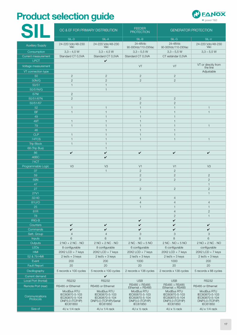
Product selection guide
SIL OC & EF FOR PRIMARY DISTRIBUTIONFEEDER
PROTECTIONGENERATOR PROTECTION
SIL-D SIL-A SIL-B SIL-G SIL-V
Auxiliary Supply24-220 Vdc/48-230
Vac24-220 Vdc/48-230
Vac24–48Vdc
90-300Vdc/110-230Vac
24–48Vdc
90-300Vdc/110-230Vac24-220 Vdc/48-230
Vac
Consumption 3,3 – 4,5 W 3,3 – 4,5 W 3,3 – 5,5 W 3,3 – 5,5 W 3,3 – 5,5 W
Current measurement Standard CT 0,5VA Standard CT 0,5VA Standard CT 0,5VA CT estándar 0,5VA
LPCT
Voltage measurement VT VTVT or directly from
the line
VT connection type Adjustable
50 2 2 2 2
50N/G 2 2 2 2
50/51 1 1
50/51N/G 1
67NI 2
50/51/67N 2 2 2
50/51/67 2 2
52 1 1 1 1 1
BF 1 1 1 1 1
49 1 1 1
49T 1 1 1 1
79 1 1 1 1 1
46 1 1 1
CLP 1 1 1 1
74TCS 1 1 1 1 1
Trip Block 1 1
68 (Trip Bus) 1
86
46BC
74CT
Programmable Logic V3 V3 V1 V1 V3
37 1 2 2
59 2 2 2
59N 2 2 2
47 1
27 2 2 2
27V1 1
32/40 4 4
81U/O 4 4 4
25 1 1 1
81R 4 2
78 2 1
IRIG-B
Counters
Commands
Sett. Group 4 4 3 3 3
Inputs 6 6 8 8 6
Outputs 2 NO + 2 NC - NO 2 NO + 2 NC - NO 2 NC - NO + 5 NO 2 NC - NO + 5 NO 2 NO + 2 NC - NO
LEDs 8 configurable 8 configurable 6 configurable 6 configurable configurable
HMI 20X2 LCD + 7 keys 20X2 LCD + 7 keys 20X2 LCD + 7 keys 20X2 LCD + 7 keys 20X2 LCD + 7 keys
52 & 79 HMI 2 led’s + 3 keys 2 led’s + 3 keys 2 led’s + 3 keys 2 led’s + 3 keys 2 led’s + 3 keys
Event 200 200 1000 1000 200
Fault Report 20 20 20 20 20
Oscillography 5 records x 100 cycles 5 records x 100 cycles 2 records x 138 cycles 2 records x 138 cycles 5 records x 88 cycles
Current demand
Local Port (frontal) RS232 RS232 USB USB RS232
Remote Port (rear) RS485 or Ethernet RS485 or EthernetRS485 + RS485
Ethernet + RS485RS485 + RS485
Ethernet + RS485RS485 or Ethernet
Communications Protocols
ModBus RTUIEC60870-5-103IEC60870-5-104DNP3.0 (TCP/IP)
IEC61850
ModBus RTUIEC60870-5-103IEC60870-5-104
DNP3.0 (TCP/IP)/SerialIEC61850
ModBus RTUIEC60870-5-103IEC60870-5-104DNP3.0 (TCP/IP)
IEC61850
ModBus RTUIEC60870-5-103IEC60870-5-104DNP3.0 (TCP/IP)
IEC61850
ModBus RTUIEC60870-5-103IEC60870-5-104DNP3.0 (TCP/IP)
IEC61850
Size of 4U x 1/4 rack 4U x 1/4 rack 4U x ½ rack 4U x ½ rack 4U x 1/4 rack
17
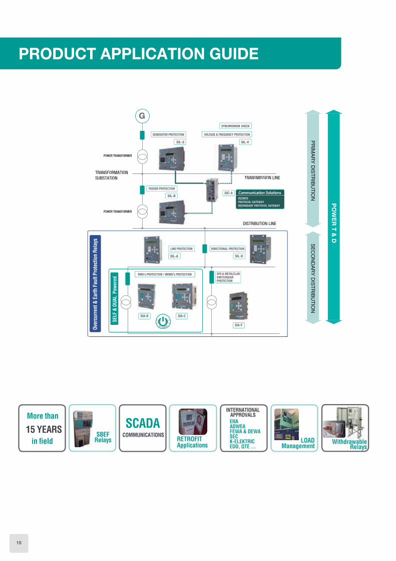
PRODUCT APPLICATION GUIDE
SE
CO
ND
AR
Y D
ISTR
IBU
TION
PO
WE
R T
& D
PR
IMA
RY
DIS
TRIB
UTIO
N
FEEDER PROTECTION
LINE PROTECTION
RMU’s PROTECTION / MRMU’s PROTECTION SF6 & METALCLADSWITCHGEARPROTECTION
TRANSFORMATOR
TRANSFORMATOR
TRANSFORMATIONSUBSTATION TRANSMISSION LINE
DISTRIBUTION LINE
SIL-B
SIL-A
GENERATOR PROTECTION
SIL-G
G
SIA-A SIA-B SIA-C
VOLTAGE & FREQUENCY PROTECTION
SIL-V
SYNCHRONISM CHECK
SIA-D SIA-E
DIRECTIONAL PROTECTION
SIL-D
SIC-A
REDBOX
PROTOCOL GATEWAY
REDUNDANT PROTOCOL GATEWAY
Communication SolutionsSIC-A
SIL-V
SYNCHRONISM CHECK
GENERATOR PROTECTION VOLTAGE & FREQUENCY PROTECTION
SIL-G
FEEDER PROTECTION
SIL-B
LINE PROTECTION DIRECTIONAL PROTECTION
SIL-A SIL-D
RMU’s PROTECTION / MRMU’s PROTECTION SF6 & METALCLADSWITCHGEARPROTECTION
SIA-A SIA-B SIA-C
SIA-D SIA-E
SIA-F SIA-D
POWER TRANSFORMER
POWER TRANSFORMER
SIA-F
SIA-B SIA-C
SELF POWERED
18

SIA-BOvercurrent and Earth Fault Protection Relay for Secondary Distribution
Dual & Self Powered
• The SIA-B is a Dual & Self powered overcurrent protection relay using the operating current through three specific current transformers fitted on the lines. These transformers are also used to obtain current measurements. Optionally, SIAB relay can be used with auxiliary power supply (24 Vdc, 110 Vac or 230 Vac). The equipment can be occasionally supplied by an external battery portable kit (KITCOM).
• Internal commissioning battery as optional.
• 50, 50/51, 50N, 50/51N protection functions.
• Trip block for switch disconnector + 49T + 49 as optional.
• Its compact size makes SIA-B really easy to install and its light weight helps the customer to save costs in transport.
• Low power consumption (0.5 W, 24 Vdc).
• Non-volatile RAM memory in order to store up to 100 events and 4 fault reports, without power supply thanks to its internal RTC (Real Time Clock).
• USB connection on the front (Modbus RTU communication protocol).
• There are bistable magnetic indicators which indicate the trip cause, maintaining their position even though the relay loses the supply (flags).
• In self powered modes, SIA-B starts-up from 0.4 Is of primary three phase current using specific CTs.
Main characteristics
Special CTsType Code *In Range Class
CT08-5 41450 3-33 A 5P80CT16-10 41452 6-65 A 10P80CT32-5 41453 12-130 A 5P80CT64-5 41454 25-260 A 5P80CT128-5 41455 51-520 A 5P80CT256-5 41456 102-1040 A 5P80
EPOXY RESIN* In is the value of the primary nominal current of
the transformer.
* In is the value of the primary nominal current of the transformer.
Special CTsType Code *In Range Class
CT08-5 Taped 41465 3-33 A 5P80CT16-5 Taped 41451 6-65 A 5P80
TAPED CTS
Specific CTs for SIA-B Relays
20

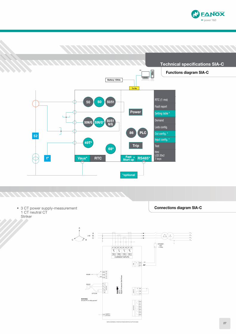
• 3 CT power supply-measurement Striker
Functions diagram SIA-B
Technical specifications SIA-B
Connections diagram SIA-B
Technical specifications SIA-B
Battery
49T* 49*
50/51
Flag* RTC FRAM Ext. Trip*Vaux*
Trip*Block
50N 50/51N
USB
21

Technical parameters SIA-Band Specific CTs
Application Indoor UseClass of insulation Class EFrequency 50-60 HzRatio …/ 0,075 APrimary Conductor Cable max. ø 50 mm
Sec. wire diameter Terminal for 6 mm2 solid/ 4 mm2 strand (Wire NOT included)
Test winding 0,288 A NominalBurden 0,1 VAProtection 5P80/10P80Material PU & PA6.6
Application Indoor UseClass of insulation Class AFrequency 50-60 HzRatio …/ 0,075 APrimary Conductor Cable max. ø 75 mm
Sec. wire diameter /length 2,5 mm2 / 500 mm (Wire included)
Test winding 0,288 A NominalBurden 0,05 VAProtection 5P80
Technical parameters EPOXY RESINED CTS Technical parameters TAPED CTS
Function 50
Permission: yes/no
Operating range: 0.20 to 20 x Is (step 0.01)
Operating time: 0.02 to 300 s (step 0.01 s)
Activation level 100%
Deactivation level 90%
Instantaneous deactivation
Timing accuracy: ± 40 ms or ± 0.5% (greater of both)
Function 50N
Permission: yes/no
Operating range: 0.20 to 20 x Is (step 0.01)
Operating time: 0.05 to 300 s (step 0.01s)
Activation level 100%
Deactivation level 90%
Instantaneous deactivation
Timing accuracy: ± 40 ms or ± 0.5% (greater of both)
Function 50/51
Permission: yes/no
Operating range: 0.20 to 7 x Is (step 0.01)
Curves: IEC 60255-151 and ANSI-IEEE
Operating time: IEC Inverse curve, IEC very inverse curve, IEC extremely inverse curve IEC long time inverse, ANSI Inverse curve, ANSI very inverse curve, ANSI extremely inverse curve.
Defined time: 0.02 to 300 s (step 0.01 s)
Dial: 0.05 to 1.25 (step 0.01)
Curve, activation level 110%
Curve, deactivation level 100%
Defined time, activation level 100%
Defined time, deactivation level 90%
Instantaneous deactivation
Timing accuracy: ± 40 ms or ± 5% (greater of both, considering the operating time is influenced by the used CT)
Function 50/51N
Permission: yes/no
Operating range: 0.20 to 7 x Is (step 0.01)
Curves: IEC 60255-151 and ANSI-IEEE
Operating time: IEC Inverse curve, IEC very inverse curve, IEC extremely inverse curve IEC long time inverse, ANSI Inverse curve, ANSI very inverse curve, ANSI extremely inverse curve.
Defined time: 0.02 to 300 s (step 0.01 s)
Dial: 0.05 to 1.25 (step 0.01)
Curve, activation level 110%
Curve, deactivation level 100%
Defined time, activation level 100%
Defined time, deactivation level 90%
Instantaneous deactivation
External trip. Charging time 7 seconds
Function 49T (*) Charging time 10 s (optional)
Function 49 (*)
Function permission: yes/no
Tap: 0.10 a 2.40 Is (step 0.01)
heating: 3 a 600 minutes (step 1 min)
cooling: 1 a 6 x heating (step 1)
Alarm level: 20 a 99% (step 1 %)
Trip level: 100%
Trip reset: 95% of alarm level
Timing accuracy: ± 5% regarding theoretical value
Trip Block (*)Blocking: Yes/no
Blocking limit: 1.5 to 20 x In (step 0.01)
Trip output24 Vdc; 135 mJ (activation of the striker or low powered coil)
Frequency 50/60Hz
Current measureTrue RMS
Sampling: 16 samples/cycle
Fault reports Four fault reports
Communication USB port: Modbus RTU
Auxiliary supply230 Vac, ±20 %
110 Vac, ±20 %
24 Vdc, ±20 %
Battery supplyWith USB KITCOM adapter
Commissionig battery(*)
Self-power from
current
Three phase self-power level: I > 0,4 x Is min
Environment
Operating temperature: -40 to 70ºC
Storage temperature: -40 to 80 ºC
Humidity: 95%
Transformers Power supply and measurement specific CTs
Mechanical
features
Metallic box
Panel Mounting
¼ Rack-4U
IP-54 panel mounted
(*) Optional depending on the model
22

120.65 56.2107
ø6ø6
ø6 ø6
991
67
.8
10
1.6
10
1.6
16
5
31
.7
31
.7
16
1.8
CUTOUT
120.65
96.71
167.8
161.8
Dimensions Resined epoxi CT
Dimensions CT16-05 Taped
Dimensions CT08-05 Taped
Dimensions CT16-05 Taped
80 mm
35 mm
ID 75 mm
OD 115 mm
Cable 2,5 mm2 / 2.500 mm
WHITE
BLUE
BLACK
RED
S1
S2
DC
150 mm ID 75 mm
OD 115 mm
Cable 2,5 mm2 / 500 mm
WHITE
BLUE
BLACK
RED
S1
S2
DC
Dimensions CT08-05 Taped
Dimensions and cutout SIA-B
100
B8
122
62
6
100
130
115
23.2
100
A
Ø 6.520
60
24.823.4
23

SIA-BOvercurrent & Earth Fault Protection
Relay - Dual & Self Powered
PROTECTION FUNCTIONS
50 + 50/51 + 50N + 50/ 51N
0
PHASE MEASUREMENT
Defined by General Settings
0NEUTRAL MEASUREMENT
Internal measurement
0NET FREQUENCY
Defined by General Settings
0
1
2
3
A
B
C
D
POWER SUPPLY
Self powered
Self powered + 230 Vac (Dual)
Self powered + 110 Vac (Dual)
Self powered + 24 Vdc (Dual)
Self powered + Commissioning battery
Self powered + 230 Vac (Dual) + Commissioning battery
Self powered + 110 Vac (Dual) +Commissioning battery
Self powered + 24 Vdc (Dual) + Commissioning battery
0
1
B
ADDITIONAL FUNCTIONS
-+ 49+ Trip Block for switch disconnector
0
COMMUNICATIONS
USB (Modbus RTU)
0
1
2
INPUTS-OUTPUTS
Trip (striker)Trip (striker) + External trip input (49T) + 1 magnetic indicatorTrip (striker) + External trip input (49T) + 1 magnetic indicator + 2 outputs
0
1
MECHANICAL ASSEMBLY
Vertical AssemblyHorizontal Assembly
A
B
C
D
LANGUAGE
English, Spanish and GermanEnglish, Spanish and TurkishEnglish , Spanish and FrenchEnglish , Spanish and Russian
A
ADAPTATION
-
Example of ordering code:
SIA B 0 0 0 0 1 0 1 0 B A SIAB 0 0 0 0 1 0 1 0 B A
Selection & Ordering data
SIA-B
24

Application and installation options for our SIA-B Relay
• Specific Current Transformers lay offers a really reduced dimensions, making this relay suitable for RMUs and compact switchgears in those installations where the space is critical.
The current adaptation is carried out by the specific external CTs, that apart from adapting the current to valid values for the relay electronic, allow to work with wider primary ranges than the standard CTs. E.g. With only one model of CT, CT-16, it is possible to protect switchgears from 300 kVAs to 1500 kVAS.
A suitable application is the transformation switchgears in wind turbines. In this case, the space is very reduced and protection for different powers with a unique CT is required.
Apart from a complete protection, SIA-B is provided with events and fault reports for an exhaustive analysis of the fault situation, magnetic indicators (flags) to signal the trip maintaining their position even when the power supply is lost and front USB to power the relay and to communicate through a USB cable connected directly to the PC.
Understood these advantages, SIA-B relay becomes an optimum solution for the described applications and therefore, FANOX has developed a complete family of specific CTs for different primary ranges to adapt this solution to different installations.
• Mounting solutions
Installation on the bushings
Many switchgears manufacturers use standard cable connectors (bushings) with some pre-defined dimensions. This fact allows Fanox to design some taped CTs that are mounted on the bushings.
Installation on the cables
Other switchgears are provided with a gap (drawer) at the bottom part of the switchgear to access to the current cables. In this way, the CTs are mounted directly on the mentioned current cables. To cover this application, Fanox has designed some epoxy resin CTs with special anchors to be fixed at the bottom of the switchgear.
Test Winding
SIA-B relay works with current transformers with secondary different to 1 A or 5 A. For this reason, it is not possible to inject secondary current directly through CT S1-S2 terminals.
In this case, the current transformer, is provided with a second winding (C-D terminals) to inject secondary current. This secondary current will induce a primary current in the relay what facilitates the functional tests performance.
CURRENT
TRANSFORMER
Injected
current
Induced primary
current
CT-08 1 A 25 A
CT-16 1 A 50 A
CT-32 1 A 100 A
CT-64 1 A 200 A
CT-128 1 A 400 A
CT-256 1 A 800 A
For example, with CT16, if 1A is injected through the test winding
terminals, a primary current of 50 A will be read in the relay.
Depending on the used CT, the induced primary current when 1
A is injected is as follows:
25

SIA-C
• The SIA-C is a overcurrent protection relay with self powered and dual powered (self + auxiliary) models.
• The relay is self powered using the operating current through three /5 (5VA) or /1 (2.5VA) standard current transformers fitted on the lines. These transformers are also used to obtain current measurements. Optionally, SIAC relay can be used with auxiliary power supply (24 Vdc, 230 Vac, 48 Vdc or 85-265 Vdc/ac). The equipment can be occasionally supplied by an external battery portable kit (KITCOM).
• Internal Commissioning battery as optional.
• 50, 50/51, 50N/G, 50/51 N/G, 86, PLC protection functions.
• 49T,CLP and 68 as optional protection functions.
• Specific test menu is provided.
• High electromagnetic compatibility.
• The installation and subsequent maintenance of batteries is eliminated. The operating costs of the centre are reduced.
• In self powered modes, the start-up of the relay from 0.1 times of the nominal current in three phases ensures capacity to trip at low energy levels.
• The line opening mechanism is activated either by means of a striker PRT, operated by the energy supplied by the relay itself, or by a coil using the TCM trip adapter in case it is necessary.
• There are bistable magnetic indicators which indicate the trip cause, maintaining their position even though the relay loses the supply (flags).
• Different sizes of SIA-C relay available by model list to fulfil all the needs of our customers and make the installation easier.
• SIA-C is fitted with the demand of current with the following characteristics:
Number of records: 168Recording mode circularSampling rate (interval): configurable through communications: 1 – 60 min
• Non-volatile RAM memory in order to store up to 1.024 events and 20 fault report, without power supply thanks to its internal RTC (Real time clock).
Main characteristics
Overcurrent and Earth Fault Protection Relay for Secondary Distribution
Dual & Self Powered
Suitable CTs for SIA-C Relays
Primary
.../ 1AModel Code Protection Self power Measurement
30 CT-30 – MTP30/1RC80 13510 0,12 VA 2,5 VA 3%
150 CT-150 – MTP150/1RC80 13515 2,9 VA 2%
25 & 100 CT-MULTITAP100-25 41740 2,5 VA -
For other transformation ratios please consult.
CT-30 CT-MULTITAP 100-25CT-150
26
Functions diagram SIA-C
Connections diagram SIA-C• 3 CT power supply-measurement 1 CT neutral CT Striker
Technical specifications SIA-C
Battery 12Vdc
49T*
68*
50/51N/G50N/G
50/51
Events
PLC86
Fast Start up
RTC (1 ms)
Setting table *
Demand
Fault report
Leds config.
Input config. *
Out config. *
Test
Hmi
7 keysLCD 20x2
50
50N/G*
27

Connections diagram SIA-C
• 3 CT power supply-measurement Rigid neutral
Potential free + TCM
• 3 CT power supply-measurement Rigid neutral Striker Withdrawable model
28

Connections diagram SIA-C
Technical specifications SIA-C
• 4 CT measurement + 3 CT self-power Potential free +TCM
CTs Technical parameters and dimensions
CT-30 / CT-150
Maximum Voltage Um / Isolation voltage 0,72 kV / 3kV
Frequency 50/60 Hz
Isolation class Clase B (130°C)
Short-circuit termal intensity Ith 25 kA – 1s
Short-circuit dynamic intensity Idyn 50 kA
Plastic enclosure and internal resin self-extinguishing, halogen-free UL94-VO
Aprox. weight 3 Kgs
Connection cable (Hose) Silicone covered yellow hose with thermo-shrinking reinforcement, halogen-free, 2x2,5mm2, length 2m, outer diameter 7 mm.
CT-30 CT-150
SECONDARY FOR PROTECTION POWER SUPPLY PROTECTION/POWER SUPPLY
Connection cable (Hose) Green(S1-S2) Yellow(S1-S2) Green (S1-S2)
Transformation ratio 30/1 30/1 150/1
Protection class 5P Alimentación 5P
Accuracy limit factor 10 - 10
Rated burden 0,12 VA 2,5 VA 2,9 VA
CT-MULTITAP100-25
Maximum Voltage Um / Isolation voltage 0,72 kV / 3kV
Frequency 50/60 Hz
Rated burden 2,5 VA
Protection class 5P
Accuracy limit factor 10
Secondary connection cable (Hose) 2,5 mm2, length 2,5m S1-Red, S2-Black, S3-White
CT-30 and CT-150
CT-multitap 100-25
29

Dimensions and cutout SIA-C
Vertical assembly
Mechanical assembly: D
290.3
177.
8
Vertical assemblyCompact size
Mechanical assembly: E, G
Horizontal assembly
Mechanical assembly: B, C
WithwadrableVertical assemblyCompact size
Mechanical assembly: F
8586
100.75
161.8
279.5
101.
6
101.
6
31.7
31.7
165
269.5
152
9.5
30

Technical specifications SIA-C
Technical parameters SIA-C
Function 50_1
Function 50_2 (*)
Permission: yes/no
Operating range: 0.10 to 30 x In (step 0.01 x In)
Operating time: 0.02 to 300 s (step 0.01 s)
Activation level 100%
Deactivation level 95%
Instantaneous deactivation
Timing accuracy:± 30 ms or ± 0.5% (greater of both)
Function 50N/G_1
Function 50N/G_2 (*)
Permission: yes/no
Operating range: 0.10 to 30 x In (step 0.01 x In)
Operating time: 0.02 to 300 s (step 0.01 s)
Activation level 100%
Deactivation level 95%
Instantaneous deactivation
Timing accuracy: ± 20 ms or ± 0.5% (whichever is greater)
Function 50/51
Permission: yes/no
Operating range: 0.10 to 7 x In (step 0.01 x In)
Curves: IEC 60255-151 and ANSI-IEEE
Operating time: IEC Inverse curve, IEC very inverse curve,IEC extremely inverse curve IEC long time inverse, ANSI Inverse curve, ANSI very inverse curve, ANSI extremely inverse curve.
Defined time: 0.02 to 300 s (step 0.01 s)
Dial: 0.02 to 1.25 (step 0.01)
Curve, activation level 110%
Curve, deactivation level 100%
Defined time, activation level 100%
Defined time, deactivation level 95%
Instantaneous deactivation
Timing accuracy: ± 5% or ±30 ms (whichever is greater) when the protection works with inverse time and ± 20 ms or ± 0.5% (whichever is greater) when it works with definite time
Function 50/51N/G
Permission: yes/no
Operating range: 0.10 to 7 x In (step 0.01 x In)
Curves: IEC 60255-151 and ANSI-IEEE
Operating time: IEC Inverse curve, IEC very inverse curve,IEC extremely inverse curve IEC long time inverse, ANSI Inverse curve, ANSI very inverse curve, ANSI extremely inverse curve.
Defined time: 0.02 to 300 s (step 0.01 s)
Dial: 0.02 to 1.25 (step 0.01)
Curve, activation level 110%
Curve, deactivation level 100%
Defined time, activation level 100%
Defined time, deactivation level 95%
Instantaneous deactivation
Timing accuracy: ± 5% or ±30 ms (whichever is greater) when the protection works with inverse time and ± 20 ms or ± 0.5% (whichever is greater)when it works with definite time
Function CLP (*)
Permission: yes/no
Settings group: 1 to 4 (step 1)
No load Time: 0.02 to 300 s (step 0.01 s)
Cold load Time: 0.02 to 300 s (step 0.01 s)
CLP activation threshold: 8% In
CLP reset threshold: 10% In
Function 49T (*) Charging time 10 s
Function 68 (*)Available through configurable inputs and outputs thanks to programmable logic
Programmable logic control (PLC)
OR4, OR4_LATCH, OR4_PULSES, OR4_TIMERUP, OR4_PULSE, NOR4, NOR4_LATCH, NOR4_TIMERUP, NOR4_PULSE, AND4, AND4_PULSES, AND4_TIMERUP, AND4_PULSE, NAND4, NAND4_TIMERUP, NAND4_PULSE
Function 86Allows to latch (lock out) the contact configured like trip due to programmable logic (PLC).
Settings tables (*)
Adaptation A: 3 settings tables Activated by inputs or by general settings.Adaptation B: 4 settings tables
Activated by inputs or by general settings
Fault reports 20 fault reports, 16 events in each
Demand of current
Demand of current with the following characteristics• Number of records: 168• Recording mode circular• Sampling rate (interval): configurable through
communications: 1 – 60 min• Record format:
Date/TimeIMAX (in interval)IMAX (actual)IA - IC - IN
Trip output
For Striker: 24 Vdc-135 mJFor coil (optionally with TCM adapter): 250 Vac – 8A 30 Vdc – 8A Resistive load (cos φ = 1)
Signalling outputs (*)
Up to 3 outputs (output 2, output 3 and output 4):220 Vdc – 1 A (30 W max)250 Vac – 1 A (62,5 VA max)
Signalling inputs (*) 2 inputs: 5-24 Vdc – 0,25 VA
Frequency 50/60Hz
Current measure
RMS
Sampling: 16 samples/cycle
Accuracy of 2% on a band of ±20% over the nominal current and 4% over the rest of the range.
CommunicationRS232 port: Modbus RTU
RS485 port: Modbus RTU (*)
Auxiliary supply (*) 230 Vac, ±20 % - 24 Vdc ±10 % 48 Vdc ±10 %
- 85-265 Vdc/Vac ±20 %
Battery supplyExternally, with adapter (Kitcom) port DB9
Internal commissioning battery (*)
Self-power from current
One phase self-power level:
I > 0,2 x In
Environment
Operating temperature: -40 to 70ºC
Storage temperature: -40 to 80 ºC
Humidity: 95%
Transformers Power supply and measurement CT /5 or /1
Mechanical features
Metallic box
Panel Mounting
1/3 Rack – 4 U (mechanics type D, E, F and G)
3/5 Rack – 4 U (mechanics type B and C)
IP-54
(*) Optional depending on model31

SIA-COvercurrent & Earth Fault Protection
Relay - Dual & Self Powered
PROTECTION FUNCTIONS
50 + 50/51 + 50N/G + 50/51N/G + 86 + PLC
15
PHASE MEASUREMENT
In = 1 A; (0,10 – 30,00 A)In = 5 A; (0,50 – 150,00 A)
15AB
NEUTRAL MEASUREMENT
In = 1 A; (0,10 – 30,00 A)In = 5 A; (0,50 – 150,00 A)In = 0,1 A; (0,01 – 3,00 A)In = 0,2 A; (0,02 – 6,00 A)
56
NET FREQUENCY
50 Hz60 Hz
01345ABDEF
POWER SUPPLY
Self poweredSelf powered + 230 Vac (Dual)Self powered + 24 Vdc (Dual)Self powered + 48 Vdc (Dual)Self powered + 85-265 Vac-dc (Dual)Self powered + Commissioning batterySelf powered + 230 Vac (Dual) + Commissioning batterySelf powered + 24 Vdc (Dual) + Commissioning batterySelf powered + 48 Vdc (Dual) + Commissioning batterySelf powered + 85-265 Vac-dc (Dual) + Commissioning battery
01234
ADDITIONAL FUNCTIONS
StrikerStriker and with external trip (49T)CoilCoil and with external trip (49T)Striker and 230 Vac adapted external trip
01
COMMUNICATIONS
Local ModBus port (RS 232)+ Remote ModBus port (RS485)
0123
INPUTS-OUTPUTS
TripTrip + 2 outputsTrip + 2 outputs + 2 inputsTrip + 3 outputs
12
FAST START-UP
Non-volatile RAM memoryNon-volatile RAM memory + Fast start-up
ABCD
LANGUAGE
English, Spanish and GermanEnglish, Spanish and TurkishEnglish, Spanish and FrenchEnglish , Spanish and Russian
BCDEF
G
MECHANICS
Horizontal assembly with 1 magnetic FlagHorizontal assembly with 3 magnetic FlagVertical assembly with 1 magnetic FlagVertical, Compact Size with 3 magnetic FlagVertical, Compact Size, 2 Flags, Backlight LCD, withdrawableVertical, Compact Size, 1 Flag, Backlight LCD
-AB
ADAPTATION
50 + 50/51 + 50N/G + 50/51N/G + 86 +PLC+ 50P_2 + 50N/G_2 + 3 Setting groups+ CLP + 4 Setting groups
Example of ordering code:
SIA C 1 5 5 0 0 0 2 2 A F A SIAC 1 5 5 0 0 0 2 2 AFA
Selection & Ordering data
SIA-C
32

Some success applications for our SIA-C Relay
• Ring Main Unit used for Metering (MRMU) for MV applications (13.8kV, 36kV and 38kV) in a busbar rating up to 630A.
In this application a protection relay is included to protect the line by tripping the circuit breaker of the position, apart from voltage and current meter or energy analyzer.
Many MRMU manufacturers provide a 24 Vdc auxiliary power supply so the SIA-C Self and Dual Powered Relay at 24Vdc is the appropriate solution.
• Standby Earth Fault Relay model designed as a backup protection to clear a remote earth fault on the downstream network. This relay performs 50P + 50/51P + 50N/G + 50/51N/G functions and shows 3 magnetic flags in its front indicating the tripping reason.
• Withdrawable Self powered model with a very compact size makes the installation and maintenance much easier.
• Perfect solution for RETROFIT applications. Combined with TCM adapter this application is performed in these RMUs where the existing protection relay is replaced with a new generation digital relay like FANOX SIA-C.
The auxiliary power of the RMU energizes the TCM that activates the coil when the relay detects a fault condition.
RMU manufacturer do not require changing the existing circuit breaker and coil, SIA-C along with TCM adapter work as one supplying the energy needed to trip the coil. TCM provides the most common variety of auxiliary voltages that coils require: 48Vdc, 110Vdc or 220Vdc.
33

SIA-FOvercurrent and Earth Fault Protection Relay for Secondary Distribution
Main specifications
• The SIA-F is an overcurrent protection relay with a switched auxiliary power supply (24-220 Vdc / 480-230 Vac). The current is measured by using /5 or /1 current transformers. The equipment can be occasionally supplied by an external battery portable kit (KITCOM).
• 50, 50/51, 50N/G, 50/51 N/G, CLP, 86 protection functions.• Trip block for switch disconnector, 49, 49T, 52, 50BF, as optionals.• High electromagnetic compatibility.• With circuit breaker control and monitoring (circuit breaker status, number
of openings, accumulated amperes, etc.).• Compact size with reduced depth makes it easier to install and saves costs.• USB connection on the front (Modbus RTU communication protocol).• A specific test menu is provided.• Possibility of external battery power supply (KITCOM).• There are three configurable LED indicators on the front of the SIA-F
equipment. By default, they indicate indicate if the equipment is On (LED ON), if an alarm has happened (LED ALARM) or if a trip has happened (LED TRIP).
• Programmable logic (PLC)• 1 Oscillographic record, non-volatile RAM memory in order to store up to
200 events and 4 fault reports, without power supply thanks to its internal RTC (Real Time Clock)
Technical specifications
Functions diagram SIA-F
Additional information to fault reports
Battery
USB
* By model list
110-230 Vac / 90-300 Vdc
24-48 Vdc
V*Aux
O*
I*
RTC FRAM RS485*
Trip*Block49T*
50BF*52*
68*
PLC
86
50N/G
49*CLP
50/51N/G
50/51
34

Connections diagram SIA-F• 3 CT measurement 1 CT sensitive neutral
A
CBLINE
A7
A6TR
IP
+ -
LOC
AL
PO
RT
Ground PC to relay ground
* A
UX
.P
OW
ER
SIA
-FO
C&
EF
Pro
tect
ion
L1
L2
L3
N
A
C B
A13
A14
COIL
KITCOM
AC
/DC
-+
min
i US
B
NCBA
Measure Measure Measure Measure
CURRENT INPUTS
INP
UT
S
A10
A12
A8
A11
A9
OU
TP
UT
S
A3
A4
A5
NO
NC
common
RS485 RS
485A1
A2
+
-
35
Technical parameters SIA-F
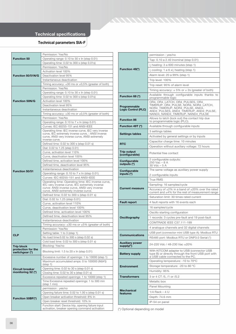
Technical specifications
Function 50
Permission: Yes/No
Operating range: 0.10 to 30 x In (step 0.01)
Operating time: 0.02 to 300 s (step 0.01s)
Function 50/51N/G
Permission: Yes/No
Activation level 100%
Deactivation level 95%
Instantaneous deactivation
Timing accuracy: ±30 ms or ±0,5% (greater of both)
Function 50N/G
Permission: Yes/No
Operating range: 0.10 to 30 x In (step 0.01)
Operating time: 0.02 to 300 s (step 0.01s)
Activation level 100%
Deactivation level 95%
Instantaneous deactivation
Timing accuracy: ±30 ms or ±0,5% (greater of both)
Function 50/51
Permission: Yes/No
Operating range: 0.10 to 7 x In (step 0.01)
Curves: IEC 60255-151 and ANSI-IEEE
Operating time: IEC inverse curve, IEC very inverse curve, IEC extremely inverse curve, : ANSI inverse curve, ANSI very inverse curve, ANSI extremely inverse curve.
Defined time: 0.02 to 300 s (step 0.01 s)
Dial: 0.02 to 1.25 (step 0.01)
Curve, activation level 110%
Curve, deactivation level 100%
Defined time, activation level 100%
Defined time, deactivation level 95%
Instantaneous deactivation
Operating range: 0.10 to 7 x In (step 0.01)
Curves: IEC 60255-151 and ANSI-IEEE
Operating time: Operating time: IEC inverse curve, IEC very inverse curve, IEC extremely inverse curve: ANSI inverse curve, ANSI very inverse curve, ANSI extremely inverse curve.
Defined time: 0.02 to 300 s (step 0.01 s)
Dial: 0.02 to 1.25 (step 0.01)
Curve, activation level 110%
Curve, deactivation level 100%
Defined time, activation level 100%
Defined time, deactivation level 95%
Instantaneous deactivation
Timing accuracy: ±30 ms or ±5% (greater of both)
CLP
Permission: Yes/No
Setting table: 1 to 3 (step 1)
No load time:0.02 to 300 s (step 0.02 s)
Cold load time: 0.02 to 300 s (step 0.01 s)
Trip block protection for the switchgear (*)
Blocking: Yes/no
Blocking limit: 1.5 to 20 x In (step 0.01)
Circuit breaker monitoring 52 (*)
Excessive number of openings: 1 to 10000 (step 1)
Maximum accumulated amps: 0 to 100000 (M(A²)) (step 1)
Opening time: 0.02 to 30 s (step 0.01 s)
Closing time: 0.02 to 30 s (step 0.01 s)
Excessive repeated openings: 1 to 10000 (step 1)
Time Excessive repeated openings: 1 to 300 min (step 1 min)
Function 50BF(*)
permission : yes/no
Opening failure time: 0.02 to 1.00 s (step 0.01 s)
Open breaker activation threshold: 8% In
Open breaker reset threshold: 10% In
Function start: Device trip, opening failure input activation, breaker opening command activation
Function 49(*)
permission : yes/no
Tap: 0.10 a 2.40 Inominal (step 0.01)
heating: 3 a 600 minutes (step 1)
cooling: 1 a 6 x heating (step 1)
Alarm level: 20 a 99% (step 1)
Trip level: 100%
Trip reset: 95% of alarm level
Timing accuracy: ± 5% or ± 2s (greater of both)
Function 68 (*)Available through configurable inputs thanks to programmable logic
Programmable Logic Control (PLC)
OR4, OR4_LATCH, OR4_PULSES, OR4_TIMERUP, OR4_PULSE, NOR4, NOR4_LATCH, NOR4_TIMERUP, NOR4_PULSE, AND4, AND4_PULSES, AND4_TIMERUP, AND4_PULSE, NAND4, NAND4_TIMERUP, NAND4_PULSE
Function 86Allows to latch (lock out) the contact trip dueto programmable logic (PLC).
Function 49T (*) Available through configurable inputs
Settings tables3 settings tables
Activated by general settings or by inputs
RTCCapacitor charge time: 10 minutes
Operation without auxiliary voltage: 72 hours
Trip output (configurable)
Potential free contact
Configurable outputs (*)
2 configurable outputs: 250 Vac – 8 A 30 Vdc – 5 A
Configurable inputs (*)
The same voltage as auxiliary power supply
2 configurable inputs
Current measure
True RMS
Sampling: 16 samples/cycle
Accuracy of ±2% in a band of ±20% over the rated current and ±4% for the rest of measurement range
Saturation limit: 30 times rated current
Fault report 4 fault reports with 16 events each
Oscillography
16 samples/cycle
Oscillo starting configuration
1 records: 3 cycles pre-fault and 19 post-fault
COMTRADE IEEE C37.111-199
4 analogue channels and 32 digital channels
CommunicationsUSB port (connector mini USB type A): Modbus RTU
RS485 port: Modbus RTU or DNP3.0 Serial (*)
Auxiliary power supply(*)
24-220 Vdc / 48-230 Vac ±20%
Battery supplyWith KITCOM adapter to USB (connector USB type B) or directly through the front USB port with a USB cable connected to the PC.
Environment
Operating temperature: -10 to 70ºC
Storage temperature: -20 to 80 ºC
Humidity: 95%
Transformers 3 or 4 CT /5, /1 or /0.2
Mechanical features
Metallic box
Panel Mounting
1/4 Rack – 4 U
Depth: 74.6 mm
IP-54 on panel
(*) Optional depending on model
36

51.2
16
1.8
120.65
16
7.8
99
107
10
1.6
10
1.6
31
.7
31
.7
ø6
ø6
ø6
ø6
4
4
16
5CUTOUT
Selection & Ordering data
SIA-F
Dimensions and cutout SIA-F
SIA-FOvercurrent & Earth Fault Protection Relay PROTECTION FUNCTIONS
50 + 50/51 + 50N/G + 50/51N/G + 86 + PLC + Cold Load Pick-up
1
5
PHASE MEASUREMENT
In = 1 A; (0,10 – 30,00 A)In = 5 A; (0,50 – 150,00 A)
1
5
B
NEUTRAL MEASUREMENT
In = 1 A; (0,10 – 30,00 A)In = 5 A; (0,50 – 150,00 A)In = 0,2 A; (0,02 – 6,00 A)
0
NET FREQUENCY
Defined by General Setting
C
POWER SUPPLY
24–220 Vdc / 48-230 Vac
0
1
B
C
ADDITIONAL FUNCTIONS
-+ 49 + 52 + 50BF+ Trip block for switch disconnector+ Trip block for switch disconnector + 49 + 52 + 50BF
0
1
2
COMMUNICATIONS
USB (Modbus RTU)USB (Modbus RTU) + RS485 (Modbus RTU)USB (Modbus RTU) + RS485 (DNP3.0 Serial)
0
1
INPUTS - OUTPUTS
TripTrip + 2 inputs + 2 outputs
0
MECHANICS
4U x 1/4 rack
A
B
C
D
LANGUAGE
English, Spanish and GermanEnglish, Spanish and TurkishEnglish, Spanish and French English, Spanish and Russian
A
ADAPTATION
-
Example of ordering code:
SIA F 1 1 0 C 0 1 1 0 C A SIAF 1 1 0 C 0 1 1 0 C A
37
SIL-DOvercurrent and Directional Earth Fault Protection
• SIL-D relay is an overcurrent and directional earth fault protection relay for Primary and Secondary Distribution.
• Auxiliary power supply (24-220 Vdc / 48-230 Vac).
• Protection functions: (2) 50 + 50/51 + (2) 50N/G + (2) 50N/51N/67N(1) + 52 + 50BF + 79 + 74TCS + CLP + 86 + 49T + 59N. Optionally, directional isolated neutral overcurrent(2) : 67NI_1 and 67NI_2.
It includes switch disconnector protection function by means of trip blocking.
• Function 67NI. Directional neutral isolated overcurrent with two neutral directional units: 67NI_1 and 67NI_2.
This function is based on two supervisions: The analogue to the one that uses the 67N to check that the residual current is inside the defined area by the settings of directionality, operation angle and halfcone, and the second supervision of the modules of the residual voltage and current.
To perform the directional detection, the residual voltage is used as polarization magnitude and the residual current as an operating magnitude. The intervention sector in forward direction is defined in the following way: the operating angle is rotated anticlockwise from the negative residual voltage,-V0 which gives us the maximum torque direction. A cone is drawn, with the half-cone angle adjusted, over this maximum torque direction. In the same way, the intervention sector in reverse direction is defined in the following way: the operating angle is rotated anticlockwise from the positive residual voltage, V0 which gives us the maximum torque direction. A cone is drawn, with the half-cone angle adjusted, over this maximum torque direction.
When 67NI is not activated the functions works like 50/51G.
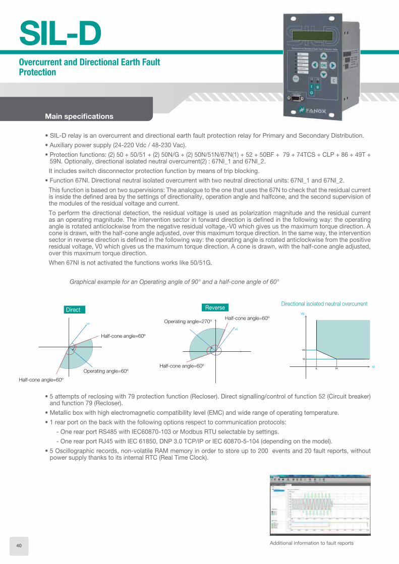
Graphical example for an Operating angle of 90° and a half-cone angle of 60°
• 5 attempts of reclosing with 79 protection function (Recloser). Direct signalling/control of function 52 (Circuit breaker) and function 79 (Recloser).
• Metallic box with high electromagnetic compatibility level (EMC) and wide range of operating temperature.
• 1 rear port on the back with the following options respect to communication protocols:
- One rear port RS485 with IEC60870-103 or Modbus RTU selectable by settings.
- One rear port RJ45 with IEC 61850, DNP 3.0 TCP/IP or IEC 60870-5-104 (depending on the model).
• 5 Oscillographic records, non-volatile RAM memory in order to store up to 200 events and 20 fault reports, without power supply thanks to its internal RTC (Real Time Clock).
Main specifications
Additional information to fault reports
Directional isolated neutral overcurrentDirect
Half-cone angle=60º
Operating angle=60º
Half-cone angle=60º
Reverse
Half-cone angle=60º
Half-cone angle=60º
Operating angle=270º
40

Technical specifications SIL-D
Connections diagram SIL-D
• 3 CT Phase Current
• 2 CT Phase Current + 1 Neutral CT
41

Technical parameters SIL-D
Technical specifications
50(2)
Function permission: Yes/No
Operating range: 0.10 to 30 xIn (step 0.01)
Time delay: 0.02 to 300 s (step 0.01 s)
Activation level 100%
Deactivation level 95%
Instantaneous deactivation
Timing accuracy: ±30 ms or ±0.5% (greater of both)
50N/G(2)
Function permission: Yes/No
Operating range: 0.10 to 30 xIn (step 0.01)
Time delay: 0.02 to 300 s (step 0.01 s)
Activation level 100%
Deactivation level 95%
Instantaneous deactivation
Timing accuracy: ±30 ms or ±0.5% (greater of both)
50/51
Function permission: Yes/No
Operating range: 0.10 to 7 xIn (step 0.01)
Curves IEC 60255-151 and ANSI
Time delay: IEC Inverse curve, IEC very inverse curve,IEC extremely inverse curve IEC long time inverse, ANSI Inverse curve, ANSI very inverse curve, ANSI extremely inverse curve.
Defined time : 0.02 to 300 s (step 0.01 s)
Dial: 0.02 to 2.20 (step 0.01)
Curve, activation level 110%
Curve, deactivation level 100%
Defined time, activation level 100%
Defined time, deactivation level 95%
Instantaneous deactivation
Timer accuracy: ±5% or ±30 ms (whichever is greater)
67N(2)
Function permission: Yes/No
Operating range: 0.10 to 7 xIn (step 0.01)
V Operating range: 2 -65V (step 1V)
Curves IEC 60255-151 and ANSI-IEEE
Time delay: IEC Inverse curve, IEC very inverse curve,IEC extremely inverse curve IEC long time inverse, ANSI Inverse curve, ANSI very inverse curve, ANSI extremely inverse curve.
Definite time: 0,02 to 300s (step
Dial: 0.02 to 2.20 (step 0.01)
Directionality: No/ Forward/ Reverse
Operation angle: 0 to 359º (step 1º)
Halfcone angle: 1 to 170º (step 1º)
Curve, activation level 110%
Curve, deactivation level 100%
Defined time, activation level 100%
Defined time, deactivation level 95%
Instantaneous deactivation
Timer accuracy: ±5% or ±30 ms (whichever is greater)
67NI(2)
Function permission: Yes/No
Operating range: 0.10 to 7.00 xIn (step 0.01)
V Operating range: 2 -65V (step 1V)
Time delay: 0.02 to 300 s (step 0.01 s)
Directionality: No/ Forward/ Reverse
Operation angle: 0 to 359º (step 1º)
Halfcone angle: 1 to 170º (step 1º)
Defined time, activation level 100%
Defined time, deactivation level 95%
Timer accuracy: ±5% or ±30 ms (whichever is greater)
59N
Function permission: Yes/No
V Operating range: 2 -65 V (step 1V)
Operating range: 0.10 to 7.00 xIn (step 0.01)
Reset time: 0.02 to 300s (step 0.01s)
Circuit breaker
monitoring
Excessive number of openings: 1 to 10000 (step 1)
Maximum accumulated amps: 0 to 100000 (M(A²)) (step 1)
Opening time: 0.02 to 30 s (step 0.01 s)
Closing time: 0.02 to 30 s (step 0.01 s)
Excessive repeated openings: 1 to 10000 (step 1)
Time Excessive repeated openings: 1 to 300 min (step 1 min)
50BF
Function permission: Yes/No
Opening fault time: 0.02 to 1.00 s (step 0.01 s)
Open circuit breaker activation threshold: 8% In
Open circuit breaker reset threshold: 10% In
Function Pickup configurable: Equipment trip, activation of the opening fault input, circuit breaker open control activation.
79
Function permission: Yes/No
Hold permission: Yes/No
Number of reclosings: 1 to 5
Reclosing time 1, 2, 3, 4, 5 : 0.02 to 300 s (step 0.01 s)
Hold time: 0.02 to 300 s (step 0.01 s)
Locking possibilities: pulse inputs, level inputs, commands.
Replacement time: 0.02 to 300 s (step 0.01 s)
Definitive opening time: 0.02 to 300 s (step 0.01 s)
74TCS
Function permission: Yes/No
Time delay: 0.02 to 300 s (step 0.01 s)
Trip continuity, in circuits A and B
Configurable inputs
CLP
Function permission: Yes/No
Settings group: 1 to 4 (step 1)
No load Time: 0.02 to 300 s (step 0.01 s)
Cold load Time: 0.02 to 300 s (step 0.01 s)
CLP activation threshold: 8% In
CLP reset threshold: 10% In
PLC
OR4, OR4_LATCH, OR4_PULSES, OR4_TIMERUP, OR4_PULSE, NOR4, NOR4_LATCH, NOR4_TIMERUP, NOR4_PULSE, AND4, AND4_PULSES, AND4_TIMERUP, AND4_PULSE, NAND4, NAND4_TIMERUP, NAND4_PULSE
86Allows to latch (lock out) the contact trip due to programmable logic (PLC: LATCH).
49TAvailable through configurable inputs thanks to the programmable logic
Trip BlockBlocking: Yes/No
Blocking limit: 1.5 to 20 x In (step 0.01)
Settings tables4 settings tables
Activated by inputs or by general settings.
42

RTCCapacitor charge time: 10 minutes
Operation with no auxiliary voltage: 72 hours
Oscillography
16 samples/cycle
Fault init configurable
5 records of 100 cycles: 3 prefault and 97 postfault cycles
COMTRADE IEEE C37.111-1991
4 analog channels y 48 digital channels
Fault reports 20 fault reports with 24 events each one
Demand of
current
Demand of current with the following characteristics:• Number of records: 168• Recording mode circular• Sampling rate (interval): configurable through
communications: 1 – 60 min Record format:
Date/TimeIMAX (in interval)IMAX (actual)IAIBICIN
Configurable
inputs
Same voltage as the auxiliary power supply6 configurable inputs
Configurable
outputs
250 Vac – 8 A30 Vdc – 5 A
4 configurable outputs• Output 1 and output 2: NC + NO• Output 2 and output 4: NO
Frequency 50/60 Hz selectable by general settings
Current
measurement
Phase current (IA, IB, IC), neutral (IN) and maximum current (Imax)
Real RMS
Sampling: 16 samples/cycle
±2% Accuracy over a band of ±20% over the nominal current and 4% over the rest of the range
The measurement of IB is calculated and it is necessary a minimum of 0.25xIn for a correct measurement.
Saturation limit: 30 times rated current
Voltage
measurement
Residual voltage (VR)
Real RMS
Sampling: 16 samples/cycle
±2% Accuracy in the range of 2 - 65V
Angle between
VR and IR
±2º Accuracy angle
Minimum current for a correct angle measurement: 0.3 x In
Minimum voltage for a correct angle measurement: 2V
Communications
LOCAL COMMUNICATION1 Local port RS232: ModBus RTU
REMOTE COMMUNICATION (*)1 remote port with the following options :
• 1 Remote port RS485: ModBus RTU or IEC 60870-5-103 (by general settings)
• 1 Remote port RJ45: IEC 61850, DNP3.0 TCP/IP or IEC 60870-104
Auxiliary power 24-110 Vdc /48-230 Vac ±20%
Environmental
conditions
Operating temperature : -10 to 70ºC
Storage temperature: -20 to 80ºC
Relative humidity: 95%
Transformers Measurement 3 or 4 CT /5 or /1
Mechanical
Characteristics
Metallic box
Panel mounted.
1/4Rack – 4 U
IP-54 on pannel
(*) Optional depending on model
Technical parameters SIL-D
43

Functions diagram SIL-D
Technical specifications
Dimensions and cut-out pattern SIL-D
CUTOUT
24 24
Events
RTC (1 ms)
Oscillography
Setting table
Demand
Fault report
Leds config.
Input config.
Out config.
Test
IEC 61850*IEC 60870-5-104*DNP3.0*
Hmi
7 keys+I/052+B79LCD 20x2
IEC 60870-5-103*
RS485
ModBus*RTU
RS485
Modem
RS232
SICom
ModBus RTU.Tx, Rx
Ethernet
* optional
67N
86
52 74TCS
49T*
(1 1)
67NI 67NI* *
67N
TRIP
BLOCK7952
50 50BF50/5150 CLP
59N
IN
BUSBAR
IA,IC
VN
tº
67N --> 50/51N67N
(1)* available trough configuration
52
50N/G 50N/G
44

Selection & Ordering Data
SIL-D
SIL-D Overcurrent & Directional Earth Fault Protection Relay
PROTECTION FUNCTIONS
(2) 50 + 50/51 + (2) 50N/G + (2) 50N/51N/67N + 52 + 50BF + 79 + 74TCS + CLP + 86 + 49T + 59N + Trip block for switch disconnector
0
S
NOMINAL PHASE MEASUREMENT
Standard In = 1A or 5A; (0.1 – 30A) / (0.5 – 150A)Sensitive In = ½ A or 5/2 A; (0.05 – 15A) / (0.25 – 75A)
0
S
NOMINAL NEUTRAL MEASUREMENT
Standard In = 1A / 5A; (0.1 – 30A) / (0.5 – 150A)Sensitive In =1/10 A or 5/10 A; (0.01 – 3A) / (0.05 – 15A)
0
NET FREQUENCY
(50Hz / 60Hz). Defined by Setting
C
POWER SUPPLY
24-220 Vcc / 48-230 Vca
0
1
ADDITIONAL FUNCTIONS
-+67NI_1 + 67NI_2
A
B
C
D
REMOTE COMMUNICATIONS
RS232 (Modbus RTU) + RS485 (Modbus RTU or IEC 60870-5-103)
RS232 (Modbus RTU) + RJ45 (IEC 61850)
RS232 (Modbus RTU) + RJ45 (DNP3.0 TCP/IP)
RS232 (Modbus RTU) + RJ45 (IEC60870-5-104)
1
INPUTS AND OUTPUTS
6 Inputs + 4 Outputs
2
MECHANICS
Compact: 4U x ½ Rack
A
B
C
E
LANGUAGES
English, Spanish and GermanEnglish, Spanish and TurkishEnglish, Spanish and FrenchEnglish, Turkish and Russian
A
ADAPTATION
-
Example of ordering code:
SIL-D 0 0 0 C 1 A 1 2 B A SILD000C1A12BA
45
SIL-AOvercurrent and Earth Fault Relay for Primary and Secondary Distribution
• The SIL-A is an overcurrent and earth fault protection relay for primary and secondary distribution with auxiliary power supply 24-220 Vdc/ 48-230 Vac). The current measurement is obtained either by standard current transformers /1 or /5, or by special Low Power Current Transformers (LPCT).
• Many protection functions: 50(2), 50N/G (2)(1), 50/51, 50/51N/G(1), 50BF, 46, 52, 79, 74TCS, COLD LOAD PICK-UP, 86, 49T and optionally 49, 74CT, 37, 46 BC, trip block for switch disconnector.
• Metallic box with high electromagnetic compatibility level (EMC) and wide range of operating temperature.
• Direct signalling/control both of the circuit breaker (52 function), both of the recloser (79 function).
• Trip bus protection function is available through configurable inputs and outputs thanks to the programmable logic.
• To allow the communication, relays have a communication port on the front of the equipment and remote communication with different options:
One rear port on the back with the following options respect to communication protocols:- RS 485 PORT: IEC60870-103 or Modbus RTU selectable by settings- RJ 45 PORT: IEC 61850, DNP 3.0 or IEC 60870-5-104 (depending on model).
• The SIL-A has configurable inputs and outputs: 6 inputs (74TCS through configurable inputs) - and 4 outputs
• SIL-A is fitted with the demand of current with the following characteristics:
Number of records: 168Recording mode circularSampling rate (interval): configurable through communications: 1 – 60 min
Main characteristics
SIL-A relays installed in Azadi Football Stadium’s electrical substation.
(1) Note:• LPCT model: neutral current is calculated so overcurrent protection functions are 50N(2) and 50/51N• Compact model: neutral current is measured so overcurrent protection functions are 50N/G(2) and 50/51 N/G
46

Additional information to fault reports
50
50BF
50/51
Events
RTC (1 ms)
Oscillography
Setting table
Demand*
Fault report
Leds config.
Input config.
Out config.
Test
ColdLoadPickup
46
49*
50
50N/G* 50N/G*
86
CLP
52 74TCS79
52
IEC 61850*IEC 61870-5-104*DNP3.0*
Hmi
7 keys+I/052+B79LCD 20x2
IEC 61870-5-103*
RS485
ModBus*RTU
RS485
Modem
RS232
SICom
ModBus RTU.Tx, Rx
Ethernet
tº
50/51N/G*
49T
(1) (1) (1)
* optional
Functions diagram SIL-A
Technical specifications SIL-A
37*
TB*
74CT 46BC* *
• 5 Oscillographic records, 20 fault reports and 200 events saved in non-volatile RAM memory with date / time even without power supply thanks to its internal RTC (Real Time Clock).
(1) Note:
• LPCT model: neutral current is calculated so overcurrent protection functions are 50N(2) and 50/51N
• Compact model: neutral current is mea-sured so overcurrent protection functions are 50N/G(2) and 50/51 N/G
47

Technical parameters SIL-A
Technical specifications
50(2)
Function permission: Yes/No
Operating range: 0.10 to 30 xIn (step 0.01)
Operating time: 0.02 to 300 s (step 0.01 s)
Activation level 100%
Deactivation level 95%
Instantaneous deactivation
Timing accuracy: ±30 ms or ±0.5% (greater of both)
50N/G(2) (1)
Function permission: Yes/No
Operating range: 0.10 to 30 xIn (step 0.01)
Operating time: 0.02 to 300 s (step 0.01 s)
Activation level 100%
Deactivation level 95%
Instantaneous deactivation
Timing accuracy: ±30 ms or ±0.5% (greater of both)
50/51
Function permission: Yes/No
Operating range: 0.10 to 7 xIn (step 0.01)
Curves IEC 60255-151 and ANSI
Operating time: IEC Inverse curve, IEC very inverse curve,IEC extremely inverse curve IEC long time inverse, ANSI Inverse curve, ANSI very inverse curve, ANSI extremely inverse curve.
Defined time : 0.02 to 300 s (step 0.01 s)
Dial: 0.02 to 2.20 (step 0.01)
Curve, activation level 110%
Curve, deactivation level 100%
Defined time, activation level 100%
Defined time, deactivation level 95%
Instantaneous deactivation
Timer accuracy: ±5% or ±30 ms (whichever is greater)
50/51N/G (1)
Function permission: Yes/No
Operating range: 0.10 to 7 xIn (step 0.01)
Curves IEC 60255-151 and ANSI
Operating time: IEC Inverse curve, IEC very inverse curve,IEC extremely inverse curve IEC long time inverse, ANSI Inverse curve, ANSI very inverse curve, ANSI extremely inverse curve.
Defined time : 0.02 to 300 s (step 0.01 s)
Dial: 0.02 to 2.20 (step 0.01)
Curve, activation level 110%
Curve, deactivation level 100%
Defined time, activation level 100%
Defined time, deactivation level 95%
Instantaneous deactivation
Timer accuracy: ±5% or ±30 ms (whichever is greater)
46
Function permission: Yes/No
Operating range: 0.10 to 7.00 xIn (step 0.01)
Curves IEC 60255-151 and ANSI
Operating time: IEC Inverse curve, IEC very inverse curve,IEC extremely inverse curve IEC long time inverse, ANSI Inverse curve, ANSI very inverse curve, ANSI extremely inverse curve.
Defined time : 0.02 to 300 s (step 0.01 s)
Dial: 0.02 to 2.20 (step 0.01)
Curve, activation level 110%
Curve, deactivation level 100%
Defined time, activation level 100%
Defined time, deactivation level 95%
Instantaneous deactivation
Timer accuracy: ±5% or ±30 ms (whichever is greater)
Circuit breaker
monitoring
Excessive number of openings: 1 to 10000 (step 1)
Maximum accumulated amps: 0 to 100000 (M(A²)) (step 1)
Opening time: 0.02 to 30 s (step 0.01 s)
Closing time: 0.02 to 30 s (step 0.01 s)
Excessive repeated openings: 1 to 10000 (step 1)
Time Excessive repeated openings: 1 to 300 min (step 1 min)
50BF
Function permission: Yes/No
Opening fault time: 0.02 to 1.00 s (step 0.01 s)
Open circuit breaker activation threshold: 8% In
Open circuit breaker reset threshold: 10% In
Function Pickup configurable: Equipment trip, activation of the opening fault input, circuit breaker open control activation.
79
Function Permission: Yes/No
Hold permission: Yes/No
Number of reclosings: 1 to 5
Reclosing time 1, 2, 3, 4, 5 : 0.02 to 300 s (step 0.01 s)
Hold time: 0.02 to 300 s (step 0.01 s)
Locking possibilities: pulse inputs, level inputs, commands.
Replacement time: 0.02 to 300 s (step 0.01 s)
Definitive opening time: 0.02 to 300 s (step 0.01 s)
74TCS
Function permission: Yes/No
Operating time: 0.02 to 300 s (step 0.01 s)
Trip continuity, in circuits A and B
Configurable inputs
CLP
Permission: Yes/No
Settings group: 1 to 4 (step 1)
No load Time: 0.02 to 300 s (step 0.01 s)
Cold load Time: 0.02 to 300 s (step 0.01 s)
CLP activation threshold: 8% In
CLP reset threshold: 10% In
PLCOR4, NOR4, OR4_LATCH, NOR4_LATCH, OR4_PULSES, AND4_PULSES, OR4_TIMER, NOR4_TIMER_UP, AND4_TIMER_UP, NAND4_TIMER_UP
86Allows to latch (lock out) the contact trip due to programmable logic (PLC: LATCH).
49TExternal trip. Available through configurable inputs thanks to the programmable logic
49 (*)
Function permission: Yes/No
Operating range: 0.1 to 2.4 xIn (step 0.01)
heating: 3 to 600 min (step 1 min)
cooling: 1 to 6 heating (step 1)
Alarm: 20 to 99 % (step 1%)
Trip level: 100%
Deactivation level: 95% of alarm level
Trip time accuracy: ± 5% over the theoretical value
Trip time curves are valid under 20 times the adjusted tap. With currents higher than 20 times the adjusted tap, trip time and thermal image value are truncated to 20 times the adjusted tap.
74CT (*)
Function permission: Yes/No
Operating time: 0.02 to 300 s (step 0.01 s)
Timing accuracy: ±30 ms or ±0.5% (greater of both)
48

Technical parameters SIL-A
37 (*)
Function permission : Yes/No
Operating range: 0.10 to 30 xIn (step 0.01)
Operating time: 0.02 to 300 s (step 0.01 s)
Activation level: 100%
Deactivation level: 105%
Instantaneous reset
Timing accuracy: ±30 ms or ±0.5% (greater of both)
46BC (*)
Function permission : Yes/No
Current tap: 15 to 100 %(step 1%)
Operating time: 0.02 to 300 s (step 0.01 s)
Timing accuracy: ±30 ms or ±0.5% (greater of both)
Trip block (*)Blocking: Yes/No
Blocking limit: 1.5 to 20 x In (step 0.01)
68Available through configurable inputs and outputs thanks to programmable logic
Settings tables4 settings tables
Activated by inputs or by general settings.
RTCCapacitor charge time: 10 minutes
Operation with no auxiliary voltage: 72 hours
Oscillography
16 samples/cycle
Fault init configurable
5 records of 100 cycles: 3 prefault and 97 postfault cycles
COMTRADE IEEE C37.111-1991
4 analog channels y 48 digital channels
Fault reports 20 fault reports with 24 events each one
Demand of
current
Demand of current with the following characteristics:• Number of records: 168• Recording mode circular• Sampling rate (interval): configurable through
communications: 1 – 60 min• Record format:
Date/TimeIMAX (in interval)IMAX (actual)IAIBICIN
Configurable
inputs
Same voltage as the auxiliary power supply6 configurable inputs
Configurable
outputs
250 Vac – 8 A30 Vdc – 5 A
4 configurable outputs• Output 1 and output 2: NC + NO• Output 2 and output 4: NO
Frequency 50/60 Hz selectable by general settings
Current
measurement
Phase current (IA, IB, IC), neutral (IN), positive sequence (I1), negative sequence(I2), maximum current (Imax) and thermal image (TI)
Real RMS
Sampling: 16 samples/cycle
±2% Accuracy over a band of ±20% over the nominal current and 4% over the rest of the range
Saturation limit: 30 times rated current
Communications
LOCAL COMMUNICATION1 Local port RS232: ModBus RTU
REMOTE COMMUNICATION (*)• 1 remote port with the following options :• 1 Remote port RS485: ModBus RTU, IEC 60870-5-103
or DNP 3.0 Serial 1(by general settings) • 1 RJ45 port: IEC 61850, DNP3.0. Modbus TCP/IP or
IEC 60870-104 (depending on model)
Auxiliary power 24-220 Vdc /48-230 Vac ±20%
Environmental
conditions
Operating temperature : -10 to 70ºC
Storage temperature: -20 to 80ºC
Relative humidity: 95%
TransformersMeasurement 3 or 4 CT /5 or /1
Measurement 3 LPCT (current transformers with voltage output)
Mechanical
Characteristics
Metallic box
Panel mounted.
1/4Rack – 4 U
IP-54 on pannel
(1) LPCT model→50N/G, 50/51N: calculated neutral; Standard mode→50N/G, 50/51N/G: measured neutral
(*) Optional depending ou the model.
49

• 3 LPCT Transformers
• 3 Standard Current Transformers
• 4 Standard Current Transformers
Connections diagram SIL-A
Technical specifications
LPCT
50

SIL-A Overcurrent & Earth Fault Protection Relay for Primary & Secondary
PROTECTION FUNCTIONS
(2) 50 + 50/51 + (2) 50N/G(1) + 50/51 N/G(1) + 52 + 50BF + 46 + 79 + 74TCS + CLP + 86 + 49T
X
0
S
PHASE MEASUREMENT
LPCT In (Primary) = 50 – 800A. Standard In= 1A or 5A; (0.1 – 30A) / (0.5 – 150A)Sensitive In= ½ A or 5/2 A; (0.05–15A) / (0.25–75A)
X
0
S
NEUTRAL MEASUREMENT
LPCT: Neutral Internally Calculated.Standard In= 1A / 5A; (0.1–30A) / (0.5–150A)Sensitive In=1/10 A or 5/10 A; (0.01–3A) / (0.05–15A)
0
NET FREQUENCY
Defined by Setting
C
POWER SUPPLY
24-220 Vdc/48-230Vac
0
2
ADDITIONAL FUNCTIONS
-+ 49 + 74CT + 37 + 46BC + Trip Block
A
B
D
7
8
REAR COMMUNICATIONS
RS232 (Modbus RTU) + RS485 (Modbus RTU or IEC 60870-5-103)RS232 (Modbus RTU) + RJ45 (IEC 61850)RS232 (Modbus RTU) + RJ45 (IEC 60870-5-104)RS232 (Modbus RTU) + RS485 (Modbus RTU or DNP3.0 serial)RS232 (Modbus RTU) + RJ45 (Modbus TCP/IP or DNP3.0 TCP/IP)
1
INPUTS-OUTPUTS
6 Inputs + 4 Outputs
2
MECHANICS
LPCT & Standard: 4U x 1/4 rack
A
B
C
E
LANGUAGE
English, Spanish and GermanEnglish, Spanish and TurkishEnglish, Spanish and FrenchEnglish, Turkish and Russian
B
ADAPTATION
-
CUTOUT
100
122.1
120.3
106
107 107100
18.5 18.5
88
70
177
177
161
8
8
161 151
7018 5 18 5
7018.5 18.5
105
17.5 17.570
Ø7
Ø7 Ø7
Ø7
44
161153
Connections diagram SIL-A
Selection & Ordering data
SIL-A
Example of ordering code:
SIL A 0 0 0 C 2 A 1 2 B B SILA 0 0 0 C 2 A 1 2 B B
51

• The SIL-B is a relay for primary distribution which is able to protect a feeder by means of current and voltage functions.
It is normally used with a circuit breaker as cutting element.
• SIL-B is used with auxiliary power supply (110-230 Vac/ 90-300 Vdc and optionally 24-48 Vdc).
• Protection functions available in SIL-B are the following:
50 (2), 50N/G (2), 67 (2), 67N (2), 46, 59 (2), 59N (2), 27 (2), 32/40 (4), 79, 50BF, 52, 49, 86 Cold Load Pick-up, 49T, 74TCS.
Optionally: 81 U/O, 25, 37 and IRIG-B.
• 79 protection function (Recloser) allows up to 5 attempts of reclosing which can be programmed by the user.
• SIL-B has metallic box with high electromagnetic compatibility level (EMC) and wide range of operating temperature.
• Its reduced size makes the SIL-B relay easy to install and its light weight helps the customer to save costs in transport.
• Direct signalling/control both of the circuit breaker (52 function), both of the recloser (79 function).
• To allow the communication relays have a communication port on the front of the equipment
• Two rear ports on the back for remote communication. Two communication protocols can be used simultaneously:
MODBUS RTU
IEC 60870-5-103, IEC 61850, DNP 3.0 or IEC 60870-5-104
• SIL-B can show different measurements like:
Phase r.m.s. currents, neutral r.m.s. current, positive / negative sequence currents
Phase r.m.s. voltages, residual neutral voltage r.m.s, voltage between phases and Busbar phase voltage
Angle current of each phase respect to phase A voltage
Cos Phi (power factor and each phase power factor)
Active power, reactive and apparent power (Total power and each phase power)
Line frequency and Busbar frequency
Phase difference between phase B line voltage and busbar voltage
• The SIL-B has 8 configurable inputs and 7 configurable outputs.
• 2 Oscillographic records, non-volatile RAM memory in order to store up to 1.000 events and 20 fault reports, without power supply thanks to its internal RTC (Real Time Clock).
SIL-B
Main characteristics
Additional information to fault reports
Feeder Protection Relay for Primary Distribution
52

74TCS Events (1000)
RTC (1ms)
Oscillography (2)
Setting table (3)
Fault report (20)
Leds config. (6)
Out config. (7)
Test
Inputs config. (8)
SILB
32/40
CLP
50N/G(2)
50N/G(2)
67N(2)
67N(2)
59N
2759
59N
2759
50BF 46 49
32/40 32/40 32/40
5050 67(1) 67(1)
52
Hmi
7 keys+52+79LCD 20x2
79
81 U/O*81 U/O*81 U/O*81 U/O*
52
25*
37* 37*
ModBus RTURS485
IEC 60870-5-103*
IEC 61850*IEC 60870-5-104*DNP3.0*
RS485
IRIG-B*
Ethernet
67 50/51
67N 50/51 N/G
USBSICom
67(1)
ModBusRTU.
TxRx
67N(2)
86
49T*
tº
Functions diagram SIL-B
Technical specifications SIL-B
* available trough configuration
53

Technical parameters SIL-B
Technical specifications
Function
50(2)
Function permission : yes/no
Operating range: 0.10 to 30 xIn (step 0.01)
Operating time: 0.02 to 300.00 s (step 0.01 s)
Activation level: 100%
Deactivation level: 95%
Instantaneous deactivation
Timing accuracy: ±0.5% or ±30 ms
Function
50N/G(2)
Function permission : yes/no
Operating range: 0.10 to 30 xIn (step 0.01)
Operating time: 0.02 to 300.00 s (step 0.01 s)
Activation level: 100%
Deactivation level: 95%
Instantaneous deactivation
Timing accuracy: ±0.5% or ±30 ms
Function
67(2)
Function permission : yes/no
Operating range I: 0.10 to 7 xIn (step 0.01)
Operating range V: 4 to 170V (step 1 V)
IEC 60255-151 and ANSI curves
Operating time: Inverse curve, very inverse curve, extremely inverse curve. Defined time: 0.02 to 300 s (step 0.01 s)
Dial: 0.05 to 2.20 (step 0.01)
Directionality: yes/no
Operating angle: 0 to 359º (step 1º)
Half cone angle: 0 to 170º (step 1º)
Curve, current activation level: 110%
Curve, current deactivation level: 100%
Defined time, current activation level: 100%
Defined time, current deactivation level: 95%
Voltage activation level: 100%
Voltage deactivation level: 95%
Instantaneous deactivation
Timing accuracy: 5% or 30 ms (whichever is higher)
Function
67N(2)
Function permission : yes/no
Operating range I: 0.10 to 7 xIn (step 0.01)
Operating range V: 4 to 170 V (step 1 V)
IEC 60255-151 and ANSI curves
Operating time: Inverse curve, very inverse curve, extremely inverse curve. Defined time: 0.02 to 300 s (step 0.01 s)
Dial: 0.05 to 2.20 (step 0.01)
Directionality: yes/no
Operating angle: 0 to 359º (step 1º)
Half cone angle: 0 to 170º (step 1º)
Curve, current activation level: 110%
Curve, current deactivation level: 100%
Defined time, current activation level: 100%
Defined time, current deactivation level: 95%
Voltage activation level: 100%
Voltage deactivation level: 95%
Instantaneous deactivation
Timing accuracy: 5% or 30 ms (whichever is higher)
Function
46
Function permission : yes/no
Operating range: 0.10 to 1 xIn (step 0.01)
IEC 60255-151 and ANSI curves
Operating time: Inverse curve, very inverse curve, extremely inverse curve. Defined time: 0.02 to 300 s (step 0.01 s)
Dial: 0.05 to 2.20 (step 0.01)
Curve, current activation level: 110%
Curve, current deactivation level: 100%
Defined time, current activation level: 100%
Defined time, current deactivation level: 95%
Instantaneous deactivation
Timing accuracy: 5% or 30 ms (whichever is higher)
Function
49
Function permission : yes/no
Tap: 0.10 a 2.40 Inominal (step 0.01)
heating: 3 a 600 minutos (step 1 min)
cooling: 1 a 6 veces heating (step 1)
Alarm level: 20 a 99% (step 1%)
Trip level: 100%
Deactivation level: 95% of alarm level
Timing accuracy: ± 5% respect of theorical value.
Trip time curves are valid under 20 times the adjusted tap. With currents higher than 20 times the adjusted tap, trip time and thermal image value are truncated to 20 times the adjusted tap.
Function 49T Available through configurable inputs
Function 37(2) (*)
Function permission : yes/no
Operating range: 0.10 to 30 xIn (step 0.01)
Operating time: 0.02 to 300 s (step 0.01 s)
Activation level: 100%
Deactivation level: 105%
Instantaneous reset
Timing accuracy: ±0.5% or ±30 ms
Function 59(2)
Function permission : yes/no
Operating range: 4 to 170V (step 1 V)
Operating time: 0.02 to 300 s (step 0.01 s)
Reset time: 0.2 to 1200.0 s (step 0.1 s)
Activation level: 100%
Deactivation level: 95%
Temporized deactivation
Timing accuracy: ±0.5% or ±30 ms
Function 59N(2)
Function permission : yes/no
Operating range: 4 to 170V (step 1 V)
Operating time: 0.02 to 300 s (step 0.01 s)
Reset time: 0.2 to 1200.0 s (step 0.1 s)
Activation level: 100%
Deactivation level: 95%
Temporized deactivation
Timing accuracy: ±0.5% or ±30 ms
Function 27(2)
Function permission : yes/no
Operating range: 4 to 170V (step 1 V)
Operating time: 0.02 to 300 s (step 0.01 s)
Reset time: 0.2 to 1200.0 s (step 0.1 s)
Activation level: 100%
Deactivation level: 105%
Temporized deactivation
Timing accuracy: ±0.5% or ±30 ms
Function 32(4)
Function permission : yes/no
Operating range: 0 to 10000 VA (step 1 VA) – secondary values
Operating angle: 0 to 359º (step 1º)
Operating time: 0.02 to 300 s (step 0.01 s)
Activation level: 100%
Deactivation level: 95%
Instantaneous deactivation
Function
81(4) (*)
Function permission : yes/no
Type: Underfrequency or overfrecuency
Operating range: 45.00 to 65.00 Hz (step 0.01 Hz)
Operating time: 0.02 to 300 s (step 0.01 s)
Reset time: 0.2 to 1200.0 s (step 0.1 s)
Block function if phase b voltage is lower than 30 volts
Activation level: 100%
Underfrequency reset level: activation level + 50mHzOverfrequency reset level: activation level – 50 mHz
Temporized deactivation
Timing accuracy: ±0.5% or ±30 ms
54

Circuit breaker
monitoring
Breaker state: start, open, closed, error, opening time, opening error, closure time, closure error
52a input and/or 52b input
Opening and closure commands
Maximum number of openings alarm: 1 a 10000
Total amps alarm: 0 to 100000 M(A²)
Excess repeated openings: 1 a 10000
Repeated openings excess time: 1 to 300 min
Function 50BF
Function permission : yes/no
Opening failure time: 0.02 to 1.00 s (step 0. 01 s)
Open breaker activation threshold: 8% In
Open breaker reset time: 10% In
Function start: Device trip, opening failure input activation, breaker opening command activation
Function 79
Function permission : yes/no
Wait permission: yes/no
Number of reclosings: 1 to 5
Reclosure times 1, 2, 3, 4, 5 : 0.02 to 300.00 s (step 0.01 s)
Hold time: 0.02 to 300 s (step 0.01 s)
Locking possibilities: pulse inputs, level inputs, commands.
Replacement time: 0.02 to 300.00 s (step 0.01 s)
Definitive opening time: 0.02 to 300 s (step 0.01 s)
Function 25 (*)
Closure permission LLLB, LLDB, DLLB, DLDB: yes/no
Live line/bar voltage level: 30 to 170 V (step 0.1 V)
Dead line/bar voltage level: 4 to 170 V (step 0.1 V)
Voltage supervisión temporisation: 0.02 to 300 s (step 0.01 s)
Line-bar voltage difference: 4 to 170 V (step 0.1 V)
Line-bar phase difference: 0 to 359º (step 1 º)
Line-bar frequency difference : 0.02 to 0.50 Hz (step 0.01 Hz)
Synchro temporization: 0.02 to 300 s (step 0.01 s)
Phase B line voltage and busbar voltage: - Modules and phases using DFT - Frequency using hardware circuit with the passing
through zero detection.
Permission signal minimum time 150 ms
74TCS
Function permission: yes/no
Operating time: 0.02 to 300 s (step 0.01 s)
Command voltage presence: -40%
Trip continuity, in circuit a and b.
CLP
Function permission : yes/no
50P_1 multiplier range: 1 to 5
50P_2 multiplier range: 1 to 5
67P_1 multiplier range: 1 to 5
67P_2 multiplier range: 1 to 5
50N/G_1 multiplier range: 1 to 5
50N/G_2 multiplier range: 1 to 5
67N_1 multiplier range: 1 to 5
67N_2 multiplier range: 1 to 5
Time to pass to CLP: 1 to 18000 s (step 1 s)
CLP duration time: 1 to 18000 s (step 1 s)
CLP activation threshold: 8% In
CLP deactivation threshold: 10% In
Programmable
logic control
(PLC)
OR16, OR16_LATCH, NOR16, NOR16_LATCH
Function 86Allows to latch (lock out) the contact trip due to programmable logic (PLC: OR_LATCH).
Settings tables3 setting tables
Selectable by input or general setting.
RTCCondenser charge time: 10 minutes
Functioning without auxiliary voltage: 72 hours
Oscillography
16 samples/cycle
Oscillo starting configuration
2 records: 10 cycles pre-fault and 128 post-fault
COMTRADE IEEE C37.111-1991
8 analogue channels and 120 digital channels
Fault report 20 fault reports with 80 events in each
Configurable
inputs
The voltage of the inputs is the same as the auxiliary power supply
Configurable
outputs
250 V AC – 8 A30 V DC – 5 A
Output 1 and output 2:Commuted ( NC + NO)Others: NO
Frequency 50/60Hz
Current
measurement
Phase currents (IA,IB,IC), neutral (IN), positive sequence (I1) and negative sequence (I2)
Real RMS
Sampling: 16 samples/cycle
±2% precision in a band covering ±20% of nominal current and ±4% in the rest of the range
Voltage
measurement
Phase voltage (VA,VB,VC), phase-phase voltage (VAB,VBC,VCA), neutral voltage (VN), bus voltage (VBB)
The neutral voltage is calculated internally from the phase voltages.
Real RMS
Sampling: 16 samples/cycle
±2% precision in a band covering ±20% of nominal current and 4% in the rest of the range
Measure: 4 to 185V
Angle accuracy ±2º
Power
measurement
Total and per phase active power
Total and per phase reactive power
Total and per phase apparent power
Total and per phase power factor
2% accuracy in rated values with power factor between 1 and 0.7 (phase shift from 0 to ±45º).
Energy
measurement
Positive and negative active energy
Positive and negative reactive energy
Frequency
measurement
Starting from phase B line voltage, passing through zero detection to line frequencyStarting from phase B busbar voltage, passing through zero detection to busbar frequency.
Minimum voltage: 30V
Accuracy: ±0.01 Hz
Communications
Local port (USB): Modbus RTU
Remote port RS485: Modbus RTU
Remote port RS485: IEC 60870-5-103 (*)
Remote port RJ45: IEC 61850 , DNP3.0 and IEC60870-5-104 (*)
Auxiliary
power supply (*)
90 V DC – 300V DC / 110 V AC – 230 V AC ±20%
24V DC - 48 V DC ±10%
Environmental
conditions
Operating temperature: -10 to +70ºC
Storage temperature: -20 to +80 ºC
Relative humidity: 95%
Mechanical
characteristics
Metal case
Panel mounting
1/2 Rack – 4 U
IP-54
(*) Depending on the model.
55

Connections diagram SIL-B
Technical specifications
• 3 Phase Current Transformers
• 3 Phase Current Transformers + 1 Neutral
56

Dimensions and cutout pattern SIL-B
Selection & Ordering data
SIL-B
177.
8
241.3
177.
8
161.
8
241.3216.36
116.75
103
161.
8
229
101.
6
101.
6
165
31.7
31.7 5
ø6
ø6 ø6
ø6
219 5
CUTOUT
SIL-BFeeder Protection Relay for
Primary Distribution
PROTECTION FUNCTIONS
50(2) + 50N/G(2)+ 67(2) + 67N(2) + 59(2) + 59N(2) + 27(2) + 32(4) + 52 + 50BF + 46 + 79 + 74TCS + Cold Load Pick-up + 49 + 86 + 49T
1
5
PHASE MEASUREMENT
In = 1 A; (0,10 – 30,00 A)In = 5 A; (0,50 – 150,00 A)
1
5
NEUTRAL MEASUREMENT
In = 1 A; (0,10 – 30,00 A)In = 5 A; (0,50 – 150,00 A)
5
6
NET FREQUENCY
50 Hz60 Hz
A
B
POWER SUPPLY
24-48 Vdc90-300 Vdc / 110-230 Vac
0
1
2
ADDITIONAL FUNCTIONS
-+ 81U/O(4) + 25 + 37(2)+ 81U/O(4) + 25 + 37(2) + IRIG-B
0
3
4
5
6
COMMUNICATIONS
USB (Modbus RTU) + RS485 (Modbus RTU) + RS485 (IEC 60870-5-103)USB (Modbus RTU) + RS485 (Modbus RTU) + RJ45 (IEC 61850)USB (Modbus RTU) + RS485 (Modbus RTU) + RJ45 (DNP3.0 TCP/IP)USB (Modbus RTU) + RS485 (Modbus RTU) + RJ45 (IEC 60870-5-104)USB (Modbus RTU) + RS485 (Modbus RTU) + FOC-LC (IEC 61850 HSR)
0
INPUTS-OUTPUTS
8 Inputs and 7 Outputs
1
MECHANICS
Compact: 4U x ½ Rack
A
B
D
LANGUAGE
English, Spanish, French and GermanEnglish, Spanish , French and TurkishEnglish , Spanish , French and Russian
A
ADAPTATION
-
Example of ordering code:
SILB 1 1 6 B 0 0 0 1 B A SILB 1 1 6 B 0 0 0 1 B A
57

SIL-G
• The SIL-G is a relay for the protection of generators which is able to protect a generator by means of current, voltage and frequency functions. It is normally used with a circuit breaker as cutting element.
• It is normally used in Cogeneration in power stations from gas, steam, hydraulic turbine, or diesel driven generators.
• SIL-G is used with auxiliary power supply (110-230 Vac/ 90-300 Vdc or 24-48 Vdc).
• Protection functions available in SIL-G are the following:81R (4), 78 (2), 81 U/O (4), 27, 32/4 (4), 59 (2), 59N (2), 25, 79, 50 (2), 50N/G (2), 67(2), 67N (2), 46, 50BF, 52, 49, 86, Cold Load Pick-up, 49T, 74TCS, 37 and IRIG-B.
• 79 protection function (Recloser) allows up to 5 attempts of reclosing which can be programmed by the user.
• SIL-G has metallic box with high electromagnetic compatibility level (EMC) and wide range of operating temperature.
• Its reduced size makes the SIL-G relay easy to install and its light weight helps the customer to save costs in transport.
• Direct signalling/control both of the circuit breaker (52 function), both of the recloser (79 function).
• To allow the communication relays have a communication port on the front of the equipment
• Two rear ports on the back for remote communication. Two communication protocols can be used simultaneously:
MODBUS RTU IEC 60870-5-103, IEC 61850, DNP 3.0 or IEC 60870-5-104
• SIL-G can show different measurements: Phase r.m.s. currents, neutral r.m.s. current, positive / negative sequence currents
Phase r.m.s. voltages, residual neutral voltage r.m.s, voltage between phases and Busbar phase voltage
Angle current of each phase respect to phase A voltage Cos Phi (power factor and each phase power factor) Active power, reactive and apparent power (Total power and each phase power)
Line frequency and Busbar frequency Phase difference between phase B line voltage and busbar voltage
• The SIL-G has 8 configurable inputs and 7 configurable outputs apart from the
specific inputs for the supervisión of trip coils (function 74TCS)• 2 Oscillographic records, non-volatile RAM memory in order to store up to 1.000
events and 20 fault reports, without power supply thanks to its internal RTC (Real Time Clock).
Main characteristics
Additional information to fault reports
Generator Protection Relay
58

Functions diagram SIL-G
Technical specifications SIL-G
74TCS Events (1000)
RTC (1ms)
Oscillography (2)
Setting table (3)
Fault report (20)
Leds config. (6)
Out config. (7)
Test
Inputs config. (8)
SIL-G
32/40
CLP
50N/G(2)
50N/G(2)
67N(2)
67N(2)
59N
2759
59N
2759
50BF 46 49
32/40 32/40 32/40
5050 67(1) 67(1)
52
Hmi
7 keys+52+79+ResetLCD 20x2
79
81 U/O81 U/O81 U/O81 U/O
52
25
7878
81R
81R
81R
81R
37 37
ModBus RTURS485
IEC 60870-5-103*
IEC 61850*IEC 60870-5-104*DNP3.0*
RS485
IRIG-B
Ethernet
67 50/51
67N 50/51 N/G
USBSICom
67(1)
ModBusRTU.
TxRx
67N(2)
86
49T*
tº
G
* available trough configuration
59

Technical parameters SIL-G
Technical specifications
81R_1
81R_2
81R_3
81R_4
Function permission: yes/noType: Increment or DecrementLevel: 0.1 to 5 Hz/s (step 0.1 Hz/s)Operating time: 0.3 to 40 s (step 0.1 s)Reset level: 0.2 to 1200 s (step 0.1 s)
78_1
78_2
Function permission: yes/noLevel: 1 to 25. (step 1°)Reset time: 0.2 to 1200 s (step 0.1 s)Level accuracy: ±0.5°
50_1
50_2
Function permission: yes/noOperating range: 0.10 to 30 xIn (step 0.01)Operating time: 0.02 to 300.00 s (step 0.01 s)Activation level: 100%Deactivation level: 95%Instantaneous deactivationTiming accuracy: ±30 ms or ± 0.5% (greater of both).
50N/G_1
50N/G_2
Function permission: yes/noOperating range: 0.10 to 30 xIn (step 0.01)Operating time: 0.02 to 300.00 s (step 0.01 s)Activation level: 100%Deactivation level: 95%Instantaneous deactivationTiming accuracy: ±30 ms or ± 0.5% (greater of both).
67_1
67_2
Function permission: yes/noOperating range I: 0.10 to 7 x In (step 0.01)Operating range V: 4 to 170V (step 1 V)IEC 60255-151 and ANSI curvesOperating time: Inverse curve, very inverse curve, extremely inverse curve. Defined time: 0.02 to 300 s (step 0.01 s)Dial: 0.05 to 2.20 (step 0.01)Directionality: yes/noOperating angle: 0 to 359º (step 1º)Half cone angle: 0 to 170º (step 1º)Curve, current activation level: 110%Curve, current deactivation level: 100%Defined time, current activation level: 100%Defined time, current deactivation level: 95%Voltage activation level: 100%Voltage deactivation level: 95%Instantaneous deactivationTiming accuracy: ±30 ms or ± 5% (greater of both).
67N_1
67N_2
Function permission: yes/noOperating range I: 0.10 to 7 x In (step 0.01)Operating range V: 4 to 170V (step 1 V)IEC 60255-151 and ANSI curvesOperating time: Inverse curve, very inverse curve, extremely inverse curve. Defined time: 0.02 to 300 s (step 0.01 s)Dial: 0.05 to 2.20 (step 0.01)Directionality: yes/noOperating angle: 0 to 359º (step 1º)Half cone angle: 0 to 170º (step 1º)Curve, current activation level: 110%Curve, current deactivation level: 100%Defined time, current activation level: 100%Defined time, current deactivation level: 95%Voltage activation level: 100%Voltage deactivation level: 95%Instantaneous deactivationTiming accuracy: ±30 ms or ± 5% (greater of both).
46
Function permission: yes/noOperating range: 0.10 to 1 xIn (step 0.01)IEC 60255-151 and ANSI curvesOperating time: Inverse curve, very inverse curve, extremely inverse curve. Defined time: 0.02 to 300 s (step 0.01 s)Dial: 0.05 to 2.20 (step 0.01)Curve, current activation level: 110%Curve, current deactivation level: 100%Defined time, current activation level: 100%Defined time, current deactivation level: 95%Instantaneous deactivationTiming accuracy: ±30 ms or ± 5% (greater of both).
49
Function permission: yes/noTap: 0.10 a 2.40 Inominal (step 0.01)ζ heating: 3 a 600 minutos (step 1 min)ζ cooling: 1 a 6 veces ζ heating (step 1)Alarm level: 20 a 99% (step 1%)Trip level: 100%Deactivation level: 95% of alarm levelTiming accuracy: ±30 ms or ± 5% (greater of both).Trip time curves are valid under 20 times the adjusted tap. With currents higher than 20 times the adjusted tap, trip time and thermal image value are truncated to 20 times the adjusted tap.
37_1
37_2
Function permission: yes/no
Operating range: 0.10 to 30 xIn (step 0.01)
Operating time: 0.02 to 300 s (step 0.01 s)
Activation level: 100%
Deactivation level: 105%
Instantaneous reset
Timing accuracy: ±30 ms or ± 0.5% (greater of both).
59_1
59_2
Function permission: yes/no
Operating range: 4 to 170V (step 1 V)
Operating time: 0.02 to 300 s (step 0.01 s)
Reset time: 0.2 to 1200.0 s (step 0.1 s)
Activation level: 100%
Deactivation level: 95%
Temporized deactivation
Timing accuracy: ±40 ms or ± 0.5% (greater of both).
59N_1
59N_2
Function permission: yes/no
Operating range: 4 to 170V (step 1 V)
Operating time: 0.02 to 300 s (step 0.01 s)
Reset time: 0.2 to 1200.0 s (step 0.1 s)
Activation level: 100%
Deactivation level: 95%
Temporized deactivation
Timing accuracy: ±40 ms or ± 0.5% (greater of both).
27_1
27_2
Function permission: yes/no
Operating range: 4 to 170V (step 1 V)
Operating time: 0.02 to 300 s (step 0.01 s)
Reset time: 0.2 to 1200.0 s (step 0.1 s)
Activation level: 100%
Deactivation level: 105%
Temporized deactivation
Timing accuracy: ±40 ms or ± 0.5% (greater of both).
60
32_1
32_2
32_3
32_4
Function permission: yes/no
Operating range: 0 to 10000 VA (step 1 VA) – secondary values
Operating angle: 0 to 359º (step 1º)
Operating time: 0.02 to 300 s (step 0.01 s)
Activation level: 100%
Deactivation level: 95%
Instantaneous deactivation
81_1
81_2
81_3
81_4
Function permission: yes/noType: Underfrequency or overfrecuencyOperating range: 45.00 a 65.00 Hz (step 0.01 Hz)Operating time: 0.06 a 300 s (step 0.01 s)Reset time: 0.2 a 1200.0 s (step 0.1 s)Block function if phase b voltage is lower than 50 voltsActivation level: 100%Underfrequency reset level: activation level + 50mHzOverfrequency reset level: activation level – 50 mHzTemporized deactivationTiming accuracy: ±40 ms or ± 0.5% (greater of both).
Circuit breaker
monitoring
Breaker state: start, open, closed, error, opening time, opening error, closure time, closure error52a input and/or 52b inputOpening and closure commandsMaximum number of openings alarm: 1 a 10000Total amps alarm: 0 to 100000 (M(A²))Excess repeated openings: 1 a 10000Repeated openings excess time: 1 to 300 min
50BF
Function permission: yes/noOpening failure time: 0.02 to 1.00 s (step 0. 01 s)Open breaker activation threshold: 8% InOpen breaker reset time: 10% In Function start: Device trip, opening failure input activation, breaker opening command activation
79
Function permission: yes/noWait permission: yes/noNumber of reclosings: 1 to 5Reclosure times 1, 2, 3, 4, 5: 0.02 to 300.00 s (step 0.01 s)Hold time: 0.02 to 300 s (step 0.01 s)Locking possibilities: pulse inputs, level inputs, commands.Replacement time: 0.02 to 300.00 s (step 0.01 s)Definitive opening time: 0.02 to 300 s (step 0.01 s)
25
Closure permission LLLB, LLDB, DLLB, DLDB: yes/noLive line/bar voltage level: 30 to 170 V (step 0.1 V)Dead line/bar voltage level: 4 to 170 V (step 0.1 V)Voltage supervisión temporisation: 0.02 to 300 s (step 0.01 s)Line-bar voltage difference: 4 to 170 V (step 0.1 V)Line-bar phase difference: 0 to 359º (step 1 º)Line-bar frequency difference: 0.02 to 0.50 Hz (step 0.01 Hz)Synchro temporization: 0.02 to 300 s (step 0.01 s)Phase B line voltage and busbar voltage. Modules and phases using DFT Frequency using hardware circuit with the passing through zero detection.Permission signal minimum time 150 ms
74TCS
Function permission: yes/noOperating time: 0.02 to 300 s (step 0.01 s)Command voltage presence: -40%Trip continuity, in circuit a and b.
CLP
Function permission: yes/no50P_1 multiplier range: 1 to 5 50P_2 multiplier range: 1 to 567P_1 multiplier range: 1 to 5 67P_2 multiplier range: 1 to 550N/G_1 multiplier range: 1 to 550N/G_2 multiplier range: 1 to 567N_1 multiplier range: 1 to 5 67N_2 multiplier range: 1 to 5Time to pass to CLP: 1 to 18000 s (step 1 s)CLP duration time: 1 to 18000 s (step 1 s)CLP activation threshold: 8% InCLP deactivation threshold: 10% In
49T Available through configurable inputs
Programmable
logic control (PLC)OR16, OR16_LATCH, NOR16, NOR16_LATCH.
86Allows to latch (lock out) the contact trip due to programmable logic (PLC: OR_LATCH).
Settings tables3 settings tables
Activated by general settings or by inputs
RTCCapacitor charge time: 10 minutes
Operation without auxiliary voltage: 72 hours
Oscillography
16 samples/cycle
Oscillo starting configuration
2 records: 10 cycles pre-fault and 128 post-fault
COMTRADE IEEE C37.111-1991
8 analogue channels and 120 digital channels
Fault report 20 fault reports with 80 events in each
configurable
inputs
8 configurable inputs:The voltage of the inputs is the same as the auxiliary power supply
configurable
outputs
7 configurable outputs:250 V AC – 8 A30 V DC – 5 A
Output 1 and output 2: Commuted ( NC + NO)Others: NO
Frequency 50/60Hz
Current
measurement
Phase currents (IA,IB,IC), neutral (IN), positive sequence (I1) and negative sequence (I2)
Real RMS
Sampling: 16 samples/cycle
2% precision in a band covering ±20% of nominal current and ±4% in the rest of the range
Saturation limit: 30 times rated current
Voltage
measurement
Phase voltage (VA,VB,VC), phase-phase voltage (VAB,VBC,VCA), neutral voltage (VN), bus voltage (VBB)
The neutral voltage is calculated internally from the phase voltages.
Real RMS
Sampling: 16 samples/cycle
2% precision in a band covering ±20% of nominal current and 4% in the rest of the range
Measurement range: 4-185 V
Angle
accuracy±2º
Power
measurement
Total and per phase active power
Total and per phase reactive power
Total and per phase apparent power
Total and per phase power factor
2% accuracy in rated values with power factor between 1 and 0.7 (phase shift from 0 to ±45º).
Energy
measurement
Positive and negative active energy
Positive and negative reactive energy
Frequency
measurement
Starting from phase B line voltage, passing through zero detection to line frequencyStarting from phase B busbar voltage, passing through zero detection to busbar frequency.
Minimum voltage: 50V
Accuracy: ±0.01 Hz
Communications
Local port (USB): Modbus RTU
Remote port RS485: Modbus RTU
Remote port RS485: IEC 60870-5-103 (*)
Remote port RJ45: IEC 61850, DNP3.0 or IEC60870-5-104 (*)
Auxiliary power
supply (*)
90 V DC – 300V DC / 110 V AC – 230 V AC ±20%
24V DC - 48 V DC ±10%
Environmental
conditions
Operating temperature: -10 to +70ºC
Storage temperature: -20 to +80 ºC
Relative humidity: 95%
Mechanical
characteristics
Metal case
Panel mounting
1/2 Rack – 4 U
IP-54
(*) Optional depending on model
61

Connections diagram SIL-G
Technical specifications
• 3 Phase Current Transformers
• 3 Phase Current Transformers &
• 1 Neutral Current Transformers
62

Dimensions and cutout pattern SIL-G
Selection & Ordering data
SIL-G
177.
8
241.3
177.
8
161.
8
241.3216.36
116.75
103
161.
8
229
101.
6
101.
6
165
31.7
31.7 5
ø6
ø6 ø6
ø6
219 5
CUTOUT
SIL-G
Voltage & Frequency Protection / Synchronism
Check Relay
PROTECTION FUNCTIONS
81R(4) + 78(2) + 81U/O(4) + 59(2) + 59N(2) + 27(2) + 32/40(4) + 25 + 79 + 37(2) + 50(2) + 67(2) + 50N/G(2) + 67N(2) + 46 + 52 + 50BF + 74TCS + CLP + 49 + 86 + 49T
1
5
PHASE MEASUREMENT
In = 1 A; (0.10 – 30.00 A)In = 5 A; (0.50 – 150.00 A)
1
5
NEUTRAL MEASUREMENT
In = 1 A; (0.10 – 30.00 A)In = 5 A; (0.50 – 150.00 A)
5
6
NET FREQUENCY
50 Hz60 Hz
A
B
POWER SUPPLY
24 - 48Vdc90 – 300Vdc / 110 – 230Vac
4
ADDITIONAL FUNCTIONS
+ IRIG-B
0
3
4
5
COMMUNICATIONS
USB (Modbus RTU) + RS485 (Modbus RTU) + RS485 (IEC 60870-5-103)USB (Modbus RTU) + RS485 (Modbus RTU) + RJ45 (IEC 61850)USB (Modbus RTU) + RS485 (Modbus RTU) + RJ45 (DNP3.0 TCP/IP)USB (Modbus RTU) + RS485 (Modbus RTU) + RJ45 (IEC 60870-5-104)
0
INPUTS-OUTPUTS
7 outputs + 8 inputs
1
MECHANICS
Compact: 4U x ½ rack
A
B
D
LANGUAGE
English, Spanish, French and GermanEnglish, Spanish , French and TurkishEnglish , Spanish , French and Russian
A
ADAPTATION
-
Example of ordering code:
SIL G 5 1 5 B 4 0 0 1 B A S I L G 5 1 5 5 B 4 0 0 1 B A
63

SIL-VVoltage & Frequency Protection / Synchronism Relay
• The SIL-V is a voltage and frequency protection relay and represents the best and precise protection soluctions for transformers and electrical machines, in high, medium and low voltage distribution systems. Also protects decoupling, load shedding and loss of main (islanding).
• It requires auxiliary power supply of 24-220 Vdc/48-230Vac.
• It uses a circuit breaker as a cut-off element to protect a feeder.
• Capability of measuring up to 1.000 volts when it is connected directly to the low voltage line.
• Protects decoupling, load shedding and loss of main (islanding).
Loss of Mains (islanding) occurs when part of the the public utility network loses connection with the rest of the system. If this situation is not detected, then the generator could remain connected, causing a safety hazard within the network.
Automatic reconnection of the generator to the network may occur causing damage to the generator and the network. SIL-V protection relay detects this situation thanks to its voltage and frequency functions focused on the Rate of change of frequency (ROCOF) method.
• Protection functions: 27(2), 27V1, 59(2), 47, 59N(2), ΔV/ΔT, 74TCS, BF, 52, 79, 81O/U(4), 81R(2), 86, 78 and optionally 25.
Function 25 (Synchronism): Voltage difference, frequency slip, angle differences, DLDB, DLLB, LLDB, LLLB.
• 79 protection function (Recloser) allows up to 5 attempts of reclosing which can be programmed by the user.
• Direct signalling/control both of the circuit breaker (52 function), both of the recloser (79 function).
• Metallic box with high electromagnetic compatibilitu level (EMC) and wide range of operating temperature.
• To allow the communication it has a local ModBus RTU port on the front.
• Depending on the model there are different options for communicartion rear ports:
- RS485 rear port with IEC60870-103 or Modbus RTU protocol selectable by settings.
- RJ45 rear port with IEC61850, DNP3.0, Modbus TCP/IP or IEC60870-104, depending on the model.
• The SIL-V has 6 inputs and 4 outputs salidas configurables by the user.
• 5 Oscillographic records, non-volatile RAM memory in order to store up to 200 events and 20 fault reports, without power supply thanks to its internal RTC (Real Time Clock).
Main characteristics
64

Functions diagram SIL-V
Technical specifications SIL-V
79 74TCS
25
52
Events (200)
RTC
Oscillography (5X2SG)
Setting table (3)
Fault report (20)
Leds config. (8)
Out config. (4)
PLC
Test menu
Inputs config. (8)
52
86
BF
52
59 47 27 27V159N
79 79TCS
81O 81U V/ T BF81R
25* 78
* optional
Hmi: LCD 20X2+ 10 Keys
IEC 61850*IEC 60870-5-104*DNP3.0*
IEC 60870-5-103*ModBus*RTU
ModBus RTU.Tx, Rx
RS232
SICom
65

Technical parameters SIL-V
Technical specifications
27_1
27_2
Function permission : yes/no
Operating range: 3 to 555V (step 0.1 V)
Operating time: 0.02 to 300 s (step 0.01 s)
Reset time: 0.02 to 300 s (step 0.01 s)
Activation level: 100%
Deactivation level: 105%
Temporized deactivation
Timing accuracy: ±30 ms or ± 0.5% (greater of both).
27V1
Function permission : yes/no
Operating range: 3 to 555V (step 0.1 V)
Operating time: 0.02 to 300 s (step 0.01 s)
Reset time: 0.02 to 300 s (step 0.01 s)
Activation level: 100%
Deactivation level: 105%
Temporized deactivation
Timing accuracy: ±30 ms or ± 0.5% (greater of both).
59_1
59_2
Function permission : yes/no
Operating range: 6 to 999V (step 0.1 V)
Operating time: 0.02 to 300 s (step 0.01 s)
Reset time: 0.02 to 300 s (step 0.01 s)
Activation level: 100%
Deactivation level: 95%
Temporized deactivation
Timing accuracy: ±30 ms or ± 0.5% (greater of both).
59N_1
59N_2
Function permission : yes/no
Operating range: 6 to 999V (step 0.1 V)
Operating time: 0.02 to 300 s (step 0.01 s)
Reset time: 0.02 to 300 s (step 0.01 s)
Activation level: 100%
Deactivation level: 95%
Temporized deactivation
Timing accuracy: ±30 ms or ± 0.5% (greater of both).
47
Function permission : yes/no
Operating range: 6 to 999V (step 0.1 V)
Operating time: 0.02 to 300 s (step 0.01 s)
Reset time: 0.02 to 300 s (step 0.01 s)
Activation level: 100%
Deactivation level: 95%
Temporized deactivation
Timing accuracy: ±30 ms or ± 0.5% (greater of both).
ΔV/Δt
Function permission : yes/no
Type: Increment or Decrement
Activation level: 1 to 200 V/s (step 1 V/s)
Operating time: 1.00 to 40.00 s (step 0.01 s)
Reset time: 0.02 to 300 s (step 0.01 s)
Timing accuracy: ±60 ms or ± 5% (greater of both).
81_1
81_2
81_3
81_4
Function permission : yes/no
Type: Underfrequency or overfrecuency
Operating range: 45.00 a 65.00 Hz (step 0.01 Hz)
Operating time: 0.06 a 300 s (step 0.01 s)
Reset time: 0.02 a 300 s (step 0.01 s)
Blocked function if phase b voltage is lower than 45 volts
Activation level: 100%
Underfrequency reset level: activation level + 50mHzOverfrequency reset level: activation level – 50 mHz
Temporized deactivation
The frequency measurement is an average value of the frequency measured during 8 cycles. The operating time will be the adjusted value plus a maximum of 160 ms (50Hz) or 133 ms (60 Hz) corresponding to the necessary 8 cycles to achieve the frequency measurement.
81R_1
81R_2
Function permission : yes/no
Type: Incremento r Decrement
Level: 0.1 to 5 Hz/s (step 0.1 Hz/s)
Operating time: 0.06 to 40 s (step 0.01 s)
Reset level: 0.06 to 40 s (step 0.01 s)
Activation level: 100%
Deactivation level: 90%
Blocked function if phase b voltage is lower than 45 volts
The frequency measurement is an average value of the frequency measured during 8 cycles. The operating time will be the adjusted value plus a maximum of 160 ms (50Hz) or 133 ms (60 Hz) corresponding to the necessary 8 cycles to achieve the frequency measurement.
78_1
78_2
Function permission : yes/no
Level: 1 to 25. (step 1°)
Reset time: 0.02 to 300 s (step 0.01 s)
Level accuracy: ±0.5°
Blocked function if phase b voltage is lower than 45 volts
Circuit breaker
monitoring
Maximum number of openings: 1 a 10000
Opening time: 0.02 to 30 s (step 0.01 s)
Closing time: 0.02 to 30 s (step 0.01 s)
Excess repeated openings: 1 a 10000
Repeated openings excess time: 1 to 300 min
BF
Function permission : yes/no
Opening failure time: 0.02 to 1.00 s (step 0. 01 s)
Function start: configurable by the user
74TCS
Function permission: yes/no
Operating time: 0.02 to 300 s (step 0.01 s)
Trip continuity, in circuits A and B
Configurable inputs
66

79
Function permission : yes/no
Hold permission: yes/no
Number of reclosings: 1 to 5
Reclosure times 1, 2, 3, 4, 5 : 0.02 to 300.00 s (step 0.01 s)
Hold time: 0.02 to 300 s (step 0.01 s)
Locking possibilities: pulse inputs, level inputs, commands.
Replacement time: 0.02 to 300.00 s (step 0.01 s)
Definitive opening time: 0.02 to 300 s (step 0.01 s)
25 (*)
Dead voltage level: 3 to 555 V (step 0.1 V)
Live voltage level: 6 to 999 V (step 0.1 V)
Voltage supervision time: 0.02 to 300 s (step 0.01 s)
Line-Bar voltage difference:4 to 50 V (step 0.1 V)
Line-Bar phase difference: 2 to 90 °(step 0.1 °)
Line-Bar frequency difference: 0.06 to 10 Hz (step 0.01 Hz)
Synchro temporization: 0.02 to 300 s (step 0.01 s)
Phase B line voltage and busbar voltage: • Modules and phases using DFT • Frequency using hardware circuit with the passing
through zero detection.
Permission signal minimum time 150 ms
49T Available through configurable inputs
Programmable
logic control
(PLC)
OR4, OR4_LATCH, OR4_PULSES, OR4_TIMERUP, OR4_PULSE, NOR4, NOR4_LATCH, NOR4_TIMERUP, NOR4_PULSE, AND4, AND4_PULSES, AND4_TIMERUP, AND4_PULSE, NAND4, NAND4_TIMERUP, NAND4_PULSE
86Allows to latch (lock out) the contact trip due to programmable logic (PLC: OR_LATCH).
Settings tables3 settings tables
Activated by general settings or by inputs
RTCCapacitor charge time: 10 minutes
Operation without auxiliary voltage: 72 hours
Oscillography
16 samples/cycle
Oscillo starting configuration
5 records: 3 cycles pre-fault and 85 post-fault
COMTRADE IEEE C37.111-1991
4 analogue channels and 64 digital channels
Fault report 20 fault reports with 24 events in each
configurable
inputs
Same voltage as the auxiliary power supply6 configurable inputs
configurable
outputs
250 V AC – 8 A30 V DC – 5 A
4 configurable outputs• Output 1 and output 2: NC + NO• Output 2 and output 4: NO
Frequency 50/60Hz
Voltage
measurement
Phase voltages (V-A, V-B, V-C), calculated neutral voltage (3V-0), residual voltage (V-R) (*), Busbar voltage (V-BB)(*), positive sequence voltage (V-1), negative sequence voltage (V-2), Maximum voltage (Vmax) and Minimum voltage (Vmin)
Measurement range: Low scale (rated voltage<250 V)→3-250 V High scale (rated voltage>250V)→12-1000 V
Frequency
measurement
Starting from phase B line voltage, passing through zero detection to line frequency
Starting from phase B busbar voltage, passing through zero detection to busbar frequency.
Line Phase B frequency
Frequency derivative respect to the time
Busbar phase B frequency (*)
Busbar and line frequency difference (*)
Minimum voltage (to achieve the measurement): 40V
Accuracy: ±0.01 Hz
Communications
LOCAL COMMUNICATION1 Local port RS232: ModBus RTU
REMOTE COMMUNICATION (*)Remote ports with the following options :
• 1 Remote port RS485: ModBus RTU or IEC 60870-5-103 (by general settings)
• 1 RJ45 port: IEC 61850, DNP3.0 or IEC 60870-104
Auxiliary power
supply24-220 Vdc /48-230 Vac ±20%
Environmental
conditions
Operating temperature: -10 to 70ºC
Storage temperature: -20 to 80 ºC
Relative humidity: 95%
Mechanical
characteristics
Metal case
Panel mounting
1/4 Rack – 4 U
IP-54
(*) Opcionales dependiendo del modelo
67

Connections diagram SIL-V
Technical specifications
3 VT Configuration (hfase-neutral) + residual voltage
3 VT Configuration (phase-phase) + residual voltage
2VT Configuration (phase-phase) + residual voltage
3 VT Configuration (phase-neutral) + busbar voltage
Connecting the relay directly to Low Voltage line
Phase to neutral configuration (250-480 V)
(Model with Syncrhonism)
68

Dimensions and cutout pattern SIL-V
SIL-V Voltage & Frequency Protection / Synchro-nism Check Relay
PROTECTION FUNCTIONS
(27(2) + 27V1 + 59(2) + 47 + 59N(2) + ΔV/ΔT + 74TCS + BF + 52 + 79 +81 U/O(4)+81R(2) + 86 + 78
0
NOMINAL PHASE MEASUREMENT
Defined by General Settings
0
NOMINAL NEUTRAL MEASUREMENT
Defined by General Settings
0
NET FREQUENCY
(50Hz / 60Hz). Defined by Setting
C
POWER SUPPLY
24-220 Vcc/48-230 Vac
0
2
ADDITIONAL FUNCTIONS
-+ 25
A
B
C
D
REMOTE COMMUNICATIONS
RS232 (Modbus RTU) + RS485 (Modbus RTU or IEC 60870-5-103) RS232 (Modbus RTU) + RJ45 (IEC 61850)RS232 (Modbus RTU) + RJ45 (DNP3.0 TCP/IP)RS232 (Modbus RTU) + RJ45 (IEC 60870-5-104)
1
INPUTS AND OUTPUS
6 Inputs 4 Outputs
2
MECHANICS
4U x ½ Rack
A
B
C
E
LANGUAGES
English, Spanish and GermanEnglish, Spanish and TurkishEnglish, Spanish and FrenchEnglish, Turkish and Russian
A
ADAPTATION
-
Example of ordering code:
SIL V 0 0 0 C 2 A 1 2 B A SILV 0 0 0 C 2 A 1 2 B A
Selection & Ordering data
SIL-V
69

CT-MTPProtection & Measurement Transformer for Medium Voltage
TECHNICAL PARAMETERS
DIMENSIONS
Primary…
/1AModel Code Protection
100 CT-MTP-100/1RC80 13512 5P20
200 CT-MTP-200/1RC80 13513 5P20
For others transformation ratios please consult.
Maximum Voltage Um 0,72kV
Isolation voltage 3kV
Isolation class Clase B, 130°C
Short-circuit termal intensity Ith 20 kA- 1 s
Dynamic Idyn 50 kA
Plastic enclosure and internal resin self-extinguishing, halogen-free UL94-VO
Standard IEC 60044-1
Weight 3,2 Kgs
SECONDARY FOR PROTECTION
Connection cable (Hose) S1-S2 Yellow
Transformation ratio 100/1
Protection class 5P
Accuracy limit factor 20
Rated Burden 0,12 VA
SECONDARY CONECTION
CT-MTP• Current transformer for indoor service without primary coil.
• With 1 secondary for protection.
• Plastic case with resin filling: self-extinguishing, halogen-free UL94-VO
• Standard IEC 60044-1
CURRENT TRANSFORMER FOR MV
PROTECTION1 Silicone covered yellow hose with thermo-shrinking reinforcement, halogen-free, 2x2,5mm2, length 2m, outer diameter 7 mm.Blue connection cable (S1) and brown (S2) with fork terminal.
70

Primary
.../ 1AModel Code
Accuracy
Measurement Protection
1000 CT-MTP-1000:1-R (SIN base anclaje) 41446 0,2 s 5P10
1000 CT-MTP-1000:1-R-B (CON base anclaje) 41448 0,2 s 5P10
- BASE ANCLAJE 41449 - -
CT-MTPProtection & Measurement for Medium Voltage
CT-MTP• Up to 1200 A of primary current.
• Transformer ratio 1000/1.
• Terminal cover, poka yoke xing base
• Certicate model.
CURRENT TRANSFORMER FOR MV
TESTS
CHARACTERISTICS AND DIMENSIONS
QUALIFICATION TESTS STANDARDS
Heating test UNE EN 61869-2 ap. 7.1.2
Accuracy test UNE EN 61869-2 ap. 7. 1.3.1, 7.1.3.3
Short-time current tests UNE EN 61869-2 ap. 7.1.4
Verification of the degree ofprotection provided by enclosure
UNE EN 61869-2 ap. 7.1.5
Tests with open secondary infault conditions
UNE EN 61869-2 ap. 7.1.6
Saturation test for current anddemagnetization
UNE EN 61869-2 ap. 7.1.3.4
Glow wire test UNE EN 60.695-2-11 ap. 7.1.7
CHARACTERISTICS
Overload 1,2 N
Frequency 50/60 Hz
Maximum Voltage Um 0,72 kV
Isolation Voltage 3 kV
Short circuit thermal current Ith 20 kA
Short circuit dynamic current Idyn 2,5xIth
Accuracy limit 150%
Security factor 5
Insulation class E
INDIVIDUAL TESTS STANDARDS
Power-frequency withstand
voltage test for primary winding
insulation
UNE EN 61869-2 ap. 7.1.2
Power-frequency withstand
voltage test for secondary
terminals
UNE EN 61869-2 ap. 7.2.2
Determination of errors UNE EN 61869-2 ap. 7.2.3.1, 7.1.3.3
Overvoltage test between turns UNE EN 61869-2 ap. 7.2.3.4
Verification of markings UNE EN 61869-2 ap. 7.3.3
71

TCMTrip coil module TCM
• Connecting trip coil module to the potential-free trip contact of the relay it supplies necessary energy to trip the coil (30J).
• Its main functions is to adapt the relay to installations where the line opening system is activated by a coil, instead of a striker.
• The TCM (Trip Coil Module) is specifically designed to be used with SELF POWERED relays . (SIA-C, SIA-B).
80
Ø 10
78
99
CHARACTERISTIC
Dimensions 78 x 80 x 99 mmWeigth 580 gr.Mounting DIN RailCharging time 10 sTrip capacity after charge 3 daysPower supply 230 Vac - 110 Vac
Vaux BreakerInterruptor52a
TRIP
EN 50263 (2000)"Electromagnetic Compatibility (EMC). Product standard for measuring relays and protection equipment ".
EN 61543 (1995) + A11 (2003)
“Residual current-operated protective devices (RCDs) for household and similar use. Electromagnetic compatibility”.
IEC 60255-5 (1977)"Electrical Relays. Part 5: Insulation tests for electrical relays".
EN 61000-4-11 (1994)
"Electromagnetic Compatibility. Part 4: Testing and measurement techniques. Section 11: Voltage dips, short interruptions and voltage variations immunity test".
EN 55014Electromagnetic compatibility - Requirements for household appliances, electric tools and similar apparatus
EN 55022Information technology equipment - Radio disturbance characteristics - Limits and methods of measurement
EN 61000-4-2.Electromagnetic compatibility (EMC) -- Part 4-2: Testing and measurement techniques - Electrostatic discharge immunity test
EN 61000-4-3Electromagnetic compatibility (EMC)- Part 4-3: Testing and measurement techniques- Radiated, radio-frequency, electromagnetic field immunity test
EN 61000-4-4.Electromagnetic compatibility (EMC) - Part 4-4: Testing and measurement techniques - Electrical fast transient/burst immunity test
EN 61000-4-11.Electromagnetic compatibility (EMC) -- Part 4-11: Testing and measurement techniques - Voltage dips, short interruptions and voltage variations immunity tests
EN 61000-4-6Electromagnetic compatibility (EMC) -- Part 4-6: Testing and measurement techniques - Immunity to conducted disturbances, induced by radio-frequency fields.
EN 61000-4-8.Electromagnetic compatibility (EMC) -- Part 4-8: Testing and measurement techniques - Power frequency magnetic field immunity test
EN 61000-4-5Electromagnetic compatibility (EMC) -- Part 4-5: Testing and measurement techniques - Surge immunity test (IEC 61000-4-5:2005).
TCM
CONEXIONADO
SELECTION & ORDERING DATA
DIMENSIONS
STANDARS
TCM
1
2
POWER SUPPLY230 Vac110 Vac
A
B
C
OUTPUT VOLTAGE FOR TRIP
48 Vdc110 Vdc220 Vdc
A
ADAPTATIONAvailable for potential free contact
Example of ordering code:
TCM 1 A A TCM1AA
*TCM2CA is not available
72
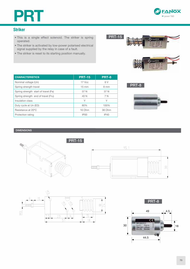
PRTStriker
• This is a single effect solenoid. The striker is spring operated.
• The striker is activated by low-power polarised electrical signal supplied by the relay in case of a fault.
• The striker is reset to its starting position manually.
CHARACTERISTICS PRT-15 PRT-8
Nominal voltage (Un) 17 Vcc 6 V
Spring strength travel 15 mm 8 mm
Spring strength start of travel (Fe) 37 N 37 N
Spring strength end of travel (Fru) 40 N 7 N
Insulation class Y Y
Duty cycle at Un (ED) 80% 100%
Resistance at 20ºC 16 Ohm 38 Ohm
Protection rating IP00 IP40
DIMENSIONS
PRT-15
PRT-8
49
44.5
4.5
30 18
PRT-15
PRT-8
73

Battery power supply module
• The KitCom is an adapter to supply SIA relays through the front communication port, allowing the communication with the computer simultaneously.
• This adapter is very useful in the commissioning processes of the transformation centres, allowing full verification of the centre, without any auxiliary power supply.
• The equipment has a microswitch that feeds the power supply with a LED (ON) when the voltage is adequate.
• In addition to all the necessary to give the power supply, this device has two LED associated with the Rx and Tx lines of communication, and they are used to verify that there is data traffic between the PC and the SIA relay.
CHARACTERISTIC
La alimentación se consigue a través de una o dos pilas, the power comes from two AA batteries placed at the bottom of the device.
SIA-C• two 1.5 Volts batteries AA type (IEC LR06)• The equipment has a small Dc/Dc power supply that
raises the voltage till the required 12 volts to operate the equipment. This operation includes the energy necessary to trip.
• With DB9 connection.
SIA-C and SIA-B• two 1.5 Volts batteries AA type (IEC LR06)• The equipment has a small Dc/Dc power supply that
raises the voltage till the required 5 volts to operate the equipment. This operation includes the energy necessary to trip.
• With USB connection.
KITCOMKITCOM
DIMENSIONS
KITCOM
1
5
VOLTAGE12 Vdc (SIA-C)5 Vdc (SIA-B)
D
U
TO EQUIPMENTDB9 MALE (SIA-C)
USB TYPE-A FEMALE (SIA-B y SIA-F)
0
D
U
M
TO PC-DB9 FEMALE (SIA-C)USB TYPE-A MALE (SIA-B, SIA-F)USB TYPE-B FEMALE (SIA-B, SIA-F)
0
3
4
BATTERY-2 X AA without cover2 X AA with cover
ADAPTATION-
Kitcom example for SIA-C with DB9 and cover.
KITCOM 1 D D 4 A VOLTAGE KITCOM1DD4A
SELECTION & ORDERING DATA
DB9 connection
USB connection
74
SICOMCommunication Software
The SICom program works with the Windows® Windows 7, Windows 8, Windows 8.1 and Windows 10 operating system and can be used to gain access to all of the relays information, to modify the settings and to save events using a graphic user interface.
The main operations that can be carried out using the SICom program are as follows:
• General data reading: Complete model, Version, Serial number, etc.
• States reading
• Measurements reading
• Reading and changing settings
• Reading and changing configuration
• Reading and deleting events
• Reading and deleting fault reports
• Reading and deleting demand current (load data profiling)
• Reading and saving oscillographic records in Comtrade format
• Changing the user passwords
• Saving and Loading settings files
• Saving and Loading configuration files
• Saving events and fault reports
• Saving demand current (load data profiling)
• Date-time synchronization
• Configuring the communication parameters
• Reading and changing counters
• Commands for opening and closing the circuit breaker and block/unblock the recloser
• Configuration of the inputs
• Configuration of the outputs
• Configuration of the causes that start a Fault Report
The update of the software does not require any user´s action, this is, if the computer is connected to Internet, SICom updates itself when it is started.
It will allow you to prepare all the settings and relay configurations without having the relay connected to the PC (offline mode), reducing engineering and commissioning time.
SICom program uses Modbus protocol, so only the ports with this protocol can be used to establish the communication.
SIC MSIA & SIL Software
75

IEC 61850
MODBUS RTU(RS-485)
e Protocolos
AB
RedBox
HSR IEDs
Redbox
SIC-ARedundancy Protocols Gateway (PRP/HSR)
Main characteristics
• SIC-A provides any-to-any protocol conversion that permit the integration of equipment with proprietary and legacy protocols in a modern infrastructure with the most recent protocols and redundant topologies.
• SIC-A can work as a multi-protocol conversor, as an unmanaged Redbox or as a redundant protocol gateway.
• SIC-A can manage upto 3000 data points of the most common protocols (Modbus, IEC 60870, DLMS, DNP3,…) or upto 800 data points of advanced protocols as IEC 61850.
• The device provides with HSR (High-availability Seamless Redundancy) is one of the chosen redundancy protocols for the substation automation as per the IEC 61850 standard. This redundancy is the evolution of the existing Parallel Redundancy Protocol (PRP).
• It is especially suited for applications that demand high availability and very short switch over time because it provides zero recovery time in case of the failure of any component. A good example of application may be the protection of automatized electrical substations or the control of synchronized drives, for instance.
Main applications
• Redbox
SIC-A Working as a Redbox allows the connection of HSR networks with traditional ones.
In case of PRP redundancy, SIC-A is not denominated Redbox, it would be a device that allows the integration into 2 independent networks through a 3rd Ethernet port.
78

• Protocol Gateway
SIC-A device is able of communicating through serial communication RS-232 or RS-485 with multiple equipment with a Master serial protocol (Modbus, IEC69870-5-101, IEC60870-5-103, DLMS…) and dispose the information into an Ethernet protocol as IEC 61850 or IEC 60870-5-104. This way, devices with conventional protocols can be integrated in Ethernet networks with advanced protocols.
• Redundant Protocol Gateway
It is the result of the combination of the functionality of a Gateway and the HSR redundancy. With this configuration, SIC-A allows the integration of equipment with serial communications in a HSR redundant network with an advanced protocol as IEC 61850 or IEC 60870-5-104.
• Most complete topology
2 SIC-A in their topology of Redbox allow connecting a HSR redundant network with another PRP network.
This is a useful application that permits to coexist new networks with existing ones.
In the same way, SIC-A in its topology of PRP Gateway, would allow to integrate serial equipment with conventional protocols in a PRP network with an advanced Ethernet protocol as IEC61850, IEC 60870-5-104, etc.
IEC
618
50 (
HS
R)
IEC 61850 (HSR)MODBUS RTU
(RS-485)
MODBUS RTU(RS-232)
HSR Gateway
HSR IEDs
Redundant Protocol Gateway
IEC 61850
MODBUS RTU(RS-485)
MODBUS RTU(RS-232)
Gateway
IEDs
Gateway de ProtocolosProtocol Gateway
79

Item Unit Value
Purpose of device - Protocol Gateway – Redbox – Protocol Redundant Gateway
Assembly (mounting) type - Mounted on standard 35 mm DIN bar and Wall mounting
Protection degree - IP20
Operating temperature range °C -40 to +85
Consumption W 6 maximum
Auxiliary Power Vdc/Vac 24*-110 / 48-230 ±20%
Weight Kg 1
Diameter of adapters on terminals mm2 0.5-2.5
Main specifications
Management EasyConnect Configuration utility
System Protocols TCP/IP, UDP/IP, SMTP, POP, HTTP, FTP, SNMP, ICMP, DHCP, BOOTP, Telnet, DNS, ARP, PPPoE, DDNS
Device Security NERC/CIP Compliant, SSHv2
Communication Security SSL based VPN tunnel using Blowfish/AES/3DES
Logic Programming AND/OR/NOT/Bit SHIFT/Split/Index support for digital and analog data, Delay operations
Network Management SNMP Agent
Protocol Support IEC 60870-5-101/103/104, DNP3 serial/TCP, Modbus RTU/ASCII/TCP, IEC 62056-DLMS, IEC 61850, IEC
61400
Supported Data Point IEC 61850: 800
DNP3, IEC 60870, Modbus and other proprietary protocols: 3000
Devices Supported 20 (10 over serial RS-485 recommended)
Serial interfaces 1 or 2 RS-485 - Terminals and/or 1 or 2 RS-232- DB9 *
Ethernet interfaces 1 RJ45 or 1 LC SFP 100Base-FX 1300nm *
HSR/PRP interfaces** 2 RJ45 or 2 LC SFP 100Base-FX 1300nm *
Time Synchronization NTC/SNTP/MEA, Protocol Specific (IEC 104,/DNP3, etc.)
RTC on-board
Redundancy** Unmanaged. Compliant implementation of both PRP (IEC 62439-3-4) and HSR (IEC 62439-3-5).
Technical specifications
Dimensions and cutout pattern SIC-A
* Model dependent
** Redundant functionality and redundant ports will be disabled if SIC-A2 model is selected
80
Selection & Ordering data
SIC-A
SIC-A Redundancy Protocols Gateway (PRP/HSR) Advanced protocol Gateway with redundancy
1
2
3
FUNCTION
Redbox
Protocol Gateway
Redundant Protocol Gateway
C
POWER SUPPLY
24*-110 / 48-230 Vdc-Vac ±20%
0
1
ETHERNET PORT
RJ45
RJ45 + SFP LC Connector
0
1
REDUNDANCY PORT
RJ45
RJ45 + SFP LC Connector
A
B
SERIAL PORTS
2 x RS232 (DB9)
RS232 (DB9) + RS-485 (Terminal)
0
1
2
REDUNDANCY TYPE
None
HSR
PRP
A
B
C
D
E
F
G
MASTER / CLIENT PROTOCOL
None
Modbus RTU
IEC 60870-5-103
DNP3.0 Serial
IEC 60870-5-101
DLMS/COSEM
IEC 61850
A
B
C
D
E
F
SLAVE/SERVER PROTOCOL
None
IEC 61850
DNP3.0 TCP/IP
IEC 60870-5-104
MODBUS TCP/IP
IEC 60870-5-101
A
ADAPTATION
-
* SIC-A Gateway using optical fiber will require a minimum voltage supply of 48 Vdc for its correct working.
2 C 0 0 B 0 B C A SIC A 2 C 0 0 B 0 B C A
81