power transformer fundamentals: design and manufacturing...generator step-up auto-transformer...
TRANSCRIPT

1
Power Transformer Fundamentals:
Design and Manufacturing
Waldemar Ziomek, Engineering Manager
CG Power Systems Canada Inc
IEEE Training, Houston, Texas,
Oct.8-9, 2013
Overview
• Transformer Design
– Transformer Types
– Construction and Parts
• Core & Coils
– Electrical design
• Losses & Impedance
• Thermal, Dielectric & Short Circuit
• Cooling & Sound Level
– Mechanical design
• Tank
• Oil Preservation
• Transformer Manufacturing Process
2
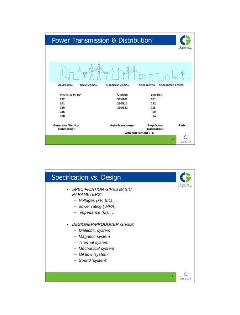
Power Transmission & Distribution
3
The traditional power supply chain - from the
central power generator to the consumer:
GENERATION TRANSMISSION SUB-TRANSMISSION DISTRIBUTION DISTRIBUTED POWER
Generator Step-Up Auto-Transformer Step-Down Pads
Transformer Transformer
115/10 or 20 kV 500/230 230/13.8
132 345/161 161
161 230/115 132
230 230/132 115
345 69
500 34
With and without LTC
Specification vs. Design
• SPECIFICATION GIVES BASIC
PARAMETERS:
– Voltages (kV, BIL) ,
– power rating ( MVA),
– impedance (IZ), …
• DESIGNER/PRODUCER GIVES:
– Dielectric system
– Magnetic system
– Thermal system
– Mechanical system
– Oil flow ‘system’
– Sound ‘system’
4

Standards USA
(ANSI) IEEE Std C57.12.00-1993, standard general requirements for liquid-immersed distribution, power and regulation transformers ~ 50 Pages
ANSI C57.12.10-1988, safety requirements 230 kV and below 833/958 through 8,333/10,417 KVA, single-phase, and 750/862 through 60,000/80,000/100,000 KVA, three-phase without load tap changing; and 3,750/4,687 through 60,000/80,000/100,000 KVA with load tap changing ~ 30+ Pages
(ANSI) IEEE C57.12.90-1993, standard test code for liquid-immersed distribution, power and regulating transformers and guide for short-circuit testing of distribution and power transformers ~ 107 Pages
NEMA standards publication no. TR1-1993; transformers, regulators and reactors ~ 2 Pages
• CSA
• IEC
5
Simple Transformer
• Left coil - input (primary coil)
– AC Source is connected to
– Magnetizing current flows and establishes the flux in core
• Right coil - output (secondary coil)
– Load
• Magnetic circuit (core)
• Problems ? Stray flux, transients, heating, vibrations, noise, losses, regulation, saturation, human errors, dielectrics (high voltage insulation), non-linear magnetics, fluid dynamics, material defects, contamination, etc.etc.
6
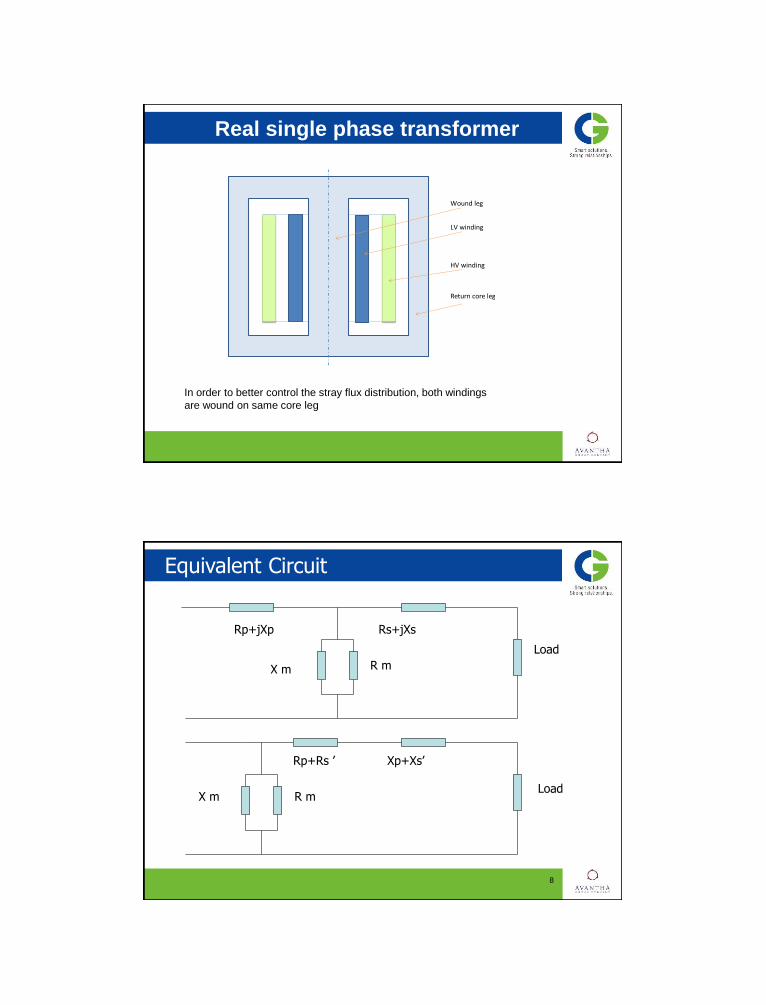
Real single phase transformer
7
Wound leg
LV winding
HV winding
Return core leg
In order to better control the stray flux distribution, both windings
are wound on same core leg
Equivalent Circuit
8
Rp+jXp Rs+jXs
X m R m
Load
Rp+Rs ’ Xp+Xs’
X m R m Load

9
Transformer Design Basis
Thermal
Dielectric Short Circuit
Quality
Reliability
Consistent performance
Long Service life
Design Procedure
• Select Core Diameter & Area (A)
• Select Maximum Flux Density (Bm)
• Find Volts/Turn = 4.44 x Freq x Bm x A
• Find LV Turns = LV volts per Phase/ (V/T)
• Find HV Turns = HV volts per Phase/ (V/T)
• Select current densities LV & HV
• Select Conductor Area = Current / Density
• Select type of Winding:
– Helical,Disc,Center-fed,end-fed
• Finalize HV Axial & Radial
• Finalize LV Axial & Radial
10

Design Procedure • Select Core - LV; LV-HV Ducts
• Draw Ampere - Turn diagram
• Find Impedance % :
α1, α2, δ - radial dimensions of two windings and the gap
lavg = π D1-2 where D1-2 = OD1+δ
• Check with guaranteed impedance, adjust V/T, height to get required impedance
• Finalize frame size- CD x WH x LC
• Find Iron Loss
• Find Load Loss
• Check for short circuit withstand
• Check for thermal withstand
• Check for impulse withstand
11
%10
339.7 421
2
aa
h
lk
S
TIfxu
avg
R
N
Nkx
h
aakR
211
Design Optimization
12
Transformer parameters
as a function of core diamater
0
20
40
60
80
100
120
140
160
180
200
700 800 900 1000 1100 1200 1300
Core diamater [mm]
Mass [
x 1
000 k
g]
0
1
2
3
4
5
6
7
8
9
10
Height [m]
Cu [ton]
Fe[ton]
Active part [ton]
Height [m]
Height
Copper
Core
Active part

Design Optimization
13
• Winding which are closer to each other have
lower impedance.
• The taller the winding – the lower the
impedance.
• Impedance is changing in power two with the
number of turns.
• Transformer impedance expressed in Ohms is
independent from MVA base
Construction Type and Main Parts
• Core- or Shell Form
• Windings – Circular for core-type , Pancake for shell-type
• Solid Insulation (turn-to-turn, section-to-section, winding-to winding, coil-to-core/clamp)
• Insulating liquid (coolant and main insulation)
• Tank
• Cooling equipment (radiators, coolers)
14

Shell Form
15
1. high voltage bushing
2. tank top section
3. cooling equipment
4. oil circulating pump
5. tank bottom section
17. pancake coil
18. inter-phase block
19. L.V. coil group
20. H.V. coil group
24. tank shielding
25. insulating washer
• Concentric windings
• ‘Set’ Winding Geometry
• Cooling options
• Cost consideration
• Shipping differences
16
Core Form

Core Form
17
Types of Cores
– 3 legs • 1 wound leg
• 2 return legs
– legs and yokes not of equal cross section
– single-phase
– 2 legs • 2 wound legs
– legs and yokes of equal cross section
– single-phase
– 3 legs • 3 wound legs
– legs and yokes of equal cross section
– three-phase
18
Type 1
Type 2
Type 3

Types of Cores cont.
– 4 legs • 2 wound legs
• 2 return legs
– legs and yokes not of equal cross section
– single-phase
– 5 legs • 3 wound legs
• 2 return legs
– legs and yokes not of equal cross section
– three-phase
19
Type 4
Type 5
20
Core Cutting
• “Core Form Design”
• Fully mitered & step lapped in corner joints
improves flux distribution, minimizes losses & sound level
• Circular core shape
provides windings with optimum radial support

Core Stacking Methods
21
BUTT-LAP STACKING:
•Local concentration of flux
•higher excitation current & core loss
STEP-LAP STACKING:
•Reduced Local flux concentration
•lower excitation current & core loss
Core Material- Grain Oriented Silicon
M - NON-LS; H - LS H
ZDKH (laser scribed)
ZDMH (mechanically scribed)
22
Tie-rod Based Clamping Systems

23
Tie-plates and Clamping Beams
• Layer / Barrel
– Mostly buried TV
– Good space factor
– Cooling only on vertical surfaces
24
Winding Types – Layer / Barrel
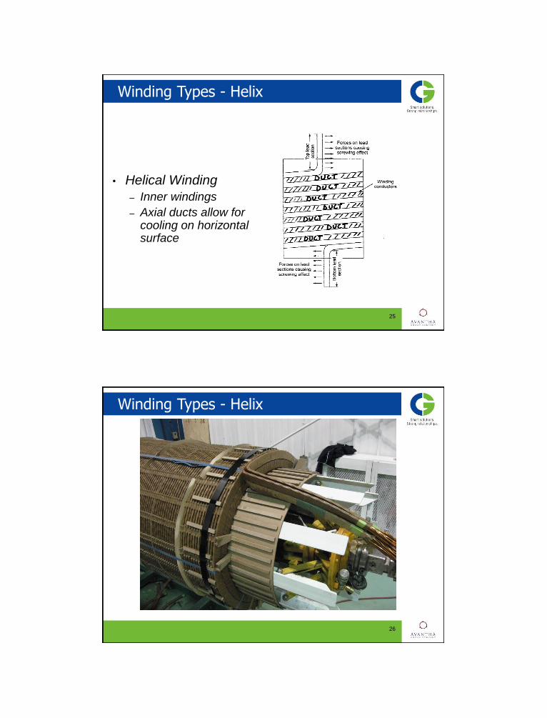
• Helical Winding
– Inner windings
– Axial ducts allow for cooling on horizontal surface
25
Winding Types - Helix
26
Winding Types - Helix

• Multistart Winding
– Used mainly for LTC taps
– Single or two layer
27
Winding Types - Multistart
He
lec
28
Winding Types - Multistart

• Tapped Disc / Helix
– Used mainly for outer LTC or DTC windings
– Can be used internally, eccentric duct
– Two symmetrical halves
– Problems with impulse
29
Winding Types – Tapped Disc / Helix
30
Winding Types – Tapped Disc / Helix

• Disc Winding
– Used for inner and outer windings
31
Winding Types – Disc Winding
32
Winding Types – Disc Winding

• Interleaved Disc Winding
– Improve impulse distribution
– Various forms of interleaving
33
Winding Types – Interleaved Disc
• Shielded Disc Winding
– Alternative to interleaving
– No joins in the winding conductor
34
Winding Types – Shielded Disc

35
Winding Types – Shielded Disc
36
Magnet Wire, Paper Insulated

CTC - Epoxy Bonded, Netting Tape
37
Losses & Impedance
• No – load losses:
– Hysteresis and eddy losses in transformer core
• Load losses:
– DC Losses
• Resistive loss in winding conductor
– Eddy Losses
• Produced by stray flux in the windings when current is drawn
from the transformer
– Stray Losses
• Eddy losses in constructional parts (clamps, tank wall, etc)
• Impedance
– Dependent upon geometry, amp-turns, base
power rating and frequency
– Effect on short circuit currents/forces
38

39
Eddy Losses in Conductor
2222
97
3
2
6
,3
;cos
sin
10967.20;104;;2
;2
22
:
m
eddy
meddy
BdfV
P
thend
dfor
ch
sh
mm
Hdf
where
m
WB
V
P
volumeofunitperfactorlossEddy
d
Bm
Sound Level
• Magnetostriction - varying magnetic flux produces
vibrations at fundamental frequency of 120 Hz for
60Hz power frequency ( or 100 Hz at 50Hz power)
• Sound level depends on:
- core material
- flux density in core
• - core weight - sound level increases
proportionally to log (weight),
- tank design and cooling system (# and type of
fans, pumps)
• Measured at 0.3 m for core alone and at 2 m for top
rating (with whole cooling equipment on)
• Sound level under load becoming a new requirement
40

41
Stray Flux Distribution
LV HV
CORE
42
Stray Flux Distribution
Flux distribution with the tapping winding in position:
(i) full rise, (ii) neutral, (iii) full buck

43
Stray flux distribution – controlling the eddy loss by varying conductor size
LTC Line Valve
• Stress due to radial forces:
– Hoop on outer winding
– Buckling on inner winding
– Radial bending
• Stress due to axial forces:
– Compressive on keyspacer
– Tilting of conductors
– Axial bending between keyspacers
• Spiralling forces
44
Mechanical Forces in Windings

Losses in Tank Wall
45
Losses in Constructional Parts
46

Insulation Coordination & Design Impact
47
Withstand voltage Impact on design
BIL (LI) Bushings, lead structure & its clearances,
winding clearances, stresses to ground,
neutral point insulation
SIL External clearances, lead clearances,
phase-to-phase stresses
Induced voltage Internal winding stresses (V/T), stresses
to ground, phase-to-phase stress
Applied voltage Stresses to ground (windings, leads)
Electric Field Intensity in Hi-Lo Gap
48
Comparison With Weidmann Curves
49
1
10
100
0.1 1 10 100
Distance (mm)
Gra
die
nt
(kV
/mm
)
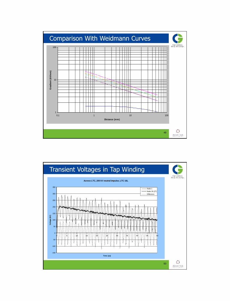
Transient Voltages in Tap Winding
50
Across LTC, 200 kV neutral impulse, LTC 16L
-150
-100
-50
0
50
100
150
200
250
300
350
0 5 10 15 20 25 30 35 40 45 50
Time (us)
Vo
ltag
e (
kV
)
Node 1
Node 26 (27)
Difference
51
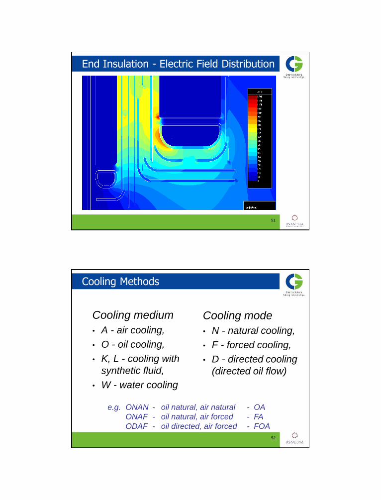
End Insulation - Electric Field Distribution
Cooling Methods
Cooling medium
• A - air cooling,
• O - oil cooling,
• K, L - cooling with
synthetic fluid,
• W - water cooling
Cooling mode
• N - natural cooling,
• F - forced cooling,
• D - directed cooling
(directed oil flow)
52
e.g. ONAN - oil natural, air natural - OA
ONAF - oil natural, air forced - FA
ODAF - oil directed, air forced - FOA

Directed and Non-Directed Oil Flow
53
Directed Non - Directed
Cooling
A) ONAN, OA
- Oil natural, air natural
B) ONAF, FA
- Oil natural, air forced
C) OFAF, FOA
- Oil forced, air forced
54

Cooling
D) ODAF, FOA
- Oil directed, air forced
- The oil is pumped and
directed through some
or all of windings
E) OFWF, FOW
- Oil forced, water forced
F) ODWF, FOW
- Oil directed, water
forced
55
Tap Changers
• Load tap changers (LTC)
• De-energized type changers (DETC)
• Bridging
• Linear
• Series/parallel
• Delta/wye
56

DETC
Typically in HV w/adjustment of ±5%, 4 steps
57
Bridging Type Linear Type
LTC
• (On) Load Tap Changer - switching under load!
• L.T.C. Switches - Resistive Bridging
- Current limiting resistors
- Reactive Bridging
- Preventative auto-transformer (reactors)
• On tank & In tank
• Vacuum or Arcing in oil
58

Resistive - Type LTC
59
Position 1. The main contact H is carrying the load current. The transition contacts M1
and M2 are open, resting in the spaces between the fixed contacts.
Fig. a Fig. b
Fig. c Fig. d
Fig. e
The transition contact M2 has made on the fixed contact 1, and the main switching contact H has broken. The transition resistor and the transition contact M2 carry the load current.
The transition contact M1 has made on the fixed contact 2. The load current is divided between the transition contacts M1 and M2. The circulating current is limited by the resistors.
The transition contact M2 has broken at the fixed contact 1. The transition resistor and the transition contact M1 carry the load current.
Position 2. The main switching contact H has made on the fixed contact 2. The transition contact M1 has opened at the fixed contact 2. The main contact H is carrying the load current.
Reactor-type LTC
60
tap n tap n+1
P1 P4
P3 P2 P
V
I
IL
2 IL
2
CT
tap n tap n+1
P
P1 P4
P3 P2
IL
2
IL
2
CT
Non - Bridging Bridging
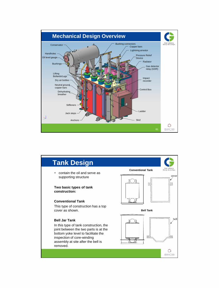
Mechanical Design Overview
61
Bushing connectors
Lightning arrestor
Radiator
Conservator
Pressure Relief
Device
Dry air bottles
Dehydrating
breather
Control Box
Skid
Bushings
Lifting
Bollards/Lugs
Jack steps
Anchors
Stiffeners
Copper bars
Handholes
Impact
recorder
Ladder
Oil level gauge
Neutral ground
copper bars
Gas detector
relay (GDR)
62
Tank Design
Two basic types of tank
construction:
Conventional Tank
This type of construction has a top
cover as shown.
Bell Jar Tank
In this type of tank construction, the
joint between the two parts is at the
bottom yoke level to facilitate the
inspection of core-winding
assembly at site after the bell is
removed.
Conventional Tank • contain the oil and serve as
supporting structure
Bell Tank

63
The transformer tank should
be capable of withstanding the
following loads:
1. Vacuum
• Maximum allowable
deflection for the tank is
0.005 x span length
2. Lifting
• designed to facilitate
handling of the transformer.
• Lifting bollards/lugs are
used to lift the structure by
a crane
Tank Design Lifting Bollard
Bollard
Lug
Lifting Lug
Lifting Lug
64
Jack Step Gussets
Tank Wall
Jacking pad
Tank Design
3. Jacking
• designed to facilitate
handling of the
transformer.
• used for handling the
transformer in the
absence of crane,
especially at the site

65
4. Seismic and wind load:
• The transformer has to be designed for a specified seismic
acceleration and wind load.
• are very important design considerations for bushings, supporting
structures of conservator and radiators.
5. Transient pressure rise
• When an internal fault takes place, a large volume of decomposed
gases may get generated due to arcing.
• Under these conditions, the tank structure has to withstand a rapid
rise of pressure.
Tank Design
Sound Reduction
Other consideration to take into account when designing tank is to
reduce sound generation
66
Tank Design
Base of Tank
• can be stiffened by formed channels or c-channels to reduce its thickness
• Designed to carry core-winding assembly weight, oil head and test pressure
Flat Base
Skid Base
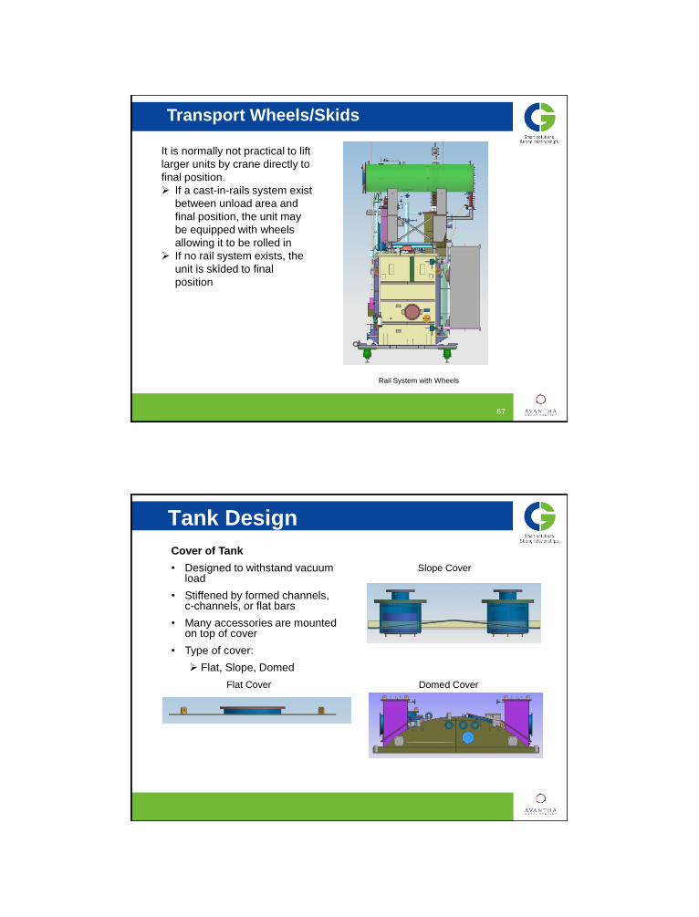
Transport Wheels/Skids
67
It is normally not practical to lift
larger units by crane directly to
final position.
If a cast-in-rails system exist
between unload area and
final position, the unit may
be equipped with wheels
allowing it to be rolled in
If no rail system exists, the
unit is skided to final
position
Rail System with Wheels
68
Tank Design Cover of Tank
• Designed to withstand vacuum load
• Stiffened by formed channels, c-channels, or flat bars
• Many accessories are mounted on top of cover
• Type of cover:
Flat, Slope, Domed
Flat Cover Domed Cover
Slope Cover
69
Stiffener
55
The design of stiffeners is a very important
aspect of tank design
• An effective stiffening arrangement can
reduce the tank plate thickness.
Thus, tank weight is minimum.
• should be able to withstand the specified
loads
Types of stiffeners used
• Formed channels
• Angles
• Bars
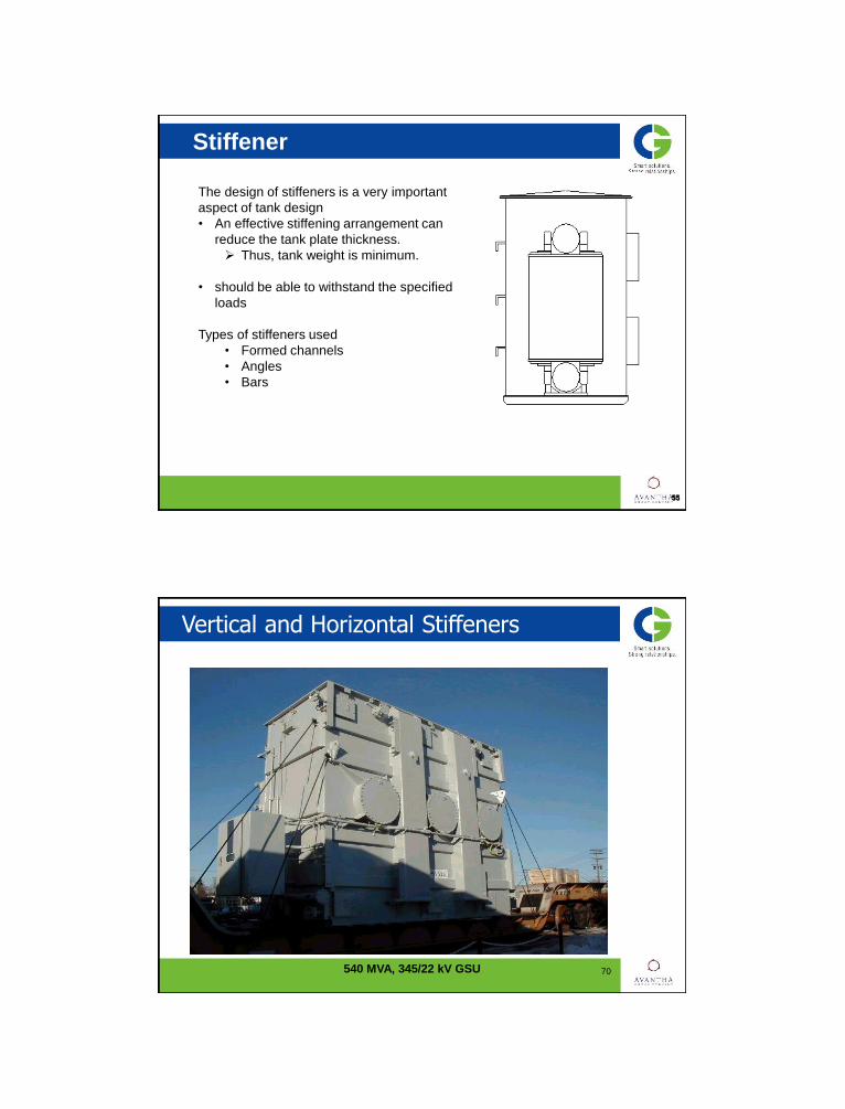
Vertical and Horizontal Stiffeners
70 540 MVA, 345/22 kV GSU

Oil Preservation Systems
71
GAS-OIL SEALED
• Free space (nitrogen gas or dry air) is
provided in the tank for oil expansion
• The contact of oil with the outside
atmosphere is totally eliminated.
• A positive pressure of 0.5 to 5 psi
• Advantage
Simple design, no conservators
• Disadvantage
Maintenance of gas system
Possibility for gas bubble
generation, which reduces the
dielectric strength
• Can only designed for a transformer
up to 550 KV BIL
72
Oil preservation system Conservator System
Oil Preservation Systems
• Connected to transformer tank by piping.
• Can be provided with air bag
• Air bag
A synthetic rubber bag
occupies the space above oil to prevent
air from contacting the oil
Internal of the bag is connected to
atmosphere
Breathe in air when transformer cools
and the oil volume is reduced
breathe out when transformer heats up.
• Air typically enters and exits through a
desiccant-type air dryer/breather
• The main parts of the system are the
expansion tank, air bag, breather, vent
valves, liquid-level gauge, and alarm switch
73
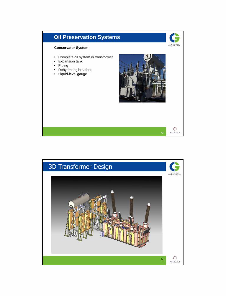
Oil Preservation Systems
• Complete oil system in transformer
• Expansion tank
• Piping
• Dehydrating breather,
• Liquid-level gauge
Conservator System
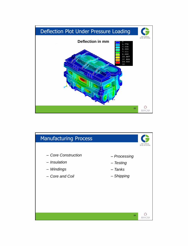
3D Transformer Design
74

75
Transformer Product Visualization in UG
• Downstream Visualization in Shop & Supplier
• Reduce/Eliminate 2-D Drawings
• Improve feedback mechanism
• Eliminate non value added activities on clarifications
Design Example – HV Internal
76

Design Example – LV Internal
77
Design Example – HV External
78

Design Example – LV External
79
80
Finite Element Model - Deformation

81
Finite Element Model – Safety Factor
82
Finite Element Model – Equivalent Stress
83
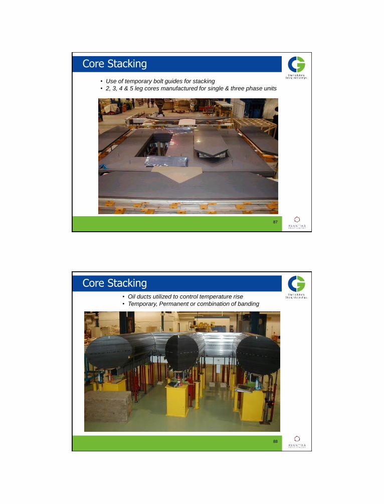
Deflection Plot Under Pressure Loading
Deflection in mm
– Core Construction
– Insulation
– Windings
– Core and Coil
84
Manufacturing Process
– Processing
– Testing
– Tanks
– Shipping

Core Cutting – Georg 1000
85
86
Core Parts (Legs and Yokes) Stacked
87
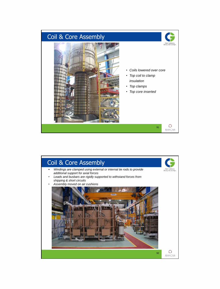
Core Stacking
• Use of temporary bolt guides for stacking
• 2, 3, 4 & 5 leg cores manufactured for single & three phase units
88
Core Stacking • Oil ducts utilized to control temperature rise
• Temporary, Permanent or combination of banding

89
Coil Assembly
• Winding type
• Conductor Type
• Insulation components
90
Complete Winding Insulation Package
91
Coil & Core Assembly
• Coils lowered over core
• Top coil to clamp
insulation
• Top clamps
• Top core inserted
92
Coil & Core Assembly • Windings are clamped using external or internal tie rods to provide
additional support for axial forces
• Leads and busbars are rigidly supported to withstand forces from
shipping & short circuits
• Assembly moved on air cushions

Tank Shop
93
• Cleaned, priming and painted
• Inside painted white
• Shunt Packs
540 MVA, 345/22 kV GSU
Tank Covers
94
• Raised flanges
• Domed cover
• Mild steel plate w/Inserts
95
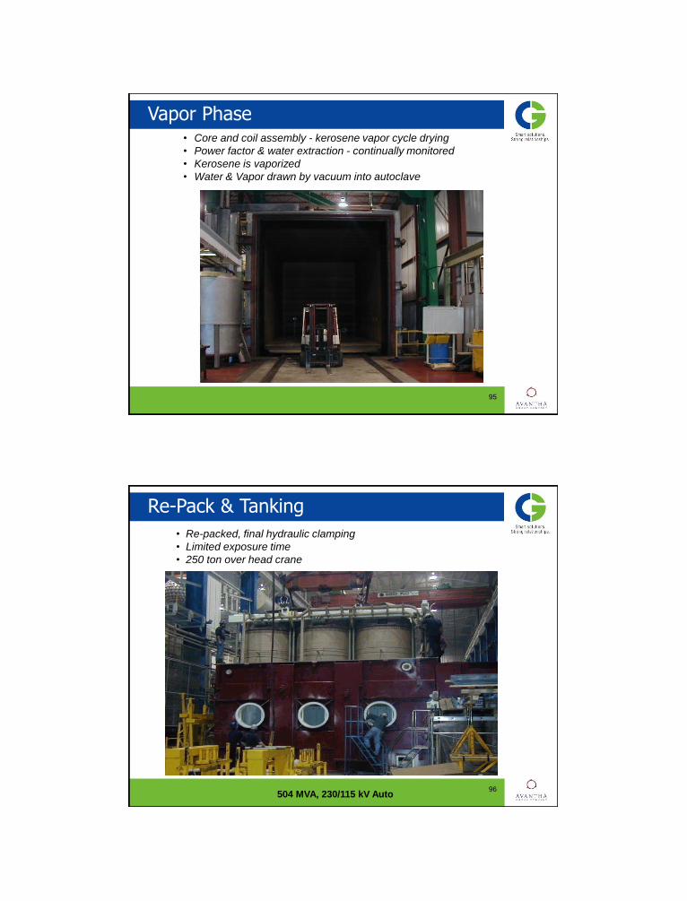
Vapor Phase • Core and coil assembly - kerosene vapor cycle drying
• Power factor & water extraction - continually monitored
• Kerosene is vaporized
• Water & Vapor drawn by vacuum into autoclave
96
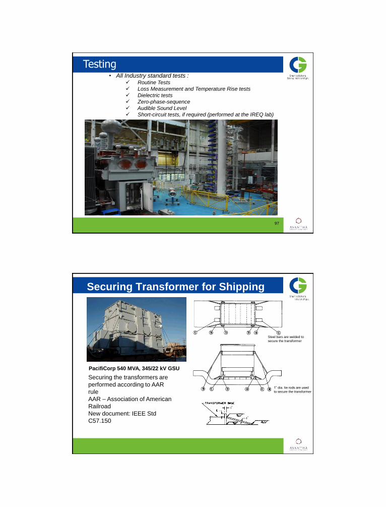
Re-Pack & Tanking
• Re-packed, final hydraulic clamping
• Limited exposure time
• 250 ton over head crane
504 MVA, 230/115 kV Auto
Testing
97
• All Industry standard tests : Routine Tests
Loss Measurement and Temperature Rise tests
Dielectric tests
Zero-phase-sequence
Audible Sound Level
Short-circuit tests, if required (performed at the IREQ lab)
98
Securing Transformer for Shipping
PacifiCorp 540 MVA, 345/22 kV GSU
Steel bars are welded to
secure the transformer
1” dia. tie rods are used
to secure the transformer
Securing the transformers are
performed according to AAR
rule
AAR – Association of American
Railroad
New document: IEEE Std
C57.150

IEEE Std C57.150-2012 Guide for transportation
99
IEEE Guide for the Transportation of Transformers and Reactors Rated 10,000 kVA or Higher – major topics covered are as follows:
• Request for quotation and specification • Design Considerations for Transport • Transportation preparation (Main transformer or reactor, tank
accessories) • Planning for heavy haul transportation • Transport (Transportation information, terminology, Barge and ocean
vessels, Rail, Air cargo, Arrival at destination , dielectric fluid) • Heavy haul transportation (Condition of heavy haul equipment,
Inspection of equipment prior to receiving, Offloading the equipment onto heavy haul transportation equipment, Securing the load, Transportation to the destination )
• Arrival (receipt) inspection
IEEE 57.150 – six degrees of motion at sea
100
Vessels underway at sea will experience wind and wave conditions that cause six
degrees (or freedoms) of motion.
Three degrees of motion are rotational: the side to side rotation is called “roll,”, the fore
to aft rotation causing the bow to rise and fall opposite to the stern rising and falling is
called “pitch,” while turning or rotation about the vertical axis is called “yaw.”
Three degrees are linear or axial: In combination or separately, the vessel may
experience forth to aft acceleration/deceleration called “surge”, sideways movement
called “sway,” and ”, vertical movement called “heave”.

IEEE 57.150 – design aspects
101
‘ The design and shipping details of new transformers and reactors should
be addressed during the design phase and prior to the manufacture to
address all aspects of transport from factory to final pad. The equipment
should be designed to allow transportation by both rail and truck, as well as
by ocean vessel, barge, or air cargo when appropriate.
The core legs should have a solid support from the bottom to the top
clamp to prevent sideways deformation and bulging of the outermost
laminations. The core should be adequately braced to the core clamping
structure, so that it cannot move in any direction. The windings should be
tight to prevent movements relative to the core. The core and coil assembly
and other internal components should be supported by permanent bracing
to the interior of the tank. Temporary transportation braces for the core and
coil should not generally be required, and should only be allowed with
special approval and instructions for use formally documented.
Temporary transportation supports may be required in some units (e.g.
units that will be subjected to long sea voyages, shell form, or other units
shipped in a laid down position), or for current transformers, leads, bushing
supports, and other ancillary items.’
Schnable – Road Trailer
102
103
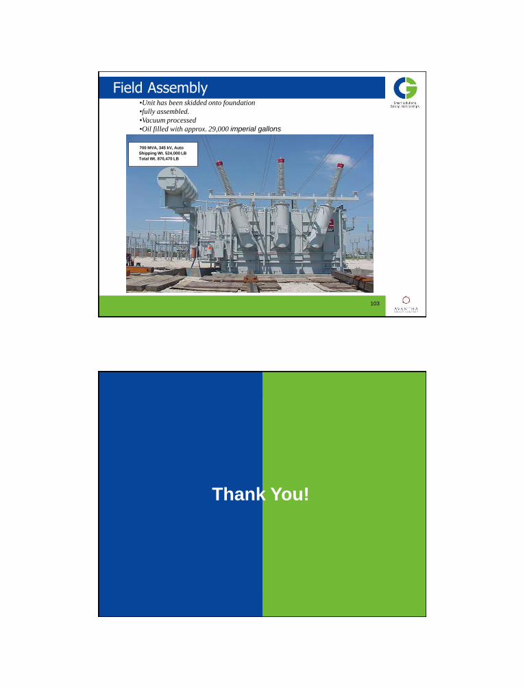
•Unit has been skidded onto foundation
•fully assembled.
•Vacuum processed
•Oil filled with approx. 29,000 imperial gallons of oil
700 MVA, 345 kV, Auto
Shipping Wt. 524,000 LB
Total Wt. 870,470 LB
Field Assembly
104
Thank You!