power transmission engineering - spring 07 · geartechnology.com e-mail newsletter • e-gt ......
TRANSCRIPT

w w w . p o w e r t r a n s m i s s i o n . c o m
Products• High-Capacity Bearings
• Plastic Couplings
• Servo Drives
powertransmissionengineeringpowerpowertransmissionengineeringPTE SPRING 2007
Features• PTDA Brings
Industry Together
• Replacing Motors,Counting Savings

PRECISION. POWER. PERFORMANCE.PRECISION. POWER. PERFORMANCE.PRECISION. POWER. PERFORMANCE.The Rexnord PromiseThe Rexnord Promise
www.rexnord.com 866-REXNORD
For more than 100 years,For more than 100 years,Rexnord has deliveredRexnord has deliveredprecision, power andprecision, power andperformance – with a focus onperformance – with a focus onexcellence in quality andexcellence in quality andservice – to the Powerservice – to the PowerTransmission industry aroundTransmission industry aroundthe world.
Rexnord’s precision is not onlyis not onlyreflected in our engineering,reflected in our engineering,development andmanufacturing, but also in howmanufacturing, but also in howwe deal with you, our customer. we deal with you, our customer.
With Rexnord’s seamlessWith Rexnord’s seamlessacquisition of FalkTMTM, coupled, coupledwith the strength of thewith the strength of theRexnord® and Link-Beltand Link-Belt® brands,brands,
we are positioned to bring morewe are positioned to bring morewe are positioned to bring morepowerpower to the powerto the powertransmission industry than evertransmission industry than evertransmission industry than everbefore. The breadth and depthbefore. The breadth and depthof the Rexnord product portfolioof the Rexnord product portfolioprovides you with unrivaledprovides you with unrivaledselection and supportselection and supportselection and support
PerformancePerformancePerformance is the ultimateis the ultimatepromise to which Rexnord ispromise to which Rexnord ispromise to which Rexnord iscommitted. Go ahead. Measurecommitted. Go ahead. Measurecommitted. Go ahead. Measureour performance on the basis ofour performance on the basis ofour performance on the basis ofhow our equipment operates,how our equipment operates,our dependability, ourour dependability, ourcommunication, and ourcommunication, and ourresponsiveness. You will see forresponsiveness. You will see foryourself that we deliver on ouryourself that we deliver on ourpromise.promise.
Precision. Power. Performance. Precision. Power. Performance. Precision. Power. Performance. Call 866-REXNORD today to find out more!Call 866-REXNORD today to find out more!Call 866-REXNORD today to find out more!
Rexnord is a registered trademark, and Falk is a trademark of Rexnord Industries, LLC.Rexnord is a registered trademark, and Falk is a trademark of Rexnord Industries, LLC.Link-Belt is a registered trademark of the Link-Belt Construction Equipment Company.Link-Belt is a registered trademark of the Link-Belt Construction Equipment Company.
Geared Products FlatTop Chain Couplings Bearings
Industrial Chain andConveying Equipment

C o n t e n t s S P R I N G
2 0 0 7
www.powertransmission.com spring 2007 powertransmissionengineering 1
Interview:PTDA Boosts Power Transmission and Motion Control Industry 16
Next-Generation BearingsThe SKF High-Capacity Cylindrical Roller Bearing 18
Replacing Motors, Counting SavingsResults from a 100-Motor Study: Part I of III 26
CouplingsPlastic Replacing Metal in Coupling Applications 32
Servo DrivesServo-Driven, Shaftless Flexography Streamlines the Printing Industry 36
FEATURES
powertransmissionengineeringpowertransmissionengineeringPTE

2 powertransmissionengineering spring 2007 www.powertransmission.com
Product News The latest power transmission products 5Events Calendar 40Industry News The latest news from the power transmission industry 42Classifieds Our product and service marketplace
47Advertiser Index Contact information for companies in this issue 48
DEPARTMENTS
C o n t e n t s
• Power Transmission Engineering Sign up for a free subscription to our new magazine
• FIND-IT WIZARD Let us help you find the components you need. It's fast, easy and free.
• BUYERS GUIDE Search for power transmission pro- ducts and services and communicate with the industry's leading suppliers
ON L I N E
powertransmission.com
• BUYERS GUIDE Search for gear industry products and services and communicate with the industry’s leading suppliers
• SUBSCRIPTIONS Sign up for subscriptions to Gear Technology and the geartechnology.com e-mail newsletter
• E-GT Subscribers get access to back issues of Gear Technology
Randall Publishing makes every effort to ensure that the processes described in POWER TRANSMISSION ENGINEERING conform to sound engineering practice. Neither the authors nor the publisher can be held responsible for injuries sustained while following the procedures described. Postmaster: Send address changes to POWER TRANSMISSION ENGINEERING, 1425 Lunt Avenue, P.O. Box 1426, Elk Grove Village, IL, 60007. ©Contents copyrighted by RANDALL PUBLISHING, INC., 2007. No part of this publication may be reproduced or transmitted in any form or by any means, electronic or mechanical, including photocopying, recording, or by any information storage and retrieval system, without permission in writing from the publisher. Contents of ads are subject to Publisher’s approval.
C o n t e n t s S P R I N G
2 0 0 7powertransmissionengineeringpowertransmissionengineeringPTE

For More Information:10761 Ahern Avenue S. E. • Watertown, MN. 55388
Phone: 952-955-2626 • Fax: 480- 247-4096
www.midwestmotion.com
Design, Manufacturing & Distribution —Motion Control Equipment
• Brushed & Brushless Gearmotors & Servo Motors available from STOCK –
• DC Servo Motors & Gearmotors equipped with integral Brakes and Encoders
• Finished Inventory Report ON LINE at www.midwestmotion.com/inventory
• DC Linear Actuators, DC Power Supplies, Motor Controls & Servo Amps from STOCK!
• Products well suited for most Electric Vehicle Applications – UGV’s; Military Robotics
MADE IN
U.S.A.
Providing Quality Brushed and Brushless DC Servo Motors, Planetary Gearmotors, Servo Amplifi ers, Sealed (IP-65) DC Motor Speed Controls, 12V,
24V & 48V DC Power Supplies, and DC Linear Actuators w/Pot Feedback

EDITORIALPublisher & Editor-in-Chief Michael Goldstein
[email protected] Editor William R. Stott
[email protected] Editor Jack McGuinn [email protected] Editor Assistant Editor Assistant Editor Robin Wright
[email protected] Consultant Editorial Consultant Editorial Consultant Paul R. GoldsteinTechnical Editors Robert Errichello, Don McVittie, Robert E. Smith, Dan Thurman
ARTArt Director Art Director Art Director Kathleen O'Hara
ADVERTISINGAdvertising Sales Manager Advertising Sales Manager Advertising Sales Manager Ryan King
CIRCULATIONCirculation Manager Circulation Manager Circulation Manager Carol Tratar
INTERNETWeb Developer Dan MacKenzie
RANDALL PUBLISHING STAFFPresident Michael GoldsteinPresident Michael GoldsteinPresidentVice President Richard GoldsteinVice President Richard GoldsteinVice PresidentAccounting Luann HarroldAccounting Luann HarroldAccounting
VOL. 1, NO. 2
Randall Publishing, Inc.1425 Lunt AvenueRandall Publishing, Inc.1425 Lunt AvenueRandall Publishing, Inc.
P.O. Box 1426Elk Grove Village, IL 60007
Phone: 847-437-6604Fax: 847-437-6618
4 powertransmissionengineering spring 2007 www.powertransmission.com
CompleteLinear Axis DriveSolutionsAchieve a compact linear axisdrive by combining ourPrecision Servo Reducerswith our Standard Rangeof Rack & Pinion Drives.
Choose from Helical & Straight versions, in anassortment of materials,sizes and quality levels,to meet almost any axisdrive requirements.
ATLANTA Drive Systems, Inc.Call Toll-Free at: (800) 505-1715
Or Visit Us at: www.atlantadrives.com
The World Leader inRack & Pinion Drive
Technologies
MIDWEST GEARMIDWEST GEAR& TOOL, INC.
15700 Common Rd.Roseville, MI 48066
CONTACT:CRAIG D. ROSS(586) 779-1300
FAX (586) [email protected]@[email protected]
w w w . p o w e r t r a n s m i s s i o n . c o m
Products• High Capacity Bearings
• Plastic Couplings
• Servo Drives
powertransmissionengineeringpowerpowertransmissionengineeringPTE SPRING 2007
Features• PTDA Brings
Industry Together
• Replacing Motors,Counting Savings
powertransmissionengineeringpowertransmissionengineeringPTE
Cover photocourtesy ofRevolvo Ltd.
www.powertransmission.com spring 2007 powertransmissionengineering 5
product news
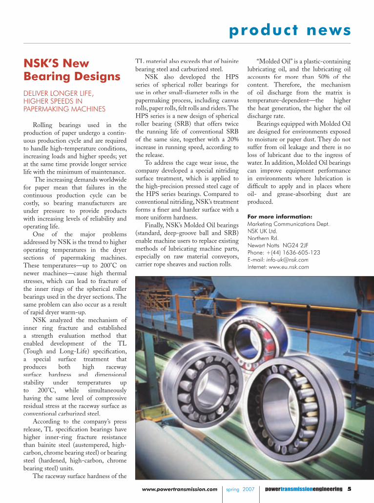
NSK’S New Bearing DesignsDELIVER LONGER LIFE, HIGHER SPEEDS IN PAPERMAKING MACHINES
Rolling bearings used in the production of paper undergo a contin-uous production cycle and are required to handle high-temperature conditions, increasing loads and higher speeds; yet at the same time provide longer service life with the minimum of maintenance.
The increasing demands worldwide for paper mean that failures in the continuous production cycle can be costly, so bearing manufacturers are under pressure to provide products with increasing levels of reliability and operating life.
One of the major problems addressed by NSK is the trend to higher operating temperatures in the dryer sections of papermaking machines. These temperatures—up to 200°C on newer machines—cause high thermal stresses, which can lead to fracture of the inner rings of the spherical roller bearings used in the dryer sections. The same problem can also occur as a result of rapid dryer warm-up.
NSK analyzed the mechanism of inner ring fracture and established a strength evaluation method that enabled development of the TL (Tough and Long-Life) specifi cation, a special surface treatment that produces both high raceway surface hardness and dimensional stability under temperatures up to 200°C, while simultaneously having the same level of compressive residual stress at the raceway surface as conventional carburized steel.
According to the company’s press release, TL specifi cation bearings have higher inner-ring fracture resistance than bainite steel (austempered, high-carbon, chrome bearing steel) or bearing steel (hardened, high-carbon, chrome bearing steel) units.
The raceway surface hardness of the
TL material also exceeds that of bainite bearing steel and carburized steel.
NSK also developed the HPS series of spherical roller bearings for use in other small-diameter rolls in the papermaking process, including canvas rolls, paper rolls, felt rolls and riders. The HPS series is a new design of spherical roller bearing (SRB) that offers twice the running life of conventional SRB of the same size, together with a 20% increase in running speed, according to the release.
To address the cage wear issue, the company developed a special nitriding surface treatment, which is applied to the high-precision pressed steel cage of the HPS series bearings. Compared to conventional nitriding, NSK’s treatment forms a fi ner and harder surface with a more uniform hardness.
Finally, NSK’s Molded Oil bearings (standard, deep-groove ball and SRB) enable machine users to replace existing methods of lubricating machine parts, especially on raw material conveyors, carrier rope sheaves and suction rolls.
“Molded Oil” is a plastic-containing lubricating oil, and the lubricating oil accounts for more than 50% of the content. Therefore, the mechanism of oil discharge from the matrix is temperature-dependent—the higher the heat generation, the higher the oil discharge rate.
Bearings equipped with Molded Oil are designed for environments exposed to moisture or paper dust. They do not suffer from oil leakage and there is no loss of lubricant due to the ingress of water. In addition, Molded Oil bearings can improve equipment performance in environments where lubrication is diffi cult to apply and in places where oil- and grease-absorbing dust are produced.
For more information:Marketing Communications Dept.NSK UK Ltd.Northern Rd.Newart Notts NG24 2JFPhone: +(44) 1636-605-123E-mail: [email protected]: www.eu.nsk.com

product news product news
6 powertransmissionengineering spring 2007 www.powertransmission.com spring 2007 transmission
Ruland Manufacturing’s CouplingsRESISTANT TO WIND-UP
Ruland Manufacturing offers oldham couplings and zero-backlash jaw couplings with standard keyways as stock items. Keyways increase the torque capacity of the coupling by creating a positive drive while also ensuring
precise positioning of the coupling hub. Oldham couplings and jaw couplings are each three-piece coupling assemblies comprised of two aluminum hubs with a mating center section for transmission of torque. The design offers simplifi ed assembly and can mix and match hubs with different bores, even inch-to-metric combinations.
According to the company’s press release, oldham and jaw couplings differ in performance.
Oldham coupling hubs have drive tenons that do not overlap when combined with the mating center disc. This design allows for easier sliding to accommodate misalignment with light bearing loads since the only resistance caused by misalignment is frictional. The couplings also operate as a mechanical fuse since the hubs will spin freely if the center disc fails and offers electrical isolation.
By contrast, zero-backlash jaw couplings have “jaws” that overlap when combined with their mating center
spider. Jaws will stay engaged even if the spider fails. Spiders are made of an advanced polyurethane material and available in three different hardness levels to provide varied levels of shock absorption. Ruland jaw couplings have a curved jaw profi le and press fi t to provide zero-backlash. Standoffs, located on the spider “limbs,” assist in angular misalignment capabilities, as well as electrical isolation.
Ruland oldham couplings and jaw couplings are offered in a choice of six outside diameters from 1/2" (13 mm) to 2 ¼" (57 mm) in both set-screw style and clamp style. A large variety of inch and metric bore sizes starting at 1/8" (3 mm) is available with keyways offered on 3/8" (8 mm) and larger bores.
For more information:Ruland Manufacturing Co.6 Hayes Memorial Dr.Marlborough, MA 01752Phone: (508) 485-1000E-Mail: [email protected]
Danaher MotionUPDATES CONTROL PLATFORM FOR AUTOMATED GUIDED VEHICLES
Danaher Motion introduces version 1.4 of its NDC8 control platform for NDC8 control platform for NDC8automated guided vehicles (AGVs). The NDC8 control platform now supports NDC8 control platform now supports NDC8
up to 10 AC drives per AGV. According to Danaher’s press release,
drives can be used for steering, driving or auxiliary control, and AC technology helps increase power while reducing running costs.
“NDC8 version 1.4 hosts an NDC8 version 1.4 hosts an NDC8industry-standard OPC client, allowing for a smooth connection to any I/O resource on the market,” says Henrik Eriksson, strategic product line manager for Danaher Motion’s AGV family of products. “The updated curve-editing tool gives the engineer the freedom to adapt each AGV layout, and new spline-based fl exible curves allow for increased vehicle speed at corners, while saving fl oor space when negotiating tight corners. The improved tool set provides statistical data to optimize overall transport fl ow and increase system productivity.”
Additionally, the route-planning tool set has been enhanced and helps users to limit and avoid AGV traffi c congestion problems. Ladder Diagram
language has been added to the NDC8 PLC programming environment, PLC programming environment, PLCOpenPCS, for even more fl exibility in customizing AGV solutions.
Magnetic spot or magnetic tape navigation can be combined effortlessly and seamlessly with existing laser navigation systems. Combining navigation techniques is particularly useful in environments where neither is optimal for all of the pre-programmed routes of a plant.
Danaher Motion’s AGV solutions are used in the steel, automotive, electronics, ceramics, paper and printing, food and beverage, logistics and distribution, and entertainment industries.
For more information:Danaher Motion1500 Mittel Blvd.Wood Dale, IL 60191 Phone: (540) 633-3400E-mail: [email protected]: www.DanaherMotion.com

product news product news
transmission spring 2007 www.powertransmission.com spring 2007 powertransmissionengineering 7
www.hilliardcorp.com
Industrial Clutches and BrakesAt Hilliard, we’ve built a reputation on solving motion control problems. We are structured so that you receive direct contact with our engineers for important consulta-tions. Special designs that fall outside standard product lines are met economically and efficiently.
Since 1905 we’ve been working with our customers to solve their motion control problems. We’re confident that together we can arrive at a solution to your problem, too.
Portescap’s Linear ActuatorsCAPABLE OF PRECISE POSITIONING
Portescap, a Danaher Motion company, introduces 26DAM series digital linear actuators. These units provide linear force up to 120 oz. (33 N), linear step resolution of 0.001", 0.002" and 0.004" and 3.4 watts of power.
“The 26DAM is an ideal linear actuator solution in medical equipment applications such as pumps, pipettes and scanners, as well as instrumentation and valve applications,” says Dave Beckstoffer, Portescap product manager.
These linear actuators are available These linear actuators are available in captive and non-captive versions, with in captive and non-captive versions, with uni-polar or bi-polar coil construction, uni-polar or bi-polar coil construction, and industry-standard frame sizes. Customized designs are available upon request.
For more information contact:For more information contact:Danaher Motion1500 Mittel Blvd.1500 Mittel Blvd.Wood Dale, IL 60191 Phone: (540) 633-3400E-mail: [email protected]: www.danahermotion.com

product news
Revolvo’s Dimensionally Interchangeable Split Plummer Blocks
DELIVER DOWNTIME REDUCTIONS FOR BEARING USERS
Revolvo’s new SN and SD series SRB Split Roller Bearing units provide a retrofi t solution, which offers full dimensional interchangeability with conventional SN & SD series plummer blocks and requires no dimensional or major structural changes to customers’ machinery, according to the company’s
addition, they have a new design of cage clip, which is retained via spiral pins to one-half of the cage during assembly and disassembly. With this retained design, the maintenance engineer benefi ts from a “free hand,” which speeds up the bearing replacement process.
SRB bearing units are designed to be statically self-aligning. This means that there is no need to accurately realign the bearing housing to the shaft or any other in-line equipment during the installation. Secondly, SRB split roller bearings can accommodate thermal expansion of the shaft within the bearing envelope itself. Third, SRB split roller bearings perform reliably in environments up to 140°C. They are also suitable for use in aggressive environments due to the performance of the sealing systems available.
In fact, the SRB product has a spherical location between the cartridge housing and pedestal support, ensuring that, under conditions of shaft misalignment, the seals always remain concentric to the shaft. As a result, SRB split roller bearing units perform well in harsh operating conditions, even with shaft misalignment, whereas solid mounted bearings can suffer from non-concentric ineffective seals that will lead to premature bearing failure.
Finally, the SN and SD series split bearings can be inspected at regular intervals, as part of a planned maintenance campaign. Revolvo’s design provides “pry” slots which enable disassembly of the cartridge housing and support pedestal, reducing the likelihood of components being broken, especially in applications where the bearing unit has been installed for some time, and/or where the environment is contaminated.
For more information:Revolvo Ltd. Queens CrossDudley, West Midlands DY1 1QWU.K.Phone: +(44) 1384-844000 Internet: www.revolvo.com
press release.In developing the units, Revolvo
addressed the issue of no ISO standard governing the boundary dimensions for split bearings. Until recently, this has meant that if a bearing user wanted to replace a solid bearing with a split bearing, problems developed because the shaft centers are higher on split roller bearing units. As a result, users would need to raise their shaft centers. However, this is a major undertaking, possibly requiring structural changes to machinery.
The new SRB, SN and SD series split roller bearings are dimensionally interchangeable with conventional industry standard SN and SD ranges of plummer blocks. According to the manufacturer, these new SRB bearings are up to 85% quicker than solid bearings to fi t and remove from shafts. In
product news
www.powertransmission.com spring 2007 powertransmissionengineering 9
Sprint Electric’s DC DrivesREGENERATE ENERGY
Sprint Electric’s 340XRi, 680XRi and 1220XRi DC drives are designed to regenerate energy back into the main supply under braking without the need for complex intermediate storage, resistive dumping or additional power bridges.
Four-quadrant, regenerative DC drives offer an energy-effi cient system with their ability to return the braking energy to the main supply, thereby lowering demand from the incoming AC supply. According to the company’s press release, if drives are operated on equal driving/braking cycles, the cost of running the drive is only the electrical losses in the motor and drive. Comparatively, an AC drive generally uses a braking resistor to control down ramps dissipating the energy as heat to the atmosphere.
The ability to control the rate of braking is also lost when using braking resistors. A four-quadrant regenerative DC drive is fully controllable in both motoring and braking modes, and it conserves the maximum amount of energy, according to the release.
The DC drive package has an
improved power conversion effi ciency across a wider speed range. At the lower motor speeds, the DC drive package provides better power/torque conversion, typically from 10:1 to in excess of 100:1 speed ranges, eliminating the need to “oversize” the motor to achieve usable low-end torque.
A four-quadrant DC drive is more energy-effi cient when dealing with torque at start and near-zero speeds. The DC drive develops full-rated torque at or near zero speed in exactly the same way as throughout the entire speed range. This is because the torque is generated by the linear interaction of
������������������������������������������������������������������
����������������� ���������������� ����������������������������������������������������������������������������
������������������������������������������
��� ��������� ���������������������������������������������������� ����������������������������
Advertisings R+W 09.02.2005, 16:37 Uhr4

product news
10 powertransmissionengineering spring 2007 www.powertransmission.com spring 2007 transmission
R + W America’s Torque LimitersALLOW OUTPUT PLATES TO SPIN FREELY
At torque overload, the balls in torque detent load limiters overcome the spring load and roll out of their detents, allowing the output plate to spin freely over an integral bearing.
HPB ThermoidADDS V-BELT LINE
HBD/Thermoid Inc., a power transmission belt manufacturer, announced a new V-belt product line, Thermoid Select, to further complement its existing industrial V-Belt, timing belt and replacement belt product lines.
“Thermoid Select offers customers a competitively priced V-belt line that includes four different styles of the most popular belts, including classical, classical cogged, wedge, and wedge-cogged,” says Fran Corda, marketing manager for the belt division of HBD/Thermoid. “Using our years of belt manufacturing and technical and design know-how, along with our production expertise, HBD/Thermoid, Inc. has teamed up with an overseas company to produce the Thermoid Select Belt Line.”
HBD manufactures custom-designed and standard industrial products including AC/DC/BLDC electric motors, aerospace precision components, budding strips, cemented tungsten carbide parts, closed die forgings, coated rubber fabrics, conveyor belting, drives, ducting, gear reducers, hoses (automotive, aviation, hand-built, industrial, marine and petroleum), material handling products (metal separators/detectors and electromagnetic lifting equipment), power transmission belts, rubber bands, rubber roll coverings and ventilation equipment (fans/blowers).
the two magnetic fi elds of the armature winding and the fi eld winding. The commutator ensures that the axes of these magnetic fi elds remain constantly perpendicular to each other, thereby in the optimum torque position. Resulting torque is practically a linear function of the two DC armature and fi eld currents.
The DC motor is usually of an open-frame, through-vent construction, which allows ease of cooling. Conversely, the AC motor is normally of totally enclosed, fan-cooled construction, which places a further burden on the cooling arrangements.
The four-quadrant DC drive can also independently set the required current levels in each winding to meet a certain load requirement without the need for complicated algorithms, since the interaction between the two is practically zero.
Sprint Electric’s 340XRi, 680XRi and 1220XRi DC drives offer a solution to four-quadrant regenerative drive applications. Using little panel space and mounting on standard DIN rail, these drives are designed for use with motors up to 1.8kW, 2hp.
For more information:Sprint Electric Rudford Industrial EstateFord, Arundel, West SussexBN 18 OBDUKPhone: +44 1903-730-000Internet: www.sprint-electric.com
The output plate is normally either a piloted fl ange or a fl exible coupling for connection to another shaft.
While suited to applications where release of the torque limiter takes place in emergency cases, they cannot be disengaged repeatedly as a part of a process, due to wear of the detent plate which takes place after roughly 1,000 revolutions in its overloaded condition.
Utilizing the same principle which has been used in air ratchets in the automotive and other industries for decades, the ESL nests the ball bearings between an additional set of ball bearings, rather than into detents in a hardened steel plate. The ball bearings in the ESL roll over each other, reducing impact, and evenly distributing remaining stress around the surfaces while they spin. This signifi cantly increases the number of overload releases the torque limiter can withstand, making it unique in the industry, according to the release.
Currently, the ESL is available in the form of an elastomer insert coupling, which is a robust and backlash-free form of fl exible coupling. They are, however, designed for specifi c OEM applications and there is a certain degree of fl exibility in design when manufactured in volume. Currently torque overload values from 0.1-1,100 Nm (0.885-9735 in-lbs) and shaft bore diameters of 3-70 mm (1/8-2.75") are available.
For more information:R + W America1120 Tower Ln.Bensenville, IL 60106Phone: (630) 521-9911Internet: www.rw-america.com

product news
transmission spring 2007 www.powertransmission.com spring 2007 powertransmissionengineering 11
For more information:HBD Thermoid1301 W. Sandusky Blvd.Bellefontaine, OH 43311Phone: (800) 433-8208 Internet: www.hbdthermoid.com
NKE AustriaMANUFACTURES 3,000 TYPES OF ROLLER BEARINGS IN NEW ASSEMBLY PLANT
NKE Austria introduced its new series of single-row cylindrical roller bearings.
According to NKE’s press release, more than 3,000 types are made to order in NKE’s new assembly plant in Steyr, Austria.
The modular production facility enables short lead times on all products. The applications of the new single-row cylindrical roller bearings include pumps and compressors, mechanical presses, electric motors, gearboxes,
traction motors and axle bearings for railway vehicles, in steelworks and many other industrial applications.
The new roller bearings are available in 164 sizes, in design variants NU, NJ and NUP. The bearing cages are available in roller-guided and outer ring-guided versions, and are made from brass and polyamide, with pressed-steel
versions available soon. In addition to radial clearance groups CN (CO) as standard, C3 and C4 groups are also available. Special versions including traction motor bearings (SQ1), wheel set bearings (SQ2) and electrically insulated bearings (SQ77) are available at short lead times.
Cylindrical roller bearings are made
����������������������������������������������������������������������������������������������������������
�������������������������������������������������������������
�����������������������������������������������������������
��������������������������������������������������������
���������������������������������������������������������������
���������������������������������������
��������������������������������������������������������������������������������������������������
���������������������������������������������
����������������������
12 powertransmissionengineering spring 2007 www.powertransmission.com
product news
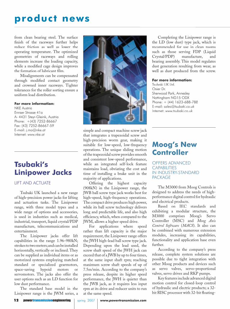
Tsubaki’s Linipower JacksLIFT AND ACTUATE
Tsubaki UK launched a new range of high-precision power jacks for lifting and actuation tasks. The Linipower range, with three model types and a wide range of options and accessories, is used in industries such as medical, industrial, transport, liquid crystal/PDP manufacture, telecommunications and entertainment.
The Linipower jacks offer lift capabilities in the range 1.96–980kN; strokes to two meters; and can be installed horizontally, vertically or inclined. They can be supplied as individual items or as motorized systems employing matched standard or specialized gearmotors, space-saving hypoid motors or servomotors. The jacks also offer the user options such as an LD function for low dust performance.
The standard base model in the Linipower range is the JWM series, a
Completing the Linipower range is the LD (low dust) type jack, which is recommended for use in clean rooms such as those serving FDP (Liquid Crystal/PDP) manufacture, and bearing assembly. This model regulates dust generation resulting from wear, as well as dust produced from the screw.
For more information:Tsubaki UK Ltd.Osier Dr.Sherwood Park, AnnesleyNottingham NG15 ODXPhone: + (44) 1623-688-788E-mail: [email protected]: www.tsubaki.co.uk
Moog’s New Controller OFFERS ADVANCED CAPABILITIES IN INDUSTRY-STANDARD PACKAGE
The M3000 from Moog Controls is designed to address the needs of high-performance digital control for hydraulic and electrical products.
Based on IEC standards and exhibiting a modular structure, the M3000 comprises Moog’s Servo Controller (MSC) and Moog Axis Control Software (Control Software (Control Software MACS). It also can be combined with numerous extension modules, increasing its capabilities, functionality and application base even further.
According to the company’s press release, complete system solutions are possible due to tight integration with other Moog products and devices such as servo valves, servo-proportional valves, servo drives and RKP pumps.
Key features include advanced digital motion control for closed-loop control of hydraulic and electric products; a 32-bit RISC processor with 32-bit fl oating-
from clean bearing steel. The surface fi nish of the raceways further helps reduce friction as well as lower the operating temperature. The optimized geometries of raceways and rolling elements increase the loading capacity, while a modifi ed cage design improves the formation of lubricant fi lm.
Misalignments can be compensated through modifi ed contact geometry and crowned inner raceways. Tighter tolerances for the roller sorting ensure a uniform load distribution.
For more information:NKE AustriaEnnser Strasse 41a A- 4431 Steyr-Gleink, Austria Phone: +(43) 7252-86667 Fax: (43) 7252-86667-59E-mail: [email protected]: www.nke.at
simple and compact machine screw jack that integrates a trapezoidal screw and high-precision worm gear, making it suitable for low-speed, low-frequency operations. The unique sliding motion of the trapezoidal screw provides smooth and consistent low-speed performance, while an integrated self-lock feature maintains load, obviating the cost and time of installing a brake unit in the majority of applications.
Offering the highest capacity (908kN) in the Linipower range, the JWB ball screw type jack works best for high-speed, high-frequency operations. The compact drive produces high power, while its ball screw technology delivers long and predictable life, and also high effi ciency, which, when compared to the JWM, allows a higher speed drive.
For applications where speed rather than lift capacity is the major requirement, the Linipower range offers the JWH high-lead ball screw type jack. Depending upon the lead used, the screw shaft speed of the JWH jack can exceed that of a JWB by up to four times, at the same input shaft rpm; reaching maximum screw shaft speeds of up of 7.5m/min. According to the company’s press release, despite its higher speed performance, the JWH is quieter than the JWB jack, as it requires less input rpm at its drive and reducer units to run at the same speed.

www.powertransmission.com spring 2007 powertransmissionengineering 13
product news
GROUND GEAR SPECIALISTS
Ground Gear Quality
At Shaved Quality t Shaved Quality
At Shaved AGear Prices
New Gleason® 245 TWG GearGrinder offers fast, accurate and economical solutions.
Complementing Niagara‘s full range of CNC and electronic gear grinders is the Gleason 245 TWG, High Speed Threaded Wheel Grinder. This latest technology in high speed production grinding will meet your most demanding needs on PRICE,on QUALITY and on TIME.• Eliminate process related deviations
and heat treat distortion• Maintain critical size consistently• Eliminate undesirable excitations via
direct drives • Affordable hard finishing using
unthinkable metal removal rates• Optimize contact and load carrying
characteristics via algorithmic software
Contact Niagara Gear and put our world class, precision gear grinding
team to work for you today.
1-800-447-2392Fax: 716-874-9003
e-mail: [email protected]
941 Military Rd, Buffalo, NY 14217
point math for powerful, fast and accurate control; and multiple software-confi gurable interfaces to allow for SSI, encoder, CANopen, RS232, Ethernet, Profi bus and analog/digital outputs.
The MSC is a freely programmable, high-performance servo controller, with built-in PLC functionality, capable of handling complex multi-axis functions and enabling cycle times as fast as 500 microseconds. The software element, MACS, is an IEC61131-3-compliant programming language based on the CoDeSys universal standard. It provides full programming, debugging, simulation, parameterization,visualization and trac-ing capabilities.
Extensive function blocks enable easy implementation of closed-loop applications, and various analogue (QAIO) and digital (QDIO) modules are offered for the extension of the local I/O.
For more information contact:Moog Inc. Corporate Headquarters Jamison and Seneca Rd.East Aurora, NY 14052 Phone : (716) 652 -2000 Fax : (716) 687- 4457E-Mail: [email protected]: www.moogcontrols.com/industrial
Belden’s Universal JointEXCEEDS MILITARY STANDARDS
Belden’s complete line of universal joints and shaft assemblies includes a full range of military-certifi ed universal joints used in auto racing/gear change linkage, military personnel carriers and aerospace applications.
Universal joints are designed and manufactured for a variety of applications, including high lift actuation and control mechanisms for
aircraft, where low defl ection rates, high strength-to-weight ratios and long service life are essential.
The heavy-duty MS 271 military standard universal joints have undergone qualifi cation and acceptance testing by a testing lab and the U.S. Department of Defense. The MS joints meet or exceed the requirements of military specifi cation MIL-J-6193.
To qualify the universal joints, a variety of extensive and rigorous testing was completed. Reaction frames were designed and fabricated to perform torsional play, tightness, static torque, endurance and lubrication retention tests.
The Belden MS series of universal joints is the design that is mandated for all government/military and aerospace applications and is also utilized in performance and NASCAR racing. The military standard joint’s high-strength pin-and-block design can be modifi ed into various materials such as aircraft 17-5 and 15-5, and marine grade 316 and 316L stainless steel.
For more information:Belden Inc.2500 Braga Dr.Broadview, IL 60155Phone: (708) 344-4600E-Mail: [email protected]: www.beldenuniversal.com
product news
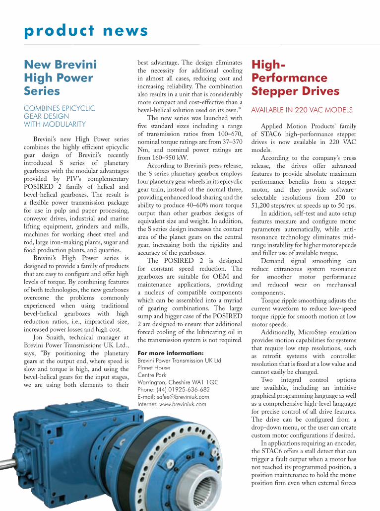
Brevini’s new High Power series combines the highly effi cient epicyclic gear design of Brevini’s recently introduced S series of planetary gearboxes with the modular advantages provided by PIV’s complementary POSIRED 2 family of helical and bevel-helical gearboxes. The result is a fl exible power transmission package for use in pulp and paper processing, conveyor drives, industrial and marine lifting equipment, grinders and mills, machines for working sheet steel and rod, large iron-making plants, sugar and food production plants, and quarries.
Brevini’s High Power series is designed to provide a family of products that are easy to confi gure and offer high levels of torque. By combining features of both technologies, the new gearboxes overcome the problems commonly experienced when using traditional bevel-helical gearboxes with high reduction ratios, i.e., impractical size, increased power losses and high cost.
Jon Snaith, technical manager at Brevini Power Transmissions UK Ltd., says, “By positioning the planetary gears at the output end, where speed is slow and torque is high, and using the bevel-helical gears for the input stages, we are using both elements to their
New Brevini High Power SeriesCOMBINES EPICYCLIC GEAR DESIGN WITH MODULARITY
best advantage. The design eliminates the necessity for additional cooling in almost all cases, reducing cost and increasing reliability. The combination also results in a unit that is considerably more compact and cost-effective than a bevel-helical solution used on its own.”
The new series was launched with fi ve standard sizes including a range of transmission ratios from 100–670, nominal torque ratings are from 37–370 Nm, and nominal power ratings are from 160–950 kW.
According to Brevini’s press release, the S series planetary gearbox employs four planetary gear wheels in its epicyclic gear train, instead of the normal three, providing enhanced load sharing and the ability to produce 40–60% more torque output than other gearbox designs of equivalent size and weight. In addition, the S series design increases the contact area of the planet gears on the central gear, increasing both the rigidity and accuracy of the gearboxes.
The POSIRED 2 is designed for constant speed reduction. The gearboxes are suitable for OEM and maintenance applications, providing a nucleus of compatible components which can be assembled into a myriad of gearing combinations. The large sump and bigger case of the POSIRED 2 are designed to ensure that additional forced cooling of the lubricating oil in the transmission system is not required.
For more information:Brevini Power Transmission UK Ltd.Planet HouseCentre ParkWarrington, Cheshire WA1 1QCPhone: (44) 01925-636-682E-mail: [email protected]: www.breviniuk.com
High-Performance Stepper Drives AVAILABLE IN 220 VAC MODELS
Applied Motion Products’ family of STAC6 high-performance stepper drives is now available in 220 VAC models.
According to the company’s press release, the drives offer advanced features to provide absolute maximum performance benefi ts from a stepper motor, and they provide software-selectable resolutions from 200 to 51,200 steps/rev. at speeds up to 50 rps.
In addition, self-test and auto setup features measure and confi gure motor parameters automatically, while anti-resonance technology eliminates mid-range instability for higher motor speeds and fuller use of available torque.
Demand signal smoothing can reduce extraneous system resonance for smoother motor performance and reduced wear on mechanical components.
Torque ripple smoothing adjusts the current waveform to reduce low-speed torque ripple for smooth motion at low motor speeds.
Additionally, MicroStep emulation provides motion capabilities for systems that require low step resolutions, such as retrofi t systems with controller resolution that is fi xed at a low value and cannot easily be changed.
Two integral control options are available, including an intuitive graphical programming language as well as a comprehensive high-level language for precise control of all drive features. The drive can be confi gured from a drop-down menu, or the user can create custom motor confi gurations if desired.
In applications requiring an encoder, the STAC6 offers a stall detect that can trigger a fault output when a motor has not reached its programmed position, a position maintenance to hold the motor position fi rm even when external forces

www.powertransmission.com spring 2007 powertransmissionengineering 15
product news
Immediate Opportunities inChallenging Aerospace Careers.
Apache by Boeing,
transmissionsby Purdy.
TEAMAPACHEProud Supporters ofAmerica’s Military.
INNOVATIVE, DYNAMIC,CREATIVE,CHALLENGING.JOIN US!
The Purdy Corporation is a leader in manufacturing flight critical Jet engine and rotor components including
gears, gear boxes and transmissions for OEMs and the United States Government.
Aerospace manufacturing opportunities offering stability, job satisfaction and growth are available
in the following areas of expertise;
• Gear Management - Aerospace Manufacturing
• CNC Programming (Unigraphics) -
Gear Box Housings, High Speed Machining,
• Gear Engineering - Process, Planning & Manufacturing
• Gear Machining - Spiral Bevel and Parallel Axis • ID/OD Grinding
• Gear Metrology • Gear Box Assembly and Testing
Excellent benefit and relocation packages.An Equal Opportunity/Affirmative Action Employer.An Equal Opportunity/Affirmative Action Employer.
Take your career to a whole new level, contact us at860.649.0000 Ext. 226 or e-Mail to [email protected]
Sharq Motion’s New Parallel Shaft GearmotorsOFFER BACKWARDS COMPATIBILITY
The new Sharq 207 series parallel-shaft gearmotors, designed as direct drop-in replacements for many high-volume OEM applications, are the fi rst in a family of eleven new gearmotor designs being introduced in 2007.
Powered by 1/20 horsepower AC motors, the four standard models in the Sharq 207 series offer torque ratings from 42 to 113 in-lbs, with 2 to 29 rpm output speeds at full load current of 1.3 amps. Rated at 115 volt, 60 hertz, the Sharq 207 series employs shaded pole electric motors, with clockwise rotation as standard.
are trying to move it out of position, and stall prevention where the drive will work to end the desired move with new parameters.
For more information:Applied Motion Products Co.404 Westridge Dr.Watsonville, CA 95076Phone: (800) 525-1609, (831) 761-6555E-mail: [email protected]: www.applied-motion.com
According to the company’s press release, the totally enclosed, fan-cooled (TEFC) design offers high output in a compact 4.94"diameter, 7.47" length package.
With a 0.625" diameter output shaft and 150 lb. overhung load rating, the gearmotors feature an integral foot plate mount, as well as a three-point
face mount, for easy mounting in any position.
For more information:Sharq MotionPhone: 888-SHARQ07E-mail: [email protected]: www.sharqmotion.com

Single-vendor sourcing has probably never been more attractive to businesses of all types—especially manufacturing—than it is today. The concept makes perfect sense, especially for companies that buy power transmission and motion control components. Big dollars and perhaps even bigger safety issues ride on the quality, performance and reliability of the components used for any number of applications.
But fi nding that one supplier—or strategic partner—can be a frustrating, costly, time-consuming quest. And that is exactly where the Chicago-based Power Transmission Distributors Association (PTDA) can help in a meaningful way. With its more than 400 distributor and manufacturer members, the association provides and coordinates valuable networking and information-gathering opportunities for its membership, whether they be established companies or start-up entrepreneurs trying to learn the industry ins and outs. And given the robust industry fi gures, the importance of those opportunities can’t be minimized. Figures released for 2005 show that the North American market for power transmission (PT) and motion control (MC) products was estimated at $84.2 billion, which includes more than $50 billion for MRO (maintenance, repair and operations) use and $34 billion in purchases by OEMs. Typically, according to the PTDA, distributors cater to the MRO and smaller OEM markets, and manufacturers focus on large-volume OEMs.
Education through participation. PTDA president (and owner of Saginaw, MI-based Northern Industrial Supply, Inc.) Jeff Pickleman was once one of those with a lack of industry knowledge but looking to learn. For him, the association was the answer.
“When I fi rst started in this business 21 years ago, I had
interview interview
16 powertransmissionengineering spring 2007 www.powertransmission.com spring 2007 transmission
PTDABoosts Power Transmission and Motion Control Industries
Jack McGuinn, Senior Editor
almost no knowledge of the industry, and had no clue what a gear box or a bearing was,” he says. “I had very few contacts and found myself among a sea of competitors, many of whom had lifelong careers in industrial distribution. Becoming active in PTDA allowed me the opportunity to learn the industry, build a network of new business partners and professionals, and discover unique ways of doing business. I met other members who showed me the ropes—people I still call on today for support and encouragement.” Pickelman adds that in order to best gain all that the PTDA offers, “The fi rst step is to participate.”
But before moving on in greater detail, it is perhaps useful to also understand what the association is, and is not. Ann Arnott, the PTDA’s director of programs and services, explains the distinction.
“The PTDA is a non-profi t, 501 (c) (6) trade association. Our goal is to bring people of like minds together for the purposes of networking, education—all the things that you can get by talking to your colleagues in the industry. We’re not a buying consortium; we don’t do any transactions, we don’t coordinate between our members about who’s going to distribute whose products. That’s totally at our members’ discretion.
“Our goal is to increase awareness of the power transmission and motion control industries, as well as to bring the membership together to do good things for the industry as a whole.” In other words, says Arnott, “We bring them together and they make their own matches.”
Other goals stated on their website include: winning members’ trust as a strategic business partner; aiding in the qualifi cation, training and competency of members’ personnel; providing the go-to forum for establishing and maintaining relationships, business opportunities and profi t enhancement; and to also promote unions with related supplier, distributor and customer associations that will serve PT and MC interests.
Qualifi cations for membership are straightforward, and align with the PTDA’s hands-off stance regarding its policy of never getting involved with manufacturer/distributor matchmaking. Membership dues are a fl at fee based upon a sliding scale percentage of a company’s annual sales.
“Any manufacturer or distributor is welcome to apply for membership,” says Arnott. “If (a company) distributes motion control and power transmission products, or manufactures products, they can be a member.”
Networking a key attraction. The PTDA does not concern itself with determining whether members are, for example, ISO- or QS-certifi ed. That is an issue for each would-be suitor to address. What it does concern itself with is networking, underscoring the adage that, to a great degree, success is often facilitated by simply showing up.
“Our members tell us that—without fail—it is their ability to network with people who have solutions to problems that they have,” says Arnott. “A company can contact any
Jeffrey Pickleman

interview interview
transmission spring 2007 www.powertransmission.com spring 2007 powertransmissionengineering 17
common malady facing manufacturing nationwide—securing the industry’s future. As with other sectors, the issues are aging workforce and awareness.
“Everybody’s getting a little bit older,” as Arnott puts it gently, “and the industrial distribution fi eld is one of the hidden industries; no one knows it exists. Everybody knows that things get made, but nobody knows how that stuff got there. It’s not something that a whole lot of people talk about, yet I saw a statistic the other day that four trillion dollars worth of business is done through distribution. The ICP goal is to, one—increase awareness of industrial distribution, and two—to get kids thinking about it as a viable, fi nancially rewarding and satisfying career.”
Learning institutions are also among PTDA’s membership. Member schools and the PTDA nurture a symbiotic relationship in that some schools serve as sites for the ICP program, while others offer certifi cate programs or associate degrees in industrial distribution that combine business and technology curricula. And, adds Arnott, the schools seek membership for a very practical and useful reason for faculty and students alike.
“They are members of the association just so they can keep up with what’s going on in their students’ world.”
For more information:Power Transmission Distributors Association (PTDA) 230 West Monroe / Ste. 1410Chicago, IL 60606-4703Phone: (312) 516-2100Fax: (312) 516-2101E-mail: [email protected]: www.ptda.org
When I fi rst started in this business 21 years ago, I had almost no knowledge of the industry, and had no clue what a gear box or a bearing was. I had very few contacts and found myself among a sea of competitors, many of whom had lifelong careers in industrial distribution. Becoming active in PTDA allowed me the opportunity to learn the industry, build a network of new business partners and professionals, and discover unique ways of doing business.—Jeffrey Pickleman, PTDA president
of the other PTDA member companies throughout (North America) that have been in the same situation and learn from their experience—how did it work for them, what do they wish they had known. Without a doubt, they say it’s the networking.”
Speaking of networking, the association’s largest event of the year is their Annual Summit, to be held this October at the Marriott Desert Springs Resort in Palm Desert, CA. Not really a trade show, but rather a well-attended symposium affording members face-to-face opportunities to meet-and-greet and learn of the newest industry trends, developments and innovations. In fact, the theme of this year’s event is “Communicate. Collaborate. Innovate.”
A major part of the summit is MD-IDEX—or the manufacturing, distribution, and ideas exchange. The event is so valuable to PTDA members that Arnott says some claim it is their primary reason for joining. Arnott stresses that members recognize the PTDA’s role in promoting members’ value-added services and expertise for their customers.
Choices—and choice opportunities. Of equal importance, the PTDA also offers choices—for buyer and seller alike. To illustrate that point, Arnott uses the neighborhood supermarket as an example of a source for a wide array of products. If, say, you want a Pepsi or Coke, you don’t go to PepsiCo or Coca-Cola for it—you go to the nearest store that stocks it. Or, importantly, perhaps dozens of other brands.
Similarly, as Arnott points out, “That’s like what our distributors bring you; not only do they offer extensive selections from having different manufacturers, they also can offer you the training, skills and innovation of knowing how to make your product work better using the products of different manufacturers.”
The PTDA is also involved in a number of educational products and endeavors, but its most popular learning tool is actually a resource—the PTDA Power Transmission Handbook, available for $39.95 ($49.95 for non-members). Produced by the PTDA’s technical committee, the 17-chapter publication is in fact a “training manual for power transmission/motion control products, technologies and concepts.” Each chapter is dedicated to a particular industry-related product type or technology, along with information on how and where it is typically used, and specifi c maintenance and diagnostic recommendations. The manual is peppered with visual learning aids—charts, diagrams, drawings and photos—to enhance the learning experience. Essentially a primer for newcomers to the industry, the manual is designed for both entry-level employees and unschooled entrepreneurs much like Pickelman and his description of his fi rst years in the business. The book addresses everything from power transmission fundamentals, bearings, belts and drives, to lubrication, adjustable-speed motors and vibration analysis.
Looking to get younger. The association also maintains an educational foundation. Its current big-picture project is Industrial Careers Pathway (ICP), intended to confront the

The SKF High-Capacity Cylindrical Roller Bearing
The SKF High-Capacity Cylindrical Roller Bearing
18 powertransmissionengineering spring 2007 www.powertransmission.com
IntroductionTh e ISO defi nition of a full-comple-
ment bearing states that the bearing does not have a cage. When that defi nition was written, it was not technically pos-sible to have a full-complement bearing with a cage. But SKF’s new high-capac-ity cylindrical roller bearing combines the load-carrying capacity of a full-complement bearing with the benefi ts of a bearing with a cage (Fig.1).
HistoryIn 1960, when SKF introduced the
E-design cylindrical roller bearing, it
Jürgen Reichert and Jochen Baum
was seen as an important step in the development of standard cylindrical roller bearings. Th e bearing was based on standardized boundary dimensions; it was the internal macro geometry that made it diff erent from other bearings. SKF engineers had found a way to op-timize the number of rollers, the roller size and the thickness of the inner and outer rings, leading to an increased load-carrying capacity and rated bearing life.
In the 1980s, SKF engineers went on to develop the EC design, which had a higher thrust load-carrying capacity,

continued
www.powertransmission.com spring 2007 powertransmissionengineering 19
and then the SKF Explorer cylindrical roller bearings, which were launched in 2002. Th e SKF Explorer bearings ben-efi ted from improved material and an improved heat-treatment process, but it was mainly the improved micro geom-etry that gave these bearings a competi-tive advantage. Using knowledge gained over the years, together with proprietary software, engineers were able to maxi-mize the eff ects of the lubricant fi lm build-up and decrease the friction with-in the bearing.
Load-Carrying CapacityLoad-carrying capacity is calculated
using formulas in the standards ISO 76 and ISO 281. According to these for-mulas, there are two ways to increase the load-carrying capacity of a bearing while maintaining standardized bound-ary dimensions:
• Increase the dimensions of the rollers and maintain the same number of rollers; or
• Increase the number of rollers and maintain the roller dimensions.
From a practical point of view, the fi rst method leads to a technical prob-lem. Increasing the size of the rollers will reduce the thickness of the inner and outer rings and the width of the side fl anges. Th is has no eff ect on the theoretical load-carrying capacity calcu-lation. In reality, however, these changes will reduce ring stiff ness and fl ange strength. For the end user, this means a higher risk of micro movements in the bearing seating, which causes fretting corrosion or ring creep. Larger rollers also increase the risk of smearing dam-age, due to their higher moment of in-ertia.
All in all, the fi rst method, though impressive on paper, cannot be con-sidered an improvement. Th e second alternative, however, does off er viable alternatives. Based on the former im-provements of the macro and micro geometries, the roller dimensions and wall thickness of the bearing rings can remain unchanged, compared with the dimensions of the proven 45-year-old E-design.
However, increasing the number of rollers within a defi ned envelope is not
Figure 1—A standard cyclindrical roller bearing uses a brass cage located at the rollers’ pitch diameter (1). SKF engineers have developed inner-ring (2) and outer-ring (3) shoulder-guided cages, allowing them to add rollers without increasing the overall dimensions of the bearing.
as easy as it sounds. To make this new bearing a reality, SKF engineers and sci-entists needed to work through a num-ber of key issues.
“Add More Rollers”—Easy to Say, Hard To Do
Th ere are two types of rolling ele-ment bearings: caged bearings and full-complement bearings. Full-complement bearings, which do not use a cage, are fi tted with a maximum number of roll-ers. In this type of bearing, the rollers are in direct contact with each other, which causes sliding and increases friction and heat generation. Under certain circum-stances, this leads to wear and prema-ture bearing failure, making them unac-ceptable for applications where there are higher speeds. Th is makes a cage essen-tial for higher-speed applications.
Medium- and large-size cylindrical roller bearings are equipped as standard with a machined brass cage, mainly to keep the rollers from making contact. Th e cage bars, which usually are orien-tated around the roller pitch circle (the connecting circle of the mid-points of all rollers), have a defi ned cross section designed for maximum strength, but they reduce the number of rollers theo-retically possible. However, by moving the cage bars away from the roller pitch
circle, the rollers can be placed closer to each other so that more rollers can be incorporated into the bearing (Fig. 1). To do this, SKF developed a new win-dow-type steel cage.
Th is resulted in two basic cage de-signs—a JA-style, outer-ring shoulder-guided cage (Fig. 2) and a JB-style, in-ner-ring shoulder-guided cage (Fig. 3).
More than Cage BarsLarger window-type steel cages are
not new. Cage diameters up to 1,300 mm have been used in large-size, ta-pered roller bearings for years, with excellent results. Th e development was based on the same material thickness as a comparable tapered roller bearing cage, using a shoulder guidance of the cage to provide better performance for occur-ring radial accelerations and shocks. But the development team was faced with a number of issues. First and probably most important was how to maximize cage strength while enhancing the for-mation of a lubricant fi lm. Th e team also needed to fi nd a way to minimize stress concentrations in the transition between the cage bars and side rings.
Using proprietary SKF software and knowledge gained from years of experi-ence, the team determined that it could minimize stress concentrations in criti-
continued

20 powertransmissionengineering spring 2007 www.powertransmission.com
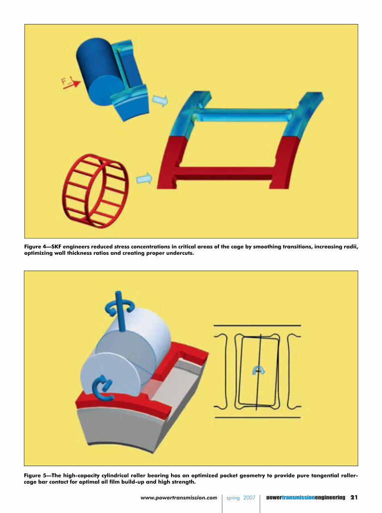
cal areas by smoothing transitions, in-creasing radii, optimizing wall thickness ratios and creating proper undercuts (Fig. 4). Th e team then went a step fur-ther to provide pure tangential contacts between the rollers and cage bars. Th e contact angles were optimized, and the cage bar was designed with a slightly waisted shape (Fig. 5). Th is reduces con-tact pressures and enhances lubricant fi lm build-up, but it also avoids edge contacts and thus localized dry running because of the scraping off of the lubri-cant. Th ese design features have been proven theoretically as well as in prac-tice, and a patent application has been fi led.
In combination with steel as a cage material and shoulder support, the new features lead to strength that is compa-rable to standard brass cage executions. Even more remarkable, this is in spite of an increased number of rollers.
applied speed corresponds to the limit-ing speed of the catalog bearing.
Th e tests were conducted under two diff erent lubrication conditions. In one case, oil with a proper viscosity to pro-vide a suffi cient oil fi lm (κ > 1.5) was used. In the other case, a low-viscosity oil to simulate an inadequate lubrication condition (κ < 0.5) was used. When all the tests were completed, a 1,000-hour duration test was conducted. During the tests, all critical performance parameters such as temperatures, loads, speed and vibration levels were monitored con-tinuously. (Editor’s note: Th e eff ectiveness of a lubricant is primarily determined by the degree of separation between the rolling contact surfaces. If an adequate lubricant fi lm is to be formed, the lubricant must have a given minimum viscosity when the ap-plication has reached its normal operating temperature. Th e condition of the lubricant is described by the viscosity ratio κ as the ratio of the actual viscosity ν to the rated viscosity ν1 for adequate lubrication, both values being considered when the lubricant is at normal operating temperature.)
Speed and Functional ResultsBased on the results of the measure-
ments, together with an in-depth exam-ination of the various bearing compo-nents after the test, no restrictions could be found to the SKF high-capacity cylindrical roller bearing usage limits, compared with the standard bearing.
When compared with a machined brass cage, the reduced cage cross sec-tion of the high-capacity cage improves oil fl ow through the bearing to maxi-mize the eff ects of the lubricant and reduce heat generated by the bearing. Another advantage of the high-capac-ity cage is that its lower weight reduces inertial forces. Th is can be particularly important in applications where there are frequent fast starts and stops and in applications subjected to radial accelera-tions, such as planet wheels.
Low-Load Tests & ResultsIn addition to high-speed and cage
stability tests, the bearings were also tested under minimum load condi-tions to investigate the risk of roller slip, smearing and other damage that typi-
Figure 2—An SKF high-capacity roller bearing with the JA-style outer-ring shoul-der-guided cage.
Figure 3—An SKF high-capacity roller bearing with the JB-style inner-ring shoul-der-guided cage.
In addition to the development of the new cage design, high-capacity cy-lindrical roller bearings have, by default, black oxidized rollers and bearing rings to improve the run-in behavior of the bearing. Th is surface treatment gives the bearing its dark color.
Once theoretical calculations and simulations were completed, the new cage design was tested for more than a year. During this time, more than 20 val-idation tests were conducted. Th e tests, which used 2334 size cylindrical roller bearings, were designed to compare the performance of both high-capacity cage variants with a standard shoulder-guid-ed, machined brass cage.
Speed and Functional TestsTo assess speed capability and cage
stability, n x dm values (rotational speed x bearing mean diameter) of up to 800,000 mm/min were applied under alternating radial and axial loads. Th e
continued
www.powertransmission.com spring 2007 powertransmissionengineering 21
Figure 5—The high-capacity cylindrical roller bearing has an optimized pocket geometry to provide pure tangential roller-cage bar contact for optimal oil film build-up and high strength.
Figure 4—SKF engineers reduced stress concentrations in critical areas of the cage by smoothing transitions, increasing radii, optimizing wall thickness ratios and creating proper undercuts.
22 powertransmissionengineering spring 2007 www.powertransmission.com spring 2007 transmission
and condition monitoring industries. From a bearing standpoint, high-capac-ity cylindrical roller bearings have found their application here. Th ey are mainly developed for cylindrical roller bearings in the 22 and 23 heavy series, from me-dium to large sizes (bore diameter from 150 mm up to approximately 300 mm). Other sizes can be manufactured on re-quest. Depending on the cage variant, bearings in the 23 series can have up to two extra rollers; bearings in the 22 se-ries can have up to three or more rollers, when compared with a standard bearing of the same size. It is notable that the JA cage variant for bearings in the 23 series has as many rollers as the full-comple-ment version, so it has reached the up-per limit of load-carrying capacity. In this case, one can indeed speak of a full-complement bearing with a cage.
For a wind turbine, this increased load-carrying capacity provides an op-portunity to downsize or increase power density. Either way, it is an important development for an application that is perched atop a pedestal 90 meters in the air.
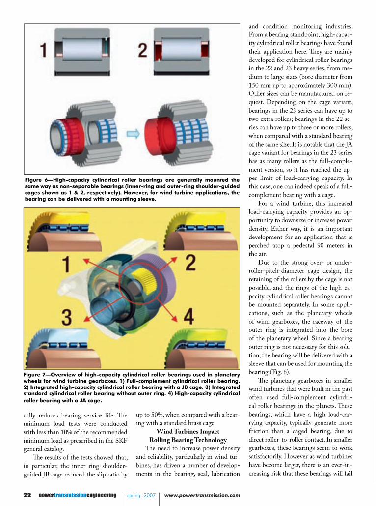
Due to the strong over- or under-roller-pitch-diameter cage design, the retaining of the rollers by the cage is not possible, and the rings of the high-ca-pacity cylindrical roller bearings cannot be mounted separately. In some appli-cations, such as the planetary wheels of wind gearboxes, the raceway of the outer ring is integrated into the bore of the planetary wheel. Since a bearing outer ring is not necessary for this solu-tion, the bearing will be delivered with a sleeve that can be used for mounting the bearing (Fig. 6).
Th e planetary gearboxes in smaller wind turbines that were built in the past often used full-complement cylindri-cal roller bearings in the planets. Th ese bearings, which have a high load-car-rying capacity, typically generate more friction than a caged bearing, due to direct roller-to-roller contact. In smaller gearboxes, these bearings seem to work satisfactorily. However as wind turbines have become larger, there is an ever-in-creasing risk that these bearings will fail
Figure 6—High-capacity cylindrical roller bearings are generally mounted the same way as non-separable bearings (inner-ring and outer-ring shoulder-guided cages shown as 1 & 2, respectively). However, for wind turbine applications, the bearing can be delivered with a mounting sleeve.
Figure 7—Overview of high-capacity cylindrical roller bearings used in planetary wheels for wind turbine gearboxes. 1) Full-complement cylindrical roller bearing. 2) Integrated high-capacity cylindrical roller bearing with a JB cage. 3) Integrated standard cylindrical roller bearing without outer ring. 4) High-capacity cylindrical roller bearing with a JA cage.
up to 50%, when compared with a bear-ing with a standard brass cage.
Wind Turbines Impact Rolling Bearing Technology
Th e need to increase power density and reliability, particularly in wind tur-bines, has driven a number of develop-ments in the bearing, seal, lubrication
Jürgen Reichert is a product manager at SKF Development Centre in Steyr, Austria. Jochen Baum is a product development engineer at SKF GmbH in Schweinfurt, Germany.
cally reduces bearing service life. Th e minimum load tests were conducted with less than 10% of the recommended minimum load as prescribed in the SKF general catalog.
Th e results of the tests showed that, in particular, the inner ring shoulder-guided JB cage reduced the slip ratio by

transmission spring 2007 www.powertransmission.com spring 2007 powertransmissionengineering 23
Figure 8—High-capacity cylindrical roller bearings used in helical wind turbine gearboxes. 1) Intermediate shaft with NCF 2336 ECJB. 2) Output shaft with NCF 2234 ECJB.
prematurely, due to smearing and wear. Comparison of Diff erent
Bearing DesignsIn Figure 7, various bearing de-
signs are compared, using a wind tur-bine gearbox as an example. Standard cylindrical roller bearings with a brass cage have a lower calculated life than full-complement roller bearings in the planetary drive unit. If you compare a full-complement bearing to SKF’s new high-capacity cylindrical roller bearing, the gap narrows. And when the high-capacity bearing is manufactured to the SKF Explorer performance class, the rated life of the bearing exceeds the life of a full-complement bearing.
Th is is not a unique example. Simi-lar results can be seen in the intermedi-ate and output shafts of a spur or he-lical gear transmission. In this type of transmission, a full-complement bear-ing cannot be used, due to the higher speeds. In addition, the bearing typically does not have the required minimum load applied to it. As a result, when comparing the calculated bearing life of the standard caged bearing with the life of a similarly sized high-capacity bear-ing (Fig. 8), there is the possibility of in-creasing bearing life by up to 35%. Th e inner-ring guided cage variant is recom-mended in this application because of its resistance to smearing.
For more information:Albert Krauss, product managerSKF GmbHPostfachDE-97419 SchweinfurtGermanyPhone: +(49) 9721-562461Fax: +(49) 9721-5662461Email: [email protected]: www.skf.com
Bearing Execution
Standard SKF Explorer*
Customized bearing for wind turbine
gearbox appli-cation
Full-complement cylindrical
roller bearing
High-capacity cylin-drical roller bearing with an outer-ring guided cage
(JA)
High-capacity cylin-drical roller bearing with an inner-ring guided cage
(JB)
Integrated standard cylin-
drical roller bearing with a machined brass cage
Number of rollers per row
29 28 26 24
Relative calculated bearing life (ISO) (%)
100 135 109 92
*SKF Explorer bearings with increased load-carrying capacity.
Bearing variant
Standard N 2336 ECMB*
High-capacity
NCF 2336 ECJB
Standard N 2234 ECMB
*
High-capacity
NCF 2234 ECJB
Number of rollers
13 14 16 18
Relative calculated bearing life (ISO) (%)
100 119 100 135
*Not displayed here.
Jürgen Reichert is a product manager at SKF Development Centre in Steyr, Austria. Jochen Baum is a product development engineer at SKF GmbH in Schweinfurt, Germany.
Th is article fi rst appeared in Evolution—SKF’s business and tech-nology magazine. It is reprinted here with permission. You can see the original version online at http://evolution.skf.com.

P.O Box 80 · 11715 Main Street · Roscoe, IL 61073-0080 815-623-2168 · Fax: 815-623-6620 · www.forestcitygear.com
Presenting ...As Forest City Gear heads into 2007, we have some new additions - not only in our family, but in gear equipment and personnel.
New in 2007:A Bourn & Koch/Fellows 450mm CNC Shaper with crowning via servo control and guideless helical special accuracy keeps us in a class of our own.
A Koepfer 200 with high helix capability for worms and gears fully automated takes our productivity to a higher level.
For FCG inspections, we announce our new Wenzel analytical gear checker 600mm with a meter long center support and large bore table to swallow extra long shafts.
Our secondary support team acquires a SUNNEN SV 1005 vertical, automated hone.
In personnel, new staff members Appy Young Mikel and Rustin Mikel have presented Joseph Arnold Mikel as our next generation leader in the making. Watch out Gear World!
•
•
•
•
•
Fred Young holding his grandson Joseph Arnold Mikel.
the next generationof world class gear makers.
Forest City Gear...the most modern fine and medium pitch gear
shop in the world.

26 powertransmissionengineering spring 2007 www.powertransmission.com
IntroductionTh e total U.S. electric motor base
exceeds 100 million motors and con-sumes more than 50% of all electricity generated in the country. Small mo-tors—fractional horsepower to 20-hp—comprise 99% of the motor population but consume only 25% of all generated electricity (Refs. 1,3,10,14). Large mo-tors—only 1% of the general motor population—consume 25% of all elec-tricity generated in the United States and are primarily located in industrial applications.
Th is article considers the economics and reliability of replacing older indus-trial motors. Th e data collected from 100 motors and case studies indicate that the economics of replacing mo-tors operating at less than 60% of rated load—more than 40% of the motors studied—are not adequately represented by the MotorMaster+ software tool.
Part II: Industrial Motor Decision Support Tools, coming next issue, will look at the impact the 100-motor study has made on various tools that facilitate
cycle costs of the motor, particularly in terms of payback on the incremental cost of a higher-effi ciency motor. Be-cause they are prime consumers of elec-tricity, the effi ciency of these motors has signifi cant impact on their replacement economics.
Calculating the replacement eco-nomics includes several factors specifi c to the company, facility, and applica-tion—payback period/return-on-invest-ment (ROI) criterion, average electric rate ($/kWh), operating hours and load. Th e simplest payback calculation is
(1)
where• T is the simple payback period in
years,• Xreplace is the purchase price of the new
motor, including any discounts,• Xrepair is the cost to repair the old mo-
tor,• hp is the horsepower rating of the motor,• SF is the motor operating load, ex-
Results from a 100-Motor Study: Part I of IIINicole M. Kaufman, Advanced Energy
�
−
newold
repairreplace
UCSFhp
XXT
��������
�����
Replacing Motors,Counting Savings
industrial motor management, particu-larly the repair vs. replace decision.
Part III: Decision Support Tools for Small Motors, coming in two issues, will discuss considerations in determining the economics of motor purchases from the viewpoint of an original equipment manufacturer (OEM). In particular, Part III will discuss how to evaluate warranty risk compared to motor reliability.
BackgroundIndustrial electric motors convert
electrical energy into mechanical work at such a magnitude that their energy costs eclipse their initial purchase cost. You wouldn’t normally compare a mun-dane, 75-hp industrial motor to a Lam-borghini or Ferrari. However, when you include operating costs over 10 years, the motor can cost more than either of these luxury cars (Table 1). Moreover, the initial purchase price of the electric motor accounts for less than 1% of life-cycle costs, while energy costs make up 99% of the life-cycle costs. Th erefore, any increase in operational effi ciency can have signifi cant impact on the life-

continued
www.powertransmission.com spring 2007 powertransmissionengineering 27
pressed as a percent of rated load,• C is the average facility electric cost
($/kWh),• U is the annual operating hours of the
motor, and• η is the rated load effi ciency of the old
and new motor, respectively.If the payback period calculated is
acceptable, the motor should be replaced with a new motor; if the payback period is unacceptable, then the motor should be sent for repair.
Some argue that this model is too simple for application in the complex economy of industry (Refs. 3, 6). When a new motor purchase is planned and specifi cally budgeted, particularly for expansion or upgrade, it makes sense to account for the present value of the energy savings, as these authors argue. Interestingly, their models do not ac-count for the depreciation of the capital cost of the motor, which should also be included in a more complex analysis. However, maintenance budgets rarely include factors for energy savings by upgrade and capital depreciation, so at
the level where these decisions are most commonly made, the simple model pro-vides enough justifi cation for the deci-sion at hand.
Th is simple model of the economics is used in several motor decision tools. Th e Horsepower Bulletin, published by Advanced Energy, rearranges this equa-tion, solving for horsepower, to deter-mine a “horsepower breakpoint”—the horsepower rating at and below which all motors should be replaced at failure, and above which all motors should be repaired. Previous publications of this tool required the user to make several assumptions regarding the factors that infl uence the payback period, including
motor operating load, effi ciency and ac-ceptable payback period; however, this tool was recently reinvented as an online calculator where the user inputs his or her particular factors.
Similarly, MotorMaster+, created and maintained by the Washington State University Energy Program, uses this simple payback equation, and lat-er versions of this software allow the user to select more advanced economic models, including net present value and depreciation, and to enter their rates (Ref. 9).
A sensitivity analysis of Equation 1 shows that the most infl uential factors are electric cost and payback period. It is
Table 1: Comparison of Electric Motor and Luxury Car Lifecycle Costs 75-Hp Motor 1 Ferrari 612 Scaglietti 2 Lamborghini Gallardo 2 Initial cost $ 2,500 $262,600 $195,000 Annual operation 8,000 hours 12,000 miles 12,000 miles Efficiency 94.1% 17 mpg 17 mpg Energy consumed 475,664 kWh 706 gal 706 gal Energy rate $ 0.060 / kWh $ 2.659 / gal $ 2.659 / gal Annual energy cost $ 28,540 $1,877 $1,877 Lifecycle cost $ 287,999 $ 281,369 $ 213,769 Initial as % of life 1% 93% 91% 1 Electric motor data from MotorMaster+ with no discount applied 2 Vehicle data from Edmunds.com
�
Which would you rather purchase, own and operate for 10 years, a Lamborghini Gallardo or a 75 hp industrial motor? See Table 1, below, for a direct lifecycle cost comparison.
$
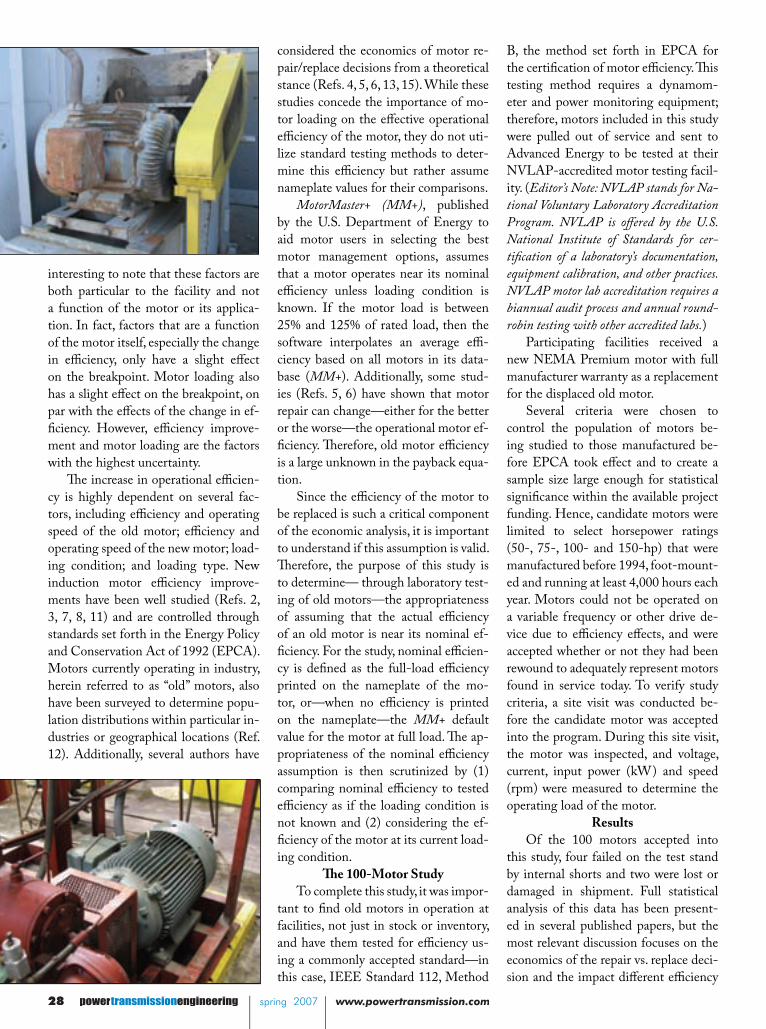
28 powertransmissionengineering spring 2007 www.powertransmission.com
interesting to note that these factors are both particular to the facility and not a function of the motor or its applica-tion. In fact, factors that are a function of the motor itself, especially the change in effi ciency, only have a slight eff ect on the breakpoint. Motor loading also has a slight eff ect on the breakpoint, on par with the eff ects of the change in ef-fi ciency. However, effi ciency improve-ment and motor loading are the factors with the highest uncertainty.
Th e increase in operational effi cien-cy is highly dependent on several fac-tors, including effi ciency and operating speed of the old motor; effi ciency and operating speed of the new motor; load-ing condition; and loading type. New induction motor effi ciency improve-ments have been well studied (Refs. 2, 3, 7, 8, 11) and are controlled through standards set forth in the Energy Policy and Conservation Act of 1992 (EPCA). Motors currently operating in industry, herein referred to as “old” motors, also have been surveyed to determine popu-lation distributions within particular in-dustries or geographical locations (Ref. 12). Additionally, several authors have
considered the economics of motor re-pair/replace decisions from a theoretical stance (Refs. 4, 5, 6, 13, 15). While these studies concede the importance of mo-tor loading on the eff ective operational effi ciency of the motor, they do not uti-lize standard testing methods to deter-mine this effi ciency but rather assume nameplate values for their comparisons.
MotorMaster+ (MM+), published by the U.S. Department of Energy to aid motor users in selecting the best motor management options, assumes that a motor operates near its nominal effi ciency unless loading condition is known. If the motor load is between 25% and 125% of rated load, then the software interpolates an average effi -ciency based on all motors in its data-base (MM+). Additionally, some stud-ies (Refs. 5, 6) have shown that motor repair can change—either for the better or the worse—the operational motor ef-fi ciency. Th erefore, old motor effi ciency is a large unknown in the payback equa-tion.
Since the effi ciency of the motor to be replaced is such a critical component of the economic analysis, it is important to understand if this assumption is valid. Th erefore, the purpose of this study is to determine— through laboratory test-ing of old motors—the appropriateness of assuming that the actual effi ciency of an old motor is near its nominal ef-fi ciency. For the study, nominal effi cien-cy is defi ned as the full-load effi ciency printed on the nameplate of the mo-tor, or—when no effi ciency is printed on the nameplate—the MM+ default value for the motor at full load. Th e ap-propriateness of the nominal effi ciency assumption is then scrutinized by (1) comparing nominal effi ciency to tested effi ciency as if the loading condition is not known and (2) considering the ef-fi ciency of the motor at its current load-ing condition.
Th e 100-Motor StudyTo complete this study, it was impor-
tant to fi nd old motors in operation at facilities, not just in stock or inventory, and have them tested for effi ciency us-ing a commonly accepted standard—in this case, IEEE Standard 112, Method
B, the method set forth in EPCA for the certifi cation of motor effi ciency. Th is testing method requires a dynamom-eter and power monitoring equipment; therefore, motors included in this study were pulled out of service and sent to Advanced Energy to be tested at their NVLAP-accredited motor testing facil-ity. (Editor’s Note: NVLAP stands for Na-tional Voluntary Laboratory Accreditation Program. NVLAP is off ered by the U.S. National Institute of Standards for cer-tifi cation of a laboratory’s documentation, equipment calibration, and other practices. NVLAP motor lab accreditation requires a biannual audit process and annual round-robin testing with other accredited labs.)
Participating facilities received a new NEMA Premium motor with full manufacturer warranty as a replacement for the displaced old motor.
Several criteria were chosen to control the population of motors be-ing studied to those manufactured be-fore EPCA took eff ect and to create a sample size large enough for statistical signifi cance within the available project funding. Hence, candidate motors were limited to select horsepower ratings (50-, 75-, 100- and 150-hp) that were manufactured before 1994, foot-mount-ed and running at least 4,000 hours each year. Motors could not be operated on a variable frequency or other drive de-vice due to effi ciency eff ects, and were accepted whether or not they had been rewound to adequately represent motors found in service today. To verify study criteria, a site visit was conducted be-fore the candidate motor was accepted into the program. During this site visit, the motor was inspected, and voltage, current, input power (kW) and speed (rpm) were measured to determine the operating load of the motor.
ResultsOf the 100 motors accepted into
this study, four failed on the test stand by internal shorts and two were lost or damaged in shipment. Full statistical analysis of this data has been present-ed in several published papers, but the most relevant discussion focuses on the economics of the repair vs. replace deci-sion and the impact diff erent effi ciency

www.powertransmission.com spring 2007 powertransmissionengineering 29
than the actual savings, because the nominal effi ciency averages nearly 0.28 effi ciency points higher than the tested effi ciency at the operating point.
Th is emphasizes the importance of knowing the actual tested operating effi ciency of the motor—not just the nominal value—and adds importance to government regulations, such as the EPCA, which requires the testing of motors to verify nameplate. As EPCA and other high-effi ciency motors per-meate the market, the deviations seen in this analysis will have less of an implica-tion because higher-effi ciency motors, such as NEMA Premium motors, have relatively fl at effi ciency curves over load. However, when considering replace-ment of a pre-EPCA motor, this study indicates the importance in verifying the motor effi ciency, preferably through testing when available, or at least un-derstanding the inaccuracies in the dif-ferent assumptions made to determine annual energy cost savings for economic justifi cation calculations.
ConclusionsIt is important to accurately iden-
tify the effi ciency of a motor to make
and loading assumptions make on this calculation.
Load ConditionIt was quickly noted that many mo-
tors were observed with a lower than ex-pected load. In general, systems are de-signed and motors selected to run near 75% of rated load. Th erefore, this value is often assumed for motor load when no readings are available. However, as shown in Figure 1, the average loading condition for motors accepted into this program is calculated at 68.2%, with a considerable number of motors with even lower loads.
Effi ciency AssumptionsTh e diff erence in effi ciencies between
the nominal, tested operational, and MotorMaster+ default effi ciencies at operating load results in signifi cant dif-ferences in calculated annual energy cost savings. Unfortunately, the data suggests using neither MotorMaster+ nor nominal effi ciency at rated load pro-vide consistent and adequate approxi-mations of the actual annual energy savings experienced by installing a more effi cient motor. Th e savings predicted by MotorMaster+ and the nominal effi ciency are compared to the annual energy cost savings calculated from the tested effi ciency of both the old and the NEMA Premium replacement motor at the observed operating load—the verifi ed annual energy cost savings of replacing the motor.
Th e energy savings estimated by MotorMaster+ are optimistic because the default effi ciency of the motor at operat-ing load averages 0.72 effi ciency points below the tested effi ciency of the mo-tor at that load point. Th is results in an optimistic payback period and will favor the installation of a high-effi ciency mo-tor. On the other hand, using the name-plate or MotorMaster+ default effi ciency for the motor at rated load—defi ned in this study as the nominal effi ciency—to determine energy savings provides, in general, a conservative estimate of the actual energy savings and may obscure opportunities where a motor meets re-turn criteria for replacement. Th e annual energy cost savings based on the name-plate value average substantially lower Figure 1—Distribution of Observed Motor Load.
the best economic decisions, particu-larly with regards to motor repair and replacement decisions. While tools such as MotorMaster+ are available for determining the actual operational ef-fi ciency of the motor, particularly when no nameplate information is available, no previous studies had been conduct-ed to determine if the assumed values based on manufacturer data of available motors accurately refl ected the motors found in industry.
Based on this study of 100 motors operating in industry for at least the past 10 years, it is determined that tested values at rated load do not deviate signifi cantly from their nominal effi ciency. However, when considering operating conditions and load factors, the operating effi ciency averages 0.28 effi ciency points below the nominal effi ciency, where nominal effi ciency is assumed to be the nameplate effi cien-cy when one is listed and the default effi ciency value from the MotorMas-ter+ database for a standard motor with the same horsepower, speed, frame and enclosure ratings. Moreover, the operat-ing effi ciency based on motor test results
�
0%
10%
20%
30%
40%
50%
60%
70%
80%
90%
100%
<10% 10% - 20%20% - 30%30% - 40%40% - 50%50% - 60%60% - 70%70% - 80%80% - 90%90% - 100%100% - 110%
Observed Motor Load (% Rated Load)
Cum
ulat
ive M
otor
Loa
d Di
strib
utio
n
-
2
4
6
8
10
12
14
16
18
# O
bser
ved
Mot
ors
Figure 1. Distribution of Observed Motor Load
continued

30 powertransmissionengineering spring 2007 www.powertransmission.com
did not compare well to the operating effi ciency estimated by MotorMaster+, even though the standard deviation was too large to call the diff erence statisti-cally signifi cant.
By comparison, new NEMA Premi-um motors showed no signifi cant devia-tion between their tested value and their nominal nameplate value, nor between their operational effi ciency and nominal effi ciency. Th is further emphasizes the signifi cance in the results from the old motor because they cannot be attributed to randomness.
Th is data leads to several preliminary conclusions as well as several questions. Since the nominal effi ciency values are higher than the tested motor effi ciency values, the simple payback period cal-culated by nominal, or nameplate ef-fi ciency, is signifi cantly higher than would actually be seen at replacement. Th e calculated payback is too much higher than that of the tested effi ciency to be considered “conservative” and may result in many motors being passed over for replacement that actually meet fa-cility economic return criteria. On the other hand, MotorMaster+ operational effi ciencies of the motors provide an optimistic payback period that may ac-tually indicate more motors qualify for replacement than in actuality, according to a comparison with actual energy cost savings.
Moreover, since the database values used in MotorMaster+ were derived from manufacturer data, this begs the ques-tion of where the deviation originates. Th e motors included in this study have operated in industry for at least 10 years, experiencing a variety of conditions, in-
cluding failure. Unfortunately, most fa-cilities did not have records indicating which of the motors in this study were rewound, and so that remains a possible confounding factor that this study can-not eliminate.
Th e next part of this series will ex-plore the changes being made by Ad-vanced Energy and the Washington State Energy Program on two of the most frequently used motor decision tools—Th e Horsepower Bulletin and Mo-torMaster+—based on the results of this 100-motor study.
References1. A.D. Little, Inc. “Effi ciency Stan-dards in Commercial and Industrial Electric Motors and Equipment.” Con-tract No. CO-04-50127-00, Jan. 1976. Case #78537.2. Bonnet, Austin H. “Energy Policy Act of 1992: Review as it Pertains to AC Induction Motors.” IEEE Paper No. PPIC 94-04, 1994.3. Bonnett, Austin H. “An Overview of How AC Induction Motor Performance Has Been Aff ected by the October 24, 1997 Implementation of the Energy Policy Act of 1992.” IEEE Transactions on Industry Applications, Vol. 36, No. 1, Jan/Feb 2000.4. Brethauer, Dale M., Richard L. Doughty, and Robert J. Puckett. “Th e Impact of Effi ciency on the Economics of New Motor Purchase, Motor Repair, and Motor Replacement.” IEEE Paper No. PCIC-93-05, 1993.5. El-Ibiary, Yehia. “An Accurate Low Cost Method for Determining Electric Motors’ Effi ciency for the Purpose of Plant Energy Management.” IEEE Pa-per No. PCIC-2002-29, 2002.6. Guenther, Donald and Th omas Shearer. “An Economic Model for Purchasing, Owning, and Maintain-ing Induction Motors.” IEEE Paper CH3142-7/92/0000-0051, 1992.7. Kellum, Ziba. “Th e Energy Policy Act and its Eff ect on Industrial Motors.” IEEE Paper 0-7803-4962-8/98, 1998.8. Malinowski, John, Jim McCormick and Kevin Dunn. “Advances in Con-struction Techniques of AC Induction Motors: Preparation for Super-Premi-
um Effi ciency Levels.” IEEE Paper No. PCIC-2003-22, 2003.9. MotorMaster+ 4.0 User’s Manual, U.S. Department of Energy and Washing-ton State University Energy Program, 2003.10. Nadei, Steve, et al. “Energy Effi cient Motor Systems: A Handbook on Tech-nology, Programs, and Policy Opportu-nities.” American Council for an Energy Effi cient Economy, Washington, D.C., and Berkeley, CA, 1991.11. Nailen, R.L. “Energy Effi cient Mo-tors—Myths vs. Reality.” Textile, Fiber and Film Industry Technical Confer-ence, 1993, IEEE 1993 Annual, 4–6 May 1993.12. Pillay, Pragsen and Kelli A. Fendley. “Th e Contribution of Energy Effi cient Motors to Demand and Energy Savings in the Petrochemical Industry.” IEEE Transactions on Power Systems, Vol. 10, No. 2, May 1995.13. Pillay, Pragsen. “Factors to Consider in the Application of Energy Effi ciency Motors.” Proceedings of the IEEE Inter-national Symposium on Industrial Elec-tronics, Vol. 1, July 10–14, 1995. Pages 99–109.14. U.S. Department of Energy. “United States Industrial Electric Motor Market Opportunity Assessment.” 1998.15. Stroker, John J. “Higher Effi ciency—What is the Real Cost?” IEEE Paper 0-7803-7254-9/02, 2002.
Nicole M. Kaufman is a motor engineer with Advanced Energy in Raleigh, NC. Advanced Energy hosts the only independent NVLAP-accredited motor testing facility in North America.

PERFORMANCEyou can trust
ISO 9001:2000 QS 9000
Products:• Planetary Gear Motors• SPUR Gear Motors• Worm Gear Motors• Stepping Motors & Drivers• BLDC Motors & Drivers• PM Brush DC Motors• AC Motors & Gearheads
• Optical Encoders• Cooling Fans & Blowers• Wiring Harnesses• Gears, Pulleys, Sprockets• Brakes, Speed sensors• Printed Circuit Boards• Sub Assemblies
For more details on our services contact us today!
3283 de la Cruz Boulevard, Unit H, Santa Clara, CA 95054, USA Tel: (1-408) 980 9822 • FAX: (1-408) 980 1860 • E-mail: [email protected]
Website: www.sei-automation.com • www.globalsources.com/sei.co

32 powertransmissionengineering spring 2007 www.powertransmission.com
IntroductionWhen it comes to selecting a connecting el-
ement between a drive motor and a pump unit, engineers most often choose an elastomeric coupling because of its failure protection and its vibration damping capabilities. Elastomeric couplings, traditionally manufactured with me-tallic hubs, feature a rugged and robust design noted for its simplicity. Even in the event that the fl exible element fails due to overload or oth-er unforeseen factors, this design of couplings adds the security of durable, interlocking jaws, which can continue to hold loads and transmit torque.
Plastic Replacing Metal in Coupling ApplicationsTobias Wolf and Andrew Lechner
Conventional elastomeric couplings use a hub made of aluminium, steel or cast iron, with a fl exible element made of resilient ma-terial—usually some type of plastic or rubber. Th e fl exible element provides vibration damp-ing while transferring the power from one shaft to the other.
Th e pump and aggregate industries have used couplings with hubs made of die-cast aluminium or grey cast iron for more than 70 years. Cast materials off er the benefi ts of mod-erate durability and low manufacturing costs versus machined metal. When these types of couplings were fi rst designed—and for many
Tobias Wolf is a product engineer with R+W Antriebs-elemente GmbH.
Andrew Lechner is product manager for R+W America.

continued
www.powertransmission.com spring 2007 powertransmissionengineering 33
Plastic Replacing Metal in Coupling ApplicationsTobias Wolf and Andrew Lechner
years thereafter—metal was the only choice for the hub material.
Despite the fact that this type of coupling has served the industry well, there exists sub-stantial room for improvement in the areas of noise, backlash, weight and corrosion resistance. Traditionally, improving any of the above at-tributes would require relatively costly alterna-tives.
But R+W development engineers have spent the last two years in an eff ort to eliminate those disadvantages, while maintaining all of the existing benefi ts in a new, standard design. Th eir primary goals have been to maintain the required rigidity under impact stress as well as the economic advantage of large-quantity pro-duction.
Today, thanks to modern materials, analysis techniques and manufacturing methods, these couplings are being manufactured entirely out of plastic (Fig. 1).
Structure and Properties of the PlasticTh ermoplastics were chosen because they
can be injection molded quickly and inexpen-sively. Also, modern thermoplastics off er the re-quired structural properties and thermal stabil-ity, as well as the ability to be manipulated into compounds that are extremely durable.
Th e engineers chose a standard engineering resin based on a semi-crystalline thermoplas-tic. Since the maximum operating temperature for applications requiring this type of coupling was 150°C, no high-temperature resins were re-quired. In order to provide higher strength and improved elastic modulus, a glass-reinforced material was chosen.
Inner Structure of the HubTh e inner structure of the plastic hub was
developed in close cooperation between Uni-versität Bayreuth in Germany and R+W engi-neers. Initially, they used simulations based on 3-D calculation software to determine the hub geometry best suited to redistribute torsional stress around the outer “shell” of the coupling. Th en, various proposals were tested in the fi eld. Th e research resulted in three basic hub struc-tures created to accommodate three subsets of possible bore diameters for each coupling size.
For accelerated life testing, coupling hubs were placed in an environmental chamber and subjected to 100% humidity and high levels of UV radiation, occurring intermittently, for four-hour periods over the course of one year. Th ese tests were designed to mimic the re-sults of 15 years of exposure to the elements.
Figure 1—Model series TX1, available for applications with torque up to 810 Nm, is made entirely of plastic.
Complete saturation of coupling hubs yielded a maximum change of +/–1% in critical coupling dimensions.
Also, the couplings were subjected to 40,000,000 load reversals (four times published coupling life) at peak torque. No degradation of the coupling material was detected, even though the steel key used to mount the cou-pling to the test shaft had sustained signifi cant damage (Figs. 2–3).
After evaluating all of the data, a German patent for the resulting symmetrical structures was applied for in May 2005. Th is structure’s de-sign optimizes transmission of the tangentially applied force, taking the maximum torsional rigidity into account by precisely selecting the angle, location and radius of cross-points of the individual cross-pieces (Fig. 4).
Th e shrinkage of the component during cooling was also considered in the design of the inner structure. As the surface of the individual hollow spaces is even, very few temperature diff erences exist within the hub when it cools down. Th is serves to reduce deformation subse-quent to removal from the mold.
Finally, to address coupling balance issues, hubs were tested on dynamic balancing equip-ment to guarantee smooth rotation at relatively high speeds (6,000–10,000 rpm, depending on size); these speeds were well over the 1,750 rpm at which most industrial motors run. Because of the very light weight of the material as well

as the high level of symmetry in the design, the imbalance caused by the keyway is negligible at the rated speeds.
Injection MoldingTh e mechanical properties of the couplings
depend on injection parameters such as the in-jection time, injection pressure, injection speed, holding pressure time, cooling time, and back pressure.
A Moldfl ow analysis (Fig. 5) was performed to determine the best possible combination of parameters for each sampling.
OptionsElastomer inserts (spiders) not only have
to transmit torque, but also must compensate for lateral, angular, and axial misalignments be-tween linked shafts. In mechanical engineering, two fi elds of application are generally distin-guished.
Servo-drive technology requires a precise transmission of the torque and position, and at the same time, it implies a minimum off set between the input side and the output side of the coupling. For this purpose, the long-proven elastomer insert comes in three diff erent shore hardness categories. Th e zero-backlash of the vibration-damping element is achieved by pre-load between the insert and the jaw geometry.
Th e second fi eld of application for elastomer couplings is the pump and compressor technol-ogy. Here, not only the transmission of torque is required, but also a high degree of off set com-pensation. Off sets are caused by the structural situation in industrial pump plants, for example. Specifi cally for this purpose, R+W has designed and begun manufacturing a new spider which exhibits backlash. Th e abrasion and wear of the traditional spider have been reduced by an in-creased level of surface area contact between each jaw and the insert as a result of geometri-cal changes.
SummaryTh e fi rst series of fi ber-reinforced plastic
spider couplings uses a keyway and set screw connection, and covers a torque range of up to 810 Nm (597 lbs-ft) and a bore diameter of up to 45 mm. Th ey can be used within a tempera-ture range of –20°C to –100°C.
For more information:R+W America1120 Tower LaneBensenville, IL 60106Phone: (888) 479-8728E-mail: [email protected]: www.rw-america.com
34 powertransmissionengineering spring 2007 www.powertransmission.com
Figure 4—Cross-section of the hub, showing how the design distributes applied force for maximum hub strength.
Figure 2—During development, couplings were subjected to 40,000,000 cycles at peak load on a test rig at the Universität Bayreuth in Germany.
Figure 3—The couplings’ keyways exhibited no damage after 40,000,000 cycles at peak load, even though the steel key had sustained significant damage.

www.powertransmission.com spring 2007 powertransmissionengineering 35
The Promise of Plastics Spider couplings are used in a wide variety of fields, including the beverage, food, dairy, semiconduc-tor manufacturing, textile, aggregate manufacturing, compressor manufacturing, biotechnology and water treatment industries. Despite this large variety of industries, the main requirements for the couplings are similar, if not comparable. Many of these industries could benefit from plastic couplings.
Coupling Requirement Improvement Using Plastic Coupling
The total weight of the coupling should be as low as possible, so its moment of inertia does not affect the dynamics of the mechanical system.
Weight reduction of up to 89% compared to conven-tional couplings.
The noise emission needs be as low as possible. Noise is damped by the plastic, as sound waves are transmitted far less readily than by metal, if at all.
Torque impacts occur if the rotational direction or speed is changed. So, the coupling needs to be strong enough to avoid breaking of the jaws.
Since the fibers are cross-linked, the material is much more resistant to impacts than cast material.
The required torque must be transmitted while maintain-ing the dimensions of the coupling.
The dimensions of the hub remain the same as with conventional spider couplings.
In dynamic applications, the hubs must have a certain balancing quality.
Thanks to the injection mold, the required balancing quality can easily be achieved with standard parts.
Figure 5—Engineers conducted a Moldflow analysis of rheological properties to optimize the injection molding process.

36 powertransmissionengineering spring 2007 www.powertransmission.com
Servo-Driven, Shaftless Flexography Streamlines the Printing IndustryJoe Biondo
Stop the Presses!

continued
www.powertransmission.com spring 2007 powertransmissionengineering 37
Today’s newspaper advertisers demand vibrant, attractive color printing, and newspaper printers are constantly looking for methods to improve printing processes to meet these de-mands. When it comes to improving the printing process, the key component is to choose the right printing press. In order for a newspaper to successfully print appealing color ads, the chosen press must provide accurate color registration quickly and reliably, with minimal paper waste and reliable perfor-mance.
With this in mind, printing press designers are creating new fl exographic presses featuring state-of-the-art, shaftless technology. Using drive and control components such as servo drives, Power PC (PPC) controllers, Synax systems and ser-vomotors provided by Bosch Rexroth’s Electric Drives and Controls Technology Group, press manufacturers are design-ing fl exographic presses that meet printers’ needs for effi cient, simplifi ed designs.
Flex-AbilityHow does a fl exographic printing press diff er from a con-
ventional printing press? Flexography, or “fl exo,” is the appli-cation of ink to a raised image on a rubber plate, which in turn transfers the ink directly onto a substrate. While the “fl exo” process is traditionally used to print fl exible bags, wrappers, cardboard and similar forms of packaging due to its clean print and vibrant colors, fl exography is becoming increasingly popular for newspaper printing—a shift prompted by a com-bination of rising paper and labor costs.
A fl exographic printing press off ers advantages over a con-ventional one. Flexographic presses produce almost no waste during setup, due in part to all-digital control and the manner in which the ink is transferred directly from the anilox roller onto the plate. Color registration adjustments can be made at almost a crawl, eliminating a lot of startup paper and reducing paper consumption in some instances by as much as 15%.
A shaftless fl exographic press performs without the mechanical driveshaft problems and associated wear that can cause color registration to suff er. Th is technology fi xes the fundamental fl aws of the traditional mechanical drive train—gear transmission error and windup—and it also provides fl exibility. Less waste during setup and registration translates into faster, more effi cient print runs as well as signifi cant cost savings in paper and labor.
For example, one shaftless fl exographic press design is so compact that it allows a four-high stacked color tower to stand just over 12' tall, and the press is rated for 50,000 sheets per hour and has the capacity to handle a 36" web.
Th e shaftless aspects of a fl exographic press are commonly implemented, for example, by Rexroth digital servo drives and synchronous motors, which allow for circumferential image adjustment on the fl y. Each plate cylinder’s servomotor and drive pair retains its timed position in relation to the other plate cylinders’ servomotors and drives through a process called electronic line shafting (ELS). ELS allows the opera-tor to set up and prepare the press for a run before an inch of paper is ever pulled into the folder. Th is instant registration al-lows for low waste fi gures, faster startup times and less overall downtime.
With a servomotor and drive dedicated to each individual roller, the inertia and the rolling friction associated with con-ventional gearing are eliminated. Th is reduces the amount of power needed to move the roller, which maximizes electrical effi ciency while keeping motor sizes manageable. It also allows for easier cylinder rolling. Even when the power is off , the cyl-inder can be rolled by hand with no resistance. Th e reduction in mechanical parts also reduces the maintenance of the press, as fewer parts wear and there are fewer parts to inventory.
For example, within a fl exographic press, each roller can
Servo-Driven, Shaftless Flexography Streamlines the Printing Industry

38 powertransmissionengineering spring 2007 www.powertransmission.com
employ a high-speed AC servomotor, which moves each roller via a direct drive. Each servomotor provides precise control to within 0.0002", while moving at surface speeds of 1,560' per minute. Meanwhile, each servo drive can be networked together via fi ber optic cabling, which enables tight synchro-nization between the drives.
Independent servomotors also allow simultaneous job setup procedures. Previously, mechanical drive systems pre-vented printers from performing make-ready if any part of the machine required maintenance. When a drive shaft connects the entire machine, it is a safety hazard to perform setup and maintenance at the same time, as each mechanical compo-nent’s motion depends upon the simultaneous motion of all other mechanical components. On the other hand, with in-dependent drives and controls, press operators can rotate any part of the machine while maintenance is being performed on a diff erent part.
Th is same independent control allows for simultaneous setup of all machine modules. Because there is no mechani-cal link, each print deck and machine module can be set up simultaneously. Compare this to the sequential process of set-ting up one module at a time on a mechanically driven press, and the reduction in make-ready time is evident. After setup, the servo-driven fl exographic press automatically re-times it-self. Precise timing is achieved with servomotors that pro-vide positioning accuracy to 16 million increments per motor revolution.
From a control standpoint, a Rexroth PPC can act as a “vir-tual master,” controlling the location of each roller throughout the entire press. Once a print run is initially set up and all units are properly registered to one another for color print-ing, this confi guration can be saved in a computer for future runs. Once saved, the confi guration can be downloaded to the drives, where it is indexed to the proper reference points to begin the job.
In addition, since servomotors replace the drive shafts, the amount of rolling mass and friction in the press is greatly re-duced. Th is allows the press to be run at a higher speed with-out compromising performance. Th e servomotors are opti-
mized for the desired speed and the rollers they are driving for maximum effi ciency. Th e optimization allows for a signifi cant reduction in power consumption.
Th e Bottom LineEvery newspaper publisher has the same goal: to provide
the vibrant colors and print quality that advertisers desire with the speed and effi ciency demanded by the nature of the newspaper business. As a result, advances in fl exography, like the application of shaftless servo technology, are increasingly making this process a more viable printing option. By reduc-ing labor, paper waste, and electricity, a fl exographic press sup-plies overall production effi ciency, while maintaining the color printing quality that increases newspaper revenues.
For more information:Bosch Rexroth Corp.5150 Prarie Stone Pkwy.Hoffman Estates, IL 60192Phone: (847) 645-3600, (800) REXROTHFax: (847) 645-6201E-mail: [email protected]: www.boschrexroth-us.com
Joe Biondo is marketing manager for Bosch Rexroth. He has been with Bosch Rexroth since 1985, and has held positions in service, engineering, technical sales, product management, and marketing management. His current responsibilities include strategic marketing management of Bosch Rexroth USA, as well as product and marketing management for the Electric Drives and Controls Tech-nology Group.

www.powertransmission.com ■ powertransmission.com averages more than
80,000 unique visits per month■ Find suppliers for the products you need
■ Latest news, Updated as it happens■ Improved Buyers Guide format
(free listings now available)
What Can Take 80,000 Hits and is
Still Asking for More?

40 powertransmissionengineering spring 2007 www.powertransmission.com
calendar
April 9–13—Materials Research Society Annual Spring Meeting 2007. San Francisco Marriott, San Francisco, CA. The annual meetings will feature 36 technical symposia in fi ve topical clusters, as well as an international exposition. $440 for MRS members, $550 for non-members. For additional information, visit the association’s website at www.mrs.org/spring2007 or call (724) 779-3003. www.mrs.org/spring2007 or call (724) 779-3003. www.mrs.org/spring2007
April 9–15—China International Machine Tool 2007. China International Exhibition Center, Beijing, China. This year’s show offers a USA Technology and Service Center that provides AMT members space for machine demonstrations, training facilities, spare parts storage and service capabilities. Chinese customers can view live machine demos and discuss manufacturing options. For more information, visit the sponsor’s website at www.cimtshow.com or email at [email protected] email at [email protected] email at
April 16–20—Hannover Messe World Trade Fair for Industrial Technology. Hannover Fairgrounds, Hannover, Germany. The 2007 exhibit program includes Industrial Automation; Motion, Drive & Automation; Digital Factory; Subcontracting; Energy; Pipeline Technology; FM Solutions; Comvac; Surface Technology; Microtechnology; and Research and Technology. Full event tickets are 48€ ($64) in advance, 57€ ($75) on site. Day tickets are 21€ ($28) in advance, 26€ ($35) on site. For more information, visit the show’s website at www.hannovermesse.de.
April 24–26—Automation Technology Expo South.Georgia World Congress Center, Atlanta, GA. Five events are co-located at this convention center including: • South Pack—serving the packaging marketplace. • Automation Technology Expo South—design and manufacturing show for the southeast markets. • Powder & Bulk Solids Conference Expo—Targeted for professionals working in dry process manufacturing.• AM Expo—advanced manufacturing conference and expo. • PlasTec South—for the southeast's plastics processing marketplace. For attendees who pre-register online or bring show material with you on-site, registration is free. For more information contact the show’s website: www.devicelink.com/expo/spack2007.
May 3—Interoperability and 3D Collaboration.Marriott Renaissance Center, Detroit, MI. The conference provides an opportunity to learn about the latest data exchange software tools. This is the only CAD-neutral conference in the world that addresses collaboration with 3D data. Co-located with RAPID 2007 Conference & Expo and 3D Scanning: Reverse Engineering and Desktop. SME member registration is $525 before April 14 and $625 after April 14. Non-member registration is $575 before April 14 and $675 after April 14. For more information, visit the Society of Manufacturing Engineers website at www.sme.org/interop.
May 4–8—Bearing Specialists AssociationConvention. Marriott Resort, Marco Island, FL. An opportunity for authorized distributors to visit with policy-making executives of supplier companies. For registration details, visit the association’s website. For more information, contact the Bearing Specialist Association website at www.bsa.org.
May 8–10—Vehicle Dynamics Expo 2007. Messe Stuttgart Killesberg, Germany. OEM and Tier I vehicle dynamics teams display and discuss chassis, suspension, steering, brake, ride and handling engineering. This event is free and visitors also have access to Automotive Testing Expo Europe, Engine Expo and the European Automotive Components Show. This event is not open to the general public. For more information, visit the show’s website at www.vehicledynamics-expo.com.
May 14–15—Understanding Variable Frequency Drives. Ramada Inn, Des Moines, IA. Seminar teaches participants to solve common variable frequency drive (VFD) problems, learn practical troubleshooting techniques, keep equipment up and running, identify hazards, and recognize the main components of a VFD system. It also teaches familiarity with installation requirements and motor/load requirements. $895. This training is also offered in-house. For more information, contact American Trainco by telephone at (877) 97-Train or on the Internet at www.AmericanTrainco.com.
May 16–18—Gear Design Seminar: Beyond Simple Service Factors. Lago Mar Resort, Fort Lauderdale, FL. Lago Mar Resort, Fort Lauderdale, FL. Taught by Ray Drago, Drive System Technology, this course is designed for gear engineers, designers, and application engineers. Attendees will be introduced to gear rating theory and standardization, differences in stress states among surface durability failure modes, extended load capacity analysis techniques, optimization of gear tooth design parameters and more. Costs range from $1395 to $1895. For more information, visit the association’s website at www.agma.org.
May 15–17—10th Annnual Metal Finishing News Shot Peening Workshop and Trade Show. Hilton Clearwater Beach Resort, Clearwater, FL. Seminar consists of FAA-approved basic, intermediate and advanced courses. Hands-on training for fl ap peening and residual stress measurement equipment is available as well. $790 per person, per class for a company’s fi rst participant, $740 per person for 2-3 participants and $690 per person for four or more participants. A 15% discount is available for participants who enroll in both the basic and intermediate courses. For more information, send an e-mail to [email protected] or visit the show’s website at www.mfn.li/workshops.

42 powertransmissionengineering spring 2007 www.powertransmission.com
industry news
TimkenADDS CASTING LINE TO AEROSPACE AFTERMARKET UNIT
The Timken Co. launched a fully integrated casting operation to produce precision aerospace aftermarket components in Mesa, AZ.
According to the company’s press release, Timken is the only supplier in the aerospace aftermarket with the full capability to produce its own castings.
Installation of casting equipment at a facility that includes design, machining, heat treating, fi nishing and testing operations positions Timken to produce a variety of precision parts under one roof. Timken relies on the casting process to manufacture turbine blades, vanes, nozzles and turbine engine hardware for the aerospace aftermarket.
“By drawing on Timken’s metallurgical expertise, we have further strengthened our leadership position in a market where other suppliers have been constrained by the need to rely on limited external casting sources,” says Barry Stonehouse, general manager of Timken’s aerospace aftermarket solutions.
The new operation employs investment casting, a process that is capable of producing near-net parts that need little, if any, fi nal fi nishing. Investment casting uses an expendable wax pattern surrounded, or invested, by a ceramic shell. Removing the wax leaves a mold with an extremely smooth surface and precise dimensional tolerance.
The casting operation occupies 20,000 of the Mesa facility’s 85,000 square feet. The fully integrated customer solution center opened in October, and the casting operation began production in December.
Schaeffler Group and SKFDESTROY COUNTERFEIT BEARINGS
SKF and Schaeffl er Group destroyed approximately 40 tons of counterfeit roller bearings with a nominal value of 8 million euros at the FAG site in Schweinfurt, Germany.
According to the company’s press release, the discovery of the counterfeit bearings was preceded by several months of widespread inquiries resulting from a tip that prompted the two companies to take joint action.
The Association of the German Tool Manufacturing Industry estimates an annual 3,500 industrial accidents in Germany due to fake products. The German Engineering Federation says the economic damage to the capital goods industry amounts to 4.5 billion euros per year and a loss of 70,000 jobs.
“With this joint action, we want to draw attention to the fact that brand and product piracy is far from being restricted to China or southeast Europe. Rather, it is a phenomenon that takes place right on our doorstep,” says Hans-Jürgen Goslar, member of the Schaeffl er KG managing board. The counterfeit products, which carried the brand names of INA, FAG and SKF, were seized at a Franconian roller bearing dealer.
Brevini Power TransmissionACQUIRES BREVINI WINCHES
Brevini Power Transmission completed its acquisition of Brevini Winches, a sister company specializing in the business of hoisting winches and recovery winches.
“This opportunity brings an exciting new perspective and will help expand our services and offerings to our customers and markets around the world,” says Stefano Brevini, product manager of the winches business unit.
In addition to the synergies in Europe and North America, the company strives for a stronger position to further exploit market opportunities and production bases in China and India.

www.powertransmission.com spring 2007 powertransmissionengineering 43
industry news
Onvio Headquarters MOVES TO NEW FACILITY
Onvio LLC moved its headquarters and U.S. manufacturing into a newly constructed facility in Salem, NH.
The 45,000-square-foot facility will be the center for manufacturing Onvio’s line of high-precision servo speed reducers. Onvio manufactures zero-backlash cyclical reducers as well as very low-backlash planetary gearboxes.
Other products produced include timing belt pulleys, NEMA gearheads, electromagnetic clutches and complete servo drive packages.
According to the company’s press release, the new space also provides some room for expansion, an enlarged quality facility and a research and development lab.
In 2004, Onvio changed its name from Mectrol Corp. after divesting its urethane timing belt business. Onvio is now focused only on the precision motion control business and will key its growth on new product development as well as seeking acquisitions.
The new address is: Onvio LLC 20 Northwestern Drive Salem, NH 03079 Phone: (603) 685-0404, (866) 685-0404 Fax: (603) 685-0405
PortescapRELEASES EXCESS INVENTORY LIST
Portescap, a Danaher Motion company, has published a complete listing of excess inventory available on its website (www.portescap.com).
This inventory includes more than 4,000 high-precision DC motors, DC gearmotors, brushless motors, planetary and spur gearheads, and other high-performance motion control components.
The excess inventory option is ideal for users who are looking for small quantities of parts with savings over original list prices.
maxon motorEXPANDS FACILITIES IN SWITZERLAND AND HUNGARY
maxon motor ag is expanding its production capacities to meet a rising demand for high-precision drive systems.
The company’s headquarters in Sachseln, Switzerland will be expanded by 4,700 square meters and the production site in Veszprem, Hungary will be increased by 1,200 square meters. The capital expenditure on this project totals more than 23 million Swiss francs, according to the company’s press release.
The Technology Center III in Sachseln recently opened to provide adequate layout for micro technology, plastic injection molding and electronics and system technology. Construction criteria for this undertaking will be focused in particular on environmentally friendly energy usage, so the building will be cooled in the summer by ground water and heated by geothermal heat.
The production site in Hungary specializes in producing maxon motor sub-assemblies, and the company plans to have the expansion completed by September. The new facility will accommodate 500 staff members, as opposed to the current 140.
SKFINVESTS 600 MILLION IN GÖTEBORG FACILITY
SKF invested 600 million Swedish kronor in its facilities in Göteborg to increase capacity by adding two new bearing channels, two roller channels, a new heat treatment plant, new machining equipment for the production of cages and the upgrade of several bearing channels.
According to SKF’s press release, the production volume in Göteborg increased 10% in 2006. Some of the investments were initiated last year and the rest will be carried out over the next two years. The new heat treatment plant is the single largest investment and will take a few years to complete. Future planned projects include environmental improvement measures for more energy-effi cient production.
SKF Göteborg develops and manufactures spherical roller bearings, high-temperature bearings and CARB toroidal roller bearings for the energy, pulp and paper, and mining industries.

Hydraulic InstituteSEEKS PUMP ANECDOTES
The Pump Systems Matter educational initiative announced plans to collect accounts from the pump industry on how pumps are applied, run and/or maintained incorrectly on its website, www.PumpSystemsMatter.org.
By logging on to the Pump Systems Matter website, visitors can share accounts about the daily diffi culties of maintaining and running various pumping systems from all different markets. These accounts will be chronicled in
44 powertransmissionengineering spring 2007 www.powertransmission.com
industry news
Regal-Beloit CREATES NEW BRAND NAME FOR PREMIUM ECM BLOWER MOTORS
GE ECM by Regal-Beloit announced the creation of ThinkTank, a new product brand name for its line of premium, residential HVAC blower motor products.
ThinkTank products can be found in HVAC equipment from major residential HVAC manufacturers, as new high-performance furnaces, heat pumps and air conditioners already use the motors. In the future, all premium GE ECM motors will feature the ThinkTank brand name, including the newly released ThinkTank 3.0, a sixth-generation motor featuring the serial communicating AirKom operating system and new BlaKbox diagnostic technologies.
Paul Selking, industry leader for residential ECM products, says, “Whereas our standard ECM X13 motor is built to be a simply high-effi ciency replacement for our PSC motors, our ThinkTank line of premium ECM motors will continue to provide unsurpassed effi ciency and comfort for homeowners as well as easier service for contractors.”
Colfax Corp.ACQUIRES LUBRICATION SYSTEMS
Colfax Corp. announced that it has completed its acquisition of Lubrication Systems Co. in Houston, TX.
Terms of the transaction were not released.LSC, a provider of oil mist lubrication and lube oil
purifi cation systems, reported a revenue of $25 million in 2006. The company’s oil purifi cation and mist systems are used primarily in the hydrocarbon process to improve the performance of rotation equipment such as pumps, motors and gearboxes.
Moog Inc.ACQUIRES MEDICAL DEVICE MANUFACTURER
Moog Inc. entered into a defi nitive agreement to acquire Zevek International Inc. for $83.8 million.
According to the company’s press release, Moog will use its existing revolving credit facility to finance the transac-tion.
Closing is expected this month and is subject to approval by Zevek shareholders and appropriate regulatory approvals. The company estimates that its medical devices segment sales will approach $65 million, including $25 million for a half year in 2006.
Zevek distributes a complete line of portable and station-ary pumps, and disposable sets used in the delivery of enteral nutrition for hospitals, nursing homes and patient home care. They are marketed under the brand names EnteralLite and EnteralLite Infinity.
The acquisition is Moog’s third in the medical device market, as it acquired Curlin Medical and McKinley Medical in 2006. For the most recent twelve-month period, two-thirds of the revenues were related to infusion therapy, and the balance generated by hand pieces, sensors and organ transplant systems.
a document entitled “People Do the Darnedest Things to Pumps!” and may help in the development of a pump systems optimization guidebook.
To share a story, site visitors are encouraged to visit www.PumpSystemsMatter.org and follow the links on www.PumpSystemsMatter.org and follow the links on www.PumpSystemsMatter.orgthe homepage to a form where they can provide contact information as well as their own stories and lessons learned. “People Do the Darnedest Things to Pumps!” is intended to be a collection of anonymously contributed stories from reputable pump industry professionals that show common mistakes pump users make when running or maintaining systems. Oftentimes, these mistakes lead to wasted energy, production losses, excessively high maintenance costs, and safety and environmental concerns.
In a co-branded venture with the Hydraulic Institute (HI), Pump Systems Matter is developing “Optimizing Pumping Systems: A Guide to Improved Energy Effi ciency, Reliability, and Profi tability.” The guidebook is intended to be an authoritative reference of best practices that will focus on improving the design, operation, and reliability of both un-built and existing pumping systems.
“Optimizing Pumping Systems,” authored by the HI PSM Pump Systems Guide Committee, is expected to be published during the fi rst quarter of 2008.

www.powertransmission.com spring 2007 powertransmissionengineering 45
Joe Gibbs RacingEXTENDS TECHNOLOGY AGREEMENT WITH TIMKEN
The Timken Co. announced that it has extended its agreement with Joe Gibbs Racing as an offi cial technical partner of the NASCAR racing organization.
Timken will provide product development and technical engineering across Joe Gibbs Racing’s multiple team operations, including the Nextel Cup Series, where the “Car of Tomorrow” race car design debuted in March.
For the last three years, Timken has worked collaboratively with the engineering team at Joe Gibbs Racing to develop and test technologies that improve the car’s powertrain and driveline performance, i.e., delivering longer life, improved fuel economy and higher horsepower availability.
Timken’s press release says the Car of Tomorrow vehicle, a NASCAR design initiative to improve driver safety, performance, competition and cost-management for the teams, has already had signifi cant engineering implications for all competitors in the Nextel Cup. As a result, Joe Gibbs Racing has turned to Timken for help in developing technologies
that will drive performance while still conforming to the new NASCAR specifi cations.
“With the Car of Tomorrow design, NASCAR has given us defi ned parameters within which we can work,” says David Holden, research and development engineer at Joe Gibbs Racing. “That brings more parity to the sport, but it also poses tremendous design challenges for us in terms of loads, stiffness and weight.”
Timken’s engineered surfaces coatings, alloy steel from Timken operations in Canton and Timken®, RacePac®, an integrated hub and bearing assembly specially designed for NASCAR teams, were all specifi cally designed for the motorsports industry. In addition, the company will continue to provide other innovative bearing and steel products to Joe Gibbs Racing that will be used throughout the car, from the suspension and steering systems to the engine and transmission.
Alastair R. Deane, Timken senior vice president–technology says, “Our involvement in the sport translates into the creation of real value for our automotive, industrial and steel customers, as we all have mutual challenges related to products that handle heat, speed and wear.”
industry news

46 powertransmissionengineering spring 2007 www.powertransmission.com
industry news
SumitomoEXPANDS CORONA FACILITY
Sumitomo Machinery Corp. of America (SMA) announced an expansion in production operations at their facility in Corona, CA, to include the Hyponic product line.
Until now, the Corona facility has assembled a limited range of products, but continued, growing demand for the Hyponic within the western region led the company to begin expansion plans late in 2006.
According to a company press release, SMA expected to fi nish the project by the end of March 2007 and hold an open house for customers in late April. This expansion includes additional production equipment, inventory and personnel that will increase the facility’s per unit output by 35%.
One of Sumitomo’s premium gearing solutions, the Hyponic features a compact, modular housing, maintenance-free grease lubrication and patented, all-steel hypoidal gear technology.
“There are more than two million Hyponics currently in service, and this is not the fi rst Hyponic production expansion for SMA,” says Ron Smith, president and CEO of SMA. “In 2005, we completed an expansion at our Chesapeake manufacturing headquarters that doubled our Hyponic production capacity. Our western facility expansion signifi cantly increases our capacity in the region and enables us to keep pace with customers’ growing demand for this product.”
P&F IndustriesACQUIRES HY-TECH MACHINEFOR $16.5 MILLION
P&F Industries, Inc. announced that, through a newly-formed subsidiary, it has acquired virtually all of the assets comprising the business of Hy-Tech Machine, Inc., a
Pennsylvania manufacturer and distributor of pneumatic tools and parts for industrial applications.
In addition, the company acquired substantially all of the assets of Quality Gear & Machine, Inc., an entity related to Hy-Tech and a supplier of component parts to Hy-Tech and others. The aggregate purchase price for these two businesses consisted of $16.9 million in cash, the assumption of certain payables and liabilities, and the obligation to make certain contingent payments. The company also acquired certain real estate from HTM Associates, an entity related to Hy-Tech, for $2.2 million in cash. This acquisition will be immediately accretive to earnings.
The newly acquired business is headquartered in Cranberry Township, PA and maintains a component manufacturing operation in Punxsutawney, PA. Hy-Tech reported $14 million in revenues in 2005. Certain members of management and other employees of Hy-Tech will remain active in the operations of the business.
Association ReportREFLECTS 10% SALES INCREASEFOR DOMESTIC DISTRIBUTORS
The Power Transmission Distributors Association released data for 2006 year-end relating to trends for distributors and manufacturers of power transmission/motion control products.
According to the association press release, U.S. distributors saw a 10.2% increase in PT/MC products sales in 2006. The annualized sales-to-inventory ratio for 2006 dropped to 7.3, compared to 7.7 in 2005.
Sales fi gures for Canadian distributors increased by 8.9%.Growth in 2006 occurred at a slower rate than 2005 for
U.S. manufacturers. Year-to-date sales of PT/MC products were up 6.9% in 2006, as compared to 9.6% in 2005. This also holds true for year-to-date orders of PT/MC products for U.S. manufacturers, with a gain of 3.9% in 2006 as compared to 11.3% in 2005.
Canadian manufacturers also showed positive growth at a slower rate. Year-to-date sales of PT/MC products in 2006 increased 1% versus 3.4% the previous year.
In considering sales growth on a product-by-product basis for the year, all categories for the U.S. showed positive growth. For Canadian manufacturers, three categories—clutches and brakes, mechanical drive systems and related PT products, and positioning systems/linear motion products—showed a reduction in sales.

classifiedsG
ea
r M
an
ufa
ctu
rin
gG
ea
r M
an
ufa
ctu
rin
g
CG C
C I R C LE
G E A R C O
Circle Gear and MachineCircle Gear and Machine
Manufacturing ALL TYPES of custom gears
Spiral Bevels, Straight Bevels, Spurs, Helicals, Spiral Bevels, Straight Bevels, Spurs, Helicals, Worm and Worm Gears, Herringbones, Racks, Splines, Internal Gears, Sprockets, Ratchets
Tooth Cutting, Grinding &Shaving services available.
1501 South 55th Ct. • Cicero, IL 608041501 South 55th Ct. • Cicero, IL 60804Ph: 708-652-1000 • Fax: 708-652-1100Ph: 708-652-1000 • Fax: 708-652-1100
www.circlegear.com
Due to customer demands, we have expanded our Straight Bevel ability and added Spiral Bevels to our capabilities. Our capacities are constantly expanding,
so please forward your specifi c requirements for a prompt, competitive quotation.
Quality Custom Gearing Since 1951
Please fax your inquiries to Dennis Garthus
www.splineandgear.com
Riverside Spline & GearP.O. Box 340
Marine City, MI 48039Ph: (810) 765-8302Fax: (810) 765-9595
Contact:[email protected]
ISO 9001:2000 Registered
A Tradition of Quality Since 1963
Need Your Gear Now?Are your gearing needs holding up comple-tion of your project? Can your current gear source take your project from purchase order to delivery in days versus weeks? At Riverside Spline & Gear this is not impossible, this is normal operating procedure. We invite you to try Riverside Spline & Gear for your next gearing needs, but we have to warn you that you may never go back to waiting 10 weeks for a gear again.
We are your job shop
• Helical Gears to 24"• Internal Spur Gears to 36"• External Spur Gears to 42"• Couplings• Gear Grinding to 28"• Internal & External Gear Shaping• CNC Crown Hobbing and Shaving• Broaching• Spline Grinding
www.powertransmission.com spring 2007 powertransmissionengineering 47
Gea
r M
an
ufa
ctu
rin
g
Learn about one of the most modernfleets of Gear Grinders, including theHöfler 700 and Gleason Tag 400 at OliverGear.r.r See the latest Reishauer and KappGear Grinding technology,y,y at ISO 9001- 2000 registered Nixon Gear,r,r as well asthe latest in CNC Gear Hobbing and cell-ular manufacturing.
PH: (315) 488-0100www.gearmotions.com
Gear Grinding and Cutting ServicesGear Motions’ two manufacturing locations are
leading suppliers of custom cut and ground spur and helical gears. Made complete or to your blanks.
GEAR MOTIONS, INC.An Employee Owned Company
PH: (315) 488-0100www.gearmotions.com
Gear Grinding and Cutting Services
GEAR MOTIONS, INC.An Employee Owned Company
�
�G
ea
r M
an
ufa
ctu
rin
g
THE GEAR INDUSTRY’S INFORMATION SOURCE
www.geartechnology.comThe Journal of Gear Manufacturing
March/April 2007
TECHNOLOGYGEAR
PLASTICS• Plastic Gear
Standards:
A Balancing Act
• Can’t Get No
Respect?
Technical Articles• Transmission Error
Testing
• Rolling Contact
Fatigue: Part II
• Asymmetric
Tooth Bending
Stress
PTE — Power Transmission Engineering The latest technical and product information
about power transmission components
Gear Technology—The Gear Industry’s Information Source
Since 1984, Gear Technology has been Gear Technology has been Gear Technologythe industry’s leading technology
and educational journal.
www.powertransmission.com/subscribe.htm
www.geartechnology.com/subscribe.htm
THE POWER OF INFORMATION
Subscribe today!
w w w . p o w e r t r a n s m i s s i o n . c o m
Products
• High Capacity
Bearings
• Plastic Couplings
• Servo Drives
powertransmissionengineering
powerpowertransmissionengineeringPTE
SPRING 2007
Features
• PTDA Brings
Industry Together
• Replacing Motors,
Counting Savings
The latest technical and product information
about power transmission components
Subscribe
today!

advertiser index
48 powertransmissionengineering spring 2007 www.powertransmission.com
Atlanta Drive SystemsPage 4 (800) 505-1715 [email protected] www.atlantadrives.com
B & R Machine & Gear Co.Inside Back Cover(731) 456-2636, (800) 238-0651 [email protected] www.brgear.com
Circle Gear Co.Page 47(708) 652-1000www.circlegear.com
Forest City Gear Co.Pages 24–25 (815) 623-2168 [email protected] www.fcgear.com
Gear Manufacturing Inc.Page 47(800) 773-4327www.gearmanufacturing.com
Gear MotionsPage 47(315) 488-0100, (716) [email protected]
Gear Technology magazinePage 47(847) [email protected]
Hilliard Corp.Page 7 (607) 733-7121 [email protected] www.hilliardcorp.com
Midwest Gear & Tool Co. Page 4 (586) [email protected]
Midwest Motion Products Co.Page 3 (952) 955-2626 [email protected] www.midwestmotion.com
Niagara Gear Corp.Page 13 (800) 447-2392 [email protected] www.niagaragear.com
powertransmission.comPage 39(847) [email protected]
Power Transmission Engineering magazinePage 47(847) [email protected]
Precipart Corp. Page 41 (631) 694-3100 [email protected] www.precipart.com
The Purdy Corp. Page 15 (860) 649-0000 [email protected] www.purdytransmissions.com
Quality Transmission Components Back Cover(516) 437-6700 [email protected]
R + W America L.P.Page 9 (630) 521-9911 [email protected] www.rw-america.com
Rexnord Industries LLC Inside Front Cover (866) REXNORD www.rexnord.com
Riverside Spline & GearPage 47(866) 306-0137, (810) [email protected]
SETCO Page 11 (800) 543-0470 [email protected] www.setcousa.com
Source Engineering Inc. Page 31 (408) 980-9822 www.sei-automation.com

Machine and Gear CorporationMachine and Gear Corporation
CUSTOM BEVEL GEAR MANUFACTURING
Per Your Specifications and/or SampleProviding Inverse Engineering to Make a Clone of Your Sample
· Spiral Bevel Gears: 66" PD Spiral Bevel Gears: 66" PD Spiral Bevel Gears: 66" PD
· Straight Bevel Gears: 80" PD Straight Bevel Gears: 80" PD Straight Bevel Gears: 80" PD
· Spurs Helicals Spline Shafts Spurs Helicals Spline Shafts Spurs Helicals Spline Shafts
· Gearbox Repair/Rebuilds Gearbox Repair/Rebuilds Gearbox Repair/Rebuilds
· In-House Steel Material In-House Steel Material WarehouseWarehouse
· Full Heat Treating Services Full Heat Treating Services Full Heat Treating Services
· EDM Wire Burning EDM Wire Burning
BREAKDOWN SERVICES
4809 U.S. Highway 45 Sharon, TN 38255Toll Free: (800) 238-0651 Ph: (731) 456-2636 Fax: (731) 456-3073
E-mail: [email protected] Internet: www.brgear.com
Family owned and operated since 1974