power-transmission equipment - hi-lo
TRANSCRIPT

...with automatic belt tensioning
Power-TransmissionEquipment
for economy, efficiency and
reliability

Rated Pitch SeriesHP Ratio Model Page
Single Face Moveable.75 2:1 30TBR 101 2.5:1 40TBR 101 3.4:1 40TBR-W 10
1.5 2.7:1 50TBR 102 2.5: 1 57-20TBR 103 2.5:1 57TBR 105 2:1 66TBR 105 1.6:1 86TBR 10
Double Face Moveable1 2.3:1 DCV140 12
1.5 2.5:1 DCV150 121.5 3:1 DCW1160 142 2.2:1 DCV157-20 123 2.2:1 DCV157 123 3:1 DCW1270 145 2.5:1 DCV167 125 3:1 DCW1590 1410 3:1 DCW1711 1420 2.5:1 DCW2011 1430 3:1 DCW2513 14
Two Groove/Belt Pulleys5 2:1 DCV257 12
7.5 1.75:1 DCV265 12
Asymmetric5 3:1 A96 1610 3:1 A112 1620 2.5:1 A112-33 1630 2.3:1 A130-33 16
AdjustableCenterDistanceDrives
Pages 7–20
Catalog Index Click on where you want to go
Design Features ....................................5Design Formulas and Charts..................6
Adjustable Center Distance PulleysSelection Guide and Worksheet ........7Drive Summary ............................8–9TBR Series ................................10–11DCV Series ................................12–13DCW Series ..............................14–15Asymmetric ..............................16–17
V-Belts ................................................18V-Belt Sheaves ....................................19Bushings..............................................19Collet Bushings ..................................20Motor Bases ..................................20–21
Asymmetric Variable Speed PulleysDesign Features ..............................22Collets, Sheaves and Belts ..............23
Fixed Center Distance DrivesSelection Guide and Worksheet 25–26Drive Summary ..............................27MCV Series................................28–29MCW Series ..............................30–31MA Series 5–30 HP ..................32–33MA Series 40–125 HP ..............34–35
VARI-Mod Transmission Cases ......36–38Hi-Ratio Compound Pulleys ..........39–40Sales office Information ......................42
Table of Contents
Driven Sheave
Motor & Motor Base
VariableSpeed Pulley
Min. RPM & PitchDiameter Position
Max. RPM & PitchDiameter Position
TBR SeriesSingle Face MoveablePages 10–11The TBR series of pulleyshave single face movementto provide greater economyon longer center distance V-V drives where absolutebelt alignment is not critical.Their through boreconstruction allows mounting from either end.
DCV & DCW SeriesDouble Face MoveablePages 12–15Both the DCV & DCWseries have double pulleyface movement tomaintain belt alignment onV-V drives.
MOTOR BASESPage 20Hi-Lo Motor Bases forAdjustable Center DistanceDrives have been designed toaccommodate NEMA motorframe sizes 48 through 286T.
Asymmetric DrivesPages 22, 16–17 & 32–33With Asymmetric Drives, thefixed pulley face is nearlyperpendicular. This featuremeans negligible movementof the belt center linethroughout the entire pitchdiameter range. The overhungload is minimal and the drivespace is very compact. Thereduction of parts in the singlesliding face design cuts downon wear. Belts
Page 18Hi-Lo Belts are selected foroptimum performance onvariable speed pulley drives.They are dimensionallystable, crush resistant, oiland heat resistant, and staticdissipating.
Sheaves & BushingsPage 18Variable Speed Belt andAsymmetric Belt sheaves aremade of close-grained cast iron,accurately machined andbalanced for true runningperformance. They use “QD”bushings to provide a widerange of standard bore sizesand tight bore-shaft fits withease of installation.
Hi-Lo Manufacturing1700 G Freeway Blvd.Minneapolis, MN 55430
612-566-2510 • fax: (612) 566-0562
E-mail: [email protected]
www.hi-lo.com
Thank you for your interest in Hi-LoManufacturing. For over 56 years, Hi-LoManufacturing has produced reliable,
efficient and economical Variable SpeedPulley Drives. Our innovative automatic belttensioning design coordinates belt tensionwith load requirement and makes ourVariable Speed Pulleys an industry favorite.Hi-Lo Manufacturing carries a full line ofVariable Speed Pulley Drive products:• Adjustable and Fixed Center Distance
Pulley Drives, and VARI-Mod Drive Systems• Asymmetric Pulley Drives• Variable Speed Belts, Sheaves, Bushings,
Collets and Motor Bases• Hi-Ratio Compound Drives• Custom Machining

Rated HPDriven RPM1750 at Drive RPM Range Driver Drivento Max. Min. Ratio 1750 Motor Model # Model # Page
V-Belt DrivesMCV30 28
.75 .38 4:1 875/3500 30TBR 281.0 .39 3.1:1 687/2106 40TBR 28
MCV500 281.5 .55 7.1:1 647/4625 50TBR 282.0 .64 5: 1 557/3014 57-20TBR 282.0 .64 5.4:1 557/3014 57TBR 282.0 .55 4.6:1 485/2248 66TBR 282.0 .52 3.8:1 367/1408 86TBR 28
MCV57 283.0 1.10 6.9:1 1648/4500 57TBR 283.0 .97 5.7:1 564/3214 66TBR 285.0 1.22 4.0:1 427/1750 86TBR 28
MCW600 321.0 .31 10:1 550/5500 60TBR 321.5 .34 7.5:1 400/3000 75TBR 32
MCW70 302.0 .50 9.6:1 423/4075 80TBR 303.0 .65 7.7:1 375/2863 90-19TBR 303.0 .60 5.8:1 305/1776 110TBR 30
MCW77 303.0 .77 7.7:1 450/3470 90-19TBR 305.0 1.00 5.8:1 365/2108 110TBR 30
MCW90 303.0 .77 10:1 450/4500 90-23TBR 305.0 1.00 9:1 380/3420 106TBR 305.0 .96 7.4:1 336/2490 120TBR 30
MCW90-75 307.5 1.70 6:1 395/2367 120TBR 30
Asymmetric Belt DrivesMA82 32
5.0 1.50 6:1 500/3000 A96 32MA96 32
10.0 3.20 5.4:1 560/3000 A112 32MA112 32
15.0 4.30 6:1 500/3000 A130 32MA112-33 32
30.0 9.80 5:1 600/3000 A130-33 32MA136 34
40.0 11.40 5:1 600/3000 A164 34MA164 34
50.0 35.00 4.5:1 784/3580 A164 3460.0 30.00 4.6:1 700/3220 A177 34
MA177 3475.0 55.00 3:1 1010/3000 A177 34100 40.00 4:1 595/2380 A221 34
MA221 34125 75.80 2.5:1 838/2055 A221 34
Fixed Center Distance Drives Pages 25 - 35 or simply click on where you want to go
MCV & MCW Series (V-Belt Drive)Pages 28 & 30
The MCV and MCWseries pulleys are FixedCenter Distance Drivetype pulleys. The MCVuses Standard V-Beltsand have horsepowerratings from fractional to5 HP. the MCW pulleysuse Variable Speed Beltsand have horsepowerratings from 1 to 7-1/2HP. The automaticpulleys have AutomaticBelt Tensioning.
MA Series (Asymmetric Belt Drive)Pages 34–37The MA series pulleys have a 5 to 125 HP capacity rangeand use a unique patented Asymmetric Belt that maintainsbelt alignment with single face movement of the pulleys.The driven pulleys incorporate automatic belt tensioning.
Hi-Ratio Compound Pulleys
Pages 39–40The Hi-Ratio series ofpulleys are compoundratio type pulleys usingStandard V-Belts. Thehorsepower range isfractional to 1 HP withspeed variation ratiosup to 7:1.
Manually OperatedDriver Pulley
Automatic Driven Pulley
Max. RPMPosition
Min. RPMPosition
VARI-Mod DRIVESPage 36A complete variable speed drive systemwhich can be combined with off-the-shelfcomponents to build variable speeddrives of all types and arrangements.

MotorRotation
T1 Tight-side Tension
T2 Slack-side Tension
Hi-Lo
DriverPulley
DrivenSheave
Tt
V-Belt TensioningTo the right is an illustrationof the tension loads whichare applied to a variablespeed pulley. These loadsmust be counteracted byaxial pressure in the pulleyto maintain the necessarytension to transmit arequired driven load.
Resolution of TensionForces on V-Belt
In the figure to the right,F1= Tt. F2 and F3 are theforces applied perpendicu-lar to the Pulley faces byF1, which axially spread thefaces. F4 and F5 are theaxial forces which must becounteracted to maintainbelt tension.
Where:HP = Design Horsepower
V = Belt Velocity in feet per minute= .262 x Pulley Dia. (in.) x Pulley RPM
Te = Effective Belt Tension= 33,000 x HP
VR = Tension Ratio = T1 = (Normally from 3 to 5)
T2
T1 = Te x ( R )R-1
T2 =T1 - Te
Tt = T1+ T2 = Total Belt Tension(omitting the effect of centrifugal force)
Formulas
4
A variable speed pulley is a V-grooved sheave in which the groovewidth can be mechanically increased or decreased to allow a V-belt to ride in the groove at various diameters. Its function is tovary the speed of and transmit power to a driven shaft through a V-Belt and a companion sheave.
The speed is varied by changing the diameter at which the beltrides in the variable speed pulley and, therefore, the ratio betweenit and the companion sheave.
There are two basic types of Hi-Lo Variable Speed Pulley Drives:Adjustable Center Distance Drives and Fixed Center Distance Drives
The driver and the driven shafts are both stationary. The driveconsists of two adjustable pitch diameter pulleys. One pulleyis manually controlled by means of an adjusting screw. Thedriven pulley adjusts automatically to belt movement. Speedvariation is accomplished by turning the adjusting screw in themechanical pulley, causing the pulley faces to move in or outand, therefore, changing the pitch diameter at which the beltrides. This causes a compensating opposite change of thepitch diameter in the automatic pulley, usually mounted as thedriven pulley. The RPM of the driven shaft changes with thechange of ratio in the pitch diameters of the two pulleys.
Manually OperatedDriver Pulley
Automatic Driven Pulley
Max. RPMPosition
Min. RPMPosition
One shaft is fixed and the other is moveable. The variablespeed pulley is normally mounted on the moveable shaft and afixed diameter sheave on the stationary shaft. By using anadjustable motor base, speed variation of the driven shaft isaccomplished by mechanically changing the center distancebetween the shafts. An increase in center distance will pull thebelt to a smaller diameter in the variable speed pulley. Thisincreases the drive ratio and reduces the driven shaft RPM. Adecrease in center distance allows the spring loaded pulleyfaces to close and push the belt to a larger diameter.
Driven Sheave
Motor & Motor Base
VariableSpeed Pulley
Min. RPM & PitchDiameter Position
Max. RPM & PitchDiameter Position
Adjustable Center Distance Drives
What is a Variable Speed Pulley Drive?
Fixed Center Distance Drives
Tension Force Direction
Resolution of Tension Forces on V-Belt

5
The power rating of a variable speed pulley depends on the forceit can transmit through a V-belt and companion sheave to a drivenshaft. The most common means of providing belt tension is by anaxial force applied by a compression spring against the movableflange of the variable speed pulley. The larger the load requirementof a drive, the greater the required belt tension and the greater therequired axial force (normally 3 times the effective belt tension).
Variable speed pulleys are often subjected to short duration loads,such as high starting loads and cyclical loads which are consider-ably larger than normal running loads. To transmit these loads,without slippage or loss of performance, belt tension well in excessof required running load tension must be developed.
However, the more a belt is subjected to the extra tensionrequired for peak loads, the greater the chance to fatigue the beltand other drive components. The efficiency of the drive is alsoaffected adversely.
Automatic Belt Tensioning solves drive fatigue problem.
Hi-Lo pulleys reduce unwanted belt tension by automaticallyadjusting belt tension with an exclusive cam mechanism. The loadrequirement itself determines how much axial force and resultingbelt tension is needed. Consequently a Hi-Lo Pulley automaticallygrips the belt tighter at start up and peak loads, then relaxes itsgrip at normal running loads. Your drives live longer.
Automatic Belt Tensioning
Axial CamForce
BeltTensionForce
Springs
Belt
Tens
ion
Motor Shaft
Pulley Shaft
Cam Followersrotate up camramp as loadincreases.
PulleyFaces
VariableSpeed Belt
When a Hi-Lo Pulley is mounted on amotor shaft, the pulley shaft, with the camhousing attached, becomes integral withthe motor shaft. The sliding pulley faces,however, are free to move axially androtate until the cam followers, due to theeffective belt tension, contact the cams.When the belt tension requirementincreases, the cam followers rotate up the
helical cam ramp causing additional axialpressure between the faces and the belt.The belt is consequently gripped tighterand the increased load can be transmittedwithout slippage or loss of pitch diametersetting. When the belt tension requirementdecreases, there is an opposite reactionand the axial force is reduced.
The cam mechanism also provides periph-eral support to the pulley faces andreduces pressure and wear on the slidingface bearing surfaces. The necessity oftorque carrying keys in the pulley shaft andslide face are also eliminated and fullbearing surface area contact is achieved.

6
Table 1 Conditional service factors for drive selection Operating Hours Per Day
Service Environment 0–8 8–16 16–24
NORMAL DUTY: Where infrequent starting and peak loads do not exceed 160% of normal running load 1.00 1.10 1.30
MODERATE DUTY: Where occasional starting and peak loads do not exceed 250% of normal running loads 1.20 1.30 1.35
HEAVY DUTY: Where occasional starting and peak loads are in excess of 250% of normal running loadsOR where starting loads, peak loads and overloads occur frequently 1.25 1.35 1.50
The service factors are important in selecting a variable speed pulley that will provide adequate service life. Multiply the maximum running torque or horsepower of the drive by the appropriate service factor to determine the proper capacity Hi-Lo Pulley.
Table 2 Starting torque characteristics of various machinesTorque % of Running Torque Types of Machines Motor requirements
Breakaway torque 120% to 130% General machines with ball or roller bearings. Standard motorBreakaway torque 130% to 160% General machines with sleeve bearings. Standard motorBreakaway torque 160% to 250% Conveyors and machines with excessive sliding friction. Standard motor or possible
high-torque or oversize motor
Breakaway torque 250% to 600% Machines that have “high” load spots in their cycle, like Standard, high-torque or possiblesome printing and punch presses, and machines with oversize motorscam or crank-operated mechanisms.
High-inertia Nominal rating of motor Machines with flywheels or other heavy rotating masses. Motor rating will depend on the timestarting torque will depend on the Also, some machines that move large masses by cranks, required to bring load up to speed.
starting requirements. centrifuges, etc. High torque, high slip.
Table 3 Load types and their relation to drive selectionHP and Torque Characteristics Application Examples Adjustable Speed Selection
Constant HP. Torque varies inversely at speed. Metal-cutting tools operating over wide speed range. Power for 2/3 of HP at minimum speed.
Some extruders, mixers, special machines Power for full HP at minimum speed.where operation at low speed may be continuous.
Constant torque. HP varies as the speed. General machinery, hoists, conveyors, printing Power for HP at maximum speed. If replacingpresses, etc., represents 90% of applications. a constant-speed drive, be sure to calculate
hp at new maximum speed.
Squared exponential. HP varies as square of Positive displacement pumps, or some mixers, Power for maximum HP at maximum speed.speed. Torque varies as the speed. some extruders. Set upper limit speed stop.
Cubed exponential. HP varies as cube All centrifugal pumps, some fans & blowers. Power for maximum HP at maximumof speed. Torque varies as square of speed. Note: Blower & fan power may vary as the fifth Speed. Set upper limit speed stop.
power of speed.
High-inertia loads. Machines using flywheels to supply most of General rules: Punch pressesthe operation energy. Punch presses, power (a) 1 HP per 10 tons rated size.shears, press brakes, etc. (b) If HP at maximum speed is known, select
belt for maximum HP at 1/3 of maximumspeed, whichever is the smaller.
A review of the derivation of rotating horsepower andthe relationship of torque will be helpful in designingand understanding the power transmission capabilitiesand limitations of variable speed pulley drives.
Charts and Power Formulas For Designing Drives
MotorRotation
DrivenSheave
Hi-Lo Pulley
T1Te
R
Ddr
T2
Where:Te = Effective Belt Tension or Force or Belt Pulld = Variable Speed Pulley Pitch Diameter (in.)r = Variable speed Pulley Pitch Radius (in.)D = Driven Sheave Pitch Diameter (in.)R = Driven Sheave Pitch Radius (in.)T = Torque = Te x r or Te x RHP = HorsepowerRPM = Revolutions Per Minute
By definition, WORK is force operating over a dis-tance and POWER is the rate at which work is done.
Power = Force x DistanceTime
One HP equals 33,000 ft-lbs of work per minute; thepower required to lift 33,000 pounds one foot in oneminute.
The FORCE (Te) which originates from the primemover or motor is applied through the belt at thesheave pitch diameter.
The Distance that the Force travels in one minuteequals the circumference of the sheave at the beltdiameter times the sheave RPM.
Distance (in feet) = 2πR x RPM12
Te x R x RPM63,025
T x RPM63,025
HP x 63,025RPM
Formula 1: HP =
Formula 2: T =
= = (Te x 2πR x RPM) 12 33,000

7
Adjustable Center Distance Hi-Lo Pulleys are constant torquedevices that are HP rated at the maximum output speed of thedriven shaft. The TORQUE at the driven shaft is constant frommaximum RPM to minimum RPM. The HORSEPOWER output ofthe driven shaft will decrease in direct proportion to the decreasein RPM at the driven shaft.
Example: The HP rating of an 8.75” max. pitch diameter; 2.90”min. pitch diameter adjustable pulley is 5.00. The driven shaft pitch diameter is 11.6”. The driver is a1750 RPM 5.00 HP electric motor.
Driven RPM =Dr x Driver RPM HP Output at Torque output atDn Driven Shaft Driven Shaft (in.-lbs.)
Formula 1 Formula 2
Max. = 8.75 x 1750 = 1320 5.00 5.00 x 63025 = 23911.60 1320
Min. = 2.90 x 1750 = 438 239 x 438 = 1.66 1.66 x 63025 = 23911.60 63025 438
The Catalog Ratings cover service factors up to 1.2. For higherservice factors, multiply the running horsepower by the appropriatefactor (see next page) and select an adequately rated pulley.
A conveyor requires an input speed range of 450–1300 RPM andhas a maximum running torque requirement of 210 in.-lbs.throughout the speed range. The specified driver is a 1750 RPMelectric motor. The drive is considered normal duty operating eightto 16 hours per day.
Step 1. Determine the horsepower requirementOn a constant torque drive, the required horsepower capacity ofthe variable speed pulley and the motor is determined at themaximum RPM of the driven shaft.
HP = Torque x RPM = 210 x 1300 = 4.3363025 63025
Required HP= Drive HP x Service Factor (see page 6)example = 4.33 X 1.1 = 4.76
Step 2. Determine the Speed Range RatioSpeed Range Ratio = N2max. = 1300 = 2.89
N2min. 450
Step 3. Determine the Hi-Lo Pulley Model
From the drive system’s HP and Speed Range Ratio requirements amodel 1590 Hi-Lo Pulley can be selected.Model 1590 Specifications: Horsepower 5.00
Max. P.D. 8.75”Min. P.D. 2.90”Ratio Range 3:1
Step 4. Determine Driven Sheave Diameter at Max. RPM
Formula 3: N2(max.)= Dr x N1Dn
example Dn = N1___ x Dr(max.) = 1750 x 8.75 = 11.72N2(max.) 1300
Closest Standard Hi-Lo Companion Sheave is 23W12SK with 11.75 P.D.
From the catalog pre-engineered drive selection tables, you willfind that a model 1590 with a 23WSK12 Sheave has a speed range continued on next pageof 434 RPM to 1303 RPM with a 1750 RPM driver.
Step 5. Determine Recommended Center Distance
Formula 4: C1 = Dn + 3(Dr) or C1 = Dn (whichever is greater)2
example C1 = 11.75 + 3(8.75) = 19.02
Step 6. Determine the Belt Pitch Length
The belt pitch length is calculated when the drive is at itsmaximum speed position
Formula 5: L = 2C1 + 1.57(Dn + Dr) + (Dn - Dr)24C1
example: L = 2 x 19.0 + 1.57(11.75 + 8.75) + (11.75 - 8.75)2 = 70.304 x 19.0
From the pulley specification tables; the model 1590 uses the2322V series of variable speed belts. From the variable speed belttables, you will note that the closest standard pitch length is 70.1
Step 7. Determine the actual Center Distance
Formula 6: C1 = 0.5 [L - 1.57(Dn + Dr) - (Dn - Dr)2]L
C1 = 0.5 [70.1 - 1.57(11.75 + 8.75) - (11.75 - 8.75)2]= 18.970.1
From the pre-engineered selection tables for the model 1590 pul-ley; Where the center distance numbers under the 2322V701 beltcolumn intersects the 23W12SK sheave line, the center distance is18.9”.
Step 8. Determine the proper size Hi-Lo Adjustable Motor Base
Refer to the motor base selection table on page 20. This table indi-cates the model base that can be used with each standard NEMAmotor frame.
Horsepower Ratings and Selection Guide Adjustable Center Distance Drives
Formula TermsDr = Driver Sheave Pitch Diameter (P.D.)Dm = Driven Sheave Pitch Diameter (P.D.)C1 = Max. RPM Center Distance
C2 = Min. RPM Center DistanceN1 = Driver Shaft RPMN2 = Driven Shaft RPML = Belt Pitch Length
Drive Selection Example
Dr DnDr
Driver ShaftTravel
C1 = Max. RPM Center Distance
C1 = Min. RPM Center Distance

8
In order to select an adjustable center distance drive system you need to know or determine:
1. The horsepower or running torque require-ment of the drive. Hi-Lo Pulleys are rated inthe catalog in conjunction with the rating of1750 RPM and 1150 RPM electric motors.
2. The Service Factor of the drive. See chartsbelow and on page 6 to determine otherconditions that may affect drive selection.
3. The Diameters of the driver shaft and drivenshaft.
4 The RPM of the driver shaft.
5. The required RPM Range or Speed RangeRatio (Max. RPM/Min. RPM) of the drivenshaft.
6. The model Hi-Lo Pulley to be used, consid-ering the Horsepower and Speed RangeRatio requirement of the drive.
7. The Driven Sheave Diameter after selectingthe appropriate Hi-Lo pulley.
8. The Center Distance between the shafts atthe maximum RPM position.
9. The Length of the Belt to be used in con-junction with the selected Hi-Lo Pulley,Driven Sheave and Center Distance.
10. The Size of the Adjustable Motor Base con-sidering the selected Motor Frame Size andHi-Lo Pulley’s shaft center distance adjust-ment.
Drive Selection Worksheet
Length
FaceDiameter
BeltCenter
Driven Sheave
Motor & Motor Base
Min. RPM & PitchDiameter Position
Max. RPM & PitchDiameter Position
Operating Hours Per Day
Service Environment 0–8 8–16 16–24
NORMAL DUTY: Where infrequent starting and peak loads do not exceed 160% of normal running load 1.00 1.10 1.30
MODERATE DUTY: Where occasional starting and peak loads do not exceed 250% of normal running loads 1.20 1.30 1.35
HEAVY DUTY: Where occasional starting and peak loads are in excess of 250% of normal running loadsOR where starting loads, peak loads and overloads occur frequently 1.25 1.35 1.50
The service factors are important in selecting a variable speed pulley that will provide adequate service life. Multiply the maximum running torque or horsepower of the drive by the appropriate service factor to determine the proper capacity Hi-Lo Pulley.
Table 1: Service Factors for Hi-Lo Pulleys
Hi-Lo Pulleys are not recommended for drives that are reversed without coming to a full stop.

9
Rated Pitch Series Max. Pitch Min. Pitch Belt Length Face Belt Stock BoreHP Ratio Model Diameter Diameter. Center Diameter Size Sizes
Single Face Moveable.75 2:1 30 TBR 3.13 1.57 .78 2.69 3.38 A .5•.625•.751 2.5:1 40 TBR 4.00 1.60 .78 2.69 4.25 A .5•.625•.751 3.4:1 40TBR-W 4.00 1.13 .78 2.69 4.25 A .5
1.5 2.7:1 50 TBR 4.65 1.72 .78 3.19 5.00 B .5•.625•.75•.8752 2.5: 1 57-20 TBR 5.40 2.16 .78 3.06 5.75 B .5•.625•.75•.8753 2.5:1 57 TBR 5.40 2.16 1.09 3.88 5.75 B .75•.875•.625•1•1.1255 2:1 66 TBR 6.20 3.10 1.09 3.88 6.63 B .75•.875•1•1.125 5 1.6:1 86 TBR 8.28 5.17 1.09 3.88 8.63 B .75•.875•1•1.125
Double Face Moveable1 2.3:1 DCV 140 3.75 1.63 2.19 4.38 4.00 A .5•.625•.75•.875
1.5 2.5:1 DCV 150 4.70 1.88 2.19 4.38 5.00 B .5•.625•.75•.8751.5 3:1 DCW 1160 5.90 1.98 2.19 4.38 6.13 1422V .625•.75•.8752 2.2:1 DCV 157-20 5.40 2.45 2.19 4.38 5.75 B .5•.625•.75•.8753 2.2:1 DCV 157 5.40 2.45 2.50 4.94 5.75 B .75•.875•1•1.1253 3:1 DCW 1270 7.28 2.42 2.87 5.88 7.50 1922 .75•.875•1•1.1255 2.5:1 DCV 167 6.50 2.60 2.88 5.88 6.88 B .75•.875•1•1.1255 3:1 DCW 1590 8.75 2.90 3.53 7.06 9.00 2322V 1•1.125•1.25•1.37510 3:1 DCW 1711 10.70 3.57 4.33 8.66 11.00 3226V 1•1.125•1.25•1.37520 2.5:1 DCW 2011 10.65 4.26 4.88 9.75 11.00 3230HV 1.375•1.625•1.87530 3:1 DCW 2513 12.60 4.20 4.88 9.75 13.00 4430V 1.375•1.625•1.875
Two Groove/Belt 5 2:1 DCV 257 5.40 2.70 3.13 6.38 5.75 B (two) .75•.875•1•1.125
7.5 1.75:1 DCV 265 6.50 3.70 3.75 7.53 7.00 C (two) 1•1.125•1.25•1.375
Asymmetric5 3:1 A96 9.30 3.10 1.82 6.56 9.69 23A Collet No. 51210 3:1 A 112 10.80 3.60 2.32 7.25 11.25 26A Collet No. 51220 2.5:1 A 112-33 10.70 4.30 2.27 7.44 11.25 33A Collet No. 51230 2.3:1 A130-33 12.40 5.40 2.52 7.44 13.00 33A Collet No. 7713
One shaft is fixed and the other ismoveable. The variable speed pulleyis normally mounted on themoveable shaft and a fixed diametersheave on the stationary shaft. Byusing an adjustable motor base,speed variation of the driven shaft isaccomplished by mechanicallychanging the center distancebetween the shafts. An increase incenter distance will pull the belt to asmaller diameter in the variablespeed pulley. This increases thedrive ratio and reduces the drivenshaft RPM. A decrease in centerdistance allows the spring-loadedpulley faces to close and push thebelt to a larger diameter.
To calculate the speed range of a Hi-Lo Variable Speed Pulley and aCompanion Sheave, simply multiply the Motor Speed x Maximum PitchDiameter of the Variable Speed Pulley, then divide that by the PitchDiameter of the Driven Sheave. This gives you the Maximum RPM.
Divide this by the Pitch Ratio to find the Minimum RPM.Example: DCW 1160 / 14W7 w/1750 motor: (1750 x 5.9) ÷ 6.8 = 1518 max RPM / 3 = 506 min RPM
Length
FaceDiameter
BeltCenter
Driven Sheave
Motor & Motor Base
Min. RPM & PitchDiameter Position
Max. RPM & PitchDiameter Position
All dimensions are in inches
Adjustable Center Distance Drives

10
Drive FeaturesOne Face Movable Design provides a simplified, economical andtrouble free drive system. While belt misalignment is inherent, it isminimal using standard V-belts. The drive should be aligned withthe belt at the mean diameter of the variable pulley and therecommended shaft center distance used as a minimum.
Aluminum Alloy Pulley Faces are light weight, corrosion resistantand have a high wearability compatibility between the belt and facesurface. The model 86TBR uses close grained cast iron faces.
Permanent Lubrication. High load carrying precisely fit bronzebushings with specially formulated oil impregnation eliminate mostfretting and corrosion problems.
Torque Sensing Design. Recognized by belt manufacturers as theultimate in providing drive efficiency and drive component life.
All dimensions are in inches
H P Rating Torque Model Max. Min. Ratio Belt1750 1150 Capacity Number P.D. P.D. Size A B C D E F G Stock Thru BoresRPM RPM 1 lb.-in.
.75 .5 27 30TBR 3.13 1.57 2:1 A 3.38 2.69 .78 .97 1.69 1.88 3.06 .5•.625•.751 .75 36 40TBR 4.00 1.60 2.5:1 A 4.25 2.69 .78 .97 1.69 1.88 3.06 .5•.625•.751 .75 36 40TBR-W 4.00 1.125 3.4:1 A 4.25 2.69 .78 .97 1.69 1.88 3.06 .5•.625
1.5 1 54 50TBR 4.65 1.72 2.7:1 B 5.00 3.06 .78 1.01 2.00 1.88 4.06 .5•.625•.75• .8752 1.5 72 57-20TBR 5.40 2.16 2.5:1 B 5.75 3.06 .78 1.01 2.00 1.88 4.06 .5•.625•.75• .8753 2 108 57TBR 5.40 2.16 2.5:1 B 5.75 3.88 1.09 1.33 2.44 2.25 5.07 .625•.75•.875•1•1.1255 3 180 66TBR 6.20 3.10 2:1 B 6.63 3.88 1.09 1.33 2.31 2.25 5.07 .75•.875•1•1.1255 3 180 86TBR 8.28 5.17 1.6:1 B 8.63 3.88 1.09 1.33 2.44 2.25 5.07 .75•.875•1•1.125
HP Ratings and Torque Capacities are at the Maximum P.D.
P.D. (Driven) Driven Torque= –––––––––––– x Torque Capacity (Driver)Max P.D. (Driver)
TBR Series Adjustable Center Distance Drives continued on next page
5.0
4.5
4.0
3.5
3.0
2.5
2.0
1.5
1.0
0.5
30 40 50 60 70 80 90 100
86TBR66TBR
57TBR
57-20TBR
50TBR
40TBR30TBR
B
A
G
E F
C
D
HO
RSEP
OW
ER A
T D
RIV
EN S
HA
FT
Dimensions and Specifications • TBR Series
Horsepower Curve (1750 RPM Input)
% OF MAXIMUM DRIVEN RPM

11
All dimensions are in inches
Driven Speed Shaft Center Distance (Max. RPM Position)Driver P.D. 1750RPM 1150RPM A Section Belt Sizes Pulley Driven Motor Motor A26 A31 A33 A35 A37 A39 A41 A43 A45 A47 A49 A53 A56Model Sheave Min. Max. Min. Max.
3.2 853 1712 561 1125 8.7 11.2 12.2 13.2 14.2 15.2 16.2 17.2 18.2 19.2 20.2 22.2 23.73.8 718 1441 472 947 8.2 10.7 11.7 12.7 13.7 14.7 15.7 16.7 17.7 18.7 19.7 21.7 23.24.4 621 1245 408 818 7.7 10.2 11.2 12.2 13.2 14.2 15.2 16.2 17.2 18.2 19.2 21.2 22.75.0 546 1096 359 720 7.2 9.6 10.7 11.7 12.7 13.7 14.7 15.7 16.7 17.7 18.7 20.7 22.2
30TBR 5.6 488 978 320 643 6.7 9.2 10.2 11.2 12.2 13.2 14.2 15.2 16.2 17.2 18.2 20.2 21.76.2 440 884 289 581 8.8 9.7 10.7 11.7 12.7 13.7 14.7 15.7 16.7 17.7 19.7 21.27.0 690 783 256 514 8.0 9.0 10.0 11.0 12.0 13.0 14.0 15.0 16.0 17.0 19.0 20.68.2 333 668 219 439 7.9 8.9 9.9 11.0 12.0 13.0 14.0 15.0 16.0 18.0 19.59.0 303 609 199 400 8.2 9.2 10.2 11.2 12.2 13.2 14.3 15.3 17.3 18.8
10.6 258 517 169 340 8.7 9.7 10.7 11.8 12.8 13.8 15.9 17.43.2 875 2188 575 1438 8.0 10.5 11.5 12.5 13.5 14.5 15.5 16.5 17.5 18.5 19.5 21.5 23.03.8 737 1842 484 1211 7.5 10.0 11.0 12.0 13.0 14.0 15.0 16.0 17.0 18.0 19.0 21.0 22.54.4 636 1591 418 1046 7.0 9.6 10.6 11.6 12.6 13.6 14.6 15.6 16.6 17.6 18.6 20.6 22.15.0 560 1400 368 920 6.6 9.1 10.1 11.1 12.1 13.1 14.1 15.1 16.1 17.1 18.1 20.1 21.6
40TBR 5.6 500 1250 329 821 6.1 8.6 9.6 10.6 11.6 12.6 13.6 14.6 15.6 16.6 17.6 19.7 21.16.2 452 1129 297 742 8.1 9.1 10.1 11.1 12.1 13.1 14.1 15.1 16.1 17.1 19.1 20.67.0 400 1000 263 657 8.4 9.4 10.4 11.4 12.4 13.4 14.4 15.4 16.4 18.4 19.98.2 342 854 224 561 8.3 9.4 10.4 11.4 12.4 13.4 14.4 15.4 17.4 18.99.0 311 778 204 511 8.6 9.6 40.7 11.7 12.7 13.7 14.7 16.7 18.2
10.6 264 660 174 434 9.2 10.2 11.2 12.2 13.3 15.3 16.8
Driven Speed Shaft Center Distance (Max. RPM Position)Driver P.D. 1750RPM 1150RPM B Section Belt Sizes Pulley Driven Motor Motor B35 B38 B42 B46 B48 B50 B53 B56 B60 B64 B68 B71 B75Model Sheave Min. Max. Min. Max.
4.0 726 2034 477 1336 11.6 13.1 15.1 17.1 18.1 19.1 20.6 22.1 24.1 26.0 28.8 29.6 31.64.6 631 1769 415 1162 11.1 12.6 14.6 16.6 17.6 18.6 20.1 21.6 23.6 25.6 27.6 29.1 31.15.0 581 1628 382 1069 10.8 12.4 14.3 16.3 17.3 18.3 19.8 21.3 23.3 25.3 27.3 28.8 30.85.6 519 1453 341 954 10.3 11.8 13.8 15.8 16.8 17.9 19.4 20.9 22.9 24.9 26.9 28.4 30.3
50TBR 6.2 469 1313 308 863 9.9 11.4 13.4 15.4 16.4 17.4 18.9 20.4 22.4 24.4 26.4 27.9 29.96.8 427 1197 281 786 9.4 10.9 12.9 14.9 15.9 16.9 18.4 19.9 21.9 23.9 25.9 27.4 29.47.4 393 1100 258 722 8.8 10.4 12.4 14.4 15.4 16.4 17.9 19.4 21.4 23.4 25.4 26.9 28.98.0 363 1017 239 668 8.3 9.8 11.8 13.9 14.9 15.9 17.4 18.9 20.9 22.9 24.9 26.4 28.49.4 309 866 203 569 10.6 12.6 13.6 14.7 16.2 17.7 19.7 21.7 23.7 25.2 27.2
11.0 264 740 174 431 11.2 12.2 13.2 14.8 16.3 18.3 20.3 22.3 23.8 25.95.2 740 1817 487 1164 10.1 11.6 13.6 15.6 16.6 17.6 19.0 20.6 22.6 24.6 26.6 28.1 30.15.6 688 1688 452 1109 9.8 11.3 13.3 15.3 16.3 17.3 18.8 20.3 22.3 24.3 26.3 27.8 29.86.2 621 1524 408 1002 9.3 10.8 12.8 14.8 15.8 16.8 18.3 19.8 21.8 23.8 25.8 27.3 29.36.8 566 1390 372 913 8.8 10.3 12.3 14.3 15.3 16.3 17.8 19.3 21.3 23.3 25.3 26.8 28.8
57TBR 7.4 520 1277 342 839 8.3 9.8 11.8 13.8 14.8 15.8 17.3 18.8 20.8 22.8 24.8 26.3 28.38.0 481 1181 316 776 9.3 11.3 13.3 14.3 15.3 16.8 18.3 20.3 22.3 24.3 25.8 27.8
57-20 9.4 410 1005 269 661 10.1 12.1 13.1 14.1 15.6 17.1 19.2 21.2 23.2 24.7 26.7TBR 11.0 350 859 230 565 11.7 12.7 14.2 15.8 17.8 19.8 21.8 23.3 25.3
12.4 311 762 204 501 13.0 16.5 18.6 20.6 22.1 24.113.6 283 695 186 457 15.4 17.5 19.5 21.0 23.15.6 969 1938 637 1274 9.1 10.6 12.6 14.6 15.6 16.6 18.1 19.6 21.6 23.6 25.6 27.1 29.16.2 875 1750 575 1150 8.7 10.2 12.2 14.2 15.2 16.2 17.7 19.2 21.2 23.2 25.2 26.7 28.76.8 798 1596 524 1114 8.2 9.7 11.7 13.7 14.7 15.7 17.2 18.7 20.7 22.7 24.7 26.2 28.27.4 733 1466 482 964 7.7 9.2 11.2 13.2 14.2 15.2 16.7 18.2 20.2 22.2 24.2 25.7 27.78.0 678 1356 446 891 8.7 10.7 12.7 13.7 14.7 16.2 17.7 19.7 21.7 23.7 25.2 27.2
66TBR 9.4 577 1154 379 758 9.5 11.6 12.6 13.6 15.1 16.6 18.6 20.6 22.6 24.1 26.111.0 493 986 324 648 11.2 12.2 13.7 15.2 17.2 19.2 21.2 22.7 24.812.4 438 875 288 573 12.5 14.0 16.0 18.0 20.0 21.5 23.613.6 399 798 262 524 14.9 16.9 19.0 20.5 22.515.4 352 705 232 463 15.3 17.3 18.9 20.97.4 1223 1958 803 1287 7.6 9.6 11.6 12.6 13.6 15.2 16.6 18.6 20.6 22.6 24.1 26.18.0 1131 1811 743 1190 9.1 11.1 12.1 13.1 14.6 16.1 18.1 20.1 22.1 23.6 25.68.6 1052 1685 691 1107 10.7 11.7 12.7 14.2 15.7 17.7 19.7 21.7 23.2 25.2
86TBR 9.4 963 1542 633 1013 10.0 11.0 12.0 13.5 15.0 17.0 19.0 21.0 22.5 24.511.0 823 1317 541 866 12.2 13.7 15.7 17.7 19.7 21.2 23.212.4 730 1169 480 768 12.5 14.5 16.5 18.5 20.1 22.113.6 665 1065 437 700 13.5 15.5 17.5 19.0 22.115.4 588 941 386 618 16.0 17.5 19.5
Pre-Engineered Belt and Center Distance Selection Chart • TBR Series

12
Drive FeaturesTwo Face Movable Design (for standard V-belts)Maintains belt alignment between the variable speed pulley and the companionsheave. This is an important feature with close center distance drives. Models 257 and265 are an exception, however, and should use recommended shaft center distances.
Pulley Face MaterialModels 140, 150 and 157 use a lightweight, corrosion-resistant, aluminum alloymaterial. Models 167, 257 and 265 use close-grained, cast-iron faces.
Permanently Lubricated Movable Face BushingsHigh load carrying, precisely fit bronze bushings with a specially formulated oilimpregnation are used to eliminate most fretting and corrosion problems. For severecorrosion conditions, the pulley shaft can be treated to resist the particular corrosioncondition.
Torque Sensing DesignBelt tension is regulated to the load requirements. Bushing wear is reduced by theperipheral support of the cam followers. There are no torque carrying keys.
All dimensions are in inches
HP Rating Torque Model Max. Min. Ratio Belt Stock Shaft1750 1150 Capacity Number P.D. P.D. Size A B C D E F Bores TravelRPM RPM 1 lb.-in. G (inches)
1 .75 36 DCV140 3.75 1.63 2.3:1 A 4.00 4.38 2.19 2.25 1.88 4.06 .5•.625•.75•.875 1.61.5 1 54 DCV150 4.70 1.88 2.5:1 B 5.00 4.38 2.19 2.25 2.00 4.06 .5•.625•.75•.875 2.12 1.5 72 DCV157-20 5.40 2.45 2.2:1 B 5.75 4.38 2.19 2.25 2.00 4.06 .5•.625•.75•.875 2.23 2 108 DCV157 5.40 2.45 2.2:1 B 5.75 4.94 2.50 2.75 2.25 5.07 .75•.875•1•1.125 2.25 3 180 DCV167 6.50 2.60 2.5:1 B 6.88 5.88 2.88 3.25 2.25 5.07 .75•.875•1•1.125 2.85 3 180 DCV257 5.40 2.70 2.0:1 B 5.75 6.38 3.13 3.50 2.25 5.07 .75•.875•1•1.125 2.2
7.5 5 270 DCV265 6.50 3.70 1.75:1 C 7.00 7.53 3.75 4.50 3.88 6.56 1•1.125•1.25•1.375 2.1
HP Ratings and Torque Capacities are at the Maximum P.D.P.D. (Driven Sheave) Driven Torque Capacity = –––––––––––––––––– x Torque Capacity (Driver)Max P.D. (Driver)
DCV Series Adjustable Center Distance Drives continued on next page
BC
E
F
F
DB
C
EG
8.0
7.0
6.0
5.0
4.0
3.0
2.0
1.0
0
40 50 60 70 80 90 100
DCV255DCV167
DCV157-30
DCV157-20
DCV265
DCV150
DCV140
% OF DRIVEN RPM
HO
RSEP
OW
ER A
T D
RIV
EN S
HA
FT
ModelsDCV257,DCV265
ModelsDCV140DCV150DCV157
DCV157-20DCV167
Dimensions and Specifications • DCV Series
Horsepower Curve(1750 RPM Input) A
G
A
D

13
Driven Speeds Shaft Center Distance (Max. RPM Position)
Driver P.D. 1750 RPM 1150 RP A Section Belt Sizes Pulley Driven Motor Motor A26 A31 A33 A35 A37 A39 A41 A43 A45 A47 A49 A53 A56Model Sheave Min. Max. Min. Max.
3.2 892 2051 586 1348 8.2 10.7 11.7 12.7 13.7 14.7 15.7 16.7 17.7 18.7 19.7 21.7 23.23.8 751 1727 493 1135 7.7 10.2 11.2 12.2 13.2 14.2 15.2 16.2 17.2 18.2 19.2 21.2 22.74.4 649 1492 426 980 7.2 9.7 10.7 11.7 12.7 13.7 14.7 15.7 16.7 17.7 18.7 20.7 22.25.0 571 1313 375 863 6.8 9.3 10.3 11.3 12.3 13.3 14.3 15.3 16.3 17.3 18.3 20.3 21.8
140 5.6 510 1172 335 770 6.3 8.8 8.9 10.8 11.8 12.8 13.8 14.8 15.8 16.8 17.8 19.8 21.36.2 408 1059 302 696 8.3 9.3 10.6 11.3 12.3 13.3 14.3 15.3 16.3 17.3 19.3 20.87.0 408 938 268 616 8.6 9.6 10.3 11.6 12.6 13.6 14.6 15.6 16.6 18.6 20.18.2 348 800 229 526 9.6 10.6 11.6 12.6 13.6 14.6 15.6 17.6 19.19.0 317 729 208 479 10.8 11.8 12.8 13.9 14.9 16.9 18.4
10.6 269 619 177 407 11.4 12.4 13.4 15.5 17.0
Driven Speeds Shaft Center Distance (Max. RPM Position)
Driver P.D. 1750 RPM 1150 RP B Section Belt Sizes Pulley Driven Motor Motor B35 B38 B42 B46 B48 B50 B53 B56 B60 B64 B68 B71 B75Model Sheave Min. Max. Min. Max.
4.0 822 2056 541 1351 11.6 13.1 15.1 17.1 18.1 19.1 20.6 22.1 24.1 26.0 28.8 29.6 31.64.6 715 1778 470 1175 11.1 12.6 14.6 16.6 17.6 18.6 20.1 21.6 23.6 25.6 27.6 29.1 31.15.0 633 1645 416 1081 10.8 12.3 14.3 16.3 17.3 18.3 19.8 21.3 23.3 25.3 27.3 28.8 30.85.6 588 1469 386 965 10.3 11.8 13.8 15.8 16.8 17.9 19.4 20.9 22.9 24.9 26.9 28.4 30.3
150 6.2 531 1327 349 871 9.9 11.4 13.4 15.4 16.4 17.4 18.9 20.4 22.4 24.4 26.4 27.9 29.96.8 484 1210 318 795 9.4 10.9 12.9 14.9 15.9 16.9 18.4 19.9 21.9 23.9 25.9 27.4 29.47.4 445 1112 292 730 8.8 10.4 12.4 14.4 15.4 16.4 17.9 19.4 21.4 23.4 25.4 26.9 28.98.0 411 1028 270 676 9.8 11.8 13.9 14.9 15.9 17.4 18.9 20.9 22.9 24.9 26.4 28.49.4 350 875 230 575 10.6 12.6 13.6 14.7 16.2 17.7 19.7 21.7 23.7 25.2 27.2
11.0 299 747 197 491 12.2 13.2 14.8 16.3 18.3 20.3 22.3 23.8 25.9
5.2 826 1817 543 1194 10.1 11.6 13.6 15.6 16.6 17.6 19.0 20.6 22.6 24.6 26.6 28.1 30.15.6 767 1688 504 1109 9.8 11.3 13.3 15.3 16.3 17.3 18.8 20.3 22.3 24.3 26.3 27.8 29.86.2 693 1524 455 1002 9.3 10.8 12.8 14.8 15.8 16.8 18.3 19.8 21.8 23.8 25.8 27.3 29.36.8 632 1390 415 913 8.8 10.3 12.3 14.3 15.3 16.3 17.8 19.3 21.3 23.6 25.2 26.8 28.8
157-20 7.4 581 1277 381 839 8.3 9.8 11.8 13.8 14.8 15.8 17.3 18.8 20.8 22.8 24.8 26.3 28.3157 8.0 537 1181 353 776 9.3 11.3 13.3 14.3 15.3 16.8 18.3 20.3 22.3 24.3 25.8 27.8
9.4 457 1005 300 661 10.1 12.1 13.1 14.1 15.6 17.1 19.2 21.2 23.2 24.7 26.711.0 391 859 257 565 11.7 12.7 14.2 15.8 17.8 19.8 21.8 23.3 25.312.6 346 762 228 501 13.0 16.5 18.6 20.6 22.1 24.113.6 316 695 208 457 15.4 17.5 19.5 21.0 23.1
5.6 812 2031 534 1335 8.9 10.4 12.4 14.4 15.4 16.4 17.9 19.4 21.4 23.4 25.4 26.9 28.96.2 734 1835 482 1206 9.9 11.9 13.9 14.9 15.9 17.4 18.9 20.9 22.9 24.9 26.4 28.46.8 669 1673 440 1099 9.5 11.5 13.5 14.5 15.5 17.0 18.5 20.5 22.5 24.5 26.0 28.07.4 615 1537 404 1010 9.0 11.0 13.0 14.0 15.0 16.5 18.0 20.0 22.0 24.0 25.5 26.5
167 8.0 569 1422 374 934 10.5 12.5 13.5 14.5 16.0 17.5 19.5 21.5 23.5 25.0 27.09.4 484 1210 318 795 11.3 12.3 13.3 14.8 16.3 18.4 20.4 22.4 23.9 25.9
11.0 414 1034 272 680 12.0 13.5 15.0 17.0 19.0 21.0 22.5 24.512.4 367 917 241 603 13.8 15.8 17.8 19.8 21.3 23.313.6 335 836 220 550 14.7 16.7 18.8 20.3 22.315.4 296 739 194 485 17.1 18.7 20.7
5.2 865 1817 569 1194 10.1 11.6 13.6 15.6 16.6 17.6 19.0 20.6 22.6 24.6 26.6 28.1 30.15.6 804 1688 528 1109 9.8 11.3 13.3 15.3 16.3 17.3 18.8 20.3 22.3 24.3 26.3 27.8 29.86.2 729 1524 477 1002 9.3 10.8 12.8 14.8 15.8 16.8 18.3 19.8 21.8 23.8 25.8 27.3 29.36.8 662 1390 435 913 8.8 10.3 12.3 14.3 15.3 16.3 17.8 19.3 21.3 23.3 25.3 26.8 28.8
257 7.4 608 1277 400 839 8.3 9.8 11.8 13.8 14.8 15.8 17.3 18.8 20.8 22.8 24.8 26.3 28.38.0 562 1181 370 776 9.3 11.3 13.3 14.3 15.3 16.8 18.3 20.0 22.3 24.3 25.8 27.89.4 479 1005 315 661 10.1 12.1 13.1 14.1 15.6 17.1 19.2 21.2 23.2 24.7 26.7
11.0 409 859 269 565 11.7 12.7 14.2 15.8 17.8 19.8 21.8 23.3 25.312.6 363 762 239 501 13.0 16.5 18.6 20.6 22.1 24.113.6 331 695 217 457 15.4 17.5 19.5 21.0 23.1
Driven Speeds Shaft Center Distance (Max. RPM Position)
Driver P.D. 1750 RPM 1150 RP C Section Belt Sizes Pulley Driven Motor Motor C51 C55 C60 C68 C72 C75 C78 C81 C85 C90 C96 C100 101Model Sheave Min. Max. Min. Max.
7.0 929 1625 610 1068 15.9 18.4 20.9 24.9 26.9 28.4 29.9 31.4 33.4 35.9 38.9 40.9 41.48.0 813 1422 534 934 15.0 17.5 20.0 24.1 26.1 27.6 29.1 30.6 32.6 35.1 38.1 40.1 40.69.0 722 1264 474 831 14.2 16.7 19.2 23.2 25.2 26.7 28.2 29.7 31.7 34.2 37.3 39.3 39.8
10.0 650 1138 427 748 13.4 15.9 18.4 22.4 24.4 25.9 27.4 28.9 30.9 33.4 36.4 38.4 38.9257 11.0 591 1034 388 680 12.5 15.0 17.6 21.6 23.6 25.1 26.6 28.1 30.1 32.6 35.6 37.6 38.1
12.0 542 948 356 623 14.2 16.7 20.7 22.7 24.2 25.7 27.2 29.3 31.8 34.8 36.8 37.313.0 500 875 329 575 13.3 15.8 19.8 21.9 23.4 24.9 26.4 28.4 30.9 33.9 35.9 36.414.0 464 813 305 534 14.9 19.0 21.0 22.5 24.0 25.5 27.5 30.1 33.1 35.1 35.616.0 406 711 267 467 17.2 19.2 20.7 22.2 23.7 25.8 28.3 31.3 33.3 33.9
All dimensions are in inchesPre-Engineered Belt and Center Distance Selection Chart • DCV Series

14
HP Rating Torque Model Max. Min. Ratio Belt Stock Shaft1750 1150 Capacity Number P.D. P.D. Size A B C D E F Bores TravelRPM RPM 1 lb.-in. G (inches)
1.5 1 54 1160 5.90 1.98 3:1 1422V 6.13 4.38 2.19 2.25 1.88 4.06 .625•.75•.875 2.90
3 2 108 1270 7.28 2.42 3:1 1922V 7.50 5.88 2.87 3.25 2.25 5.07 .75•.875•1•1.125 3.40
5 3 180 1590 8.75 2.90 3:1 2322V 9.00 7.06 3.53 3.87 4.25 7.13 .875•1•1.125, 4.301.25•1.375
10 7.5 360 1711 10.70 3.57 3:1 3226V 11.00 8.66 4.33 4.50 4.25 7.13 1.125•1.25•1.375 5.00
20 15 720 2011 10.65 4.26 2.5:1 3230HV 11.00 9.75 4.88 4.62 4.25 7.13 1.375•1.625•1.875 4.60
30 20 1080 2513 12.60 4.20 3:1 4430V 13.00 9.75 4.88 4.62 4.25 7.13 1.375•1.625•1.875 5.90
HP Ratings and Torque Capacities are at the Maximum P.D.
Drive FeaturesTwo Face Moveable Design for variable speed beltsMaintains belt alignment between the variable speed pulley and the companion sheave.The wider variable speed belts allow a greater speed ratio change than standard V-belts,while maintaining a match between the included angle of the pulley faces and the belt.
Pulley Face MaterialModels 1160 and 1270 use a lightweight, corrosion-resistant aluminum alloy material.Models 1590, 1711, 2011 and 2513 use close-grained, cast-iron faces.
Permanently Lubricated Moveable Face BushingsHigh load carrying precisely fit bronze bushings with a specially formulated oil impreg-nation are used to eliminate most fretting and corrosion problems. For severe corrosionconditions the pulley shafts can be treated to resist the particular corrosion condition.
Torque-Sensing DesignBelt tension is regulated to the load requirements. Bushing wear is reduced by theperipheral support of the cam followers. There are no torque carrying keys.
DCW Series Adjustable Center Distance Drives continued on next page
32.0
28.0
24.0
20.0
16.0
12.0
8.0
4.0
0
DCW2513
DCW2011
DCW1711
DCW1590
DCW1270
DCW1160
Horsepower Curve • 1750 RPM Input
Dimensions and Specifications • DCW Series
P.D. (Driven Sheave) Driven Torque Capacity = –––––––––––––––––– x Torque Capacity (Driver)Max. P.D. (Driver)
BC
E
F
D
A
G
All dimensions are in inches
HO
RSEP
OW
ER A
T D
RIV
EN S
HA
FT
30 40 50 60 70 80 90 100% OF DRIVEN RPM
(1.3755,1.87

15
Driver Driven Driven Speeds Belt Size 1422V • Shaft Center Distance (Max. RPM Position)Pulley Sheave 1750 RPM 1150 RPM 300 340 360 400 440 460 480 540 600 660 720 780Model No. P.D. Min. Max. Min. Max
14W5.5SH 5.3 649 1948 427 1280 6.2 8.2 9.2 11.2 13.2 14.2 15.2 18.2 21.2 24.2 27.2 30.214W6SH 5.8 563 1780 390 1170 7.8 8.8 10.8 12.8 13.8 14.8 17.8 20.8 23.6 26.8 29.814W7SH 6.8 506 1518 333 998 7.9 9.9 11.9 12.9 13.9 16.9 19.9 22.9 25.9 28.914W8SH 7.8 441 1324 290 870 9.2 11.2 12.2 13.2 16.2 19.2 22.2 25.2 28.2
1160 14W9SH 8.8 391 1173 257 771 10.4 11.4 12.4 15.4 18.4 21.4 24.4 27.414W10SH 9.8 351 1054 231 692 10.6 11.6 14.6 17.6 20.6 23.6 26.614W11SH 10.8 319 956 209 628 13.7 16.7 19.7 22.7 25.714W12SH 11.8 292 875 192 575 12.8 15.8 18.8 21.9 24.914W14SH 13.8 249 748 164 492 17.1 20.1 23.1
Driver Driven Driven Speeds Belt Size 1922V • Shaft Center Distance (Max. RPM Position)Pulley Sheave 1750 RPM 1150 RPM 403 426 454 484 526 544 604 646 686 721 751 806Model No. P.D. Min. Max. Min. Max.
19W7SK 6.78 599 1781 390 1170 9.4 10.6 12.0 13.5 15.6 16.5 19.5 21.6 23.6 25.3 26.8 29.619W8SK 7.78 517 1552 340 1020 8.6 9.8 11.2 12.7 14.8 15.7 18.7 20.8 22.8 24.5 26.0 28.819W9SK 8.78 458 1375 301 904 10.4 11.9 14.0 14.9 17.9 20.0 22.0 23.7 25.2 28.0
1270 19W10SK 9.78 412 1235 270 811 11.0 13.1 14.0 17.0 19.1 21.1 22.9 24.4 27.219W12SK 11.78 342 1025 225 674 12.3 15.3 17.5 19.5 21.2 22.7 25.519W14SK 13.78 292 876 192 576 13.6 15.7 17.7 19.5 21.0 23.819W16SK 15.78 255 765 168 503 15.9 17.7 19.2 22.0
Driver Driven Driven Speeds Belt Size 2322V • Shaft Center Distance (Max. RPM Position)Pulley Sheave 1750 RPM 1150 RPM 441 461 481 521 541 601 621 661 681 701 721 801Model No. P.D. Min. Max. Min. Max.
23W7SK 6.75 756 2269 497 1491 9.8 10.8 11.8 13.8 14.8 17.8 18.9 20.9 21.9 22.9 23.9 27.923W8SK 7.75 659 1976 433 1298 10.1 11.1 13.1 14.1 17.1 18.1 20.1 21.1 22.1 23.1 27.123W9SK 8.75 583 1750 383 1150 10.3 12.3 13.3 16.3 17.3 19.3 20.3 21.3 22.3 26.3
1590 23W10SK 9.75 524 1571 344 1032 11.5 12.5 15.5 16.5 18.5 19.5 20.5 21.5 25.523W12SK 11.75 434 1303 286 856 13.9 14.9 16.9 17.9 18.9 19.9 23.923W14SK 13.75 371 1114 244 732 13.2 15.2 16.2 17.2 18.2 22.223W16SK 15.75 324 972 213 639 13.4 14.5 15.5 16.5 20.5
Driver Driven Driven Speeds Belt Size 3226V • Shaft Center Distance (Max. RPM Position)Pulley Sheave 1750 RPM 1150 RPM 514 545 585 603 663 723 783 843 903 963 1023 1083Model No. P.D. Min. Max. Min. Max.
32W99SF 9.6 650 1950 427 1282 11.3 13.3 14.2 17.2 20.2 23.2 26.2 29.2 32.2 35.2 38.232W104SF 10.1 618 1854 406 1218 12.9 13.8 16.8 19.8 22.8 25.8 28.8 31.8 34.8 37.832W114SF 11.1 562 1687 370 1109 12.1 13.0 16.0 19.0 22.0 25.0 28.0 31.0 34.0 37.032W124SF 12.1 516 1548 339 1017 12.2 15.2 18.2 21.2 24.2 27.2 30.2 33.2 36.2
1711 32W134SF 13.1 477 1429 313 939 14.4 17.4 20.4 23.4 26.4 29.4 32.4 35.432W144SF 14.1 443 1328 291 873 16.6 19.6 22.6 25.6 28.6 31.6 34.632W154SF 15.1 413 1240 272 815 15.8 18.8 21.8 24.8 27.8 30.8 33.832W164SF 16.1 388 1163 255 764 14.9 17.9 20.9 24.0 27.0 30.0 33.032W184SF 18.1 345 1035 227 680 16.2 19.2 22.2 25.3 28.3 31.332W204SF 20.1 311 932 204 612 17.4 20.5 23.5 26.5 29.6
Driver Driven Driven Speeds Belt Size 3230V • Shaft Center Distance (Max. RPM Position)Pulley Sheave 1750 RPM 1150 RPM 603 620 644 656 670 685 702 723 821 856 931 960Model No. P.D. Min. Max. Min. Max.
32W99SF 9.5 785 1962 516 1289 14.3 15.1 16.3 16.9 17.6 18.4 19.2 20.3 25.2 26.9 30.7 32.132W104SF 10.0 746 1864 490 1225 13.9 14.7 15.9 16.5 17.2 18.0 18.8 19.9 24.8 26.5 30.3 31.732W114SF 11.0 678 1694 445 1113 13.2 14.0 15.2 15.8 16.5 17.3 18.1 19.2 24.1 25.8 29.6 31.032W124SF 12.0 621 1553 408 1021 13.2 14.4 15.0 15.7 16.5 17.3 18.4 23.3 25.0 28.8 30.2
2011 32W134SF 13.0 574 1434 377 942 13.6 14.2 14.9 15.6 16.5 17.5 22.5 24.2 28.0 29.432W144SF 14.0 533 1331 350 875 14.1 14.8 15.7 16.7 21.6 23.4 27.1 28.632W154SF 15.0 497 1243 327 817 14.8 15.9 20.8 22.6 26.3 27.832W164SF 16.0 466 1165 306 766 15.0 20.0 21.7 25.5 26.932W184SF 18.0 414 1035 272 680 18.2 20.2 23.8 25.232W204SF 20.0 373 932 245 612 16.5 18.2 22.0 23.5
Driver Driven Driven Speeds Belt Size 4430V • Shaft Center Distance (Max. RPM Position)Pulley Sheave 1750 RPM 1150 RPM 670 718 730 740 767 790 850 910 970 1030 1090 1150Model No. P.D. Min. Max. Min. Max.
44W10SF 10.0 735 2205 483 1449 15.7 18.1 18.7 19.2 20.6 21.7 24.7 27.7 30.7 33.7 36.7 39.744W11SF 11.0 668 2004 439 1317 15.0 17.4 18.0 18.5 19.8 21.0 24.0 27.0 30.0 33.0 36.0 39.044W12SF 12.0 613 1838 403 1208 14.2 16.6 17.2 17.7 19.0 20.2 23.2 26.2 29.2 32.2 35.2 38.244W13SF 13.0 565 1696 372 1115 15.8 16.4 16.9 18.3 19.4 22.4 25.4 28.4 31.4 34.4 37.4
2513 44W15SF 15.0 490 1470 322 966 15.3 16.6 17.8 20.8 23.8 26.8 29.8 32.8 35.844W17SF 17.0 432 1297 284 852 16.1 19.2 22.2 25.2 28.2 31.2 34.244W18SF 18.0 408 1225 268 805 18.3 21.3 24.3 27.3 30.3 33.444W20SF 20.0 368 1103 242 725 19.6 22.6 25.3 28.7 31.744W22SF 22.0 334 1002 220 659 17.9 20.9 23.9 26.9 30.044W24SF 24.0 306 919 201 603 19.1 22.1 25.2 28.2
Pre-Engineered Belt and Center Distance Selection Chart • DCW Series All dimensions are in inches

20
Hi-Lo Motor Bases for Adjustable Center Distance Driveshave been designed to accommodate NEMA motor framesizes 48 through 286T, with rigid steel construction, andlube free bushings in the motor mount plates for easyadjustment and greater wearability on the 214, 254 &284 models.
Motor Bases continued on next page
Collet Bushings
Motor Base Selection
NEMAMotor Motor H.P. Hi-Lo MotorFrame at Base Number
No. 1800 RPM 130 145 213 254 28448 •56 .25 thru .75 • •182 1 •143T 1 • •184 1.5 & 2 • •145T 1.5 & 2 •213 3 •182T 3 • •215 5 • •184T 5 • •254U 7.5 •213T 7.5 •256U 10215T 10 •284U 15254T 15 •256T 20 •284T 25 •286T 30 •
All dimensions are in inchesCollet
No. Standard Bore Sizes (Inches) B C D E7707 .5, .625, .75, .875 2.5 1 3.25 .325 – 16508 .625, .75, .875, 1, 1.125 3 1.25 3.75 .325 – 16510 .75, .875, 1, 1.125, 1.25, 1.375 3.625 1.5 4.625 .5 – 13512 1, 1.125, 1.25, 1.375, 1.5, 1.625 4 1.75 5 .5 – 13
7713 1.375, 1.5, 1.625, 1.875 4.875 2.125 6.125 .625 – 11
Collet Bushings
D
B8° E (thread)
Draw-bolt
Collet washer
Belleville washer
AC

MOTOR DIMENSIONBASE No. A B C D E F G H I J K L M N
130 11 27⁄8 6 71⁄4 5 23⁄4 13⁄32 21⁄8 47⁄8 7⁄16 10 2 3 5⁄8-11145 161⁄8 37⁄8 91⁄2 121⁄4 81⁄2 25⁄8 13⁄32 27⁄8 77⁄16 33⁄64 15 21⁄2 4 5⁄8-11213 161⁄4 313⁄16 91⁄2 121⁄4 81⁄2 213⁄16 13⁄32 27⁄8 77⁄16 33⁄64 15 27⁄16 4 5⁄8-11254 195⁄16 43⁄16 11 151⁄4 10 213⁄16 17⁄32 51⁄2 83⁄4 33⁄64 18 213⁄16 5 5⁄8-11284 217⁄16 47⁄8 15 167⁄8 133⁄8 213⁄16 11⁄16 8 13 11⁄16 20 31⁄8 5 3⁄4-16
Models 130 and 145
This motor base is designed of steel parts in place of castingsto be compact, lighter in weight, greater in strength and rigidly,and lower in cost. Can be mounted in any position.
Models 213, 254, and 284
Models #213 and #254 are designed with oversize slide rod rails andoil-impregnated bronze bearings for large bearing area and lubricatedsliding surfaces. The bearings are self-aligning for ease of operation.
21
NEMA Foot-Mounted MotorAll dimensions are in inches
48 3 21⁄8 13⁄8 21⁄2 1⁄2
56 31⁄2 27⁄16 11⁄8 23⁄4 5⁄8
143T 7 413⁄16 31⁄2 23⁄4 2 21⁄4 7⁄8 21⁄4 3⁄16 3⁄16 13⁄8
145T 7 513⁄16 31⁄2 23⁄4 21⁄2 21⁄4 7⁄8 21⁄4 3⁄16 3⁄16 13⁄8
182 9 61⁄2 41⁄2 33⁄4 21⁄4 23⁄4 7⁄8 2 3⁄16 3⁄16 13⁄8
182T 9 6 41⁄2 33⁄4 21⁄4 23⁄4 11⁄8 23⁄4 1⁄4 1⁄4 13⁄4
184 9 71⁄2 41⁄2 33⁄4 23⁄4 23⁄4 7⁄8 2 3⁄16 3⁄16 13⁄8
184T 9 63⁄8 41⁄2 33⁄4 23⁄4 23⁄4 11⁄8 23⁄4 1⁄4 1⁄4 13⁄4
213 101⁄2 71⁄2 51⁄4 41⁄4 23⁄4 31⁄2 11⁄8 23⁄4 1⁄4 1⁄4 2
213T 101⁄4 7 51⁄4 41⁄4 23⁄4 31⁄2 13⁄8 33⁄8 5⁄16 5⁄16 23⁄8
215 101⁄2 9 51⁄4 41⁄4 31⁄2 31⁄2 11⁄8 23⁄4 1⁄4 1⁄4 2
215T 101⁄4 81⁄2 51⁄4 41⁄4 31⁄2 31⁄2 13⁄8 33⁄8 5⁄16 5⁄16 23⁄8
254U 121⁄2 103⁄4 61⁄4 5 41⁄8 41⁄4 13⁄8 31⁄2 5⁄16 5⁄16 23⁄4
254T 121⁄4 93⁄4 61⁄4 5 41⁄8 41⁄4 15⁄8 4 3⁄8 3⁄8 27⁄8
256U 121⁄2 121⁄2 61⁄4 5 5 41⁄4 13⁄8 31⁄2 5⁄16 5⁄16 23⁄4
256T 121⁄4 111⁄2 61⁄4 5 5 41⁄4 15⁄8 4 3⁄8 3⁄8 27⁄8
284U 14 121⁄2 7 51⁄2 43⁄4 43⁄4 15⁄8 45⁄8 3⁄8 3⁄8 33⁄4
284T 131⁄2 111⁄4 7 51⁄2 43⁄4 43⁄4 17⁄8 45⁄8 1⁄2 1⁄2 31⁄4
286U 14 14 7 51⁄2 51⁄2 43⁄4 15⁄8 45⁄8 3⁄8 3⁄8 33⁄4
286T 131⁄2 123⁄4 7 51⁄2 51⁄2 43⁄4 17⁄8 45⁄8 1⁄2 1⁄2 31⁄4
Fram
eN
o. AM
ax.
BM
in.
VM
in.
Key
Wid
th
Thic
k-ne
ss
Leng
th
Dimensions
D E F BA U
Dimensions

23
Asymmetric Sheaves & Belts
SheaveNo. O.D. P.D. Bush.23A80 8.35 7.95 SK23A94 9.75 9.35 SK23A110 11.35 10.95 SK23A124 12.75 12.35 SK23A136 13.95 13.55 SK23A154 15.75 15.35 SK
SheaveNo. O.D. P.D. Bush.26A87 9.17 8.7 SF26A97 10.17 9.7 SF26A107 11.17 10.7 SF26A117 12.17 11.7 SF26A137 14.17 13.7 SF26A157 16.17 15.7 SF26A177 18.17 17.7 SF
SheaveNo. O.D. P.D. Bush.33A97 10.29 9.7 SF33A107 11.29 10.7 SF33A117 12.29 11.7 SF33A137 14.29 13.7 SF33A157 16.29 15.7 SF33A177 18.29 17.7 SF
Belt Pitch LengthNo. MM In.23A1060 1060 41.723A1100 1100 43.323A1180 1180 46.523A1250 1250 49.223A1400 1400 55.123A1500 1500 59.123A1600 1600 63.023A1700 1700 66.923A1800 1800 70.923A2000 2000 78.7
Belt Pitch LengthNo. MM In.26A1250 1250 49.226A1300 1300 51.226A1400 1400 55.126A1500 1500 59.126A1600 1600 63.026A1750 1750 68.926A1800 1800 70.926A1900 1900 74.826A2000 2000 78.726A2120 2120 83.526A2400 2400 94.526A2500 2500 98.426A2650 2650 104.3
Belt Pitch LengthNo. MM In.33A1500 1500 59.133A1600 1600 63.033A1700 1700 66.933A1750 1750 68.933A1800 1800 70.933A1900 1900 74.833A2000 2000 78.733A2120 2120 83.533A2300 2300 90.633A2400 2400 94.533A2500 2500 98.433A2650 2650 104.333A2800 2800 110.2
Belt Pitch LengthNo. MM In.36A1800 1800 70.936A1900 1900 77.836A2000 2000 78.736A2120 2120 83.536A2250 2250 88.636A2400 2400 94.536A2500 2500 98.436A2600 2600 102.436A2700 2700 106.336A2800 2800 110.236A3000 3000 118.1
Cross bg hg ESection F +-.010 Min. +-.062 2a
23A 1.69 1.417 .625 .41 .4026A 1.94 1.653 .875 .25 .4733A 2.325 2.047 1.000 0 .59
Cross Section Dimensionsbb hb
Section MM IN. MM IN.23A 36 1.417 12 .47226A 42 1.654 14 .55133A 52 2.047 17 .63036A 57 2.244 20 .787
Asymmetric Sheaves
Asymmetric Belts
All dimensions are in inches

25
Dr MIN
Fixed Center Distance Drives are horsepower rated at the continued on next pagedriven shaft when the drive is at a 1:1 ratio or when thedriven shaft is at the same RPM as the driver.
The HORSEPOWER output of the driven shaft will beconstant as the driven RPM increases from driver RPM tomaximum RPM and will decrease in direct proportion todecreases in driven RPM from driver RPM.
The TORQUE output of the driven shaft decreases ininverse proportion to driven shaft RPM increases fromdriver RPM and remains constant as the driven RPMdecreases.
Example: A MCW90 driver and 106TBR driven drive is rated at5.00 H.P. at 1750 RPM. The maximum and minimumpitch diameters of the driver pulley are 8.75” and 2.25”,respectively. The maximum and minimum pitchdiameters of the driven pulley are 10.38” and 4.44”respectively. The 1:1 ratio pitch diameter is 6.67”.
Driven RPM = Dr x Driver RPMDn
Mean = 6.67 x 1750 = 17506.67
Max. = 8.75 x 1750 = 34484.44
Min. = 2.25 x 1750 = 38010.38
HP Output atDriven Shaft
Formula 1
5.00
94 x 3348 = 5.063,025
180 x 380 = 1.163,025
Torque Output atDriven Shaft
Formula 2
5.00 x 63,025 = 1801750
5.00 x 63,025 = 943348
1.10 x 63,025 = 180380
Dr = Driver Pulley Pitch Diameter (P.D.)Dn = Driven Pulley Pitch Diameter (P.D.)Dm = Mean or 1-1 Pitch Diameter (P.D.)C = Center Distance Between ShaftsC2 = Min. RPM Center DistanceN1 = Driver Shaft RPMN2 = Driven Shaft RPM
Hi-Lo Pulleys are not recommended fordrives that are reversed without coming
to a full stop.
Dn Max.
Dr MIN
Dn Max.
A drive system requires driven shaft speeds of 400 RPM min. and2400 RPM max. The torque requirement has been determined at115 in.-lbs. throughout the speed range. The service is normal dutyoperating up to 16 hours per day. The specified driver is a 1750RPM electric motor.
Step 1. Determine the Horsepower RequirementThe maximum HP requirement is determined at the maximum driven RPM.
HP = Torque x N2(max.) = 115 x 2400 = 4.3863,025 63,025
Step 2. Apply the Drive Service FactorRequire HP Capacity = Service Factor x Drive HP
= 1.1 x 4.38 = 4.8
Step 3. Select Hi-Lo Pulley SystemFrom the drive system’s HP and speed range requirements aMCW90/106TBR drive can be used.
MCW90/106TBR Specifications:Horsepower 5.0 at 1750 RPM, Speed Range 380-3420 RPM
In this case, the maximum RPM speed stop should be set atapproximately 2400 RPM. To increase the drive system’s speed to
the available 3420 RPM would increase the HP requirement towhere a 5 HP motor could be burned out.
HP = 115 x 3420 = 6.2463,025
Step 4. Determine the Recommended Center Distance
C = Dn(max.) + 3Dr (max.) = 10 + 3(8.75) = 182 2
Step 5. Determine the Belt Size
From the pre-engineered belt and center distance selection tables(page 29), note that the closest center distance to the recommend-ed one is 16.6 inches and the belt size listed above is 2322V541.
To find the belt length with a known center distanceB.L. = 2C + 3.14DmTo find the center distance with a known belt length
C = B.L. - 3.14Dm2
The correct center distance for an available belt length is necessaryto obtain the full speed ratio of a Fixed Center Drive. Therefore,some center distance adjustment is required to adjust for beltlength tolerances.
Drive Selection Example
Horsepower Ratings and Selection Guide Fixed Center Distance Drives
C

26
Operating Hours Per Day
Service Environment 0–8 8–16 16–24
NORMAL DUTY: Where infrequent starting and peak loads do not exceed 160% of normal running load 1.00 1.10 1.30
MODERATE DUTY: Where occasional starting and peak loads do not exceed 250% of normal running loads 1.20 1.30 1.35
HEAVY DUTY: Where occasional starting and peak loads are in excess of 250% of normal running loadsOR where starting loads, peak loads and overloads occur frequently 1.25 1.35 1.50
The service factors are important in selecting a variable speed pulley that will provide adequate service life. Multiply the maximum running torque or horsepower of the drive by the appropriate service factor to determine the proper capacity Hi-Lo Pulley.
In order to select a Fixed Center Distance Drive you need to know and determine the following:
1. The horsepower or running torquerequirement of the equipment. Hi-Lo Pulleysare rated in the catalog in conjunction withthe rating of 1750 RPM and 1150 RPMelectric motors.
2. The Service Factor of the drive. See chartsbelow and on page 6 to determine otherconditions that may affect drive selection.
3. The diameters of the driver shaft and drivenshaft.
4. The RPM of the driver shaft.
5. The desired RPM range of the driven shaft.
6. The available center distance between thedriver and driven shaft.
7. Determine the model Hi-Lo Pulley drive tobe used, considering Horsepower and SpeedRange requirement at the driven shaft.
8. Determine the belt to be used consideringthe Hi-Lo Pulley Drive selected andavailable center distance.
The Hi-Lo Catalog contains pre-engineered Belt Length and CenterDistance selection tables for Hi-Lo Pulley Fixed Center Drives.
Service Factors for Hi-Lo Pulleys
Drive Selection Worksheet
Max. RPM PositionMin. RPM Position
Dr Min.
Dr Max.Dr Min.
Dn Max.
C-Flow
Z-Flow

27
HP RatingsDriven RPM
1750 at Drive RPM Range Driver Driven Face Length Belt Standardto Max. Min. Ratio 1750 Motor Model # Model # Diameter Size Bore Sizes
V-BELT DRIVESMCV 30 3.38 .5•.625•.75
.75 .38 4:1 875/3500 30TBR 3.38 6.18 A .5•.625•.751.0 .39 3.1:1 687/2106 40 TBR 4.25 6.18 A .5•.625•.75
MCV 500 5.00 .625•.75•.8751.5 .55 7.1:1 647/4625 50 TBR 5.00 7.50 B .625•.75•.8752.0 .64 5: 1 557/3014 57-20 TBR 5.75 7.50 B .5•.625•.75•.8752.0 .64 5.4:1 557/3014 57 TBR 5.75 9.01 B .75•.875•1•1.1252.0 .55 4.6:1 485/2248 66 TBR 6.63 8.00 B .75•.875•1•1.1252.0 .52 3.8:1 367/1408 86 TBR 8.63 8.00 B .75•.875•1•1.125
MCV 57 5.75 .75•.875•1•1.1253.0 1.10 6.9: 1648/4500 57 TBR 5.75 9.01 B .75•.875•1•1.1253.0 .97 5.7:1 564/3214 66 TBR 6.63 9.01 B .75•.875•1•1.1255.0 1.22 4.0:1 427/1750 86 TBR 8.63 9.01 B .75•.875•1•1.125
MCW 600 6.13 .625•.75•.8751.0 .31 10:1 550/5500 60 TBR 6.13 8.46 1422V .625•.75•.8751.5 .34 7.5:1 400/3000 75 TBR 7.50 8.46 1422V .75•.875•1•1.125
MCW 70 7.13 .625•.75•.875•12.0 .48 9.6:1 423/4075 80 TBR 8.00 9.88 1922V .75•.875•1•1.1253.0 .65 7.7:1 375/2863 90-19 TBR 9.00 10.57 1922V 510 Collet3.0 .60 5.8:1 305/1776 110TBR 11.00 10.57 1922V
MCW 77 7.75 .875•1•1.1253.0 .77 7.7:1 450/3470 90-19 TBR 9.00 11.34 1922V 510 Collet5.0 1.00 5.8:1 365/2108 110 TBR 11.00 11.34 1922V 510 Collet
MCW 90 9.00 .875•1•1.1253.0 .77 10:1 450/4500 90-23 TBR 9.00 11.69 2322V 510 Collet5.0 1.00 9:1 380/3420 106 TBR 10.60 11.69 2322V 510 Collet5.0 .96 7.4:1 336/2490 120 TBR 12.00 11.69 2322V 510 Collet
MCW 90-75 9.00 1.125•1.25•1.3757.5 1.70 6:1 395/2397 120 TBR 12.00 11.74 2322V 510 Collet
ASYMMETRIC BELT DRIVESMA 82 8.27 1•1.125•1.375
5.0 1.50 6:1 500/3000 A 96 9.63 9.00 23A Collet No. 512
MA 96 9.63 1•1.125•1.375•1.625
10.0 3.20 5.4:1 560/3000 A 112 11.20 12.30 26A Collet No. 512
MA 112 11.20 1.375•1.625
15.0 4.30 6:1 500/3000 A 130 13.0 12.70 26A Collet No. 7713
MA 112-33 11.20 1.625•1.875
30.0 9.80 5:1 600/3000 A130-33 13.00 13.30 33A Collet No. 7713
MA 136 13.60 1.625•1.875•2.125
40.0 11.40 5:1 600/3000 A 164 16.40 13.50 36A SK Bushing
MA 164 16.40 SK Bushing
50.0 21.00 4.5:1 717/3580 A164 16.40 14.70 36A SK Bushing
60.0 30.00 4.6:1 700/3220 A 177 17.70 16.45 36A SF Bushing
MA 177 17.70 SF Bushing
75.0 55.00 3:1 1010/3000 A 177 17.70 18.13 36A SF Bushing
100 40.00 4:1 595/2380 A 221 22.10 18.13 36A SF Bushing
MA 221 22.10 SF Bushing
125 75.80 2.5:1 838/2055 A 221 22.10 23.13 36A SF Bushing
Fixed Center Distance Drives

28
All dimensions are in inches
Pulley Combination StockDriver Driven A B C D E F G H I J K L M Bore
Sizes
MCV30 3.38 4.50 .75 1.63 2.19 2.30 .44 .99 2.25 .5•.625•.7530TBR .93 3.06 2.69 3.38 .5•.625•.7540TBR .93 3.06 2.69 4.25 .5•.625•.75
MCV500 5.00 5.40 1.07 2.05 2.19 2.30 .44 1.01 4.25 .625•.75•.87550TBR 1.27 4.07 3.07 5.0 .625•.75•.875
57-20TBR 1.27 4.07 3.07 5.75 .625•.75•.87557TBR 1.77 5.08 3.88 5.75 .75•.875•1•1.12566TBR 1.77 5.08 3.88 6.63 .75•.875•1•1.12586TBR 1.77 5.08 3.88 8.63 .75•.875•1•1.125
MCV57 5.75 6.50 1.13 3.13 2.88 2.30 .44 1.01 5.75 .75•.875•1•1.12557TBR 1.38 5.08 3.88 5.75 .75•.875•1•1.12566TBR 1.38 5.08 3.88 6.63 .75•.875•1•1.12586TBR 1.38 5.08 3.88 8.63 .75•.875•1•1.125
*Model MCV500 replaces MCV50
HP Ratings Driven RPM Pitch Diameter 1750 RPM 1150 RPM 1750 RPM 1150 RPM Pulley Combination Driver Driven
Driven RPM Driven RPM Driver Driven Belt 1-11750 at 1150 at Min. Max. Min. Max. Ratio Size Min. Max. Min. Max. Ratio
to Max. Min. to Max. Min.
.75 .38 .50 .25 875 3500 578 2310 4.0:1 MCV30 30TBR A 1.57 3.14 1.57 3.14 2.361.00 .39 .75 .25 687 2106 454 1390 3.1:1 MCV30 40TBR A 1.57 3.14 2.60 4.00 2.871.50 .55 1.00 .36 647 4625 427 3053 7.1:1 MCV500 50TBR B 1.72 4.65 1.76 4.65 3.252.00 .64 1.50 .42 557 3014 368 1990 5.4:1 MCV500 57-20TBR B 1.72 4.65 2.70 5.40 3.702.00 .64 1.50 .42 557 3014 368 1990 5.4:1 MCV500 57TBR B 1.72 4.65 2.70 5.40 3.702.00 .55 1.50 .36 485 2248 320 1484 4.6:1 MCV500 66TBR B 1.72 4.65 3.62 6.20 4.142.00 .52 1.50 .34 367 1408 243 929 3.8:1 MCV500 86TBR B 1.72 4.65 5.78 8.203.00 1.10 2.00 .72 648 4500 428 2970 6.9:1 MCV57 57TBR B 2.00 5.40 2.10 5.40 3.823.00 .97 2.00 .64 564 3214 373 2121 5.7:1 MCV57 66TBR B 2.00 5.40 2.94 6.20 4.205.00 1.22 3.00 .80 427 1750 282 1155 4.1:1 MCV57 86TBR B 2.00 5.40 5.30 8.20 5.35
Dimensions • MCV Series
Specifications • MCV Series
MCV Series .75–5 hpFixed Center Distance Drives continued on next page
MCV series pulleys are FixedCenter Distance Drive typepulleys. The MCW pulleys useStandard V-Belts and havehorsepower rating from .75–5HP. The automatic pulleys haveHi-Lo’s torque-sensingmechanism to control belttension with load requirement.
All dimensions are in inches
Bmax C
1/2-20THD
Torque ArmAnchor Rod
1/4”J OFFSET
3/8”
G
D
EF
H
Imax
A
M
L
K

29
All dimensions are in inches
Pulley Combination A Section Belt SizesDriver Driven A21 A23 A26 A29 A31 A33 A35 A37 A39 A42 A46 A48 A51MCV30 30TBR 7.4 8.4 9.9 11.4 12.4 13.4 14.4 15.4 16.4 17.9 19.9 20.99 22.4
40TBR 6.6 7.7 9.2 10.7 11.7 12.7 13.7 14.7 15.7 17.2 19.2 20.2 21.7
Pulley Combination B Section Belt SizesDriver Driven B28 B32 B35 B38 B40 B42 B44 B46 B48 B50 B53 B56 B59
50TBR 9.8 11.8 13.3 14.8 15.8 16.8 17.8 18.8 19.8 20.8 22.3 23.8 25.357TBR 9.1 11.1 12.6 14.1 15.1 16.2 17.2 18.2 19.2 20.2 21.7 23.2 24.7
MCV500 66TBR 8.3 10.4 11.9 13.4 14.4 15.5 16.5 17.5 18.5 19.5 21.0 22.5 24.086TBR 10.0 11.6 12.6 13.6 14.7 15.7 16.7 17.7 19.2 20.7 22.7
Pulley Combination C Section Belt SizesDriver Driven B28 B32 B35 B38 B40 B42 B44 B46 B48 B50 B53 B56 B59
57TBR 8.9 10.9 12.4 13.9 15.0 16.0 17.0 18.0 19.0 20.0 21.5 23.0 24.5MCV57 66TBR 8.2 10.2 11.7 13.2 14.3 15.3 16.3 17.3 18.3 19.3 20.8 22.3 23.8
86TBR 9.9 11.4 12.4 13.5 14.5 15.5 16.5 17.5 19.0 20.6 22.1
MCV30 Series
MCV500 Series
MCV57 Series
To determine unlisted Belt Lengthsand Center Distances, use these formulas:
L=2C+3.14DC=(L-3.14D)
2
C=Center DistanceD=1.1 Pitch DiameterL=Belt Pitch Length
6.0
5.0
4.0
3.0
2.0
1.0
400 800 1200 1600 2000 2400 2800 3200 3600 4000 4400 4800
MCV57 / 86TBR
MCV57 / 57TBR • MCV57 / 66TBR
MCV500 / 57TBR • MCV500 / 66TBR • MCV500 / 86TBR
MCV500 / 50TBR
MCV30 / 40TBRMCV30 / 30TBR
DRIVEN RPM
Pre-Engineered Belt and Center Distance Selection Chart • MCV Series
Horsepower Curve • 1750 RPM Driver
1750
DRI
VEN
HO
RSEP
OW
ER
30
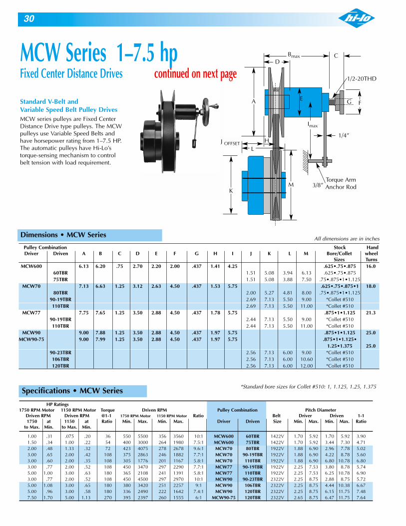
Specifications • MCW Series
Standard V-Belt and Variable Speed Belt Pulley DrivesMCW series pulleys are Fixed CenterDistance Drive type pulleys. The MCWpulleys use Variable Speed Belts andhave horsepower rating from 1–7.5 HP.The automatic pulleys have Hi-Lo’storque-sensing mechanism to controlbelt tension with load requirement.
Bmax C
1/2-20THD
Torque ArmAnchor Rod
1/4”J OFFSET
3/8”
G
D
EF
H
Imax
A
M
L
K
HP Ratings1750 RPM Motor 1150 RPM Motor Torque Driven RPM Pulley Combination Pitch Diameter
Driven RPM Driven RPM @1-1 1750 RPM Motor 1150 RPM Motor Ratio Belt Driver Driven 1-11750 at 1150 at Ratio Min. Max. Min. Max. Driver Driven Size Min. Max. Min. Max. Ratio
to Max. Min. to Max. Min.
1.00 .31 .075 .20 36 550 5500 356 3560 10:1 MCW600 60TBR 1422V 1.70 5.92 1.70 5.92 3.901.50 .34 1.00 .22 54 400 3000 264 1980 7.5:1 MCW600 75TBR 1422V 1.70 5.92 3.44 7.30 4.712.00 .48 1.33 .32 72 423 4075 278 2678 9.6:1 MCW70 80TBR 1922V 1.88 6.90 2.96 7.78 5.023.00 .65 2.00 .42 108 375 2863 246 1882 7.7:1 MCW70 90-19TBR 1922V 1.88 6.90 4.22 8.78 5.603.00 .60 2.00 .35 108 305 1776 201 1167 5.8:1 MCW70 110TBR 1922V 1.88 6.90 6.80 10.78 6.803.00 .77 2.00 .52 108 450 3470 297 2290 7.7:1 MCW77 90-19TBR 1922V 2.25 7.53 3.80 8.78 5.745.00 1.00 3.00 .63 180 365 2108 241 1391 5.8:1 MCW77 110TBR 1922V 2.25 7.53 6.25 10.78 6.903.00 .77 2.00 .52 108 450 4500 297 2970 10:1 MCW90 90-23TBR 2322V 2.25 8.75 2.88 8.75 5.725.00 1.08 3.00 .65 180 380 3420 251 2257 9:1 MCW90 106TBR 2322V 2.25 8.75 4.44 10.38 6.675.00 .96 3.00 .58 180 336 2490 222 1642 7.4:1 MCW90 120TBR 2322V 2.25 8.75 6.15 11.75 7.487.50 1.70 5.00 1.13 270 395 2397 260 1555 6:1 MCW90-75 120TBR 2322V 2.65 8.75 6.47 11.75 7.64
MCW Series 1–7.5 hpFixed Center Distance Drives continued on next page
*Standard bore sizes for Collet #510: 1, 1.125, 1.25, 1.375
All dimensions are in inches
Pulley Combination Stock HandDriver Driven A B C D E F G H I J K L M Bore/Collet wheel
Sizes TurnsMCW600 6.13 6.20 .75 2.70 2.20 2.00 .437 1.41 4.25 .625•.75•.875 16.0
60TBR 1.51 5.08 3.94 6.13 .625•.75•.87575TBR 1.51 5.08 3.88 7.50 .75•.875•1•1.125
MCW70 7.13 6.63 1.25 3.12 2.63 4.50 .437 1.53 5.75 .625•.75•.875•1 18.080TBR 2.00 5.27 4.81 8.00 .75•.875•1•1.125
90-19TBR 2.69 7.13 5.50 9.00 *Collet #510110TBR 2.69 7.13 5.50 11.00 *Collet #510
MCW77 7.75 7.65 1.25 3.50 2.88 4.50 .437 1.78 5.75 .875•1•1.125 21.390-19TBR 2.44 7.13 5.50 9.00 *Collet #510110TBR 2.44 7.13 5.50 11.00 *Collet #510
MCW90 9.00 7.88 1.25 3.50 2.88 4.50 .437 1.97 5.75 .875•1•1.125 25.0MCW90-75 9.00 7.99 1.25 3.50 2.88 4.50 .437 1.97 5.75 .875•1•1.125•
1.25•1.375 25.090-23TBR 2.56 7.13 6.00 9.00 *Collet #510106TBR 2.56 7.13 6.00 10.60 *Collet #510120TBR 2.56 7.13 6.00 12.00 *Collet #510
Dimensions • MCW Series

31
Pre-Engineered Belt and Center Distance Selection Chart • MCW Series
Pulley Combination 1922V Belt SizeDriver Driven 381 403 426 443 454 484 526 544 604 630 646 666 726 756
MCW70 80TBR 11.1 12.2 13.4 14.3 14.8 16.3 18.5 19.4 22.4 23.7 24.5 25.5 28.6 30.1MCW70 90-19TBR 10.1 11.2 12.5 13.3 13.9 15.4 17.6 18.5 21.5 22.9 23.7 24.7 27.7 29.2MCW70 110TBR 10.4 11.3 11.9 13.5 15.7 16.7 19.8 21.1 21.9 22.9 26.0 27.5MCW77 90-19TBR 10.0 11.1 12.3 13.1 13.7 15.2 17.3 18.2 21.2 22.5 23.3 24.3 27.3 28.8MCW77 110TBR 10.5 11.3 11.9 13.4 15.5 16.4 19.4 20.7 21.5 22.5 25.5 27.0
Pulley Combination 1422V Belt SizeDriver Driven 300 330 340 360 400 420 440 460 470 480 540 600 660 720
MCW600 60TBR 8.8 10.3 10.8 11.8 13.8 14.8 15.8 16.8 17.3 17.8 20.8 23.8 26.8 29.8MCW600 75TBR 7.6 9.1 9.6 10.6 12.6 13.6 14.6 15.6 16.1 16.6 19.6 22.6 25.6 28.6
L = (2C + 3.14D) C = (L - 3.14D)2
All dimensions are in inches.
To determine unlisted Belt Lengths and Center Distances, use these formulas:
C = Center DistanceD = 1 to 1 Pitch DiameterL = Belt Pitch Length
Pulley Combination 2322V Belt SizeDriver Driven 441 481 521 541 601 621 661 681 701 721 801 826 846 886
MCW90 90-23TBR 13.1 15.1 17.1 18.1 21.1 22.1 24.1 25.1 26.1 27.1 31.1 32.3 33.3 35.3MCW90 106TBR 11.6 13.6 15.6 16.6 19.6 20.6 22.6 23.6 24.6 25.6 29.6 30.8 31.8 33.8MCW90 120TBR 12.3 14.3 15.3 18.3 19.3 21.3 22.3 23.3 24.3 28.3 29.6 30.6 32.6
MCW90-75 120TBR 12.1 14.1 15.1 18.1 19.1 21.1 22.1 23.1 24.1 28.1 29.3 30.3 32.3
8.0
7.0
6.0
5.0
4.0
3.0
2.0
1.0
0 400 800 1200 1600 2000 2400 2800 3200 3600 4000 4400
MCW90-75 / 120TBR
MCW77 / 110TBR • MCW90 / 106TBR •
MCW90 120TBR
MCW70 / 90-19TBR • MCW70 / 110TBR
MCW77 / 90-19TBR • MCW90 / 90-23TBR
MCW70 / 80TBR
MCW600 / 75TBR
MCW600 / 60TBR
MCW600 Series
MCW77 and MCW70 Series
MCW90 and MCW90-75 Series
DRI
VEN
HO
RSEP
OW
ER
DRIVEN RPM
1750
Horsepower Curve • 1750 RPM Driver

32
Pulley Combination Stock Bores HandDriver Driven A B C D E F G H J P1 N O P2 Q R or Wheel
Collet Sizes Turns
MA82 8.27 3.94 4.0 .38 4.9 2.68 9.0 7.38 1.14 1•1.125•1.375 17.8A96 9.63 7.13 1.14 4.0 7.25 *Collet #512
MA96 9.63 5.12 6.0 .47 7.0 4.88 12.3 10.12 1.14 1.125•1.375•1.625 9.2A112 11.2 7.13 1.48 4.0 7.94 *Collet #512
MA112 11.2 5.12 6.0 .47 7.0 5.31 12.7 10.5 1.48 1.375•1.625 11.6A130 13.0 7.13 1.48 4.8 7.81 *Collet #7713
MA112-33 11.2 6.30 6.0 .63 7.5 5.00 13.3 10.8 1.32 1.625•1.875 10.7A130-33 13.0 7.13 1.48 4.8 8.25 *Collet #7713
All dimensions are in inches
Standard Bore Sizes for Collet #510: .75, .875, 1, 1.125, 1.25, 1.375#7713: 1.375, 1.5, 1.625, 1.875
RQ
P2
N O
A
G
C
B
EP1
F
JH
MA Series 5–30 hpAsymmetric Fixed Center Distance Drives continued on next page
Dimensions • MA Series 5–30 HP
Asymmetric Belt Pulley DrivesInstead of two identically angled V-shaped belt faces, Asymmetric VariableSpeed pulleys pair a V-angled face with a nearly flat (2º) fixed face. Theresulting design produces some important features
• Stable Belt Center Line:As the fixed pulley face is nearly perpendicular, the belt center linemovement throughout the entire pitch diameter range is negligible. Beltalignment with the driven sheave is maintained and crosswise wear on beltsis reduced.
• Compact and SimpleAsymmetric drives require a minimum of space in a C-Flow configurationrelative to their horsepower capacity. Installation alignment can be checkedsimply by laying a straight edge along the back of the fixed disks. Thereduction of parts in the single sliding face design minimizes the possibilityof a critical breakdown and simplifies repairs and replacement of parts.
• Stable and Low Overhung Load On BearingsThe C-Flow configuration of Asymmetric Drives and the nearlyperpendicular angle of the fixed pulley face locates the point of bendingmoment close to mounting shaft bearings. The peripheral support of the camand cam follower torque-sensing mechanism also reduces wear on thesliding face bearing surface. Use of interchangeable collet bushingseliminates side wobble and vibration due to bad fits between motor spindleand pulley shaft.
• Automatic Belt TensioningIncorporated in the automatic variable speed pulleys is Hi-Lo’s exclusivebelt-tensioning device. The cam and cam follower mechanism adjusts belttension to the load requirement and stabilizes the pitch diameter settingregardless of load fluctuations.

33
All dimensions are in inchesSpecifications • MA Series 5–30 HP
Pre-Engineered Belt and Center Distance Selection • MA Series 5–30 HP
32.0
28.0
24.0
20.0
16.0
12.0
8.0
4.0
400 800 1200 1600 2000 2400 2800 3200 3600
MA112-33 / A130-33
MA112 / A130
MA96 / A112
MA82 / A96
DRI
VEN
HO
RSEP
OW
ER
DRIVEN RPM
1750
Pulley Combination 23A Belt Section Pitch LengthsDriver Driven MM→ 1060 1100 1180 1250 1400 1500 1600 1700 1800 2000
Inches→ 41.7 43.3 46.5 49.3 55.2 59.2 63.0 66.9 71.9 78.7MA82 A96 C.D. 11.2 12.8 13.6 15.0 17.9 19.9 21.8 23.8 25.8 29.7
Pulley Combination 26A Belt Section Pitch LengthsDriver Driven MM→ 1250 1300 1400 1500 1600 1750 1800 1900 2000 2120 2400 2500 2650
Inches→ 49.3 51.2 55.2 59.2 63.0 68.9 70.9 74.8 78.7 83.5 94.5 98.4 104.3MA96 A112 C.D. 13.2 14.1 16.1 18.1 20.0 23.0 24.0 25.9 27.8 30.3 35.8 37.7 40.6MA112 A130 C.D. 12.5 14.5 16.5 18.4 21.3 22.3 24.3 26.2 28.6 34.1 36.1 39.0
Pulley Combination 33A Belt Section Pitch LengthsDriver Driven MM→ 1500 1600 1700 1750 1800 1900 2000 2120 2300 2400 2500 2650 2800
Inches→ 59.2 63.0 66.9 68.9 70.9 74.8 78.7 83.5 90.6 94.5 98.4 104.3 110.2MA112-33 A130-33 C.D. 16.2 18.1 20.0 21.0 22.0 24.0 25.9 28.3 31.9 33.8 35.8 38.7 41.7
HP Ratings1750 RPM 1150 RPM Torque Driven RPM Pulley Combination Pitch Diameter Driven RPM Driven RPM @1-1 1750 RPM 1150 RPM Ratio Belt Driver Driven 1-11750 at 1150 at Ratio Min. Max. Min. Max. Driver Driven Size Min. Max. Min. Max. Ratio
to Max. Min. to Max. Min.
5.00 1.50 3.00 1.00 180 500 3000 333 2000 6:1 MA82 A96 23A 2.76 7.88 4.32 9.24 6.1510.00 3.20 7.50 2.20 360 560 3000 373 2000 5.4:1 MA96 A112 26A 3.45 9.24 5.32 10.70 7.3215.00 4.30 10.00 2.90 540 500 3000 333 2000 6:1 MA112 A130 26A 3.55 10.7 5.82 12.40 8.3530.00 9.80 20.00 6.50 1080 600 3000 400 2000 5:1 MA112-33 A130-33 33A 4.20 10.7 6.25 12.40 8.54
To determine unlisted BeltLengths and Center Distances,use these formulas:L = (2C + 3.14D)
C = (L - 3.14D)2
C = Center DistanceD = 1:1 Pitch DiameterL = Belt Pitch Length
Horsepower Curve • 1750 RPM Driver

34
Pulley Combination Stock Bores HandDriver Driven A B C D E F G H J P1 N O P2 Q R or Wheel
Collet Sizes Turns
MA136 13.6 6.3 7.9 .63 7.7 4.3 13.2 11.7 1.75 1.625•1.875•2.125 15.9A164 1.00 16.4 7.28 1.75 5.5 10.2 SK
MA164 16.4 7.49 7.9 1.00 .67 9.0 5.5 14.7 12.9 1.75 SK 15.9A164 1.00 16.4 7.28 1.75 5.5 10.2 SK
MA164 16.4 7.49 7.9 1.00 .67 9.0 5.5 14.7 12.9 1.75 SK 15.9A177 1.13 17.7 8.98 2.50 5.5 13.6 SF
MA177 17.7 9.46 9.8 1.13 .79 9.7 5.5 17.0 15.0 2.5 SF 12.0A177 1.13 17.7 8.98 2.50 5.5 13.6 SF
MA177 17.7 9.46 9.8 1.13 .79 9.7 5.5 17.0 15.0 2.5 SF 12.0A221 1.13 22.1 10.0 2.50 6.7 15.0 SF
MA221 22.1 12.2 9.8 1.13 .79 11.8 6.6 22.0 17.9 2.5 SF 12.0A221 1.13 22.1 10.0 2.50 6.7 15.0 SF
All dimensions are in inches
R
O
QDP2
N
HOLDINGSCREW
REMOVALSCREW
A
G
C
B
EP1
F
JH
D
Dimensions • MA Series 40–125 HP
MA Series 40–125 hpAsymmetric Fixed Center Distance Drives continued on next page
Asymmetric Belt Pulley DrivesInstead of two identically angled V-shaped belt faces, Asymmetric VariableSpeed pulleys pair a V-angled face with a nearly flat (2º) fixed face. Theresulting design produces some important features:
• Stable Belt Center Line:As the fixed pulley face is nearly perpendicular, the belt center linemovement throughout the entire pitch diameter range is negligible. Beltalignment with the driven sheave is maintained and crosswise wear on beltsis reduced.
• Compact and SimpleAsymmetric drives require a minimum of space in a C-Flow configurationrelative to their horsepower capacity. Installation alignment can be checkedsimply by laying a straight edge along the back of the fixed disks. Thereduction of parts in the single sliding face design minimizes the possibilityof a critical breakdown and simplifies repairs and replacement of parts.
• Stable and Low Overhung Load On BearingsThe C-Flow configuration of Asymmetric Drives and the nearlyperpendicular angle of the fixed pulley face locates the point of bendingmoment close to mounting shaft bearings. The peripheral support of the camand cam follower torque-sensing mechanism also reduces wear on thesliding face bearing surface. Use of interchangeable collet bushingseliminates side wobble and vibration due to bad fits between motor spindleand pulley shaft.
• Automatic Belt TensioningIncorporated in the automatic variable speed pulleys is Hi-Lo’s exclusivebelt-tensioning device. The cam and cam follower mechanism adjusts belttension to the load requirement and stabilizes the pitch diameter settingregardless of load fluctuations.
Min. Max.
Standard Bore Sizes for Collet #510: .75, .875, 1, 1.125, 1.25, 1.375#7713: 1.375, 1.5, 1.625, 1.875

35
All dimensions are in inchesSpecifications • MA Series 40–125 HP
Pre-Engineered Belt and Center Distance Selection • MA Series 40–125 HP
128
112
96
80
64
48
32
16
400 800 1200 1600 2000 2400 2800 3200 3600
MA221 / A221
MA177 / A221
MA177 / A177
MA164 / A177
MA164 / A164
MA136 / A164
DRI
VEN
HO
RSEP
OW
ER
DRIVEN RPM (1750 RPM DRIVER)
1750
36A Belt section Pitch LengthsPulley CombinationMM 1800 1900 2000 2120 2250 2400 2500 2600 2700 2800 3000 3200Driver Driven
inches 70.9 74.8 78.7 83.5 88.6 94.5 98.4 102.4 106.3 110.2 118.1 126.0MA136 A164 C.D. 19.0 20.9 22.9 25.3 27.8 30.8 32.7 34.7 36.7 38.6 42.6 46.5MA164 A164 C.D. 17.2 19.2 21.2 23.5 26.1 29.3 31.0 33.0 34.9 36.9 40.8 44.8MA164 A177 C.D. 18.2 20.2 22.6 25.1 28.1 30.1 32.0 34.0 35.9 39.9 43.8MA177 A177 C.D. 18.2 20.5 23.1 26.1 28.0 30.0 32.0 33.9 37.9 41.8MA177 A221 C.D. 23.7 25.7 27.7 29.7 31.6 35.6 39.5MA221 A221 C.D. 29.7 33.7 37.6
HP Ratings1750 RPM 1150 RPM Torque Driven RPM Pulley Combination Pitch Diameter Driven RPM Driven RPM @1-1 1750 RPM 1150 RPM Ratio Belt Driver Driven 1-11750 at 1150 at Ratio Min. Max. Min. Max. Driver Driven Size Min. Max. Min. Max. Ratio
to Max. Min. to Max. Min.
40.00 11.40 25.00 7.60 1440 600 3000 400 2000 5:1 MA136 A164 36A 4.30 13.0 6.43 15.7 10.550.00 35.00 30.00 23.00 1800 784 3580 520 2340 4.5:1 MA164 A164 36A 6.43 15.7 6.43 15.7 11.660.00 30.00 40.00 19.00 2160 700 3220 460 2118 4.6:1 MA164 A177 36A 6.43 15.7 7.60 17.0 12.275.00 55.00 50.00 36.00 2700 1010 3000 670 1988 3:1 MA177 A177 36A 7.16 17.0 7.60 17.0 13.5
100.00 40.00 60.00 26.00 3600 595 2380 397 1597 4:1 MA177 A221 36A 7.16 17.0 12.50 21.5 15.0125.00 75.00 100.00 49.00 5400 838 2055 559 1370 2.5:1 MA221 A221 36A 10.00 17.4 14.80 21.5 16.2
To determine unlisted Belt Lengths andCenter Distances, use these formulas:L = (2C + 3.14D)C = (L - 3.14D)
2
C = Center DistanceD = 1 to 1 Pitch DiameterL = Belt Pitch Length
Horsepower Curve • 1750 RPM Driver

38VARI-Mod Performance Data
1.5
1.4
1.3
1.2
1.1
1.0
0.9
0.8
0.7
0.6
0.5
0.4
.0.3
0.2
0.1
800 1600 2400 3200 4000 4800
60
56
52
48
44
10
36
32
28
24
20
16
12
8
4
Torquein.-lbs. HP
Torquein.-lbs. HP
2.2
2.0
1.8
1.6
1.4
1.2
1.0
0.8
0.6
0.4
0.2
00400 800 1200 1600 2000 2400 2800
84
76
68
60
52
44
36
28
20
16
8
0
Torquein.-lbs. HP
Torquein.-lbs. HP
Transmission Ratings and Speed RangesModel *Output RPM *Output RPM Motor Output HP Output Torque (In.-lb.s) Output HP Output Torque (In.-lb.s)
1725 RPM 1140RPM HP 1725 RPM 1725 RPM 1140 RPM 1140 RPM Min. Max. Min. Max. Min. Max. Min. Max. Min. Max. Min. Max.
6060 550 4950 360 3270 .5 .11 .35 13 5 .11 .35 19 7.75 .21 .65 24 9 .21 .65 32 141 .28 .87 32 11 .28 .87 48 17
1.5 .41 1.30 47 17 NA NA NA NA6075 450 2700 300 1800 1.5 .35 1.35 49 32 .35 1.35 74 47
2 .46 1.80 65 42 NA NA NA NA
*When mounted to a reducer, the output RPM range is found by dividing the gearless range by the reducer ratio.
Model 6060 VARI-ModHorsepower and Torque Output Vs. 1750 RPM Motor Horsepower input
Model 6075 VARI-ModHorsepower and Torque Output Vs. 1750 RPM Motor Horsepower input
RPM
RPM
HorsepowerTorque
HorsepowerTorque
1.5 HP
1 HP
.75 HP
2 HP
1.5 HP
2 HP
1.5 HP
1.5 HP.5 HP
1 HP.75 HP.5 HP

39
Hi-Ratio Compound Pulleys for .25 and .5 HP drives provide economy and exceptional efficiency at speedratios up to 7 to 1. Pulley faces are made of highly durable plastic containing special additives to ensurelong service life.The pulley itself is comprised of two parts, either of which can be used independently. These are:
1. HR-2 Variable Speed Pulley Assembly which is needle-bearing mounted on a hardened andground countershaft. It requires a control of some type for operation.
2. HRB-2 Control Base. On the majority of applications, this base eliminates the necessity for apivoted motor base to maintain proper belt tension.
Operating PrincipleThe Hi-Ratio Pulley is needle-bearing mounted on a hardened and ground crankshaft. Speedvariation is accomplished by moving the countershaft between the driving and driven sheaves.Movement towards the driver (Fig. 1) reduces the driven speed. Movement away from the driver(Fig. 2) increases the driven speed..
Figure 1
Movement Approx. Wts.Hi-Ratio Belt Max. Min. Mean Required A B C D E FPulleys Ratio Size P.D. P.D. P.D. for Max. With Without
Speed Range Shaft Shaft
145HR-2 6-1 4L,A 4.60 1.875 3.25 2.125 6.5 3.875 4.75 1.19 .75 2.875 2.5 lbs. 1.75 lbs.
165HR-2 7.2-1 A 6.50 2.40 4.50 3.375 8.06 4.75 6.75 1.69 1.0 3.875 6 lbs. 4 lbs.
Hi–Ratio Compound Pulleys
Engineering Data
Figure 2
Figure 3

40
MOTOR OR DRIVER TO HI-RATIO PULLEY HI-RATIO PULLEY TO DRIVEN SHAFT
Belt Belt .Model Horse Power RPM. Sheave Center Belt Pitch Center Pitch Sheave Driven RPM
Max. Min. P.D. Distance Size Length Distance Length P.D. Max. Min.11.75 32.4 2.4 4290 71513.25 39.4 4.8 2120 360
145 .5 .25 1750 2.4 13.75 A 36.4 15.75 44.4 6.0 1720 286HR-2 15.0 49.4 9.0 1145 191
18.5 52.4 12.0 860 14313.25 36.4 3.0 4290 71513.25 39.4 4.8 2680 445
145 .5 .25 1750 3.0 13.25 A 36.4 15.75 44.4 6.0 2145 358HR-2 15.0 49.4 9.0 1430 238
18.5 52.4 12.0 1070 17914.25 39.4 3.6 4300 71513.25 39.4 4.8 3680 600
145 .5 .25 1750 3.6 12.875 A 36.4 15.75 44.4 6.0 2572 430HR-2 15.0 49.4 9.0 1715 286
18.5 52.4 12.0 1286 21511.75 36.4 3.6 3920 540
165 14.0 44.4 6.0 2370 330HR-2 1 .5 1750 3.0 14.125 A 40 15.5 52.4 9.0 1690 262
15.25 56.4 12.0 1185 16511.75 36.4 3.6 4700 650
165 1 .5 1750 3.6 13.625 A 40 14 44.4 6.0 2844 395HR-2 15.5 52.4 9.0 1890 262
15.25 56.4 12.0 1422 198165 13.25 39.3 4.2 4700 650
HR-2 1 .5 1750 4.2 13.25 A 40 15.0 49.4 8.0 2485 34515.25 56.4 12.0 1650 230
145 HR-2Max. RPM of Driven = P.D. Driver x 2.43 Motor x RPM.
P.D. Driven
Min. RPM of Driven = P.D. Driver x .41 x Motor RPM.P.D. Driven
145 HR-2Max. RPM of Driven = P.D. Driver x 2.70 Motor x RPM.
P.D. Driven
Min. RPM of Driven = P.D. Driver x .37 x Motor RPM.P.D. Driven
Engineering Data • Hi-Ratio Pulleys
All dimensions are in inchesHi-RatioControl 145HRB-2 165HRB-2Bases
A 11.75 11.75B 9.125 9.125C 5.375 5.375D 4.625 4.625E 1.5 1.5F 2.5 2.5G 4 4H 5 5I 3 3J .75 1K 4.25 4.25L .5 .5M 9.25 9.25N 2.625 2.625O 2.5 2.5P 3.625 3.625Q 1.75 1.75R 2 2S 0 0T 4 4
Approx.Weight 8.5 8.5
The output speeds areexamples of the manypossible variationsobtainable. By usingother sheave diameterson the driven shaft,many additional varia-tions are possible. Usethe formula below toderive speed ranges notcovered by the table.
HRB-2 Base
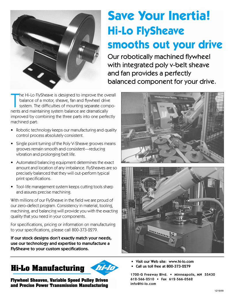
Flywheel Sheaves, Variable Speed Pulley Drivesand Precise Power Transmission Manufacturing
Save Your Inertia!Hi-Lo FlySheavesmooths out your driveOur robotically machined flywheelwith integrated poly v-belt sheave and fan provides a perfectly balanced component for your drive.
1700-G Freeway Blvd. • Minneapolis, MN 55430612-566-2510 • Fax [email protected]
• Visit our Web site: www.hi-lo.com• Call us toll free at 800-373-2279
The Hi-Lo FlySheave is designed to improve the overallbalance of a motor, sheave, fan and flywheel drivesystem. The difficulties of mounting separate compo-
nents and maintaining system balance are dramaticallyimproved by combining the three parts into one perfectlymachined part:
• Robotic technology keeps our manufacturing and qualitycontrol process absolutely consistent.
• Single point turning of the Poly V-Sheave grooves meansgrooves remain smooth and consistent—reducingvibration and prolonging belt life.
• Automated balancing equipment determines the exactamount and location of any imbalance. FlySheaves are soprecisely balanced that they will out-perform typicalprint specifications.
• Tool-life management system keeps cutting tools sharpand assures precise machining.
With millions of our FlySheave in the field we are proud ofour zero-defect program. Consistency in material, tooling,machining, and balancing will provide you with the exactingquality that you need in your components.
For specifications, pricing or information on manufacturingto your specifications, please call 800-373-2279.
If our stock designs don’t exactly match your needs,use our technology and expertise to manufacture aFlySheave to your custom specifications.
12/18/99

Visit our Web site for further and up-to-date information, including our downloadable product interchange with other manufacturers.
Look to Hi-Lo Manufacturing for any of your custom machining projects. Our modern facilities include state of the art robotics and the expertise to satisfy your engineering requirements.
42
04/02
30149 Stacy Ponds Drive, Suite 100Stacy, MN 55079
651-462-4580FAX [email protected]
www.hi-lo.com