power units for generator sets stage ii and non … deere.pdfpower units for generator sets stage ii...
TRANSCRIPT
Power Units forGenerator Sets
Stage II andNon-Certified Engines
(Saran-Built)
OPERATOR’S MANUALPower Units for Generator Sets
Stage II and Non-Certified Engines(Saran-Built)
OMCD16564 Issue F8 (ANGLAIS)
CALIFORNIAProposition 65 Warning
Diesel engine exhaust and some of its constituents areknown to the State of California to cause cancer, birth
defects, and other reproductive harm.
If this product contains a gasoline engine:
WARNING
The engine exhaust from this product contains chemicalsknown to the State of California to cause cancer, birth
defects or other reproductive harm.
The State of California requires the above two warnings.
John Deere Usine De Saran(This manual replaces OMCD16564 B7)
European VersionPrinted in Germany

Introduction
DPSG,CD03523,1 –19–05JUN08–1/2
Foreword
THIS MANUAL COVERS the following engines forgenerator sets:
Non Emission Certified Engines (Mechanical Fuel System)CD3029DF128CD3029TF158CD4039DF008CD4039TF008CD4045DF158CD4045HF158CD4045TF158CD4045TF258CD6068HF158CD6068HF258CD6068TF158CD6068TF258
Emission Certified Engines (Stage II according to Directive97/68/EC)CD3029HFS70 (Mechanical Fuel System)CD3029HFU70 (Mechanical Fuel System)CD3029TFS70 (Mechanical Fuel System)CD3029TFU70 (Mechanical Fuel System)CD4045HFS72 (DE10 Fuel System)CD4045HFS73 (HPCR System, 2-Valve Head)CD4045HFS80 (Mechanical Fuel System)CD4045HFS82 (HPCR System, 2-Valve Head)CD4045HFS83 (HPCR System, 2-Valve Head)CD4045HFU72 (DE10 Fuel System)CD4045HFU79 (HPCR System, 2-Valve Head)CD4045TFU70 (Mechanical Fuel System)CD6068HFS72 (DE10 Fuel System)CD6068HFS73 (HPCR System, 2-Valve Head)CD6068HFS76 (HPCR System, 4-Valve Head)CD6068HFS77 (HPCR System, 4-Valve Head)CD6068HFS82 (HPCR System, 2-Valve Head)CD6068HFS83 (HPCR System, 2-Valve Head)CD6068HFS89 (HPCR System, 4-Valve Head)CD6068HFU72 (DE10 Fuel System)CD6068HFU74 (HPCR System, 4-Valve Head)CD6068HFU79 (HPCR System, 2-Valve Head)
READ THIS MANUAL carefully to learn how to operateand service your engine correctly. Failure to do socould result in personal injury or equipment damage.
THIS MANUAL SHOULD BE CONSIDERED apermanent part of your engine and should remain withthe engine when you sell it.
MEASUREMENTS IN THIS MANUAL are given inmetric. Use only correct replacement parts andfasteners. Metric and inch fasteners may require aspecific metric or inch wrench.
WRITE ENGINE SERIAL NUMBERS and option codesin the spaces indicated in the Serial Number Section.Accurately record all the numbers. Your dealer alsoneeds these numbers when you order parts. File theidentification numbers in a secure place off the engineor machine.
RIGHT-HAND AND LEFT-HAND sides are determinedby standing at the drive or flywheel end (rear) of theengine and facing toward the front of the engine.
SETTING FUEL DELIVERY beyond published factoryspecifications or otherwise overpowering will result inloss of warranty protection for this engine.
Information relative to emissions regulationsDepending on final destination, this engine can meetthe emissions regulations according to the USEnvironmental Protection Agency (EPA), California AirResources Board (CARB) and for Europe, theDirective 97/68/EC relating the measures against theemissions of gaseous and particulates pollutants frominternal combustion engines. In this case an emissionlabel is stuck on the engine.
Emission regulations prohibit tampering with theemission-related components listed below which wouldrender that component inoperative or to make anyadjustment on the engine beyond publishedspecifications. It is also illegal to install a part orcomponent where the principal effect of thatcomponent is to bypass, defeat, or render inoperativeany engine component or device which would affectthe engine conformance to the emissions regulations.To summarize, it is illegal to do anything except returnthe engine to its original published specifications.
061208
PN=2

Introduction
DPSG,CD03523,1 –19–05JUN08–2/2
List of emission-related components:- Fuel injection pump- Intake manifold- Turbocharger- Charge air cooling system- Piston
CALIFORNIA PROPOSITION 65 WARNINGDiesel engine exhaust and some of its constituents are known to
the State of California to cause cancer,birth defects and other reproductive harm.
061208
PN=3

Introduction
061208
PN=4

ContentsPage Page
Identification Views Diesel Engine Break-In Oil . . . . . . . . . . . . . . . . . 10-3Identification views . . . . . . . . . . . . . . . . . . . . . . . 01-1 Diesel Engine Oil . . . . . . . . . . . . . . . . . . . . . . . . 10-4
Lubricant Storage . . . . . . . . . . . . . . . . . . . . . . . . 10-5Mixing of Lubricants . . . . . . . . . . . . . . . . . . . . . . 10-5Maintenance RecordsDiesel Engine Coolant . . . . . . . . . . . . . . . . . . . . 10-6Using maintenance records . . . . . . . . . . . . . . . . 02-1Operating in Warm Temperature Climates . . . . . 10-6100 Hours of operation. . . . . . . . . . . . . . . . . . . . 02-1
500 Hours of operation. . . . . . . . . . . . . . . . . . . . 02-21000 Hours of operation . . . . . . . . . . . . . . . . . . . 02-2 Operating the Engine1500 Hours of operation . . . . . . . . . . . . . . . . . . . 02-3 Using Diagnostic Gauge to Access2000 Hours of operation . . . . . . . . . . . . . . . . . . . 02-3 Engine Information (Optional equipment) . . . . 15-12500 Hours of operation . . . . . . . . . . . . . . . . . . . 02-4 Main Menu Navigation . . . . . . . . . . . . . . . . . . . . 15-23000 Hours of operation . . . . . . . . . . . . . . . . . . . 02-4 Engine Configuration Data . . . . . . . . . . . . . . . . . 15-43500 Hours of operation . . . . . . . . . . . . . . . . . . . 02-5 Accessing Stored Trouble Codes . . . . . . . . . . . . 15-64000 Hours of operation . . . . . . . . . . . . . . . . . . . 02-5 Accessing Active Trouble Codes . . . . . . . . . . . . 15-84500 Hours of operation . . . . . . . . . . . . . . . . . . . 02-6 Engine Shutdown Codes . . . . . . . . . . . . . . . . . 15-105000 Hours of operation . . . . . . . . . . . . . . . . . . . 02-6 Adjusting Backlighting. . . . . . . . . . . . . . . . . . . . 15-115500 Hours of operation . . . . . . . . . . . . . . . . . . . 02-7 Adjusting Contrast . . . . . . . . . . . . . . . . . . . . . . 15-136000 Hours of operation . . . . . . . . . . . . . . . . . . . 02-7 Selecting Units Of Measurement . . . . . . . . . . . 15-156500 Hours of operation . . . . . . . . . . . . . . . . . . . 02-8 Setup 1-Up Display . . . . . . . . . . . . . . . . . . . . . 15-187000 Hours of operation . . . . . . . . . . . . . . . . . . . 02-8 Setup 4-Up Display . . . . . . . . . . . . . . . . . . . . . 15-247500 Hours of operation . . . . . . . . . . . . . . . . . . . 02-9 Break-in period . . . . . . . . . . . . . . . . . . . . . . . . . 15-298000 Hours of operation . . . . . . . . . . . . . . . . . . . 02-9 Starting the engine . . . . . . . . . . . . . . . . . . . . . . 15-308500 Hours of operation . . . . . . . . . . . . . . . . . . 02-10 Cold weather operation . . . . . . . . . . . . . . . . . . 15-309000 Hours of operation . . . . . . . . . . . . . . . . . . 02-10 Using a booster battery or charger . . . . . . . . . . 15-339500 Hours of operation . . . . . . . . . . . . . . . . . . 02-11 Engine operation . . . . . . . . . . . . . . . . . . . . . . . 15-3410000 Hours of operation . . . . . . . . . . . . . . . . . 02-11 Standby power units . . . . . . . . . . . . . . . . . . . . . 15-34
Stopping the engine . . . . . . . . . . . . . . . . . . . . . 15-35Changing Generator Frequency . . . . . . . . . . . . 15-35Serial Numbers
POWERTech label . . . . . . . . . . . . . . . . . . . . . . 03-1Engine serial number plate. . . . . . . . . . . . . . . . . 03-1 MaintenanceRecord engine serial number . . . . . . . . . . . . . . . 03-2 Observe service intervals . . . . . . . . . . . . . . . . . . 20-1Engine option codes. . . . . . . . . . . . . . . . . . . . . . 03-3 Use correct fuels, lubricants and coolant . . . . . . 20-1Record fuel injection pump model number . . . . . 03-5 Maintenance interval chart . . . . . . . . . . . . . . . . . 20-2Record Engine Control Unit (ECU) Serial
Number. . . . . . . . . . . . . . . . . . . . . . . . . . . . . . 03-5 Maintenance/Daily or every 10 hoursRecord High-Pressure Fuel Pump Model Daily prestarting checks . . . . . . . . . . . . . . . . . . . 25-1
Number. . . . . . . . . . . . . . . . . . . . . . . . . . . . . . 03-5
Maintenance/500 hoursSafety . . . . . . . . . . . . . . . . . . . . . . . . . . . . . . . . 05-1 Changing engine oil and filter . . . . . . . . . . . . . . . 30-1
Replacing fuel filter element(s) . . . . . . . . . . . . . . 30-4Checking belt (3029 and 4039 Engines) . . . . . . . 30-6Fuels, Lubricants and Coolant
Diesel Fuel . . . . . . . . . . . . . . . . . . . . . . . . . . . . . 10-1Continued on next pageHandling and Storing Diesel Fuel . . . . . . . . . . . . 10-2
All information, illustrations and specifications in this manual are based onthe latest information available at the time of publication. The right isreserved to make changes at any time without notice.
COPYRIGHT 2008DEERE & COMPANY
European Office MannheimAll rights reserved
A John Deere ILLUSTRUCTION ManualPrevious EditionsCopyright 2007
i 061208
PN=1

Contents
Page Page
Checking belt (4045 and 6068 Engines with StorageEngine storage guidelines . . . . . . . . . . . . . . . . . 60-1manual tensioner) . . . . . . . . . . . . . . . . . . . . . . 30-7Preparing engine for long term storage . . . . . . . 60-1Removing engine from long term storage . . . . . . 60-2Maintenance/1000 hours/1 year
Cleaning crankcase vent tube . . . . . . . . . . . . . . 35-1SpecificationsChecking air intake system. . . . . . . . . . . . . . . . . 35-1General engine pack specificationsChecking automatic belt tensioner (4045
(Non-Emission Certified Engines) . . . . . . . . . . 65-1and 6068 Engines) . . . . . . . . . . . . . . . . . . . . . 35-2General engine pack specificationsCheck and adjust engine valve
(Stage II Emission Certified Engines) . . . . . . . 65-4clearance (3029 and 4039 Engines) . . . . . . . . 35-4Unified Inch Bolt and Screw Torque Values . . . . 65-9Pressure testing cooling system . . . . . . . . . . . . . 35-6Metric Bolt and Screw Torque Values. . . . . . . . 65-10
Maintenance/2000 hours/2 yearsCheck and adjust engine valve
clearance (4045 and 6068 Engines) . . . . . . . . 40-1Checking engine speed (Mechanical fuel
system) . . . . . . . . . . . . . . . . . . . . . . . . . . . . . . 40-3Adjust speed droop governor (Mechanical
fuel system) . . . . . . . . . . . . . . . . . . . . . . . . . . 40-3Checking crankshaft vibration damper
(6-CYLINDER ENGINE ONLY) . . . . . . . . . . . . 40-4
Maintenance/2500 hours/3 yearsDrain and flush cooling system. . . . . . . . . . . . . . 45-1
Maintenance/As requiredAdditional service information . . . . . . . . . . . . . . . 50-1Do not modify fuel system . . . . . . . . . . . . . . . . . 50-2Clean or replace air filter (one-piece) . . . . . . . . . 50-3Clean or replace air filter element. . . . . . . . . . . . 50-4Replacing fan and alternator belt (4045 and
6068 Engines). . . . . . . . . . . . . . . . . . . . . . . . . 50-5Bleeding the fuel system . . . . . . . . . . . . . . . . . . 50-6
TroubleshootingGeneral troubleshooting information . . . . . . . . . . 55-1Engine Wiring Layout (Electronic Fuel
System With Stanadyne DE10 InjectionPump) . . . . . . . . . . . . . . . . . . . . . . . . . . . . . . . 55-2
Engine Wiring Layout (Electronic FuelSystem With Denso High Pressure CommonRail) . . . . . . . . . . . . . . . . . . . . . . . . . . . . . . . . 55-3
Engine troubleshooting . . . . . . . . . . . . . . . . . . . . 55-4Electrical troubleshooting . . . . . . . . . . . . . . . . . . 55-9Displaying Of Diagnostic Trouble Codes
(DTCs) . . . . . . . . . . . . . . . . . . . . . . . . . . . . . 55-10Using blink code method for retrieving
Diagnostic Trouble Codes (DTC’s) . . . . . . . . 55-11Using diagnostic gauge for retrieving
Diagnostic Trouble Codes (DTC’s) . . . . . . . . 55-12Listing of Diagnostic Trouble Codes (DTCs) . . . 55-13Intermittent Fault Diagnostics (With
Electronic Controls). . . . . . . . . . . . . . . . . . . . 55-15
ii 061208
PN=2
Identification Views
DPSG,CD03523,3 –19–22JAN07–1/3
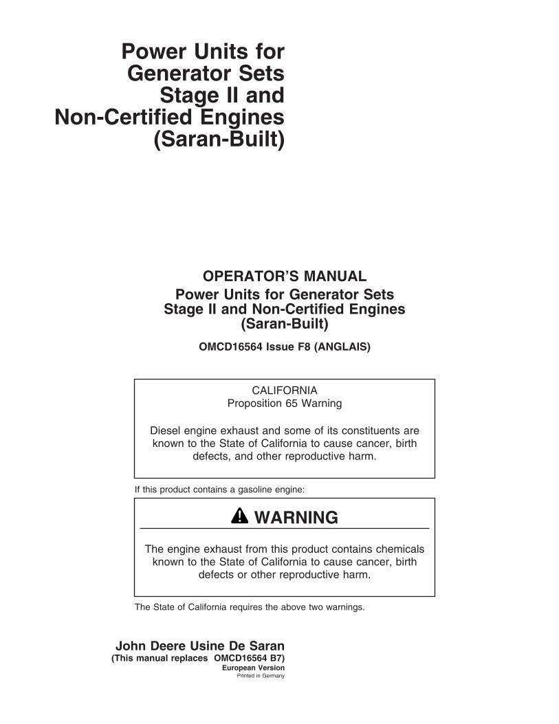
Identification views
CD
3084
0–U
N–1
0JA
N03
3029DF128
Continued on next page
01-1 061208
PN=7

Identification Views
DPSG,CD03523,3 –19–22JAN07–2/3C
D30
841
–UN
–10J
AN
03
4045HF158
Continued on next page
01-2 061208
PN=8

Identification Views
DPSG,CD03523,3 –19–22JAN07–3/3C
D30
842
–UN
–10J
AN
03
6068HF258
01-3 061208
PN=9

Maintenance Records
DPSG,CD03523,6 –19–22JAN07–1/1
Using maintenance records
To obtain the best performance, economy and servicelife from your engine, ensure service is carried outaccording to this present manual and recorded in thefollowing pages. It is recommended that your engineDistributor or your Dealer carry out this service workand stamp the appropriate case.
Keeping an accurate account of all service performedon your engine will give more value to the machinewhen resell it.
John Deere oils and coolants have been formulated togive maximum protection and performance to yourengine. We recommend only genuine John Deereservice products and replacement parts.
To protect your rights under the warranty ensure allscheduled services are carried out and recorded. Ifyour engine is covered by extended warranty, it isimportant to maintain this record for the duration of thewarranty.
DPSG,CD03523,7 –19–22JAN07–1/1
100 Hours of operation
❒ Engine oil, drain
❒ Engine oil filter, replace
❒ Hose connections, check
Number of hours: Observation: Dealer or distributor stamp
Date:
Job done by:
02-1 061208
PN=10

Maintenance Records
DPSG,CD03523,8 –19–22JAN07–1/1
500 Hours of operation
❒ Engine oil, drain
❒ Engine oil filter, replace
❒ Fuel filter, replace
❒ Belt, check tension and wear (300-Series and POWERTech withmanual tensioner)
❒ Valve clearance, adjust (300-Series)
Number of hours: Observation: Dealer or distributor stamp
Date:
Job done by:
DPSG,CD03523,9 –19–22JAN07–1/1
1000 Hours of operation
❒ Engine oil, drain ❒ Air intake system, check
❒ Engine oil filter, replace
❒ Fuel filter, replace
❒ Check belt and tensioning system
❒ Crankcase vent tube, clean
Number of hours: Observation: Dealer or distributor stamp
Date:
Job done by:
02-2 061208
PN=11
Maintenance Records
DPSG,CD03523,10 –19–22JAN07–1/1
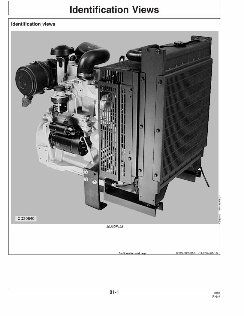
1500 Hours of operation
❒ Engine oil, drain
❒ Engine oil filter, replace
❒ Fuel filter, replace
❒ Belt, check tension and wear (300-Series and POWERTech withmanual tensioner)
❒ Valve clearance, adjust (300-Series)
Number of hours: Observation: Dealer or distributor stamp
Date:
Job done by:
DPSG,CD03523,59 –19–22JAN07–1/1
2000 Hours of operation
❒ Engine oil, drain ❒ Cooling system, drain and flush (if COOL-GARD is not used)
❒ Engine oil filter, replace ❒ Valve clearance, adjust (POWERTech)
❒ Fuel filter, replace ❒ Air intake system, check
❒ Check belt and tensioning system ❒ Vibration damper, check
❒ Crankcase vent tube, clean
Number of hours: Observation: Dealer or distributor stamp
Date:
Job done by:
02-3 061208
PN=12

Maintenance Records
DPSG,CD03523,60 –19–22JAN07–1/1
2500 Hours of operation
❒ Engine oil, drain ❒ Cooling system, drain and flush (if COOL-GARD is used)
❒ Engine oil filter, replace
❒ Fuel filter, replace
❒ Belt, check tension and wear (300-Series and POWERTech withmanual tensioner)
❒ Valve clearance, adjust (300-Series)
Number of hours: Observation: Dealer or distributor stamp
Date:
Job done by:
DPSG,CD03523,61 –19–22JAN07–1/1
3000 Hours of operation
❒ Engine oil, drain ❒ Air intake system, check
❒ Engine oil filter, replace
❒ Fuel filter, replace
❒ Check belt and tensioning system
❒ Crankcase vent tube, clean
Number of hours: Observation: Dealer or distributor stamp
Date:
Job done by:
02-4 061208
PN=13

Maintenance Records
DPSG,CD03523,62 –19–22JAN07–1/1
3500 Hours of operation
❒ Engine oil, drain
❒ Engine oil filter, replace
❒ Fuel filter, replace
❒ Belt, check tension and wear (300-Series and POWERTech withmanual tensioner)
❒ Valve clearance, adjust (300-Series)
Number of hours: Observation: Dealer or distributor stamp
Date:
Job done by:
DPSG,CD03523,63 –19–22JAN07–1/1
4000 Hours of operation
❒ Engine oil, drain ❒ Cooling system, drain and flush (if COOL-GARD is not used)
❒ Engine oil filter, replace ❒ Valve clearance, adjust (POWERTech)
❒ Fuel filter, replace ❒ Air intake system, check
❒ Check belt and tensioning system ❒ Vibration damper, check
❒ Crankcase vent tube, clean
Number of hours: Observation: Dealer or distributor stamp
Date:
Job done by:
02-5 061208
PN=14

Maintenance Records
DPSG,CD03523,64 –19–22JAN07–1/1
4500 Hours of operation
❒ Engine oil, drain ❒ Vibration damper, replace (6 cyl.)
❒ Fuel filter, replace
❒ Belt, check tension and wear (300-Series and POWERTech withmanual tensioner)
❒ Valve clearance, adjust (300-Series)
Number of hours: Observation: Dealer or distributor stamp
Date:
Job done by:
DPSG,CD03523,65 –19–22JAN07–1/1
5000 Hours of operation
❒ Engine oil, drain ❒ Injection nozzles, replace
❒ Engine oil filter, replace ❒ Air intake system, check
❒ Fuel filter, replace ❒ Cooling system, drain and flush (if COOL-GARD is used)
❒ Check belt and tensioning system
❒ Crankcase vent tube, clean
Number of hours: Observation: Dealer or distributor stamp
Date:
Job done by:
02-6 061208
PN=15

Maintenance Records
DPSG,CD03523,66 –19–22JAN07–1/1
5500 Hours of operation
❒ Engine oil, drain
❒ Engine oil filter, replace
❒ Fuel filter, replace
❒ Belt, check tension and wear (300-Series and POWERTech withmanual tensioner)
❒ Valve clearance, adjust (300-Series)
Number of hours: Observation: Dealer or distributor stamp
Date:
Job done by:
DPSG,CD03523,67 –19–22JAN07–1/1
6000 Hours of operation
❒ Engine oil, drain ❒ Cooling system, drain and flush (if COOL-GARD is not used)
❒ Engine oil filter, replace ❒ Valve clearance, adjust (POWERTech)
❒ Fuel filter, replace ❒ Air intake system, check
❒ Check belt and tensioning system ❒ Vibration damper, check
❒ Crankcase vent tube, clean
Number of hours: Observation: Dealer or distributor stamp
Date:
Job done by:
02-7 061208
PN=16

Maintenance Records
DPSG,CD03523,68 –19–22JAN07–1/1
6500 Hours of operation
❒ Engine oil, drain
❒ Engine oil filter, replace
❒ Fuel filter, replace
❒ Belt, check tension and wear (300-Series and POWERTech withmanual tensioner)
❒ Valve clearance, adjust (300-Series)
Number of hours: Observation: Dealer or distributor stamp
Date:
Job done by:
DPSG,CD03523,69 –19–22JAN07–1/1
7000 Hours of operation
❒ Engine oil, drain ❒ Air intake system, check
❒ Engine oil filter, replace
❒ Fuel filter, replace
❒ Check belt and tensioning system
❒ Crankcase vent tube, clean
Number of hours: Observation: Dealer or distributor stamp
Date:
Job done by:
02-8 061208
PN=17

Maintenance Records
DPSG,CD03523,70 –19–22JAN07–1/1
7500 Hours of operation
❒ Engine oil, drain ❒ Cooling system, drain and flush (if COOL-GARD is used)
❒ Engine oil filter, replace
❒ Fuel filter, replace
❒ Belt, check tension and wear (300-Series and POWERTech withmanual tensioner)
❒ Valve clearance, adjust (300-Series)
Number of hours: Observation: Dealer or distributor stamp
Date:
Job done by:
DPSG,CD03523,71 –19–22JAN07–1/1
8000 Hours of operation
❒ Engine oil, drain ❒ Cooling system, drain and flush (if COOL-GARD is not used)
❒ Engine oil filter, replace ❒ Valve clearance, adjust (POWERTech)
❒ Fuel filter, replace ❒ Air intake system, check
❒ Check belt and tensioning system ❒ Vibration damper, check
❒ Crankcase vent tube, clean
Number of hours: Observation: Dealer or distributor stamp
Date:
Job done by:
02-9 061208
PN=18

Maintenance Records
DPSG,CD03523,72 –19–22JAN07–1/1
8500 Hours of operation
❒ Engine oil, drain
❒ Engine oil filter, replace
❒ Fuel filter, replace
❒ Belt, check tension and wear (300-Series and POWERTech withmanual tensioner)
❒ Valve clearance, adjust (300-Series)
Number of hours: Observation: Dealer or distributor stamp
Date:
Job done by:
DPSG,CD03523,73 –19–22JAN07–1/1
9000 Hours of operation
❒ Engine oil, drain ❒ Air intake system, check
❒ Engine oil filter, replace
❒ Fuel filter, replace
❒ Check belt and tensioning system
❒ Crankcase vent tube, clean
Number of hours: Observation: Dealer or distributor stamp
Date:
Job done by:
02-10 061208
PN=19

Maintenance Records
DPSG,CD03523,74 –19–22JAN07–1/1
9500 Hours of operation
❒ Engine oil, drain
❒ Engine oil filter, replace
❒ Fuel filter, replace
❒ Belt, check tension and wear (300-Series and POWERTech withmanual tensioner)
❒ Valve clearance, adjust (300-Series)
Number of hours: Observation: Dealer or distributor stamp
Date:
Job done by:
DPSG,CD03523,75 –19–22JAN07–1/1
10000 Hours of operation
❒ Engine oil, drain ❒ Cooling system, drain and flush
❒ Engine oil filter, replace ❒ Valve clearance, adjust (POWERTech)
❒ Fuel filter, replace ❒ Thermostat, replace
❒ Check belt and tensioning system ❒ Vibration damper, check
❒ Crankcase vent tube, clean ❒ Injection nozzles, replace
❒ Air intake system, check
Number of hours: Observation: Dealer or distributor stamp
Date:
Job done by:
02-11 061208
PN=20

Serial Numbers
DPSG,CD03523,11 –19–22JAN07–1/1
POWERTech label
RG
8041
–UN
–15J
AN
99
A label is located on the rocker arm cover which identifieseach engine as a John Deere POWERTECH engine.
POWERTECH is a trademark of Deere & Company
DPSG,CD03523,12 –19–22JAN07–1/1
Engine serial number plateR
G80
07–U
N–1
5JA
N99
4045 and 6068 Engines
CD
3074
6–U
N–2
4SE
P99
3029 and 4039 Engines
Each engine has a 13–digit John Deere serial number.The first two digits identify the factory that producedthe engine:
”CD” indicates the engine was built in Saran, France
Your engine’s serial number plate (A) is located on theright-hand side of cylinder block behind the fuel filterfor 4045 and 6068 engines and near the fuel supplypump on 3029 and 4039 engines.
03-1 061208
PN=21

Serial Numbers
DPSG,CD03523,13 –19–22JAN07–1/1
Record engine serial number
CD
3070
5B–U
N–2
4AU
G99
3029 and 4039 engine plate
CD
3074
7A–U
N–2
2JA
N07
4045 and 6068 engine plate
Record all of the numbers and letters found on yourengine serial number plate in the spaces provided below.
This information is very important for repair parts orwarranty information.
Engine Serial Number (B)
___________________
Engine Model Number (C)
___________________
Coefficient of Absorption Value (D)
___________________
03-2 061208
PN=22

Serial Numbers
DPSG,CD03523,14 –19–22JAN07–1/2
Engine option codes
CD
3074
8A–U
N–2
6AU
G99
Engine option code label
In addition to the serial number plate, OEM engineshave an engine option code label affixed to the rockerarm cover. These codes indicate which of the engineoptions were installed on your engine at the factory.When in need of parts or service, furnish yourauthorized servicing dealer or engine distributor withthese numbers.
An additional sticker may be also delivered (in a plasticbag attached to the engine or inserted in the machinedocumentation). It is recommended to stick this optioncode list sticker either:
• On this page of your Operator’s manual below thissection.
or• On the ”Engine Owner’s Warranty” booklet under the
title OPTION CODES (Engine manufacturingconfiguration).
NOTE: The Machine Manufacturer may have alreadystuck it at a specific accessible place (insidethe enclosure or close to a maintenance area).
The engine option code label includes an engine basecode (A). This base code must also be recorded alongwith the option codes. At times it will be necessary tofurnish this base code to differentiate two identicaloption codes for the same engine model.
The first two digits of each code identify a specificgroup, such as alternators. The last two digits of each
code identify one specific option provided on yourengine, such as a 12-volt, 55-amp alternator.
NOTE: These option codes are based on the latestinformation available at the time of publication.The right is reserved to make changes at anytime without notice.
If an engine is ordered without a particular component,the last two digits of that functional group option codewill be 99, 00, or XX. The list on the next page showsonly the first two digits of the code numbers. For futurereference such as ordering repair parts, it is importantto have these code numbers available. To ensure thisavailability, enter the third and fourth digits shown onyour engine option code label in the spaces providedon the following page.
03-3 061208
PN=23
Continued on next page

Serial Numbers
DPSG,CD03523,14 –19–22JAN07–2/2
NOTE: NOTE: Your engine option code label may notcontain all option codes if an option has beenadded after the engine left the producingfactory.
If option code label is lost or destroyed,consult your servicing dealer or enginedistributor selling the engine for a replacement.
Option Description Option DescriptionCodes Codes
Engine Base Code:________
11____ Rocker Arm Cover 50____ Oil Pump12____ Oil Filler Neck 51____ Cylinder Head With Valves13____ Crankshaft Pulley 52____ Auxiliary Gear Drive14____ Flywheel Housing 53____ Fuel Heater15____ Flywheel 54____ Oil heater16____ Fuel Injection Pump 55____ Shipping stand17____ Air inlet 56____ Paint Option18____ Air cleaner 57____ Coolant Inlet19____ Oil pan 59____ Oil Cooler20____ Coolant pump 60____ Add-on Auxiliary Drive Pulley21____ Thermostat Cover 62____ Alternator Mounting22____ Thermostat 63____ Low Pressure Fuel Line23____ Fan Drive 64____ Exhaust Elbow24____ Fan Belt 65____ Turbocharger25____ Fan 66____ Temperature Switch26____ Engine Coolant Heater 67____ Electronic Tachometer Sensor27____ Radiator 68____ Damper28____ Exhaust Manifold 69____ Engine Serial Number Plate29____ Ventilator System 72____ ECU Electronic Software Option30____ Starting Motor 74____ Air conditioner Compressor Mounting31____ Alternator 75____ Air Restriction Indicator32____ Instrument Panel 76____ Oil Pressure Switch35____ Fuel Filter 81____ Primary Fuel Filter36____ Front Plate 83____ Electronic Software37____ Fuel Transfer Pump 84____ Electrical Wiring Harness39____ Thermostat Housing 86____ Fan Pulley40____ Oil Dipstick 87____ Automatic Belt Tensioner41____ Belt Driven Front Auxiliary Drive 88____ Oil Filter43____ Starting Aid 91____ Special Equipment (Factory Installed)44____ Timing Gear Cover with Gears 94____ Vehicle Timing45____ Balancer Shaft 95____ Identification label46____ Cylinder Block With Liners and Camshaft 97____ Special Equipment (Field Installed)47____ Crankshaft and Bearings 98____ Shipping48____ Connecting Rods and Pistons49____ Valve Actuating Mechanisms
03-4 061208
PN=24

Serial Numbers
DPSG,CD03523,15 –19–22JAN07–1/1
Record fuel injection pump model number
CD
3074
9–U
N–2
4SE
P99
Record the fuel injection pump model and serialinformation found on the serial number plate (A).
Model No. _____________________ RPM _______
Manufacturer’s No. __________________________
Serial No. _________________________________
CD03523,0000189 –19–06FEB07–1/1
Record Engine Control Unit (ECU) SerialNumber
RG
1463
5–U
N–1
3AP
R06
Record Engine Control Unit (ECU) Serial Number
A—Serial Number Label
Record the part number and serial number informationfound on the serial number label (A) on the EngineControl Unit (ECU) mounted on or near the engine.
Part No.
Serial No.
CD03523,000018A –19–06FEB07–1/1
Record High-Pressure Fuel Pump ModelNumber
RG
1371
8–U
N–1
1NO
V04
Record High-Pressure Fuel Pump Serial NumberA—Serial Number Plate
Record the high-pressure fuel pump model and serialnumber information found on the serial number plate (A).
Model No. RPM
Manufacturer’s No.
Serial No.
03-5 061208
PN=25
Safety
DX,ALERT –19–29SEP98–1/1
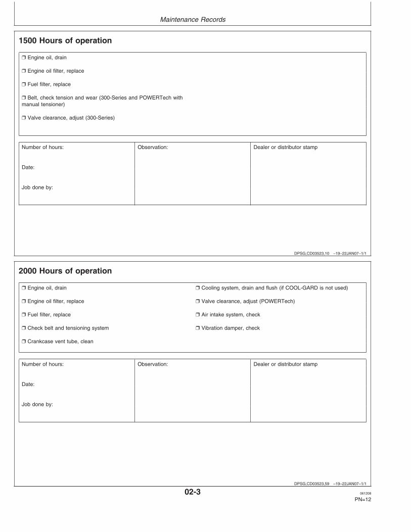
Recognize Safety Information
T81
389
–UN
–07D
EC
88
This is a safety-alert symbol. When you see this symbolon your machine or in this manual, be alert to thepotential for personal injury.
Follow recommended precautions and safe operatingpractices.
DX,SIGNAL –19–03MAR93–1/1
Understand Signal Words
TS
187
–19–
30S
EP
88
A signal word—DANGER, WARNING, or CAUTION—isused with the safety-alert symbol. DANGER identifies themost serious hazards.
DANGER or WARNING safety signs are located nearspecific hazards. General precautions are listed onCAUTION safety signs. CAUTION also calls attention tosafety messages in this manual.
DX,WW,HPCR1 –19–07JAN03–1/1
Do Not Open High-Pressure Fuel System
TS
1343
–UN
–18M
AR
92
High-pressure fluid remaining in fuel lines can causeserious injury. Do not disconnect or attempt repair of fuellines, sensors, or any other components between thehigh-pressure fuel pump and nozzles on engines withHigh Pressure Common Rail (HPCR) fuel system.
Only technicians familiar with this type of system canperform repairs. (See your John Deere dealer.)
05-1 061208
PN=26
Safety
DPSG,CD03523,95 –19–22JAN07–1/1
Engine lifting procedure
RG
7784
–UN
–11N
OV
97
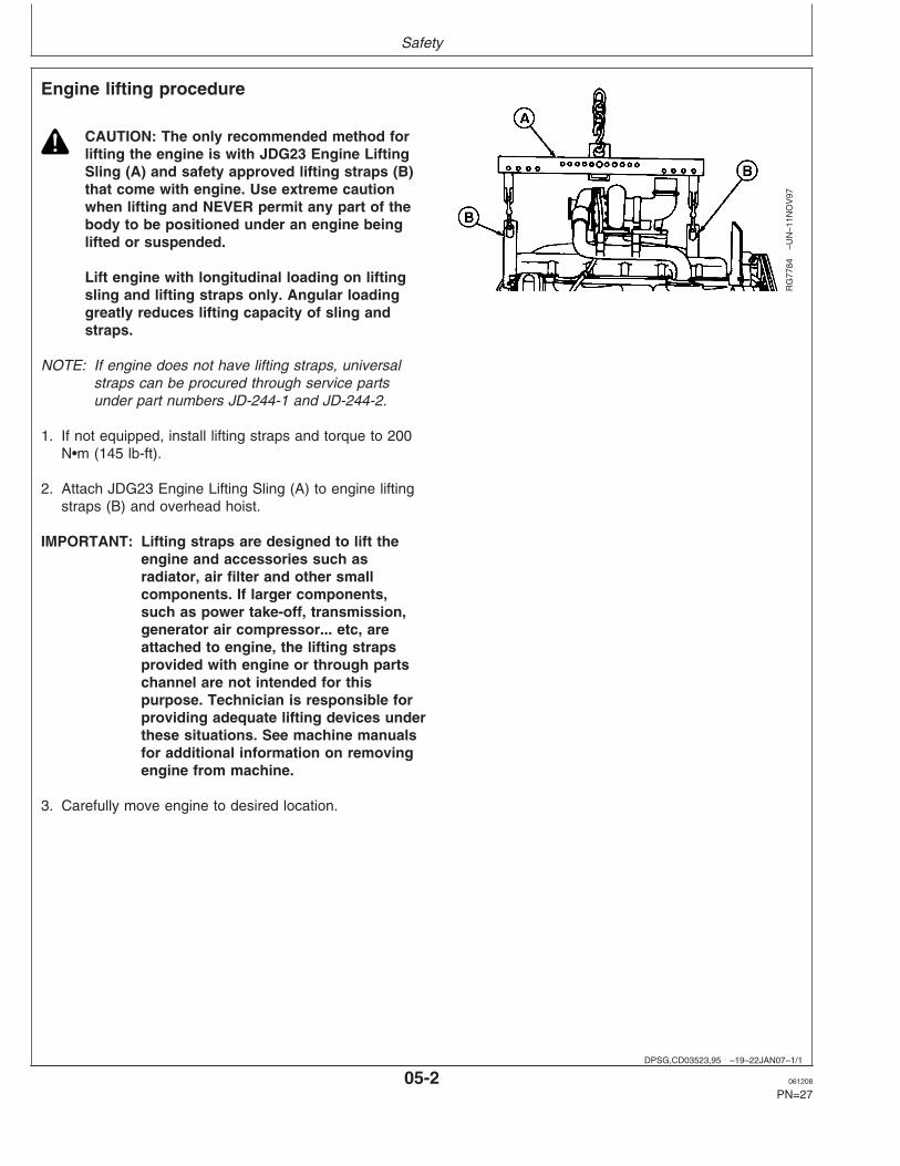
CAUTION: The only recommended method forlifting the engine is with JDG23 Engine LiftingSling (A) and safety approved lifting straps (B)that come with engine. Use extreme cautionwhen lifting and NEVER permit any part of thebody to be positioned under an engine beinglifted or suspended.
Lift engine with longitudinal loading on liftingsling and lifting straps only. Angular loadinggreatly reduces lifting capacity of sling andstraps.
NOTE: If engine does not have lifting straps, universalstraps can be procured through service partsunder part numbers JD-244-1 and JD-244-2.
1. If not equipped, install lifting straps and torque to 200N•m (145 lb-ft).
2. Attach JDG23 Engine Lifting Sling (A) to engine liftingstraps (B) and overhead hoist.
IMPORTANT: Lifting straps are designed to lift theengine and accessories such asradiator, air filter and other smallcomponents. If larger components,such as power take-off, transmission,generator air compressor... etc, areattached to engine, the lifting strapsprovided with engine or through partschannel are not intended for thispurpose. Technician is responsible forproviding adequate lifting devices underthese situations. See machine manualsfor additional information on removingengine from machine.
3. Carefully move engine to desired location.
05-2 061208
PN=27

Safety
DX,READ –19–03MAR93–1/1
Follow Safety Instructions
TS
201
–UN
–23A
UG
88
Carefully read all safety messages in this manual and onyour machine safety signs. Keep safety signs in goodcondition. Replace missing or damaged safety signs. Besure new equipment components and repair parts includethe current safety signs. Replacement safety signs areavailable from your John Deere dealer.
Learn how to operate the machine and how to usecontrols properly. Do not let anyone operate withoutinstruction.
Keep your machine in proper working condition.Unauthorized modifications to the machine may impair thefunction and/or safety and affect machine life.
If you do not understand any part of this manual and needassistance, contact your John Deere dealer.
DX,BYPAS1 –19–29SEP98–1/1
Prevent Machine Runaway
TS
177
–UN
–11J
AN
89
Avoid possible injury or death from machinery runaway.
Do not start engine by shorting across starter terminals.Machine will start in gear if normal circuitry is bypassed.
NEVER start engine while standing on ground. Startengine only from operator’s seat, with transmission inneutral or park.
05-3 061208
PN=28

Safety
DX,FIRE1 –19–03MAR93–1/1
Handle Fuel Safely—Avoid Fires
TS
202
–UN
–23A
UG
88
Handle fuel with care: it is highly flammable. Do not refuelthe machine while smoking or when near open flame orsparks.
Always stop engine before refueling machine. Fill fuel tankoutdoors.
Prevent fires by keeping machine clean of accumulatedtrash, grease, and debris. Always clean up spilled fuel.
DX,FIRE2 –19–03MAR93–1/1
Prepare for Emergencies
TS
291
–UN
–23A
UG
88
Be prepared if a fire starts.
Keep a first aid kit and fire extinguisher handy.
Keep emergency numbers for doctors, ambulance service,hospital, and fire department near your telephone.
DX,FIRE3 –19–16APR92–1/1
Handle Starting Fluid Safely
TS
1356
–UN
–18M
AR
92
Starting fluid is highly flammable.
Keep all sparks and flame away when using it. Keepstarting fluid away from batteries and cables.
To prevent accidental discharge when storing thepressurized can, keep the cap on the container, and storein a cool, protected location.
Do not incinerate or puncture a starting fluid container.
05-4 061208
PN=29
Safety
DX,WEAR –19–10SEP90–1/1
Wear Protective Clothing
TS
206
–UN
–23A
UG
88
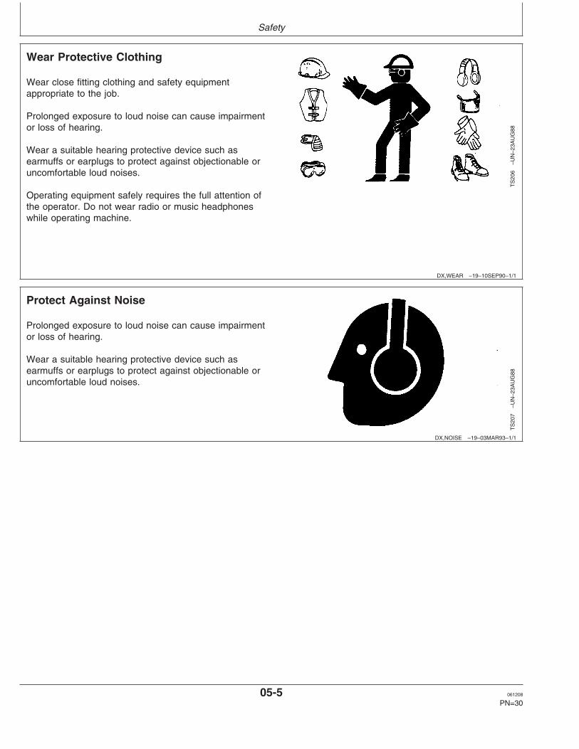
Wear close fitting clothing and safety equipmentappropriate to the job.
Prolonged exposure to loud noise can cause impairmentor loss of hearing.
Wear a suitable hearing protective device such asearmuffs or earplugs to protect against objectionable oruncomfortable loud noises.
Operating equipment safely requires the full attention ofthe operator. Do not wear radio or music headphoneswhile operating machine.
DX,NOISE –19–03MAR93–1/1
Protect Against Noise
TS
207
–UN
–23A
UG
88
Prolonged exposure to loud noise can cause impairmentor loss of hearing.
Wear a suitable hearing protective device such asearmuffs or earplugs to protect against objectionable oruncomfortable loud noises.
05-5 061208
PN=30

Safety
DX,MSDS,NA –19–03MAR93–1/1
Handle Chemical Products Safely
TS
1132
–UN
–26N
OV
90
Direct exposure to hazardous chemicals can causeserious injury. Potentially hazardous chemicals used withJohn Deere equipment include such items as lubricants,coolants, paints, and adhesives.
A Material Safety Data Sheet (MSDS) provides specificdetails on chemical products: physical and health hazards,safety procedures, and emergency response techniques.
Check the MSDS before you start any job using ahazardous chemical. That way you will know exactly whatthe risks are and how to do the job safely. Then followprocedures and recommended equipment.
(See your John Deere dealer for MSDS’s on chemicalproducts used with John Deere equipment.)
CD,PTO –19–22JAN07–1/1
Stay Clear of Rotating Drivelines
TS
1644
–UN
–22A
UG
95
Entanglement in rotating driveline can cause serious injuryor death.
Keep master shield and driveline shields in place at alltimes. Make sure rotating shields turn freely.
Wear close fitting clothing. Stop the engine and be surethe PTO driveline is stopped before making adjustmentsor performing any type service on the engine orPTO-driven equipment.
05-6 061208
PN=31

Safety
DX,SERV –19–17FEB99–1/1
Practice Safe Maintenance
TS
218
–UN
–23A
UG
88
Understand service procedure before doing work. Keeparea clean and dry.
Never lubricate, service, or adjust machine while it ismoving. Keep hands, feet , and clothing frompower-driven parts. Disengage all power and operatecontrols to relieve pressure. Lower equipment to theground. Stop the engine. Remove the key. Allow machineto cool.
Securely support any machine elements that must beraised for service work.
Keep all parts in good condition and properly installed. Fixdamage immediately. Replace worn or broken parts.Remove any buildup of grease, oil, or debris.
On self-propelled equipment, disconnect battery groundcable (-) before making adjustments on electrical systemsor welding on machine.
On towed implements, disconnect wiring harnesses fromtractor before servicing electrical system components orwelding on machine.
DX,AIR –19–17FEB99–1/1
Work In Ventilated Area
TS
220
–UN
–23A
UG
88
Engine exhaust fumes can cause sickness or death. If it isnecessary to run an engine in an enclosed area, removethe exhaust fumes from the area with an exhaust pipeextension.
If you do not have an exhaust pipe extension, open thedoors and get outside air into the area.
05-7 061208
PN=32

Safety
DX,FLUID –19–03MAR93–1/1
Avoid High-Pressure Fluids
X98
11–U
N–2
3AU
G88
Escaping fluid under pressure can penetrate the skincausing serious injury.
Avoid the hazard by relieving pressure beforedisconnecting hydraulic or other lines. Tighten allconnections before applying pressure.
Search for leaks with a piece of cardboard. Protect handsand body from high pressure fluids.
If an accident occurs, see a doctor immediately. Any fluidinjected into the skin must be surgically removed within afew hours or gangrene may result. Doctors unfamiliar withthis type of injury should reference a knowledgeablemedical source. Such information is available from Deere& Company Medical Department in Moline, Illinois, U.S.A.
DX,TORCH –19–10DEC04–1/1
Avoid Heating Near Pressurized Fluid Lines
TS
953
–UN
–15M
AY
90
Flammable spray can be generated by heating nearpressurized fluid lines, resulting in severe burns toyourself and bystanders. Do not heat by welding,soldering, or using a torch near pressurized fluid lines orother flammable materials. Pressurized lines canaccidentally burst when heat goes beyond the immediateflame area.
05-8 061208
PN=33

Safety
DX,PAINT –19–24JUL02–1/1
Remove Paint Before Welding or Heating
TS
220
–UN
–23A
UG
88
Avoid potentially toxic fumes and dust.
Hazardous fumes can be generated when paint is heatedby welding, soldering, or using a torch.
Remove paint before heating:
• Remove paint a minimum of 100 mm (4 in.) from areato be affected by heating. If paint cannot be removed,wear an approved respirator before heating or welding.
• If you sand or grind paint, avoid breathing the dust.Wear an approved respirator.
• If you use solvent or paint stripper, remove stripper withsoap and water before welding. Remove solvent orpaint stripper containers and other flammable materialfrom area. Allow fumes to disperse at least 15 minutesbefore welding or heating.
Do not use a chlorinated solvent in areas where weldingwill take place.
Do all work in an area that is well ventilated to carry toxicfumes and dust away.
Dispose of paint and solvent properly.
DX,RCAP –19–04JUN90–1/1
Service Cooling System Safely
TS
281
–UN
–23A
UG
88
Explosive release of fluids from pressurized coolingsystem can cause serious burns.
Shut off engine. Only remove filler cap when cool enoughto touch with bare hands. Slowly loosen cap to first stopto relieve pressure before removing completely.
05-9 061208
PN=34
Safety
DX,DUST –19–15MAR91–1/1
Avoid Harmful Asbestos Dust
TS
220
–UN
–23A
UG
88
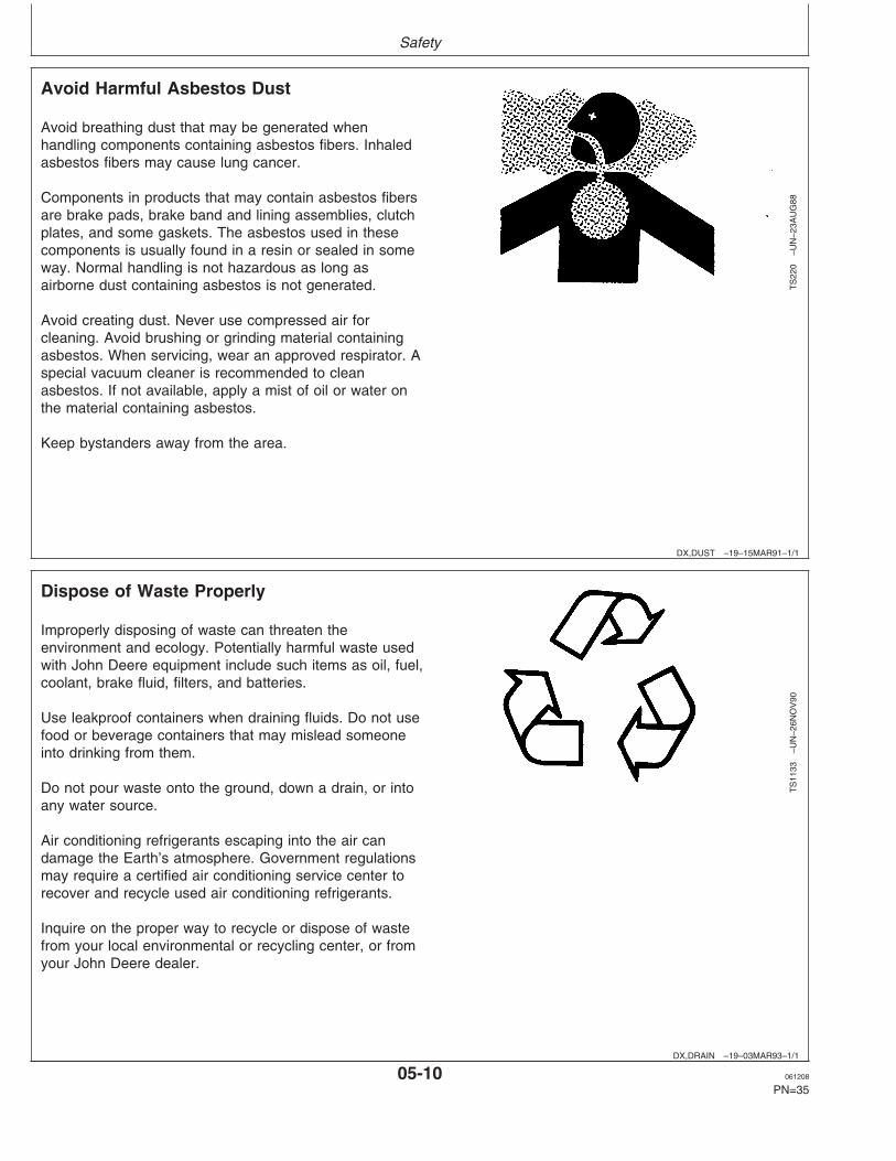
Avoid breathing dust that may be generated whenhandling components containing asbestos fibers. Inhaledasbestos fibers may cause lung cancer.
Components in products that may contain asbestos fibersare brake pads, brake band and lining assemblies, clutchplates, and some gaskets. The asbestos used in thesecomponents is usually found in a resin or sealed in someway. Normal handling is not hazardous as long asairborne dust containing asbestos is not generated.
Avoid creating dust. Never use compressed air forcleaning. Avoid brushing or grinding material containingasbestos. When servicing, wear an approved respirator. Aspecial vacuum cleaner is recommended to cleanasbestos. If not available, apply a mist of oil or water onthe material containing asbestos.
Keep bystanders away from the area.
DX,DRAIN –19–03MAR93–1/1
Dispose of Waste Properly
TS
1133
–UN
–26N
OV
90
Improperly disposing of waste can threaten theenvironment and ecology. Potentially harmful waste usedwith John Deere equipment include such items as oil, fuel,coolant, brake fluid, filters, and batteries.
Use leakproof containers when draining fluids. Do not usefood or beverage containers that may mislead someoneinto drinking from them.
Do not pour waste onto the ground, down a drain, or intoany water source.
Air conditioning refrigerants escaping into the air candamage the Earth’s atmosphere. Government regulationsmay require a certified air conditioning service center torecover and recycle used air conditioning refrigerants.
Inquire on the proper way to recycle or dispose of wastefrom your local environmental or recycling center, or fromyour John Deere dealer.
05-10 061208
PN=35

Fuels, Lubricants and Coolant
DX,FUEL1 –19–05OCT07–1/1
Diesel Fuel
Consult your local fuel distributor for properties of thediesel fuel available in your area.
In general, diesel fuels are blended to satisfy the lowtemperature requirements of the geographical area inwhich they are marketed.
Diesel fuels specified to EN 590 or ASTM D975 arerecommended. Renewable diesel is basically identicalto petroleum diesel fuel that is created byHydrotreating fats and oils. Renewable diesel thatmeets EN 590 or ASTM D975 is acceptable for use atall percentage mixture levels.
Required fuel properties
In all cases, the fuel shall meet the followingproperties:
Cetane number of 45 minimum. Cetane numbergreater than 50 is preferred, especially fortemperatures below –20°C (–4°F) or elevations above1500 m (5000 ft).
Cold Filter Plugging Point (CFPP) should be at least5°C (9°F) below the expected lowest temperature orCloud Point below the expected lowest ambienttemperature.
Fuel lubricity should pass a maximum scar diameterof 0.45 mm as measured by ASTM D6079 or ISO12156-1.
Sulfur content:
• Diesel fuel quality and fuel sulfur content mustcomply with all existing emissions regulations for thearea in which the engine operates.
• Use of diesel fuel with sulfur content less than0.10% (1000 ppm) is STRONGLY recommended.
• Use of diesel fuel with sulfur content 0.10% (1000ppm) to 0.50% (5000 ppm) may result in REDUCEDoil and filter change intervals as shown in the table.
• BEFORE using diesel fuel with sulfur content greaterthan 0.50% (5000 ppm), contact your John Deeredealer.
IMPORTANT: Do not mix used diesel engine oil orany other type of lubricating oil withdiesel fuel.
IMPORTANT: Improper fuel additive usage maycause damage on fuel injectionequipment of diesel engines.
10-1 061208
PN=36
Fuels, Lubricants and Coolant
DX,FUEL4 –19–19DEC03–1/1
Handling and Storing Diesel Fuel
CAUTION: Handle fuel carefully. Do not fillthe fuel tank when engine is running.
DO NOT smoke while you fill the fuel tank orservice the fuel system.
Fill the fuel tank at the end of each day’s operation toprevent water condensation and freezing during coldweather.
Keep all storage tanks as full as practicable tominimize condensation.
Ensure that all fuel tank caps and covers are installedproperly to prevent moisture from entering.
Monitor water content of the fuel regularly.
When using bio-diesel fuel, the fuel filter may requiremore frequent replacement due to premature plugging.
Check engine oil level daily prior to starting engine. Arising oil level may indicate fuel dilution of the engineoil.
IMPORTANT: The fuel tank is vented through thefiller cap. If a new filler cap isrequired, always replace it with anoriginal vented cap.
When fuel is stored for an extended period or if thereis a slow turnover of fuel, add a fuel conditioner tostabilize the fuel and prevent water condensation.Contact your fuel supplier for recommendations.
10-2 061208
PN=37

Fuels, Lubricants and Coolant
DX,ENOIL4 –19–13SEP06–1/1
Diesel Engine Break-In Oil
New engines are filled at the factory with John DeereENGINE BREAK-IN OIL. During the break-in period,add John Deere ENGINE BREAK-IN OIL as needed tomaintain the specified oil level.
Change the oil and filter after the first 100 hours ofoperation of a new or rebuilt engine.
After engine overhaul, fill the engine with John DeereENGINE BREAK-IN OIL.
If John Deere ENGINE BREAK-IN OIL is not available,use a diesel engine oil meeting one of the followingduring the first 100 hours of operation:
• API Service Classification CE• API Service Classification CD• API Service Classification CC• ACEA Oil Sequence E2• ACEA Oil Sequence E1
After the break-in period, use John Deere PLUS-50or other diesel engine oil as recommended in thismanual.
IMPORTANT: Do not use PLUS-50 oil or engineoils meeting any of the followingduring the first 100 hours ofoperation of a new or rebuilt engine:
API CJ-4 ACEA E7API CI-4 PLUS ACEA E6API CI-4 ACEA E5API CH-4 ACEA E4API CG-4 ACEA E3API CF-4API CF-2API CF
These oils will not allow the engineto break-in properly.
PLUS-50 is a trademark of Deere & Company.
10-3 061208
PN=38

Fuels, Lubricants and Coolant
CD,ENOIL –19–25JAN07–1/1
Diesel Engine Oil
TS
1675
–UN
–09O
CT
06
Oil Viscosities for Air Temperature Ranges
Use oil viscosity based on the expected air temperaturerange during the period between oil changes.
Depending on Emission Regulation requirements, the oilrecommendations are different. Refer to the chart toidentify the proper oil to be used.
Non Emission Certified Engines Stage II Emission CertifiedEngines
John Deere PLUS-50 John Deere PLUS-50(Preferred) (Preferred)
John Deere TORQ-GARD John Deere TORQ-GARDSUPREME SUPREME
ACEA-E3, ACEA-E2 ACEA-E7, ACEA-E6, ACEA-E5,ACEA-E4, ACEA-E3
API-CH4, API-CG4, API-CF4 API-CJ4, API-CI4 PLUS, API-CI4,API-CH4
Multi-viscosity diesel engine oils are preferred.
If diesel fuel with sulfur content greater than 0.5% is usedor if oil does not meet the classification above, reduce theservice interval by 50%.
DO NOT use diesel fuel with sulfur content greater than1%.
PLUS-50 is a trademark of Deere & CompanyTORQ-GARD SUPREME is a trademark of Deere & Company
10-4 061208
PN=39

Fuels, Lubricants and Coolant
DX,LUBST –19–18MAR96–1/1
Lubricant Storage
Your equipment can operate at top efficiency onlywhen clean lubricants are used.
Use clean containers to handle all lubricants.
Whenever possible, store lubricants and containers inan area protected from dust, moisture, and othercontamination. Store containers on their side to avoidwater and dirt accumulation.
Make certain that all containers are properly marked toidentify their contents.
Properly dispose of all old containers and any residuallubricant they may contain.
DX,LUBMIX –19–18MAR96–1/1
Mixing of Lubricants
In general, avoid mixing different brands or types of oil.Oil manufacturers blend additives in their oils to meetcertain specifications and performance requirements.
Mixing different oils can interfere with the properfunctioning of these additives and degrade lubricantperformance.
Consult your John Deere dealer to obtain specificinformation and recommendations.
10-5 061208
PN=40

Fuels, Lubricants and Coolant
DX,COOL8 –19–16NOV01–1/1
Diesel Engine Coolant
The engine cooling system is filled to provideyear-round protection against corrosion and cylinderliner pitting, and winter freeze protection to -37°C(-34°F).
John Deere COOL-GARD is preferred for service.
If John Deere COOL-GARD is not available, use a lowsilicate ethylene glycol or propylene glycol basecoolant concentrate in a 50% mixture of concentratewith quality water.
The coolant concentrate shall be of a quality thatprovides cavitation protection to cast iron andaluminum parts in the cooling system. John DeereCOOL-GARD meets this requirement.
Freeze protection
A 50% mixture of ethylene glycol engine coolant inwater provides freeze protection to -37°C (-34°F).
A 50% mixture of propylene glycol engine coolant inwater provides freeze protection to -33°C (-27°F).
If protection at lower temperatures is required, consultyour John Deere dealer for recommendations.
Water quality
Water quality is important to the performance of thecooling system. Distilled, deionized, or demineralizedwater is recommended for mixing with ethylene glycoland propylene glycol base engine coolant concentrate.
IMPORTANT: Do not use cooling system sealingadditives or antifreeze that containssealing additives.
IMPORTANT: Do not mix ethylene glycol andpropylene glycol base coolants.
DX,COOL6 –19–18MAR96–1/1
Operating in Warm Temperature Climates
John Deere engines are designed to operate usingglycol base engine coolants.
Always use a recommended glycol base enginecoolant, even when operating in geographical areaswhere freeze protection is not required.
IMPORTANT: Water may be used as coolant inemergency situations only.
Foaming, hot surface aluminum andiron corrosion, scaling, andcavitation will occur when water isused as the coolant, even whencoolant conditioners are added.
Drain cooling system and refill withrecommended glycol base enginecoolant as soon as possible.
10-6 061208
PN=41

Operating the Engine
CD03523,000018B –19–22JAN07–1/2
Using Diagnostic Gauge to Access EngineInformation (Optional equipment)
RG
1313
2–U
N–0
9SE
P03
Diagnostic Gauge
A—Diagnostic GaugeB—Menu KeyC—Arrow KeysD—Enter KeyE—Red ”STOP ENGINE” Indicator LightF—Amber ”WARNING” Indicator Light
NOTE: Generator sets powered by an electronicallycontrolled engine (DE10 or HPCR fuel system)can be optionally equipped with the diagnosticgauge shown. Depending on the generator setmanufacturer, other instrumentations can be used.Refer to the generator set documentation for moreinformation.
The diagnostic gauge (A) allows the operator to viewmany readouts of engine functions and trouble codes(DTCs). The gauge is linked to the electronic controlsystem and its sensors. This allows the operator tomonitor engine functions and to troubleshoot the enginesystems when needed.
Press the menu key (B) to access the various enginefunctions in sequence. The displays can be selected aseither customary English or metric units. The followingmenu of engine parameters can be displayed on thediagnostic gauge window:
• Engine hours• Engine rpm• System voltage• Percent engine load at the current rpm• Coolant temperature• Oil pressure• Throttle position• Intake manifold temperature• Current fuel consumption• Active service (diagnostic) codes• Stored service (diagnostic) codes from the engine• Set the units for display• View the engine configuration parameters
Continued on next page
15-1 061208
PN=42

Operating the Engine
CD03523,000018B –19–22JAN07–2/2
NOTE: Engine parameters which can be accessed willvary with the engine application. Six languages forreadouts are available and can be selected duringsetup of gauge.
The diagnostic gauge includes a graphical backlit LiquidCrystal Display (LCD) screen. The display can show eithera single parameter or a quadrant display showing fourparameters simultaneously. The diagnostic gauge usestwo arrow keys (C) for scrolling through the engineparameter list and viewing the menu list and an enter key(D) for selecting highlighted items. The red (E) and amber(F) lights are used to signal active trouble code receivedby the diagnostic gauge.
OURGP11,00000A9 –19–03SEP03–1/5
Main Menu Navigation
RG
1315
9–U
N–2
6SE
P03
Menu Key
NOTE: The engine does not need to be running tonavigate the diagnostic gauge screens. If enginestart up is desired, See Starting The Engine. All ofthe engine values illustrated on the diagnosticgauge indicate the engine is running.
1. Turn the key switch to the ON position. Starting at thesingle or four engine parameter display, press the"Menu" key.
OURGP11,00000A9 –19–03SEP03–2/5
RG
1316
0–U
N–0
2OC
T03
Menu Display
2. The first seven items of the "Main Menu" will bedisplayed.
15-2 061208
PN=43
Continued on next page
Operating the Engine
OURGP11,00000A9 –19–03SEP03–3/5
RG
1316
1–U
N–0
2OC
T03
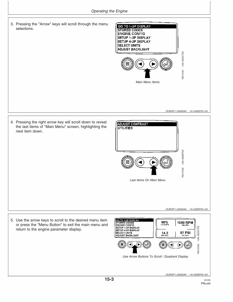
Main Menu Items
3. Pressing the "Arrow" keys will scroll through the menuselections.
OURGP11,00000A9 –19–03SEP03–4/5
RG
1316
2–U
N–2
6SE
P03
Last Items On Main Menu
4. Pressing the right arrow key will scroll down to revealthe last items of "Main Menu" screen, highlighting thenext item down.
OURGP11,00000A9 –19–03SEP03–5/5
RG
1316
3–U
N–0
2OC
T03
Use Arrow Buttons To Scroll / Quadrant Display
5. Use the arrow keys to scroll to the desired menu itemor press the "Menu Button" to exit the main menu andreturn to the engine parameter display.
15-3 061208
PN=44

Operating the Engine
OURGP11,00000AB –19–03SEP03–1/6
Engine Configuration Data
RG
1315
9–U
N–2
6SE
P03
Menu Key
NOTE: The engine configuration data is a read onlyfunction.
NOTE: The engine does not need to be running tonavigate the diagnostic gauge screens. If enginestart up is desired, See Starting The Engine. All ofthe engine values illustrated on the diagnosticgauge indicate the engine is running.
1. Turn the key switch to the ON position. Starting at thesingle or four engine parameter display, press the"Menu" key.
OURGP11,00000AB –19–03SEP03–2/6
RG
1316
4–U
N–0
7OC
T03
Select Engine Configuration
2. The main menu will be displayed. Use the "Arrow" keysto scroll through the menu until "Engine Config" ishighlighted.
OURGP11,00000AB –19–03SEP03–3/6
RG
1316
5–U
N–0
2OC
T03
Enter Key
3. Once "Engine Config" menu item has been highlighted,press the "Enter" key to view the engine configurationdata.
Continued on next page
15-4 061208
PN=45
Operating the Engine
OURGP11,00000AB –19–03SEP03–4/6
RG
1316
6–U
N–2
9SE
P03
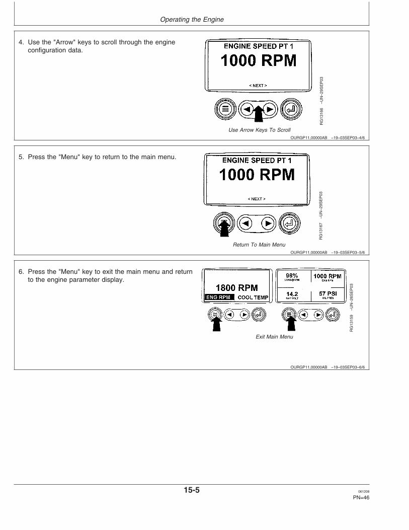
Use Arrow Keys To Scroll
4. Use the "Arrow" keys to scroll through the engineconfiguration data.
OURGP11,00000AB –19–03SEP03–5/6
RG
1316
7–U
N–2
9SE
P03
Return To Main Menu
5. Press the "Menu" key to return to the main menu.
OURGP11,00000AB –19–03SEP03–6/6
RG
1315
9–U
N–2
6SE
P03
Exit Main Menu
6. Press the "Menu" key to exit the main menu and returnto the engine parameter display.
15-5 061208
PN=46
Operating the Engine
OURGP11,00000AC –19–03SEP03–1/6
Accessing Stored Trouble Codes
RG
1315
9–U
N–2
6SE
P03
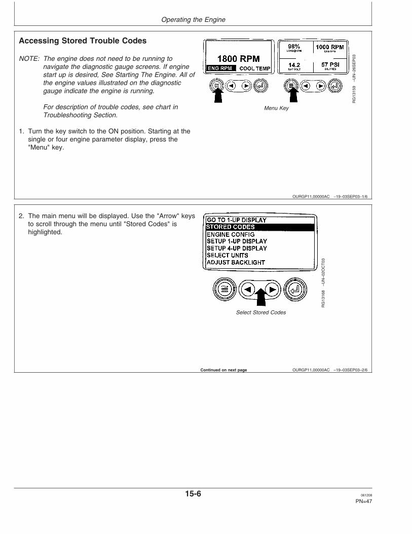
Menu Key
NOTE: The engine does not need to be running tonavigate the diagnostic gauge screens. If enginestart up is desired, See Starting The Engine. All ofthe engine values illustrated on the diagnosticgauge indicate the engine is running.
For description of trouble codes, see chart inTroubleshooting Section.
1. Turn the key switch to the ON position. Starting at thesingle or four engine parameter display, press the"Menu" key.
OURGP11,00000AC –19–03SEP03–2/6
RG
1316
8–U
N–0
2OC
T03
Select Stored Codes
2. The main menu will be displayed. Use the "Arrow" keysto scroll through the menu until "Stored Codes" ishighlighted.
Continued on next page
15-6 061208
PN=47

Operating the Engine
OURGP11,00000AC –19–03SEP03–3/6
RG
1316
9–U
N–0
2OC
T03
Enter Key
3. Once the "Stored Codes" menu item has beenhighlighted press the "Enter" key to view the storedcodes.
OURGP11,00000AC –19–03SEP03–4/6
RG
1324
5–U
N–0
2OC
T03
Use Arrow Keys To Scroll
4. If the word "Next" appears above the "Arrow" keys,there are more stored codes that may be viewed. Usethe "Arrow" key to scroll to the next stored code.
OURGP11,00000AC –19–03SEP03–5/6
RG
1324
6–U
N–0
2OC
T03
Return To Main Menu
5. Press the "Menu" key to return to the main menu.
Continued on next page
15-7 061208
PN=48

Operating the Engine
OURGP11,00000AC –19–03SEP03–6/6
RG
1315
9–U
N–2
6SE
P03
Exit Main Menu
6. Press the "Menu" key to exit the main menu and returnto the engine parameter display.
OURGP11,00000AD –19–03SEP03–1/7
Accessing Active Trouble Codes
RG
1317
2–U
N–2
6SE
P03
Normal Operation
NOTE: The engine does not need to be running tonavigate the diagnostic gauge screens. If enginestart up is desired, See Starting The Engine. All ofthe engine values illustrated on the diagnosticgauge indicate the engine is running.
For description of trouble codes, see chart inTroubleshooting Section.
1. During normal operation the single or four parameterscreen will be displayed.
OURGP11,00000AD –19–03SEP03–2/7
RG
1324
0–U
N–3
0SE
P03
Active Trouble Codes Displayed
2. When the diagnostic gauge receives a trouble codefrom an engine control unit, the single or fourparameter screen will be replaced with the "Warning"message. The SPN and FMI number will be displayedalong with a description of the problem and thecorrective action needed.
IMPORTANT: Ignoring active trouble codes can resultin severe engine damage.
Continued on next page
15-8 061208
PN=49

Operating the Engine
OURGP11,00000AD –19–03SEP03–3/7
RG
1324
1–U
N–3
0SE
P03
Use Arrow Keys To Scroll
3. If the word "Next" appears above the arrow keys, thereare more trouble codes that can be viewed by usingthe arrow keys to scroll to the next trouble code.
OURGP11,00000AD –19–03SEP03–4/7
RG
1324
2–U
N–3
0SE
P03
Hide Trouble Codes
IMPORTANT: Ignoring active trouble codes can resultin severe engine damage.
4. To acknowledge and hide the code and return to thesingle or four parameter display, press the "Enter" Key.
OURGP11,00000AD –19–03SEP03–5/7
RG
1317
6–U
N–2
6SE
P03
Active Trouble Code Icon
5. The display will return to the single or four parameterdisplay, but the display will contain the warning icon.Pressing the "Enter" key will redisplay the hiddentrouble code.
OURGP11,00000AD –19–03SEP03–6/7
RG
1324
2–U
N–3
0SE
P03
Enter Key
IMPORTANT: Ignoring active trouble codes can resultin severe engine damage.
6. Pressing the "Enter" key once again will hide thetrouble code and return the screen to the single or fourparameter display.
15-9 061208
PN=50
Continued on next page

Operating the Engine
OURGP11,00000AD –19–03SEP03–7/7
RG
1324
3–U
N–0
1OC
T03
Active Trouble Code Condition
7. The single or four parameter screen will display thewarning icon until the trouble code condition iscorrected.
OURGP11,00000AE –19–03SEP03–1/6
Engine Shutdown Codes
RG
1317
2–U
N–2
6SE
P03
Normal Operation
1. During normal operation the single or four parameterscreen will be displayed.
OURGP11,00000AE –19–03SEP03–2/6
RG
1323
8–U
N–2
9SE
P03
Shutdown Message
2. When the diagnostic gauge receives a severe troublecode from an engine control unit, the single or fourparameter screen will be replaced with the "Shutdown"message. The SPN and FMI number will be displayedalong with a description of the problem and thecorrective action needed.
If the word "Next" appears above the arrow keys, thereare more trouble codes that can be viewed by usingthe arrow keys to scroll to the next trouble code.
OURGP11,00000AE –19–03SEP03–3/6
RG
1323
9–U
N–2
9SE
P03
Hide Trouble Code
3. To acknowledge and hide the trouble code and returnto the single or four parameter display, press the"Enter" key".
IMPORTANT: Ignoring the shutdown message canresult in severe engine damage.
15-10 061208
PN=51
Continued on next page

Operating the Engine
OURGP11,00000AE –19–03SEP03–4/6
RG
1317
9–U
N–2
6SE
P03
Flashing Shutdown Icon
4. The display will return to the single or four parameterdisplay, but the display will contain the "Shutdown"icon. Pressing the "Enter" key will redisplay the hiddentrouble code.
IMPORTANT: Ignoring the shutdown message canresult in severe engine damage.
OURGP11,00000AE –19–03SEP03–5/6
RG
1323
9–U
N–2
9SE
P03
Redisplay Trouble Code
5. Pressing the "Enter" key once again will hide thetrouble code and return the screen to the single or fourparameter display.
OURGP11,00000AE –19–03SEP03–6/6
RG
1318
0–U
N–2
6SE
P03
Shutdown Icon
6. The single or four parameter screen will display theshutdown icon until the trouble code condition iscorrected.
IMPORTANT: Ignoring the shutdown message canresult in severe engine damage.
OURGP11,0000237 –19–21OCT03–1/6
Adjusting Backlighting
RG
1315
9–U
N–2
6SE
P03
Menu Key
1. Turn the key switch to the ON position. Starting at thesingle or four engine parameter display, press the"Menu" key.
15-11 061208
PN=52
Continued on next page

Operating the Engine
OURGP11,0000237 –19–21OCT03–2/6
RG
1318
1–U
N–0
2OC
T03
Select Adjust Backlight
2. The main menu will be displayed. Use the "Arrow" keysto scroll through the menu until "Adjust Backlight" ishighlighted.
OURGP11,0000237 –19–21OCT03–3/6
RG
1318
2–U
N–0
2OC
T03
Press Enter Key
3. Once the "Adjust Backlight" menu item has beenhighlighted, press the "Enter" key to activate the"Adjust Backlight" function.
OURGP11,0000237 –19–21OCT03–4/6
RG
1318
3–U
N–2
9SE
P03
Adjust Backlight Intensity
4. Use the "Arrow" keys to select the desired backlightintensity.
Continued on next page
15-12 061208
PN=53
Operating the Engine
OURGP11,0000237 –19–21OCT03–5/6
RG
1318
4–U
N–2
6SE
P03
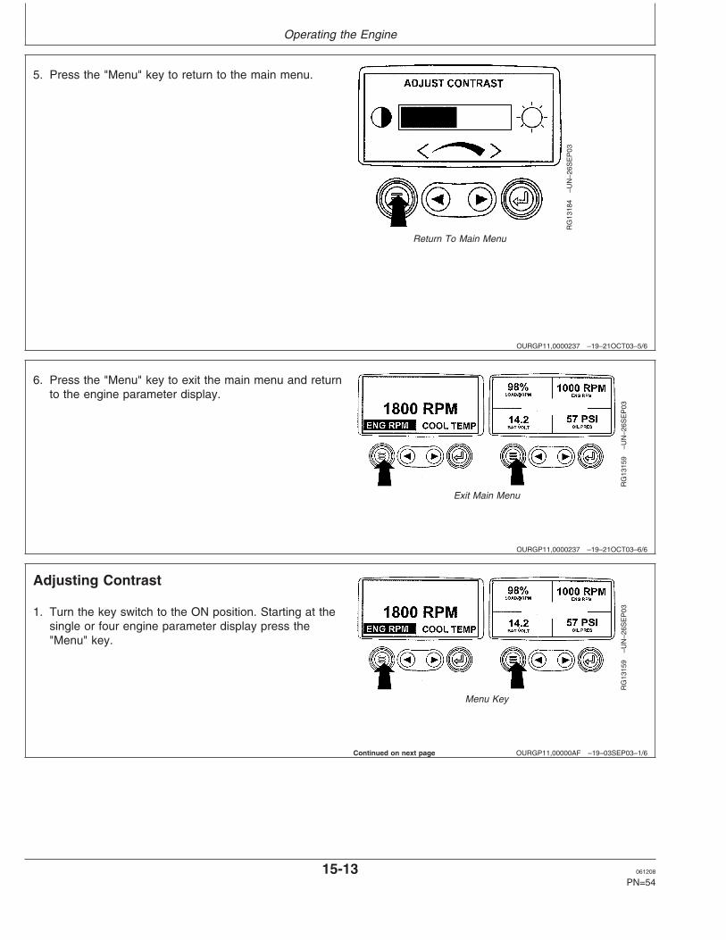
Return To Main Menu
5. Press the "Menu" key to return to the main menu.
OURGP11,0000237 –19–21OCT03–6/6
RG
1315
9–U
N–2
6SE
P03
Exit Main Menu
6. Press the "Menu" key to exit the main menu and returnto the engine parameter display.
OURGP11,00000AF –19–03SEP03–1/6
Adjusting Contrast
RG
1315
9–U
N–2
6SE
P03
Menu Key
1. Turn the key switch to the ON position. Starting at thesingle or four engine parameter display press the"Menu" key.
Continued on next page
15-13 061208
PN=54

Operating the Engine
OURGP11,00000AF –19–03SEP03–2/6
RG
1316
1–U
N–0
2OC
T03
Select Adjust Contrast
2. The main menu will be displayed. Use the "Arrow" keysto scroll through the menu until "Adjust Contrast" ishighlighted.
OURGP11,00000AF –19–03SEP03–3/6
RG
1318
5–U
N–0
2OC
T03
Press Enter Key
3. Once the "Adjust Contrast" menu item has beenhighlighted, press the "Enter" key to activate the"Adjust Contrast" function.
OURGP11,00000AF –19–03SEP03–4/6
RG
1318
6–U
N–2
9SE
P03
Adjust Contrast Intensity
4. Use the "Arrow" keys to select the desired contrastintensity.
15-14 061208
PN=55
Continued on next page

Operating the Engine
OURGP11,00000AF –19–03SEP03–5/6
RG
1318
7–U
N–2
6SE
P03
Return To Main Menu
5. Press the "Menu" key to return to the main menu.
OURGP11,00000AF –19–03SEP03–6/6
RG
1315
9–U
N–2
6SE
P03
Exit Main Menu
6. Press the "Menu" key to exit the main menu and returnto the engine parameter display.
OURGP11,00000B0 –19–03SEP03–1/7
Selecting Units Of Measurement
RG
1315
9–U
N–2
6SE
P03
Menu Key
1. Turn the key switch to the ON position. Starting at thesingle or four engine parameter display, press the"Menu" key.
Continued on next page
15-15 061208
PN=56

Operating the Engine
OURGP11,00000B0 –19–03SEP03–2/7
RG
1318
8–U
N–0
2OC
T03
Select Units
2. The main menu will be displayed. Use the "Arrow" keysto scroll through the menu until "Select Units" ishighlighted.
OURGP11,00000B0 –19–03SEP03–3/7
RG
1318
9–U
N–0
2OC
T03
Press Enter Key
3. Once the "Select Units" menu item has beenhighlighted press the "Enter" key to access the "SelectUnits" function.
OURGP11,00000B0 –19–03SEP03–4/7
RG
1319
0–U
N–2
6SE
P03
Select Desired Units
4. There are three choices for units of measurement,English, Metric kPa or Metric Bar.
English is for Imperial units, with pressures displayedin PSI and temperatures in °F.
Metric kPa and Metric bar are for IS units, withpressures displayed in kPa and bar respectively, andtemperatures in °C.
Use the "Arrow" keys to highlight the desired units ofmeasurement.
15-16 061208
PN=57
Continued on next page

Operating the Engine
OURGP11,00000B0 –19–03SEP03–5/7
RG
1319
1–U
N–3
0SE
P03
Press Enter Key to Select
5. Press the "Enter" key to select the highlighted units.
OURGP11,00000B0 –19–03SEP03–6/7
RG
1319
2–U
N–2
6SE
P03
Return To Main Menu
6. Press the "Menu" key to return to the main menu.
OURGP11,00000B0 –19–03SEP03–7/7
RG
1315
9–U
N–2
6SE
P03
Press Menu Key
7. Press the "Menu" key to return to the engineparameter display.
15-17 061208
PN=58

Operating the Engine
OURGP11,00000B1 –19–03SEP03–1/18
Setup 1-Up Display
RG
1315
9–U
N–2
6SE
P03
Menu Key
1. Turn the key switch to the ON position. Starting at thesingle engine parameter display, press the "Menu" key.
OURGP11,00000B1 –19–03SEP03–2/18
RG
1319
3–U
N–0
2OC
T03
Setup 1-Up Display
2. Use the "Arrow" keys to scroll through the menu until"Setup 1-Up Display" is highlighted.
OURGP11,00000B1 –19–03SEP03–3/18
RG
1319
4–U
N–0
2OC
T03
Press Enter Key
3. Once "Setup 1-Up Display" menu item has beenhighlighted press the "Enter" key to access the "Setup1-Up Display" function.
Continued on next page
15-18 061208
PN=59

Operating the Engine
OURGP11,00000B1 –19–03SEP03–4/18
RG
1319
6–U
N–2
6SE
P03
1-Up Display Options
4. Three options are available for modification of the 1-UpDisplay.
a. Use Defaults – This option contains the followingengine parameters for display: Engine Hours,Engine Speed, Battery Voltage, % Load, CoolantTemperature and Oil Pressure.
b. Custom Setup – This option contains a list ofengine parameters. Engine parameters from this listcan be selected to replace any or all of the defaultparameters. This option can be used to addparameters available for scrolling in the 1-UpDisplay.
c. Automatic Scan – Selecting the scan function willallow the 1-Up Display to scroll through the selectedset of parameters one at a time, momentarilypausing at each.
OURGP11,00000B1 –19–03SEP03–5/18
RG
1319
5–U
N–2
6SE
P03
Select Defaults
5. Use Defaults - To select "Use Defaults" use the Arrowkeys to scroll to and highlight "Use Defaults" in themenu display.
Continued on next page
15-19 061208
PN=60

Operating the Engine
OURGP11,00000B1 –19–03SEP03–6/18
RG
1319
7–U
N–2
9SE
P03
Defaults Selected
6. Press the "Enter" key to activate the "Use Defaults"function.
OURGP11,00000B1 –19–03SEP03–7/18
RG
1314
9–U
N–2
4SE
P03
Restored To Defaults
7. The display parameters are reset to the factorydefaults, then the display will return to the "Setup 1-UpDisplay" menu.
OURGP11,00000B1 –19–03SEP03–8/18
RG
1319
8–U
N–2
6SE
P03
Select Custom Setup
8. Custom Setup - To perform a custom setup of the1-Up Display, use the arrow buttons to scroll to andhighlight "Custom Setup" on the display.
15-20 061208
PN=61
Continued on next page

Operating the Engine
OURGP11,00000B1 –19–03SEP03–9/18
RG
1319
9–U
N–2
6SE
P03
Engine Parameters
9. Press the "Enter" key to display a list of engineparameters.
OURGP11,00000B1 –19–03SEP03–10/18
RG
1315
0–U
N–2
4SE
P03
Select Parameters
10. Use the "Arrow" keys to scroll to and highlight aselected parameter (parameter with a number to rightof it).
OURGP11,00000B1 –19–03SEP03–11/18
RG
1321
9–U
N–2
6SE
P03
Deselect Parameters
11. Press the "Enter" key to deselect the selectedparameter, removing it from the list of parametersbeing displayed on the 1-Up Display.
15-21 061208
PN=62
Continued on next page

Operating the Engine
OURGP11,00000B1 –19–03SEP03–12/18
RG
1315
1–U
N–2
4SE
P03
Select Desired Parameters
12. Use the "Arrow" keys to scroll and highlight thedesired parameter that has not been selected fordisplay (parameter without a number to right of it).
OURGP11,00000B1 –19–03SEP03–13/18
RG
1322
0–U
N–2
6SE
P03
Select Parameters For Display
13. Press the "Enter" key to select the parameter forinclusion in the Single Engine Parameter Display.
14. Continue to scroll through and select additionalparameters for the custom 1-Up Display. Press the"Menu" key at any time to return to the "CustomSetup" menu.
OURGP11,00000B1 –19–03SEP03–14/18
RG
1322
1–U
N–2
6SE
P03
Automatic Scan Off
15. Automatic Scan - Selecting the scan function willallow the 1- Up Display to scroll through the selectedset of parameters one at a time. Use the "Arrow" keysto scroll to the "Automatic Scan" function.
15-22 061208
PN=63
Continued on next page

Operating the Engine
OURGP11,00000B1 –19–03SEP03–15/18
RG
1322
2–U
N–2
6SE
P03
Automatic Scan On
16. Press the "Enter" key to toggle the "Automatic Scan"function on.
OURGP11,00000B1 –19–03SEP03–16/18
RG
1322
3–U
N–2
6SE
P03
Automatic Scan Off
17. Press the "Enter" key again to toggle the "AutomaticScan" function off.
Continued on next page
15-23 061208
PN=64

Operating the Engine
OURGP11,00000B1 –19–03SEP03–17/18
RG
1322
4–U
N–2
6SE
P03
Menu Key
18. Once the "Use Defaults", "Custom Setup" and"Automatic Scan" functions have been set, press the"Menu" key to return to the main menu.
OURGP11,00000B1 –19–03SEP03–18/18
RG
1315
9–U
N–2
6SE
P03
Exit Main Menu
19. Press the "Menu" key to exit the main menu andreturn to the engine parameter display.
OURGP11,00000B2 –19–03SEP03–1/14
Setup 4-Up Display
RG
1315
9–U
N–2
6SE
P03
Menu Key
1. Turn the key switch to the ON position. From the singleor four engine parameter display, press the "Menu"key.
Continued on next page
15-24 061208
PN=65

Operating the Engine
OURGP11,00000B2 –19–03SEP03–2/14
RG
1322
5–U
N–0
2OC
T03
Select Setup 4-Up Display
2. The main menu will be displayed. Use the "Arrow" keysto scroll through the menu until "Setup 4-Up Display" ishighlighted.
OURGP11,00000B2 –19–03SEP03–3/14
RG
1322
6–U
N–0
2OC
T03
Press Enter Key
3. Once the "Setup 4-Up Display" menu item has beenhighlighted, press the "Enter" key to activate the "Setup4-Up Display" menu.
Continued on next page
15-25 061208
PN=66

Operating the Engine
OURGP11,00000B2 –19–03SEP03–4/14
RG
1324
4–U
N–0
2OC
T03
Select Factory Defaults
4. Two options are available for the 4-Up Display.
a. Use Defaults – This option contains the followingengine parameters for display: Engine Speed,Battery Voltage, Coolant Temperature and OilPressure.
b. Custom Setup – This option contains a list ofengine parameters. Engine parameters from this listcan be selected to replace any or all of the defaultparameters.
OURGP11,00000B2 –19–03SEP03–5/14
RG
1314
9–U
N–2
4SE
P03
Restored To Defaults
5. To reset the display parameters to the factory defaults,scroll to and highlight "Use Defaults". Press the "Enter"key to activate the "Use Defaults" function. A messageindicating the display parameters are reset to thefactory defaults will be displayed, then the display willreturn to the "Setup 4-Up Display" menu.
OURGP11,00000B2 –19–03SEP03–6/14
RG
1322
7–U
N–2
6SE
P03
Custom Setup
6. Custom Setup - To perform a custom setup of the4-Up Display, use the arrow buttons to scroll to andhighlight "Custom Setup" on the display.
15-26 061208
PN=67
Continued on next page

Operating the Engine
OURGP11,00000B2 –19–03SEP03–7/14
RG
1322
8–U
N–2
6SE
P03
Select Parameters
7. The quadrant with the highlighted parameter value isthe current selected parameter. Use the "Arrow" keysto highlight the value in the quadrant you wish tochange to a new parameter.
OURGP11,00000B2 –19–03SEP03–8/14
RG
1322
9–U
N–2
6SE
P03
List Of Engine Parameters
8. Press the "Enter" key and a list of engine parameterswill be displayed.
OURGP11,00000B2 –19–03SEP03–9/14
RG
1323
0–U
N–2
6SE
P03
Select Desired Engine Parameter
9. The parameter that is highlighted is the selectedparameter for the screen. Use the "arrow" keys tohighlight the new parameter to be placed in the "4-UpDisplay".
Continued on next page
15-27 061208
PN=68

Operating the Engine
OURGP11,00000B2 –19–03SEP03–10/14
RG
1323
1–U
N–2
6SE
P03
Enter Selected Parameter
10. Press the "Enter" key to change the selectedparameter in the quadrant to the new parameter.
OURGP11,00000B2 –19–03SEP03–11/14
RG
1323
2–U
N–2
6SE
P03
Return To 4-Up Custom Setup
11. Use the "Menu" keys to return to the "4-Up CustomSetup" screen.
OURGP11,00000B2 –19–03SEP03–12/14
RG
1315
3–U
N–2
4SE
P03
4-Up Display
12. The selected quadrant has now changed to the newselected parameter.
Continued on next page
15-28 061208
PN=69
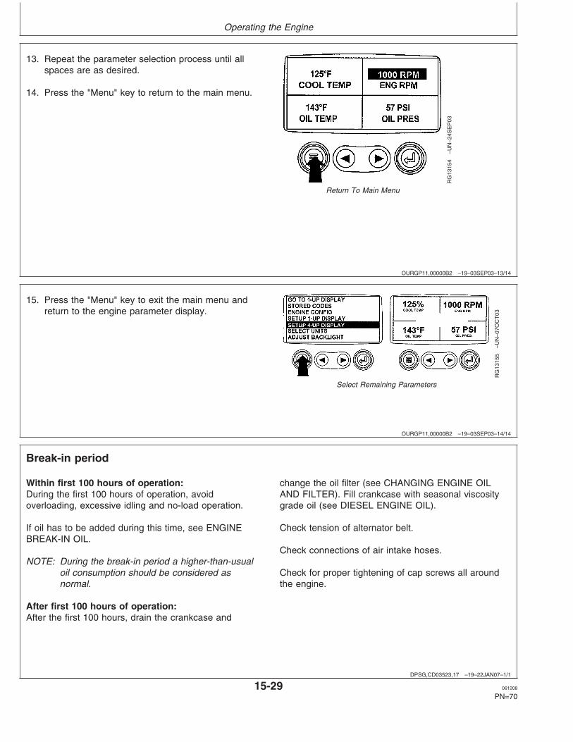
Operating the Engine
OURGP11,00000B2 –19–03SEP03–13/14
RG
1315
4–U
N–2
4SE
P03
Return To Main Menu
13. Repeat the parameter selection process until allspaces are as desired.
14. Press the "Menu" key to return to the main menu.
OURGP11,00000B2 –19–03SEP03–14/14
RG
1315
5–U
N–0
7OC
T03
Select Remaining Parameters
15. Press the "Menu" key to exit the main menu andreturn to the engine parameter display.
DPSG,CD03523,17 –19–22JAN07–1/1
Break-in period
Within first 100 hours of operation:During the first 100 hours of operation, avoidoverloading, excessive idling and no-load operation.
If oil has to be added during this time, see ENGINEBREAK-IN OIL.
NOTE: During the break-in period a higher-than-usualoil consumption should be considered asnormal.
After first 100 hours of operation:After the first 100 hours, drain the crankcase and
change the oil filter (see CHANGING ENGINE OILAND FILTER). Fill crankcase with seasonal viscositygrade oil (see DIESEL ENGINE OIL).
Check tension of alternator belt.
Check connections of air intake hoses.
Check for proper tightening of cap screws all aroundthe engine.
15-29 061208
PN=70
Operating the Engine
DPSG,CD03523,18 –19–22JAN07–1/1
Starting the engine
CAUTION: Before starting engine in aconfined building, install proper outletexhaust ventilation equipment. Always usesafety approved fuel storage and piping.
NOTE: If temperature is below 0 ° C (32 ° F), it maybe necessary to use cold weather starting aids(See COLD WEATHER OPERATION).
1. Perform all prestarting checks outlined inMaintenance/Daily Section.
2. Open the fuel supply shut-off valve, if equipped.
3. Activate the starter motor switch to crank theengine and release it as soon as engine starts.
NOTE: Do not operate the starter motor more than 20seconds at a time.
DPSG,CD03523,19 –19–06FEB07–1/4
Cold weather operation
Depending on equipment, various cold weather startingaids are available to assist in starting the engine attemperature below 0° C (32 °F).
Continued on next page
15-30 061208
PN=71

Operating the Engine
DPSG,CD03523,19 –19–06FEB07–2/4
TS
1356
–UN
–18M
AR
92
Handle starting fluid with care
CD
3075
0–U
N–0
3SE
P99
Glow Plug or Grid-Type air heater
CD
3092
5–U
N–2
3JA
N07
Glow Plugs on HPCR, 4-valve head engine
A—Grid-Type heater (4045 and 6068 non HPCR4-valve head engines)
B—Single Glow Plug (3029 and 4039 engines)C—Multiple Glow Plugs (HPCR 4-valve head engines)
Air intake heater
CAUTION: DO NOT use starting fluid onengines equipped with grid-type air intakeheater or glow plug (s). Ether starting fluid ishighly flammable and may explode, causingserious injury.
NOTE: On engines with electronically controlled fuelsystem (DE10, HPCR), the air intake heateroperates automatically, controlled by the ECU. Anengine preheater indicator light comes on whenthe key switch is turned ON. In warm weather, thelight comes on briefly for a light check. In coldweather, the light remains ON during theautomatic operation of the air intake heater orglow plug (s). Operating time depends ontemperature. Do not crank engine until light goesOFF.
• 3029 and 4039 engines are optionally equipped withthe single glow plug (B) screwed in cylinder head intakemanifold. Activate the glow plug (preheater position) for30 seconds maximum then start the engine.
• 4045 and 6068 engines (except HPCR, 4-valve head)are optionally equipped with the grid-type air heater (A)installed between cylinder head and air intake pipe.- For mechanical fuel system, activate the heatingelement (preheater position) for 30 seconds maximumthen start the engine.- For electronically controlled engines (DE10, HPCR2-valve head), turn key switch ON, but DO NOT crankengine until engine preheater indicator light turns OFF.
• HPCR, 4-valve head engines are equipped with glowplugs (one per cylinder) (C). Turn key switch ON, butDO NOT crank engine until preheater indicator lightturns OFF.
15-31 061208
PN=72
Continued on next page

Operating the Engine
DPSG,CD03523,19 –19–06FEB07–3/4
LX10
1776
8–U
N–2
4OC
T97
Coolant heater
Connect plug of coolant heater (A) to a proper powersource (110 or 220 V).
At an ambient temperature of -15°C (5°F), the heatingprocess takes approximatively 2 hours. Extend heatingperiod if ambient temperature is lower.
DPSG,CD03523,19 –19–06FEB07–4/4
LX10
1770
8–U
N–0
9OC
T97
Fuel preheater
Fuel preheater (A) switches ON and OFF automatically inrelation with the ambient temperature.
15-32 061208
PN=73

Operating the Engine
DPSG,CD03523,20 –19–22JAN07–1/1
Using a booster battery or charger
TS
204
–UN
–23A
UG
88R
G46
78–U
N–1
4DE
C88
12-Volt System
RG
4698
–UN
–14D
EC
88
24-Volts System
A—12-Volt Machine battery (ies)B—12-Volt Booster battery (ies)C—Booster cableD—Cable to starter motor
A 12-volt booster battery can be connected in parallel withbattery(ies) on the unit to aid in cold weather starting.ALWAYS use heavy duty jumper cables.
CAUTION: Gas given off by battery is explosive.Keep sparks and flames away from battery.Before connecting or disconnecting a batterycharger, turn charger off. Make last connectionand first disconnection at a point away frombattery. Always connect NEGATIVE (–) cablelast and disconnect this cable first.
IMPORTANT: Be sure polarity is correct beforemaking connections. Reversed polaritywill damage electrical system. Alwaysconnect positive to positive andnegative to ground. Always use 12-voltbooster battery for 12-volt electricalsystems and 24-volt booster battery(ies)for 24-volt electrical systems.
1. Connect booster battery or batteries to produce therequired system voltage for your engine application.
NOTE: To avoid sparks, DO NOT allow the free ends ofjumper cables to touch the engine.
2. Connect one end of jumper cable to the POSITIVE (+)post of the booster battery.
3. Connect the other end of the jumper cable to thePOSITIVE (+) post of battery connected to starter.
4. Connect one end of the other jumper cable to theNEGATIVE (–) post of the booster battery.
5. ALWAYS complete the hookup by making the lastconnection of the NEGATIVE (–) cable to a goodground on the engine frame and away from thebattery(ies).
6. Start the engine. Disconnect jumper cablesimmediately after engine starts. Disconnect NEGATIVE(–) cable first.
15-33 061208
PN=74

Operating the Engine
DPSG,CD03523,21 –19–22JAN07–1/1
Engine operation
Warming engineOperate engine at high idle for 1 to 2 minutes beforeapplying the load.
NOTE: This procedure does not apply to standbygenerator sets where the engine is loadedimmediately upon reaching rated speed.
Normal engine operationCompare engine coolant temperature and engine oilpressure with specifications below:
SpecificationMinimum oil pressure at fullload rated speed1—Pressure 275 kPa (2.75 bar) (40 psi)...................Coolant temperature range—Temperature 82°—94°C (180°—202°F)...............................................
Stop engine immediately if coolant temperature isabove or oil pressure below specifications or if thereare any signs of part failure. Symptoms that may beearly signs of engine problems could be:
• Sudden loss of power• Unusual noise or vibration• Excessive black exhaust
• Excessive fuel consumption• Excessive oil consumption• Fluid leaks
Recommendation for turbocharger enginesShould the engine stall when operating under load,IMMEDIATELY restart it to prevent overheating ofturbocharger components.
Idling engineAvoid excessive engine idling. Prolonged idling maycause the engine coolant temperature to fall below itsnormal range. This, in turn, causes crankcase oildilution, due to incomplete fuel combustion, andpermits formation of gummy deposits on valves,pistons, and piston rings. It also promotes rapidaccumulation of engine sludge and unburned fuel inthe exhaust system. If an engine will be idling for morethan 5 minutes, stop and restart later.
NOTE: Generator set applications have the governorlocked at a specified speed and do not have aslow idle function. These engines idle at noload governed speed (fast idle).
1Oil at normal operating temperature of 115°C (240°F).
DPSG,CD03523,22 –19–22JAN07–1/1
Standby power units
To assure that your engine will deliver efficient standbyoperation when needed, start engine and run at ratedspeed (with 50%—70% load) for 30 minutes every 2
weeks. DO NOT allow engine to run extended periodof time with no load.
15-34 061208
PN=75

Operating the Engine
DPSG,CD03523,23 –19–22JAN07–1/1
Stopping the engine
1. Before stopping, run engine for at least 2 minutes atfast idle and no load.
2. Stop the engine.
CD03523,000018C –19–26JAN07–1/1
Changing Generator Frequency
Generator sets powered by 6068HFU74 engine aredual-frequency; 50 Hz (1500 rpm) or 60 Hz (1800 rpm).Refer to the generator set documentation for moreinformation.
15-35 061208
PN=76

Maintenance
DPSG,CD03523,24 –19–22JAN07–1/1
Observe service intervals
Using hour meter as a guide, perform all services atthe hourly intervals indicated on following pages. Ateach scheduled maintenance interval, perform allprevious maintenance operations in addition to theones specified. Keep a record of hourly intervals andservices performed using charts provided inMaintenance Records Section.
IMPORTANT: Recommended service intervals arefor normal operating conditions.Service MORE OFTEN if engine isoperated under adverse conditions.Neglecting maintenance can result infailures or permanent damage to theengine.
DPSG,CD03523,25 –19–22JAN07–1/1
Use correct fuels, lubricants and coolant
TS
100
–UN
–23A
UG
88
IMPORTANT: Use only fuels, lubricants, and coolantsmeeting specifications outlined inFuels, Lubricants, and Coolant Sectionwhen servicing your John DeereEngine.
Consult your John Deere engine distributor, servicingdealer or your nearest John Deere Parts Network forrecommended fuels, lubricants, and coolant. Alsoavailable are necessary additives for use when operatingengines in tropical, arctic, or any other adverse conditions.
20-1 061208
PN=77

Maintenance
DPSG,CD03523,26 –19–25JAN07–1/1
Maintenance interval chart
Item 10 H / 500 H 1000 H / 2000 H / 2500 H / Asdaily 1 year 2 years 3 years required
Check engine oil and coolant level •
Check air filter restriction indicatora •
Change engine oil and filterb •
Replace fuel filter element(s) •
Check belt tension and automatic tensionerc • •
Check and adjust valve clearanced • •
Clean crankcase vent tube •
Check air intake hoses, connections and system •
Pressure test cooling system •
Check vibration damper (6 cyl.)e •
Check engine speed and speed drop governor •
Drain and flush cooling systemf • •
Drain water and sediment from fuel filter •
Clean filter element (see note a) •
Test thermostat and injection nozzles (see your dealer)g •
Test glow plugs (HPCR, 4-valve head) •
aClean air filter element when restriction indicator is red. Replace filter element after 6 cleanings or once a year.bChange oil and filter after the first 100 hours of operation, then every 500 hours maximum thereafter (see DIESEL ENGINE OIL information).Change oil and filter at least once a year.cCheck belt tension every 500 hours on 3029 and 4039 engines and on 4045 and 6068 engines with manual tensioner. Check automatic belttensioner every 1000 hours/1 year on 4045 and 6068 engines when equipped.dHave your authorized servicing dealer or engine distributor adjust valve clearance as follows. After the first 500 hours of operation then every1000 hours thereafter on 3029 and 4039 engines. Every 2000 hours on 4045 and 6068 engines.eHave your authorized dealer or engine distributor replace the vibration damper every 4500 hours/5 years.fDrain and flush cooling system every 2500 hours/3 years when John Deere COOL-GARD coolant is used. Otherwise every 2000 hours/2years.gContact your dealer when thermostat or injection nozzles are suspected to be defective. Replace injection nozzles every 5000 hours andthermostat every 10000 hours.
20-2 061208
PN=78

Maintenance/Daily or every 10 hours
DPSG,CD03523,27 –19–07FEB07–1/4
Daily prestarting checks
CD
3075
3–U
N–2
6AU
G99
4045 and 6068 engines
CD
3075
4–U
N–2
6AU
G99
3029 and 4039 engines
CD
3075
5–U
N–2
4SE
P99
FD
0000
47–U
N–1
3MA
R96
Do the following BEFORE STARTING THE ENGINEfor the first time each day:
IMPORTANT: DO NOT add makeup oil until the oillevel is BELOW the add mark.
1. Check engine oil level on dipstick (A). Add asrequired, using seasonal viscosity grade oil. (See
DIESEL ENGINE OIL). Add oil at rocker arm coverfiller cap (B).
IMPORTANT: DO NOT fill above the crosshatcharea. Oil levels anywhere withincrosshatch are considered in theacceptable operating range.
Continued on next page
25-1 061208
PN=79

Maintenance/Daily or every 10 hours
DPSG,CD03523,27 –19–07FEB07–2/4
TS
281
–UN
–23A
UG
88
CD
3075
6–U
N–2
6AU
G99
2.
CAUTION: Explosive release of fluids frompressurized cooling system can causeserious burns.
Only remove filler cap when engine is coldor when cool enough to touch with bare
hands. Slowly loosen cap to first stop torelieve pressure before removing completely.
Remove radiator cap (E) and check coolant levelwhich should be at bottom of filler neck. Fill radiatorwith proper coolant solution if level is low. (SeeDIESEL ENGINE COOLANT). Check entire coolingsystem for leaks.
DPSG,CD03523,27 –19–07FEB07–3/4
RG
4687
–UN
–20D
EC
88C
D30
757
–UN
–26A
UG
99
3. If air filter has a dust unloader valve (C), squeezevalve tip to release any trapped dirt particles.
4. Check air intake restriction indicator (D). Whenindicator is red, air filter needs to be cleaned.
IMPORTANT: Maximum air intake restriction is 6.25kPa (0.06 bar) (1.0 psi) (25 in. H2O). Aclogged air cleaner element will causeexcessive intake restriction and areduced air supply to the engine.
5. Make a thorough inspection of the enginecompartment.
NOTE: Wipe all fittings, caps, and plugs beforeperforming any maintenance to reduce the chanceof system contamination.
25-2 061208
PN=80
Continued on next page

Maintenance/Daily or every 10 hours
DPSG,CD03523,27 –19–07FEB07–4/4
CD
3092
9–U
N–0
7FE
B07
Drain fuel filter(s)
A—Drain plugB—Air bleed plugC—Primary fuel filterD—Final fuel filter
6.
NOTE: Engines with mechanical fuel system have asingle fuel filter while electronically controlledengines (DE10 and HPCR fuel systems) have twofuel filters (primary and final). Moreover theseelectronically controlled engines may be equippedwith a water sensor at the fuel filters. An indicatorlight on the instrument panel will signal theoperator that water should be drained from filterbowls.
Check fuel filters (C) and (D) for water and debris asfollows:
a. Loosen drain plug(s) (A) at bottom of fuel filter(s) orbowl(s) two or three turns.
b. Loosen air bleed plug(s) (B) two full turns and drainwater into a suitable container.
c. When fuel starts to drain out, tighten drain plug(s)securely.
d. Bleed fuel system.
25-3 061208
PN=81
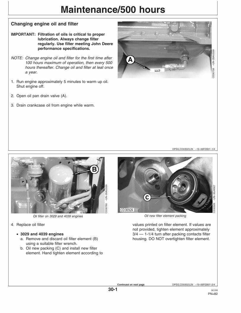
Maintenance/500 hours
DPSG,CD03523,29 –19–06FEB07–1/4
Changing engine oil and filter
CD
3075
8–U
N–2
6AU
G99
IMPORTANT: Filtration of oils is critical to properlubrication. Always change filterregularly. Use filter meeting John Deereperformance specifications.
NOTE: Change engine oil and filter for the first time after100 hours maximum of operation, then every 500hours thereafter. Change oil and filter at leat oncea year.
1. Run engine approximately 5 minutes to warm up oil.Shut engine off.
2. Open oil pan drain valve (A).
3. Drain crankcase oil from engine while warm.
DPSG,CD03523,29 –19–06FEB07–2/4
CD
3076
0–U
N–2
6AU
G99
Oil filter on 3029 and 4039 enginesC
D30
926
–UN
–30J
AN
07Oil new filter element packing
4. Replace oil filter
• 3029 and 4039 enginesa. Remove and discard oil filter element (B)
using a suitable filter wrench.b. Oil new packing (C) and install new filter
element. Hand tighten element according to
values printed on filter element. If values arenot provided, tighten element approximately3/4 — 1-1/4 turn after packing contacts filterhousing. DO NOT overtighten filter element.
30-1 061208
PN=82
Continued on next page

Maintenance/500 hours
DPSG,CD03523,29 –19–06FEB07–3/4
CD
3075
9A–U
N–2
9JA
N07
Oil filter on 4045 and 6068 engines
RG
1161
7–U
N–2
4OC
T01
Oil filter seals
RG
1161
8–U
N–2
4OC
T01
Filter and mounting header
A—Oil filter elementB—Inner sealC—Outer sealD—Sealing surfaceE—Sealing surfaceF—Dust seal
• 4045 and 6068 enginesa. Remove and discard oil filter element (A) using a
suitable filter wrench.b. Apply clean engine oil to inner (B) and outer (C)
seals and to filter threads.c. Wipe both sealing surfaces of the header (D, E)
with a clean rag. Ensure notches in dust seal (F)are properly installed in the slots in the housing.Replace dust seal if damaged.
d. Install and tighten oil filter by hand until firmlyagainst dust seal (F). DO NOT overtighten.
5. Close oil pan drain valve.
Continued on next page
30-2 061208
PN=83
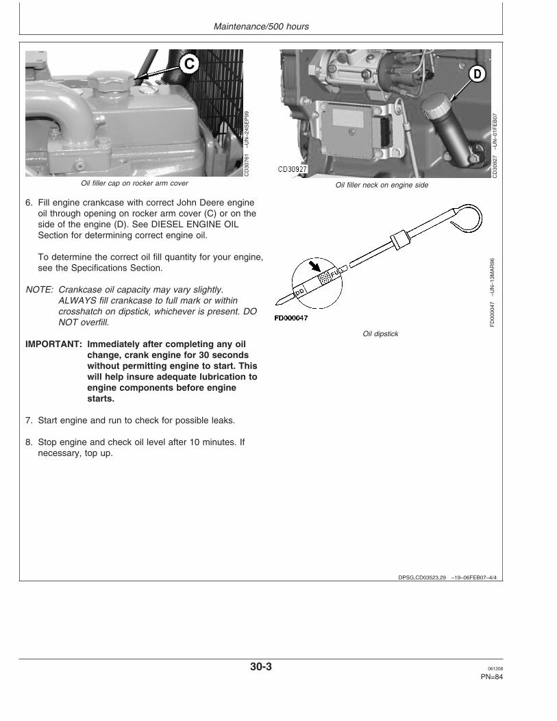
Maintenance/500 hours
DPSG,CD03523,29 –19–06FEB07–4/4
CD
3076
1–U
N–2
4SE
P99
Oil filler cap on rocker arm cover
CD
3092
7–U
N–0
1FE
B07
Oil filler neck on engine side
FD
0000
47–U
N–1
3MA
R96
Oil dipstick
6. Fill engine crankcase with correct John Deere engineoil through opening on rocker arm cover (C) or on theside of the engine (D). See DIESEL ENGINE OILSection for determining correct engine oil.
To determine the correct oil fill quantity for your engine,see the Specifications Section.
NOTE: Crankcase oil capacity may vary slightly.ALWAYS fill crankcase to full mark or withincrosshatch on dipstick, whichever is present. DONOT overfill.
IMPORTANT: Immediately after completing any oilchange, crank engine for 30 secondswithout permitting engine to start. Thiswill help insure adequate lubrication toengine components before enginestarts.
7. Start engine and run to check for possible leaks.
8. Stop engine and check oil level after 10 minutes. Ifnecessary, top up.
30-3 061208
PN=84

Maintenance/500 hours
DPSG,CD03523,30 –19–07FEB07–1/2
Replacing fuel filter element(s)
X98
11–U
N–2
3AU
G88
CD
3093
0–U
N–0
7FE
B07
Fuel filters
A—Retaining ring C—Drain plug E—Water separator bowl F—Primary fuel filter elementB—Final fuel filter element D—Bleed plug
CAUTION: Escaping fluid under pressurecan penetrate the skin causing seriousinjury. Relieve pressure beforedisconnecting fuel or other lines. Tighten allconnections before applying pressure. Keephands and body away from pinholes andnozzles which eject fluids under highpressure. Use a piece of cardboard or paperto search for leaks. Do not use your hand.
If any fluid is injected into the skin, it mustbe surgically removed within a few hours bya doctor familiar with this type injury organgrene may result. Doctors unfamiliar withthis type of injury may call the Deere &Company Medical Department in Moline,Illinois, or other knowledgeable medicalsource.
NOTE: Engines with mechanical fuel system have asingle fuel filter while electronically controlledengines (DE10, HPCR) have two fuel filters(primary and final). Both the primary and thefinal filters have to be replaced together at thesame time.
1. Thoroughly clean fuel filter assembly andsurrounding area.
2. Loosen drain plug (C) and drain fuel into a suitablecontainer.
NOTE: Lifting up on retaining ring as it is rotated helpsto get it past raised locators.
3. Firmly grasp the retaining ring (A) and rotate itclockwise 1/4 turn. Remove ring with filter element(B).
IMPORTANT: Do not dump the old fuel into thenew filter element. This could causefuel injection problem.
A plug is provided with the newelement for plugging the usedelement.
4. Inspect filter mounting base for cleanliness. Cleanas required.
30-4 061208
PN=85
Continued on next page
Maintenance/500 hours
DPSG,CD03523,30 –19–07FEB07–2/2
NOTE: Raised locators on fuel filter canister must beindexed properly with slots in mounting basefor correct installation.
5. Install new filter element dry onto mounting base.Be sure element is properly indexed and firmlyseated on base. It may be necessary to rotate filterfor correct alignment.
6. Install retaining ring onto mounting base makingcertain dust seal is in place on filter base. Hand
tighten ring (about 1/3 turn) until it ”snaps” into thedetent. DO NOT overtighten retaining ring.
NOTE: The proper installation is indicated when a"click" is heard and a release of the retainingring is felt.
7. Bleed the fuel system.
30-5 061208
PN=86

Maintenance/500 hours
DPSG,CD03523,31 –19–30JAN07–1/1
Checking belt (3029 and 4039 Engines)
CD
3064
4–U
N–0
4MA
Y98
CD
3064
5–U
N–0
4MA
Y98
CD
3064
6–U
N–0
4MA
Y98
A—JDG529 Tension GaugeB—Tension testerC—StraightedgeD—Upper nutE—Lower nut
1. Inspect belt for cracks, fraying, or stretched out areas.Replace as necessary.
2. Check belt tension using one of following methods:
a) Use of JDG529 Tension Gauge (A)
SpecificationBelt tension—New belt 578—622 N (130—140 lb-force)...........................Used belt 378—423 N (85—94 lb-force)....................................................
NOTE: Belt is considered used after 10 minutes ofoperation.
b) Use of tension tester (B) and straightedge (C)A 89 N (20 lb) force applied halfway between pulleysshould deflect belt by 19 mm (0.75 in.).
3. If adjustment is necessary, loosen alternator nuts (D)and (E). Pull alternator frame outward until belt iscorrectly tensioned.
IMPORTANT: Do not pry against the alternator rearframe. Do not tighten or loosen beltswhile they are hot.
4. Tighten alternator bracket nuts firmly.
5. Run engine for 10 minutes then recheck belt tension.
30-6 061208
PN=87

Maintenance/500 hours
DPSG,CD03523,57 –19–30JAN07–1/1
Checking belt (4045 and 6068 Engines withmanual tensioner)
RG
9132
–UN
–04O
CT
99
Manual belt tensioner on 4045 and 6068 engines
CD
3084
3–U
N–1
0JA
N03
Reference marks
A—Belt gaugeB—Cap screwC—Cap screwD—Reference markE—Alternator upper bracket notch
Inspect belts for cracks, fraying, or stretched out areas.Replace if necessary.
NOTE: Belt adjustment is measured using a gaugestamped on the top edge of the alternator bracket.
1. Loosen cap screws (B) and (C).
2. Slide alternator in slot by hand to remove all excessslack in belt. Scribe a reference mark (D) on line withnotch (E) on upper alternator bracket.
IMPORTANT: Do not pry against alternator rear frame.
3. Using the gauge (A) on the alternator bracket, stretchbelt by prying outward on alternator front frame.Stretch the belt 1 gauge unit for a used belt and 1.5gauge units for a new belt.
4. Tighten cap screws (B) and (C).
30-7 061208
PN=88
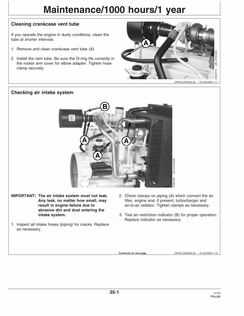
Maintenance/1000 hours/1 year
DPSG,CD03523,32 –19–22JAN07–1/1
Cleaning crankcase vent tube
CD
3077
3–U
N–2
7AU
G99
If you operate the engine in dusty conditions, clean thetube at shorter intervals.
1. Remove and clean crankcase vent tube (A).
2. Install the vent tube. Be sure the O-ring fits correctly inthe rocker arm cover for elbow adapter. Tighten hoseclamp securely.
DPSG,CD03523,33 –19–22JAN07–1/2
Checking air intake system
CD
3076
2–U
N–2
7AU
G99
IMPORTANT: The air intake system must not leak.Any leak, no matter how small, mayresult in engine failure due toabrasive dirt and dust entering theintake system.
1. Inspect all intake hoses (piping) for cracks. Replaceas necessary.
2. Check clamps on piping (A) which connect the airfilter, engine and, if present, turbocharger andair-to-air radiator. Tighten clamps as necessary.
3. Test air restriction indicator (B) for proper operation.Replace indicator as necessary.
Continued on next page
35-1 061208
PN=89

Maintenance/1000 hours/1 year
DPSG,CD03523,33 –19–22JAN07–2/2
RG
4687
–UN
–20D
EC
88
4.
If engine has a rubber dust unloader valve (C), inspectthe valve on bottom of air filter for cracks or plugging.Replace as necessary.
5. Service air filter as necessary.
DPSG,CD03523,34 –19–30JAN07–1/2
Checking automatic belt tensioner (4045 and6068 Engines)
RG
8098
–UN
–18N
OV
97
Earlier design tensioner
RG
1374
4–U
N–1
1NO
V04
Later design tensioner
A—Swing arm stopB—Fixed cast stop
Belt drive systems equipped with automatic (spring) belttensioners cannot be adjusted or repaired. The automaticbelt tensioner is designed to maintain proper belt tensionover the life of the belt. If tensioner spring tension is notwithin specification, replace tensioner assembly.
• Checking belt wearThe belt tensioner is designed to operate within the limitof arm movement provided by the cast stops (A and B)when correct belt length and geometry is used. If thetensioner stop on swing arm (A) is hitting the fixed stop(B), check mounting brackets (alternator, belt tensioner,idler pulley, etc.) and the belt length. Replace belt asneeded (see REPLACING FAN AND ALTERNATORBELTS).
Continued on next page
35-2 061208
PN=90

Maintenance/1000 hours/1 year
DPSG,CD03523,34 –19–30JAN07–2/2
RG
7977
–UN
–14N
OV
97
Marks on tensioner
RG
1205
4–U
N–0
8JA
N02
Align marks
A—Mark on swing armB—Mark on tensioner mounting base
• Checking tensioner spring tensionA belt tension gauge will not give an accurate measureof the belt tension when automatic spring tensioner isused. Measure tensioner spring tension using a torquewrench and procedure outlined below:a. Release tension on belt using a breaker bar and
socket on tension arm. Remove belt from pulleys.b. Release tension on tension arm and remove breaker
bar.c. Put a mark (A) on swing arm of tensioner as shown.d. Measure 21 mm (0.83 in.) from (A) and put a mark
(B) on tensioner mounting base.
NOTE: Earlier engines have a LEFT-HAND thread rollercap screw while later engines have a 12.7 mm(1/2 in.) square hole in tensioner.
e. Install torque wrench on roller cap screw or insquare hole so that it is aligned with center of rollerand tensioner as shown. Rotate the swing arm usinga torque wrench until marks (A and B) are aligned.
f. Record torque wrench measurement and comparewith specification below. Replace tensioner assemblyas required.
SpecificationSpring—Force 18—22 N•m (13—16 lb-ft)...................................................
35-3 061208
PN=91

Maintenance/1000 hours/1 year
DPSG,CD03523,35 –19–31JAN07–1/4
Check and adjust engine valve clearance(3029 and 4039 Engines)
CD
3054
4–U
N–1
9MA
Y98
NOTE: Valve clearance must be adjusted after the first500 hours of operation, then every 1000 hoursthereafter.
Adjust engine valve clearance as follows or have yourauthorized servicing dealer or engine distributor adjust theengine valve clearance.
1. Remove rocker arm cover and crankcase vent tube.
2. Using JDE83 or JDG820 Flywheel Turning Tool (A),rotate engine flywheel in running direction (clockwiseviewed from water pump) until No.1 piston (front) hasreached top dead center (TDC) on compression stroke.Insert timing pin JDE81-4 or JDG1571 (B) into flywheelbore.
DPSG,CD03523,35 –19–31JAN07–2/4
CD
3054
5–U
N–1
9MA
Y98
RG
6307
–UN
–03A
UG
92
3. Check and adjust valve clearance to specificationsaccording to following procedures.
SpecificationValve clearance (engine cold)—Intake 0.35 mm (0.014 in.)..........................................................................Exhaust 0.45 mm (0.018 in.).......................................................................
NOTE: If rocker arm is equipped with adjusting screw andjam nut (A), tighten jam nut to 27 N•m (20 lb-ft)after adjusting valve clearance.
4. Reinstall rocker arm cover and crankcase vent tube.
35-4 061208
PN=92
Continued on next page

Maintenance/1000 hours/1 year
DPSG,CD03523,35 –19–31JAN07–3/4
CD
3054
9–U
N–1
6JU
N98
A—Front of engineB—Exhaust valveC—Intake valveD—No.1 Piston at TDC compression strokeE—No.1 Piston at TDC exhaust stroke
• 3-Cylinder Engine:
NOTE: Firing order is 1-2-3
a. Lock No. 1 piston at TDC compression stroke (D).b. Adjust valve clearance on No. 1 and 2 exhaust
valves and No.1 and 3 intake valves.c. Rotate flywheel 360°. Lock No. 1 piston at TDC
exhaust stroke (E).d. Adjust valve clearance on No. 3 exhaust valve and
No. 2 intake valve.
DPSG,CD03523,35 –19–31JAN07–4/4
RG
4776
–UN
–31O
CT
97
A—Front of engineB—No.1 Piston at TDC compression strokeC—No.4 Piston at TDC compression strokeE—Exhaust valveI—Intake valve
• 4-Cylinder Engine:
NOTE: Firing order is 1-3-4-2
a. Lock No. 1 piston at TDC compression stroke (B).b. Adjust valve clearance on No. 1 and 3 exhaust
valves and No.1 and 2 intake valves.c. Rotate flywheel 360°. Lock No. 4 piston at TDC
compression stroke (C).d. Adjust valve clearance on No. 2 and 4 exhaust
valves and No. 3 and 4 intake valves.
35-5 061208
PN=93

Maintenance/1000 hours/1 year
CD03523,00000EC –19–22JAN07–1/1
Pressure testing cooling system
RG
6557
–UN
–20J
AN
93
Test radiador cap
RG
6558
–UN
–20J
AN
93
Test cooling system
CAUTION: Explosive release of fluids frompressurized cooling system can causeserious burns.
Shut off engines. Only remove filler capwhen cool enough to touch with bare hands.Slowly loosen cap to first stop to relievepressure before removing completely.
Test Radiator Cap
1. Remove radiator cap and attach to D05104STtester as shown.
2. Pressurize cap to specification listed. Gauge shouldhold pressure for 10 seconds within the normalrange if cap is acceptable.
If gauge does not hold pressure, replace radiatorcap.
SpecificationRadiator Cap Calibration—Pressure 70 kPa (0.7 bar) (10 psi) for 10
seconds minimum.............................................
3. Remove the cap from gauge, turn it 180°, andretest cap to confirm measurement.
Test Cooling System
NOTE: Engine should be warmed up to test overallcooling system.
1. Allow engines to cool, then carefully removeradiator cap.
2. Fill radiator with coolant to the normal operatinglevel.
IMPORTANT: DO NOT apply excessive pressure tocooling system, doing so maydamage radiator and hoses.
3. Connect gauge and adapter to radiator filler neck.Pressurize cooling system to specification listed forradiator cap.
4. With pressure applied, check all cooling systemhose connections, radiator, and overall engine forleaks.
If leakage is detected, correct as necessary andpressure test system again.
If no leakage is detected, but the gauge indicated adrop in pressure, coolant may be leaking internallywithin the system or at the block-to-head gasket.Have your engine distributor or servicing dealercorrect this problem immediately.
35-6 061208
PN=94

Maintenance/2000 hours/2 years
DPSG,CD03523,36 –19–31JAN07–1/4
Check and adjust engine valve clearance(4045 and 6068 Engines)
CD
3054
4–U
N–1
9MA
Y98
Adjust engine valve clearance as follows or have yourauthorized servicing dealer or engine distributor adjust theengine valve clearance.
1. Remove rocker arm cover and crankcase vent tube.
2. Using JDE83 or JDG820 Flywheel Turning Tool (A),rotate engine flywheel in running direction (clockwiseviewed from water pump) until No.1 piston (front) hasreached top dead center (TDC) on compression stroke.Insert timing pin JDE81-4 (B) into flywheel bore.
DPSG,CD03523,36 –19–31JAN07–2/4
RG
7409
–UN
–06A
UG
96
3. Check and adjust valve clearance to specificationsaccording to following procedures.
SpecificationValve clearance (engine cold)—Intake 0.35 mm (0.014 in.)..........................................................................Exhaust 0.45 mm (0.018 in.).......................................................................
4. If valves need adjusting, loosen the locknut on rockerarm adjusting screw. Turn adjusting screw until feelergauge slips with a slight drag. Hold the adjusting screwfrom turning with screwdriver and tighten locknut to 27N•m (20 lb-ft). Recheck clearance after tighteninglocknut. Readjust clearance as necessary
5. Reinstall rocker arm cover and crankcase vent tube.
Continued on next page
40-1 061208
PN=95

Maintenance/2000 hours/2 years
DPSG,CD03523,36 –19–31JAN07–3/4
RG
4776
–UN
–31O
CT
97
A—Front of engineB—No.1 Piston at TDC compression strokeC—No.4 Piston at TDC compression strokeE—Exhaust valveI—Intake valve
• 4-Cylinder Engine:
NOTE: Firing order is 1-3-4-2
a. Lock No. 1 piston at TDC compression stroke (B).b. Adjust valve clearance on No. 1 and 3 exhaust
valves and No.1 and 2 intake valves.c. Rotate flywheel 360°. Lock No. 4 piston at TDC
compression stroke (C).d. Adjust valve clearance on No. 2 and 4 exhaust
valves and No. 3 and 4 intake valves.
DPSG,CD03523,36 –19–31JAN07–4/4
RG
4777
–UN
–31O
CT
97
A—Front of engineB—No.1 Piston at TDC compression strokeC—No.6 Piston at TDC compression strokeE—Exhaust valveI—Intake valve
• 6-Cylinder Engine:
NOTE: Firing order is 1-5-3-6-2-4.
a. Lock No. 1 piston at TDC compression stroke (B).b. Adjust valve clearance on No. 1, 3, and 5 exhaust
valves and No. 1, 2, and 4 intake valves.c. Rotate flywheel 360°. Lock No. 6 piston at TDC
compression stroke (C).d. Adjust valve clearance on No. 2, 4, and 6 exhaust
valves and No. 3, 5, and 6 intake valves.
40-2 061208
PN=96

Maintenance/2000 hours/2 years
DPSG,CD03523,38 –19–31JAN07–1/1
Checking engine speed (Mechanical fuelsystem)
CD
3076
3–U
N–2
4SE
P99
A—Fast idle adjusting screw
NOTE: Most engines for generator set application (1500rpm for 50 Hz or 1800 rpm for 60 Hz) run only atfast idle and therefore they do not have slow idle.
SpecificationFast idle—50 Hz Generator set 1550—1580 rpm......................................60 Hz Generator set 1865—1890 rpm........................................................
NOTE: Fast idle is settled by the factory then the idleadjusting screw (A) is sealed to prevent fromtampering. Fast idle adjustment can only be doneby an authorized fuel system agent.
DPSG,CD03523,39 –19–31JAN07–1/1
Adjust speed droop governor (Mechanicalfuel system)
CD
3076
4–U
N–2
4SE
P99
B—Speed droop governor adjusting screw
1. Warm engine to normal operating temperature.
2. Run engine at fast idle.
3. Apply full load.
4. If specified power cannot be obtained, turn screw (B)to adjust droop until the requested power is reached.
NOTE: If surging exits upon removing the load, turnscrew (B) clockwise to eliminate.
40-3 061208
PN=97

Maintenance/2000 hours/2 years
DPSG,CD03523,40 –19–22JAN07–1/1
Checking crankshaft vibration damper(6-CYLINDER ENGINE ONLY)
RG
8018
–UN
–15J
AN
99R
G75
08–U
N–2
3NO
V97
1. Remove belts (shown removed).
2. Grasp vibration damper with both hands and attempt toturn it in both directions. If rotation is felt, damper isdefective and should be replaced.
IMPORTANT: The vibration damper assembly is notrepairable and should be replaced every4500 hours or 5 years, whicheveroccurs first.
3. Check vibration damper radial runout by positioning adial indicator so probe contacts damper outercircumference.
4. With engine at operating temperature, rotate crankshaftusing JDG820 or JDE83 Flywheel Turning Tool.
5. Note dial indicator reading. If runout exceedsspecifications given below, replace vibration damper.
SpecificationDamper—Maximum radial runout 1.50 mm (0.060 in.)..............................
40-4 061208
PN=98

Maintenance/2500 hours/3 years
DPSG,CD03523,41 –19–06JUN08–1/3
Drain and flush cooling system
TS
281
–UN
–23A
UG
88R
G48
94–U
N–1
4DE
C88
ZX
0161
92–U
N–1
1JA
N99
CD
3076
5–U
N–2
7AU
G99
NOTE: Drain and flush cooling system every 2500hours/3 years when John Deere COOL-GARDcoolant is used. Otherwise every 2000 hours/2years
CAUTION: Explosive release of fluids frompressurized cooling system can cause seriousburns.
Shut off engine. Only remove filler cap whencool enough to touch with bare hands. Slowlyloosen cap to first stop to relieve pressurebefore removing completely.
1. Slowly open the radiator cap.
2. Remove engine block drain plug (A).
3. On POWERTech engines, remove oil cooler housingdrain plug (B).
4. Open radiator drain valve (C). Drain all coolant fromradiator.
5. Close all drain orifices after coolant has drained.
6. Fill the cooling system with clean water. Run engineuntil water passes through the thermostat to stir uppossible rust or sediment.
7. Stop engine and immediately drain the water fromsystem before rust and sediment settle.
8. After draining water, close all drain orifices and fill thecooling system with cleaning product such asPMCC2610 or PMCC2638 Cooling System Cleanersavailable from your John Deere Dealer. Followmanufacturer’s directions on label.
9. After cleaning the cooling system, drain cleaner and fillwith water to flush the system. Run engine until waterpasses through the thermostat, then drain out flushingwater.
45-1 061208
PN=99
Continued on next page

Maintenance/2500 hours/3 years
DPSG,CD03523,41 –19–06JUN08–2/3
10. Check cooling system hoses for proper condition.Replace as necessary.
11. Close all drain orifices and fill the cooling system withspecified coolant (see DIESEL ENGINE COOLANT).
SpecificationCooling system capacity—CD3029DF128 14.5 L (15.5 qt)...................................................................CD3029TF158 14.5 L (15.5 qt)...................................................................CD3029HFS70 14.5 L (15.5 qt)..................................................................CD3029TFS70 14.5 L (15.5 qt)...................................................................CD3029HFU70 14.5 L (15.5 qt)..................................................................CD3029TFU70 14.5 L (15.5 qt)...................................................................CD4039DF008 16.5 L (17.5 qt)...................................................................CD4039TF008 16.5 L (17.5 qt)...................................................................CD4045DF158 20 L (21 qt).........................................................................CD4045HF158 28 L (29.5 qt)......................................................................CD4045TF158 25 L (26.5 qt)......................................................................CD4045TF258 25 L (26.5 qt)......................................................................CD4045HFS72 28 L (29.5 qt).....................................................................CD4045HFS73 32 L (34 qt)........................................................................CD4045HFS80 25 L (26.5 qt).....................................................................CD4045HFS82 32 L (34 qt)........................................................................CD4045HFS83 32 L (34 qt)........................................................................CD4045HFU72 28 L (29.5 qt).....................................................................CD4045HFU79 32 L (34 qt)........................................................................CD4045TFU70 25 L (26.5 qt)......................................................................CD6068HF158 32 L (34 qt).........................................................................CD6068HF258 32 L (34 qt).........................................................................CD6068TF158 28 L (29.5 qt)......................................................................CD6068TF258 28 L (29.5 qt)......................................................................CD6068HFS72 32 L (34 qt)........................................................................CD6068HFS73 32 L (34 qt)........................................................................CD6068HFS76 35 L (37 qt)........................................................................CD6068HFS77 35 L (37 qt)........................................................................CD6068HFS82 32 L (34 qt)........................................................................CD6068HFS83 32 L (34 qt)........................................................................CD6068HFS89 35 L (37 qt)........................................................................CD6068HFU72 32 L (34 qt)........................................................................CD6068HFU74 35 L (37 qt)........................................................................CD6068HFU79 32 L (34 qt)........................................................................
Continued on next page
45-2 061208
PN=100

Maintenance/2500 hours/3 years
DPSG,CD03523,41 –19–06JUN08–3/3
CD
3064
3–U
N–0
4MA
Y98
12. When refilling cooling system, loosen temperaturesensor (B) or plug at the rear of cylinder head toallow air to escape.
13. Run engine until it reaches operating temperaturethen check coolant level and entire cooling system forleaks.
45-3 061208
PN=101

Maintenance/As required
DPSG,CD03523,42 –19–31JAN07–1/1
Additional service information
RG
4624
–UN
–15D
EC
88
This manual does not allow a complete repair of yourengine. If you want want more detailed service informationthe following publications are available from your regularparts channel.
• PC2451 — Parts Catalog for Non-Emission Certifiedengines
• PC3235 — Parts Catalog for Stage II Emission Certifiedengines
• CTM3274 — Component Technical Manual for 3029and 4039 engines (English)
• CTM104 — Component Technical Manual for 4045 and6068 base engines (English)
• CTM207 — Component Technical Manual forMechanical Fuel Systems on 4045 and 6068 engines(English)
• CTM320 — Component Technical Manual for HPCRFuel System on 4045 and 6068 with 4-Valve HeadEngines (English)
• CTM331 — Component Technical Manual for DE10Fuel Systems on 4045 and 6068 engines (English)
• CTM502 — Component Technical Manual for HPCRFuel System on 4045 and 6068 with 2-Valve HeadEngines (English)
• CTM67 — Component Technical Manual for OEMEngine accessories (English only)
• CTM77 — Component Technical Manual for Alternatorsand Starter Motors (English only)
50-1 061208
PN=102

Maintenance/As required
DPSG,CD03523,43 –19–22JAN07–1/1
Do not modify fuel system
CD
3076
8–U
N–2
4SE
P99
IMPORTANT: Modification or alteration of theinjection pump, the injection pumptiming, or the fuel injectors in ways notrecommended by the manufacturer willterminate the warranty obligation to thepurchaser.
Do not attempt to service injectionpump or fuel injectors yourself. Specialtraining and special tools are required.(See your authorized servicing dealer orengine distributor.)
50-2 061208
PN=103

Maintenance/As required
DPSG,CD03523,44 –19–22JAN07–1/1
Clean or replace air filter (one-piece)
CD
3076
6–U
N–0
6SE
P99
RG
9912
–UN
–25F
EB
99
Clean air filter when restriction indicator (A) is red. Airfilter can be cleaned up to six times. Thereafter, or atleast once a year, it must be replaced.
Proceed as follows:
1. Thoroughly clean all dirt around air filter area.
2. Loosen clamp (B) then remove air filter.
IMPORTANT: Never reinstall an air filter which showsevidence of bad condition (punched,dented...) allowing no filtered air toenter the engine.
3. Clean air filter with compressed air working from”clean” to ”dirty” side.
NOTE: Compressed air pressure must not exceed 600kPa (6 bar; 88 psi).
4. Mark air filter to keep track of each cleaning operation.
5. Fully depress air restriction indicator reset button andrelease to reset indicator.
6. Check air system entirely for proper condition (seeCHECKING AIR INTAKE SYSTEM).
50-3 061208
PN=104

Maintenance/As required
DPSG,CD03523,58 –19–22JAN07–1/1
Clean or replace air filter element
CD
3077
2–U
N–2
7AU
G99
A—Primary element B—Secondary (safety) element C—Air restriction indicator D—Wing nut
Clean air filter when restriction indicator (C) is red.Replace both primary (A) and secondary (B) filterelements after primary element has been cleaned sixtimes or at least once a year.
Proceed as follows:
1. Thoroughly clean all dirt around air filter area.
2. Remove wing nut (D) and remove primary element(A) from canister.
IMPORTANT: Do not attempt to clean thesecondary (safety) element (B). Itmust be only replaced asrecommended.
3. Thoroughly clean all dirt from inside canister.
IMPORTANT: If primary element shows evidenceof bad condition (punched,
dented...), replace both the primaryand the secondary elements.
4. Clean primary element with compressed air workingfrom ”clean” to ”dirty” side.
NOTE: Compressed air pressure must not exceed 600kPa (6 bar; 88 psi).
5. Mark air filter to keep track of each cleaningoperation.
6. Fully depress air restriction indicator reset buttonand release to reset indicator.
7. Check air system entirely for proper condition (seeCHECKING AIR INTAKE SYSTEM).
50-4 061208
PN=105

Maintenance/As required
DPSG,CD03523,45 –19–31JAN07–1/1
Replacing fan and alternator belt (4045 and6068 Engines)
CD
3076
9–U
N–0
1SE
P99
Installation on 4045 engines
CD
3077
0–U
N–0
1SE
P99
Installation on 6068 engines
ALT—AlternatorCP—Crank PulleyFD—Fan DriveI—Idler PulleyT—TensionerWP—Water Pump
NOTE: Refer to CHECKING BELT TENSIONER SPRINGTENSION AND BELT WEAR for additionalinformation on the belt tensioner.
1. Inspect belts for cracks, fraying, or stretched out areas.Replace if necessary.
2. On engines with automatic belt tensioner, releasetension on belt using a breaker bar and socket ontension arm.
On engines with manual tensioner, loosen cap screwsholding the alternator.
3. Remove poly V-belt from pulleys and discard belt.
4. Install new belt, making sure belt is correctly seated inall pulley grooves. Refer to belt routing at right for yourapplication.
5. Apply tension to belt (See CHECKING BELT).
6. Start engine and check belt alignment.
50-5 061208
PN=106

Maintenance/As required
DPSG,CD03523,46 –19–09FEB07–1/4
Bleeding the fuel system
X98
11–U
N–2
3AU
G88
RG
7947
–UN
–13N
OV
97
Fuel filter bleed screw
RG
8013
A–U
N–1
5JA
N99
Fuel pump primer lever
CAUTION: Escaping fluid under pressure canpenetrate the skin causing serious injury.Relieve pressure before disconnecting fuel orother lines. Tighten all connections beforeapplying pressure. Keep hands and body awayfrom pinholes and nozzles which eject fluidsunder high pressure. Use a piece of cardboardor paper to search for leaks. Do not use yourhand.
If ANY fluid is injected into the skin, it must besurgically removed within a few hours by adoctor familiar with this type injury or gangrenemay result. Doctors unfamiliar with this type ofinjury may call the Deere & Company MedicalDepartment in Moline, Illinois, or otherknowledgeable medical source.
NOTE: Engines with mechanical fuel system have asingle fuel filter while electronically controlledengines (DE10 and HPCR fuel systems) have twofuel filters (primary and final). Whenever the fuelsystem has been opened up for service (linesdisconnected or filters removed), it will benecessary to bleed air from the system. On dualfuel filter system, bleed air only from final filter.
A.) Mechanical and DE10 fuel systems
1. Loosen the air bleed screw (A) two full turns. On DE10fuel system, loosen only air bleed screw on final fuelfilter.
2. Operate supply pump primer lever (B) until fuel flow isfree from air bubbles.
3. Tighten bleed screw securely, continue operating handprimer until pumping action is not felt.
4. Start engine and check for leaks.
If engine does not start, it will be necessary to bleed airfrom fuel system at fuel injection pump or injectionnozzles as explained next.
50-6 061208
PN=107
Continued on next page

Maintenance/As required
DPSG,CD03523,46 –19–09FEB07–2/4
CD
3077
1–U
N–2
4SE
P99
Mechanical injection pump return line
CD
3092
8–U
N–0
2FE
B07
DE10 Fuel return line
• At Fuel Injection Pump:a. Slightly loosen fuel return line connector (C) at
fuel injection pump.b. Operate fuel supply pump primer lever until fuel,
without air bubbles, flows from fuel return lineconnection.
c. Securely tighten return line connector.
DPSG,CD03523,46 –19–09FEB07–3/4
RG
7725
–UN
–08J
AN
97
Bleed fuel system at fuel injection nozzles
• At Fuel Injection Nozzles:a. Using two open-end wrenches, loosen fuel line
connection at injection nozzle.b. Crank engine over with starting motor, (but do not
start engine), until fuel free from bubbles flows out ofloosened connection. Retighten connection to 27N•m (20 lb-ft).
c. Repeat procedure for remaining injection nozzles (ifnecessary) until all air has been removed from fuelsystem.
If engine still will not start, see your authorized servicingdealer or engine distributor.
Continued on next page
50-7 061208
PN=108
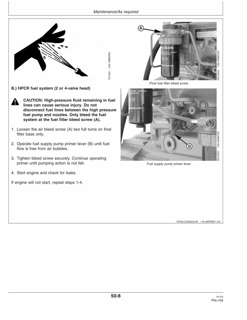
Maintenance/As required
DPSG,CD03523,46 –19–09FEB07–4/4
TS
1343
–UN
–18M
AR
92
RG
1222
0–U
N–2
4MA
Y02
Final fuel filter bleed screw
RG
1222
1–U
N–2
4MA
Y02
Fuel supply pump primer lever
B.) HPCR fuel system (2 or 4-valve head)
CAUTION: High-pressure fluid remaining in fuellines can cause serious injury. Do notdisconnect fuel lines between the high pressurefuel pump and nozzles. Only bleed the fuelsystem at the fuel filter bleed screw (A).
1. Loosen the air bleed screw (A) two full turns on finalfilter base only.
2. Operate fuel supply pump primer lever (B) until fuelflow is free from air bubbles.
3. Tighten bleed screw securely. Continue operatingprimer until pumping action is not felt.
4. Start engine and check for leaks.
If engine will not start, repeat steps 1-4.
50-8 061208
PN=109

Troubleshooting
CD03523,000018D –19–08FEB07–1/1
General troubleshooting information
Troubleshooting electronically controlled engineproblems can be difficult. The first thing to do is toidentify the type of problem which can be mechanicalor electrical.
An engine wiring layout is provided in this section toidentify electrical components (engine controller,sensors, connectors... ).
Later in this section is a list of possible engineproblems and diagnostic trouble codes that may beencountered accompanied by possible causes andcorrections. This troubleshooting information is of ageneral nature. See also the generator documentationfor a complete information of your application.
A reliable program for troubleshooting engine problemsshould include the following basic diagnostic thoughtprocess:
• Know the engine and all related systems.• Study the problem thoroughly.• Relate the symptoms to your knowledge of engine
and systems.• Diagnose the problem starting with the easiest
things first.• Double-check before beginning the disassembly.• Determine cause and make a thorough repair.• After making repairs, operate the engine under
normal conditions to verify that the problem andcause was corrected.
55-1 061208
PN=110

Troubleshooting
CD03523,000018E –19–02FEB07–1/1
Engine Wiring Layout (Electronic Fuel System With Stanadyne DE10 Injection Pump)
RG
1220
1–U
N–2
4MA
Y02
A—Coolant Temperature H—Oil Pressure Sensor N—CAN Network Diagnostic R—Engine Wiring HarnessSensor Connector Connector Connector S—Fuel Heater Connector
B—Fuel Temperature Sensor I—Main System Fuse (10 amp) O—Instrument Panel T—Manifold Air TemperatureConnector J—Power and Ground Battery Connector Harness (MAT) Sensor Connector
C—Injection Pump Solenoid Connections P—23-pin Optional Feature U—Alternator IgnitionConnector K—Fuse Holder Connector Connector
D—SAE 1939 CAN Connector L—Transient Voltage (Extended-feature ECU V—Optional Instrument PanelE—Crankshaft Position Sensor Protection (TVP) Module only) or Generator Instrument
Connector Connector Q—21-pin Instrument Panel PanelF—ECU Connector M—Remote ON/ OFF ConnectorG—Starter Relay Connector Connector
55-2 061208
PN=111

Troubleshooting
CD03523,000018F –19–02FEB07–1/1
Engine Wiring Layout (Electronic Fuel System With Denso High Pressure Common Rail)
RG
1222
4–U
N–1
9JU
N02
6068HFU74 Engine shown
A—Engine Coolant D—ECU Connector G—Engine Oil Pressure J—Crankshaft Position SensorTemperature (ECT) Sensor E—Optional Instrument Panel Sensor Connector K—Pump Position Sensor
B—Electronic Injector or Generator Instrument H—Power and Ground Battery L—Pump Control ValveConnector Panel Connections Solenoid
C—Manifold Air Temperature F—Engine Wiring Harness I—Fuel Rail Pressure Sensor M—Fuel Temperature Sensor(MAT) Sensor
55-3 061208
PN=112

Troubleshooting
DPSG,CD03523,49 –19–22JAN07–1/5
Engine troubleshooting
Symptom Problem Solution
Engine cranks but will not start Incorrect starting procedure. Verify correct starting procedure.
No fuel. Check fuel in tank and manualshut-off valve.
Exhaust restricted. Check and correct exhaustrestriction.
Fuel filter plugged or full of water. Replace fuel filter or drain waterfrom filter.
Injection pump not getting fuel or air Check fuel flow at supply pump orin fuel system. bleed fuel system.
Faulty injection pump or nozzles. Consult authorized diesel repairstation for repair or replacement.
Engine hard to start or will not Engine starting under load. Remove load.start
Improper starting procedure. Review starting procedure.
No fuel. Check fuel tank.
Air in fuel line. Bleed fuel line.
Cold weather. Use cold weather starting aids.
Slow starter speed. See ”Starter Cranks Slowly”.
Crankcase oil too heavy. Use oil of proper viscosity.
Improper type of fuel. Consult fuel supplier; use propertype fuel for operating conditions.
Water, dirt, or air in fuel system. Drain, flush, fill, and bleed system.
Clogged fuel filter. Replace filter element.
Dirty or faulty injection nozzles. Have authorized servicing dealer orengine distributor check injectors.
Injection pump shut-off not reset. Turn key switch to ”OFF” then to”ON”.
55-4 061208
PN=113
Continued on next page

Troubleshooting
DPSG,CD03523,49 –19–22JAN07–2/5
Symptom Problem Solution
Engine knocks Low engine oil level. Add oil to engine crankcase.
Injection pump out of time. See your authorized servicing dealeror engine distributor.
Low coolant temperature. Remove and check thermostat.
Engine overheating. See ”Engine Overheats”.
Engine runs irregularly or stalls Low coolant temperature. Remove and check thermostat.frequently
Clogged fuel filter. Replace fuel filter element.
Water, dirt, or air in fuel system. Drain, flush, fill, and bleed system.
Dirty or faulty injection nozzles. Have authorized servicing dealer orengine distributor check injectors.
Below normal engine Defective thermostat. Remove and check thermostat.temperature
Defective temperature gauge or Check gauge, sender, andsender. connections.
Continued on next page
55-5 061208
PN=114
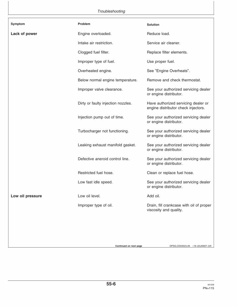
Troubleshooting
DPSG,CD03523,49 –19–22JAN07–3/5
Symptom Problem Solution
Lack of power Engine overloaded. Reduce load.
Intake air restriction. Service air cleaner.
Clogged fuel filter. Replace filter elements.
Improper type of fuel. Use proper fuel.
Overheated engine. See ”Engine Overheats”.
Below normal engine temperature. Remove and check thermostat.
Improper valve clearance. See your authorized servicing dealeror engine distributor.
Dirty or faulty injection nozzles. Have authorized servicing dealer orengine distributor check injectors.
Injection pump out of time. See your authorized servicing dealeror engine distributor.
Turbocharger not functioning. See your authorized servicing dealeror engine distributor.
Leaking exhaust manifold gasket. See your authorized servicing dealeror engine distributor.
Defective aneroid control line. See your authorized servicing dealeror engine distributor.
Restricted fuel hose. Clean or replace fuel hose.
Low fast idle speed. See your authorized servicing dealeror engine distributor.
Low oil pressure Low oil level. Add oil.
Improper type of oil. Drain, fill crankcase with oil of properviscosity and quality.
Continued on next page
55-6 061208
PN=115

Troubleshooting
DPSG,CD03523,49 –19–22JAN07–4/5
Symptom Problem Solution
High oil consumption Crankcase oil too light. Use proper viscosity oil.
Oil leaks. Check for leaks in lines, gaskets,and drain plug.
Restricted crankcase vent tube. Clean vent tube.
Defective turbocharger. See your authorized servicing dealeror engine distributor.
Engine emits white smoke Improper type of fuel. Use proper fuel.
Low engine temperature. Warm up engine to normal operatingtemperature.
Defective thermostat. Remove and check thermostat.
Defective injection nozzles. See your authorized servicing dealeror engine distributor.
Engine out of time. See your authorized servicing dealeror engine distributor.
Engine emits black or gray Improper type of fuel. Use proper fuel.exhaust smoke
Clogged or dirty air cleaner. Service air cleaner.
Engine overloaded. Reduce load.
Injection nozzles dirty. See your authorized servicing dealeror engine distributor.
Engine out of time. See your authorized servicing dealeror engine distributor.
Turbocharger not functioning. See your authorized servicing dealeror engine distributor.
Continued on next page
55-7 061208
PN=116

Troubleshooting
DPSG,CD03523,49 –19–22JAN07–5/5
Symptom Problem Solution
Engine overheats Engine overloaded. Reduce load.
Low coolant level. Fill radiator to proper level, checkradiator and hoses for looseconnections or leaks.
Faulty radiator cap. Have serviceman check.
Stretched poly V-belt or defective Check automatic belt tensioner andbelt tensioner. check belts for stretching. Replace
as required.
Low engine oil level. Check oil level. Add oil as required.
Cooling system needs flushing. Flush cooling system.
Defective thermostat. Remove and check thermostat.
Defective temperature gauge or Check water temperature withsender. thermometer and replace, if
necessary.
Incorrect grade of fuel. Use correct grade of fuel.
High fuel consumption Improper type of fuel. Use proper type of fuel.
Clogged or dirty air cleaner. Service air cleaner.
Engine overloaded. Reduce load.
Improper valve clearance. See your authorized servicing dealeror engine distributor.
Injection nozzles dirty. See your authorized servicing dealeror engine distributor.
Engine out of time. See your authorized servicing dealeror engine distributor.
Defective turbocharger. See your authorized servicing dealeror engine distributor.
Low engine temperature. Check thermostat.
55-8 061208
PN=117

Troubleshooting
DPSG,CD03523,50 –19–22JAN07–1/2
Electrical troubleshooting
Symptom Problem Solution
Undercharged system Excessive electrical load from added Remove accessories or install higheraccessories. output alternator.
Excessive engine idling. Increase engine rpm when heavyelectrical load is used.
Poor electrical connections on Inspect and clean as necessary.battery, ground strap, starter, oralternator.
Defective battery. Test battery.
Defective alternator. Test charging system.
Battery uses too much water Cracked battery case. Check for moisture and replace asnecessary.
Defective battery. Test battery.
Battery charging rate too high. Test charging system.
Batteries will not charge Loose or corroded connections. Clean and tighten connections.
Sulfated or worn-out batteries. See your authorized servicing dealeror engine distributor.
Stretched poly V-belt or defective Adjust belt tension or replace belts.belt tensioner.
Starter will not crank Engine under load Remove load
Loose or corroded connections. Clean and tighten loose connections.
Low battery output voltage. See your authorized servicing dealeror engine distributor.
Faulty start circuit relay. See your authorized servicing dealeror engine distributor.
Blown fuse. Replace fuse.
55-9 061208
PN=118
Continued on next page

Troubleshooting
DPSG,CD03523,50 –19–22JAN07–2/2
Symptom Problem Solution
Starter cranks slowly Low battery output. See your authorized servicing dealeror engine distributor.
Crankcase oil too heavy. Use proper viscosity oil.
Loose or corroded connections. Clean and tighten loose connections.
Entire electrical system Faulty battery connection. Clean and tighten connections.
Sulfated or worn-out batteries. See your authorized servicing dealeror engine distributor.
Blown fuse. Replace fuse.
CD03523,0000190 –19–02FEB07–1/1
Displaying Of Diagnostic Trouble Codes (DTCs)
There are several different methods for displaying bothstored and active DTCs from the ECU via a fault lampor a diagnostic gauge on the electronic instrumentpanel.
2-DIGIT CODES
Some engines display Service Codes or DTCs as2-digit codes read from a fault lamp which gives blinkcodes.
SPN/FMI CODES
Stored and active diagnostic trouble codes are outputon the diagnostic gauge on the Deere electronicinstrument panel according to the J1939 standard as atwo-part code as shown on the tables on the followingpages.
The first part is a six-digit Suspect Parameter Number(SPN) followed by a two-digit Failure Mode Identifier(FMI) code. In order to determine the exact failure,both parts (SPN and FMI) of the code are needed.
The SPN identifies the system or the component thathas the failure; for example SPN 000110 indicates afailure in the engine coolant temperature circuit.
The FMI identifies the type of failure that has occurred;for example FMI 03 indicates value above normal.Combining SPN 000110 with FMI 03 yields enginecoolant temperature input voltage too high, or theequivalent of 2-digit fault code 18.
If diagnosing an application that shows DTCs as SPNsand FMIs, using the following list, determine theequivalent 2-digit code and have your dealer use thediagnostic procedure in the component technicalmanual for that 2-digit code.
Always contact your servicing dealer for help incorrecting diagnostic trouble codes which aredisplayed for your engine.
55-10 061208
PN=119

Troubleshooting
CD03523,0000191 –19–02FEB07–1/1
Using blink code method for retrieving Diagnostic Trouble Codes (DTC’s)
NOTE: The method below applies to applicationshaving a fault lamp on instrument panel (referto the generator documentation for moreinformation).
The Electronic Control Unit (ECU) has the ability todisplay DTCs using blinking sequence of the faultlamp.
NOTE: The ECU blinks the codes in 2-digit codesonly. See LISTING OF DIAGNOSTICTROUBLE CODES (DTCS) later in this Group.
1. Press down Override Shutdown Switch whileturning the ignition switch ”ON”.
2. The Fault Lamp will begin to flash a code number.For example, flash three times...short pause...flashtwo times...long pause. This example is code 32.
3. The ECU begins the flashing sequence by flashinga code 32, this indicates the start of blinking activecodes. If there are any active DTCs, the ECU willflash its 2–digit number. If there is more than one
active DTC, the ECU will flash each code innumerical order. If there are no active DTCs, theFault Lamp will flash a code 88.
4. Following the active codes, the Fault Lamp willflash a code 33. This indicates the start of blinkingstored codes. If there are any stored DTCs, theFault Lamp will flash its 2–digit number. If there ismore than one stored DTC, the ECU will flash eachcode in numerical order. If there are no storedDTCs, the Fault Lamp will flash a code 88.
5. Once complete, this sequence will repeat.
6. When complete, turn ignition ”OFF”.
As an example, if an engine had an active DTC 18and stored DTC 53, the flashing sequence would be:flash three times...short pause...flash two times...longpause...flash one time...short pause...flash eighttimes...long pause...flash three times...shortpause...flash three times...long pause...flash fivetimes...short pause...flash three times.
55-11 061208
PN=120

Troubleshooting
CD03523,0000192 –19–02FEB07–1/1
Using diagnostic gauge for retrievingDiagnostic Trouble Codes (DTC’s)
RG
1374
0–U
N–1
1NO
V04
Trouble Code Display On Instrument Panel
A—Diagnostic GaugeB—Menu KeyC—Arrow KeysD—Enter Key
NOTE: The method below applies on applications havingthe optional diagnostic gauge shown (refer to thegenerator documentation for more information).
1. Make sure all engine mechanical and other systems notrelated to the electronic control system are operatingproperly. (See ENGINE TROUBLESHOOTING in thissection).
NOTE: Diagnostic gauge (A) uses the menu key (B) toaccess various engine functions, two arrow keys(C) to scroll through the engine parameter list andview the menu list, and an enter key (D) forselecting highlighted items.
2. Read and record DTC(s) displayed on LCD ofdiagnostic gauge (A). For procedure to access diagnostictrouble codes, refer to ”Using Diagnostic Gauge to AccessEngine Information”, earlier in this manual.
3. Go to the LISTING OF DIAGNOSTIC TROUBLECODES (DTCs) later in this section, to interpret theDTC(s) present.
4. Contact your nearest engine distributor or servicingdealer with a list of DTC(s) so that necessary repairs canbe made.
55-12 061208
PN=121

Troubleshooting
OURGP12,00001E2 –19–15MAR06–1/3
Listing of Diagnostic Trouble Codes (DTCs)
NOTE: Not all of these codes are used on all OEMengine applications
Trouble Codes
DTC’s Listing in Ascending SPN/FMI CodesSPN FMI Description of Fault Corrective Action
000028 03 Throttle #3 Signal Out of Range High Check Sensor and Wiring04 Throttle #3 Signal Out of Range Low Check Sensor and Wiring
000029 03 Throttle #2 Signal Out of Range High Check Sensor and Wiring04 Throttle #2 Signal Out of Range Low Check Sensor and Wiring
000084 31 Vehicle Speed Signal Unreliable Contact Servicing Dealer000091 03 Throttle #1 Signal Out of Range High Check Switch and Wiring
04 Throttle #1 Signal Out of Range Low Check Switch and Wiring09 Throttle #1 Communication Signal Erratic Check Sensor and Wiring
000094 03 Low Pressure Fuel Signal Out of Range High Check Sensor and Wiring04 Low Pressure Fuel Signal Out of Range Low Check Sensor and Wiring10 Low Pressure Fuel Rate of Change Abnormal Contact Servicing Dealer13 Low Pressure Fuel Out of Calibration Contact Servicing Dealer17 High Pressure Fuel System- Pressure Slightly Low Contact Servicing Dealer
000097 00 Water in Fuel Continuously Detected Contact Servicing Dealer03 Water-in-Fuel Signal Out of Range High Check Sensor and Wiring04 Water-in-Fuel Signal Out of Range Low Check Sensor and Wiring16 Water in Fuel Detected Stop and Drain Water Separator
000100 01 Engine Oil Pressure Signal Extremely Low Check Oil Level03 Engine Oil Pressure Signal Out of Range High Check Sensor and Wiring04 Engine Oil Pressure Signal Out of Range Low Check Sensor and Wiring18 Engine Oil Pressure Signal Moderately Low Check Oil Level
000105 00 Intake Manifold Air Temperature Signal Extremely HighCheck Air Cleaner, Aftercooler, or Room Temperature
03 Intake Manifold Air Temperature Signal Out of Range HighCheck Sensor and Wiring
04 Intake Manifold Air Temperature Signal Out of Range LowCheck Sensor and Wiring
16 Intake Manifold Air Temperature Signal Moderately HighCheck Air Cleaner, Aftercooler, or Room Temperature
000107 00 Air Filter Pressure Differential Extremely High Check for plugged air filter000110 00 Engine Coolant Temperature Signal Extremely High Check Cooling System, Reduce Power
03 Engine Coolant Temperature Signal Out of Range HighCheck Sensor and Wiring
04 Engine Coolant Temperature Signal Out of Range LowCheck Sensor and Wiring
15 Engine Coolant Temperature Signal Slightly High Check Cooling System, Reduce Power16 Engine Coolant Temperature Signal Moderately High Check Cooling System, Reduce Power
000111 01 Engine Coolant Level Low Check Operator’s Manual, “Adding Coolant”000158 17 ECU Power Down Error (Internal ECU Problem) Contact Servicing Dealer000160 02 Axle Speed Signal Unreliable Contact Servicing Dealer000174 00 Fuel Temperature Signal Extremely High Add Fuel or Switch Fuel Tanks000174 03 Fuel Temperature Signal Out of Range High Check Sensor and Wiring
04 Fuel Temperature Signal Out of Range Low Check Sensor and Wiring16 Fuel Temperature Signal Moderately High Add Fuel or Switch Fuel Tanks
000189 00 Engine Speed Derate Condition Exists Check Fault Codes or Contact Servicing Dealer
55-13 061208
PN=122
Continued on next page

Troubleshooting
OURGP12,00001E2 –19–15MAR06–2/3
SPN FMI Description of Fault Corrective Action000190 00 Engine Speed Extremely High Reduce Engine Speed
16 Engine Speed Moderately High Reduce Engine Speed000611 03 Injector Shorted to Power Check Wiring
04 Injector Shorted to Ground Check Wiring000620 03 Sensor Supply 2 Voltage High Check Wiring
04 Sensor Supply 2 Voltage Low Check Wiring000627 01 All Injector Currents Are Low Check Battery Voltage and Wiring000629 13 ECU Programming Error Contact Service Dealer000636 02 Engine Position Sensor Signal Unreliable Check Sensor and Wiring
08 Engine Position Sensor Signal Missing Check Sensor and Wiring10 Engine Position Sensor Signal Rate of Change Abnormal
Check Sensor and Wiring000637 02 Engine Timing Sensor Signal Unreliable Check Sensor and Wiring
07 Engine Timing and Position Sensors Out of Sync Check Sensor and Wiring08 Engine Timing Sensor Signal Missing Check Sensor and Wiring10 Engine Timing Signal Rate of Change Abnormal Check Sensor and Wiring
000639 13 CAN Bus Error (Communication network problem) Contact Servicing Dealer000651 05 Injector Number 1 Circuit Has High Resistance Check Injector Wiring or Injector Solenoid
06 Injector Number 1 Circuit Has Low Resistance Check Injector Wiring or Injector Solenoid07 Injector Number 1 Not Responding Injector Failed or Flow Limiter Closed
000652 05 Injector Number 2 Circuit Has High Resistance Check Injector Wiring or Injector Solenoid06 Injector Number 2 Circuit Has Low Resistance Check Injector Wiring or Injector Solenoid07 Injector Number 2 Not Responding Injector Failed or Flow Limiter Closed
000653 05 Injector Number 3 Circuit Has High Resistance Check Injector Wiring or Injector Solenoid06 Injector Number 3 Circuit Has Low Resistance Check Injector Wiring or Injector Solenoid07 Injector Number 3 Not Responding Injector Failed or Flow Limiter Closed
000654 05 Injector Number 4 Circuit Has High Resistance Check Injector Wiring or Injector Solenoid06 Injector Number 4 Circuit Has Low Resistance Check Injector Wiring or Injector Solenoid07 Injector Number 4 Not Responding Injector Failed or Flow Limiter Closed
000655 05 Injector Number 5 Circuit Has High Resistance Check Injector Wiring or Injector Solenoid06 Injector Number 5 Circuit Has Low Resistance Check Injector Wiring or Injector Solenoid07 Injector Number 5 Not Responding Injector Failed or Flow Limiter Closed
000656 05 Injector Number 6 Circuit Has High Resistance Check Injector Wiring or Injector Solenoid06 Injector Number 6 Circuit Has Low Resistance Check Injector Wiring or Injector Solenoid07 Injector Number 6 Not Responding Injector Failed or Flow Limiter Closed
000898 09 Vehicle Speed or Torque Message Unreliable Contact Servicing Dealer000970 31 External Shutdown Commanded Not Engine Fault. Check Other Shutdown Devices000971 31 External Fuel Derate Switch Active Not Engine Fault. Check Other Shutdown Devices001069 09 Tire Size Invalid Contact Servicing Dealer
31 Tire Size Error Contact Servicing Dealer001079 03 Sensor Supply 1 Voltage High Check Wiring
04 Sensor Supply 1 Voltage Low Check Wiring001080 03 Fuel Rail Pressure Sensor Supply Voltage High Check Wiring
04 Fuel Rail Pressure Sensor Supply Voltage Low Check Wiring001109 31 Engine Protection Shutdown Warning Shut Down Engine, Check Fault Codes001110 31 Engine Protection Shutdown Shut Down Engine, Check Fault Codes001347 03 High Pressure Fuel Pump Control Valve Signal Out of
Range High Contact Servicing Dealer05 High Pressure Fuel Pump Solenoid Number 1 Circuit Has
High Resistance Check Pump Wiring07 High Pressure Fuel Pump Not Able to Meet Required Rail
Pressure Check Fuel Filter and Lines001568 02 Requested Torque Curve Signal Unreliable Contact Servicing Dealer001569 31 Engine in Derate Condition Check Fault Codes
55-14 061208
PN=123
Continued on next page

Troubleshooting
OURGP12,00001E2 –19–15MAR06–3/3
SPN FMI Description of Fault Corrective Action002000 13 Security Violation Contact Servicing Dealer
CD03523,0000193 –19–05FEB07–1/1
Intermittent Fault Diagnostics (With Electronic Controls)
Intermittent faults are problems that periodically ”goaway”. A problem such as a terminal that intermittentlydoesn’t make contact can cause an intermittent fault.Other intermittent faults may be set only under certainoperating conditions such as heavy load, extendedidle, etc. When diagnosing intermittent faults, takespecial note of the condition of wiring and connectors,since a high percentage of intermittent problemsoriginate here. Check for loose, dirty or disconnectedconnectors. Inspect the wiring routing, looking forpossible shorts caused by contact with external parts(for example, rubbing against sharp sheet metaledges). Inspect the connector vicinity, looking for wiresthat have pulled out of connectors, poorly positionedterminals, damaged connectors and corroded ordamaged splices and terminals. Look for broken wires,damaged splices, and wire-to-wire shorts. Use goodjudgement if component replacement is thought to berequired.
NOTE: The engine control unit (ECU) is thecomponent LEAST likely to fail.
Suggestions for diagnosing intermittent faults:
• If the problem is intermittent, try to reproduce theoperating conditions that were present when thediagnostic trouble code (DTC) set.
• If a faulty connection or wire is suspected to be thecause of the intermittent problem: clear DTCs, thencheck the connection or wire by wiggling it whilewatching the diagnostic gauge to see if the faultresets.
Possible causes of intermittent faults:
• Faulty connection between sensor or actuatorharness.
• Faulty contact between terminals in connector.• Faulty terminal/wire connection.• Electromagnetic interference (EMI) from an
improperly installed 2-way radio, etc., can causefaulty signals to be sent to the ECU.
NOTE: Refer also to generator documents for moreinformation about connections and wirings.
55-15 061208
PN=124

Storage
DPSG,CD03523,51 –19–22JAN07–1/1
Engine storage guidelines
1. John Deere engines can be stored outside for up tothree (3) months with no long term preparation IFCOVERED BY WATERPROOF COVERING.
2. John Deere engines can be stored in a standardoverseas shipping container for up to three (3)months with no long term preparation.
3. John Deere engines can be stored inside,warehoused, for up to six (6) months with no longterm preparation.
4. John Deere engines expected to be stored morethan six (6) months, long term storage preparationMUST BE taken. (See PREPARING ENGINE FORLONG TERM STORAGE).
DPSG,CD03523,53 –19–22JAN07–1/1
Preparing engine for long term storage
The following storage preparations are good for longterm engine storage up to one year. After that, theengine should be started, warmed up, and retreatedfor an extended storage period.
IMPORTANT: Any time your engine will not beused for over six (6) months, thefollowing recommendations forstoring it and removing it fromstorage will help to minimizecorrosion and deterioration.
1. Change engine oil and replace filter. Used oil willnot give adequate protection. (See CHANGINGENGINE OIL AND FILTER).
2. Service air cleaner. (See CLEAN OR REPLACEAIR FILTER).
3. Draining and flushing of cooling system is notnecessary if engine is to be stored only for severalmonths. However, for extended storage periods of ayear or longer, it is recommended that the coolingsystem be drained, flushed, and refilled. Refill with
appropriate coolant. (See DIESEL ENGINECOOLANT).
4. Fill the fuel tank.
5. Remove fan/alternator belt, if desired.
6. Remove and clean batteries. Store them in a cool,dry place and keep them fully charged.
7. Clean the exterior of the engine with salt-free waterand touchup any scratched or chipped paintedsurfaces with a good quality paint.
8. Coat all exposed (machined) metal surfaces withgrease or corrosion inhibitor if not feasible to paint.
9. Seal all openings on engine with plastic bags andtape.
10. Store the engine in a dry protected place. Ifengine must be stored outside, cover it with awaterproof canvas or other suitable protectivematerial and use a strong waterproof tape.
60-1 061208
PN=125

Storage
DPSG,CD03523,54 –19–22JAN07–1/1
Removing engine from long term storage
Refer to the appropriate section for detailed serviceslisted below or have your authorized servicing dealeror engine distributor perform services that you may notbe familiar with.
1. Remove all protective coverings from engine.Unseal all openings in engine and remove coveringfrom electrical systems.
2. Remove the batteries from storage. Install batteries(fully charged) and connect the terminals.
3. Install fan/alternator belt if removed.
4. Check for filled fuel tank.
5. Perform all appropriate prestarting checks. (SeeDAILY PRESTARTING CHECKS).
IMPORTANT: DO NOT operate starter more than30 seconds at a time. Wait at least 2minutes for starter to cool beforetrying again.
6. Crank engine for 20 seconds with starter (do notallow the engine to start). Wait 2 minutes and crankengine an additional 20 seconds to assure bearingsurfaces are adequately lubricated.
7. Start engine and run at no load for several minutes.Warm up carefully and check all gauges beforeplacing engine under load.
8. On the first day of operation after storage, checkoverall engine for leaks and check all gauges forcorrect operation.
60-2 061208
PN=126

Specifications
DPSG,CD03523,55 –19–05FEB07–1/3
General engine pack specifications(Non-Emission Certified Engines)
ITEM UNIT OF 3029DF128 3029TF158 4039DF008 4039TF008MEASURE
Number of 3 3 4 4Cylinders
Fuel Diesel Diesel Diesel Diesel
Bore mm 106.5 106.5 106.5 106.5
Stroke mm 110 110 110 110
Displacement L 2.9 2.9 3.9 3.9
Compression 17.8:1 17.8:1 17.8:1 17.8:1Ratio
POWERa @ 1500 kW (hp) 26 (35) 36 (49) 35 (48) 55 (75)rpm (Prime)
POWERa @ 1500 kW (hp) 30 (41) 40 (54) 38 (52) 61 (83)rpm (Standby)
POWERa @ 1800 kW (hp) 30 (41) 40 (54) 41 (56) 67 (91)rpm (Prime)
POWERa @ 1800 kW (hp) 34 (46) 45 (61) 47 (64) 73 (99)rpm (Standby)
Width (overall) mm 582 582 588 588
Length (overall) mm 888 888 1016 1016
Height (overall) mm 931 979 960 979
Weight (dry)b kg 345 350 475 487
Engine oil L 6 8 12 12quantity
Engine coolant L 14.5 14.5 16.5 16.5quantity
aWith FanbApproximate
Continued on next page
65-1 061208
PN=127

Specifications
DPSG,CD03523,55 –19–05FEB07–2/3
ITEM UNIT OF MEASURE 4045DF158 4045HF158 4045TF158 4045TF258
Number of Cylinders 4 4 4 4
Fuel Diesel Diesel Diesel Diesel
Bore mm 106.5 106.5 106.5 106.5
Stroke mm 127 127 127 127
Displacement L 4.5 4.5 4.5 4.5
Compression Ratio 17.6:1 17.0:1 17.0:1 17.0:1
POWERa @ 1500 kW (hp) 41 (56) 88 (120) 61 (83) 72 (98)rpm (Prime)
POWERa @ 1500 kW (hp) 42 (57) 96 (131) 68 (92) 80 (109)rpm (Standby)
POWERa @ 1800 kW (hp) 48 (65) 108 (147) 72 (98) 80 (109)rpm (Prime)
POWERa @ 1800 kW (hp) 51 (69) 120 (163) 79 (107) 88 (120)rpm (Standby)
Width (overall) mm 606 798 606 652
Length (overall) mm 1038 1209 1191 1225
Height (overall) mm 959 1197 1027 1027
Weight (dry)b kg 493 599 505 520
Engine oil quantity L 8 12 12 12
Engine coolant L 20 28 25 25quantity
aWith FanbApproximate
Continued on next page
65-2 061208
PN=128
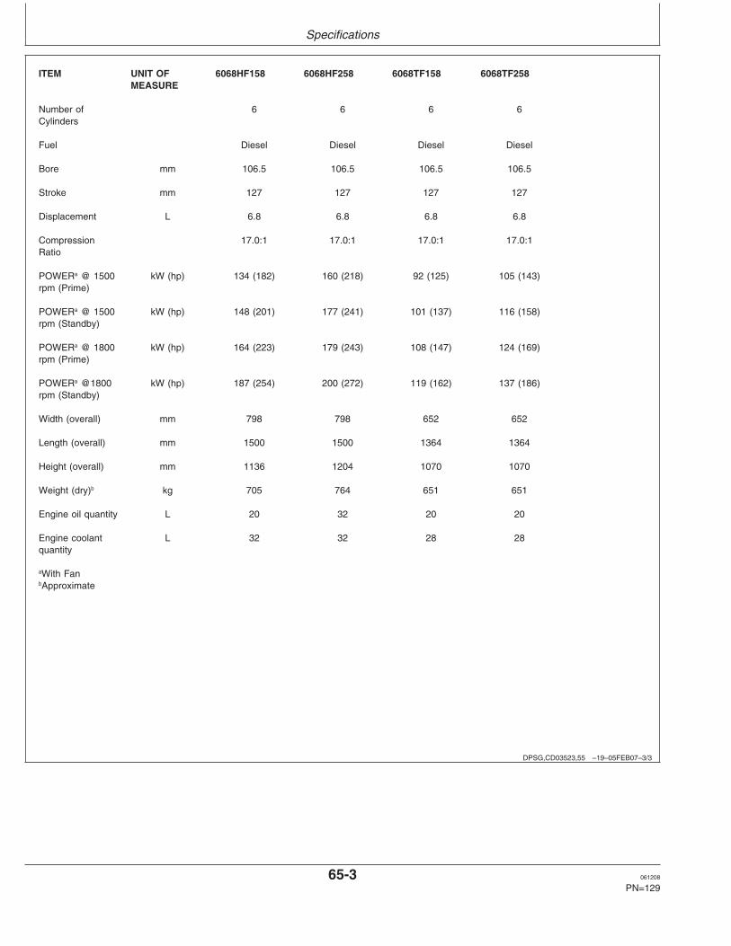
Specifications
DPSG,CD03523,55 –19–05FEB07–3/3
ITEM UNIT OF 6068HF158 6068HF258 6068TF158 6068TF258MEASURE
Number of 6 6 6 6Cylinders
Fuel Diesel Diesel Diesel Diesel
Bore mm 106.5 106.5 106.5 106.5
Stroke mm 127 127 127 127
Displacement L 6.8 6.8 6.8 6.8
Compression 17.0:1 17.0:1 17.0:1 17.0:1Ratio
POWERa @ 1500 kW (hp) 134 (182) 160 (218) 92 (125) 105 (143)rpm (Prime)
POWERa @ 1500 kW (hp) 148 (201) 177 (241) 101 (137) 116 (158)rpm (Standby)
POWERa @ 1800 kW (hp) 164 (223) 179 (243) 108 (147) 124 (169)rpm (Prime)
POWERa @1800 kW (hp) 187 (254) 200 (272) 119 (162) 137 (186)rpm (Standby)
Width (overall) mm 798 798 652 652
Length (overall) mm 1500 1500 1364 1364
Height (overall) mm 1136 1204 1070 1070
Weight (dry)b kg 705 764 651 651
Engine oil quantity L 20 32 20 20
Engine coolant L 32 32 28 28quantity
aWith FanbApproximate
65-3 061208
PN=129

Specifications
CD03523,0000194 –19–06JUN08–1/5
General engine pack specifications (Stage IIEmission Certified Engines)
ITEM UNIT OF 3029HFS70 3029HFU70 3029TFS70 3029TFU70MEASURE
Number of 3 3 3 3Cylinders
Fuel Diesel Diesel Diesel Diesel
Bore mm 106.5 106.5 106.5 106.5
Stroke mm 110 110 110 110
Displacement L 2.9 2.9 2.9 2.9
Compression 17.2:1 17.2:1 17.2:1 17.2:1Ratio
POWERa @ 1500 kW (hp) 37 (50) 37 (50) 28 (37) 28 (37)rpm (Prime)
POWERa @ 1500 kW (hp) 41 (56) 41 (56) 31 (41) 31 (41)rpm (Standby)
POWERa @ 1800 kW (hp)rpm (Prime)
POWERa @1800 kW (hp)rpm (Standby)
Width (overall) mm 582 582 582 582
Length (overall) mm 888 888 888 888
Height (overall) mm 974 974 974 974
Weight (dry)b kg 350 350 350 350
Engine oil quantity L 8 8 8 8
Engine coolant L 14.5 14.5 14.5 14.5quantity
aWith FanbApproximate
Continued on next page
65-4 061208
PN=130
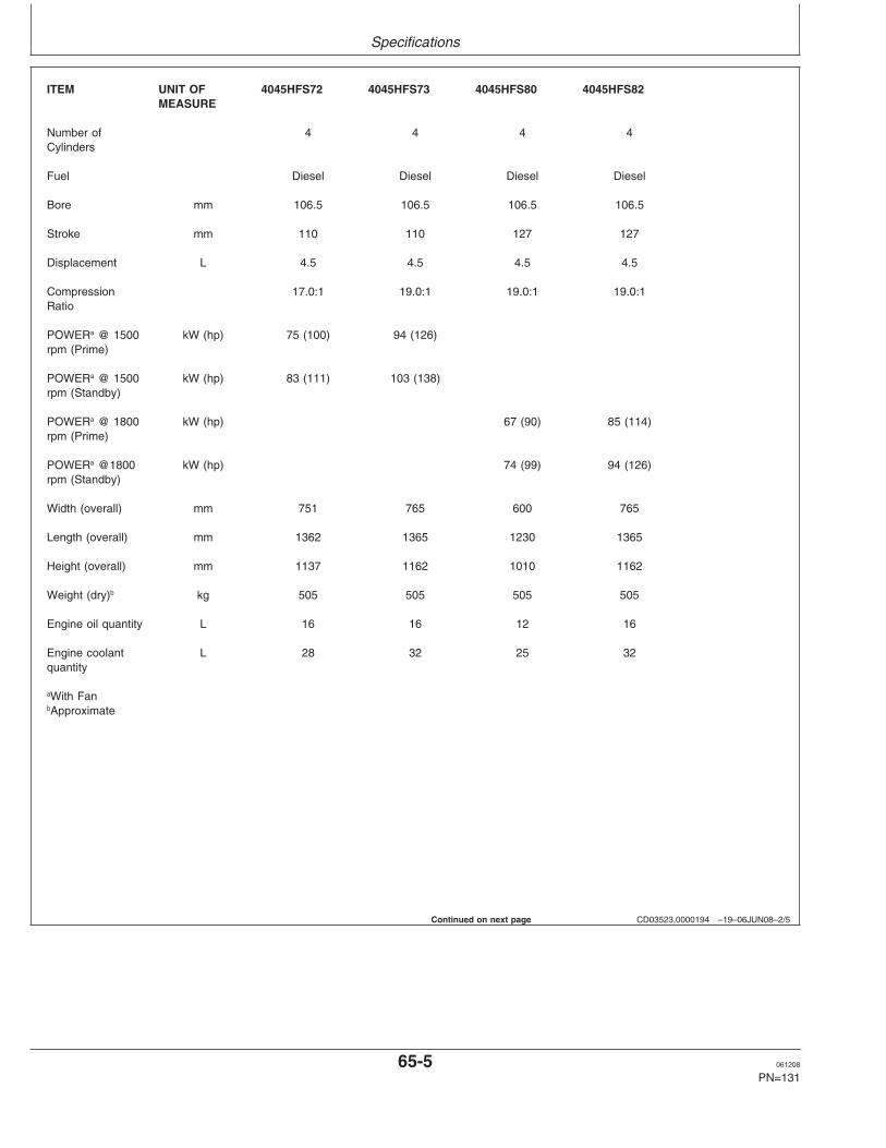
Specifications
CD03523,0000194 –19–06JUN08–2/5
ITEM UNIT OF 4045HFS72 4045HFS73 4045HFS80 4045HFS82MEASURE
Number of 4 4 4 4Cylinders
Fuel Diesel Diesel Diesel Diesel
Bore mm 106.5 106.5 106.5 106.5
Stroke mm 110 110 127 127
Displacement L 4.5 4.5 4.5 4.5
Compression 17.0:1 19.0:1 19.0:1 19.0:1Ratio
POWERa @ 1500 kW (hp) 75 (100) 94 (126)rpm (Prime)
POWERa @ 1500 kW (hp) 83 (111) 103 (138)rpm (Standby)
POWERa @ 1800 kW (hp) 67 (90) 85 (114)rpm (Prime)
POWERa @1800 kW (hp) 74 (99) 94 (126)rpm (Standby)
Width (overall) mm 751 765 600 765
Length (overall) mm 1362 1365 1230 1365
Height (overall) mm 1137 1162 1010 1162
Weight (dry)b kg 505 505 505 505
Engine oil quantity L 16 16 12 16
Engine coolant L 28 32 25 32quantity
aWith FanbApproximate
Continued on next page
65-5 061208
PN=131

Specifications
CD03523,0000194 –19–06JUN08–3/5
ITEM UNIT OF 4045HFS83 4045HFU72 4045HFU79 4045TFU70MEASURE
Number of 4 4 4 4Cylinders
Fuel Diesel Diesel Diesel Diesel
Bore mm 106.5 106.5 106.5 106.5
Stroke mm 110 127 127 127
Displacement L 4.5 4.5 4.5 4.5
Compression 19.0:1 17.0:1 19.0:1 17.0:1Ratio
POWERa @ 1500 kW (hp) 75 (100) 94 (126) 55 (75)rpm (Prime)
POWERa @ 1500 kW (hp) 83 (111) 103 (138) 61 (83)rpm (Standby)
POWERa @ 1800 kW (hp) 107 (143)rpm (Prime)
POWERa @1800 kW (hp) 118 (158)rpm (Standby)
Width (overall) mm 765 751 765 600
Length (overall) mm 1365 1362 1365 1230
Height (overall) mm 1162 1137 1162 1010
Weight (dry)b kg 505 505 505 505
Engine oil quantity L 16 16 16 12
Engine coolant L 32 28 32 25quantity
aWith FanbApproximate
Continued on next page
65-6 061208
PN=132

Specifications
CD03523,0000194 –19–06JUN08–4/5
ITEM UNIT OF 6068HFS72 6068HFS73 6068HFS76 6068HFS77 6068HFS82MEASURE
Number of 6 6 6 6 6Cylinders
Fuel Diesel Diesel Diesel Diesel Diesel
Bore mm 106.5 106.5 106.5 106.5 106.5
Stroke mm 127 127 127 127 127
Displacement L 6.8 6.8 6.8 6.8 6.8
Compression 17.0:1 19.0:1 17.0:1 17.0:1 19.0:1Ratio
POWERa @ 1500 kW (hp) 112 (150) 139 (186) 167 (224) 189 (253)rpm (Prime)
POWERa @ 1500 kW (hp) 123 (165) 153 (205) 184 (247) 207 (277))rpm (Standby)
POWERa @ 1800 kW (hp) 134 (180)rpm (Prime)
POWERa @1800 kW (hp) 147 (197)rpm (Standby)
Width (overall) mm 784 784 960 960 784
Length (overall) mm 1500 1500 1509 1509 1500
Height (overall) mm 1137 1137 1381 1381 1137
Weight (dry)b kg 764 764 764 764 764
Engine oil quantity L 32 32 32 32 32
Engine coolant L 32 32 35 35 32quantity
aWith FanbApproximate
Continued on next page
65-7 061208
PN=133

Specifications
CD03523,0000194 –19–06JUN08–5/5
ITEM UNIT OF 6068HFS83 6068HFS89 6068HFU72 6068HFU74 6068HFU79MEASURE
Number of 6 6 6 6 6Cylinders
Fuel Diesel Diesel Diesel Diesel Diesel
Bore mm 106.5 106.5 106.5 106.5 106.5
Stroke mm 127 127 127 127 127
Displacement L 6.8 6.8 6.8 6.8 6.8
Compression 19.0:1 17.0:1 17.0:1 17.0:1 19.0:1Ratio
POWERa @ 1500 kW (hp) 111 (149) 166(223) / 188 139 (186)rpm (Prime) (252)
POWERa @ 1500 kW (hp) 123 (165) 184 (247) / 207 153 (205)rpm (Standby) (277))
POWERa @ 1800 kW (hp) 161(216) 214 (287) 191(256)rpm (Prime)
POWERa @1800 kW (hp) 177 (237) 235 (315) 201 (269)rpm (Standby)
Width (overall) mm 784 960 784 960 812
Length (overall) mm 1500 1509 1500 1509 1532
Height (overall) mm 1137 1381 1137 1381 1200
Weight (dry)b kg 764 764 764 764 764
Engine oil quantity L 32 32 32 32 32
Engine coolant L 32 35 32 35 32quantity
aWith FanbApproximate
65-8 061208
PN=134

Specifications
DX,TORQ1 –19–24APR03–1/1
Unified Inch Bolt and Screw Torque ValuesTS1671 –UN–01MAY03
Bolt or SAE Grade 1 SAE Grade 2a SAE Grade 5, 5.1 or 5.2 SAE Grade 8 or 8.2
Screw Lubricatedb Dryc Lubricatedb Dryc Lubricatedb Dryc Lubricatedb Dryc
Size N•m lb-in N•m lb-in N•m lb-in N•m lb-in N•m lb-in N•m lb-in N•m lb-in N•m lb-in
1/4 3.7 33 4.7 42 6 53 7.5 66 9.5 84 12 106 13.5 120 17 150
N•m lb-ft N•m lb-ft
5/16 7.7 68 9.8 86 12 106 15.5 137 19.5 172 25 221 28 20.5 35 26
N•m lb-ft N•m lb-ft
3/8 13.5 120 17.5 155 22 194 27 240 35 26 44 32.5 49 36 63 46
N•m lb-ft N•m lb-ft N•m lb-ft
7/16 22 194 28 20.5 35 26 44 32.5 56 41 70 52 80 59 100 74
N•m lb-ft
1/2 34 25 42 31 53 39 67 49 85 63 110 80 120 88 155 115
9/16 48 35.5 60 45 76 56 95 70 125 92 155 115 175 130 220 165
5/8 67 49 85 63 105 77 135 100 170 125 215 160 240 175 305 225
3/4 120 88 150 110 190 140 240 175 300 220 380 280 425 315 540 400
7/8 190 140 240 175 190 140 240 175 490 360 615 455 690 510 870 640
1 285 210 360 265 285 210 360 265 730 540 920 680 1030 760 1300 960
1-1/8 400 300 510 375 400 300 510 375 910 670 1150 850 1450 1075 1850 1350
1-1/4 570 420 725 535 570 420 725 535 1280 945 1630 1200 2050 1500 2600 1920
1-3/8 750 550 950 700 750 550 950 700 1700 1250 2140 1580 2700 2000 3400 2500
1-1/2 990 730 1250 930 990 730 1250 930 2250 1650 2850 2100 3600 2650 4550 3350
Torque values listed are for general use only, based on the strength of the Replace fasteners with the same or higher grade. If higherbolt or screw. DO NOT use these values if a different torque value or grade fasteners are used, tighten these to the strength of thetightening procedure is given for a specific application. For plastic insert or original. Make sure fastener threads are clean and that youcrimped steel type lock nuts, for stainless steel fasteners, or for nuts on properly start thread engagement. When possible, lubricateU-bolts, see the tightening instructions for the specific application. Shear plain or zinc plated fasteners other than lock nuts, wheel boltsbolts are designed to fail under predetermined loads. Always replace shear or wheel nuts, unless different instructions are given for thebolts with identical grade. specific application.aGrade 2 applies for hex cap screws (not hex bolts) up to 6. in (152 mm) long. Grade 1 applies for hex cap screws over 6 in. (152 mm) long,and for all other types of bolts and screws of any length.b“Lubricated” means coated with a lubricant such as engine oil, fasteners with phosphate and oil coatings, or 7/8 in. and larger fasteners withJDM F13C zinc flake coating.c“Dry” means plain or zinc plated without any lubrication, or 1/4 to 3/4 in. fasteners with JDM F13B zinc flake coating.
65-9 061208
PN=135

Specifications
DX,TORQ2 –19–24APR03–1/1
Metric Bolt and Screw Torque Values
4.84.8 8.8 9.8 10.9 12.9 12.9
12.912.910.99.88.84.8
TS
1670
–UN
–01M
AY
03
Bolt or Class 4.8 Class 8.8 or 9.8 Class 10.9 Class 12.9
Screw Lubricateda Dryb Lubricateda Dryb Lubricateda Dryb Lubricateda Dryb
Size N•m lb-in N•m lb-in N•m lb-in N•m lb-in N•m lb-in N•m lb-in N•m lb-in N•m lb-in
M6 4.7 42 6 53 8.9 79 11.3 100 13 115 16.5 146 15.5 137 19.5 172
N•m lb-ft N•m lb-ft N•m lb-ft N•m lb-ft
M8 11.5 102 14.5 128 22 194 27.5 243 32 23.5 40 29.5 37 27.5 47 35
N•m lb-ft N•m lb-ft N•m lb-ft
M10 23 204 29 21 43 32 55 40 63 46 80 59 75 55 95 70
N•m lb-ft
M12 40 29.5 50 37 75 55 95 70 110 80 140 105 130 95 165 120
M14 63 46 80 59 120 88 150 110 175 130 220 165 205 150 260 190
M16 100 74 125 92 190 140 240 175 275 200 350 255 320 235 400 300
M18 135 100 170 125 265 195 330 245 375 275 475 350 440 325 560 410
M20 190 140 245 180 375 275 475 350 530 390 675 500 625 460 790 580
M22 265 195 330 245 510 375 650 480 725 535 920 680 850 625 1080 800
M24 330 245 425 315 650 480 820 600 920 680 1150 850 1080 800 1350 1000
M27 490 360 625 460 950 700 1200 885 1350 1000 1700 1250 1580 1160 2000 1475
M30 660 490 850 625 1290 950 1630 1200 1850 1350 2300 1700 2140 1580 2700 2000
M33 900 665 1150 850 1750 1300 2200 1625 2500 1850 3150 2325 2900 2150 3700 2730
M36 1150 850 1450 1075 2250 1650 2850 2100 3200 2350 4050 3000 3750 2770 4750 3500
Torque values listed are for general use only, based on the strength Shear bolts are designed to fail under predetermined loads. Alwaysof the bolt or screw. DO NOT use these values if a different torque replace shear bolts with identical property class. Replace fastenersvalue or tightening procedure is given for a specific application. For with the same or higher property class. If higher property classstainless steel fasteners or for nuts on U-bolts, see the tightening fasteners are used, tighten these to the strength of the original. Makeinstructions for the specific application. Tighten plastic insert or sure fastener threads are clean and that you properly start threadcrimped steel type lock nuts by turning the nut to the dry torque engagement. When possible, lubricate plain or zinc plated fastenersshown in the chart, unless different instructions are given for the other than lock nuts, wheel bolts or wheel nuts, unless differentspecific application. instructions are given for the specific application.a“Lubricated” means coated with a lubricant such as engine oil, fasteners with phosphate and oil coatings, or M20 and larger fasteners withJDM F13C zinc flake coating.b“Dry” means plain or zinc plated without any lubrication, or M6 to M18 fasteners with JDM F13B zinc flake coating.
65-10 061208
PN=136
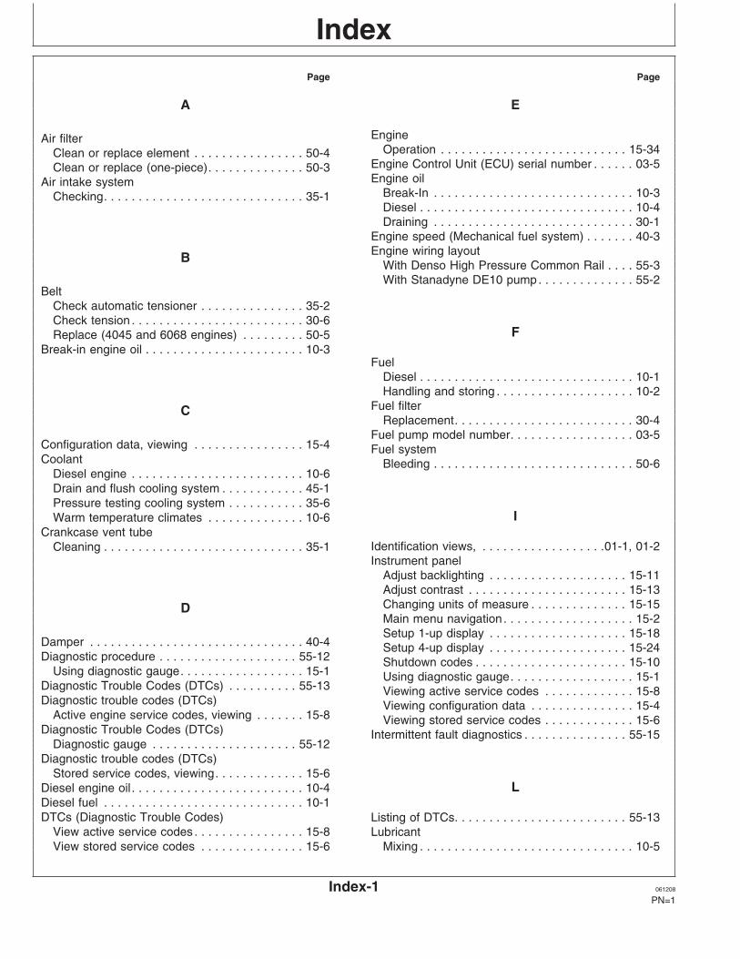
IndexPage Page
A E
EngineAir filterOperation . . . . . . . . . . . . . . . . . . . . . . . . . . . 15-34Clean or replace element . . . . . . . . . . . . . . . . 50-4
Engine Control Unit (ECU) serial number . . . . . . 03-5Clean or replace (one-piece). . . . . . . . . . . . . . 50-3Engine oilAir intake system
Break-In . . . . . . . . . . . . . . . . . . . . . . . . . . . . . 10-3Checking. . . . . . . . . . . . . . . . . . . . . . . . . . . . . 35-1Diesel . . . . . . . . . . . . . . . . . . . . . . . . . . . . . . . 10-4Draining . . . . . . . . . . . . . . . . . . . . . . . . . . . . . 30-1
Engine speed (Mechanical fuel system) . . . . . . . 40-3Engine wiring layoutB
With Denso High Pressure Common Rail . . . . 55-3With Stanadyne DE10 pump. . . . . . . . . . . . . . 55-2
BeltCheck automatic tensioner . . . . . . . . . . . . . . . 35-2Check tension . . . . . . . . . . . . . . . . . . . . . . . . . 30-6
FReplace (4045 and 6068 engines) . . . . . . . . . 50-5Break-in engine oil . . . . . . . . . . . . . . . . . . . . . . . 10-3
FuelDiesel . . . . . . . . . . . . . . . . . . . . . . . . . . . . . . . 10-1Handling and storing . . . . . . . . . . . . . . . . . . . . 10-2
Fuel filterCReplacement. . . . . . . . . . . . . . . . . . . . . . . . . . 30-4
Fuel pump model number. . . . . . . . . . . . . . . . . . 03-5Configuration data, viewing . . . . . . . . . . . . . . . . 15-4 Fuel systemCoolant Bleeding . . . . . . . . . . . . . . . . . . . . . . . . . . . . . 50-6
Diesel engine . . . . . . . . . . . . . . . . . . . . . . . . . 10-6Drain and flush cooling system . . . . . . . . . . . . 45-1Pressure testing cooling system . . . . . . . . . . . 35-6
IWarm temperature climates . . . . . . . . . . . . . . 10-6Crankcase vent tube
Identification views, . . . . . . . . . . . . . . . . . .01-1, 01-2Cleaning . . . . . . . . . . . . . . . . . . . . . . . . . . . . . 35-1Instrument panel
Adjust backlighting . . . . . . . . . . . . . . . . . . . . 15-11Adjust contrast . . . . . . . . . . . . . . . . . . . . . . . 15-13Changing units of measure . . . . . . . . . . . . . . 15-15DMain menu navigation. . . . . . . . . . . . . . . . . . . 15-2Setup 1-up display . . . . . . . . . . . . . . . . . . . . 15-18
Damper . . . . . . . . . . . . . . . . . . . . . . . . . . . . . . . 40-4 Setup 4-up display . . . . . . . . . . . . . . . . . . . . 15-24Diagnostic procedure . . . . . . . . . . . . . . . . . . . . 55-12 Shutdown codes . . . . . . . . . . . . . . . . . . . . . . 15-10
Using diagnostic gauge. . . . . . . . . . . . . . . . . . 15-1 Using diagnostic gauge. . . . . . . . . . . . . . . . . . 15-1Diagnostic Trouble Codes (DTCs) . . . . . . . . . . 55-13 Viewing active service codes . . . . . . . . . . . . . 15-8Diagnostic trouble codes (DTCs) Viewing configuration data . . . . . . . . . . . . . . . 15-4
Active engine service codes, viewing . . . . . . . 15-8 Viewing stored service codes . . . . . . . . . . . . . 15-6Diagnostic Trouble Codes (DTCs) Intermittent fault diagnostics . . . . . . . . . . . . . . . 55-15
Diagnostic gauge . . . . . . . . . . . . . . . . . . . . . 55-12Diagnostic trouble codes (DTCs)
Stored service codes, viewing. . . . . . . . . . . . . 15-6LDiesel engine oil . . . . . . . . . . . . . . . . . . . . . . . . . 10-4
Diesel fuel . . . . . . . . . . . . . . . . . . . . . . . . . . . . . 10-1DTCs (Diagnostic Trouble Codes) Listing of DTCs. . . . . . . . . . . . . . . . . . . . . . . . . 55-13
View active service codes . . . . . . . . . . . . . . . . 15-8 LubricantMixing . . . . . . . . . . . . . . . . . . . . . . . . . . . . . . . 10-5View stored service codes . . . . . . . . . . . . . . . 15-6
Index-1 061208
PN=1

Index
Page Page
Storage . . . . . . . . . . . . . . . . . . . . . . . . . . . . . . 10-5 S
Serial numberEngine Control Unit (ECU) . . . . . . . . . . . . . . . 03-5
M High-pressure fuel pump. . . . . . . . . . . . . . . . . 03-5Serial numbers
Maintenance Engine Control Unit (ECU) serial number . . . . 03-5As required Engine option codes . . . . . . . . . . . . . . . . . . . . 03-3
Additional service information . . . . . . . . . . . 50-1 Engine serial number plate . . . . . . . . . . . . . . . 03-1Clean or replace air filter element . . . . . . . . 50-4 Fuel pump model number . . . . . . . . . . . . . . . . 03-5Clean or replace air filter (one-piece). . . . . . 50-3 POWERTech label . . . . . . . . . . . . . . . . . . . . . 03-1Do not modify fuel system . . . . . . . . . . . . . . 50-2 Record engine serial number . . . . . . . . . . . . . 03-2Replace fan and alternator belts (4045 and 6068 Record fuel injection pump model number . . . 03-5
engines) . . . . . . . . . . . . . . . . . . . . . . . . . . 50-5 SpecificationsDaily or every 10 hours. . . . . . . . . . . . . . . . . . 25-1 Engine PackObserve service intervals . . . . . . . . . . . . . . . . 20-1 Non-Emission Certified Engines . . . . . . . . . 65-1Use correct fuel, lubricant and coolant . . . . . . 20-1 Stage II Emission Certified Engines. . . . . . . 65-41000 hours/1 year Storage
Check and adjust valve clearance (3029 and Engine . . . . . . . . . . . . . . . . . . . . . . . . . . . . . . 60-14039 engines) . . . . . . . . . . . . . . . . . . . . . 35-4 Storing fuel . . . . . . . . . . . . . . . . . . . . . . . . . . . . . 10-2
Checking air intake system . . . . . . . . . . . . . 35-1 Storing lubricants . . . . . . . . . . . . . . . . . . . . . . . . 10-5Checking automatic belt tensioner (4045 and
6068 Engines) . . . . . . . . . . . . . . . . . . . . . 35-2Cleaning crankcase vent tube . . . . . . . . . . . 35-1
TPressure testing cooling system . . . . . . . . . 35-62000 hours/2 years
Trouble codes . . . . . . . . . . . . . . . . . . . . . . . . . 55-13Adjust speed droop governor (Mechanical fuelTroubleshootingsystem) . . . . . . . . . . . . . . . . . . . . . . . . . . 40-3
Electrical . . . . . . . . . . . . . . . . . . . . . . . . . . . . . 55-9Adjust valve clearance (4045 and 6068Engine . . . . . . . . . . . . . . . . . . . . . . . . . . . . . . 55-4engines) . . . . . . . . . . . . . . . . . . . . . . . . . . 40-1General information. . . . . . . . . . . . . . . . . . . . . 55-1Check engine speed (Mechanical fuel
system) . . . . . . . . . . . . . . . . . . . . . . . . . . 40-3Damper check . . . . . . . . . . . . . . . . . . . . . . . 40-4
2500 hours/3 years UDrain and flush cooling system . . . . . . . . . . 45-1
500 hours Units of measure, changing . . . . . . . . . . . . . . . 15-15Changing engine oil and filter . . . . . . . . . . . 30-1Checking belt. . . . . . . . . . . . . . . . . . . . . . . . 30-6Replace fuel filter. . . . . . . . . . . . . . . . . . . . . 30-4
VMaintenance records . . . . . . . . . . . . . . . . . . . . . 02-1Mixing lubricants. . . . . . . . . . . . . . . . . . . . . . . . . 10-5
Valve clearanceAdjust (3029 and 4039 engines) . . . . . . . . . . . 35-4Adjust (4045 and 6068 engines) . . . . . . . . . . . 40-1
O
Operating the engineWBreak-in period . . . . . . . . . . . . . . . . . . . . . . . 15-29
Changing Generator Frequency . . . . . . . . . . 15-35Wiring harnessStandby power units . . . . . . . . . . . . . . . . . . . 15-34
With Denso High Pressure Common Rail . . . . 55-3Starting the engine . . . . . . . . . . . . . . . . . . . . 15-30With Stanadyne DE10 pump. . . . . . . . . . . . . . 55-2Stopping the engine . . . . . . . . . . . . . . . . . . . 15-35
Using a booster battery or charger . . . . . . . . 15-33
Index-2 061208
PN=2