power up your plant - an introduction to integrated ... · for integrated process and power...
TRANSCRIPT

Executive Summary Document ID: 3BUS095060 Page 1 Date: 8/21/2010 © Copyright 2010 ABB. All rights reserved. Pictures, schematics and other graphics contained herein are published for illustration purposes only and do not represent product configurations or functionality.
Power Up Your Plant
An introduction to integrated process and power
automation
Jeffrey Vasel
ABB, Inc.
August 21, 2010
Rev 2
Abstract
This paper discusses how a single integrated system can increase energy efficiency, improve
plant uptime, and lower life cycle costs. Often referred to as Electrical Integration, Integrated
Process and Power Automation is a new system integration architecture and power strategy that
addresses the needs of the process and power generation industries. The architecture is based on
Industrial Ethernet standards such as IEC 61850 and Profinet as well as Fieldbus technologies.
Emphasis is placed on tying the IEC 61850 substation automation standard with the process
control system. The energy efficiency gains from integration are discussed in a power generation
use case. In this use case energy efficiency is realized with integrated variable frequency drives,
improved visibility into power consumption, and energy efficiency through faster plant startup
times. Demonstrated capital expenditure (CAPEX) savings is discussed in a cost avoidance
section where a real world example of wiring savings is described. Lastly a power management
success story from a major oil and gas company, Petrobras, is discussed. In this case, Petrobras
utilized integrated process and power automation to lower CAPEX, operational expenditure
(OPEX), and explore future energy saving opportunities. This paper was originally published for
the World Energy Congress – Montreal show scheduled for September 2010. Updates and
additions have been made throughout the document.

Executive Summary Document ID: 3BUS095060 Page 2 Date: 8/21/2010 © Copyright 2010 ABB. All rights reserved. Pictures, schematics and other graphics contained herein are published for illustration purposes only and do not represent product configurations or functionality.
Document ID: 3BUS095060 Page 27 Date: 8/21/2010 © Copyright 2010 ABB. All rights reserved. Pictures, schematics and other graphics contained herein are published for illustration purposes only and may not represent product configurations or functionality.
References 1 Pipeline and Gas Journal, October 2009, “Integrated Power and Automation
Systems: Future trends for pipeline system efficiency”, Jeffrey Vasel
2 “Future power plant control – Integrating process and substation automation into
one system”, Joerg Orth, ABB AG, Mannheim, Germany
3 “Benefits of IEC 61850 Networking” presentation from UCA International Users
Group, Ralph Mackiewicz, SISCO, Inc.
4 Power magazine, Volume 153, No 2, February 2009, “Optimize your plant using
the latest distributed control system technology”, Ralph Porfilio
5 Energy efficient design of auxiliary systems in fossil–fuel power plants, ABB
Inc. in collaboration with Rocky Mountain Institute USA, December 2009
Keywords DCS – Distributed Control System
ECS – Electrical Control System
TCS – Turbine Control System
IED – Intelligent Electrical Device
LV – Low Voltage
MV – Medium Voltage
HV – High Voltage
SA – Substation Automation
IEC 61850 – International Electrotechnical Commission’s substation automation standard
ANSI – American National Standards Institute
PID – Proportional Integral Derivative Control Algorithm
HART – Highway Addressable Remote Transducer Protocol
AO – Asset Optimization
CMMS – Computerized Maintenance Management System
SOE – Sequence of Events
NERC - North American Electric Reliability Council
CIP – Critical Infrastructure Protection
LN – Logical Node
OPC – OLE for Process Control standard for soft interface over Ethernet
GOOSE – Generic Object Oriented Substation Event
MMS – Manufacture Messaging Specification
SLD – Single Line Diagram
SNTP – Simple Network Time Protocol
EMI – Electromagnetic Interference
Document ID: 3BUS095060 Page 26 Date: 8/21/2010 © Copyright 2010 ABB. All rights reserved. Pictures, schematics and other graphics contained herein are published for illustration purposes only and do not represent product configurations or functionality.
Conclusion Integrated process and power automation architecture can improve plant uptime, increase
energy efficiency, and lower life cycle costs for heavy users of electricity including power
generation plants, oil and gas industries, chemical plants, and pulp and paper mills. Energy
efficiency can be gained through integration by improved visibility into power consumption,
integrated drives, and faster plant startups. Refineries and other major consumers of electricity
are experiencing lower CAPEX with Electrical Integration. Silos can be broken among
operators, engineers, and managers with an integrated system making more efficient end-
users. It allows for quicker time to problem resolution with a centralized plant maintenance
system. Plant upsets can be resolved more quickly with a plantwide sequence of events list. A
smaller system footprint can reduce spare part inventories, lower training time for users, and
make for a simpler overall system design with fewer wires, yet more connectivity. The use of
Industrial Ethernets such as the IEC 61850 standard is being embraced globally as the enabler
for integrated process and power automation architecture.
Document ID: 3BUS095060 Page 3 Date: 8/21/2010 © Copyright 2010 ABB. All rights reserved. Pictures, schematics and other graphics contained herein are published for illustration purposes only and may not represent product configurations or functionality.
This page left intentionally blank.

Document ID: 3BUS095060 Page 4 Date: 8/21/2010 © Copyright 2010 ABB. All rights reserved. Pictures, schematics and other graphics contained herein are published for illustration purposes only and may not represent product configurations or functionality.
What is integrated process and power automation? Integrated process and power automation is a unified architecture that combines process
controls, process electrification, and power management and distribution into one system.
Often referred to as Electrical Integration, integrated process and power automation is a new
system integration architecture and power strategy that addresses the needs of many process
industry segments. Electrical Integration is the next frontier in driving energy efficiency,
increasing availability and operator effectiveness, and reducing costs.
A typical process control plant can be divided into three areas: Process Control, Process
Electrification, and Power Management and Distribution as shown in Figure 1.
Process Control
Includes instrumentation, safety systems, and controllers. Here these devices
communicate using a variety of fieldbus protocols including Profibus, Foundation
Fieldbus, and HART.
Process Electrification
Includes low voltage (LV) drives, motors, switchgear, and circuit breakers. These
devices typically communicate with the control system via Profibus and Modbus.
Profinet is now making its debut into the Process Electrification area.
Power Management and Distribution
Corresponds to Substation Automation (SA) systems. It hosts medium voltage (MV)
and high voltage (HV) power equipment including protective relays, also known as
Intelligent Electrical Devices (IEDs), transformers, instrument transformers, power
meters, drives, and motors.
This architecture is primarily for industries that consume a great deal of energy. These
industries have different objectives. The oil and gas industry wants to maximize production,
so production facilities need to do fast load shedding during power interruptions to keep their
critical processes running. Mining and minerals processing facilities also want to maximize
production but they need a consistent and reliable supply of energy, as well as efficient power
distribution. Power generation facilities desire to create a reliable supply of energy and reduce
their own auxiliary system’s energy consumption. Pulp and paper mills need to manage
electricity as a raw material cost by addressing high energy consumption through peak
shaving.
Document ID: 3BUS095060 Page 25 Date: 8/21/2010 © Copyright 2010 ABB. All rights reserved. Pictures, schematics and other graphics contained herein are published for illustration purposes only and may not represent product configurations or functionality.
cabling is needed when implementing IEC 61850 technology with the DCS. Critical data is
now shared between the DCS and the substation automation system via Ethernet instead of
using hundreds of hard-wired signal cables. An integrated architecture creates a more
simplified system. For example, Petrobras has a single tool set for engineering and device
integration. This simplification in the overall system design equated to faster project
execution, testing, and commissioning with a 25 to 30% reduction in overall project execution
time. Petrobras is beginning to realize lower life cycle costs. Initially, Petrobras has reduced
training costs by 20%. Next, Petrobras is optimizing maintenance through integration of
maintenance practices among instrumentation, motors, power devices, and IT systems. Their
goal is to reduce unscheduled downtime and increase availability through online monitoring
of critical assets using both real-time and historical data. The data is made available remotely
to centralized and outsourced maintenance centers.
Petrobras has a long term vision for energy efficiency, and it is part of the company’s overall
strategic plan. They realize energy efficiency is good for business financially and through an
improved image with its customers, environmental groups, and society in general. Petrobras is
looking for energy savings from improved visibility into power usage and equipment
performance. The top areas of concern are motor systems, combined heat and power, steam
systems, and energy recovery systems. Their focus will be on integrated process and power
automation systems, high performance drives, advanced controls, emission controls, and
modernization of existing sites.
Long term operational costs will be minimized as the architecture provides a more reliable
system with fewer assets, spare parts protocols, and wiring. Energy costs can more easily be
managed and reduced with a unified system. With a common platform from ABB, Petrobras
is experiencing lower maintenance and life cycle costs, capital cost savings, and efficient
engineering by integrated project teams.
Figure 11 – Petrobras after integrated process and power automation

Document ID: 3BUS095060 Page 24 Date: 8/21/2010 © Copyright 2010 ABB. All rights reserved. Pictures, schematics and other graphics contained herein are published for illustration purposes only and do not represent product configurations or functionality.
Petrobras succeeds with integration at the REPAR refinery
Petrobras is a major energy company based in Brazil with over 100 platforms, 16 refineries,
and 6000 gas stations. They are faced with many challenges as they expand their Substation
Automation infrastructure. See Figure 10. Petrobras needs to integrate new ABB substations
with legacy power management systems. The PMS functionality and data need to be shared
with both the new and legacy systems. At the same time, they are looking for better
performance, reliability, and system information.
Figure 10 – Petrobras before integrated process and power automation
Petrobras needed a future proof technology with a simplified design that will allow for easy
future expansion. They implemented ABB’s integrated process and power architecture by
using IEC 61850 technology at their REPAR refinery. The REPAR refinery is located
approximately 400 km south of Sao Paolo. The solution provides a unique and open concept
with one control library, one control system, and one common IEC 61850 engineering toolset.
See Figure 11. With a common system, standardization on operational and maintenance
procedures is easier.
The combination of the substation automation system with the System 800xA DCS has
brought benefits to Petrobras in many areas including standardization, lower investment costs,
integration of maintenance practices, simplification in project execution, and lower life cycle
costs. When dealing with new and legacy systems, it is critical to have standardized
procedures, settings, control logic, controller libraries, and operational and maintenance
procedures.
Standardization is easier and practical with an integrated system compared to working with
disparate systems and technologies. Petrobras has experienced lower investment costs with a
combined system including 30% less man hours due to reuse of engineering data. Less
Document ID: 3BUS095060 Page 5 Date: 8/21/2010 © Copyright 2010 ABB. All rights reserved. Pictures, schematics and other graphics contained herein are published for illustration purposes only and may not represent product configurations or functionality.
Figure 1 – Integrated process and power automation for a typical process plant system
The IEC 61850 standard and the DCS Electrical Integration in the past has been hampered with lack of communication standards
and architectural design resulting in high project execution and commissioning costs and high
life cycle costs. There are too many protocols used in substation automation systems. Some
are proprietary while others are open standards. No one protocol has become dominant. As a
result, the cost to engineer the SA system is high when multiple vendors supply equipment
that uses different communications protocols. The life cycle costs of a system with a
hodgepodge set of communication links are also very high. In addition, Electrical Integration
is not new. It has been done in the past by hard-wiring signals between the electrical
equipment and the process control system, as well as by building complex software gateways.
Past integration methodologies have high integration costs, high project risks, and high life
cycle costs. See Figure 2. Device specific solutions are needed for integration into the DCS in
addition to a lot of hard-wiring. Critical electrical asset health information is lost. Moreover,
organizational barriers among departments within plants and suppliers have also hampered
integration efforts. A new approach is needed to overcome these barriers1.
Leading process control suppliers are taking advantage of open industry standards including
Fieldbus technology and Industrial Ethernet to optimize commissioning efforts, minimize
project risks, and lower the total cost of ownership. The Electrical Integration architecture is
Extended
Operator
Workplace
Document ID: 3BUS095060 Page 6 Date: 8/21/2010 © Copyright 2010 ABB. All rights reserved. Pictures, schematics and other graphics contained herein are published for illustration purposes only and do not represent product configurations or functionality.
based on Industrial Ethernet standards such as IEC 61850 and Profinet as well as various
Fieldbus technologies including Profibus and Foundation Fieldbus. ABB’s solution integrates
power and process automation systems with the Electrical Integration architecture as seen in
Figure 1.
Control Room
Control
Hardwired
Serial buses
Process
Protection &
Control
IEDs
Controllers
Process
Electrification
Process
Instrumentation
System Network
Fieldbus
Process Workplace
System Network
Protocol 1 Protocol 3
Protocol 2
Gateway/Protocol
Converter
Power SCADA
Server
Power Workplace
Process Control
Server
Instruments LV Switchgear
Drives
Motor starters
Substation
Automation
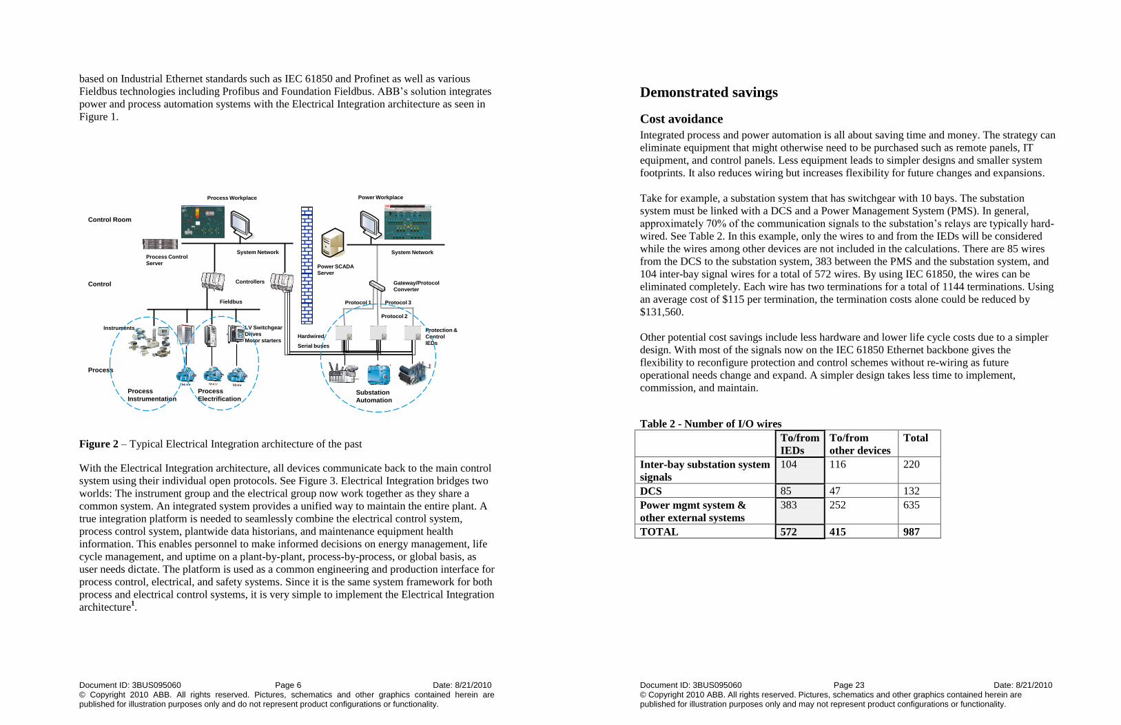
Figure 2 – Typical Electrical Integration architecture of the past
With the Electrical Integration architecture, all devices communicate back to the main control
system using their individual open protocols. See Figure 3. Electrical Integration bridges two
worlds: The instrument group and the electrical group now work together as they share a
common system. An integrated system provides a unified way to maintain the entire plant. A
true integration platform is needed to seamlessly combine the electrical control system,
process control system, plantwide data historians, and maintenance equipment health
information. This enables personnel to make informed decisions on energy management, life
cycle management, and uptime on a plant-by-plant, process-by-process, or global basis, as
user needs dictate. The platform is used as a common engineering and production interface for
process control, electrical, and safety systems. Since it is the same system framework for both
process and electrical control systems, it is very simple to implement the Electrical Integration
architecture1.
Document ID: 3BUS095060 Page 23 Date: 8/21/2010 © Copyright 2010 ABB. All rights reserved. Pictures, schematics and other graphics contained herein are published for illustration purposes only and may not represent product configurations or functionality.
Demonstrated savings
Cost avoidance
Integrated process and power automation is all about saving time and money. The strategy can
eliminate equipment that might otherwise need to be purchased such as remote panels, IT
equipment, and control panels. Less equipment leads to simpler designs and smaller system
footprints. It also reduces wiring but increases flexibility for future changes and expansions.
Take for example, a substation system that has switchgear with 10 bays. The substation
system must be linked with a DCS and a Power Management System (PMS). In general,
approximately 70% of the communication signals to the substation’s relays are typically hard-
wired. See Table 2. In this example, only the wires to and from the IEDs will be considered
while the wires among other devices are not included in the calculations. There are 85 wires
from the DCS to the substation system, 383 between the PMS and the substation system, and
104 inter-bay signal wires for a total of 572 wires. By using IEC 61850, the wires can be
eliminated completely. Each wire has two terminations for a total of 1144 terminations. Using
an average cost of $115 per termination, the termination costs alone could be reduced by
$131,560.
Other potential cost savings include less hardware and lower life cycle costs due to a simpler
design. With most of the signals now on the IEC 61850 Ethernet backbone gives the
flexibility to reconfigure protection and control schemes without re-wiring as future
operational needs change and expand. A simpler design takes less time to implement,
commission, and maintain.
Table 2 - Number of I/O wires
To/from
IEDs
To/from
other devices
Total
Inter-bay substation system
signals
104 116 220
DCS 85 47 132
Power mgmt system &
other external systems
383 252 635
TOTAL 572 415 987
Document ID: 3BUS095060 Page 22 Date: 8/21/2010 © Copyright 2010 ABB. All rights reserved. Pictures, schematics and other graphics contained herein are published for illustration purposes only and do not represent product configurations or functionality.
Single strategy for asset management
More advanced DCS systems are able to optimize plant assets beyond smart instruments with
an integrated asset optimization system. Integrated process and power automation architecture
allows plant electrical equipment health to be added to the process control system’s asset
optimization system providing a single view for all critical process and electrical plant assets.
See Table 1 for a list of asset monitors for both process and electrical equipment. An asset
monitor is a software component that promptly reports one or more health conditions of an
asset. Maintenance planning becomes more efficient since we now have a single source of
data for maintenance analysis. Less time is spent planning, leaving more time for actual
maintenance work.
Table 1 List of Asset Monitors
Process Electrical
Instrumentation Transformers
Rotating Equipment LV Circuit Breakers
Vibration UMC 22 Motor
Starters
DCS Controller Health MNS iS LV
Switchgear
IT Assets Motors
Heat Exchangers Drives
Control Loops Protective Relays
Other Process Plant
Equipment
Other Electrical
Equipment
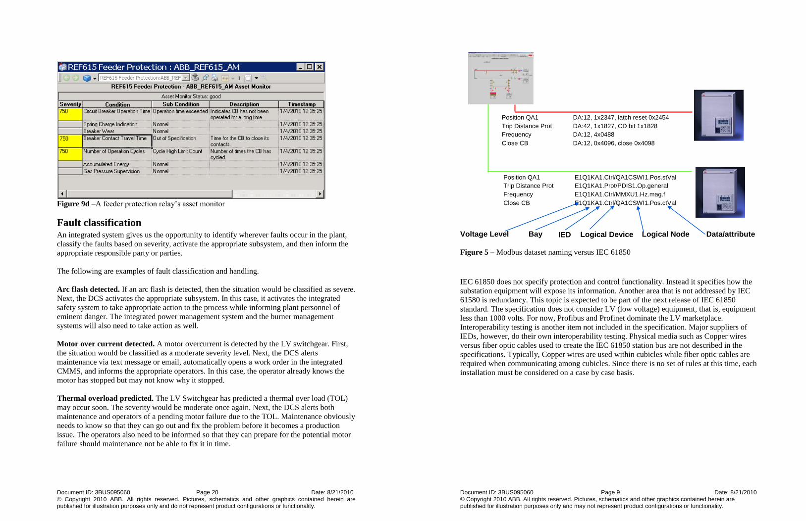
A centralized system provides operators, engineers, and maintenance personnel with relevant
actionable data to prevent plant upsets and predict equipment failures. For example, advanced
feeder protection relays can predict time remaining in a circuit breaker’s life. This information
is buffered locally in an RCB and is fed vertically into the asset optimization system via MMS
and then read by asset monitors. A feeder protection relay’s asset monitor is reporting a
problem with the breaker contact travel time. Refer to Figure 9d. In this scenario, the circuit
breaker is taking too long to open or close. The operator who is immediately alerted to the
problem, reports it to the appropriate maintenance person. With a common user environment
for operations and maintenance, operators and maintenance personnel can work together to
troubleshoot problems more quickly and avoid plant upsets.
Document ID: 3BUS095060 Page 7 Date: 8/21/2010 © Copyright 2010 ABB. All rights reserved. Pictures, schematics and other graphics contained herein are published for illustration purposes only and may not represent product configurations or functionality.
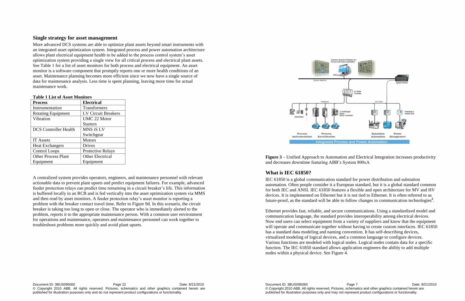
Figure 3 – Unified Approach to Automation and Electrical Integration increases productivity
and decreases downtime featuring ABB’s System 800xA
What is IEC 61850?
IEC 61850 is a global communication standard for power distribution and substation
automation. Often people consider it a European standard, but it is a global standard common
for both IEC and ANSI. IEC 61850 features a flexible and open architecture for MV and HV
devices. It is implemented on Ethernet but it is not tied to Ethernet. It is often referred to as
future-proof, as the standard will be able to follow changes in communication technologies2.
Ethernet provides fast, reliable, and secure communications. Using a standardized model and
communication language, the standard provides interoperability among electrical devices.
Now end users can select equipment from a variety of suppliers and know that the equipment
will operate and communicate together without having to create custom interfaces. IEC 61850
has a standard data modeling and naming convention. It has self-describing devices,
virtualized modeling of logical devices, and a common language to configure devices.
Various functions are modeled with logical nodes. Logical nodes contain data for a specific
function. The IEC 61850 standard allows application engineers the ability to add multiple
nodes within a physical device. See Figure 4.

Document ID: 3BUS095060 Page 8 Date: 8/21/2010 © Copyright 2010 ABB. All rights reserved. Pictures, schematics and other graphics contained herein are published for illustration purposes only and do not represent product configurations or functionality.
Figure 4 – IEC 61850 example structure of a protective relay
3
An example of dataset naming of Modbus versus IEC 61850 is illustrated in Figure 5. The
Modbus dataset must be precisely mapped and must specify the register address. Modbus
does not have a naming standard, so a data dictionary must be created for each Modbus
system design. When two or more suppliers are used on a project, there will be multiple
naming conventions and data mapping issues resulting in extensive testing and
commissioning time. The memory map for a specific IED is sometimes over ninety pages
long and it is different for every device and every supplier. Application engineers would have
to scroll through pages upon pages of memory maps for a written description of the registers
and then map it to its destination point in another set of memory maps. Future changes and
modifications will be difficult and costly to implement. The register address will vary from
device to device, while the IEC 61850 dataset naming is standardized and independent of
register addresses. The case in Figure 5 shows the anatomy of an IEC 61850 standardized
name. It describes the name from the voltage level down to the attributes of a specific piece of
data including bay, IED, logical device, and logical node names. Using IEC 61850 simplifies
SA communication system designs.
Document ID: 3BUS095060 Page 21 Date: 8/21/2010 © Copyright 2010 ABB. All rights reserved. Pictures, schematics and other graphics contained herein are published for illustration purposes only and may not represent product configurations or functionality.
Number of operation hours has been exceeded. For a final example, a preventative
maintenance alert is generated by the LV Switchgear stating that the number of operations
hours has been exceeded. The severity would be classified as low. Next, the DCS
automatically opens a work order in the integrated CMMS, alerts maintenance, but does not
inform the operators. Operators do not need to see information that does not immediately
affect them. Maintenance would then be performed during the next available equipment
downtime.
Single plantwide sequence of events list
With a single plantwide system, troubleshooting plant upsets can be easier and faster. A
common plantwide sequence of events (SoE) list is made available by the integrated system.
This is possible because IEC 61850 uses Simple Network Time Protocol (SNTP) to
synchronize all IEDs on the network. Time-stamped event resolution is 1ms with IEC 61850.
No longer will process control and power engineers need to attempt to match up
unsynchronized event lists from multiple systems. In the mixer example discussed previously,
operators and engineers would be able to troubleshoot the plant disturbance more quickly with
a common, synchronized, plantwide sequence of events list.
A single plantwide system has a smaller footprint. Less servers, switches, and other IT assets
are needed. By using Ethernet, interconnection wiring is reduced or eliminated making a more
simple, overall system design that is easier to build and maintain over the life cycle of the
plant.
What’s in it for the power engineer?
In the past, the electrical operator could not interlock the DCS operator without expensive
schemes including complex software gateway or hard-wiring signals between the substation
system and the DCS. For example, substations often use Modbus. Modbus has a master/slave
communication scheme, while IEC61850’s GOOSE messages are multicast. As a result,
special logic is required when using Modbus to allow the power engineer to interlock the DCS
operator. The logic takes extra effort to implement and it makes future system changes more
difficult and costly. It is more cost effective to use IEC 61850 to create DCS interlock
schemes since its broadcast messaging eliminates the need for extra logic.
Document ID: 3BUS095060 Page 20 Date: 8/21/2010 © Copyright 2010 ABB. All rights reserved. Pictures, schematics and other graphics contained herein are published for illustration purposes only and do not represent product configurations or functionality.
Figure 9d –A feeder protection relay’s asset monitor
Fault classification An integrated system gives us the opportunity to identify wherever faults occur in the plant,
classify the faults based on severity, activate the appropriate subsystem, and then inform the
appropriate responsible party or parties.
The following are examples of fault classification and handling.
Arc flash detected. If an arc flash is detected, then the situation would be classified as severe.
Next, the DCS activates the appropriate subsystem. In this case, it activates the integrated
safety system to take appropriate action to the process while informing plant personnel of
eminent danger. The integrated power management system and the burner management
systems will also need to take action as well.
Motor over current detected. A motor overcurrent is detected by the LV switchgear. First,
the situation would be classified as a moderate severity level. Next, the DCS alerts
maintenance via text message or email, automatically opens a work order in the integrated
CMMS, and informs the appropriate operators. In this case, the operator already knows the
motor has stopped but may not know why it stopped.
Thermal overload predicted. The LV Switchgear has predicted a thermal over load (TOL)
may occur soon. The severity would be moderate once again. Next, the DCS alerts both
maintenance and operators of a pending motor failure due to the TOL. Maintenance obviously
needs to know so that they can go out and fix the problem before it becomes a production
issue. The operators also need to be informed so that they can prepare for the potential motor
failure should maintenance not be able to fix it in time.
Document ID: 3BUS095060 Page 9 Date: 8/21/2010 © Copyright 2010 ABB. All rights reserved. Pictures, schematics and other graphics contained herein are published for illustration purposes only and may not represent product configurations or functionality.
Figure 5 – Modbus dataset naming versus IEC 61850
IEC 61850 does not specify protection and control functionality. Instead it specifies how the
substation equipment will expose its information. Another area that is not addressed by IEC
61580 is redundancy. This topic is expected to be part of the next release of IEC 61850
standard. The specification does not consider LV (low voltage) equipment, that is, equipment
less than 1000 volts. For now, Profibus and Profinet dominate the LV marketplace.
Interoperability testing is another item not included in the specification. Major suppliers of
IEDs, however, do their own interoperability testing. Physical media such as Copper wires
versus fiber optic cables used to create the IEC 61850 station bus are not described in the
specifications. Typically, Copper wires are used within cubicles while fiber optic cables are
required when communicating among cubicles. Since there is no set of rules at this time, each
installation must be considered on a case by case basis.
Position QA1 DA:12, 1x2347, latch reset 0x2454
Trip Distance Prot DA:42, 1x1827, CD bit 1x1828
Frequency DA:12, 4x0488
Close CB DA:12, 0x4096, close 0x4098
Position QA1 E1Q1KA1.Ctrl/QA1CSWI1.Pos.stVal
Trip Distance Prot E1Q1KA1.Prot/PDIS1.Op.general
Frequency E1Q1KA1.Ctrl/MMXU1.Hz.mag.f Close CB E1Q1KA1.Ctrl/QA1CSWI1.Pos.ctVal
Voltage Level Bay IED Logical Node Data/attribute Logical Device

Document ID: 3BUS095060 Page 10 Date: 8/21/2010 © Copyright 2010 ABB. All rights reserved. Pictures, schematics and other graphics contained herein are published for illustration purposes only and do not represent product configurations or functionality.
Fundamentals of the IEC 61850 standard and Electrical
Integration Integration of data is done vertically and horizontally with Electrical Integration. See Figure
6. Non time-critical data such as alarms and events, circuit breaker status, and disturbance
recordings are integrated vertically through an IEC 61850 OPC server. Vertical
communication is done with Manufacture Messaging Specification (MMS). Report Control
Blocks (RCBs) define the type of information sent from the IED to its clients via the OPC
server. RCBs are event triggered and can be buffered within the IED. The events are time
stamped by the IED before being sent to the OPC server. This will become critical when
discussing the possibility of a single plantwide sequence of events list. For fast time-critical
communication among electrical devices, Generic Object Oriented Substation Event
messaging or GOOSE is used. GOOSE can transmit any type of process data between IEDs.
The controller in Figure 6 has dual roles. On one hand, it acts as a process controller on the
control network. Here it concerns itself with temperatures and pressures and performs control
actions with PID loops as control outputs. Its second function is to act as an IED on the
substation’s IEC 61850 network. The controller is now transformed into an IED and
communicates horizontally with the other IEDs in the substation. While on the substation
network, the controller reads voltages and currents and performs actions such as fast load
shedding with GOOSE in the event of a power glitch.
Figure 6 – Vertical and horizontal integration with ABB’s System 800xA DCS via IEC
61850
Document ID: 3BUS095060 Page 19 Date: 8/21/2010 © Copyright 2010 ABB. All rights reserved. Pictures, schematics and other graphics contained herein are published for illustration purposes only and may not represent product configurations or functionality.
Figure 9b – Motor’s IED faceplate
Figure 9c –Disturbance recording
Document ID: 3BUS095060 Page 18 Date: 8/21/2010 © Copyright 2010 ABB. All rights reserved. Pictures, schematics and other graphics contained herein are published for illustration purposes only and do not represent product configurations or functionality.
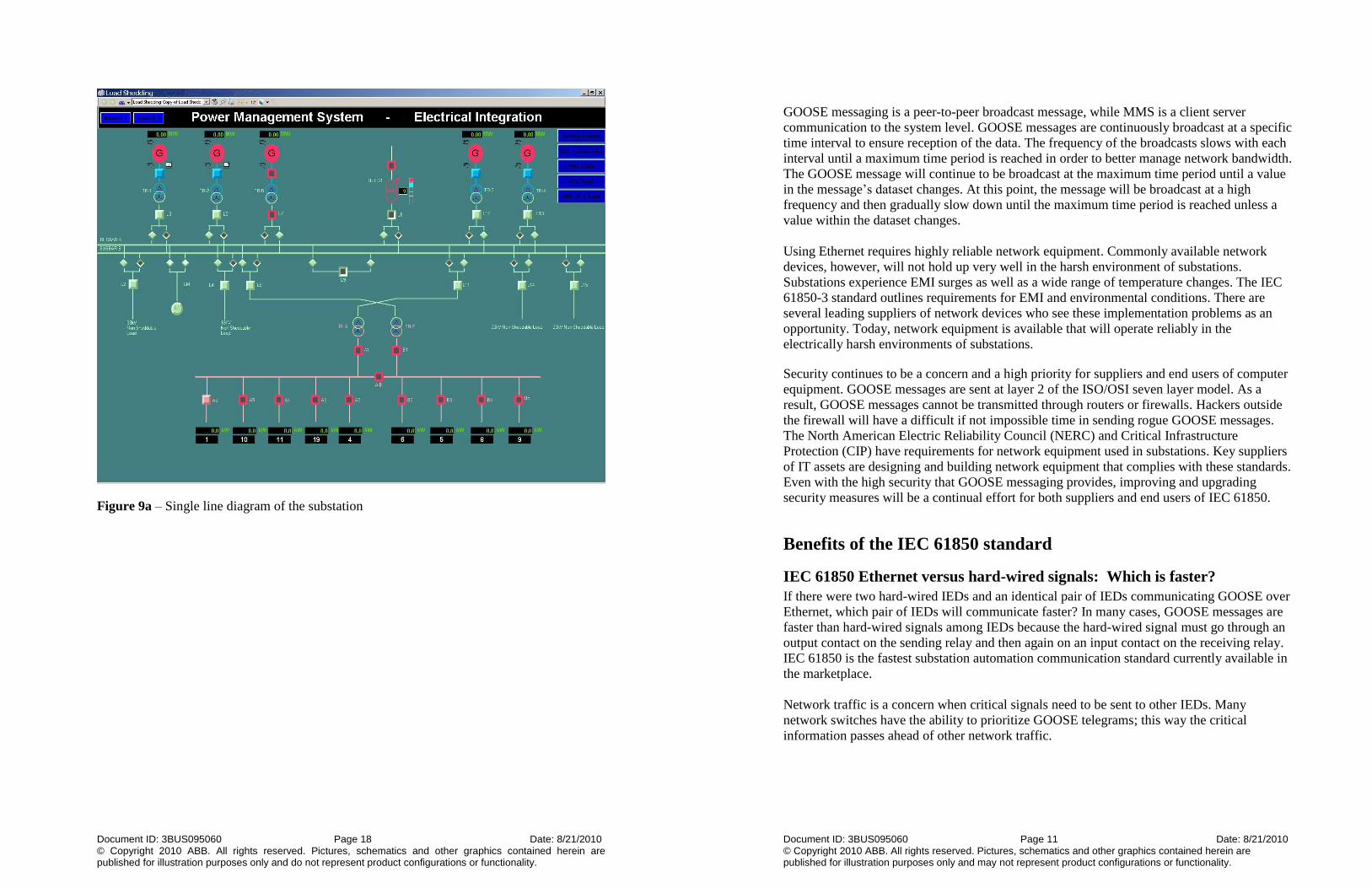
Figure 9a – Single line diagram of the substation
Document ID: 3BUS095060 Page 11 Date: 8/21/2010 © Copyright 2010 ABB. All rights reserved. Pictures, schematics and other graphics contained herein are published for illustration purposes only and may not represent product configurations or functionality.
GOOSE messaging is a peer-to-peer broadcast message, while MMS is a client server
communication to the system level. GOOSE messages are continuously broadcast at a specific
time interval to ensure reception of the data. The frequency of the broadcasts slows with each
interval until a maximum time period is reached in order to better manage network bandwidth.
The GOOSE message will continue to be broadcast at the maximum time period until a value
in the message’s dataset changes. At this point, the message will be broadcast at a high
frequency and then gradually slow down until the maximum time period is reached unless a
value within the dataset changes.
Using Ethernet requires highly reliable network equipment. Commonly available network
devices, however, will not hold up very well in the harsh environment of substations.
Substations experience EMI surges as well as a wide range of temperature changes. The IEC
61850-3 standard outlines requirements for EMI and environmental conditions. There are
several leading suppliers of network devices who see these implementation problems as an
opportunity. Today, network equipment is available that will operate reliably in the
electrically harsh environments of substations.
Security continues to be a concern and a high priority for suppliers and end users of computer
equipment. GOOSE messages are sent at layer 2 of the ISO/OSI seven layer model. As a
result, GOOSE messages cannot be transmitted through routers or firewalls. Hackers outside
the firewall will have a difficult if not impossible time in sending rogue GOOSE messages.
The North American Electric Reliability Council (NERC) and Critical Infrastructure
Protection (CIP) have requirements for network equipment used in substations. Key suppliers
of IT assets are designing and building network equipment that complies with these standards.
Even with the high security that GOOSE messaging provides, improving and upgrading
security measures will be a continual effort for both suppliers and end users of IEC 61850.
Benefits of the IEC 61850 standard
IEC 61850 Ethernet versus hard-wired signals: Which is faster?
If there were two hard-wired IEDs and an identical pair of IEDs communicating GOOSE over
Ethernet, which pair of IEDs will communicate faster? In many cases, GOOSE messages are
faster than hard-wired signals among IEDs because the hard-wired signal must go through an
output contact on the sending relay and then again on an input contact on the receiving relay.
IEC 61850 is the fastest substation automation communication standard currently available in
the marketplace.
Network traffic is a concern when critical signals need to be sent to other IEDs. Many
network switches have the ability to prioritize GOOSE telegrams; this way the critical
information passes ahead of other network traffic.

Document ID: 3BUS095060 Page 12 Date: 8/21/2010 © Copyright 2010 ABB. All rights reserved. Pictures, schematics and other graphics contained herein are published for illustration purposes only and do not represent product configurations or functionality.
IEC 61850 Ethernet versus hard-wired signals: Which is more reliable?
Connectivity among IEDs is automatically supervised by GOOSE. GOOSE sends out a
quality byte with each telegram. If the quality is bad or poor, the application can notify
operators of a problem in the network. Each GOOSE message is repeated continuously until
the data set values change. Each GOOSE message has a counter as well. The recipient of the
GOOSE message can compare the counter value to the last one to see if it has missed a
message and then take appropriate action. Or if the repeating message is not received in a
certain period of time, then the recipient can take action. In either case, the connectivity
failure will be detected. In the case of hard-wired IEDs, detecting a break in the signal wiring
may not be possible.
Low Voltage Integration Although IEC 61850 does not address low voltage equipment, the integration of LV
equipment to the DCS is just as important as integrating MV/HV substation equipment.
One benefit of integrating intelligent LV switchgear to the DCS include shorter time to
complete repairs. With quicker detection of failures and root cause analysis via integrated
asset monitors, technicians will have greater knowledge of the problem and a plan of action
before they go into the plant to make the repairs. Integrating the LV maintenance system to
the DCS allows all plant teams to be informed and become involved in improving plant
performance and uptime. Segregated systems equates to uncoordinated actions and decisions
that can result in inefficiencies and lower production.
A truly integrated system such as ABB’s MNS iS with System 800xA provides continuous
condition maintenance information on the health of the plant’s LV switchgear. The MNS iS
asset monitor provides predictive and proactive condition monitoring. The asset monitor
identifies what the problem is; where the problem is; the severity of the problem; who should
initiate actions (for example, operator, maintenance, and/or engineer); what caused the
problem; and most importantly, what specific action is needed to solve the problem.
Unnecessary maintenance is avoided by changing from a scheduled based maintenance
approach to consumption based maintenance. Consumption based maintenance focuses on
how much the equipment is used and at what power levels. Even if the equipment is used
occasionally but at high power consumption, it may need maintenance sooner than if the
equipment was used more often but at lower power consumption.
Document ID: 3BUS095060 Page 17 Date: 8/21/2010 © Copyright 2010 ABB. All rights reserved. Pictures, schematics and other graphics contained herein are published for illustration purposes only and may not represent product configurations or functionality.
do nothing but to start calling maintenance engineers for help. With an integrated system, the
operator is empowered to take action. Instead of just having access to the mixer’s process
control display, the operator can now call up the substation’s Single Line Diagram Display
(SLD) and check the circuit breaker’s status (Figure 9a). Normally, the SLD is available on
the substation system and is not available to the process control operator. Next, the operator
clicks on the motor’s IED faceplate (Figure 9b) and views the disturbance recording that was
automatically uploaded from the IED (Figure 9c). Information about the health of the IED and
circuit breaker is available from the IED’s asset monitor made available by a click on the
faceplate. See Figure 9d. Here we see that the circuit breaker is taking too long to open.
Another click on the faceplate calls up a remote configuration session with the IED. From
here, the operator can dig deeper into the problem and analyze the information and determine
the root cause. Once the operator’s analysis is complete, he or she can correct the problem or
call the appropriate person to assist. Once the problem has been resolved, the operator can
close the circuit breaker, switch back to the mixer display, and restart the motor. All steps
have been completed in this example from a single operator station.
Instead of stating, “Make your operators smarter”, one could state, “Make your engineers
smarter” or “Make your managers smarter” or “Make your vendors smarter”. No longer will
operator, engineers, and managers have a myopic view of just their individual plant areas.
With an integrated system, all persons involved will learn more about plant operations and
issues and as a result, become more effective in their respective positions.

Document ID: 3BUS095060 Page 16 Date: 8/21/2010 © Copyright 2010 ABB. All rights reserved. Pictures, schematics and other graphics contained herein are published for illustration purposes only and do not represent product configurations or functionality.
Energy efficiency through faster plant startup times
A large amount of energy is spent when starting up a plant. The more quickly and efficiently a
plant is started, the more energy is saved. For example, a power plant can achieve faster start-
up times by replacing the mechanical overspeed bolt trip system with a turbine protection
system integrated with the DCS. After every shutdown, the power plant must test the turbine’s
trip system. A mechanical overspeed bolt trip system test requires the turbine shaft to spin at
110% synchronous speed. The turbine must first be warmed up for a few hours on-line in
order for the shaft to be thermally prepared to operate at 110% of synchronous speed. When
the turbine protection system is integrated with the DCS, it is possible to perform the
overspeed trip test at nearly any turbine shaft speed by simply initiating a trip through the
two-out-of-three trip manifold. In addition, functional testing can be performed at any time,
on-line or off-line, by watching the solenoids activate without actually tripping the turbine.
No time is spent thermally conditioning the turbine for trip testing; thus, startup times are
lower compared to a mechanical overspeed bolt trip system. Removing the need for an
overspeed trip bolt decreases startup time and increases the life of the turbine, as operating
above the shaft design speed prematurely ages the turbine.
An integrated system allows for enhanced energy savings applications such as rotor stress
prediction for steam turbines. The controller-based rotor stress application is now possible
since all of the required inputs are available from the integrated system. Data from the various
integrated components such as vibration, turbine position, and thermal couple inputs, in
conjunction with process data, simplifies the design of the application. The rotor stress
application produces turbine thermal stress information. If the turbine is started improperly,
the shaft can warp. Typically, it takes nine to twelve weeks to straighten a warped turbine
shaft. The goal of the application is to keep stress on the turbine shaft to a minimum while
providing operators with safe acceleration and loading rates. With this information, operators
can start the turbine more quickly. The faster the turbine is started, the more startup energy is
saved, and more revenue is realized from the generation of power.
Make your operators smarter through integration
With traditional multiple system plants, operators make critical decisions in silos. Often they
have a myopic view of the plant, and their knowledge and skill set is limited to only one area.
With an integrated system, operators can collaborate more effectively with other disciplines.
They will have total plant visualization - operators can now see into the plant beyond their
normal process areas. Their capabilities will expand beyond traditional roles and functions. A
DCS process control operator must now understand the effects that substation automation
systems have on the process control areas. Better visibility turns data into actionable
knowledge that operators can use to support smart decisions, made more quickly. By utilizing
the Electrical Integration architecture, operators get out of their silos and into saving money
and increasing uptime throughout the plant.
Consider the following scenario. It is the job of a DCS operator to ensure that a mixer’s
agitator motor is turning and operating at the proper speed. From a DCS process control
display, the operator can start, stop, and change the speed of the motor. Suddenly, the mixer
stops. After repeated unsuccessful attempts to restart the motor, the operator is empowered to
Document ID: 3BUS095060 Page 13 Date: 8/21/2010 © Copyright 2010 ABB. All rights reserved. Pictures, schematics and other graphics contained herein are published for illustration purposes only and may not represent product configurations or functionality.
Benefits of integration
Power generation use case
Introduction
Figure 7 below shows a fully integrated power generation plant system. It is similar to the
generic Electrical Integration diagram shown in Figure 1. The integrated power plant system
is divided into three areas:
1. Turbine Controls System (TCS)
2. Boiler and balance of plant control, also known as Distributed Control System (DCS)
3. Electrical Control System (ECS).
Today’s sophisticated DCS controllers can integrate multiple Fieldbuses into a single
controller providing the end users with a freedom of choice for Fieldbus technology 4
. In the
TCS section, Fieldbus communication interface modules are used to integrate the turbine
controls such as turbine valve position, auto synchronization, turbine position, and vibration
condition monitoring into the controller. This eliminates the need for separate communication
hardware resulting in a simpler design. Once the TCS data is in the controller, diagnostic and
process information is made available to all necessary plant areas such as the DCS and ECS.
One platform to learn equates to shorter training periods for plant personnel including
operators, engineers, planners, and managers. The same controller, I/O modules, and
engineering tools are used in the balance of plant as in the TCS. In addition, fewer spare parts
are required. An integrated system protects assets and can help promote the safety of
personnel while optimizing plant operations and reducing life cycle costs.
NERC and CIP security and compliancy is made easier with an integrated system. A common
audit trail for the entire plant is possible. In addition, only one system will need to be updated
with software security patches. It is easier and cheaper to maintain security on one system
than it is to secure multiple systems.

Document ID: 3BUS095060 Page 14 Date: 8/21/2010 © Copyright 2010 ABB. All rights reserved. Pictures, schematics and other graphics contained herein are published for illustration purposes only and do not represent product configurations or functionality.
Figure 7 – Integrated process and power automation for a power plant system
Energy efficiency with integrated VFDs
Power plant auxiliary system power usage is on the rise. In fact, 7 to 15% of generated power
is used by the power plant’s auxiliary systems5. This number is increasing due to the addition
of anti-pollution systems and an increase in cooling water pumping needs to control thermal
discharge issues. Today, modern plants are still using direct connect motors with throttling
valves to control flow. By replacing them with integrated variable frequency drives (VFDs),
the expected energy savings is substantial. Figure 8 shows a chart of percent power required
versus percent flow. According to the chart, when operating a direct connect motor at 50%
flow, the power required is 68% of what it would be at maximum flow. When using a VFD,
the power consumed is only 22% of maximum power. This equates to 67% less power
consumed when using a VFD versus a direct connect motor.
Document ID: 3BUS095060 Page 15 Date: 8/21/2010 © Copyright 2010 ABB. All rights reserved. Pictures, schematics and other graphics contained herein are published for illustration purposes only and may not represent product configurations or functionality.
Figure 8– Percent power required versus percent flow
5
Energy efficiency through improved visibility into power consumption
Plant electrical information is often difficult to access and view. By taking advantage of an
integrated architecture, critical power data is more readily available. With this critical data,
power usage can be observed, monitored, and studied. It provides better visibility into power
consumption and real-time energy usage and costs. It also allows for easier energy audits and
benchmarking.
An integrated system enables operators to understand and easily access power usage. New
energy savings opportunities can be explored, while existing energy reduction programs can
be enhanced. An integrated system provides a centralized historical data source. Now energy
consumption can be tracked plant-wide from one database. For example, an increase in power
consumption by a unit or an area can indicate equipment malfunction and wear. Without
visibility into power consumption, the problem may go unnoticed which could result in
unexpected downtime plus a preventable increase in energy usage.
Another advantage to an integrated system is immediate visibility of a power event such as
bus transfer, load sheds, or trips from any operator station. The status of critical electrical
equipment can be seen, alerting operators to potential system problems. Information can be
provided via alarm and events lists as well as email and text messaging notifications. Work
orders can automatically be opened to a Computerized Maintenance Management System
(CMMS). Whether it is an electrical glitch, process control problem, or a failing IT asset,
plant operators will have complete visibility and control of the situation.