power upgrading of transmission line by combining ac dc transmission
TRANSCRIPT

POWER UPGRADING OF TRANSMISSION
LINE BY COMBINING AC-DC TRANSMISSION
BY H . GADHIYA, H . BHARADVA, S . SENTA, N . GHINAIYA
GUIDE : PRO.
J.B.SARVAIYA

PROJECT THEMEI. Introduction
II. Background survey
III. Theoretical proof of ac-dc combine transmission
IV. Matlab simulation of ac-dc combine transmission
V. Response of ehv ac transmission
VI. Response of ac-dc combine transmission
VII. Case of study
VIII.Economical proof of ac-dc combine transmission
IX. Advantages & Limitation of ac-dc combine transmission
X. Conclusion

1. INTRODUCTION

1). EHV AC Transmission2). HVDC Transmission3). AC-DC Combine Transmission a). AC-DC 3-phase Single Line Transmission b). AC-DC 3-phase Double Line Transmission

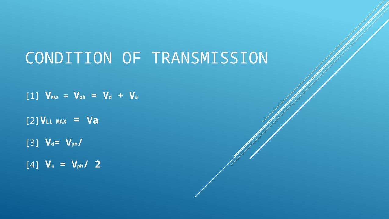
CONDITION OF TRANSMISSION
[1] VMAX = Vph = Vd + Va
[2]VLL MAX = Va
[3] Vd= Vph/
[4] Va = Vph/ 2

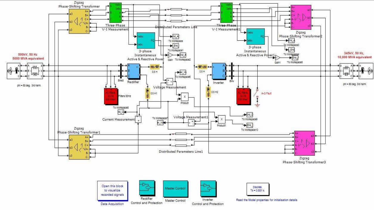
2. MATLAB SIMULATION


3.CASE OF STUDY
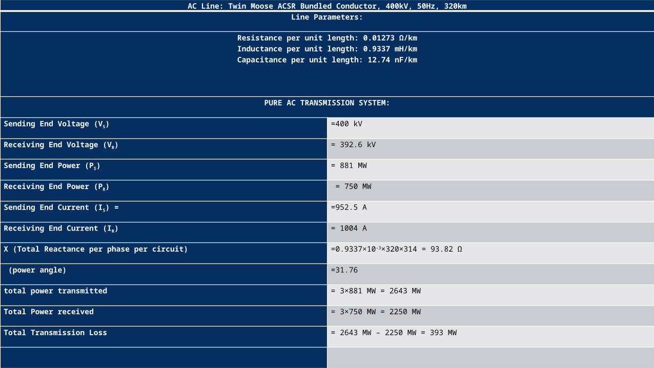
AC Line: Twin Moose ACSR Bundled Conductor, 400kV, 50Hz, 320kmLine Parameters:
Resistance per unit length: 0.01273 Ω/kmInductance per unit length: 0.9337 mH/kmCapacitance per unit length: 12.74 nF/km
PURE AC TRANSMISSION SYSTEM:
Sending End Voltage (VS) =400 kV
Receiving End Voltage (VR) = 392.6 kV
Sending End Power (PS) = 881 MW
Receiving End Power (PR) = 750 MW
Sending End Current (IS) = =952.5 A
Receiving End Current (IR) = 1004 A
X (Total Reactance per phase per circuit) =0.9337×10-3×320×314 = 93.82 Ω
(power angle) =31.76
total power transmitted = 3×881 MW = 2643 MW
Total Power received = 3×750 MW = 2250 MW
Total Transmission Loss = 2643 MW – 2250 MW = 393 MW

SIMULTANEOUS AC-DC POWER TRANSMISSION SYSTEM:
Sending End AC Voltage (VS) = 400 kv
Receiving End AC Voltage (VR) = 392.6 kV
AC Current (Iac) = 2.341 kA
Sending End AC Power (PS) = 1600 MW
Receiving End AC Power (PR) = 1100 MW
Total Reactance per phase per circuit (X) = 93.82 Ω
Rectifier Voltage (Vdr) = 440 kV
Inverter Voltage (Vdi) = 300 kV
DC Link Current (Id) = 1.74 kA
Sending End DC Power = 765.6 MW
Receiving End DC Power = 522 MW
= 70°
Total Power Transmitted = 2×1600 + 765.6 = 3965.6 MW
Total Power Received = 2722 MW
Transmission Loss = 3965.6 MW – 2722 MW= 1243.6MW
Now, dc voltage across one winding = 440/2 = 220 kV.
Induced voltage across secondary winding of transformer = 200 kV
Vdo = 220 kV

So, power factor of the rectifier (cosθr) = 220/271 = 0.812
Similarly for inverter Vdoi = 271 kVVdo = 150 kV
Power factor of the inverter (cosθi) = 150/271 = 0.5535
So, reactive power drawn by the rectifier = 765.6 tanθr = 550.3 MVARReactive power drawn by the inverter = 522 tanθi = 785.45 MVAR
Power Up gradation =
Power transformer in composite AC – DC transmissions - power transmitted in pure
transmission / power transmitted in pure transmission
= [ 2722 – 2250 / 2250 ] Χ 100
= 21 %
4.ECONOMY

ECONOMY OF THE SYSTEM
[1] ECONOMY OF SYSTEM BASED ON COMPARISON
[2] ECONOMY OF SYSTEM BASED ON STRUCTURE

FOR DOUBLE CIRCUIT EHV LINEBase cost of 500 KV double circuit transmission line Rs. 1,78,020,000 Line Multiplier :
(1) Conductor
ACSR (1.0) √ ACSS (1.08) TLS (3.60)(2) Tower Structure:
Lattice (1.0) √ Tabular Steel (1.50)(3) Transmission Length:
Up to 4.82 Km (1.50) 4.82 Km to 16.093 Km (1.20) Above 16.093 Km (1.0) √
Total transmission line cost = [ (base transmission cost)*(conductor multiplier)*(structure multiplier) *(1.6093)*(no of kilometer) ]
Total transmission line cost Rs. 5.696641010
SUB-STATION CAPITAL COSTBase cost of Sub-Station (500 KV) Rs. 148,320,000
LINE & TRANSFORMER POSITION COST & MULTIPLIER (500 KV)
Cost multiplier : Breaker & half multiplier (1.50) Ring bus multiplier (1.0) √Cost per line / transformer position Rs. 173,040,000Transformer cost (Rs. per MVA)
230 / 500 KV Transformer – Rs. 660,000 115 / 500 KV Transformer – Rs. 600,000 √ Transformer cost (Rs. Per MVA) Rs. 600,000
REACTIVE COMPONENTS COST PER MVARShunt reactor Rs. 1,200,000Series reactor Rs. 600,000SVC capital cost Rs. 5,100,000Total substation cost = [ (sub-station base cost)+(line per transformer position base cost)*(no. of line per transformer position)*(CRB or BAAH multiplier)+(transformer cost per MVA)*(transformer MVA rating)+(SVC cost per MVAR)*(require MVARs)+(series capacitor cost per MVAR)*(require MVARs)+(shunt reactor cost per MVAR)*(require MVARs) ]Total substation cost Rs. 839,052,000 x 2 = 1,678,104,000
TOTAL COSTTotal cost Rs. 5.86445041010

HVDC TRANSMISSION LINE
500 KV HVDC bidirectional pole line (per Km) Rs. 89,040,000
TOTAL COST OF TRANSMISSION LINE
Total cost of transmission line Rs. 2.84928X10¹⁰
SUB-STATION CAPITAL COST
Converter terminal (include DC switching station equipment)
Rs. 3,850,000,000
Reactive support (synchronous condensers, SVCs, etc)
Rs. 2,100,000,000
AC switch yard Rs. 280,000,000
COST OF SUB-STATION
Cost of sub-station Rs. 6,230,000,000 x 2 = 1.246 x 10¹⁰
TOTAL COST
Total cost Rs. 3.47228 x 10¹⁰

COMBINE HVDC-HVAC
SUB-STATION COSTSub-Station cost Rs. 6,230,000,000 x 2 = 1.246 x 10¹⁰
COST OF ZIG-ZAG TRANSFORMER (125)
Cost of zig-zag transformer per MVA (Rs. Per MVA) Rs. 78,000
Cost of 4 zig-zag transformer (Rs. Per MVA) Rs. 78,000 x 4 = 312,000
Total cost of four zig-zag transformer Rs. 390,000,000
TOTAL COST
Total cost Rs. 1.285 x 10¹⁰

5.CONCLUSION

ADVANTAGES OF
SYSTEM
(1) The feasibility to convert ac transmission line to a composite ac–dc line has been demonstrated.
(2) For the particular system studied, there is substantial increase (about 21.45%) in the load ability of the
line.
(3) The line is loaded to its thermal limit with the superimposed dc current.
(4) The dc power flow does not impose any stability problem.
(5) Dc current regulator may modulate ac power flow.
(6) There is no need for any modification in the size of conductors, insulator strings, and towers structure of
the original line.
(7) The optimum values of ac and dc voltage components of the converted composite line are ½ and 1/√2
times the ac voltage before conversion, respectively.

LIMITATION
(1) There Is Certain Limit Of Power Upgrading Of Transmission Line, So We Can Not Apply This Basic
Scheme Where New Unit Has More Power Capacity Then Limit Of Power Upgrading Of Transmission Line.
(2) The Combine HVDC-HVAC Transmission Line Is Very Complicated.
(3) There Is Necessity Of Double Circuit Long Extra High Voltage AC Transmission Line In Running Power
Generating Station.
(4) We Cannot Transfer The Power By This Basic Scheme Where Double Circuit EHV Line Not Going From
The Power Generating Station.

APPLICATION
(1) ADDITION OF GENERATION UNIT
(2) SOLAR GENERATION UNIT


CONCLUSION
For the particular system under study, the power up gradation of the line is observed to be twenty one
percent with the simultaneous ac-dc power flow. Maximum power up gradation is obtained at a
transmission angle of 60º. The line is loaded to its thermal limit with the superimposed dc current. The dc
power flows independent of the ac power in the transmission line.
REFERENCES
PAPERS:-
[1] “Upgradation Of Power Flow In EHV AC Transmission” International Journal Of Scientific Engineering And Technology By
K.K.Vasishta Kumar, K.Sathish Kumar.
[2] “Power Upgrading Of Transmission Line By Combining AC-DC Transmission”, Swarnandhra College Of Engineering
Technology Narsapur By Jarupula Somlal.
[3] “Power System Stability Enhancement By Simultaneous AC-DC Power Transmission” International Journal Of Advanced
Research In Electrical, Electronics And Instrumentation Engineering Vol. 2, Issue 5, May 2013 By Abhishek Chaturvedi, V. K.
Tripathi, T Vijay Muni, Neeraj Singh.
[4] “Power Tapping Of Upgrade Transmission Line By Using Composite Ac-dc Power Transmission Lines”
International Journal Of Engineering Research And Development By CH.Veeraiah, Y.Rambabu, V.K.R.Mohan Rao.

BOOKS:-
[1] D P Kothari And I J Nagrath “MODERN POWER SYSTEM ANALYSIS” FNAE Fnasc,
Fellow-ieee Director General, Raisoni Group Of Institutions, Nagpur.
[2] Tim Mason- Project Manager, Trevor Curry And Dan Wilson, “CAPITAL COSTS FOR
TRANSMISSION AND SUBSTATION” Western Electricity Coordinating Council.
[3] Roberto Rudervall, J.P. Charpentier And Raghuveer Sharma, “HIGH VOLTAGE DIRECT
CURRENT (HVDC)TRANSMISSION SYSTEMS” Technology Review Paper, Presented At Energy
Week 2000, Washington, D.C, USA, March 7-8, 2000.

THANK YOU