powerbox industrial line pfb600w-110s series … · 6.9 test set-up p13 6.10 output voltage...
TRANSCRIPT
1www.prbx.com
Table of Contents1. Introduction P12. DC/DC converter features P13. Electrical block diagram P24. Technical specification P35. Main features and functions P65.1 Operating temperature range P65.2 Output voltage adjustment P65.3 Over current protection P65.4 Output over voltage protection P65.5 Remote On/Off P65.6 UVLO & OVLO (under/over voltage lock out) P65.7 Over temperature range P66. Applications P76.1 Recommended layout, PCB footprint and soldering information P76.2 Connection for standard use P76.3 Input capacitance at the power module P86.4 Convection requirements for cooling P86.5 Thermal considerations P86.6 Power de-rating P96.7 Full brick heat sinks P106.8 Efficiency VS load P126.9 Test set-up P136.10 Output voltage adjustment P136.11 Output remote sensing P146.12 Output ripple and noise P156.13 Output capacitance P156.14 On/Off control P156.15 IOG signal P166.16 Auxiliary power for output signal P166.17 Paralle operation P167. Safety & EMC P177.1 Input fusing and safety considerations P177.2 EMC considerations P187.3 Suggested configuration for RIA12 surge test P238. Part number P249. Mechanical specifications P249.1 Mechanical outline diagrams P24
1. IntroductionThe PFB600W-110S series of DC/DC converters offers 600 watts of output power @ single output voltages of 12, 24, 28, 48VDC with industry standard full-brick. It has a wide (4:1) input voltage range of 43 to 160VDC (110VDC nominal) and 2250VDC basic isolation.High efficiency up to 88%, allowing case operating temperature range of –40°C to 100°C. An optional heat sink is available to extend the full power range of the unit. Low no load power consumption (25mA), an ideal solution for energy critical systems. Compliant with EN50155, EN45545, EN50121-3-2. The standard control functions include remote on/off (positive or negative) and +10%, -40% adjustable output voltage. Fully protected against input UVLO (under voltage lock out), output over-current, output over-voltage and over- temperature and continuous short circuit conditions. PFB600W-110S series is designed primarily for common railway applications of 72V, 96V, 110V nominal voltage and also suitable for distributed power architectures, telecommunications, battery operated equipment and industrial applications. 2. DC/DC Converter Features600W isolated outputEfficiency to 88%Regulated outputIsolated remote ON/OFFOver temperature protectionOver voltage/current protectionContinuous short circuit protectionFull-brick size meet industry standardMeet EN50155 with external circuitsShock & vibration meet EN50155 (EN61373)Meet UL60950-1 2nd (basic insulation)
POWERBOX Industrial LinePFB600W-110S Series600W Single OutputDC/DC ConverterManual V2

2www.prbx.com
POWERBOX Industrial LinePFB600W-110S Series600W Single OutputDC/DC ConverterManual V2
+VIN
-VIN
+ON/OFF
-ON/OFF
+VOUT
-VOUT
+SENSE
-SENSE
TRIM
AUX
IOC
PC/NC
3. Electrical Block Diagram
3www.prbx.com
POWERBOX Industrial LinePFB600W-110S Series600W Single OutputDC/DC ConverterManual V2
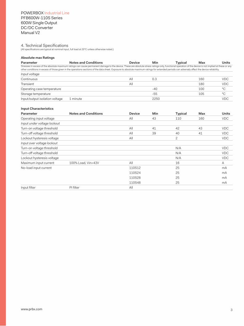
4. Technical Specifications(All specifications are typical at nominal input, full load at 25°C unless otherwise noted.)
Absolute max Ratings Parameter Notes and Conditions Device Min Typical Max UnitsStresses in excess of the absolute maximum ratings can cause permanent damage to the device. These are absolute stress ratings only, functional operation of the device is not implied at these or any other conditions in excess of those given in the operations sections of the data sheet. Exposure to absolute maximum ratings for extended periods can adversely affect the device reliability.
Input voltageContinuous All 0.3 160 VDCTransient All 180 VDCOperating case temperature -40 100 °CStorage temperature -55 105 °CInput/output isolation voltage 1 minute 2250 VDC Input Characteristics Parameter Notes and Conditions Device Min Typical Max UnitsOperating input voltage All 43 110 160 VDCInput under voltage lockoutTurn-on voltage threshold All 41 42 43 VDCTurn-off voltage threshold All 39 40 41 VDCLockout hysteresis voltage All 2 VDCInput over voltage lockoutTurn-on voltage threshold N/A VDCTurn-off voltage threshold N/A VDCLockout hysteresis voltage N/A VDCMaximum input current 100% Load, Vin=43V All 16 ANo-load input current 110S12 25 mA 110S24 25 mA 110S28 25 mA 110S48 25 mAInput filter PI filter All

4www.prbx.com
POWERBOX Industrial LinePFB600W-110S Series600W Single OutputDC/DC ConverterManual V2
Output Characteristics Parameter Notes and Conditions Device Min Typical Max UnitsOutput voltage set point Vin=Nominal Vin, Io = Io_max, Tc=25°C Vo=12V 11.88 12.00 12.12 VDC Vo=24V 23.76 24.00 24.24 VDC Vo=28V 27.72 28.00 28.28 VDC Vo=48V 47.52 48.00 48.48 VDCOutput voltage regulationLoad regulation Io=Io_min to Io_max All ±0.5 %Line regulation Vin=low line to high line All ±0.2 %Temperature coefficient TC=-40°C to 100°C All ±0.03 %/°COutput voltage ripple and noisePeak-to-Peak 20MHz bandwidth, full load, 10uF 110S12 120 mV tantalum and 1.0uF ceramic 110S24 240 mV capacitors (48V: 10uF aluminum 110S28 280 mV and 1.0uF ceramic capacitors) 110S48 480 mVRMS 20MHz bandwidth, full load, 10uF 110S12 60 mV tantalum and 1.0uF ceramic capacitors 110S24 100 mV (48V: 10uF aluminum and 1.0uF 110S28 100 mV ceramic capacitors) 110S48 200 mVOperating output current range 110S12 0 50 A 110S24 0 25 A 110S28 0 21.4 A 110S48 0 12.5 AOutput DC current limit inception Output voltage=90% nominal ALL 105 140 %Power good signal(IOC) Vout ready: low level, sink current All 20 mA Vout not ready: open drain output, All 50 V applied voltage Output capacitance Full load (resistive) 110S12 470 10000 uF 110S24 470 10000 uF 110S28 470 10000 uF 110S48 470 10000 uF Dynamic Characteristics Parameter Notes and Conditions Device Min Typical Max UnitsOutput voltage current transientStep change in output current di/dt=0.1A/us, load change from 75% to 100% to 75% of Io,max All ±3 ±5 %Setting time (within 1% Vout nom) di/dt=0.1A/us All 500 usTurn-on delay and rise timeTurn-on delay time, from On/Off control Von/off to 10%Vo_set All 75 msTurn-on delay time, from input Vin_min to 10%Vo_set All 135 250 msOutput voltage rise time 10%Vo_set to 90%Vo_set All 25 50 ms Efficiency Parameter Notes and Conditions Device Min Typical Max Units100% Load 110S12 87 % 110S24 88 % 110S28 88 % 110S48 88 %

5www.prbx.com
POWERBOX Industrial LinePFB600W-110S Series600W Single OutputDC/DC ConverterManual V2
Isolation Characteristics Parameter Notes and Conditions Device Min Typical Max UnitsIsolation voltage 1 minute; input/output, input/case, All 2250 VDC input/remote, output/remote 1 minute; output/case All 1500 VDCIsolation resistance All 10 MΩIsolation capacitance All 4000 pF Feature Characteristics Parameter Notes and Conditions Device Min Typical Max UnitsSwitching Frequency All 250 KHzON/OFF control negative remote On/Off logicLogic low (module off) All 0 0.01 mALogic high (module on) All 1.0 10 mAON/OFF control positive remote On/Off logicLogic high (module off) All 1.0 10 mALogic high (module on) All 0 0.01 mAAuxiliary output voltage All 7 10 13 VAuxiliary output current All 20 mALoad share accuracy (50%- 100% load) All -10 +10 %Off converter input current Shutdown input idle current All 50 mAOutput voltage trim range Pout=max rated power All 60 110 %Output over voltage protection All 115 125 140 %Over-temperature cshutdown All 110 °COver temperature recovery Aluminum baseplate temperature All 90 °C General Specifications Parameter Notes and Conditions Device Min Typical Max UnitsMTBF Io=100% of Io_max: Ta=25°C per MIL-HDBK-217F 450 KhoursWeight All 220 gramsCase material Plastic, DAPBaseplate material AluminumPotting material UL 94V-0Pin material Base: Copper Plating: Nickel with matte tinShock/vibration MIL-STD-810F / EN61373Humidity 95% RH max. Non condensingAltitude 2000m Operating altitude , 12000m transport altitudeThermal shock MIL-STD-810FEMI Meets EN50155(EN50121-3-2) with external input filter, see 7.2ESD EN61000-4-2 Air ±8kV, Contact ±6kV Perf. Criteria BRadiated immunity EN61000-4-3 80~1000MHz, 20V/m Perf. Criteria AFast transient EN61000-4-4 On power input port, ±2kV, external input capacitor required, see 7.1 Perf. Criteria ASurge EN61000-4-5 Line to earth, ±2kV, Line to line, ±1kV Perf. Criteria BConducted immunity EN61000-4-6 0.15~80MHz, 10V Perf. Criteria AInterruptions of Voltage Supply EN50155 Class S2: 10ms Interruptions Perf. Criteria BSupply Change Over EN50155 Class C2: During a supply break of 30 ms Perf. Criteria B

6www.prbx.com
POWERBOX Industrial LinePFB600W-110S Series600W Single OutputDC/DC ConverterManual V2
5. Main Features and Functions 5.1 Operating Temperature RangeThe PFB600W-110S series converters can be operat- ed within a wide case temperature range of -40°C to 100°C. Consideration must be given to the de-rating curves when ascertaining maximum power that can be drawn from the converter. The maximum power drawn from full brick models is influenced by usual factors, such as:• Input voltage range• Output load current• Forced air or natural convection• Heat sink optional 5.2 Output Voltage AdjustmentSection 6.10 describes in detail how to trim the output voltage with respect to its set point. The output voltage on all models is adjustable within the range of 60% to 110%.
5.3 Over Current ProtectionThe converter is protected against over current or short circuit conditions. At the instance of current-limit inception, the module enters a constant current mode of operation. While the fault condition exists, the module will remain in this constant current mode, and can remain in this mode until the fault is cleared. The unit operates normally once the output current is reduced back into its specified range.
5.4 Output Over Voltage ProtectionThe converter is protected against output over voltage conditions. When the output voltage is higher than the specified range, the module enters a hiccup mode of operation.
5.5 Remote On/OffThe On/Off input pins permit the user to turn the power module on or off via a system signal from the primary side or the secondary side. Two remote on/off options are available. Negative logic turns the module on as long as a current (1-10mA) is flowing between +on/off and –on/off and inactive when no current is flowing. Positive logic turns the module off as long as a current (1-10mA) is flowing between +on/off and – on/off and active when no current is flowing. See 6.14.
5.6 UVLO&OVLO (Under/Over Voltage Lock Out)Input under voltage lockout is standard on the PHB600W-110S unit. The unit will shut down when the input voltage drops below a threshold, and the unit will operate when the input voltage goes above the upper threshold.
5.7 Over Temperature ProtectionThese modules have an over temperature protection circuit to safeguard against thermal damage. Shutdown occurs with the maximum case reference temperature is exceeded. The module will restart when the case temperature falls below over temperature recovery threshold. Please measure case temperature of the center part of aluminum baseplate.

7www.prbx.com
POWERBOX Industrial LinePFB600W-110S Series600W Single OutputDC/DC ConverterManual V2
Recommend PCB Pad layout
6. Applications 6.1 Recommended Layout, PCB Footprint and Soldering InformationThe system designer or end user must ensure that metal and other components in the vicinity of the converter meet the spacing requirements for which the system is approved. Low resistance and inductance PCB layout traces are the norm and should be used where possible. Due consideration must also be given to proper low impedance tracks between power module, input and output grounds. Clean the soldered side of the module with a brush, Prevent liquid from getting into the module. Do not clean by soaking the module into liquid. Do not allow solvent to come in contact with product labels or resin case as this may changed the color of the resin case or cause deletion of the letters printed on the product label. After cleaning, dry the modules well.The suggested soldering iron is 450°C for up to 5 seconds(less than 50W). Furthermore, the recommended soldering profile and PCB layout are shown below.
Lead Free Wave Soldering Profile
050
100150200250300
Time (Seconds)
Tem
pera
ture
(°C)
0 5 100 150
6.2 Connection for Standard UseThe connection for standard use is shown below. An external input capacitor (C1) 220uF for all models is recommended to reduce input ripple voltage. External output capacitors (C2, C3) are recommended to reduce output ripple and noise, 470uF aluminum and 1uF ceramic capacitor. The PFB600W-110S series converters have no internal fuse. In order to achieve maximum safety and system protection, always use an input line fuse. We recommended a 20A fast acting fuse for all models. It is recommended that the circuit have a transient voltage suppressor diode (TVS) across the input terminal to protect the unit against surge or spike voltage and input reverse voltage (as shown).
Symbol Component ReferenceF1 Input fuse Section 7.1C1 External capacitor on input side NoteC2,C3 External capacitor on the output side Section 6.12/6.13Noise Filter External input noise filter Section 7.2Remote On/Off External Remote On/Off control Section 6.14Trim External output voltage adjustment Section 6.10Heat sink External heat sink Section 6.4/6.5/6.6/6.7+Sense/-Sense -- Section 6.11
Note: If the impedance of input line is high, C1 capacitance must be more than above. Use more than two recommended capacitor above in parallel when ambient temperature becomes lower than -20°C.

8www.prbx.com
POWERBOX Industrial LinePFB600W-110S Series600W Single OutputDC/DC ConverterManual V2
6.3 Input Capacitance at the Power ModuleThe converters must be connected to low AC source impedance. To avoid problems with loop stability source inductance should be low. Also, the input capacitors (Cin) should be placed close to the converter input pins to de- couple distribution inductance. However, the external input capacitors are chosen for suitable ripple handling capability. Low ESR capacitors are good choice. Circuit as shown as below represents typical measurement methods for reflected ripple current. C1 and L1 simulate a typical DC source impedance. The input reflected-ripple current is measured by current probe to oscilloscope with a simulated source Inductance (L1).
6.4 Convection Requirements for CoolingTo predict the approximate cooling needed for the half brick module, refer to the power derating curves in section 6.6. These derating curves are approximations of the ambient temperatures and airflows required to keep the power module temperature below its maximum rating. Once the module is assembled in the actual system, the module’s temperature should be monitored to ensure it does not exceed 100°C as measured at the center of the top of the case (thus verifying proper cooling)
6.5 Thermal ConsiderationsThe power module operates in a variety of thermal environments; however, sufficient cooling should be provided to help ensure reliable operation of the unit. Heat is removed by conduction, convection, and radiation to the surrounding environment. The test data is presented in section 6.6. The power output of the module should not be allowed to exceed rated power (Vo_set x Io_max)
C1 Cin
L1
To Oscilloscope
+Vin
-Vin
+Vo
-Vo
R-LoadVin
+
-
L1: 12uH C1: 220uF ESR<0.14ohm @100KHz Cin: 220uF ESR<0.14ohm @100KHz

9www.prbx.com
POWERBOX Industrial LinePFB600W-110S Series600W Single OutputDC/DC ConverterManual V2
6.6 Power De-ratingThe operating case temperature range of PFB600W-110 series is -40°C to +100°C. When operating the PFB600W-110S series, proper de-rating or cooling is needed. The maximum case temperature under any operating condition should not be exceeded 100°C.
The following curve is the de-rating curve of PFB600 series without heat sink.
ExampleWhat is the minimum airflow necessary for a PFB600W-110S12 operating at nominal line, an output current of 30A, and a maximum ambient temperature of 40°C.
Solution: Given: Vin=110Vdc Vo=12Vdc Io=30A
Determine power dissipation (Pd): Pd =Pi-Po=Po(1-h)/h Pd =12×30×(1-0.87)/0.87=54Watts
Determine airflow: Given: Pd =54W and Ta=30°C
Check above power de-rating curve: minimum airflow= 800 ft./min.
Verifying: The maximum temperature rise: DT = Pd × Rca=54×1.23=66.42°CThe maximum case temperature: Tc=Ta+DT=96.42°C <100°C
Where:The Rca is thermal resistance from case to ambience.The Ta is ambient temperature and the Tc is case temperature.
Chart of thermal resistance vs air flow.
AIR FLOW RATE TYPICAL RcaNatural Convection 20ft./min. (0.1m/s) 3.82°C /W100 ft./min. (0.5m/s) 3.23°C /W200 ft./min. (1.0m/s) 2.71°C/W300 ft./min. (1.5m/s) 2.28°C/W400 ft./min. (2.0m/s) 1.92°C/W500 ft./min. (2.5m/s) 1.68°C/W600 ft./min. (3.0m/s) 1.50°C/W700 ft./min. (3.5m/s) 1.35°C/W800 ft./min. (4.0m/s) 1.23°C/W
Power Dissipated vs Ambient Temperature and Air Flow
0
10
20
30
40
50
60
70
80
90
0 10 20 30 40 50 60 70 80 90 100Ambient Temperature ,Ta(Deg. C)
Pow
er D
issp
ated
,Pd(
Wat
ts)
Natural Convection 20 ./m in. (0.1 m /s)100 ./m in. (0.5 m /s)
200 ./m in. (1.0 m /s)
300 ./m in. (1.5 m /s)
400 ./m in. (2.0 m /s)
500 ./m in. (2.5 m /s)
600 ./m in. (3.0 m /s)
700 ./m in. (3.5 m /s)
800 ./m in. (4.0 m /s)
AIR FLOW RATE TYPICAL RcaNatural Convection 20ft./min. (0.1m/s) 2.4°C/W100 ft./min. (0.5m/s) 1.76°C/W200 ft./min. (1.0m/s) 1.17°C/W300 ft./min. (1.5m/s) 1.00°C/W400 ft./min. (2.0m/s) 0.83°C/W
Power Diss ipat ed v s Am bie nt Temperatu re with h eat s ink M-B01 2
0
10
20
30
40
50
60
70
80
90
0 1 0 20 30 4 0 50 60 70 80 90 1 00Ambient T em perature ,Ta(Deg. C)
Pow
er D
issp
ated
,Pd(
Wat
ts)
Natu ral C onvectio n 20 ./m in . (0.1 m/s)
10 0 . /min. (0. 5 m /s)
20 0 . /min. (1. 0 m /s)
30 0 . /min. (1. 5 m /s)
40 0 . /min. (2. 0 m /s)
Forced Convection Power De-rating with Heat Sink M-B012
The following curve is the de-rating curve of PFB600W-110S12 series with heat sink M-B012.
ExampleWhat is the minimum airflow necessary for a PFB600W-110S12 operating at nominal line, an output current of 37A, and a maximum ambient temperature of 40°C.
Solution: Given: Vin=48Vdc, Vo=12Vdc, Io=37A
Determine Power dissipation (Pd): Pd=Pi-Po=Po(1-h)/ h Pd=12x37x(1-0.87)/0.87=66.4Watts (Chart of thermal resistance vs air flow)
Determine airflow: Given: Pd=66.4W and Ta=40°C
Check above Power de-rating curve: minimum airflow= 400 ft./min.
Verifying:The maximum temperature rise DT = Pd × Rca=66.4×0.83=55.1°C The maximum case temperature Tc=Ta+DT=95.1°C <100°C
Where:The Rca is thermal resistance from case to ambience.The Ta is ambient temperature and the Tc is case temperature.

10www.prbx.com
POWERBOX Industrial LinePFB600W-110S Series600W Single OutputDC/DC ConverterManual V2
6.7 Full Brick Heat Sinks
Heat Sink (Clear Mounting Inserts f 3.3mm Through): 116.8*61*25.4(M-B012) (G6620090204)Thermal PAD: SR60*115.8*0.23 (G6135013070)Screw: M3*20L (G75A1300052)Nut: NH+WOM3*P0.5N(G75A2440392)
Heat Sink (Mounting Inserts M3*0.5 Through): 116.8*61*25.4(M-C997) (G6620980201)Thermal PAD: SR60*115.8*0.23 (G6135013070)Screw: M3*20L (G75A1300052)Washer: WS3.2N (G75A47A0752)
AIR FLOW RATE TYPICAL RcaNatural Convection 20ft./min. (0.1m/s) 2.4°C/W100 ft./min. (0.5m/s) 1.76°C/W200 ft./min. (1.0m/s) 1.17°C/W300 ft./min. (1.5m/s) 1.00°C/W400 ft./min. (2.0m/s) 0.83°C/W
Heat-sink M-B012All Dimension In mmLongitudinal Fins
4-R0.28 10-R0.4
3261
50.8
±0.1
1.8
2.1
88
9.6
4- 3.3
2-R0.8
0.54.2
90°
0.30
106.7±0.1
116.8
5.1
1.4
-0.1
+0
89.
68
2-R0.9
5.05
14.5
+0-0.1
25.4
2.7
5.4
6-R1.05
Heat-sink M-C997All Dimension In mmLongitudinal Fins
116.8±0.3
106.7±0.2 5.055.1
50.8±0
.261
.0±0
.5
2.1
1.4
4-M3*0.5
25.4
9.6
8.0
8.0
8.0
8.0
8.0
9.6
5.4
2.72-R0.9
6-R1.05
4-R0.2
10-R0.4
2-R0.84.2
0.5
90°
0.3
C0.3C0.3

11www.prbx.com
POWERBOX Industrial LinePFB600W-110S Series600W Single OutputDC/DC ConverterManual V2
Full Brick Heat Sink Assembly
Screw
Thermal Pad
Heatsink
Screw nut
Heat Sink: M-B012 Thermal PAD: SR60*115.8*0.23 (G6135013070)Screw: M3*20L (G75A1300052)Nut: NH+WOM3*P0.5N(G75A2440392)
Screw
Washer
Thermal Pad
Heatsink
Heat Sink: M-C997Thermal PAD : SR60*115.8*0.23 (G6135013070)Screw : M3*20 L (G75A1300052)Washer: WS3.2N (G75A47A0752)

12www.prbx.com
POWERBOX Industrial LinePFB600W-110S Series600W Single OutputDC/DC ConverterManual V2
6.8 Efficiency VS. Load

13www.prbx.com
POWERBOX Industrial LinePFB600W-110S Series600W Single OutputDC/DC ConverterManual V2
6.9 Test Set-UpThe basic test set-up to measure parameters such as efficiency and load regulation is shown below. When testing the modules under any transient conditions please ensure that the transient response of the source is sufficient to power the equipment under test. we can calculate:• Efficiency• Load regulation and line regulation.
The value of efficiency is defined as:
Where:Vo is output voltage, Io is output current, Vin is input voltage, Iin is input current.
The value of load regulation is defined as:
Where:VFL is the output voltage at full load VNL is the output voltage at no load
The value of line regulation is defined as:
Where: VHL is the output voltage of maximum input voltage at full load. VLL is the output voltage of minimum input voltage at full load.
PFB600W-110S Series Test setup
Recommend C1and C2 Value C1: 220uF/100VC2: 470uF/100V.
6.10 Output Voltage AdjustmentThe Trim input permits the user to adjust the output voltage up or down according to the trim range specification (60% to 110% of nominal output). This is accomplished by connecting an external resistor between the +Vout and +Sense pin for trim up and between the TRIM and –Sense pin for trim down, see Figure.
Output voltage trim circuit configuration
The Trim pin should be left open if trimming is not being used. The output voltage can be determined by the following equations:
Unit: KΩVo: Nominal Output VoltageRecommend Rt=6.8KΩ
For example, to trim-up the output voltage of 24V module (PFB600W-110S24) by 5% to 25.2V, to trim- down by 20% to 19.2V.
The value Rtrim_up is calculated as follows: Rt=6.8KΩ, Vf=0.525V.
The value of Rtrim_down defined as:
η = Vo × Io Vin × Iin
×100%
Load.reg = VFL −VNL
×100% VNL
PFB600 Series
Line.reg = VHL −VLL
×100% VLL
PFB600 Series
Rt × 33
Vf =
1.24 × (
7.68 +
) Rt + 33 Rt × 33
Rt + 33 Vout = (Vo + VR) × Vf
= 0.525
6.8 × 33
Vf =
1.24 × (
7.68 +
) 6.8 + 33 6.8 × 33
6.8 + 33 25.2 = (24 + VR) × 0.525, VR = 24ΚΩ
= 0.525
19.2 = (24 + VR) × 0.525, VR = 12.57 KΩ

14www.prbx.com
POWERBOX Industrial LinePFB600W-110S Series600W Single OutputDC/DC ConverterManual V2
The typical value of Rtrim_up
12V 24V 28V 48VTrim up % Rtrim_up (KΩ)1% 0.049 0.106 0.272 0.1962% 0.168 0.345 0.55 0.6733% 0.288 0.583 0.829 1.154% 0.407 0.822 1.107 1.6275% 0.526 1.061 1.385 2.1046% 0.645 1.299 1.664 2.5827% 0.765 1.538 1.942 3.0598% 0.884 1.776 2.221 3.5369% 1.003 2.015 2.499 4.01310% 1.123 2.253 2.777 4.49
The typical value of Rtrim_down
12V 24V 28V 48VTrim down % Rtrim_down (KΩ)1% 387.92 396.61 603.07 87.922% 235.74 238.95 301.84 35.743% 168.34 169.98 199.92 68.344% 130.30 131.30 148.68 30.305% 105.88 106.54 117.84 05.886% 88.87 89.34 97.24 88.877% 76.34 76.69 82.50 76.348% 66.73 67.00 71.44 66.739% 59.12 59.33 62.83 59.1210% 52.95 53.12 55.94 52.9511% 47.84 47.99 50.30 47.8412% 43.55 43.67 45.60 43.5513% 39.88 39.99 41.62 39.8814% 36.72 36.81 38.21 36.7215% 33.97 34.04 35.25 33.9716% 31.54 31.61 32.66 31.5417% 29.40 29.46 30.38 29.4018% 27.48 27.53 28.35 27.4819% 25.76 25.81 26.53 25.7620% 24.21 24.25 24.89 24.2121% 22.80 22.83 23.41 22.8022% 21.51 21.54 22.07 21.5123% 20.34 20.37 20.84 20.3424% 19.26 19.28 19.71 19.2625% 18.26 18.28 18.67 18.2626% 17.34 17.36 17.72 17.3427% 16.48 16.50 16.83 16.4828% 15.69 15.71 16.01 15.6929% 14.95 14.97 15.24 14.9530% 14.26 14.27 14.53 14.2631% 13.61 13.62 13.86 13.6132% 13.00 13.01 13.23 13.0033% 12.43 12.44 12.64 12.4334% 11.89 11.90 12.09 11.8935% 11.38 11.39 11.56 11.3836% 10.90 10.91 11.07 10.9037% 10.44 10.45 10.60 10.4438% 10.01 10.02 10.16 10.0139% 9.599 9.608 9.739 9.59940% 9.209 9.217 9.34 9.209
The output voltage can also be adjustment by using external DC voltage
Output voltage = TRIM terminal voltage * Nominal output voltage
6.11 Output Remote SensingThe PFB600W-110S SERIES converter has the capability to remotely sense both lines of its output. This feature moves the effective output voltage regulation point from the output of the unit to the point of connection of the remote sense pins. This feature automatically adjusts the real output voltage of the PFB600W-110S series in order to compensate for voltage drops in distribution and maintain a regulated voltage at the point of load. The remote-sense voltage range is:[(+Vout) - (-Vout)] – [(+Sense) – (-Sense)] < 10% of Vo_nominalWhen remote sense is in use, the sense should be connected by twisted-pair wire or shield wire. If the sensing patterns short, heave current flows and the pattern may be damaged. Output voltage might become unstable because of impedance of wiring and load condition when length of wire is exceeding 400mm. This is shown in the schematic below.

15www.prbx.com
POWERBOX Industrial LinePFB600W-110S Series600W Single OutputDC/DC ConverterManual V2
If the remote sense feature is not to be used, the sense pins should be connected locally. The +Sense pin should be connected to the +Vout pin at the module and the -Sense pin should be connected to the -Vout pin at the module. Wire between +Sense and +Vout and between -Sense and –Vout as short as possible. Loop wiring should be avoided.
The converter might become unstable by noise coming from poor wiring. This is shown in the schematic below.
Note: Although the output voltage can be varied (increased or decreased) by both remote sense and trim, the maximum variation for the output voltage is the larger of the two values not the sum of the values. The output power delivered by the module is defined as the voltage at the output terminals multiplied by the output current. Using remote sense and trim can cause the output voltage to increase and consequently increase the power output of the module if output current remains unchanged. Always ensure that the output power of the module remains at or below the maximum rated power. Also be aware that if Vo.set is below nominal value, Pout.max will also decrease accordingly because Io.max is an absolute limit. Thus, Pout.max = Vo.set x Io.max is also an absolute limit. 6.12 Output Ripple and NoiseOutput ripple and noise measured with 10uF tantalum capacitor(48Vo:10uF aluminum capacitor) and 1uF ceramic capacitor across output. A 20 MHz bandwidth oscilloscope is normally used for the measurement. The conventional ground clip on an oscilloscope probe should never be used in this kind of measurement. This clip, when placed in a field of radiated high frequency energy, acts as an antenna or inductive pickup loop, creating an extraneous voltage that is not part of the output noise of the converter.
Another method is shown in below, in case of coaxial- cable/BNC is not available. The noise pickup is eliminated by pressing scope probe ground ring directly against the -Vout terminal while the tip contacts the +Vout terminal. This makes the shortest possible connection across the output terminals.
6.13 Output CapacitanceThe converters provide unconditional stability with or without external capacitors. For good transient response, low ESR output capacitors should be located close to the point of load (<100mm). PCB design emphasizes low resistance and inductance tracks in consideration of high current applications. Output capacitors with their associated ESR values have an impact on loop stability and bandwidth. Powerbox converters are designed to work with load capacitance to see technical specifications.
6.14 On/Off ControlThe converter’s on/off can be controlled from the input side or the output side. Output voltage turns on when current is made to through on/off terminals which can be reached by opening or closing the switches. The maximum current through the on/off pin is 10mA, setting the resistor value to avoid the maximum current through the on/off pins.

16www.prbx.com
POWERBOX Industrial LinePFB600W-110S Series600W Single OutputDC/DC ConverterManual V2
(A) Controlling the on/off terminal from the input side, recommend R1 value is 42K (1W) for 110Vin.
(B) Controlling the on/off terminal from the output side, Recommend R2 value is 5.1k (0.1W).
6.15 IOG SignalNormal and abnormal operation of the converter can be monitored by using the I.O.G signal. Output of this signal monitor is located at the secondary side and is open collector output, you can use the signal by the internal aux power supply or the the external DC supply as the following figures. the ground reference is the –sense.
This signal is low when the converter is normally operating and high when the converter is disabled or when the converter is abnormally operating.
6.16 Auxiliary Power for Output SignalThe auxiliary power supply output is within 7-13V with maximum current of 20 mA. Ground reference is the – sense Pin.
6.17 Parallel OperationThe PFB600W-110S series are also designed for parallel operation. When paralleled, the load current can be equally shared between the modules by connecting the PC pins together.There are two different parallel operations for PFB600W-110S series, one is parallel operation when load can’t be supplied by only one power unit; the other is the N+1 redundant operation which is high reliable for load of N units by using N+1 units.
(a) parallel operation
(b) parallel operation with programmed and adjustable output
By internal AUX By external DC supply
L O A D
+S +V
-S PC
+S +V
-V -S PC

17www.prbx.com
POWERBOX Industrial LinePFB600W-110S Series600W Single OutputDC/DC ConverterManual V2
(c) N+1 redundant connection
(d) N+1 redundant connection with programmed output and adjustable output voltage
7. Safety & EMC
7.1 Input Fusing and Safety ConsiderationThe PFB600W-110S series converters have no internal fuse. In order to achieve maximum safety and system protection, always use an input line fuse. We recommended a 20A time delay fuse for 110Vin models. It is recommended that the circuit have a transient voltage suppressor diode (TVS) across the input terminal to protect the unit against surge or spike voltage and input reverse voltage (as shown).
+Vin +Vo
-Vin -Vo
FUSE
+ Vin
- TVS R-Load

18www.prbx.com
POWERBOX Industrial LinePFB600W-110S Series600W Single OutputDC/DC ConverterManual V2
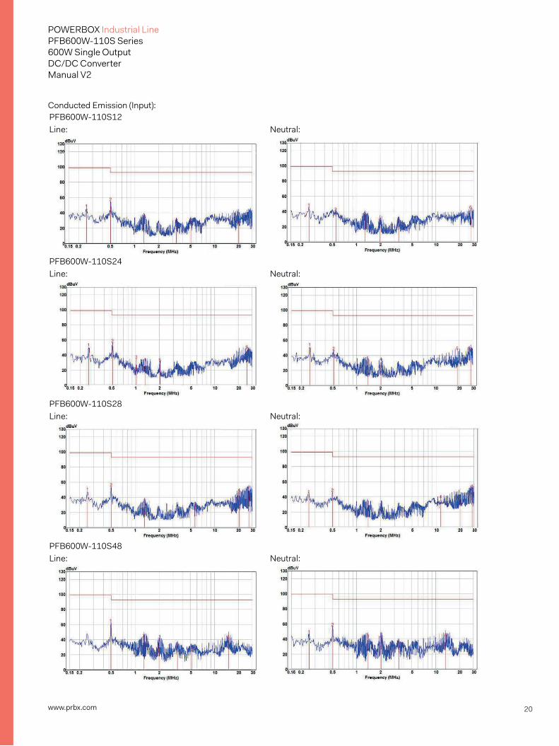
7.2 EMC ConsiderationSuggested circuits for conducted EMI meet EN50155 (EN50121-3-2)
EMI test board bottom side
EMI test board top side

19www.prbx.com
POWERBOX Industrial LinePFB600W-110S Series600W Single OutputDC/DC ConverterManual V2
Note:C1, C2: PCX2337 0.47uF/275V or equivalent. C3, C4: ALUMINUM CAP or equivalent.C5: VISHAY 293D TANTALUM CHIP CAP. D”<0.8R or equivalent.C6: CHIP CAP. 1812 or equivalent.CD1, CD2: SEMITEC CURRENT DIODE or equivalent.L1, L2: FERRITE CORE FERROXCUBE T29/19/15-3E6 f1.2mm*2/18T or equivalent.ZD1: LITTELFUSE TVS or equivalent.
(2) The external filter is required for output conducted noise meet EN50155: EN50121-3-2:2015
MODEL NO C1 C2 L1PFB600W-110S12 Y1 CAP Y1 CAP 1.0mH PFB600W-110S24 10000pF 10000pF PFB600W-110S28 PFB600W-110S48 Y1 CAP Y1 CAP 2.2mH 10000pF 10000pF Note L1:1.0mH FERRITE CORE FERROXCUBE T29/19/15-3E6f1.0mm*3/9T or equivalent. 2.2mH FERRITE CORE FERROXCUBE T29/19/15-3E6f1.2mm*1/14T or equivalent.
20www.prbx.com
POWERBOX Industrial LinePFB600W-110S Series600W Single OutputDC/DC ConverterManual V2
Conducted Emission (Input): PFB600W-110S12 Line: Neutral:
PFB600W-110S24 Line: Neutral:
PFB600W-110S28 Line: Neutral:
PFB600W-110S48 Line: Neutral:

21www.prbx.com
POWERBOX Industrial LinePFB600W-110S Series600W Single OutputDC/DC ConverterManual V2
Conducted Emission (Output): PFB600W-110S12 Positive: Negative:
PFB600W-110S24 Positive: Negative:
PFB600W-110S28 Positive: Negative:
PFB600W-110S48 Positive: Negative:

22www.prbx.com
POWERBOX Industrial LinePFB600W-110S Series600W Single OutputDC/DC ConverterManual V2
Radiated Emission: PFB600W-110S12 Vertical Horizontal
PFB600W-110S24 Vertical Horizontal
CFB600W-110S28 Vertical Horizontal
PFB600W-110S48 Vertical Horizontal

23www.prbx.com
POWERBOX Industrial LinePFB600W-110S Series600W Single OutputDC/DC ConverterManual V2
7.3 Suggested Configuration for RIA12 Surge Test

24www.prbx.com
POWERBOX Industrial LinePFB600W-110S Series600W Single OutputDC/DC ConverterManual V2
www.prbx.com 2018.06.08
8. Part NumberFormat: PFB600W – II S 00 L – Y
Parameter Series Nominal Input Voltage Number of Outputs Output Voltage Remote ON/OFF Logic Option Symbol PFB600W II X OO L Y 12: 12 Volts C0:Threaded Value PFB600W 110: 110 Volts S: Single 24: 24 Volts None: Negative Mounting 28: 28 Volts P: Negative Holes (M3*0.5) 48: 48 Volts
9. Mechanical Specifications
9.1 Mechanical Outline Diagrams
All Dimensions in Inches[mm] Pin
Millimeters:x.x=±0.5 , x.xx=±0.25 ±0.1Tolerance Inches:x.xx=±0.02 , x.xxx=±0.01 ±0.004
PIN CONNECTION0.40
0[10
.16]
0.90
0[22
.86]
1.40
0[35
.56]
0.199[5.05]
4.20[106.7]Mounting Inserts
2.40
[61.0]
0.50
[12.7]
0.22
[5.5]
4.60[116.8]
CONNECTIONPIN NUMBER
1234
5~78~10
111213
141516
-V Input+V Input
-On/O+On/O
+V Output-V Output
-Sense+Sense
TRIM
PCIOCAUX
0.10
0[2.54
]
0.40
0[10
.16]
0.30
0[7.62
]
0.15
0[3.81
]0.20
1[5.10
]
0.150[3.81]
0.150[3.81]
0.150[3.81]
0.150[3.81]
0.150[3.81]
0.301[7.64]
2.00
[50.8]
0.05
0[1.27
]-Vin
+Vin
ON/OFF
-
+