(powered by apache cloudstack) version citrix ... have the complete freedom to choose the right...
TRANSCRIPT

Citrix CloudPlatform(powered by ApacheCloudStack) Version4.5.1 Concepts Guide
Revised on July 03, 2015 09:30 am IST
Citrix CloudPlatform

Citrix CloudPlatform (powered by Apache CloudStack) Version 4.5.1 Concepts Guide
Citrix CloudPlatform (powered by Apache CloudStack) Version4.5.1 Concepts GuideRevised on July 03, 2015 09:30 am IST
Author Citrix CloudPlatform
© 2014 Citrix Systems, Inc. All rights reserved. Specifications are subject to change withoutnotice. Citrix Systems, Inc., the Citrix logo, Citrix XenServer, Citrix XenCenter, and CloudPlatformare trademarks or registered trademarks of Citrix Systems, Inc. All other brands or products aretrademarks or registered trademarks of their respective holders.
If you want to learn the concepts about CloudPlatform before you learn the ongoing operation andmaintenance of a CloudPlatform-powered cloud, read this document.

iii
1. About this Guide 11.1. About the Audience for this Guide ................................................................................. 11.2. Using the Product Documentation .................................................................................. 11.3. Experimental Features .................................................................................................. 11.4. Additional Information and Help ..................................................................................... 11.5. Contacting Support ....................................................................................................... 2
2. Concepts 32.1. About CloudPlatform ..................................................................................................... 32.2. CloudPlatform Features ................................................................................................. 3
3. Choosing a Deployment Architecture 53.1. Small-Scale Deployment ............................................................................................... 53.2. Large-Scale Redundant Setup ....................................................................................... 63.3. Separate Storage Network ............................................................................................ 73.4. Multi-Node Management Server .................................................................................... 73.5. Multi-Site Deployment ................................................................................................... 7
4. Cloud Infrastructure Concepts 94.1. Cloud Infrastructure Overview ........................................................................................ 94.2. Regions ...................................................................................................................... 104.3. Zones ......................................................................................................................... 104.4. Physical Networks ....................................................................................................... 12
4.4.1. Basic Zone Network Traffic Types ..................................................................... 124.4.2. Basic Zone Guest IP Addresses ....................................................................... 134.4.3. Advanced Zone Network Traffic Types .............................................................. 134.4.4. Advanced Zone Guest IP Addresses ................................................................. 144.4.5. Advanced Zone Public IP Addresses ................................................................. 144.4.6. System Reserved IP Addresses ........................................................................ 14
4.5. Pods ........................................................................................................................... 154.6. Clusters ...................................................................................................................... 164.7. Hosts .......................................................................................................................... 17
5. User Services Overview 195.1. Service Offerings, Disk Offerings, Network Offerings, and Templates ............................. 19
6. Service Offerings 216.1. Compute and Disk Service Offerings ........................................................................... 21
6.1.1. Custom Compute Offering ................................................................................ 216.2. System Service Offerings ............................................................................................ 22
7. Storage Concepts Used in CloudPlatform 237.1. Storage Overview ....................................................................................................... 237.2. About Primary Storage ................................................................................................ 23
7.2.1. Runtime Behavior of Primary Storage ................................................................ 237.2.2. Hypervisor Support for Primary Storage ............................................................ 247.2.3. Storage Tags ................................................................................................... 247.2.4. Maintenance Mode for Primary Storage ............................................................. 25
7.3. About Secondary Storage ............................................................................................ 257.4. About Storage Volumes .............................................................................................. 267.5. About Volume Snapshots ............................................................................................ 26
7.5.1. Automatic Snapshot Creation and Retention ...................................................... 277.5.2. Incremental Snapshots and Backup .................................................................. 277.5.3. Volume Status ................................................................................................. 277.5.4. Snapshot Restore ............................................................................................. 277.5.5. Snapshot Job Throttling .................................................................................... 277.5.6. VMware Volume Snapshot Performance ............................................................ 28

Citrix CloudPlatform (powered by Apache CloudStack) Version 4.5.1 Concepts Guide
iv
8. Networking for Users 298.1. Overview of Setting Up Networking for Users ............................................................... 298.2. About Virtual Networks ................................................................................................ 29
8.2.1. Isolated Networks ............................................................................................. 298.2.2. Shared Networks .............................................................................................. 298.2.3. Runtime Allocation of Virtual Network Resources ............................................... 30
8.3. About Redundant Virtual Routers ................................................................................. 308.4. Guest Traffic ............................................................................................................... 318.5. Networking in a Pod ................................................................................................... 318.6. Networking in a Zone .................................................................................................. 328.7. About Using a NetScaler Load Balancer ...................................................................... 338.8. About Elastic IP .......................................................................................................... 358.9. About Global Server Load Balancing ........................................................................... 37
8.9.1. Components of GSLB ...................................................................................... 378.9.2. How GSLB Works in CloudPlatform .................................................................. 37
8.10. Network Service Providers ......................................................................................... 398.11. Network Offerings ..................................................................................................... 39
9. About Virtual Machines in CloudPlatform 419.1. About Working with Virtual Machines ........................................................................... 419.2. VM Lifecycle ............................................................................................................... 429.3. Determining the Host for a VM .................................................................................... 429.4. Virtual Machine Snapshots .......................................................................................... 439.5. Working with ISOs ...................................................................................................... 43
10. About Templates in CloudPlatform 4510.1. The Default Template ................................................................................................ 4510.2. Private and Public Templates .................................................................................... 4510.3. The System VM Template ......................................................................................... 4610.4. Managing the Number of System VM Templates ........................................................ 4610.5. Multiple System VM Support for VMware ................................................................... 4710.6. Console Proxy .......................................................................................................... 4710.7. Virtual Router ............................................................................................................ 48
11. Securing Passwords in CloudPlatform 4911.1. About Password and Key Encryption ......................................................................... 4911.2. Changing the Default Password Encryption ................................................................ 49

Chapter 1.
1
About this Guide
1.1. About the Audience for this GuideThis guide is meant for anyone responsible for configuring and administering the public cloudinfrastructure and the private cloud infrastructure of enterprises using CloudPlatform such as cloudadministrators and Information Technology (IT) administrators.
1.2. Using the Product DocumentationThe following guides provide information about CloudPlatform:
• Citrix CloudPlatform (powered by Apache CloudStack) Installation Guide
• Citrix CloudPlatform (powered by Apache CloudStack) Concepts Guide
• Citrix CloudPlatform (powered by Apache CloudStack) Getting Started Guide
• Citrix CloudPlatform (powered by Apache CloudStack) Administration Guide
• Citrix CloudPlatform (powered by Apache CloudStack) Hypervisor Configuration Guide
• Citrix CloudPlatform (powered by Apache CloudStack) Developer's Guide
For complete information on any known limitations or issues in this release, see the CitrixCloudPlatform (powered by Apache CloudStack) Release Notes.
For information about the Application Programming Interfaces (APIs) that is used in this product, seethe API documents that are available with CloudPlatform.
1.3. Experimental FeaturesCloudPlatform product releases include some experimental features for customers to test andexperiment with in non-production environments, and share any feedback with Citrix. For any issueswith these experimental features, customers can open a support ticket but Citrix cannot commit todebugging or providing fixes for them.
The following experimental featues are inluded in this release:
• Linux Containers
• Supported Management Server OS and Supported Hypervisors: RHEL7/CentOS 7 for experimentaluse with Linux Containers
1.4. Additional Information and HelpTroubleshooting articles by the Citrix support team are available in the Citrix Knowledge Center atsupport.citrix.com/product/cs/.

Chapter 1. About this Guide
2
1.5. Contacting SupportThe support team is available to help customers plan and execute their installations. To contact thesupport team, log in to the support portal at support.citrix.com/cloudsupport1 by using the accountcredentials you received when you purchased your support contract.
1 http://support.citrix.com/cloudsupport

Chapter 2.
3
Concepts
2.1. About CloudPlatform CloudPlatform is a software platform that pools computing resources to build public, private, andhybrid Infrastructure as a Service (IaaS) clouds. CloudPlatform manages the network, storage, andcompute nodes that make up a cloud infrastructure. Use CloudPlatform to deploy, manage, andconfigure cloud computing environments.
Typical users are service providers and enterprises. With CloudPlatform, you can:
• Set up an on-demand, elastic cloud computing service. Service providers can sell self service virtualmachine instances, storage volumes, and networking configurations over the Internet.
• Set up an on-premise private cloud for use by employees. Rather than managing virtual machines inthe same way as physical machines, with CloudPlatform an enterprise can offer self-service virtualmachines to users without involving IT departments.
2.2. CloudPlatform FeaturesMultiple Hypervisor Support
CloudPlatform works with a variety of hypervisors. A single cloud deployment can contain multiplehypervisor implementations. You have the complete freedom to choose the right hypervisor for yourworkload.
CloudPlatform is designed to work with open source XenServer and KVM hypervisors as well asenterprise-grade hypervisors such as Citrix XenServer, Hyper-V, and VMware vSphere.
Massively Scalable Infrastructure Management
CloudPlatform can manage tens of thousands of servers installed in multiple geographically distributeddatacenters. The centralized management server scales linearly, eliminating the need for intermediate
Chapter 2. Concepts
4
cluster-level management servers. No single component failure can cause cloud-wide outage. Periodicmaintenance of the management server can be performed without affecting the functioning of virtualmachines running in the cloud.
Automatic Configuration Management
CloudPlatform automatically configures each guest virtual machine’s networking and storage settings.
CloudPlatform internally manages a pool of virtual appliances to support the cloud itself. Theseappliances offer services such as firewalling, routing, DHCP, VPN access, console proxy, storageaccess, and storage replication. The extensive use of virtual appliances simplifies the installation,configuration, and ongoing management of a cloud deployment.
Graphical User Interface
CloudPlatform offers an administrator's Web interface, used for provisioning and managing the cloud,as well as an end-user's Web interface, used for running VMs and managing VM templates. The UIcan be customized to reflect the desired service provider or enterprise look and feel.
API and Extensibility
CloudPlatform provides an API that gives programmatic access to all the management featuresavailable in the UI. This API enables the creation of command line tools and new user interfaces tosuit particular needs.
The CloudPlatform pluggable allocation architecture allows the creation of new types of allocators forthe selection of storage and hosts.
High Availability
CloudPlatform has a number of features to increase the availability of the system. The ManagementServer itself, which is the main controlling software at the heart of CloudPlatform, may be deployedin a multi-node installation where the servers are load balanced. MySQL may be configured to usereplication to provide for a manual failover in the event of database loss. For the hosts, CloudPlatformsupports NIC bonding and the use of separate networks for storage as well as iSCSI Multipath.
Chapter 3.
5
Choosing a Deployment ArchitectureThe architecture used in a deployment will vary depending on the size and purpose of the deployment.This section contains examples of deployment architecture, including a small-scale deployment usefulfor test and trial deployments and a fully-redundant large-scale setup for production deployments.
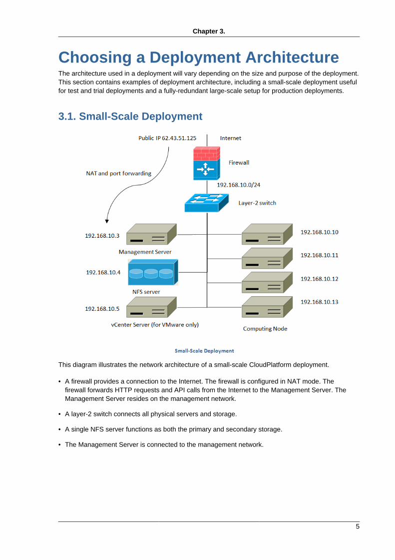
3.1. Small-Scale Deployment
This diagram illustrates the network architecture of a small-scale CloudPlatform deployment.
• A firewall provides a connection to the Internet. The firewall is configured in NAT mode. Thefirewall forwards HTTP requests and API calls from the Internet to the Management Server. TheManagement Server resides on the management network.
• A layer-2 switch connects all physical servers and storage.
• A single NFS server functions as both the primary and secondary storage.
• The Management Server is connected to the management network.

Chapter 3. Choosing a Deployment Architecture
6
3.2. Large-Scale Redundant Setup
This diagram illustrates the network architecture of a large-scale CloudPlatform deployment.
• A layer-3 switching layer is at the core of the data center. A router redundancy protocol like VRRPshould be deployed. Typically high-end core switches also include firewall modules. Separatefirewall appliances may also be used if the layer-3 switch does not have integrated firewallcapabilities. The firewalls are configured in NAT mode. The firewalls provide the following functions:
• Forwards HTTP requests and API calls from the Internet to the Management Server. TheManagement Server resides on the management network.
• When the cloud spans multiple zones, the firewalls should enable site-to-site VPN such thatservers in different zones can directly reach each other.
• A layer-2 access switch layer is established for each pod. Multiple switches can be stacked toincrease port count. In either case, redundant pairs of layer-2 switches should be deployed.
• The Management Server cluster (including front-end load balancers, Management Server nodes,and the MySQL database) is connected to the management network through a pair of loadbalancers.

Separate Storage Network
7
• Secondary storage servers are connected to the management network.
• Each pod contains storage and computing servers. Each storage and computing server should haveredundant NICs connected to separate layer-2 access switches.
3.3. Separate Storage NetworkIn the large-scale redundant setup described in the previous section, storage traffic can overload themanagement network. A separate storage network is optional for deployments. Storage protocols suchas iSCSI are sensitive to network delays. A separate storage network ensures guest network trafficcontention does not impact storage performance.
3.4. Multi-Node Management ServerThe CloudPlatform Management Server is deployed on one or more front-end servers connected toa single MySQL database. Optionally a pair of hardware load balancers distributes requests from theweb. A backup management server set may be deployed using MySQL replication at a remote site toadd DR capabilities.
The administrator must decide the following.
• Whether or not load balancers will be used.
• How many Management Servers will be deployed.
• Whether MySQL replication will be deployed to enable disaster recovery.
3.5. Multi-Site DeploymentThe CloudPlatform platform scales well into multiple sites through the use of zones.
There are two ways to configure the storage network:
• Bonded NIC and redundant switches can be deployed for NFS. In NFS deployments, redundantswitches and bonded NICs still result in one network (one CIDR block+ default gateway address).
• iSCSI can take advantage of two separate storage networks (two CIDR blocks each with its owndefault gateway). Multipath iSCSI client can failover and load balance between separate storagenetworks.

8

Chapter 4.
9
Cloud Infrastructure Concepts
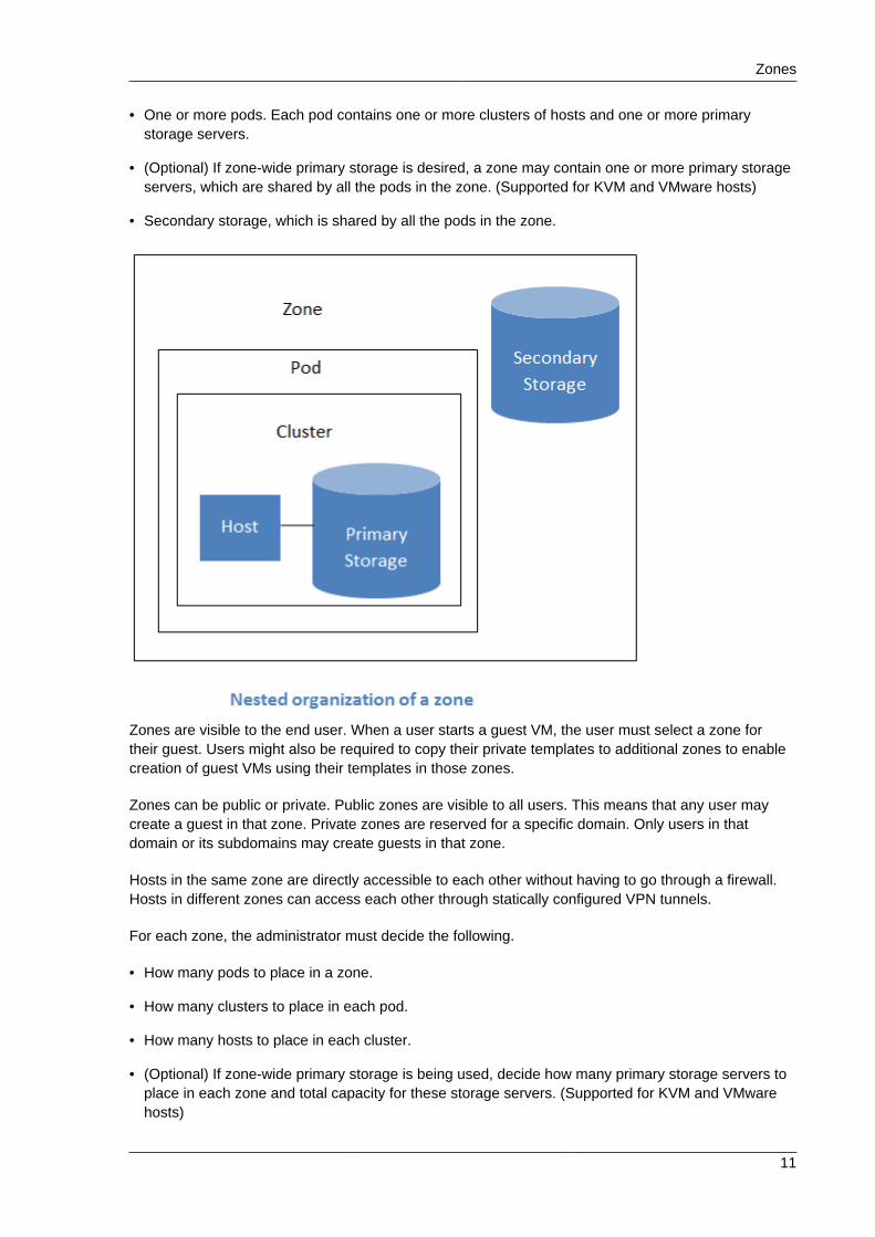
4.1. Cloud Infrastructure OverviewThe Management Server manages one or more zones (typically, datacenters) containing hostcomputers where guest virtual machines will run. The cloud infrastructure is organized as follows:
• Region: To increase reliability of the cloud, you can optionally group resources into multiplegeographic regions. A region consists of one or more zones.
• Zone: Typically, a zone is equivalent to a single datacenter. A zone consists of one or more podsand secondary storage.
• Pod: A pod is usually one rack of hardware that includes a layer-2 switch and one or more clusters.
• Cluster: A cluster consists of one or more hosts and primary storage.
• Host: A single compute node within a cluster. The hosts are where the actual cloud services run inthe form of guest virtual machines.
• Primary storage is associated with a cluster, and it can also be provisioned on a zone-wide basis. Itstores the disk volumes for all the VMs running on hosts in that cluster.
• Secondary storage is associated with a zone, and it can also be provisioned as object storage thatis available throughout the cloud. It stores templates, ISO images, and disk volume snapshots.
More Information

Chapter 4. Cloud Infrastructure Concepts
10
4.2. RegionsTo increase reliability of the cloud, you can optionally group resources into multiple geographicregions. A region is the largest available organizational unit within a CloudPlatform deployment. Aregion is made up of several availability zones, where each zone is equivalent to a datacenter. Eachregion is controlled by its own cluster of Management Servers, running in one of the zones. The zonesin a region are typically located in close geographical proximity. Regions are a useful technique forproviding fault tolerance and disaster recovery.
By grouping zones into regions, the cloud can achieve higher availability and scalability. Useraccounts can span regions, so that users can deploy VMs in multiple, widely-dispersed regions.Even if one of the regions becomes unavailable, the services are still available to the end-userthrough VMs deployed in another region. And by grouping communities of zones under their ownnearby Management Servers, the latency of communications within the cloud is reduced compared tomanaging widely-dispersed zones from a single central Management Server.
Usage records can also be consolidated and tracked at the region level, creating reports or invoicesfor each geographic region.
Regions are visible to the end user. When a user starts a guest VM on a particular CloudPlatformManagement Server, the user is implicitly selecting that region for their guest. Users might also berequired to copy their private templates to additional regions to enable creation of guest VMs usingtheir templates in those regions.
4.3. ZonesA zone is the second largest organizational unit within a CloudPlatform deployment. A zone typicallycorresponds to a single datacenter, although it is permissible to have multiple zones in a datacenter.The benefit of organizing infrastructure into zones is to provide physical isolation and redundancy. Forexample, each zone can have its own power supply and network uplink, and the zones can be widelyseparated geographically (though this is not required).
A zone consists of:
Zones
11
• One or more pods. Each pod contains one or more clusters of hosts and one or more primarystorage servers.
• (Optional) If zone-wide primary storage is desired, a zone may contain one or more primary storageservers, which are shared by all the pods in the zone. (Supported for KVM and VMware hosts)
• Secondary storage, which is shared by all the pods in the zone.
Zones are visible to the end user. When a user starts a guest VM, the user must select a zone fortheir guest. Users might also be required to copy their private templates to additional zones to enablecreation of guest VMs using their templates in those zones.
Zones can be public or private. Public zones are visible to all users. This means that any user maycreate a guest in that zone. Private zones are reserved for a specific domain. Only users in thatdomain or its subdomains may create guests in that zone.
Hosts in the same zone are directly accessible to each other without having to go through a firewall.Hosts in different zones can access each other through statically configured VPN tunnels.
For each zone, the administrator must decide the following.
• How many pods to place in a zone.
• How many clusters to place in each pod.
• How many hosts to place in each cluster.
• (Optional) If zone-wide primary storage is being used, decide how many primary storage servers toplace in each zone and total capacity for these storage servers. (Supported for KVM and VMwarehosts)
Chapter 4. Cloud Infrastructure Concepts
12
• How many primary storage servers to place in each cluster and total capacity for these storageservers.
• How much secondary storage to deploy in a zone.
When you add a new zone, you will be prompted to configure the zone’s physical network and add thefirst pod, cluster, host, primary storage, and secondary storage.
(VMware) In order to support zone-wide functions for VMware, CloudPlatform is aware of VMwareDatacenters and can map each Datacenter to a CloudPlatform zone. To enable features like storagelive migration and zone-wide primary storage for VMware hosts, CloudPlatform has to make surethat a zone contains only a single VMware Datacenter. Therefore, when you are creating a newCloudPlatform zone, you can select a VMware Datacenter for the zone. If you are provisioning multipleVMware Datacenters, each one will be set up as a single zone in CloudPlatform.
Note
If you are upgrading from a previous CloudPlatform version, and your existing deploymentcontains a zone with clusters from multiple VMware Datacenters, that zone will not be forciblymigrated to the new model. It will continue to function as before. However, any new zone-wideoperations introduced in CloudPlatform 4.2, such as zone-wide primary storage and live storagemigration, will not be available in that zone.
4.4. Physical NetworksPart of adding a zone is setting up the physical network. One or (in an advanced zone) more physicalnetworks can be associated with each zone. The network corresponds to a NIC on the hypervisorhost. Each physical network can carry one or more types of network traffic. The choices of traffictype for each network vary depending on whether you are creating a zone with basic networking oradvanced networking.
A physical network is the actual network hardware and wiring in a zone. A zone can have multiplephysical networks. An administrator can:
• Add/Remove/Update physical networks in a zone
• Configure VLANs on the physical network
• Configure a name so the network can be recognized by hypervisors
• Configure the service providers (firewalls, load balancers, etc.) available on a physical network
• Configure the IP addresses trunked to a physical network
• Specify what type of traffic is carried on the physical network, as well as other properties likenetwork speed
4.4.1. Basic Zone Network Traffic TypesWhen basic networking is used, there can be only one physical network in the zone. That physicalnetwork carries the following traffic types:

Basic Zone Guest IP Addresses
13
• Guest. When end users run VMs, they generate guest traffic. The guest VMs communicate witheach other over a network that can be referred to as the guest network. Each pod in a basic zoneis a broadcast domain, and therefore each pod has a different IP range for the guest network. Theadministrator must configure the IP range for each pod.
• Management. When CloudPlatform’s internal resources communicate with each other, theygenerate management traffic. This includes communication between hosts, system VMs (VMsused by CloudPlatform to perform various tasks in the cloud), and any other component thatcommunicates directly with the CloudPlatform Management Server. You must configure the IPrange for the system VMs to use.
Note
We strongly recommend the use of separate NICs for management traffic and guest traffic.
• Public. Public traffic is generated when VMs in the cloud access the Internet. Publicly accessibleIPs must be allocated for this purpose. End users can use the CloudPlatform UI to acquire theseIPs to implement NAT between their guest network and the public network, as described in the9.14 Acquiring a New IP Address section of the CloudPlatform (powered by Apache CloudStack)Version 4.5.1 Administration Guide. Public traffic is generated only in EIP-enabled basic zones.For more information, refer to the 9.20 About Elastic IP section of the CloudPlatform (powered byApache CloudStack) Version 4.5.1 Administration Guide.
• Storage. Traffic such as VM templates and snapshots, which is sent between the secondary storageVM and secondary storage servers. CloudPlatform uses a separate Network Interface Controller(NIC) named storage NIC for storage network traffic. Use of a storage NIC that always operates ona high bandwidth network allows fast template and snapshot copying. You must configure the IPrange to use for the storage network.
In a basic network, configuring the physical network is fairly straightforward. In most cases, you onlyneed to configure one guest network to carry traffic that is generated by guest VMs. If you use aNetScaler load balancer and enable its elastic IP and elastic load balancing (EIP and ELB) features,you must also configure a network to carry public traffic. CloudPlatform takes care of presenting thenecessary network configuration steps to you in the UI when you add a new zone.
4.4.2. Basic Zone Guest IP AddressesWhen basic networking is used, CloudPlatform will assign IP addresses in the CIDR of the pod to theguests in that pod. The administrator must add a direct IP range on the pod for this purpose. TheseIPs are in the same VLAN as the hosts.
4.4.3. Advanced Zone Network Traffic TypesWhen advanced networking is used, there can be multiple physical networks in the zone. Eachphysical network can carry one or more traffic types, and you need to let CloudPlatform know whichtype of network traffic you want each network to carry. The traffic types in an advanced zone are:
• Guest. When end users run VMs, they generate guest traffic. The guest VMs communicate witheach other over a network that can be referred to as the guest network. This network can beisolated or shared. In an isolated guest network, the administrator needs to reserve VLAN ranges to

Chapter 4. Cloud Infrastructure Concepts
14
provide isolation for each CloudPlatform account’s network (potentially a large number of VLANs). Ina shared guest network, all guest VMs share a single network.
• Management. When CloudPlatform’s internal resources communicate with each other, theygenerate management traffic. This includes communication between hosts, system VMs (VMsused by CloudPlatform to perform various tasks in the cloud), and any other component thatcommunicates directly with the CloudPlatform Management Server. You must configure the IPrange for the system VMs to use.
• Public. Public traffic is generated when VMs in the cloud access the Internet. Publicly accessibleIPs must be allocated for this purpose. End users can use the CloudPlatform UI to acquire theseIPs to implement NAT between their guest network and the public network, as described in the9.14 Acquiring a New IP Address section of the CloudPlatform (powered by Apache CloudStack)Version 4.5.1 Administration Guide.
• Storage. Traffic such as VM templates and snapshots, which is sent between the secondary storageVM and secondary storage servers. CloudPlatform uses a separate Network Interface Controller(NIC) named storage NIC for storage network traffic. Use of a storage NIC that always operates ona high bandwidth network allows fast template and snapshot copying. You must configure the IPrange to use for the storage network.
These traffic types can each be on a separate physical network, or they can be combined with certainrestrictions. When you use the Add Zone wizard in the UI to create a new zone, you are guided intomaking only valid choices.
4.4.4. Advanced Zone Guest IP AddressesGuest IP addresses are private IP addresses that are used for internal communication. Whenadvanced networking is used, the administrator can create additional networks for use by the guests.These networks can either be made available to all accounts in the zone, or they can be scoped toa single account. If they are scoped to a single account, only the named account may create gueststhat attach to these networks. The networks are defined by a VLAN ID, IP range, and gateway. Theadministrator may provision thousands of these networks if desired. Additionally, the administrator canreserve a part of the IP address space for non-CloudPlatform VMs and servers (For more information,refer to the 9.17 IP Reservation in Isolated Guest Networks section of the CloudPlatform (poweredby Apache CloudStack) Version 4.5.1 Administration Guide.).
4.4.5. Advanced Zone Public IP AddressesPublic IP addresses are used for communicating with the Internet. When advanced networking isused, the administrator can create additional networks for use by the guests. The networks aredefined by a VLAN ID, IP range, and gateway. The administrator may provision thousands of thesenetworks if desired. Network Address Translation (NAT) protocol is used for converting the private IPaddress to a public IP address.
4.4.6. System Reserved IP AddressesIn each zone, you need to configure a range of reserved IP addresses for the management network.This network carries communication between the CloudPlatform Management Server and varioussystem VMs, such as Secondary Storage VMs, Console Proxy VMs, and Virtual Router VM.
The reserved IP addresses must be unique across the cloud. You cannot, for example, have a host inone zone which has the same private IP address as a host in another zone.
Pods
15
The hosts in a pod are assigned private IP addresses. These are typically RFC1918 addresses. TheConsole Proxy and Secondary Storage system VMs are also allocated private IP addresses in theCIDR of the pod that they are created in.
Make sure computing servers and Management Servers use IP addresses outside of the SystemReserved IP range. For example, suppose the System Reserved IP range starts at 192.168.154.2 andends at 192.168.154.7. CloudPlatform can use .2 to .7 for System VMs. This leaves the rest of the podCIDR, from .8 to .254, for the Management Server and hypervisor hosts.
In all zones:
Provide private IPs for the system in each pod and provision them in CloudPlatform.
For KVM and XenServer, the recommended number of private IPs per pod is one per host. If youexpect a pod to grow, add enough private IPs now to accommodate the growth.
In a zone that uses advanced networking:
When advanced networking is being used, the number of private IP addresses available in each podvaries depending on which hypervisor is running on the nodes in that pod. Citrix XenServer and KVMuse link-local addresses, which in theory provide more than 65,000 private IP addresses within theaddress block. As the pod grows over time, this should be more than enough for any reasonablenumber of hosts as well as IP addresses for guest virtual routers. VMWare ESXi, by contrast usesany administrator-specified subnetting scheme, and the typical administrator provides only 255 IPsper pod. Since these are shared by physical machines, the guest virtual router, and other entities, it ispossible to run out of private IPs when scaling up a pod whose nodes are running ESXi.
To ensure adequate headroom to scale private IP space in an ESXi pod that uses advancednetworking, use one or more of the following techniques:
• Specify a larger CIDR block for the subnet. A subnet mask with a /20 suffix will provide more than4,000 IP addresses.
• Create multiple pods, each with its own subnet. For example, if you create 10 pods and each podhas 255 IPs, this will provide 2,550 IP addresses.
For vSphere with advanced networking, we recommend provisioning enough private IPs for yourtotal number of customers, plus enough for the required CloudPlatform System VMs. Typically, about10 additional IPs are required for the System VMs. For more information about System VMs, referto Chapter 11 Working with System Virtual Machines in the CloudPlatform (powered by ApacheCloudStack) Version 4.5.1 Administration Guide.
4.5. PodsA pod often represents a single rack. Hosts in the same pod are in the same subnet. A pod is thethird-largest organizational unit within a CloudPlatform deployment. Pods are contained within zones,and zones can be contained within regions. Each zone can contain one or more pods. A pod consistsof one or more clusters of hosts and one or more primary storage servers. Pods are not visible to theend user.

Chapter 4. Cloud Infrastructure Concepts
16
4.6. ClustersA cluster provides a way to group hosts. To be precise, a cluster is a XenServer server pool, a set ofKVM servers or a VMware cluster preconfigured in vCenter. The hosts in a cluster all have identicalhardware, run the same hypervisor, are on the same subnet, and access the same shared primarystorage. Virtual machine instances (VMs) can be live-migrated from one host to another within thesame cluster without interrupting service to the user.
A cluster is the fourth-largest organizational unit within a CloudPlatform deployment. Clustersare contained within pods, pods are contained within zones, and zones can be contained withinregions. Size of the cluster is only limited by the underlying hypervisor, although the CloudPlatformrecommends you stay below the theoretically allowed maximum cluster size in most cases.
A cluster consists of one or more hosts and one or more primary storage servers.
Even when local storage is used, clusters are still required. In this case, there is just one host percluster.
(VMware) If you use VMware hypervisor hosts in your CloudPlatform deployment, each VMwarecluster is managed by a vCenter server. The CloudPlatform administrator must register the vCenter

Hosts
17
server with CloudPlatform. There may be multiple vCenter servers per zone. Each vCenter server maymanage multiple VMware clusters.
4.7. HostsA host is a single computer. Hosts provide the computing resources that run guest virtual machines.Each host has hypervisor software installed on it to manage the guest VMs. For example, a host canbe a Citrix XenServer server, a Linux KVM-enabled server, an ESXi server, or a Windows Hyper-Vserver.
The host is the smallest organizational unit within a CloudPlatform deployment. Hosts are containedwithin clusters, clusters are contained within pods, pods are contained within zones, and zones can becontained within regions.
Hosts in a CloudPlatform deployment:
• Provide the CPU, memory, storage, and networking resources needed to host the virtual machines
• Interconnect using a high bandwidth TCP/IP network and connect to the Internet
• May reside in multiple data centers across different geographic locations
• May have different capacities (different CPU speeds, different amounts of RAM, etc.), although thehosts within a cluster must all be homogeneous
Additional hosts can be added at any time to provide more capacity for guest VMs.
CloudPlatform automatically detects the amount of CPU and memory resources provided by the hosts.
Hosts are not visible to the end user. An end user cannot determine which host their guest has beenassigned to.
For a host to function in CloudPlatform, you must do the following:
• Install hypervisor software on the host
• Assign an IP address to the host
• Ensure the host is connected to the CloudPlatform Management Server.

18

Chapter 5.
19
User Services OverviewIn addition to the physical and logical infrastructure of your cloud, and the CloudPlatform software andservers, you also need a layer of user services so that people can actually make use of the cloud.This means not just a user UI, but a set of options and resources that users can choose from, suchas templates for creating virtual machines, disk storage, and more. If you are running a commercialservice, you will be keeping track of what services and resources users are consuming and chargingthem for that usage. Even if you do not charge anything for people to use your cloud – say, if the usersare strictly internal to your organization, or just friends who are sharing your cloud – you can still keeptrack of what services they use and how much of them.
5.1. Service Offerings, Disk Offerings, Network Offerings,and TemplatesA user creating a new instance can make a variety of choices about its characteristics and capabilities.CloudPlatform provides several ways to present users with choices when creating a new instance:
• Service Offerings, defined by the CloudPlatform administrator, provide a choice of CPU speed,number of CPUs, RAM size, tags on the root disk, and other choices. See Creating a New ComputeOffering.
• Disk Offerings, defined by the CloudPlatform administrator, provide a choice of disk size for primarydata storage. See Creating a New Disk Offering.
• Network Offerings, defined by the CloudPlatform administrator, describe the feature set that isavailable to end users from the virtual router or external networking devices on a given guestnetwork. See Network Offerings.
• Templates, defined by the CloudPlatform administrator or by any CloudPlatform user, are thebase OS images that the user can choose from when creating a new instance. For example,CloudPlatform includes CentOS as a template. See Working with Templates.
In addition to these choices that are provided for users, there is another type of service offeringwhich is available only to the CloudPlatform root administrator, and is used for configuring virtualinfrastructure resources. For more information, see Upgrading a Virtual Router with System ServiceOfferings.

20

Chapter 6.
21
Service OfferingsIn this chapter we discuss compute, disk, and system service offerings. Network offerings arediscussed in the section on setting up networking for users.
6.1. Compute and Disk Service OfferingsA service offering is a set of virtual hardware features such as CPU core count and speed, memory,and disk size. The CloudPlatform administrator can set up various offerings, and then end userschoose from the available offerings when they create a new VM. Based on the user’s selectedoffering, CloudPlatform emits usage records that can be integrated with billing systems.
Some characteristics of service offerings must be defined by the CloudPlatform administrator, andothers can be left undefined so that the end-user can enter their own desired values. This is useful toreduce the number of offerings the CloudPlatform administrator has to define. Instead of defining acompute offering for every imaginable combination of values that a user might want, the administratorcan define offerings that provide some flexibility to the users and can serve as the basis for severaldifferent VM configurations.
A service offering includes the following elements:
• CPU, memory, and network resource guarantees
• How resources are metered
• How the resource usage is charged
• How often the charges are generated
For example, one service offering might allow users to create a virtual machine instance that isequivalent to a 1 GHz Intel® Core™ 2 CPU, with 1 GB memory at $0.20/hour, with network trafficmetered at $0.10/GB.
CloudPlatform separates service offerings into compute offerings and disk offerings. The computeservice offering specifies:
• Guest CPU (optional). If not defined by the CloudPlatform administrator, users can pick the CPUattributes.
• Guest RAM (optional). If not defined by the CloudPlatform administrator, users can pick the RAM.
• Guest Networking type (virtual or direct)
• Tags on the root disk
The disk offering specifies:
• Disk size (optional). If not defined by the CloudPlatform administrator, users can pick the disk size.
• Tags on the data disk
6.1.1. Custom Compute OfferingCloudPlatform provides you the flexibility to specify the desired values for the number of CPU, CPUspeed, and memory while deploying a VM. As an admin, you create a Compute Offering by markingit as custom, and the users will be able to customize this dynamic Compute Offering by specifying the

Chapter 6. Service Offerings
22
memory, and CPU at the time of VM creation or upgrade. Use this offering to deploy VM by specifyingcustom values for the dynamic parameters.
Dynamic Compute Offerings can be used in following cases: deploying a VM, changing the computeoffering of a stopped VM and running VMs, which is nothing but scaling up. To support this feature anew field, Custom, has been added to the Create Compute Offering page in the UI. If the Custom fieldis checked, the user will be able to create a custom Compute Offering. During VM deployment you canspecify desired values for number of CPU, CPU speed, and memory.
To support this feature, usage events has been enhanced to register events for dynamically assignedresources. Usage events are registered when a VM is created from a custom compute offering, andupon changing the compute offering of a stopped or running VM. The values of the parameters, suchas CPU, speed, RAM are recorded.
6.2. System Service OfferingsSystem service offerings provide a choice of CPU speed, number of CPUs, tags, and RAM size, justas other service offerings do. But rather than being used for virtual machine instances and exposedto users, system service offerings are used to change the default properties of virtual routers, consoleproxies, and other system VMs. System service offerings are visible only to the CloudPlatform rootadministrator. CloudPlatform provides default system service offerings. The CloudPlatform rootadministrator can create additional custom system service offerings.
When CloudPlatform creates a virtual router for a guest network, it uses default settings which aredefined in the system service offering associated with the network offering. You can upgrade thecapabilities of the virtual router by applying a new network offering that contains a different systemservice offering. All virtual routers in that network will begin using the settings from the new serviceoffering.

Chapter 7.
23
Storage Concepts Used inCloudPlatform
7.1. Storage OverviewCloudPlatform defines two types of storage: primary and secondary. Primary storage can be accessedby either iSCSI or NFS. Additionally, direct attached storage may be used for primary storage.Secondary storage is always accessed using NFS or a combination of NFS and object storage.
There is no ephemeral storage in CloudPlatform. All volumes on all nodes are persistent.
7.2. About Primary StoragePrimary storage is associated with a cluster or (in KVM and VMware) a zone, and it stores the diskvolumes for all the VMs running on hosts.
You can add multiple primary storage servers to a cluster or zone. At least one is required. It istypically located close to the hosts for increased performance. CloudPlatform manages the allocationof guest virtual disks to particular primary storage devices.
It is useful to set up zone-wide primary storage when you want to avoid extra data copy operations.With cluster-based primary storage, data in the primary storage is directly available only to VMswithin that cluster. If a VM in a different cluster needs some of the data, it must be copied from onecluster to another, using the zone's secondary storage as an intermediate step. This operation can beunnecessarily time-consuming.
For Hyper-V, SMB/CIFS storage is supported. Note that Zone-wide Primary Storage is not supportedin Hyper-V.
CloudPlatform is designed to work with all standards-compliant iSCSI and NFS servers that aresupported by the underlying hypervisor, including, for example:
• Dell EqualLogic™ for iSCSI
• Network Appliances filers for NFS and iSCSI
• Scale Computing for NFS
If you intend to use only local disk for your installation, you can skip adding separate primary storage.
7.2.1. Runtime Behavior of Primary StorageRoot volumes are created automatically when a virtual machine is created. Root volumes are deletedwhen the VM is destroyed. Data volumes can be created and dynamically attached to VMs (although,when the Oracle VM hypervisor is used, the VM must be stopped before an additional volume can beattached). Data volumes are not deleted when VMs are destroyed.
Administrators should monitor the capacity of primary storage devices and add additional primarystorage as needed. See the Advanced Installation Guide.
Administrators add primary storage to the system by creating a CloudPlatform storage pool. Eachstorage pool is associated with a cluster.
Chapter 7. Storage Concepts Used in CloudPlatform
24
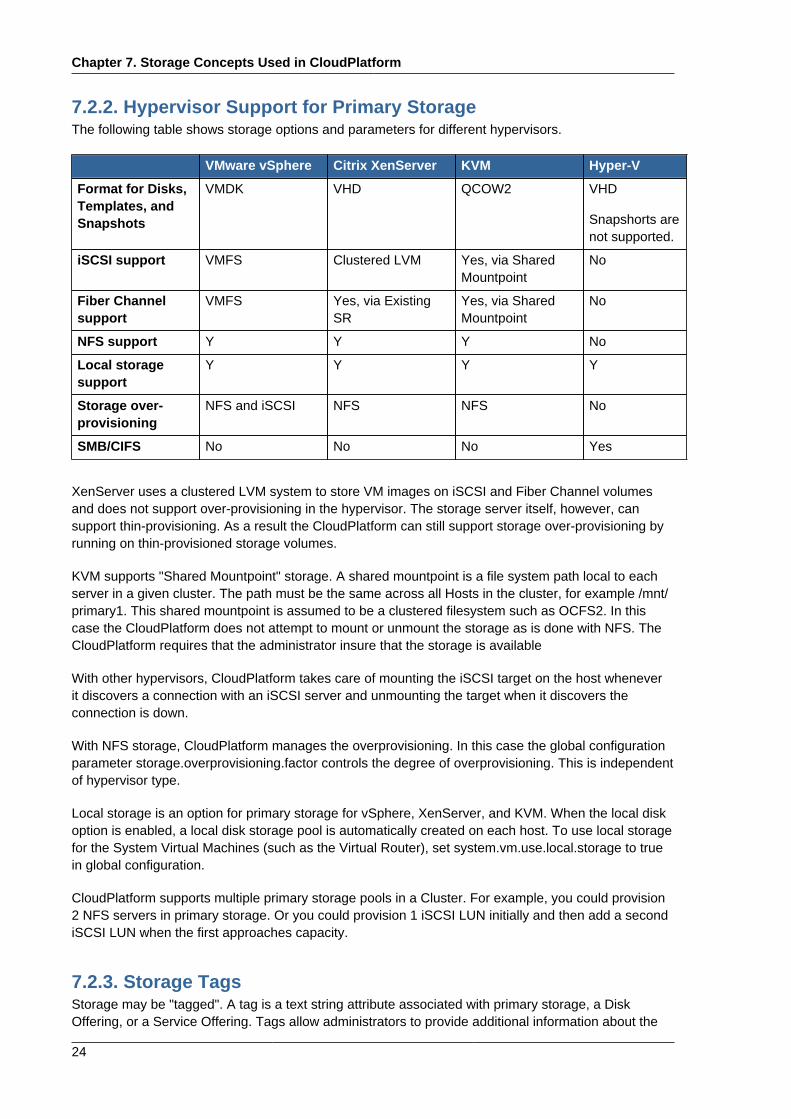
7.2.2. Hypervisor Support for Primary StorageThe following table shows storage options and parameters for different hypervisors.
VMware vSphere Citrix XenServer KVM Hyper-V
Format for Disks,Templates, andSnapshots
VMDK VHD QCOW2 VHD
Snapshorts arenot supported.
iSCSI support VMFS Clustered LVM Yes, via SharedMountpoint
No
Fiber Channelsupport
VMFS Yes, via ExistingSR
Yes, via SharedMountpoint
No
NFS support Y Y Y No
Local storagesupport
Y Y Y Y
Storage over-provisioning
NFS and iSCSI NFS NFS No
SMB/CIFS No No No Yes
XenServer uses a clustered LVM system to store VM images on iSCSI and Fiber Channel volumesand does not support over-provisioning in the hypervisor. The storage server itself, however, cansupport thin-provisioning. As a result the CloudPlatform can still support storage over-provisioning byrunning on thin-provisioned storage volumes.
KVM supports "Shared Mountpoint" storage. A shared mountpoint is a file system path local to eachserver in a given cluster. The path must be the same across all Hosts in the cluster, for example /mnt/primary1. This shared mountpoint is assumed to be a clustered filesystem such as OCFS2. In thiscase the CloudPlatform does not attempt to mount or unmount the storage as is done with NFS. TheCloudPlatform requires that the administrator insure that the storage is available
With other hypervisors, CloudPlatform takes care of mounting the iSCSI target on the host wheneverit discovers a connection with an iSCSI server and unmounting the target when it discovers theconnection is down.
With NFS storage, CloudPlatform manages the overprovisioning. In this case the global configurationparameter storage.overprovisioning.factor controls the degree of overprovisioning. This is independentof hypervisor type.
Local storage is an option for primary storage for vSphere, XenServer, and KVM. When the local diskoption is enabled, a local disk storage pool is automatically created on each host. To use local storagefor the System Virtual Machines (such as the Virtual Router), set system.vm.use.local.storage to truein global configuration.
CloudPlatform supports multiple primary storage pools in a Cluster. For example, you could provision2 NFS servers in primary storage. Or you could provision 1 iSCSI LUN initially and then add a secondiSCSI LUN when the first approaches capacity.
7.2.3. Storage TagsStorage may be "tagged". A tag is a text string attribute associated with primary storage, a DiskOffering, or a Service Offering. Tags allow administrators to provide additional information about the

Maintenance Mode for Primary Storage
25
storage. For example, that is a "SSD" or it is "slow". Tags are not interpreted by CloudPlatform. Theyare matched against tags placed on service and disk offerings. CloudPlatform requires all tags onservice and disk offerings to exist on the primary storage before it allocates root or data disks on theprimary storage. Service and disk offering tags are used to identify the requirements of the storagethat those offerings have. For example, the high end service offering may require "fast" for its root diskvolume.
The interaction between tags, allocation, and volume copying across clusters and pods can becomplex. To simplify the situation, use the same set of tags on the primary storage for all clusters ina pod. Even if different devices are used to present those tags, the set of exposed tags can be thesame.
7.2.4. Maintenance Mode for Primary StoragePrimary storage may be placed into maintenance mode. This is useful, for example, to replace faultyRAM in a storage device. Maintenance mode for a storage device will first stop any new guests frombeing provisioned on the storage device. Then it will stop all guests that have any volume on thatstorage device. When all such guests are stopped the storage device is in maintenance mode andmay be shut down. When the storage device is online again you may cancel maintenance mode forthe device. The CloudPlatform will bring the device back online and attempt to start all guests thatwere running at the time of the entry into maintenance mode.
7.3. About Secondary StorageSecondary storage stores the following:
• Templates — OS images that can be used to boot VMs and can include additional configurationinformation, such as installed applications
• ISO images — disc images containing data or bootable media for operating systems
• Disk volume snapshots — saved copies of VM data which can be used for data recovery or tocreate new templates
The items in secondary storage are available to all hosts in the scope of the secondary storage, whichmay be defined as per zone or per region.
To make items in secondary storage available to all hosts throughout the cloud, you can add objectstorage in addition to the zone-based NFS Secondary Staging Store. It is not necessary to copytemplates and snapshots from one zone to another, as would be required when using zone NFSalone. Everything is available everywhere.
For Hyper-V hosts, SMB storage is supported.
Note
Object storage is not supported on Hyper-V.

Chapter 7. Storage Concepts Used in CloudPlatform
26
Warning
Heterogeneous Secondary Storage is not supported in Regions. For example, you cannot set upmultiple zones, one using NFS secondary and the other using S3 secondary.
7.4. About Storage VolumesA volume provides storage to a guest VM. The volume can provide for a root disk or an additional datadisk. CloudPlatform supports additional volumes for guest VMs.
Volumes are created for a specific hypervisor type. A volume that has been attached to guest usingone hypervisor type (e.g, XenServer) may not be attached to a guest that is using another hypervisortype (e.g. vSphere, Oracle VM, KVM). This is because the different hypervisors use different diskimage formats.
CloudPlatform defines a volume as a unit of storage available to a guest VM. Volumes are either rootdisks or data disks. The root disk has “/” in the file system and is usually the boot device. Data disksprovide for additional storage (e.g. As “/opt” or “D:”). Every guest VM has a root disk, and VMs canalso optionally have a data disk. End users can mount multiple data disks to guest VMs. Users choosedata disks from the disk offerings created by administrators. The user can create a template from avolume as well; this is the standard procedure for private template creation. Volumes are hypervisor-specific: a volume from one hypervisor type may not be used on a guest of another hypervisor type.
Note
CloudPlatform supports attaching up to 13 data disks to a VM on XenServer hypervisor versions6.0 and above. For the VMs on other hypervisor types, the data disk limit is 6.
7.5. About Volume SnapshotsCloudPlatform supports snapshots of disk volumes. Snapshots are a point-in-time capture of virtualmachine disks. Memory and CPU states are not captured.
Snapshots may be taken for volumes, including both root and data disks. The administrator places alimit on the number of stored snapshots per user. Users can create new volumes from the snapshotfor recovery of particular files and they can create templates from snapshots to boot from a restoreddisk.
Users can create snapshots manually or by setting up automatic recurring snapshot policies. Userscan also create disk volumes from snapshots, which may be attached to a VM like any other diskvolume. Snapshots of both root disks and data disks are supported. However, CloudPlatform does notcurrently support booting a VM from a recovered root disk. A disk recovered from snapshot of a rootdisk is treated as a regular data disk; the data on recovered disk can be accessed by attaching thedisk to a VM.
A completed snapshot is copied from primary storage to secondary storage, where it is stored untildeleted or purged by newer snapshot.

Automatic Snapshot Creation and Retention
27
This feature is supported for the following hypervisors: XenServer VMware, and KVM.
7.5.1. Automatic Snapshot Creation and Retention(Supported for the following hypervisors: XenServer, VMware vSphere, and KVM)
Users can set up a recurring snapshot policy to automatically create multiple snapshots of a diskat regular intervals. Snapshots can be created on an hourly, daily, weekly, or monthly interval. Onesnapshot policy can be set up per disk volume. For example, a user can set up a daily snapshot at02:30.
With each snapshot schedule, users can also specify the number of scheduled snapshots to beretained. Older snapshots that exceed the retention limit are automatically deleted. This user-definedlimit must be equal to or lower than the global limit set by the CloudPlatform administrator. The limitapplies only to those snapshots that are taken as part of an automatic recurring snapshot policy.Additional manual snapshots can be created and retained.
7.5.2. Incremental Snapshots and BackupSnapshots are created on primary storage where a disk resides. After a snapshot is created, it isimmediately backed up to secondary storage and removed from primary storage for optimal utilizationof space on primary storage.
CloudPlatform does incremental backups for some hypervisors. When incremental backups aresupported, every backup is a full backup.
VMware vSphere Citrix XenServer KVM Hyper-V
Support forIncrementalBackup
N Y N N
7.5.3. Volume StatusWhen a snapshot operation is triggered by means of a recurring snapshot policy, a snapshot isskipped if a volume has remained inactive since its last snapshot was taken. A volume is consideredto be inactive if it is either detached or attached to a VM that is not running. CloudPlatform ensuresthat at least one snapshot is taken since the volume last became inactive.
When a snapshot is taken manually, a snapshot is always created regardless of whether a volume hasbeen active or not.
7.5.4. Snapshot RestoreThere are two paths to restoring snapshots. Users can create a volume from the snapshot. Thevolume can then be mounted to a VM and files recovered as needed. Alternatively, a template maybe created from the snapshot of a root disk. The user can then boot a VM from this template to effectrecovery of the root disk.
7.5.5. Snapshot Job ThrottlingWhen a snapshot of a virtual machine is requested, the snapshot job runs on the same host wherethe VM is running or, in the case of a stopped VM, the host where it ran last. If many snapshotsare requested for VMs on a single host, this can lead to problems with too many snapshot jobsoverwhelming the resources of the host.
Chapter 7. Storage Concepts Used in CloudPlatform
28
To address this situation, the cloud's root administrator can throttle how many snapshot jobs areexecuted simultaneously on the hosts in the cloud by using the new global configuration settingconcurrent.snapshots.threshold.perhost. By using this setting, the administrator can better ensurethat snapshot jobs do not time out and hypervisor hosts do not experience performance issues due tohosts being overloaded with too many snapshot requests.
Set concurrent.snapshots.threshold.perhost to a value that represents a best guess about howmany snapshot jobs the hypervisor hosts can execute at one time, given the current resources of thehosts and the number of VMs running on the hosts. If a given host has more snapshot requests, theadditional requests are placed in a waiting queue. No new snapshot jobs will start until the number ofcurrently executing snapshot jobs falls below the configured limit.
The admin can also set job.expire.minutes to place a maximum on how long a snapshot request willwait in the queue. If this limit is reached, the snapshot request fails and returns an error message.
7.5.6. VMware Volume Snapshot PerformanceWhen you take a snapshot of a data or root volume on VMware, CloudPlatform uses an efficientstorage technique to improve performance.
A snapshot is not immediately exported from vCenter to a mounted NFS share and packaged intoan OVA file format. This operation would consume time and resources. Instead, the original fileformats (e.g., VMDK) provided by vCenter are retained. An OVA file will only be created as needed, ondemand. To generate the OVA, CloudPlatform uses information in a properties file (*.ova.meta) whichit stored along with the original snapshot data.
Note
For upgrading customers: This process applies only to newly created snapshots after upgradeto CloudPlatform 4.2. Snapshots that have already been taken and stored in OVA format willcontinue to exist in that format, and will continue to work as expected.

Chapter 8.
29
Networking for Users
8.1. Overview of Setting Up Networking for UsersPeople using cloud infrastructure have a variety of needs and preferences when it comes to thenetworking services provided by the cloud. As a CloudPlatform administrator, you can do the followingthings to set up networking for your users:
• Set up physical networks in zones
• Set up several different providers for the same service on a single physical network (for example,both Cisco and Juniper firewalls)
• Bundle different types of network services into network offerings, so users can choose the desirednetwork services for any given virtual machine
• Add new network offerings as time goes on so end users can upgrade to a better class of service ontheir network
• Provide more ways for a network to be accessed by a user, such as through a project of which theuser is a member
8.2. About Virtual NetworksA virtual network is a logical construct that enables multi-tenancy on a single physical network. InCloudPlatform a virtual network can be shared or isolated.
8.2.1. Isolated NetworksAn isolated network can be accessed only by virtual machines of a single account. Isolated networkshave the following properties.
• Resources such as VLAN are allocated and garbage collected dynamically
• There is one network offering for the entire network
• The network offering can be upgraded or downgraded but it is for the entire network
8.2.2. Shared NetworksA shared network can be accessed by virtual machines that belong to many different accounts.Network Isolation on shared networks is accomplished by using techniques such as security groups,which is supported only in Basic zones.
• Shared Networks are created by the administrator
• Shared Networks can be designated to a certain domain
• Shared Network resources such as VLAN and physical network that it maps to are designated bythe administrator
• Shared Networks can be isolated by security groups
• Public Network is a shared network that is not shown to the end users

Chapter 8. Networking for Users
30
• Source NAT per zone is not supported when the service provider is virtual router. However, SourceNAT per account is supported with virtual router in a Shared Network.
8.2.3. Runtime Allocation of Virtual Network ResourcesWhen you define a new virtual network, all your settings for that network are stored in CloudPlatform.The actual network resources are activated only when the first virtual machine starts in the network.When all virtual machines have left the virtual network, the network resources are garbage collectedso they can be allocated again. This helps to conserve network resources.
8.3. About Redundant Virtual RoutersEach CloudPlatform account uses a virtual router to provide network services to the resources thatare part of that account. Typically in CloudPlatform, all the user VMs are in a private network and theycommunicate with the external network using a virtual router. They use virtual router as a gateway.If the virtual router fails, the network connection to the guest VMs gets disabled and the users faceproblems in accessing the guest VMs.
To address such exigencies, CloudPlatform provides the Redundant Virtual Router (RVR) feature.This feature enables the guest network to recover and resume operations if the virtual router thatconnects it to the external network fails. After you enable this feature, each guest network will havetwo virtual routers. The virtual router that receives and responds to the guest VM network is known asMaster. The other virtual router is known as Backup. The Backup virtual router remains in the passivemode.
If the Master virtual router is down, the Backup virtual router takes the Master's role. The Backuprouter takes only a few seconds to get activated. This ensures minimum downtime. Another virtualrouter will be launched as a new Backup router. CloudPlatform uses the Virtual Redundant RouterProtocol (VRRP) for the communication between the Master and the Backup virtual routers.
CloudPlatform uses the keepalived process and the conntrackd process that run on the Masterrouter. The keepalived process implements the VRRP protocol. This process sends broadcastmessage every second to indicate that the master router is up and running. The conntrackd processtracks the TCP connections on the Master router.
If the Backup router does not receive three consecutive broadcast messages from the Master, itgets activated and starts functioning as the Master router. The Backup router uses the informationon the TCP connection of the Master that the conntrackd process tracked for restoring the TCPconnections.
The IP address of the gateway is independent and does not belong to the NICs of the Master and theBackup virtual routers. After the Backup router is activated as Master, the keepalived process sendthe gratuitous ARP to bind the gateway IP address to the MAC associated with the Guest VMs.
When a virtual router switches to Master, it does the following:
• Enables all the public interfaces.
• Sends out gratuitous ARP to the public gateway to update ARP cache.
• Starts password, dnsmasq, and VPN services.
• Updates the state of the conntrackd process to "primary".

Guest Traffic
31
8.4. Guest TrafficA network can carry guest traffic only between VMs within one zone. Virtual machines in differentzones cannot communicate with each other using their IP addresses; they must communicate witheach other by routing through a public IP address.
See a typical guest traffic setup given below:
Typically, the Management Server automatically creates a virtual router for each network. A virtualrouter is a special virtual machine that runs on the hosts. Each virtual router in an isolated network hasthree network interfaces. If multiple public VLAN is used, the router will have multiple public interfaces.Its eth0 interface serves as the gateway for the guest traffic and has the IP address of 10.1.1.1. Itseth1 interface is used by the system to configure the virtual router. Its eth2 interface is assigned apublic IP address for public traffic. If multiple public VLAN is used, the router will have multiple publicinterfaces.
The virtual router provides DHCP and will automatically assign an IP address for each guest VM withinthe IP range assigned for the network. The user can manually reconfigure guest VMs to assumedifferent IP addresses.
Source NAT is automatically configured in the virtual router to forward outbound traffic for all guestVMs
8.5. Networking in a PodThe figure below illustrates network setup within a single pod. The hosts are connected to a pod-levelswitch. At a minimum, the hosts should have one physical uplink to each switch. Bonded NICs aresupported as well. The pod-level switch is a pair of redundant gigabit switches with 10 G uplinks.

Chapter 8. Networking for Users
32
Servers are connected as follows:
• Storage devices are connected to only the network that carries management traffic.
• Hosts are connected to networks for both management traffic and public traffic.
• Hosts are also connected to one or more networks carrying guest traffic.
We recommend the use of multiple physical Ethernet cards to implement each network interface aswell as redundant switch fabric in order to maximize throughput and improve reliability.
8.6. Networking in a ZoneThe following figure illustrates the network setup within a single zone.

About Using a NetScaler Load Balancer
33
A firewall for management traffic operates in the NAT mode. The network typically is assigned IPaddresses in the 192.168.0.0/16 Class B private address space. Each pod is assigned IP addresses inthe 192.168.*.0/24 Class C private address space.
Each zone has its own set of public IP addresses. Public IP addresses from different zones do notoverlap.
8.7. About Using a NetScaler Load BalancerCitrix NetScaler is supported as an external network element for load balancing in zones that useisolated networking in advanced zones. Set up an external load balancer when you want to provideload balancing through means other than CloudPlatform’s provided virtual router.
Note
In a Basic zone, load balancing service is only supported if Elastic IP or Elastic LB services areenabled.

Chapter 8. Networking for Users
34
When NetScaler load balancer is used to provide EIP or ELB services in a Basic zone, ensure that allguest VM traffic must enter and exit through the NetScaler device. When inbound traffic goes throughthe NetScaler device, traffic is routed by using the NAT protocol depending on the EIP/ELB configuredon the public IP to the private IP. The traffic that is originated from the guest VMs usually goes throughthe layer 3 router. To ensure that outbound traffic goes through NetScaler device providing EIP/ELB,layer 3 router must have a policy-based routing. A policy-based route must be set up so that all trafficoriginated from the guest VM's are directed to NetScaler device. This is required to ensure that theoutbound traffic from the guest VM's is routed to a public IP by using NAT. For more information onElastic IP, see Section 8.8, “About Elastic IP”.
The NetScaler can be set up in direct (outside the firewall) mode. It must be added before any loadbalancing rules are deployed on guest VMs in the zone.
The functional behavior of the NetScaler with CloudPlatform is the same as described in theCloudPlatform documentation for using an F5 external load balancer. The only exception is that the F5supports routing domains, and NetScaler does not. NetScaler can not yet be used as a firewall.
To install and enable an external load balancer for CloudPlatform management, see
The Citrix NetScaler comes in three varieties. The following table summarizes how these variants aretreated in CloudPlatform.
NetScaler ADC Type Description of Capabilities CloudPlatform SupportedFeatures
MPX Physical appliance. Capable ofdeep packet inspection. Canact as application firewall andload balancer
In advanced zones, loadbalancer functionality fullysupported without limitation.In basic zones, static NAT,elastic IP (EIP), and elasticload balancing (ELB) are alsoprovided.
VPX Virtual appliance. Can runas VM on XenServer, ESXi,and KVM hypervisors. Samefunctionality as MPX
Supported on ESXi, XenServer,and KVM. Same functionalsupport as for MPX.CloudPlatform will treat VPXand MPX as the same devicetype.
SDX Physical appliance. Can createmultiple fully isolated VPXinstances on a single applianceto support multi-tenant usage
CloudPlatform will dynamicallyprovision, configure, andmanage the lifecycle ofVPX instances on the SDX.Provisioned instances areadded into CloudPlatformautomatically – no manualconfiguration by theadministrator is required. Oncea VPX instance is added intoCloudPlatform, it is treated thesame as a VPX on an ESXihost.

About Elastic IP
35
8.8. About Elastic IPElastic IP (EIP) addresses are the IP addresses that are associated with an account, and act asstatic IP addresses. The account owner has the complete control over the Elastic IP addresses thatbelong to the account. As an account owner, you can allocate an Elastic IP to a VM of your choicefrom the EIP pool of your account. Later if required you can reassign the IP address to a different VM.This feature is extremely helpful during VM failure. Instead of replacing the VM which is down, the IPaddress can be reassigned to a new VM in your account.
Similar to the public IP address, Elastic IP addresses are mapped to their associatedprivate IP addresses by using StaticNAT. The EIP service is equipped withStaticNAT (1:1) service in an EIP-enabled basic zone. The default network offering,DefaultSharedNetscalerEIPandELBNetworkOffering, provides your network with EIP and ELB networkservices if a NetScaler device is deployed in your zone. Consider the following illustration for moredetails.
In the illustration, a NetScaler appliance is the default entry or exit point for the CloudPlatforminstances, and firewall is the default entry or exit point for the rest of the data center. Netscalerprovides LB services and staticNAT service to the guest networks. The guest traffic in the pods andthe Management Server are on different subnets / VLANs. The policy-based routing in the data centercore switch sends the public traffic through the NetScaler, whereas the rest of the data center goesthrough the firewall.

Chapter 8. Networking for Users
36
The EIP work flow is as follows:
• When a user VM is deployed, a public IP is automatically acquired from the pool of public IPsconfigured in the zone. This IP is owned by the VM's account.
• Each VM will have its own private IP. When the user VM starts, Static NAT is provisioned on theNetScaler device by using the Inbound Network Address Translation (INAT) and Reverse NAT(RNAT) rules between the public IP and the private IP.
Note
Inbound NAT (INAT) is a type of NAT supported by NetScaler, in which the destination IPaddress is replaced in the packets from the public network, such as the Internet, with theprivate IP address of a VM in the private network. Reverse NAT (RNAT) is a type of NATsupported by NetScaler, in which the source IP address is replaced in the packets generatedby a VM in the private network with the public IP address.
• This default public IP will be released in two cases:
• When the VM is stopped. When the VM starts, it again receives a new public IP, not necessarilythe same one allocated initially, from the pool of Public IPs.
• The user acquires a public IP (Elastic IP). This public IP is associated with the account, but willnot be mapped to any private IP. However, the user can enable Static NAT to associate this IPto the private IP of a VM in the account. The Static NAT rule for the public IP can be disabled atany time. When Static NAT is disabled, a new public IP is allocated from the pool, which is notnecessarily be the same one allocated initially.
For the deployments where public IPs are limited resources, you have the flexibility to choose notto allocate a public IP by default. You can use the Associate Public IP option to turn on or off theautomatic public IP assignment in the EIP-enabled Basic zones. If you turn off the automatic publicIP assignment while creating a network offering, only a private IP is assigned to a VM when the VMis deployed with that network offering. Later, the user can acquire an IP for the VM and enable staticNAT.
Note
The Associate Public IP feature is designed only for use with user VMs. The System VMscontinue to get both public IP and private by default, irrespective of the network offeringconfiguration.
New deployments which use the default shared network offering with EIP and ELB services to create ashared network in the Basic zone will continue allocating public IPs to each user VM.

About Global Server Load Balancing
37
8.9. About Global Server Load BalancingGlobal Server Load Balancing (GSLB) is an extension of load balancing functionality, which ishighly efficient in avoiding downtime. Based on the nature of deployment, GSLB represents aset of technologies that is used for various purposes, such as load sharing, disaster recovery,performance, and legal obligations. With GSLB, workloads can be distributed across multiple datacenters situated at geographically separated locations. GSLB can also provide an alternate locationfor accessing a resource in the event of a failure, or to provide a means of shifting traffic easily tosimplify maintenance, or both.
8.9.1. Components of GSLBA typical GSLB environment is comprised of the following components:
• GSLB Site: In CloudPlatformterminology, GSLB sites are represented by zones that are mappedto data centers, each of which has various network appliances. Each GSLB site is managed by aNetScaler appliance that is local to that site. Each of these appliances treats its own site as the localsite and all other sites, managed by other appliances, as remote sites. It is the central entity in aGSLB deployment, and is represented by a name and an IP address.
• GSLB Services: A GSLB service is typically represented by a load balancing virtual server in azone. In a GSLB environment, you can have a local as well as remote GSLB services. A local GSLBservice represents a local load balancing or content switching virtual server. A remote GSLB serviceis the one configured at one of the other sites in the GSLB setup. At each site in the GSLB setup,you can create one local GSLB service and any number of remote GSLB services.
• GSLB Virtual Servers: A GSLB virtual server refers to a logical grouping of one or more GSLBservices. CloudPlatform GSLB functionality ensures that traffic is load balanced across VMs inmultiple zones. It evaluates the configured GSLB methods or algorithms to select a GSLB service towhich to send the client requests. One or more virtual servers from different zones are bound to theGSLB virtual server. GSLB virtual server does not have a public IP associated with it, instead it willhave a FQDN DNS name.
• Load Balancing or Content Switching Virtual Servers: According to Citrix NetScaler terminology,a load balancing or content switching virtual server represents one or many servers on the localnetwork. Clients send their requests to the load balancing or content switching virtual server’s virtualIP (VIP) address, and the virtual server balances the load across the local servers. After a GSLBvirtual server selects a GSLB service representing either a local or a remote load balancing orcontent switching virtual server, the client sends the request to that virtual server’s VIP address.
• DNS VIPs: DNS virtual IP represents a load balancing DNS virtual server on the GSLB serviceprovider. The DNS requests for domains for which the GSLB service provider is authoritative can besent to a DNS VIP.
• Authoritative DNS: ADNS (Authoritative Domain Name Server) is a service that provides actualanswer to DNS queries, such as web site IP address. In a GSLB environment, an ADNS serviceresponds only to DNS requests for domains for which the GSLB service provider is authoritative.When an ADNS service is configured, the service provider owns that IP address and advertisesit. When you create an ADNS service, the NetScaler responds to DNS queries on the configuredADNS service IP and port.
8.9.2. How GSLB Works in CloudPlatformGlobal server load balancing is used to manage the traffic flow to a web site hosted on two separatezones that ideally are in different geographic locations. The following is an illustration of how GLSBfunctionality is provided in CloudPlatform: An organization, xyztelco, has set up a public cloud

Chapter 8. Networking for Users
38
that spans two zones, Zone-1 and Zone-2, across geographically separated data centers that aremanaged by CloudPlatform. Tenant-A of the cloud launches a highly available solution by usingxyztelco cloud. For that purpose, they launch two instances each in both the zones: VM1 and VM2 inZone-1 and VM5 and VM6 in Zone-2. Tenant-A acquires a public IP, IP-1 in Zone-1, and configuresa load balancer rule to load balance the traffic between VM1 and VM2 instances. CloudPlatformorchestrates setting up a virtual server on the LB service provider in Zone-1. Virtual server 1 that isset up on the LB service provider in Zone-1 represents a publicly accessible virtual server that clientreaches at IP-1. The client traffic to virtual server 1 at IP-1 will be load balanced across VM1 and VM2instances.
Tenant-A acquires another public IP, IP-2 in Zone-2 and sets up a load balancer rule to load balancethe traffic between VM5 and VM6 instances. Similarly in Zone-2, CloudPlatform orchestrates settingup a virtual server on the LB service provider. Virtual server 2 that is setup on the LB service providerin Zone-2 represents a publicly accessible virtual server that client reaches at IP-2. The client trafficthat reaches virtual server 2 at IP-2 is load balanced across VM5 and VM6 instances. At this pointTenant-A has the service enabled in both the zones, but has no means to set up a disaster recoveryplan if one of the zone fails. Additionally, there is no way for Tenant-A to load balance the trafficintelligently to one of the zones based on load, proximity and so on. The cloud administrator ofxyztelco provisions a GSLB service provider to both the zones. A GSLB provider is typically an ADCthat has the ability to act as an ADNS (Authoritative Domain Name Server) and has the mechanism tomonitor health of virtual servers both at local and remote sites. The cloud admin enables GSLB as aservice to the tenants that use zones 1 and 2.
Tenant-A wishes to leverage the GSLB service provided by the xyztelco cloud. Tenant-A configuresa GSLB rule to load balance traffic across virtual server 1 at Zone-1 and virtual server 2 at Zone-2.The domain name is provided as A.xyztelco.com. CloudPlatform orchestrates setting up GSLB virtualserver 1 on the GSLB service provider at Zone-1. CloudPlatform binds virtual server 1 of Zone-1and virtual server 2 of Zone-2 to GLSB virtual server 1. GSLB virtual server 1 is configured to startmonitoring the health of virtual server 1 and 2 in Zone-1. CloudPlatform will also orchestrate setting upGSLB virtual server 2 on GSLB service provider at Zone-2. CloudPlatform will bind virtual server 1 ofZone-1 and virtual server 2 of Zone-2 to GLSB virtual server 2. GSLB virtual server 2 is configured tostart monitoring the health of virtual server 1 and 2. CloudPlatform will bind the domain A.xyztelco.comto both the GSLB virtual server 1 and 2. At this point, Tenant-A service will be globally reachable atA.xyztelco.com. The private DNS server for the domain xyztelcom.com is configured by the adminout-of-band to resolve the domain A.xyztelco.com to the GSLB providers at both the zones, which are

Network Service Providers
39
configured as ADNS for the domain A.xyztelco.com. A client when sends a DNS request to resolveA.xyztelcom.com, will eventually get DNS delegation to the address of GSLB providers at zone 1 and2. A client DNS request will be received by the GSLB provider. The GSLB provider, depending on thedomain for which it needs to resolve, will pick up the GSLB virtual server associated with the domain.Depending on the health of the virtual servers being load balanced, DNS request for the domain willbe resolved to the public IP associated with the selected virtual server.
8.10. Network Service Providers
Note
For the most up-to-date list of supported network service providers, see the CloudPlatform UI orcall listNetworkServiceProviders.
A service provider (also called a network element) is hardware or virtual appliance that makes anetwork service possible; for example, a firewall appliance can be installed in the cloud to providefirewall service. On a single network, multiple providers can provide the same network service. Forexample, a firewall service may be provided by Cisco or Juniper devices in the same physical network.
You can have multiple instances of the same service provider in a network, for example, more thanone Juniper SRX device.
If different providers are set up to provide the same service on the network, the administrator cancreate network offerings so users can specify which network service provider they prefer (along withthe other choices offered in network offerings). Otherwise, CloudPlatform will choose which provider touse whenever the service is called for.
8.11. Network Offerings
Note
For the most up-to-date list of supported network services, see the CloudPlatform UI or calllistNetworkServices.
A network offering is a named set of network services, such as:
• DHCP
• DNS
• Source NAT
• Static NAT
• Port Forwarding

Chapter 8. Networking for Users
40
• Load Balancing
• Firewall
• VPN
• Optional) Name one of several available providers to use for a given service, such as Juniper for thefirewall
• (Optional) Network tag to specify which physical network to use
When creating a new VM, the user chooses one of the available network offerings, and thatdetermines which network services the VM can use.
The CloudPlatform administrator can create any number of custom network offerings, in additionto the default network offerings provided by CloudPlatform. By creating multiple custom networkofferings, you can set up your cloud to offer different classes of service on a single multi-tenantphysical network. For example, while the underlying physical wiring may be the same for two tenants,tenant A may only need simple firewall protection for their website, while tenant B may be runninga web server farm and require a scalable firewall solution, load balancing solution, and alternatenetworks for accessing the database backend.
Note
If you create load balancing rules while using a network service offering that includes an externalload balancer device such as NetScaler, and later change the network service offering to one thatuses the CloudPlatform virtual router, you must create a firewall rule on the virtual router for eachof your existing load balancing rules so that they continue to function.
When creating a new virtual network, the CloudPlatform administrator chooses which network offeringto enable for that network. Each virtual network is associated with one network offering. A virtualnetwork can be upgraded or downgraded by changing its associated network offering. If you do this,be sure to reprogram the physical network to match.
CloudPlatform also has internal network offerings for use by CloudPlatform system VMs. Thesenetwork offerings are not visible to users but can be modified by administrators.

Chapter 9.
41
About Virtual Machines inCloudPlatform
9.1. About Working with Virtual MachinesCloudPlatform provides administrators with complete control over the life cycle of all guest VMsexecuting in the cloud. CloudPlatform provides several guest management operations for end usersand administrators. VMs may be stopped, started, rebooted, and destroyed.
Guest VMs have a name and group. VM names and groups are opaque to CloudPlatform and areavailable for end users to organize their VMs. Each VM can have three names for use in differentcontexts. Only two of these names can be controlled by the user:
• Instance name – a unique, immutable ID that is generated by CloudPlatform, and can not bemodified by the user. This name conforms to the requirements in IETF RFC 1123.
• Display name – the name displayed in the CloudPlatform web UI. Can be set by the user. Defaultsto instance name.
• Name – host name that the DHCP server assigns to the VM. Can be set by the user. Defaults toinstance name.
Note
You can append the display name of a guest VM to its internal name.
For more information, refer to the 5.3. Appending a Display Name to the Internal Name of theGuest Virtual Machines section of the CloudPlatform (powered by Apache CloudStack) Version4.5.1 Administration Guide.
Guest VMs can be configured to be Highly Available (HA). A VM where HA is enabled is monitored bythe system. If the system detects that the VM is down, it will attempt to restart the VM, possibly on adifferent host.
In a zone that uses basic networking with EIP enabled, each new VM is by default allocated one publicIP address. When the VM is started, CloudPlatform automatically creates a static NAT between thispublic IP address and the private IP address of the VM.
If Elastic IP is in use (with the NetScaler load balancer), the IP address initially allocated to the newVM is not marked as elastic. The user must replace the automatically configured IP with a specificallyacquired elastic IP, and set up the static NAT mapping between this new IP and the guest VM’sprivate IP. The VM’s original IP address is then released and returned to the pool of available publicIPs. Optionally, you can also decide not to allocate a public IP to a VM in an EIP-enabled Basic zone.
CloudPlatform cannot distinguish a guest VM that was shut down by the user (such as with the“shutdown” command in Linux) from a VM that shut down unexpectedly. If an HA-enabled VM is shutdown from inside the VM, CloudPlatform will restart it. To shut down an HA-enabled VM, you must gothrough the CloudPlatform UI or API.

Chapter 9. About Virtual Machines in CloudPlatform
42
9.2. VM LifecycleVirtual machines can be in the following states:
Once a virtual machine is destroyed, it cannot be recovered. All the resources used by the virtualmachine will be reclaimed by the system. This includes the virtual machine’s IP address.
A stop will attempt to gracefully shut down the operating system, which typically involves terminatingall the running applications. If the operation system cannot be stopped, it will be forcefully terminated.This has the same effect as pulling the power cord to a physical machine.
A reboot is a stop followed by a start.
CloudPlatform preserves the state of the virtual machine hard disk until the machine is destroyed.
A running virtual machine may fail because of hardware or network issues. A failed virtual machine isin the down state.
The system places the virtual machine into the down state if it does not receive the heartbeat from thehypervisor for three minutes.
The user can manually restart the virtual machine from the down state.
The system will start the virtual machine from the down state automatically if the virtual machine ismarked as HA-enabled.
9.3. Determining the Host for a VMCloudPlatform uses the following methods to determine the host to place a VM on:
• Automatic default host allocation: CloudPlatform can automatically pick the most appropriate host torun each virtual machine.
• Instance type preferences: CloudPlatform administrators can specify certain hosts for particulartypes of guest instances. For example, an administrator can state that a host should have apreference to run Windows guests. The default host allocator will attempt to place guests of that OStype on such hosts first. If no such host is available, the allocator will place the instance whereverthere is sufficient physical capacity.

Virtual Machine Snapshots
43
• Vertical and horizontal allocation: Vertical allocation consumes all the resources of a given hostbefore allocating any guests on another host. This reduces power consumption in the cloud.Horizontal allocation places a guest on each host in a round-robin fashion. This may yield betterperformance to the guests.
• End user preferences: Users cannot decide the host to run a given VM instance. However, they canspecify a zone for the VM. Then, CloudPlatform allocates the VM only to one of the hosts in thatzone.
• Host tags: The administrator can assign tags to hosts. These tags can be used to specify the hosta VM should use. The CloudPlatform administrators decide whether to define host tags, Then, theycreate a service offering using those tags and offer it to the user.
• Affinity groups: By defining affinity groups and assigning VMs to them, you can influence (but notdictate) the VMs that must run on separate hosts. This feature lets users specify that certain VMswill not be placed on the same host.
• CloudPlatform also provides a pluggable interface for adding new allocators. These customallocators can provide any policy the administrator desires.
9.4. Virtual Machine Snapshots(Supported on VMware and XenServer)
In addition to the existing ability of CloudPlatform to snapshot individual VM volumes, you can take aVM snapshot to preserve all the VM's data volumes as well as (optionally) its CPU/memory state. Thisis useful for quick restore of a VM. For example, you can snapshot a VM, then make changes suchas software upgrades. If anything goes wrong, simply restore the VM to its previous state using thepreviously saved VM snapshot.
The snapshot is created using the hypervisor's native snapshot facility. The VM snapshot includes notonly the data volumes, but optionally also whether the VM is running or turned off (CPU state) and thememory contents. The snapshot is stored in CloudPlatform's primary storage.
VM snapshots will have a parent/child relationship. Each successive snapshot of the same VM is thechild of the snapshot that came before it. Each time you take an additional snapshot of the same VM,it saves only the differences between the current state of the VM and the state stored in the mostrecent previous snapshot. The previous snapshot becomes a parent, and the new snapshot is itschild. It is possible to create a long chain of these parent/child snapshots, which amount to a "redo"record leading from the current state of the VM back to the original.
For more information about VM snapshots on VMware, check out the VMware documentation and theVMware Knowledge Base: Understanding virtual machine snapshots1.
9.5. Working with ISOsCloudPlatform supports ISOs and their attachment to guest VMs. An ISO is a read-only file that has anISO/CD-ROM style file system. Users can upload their own ISOs and mount them on their guest VMs.
ISOs are uploaded based on a URL. HTTP is the supported protocol. Once the ISO is available viaHTTP specify an upload URL such as http://my.web.server/filename.iso.
1 http://kb.vmware.com/selfservice/microsites/search.do?cmd=displayKC&externalId=1015180
Chapter 9. About Virtual Machines in CloudPlatform
44
ISOs may be public or private, like templates. ISOs are not hypervisor-specific. That is, a guest onvSphere can mount the exact same image that a guest on KVM can mount.
ISO images may be stored in the system and made available with a privacy level similar to templates.ISO images are classified as bootable and not bootable. A bootable ISO image is one that contains anOS image. CloudPlatform allows a user to boot a guest VM off of an ISO image. Users can also attachISO images to guest VMs. For example, this enables installing PV drivers into Windows. ISO imagesare not hypervisor-specific.

Chapter 10.
45
About Templates in CloudPlatformA template is a reusable configuration for virtual machines. When users launch VMs, they can choosefrom a list of templates in CloudPlatform.
Specifically, a template is a virtual disk image that includes one of a variety of operating systems,optional additional software such as office applications, and settings such as access control todetermine who can use the template. Each template is associated with a particular type of hypervisor,which is specified when the template is added to CloudPlatform.
CloudPlatform ships with a default template. In order to present more choices to users, CloudPlatformadministrators and users can create templates and add them to CloudPlatform.
10.1. The Default TemplateCloudPlatform includes a CentOS template. This template is downloaded by the Secondary StorageVM after the primary and secondary storage are configured. You can use this template in yourproduction deployment or you can delete it and use custom templates.
The root password for the default template is "password".
A default template is provided for each of XenServer, KVM, and vSphere. The templates thatare downloaded depend on the hypervisor type that is available in your cloud. Each template isapproximately 2.5 GB physical size.
The default template includes the standard iptables rules, which will block most access to the templateexcluding ssh.
# iptables --listChain INPUT (policy ACCEPT)target prot opt source destinationRH-Firewall-1-INPUT all -- anywhere anywhere
Chain FORWARD (policy ACCEPT)target prot opt source destinationRH-Firewall-1-INPUT all -- anywhere anywhere
Chain OUTPUT (policy ACCEPT)target prot opt source destination
Chain RH-Firewall-1-INPUT (2 references)target prot opt source destinationACCEPT all -- anywhere anywhereACCEPT icmp -- anywhere anywhere icmp anyACCEPT esp -- anywhere anywhereACCEPT ah -- anywhere anywhereACCEPT udp -- anywhere 224.0.0.251 udp dpt:mdnsACCEPT udp -- anywhere anywhere udp dpt:ippACCEPT tcp -- anywhere anywhere tcp dpt:ippACCEPT all -- anywhere anywhere state RELATED,ESTABLISHEDACCEPT tcp -- anywhere anywhere state NEW tcp dpt:sshREJECT all -- anywhere anywhere reject-with icmp-host-
10.2. Private and Public TemplatesWhen a user creates a template, it can be designated private or public.
Private templates are only available to the user who created them. By default, an uploaded template isprivate.

Chapter 10. About Templates in CloudPlatform
46
When a user marks a template as “public,” the template becomes available to all users in all accountsin the user's domain, as well as users in any other domains that have access to the Zone where thetemplate is stored. This depends on whether the Zone, in turn, was defined as private or public. Aprivate Zone is assigned to a single domain, and a public Zone is accessible to any domain. If a publictemplate is created in a private Zone, it is available only to users in the domain assigned to that Zone.If a public template is created in a public Zone, it is available to all users in all domains.
10.3. The System VM TemplateThe System VMs come from a single template. The System VM has the following characteristics:
• Debian 7.0
• Has a minimal set of packages installed, thereby reducing the attack surface
• 64-bit templates for all the hypervisors
From the version 4.3 onwards, CloudPlatform supports only 64-bit templates for all the hypervisors.
• pvops kernel with Xen PV drivers, KVM virtio drivers, and VMware tools for optimum performanceon all hypervisors
• Xen tools inclusion allows performance monitoring
• Latest versions of HAProxy, iptables, IPsec, and Apache from debian repository ensures improvedsecurity and speed
• Latest version of JRE from Sun/Oracle ensures improved security and speed
10.4. Managing the Number of System VM TemplatesCloudPlatform uses the following procedure to manage the number of SSVMs:
1. Management Service scans the number of commands on all the running SSVMs, periodically.
2. If the global configuration setting, system.vm.auto.reserve.capacity, is enabled bydefault, the Management Service uses the auto loading logic.
3. Checks the value of global configuration setting, secstorage.capacity.standby. The defaultvalue is 10. This is the minimum number of command execution sessions that system is able toserve immediately (standby capacity), named as standbyCapacity.
4. Checks the value of global configuration setting, secstorage.session.max. The default valueis 50, named as capacityPerSSVM.
5. Checks the number of active commands currently being processed by all SSVMs, named asactiveCmds.
To find activeCmds, use the following query:
# select count(*) from cmd_exec_log cel, host h where h.id=cel.instance_id and h.status='Up' and h.data_center_id=<data center id> and cel.created > (now() - INTERVAL 30 MINUTE);
6. Checks the number of currently running SSVMs in zone, named as alreadyRunningSSVM.

Multiple System VM Support for VMware
47
7. The following logic decides when a new SSVM is required: (alreadyRunningSSVM *capacityPerSSVM - activeCmds) > standbyCapacity.
8. If equation is true, the Management Server creates a new SSVM.
The values must be changed depending on the type of host workload on certain environment. It isa good practice to change the default system offering for SSVM. The default offering is not meantto be used in enterprise environments.
10.5. Multiple System VM Support for VMwareEvery CloudPlatform zone has single System VM for template processing tasks such as downloadingtemplates, uploading templates, and uploading ISOs. In a zone where VMware is being used,additional System VMs can be launched to process VMware-specific tasks such as taking snapshotsand creating private templates. The CloudPlatform management server launches additional SystemVMs for VMware-specific tasks as the load increases. The management server monitors and weightsall commands sent to these System VMs and performs dynamic load balancing and scaling-up ofmore System VMs.
10.6. Console ProxyThe Console Proxy is a type of System Virtual Machine that has a role in presenting a console viewvia the web UI. It connects the user’s browser to the VNC port made available via the hypervisor forthe console of the guest. Both the administrator and end user web UIs offer a console connection.
Clicking on a console icon brings up a new window. The AJAX code downloaded into that windowrefers to the public IP address of a console proxy VM. There is exactly one public IP address allocatedper console proxy VM. The AJAX application connects to this IP. The console proxy then proxies theconnection to the VNC port for the requested VM on the Host hosting the guest. .
Note
The hypervisors will have many ports assigned to VNC usage so that multiple VNC sessions canoccur simultaneously.
The VNC traffic never goes through the guest virtual IP, and there is no need to enable VNC within theguest.
The console proxy VM will periodically report its active session count to the Management Server. Thedefault reporting interval is five seconds. This can be changed through standard Management Serverconfiguration with the parameter consoleproxy.loadscan.interval.
Assignment of guest VM to console proxy is determined by first determining if the guest VM has aprevious session associated with a console proxy. If it does, the Management Server will assign theguest VM to the target Console Proxy VM regardless of the load on the proxy VM. Failing that, the firstavailable running Console Proxy VM that has the capacity to handle new sessions is used.
Console proxies can be restarted by administrators but this will interrupt existing console sessions forusers.

Chapter 10. About Templates in CloudPlatform
48
Note
Before the version 4.3, CloudPlatform was using a dynamic DNS service namedrealhostip.com for providing SSL security to console sessions. This domain name has beendepreciated. As an alternate, CloudPlatform provides a new mechanism based on global settingsto help administrators set up secure connections across various deployment environments. Usingthis mechanism, customers can use own domain.
10.7. Virtual RouterThe virtual router is a type of System Virtual Machine. The virtual router is one of the most frequentlyused service providers in CloudPlatform. The end user has no direct access to the virtual router. Userscan ping the virtual router and take actions that affect it (such as setting up port forwarding), but usersdo not have SSH access into the virtual router.
There is no mechanism for the administrator to log in to the virtual router. Virtual routers can berestarted by administrators, but this will interrupt public network access and other services for endusers. A basic test in debugging networking issues is to attempt to ping the virtual router from a guestVM. Some of the characteristics of the virtual router are determined by its associated system serviceoffering.

Chapter 11.
49
Securing Passwords in CloudPlatformThis section describes the password encryption in CloudPlatform and how you can modify the defaultpassword encryption to enhance your password secutrity.
11.1. About Password and Key EncryptionCloudPlatform stores several sensitive passwords and secret keys that are used to provide security.These values are always automatically encrypted:
• Database secret key
• Database password
• SSH keys
• Compute node root password
• VPN password
• User API secret key
• VNC password
CloudPlatform uses the Java Simplified Encryption (JASYPT) library. The data values are encryptedand decrypted using a database secret key, which is stored in one of CloudPlatform’s internalproperties files along with the database password. The other encrypted values listed above, such asSSH keys, are in the CloudPlatform internal database.
Of course, the database secret key itself can not be stored in the open – it must be encrypted. Howthen does CloudPlatform read it? A second secret key must be provided from an external sourceduring Management Server startup. This key can be provided in one of two ways: loaded from a file orprovided by the CloudPlatform administrator. The CloudPlatform database has a configuration settingthat lets it know which of these methods will be used. If the encryption type is set to “file,” the key mustbe in a file in a known location. If the encryption type is set to “web,” the administrator runs the utilitycom.cloud.utils.crypt.EncryptionSecretKeySender, which relays the key to the Management Serverover a known port.
The encryption type, database secret key, and Management Server secret key are set duringCloudPlatform installation. They are all parameters to the CloudPlatform database setup script(cloudstack-setup-databases). The default values are file, password, and password. It is, of course,highly recommended that you change these to more secure keys.
11.2. Changing the Default Password EncryptionPasswords are encoded when creating or updating users. The default preferred encoder is SHA256.It is more secure than MD5 hashing, which was used in CloudPlatform 3.x. If you take no action tocustomize password encryption and authentication, SHA256 Salt will be used.
If you prefer a different authentication mechanism, CloudPlatform provides a way for you to determinethe default encoding and authentication mechanism for admin and user logins. Two configurable listsare provided: userPasswordEncoders and userAuthenticators. userPasswordEncoders allow youto configure the order of preference for encoding passwords, and userAuthenticator allows you toconfigure the order in which authentication schemes are invoked to validate user passwords.
The following method determines what encoding scheme is used to encode the password suppliedduring user creation or modification.

Chapter 11. Securing Passwords in CloudPlatform
50
When a new user is created, the user password is encoded by using the first valid encoderloaded as per the sequence specified in the UserPasswordEncoders property inthe ComponentContext.xml or nonossComponentContext.xml files. The orderof authentication schemes is determined by the UserAuthenticators property inthe same files. If Non-OSS components, such as VMware environments, are to bedeployed, modify the UserPasswordEncoders and UserAuthenticators lists in thenonossComponentContext.xml file. For OSS environments, such as XenServer or KVM, modifythe ComponentContext.xml file. It is recommended to make uniform changes across both the files.
When a new authenticator or encoder is added, you can add them to this list. While doing so, ensurethat the new authenticator or encoder is specified as a bean in both the files. The administrator canchange the ordering of both these properties as desired to change the order of schemes. Modify thefollowing list properties available in client/tomcatconf/nonossComponentContext.xml.in orclient/tomcatconf/componentContext.xml.in as applicable, to the desired order:
<property name="UserAuthenticators"> <list> <ref bean="SHA256SaltedUserAuthenticator"/> <ref bean="MD5UserAuthenticator"/> <ref bean="LDAPUserAuthenticator"/> <ref bean="PlainTextUserAuthenticator"/> </list> </property> <property name="UserPasswordEncoders"> <list> <ref bean="SHA256SaltedUserAuthenticator"/> <ref bean="MD5UserAuthenticator"/> <ref bean="LDAPUserAuthenticator"/> <ref bean="PlainTextUserAuthenticator"/> </list>
In the above default ordering, SHA256Salt is used first for UserPasswordEncoders. If the module isfound and encoding returns a valid value, the encoded password is stored in the user table's passwordcolumn. If it fails for any reason, the MD5UserAuthenticator will be tried next, and the order continues.For UserAuthenticators, SHA256Salt authentication is tried first. If it succeeds, the user is loggedinto the Management server. If it fails, md5 is tried next, and attempts continues until any of themsucceeds and the user logs in . If none of them works, the user is returned an invalid credentialmessage.