powered by innovation - schneider electric
TRANSCRIPT
Powered by Innovation

2 | www.pdl.co.nz
Contents
Isolator & Control Switches - 56SW• 1 Pole – 6 Pole
• 10A – 63A
Time Delay Switches - 56TD• 1 Gang
8 16
Push Buttons - 56PB• 1 Gang
RCD Protected Outlets - 56C/RCD• 3 Pin
• 10A – 20A14 25
Sunset Switch - 56SS10• 1 Gang
Appliance Inlets - 56AI• 3 Pin – 5 Pin
• 10A – 50A
15 27
Changeover SwitchesForward/Reverse Switches• 1 Pole – 3 Pole
• 20A – 32A
Socket Outlets - 56SO• 3 Pin – 7 Pin
• 10A – 50A
13 18
Programmable Time Switches - 56TC• Quartz
• Digital
One Piece CombinationSwitched Socket Outlets - 56CV• 3 Pin – 7 Pin
• 10A – 50A14 21V

www.pdl.co.nz | 3
Straight Plugs - 56PAngled Plugs - 56PA• 3 Pin – 7 Pin
• 10A – 50A
Pendant Enclosures - 56PE • 2 Gang
30 39
Enclosures - 56E • 1 Gang – 16 Gang
DOL Motor Starters - 56MS• 230V
• 400V
36 41
Lids - 56L • 1 – 6 Gang
• Module Mounting
Technical Section • Rating Information
• Product Master
38 46
Flush Surrounds - 56FA • 1 Gang – 4 Gang
32 39
Pendant Outlets - 56SPOCord Connectors - 56CR Appliance Connectors - 56CSC• 3 Pin – 5 Pin
• 10A – 50A
DIN Mounting Covers - 56CB • 4 Pole
• 13 Pole
Accessories• Mounting Feet
• Covers
• Gaskets34 40

4 | www.pdl.co.nz
Powered by innovation
Design InnovationSeveral improvements have been made on the existing range through listening to our customers and making their requests a reality.
• Easier switch and socket operation• Modern contoured profi le• 56 Series™ heritage look & fully backwards compatible• Reduction of potential dirt build-up areas• Improved strength and reliability
Patented gasket system• Two grades of plastic using an
over-moulded process• IP66 without the use of No9 caps• More rigidity• Increased integrity of cover to
enclosure seal• Prevents over tightening of the
mounting screws
Laser engraved ratings• The message is permanent and
one of quality• No more silver ratings labels that
can fade or fall off• Switch OFF/ON indicators raised
and printed
Socket success• Easier operation and opens further• Strengthened hinged fl ap• Co-injected fl ap gasket seal, improves
sealing integrity• More space to access plugs
Switches Socket outlets Appliance inlets (10A & 15A)
Combination RCDs Time switches Combination switched sockets
What’s New
Providing superior user and installer solutions, the iconic 56 Series™ is taken to a new level. New range, new benefi ts, New Zealand tough.
Since the beginning of the 1980s the 56 Series™ has earned a reputation for top performance in resistance to the harsh treatment of industrial environments.
Introducing the NEW 56 Series™, a range with easier operation, improved strength and integrity, whilst maintaining the 56 Series™ heritage look, and being fully backwards compatible with the old range.
www.pdl.co.nz | 5
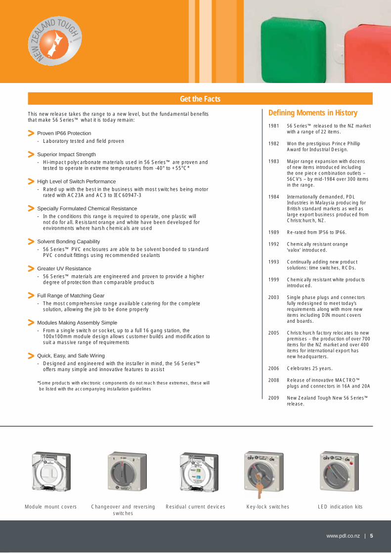
This new release takes the range to a new level, but the fundamental benefi ts that make 56 Series™ what it is today remain:
Proven IP66 Protection
- Laboratory tested and fi eld proven
Superior Impact Strength
- Hi-impact polycarbonate materials used in 56 Series™ are proven and tested to operate in extreme temperatures from -40° to +55°C*
High Level of Switch Performance
- Rated up with the best in the business with most switches being motor rated with AC23A and AC3 to IEC60947-3
Specially Formulated Chemical Resistance
- In the conditions this range is required to operate, one plastic will not do for all. Resistant orange and white have been developed for environments where harsh chemicals are used
Solvent Bonding Capability
- 56 Series™ PVC enclosures are able to be solvent bonded to standard PVC conduit fi ttings using recommended sealants
Greater UV Resistance
- 56 Series™ materials are engineered and proven to provide a higher degree of protection than comparable products
Full Range of Matching Gear
- The most comprehensive range available catering for the complete solution, allowing the job to be done properly
Modules Making Assembly Simple
- From a single switch or socket, up to a full 16 gang station, the 100x100mm module design allows customer builds and modifi cation to suit a massive range of requirements
Quick, Easy, and Safe Wiring
- Designed and engineered with the installer in mind, the 56 Series™ offers many simple and innovative features to assist
* Some products with electronic components do not reach these extremes, these will be listed with the accompanying installation guidelines
Module mount covers Changeover and reversing switches
Residual current devices Key-lock switches LED indication kits
1981 56 Series™ released to the NZ market with a range of 22 items.
1982 Won the prestigious Prince Phillip Award for Industrial Design.
1983 Major range expansion with dozens of new items introduced including the one piece combination outlets – 56CV’s – by mid-1984 over 300 items in the range.
1984 Internationally demanded, PDL Industries in Malaysia producing for British standard markets as well as large export business produced from Christchurch, NZ.
1989 Re-rated from IP56 to IP66.
1992 Chemically resistant orange ‘valox’ introduced.
1993 Continually adding new product solutions: time switches, RCDs.
1999 Chemically resistant white products introduced.
2003 Single phase plugs and connectors fully redesigned to meet today’s requirements along with more new items including DIN mount covers and boards.
2005 Christchurch factory relocates to new premises – the production of over 700 items for the NZ market and over 400 items for international export has new headquarters.
2006 Celebrates 25 years.
2008 Release of innovative MACTRO™ plugs and connectors in 16A and 20A
2009 New Zealand Tough New 56 Series™ release.
Defi ning Moments in History
Get the Facts

6 | www.pdl.co.nz
56 Series™...Rated No 1!
With features designed to outperform all other protected accessories
Total IP66 sealing fromconduit entry to plug cable
Channelled gaskets and high-pressure (HPG) gaskets for extreme environments
Screw caps eliminate dirt
LED (formerly neon) indicator option in switches (56SW and 56CV)
Clear indication of switch position
Padlock ON/OFF facility
Keylock switch option available in switches (56SW)
Rotary ON/OFF switch
Captive plate screws
Electrical rating and specification are clearly displayed
Available in high impact ‘electric grey’ or chemically resistant orange and white finishes
Transparent flap clearly shows pin configuration
19 ratings and pin configurations to AS/NZS3123
Plug locking ring maintainsIP66 protection while in use
Socket cover snaps shut automaticallyand locks to provide IP66 protection
Modular system for 1 to 16 gang arrangements
Socket auxiliary contacts for remote monitoring in a field fit kit
Redesigned socket flap - sockets open 43° further - 56CV’s open 8° further - increased strength - more access to plug rings - 36% less effort to open
Larger and easier to use latch design - better grip and operation
Pivot bungs removed - adds durability
Permanent laser engraved ratings - eliminates stickers and unidentified product
Increased padlocking area
Larger switch for easier operation
Contoured profile - reducing dust and dirt build-up
Angled switch handle - points towards switch position
Patented co-moulded gasket system - improved seal integrity
LED technology replacing neons in a field fit kit
Features and benefi ts with the NEW range...
Fundamental to the range 1981 to now...
www.pdl.co.nz | 7
This Edition
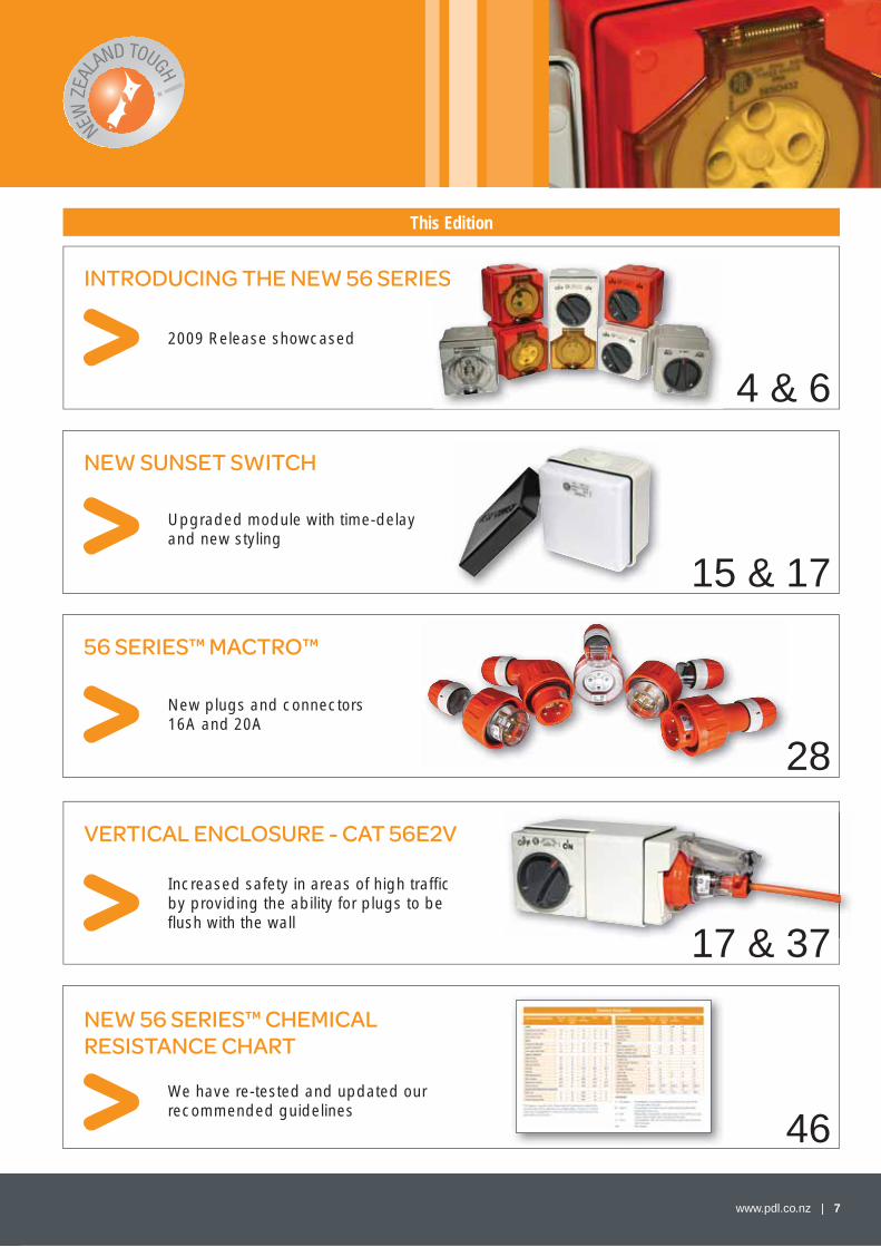
INTRODUCING THE NEW 56 SERIESES
4 & 62009 Release showcased
NEW SUNSET SWITCH
15 & 17
Upgraded module with time-delay and new styling
56 SERIES™ MACTRO™
28
New plugs and connectors 16A and 20A
VERTICAL ENCLOSURE - CAT 56E2V
17 & 37
Increased safety in areas of high traffi c by providing the ability for plugs to be fl ush with the wall
NEW 56 SERIES™ CHEMICAL RESISTANCE CHART
46We have re-tested and updated our recommended guidelines
8 | www.pdl.co.nz
Dimensional Drawings
Switches to IP66
240V Switches
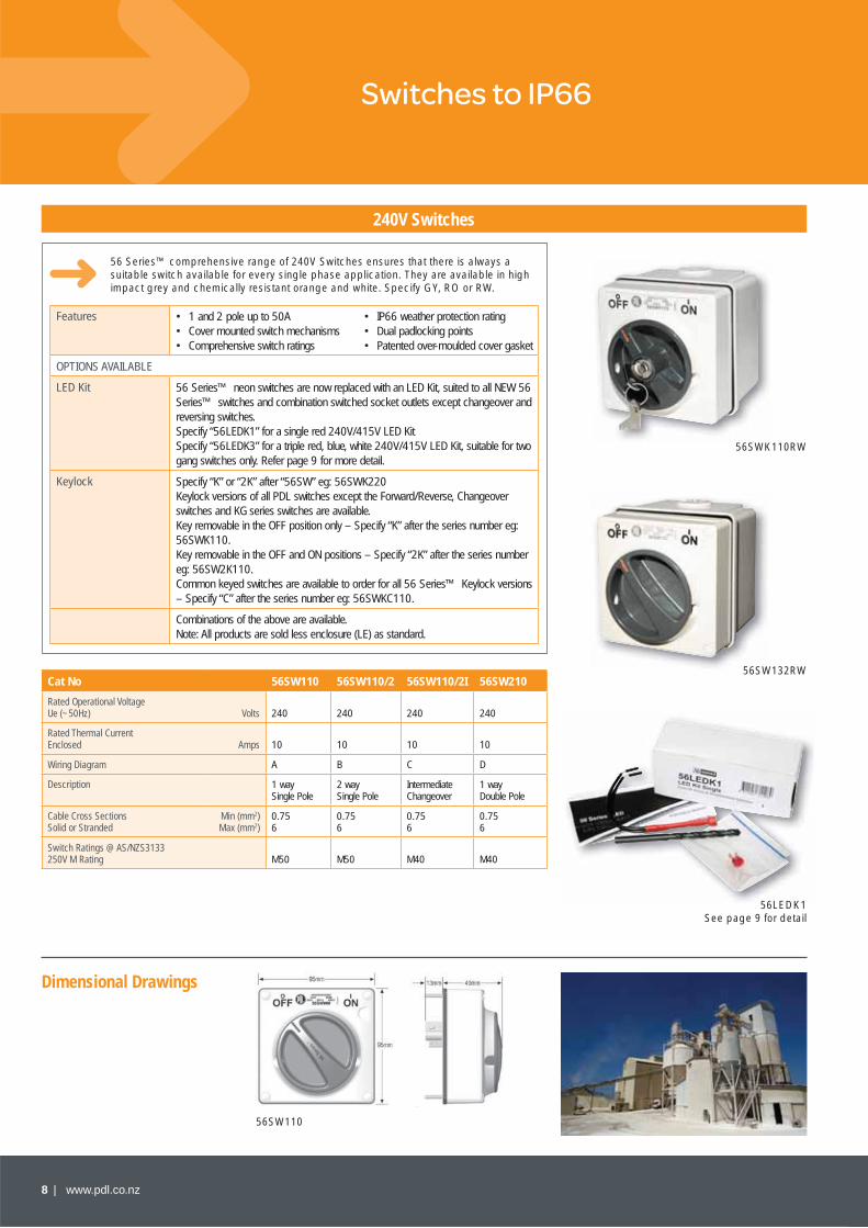
56SW110
56 Series™ comprehensive range of 240V Switches ensures that there is always a suitable switch available for every single phase application. They are available in high impact grey and chemically resistant orange and white. Specify GY, RO or RW.
Cat No 56SW110 56SW110/2 56SW110/2I 56SW210
Rated Operational Voltage Ue (~50Hz) Volts 240 240 240 240
Rated Thermal Current Enclosed Amps 10 10 10 10
Wiring Diagram A B C D
Description 1 way Single Pole
2 way Single Pole
Intermediate Changeover
1 way Double Pole
Cable Cross Sections Solid or Stranded
Min (mm2)Max (mm2)
0.756
0.756
0.756
0.756
Switch Ratings @ AS/NZS3133250V M Rating M50 M50 M40 M40
56SWK110RW
56SW132RW
56LEDK1See page 9 for detail
Features • 1 and 2 pole up to 50A • IP66 weather protection rating• Cover mounted switch mechanisms • Dual padlocking points• Comprehensive switch ratings • Patented over-moulded cover gasket
OPTIONS AVAILABLE
LED Kit 56 Series™ neon switches are now replaced with an LED Kit, suited to all NEW 56 Series™ switches and combination switched socket outlets except changeover and reversing switches. Specify “56LEDK1” for a single red 240V/415V LED KitSpecify “56LEDK3” for a triple red, blue, white 240V/415V LED Kit, suitable for two gang switches only. Refer page 9 for more detail.
Keylock Specify “K” or “2K” after “56SW” eg: 56SWK220 Keylock versions of all PDL switches except the Forward/Reverse, Changeover switches and KG series switches are available. Key removable in the OFF position only – Specify “K” after the series number eg: 56SWK110. Key removable in the OFF and ON positions – Specify “2K” after the series number eg: 56SW2K110. Common keyed switches are available to order for all 56 Series™ Keylock versions – Specify “C” after the series number eg: 56SWKC110.
Combinations of the above are available.Note: All products are sold less enclosure (LE) as standard.
www.pdl.co.nz | 9
Wiring Diagrams
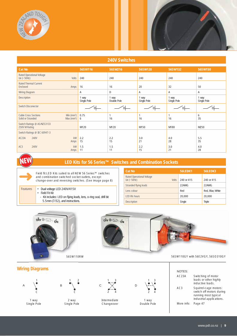
240V Switches
Cat No 56SW116 56SW216 56SW120 56SW132 56SW150
Rated Operational Voltage Ue (~50Hz) Volts 240 240 240 240 240
Rated Thermal Current Enclosed Amps 16 16 20 32 50
Wiring Diagram A D A A A
Description 1 way Single Pole
1 way Double Pole
1 way Single Pole
1 way Single Pole
1 way Single Pole
Switch Disconector
Cable Cross Sections Solid or Stranded
Min (mm2)Max (mm2)
0.756
116
116
116
635
Switch Ratings @ AS/NZS3133250V M Rating M120 M120 M150 M180 M250
Switch Ratings @ IEC 60947-3
AC23A 240V
AC3 240V
kWAmps
kWAmps
2.215
1.511
2.215
1.511
3.021
2.215
4.028
3.021
5.535
4.028
56SW110RW56SW110
NOTES:
AC23A Switching of motor loads or other highly inductive loads.
AC3 Squirrel-cage motors: switch off motors during running most typical industrial applications.
More info: Page 47
1
C C
A B C D
1 1 1
22
2 3 3
44
1 way Single Pole
2 way Single Pole
Intermediate Changeover
1 way Double Pole
Features • Dual voltage LED 240V/415V• Field Fit Kit
- Kit includes: LED on fl ying leads, lens, o-ring seal, drill bit 5.5mm (7/32), and instructions.
LED Kits for 56 Series™ Switches and Combination Sockets
Cat No 56LEDK1 56LEDK3
Rated Operational VoltageUe (~50Hz) Volts 240 or 415 240 or 415
Stranded fl ying leads 22AWG 22AWG
Lens colour Red Red, Blue, White
LED life hours 20,000 20,000
Description Single Triple
56SW110GY with 56E2VGY, 56SO310GY
Field fi t LED Kits suited to all NEW 56 Series™ switches and combination switched socket outlets, except change-over and reversing switches. (See image page 8)
10 | www.pdl.co.nz
Switches to IP66
Wiring Diagrams
Dimensional Drawings
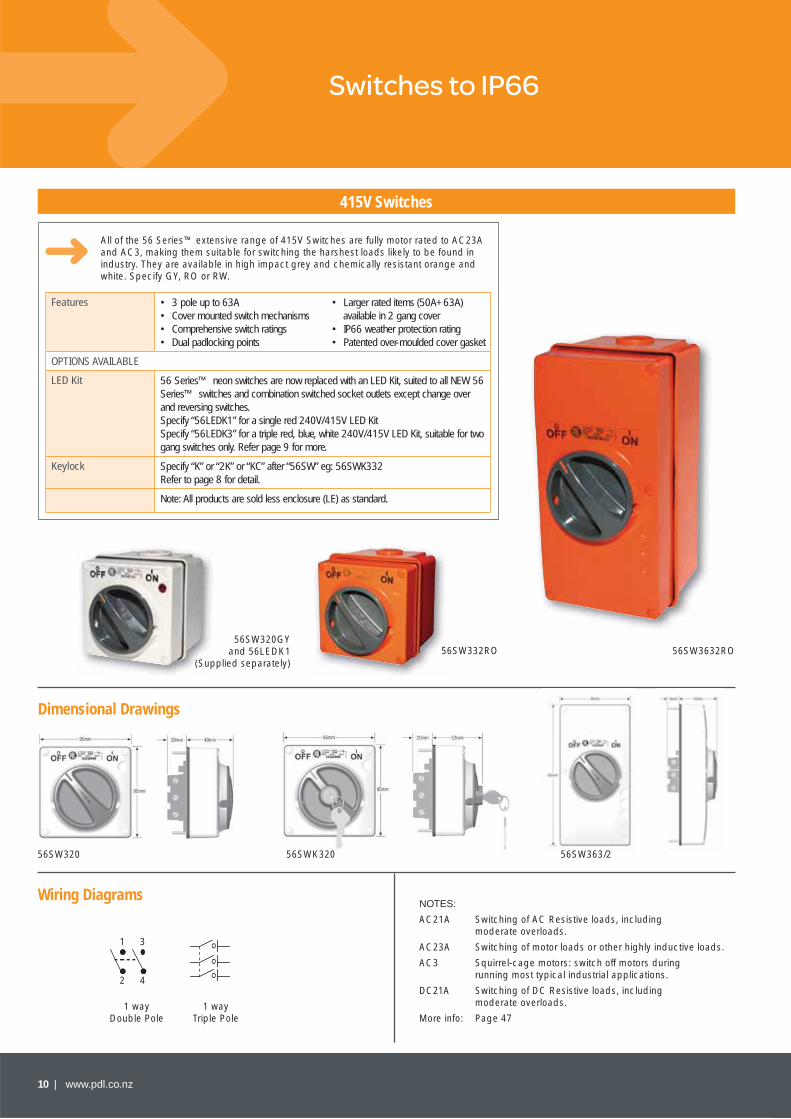
415V Switches
All of the 56 Series™ extensive range of 415V Switches are fully motor rated to AC23A and AC3, making them suitable for switching the harshest loads likely to be found in industry. They are available in high impact grey and chemically resistant orange and white. Specify GY, RO or RW.
Features • 3 pole up to 63A • Larger rated items (50A+63A)• Cover mounted switch mechanisms available in 2 gang cover• Comprehensive switch ratings • IP66 weather protection rating• Dual padlocking points • Patented over-moulded cover gasket
OPTIONS AVAILABLE
LED Kit 56 Series™ neon switches are now replaced with an LED Kit, suited to all NEW 56 Series™ switches and combination switched socket outlets except change over and reversing switches. Specify “56LEDK1” for a single red 240V/415V LED KitSpecify “56LEDK3” for a triple red, blue, white 240V/415V LED Kit, suitable for two gang switches only. Refer page 9 for more.
Keylock Specify “K” or “2K” or “KC” after “56SW” eg: 56SWK332Refer to page 8 for detail.
Note: All products are sold less enclosure (LE) as standard.
56SW320GYand 56LEDK1
(Supplied separately)56SW332RO
56SW320 56SWK320
1 way Triple Pole
1 way Double Pole
NOTES:
AC21A Switching of AC Resistive loads, including moderate overloads.
AC23A Switching of motor loads or other highly inductive loads.
AC3 Squirrel-cage motors: switch off motors during running most typical industrial applications.
DC21A Switching of DC Resistive loads, including moderate overloads.
More info: Page 47
56SW3632RO
56SW363/2
1
2
3
4
www.pdl.co.nz | 11
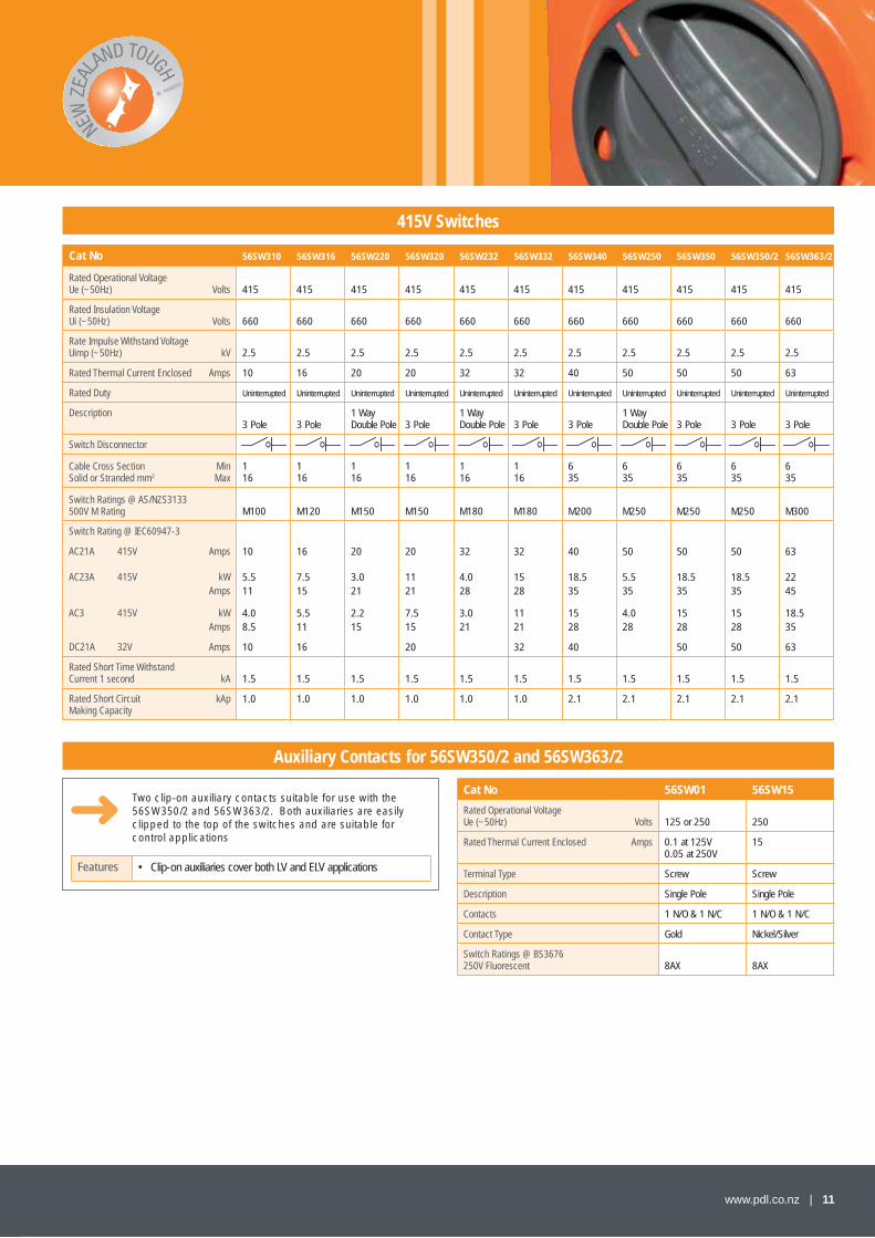
415V Switches
Cat No 56SW310 56SW316 56SW220 56SW320 56SW232 56SW332 56SW340 56SW250 56SW350 56SW350/2 56SW363/2
Rated Operational VoltageUe (~50Hz) Volts 415 415 415 415 415 415 415 415 415 415 415
Rated Insulation VoltageUi (~50Hz) Volts 660 660 660 660 660 660 660 660 660 660 660
Rate Impulse Withstand VoltageUimp (~50Hz) kV 2.5 2.5 2.5 2.5 2.5 2.5 2.5 2.5 2.5 2.5 2.5
Rated Thermal Current Enclosed Amps 10 16 20 20 32 32 40 50 50 50 63
Rated Duty Uninterrupted Uninterrupted Uninterrupted Uninterrupted Uninterrupted Uninterrupted Uninterrupted Uninterrupted Uninterrupted Uninterrupted Uninterrupted
Description3 Pole 3 Pole
1 Way Double Pole 3 Pole
1 Way Double Pole 3 Pole 3 Pole
1 Way Double Pole 3 Pole 3 Pole 3 Pole
Switch Disconnector
Cable Cross SectionSolid or Stranded mm2
MinMax
116
116
116
116
116
116
635
635
635
635
635
Switch Ratings @ AS/NZS3133500V M Rating M100 M120 M150 M150 M180 M180 M200 M250 M250 M250 M300
Switch Rating @ IEC60947-3
AC21A 415V
AC23A 415V
AC3 415V
DC21A 32V
Amps
kWAmps
kWAmps
Amps
10
5.511
4.08.5
10
16
7.515
5.511
16
20
3.021
2.215
20
1121
7.515
20
32
4.028
3.021
32
1528
1121
32
40
18.535
1528
40
50
5.535
4.028
50
18.535
1528
50
50
18.535
1528
50
63
2245
18.535
63
Rated Short Time Withstand Current 1 second kA 1.5 1.5 1.5 1.5 1.5 1.5 1.5 1.5 1.5 1.5 1.5
Rated Short Circuit Making Capacity
kAp 1.0 1.0 1.0 1.0 1.0 1.0 2.1 2.1 2.1 2.1 2.1
Two clip-on auxiliary contacts suitable for use with the 56SW350/2 and 56SW363/2. Both auxiliaries are easily clipped to the top of the switches and are suitable for control applications
Features • Clip-on auxiliaries cover both LV and ELV applications
Auxiliary Contacts for 56SW350/2 and 56SW363/2
Cat No 56SW01 56SW15
Rated Operational VoltageUe (~50Hz) Volts 125 or 250 250
Rated Thermal Current Enclosed Amps 0.1 at 125V0.05 at 250V
15
Terminal Type Screw Screw
Description Single Pole Single Pole
Contacts 1 N/O & 1 N/C 1 N/O & 1 N/C
Contact Type Gold Nickel/Silver
Switch Ratings @ BS3676 250V Fluorescent 8AX 8AX
12 | www.pdl.co.nz
Dimensional Drawings Wiring Diagrams
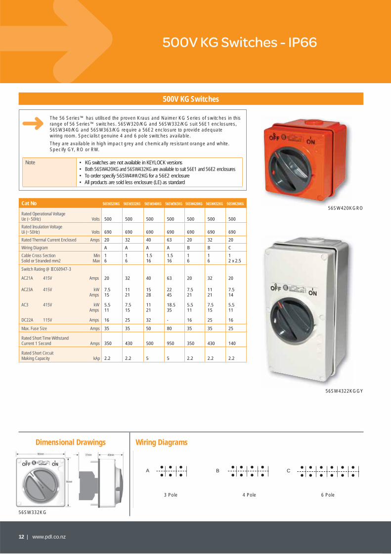
500V KG Switches - IP66
The 56 Series™ has utilised the proven Kraus and Naimer KG Series of switches in this range of 56 Series™ switches. 56SW320/KG and 56SW332/KG suit 56E1 enclosures, 56SW340/KG and 56SW363/KG require a 56E2 enclosure to provide adequate wiring room. Specialist genuine 4 and 6 pole switches available.
They are available in high impact grey and chemically resistant orange and white. Specify GY, RO or RW.
Note • KG switches are not available in KEYLOCK versions• Both 56SW420KG and 56SW432KG are available to suit 56E1 and 56E2 enclosures• To order specify 56SW4##/2KG for a 56E2 enclosure• All products are sold less enclosure (LE) as standard
56SW332KG
500V KG Switches
56SW420KGRO
56SW4322KGGY
A B C
3 Pole 4 Pole 6 Pole
Cat No 56SW320KG 56SW332KG 56SW340KG 56SW363KG 56SW420KG 56SW432KG 56SW620KG
Rated Operational VoltageUe (~50Hz) Volts 500 500 500 500 500 500 500
Rated Insulation VoltageUi (~50Hz) Volts 690 690 690 690 690 690 690
Rated Thermal Current Enclosed Amps 20 32 40 63 20 32 20
Wiring Diagram A A A A B B C
Cable Cross SectionSolid or Stranded mm2
MinMax
16
16
1.516
1.516
16
16
12 x 2.5
Switch Rating @ IEC60947-3
AC21A 415V
AC23A 415V
AC3 415V
DC22A 115V
Amps
kWAmps
kWAmps
Amps
20
7.515
5.511
16
32
1121
7.515
25
40
1528
1121
32
63
2245
18.535
-
20
7.521
5.511
16
32
1121
7.515
25
20
7.514
5.511
16
Max. Fuse Size Amps 35 35 50 80 35 35 25
Rated Short Time Withstand Current 1 Second Amps 350 430 500 950 350 430 140
Rated Short Circuit Making Capacity kAp 2.2 2.2 5 5 2.2 2.2 2.2

www.pdl.co.nz | 13
Dimensional Drawings Wiring Diagrams
Control Switches - IP66
A range of IP66 Changeover and Forward/Reverse switches ideal for generators, auto/manual systems, fans, doors and conveyors. Each switch comes with a sheet of adhesive labels for the end user to select the appropriate cover markings for the specifi c application. Cover markings possible include:
I, II FWD, REV MAN, AUTO AUX, MAIN UP, DOWN
Control Switches are supplied as a standard 100 x 100 one gang module less enclosure.
Features • IP66 rated• Comprehensive switch ratings
Note • Grey (GY), orange (RO), and white (RW) available• All products are sold less enclosure (LE) as standard• Not suitable for LED Kit
Changeover and Forward/Reverse Switches IP66
56SW320FRRO
56SW320COGY56SW320CO
56SW320FR
Cat No 56SW120CO 56SW320CO 56SW332CO 56SW320FR
Rated Operational VoltageUe (~50Hz) Volts 500 500 500 500
Rated Insulation VoltageUi (~50Hz) Volts 690 690 690 690
Rated Thermal Current Enclosed Amps 20 20 32 20
Description 1 PoleChangeover
3 PoleChangeover
3 PoleChangeover
3 PoleReversing
Wiring Diagram A B B C
Cable Cross SectionSolid or Stranded mm2 2 x 2.5 2 x 2.5 2 x 6 2 x 2.5
Switch Rating @ IEC60947-3
AC21A 500V
AC23A 415V 3 Phase 240V 1 Phase
AC3 415V 3 Phase 240V 1 Phase
AC4 415V 3 Phase 240V 1 Phase
DC21A 24V
DC22A 24V
Amps
kWkW
kWkW
kWkW
Amps
Amps
20
-2.5
-2.2
-0.75
20
12
20
7.5-
5.5-
1.5-
20
12
32
15-
11-
5.5-
32
25
20
7.5-
5.5-
1.5-
20
12
Max. Fuse Size Amps 25 25 35 25
Rated Short Time Withstand Current 1 Second Amps 140 140 480 140
Rated Short CircuitMaking Capacity kAp 5 5 5 5
56SW320FR & 56SW320CO
NOTES:
AC21A Switching of AC Resistive loads, including moderate overloads.
AC23A Switching of motor loads or other highly inductive loads.
AC3 Squirrel-cage motors: switch off motors during running most typical industrial applications.
AC4 Squirrel-cage motors: including reversing, plugging and inching.
DC21A Switching of DC Resistive loads, including moderate overloads.
DC22A Switching of inductive DC loads.
More info: Page 47
Single Pole Changeover Switch, Double
Throw with Centre Off
Triple Pole Changeover Switch, Double
Throw with Centre Off
Single Phase Reversing
Three Phase Reversing
14 | www.pdl.co.nz
Time Switches - IP66Momentary Contact Switches - IP66
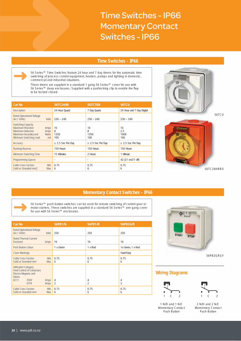
Time Switches - IP66
Momentary Contact Switches - IP66
56 Series™ Time Switches feature 24 hour and 7 day timers for the automatic time switching of process control equipment, heaters, pumps and lighting in domestic, commercial and industrial situations.
These timers are supplied in a standard 1 gang 56 Series™ cover for use with 56 Series™ deep enclosures. Supplied with a padlocking clip to enable the fl ap to be locked closed.
56 Series™ push button switches can be used for remote switching of control gear or motor starters. These switches are supplied in a standard 56 Series™ one gang cover for use with 56 Series™ enclosures.
Cat No 56TC24HB 56TC7DB 56TCU
Description 24 Hour Quartz 7 Day Quartz 24 Hour and 7 Day Digital
Rated Operational VoltageUe (~50Hz) Volts 230 – 240 230 – 240 230 – 240
Switching CapacityMaximum ResistiveMaximum InductiveMaximum IncandescentMinimum Switching Load
AmpsAmpsWatts
mA
1681350100
1681350100
162.51000100
Accuracy ± 2.5 Sec Per Day ± 2.5 Sec Per Day ± 2.5 Sec Per Day
Running Reserve 150 Hours 150 Hours 150 Hours
Minimum Switching Time 15 Minutes 2 Hours 1 Minute
Programming Spaces - - 42 (21 on/21 off)
Cable Cross SectionSolid or Stranded mm2
MinMax
0.756
0.756
0.756
Cat No 56PB1/G 56PB1/R 56PB2G/R
Rated Operational VoltageUe (~50Hz) Volts 250 250 250
Rated Thermal CurrentEnclosed Amps 16 16 16
Push Button Colour 1 x Green 1 x Red 1x Green, 1 x Red
Cover Markings Start/Stop
Cable Cross SectionSolid or Stranded mm2
MinMax
0.756
0.756
0.756
Utilisation CategoryFeed Control of ContactorsElectro-Magnets and ValvesAC11 250V 415V
AmpsAmps
42
42
42
Cable Cross SectionSolid or Stranded mm2
MinMax
0.756
0.756
0.756
56TCU
56TC24HBRO
56PB2GRGY
Wiring Diagrams
1 N/O and 1 N/C Momentary Contact
Push Button
2 N/O and 2 N/CMomentary Contact
Push Button
1 1C C2 2
www.pdl.co.nz | 15
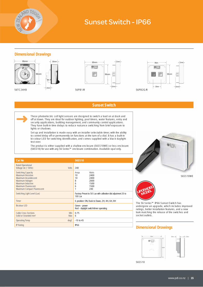
Sunset Switch - IP66
Sunset Switch
These photoelectric cell light sensors are designed to switch a load on at dusk and off at dawn. They are ideal for outdoor lighting, pool timers, water features, entry and security applications, building management, and community control applications. They have built-in time delays to reduce nuisance switching from brief exposure to lights or shadows.
Set up and installation is made easy with an installer selectable timer, with the ability to control delay off or permanently on functions at the turn of a dial. It has a built-in bi-colour LED for switching identifi cation, and comes supplied with a black daylight test over.
The product is either supplied with a shallow enclosure (56SS10WE) or less enclosure (56SS10) for use with any 56 Series™ enclosure combination. Available opal only.
Cat No 56SS10
Rated OperationalVoltage Ue (~50Hz) Volts 240
Switching CapacityMaximum ResistiveMaximum IncandescentMaximum HalogenMaximum InductiveMaximum FluorescentMaximum Compact Fluorescent
Amps Watts10 240010 24008 20006 15006 15001 240
Switching Light Level (Lux) Factory Preset to 50 Lux with calibration dial adjustment 20 to 100 Lux
Timer 6 position: ON, Dusk to Dawn, 2H, 4H, 6H, 8H
Bicolour LED Green - power Red - daylight switch/timer operating
Cable Cross SectionsSolid or Stranded mm2
MinMax
0.756
Operating Temp degC -10 to 45
IP Rating IP66
Dimensional Drawings
95mm
95mm
24mm
35mm 28mm
20mm
95mm
95mm
95m
95mm
20mm
28mm
20mm
56TC24HB 56PB1/R 56PB2G/R
56SS10WE
56SS10
Dimensional Drawings
The 56 Series™ IP66 Sunset Switch has undergone an upgrade, which includes improved ratings, better installation features, and a new look matching the release of the switches and socket outlets.
32mm 32mm
30mm
UPGRADED
MODEL
Dimensional Drawings
16 | www.pdl.co.nz
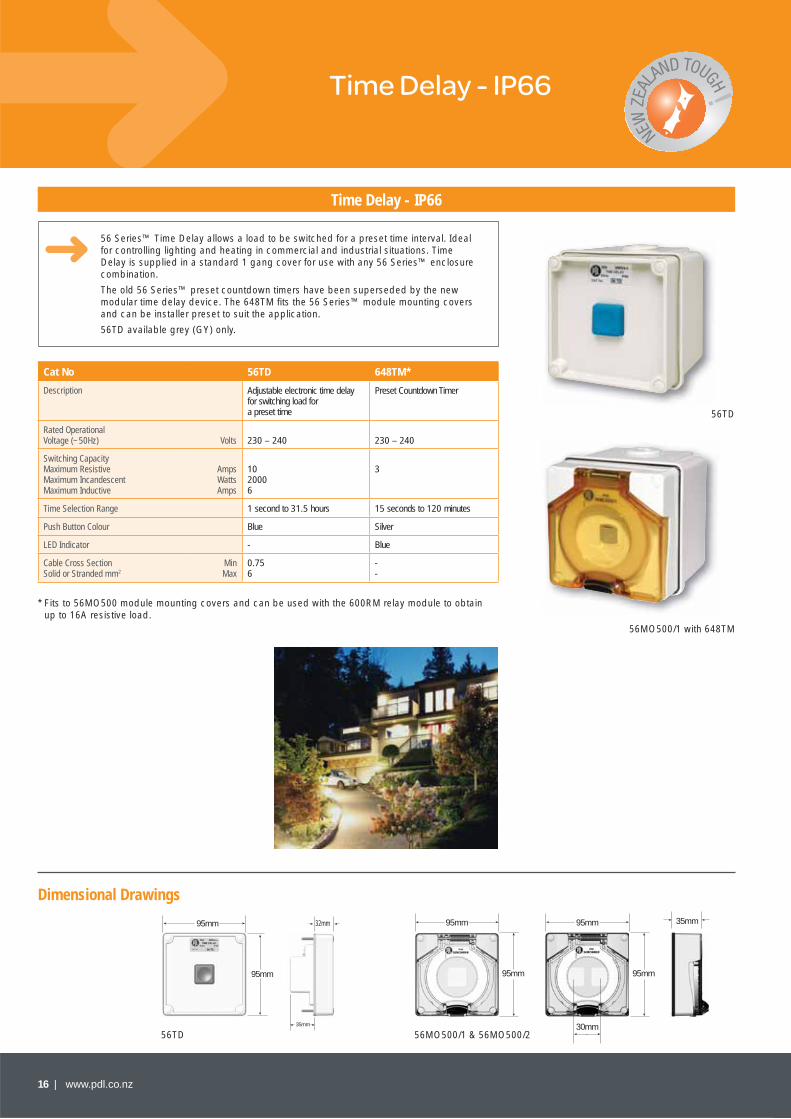
Time Delay - IP66
Time Delay - IP66
56 Series™ Time Delay allows a load to be switched for a preset time interval. Ideal for controlling lighting and heating in commercial and industrial situations. Time Delay is supplied in a standard 1 gang cover for use with any 56 Series™ enclosure combination.
The old 56 Series™ preset countdown timers have been superseded by the new modular time delay device. The 648TM fi ts the 56 Series™ module mounting covers and can be installer preset to suit the application.
56TD available grey (GY) only.
95mm
95mm
28mm
35mm
56TD
56TD
56MO500/1 with 648TM
* Fits to 56MO500 module mounting covers and can be used with the 600RM relay module to obtain up to 16A resistive load.
Cat No 56TD 648TM*
Description Adjustable electronic time delay for switching load for a preset time
Preset Countdown Timer
Rated Operational Voltage (~50Hz) Volts 230 – 240 230 – 240
Switching CapacityMaximum ResistiveMaximum IncandescentMaximum Inductive
AmpsWattsAmps
1020006
3
Time Selection Range 1 second to 31.5 hours 15 seconds to 120 minutes
Push Button Colour Blue Silver
LED Indicator - Blue
Cable Cross SectionSolid or Stranded mm2
MinMax
0.756
--
95mm
95mm
35mm
95mm
95mm
30mm
35mm
56MO500/1 & 56MO500/2
32mm

• The upgraded 56 Series™ Sunset Switch• Improved performance• Better ratings• Enhanced installer and user options• Introduced November 2009
At the end of the day... 56 Series™ was the winner
www.pdl.co.nz | 17
Think outside the box and standardise on safety
The innovative 56 Series™ mounting enclosure that allows plugs to sit fl ush with the wall
Improved safety in high-traffi c and hazardous areas
Fits any two single-gang 56 Series™ products
Specify the Cat 56E2V vertical enclosure into your electrical installation
New ratings: 10A resistive,
8A halogen, 6A inductive, 6A fl uorescent,
240W compact fl uorescent
For further information, please contact Customer Care on 0800 652 999 or visit www.pdl.co.nz
For further information, please contact Customer Care on 0800 652 999 or visit www.pdl.co.nz

18 | www.pdl.co.nz
Dimensional Drawings
Socket Outlets - IP66
110 - 250V Socket Outlets
56 Series™ 110 – 250V Socket Outlets feature a transparent hinged fl ap which snaps shut and locks over the socket when the plug is withdrawn, forming an automatic IP66 seal. The fl ap is transparent so the pin confi guration can be readily identifi ed without opening.
They are available in high impact grey and chemically resistant orange and white. Specify GY, RO or RW.
Note: All products are sold less enclosure (LE) as standard.
Cat No 56SO310 56SO310/2 56SO310R 56SO310A 56SO315 56SO315A 56SO320F
Rated Operational Voltage Ue (~50Hz) Volts 250 250 250 250 250 250 250
Rated Thermal Current Enclosed Amps 10 10 10 10 15 15 20
Number of Socket Pins(Including Earth )
3 (Flat) 3 (Flat) 3 (2 Flat & Round Earth)
3 (Flat) 3 (Flat) 3 (Flat) 3 (Flat)
Description NZ/Aust NZ/Aust Twin Socket
NZ/Aust Round Earth
NZ/Aust Auto Switched Double Pole
NZ/Aust NZ/Aust Auto Switched Double Pole
NZ/Aust 3 Large FlatPin
Socket Confi guration refer Pg 55 A A B A D D E
Cable Cross SectionsSolid or Stranded mm2
MinMax
0.7510
0.7510
0.7510
0.7510
0.7510
0.7510
0.7510
IP Rating IP66 IP66 IP66 IP66 IP66 IP66 IP66
Cat No 56SO316/110 56SO316/240 56SO320 56SO332
Rated Operational Voltage Ue (~50Hz) Volts 110 Yellow 230 Blue 250 250
Rated Thermal Current Enclosed Amps 16 16 20 32
Number of Socket Pins (Including Earth )
3 (Round) 3 (Round) 3 (Round) 3 (Round)
Description CEE17 - 4h CEE17 - 6h AS/NZS3123 AS/NZS3123
Socket Confi guration refer Pg 55 V W F G
Cable Cross SectionsSolid or Stranded mm2
MinMax
0.756
0.756
1.010
1.016
IP Rating IP66 IP66 IP66 IP66
56SO310RW
56SO310/2RO
56SO316240GY
NOTES:
For pin confi gurations refer to inside back cover – 56 Series™ Product Master – Page 55
95mm
95mm
35mm
25mm
56SO310
95mm
190mm
25mm
35mm
56SO310/2
www.pdl.co.nz | 19
Dimensional Drawings
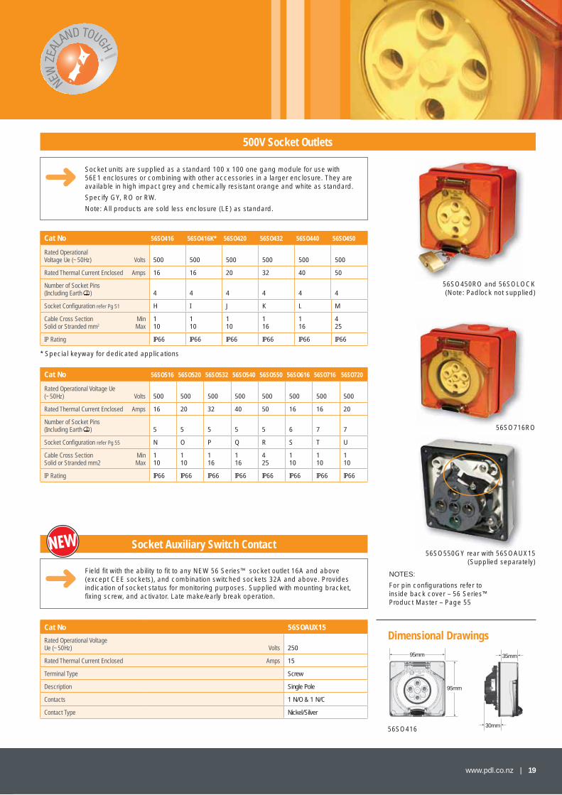
500V Socket Outlets
Socket units are supplied as a standard 100 x 100 one gang module for use with 56E1 enclosures or combining with other accessories in a larger enclosure. They are available in high impact grey and chemically resistant orange and white as standard.
Specify GY, RO or RW.
Note: All products are sold less enclosure (LE) as standard.
Cat No 56SO416 56SO416K* 56SO420 56SO432 56SO440 56SO450
Rated Operational Voltage Ue (~50Hz) Volts 500 500 500 500 500 500
Rated Thermal Current Enclosed Amps 16 16 20 32 40 50
Number of Socket Pins (Including Earth ) 4 4 4 4 4 4
Socket Confi guration refer Pg 51 H I J K L M
Cable Cross SectionSolid or Stranded mm2
MinMax
110
110
110
116
116
425
IP Rating IP66 IP66 IP66 IP66 IP66 IP66
Cat No 56SO516 56SO520 56SO532 56SO540 56SO550 56SO616 56SO716 56SO720
Rated Operational Voltage Ue (~50Hz) Volts 500 500 500 500 500 500 500 500
Rated Thermal Current Enclosed Amps 16 20 32 40 50 16 16 20
Number of Socket Pins (Including Earth ) 5 5 5 5 5 6 7 7
Socket Confi guration refer Pg 55 N O P Q R S T U
Cable Cross SectionSolid or Stranded mm2
MinMax
110
110
116
116
425
110
110
110
IP Rating IP66 IP66 IP66 IP66 IP66 IP66 IP66 IP66
56SO450RO and 56SOLOCK(Note: Padlock not supplied)
56SO716RO
NOTES:
For pin confi gurations refer to inside back cover – 56 Series™ Product Master – Page 55
56SO716
* Special keyway for dedicated applications
35mm
30mm
95mm
95mm
56SO416
56SO550GY rear with 56SOAUX15(Supplied separately)
Field fi t with the ability to fi t to any NEW 56 Series™ socket outlet 16A and above (except CEE sockets), and combination switched sockets 32A and above. Provides indication of socket status for monitoring purposes. Supplied with mounting bracket, fi xing screw, and activator. Late make/early break operation.
Socket Auxiliary Switch Contact
Cat No 56SOAUX15
Rated Operational VoltageUe (~50Hz) Volts 250
Rated Thermal Current Enclosed Amps 15
Terminal Type Screw
Description Single Pole
Contacts 1 N/O & 1 N/C
Contact Type Nickel/Silver
20 | www.pdl.co.nz
Dimensional Drawings
CEE17 Socket Outlets - IP57
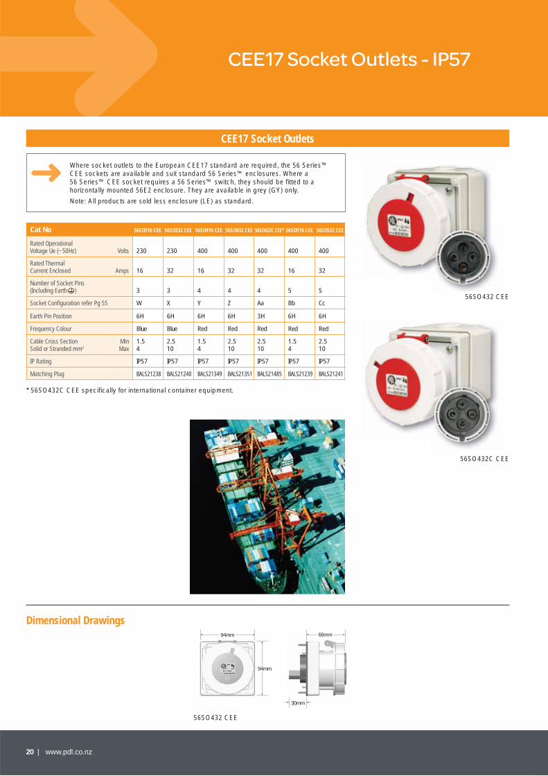
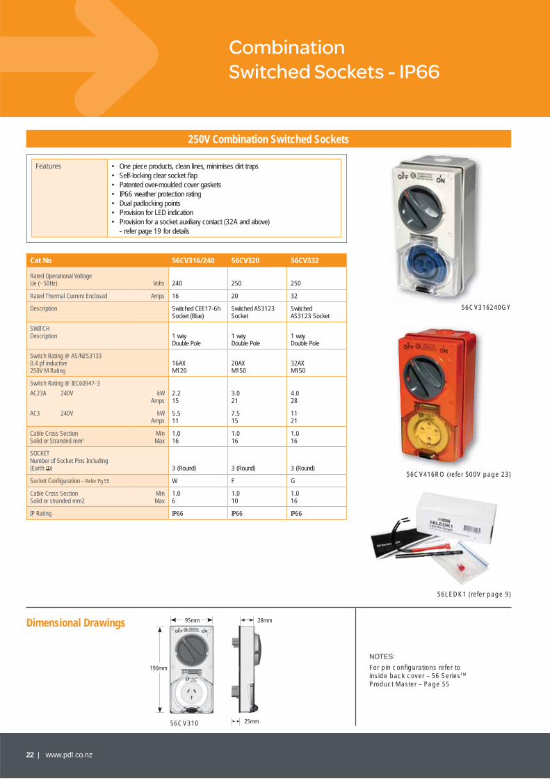
CEE17 Socket Outlets
Where socket outlets to the European CEE17 standard are required, the 56 Series™ CEE sockets are available and suit standard 56 Series™ enclosures. Where a 56 Series™ CEE socket requires a 56 Series™ switch, they should be fi tted to a horizontally mounted 56E2 enclosure. They are available in grey (GY) only.
Note: All products are sold less enclosure (LE) as standard.
Cat No 56SO316 CEE 56SO332 CEE 56SO416 CEE 56SO432 CEE 56SO432C CEE* 56SO516 CEE 56SO532 CEE
Rated OperationalVoltage Ue (~50Hz) Volts 230 230 400 400 400 400 400
Rated Thermal Current Enclosed Amps 16 32 16 32 32 16 32
Number of Socket Pins (Including Earth ) 3 3 4 4 4 5 5
Socket Confi guration refer Pg 55 W X Y Z Aa Bb Cc
Earth Pin Position 6H 6H 6H 6H 3H 6H 6H
Frequency Colour Blue Blue Red Red Red Red Red
Cable Cross SectionSolid or Stranded mm2
MinMax
1.54
2.510
1.54
2.510
2.510
1.54
2.510
IP Rating IP57 IP57 IP57 IP57 IP57 IP57 IP57
Matching Plug BALS21238 BALS21240 BALS21349 BALS21351 BALS21485 BALS21239 BALS21241
56SO432 CEE
56SO432C CEE
* 56SO432C CEE specifi cally for international container equipment.
66mm
30mm
94mm
94mm
56SO432 CEE

www.pdl.co.nz | 21
Combination Switched Sockets - IP66
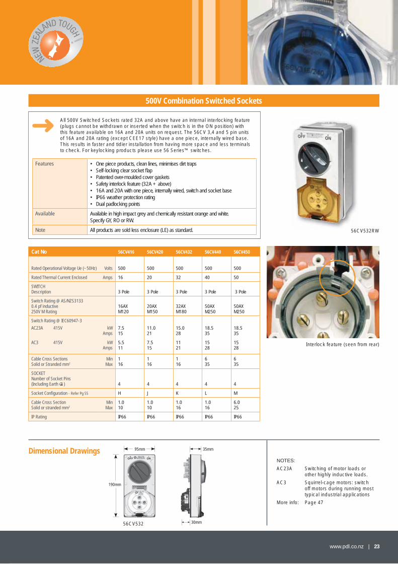
250V Combination Switched Sockets
The 56 SeriesTM includes an extensive range of one piece combination Switched Sockets.
They are available in high impact grey, and chemically resistant orange and white as standard. Specify GY, RO or RW.
Cat No 56CV310 56CV315
Rated Operational Voltage Ue (~50Hz) Volts 250 250
Rated Thermal Current Enclosed Amps 10 15
Description Switched NZ/Aust. Socket
Switched NZ/Aust. Socket
SWITCHDescription 1 way
Single Pole1 way Double Pole
Switch Rating @ AS/NZS3133 0.4 pf inductive 250V M Rating
10AX M50
16AX M120
Switch Rating @ IEC60947-3 AC23A 240V kW
Amps 2.215
2.215
Cable Cross SectionSolid or Stranded mm2
MinMax
0.756
1.016
SOCKETNumber of Socket Pins Including (Earth ) 3 (Flat) 3 (Flat)
Socket Confi guration - Refer Pg 55 A D
Cable Cross SectionSolid or Stranded mm2
MinMax
1.010
1.010
IP Rating IP66 IP66
56CV310RW and 56LEDK1(Supplied separately)
56CV420GY and 56PA420QC
(refer 500V page 23)
56CVand 56PA
(refer 500V p
Features • One piece products, clean lines, minimises dirt traps• Self-locking clear socket fl ap• Patented over moulded cover gaskets• IP66 weather protection rating• Dual padlocking points• Provision for LED indication
Note • For keylocking products, please use 56 Series™ switches• All products are sold less enclosure (LE) as standard
Dimensional Drawings
56CV310
35mm
25mm
95mm
190mm
NOTES:
For pin confi gurations refer to inside back cover – 56 Series™ Product Master – Page 55
AC23A Switch of motor loads or other highly inductive loads.
More info: Page 47
22 | www.pdl.co.nz
Dimensional Drawings
Combination Switched Sockets - IP66
250V Combination Switched Sockets
Cat No 56CV316/240 56CV320 56CV332
Rated Operational Voltage Ue (~50Hz) Volts 240 250 250
Rated Thermal Current Enclosed Amps 16 20 32
Description Switched CEE17-6h Socket (Blue)
Switched AS3123 Socket
Switched AS3123 Socket
SWITCH Description 1 way
Double Pole1 way Double Pole
1 way Double Pole
Switch Rating @ AS/NZS31330.4 pf inductive 250V M Rating
16AX M120
20AX M150
32AX M150
Switch Rating @ IEC60947-3
AC23A 240V
AC3 240V
kWAmps
kWAmps
2.215
5.511
3.021
7.515
4.028
1121
Cable Cross SectionSolid or Stranded mm2
MinMax
1.016
1.016
1.016
SOCKET Number of Socket Pins Including (Earth ) 3 (Round) 3 (Round) 3 (Round)
Socket Confi guration - Refer Pg 55 W F G
Cable Cross SectionSolid or stranded mm2
MinMax
1.06
1.010
1.016
IP Rating IP66 IP66 IP66
Features • One piece products, clean lines, minimises dirt traps• Self-locking clear socket fl ap• Patented over-moulded cover gaskets• IP66 weather protection rating• Dual padlocking points• Provision for LED indication• Provision for a socket auxiliary contact (32A and above)
- refer page 19 for details
56CV316240GY
56CV416RO (refer 500V page 23)
56LEDK1 (refer page 9)
NOTES:
For pin confi gurations refer to inside back cover – 56 SeriesTM
Product Master – Page 55
56CV310
28mm
25mm
95mm
190mm
www.pdl.co.nz | 23
Dimensional Drawings
500V Combination Switched Sockets
Cat No 56CV416 56CV420 56CV432 56CV440 56CV450
Rated Operational Voltage Ue (~50Hz) Volts 500 500 500 500 500
Rated Thermal Current Enclosed Amps 16 20 32 40 50
SWITCHDescription 3 Pole 3 Pole 3 Pole 3 Pole 3 Pole
Switch Rating @ AS/NZS31330.4 pf inductive 250V M Rating
16AX M120
20AX M150
32AX M180
50AX M250
50AX M250
Switch Rating @ IEC60947-3
AC23A 415V
AC3 415V
kWAmps
kWAmps
7.515
5.511
11.021
7.515
15.028
1121
18.535
1528
18.535
1528
Cable Cross SectionsSolid or Stranded mm2
MinMax
116
116
116
635
635
SOCKET Number of Socket Pins (Including Earth ) 4 4 4 4 4
Socket Confi guration - Refer Pg 55 H J K L M
Cable Cross SectionSolid or stranded mm2
MinMax
1.010
1.010
1.016
1.016
6.025
IP Rating IP66 IP66 IP66 IP66 IP66
56CV532
NOTES:
AC23A Switching of motor loads or other highly inductive loads.
AC3 Squirrel-cage motors: switch off motors during running most typical industrial applications
More info: Page 47
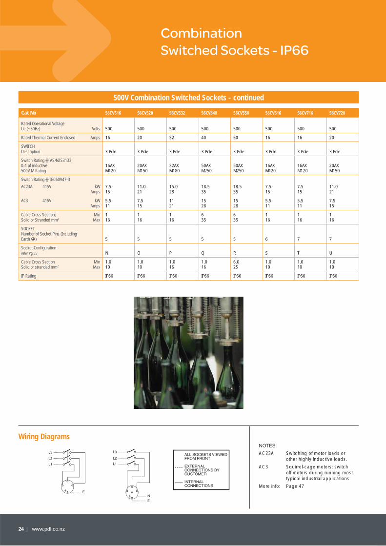
All 500V Switched Sockets rated 32A and above have an internal interlocking feature (plugs cannot be withdrawn or inserted when the switch is in the ON position) with this feature available on 16A and 20A units on request. The 56CV 3,4 and 5 pin units of 16A and 20A rating (except CEE17 style) have a one piece, internally wired base. This results in faster and tidier installation from having more space and less terminals to check. For keylocking products please use 56 Series™ switches.
Features • One piece products, clean lines, minimises dirt traps• Self-locking clear socket fl ap• Patented over-moulded cover gaskets• Safety interlock feature (32A + above)• 16A and 20A with one piece, internally wired, switch and socket base• IP66 weather protection rating• Dual padlocking points
Available Available in high impact grey and chemically resistant orange and white. Specify GY, RO or RW.
Note All products are sold less enclosure (LE) as standard. 56CV532RW
Interlock feature (seen from rear)
35mm
30mm
95mm
190mm
24 | www.pdl.co.nz
Wiring Diagrams
Combination Switched Sockets - IP66
500V Combination Switched Sockets - continued
Cat No 56CV516 56CV520 56CV532 56CV540 56CV550 56CV616 56CV716 56CV720
Rated Operational Voltage Ue (~50Hz) Volts 500 500 500 500 500 500 500 500
Rated Thermal Current Enclosed Amps 16 20 32 40 50 16 16 20
SWITCH Description 3 Pole 3 Pole 3 Pole 3 Pole 3 Pole 3 Pole 3 Pole 3 Pole
Switch Rating @ AS/NZS3133 0.4 pf inductive500V M Rating
16AXM120
20AXM150
32AXM180
50AXM250
50AXM250
16AXM120
16AXM120
20AXM150
Switch Rating @ IEC60947-3
AC23A 415V
AC3 415V
kWAmps
kWAmps
7.5 15
5.511
11.0 21
7.515
15.0 28
1121
18.5 35
1528
18.5 35
1528
7.5 15
5.511
7.5 15
5.511
11.0 21
7.515
Cable Cross SectionsSolid or Stranded mm2
MinMax
116
116
116
635
635
116
116
116
SOCKET Number of Socket Pins (Including Earth ) 5 5 5 5 5 6 7 7
Socket Confi guration refer Pg 55 N O P Q R S T U
Cable Cross SectionSolid or stranded mm2
MinMax
1.010
1.010
1.016
1.016
6.025
1.010
1.010
1.010
IP Rating IP66 IP66 IP66 IP66 IP66 IP66 IP66 IP66
NOTES:
AC23A Switching of motor loads or other highly inductive loads.
AC3 Squirrel-cage motors: switch off motors during running most typical industrial applications
More info: Page 47

www.pdl.co.nz | 25
Dimensional Drawings
RCD Protected Outlets - IP66
RCD Protected Outlets - IP66
Cat No 56RCD2030 56C310RCD30 56C316RCD30 56C320RCD30
Rated Operational Voltage Ue (~50Hz) Volts 240 240 240 240
Rated Thermal Current Enclosed Amps 20 10 16 20
Description RCD Module only RCD Protected 10A Socket
RCD Protected CEE17 Socket (Blue)
RCD Protected 20A Socket
RCD MODULE Rated Tripping CurrentRated Tripping Time (approximate)
30mA 30mS
30mA 30mS
30mA 30mS
30mA 30mS
SOCKET Number of Socket Pins (Including Earth ) 3 3 3
Socket Confi guration refer Pg 55 A W F
Cable Cross SectionSolid or Stranded mm2
MinMax
1.010
1.06
1.06
1.010
IP Rating IP66 IP66 IP66 IP66
56 Series™ RCD protected socket outlets protect the user against an earth fault. They feature double pole switching and respond to earth fault in pulsating DC applications. 56 Series™ RCDs are available with both latching and non-latching RCD modules.
To order a non-latching product specify ‘A’ in the description (ie. 56ARCD20).
To order a latching product refer to the descriptions below.
Features • 30mA rated tripping current for personal protection• IP66 weather protection rating• Self-locking cover fl ap• Double pole switching• Power consumption 16W at 240V
Available Available in high impact grey and chemically resistant orange and white. Specify GY, RO or RW.
Note All products are sold less enclosure (LE) as standard.Not available in 10mA.
NOTES:
For pin confi gurations refer to inside back cover – 56 Series™ Product Master – Page 55
56RCD2030GY
56C310RCD30RO and 56MF(Supplied separately)
56C310RCD30GY
56C310RCD30
35mm
30mm
95mm
190mm
26 | www.pdl.co.nz
Dimensional Drawings
RCD Protected Outlets - IP66
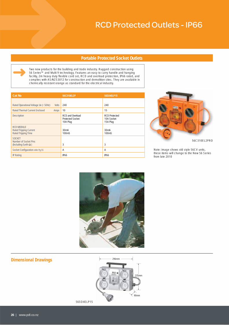
Portable Protected Socket Outlets
Cat No 56C310EL2P 56S04ELP15
Rated Operational Voltage Ue (~50Hz) Volts 240 240
Rated Thermal Current Enclosed Amps 10 15
Description RCD and Overload Protected Socket 10A Plug
RCD Protected 10A Socket 15A Plug
RCD MODULE Rated Tripping CurrentRated Tripping Time
30mA 100mS
30mA 100mS
SOCKET Number of Socket Pins (Including Earth ) 3 3
Socket Confi guration refer Pg 55 A A
IP Rating IP66 IP66
Two new products for the building and trade industry. Rugged construction using 56 Series™ and Multi 9 technology. Features an easy to carry handle and hanging facility, 2m heavy duty fl exible cord set, RCD and overload protection, IP66 rated, and complies with AS/NZS3012 for construction and demolition sites. They are available in chemically resistant orange as standard for the electrical industry.
56C310EL2PRO
296mm
235mm
90mm
56SO4ELP15
Note: image shows old style 56CV units, these items will change to the New 56 Series from late 2010
www.pdl.co.nz | 27
Dimensional Drawings
Appliance Inlets - IP66
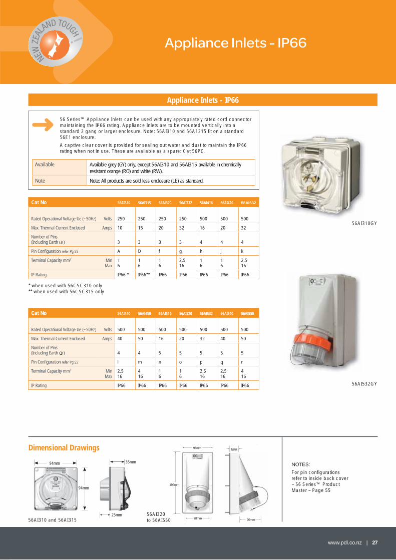
Appliance Inlets - IP66
56AI310GY
56AI532GY
56 Series™ Appliance Inlets can be used with any appropriately rated cord connector maintaining the IP66 rating. Appliance Inlets are to be mounted vertically into a standard 2 gang or larger enclosure. Note: 56AI310 and 56A1315 fi t on a standard 56E1 enclosure.
A captive clear cover is provided for sealing out water and dust to maintain the IP66 rating when not in use. These are available as a spare: Cat 56PC.
Available Available grey (GY) only, except 56AI310 and 56AI315 available in chemically resistant orange (RO) and white (RW).
Note Note: All products are sold less enclosure (LE) as standard.
Cat No 56AI310 56AI315 56Ai320 56AI332 56AI416 56AI420 56AI532
Rated Operational Voltage Ue (~50Hz) Volts 250 250 250 250 500 500 500
Max. Thermal Current Enclosed Amps 10 15 20 32 16 20 32
Number of Pins (Including Earth ) 3 3 3 3 4 4 4
Pin Confi guration refer Pg 55 A D f g h j k
Terminal Capacity mm2 MinMax
16
16
16
2.516
16
16
2.516
IP Rating IP66 * IP66** IP66 IP66 IP66 IP66 IP66
Cat No 56AI440 56AI450 56AI516 56AI520 56AI532 56AI540 56AI550
Rated Operational Voltage Ue (~50Hz) Volts 500 500 500 500 500 500 500
Max. Thermal Current Enclosed Amps 40 50 16 20 32 40 50
Number of Pins (Including Earth ) 4 4 5 5 5 5 5
Pin Confi guration refer Pg 55 l m n o p q r
Terminal Capacity mm2 MinMax
2.516
416
16
16
2.516
2.516
416
IP Rating IP66 IP66 IP66 IP66 IP66 IP66 IP66
28mm
70mm
192mm
95mm
78mm
* when used with 56CSC310 only** when used with 56CSC315 only
NOTES:
For pin confi gurations refer to inside back cover – 56 Series™ Product Master – Page 55
56AI310 and 56AI31556AI320 to 56AI550
35mm
25mm
94mm
94mm
32mm
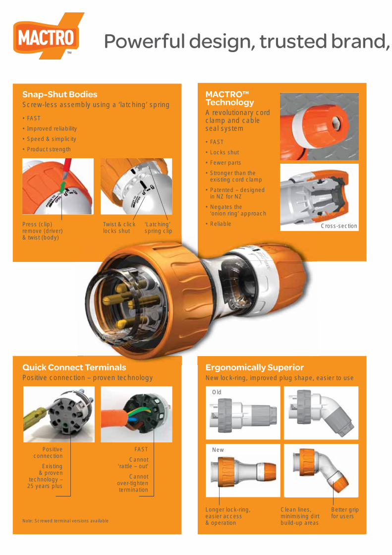
Powerful design, trusted brand,
Cross-section Press (clip)remove (driver) & twist (body)
Twist & clicklocks shut
‘Latching’ spring clip
MACTRO™TechnologyA revolutionary cord clamp and cable seal system
• FAST
• Locks shut
• Fewer parts
• Stronger than the existing cord clamp
• Patented – designed in NZ for NZ
• Negates the ‘onion ring’ approach
• Reliable
Quick Connect TerminalsPositive connection – proven technology
Ergonomically SuperiorNew lock-ring, improved plug shape, easier to use
Positive connection
Existing & proven
technology – 25 years plus
FAST
Cannot ‘rattle – out’
Cannot over-tighten termination
Note: Screwed terminal versions available
Longer lock-ring, easier access & operation
Clean lines, minimising dirt build-up areas
Better grip for users
New
Old
Snap-Shut BodiesScrew-less assembly using a ‘latching’ spring
• FAST
• Improved reliability
• Speed & simplicity
• Product strength
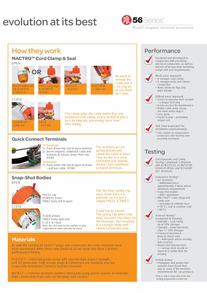
evolution at its best
How they work
Materials
Designed and developed in conjunction with practising electrical contractors, as well as dozens of factory visits reviewing usage and user requirements.
Weak areas improved:• A stronger cord clamp• A stronger body and sleeve
connection• New connector fl ap and
latch design
Diffi cult areas improved:• Easier to unscrew from sockets
– a longer lock-ring• Easier access for maintenance• Better cable entry set-up
(no more onion rings!)• Less parts • Easier to grip – promoting
proper use
50% Time Reduction* for Installation (approximately).* Time studies on independent
contractors after learning new assembly technique
Full Standards and Safety Testing Completed. Compliant with AS/NZS3123, AS/NZS3100, AS60529 (IP66), and IEC60309 (QC terminals)
Endurance Testing*:• QC terminals
– withdrawal force approximately 5 times above standards requirements
• Snap-shut bodies – 800+ operations
• MACTRO™ cord clamp and cable seal – operation in extreme heat (+55°C), and in extreme cold (-40°C)
In-house testing* (compared to existing):• Strength – cord clamp
up to 12% stronger• Strength – snap-shut body
clips => 18% stronger• Chemical resistance –
body & sleeve area => withstands where existing fails (cracks)
• Impact test (destructive) => various tests results in equal to or better than the existing
In-fi eld testing:• Prototypes and production
samples have found their way to some of the harshest environments NZ can produce.
* This is only a snap-shot of the full testing programme carried out
The clamp grips the cable better than any traditional cord clamp, and is locked in place by a locking tab, preventing users from unscrewing.
MACTRO™ Cord Clamp & SealOPEN
The terminals act on spring tension and clamp the cable in place. They do this in a more consistent and reliable manner than traditional screwed terminals.
Could not be easier! The spring clip when shut does not exert any stress on the housings, thus resulting in a stronger body and sleeve connection area.
The ‘latching’ spring clip stays down once it is pressed, so it is just a simple PRESS & TWIST.
CLOSE
No need to remove the cable nut! It can stay on as you feed the cable.
Quick Connect TerminalsTo Terminate:1) Push driver into slot to open terminal2) Insert stripped, untwisted cable into
terminal, & release driver from slot. DONE
To Release:1) Push driver into slot to open terminal
– pull out cable. DONE
Performance
Testing
CLOSE
Snap-Shut BodiesOPEN
As with the existing 56 SeriesTM plugs and connectors the same materials have been maintained within these new products as we know they have a proven performance history.
PLASTICS – industrial grade resins with superior high-impact strength, and UV protection. Fully orange plugs & connectors are available and use a specially formulated chemical resistant material.
METALS – corrosion resistant stainless steel parts using proven grades of materials. High conductivity brass pins on the plugs and sockets.
SCREW UP – cable nut
LOCK – lock tab
UNSCREW – cable nut
UNLOCK – lock tab
PRESS (Spring) & REMOVE (Driver)
INSERT 56MACTRO clip & ROTATE to UNLOCK
PRESS clipREMOVE driverTWIST body left to open
ALIGN arrowsTWIST body right andCLICK to closeNote: the click may not be audible so give a light twist in either direction to check
OR

30 | www.pdl.co.nz
Dimensional Drawings
Plugs - IP66
250V Plugs
The 56 Series™ Single Phase plugs are available in 10A, 15A, 20A and 32A pin confi gurations to suit the Australian and New Zealand markets. All eight plugs are IP66 rated when in use with 56 Series™ IP66 sockets, combination switched sockets, and RCDs.
The popular small frame sized plugs were fully redesigned and re-launched in 2003 to meet today’s market requirements. They are designed with the food industry in mind, removing signifi cant dirt gathering areas, and with a better lock-ring for easier use.
As well as this they are designed for the installer, incorporating an improved cable entry, a hinged single screw cord clamp, and an improved terminal layout.
Features • Transparent body• IP66 rated• M20 rear thread on small frame size plugs, allowing fl exibility in cable connection• All plugs feature the certainty of a cord clamp and convenience of rear cable
entry for terminals• MACTRO™ in 16A and 20A round pin - refer pages 28-29
Available • Plugs are available in orange/clear as standard and chemically resistant orange which can be ordered by adding “V” to the catalogue number. e.g. 56PAV320. These plugs are fully orange without clear bodies
• All plugs supplied with screw terminals as standard• Quick connect (QC) terminals available in some MACTRO™ plugs as listed.
To order specify QC in the catalogue number e.g. 56PA420QC• QC terminal plugs are not available in chemically resistant orange or 6 and
7 pin plugs
56P315
56P416QC
56PA332
12mm 31mm67mm 42mm
20mm 28.5mm
112.5mm 85mm20mm20mm
78mm 55mm
NOTES:
For pin confi gurations refer to inside back cover – 56 Series™ Product Master – Page 55
For details on the all new MACTRO™ plugs refer to pages 28 and 29
56P310 56P313
Cat No (Straight)Cat No (Angled)
56P310 56P310R 56P315 56P320F 56P320
56PA320
MACTRO™
56P332
56PA332
Rated Operational VoltageUe (~50Hz) Volts 250 250 250 250 250 250
Max. Thermal Current Enclosed Amps 10 10 15 20 20 32
Number of Pins (Including Earth ) 3 (Flat)
2 (Flat) & 1 (Round) 3 (Flat) 3 (Flat) 3 (Round) 3 (Round)
Pin Confi guration refer Pg 55 A B D E f g
Cable Entry Diameter mm MinMax
711
711
711
711
716
1027
Terminal Capacity screw terminal mm2
MinMax
0.751.5
0.751.5
1.01.5
1.01.5
16
2.516
Terminal Capacity quick connect mm2
MinMax
14

www.pdl.co.nz | 31
Dimensional Drawings
500V Plugs
These plugs are all rated IP66 when fi tted to a 56 Series™ cord connector or Socket Outlet. The body section is transparent for quick and easy inspection of the terminals and cable entry. Plugs are available with 4 to 7 pins, 16A to 50A to cover most applications.
Available • Refer to page 30 for detail
56PV432
158
126.5
167
5378
56P320 to 56P720 (16A ~ 20A) 56PA320 to 56PA720 (16A ~ 20A) 56P432 to 56P550 (32A ~ 50A) 56PA432 to 56PA550 (32A ~ 50A)
56PA516QC and 56MACTRO
56P420QC
20mm
78m
m59
mm
164mm 58mm
123mm
59mm
20mm
78mm
176mm
58mm 68mm
** Special keyway for high cycle applications
Cat No (Straight)Cat No (Angled)
56P416
56PA416
MACTRO™
56P416K**
56PA416K
MACTRO™
56P420
56PA420
MACTRO™
56P432
56PA432
56P440
56PA440
56P450
56PA450
56P516
56PA516
MACTRO™
Rated Operational Voltage Ue (~50Hz) Volts 500 500 500 500 500 500 500
Rated Thermal Current Enclosed Amps 16 16 20 32 40 50 16
Number of Pins (Including Earth ) 4 4 4 4 4 4 5
Pin Confi guration refer Pg 55 h i j k l m n
Cable Entry Diameter mm MinMax
716
716
716
1027
1027
1027
716
Terminal Capacity screw terminal mm2
MinMax
16
16
16
2.516
2.516
416
16
Terminal Capacity quick connect mm2
MinMax
14
14
14
Cat No (Straight)Cat No (Angled)
56P520
56PA520
MACTRO™
56P532
56PA532
56P540
56PA540
56P550
56PA550
56P616
56PA616
MACTRO™
56P716
56PA716
MACTRO™
56P720
56PA720
MACTRO™
Rated Operational Voltage Ue (~50Hz) Volts 500 500 500 500 500 500 500
Rated Thermal Current Enclosed Amps 20 32 40 50 16 16 20
Number of Pins (Including Earth ) 5 5 5 5 6 7 7
Pin Confi guration refer Pg 55 o p q r s t u
Cable Entry Diameter MinMax
716
1027
1027
1027
716
716
716
Terminal Capacity screw terminal mm2
MinMax
16
2.516
2.516
416
16
16
16
Terminal Capacity quick connect mm2
MinMax
14
Auxiliary Pins C1–C2 Maximum Current 10A 10A 10A
32 | www.pdl.co.nz
Pendant Outlet - IP66
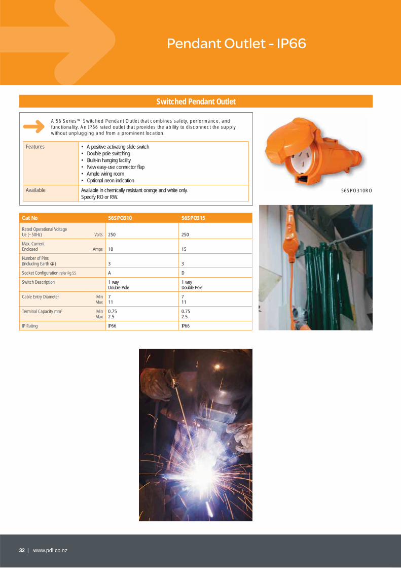
Switched Pendant Outlet
A 56 Series™ Switched Pendant Outlet that combines safety, performance, and functionality. An IP66 rated outlet that provides the ability to disconnect the supply without unplugging and from a prominent location.
Features • A positive activating slide switch• Double pole switching• Built-in hanging facility• New easy-use connector fl ap• Ample wiring room• Optional neon indication
Available Available in chemically resistant orange and white only. Specify RO or RW.
Cat No 56SPO310 56SPO315
Rated Operational Voltage Ue (~50Hz) Volts 250 250
Max. Current Enclosed Amps 10 15
Number of Pins (Including Earth ) 3 3
Socket Confi guration refer Pg 55 A D
Switch Description 1 way Double Pole
1 way Double Pole
Cable Entry Diameter MinMax
711
711
Terminal Capacity mm2 MinMax
0.752.5
0.752.5
IP Rating IP66 IP66
56SPO310RO
173
89.5 48.5
89.5
77
www.pdl.co.nz | 33
Dimensional Drawings
Cord Connectors - IP66
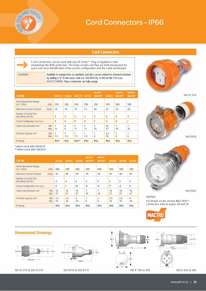
Cord Connectors
Cord Connectors can be used with any 56 Series™ Plug or Appliance Inlet maintaining the IP66 protection. The body section and fl ap are both transparent for quick and easy identifi cation of the socket confi guration and the cable termination.
Available Available in orange/clear as standard, and also can be ordered in chemical resistant by adding a “V” to the stock code (i.e. 56CRV310), or RO for the CSCs (i.e. 56CSC310RO). These connectors are fully orange.
Cat No 56CSC310 56CR310 56CSC315 56CR315
56CR320
MACTRO™ 56CR332
56CR416
MACTRO™
56CR420
MACTRO™
Rated Operational Voltage Ue (~50Hz) Volts 250 250 250 250 250 250 500 500
Maximum Current Enclosed Amps 10 10 15 15 20 32 16 20
Number of Socket Pins (Including Earth ) 3 3 3 3 3 3 4 4
Socket Confi guration refer Pg 55 A A D D F G H J
Cable Entry Diameter mm MinMax
711
69
711
711
716
1027
716
716
Terminal Capacity mm2 MinMax
11.5
11.5
11.5
11.5
16
2.516
16
16
IP Rating IP66* IP66 IP66** IP66 IP66 IP66 IP66 IP66
Cat No 56CR432 56CR440 56CR450
56CR516
MACTRO™
56CR520
MACTRO™ 56CR532 56CR540 56CR550
Rated Operational Voltage Ue (~50Hz) Volts 500 500 500 500 500 500 500 500
Maximum Current Enclosed Amps 32 40 50 16 20 32 40 50
Number of Socket Pins (Including Earth ) 4 4 4 5 5 5 5 5
Socket Confi guration refer Pg 55 K L M N O P Q R
Cable Entry Diameter mm MinMax
1027
1027
1027
716
716
1027
1027
1027
Terminal Capacity mm2 MinMax
2.516
2.516
416
16
16
2.516
2.516
416
IP Rating IP66 IP66 IP66 IP66 IP66 IP66 IP66 IP66
56CR43256CR
56CSC310
56CR42056CR420
85mm
120mm
55.2mm 12.1mm 31mm55.2mm
105.1mm
65mm12.1mm 31mm
96mm
186mm120mm
69mm58mm
77mm
* when used with 56AI310 ** when used with 56AI315
56CSC310 to 56CSC315 56CR310 to 56CR315 56CR 16A to 20A 56CR 32A to 50A
NOTES:
For details on the all new MACTRO™ connectors refer to pages 28 and 29
34 | www.pdl.co.nz
Dimensional Drawings
DIN Mounting MCB/RCD Covers - IP66
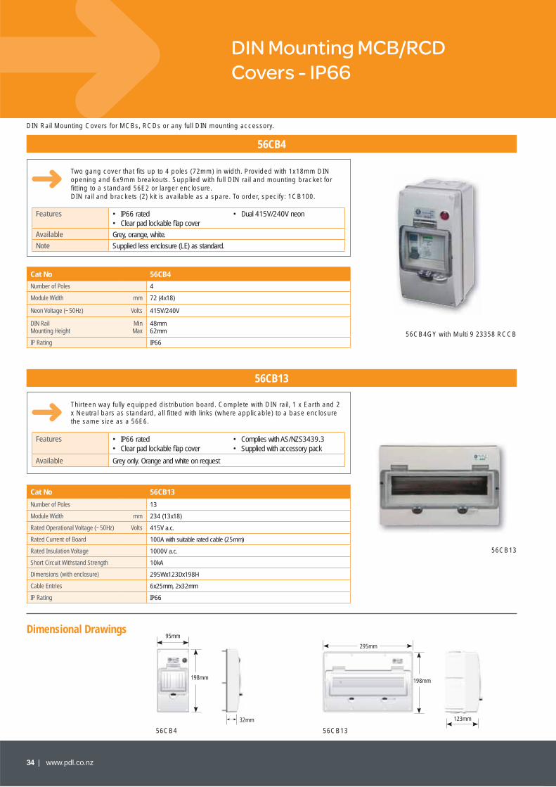
56CB4
56CB13
Two gang cover that fi ts up to 4 poles (72mm) in width. Provided with 1x18mm DIN opening and 6x9mm breakouts. Supplied with full DIN rail and mounting bracket for fi tting to a standard 56E2 or larger enclosure.DIN rail and brackets (2) kit is available as a spare. To order, specify: 1CB100.
Thirteen way fully equipped distribution board. Complete with DIN rail, 1 x Earth and 2 x Neutral bars as standard, all fi tted with links (where applicable) to a base enclosure the same size as a 56E6.
Features • IP66 rated • Dual 415V/240V neon• Clear pad lockable fl ap cover
Available Grey, orange, white.
Note Supplied less enclosure (LE) as standard.
Features • IP66 rated • Complies with AS/NZS3439.3• Clear pad lockable fl ap cover • Supplied with accessory pack
Available Grey only. Orange and white on request
Cat No 56CB4
Number of Poles 4
Module Width mm 72 (4x18)
Neon Voltage (~50Hz) Volts 415V/240V
DIN RailMounting Height
MinMax
48mm62mm
IP Rating IP66
Cat No 56CB13
Number of Poles 13
Module Width mm 234 (13x18)
Rated Operational Voltage (~50Hz) Volts 415V a.c.
Rated Current of Board 100A with suitable rated cable (25mm)
Rated Insulation Voltage 1000V a.c.
Short Circuit Withstand Strength 10kA
Dimensions (with enclosure) 295Wx123Dx198H
Cable Entries 6x25mm, 2x32mm
IP Rating IP66
DIN Rail Mounting Covers for MCBs, RCDs or any full DIN mounting accessory.
56CB4GY with Multi 9 23358 RCCB
56CB13
95mm
198mm
32mm
295mm
198mm
123mm
56CB4 56CB13
www.pdl.co.nz | 35
Dimensional Drawings
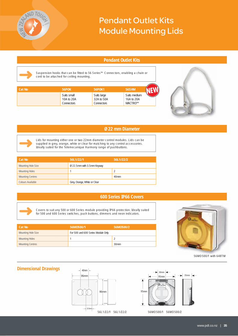
Pendant Outlet KitsModule Mounting Lids
Cat No 56POK 56POK1 56SHM
Suits small10A to 20AConnectors
Suits large32A to 50AConnectors
Suits medium16A to 20AMACTRO™
95mm
30mm
95mm
35mm
56L1/22/1 56L1/22/2 56MO500/1 56MO500/2
Pendant Outlet Kits
Ø 22 mm Diameter
600 Series IP66 Covers
Suspension hooks that can be fi tted to 56 Series™ Connectors, enabling a chain or cord to be attached for ceiling mounting.
95mm
95mm
22.5mm
40mm
Lids for mounting either one or two 22mm diameter control modules. Lids can be supplied in grey, orange, white or clear for matching to any control accessories. Ideally suited for the Telemecanique Harmony range of pushbuttons.
Covers to suit any 500 or 600 Series module providing IP66 protection. Ideally suited for 500 and 600 Series switches, push buttons, dimmers and neon indicators.
Cat No 56L1/22/1 56L1/22/2
Mounting Hole Size Ø 22.5mm with 3.5mm Keyway
Mounting Holes 1 2
Mounting Centres 40mm
Colours Available Grey, Orange, White or Clear
Cat No 56MO500/1 56MO500/2
Mounting Hole Size For 500 and 600 Series Module Only
Mounting Holes 1 2
Mounting Centres 30mm
56MO500/1 with 648TM

36 | www.pdl.co.nz
Dimensional Drawings
Enclosures
Enclosures
Cat No56E1S 56E1 56E1/25/25 56E2S 56E2 56E2
Food Industry56E2/25/25 56E2/40
Module Size1 Shallow 1 1
2 Shallow 2 2 2 2
Module Confi guration 1x1 1x1 1x1 2x1 2x1 2x1 2x1 2x1
DimensionsLengthWidthDepth
10210238
10210263
10210263
19810238
19810263
19810263
19810263
19810263
Conduit EntriesMetric mm* 25
3240
2––––––
11—
21—
2—–—–
11–––
2—–—–
21—–
––2
Conduit ReducersSupplied 25/20
32/251–
11
2–
1–
11
2–
21
––
Rear Entry Cut-Outs
1x25-20 1x32-25 1x32-25 2x25-20 1x321x25
1x321x25
1x25-201x32-25
1x25-201x32-25
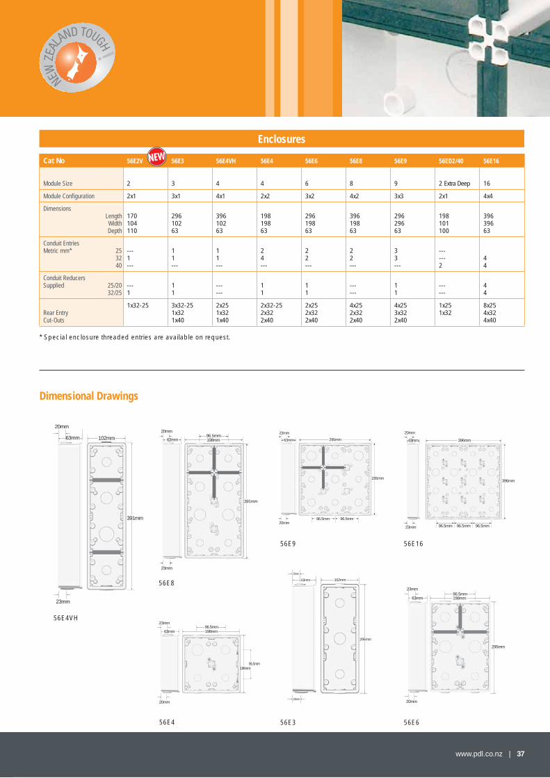
56 Series™ enclosures are in three types: shallow, in single and 2 gang sizes, suitable for mounting blank lids, single phase switches, single phase sockets and sunset switches; standard 63mm deep enclosures, which range in size from single gang to 16 gang; and an extra deep 100mm in 2 gang size for mounting large amperage products. They are moulded in impact resistant PVC.
All multigang enclosures are supplied complete with a selection of bridges to provide a sealing base between individual modules and dividers for separating incompatible circuits. Enclosures are supplied with a range of conduit entries according to the chart.
* Special enclosure threaded entries are available on request.Specify grey (GY), orange (RO), or white (RW).
56E1/25/25RW
56E8GY including dividers
56E2V
102mm
198mm
40mm63mm
23mm
20mm
102mm
102mm
63mm
20mm
23mm102mm
102mm
35mm
20mm
102mm
198mm
63mm
23mm
20mm
102mm
197mm
20mm
38mm
63mm
20mm
23mm102mm
102mm
40mm
56E1
56E2
56E1S
56E2/25/25
56E1/25/25
56E2S
38mm
www.pdl.co.nz | 37
Dimensional Drawings
Enclosures
Cat No 56E2V 56E3 56E4VH 56E4 56E6 56E8 56E9 56ED2/40 56E16
Module Size 2 3 4 4 6 8 9 2 Extra Deep 16
Module Confi guration 2x1 3x1 4x1 2x2 3x2 4x2 3x3 2x1 4x4
DimensionsLengthWidthDepth
170104110
29610263
39610263
19819863
29619863
39619863
29629663
198101100
39639663
Conduit EntriesMetric mm* 25
3240
---1---
11---
11---
24---
22---
22---
33---
------2
44
Conduit ReducersSupplied 25/20
32/25---1
11
------
11
11
------
11
------
44
Rear Entry Cut-Outs
1x32-25 3x32-251x321x40
2x251x321x40
2x32-252x322x40
2x252x322x40
4x252x322x40
4x253x322x40
1x251x32
8x254x324x40
396mm
396mm
96.5mm96.5mm96.5mm23mm
20mm
63mm
198mm
198mm
20mm
23mm
63mm96.5mm
96.5mm
295mm
20mm
23mm
63mm 198mm96.5mm
391mm
23mm
198mm96.5mm
20mm
63mm
295mm
295mm
96.5mm96.5mm20mm
23mm
63mm
102mm
295mm
63mm
23mm
20mm
102mm
391mm
63mm
20mm
23mm
* Special enclosure threaded entries are available on request.
56E4
56E4VH
56E8
56E9
56E3
56E16
56E6
38 | www.pdl.co.nz
Dimensional Drawings
Lids
Lids
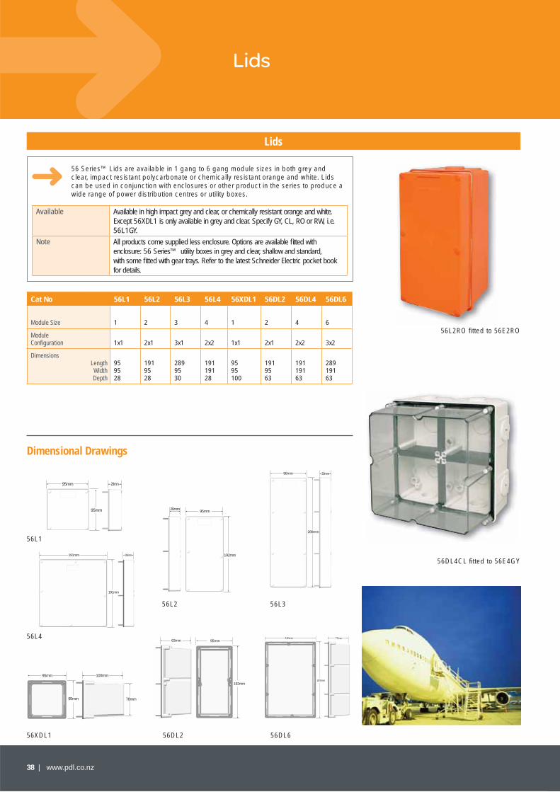
56 Series™ Lids are available in 1 gang to 6 gang module sizes in both grey and clear, impact resistant polycarbonate or chemically resistant orange and white. Lids can be used in conjunction with enclosures or other product in the series to produce a wide range of power distribution centres or utility boxes.
Available Available in high impact grey and clear, or chemically resistant orange and white. Except 56XDL1 is only available in grey and clear. Specify GY, CL, RO or RW, i.e. 56L1GY.
Note All products come supplied less enclosure. Options are available fi tted with enclosure: 56 Series™ utility boxes in grey and clear, shallow and standard, with some fi tted with gear trays. Refer to the latest Schneider Electric pocket book for details.
Cat No 56L1 56L2 56L3 56L4 56XDL1 56DL2 56DL4 56DL6
Module Size 1 2 3 4 1 2 4 6
Module Confi guration 1x1 2x1 3x1 2x2 1x1 2x1 2x2 3x2
DimensionsLengthWidthDepth
959528
1919528
2899530
19119128
9595100
1919563
19119163
28919163
56L2RO fi tted to 56E2RO
56DL4CL fi tted to 56E4GY
95mm
95mm
28mm
28mm
192mm
95mm
96mm
289mm
30mm
95mm
95mm 78mm
100mm
63mm
192mm
95mm
191mm
191mm 28mm
287mm
190mm 77mm
56L1
56L4
56XDL1 56DL2 56DL6
56L2 56L3
www.pdl.co.nz | 39
Dimensional Drawings
Pendant EnclosuresFlush Surrounds
Pendant Enclosures
Flush Surrounds
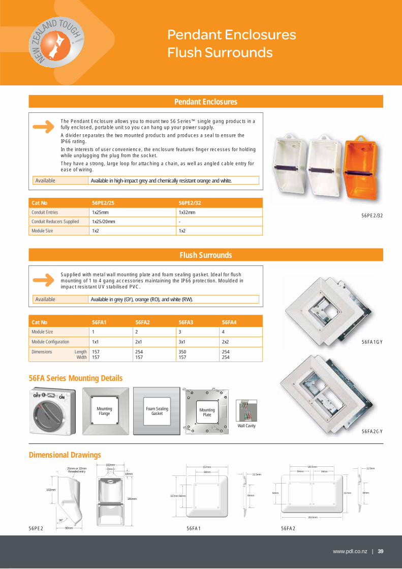
The Pendant Enclosure allows you to mount two 56 Series™ single gang products in a fully enclosed, portable unit so you can hang up your power supply.
A divider separates the two mounted products and produces a seal to ensure the IP66 rating.
In the interests of user convenience, the enclosure features fi nger recesses for holding while unplugging the plug from the socket.
They have a strong, large loop for attaching a chain, as well as angled cable entry for ease of wiring.
Supplied with metal wall mounting plate and foam sealing gasket. Ideal for fl ush mounting of 1 to 4 gang accessories maintaining the IP66 protection. Moulded in impact resistant UV stabilised PVC.
Available Available in high-impact grey and chemically resistant orange and white.
Available Available in grey (GY), orange (RO), and white (RW).
Cat No 56PE2/25 56PE2/32
Conduit Entries 1x25mm 1x32mm
Conduit Reducers Supplied 1x25/20mm -
Module Size 1x2 1x2
Cat No 56FA1 56FA2 56FA3 56FA4
Module Size 1 2 3 4
Module Confi guration 1x1 2x1 3x1 2x2
Dimensions LengthWidth
157157
254157
350157
254254
56PE2/32
56FA2GY
56FA1GY
102mm18mm
180mm
18mm
90mm
30°
25mm or 32mmthreaded entry
102mm
56FA1G
56FA2G
56PE2 56FA1 56FA2
11.5mm
84mm
157mm
84mm
84mm157mm
11.5mm
84mm
180.5mm
84mm84mm
84mm
253.5mm
157mm
56FA Series Mounting Details
MountingFlange
Foam Sealing Gasket
Mounting Plate
Wall Cavity
40 | www.pdl.co.nz
Accessories
Plugs and Connectors MACTRO™
Mounting Feet
Socket Covers Enclosures
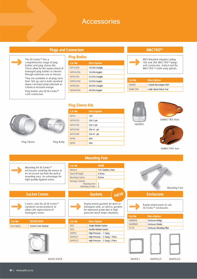
The 56 SeriesTM has a comprehensive range of plug bodies and plug sleeve kits. These allow for the replacement of damaged plug bodies or sleeves through extensive use or misuse.
They are available in all plug sizes from 16A up and in both standard impact resistant polycarbonate or chemical resistant orange.
Plug bodies also fi t 56 Series™ cord connectors.
M25 threaded adaptor suiting 16A and 20A MACTROTM plugs and connectors. Unlock tool for MACTROTM cable entry glands.
Mounting for 56 Series™ enclosures enabling the boxes to be recessed out from the wall or mounting area. An advantage for high quality hygiene areas.
Covers cater for all 56 Series™ standard socket products to allow safe replacement of damaged covers.
Replacement parts to suit 56 SeriesTM enclosures.
Cat No Description
56P16/20A 16/20A Straight
56PA16/20A 16/20A Angled
56P32/35A 32/35A Straight
56PA32/35A 32/35A Angled
56P40/50A 40/50A Straight
56PA40/50A 40/50A Angled
Cat No Description
56AM25 Conduit Nut Adaptor M25
56MACTRO Cable Gland Unlock Tool
Cat No 56SOCOVER
Description Socket Cover General
Cat No Description
56BRIDGE Enclosure Bridge
56DIVIDER Enclosure Divider
3S130 Enclosure Mounting Pillar
Cat No 56MF
Material 316 Stainless Steel
Stand off height 9.0mm
Mounting Centres 82mm
Package ContentsMounting Feet
Mounting Screws24
Cat No Description
56P16 16A
56P20/250 20A 3 pin
56P32/250 32A 3 pin
56P20/500 20A 4+ pin
56P32/500 32A 4+ pin
56P40 40A
56P50 50A
Plug Bodies
Plug Sleeve Kits
Plug BodyPlug Sleeve
56MACTRO front
56MACTRO rear
56AM25
Mounting Feet
Gaskets
Cat No Description
56G1 Single Module Gasket
56G2 Double Module Gasket
56HPG1 High Pressure – 1 Gang
56HPG2/1 High Pressure – 2 Gang, 1 Piece
56HPG2/2 High Pressure – 2 Gang, 2 Piece
Replacement gaskets for worn or damaged units, as well as gaskets for improved protection in high pressure wash down situations.
56SOCOVER 56HPG1 56HPG2/1 56HPG2/2
NEW
www.pdl.co.nz | 41
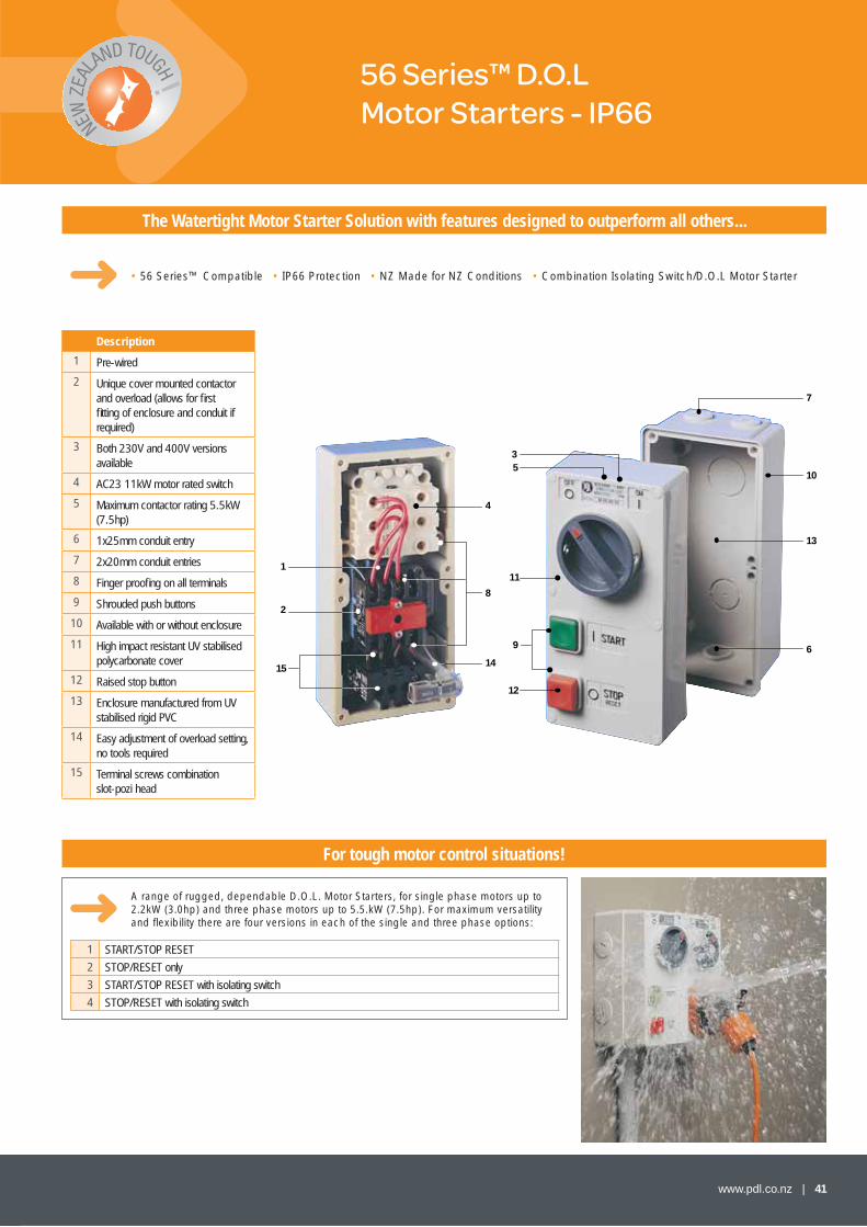
56 Series™ D.O.L Motor Starters - IP66
The Watertight Motor Starter Solution with features designed to outperform all others...
A range of rugged, dependable D.O.L. Motor Starters, for single phase motors up to 2.2kW (3.0hp) and three phase motors up to 5.5.kW (7.5hp). For maximum versatility and fl exibility there are four versions in each of the single and three phase options:
• 56 Series™ Compatible • IP66 Protection • NZ Made for NZ Conditions • Combination Isolating Switch/D.O.L Motor Starter
Description
1 Pre-wired
2 Unique cover mounted contactor and overload (allows for fi rst fi tting of enclosure and conduit if required)
3 Both 230V and 400V versions available
4 AC23 11kW motor rated switch
5 Maximum contactor rating 5.5kW (7.5hp)
6 1x25mm conduit entry
7 2x20mm conduit entries
8 Finger proofi ng on all terminals
9 Shrouded push buttons
10 Available with or without enclosure
11 High impact resistant UV stabilised polycarbonate cover
12 Raised stop button
13 Enclosure manufactured from UV stabilised rigid PVC
14 Easy adjustment of overload setting, no tools required
15 Terminal screws combination slot-pozi head
35
11
9
12
6
13
10
7
1
2
15
8
14
4
For tough motor control situations!
1 START/STOP RESET
2 STOP/RESET only
3 START/STOP RESET with isolating switch
4 STOP/RESET with isolating switch
42 | www.pdl.co.nz
Products in the Motor Starter Range - IP66
116mm20mm
105mm
63mm17.5mm
102mm
96mm
ø25mmconduit entry (x1)
40mm
ø20mm conduitentry (x2)
198m
m
192m
m
3mm
102mm
96mm
ø20mm conduitentry (x2)
ø25mmconduit entry (x1)
198m
m
192m
m
3mm
40mm
20mm
123mm
105mm
63mm17.5mm
116mm
Dimensional Drawings
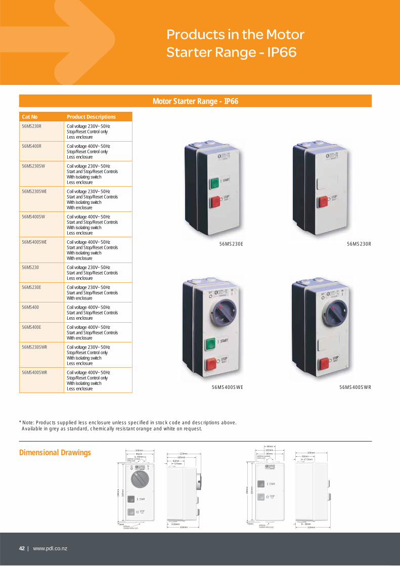
Motor Starter Range - IP66
Cat No Product Descriptions
56MS230R Coil voltage 230V~50Hz Stop/Reset Control only Less enclosure
56MS400R Coil voltage 400V~50Hz Stop/Reset Control only Less enclosure
56MS230SW Coil voltage 230V~50Hz Start and Stop/Reset Controls With isolating switch Less enclosure
56MS230SWE Coil voltage 230V~50Hz Start and Stop/Reset Controls With isolating switch With enclosure
56MS400SW Coil voltage 400V~50Hz Start and Stop/Reset Controls With isolating switch Less enclosure
56MS400SWE Coil voltage 400V~50Hz Start and Stop/Reset Controls With isolating switch With enclosure
56MS230 Coil voltage 230V~50Hz Start and Stop/Reset Controls Less enclosure
56MS230E Coil voltage 230V~50Hz Start and Stop/Reset Controls With enclosure
56MS400 Coil voltage 400V~50Hz Start and Stop/Reset Controls Less enclosure
56MS400E Coil voltage 400V~50Hz Start and Stop/Reset Controls With enclosure
56MS230SWR Coil voltage 230V~50HzStop/Reset Control only With isolating switch Less enclosure
56MS400SWR Coil voltage 400V~50Hz Stop/Reset Control only With isolating switch Less enclosure
56MS230E
56MS400SWE
56MS230R
56MS400SWR
* Note: Products supplied less enclosure unless specifi ed in stock code and descriptions above. Available in grey as standard, chemically resistant orange and white on request.

www.pdl.co.nz | 43
1 3 5 1321
2 4 6 14C
2 4 6
U V W
98 96
95
START
STOPRESET
MOTOR LOAD
A1
A2400
L1 L2 L3MAINS SUPPLY E
Connection Diagrams
Starter and Overload
L1 L2 L3
1 3 5 132
E
MAINS SUPPLY
1
2 4 6 14C
2 4 6
U V W
98 96
95
ONOFF
START
STOPRESET
MOTOR LOAD
A1
A2400
L1 L2 L3
1 3 5 132
E
MAINS SUPPLY
1
2 4 6 14C
2 4 6
U V W
98 96
95
ONOFF
START
STOPRESET
MOTOR LOAD
A1
A2230
Remove link between A1and 1 at terminal 1 oncontactor and connectto neutral.
Connect link wireattached to contactorterminal 3 to switch.
N
Remove link betweenA1 and 1 at terminal 1on contactor andconnect to neutral.
Remove link wire attachedto contactor terminal 3.
1 3 5 1321
2 4 6 14C
2 4 6
U V W
98 96
95
START
STOPRESET
MOTOR LOAD
A1
A2230
L1 L2 L3MAINS SUPPLY EN
1 3 5 1321
2 4 6 14C
2 4 6
N A
98 96
95
START
STOPRESET
MOTOR LOAD
A1
A2230
Connect link wireattached to contactorterminal 3 to terminal6 on overload.
N AEMAINS SUPPLY
REMOTE STOP/ST ART PUSH BUTTONS
REMOTE STOP PUSH BUTTONRemove linkbetween 14and 96 onstarter andconnect asshown.
STOP
14 96
14
96
START STOP
13
Technical Information
Typical connection diagrams for motor starter options, full instructions and connection diagrams are supplied with products.
GENERAL
Direct on Line Motor Starter
Maximum Rated Output
AC3 5.5kW 400V – Three PhaseAC3 2.2kW 230V – Single Phase
Maximum Thermal Current Enclosed
16A
IP66 Dust and Watertight
AS 1939:1990BS 5490:1985IEC 529 :1989
Finger proof terminals on contactor, overload and isolating switch to IP20
CONTACTOR
Type S12 10 Electromagnetic Contactor3 pole + N/O Auxiliary
Frequency 50Hz AC
Utilisation Category
AC3 7.5kW 400V – Three PhaseAC3 2.2kW 230V – Single Phase
Rated Insulation Voltage Ui
690V~
Rated Thermal Current Enclosed
16A
Coil Characteristics
Pull in 0.85 - 1.1 Uc (Control Circuit Voltage) Drop Out 0.4 - 0.6 Uc
Terminal Capacities
Stranded 0.5 - 2.5mm2
Solid 0.75 - 4mm2
OVERLOAD
Full Load Current Rating
0.40 - 16 Amps in 10 size ranges
Rated Insulation Voltage Ui: 660V AC
Single Phase ProtectedTemperature Compensated
From 0 - 35°C
Manual or Auto Reset
Manual Test Incorporated
Alarm Control N/O
AUXILIARY CONTACTS
Rated Insulating Voltage
500V AC
Rated Operational Current le
AC11 2A 500V
TERMINAL CAPACITIES
Main Stranded 0.5 - 2.5mm2 Solid 0.5 - 4mm2
Auxiliary Stranded 0.5 -2.5mm2 Solid 0.5 - 2.5mm2
START PUSH BUTTON SWICH
Rated Insulation Voltage Ui
500V AC
Rated Thermal Current 16A
Utilisation Category AC11 4A 250VAC11 2A 415V
ENCLOSURE
Rigid PVC – UV stabilised, impact resistant.Screwed Conduit Entries Back Entry Cut-Outs1 x Ø 25mm 1 x Ø 32mm2 x Ø 20mm 1 x Ø 25mm
MOTOR RATED ISOLATING SWITCH
Used with 56MS230SW, 56MS400SW, 56MS230SWR, 56MS400SWR 3 pole isolating. Motor rated toAC23 11kW 415V BS5419M110 20A 500V AS3133
3 Phase 3 Wire Supply – 56MS400SW
3 Phase 4 Wire Supply – 56MS230SW Remote Controls
MAINS SUPPLYN A
1 3 5 132
E
1
2 4 6 14C
2 4 6
N A
98 96
95
ONOFF
START
STOPRESET
MOTOR LOAD
A1
A2230
Connect link wire attachedto contactor terminal 3 toterminal 6 on overload.
Single Phase & Neutral Supply – 56MS230SW
3 Phase 3 Wire Supply – 56MS400
3 Phase 4 Wire Supply – 56MS230
Single Phase & Neutral Supply – 56MS230
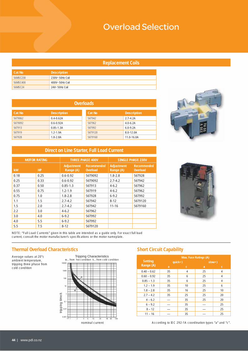
44 | www.pdl.co.nz
Overload Selection
Replacement Coils
Direct on Line Starter, Full Load Current
Overloads
Cat No Description
56MSC230 230V~50Hz Coil
56MSC400 400V~50Hz Coil
56MSC24 24V~50Hz Coil
MOTOR RATING THREE PHASE 400V SINGLE PHASE 230V
kW HPAdjustment Range (A)
Recommended Overload
Adjustment Range (A)
Recommended Overload
0.18 0.25 0.6-0.92 56T9092 1.8-2.8 56T928
0.25 0.33 0.6-0.92 56T9092 2.7-4.2 56T942
0.37 0.50 0.85-1.3 56T913 4-6.2 56T962
0.55 0.75 1.2-1.9 56T919 4-6.2 56T962
0.75 1.0 1.8-2.8 56T928 6-9.2 56T992
1.1 1.5 2.7-4.2 56T942 8-12 56T9120
1.5 2.0 2.7-4.2 56T942 11-16 56T9160
2.2 3.0 4-6.2 56T962
3.0 4.0 6-9.2 56T992
4.0 5.5 6-9.2 56T992
5.5 7.5 8-12 56T9120
Cat No Description Cat No Description
56T9062 0.4-0.62A 56T942 2.7-4.2A
56T9092 0.6-0.92A 56T962 4.0-6.2A
56T913 0.85-1.3A 56T992 6.0-9.2A
56T919 1.2-1.9A 56T9120 8.0-12.0A
56T928 1.8-2.8A 56T9160 11.0-16.0A
Average values at 20°c ambient temperature, tripping three phase from cold condition
Tripping Characteristicsw…from hot condition k…from cold condition
trip
pin
g ti
me/
s
10000
1000
100
10
1
0.1
0.01
0.0011 2 4 6 10 20 40 60 100
w
k
0.8
nominal current
NOTE: “Full Load Currents” given in this table are intended as a guide only. For exact full load current, consult the motor manufacturer’s specifi cations or the motor nameplate.
Setting Range (A)
Max. Fuse Ratings (A)
quick+) slow+)
a c a c
0.40 – 0.62 35 4 25 4
0.60 – 0.92 35 6 25 4
0.85 – 1.3 35 6 25 4
1.2 – 1.9 35 10 25 6
1.8 – 2.8 35 16 25 10
2.7 – 4.2 35 25 25 20
4 – 6.2 — 35 25 20
6 – 9.2 — 35 — 25
8 – 12 — 35 — 25
11 – 16 — 35 — 25
According to IEC 292-1A coordination types “a” and “c”.
Thermal Overload Characteristics Short Circuit Capability

www.pdl.co.nz | 45
International Standards and Approvals
Defi nition of Utilisation Categories
Technical Information
Technical Information
DIRECT ON LINE MOTORSTARTER
International Protection IP66 to AS 1939:1990 and BS 5490:1977.AS 1202 Pt 1:1981 AC Motorstarters Direct on LineBS 4941 Pt 1:1979 Direct on Line AC Starters IEC 947, switch operation and cover markingPatented Stop/Reset MechanismThe switched versions (56MS400SW and 56MS230SW) comply with New Zealand Electrical Wiring Regulation 108.Manufactured to ISO 9001
AC23A
Switching of motor loads or other highly inductive loads.Occasional:Making 10 times le (Rated operational current)Breaking 8 times le
AC3
Starting of squirrel cage motors, and switching off motors during running.Occasional:Making 10 times leBreaking 10 times le
AC11
Feed control of magnetic drives, contactors, valves and electromagnets.Occasional:Making 11 times leBreaking 11 times le
CONTACTOR
IEC 947EN 60947VDE 0660Manufactured to ISO 9001
OVERLOAD
IEC 292VDE 0660BS 587 and BS 5424Manufactured to ISO 9001

46 | www.pdl.co.nz
Technical Section
Chemical Resistance
Rating Conversion
Chemical Compatibility 56 Series Grey
56 Series Orange & White
56 Series Enclosures
AcidsHydrochloric Acid (10%) A A A
Sulphuric Acid (10%) A A A
Acetic Acid (10%) A A A
Nitric Acid (10%) B A A
BasesPotassium Hydroxide C A A
Sodium Hydroxide D B A
Ammonium Hydroxide D B B
Organic SolventsEthyl Alcohol A A A
Methyl Alcohol (Methanol) B A A
Isopropyl Alcohol A A A
Acetone D B D
Methylethylketone D D D
Ethyl Acetate D A N/T
Ethylene Glycol B A N/T
Methyl Benzene D B D
Xylene D C D
Automotive Related EnvironmentsMotor Oil C A N/T
Transmission Fluid D B N/T
Power Steering Fluid D B N/T
Brake Fluid D C N/T
Unleaded Petrol D B A
Diesel Fuel A A A
1 PHASE
kW hp 240VA
0.37 0.5 3.6
0.55 0.75 4.8
0.75 1 6.1
1.1 1.5 8.8
1.5 2 11.7
1.8 2.5 14.4
2.2 3 17.1
3 4 22.2
4 5 27.1
4.4 6 31.8
5.2 7 36.5
5.5 7.5 38.7
6 8 40.8
7 9 45.4
7.5 10 50
3 PHASE
kW hp 415VA
500VA
0.37 0.5 - 1
0.55 0.75 - 1.21
0.75 1 1.8 1.5
1.1 1.5 2.6 2.2
1.5 2 3.5 2.9
2.2 3 5 3.8
3 4 6.5 5
3.7 5 7.5 5.9
4 5.5 8.4 6.5
5.5 7.5 11 9
7.5 10 15 12
9 12 17 13.9
10 13.5 - 15
11 15 21 18.4
15 20 28 23
18.5 25 35 28.5
22 30 40 33
25 35 47 39.4
30 40 55 45
33 45 60 50
Chemical Compatibility 56 Series Grey
56 Series Orange & White
PDL Enclosures
SaltsZinc Chloride (10%) B A BCalcium Chloride (10%) B A BSodium Chloride (5%) B A BOxidising AgentsSodium Hypochlorite (5%) A A A
Hydrogen Peroxide (30%) A A A
OthersMild Detergent B A A
Hot Water @ 60 degrees A A B
Mechanical and Thermal PropertiesOutdoor Use – Mechanical Properties A AOutdoor Use – Colour Properties B BIndoor Use A A ALightweight A A AHigh Rigidity B BImpact Resistance A B CUV Deterioration A B A
A – Excellent Compatible, no problems expected from the use of the chemical with this part.
B – Good Acceptable, minimal loss of chemical properties after prolonged exposure.
C – Fair Marginally compatible, extended use of the chemical may cause deterioration and cracking of the part.
D – Poor Incompatible. Do not recommend the use of the chemical with this part.
N/T Not Tested
This table is a guide only. Performance of product in a particular environment will be affected by a wide variety of factors, of which chemical compatibility is only one. End users should test for their particular environment.
RATINGS
These values are given as a guide only.They may vary depending on the type of motor and the manufacturer.

www.pdl.co.nz | 47
Switch Rating Information
IEC60947-3 Low Voltage Switchgear and controlgear – Switches, disconnectors, switch disconnectors and fuel-combination units. Several ratings are referred to in detail. Note that ratings in the format AC21A can be interpreted as follows:
• AC refers to AC supply. Alternative is DC.
• 21 refers to the utilisation of the rating. Alternatives include 15, 23, 3 and detail on each can be found below.
• A refers to “frequent operation”. No number is specifi ed for frequent operation, although the test programme tests at 30 second intervals. B is the alternative, covering infrequent operation, maybe one switching per day or month.
AS/NZS3133 Approval and test specifi cation – Air break switches. Three different ratings are referred to in detail:
• Resistive rating
• M Motor rating
• X Inductive or fl uorescent rating
Pure resistive loads include heating elements. Very few loads, if any, are 100% resistive and this test includes a moderate inductive component in recognition of this.
As above, this rating covers AC supply and frequent operation. AC23A is the best utilisation category for switching of the most common types of motors. Most other highly inductive loads typically involve motors of some type. Examples are heat pumps, compressors and air conditioners.
The AC23A rating of a 56SW350GY switch is 35 Amps (18.5 kW). This switch can be matched to a motor that has a full load current of up to 35 Amps.
Generally, these switches are used in conjunction with other motor control equipment such as motorstarters or soft starters and only have to operate during a fault or period of isolation.
= Disconnector (Isolating only)
Glossary
IEC60947-3 AC21ASwitching of resistive loads including a moderate overload
IEC60947-3 AC23ASwitching of motor or other highly inductive loads
IEC60947-3 International Device Classifi cations
An isolation device, under AS/NZS 3000:2000, section 2.8.3.2 must:
• Be capable of withstanding an impulse voltage likely to occur at the point of installation, or shall have an appropriate contact gap.
• Not be able to falsely indicate that the contacts are open.
= Switch Disconnector (Or Switch Isolator-Making, Breaking and Isolating)
IMPORTANT
The above information is an opinion only. All installers and equipment users should satisfy themselves as to the suitability of equipment for each particular application. No liability will be accepted for reliance on this information.
48 | www.pdl.co.nz
Switch Rating Information
AC3 has no A or B classifi cation for frequency of operation and all ratings are for frequent operation. AC3 provides ratings directly applicable to the direct starting and switching off of motors during operation and as such is one of the harshest switch ratings available for motors.
The AC3 rating of an 56SW350GY switch is 28 Amps (15kW). This switch can be used to start or stop a motor that has a full load current of up to 28 Amps.
AC3 is the rating best suited for control equipment being turned on or off directly under load. Examples include conveyors, lathes and process equipment. With a frequent operation classifi cation, these switches may be operated many times per hour.
This rating covers the switch control of electromagnetic loads, including control devices such as relays, contactors, and valves.
As for AC21A except covers DC applications.
As for DC21A except covers mixed resistive and inductive loads. For example shunt motors.
Like AC3, AC4 has no A or B classifi cation for frequency of operation and all ratings are for frequent operation.
AC4 provides ratings in addition to AC3 relating to motors which are rapidly reversed while running (plugging), or operated repeatedly to obtain small movements of a mechanism (inching) and as such is one of the harshest switch ratings available for motors.
The AC4 rating is applied only to the K and N control switches. The 56SW320CO has an AC4 rating of 1.5kW. This switch can be used to make or break a load of 1.5kW.
IEC60947-3 AC3Switching of squirrel-cage motors
IEC60947-3 AC15Control of electromagnetic loads
IEC60947-3 DC21ASwitching of DC resistive loads
IEC60947-3 DC22ASwitching of DC mixd resistive and inductive loads
This is the recommended maximum current the switch can withstand under fault conditions without failing or showing signs of damage and is the switch equivalent of a 4.5kA or 6kA rating assigned to an MCB. Values are expressed as kA.
A 56SW350GY switch has a 1.5kA rating so it can carry a 1500 Amp load for 1 second without damage.
IEC60947-3 requires performance of at least 12x rated current for 1 second. 56 Series™ switches offer performance levels much higher than this.
IEC60947-3 Rated short time withstand current (lcw/kA)
IEC60947-3 AC4Switching of squirrel-cage motors, starting, plugging and inching
IMPORTANT
The above information is an opinion only. All installers and equipment users should satisfy themselves as to the suitability of equipment for each particular application. No liability will be accepted for reliance on this information.
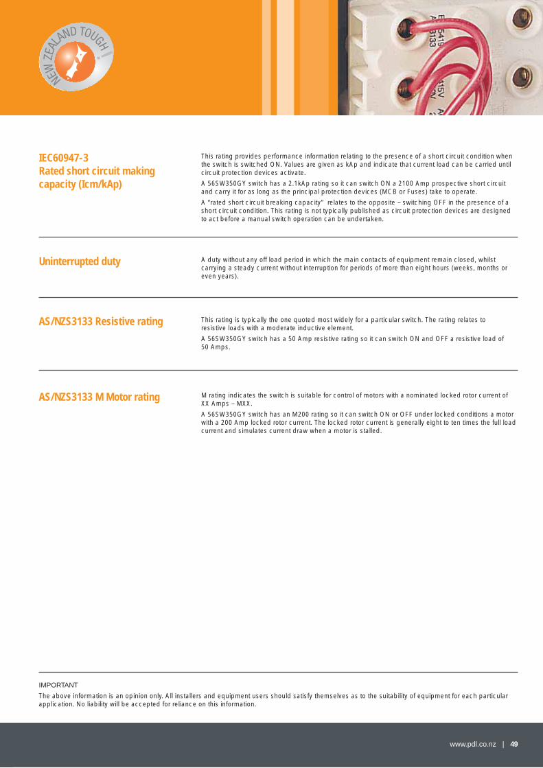
www.pdl.co.nz | 49
This rating provides performance information relating to the presence of a short circuit condition when the switch is switched ON. Values are given as kAp and indicate that current load can be carried until circuit protection devices activate.
A 56SW350GY switch has a 2.1kAp rating so it can switch ON a 2100 Amp prospective short circuit and carry it for as long as the principal protection devices (MCB or Fuses) take to operate.
A “rated short circuit breaking capacity” relates to the opposite – switching OFF in the presence of a short circuit condition. This rating is not typically published as circuit protection devices are designed to act before a manual switch operation can be undertaken.
This rating is typically the one quoted most widely for a particular switch. The rating relates to resistive loads with a moderate inductive element.
A 56SW350GY switch has a 50 Amp resistive rating so it can switch ON and OFF a resistive load of 50 Amps.
M rating indicates the switch is suitable for control of motors with a nominated locked rotor current of XX Amps – MXX.
A 56SW350GY switch has an M200 rating so it can switch ON or OFF under locked conditions a motor with a 200 Amp locked rotor current. The locked rotor current is generally eight to ten times the full load current and simulates current draw when a motor is stalled.
A duty without any off load period in which the main contacts of equipment remain closed, whilst carrying a steady current without interruption for periods of more than eight hours (weeks, months or even years).
IEC60947-3 Rated short circuit making capacity (Icm/kAp)
AS/NZS3133 Resistive rating
AS/NZS3133 M Motor rating
Uninterrupted duty
IMPORTANT
The above information is an opinion only. All installers and equipment users should satisfy themselves as to the suitability of equipment for each particular application. No liability will be accepted for reliance on this information.
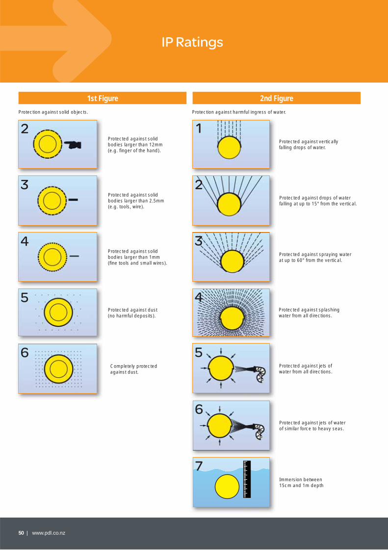
50 | www.pdl.co.nz
IP Ratings
Protection against solid objects. Protection against harmful ingress of water.
1st Figure 2nd Figure
Protected against vertically falling drops of water.
Protected against solid bodies larger than 12mm(e.g. fi nger of the hand).
2 1
Protected against solid bodies larger than 2.5mm(e.g. tools, wire).
3Protected against drops of water falling at up to 15° from the vertical.
2
Protected against solid bodies larger than 1mm (fi ne tools and small wires).
4Protected against spraying water at up to 60° from the vertical.
3
Protected against dust (no harmful deposits).
5Protected against splashing water from all directions.
4
Completely protected against dust.
6Protected against jets of water from all directions.
5
Protected against jets of water of similar force to heavy seas.
6
Immersion between15cm and 1m depth
7
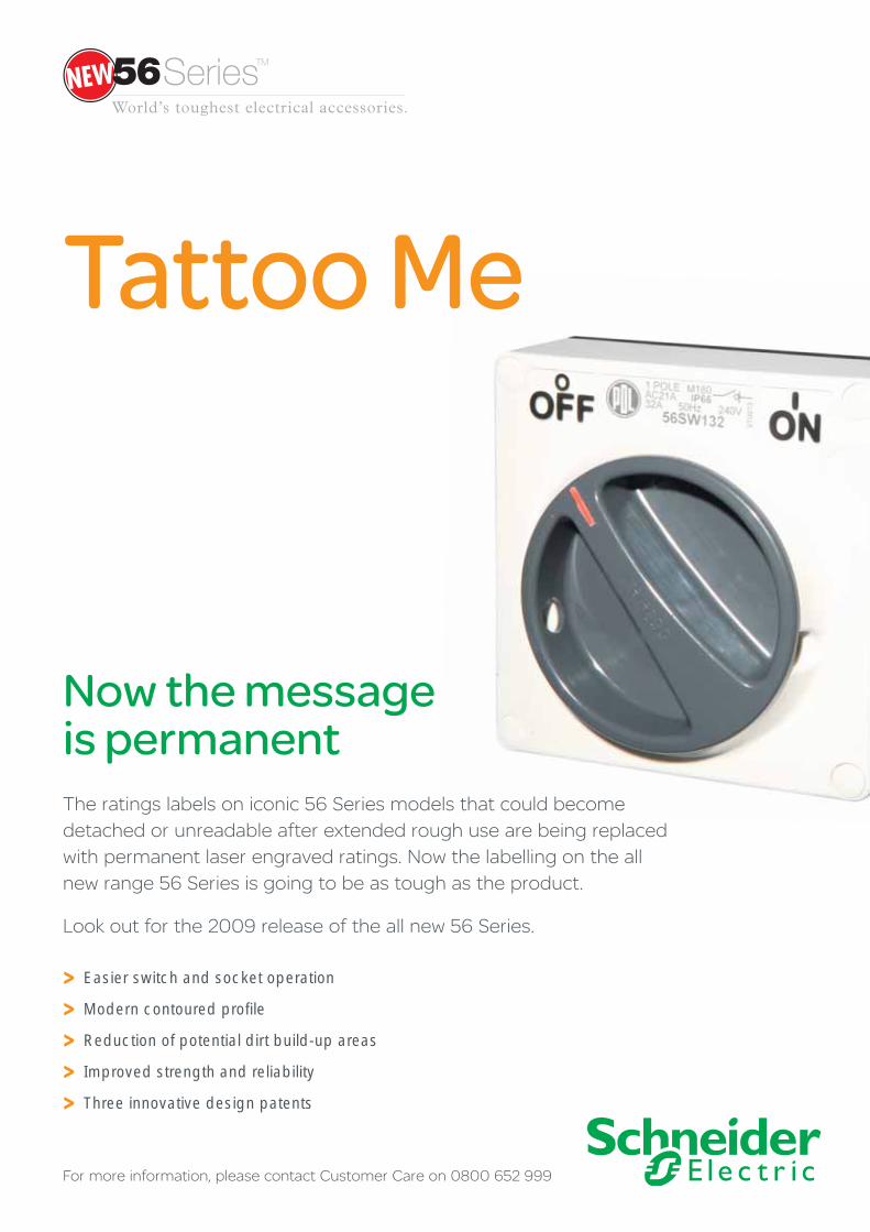
> Easier switch and socket operation
> Modern contoured profi le
> Reduction of potential dirt build-up areas
> Improved strength and reliability
> Three innovative design patents
The ratings labels on iconic 56 Series models that could become detached or unreadable after extended rough use are being replaced with permanent laser engraved ratings. Now the labelling on the all new range 56 Series is going to be as tough as the product.
Look out for the 2009 release of the all new 56 Series.
Now the message is permanent
Tattoo Me
For more information, please contact Customer Care on 0800 652 999

52 | www.pdl.co.nz
Index
Cat No Page
1CB100 34
3S130 40
56AI310 27
56AI315 27
56AI320 27
56AI332 27
56AI416 27
56AI420 27
56AI432 27
56AI440 27
56AI450 27
56AI516 27
56AI520 27
56AI532 27
56AI540 27
56AI550 27
56AM25 40
56BRIDGE 40
56C310EL2P 26
56C310RCD30 25
56C316RCD30 25
56C320RCD30 25
56CB13 34
56CB4 34
56CR310 33
56CR315 33
56CR320 33
56CR332 33
56CR416 33
56CR420 33
56CR432 33
56CR440 33
56CR450 33
56CR516 33
56CR520 33
56CR532 33
56CR540 33
56CR550 33
56CSC310 33
56CSC315 33
56CV310 21
56CV315 21
56CV316/240 22
56CV320 22
Cat No Page
56CV332 22
56CV416 23
56CV420 23
56CV432 23
56CV440 23
56CV450 23
56CV516 24
56CV520 24
56CV532 24
56CV540 24
56CV550 24
56CV616 24
56CV716 24
56CV720 24
56DIVIDER 40
56DL2 38
56DL4 38
56DL6 38
56E1 36
56E1/25/25 36
56E16 37
56E1S 36
56E2 36
56E2/25/25 36
56E2/40 36
56E2FOOD 36
56E2S 36
56E2V 17, 37
56E3 37
56E4 37
56E4VH 37
56E6 37
56E8 37
56E9 37
56ED2/40 37
56FA1 39
56FA2 39
56FA3 39
56FA4 39
56G1 40
56G2 40
56HPG1 40
56HPG2/1 40
56HPG2/2 40
56LEDK1 11
Cat No Page
56LEDK3 11
56L1 38
56L1/22/1 35
56L1/22/2 35
56L2 38
56L3 38
56L4 38
56MACTRO 40
56MF 40
56MO500/1 35
56MO500/2 35
56MS230 42
56MS230E 42
56MS230R 42
56MS230SWE 42
56MS230SWR 42
56MS400 42
56MS400E 42
56MS400R 42
56MS400SW 42
56MS400SWE 42
56MS400SWR 42
56MSC230 44
56MSC24 44
56MSC400 44
56P16 40
56P16/20A 40
56P20/250 40
56P20/500 40
56P310 30
56P310R 30
56P315 30
56P32/250 40
56P32/35A 40
56P32/500 40
56P320 30
56P320F 30
56P332 30
56P40 40
56P40/50A 40
56P416 31
56P416K 31
56P420 31
56P432 31
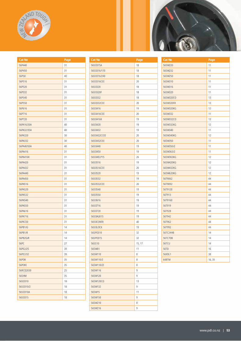
www.pdl.co.nz | 53
Cat No Page
56P440 31
56P450 31
56P50 40
56P516 31
56P520 31
56P532 31
56P540 31
56P550 31
56P616 31
56P716 31
56P720 31
56PA16/20A 40
56PA32/35A 40
56PA320 30
56PA332 30
56PA40/50A 40
56PA416 31
56PA416K 31
56PA420 31
56PA432 31
56PA440 31
56PA450 31
56PA516 31
56PA520 31
56PA532 31
56PA540 31
56PA550 31
56PA616 31
56PA716 31
56PA720 31
56PB1/G 14
56PB1/R 14
56PB2G/R 14
56PC 27
56PE2/25 39
56PE2/32 39
56POK 35
56POKI 35
56RCD2030 25
56SHM 35
56SO310 18
56SO310/2 18
56SO310A 18
56SO315 18
Cat No Page
56SO315A 18
56SO316/110 18
56SO316/240 18
56SO316CEE 20
56SO320 18
56SO320F 18
56SO332 18
56SO332CEE 20
56SO416 19
56SO416CEE 20
56SO416K 19
56SO420 19
56SO432 19
56SO432CCEE 20
56SO432CEE 20
56SO440 19
56SO450 19
56SO4ELP15 26
56SO516 19
56SO516CEE 20
56SO520 19
56SO532 19
56SO532CEE 20
56SO540 19
56SO550 19
56SO616 19
56SO716 19
56SO720 19
56SOAUX15 19
56SOCOVER 40
56SOLOCK 19
56SPO310 32
56SPO315 32
56SS10 15, 17
56SW01 11
56SW110 8
56SW110/2 8
56SW110/2I 8
56SW116 9
56SW120 9
56SW120CO 13
56SW132 9
56SW15 11
56SW150 9
56SW210 8
56SW216 9
Cat No Page
56SW220 11
56SW232 11
56SW250 11
56SW310 11
56SW316 11
56SW320 11
56SW320CO 13
56SW320FR 13
56SW320KG 12
56SW332 11
56SW332CO 13
56SW332KG 12
56SW340 11
56SW340KG 12
56SW350 11
56SW350/2 11
56SW363/2 11
56SW363KG 12
56SW420KG 12
56SW432KG 12
56SW620KG 12
56T9062 44
56T9092 44
56T9120 44
56T913 44
56T9160 44
56T919 44
56T928 44
56T942 44
56T962 44
56T992 44
56TC24HB 14
56TC7DB 14
56TCU 14
56TD 16
56XDL1 38
648TM 16, 35
54 | www.pdl.co.nz
Notes
PDL 56 Series™ Product Master Notes
1. 56AI310 suits 56CSC310 only; 56AI315 suits 56CSC315 only
2. 56SPO310 & 56SPO315 RO and RW
3. All CEE17 sockets are available in grey only
4. 56SO432CCEE & matching plug & connector specifi cally for international container equipment – earth pin position = 3H
5. 56SO416K and matching plugs with a special keyway for dedicated applications where standard products should not be used.
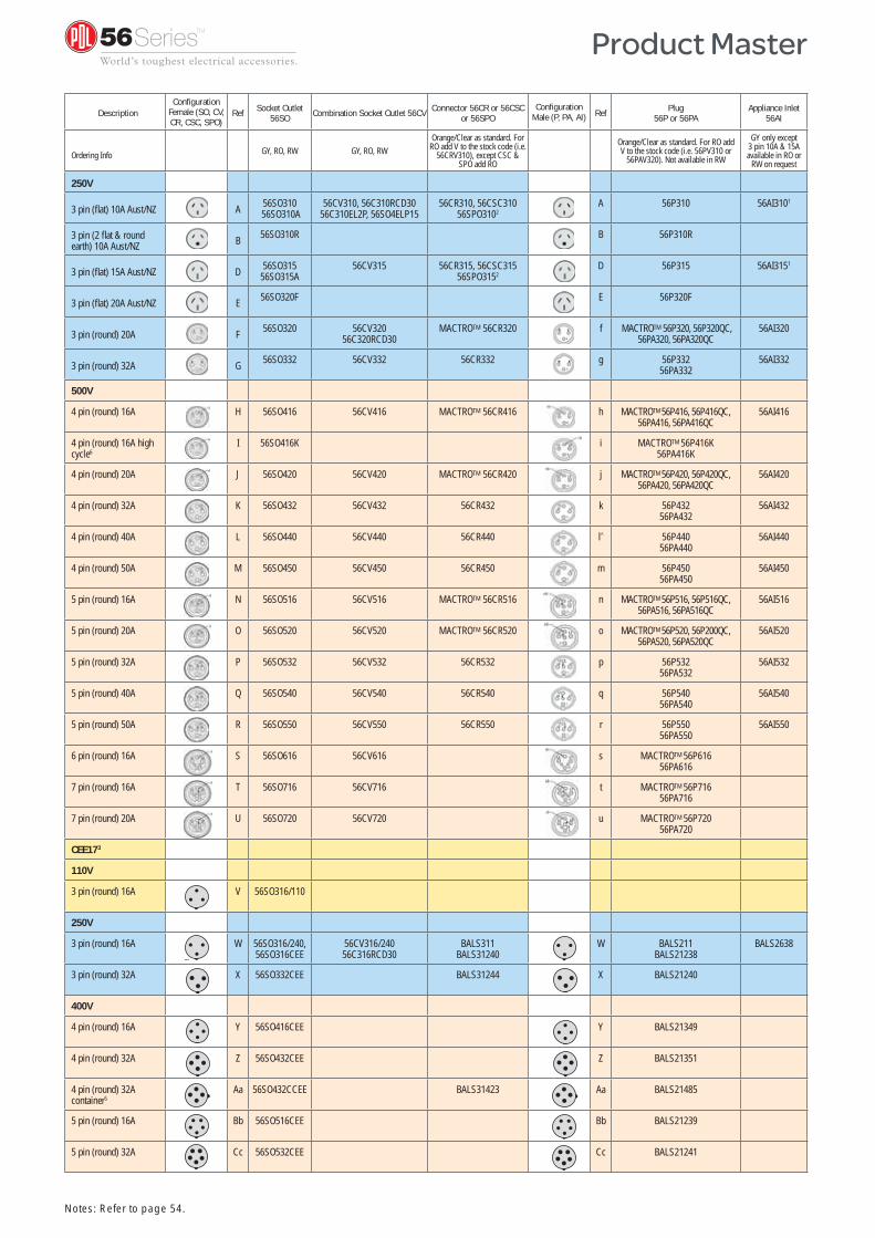
DescriptionConfi guration
Female (SO, CV, CR, CSC, SPO)
Ref Socket Outlet 56SO Combination Socket Outlet 56CV Connector 56CR or 56CSC
or 56SPOConfi guration
Male (P, PA, AI) Ref Plug 56P or 56PA
Appliance Inlet56AI
Ordering Info GY, RO, RW GY, RO, RWOrange/Clear as standard. For
RO add V to the stock code (i.e. 56CRV310), except CSC &
SPO add RO
Orange/Clear as standard. For RO add V to the stock code (i.e. 56PV310 or
56PAV320). Not available in RW
GY only except3 pin 10A & 15A available in RO or
RW on request
250V
3 pin (fl at) 10A Aust/NZ A 56SO310 56SO310A
56CV310, 56C310RCD3056C310EL2P, 56SO4ELP15
56CR310, 56CSC31056SPO3102
A 56P310 56AI3101
3 pin (2 fl at & round earth) 10A Aust/NZ B 56SO310R B 56P310R
3 pin (fl at) 15A Aust/NZ D 56SO31556SO315A
56CV315 56CR315, 56CSC31556SPO3152
D 56P315 56AI3151
3 pin (fl at) 20A Aust/NZ E 56SO320F E 56P320F
3 pin (round) 20A F 56SO320 56CV32056C320RCD30
MACTROTM 56CR320 f MACTROTM 56P320, 56P320QC, 56PA320, 56PA320QC
56AI320
3 pin (round) 32A G 56SO332 56CV332 56CR332 g 56P33256PA332
56AI332
500V
4 pin (round) 16A H 56SO416 56CV416 MACTROTM 56CR416 h MACTROTM 56P416, 56P416QC, 56PA416, 56PA416QC
56AI416
4 pin (round) 16A high cycle6
I 56SO416K i MACTROTM 56P416K56PA416K
4 pin (round) 20A J 56SO420 56CV420 MACTROTM 56CR420 j MACTROTM 56P420, 56P420QC, 56PA420, 56PA420QC
56AI420
4 pin (round) 32A K 56SO432 56CV432 56CR432 k 56P43256PA432
56AI432
4 pin (round) 40A L 56SO440 56CV440 56CR440 l^ 56P44056PA440
56AI440
4 pin (round) 50A M 56SO450 56CV450 56CR450 m 56P45056PA450
56AI450
5 pin (round) 16A N 56SO516 56CV516 MACTROTM 56CR516 n MACTROTM 56P516, 56P516QC, 56PA516, 56PA516QC
56AI516
5 pin (round) 20A O 56SO520 56CV520 MACTROTM 56CR520 o MACTROTM 56P520, 56P200QC, 56PA520, 56PA520QC
56AI520
5 pin (round) 32A P 56SO532 56CV532 56CR532 p 56P53256PA532
56AI532
5 pin (round) 40A Q 56SO540 56CV540 56CR540 q 56P54056PA540
56AI540
5 pin (round) 50A R 56SO550 56CV550 56CR550 r 56P55056PA550
56AI550
6 pin (round) 16A S 56SO616 56CV616 s MACTROTM 56P61656PA616
7 pin (round) 16A T 56SO716 56CV716 t MACTROTM 56P71656PA716
7 pin (round) 20A U 56SO720 56CV720 u MACTROTM 56P72056PA720
CEE173
110V
3 pin (round) 16A V 56SO316/110
250V
3 pin (round) 16A W 56SO316/240,56SO316CEE
56CV316/24056C316RCD30
BALS311BALS31240
W BALS211BALS21238
BALS2638
3 pin (round) 32A X 56SO332CEE BALS31244 X BALS21240
400V
4 pin (round) 16A Y 56SO416CEE Y BALS21349
4 pin (round) 32A Z 56SO432CEE Z BALS21351
4 pin (round) 32A container5
Aa 56SO432CCEE BALS31423 Aa BALS21485
5 pin (round) 16A Bb 56SO516CEE Bb BALS21239
5 pin (round) 32A Cc 56SO532CEE Cc BALS21241
W
Notes: Refer to page 54.
Product Master

© 2009 Schneider Electric. As standards, specifi cations and design change from time to time, always ask for confi rmation of the information given in this publication.
NZ
SE
56S
ER
IES
1109
Schneider Electric (NZ) Ltd.
38 Business Parade South, Highbrook, East Tamaki, Manukau 2013PO Box 15355, New Lynn, Waitakere 0640Tel: +64 9 829 0490Fax: +64 9 829 0491
Customer Care: 0800 652 999After hours service hotline: 0800 735 4357Email: sales@nz.schneider-electric.comwww.schneider-electric.co.nzwww.pdl.co.nz