powered fiber cable system technical overview provides multiple levels of electrical protection to...
TRANSCRIPT

Powered Fiber Cable system technical overview
Application note
Hybrid optical fiber system for extending Power over Ethernet (PoE)
commscope.com 2
This document is intended to describe the purpose and function of the CommScope Powered Fiber Cable System used in conjunction with the PoE Extender. It will provide an overview of what options are available and highlight issues to consider for deployment.
ApplicationDeployment of HD cameras, Wi-Fi access points, optical network terminals, small cells (picocells, femtocells, metrocells, etc.) and other network access devices can be difficult, especially in outdoor environments. Many of these devices accept a Power over Ethernet (PoE) input for power and communications. However, the PoE distance limitation of 100 meters can cause difficulties with network planning. Also, power is not always readily available in the precise locations where device placement is needed to improve 4G LTE and/or 802.11ac Wi-Fi coverage for wireless networks, such as on the sides of buildings, lamp posts, etc. In these situations, it is typically needed to run power to the desired location prior to installing the devices. Also, any concern about who pays for that power and how it is monitored requires wireless network operators to negotiate with local utility companies and building owners. All of this adds time and money to the installation of network access devices.
CommScope has developed a solution that combines power and optical fiber communications into one system, eliminating the hassles and extra expense associated with powering typical low-power network devices.
Features• SELV and NEC Class 2 DC power supply
• Hybrid optical fiber and copper cabling with outdoor and indoor/ outdoor versions
• Incorporates DC/DC conversion technology to eliminate electrical calculations
• Multiple stages of electrical protection against lightening surges, spikes, brownouts, and other power related phenomenon
• Media converter for delivering IEEE 802.3af/at compliant PoE and PoE+
Applications• Security cameras
• Wi-Fi access points
• Wireless network small cells
• Optical network terminals
• Digital signage
• Additional devices needing PoE or PoE+ signal
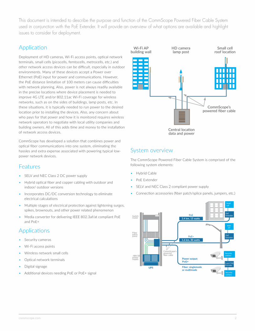
System overviewThe CommScope Powered Fiber Cable System is comprised of the following system elements:
• Hybrid Cable
• PoE Extender
• SELV and NEC Class 2 compliant power supply
• Connection accessories (fiber patch/splice panels, jumpers, etc.)
Wi-Fi AP building wall
Small cell roof location
HD camera lamp post
Central location data and power
CommScope’s powered fiber cable
Power output: PoE+
Fiber: singlemode or multimode
Smallcell
PoE Extender
PoE Extender
2 port PoE Extender
WiFi AP
Securitycamera
Securitycamera
CommScope’s powered fiber cable
2.4 km, 15 watts
1.6 km, 30 watts
PoE
PoE+
Switch router
Fiber patch panel
-48V DC power supply
UPS
commscope.com 3
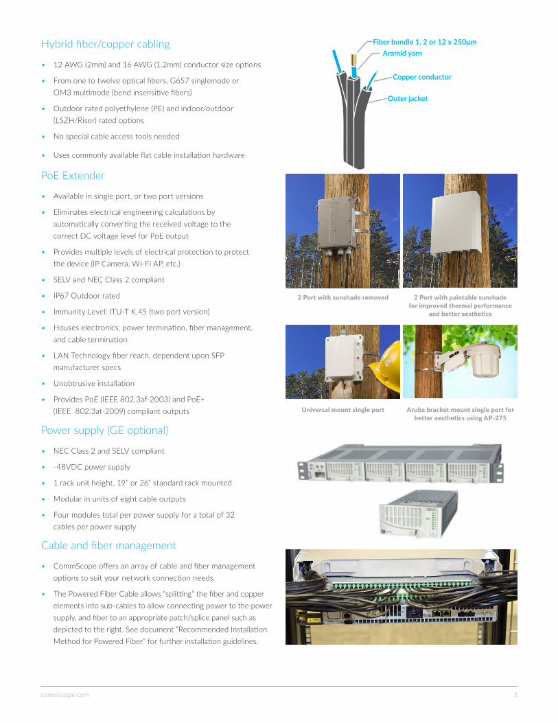
Hybrid fiber/copper cabling
• 12 AWG (2mm) and 16 AWG (1.2mm) conductor size options
• From one to twelve optical fibers, G657 singlemode or OM3 multimode (bend insensitive fibers)
• Outdoor rated polyethylene (PE) and indoor/outdoor (LSZH/Riser) rated options
• No special cable access tools needed
• Uses commonly available flat cable installation hardware
PoE Extender
• Available in single port, or two port versions
• Eliminates electrical engineering calculations by automatically converting the received voltage to the correct DC voltage level for PoE output
• Provides multiple levels of electrical protection to protect the device (IP Camera, Wi-Fi AP, etc.)
• SELV and NEC Class 2 compliant
• IP67 Outdoor rated
• Immunity Level: ITU-T K.45 (two port version)
• Houses electronics, power termination, fiber management, and cable termination
• LAN Technology fiber reach, dependent upon SFP manufacturer specs
• Unobtrusive installation
• Provides PoE (IEEE 802.3af-2003) and PoE+ (IEEE 802.3at-2009) compliant outputs
Power supply (GE optional)
• NEC Class 2 and SELV compliant
• -48VDC power supply
• 1 rack unit height, 19” or 26” standard rack mounted
• Modular in units of eight cable outputs
• Four modules total per power supply for a total of 32 cables per power supply
Cable and fiber management
• CommScope offers an array of cable and fiber management options to suit your network connection needs.
• The Powered Fiber Cable allows “splitting” the fiber and copper elements into sub-cables to allow connecting power to the power supply, and fiber to an appropriate patch/splice panel such as depicted to the right. See document “Recommended Installation Method for Powered Fiber” for further installation guidelines.
Fiber bundle 1, 2 or 12 x 250μmAramid yarn
Copper conductor
Outer jacket
2 Port with sunshade removed
Universal mount single port
2 Port with paintable sunshade for improved thermal performance
and better aesthetics
Aruba bracket mount single port for better aesthetics using AP-275
commscope.com 4
System configuration guidelinesThe power supply should be installed in a safe location with access to the fiber optic network and either 120VAC, 240VAC, or 48V power available. Small cells or other network access devices as needed can be connected to the power supply. Follow all manufacturer installation procedures.
The system has been designed such that there is no need for DC voltage drop calculations and/or system input modifications prior to delivery of the correct voltage and power levels to the network device.
Parameters requiring consideration to deploy the system are:
1. The distance from power supply to the network devices
a. This is important to determine the cable conductor size
2. The maximum power consumption of the network devices
a. Although the PoE and PoE+ standards allow for maximum device power consumption of 15.4 and 25.5W respectively, the actual power consumption of many devices may be less than these figures. Therefore, the maximum distances achievable for particular cameras, Wi- Fi APs, etc. may actually be greater than the full power allowed in PoE and PoE+ standards.
3. How many devices will be deployed
4. Installation considerations of the cable
a. Is indoor/outdoor (I/O) cabling required for building entries, or is purely outdoor rated (OSP) cable sufficient? Considerations include:
• The I/O cable has both Riser and LSZH ratings for in building deployment as well as carbon black impregnation and water blocking to withstand outdoor deployment
• The I/O cable has significantly higher friction pulling in ducts that the slicker surface of the OSP cable
• Also the OSP cable may be direct buried where the I/O cable cannot
b. If the unsupported aerial span length is 10 meters or more, the cable must be lashed or otherwise supported for aerial installation
c. Industry standard wedge clamps may be used for cable securing in aerial applications
d. Good cable installation practices including coupling loops should always be employed.
See Commscope App Note AN-107068a for guidance
5. Fiber management options
a. CommScope supports a complete portfolio of rack and wall mounted splice and patch solutions to connect the powered fiber cable system to your fiber network
Power supply options
While any NEC Class 2 and SELV compliant 48V DC power supply may be used, the CommScope recommended power supply is modular, with expansion capability to four modules. Each module can support powering up to eight hybrid cables. If eight or fewer devices are to be deployed initially, then only one module is needed. To power up to 16 cables, add a second module. Three modules are required for up to 24 cables. Four modules are required for up to 32 cables.
Although CommScope has thoroughly evaluated and tested one particular power supply from a major manufacturer, other power supplies from different vendors may be used. Please consult CommScope before utilizing such power supplies, as the voltage output of these may vary, affecting the maximum system distance achievable. A calculator tool to assist is available on http://www.commscope.com/poweredfiber/
Cable options
Based on max distance and power needed, the cable wire gauge (12AWG or 16AWG) may be selected based on the tables below.
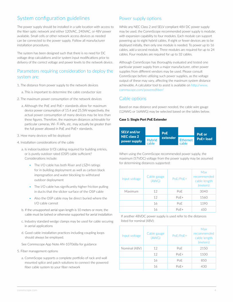
Case 1: Single Port PoE Extender
When using the CommScope recommended power supply, the maximum (57VDC) voltage from the power supply may be assumed for determining distances supported:
Input voltageCable gauge
(AWG)PoE/PoE+
Max recommended cable length
(meters)
Maximum 12 PoE 3040
12 PoE+ 1560
16 PoE 1190
16 PoE+ 610
If another 48VDC power supply is used refer to the distances listed for nominal (48V):
Input voltageCable gauge
(AWG)PoE/PoE+
Max recommended cable length
(meters)
Nominal (48V) 12 PoE 2150
12 PoE+ 1100
16 PoE 850
16 PoE+ 430
SELV and/or NEC class 2 power supply
PoE extenderHybrid
cableEthernet cable
PoE or PoE+ load
commscope.com 5
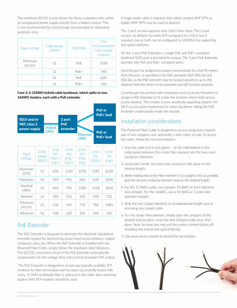
The minimum (40.5V) is only shown for those customers who utilize an unregulated power supply directly from a battery source. This is not recommended by CommScope, but provided for illustrative purposes only:
Input voltageCable gauge
(AWG)PoE/PoE+
Max recommended cable length
(meters)
Minimum (40.5V)
12 PoE 1530
12 PoE+ 780
16 PoE 600
16 PoE+ 310
Case 2: A 12AWG hybrid cable backbone, which splits to two 16AWG feeders, each with a PoE extender
Input voltage
Cable gauge (AWG)
Lmax (m)
(PoE+/PoE+)
Lmax (m)
(PoE/PoE+)
Lmax (m)
(PoE/PoE)
Lmax (m)
(PoE+)
Lmax (m)
(PoE)
Maximum (57V)
12 650 1120 1570 1595 2630
Maximum 16 255 445 620 630 1040
Nominal (48V)
12 460 795 1100 1120 1840
Nominal 16 180 315 435 440 725
Minimum (40.5V)
12 330 555 770 780 1285
Minimum 16 130 220 305 310 510
PoE ExtenderThe PoE Extender is designed to eliminate the electrical calculations normally needed for determining power level versus distance, copper conductor sizes, etc. When the PoE Extender is installed with the Powered Fiber Cable, simply follow the maximum rated distances. The DC/DC conversion circuit in the PoE Extender automatically compensates for line voltage drop and corrects to proper PoE output.
The PoE Extender is designed to accept any typically available SFP modules for fiber termination and has been successfully tested with many. If OM3 multimode fiber is selected in the cable, then matching duplex OM3 SFP modules should be used.
If single mode cable is selected, then either simplex SMF SFPs or duplex SMF SFPs may be used as desired.
The 1 port version supports only 1Gb/s fiber input. The 2 port version, by default, has both SFP configured for 1Gb/s, but if required, one or both can be configured to 100Mb/s for supporting low speed switches.
On the 1 port PoE Extenders, a single PoE and PoE+ compliant hardened RJ45 port is provided for output. The 2 port PoE Extender provides two PoE and PoE+ compliant ports.
CommScope has designed to power/communicate for a full 90 meters from this port, as specified in the PoE standards IEEE 802.3af and 802.3at, so the PoE Extender may be located anywhere up to this distance from the device to be powered and still function properly.
CommScope has worked with companies such as Aruba Networks to design a PoE Extender to fit inside the brackets which hold various access devices. This creates a more ascetically appealing solution for Wi-Fi access point deployment in urban situations, hiding the PoE Extender unobtrusively inside the bracket.
Installation considerationsThe Powered Fiber Cable is designed to access using only a typical pair of wire strippers and, optionally, a wire cutter or snip. To access the cable, follow this recommendation.
1. Snip the cable end in two places – at the indentations in the cable jacket between the center fiber element and the two outer conductor elements.
2. Using bare hands, first peel one conductor side away to the desired length.
3. While holding the center fiber element in as straight a line as possible, peel the second conductor element away to the desired length.
4. For the 12 AWG cable, use a proper 12 AWG or 2mm diameter wire stripper. For the 16AWG, use a 16 AWG or 1.2mm wire diameter stripper.
5. Strip the two copper elements to an appropriate length, just as accessing any copper cable.
6. For the center fiber element, simply place the strippers at the desired strip location, close the wire strippers fully once, then open. Now, by hand you may pull the center element jacket off, revealing the aramid and optical fiber(s).
7. Clip away excess aramid as desired for termination
SELV and/or NEC class 2 power supply
2 port PoE extenderHybrid
cableEthernet cable
PoE or PoE+ load
PoE or PoE+ load
commscope.comVisit our website or contact your local CommScope representative for more information.
© 2017 CommScope, Inc. All rights reserved.
All trademarks identified by ® or ™ are registered trademarks or trademarks, respectively, of CommScope, Inc. This document is for planning purposes only and is not intended to modify or supplement any specifications or warranties relating to CommScope products or services. CommScope is committed to the highest standards of business integrity and environmental sustainability, with a number of CommScope’s facilities across the globe certified in accordance with international standards, including ISO 9001, TL 9000, and ISO 14001. Further information regarding CommScope’s commitment can be found at www.commscope.com/About-Us/Corporate-Responsibility-and-Sustainability.
AN-111105.1-EN (05/17)
Everyone communicates. It’s the essence of the human experience. How we communicate is evolving. Technology is reshaping the way we live, learn and thrive. The epicenter of this transformation is the network—our passion. Our experts are rethinking the purpose, role and usage of networks to help our customers increase bandwidth, expand capacity, enhance efficiency, speed deployment and simplify migration. From remote cell sites to massive sports arenas, from busy airports to state-of-the-art data centers—we provide the essential expertise and vital infrastructure your business needs to succeed. The world’s most advanced networks rely on CommScope connectivity.
Cable installation
• For duct installation, the PE-jacketed outdoor-only rated cable is recommended. The LSZH/riser rated indoor/outdoor cable may also be installed in ducts - however, frictional forces are greater for the indoor/ outdoor cable and, therefore, achievable distances may be less. Standard cable lubricants may be used to assist with the indoor/outdoor cable for duct installation.
• When installing in ducts, care should be given to avoid cable twisting. This is easily achieved by paying off the cable from a reel. Never pull cable into ducts/conduit with twists as this reduces the achievable installation length. If it is not practical to bring a reel of cable to the installation site, then utilize a standard figure 8 procedure to lay the cable out prior to pulling in duct. This helps avoid cable twisting.
• The PE-jacketed outdoor cable is rated for direct burial. However, CommScope recommends always installing below-ground cables in conduit/ducts, as this is better for long-term reliability.
• For long aerial installation, cable lashing is recommended. The Powered Fiber Cable is not rated for aerial self-support.
• Always use good cable installation methods including use of coupling coils. See Commscope App Note AN-107068a for guidance.
For more information, see http://www.commscope.com/poweredfiber/