powerflex 20-750-pbus profibus dpv1 option module user manual · configure, and monitor a powerflex...
TRANSCRIPT

38 Rockwell Automation Publication 750COM-UM004A-EN-P - August 2011
Chapter 4 Configuring the Profibus Master
GSD Installation ProSoft Configuration Builder (PCB) uses Profibus slave definition files (GSD files) to obtain basic configuration information about the Profibus slaves you add to the network. The GSD configuration files identify the slave's capabilities so that the MVI56-PDPMV1 module can communicate with it correctly.
For example: The 20-750-PBUS GSD file is named "20750D3B.gsd". It is the GSD file for the drive’s 20-750-PBUS Option Module and can be downloaded from http://www.ab.com/support/abdrives/webupdate. The configuration tool only requires the 20-750-PBUS GSD file for the 20-750-PBUS Option Module to be registered one time in this tool for configuring networks with this Option Module.
Follow these steps to install the GSD file or files for your slave module or modules.
1. Open the Tools menu, and choose Install new GS*-file... (Figure 21).
Figure 21 - Installing the GSD File
2. This action opens a dialog box that allows you to browse for the location of the GSD (Figure 22).
Figure 22 - Selecting the GSD File
Rockwell Automation Publication 750COM-UM004A-EN-P - August 2011 39
Configuring the Profibus Master Chapter 4
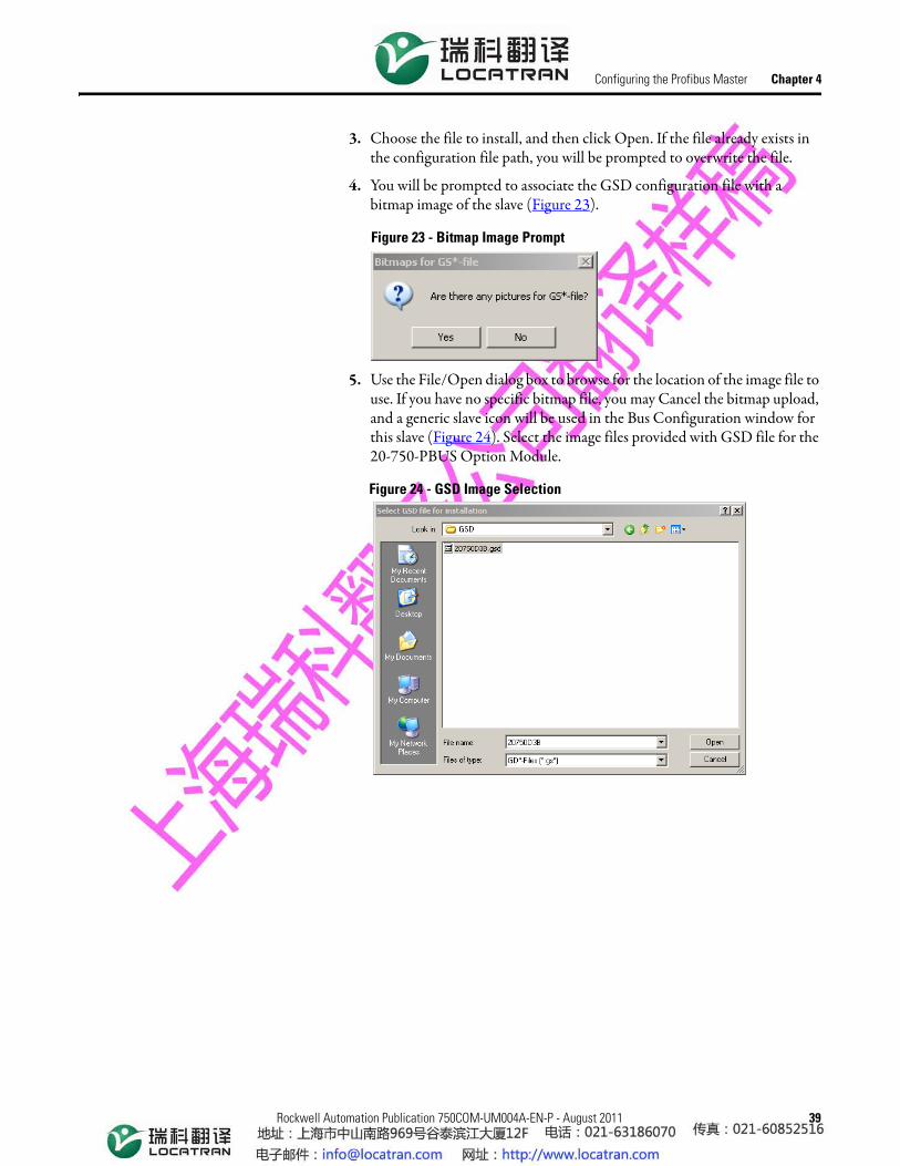
3. Choose the file to install, and then click Open. If the file already exists in the configuration file path, you will be prompted to overwrite the file.
4. You will be prompted to associate the GSD configuration file with a bitmap image of the slave (Figure 23).
Figure 23 - Bitmap Image Prompt
5. Use the File/Open dialog box to browse for the location of the image file to use. If you have no specific bitmap file, you may Cancel the bitmap upload, and a generic slave icon will be used in the Bus Configuration window for this slave (Figure 24). Select the image files provided with GSD file for the 20-750-PBUS Option Module.
Figure 24 - GSD Image Selection

40 Rockwell Automation Publication 750COM-UM004A-EN-P - August 2011
Chapter 4 Configuring the Profibus Master
6. This will prompt a screen showing the newly added slave in the treeview (Figure 25).
Figure 25 - Selected Slave in Device List Treeview
Slave Configuration The following steps describe how to add and configure a 20-750-PBUS Option Module as a Slave.
1. In ProSoft Configuration Builder tool, click the plus sign [+] to expand the PROFIBUS DP treeview (Figure 26).
Figure 26 - Device Configuration - Available Options

Rockwell Automation Publication 750COM-UM004A-EN-P - August 2011 41
Configuring the Profibus Master Chapter 4
2. Navigate to the Drives/Allen-Bradley folder containing the 20-750-PBUS Slave to add, and then click the plus sign [+] to expand the folder.
3. Drag the Slave icon into the Bus Configuration window. This action adds the slave to the Profibus network and configures it to the Master in a networked relationship (Figure 27).
Figure 27 - Adding 20-750-PBUS Slave Module
4. In the treeview, click the plus sign [+] to expand the slave you added. This action opens a list of device configuration values. Figure 27 shows the possible input/output configuration values for a 20-750-PBUS Slave. The Datalinks (1-16) allow the assignment of configured drive parameters to be included in the Profibus DP I/O data frames that are transferred between the ControlLogix PLC and the PowerFlex 750-Series drive.

42 Rockwell Automation Publication 750COM-UM004A-EN-P - August 2011
Chapter 4 Configuring the Profibus Master
5. Drag the input and output parameters to the Slot Location Grid (Subscriber List) below the Bus Configuration window. This view displays the slot number, configuration data, and starting input and output addresses that will be assigned in the PLC memory for the MVI56-PDPMV1 module. The MVI56-PDPMV1 Master uses this information to identify and communicate with individual slaves on the network (Figure 28).
Figure 28 - Inserting Ctrl/Stat & Ref/Fdbk (Device Configuration) into Slot 1
For this example, we will configure words of Ctrl/Stat & Ref/Fdbk. These input and output 32-bit values are assigned to addresses within the MVI56-PDPMV1 module's internal database. For each new slave added to the Profibus network, PCB automatically converts the input/output byte addresses to input and output image addresses for the tag database in the ControlLogix processor.
6. Likewise add as many modules as required. All the modules from Ctrl/Stat & Ref/Fdbk to Datalink16 can be added (Figure 29).
Figure 29 - Inserting Configuration Options into all Slots

Rockwell Automation Publication 750COM-UM004A-EN-P - August 2011 43
Configuring the Profibus Master Chapter 4
7. Double-click the Slave icon to view the Slave Properties or right-click on the slave icon and select Object Properties as shown in Figure 30.
Figure 30 - Choosing Slave Properties
8. PCB automatically assigns a Profibus address to each new slave. The address assignment begins at address 3, and is incremented by 1 for each new slave added to the network. You can change the address in the Common tab of the Slave properties dialog box. The address should match the PowerFlex 750-Series drive’s Profibus address assigned for the specific drive you are configuring. PCB will not allow you to assign a Profibus address that is already in use by another module on this network (Figure 31).
Figure 31 - Profibus Address Selection

44 Rockwell Automation Publication 750COM-UM004A-EN-P - August 2011
Chapter 4 Configuring the Profibus Master
9. Click on the value selection of the DP Mode parameter and, from the drop down list, select DPV1 (Figure 32).
Figure 32 - DP Mode Selection
10. Click on the value selection of the Diagnostic Alarm parameter and, from the drop down list, select Enabled (Figure 33).
Figure 33 - Enabling Diagnostic Alarm
Rockwell Automation Publication 750COM-UM004A-EN-P - August 2011 45
Configuring the Profibus Master Chapter 4
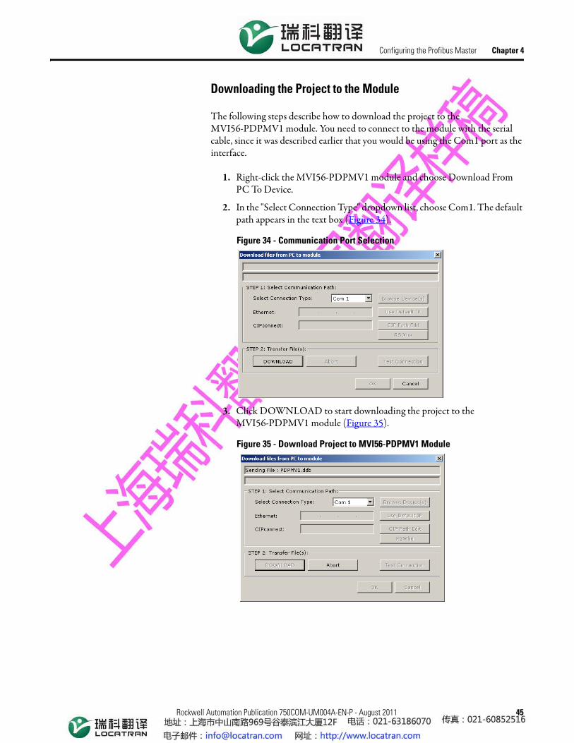
Downloading the Project to the Module
The following steps describe how to download the project to the MVI56-PDPMV1 module. You need to connect to the module with the serial cable, since it was described earlier that you would be using the Com1 port as the interface.
1. Right-click the MVI56-PDPMV1 module and choose Download From PC To Device.
2. In the "Select Connection Type" dropdown list, choose Com1. The default path appears in the text box (Figure 34).
Figure 34 - Communication Port Selection
3. Click DOWNLOAD to start downloading the project to the MVI56-PDPMV1 module (Figure 35).
Figure 35 - Download Project to MVI56-PDPMV1 Module

46 Rockwell Automation Publication 750COM-UM004A-EN-P - August 2011
Chapter 4 Configuring the Profibus Master
4. After the configuration is transferred, it will automatically start rebooting of the MVI56-PDPMV1 module (Figure 36).
Figure 36 - MVI56-PDPMV1 Module Rebooting
5. After rebooting the MVI56-PDPMV1 module, you can view the status of download (Figure 37).
Figure 37 - Download Completed

Rockwell Automation Publication 750COM-UM004A-EN-P - August 2011 47
Chapter 5
Using the I/O
This chapter provides information and examples that explain how to control, configure, and monitor a PowerFlex 750-Series drive using Profibus DPV0 messaging.
About I/O Messaging Profibus DPV0 or I/O messaging is used to transfer the data which controls the PowerFlex drive and its Reference. I/O messaging can also be used to transfer data to and from Datalinks which are mapped to parameters in the PowerFlex 750-Series drives.
The Option Module includes the Logic Command, Logic Status, Reference, and Feedback (32-bit words) in the controller’s I/O image. This basic I/O must always be configured by the Profibus configuration tool to the 20-750-PBUS Option Module, enabling the ability to control and monitor the PowerFlex 750-Series drive.
Additional I/O if needed, can be configured using up to 16 Datalinks to write data and/or up to 16 Datalinks to read data. When using any combination of these Datalinks, one 32-bit word for each Datalink will be added to the basic I/O Input Size and/or Output Size.
Chapter 3, Configuring the Option Module, and Chapter 4, Configuring the Profibus Master discuss how to configure the Option Module and controller on the network for the required I/O.
Topic PageAbout I/O Messaging 47Understanding the I/O Image 48Using Logic Command/Status 48Using Reference/Feedback 49Using Datalinks 49I/O Communication 51
ATTENTION: Risk of injury or equipment damage exists. The examples in this publication are intended solely for purposes of example. There are many variables and requirements with any application. Rockwell Automation, Inc. does not assume responsibility or liability (to include intellectual property liability) for actual use of the examples shown in this publication.

48 Rockwell Automation Publication 750COM-UM004A-EN-P - August 2011
Chapter 5 Using the I/O
Understanding the I/O Image
The terms input and output are defined from the controller’s point of view. Therefore, output I/O is data that is produced by the controller and consumed by the Option Module. Input I/O is status data that is produced by the Option Module and consumed as input by the controller. The I/O image will vary based on how many of the drive’s 32-bit Datalinks (Host DL From Net 01-16 and Host DL To Net 01-16) are used.
Profibus Master Image
The I/O image can be configured based upon the number of Datalinks required by the user. Table 3 shows the I/O image when using all of the 32-Bit Datalinks.
Table 3 - Profibus Master I/O Image for PowerFlex 750-Series Drives (32-bit Logic Command/Status, Reference/Feedback, and Datalinks)
Using Logic Command/Status
The Logic Command is a 32-bit word of control data produced by the controller and consumed by the Option Module. The Logic Status is a 32-bit word of status data produced by the Option Module and consumed by the controller.
• Logic Command word is always the first 32-bit word in the output image.• Logic Status word is always the first 32-bit word in the input image.
This manual contains the bit definitions for compatible products available at the time of publication in Appendix C, Logic Command/Status Words: PowerFlex 750-Series Drives.
DINT Output I/O DINT Input I/O0 Logic Command 0 Logic Status1 Reference 1 Feedback2 DL From Net 01 2 DL To Net 013 DL From Net 02 3 DL To Net 024 DL From Net 03 4 DL To Net 035 DL From Net 04 5 DL To Net 046 DL From Net 05 6 DL To Net 057 DL From Net 06 7 DL To Net 068 DL From Net 07 8 DL To Net 079 DL From Net 08 9 DL To Net 0810 DL From Net 09 10 DL To Net 0911 DL From Net 10 11 DL To Net 1012 DL From Net 11 12 DL To Net 1113 DL From Net 12 13 DL To Net 1214 DL From Net 13 14 DL To Net 1315 DL From Net 14 15 DL To Net 1416 DL From Net 15 16 DL To Net 1517 DL From Net 16 17 DL To Net 16

Rockwell Automation Publication 750COM-UM004A-EN-P - August 2011 49
Using the I/O Chapter 5
Using Reference/Feedback The Reference is a 32-bit REAL (floating point) piece of control data produced by the controller and consumed by the Option Module. The Feedback is a 32-bit REAL (floating point) piece of status data produced by the Option Module and consumed by the controller.
• Reference word is always the second 32-bit word in the output image.• Feedback word is always the second 32-bit word in the input image.
The Reference and Feedback 32-bit REAL value represents drive speed. The scaling for the speed Reference and Feedback are dependent on drive Parameter 300 - [Speed Units]. For example, if Parameter 300 is set to Hz, a 32- bit REAL Reference value of "30.0" would equal a Reference of 30.0 Hz. If Parameter 300 is set to RPM, a 32- bit REAL Reference value of "1020.5" would equal a Reference of 1020.5 RPM. Note that the commanded maximum speed can never exceed the value of drive Parameter 520 - [Max Fwd Speed]. Table 4 shows example References and their results for a PowerFlex 750-Series drive that has its:
• Parameter 300 - [Speed Units] set to Hz.• Parameter 37 - [Maximum Freq] set to130 Hz.• Parameter 520 - [Max Fwd Speed] set to 60 Hz.
When Parameter 300 - [Speed Units] is set to RPM, the other parameters are also in RPM.
Table 4 - PowerFlex 750-Series Drive Example Speed Reference/Feedback Scaling
Using Datalinks A Datalink is a mechanism used by PowerFlex drives to transfer data to and from the controller. Datalinks allow a drive parameter value to be read or written to without using a Profibus DPV1 Service. When enabled, each Datalink occupies one 32-bit word in a ControlLogix controller, providing a mirror of the PowerFlex 750-Series drive data value that the Datalinked parameter represents.
The following rules apply when using PowerFlex 750-Series drive Datalinks:
• The target of a Datalink can be any Host parameter, including those of a peripheral. For example, drive parameter 535 - [Accel Time 1] can be the target of any or all Option Modules installed in the drive.
Network Reference Value Speed Command Value
(2)
(2) For this example, drive parameter 300 - [Speed Units] is set to Hz.
Output Speed Network Feedback Value
130.0 130 Hz 60 Hz (3)
(3) The drive runs at 60 Hz instead of 130 Hz or 65 Hz because drive Parameter 520 - [Max Fwd Speed] sets 60 Hz as the maximum speed.
60.065.0 65 Hz 60 Hz (3) 60.032.5 32.5 Hz 32.5 Hz 32.50.0 0 Hz 0 Hz 0.0-32.5 (1)
(1) The effects of values less than 0.0 depend on whether the PowerFlex 750 - Series drive uses a bipolar or unipolar direction mode. See the drive documentation for details.
32.5 Hz 32.5 Hz 32.5

50 Rockwell Automation Publication 750COM-UM004A-EN-P - August 2011
Chapter 5 Using the I/O
• The data passed through the Datalink mechanism is determined by the settings of Host Parameters 01...16 - [DL From Net 01-16] and Host Parameters 17...32 - [DL To Net 01-16].
• When an I/O connection that includes Datalinks is active, those Datalinks being used are locked and cannot be changed until that I/O connection becomes idle or inactive.
• When you use a Datalink to change a value, the value is NOT written to the Non-Volatile Storage (NVS). The value is stored in volatile memory and lost when the drive loses power. Thus, use Datalinks when you need to change a value of a parameter frequently.
Datalinks for PowerFlex 750-Series peripherals (embedded EtherNet/IP adapter and Option Modules such as an encoder or a communication module) are locked when the peripheral has an I/O communication with a controller. When a controller has an I/O communication to the drive, the drive does not allow a reset to defaults, configuration download or anything else that could change the makeup of the I/O communication in a running system. The I/O communication with the controller must first be disabled to allow changes to the respective Datalinks.
Depending on the controller being used, the I/O connection can be disabled by:• Putting the controller in Program mode• Disconnecting the drive from the network• Placing the master in idle mode
DeviceLogix Datalinks are also locked while the DeviceLogix program is running. The DeviceLogix program must first be disabled to allow changes to the Datalinks. Set DeviceLogix parameter 53 - [DLX Operation] to “DisableLogic” to disable the logic (the parameter value will then change to “LogicDisabld”).
IMPORTANT A reset is always required after configuring Datalinks so that the changes take effect.
TIP A COP (Copy) instruction or a UDDT is needed—for REAL parameters, speed Reference, and speed Feedback only—to copy the DINT data into a REAL word for input data conversion. For output data conversion, a COP (Copy) instruction or UDDT is needed—for REAL parameters, speed Reference, and speed Feedback only—to copy the REAL data into a DINT word. To determine whether a parameter is a 32-bit integer (DINT) or a REAL data type, see the Data Type column in the chapter containing parameters in the PowerFlex 750-Series AC Drives Programming Manual (publication 750-PM001).

Rockwell Automation Publication 750COM-UM004A-EN-P - August 2011 51
Using the I/O Chapter 5
I/O Communication The following example describes how to use Profibus DPV0 I/O communication for the ControlLogix for Profibus master - MVI56-PDPMV1.
I/O data transferred to and from the 20-750-PBUS Option Module nodes can be viewed in the MVI56-PDPMV1 ControlLogix controller tags for the DPV0 cyclic communication connections. See Figure 38 and Figure 39 for input and output mapping in the MVI56-PDPMV1.
Figure 38 - Input Mapping in the MVI56-PDPMV1
Figure 39 - Output Mapping in the MVI56-PDPMV1
52 Rockwell Automation Publication 750COM-UM004A-EN-P - August 2011
Chapter 5 Using the I/O
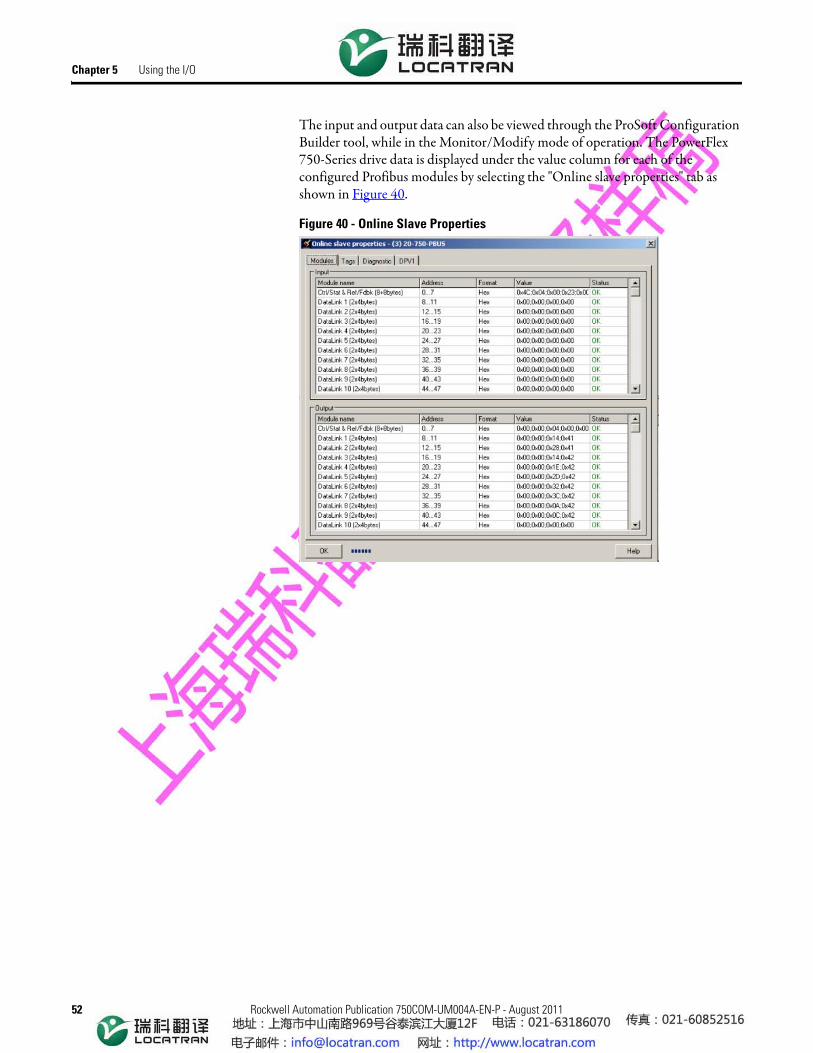
The input and output data can also be viewed through the ProSoft Configuration Builder tool, while in the Monitor/Modify mode of operation. The PowerFlex 750-Series drive data is displayed under the value column for each of the configured Profibus modules by selecting the "Online slave properties" tab as shown in Figure 40.
Figure 40 - Online Slave Properties