powering the mine - etap
TRANSCRIPT

Powering the Mine Intergraph® SmartPlant® Electrical and ETAP®
Powering the Mine
i
Contents
1. Introduction ................................................................................................................. 1
1.1. Credits ............................................................................................................................................. 1
2. Rising Cost of Mining .................................................................................................. 2
3. Strategic and Sustainable Solution.............................................................................. 4
3.1. Goals ............................................................................................................................................... 4 3.1.1. Centralized Approach ............................................................................................................ 4 3.1.2. Standardization ...................................................................................................................... 4 3.1.3. Engineering and Design Basis ............................................................................................... 4 3.1.4. Real-time Management System ............................................................................................. 4
3.2. Enterprise Solution .......................................................................................................................... 4
4. Importance of the Electrical Distribution System for Mines ........................................ 5
4.1. Availability Criteria ........................................................................................................................... 5 4.2. Breakdowns ..................................................................................................................................... 5
4.3. Regulatory Issues ............................................................................................................................ 5
5. Mining Electrical Engineering Challenges ................................................................... 7
5.1. Schedule .......................................................................................................................................... 7
5.2. Multiple Inputs ................................................................................................................................. 7
5.3. Safety ............................................................................................................................................... 7 5.4. Standardization ................................................................................................................................ 7
5.5. Change Management ...................................................................................................................... 7
5.6. Beyond Design ................................................................................................................................ 7
5.7. Power Management ........................................................................................................................ 8
5.8. System Sustainability ...................................................................................................................... 8
6. Unique Solution from Intergraph and ETAP ................................................................ 9
6.1. Data-centric Design ......................................................................................................................... 9 6.2. Relationships ................................................................................................................................... 9
6.3. Built-in Rules.................................................................................................................................... 9
6.4. Deliverables ..................................................................................................................................... 9
7. Powerful Combined Solution ..................................................................................... 10
7.1. ETAP ............................................................................................................................................. 10
7.2. SmartPlant Electrical ..................................................................................................................... 10

Powering the Mine
i
8. Sample Workflow ...................................................................................................... 12
8.1. Loads ............................................................................................................................................. 12
8.2. Designing the System .................................................................................................................... 12
8.3. Balancing the Load ........................................................................................................................ 13 8.4. Validating the Design ..................................................................................................................... 13
8.4.1. Design and Analysis ............................................................................................................ 13 8.4.2. Power Management System ................................................................................................ 14 8.4.3. Analysis and Simulation ....................................................................................................... 14 8.4.4. Intelligent Load Shedding .................................................................................................... 15 8.4.5. Deliverables ......................................................................................................................... 15
8.5. Schematics .................................................................................................................................... 18
8.6. Routing Cables .............................................................................................................................. 19
8.7. Deliverables ................................................................................................................................... 20
8.8. Making the Changes ...................................................................................................................... 21 8.8.1. Concurrent Processes ......................................................................................................... 21
8.9. Operations ..................................................................................................................................... 22
9. Business Benefits ...................................................................................................... 23
10. Conclusion .............................................................................................................. 24
11. References .............................................................................................................. 25
11.1. Sinclair Knight Merz, Australia..................................................................................................... 25 11.1.1. SKM Selects Intergraph SmartPlant Enterprise, Including SmartPlant Electrical ............. 25
11.2. Lonmin Plc, South Africa ............................................................................................................. 26 11.2.1. ETAP Power System Monitoring and Optimization Deployed by Lonmin Plc ................... 26
11.3. PT Newmont Nusa Tenggara, Indonesia .................................................................................... 27 11.3.1. PT Newmont Nusa Tenggara Uses the ETAP Enterprise Solution to Monitor, Control and Optimize Its Electrical Power Generation and Transmission ......................................................... 27 11.3.2. ETAP Intelligent Load Shedding Deployed at One of Indonesia’s Largest Copper-Gold Mines .............................................................................................................................................. 28
8. Sample Workflow ......................................................................................................

Powering the Mine
1
1. Introduction Intergraph® SmartPlant® Electrical working with ETAP® can help to achieve business objectives and offer a unique solution in the market of engineering, design, validation of data, construction support, commission, and operations.
1.1. Credits
This document was created by Intergraph with the support of the Mining and Metals Division of Sinclair Knight Merz.
Powering the Mine
2
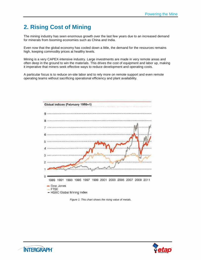
2. Rising Cost of Mining The mining industry has seen enormous growth over the last few years due to an increased demand for minerals from booming economies such as China and India.
Even now that the global economy has cooled down a little, the demand for the resources remains high, keeping commodity prices at healthy levels.
Mining is a very CAPEX-intensive industry. Large investments are made in very remote areas and often deep in the ground to win the materials. This drives the cost of equipment and labor up, making it imperative that miners seek effective ways to reduce development and operating costs.
A particular focus is to reduce on-site labor and to rely more on remote support and even remote operating teams without sacrificing operational efficiency and plant availability.
Figure 1: This chart shows the rising value of metals.

Powering the Mine
3
In too many cases, executed projects suffer overruns in both budget and schedule, placing projects at risk or significantly reducing the rate of return to the owners. Some of the reasons for this are:
Limited availability of skilled labor.
Excess demand on the supply chain.
Remote and unpredictable environments in which mines must work.
Cost of equipment and construction.
Some of these are not easy to control, but others can be controlled by using new engineering solutions to lower design risks and to reduce operating costs.
Safety is certainly also a concern for owners, and again, new technology and improved information management can be applied to maintain the highest possible standards.
The bottom line is that the cost of mining has increased approximately 30 percent more than the consumer price index (CPI) over the last 10 years.
Figure 2: The capital operating cost of mines and mineral processing has risen dramatically over the last decade.
Powering the Mine
4
3. Strategic and Sustainable Solution
3.1. Goals
3.1.1. Centralized Approach
Owners are looking for a strategic and sustainable solution. What does that mean? For example, the cost of maintaining the mine is about 30 percent of OPEX, so several customers are looking at a centralized approach for maintenance to reduce this cost and increase the availability of the mine. This is sometimes referred to as a thin operating model. A small local team is supported by a remote expert team serving several locations, leveraging experiences and resources.
3.1.2. Standardization
An important strategy to pursue is standardization. Some owners are looking to standardize up to 80 percent of their business processes, eliminating duplication of systems and minimizing inconsistency in equipment, design tools, and design standards.
If a company with many sites cannot interchange resources, there can be a big impact on the cost of the business for running duplicate systems and for plant maintenance and upgrades.
3.1.3. Engineering and Design Basis
Another important aspect is the engineering and design basis. This is the collection of all of the engineering and design data and related documents for the mine. To have access to this and to keep it current is an essential component to lower the risk and cost of operations and maintenance. Key to this is to minimize equipment failure and the “mean time to repair” by ensuring that all information is instantly available, fully up to date, easy to maintain, and also easy to apply to site design upgrades.
3.1.4. Real-time Management System
Once the design and engineering are finalized, the maintenance and operation of the facility can be monitored and optimized through a real-time management system.
3.2. Enterprise Solution Using a fully-integrated enterprise solution for design, simulation, operation, control, optimization, and automation accomplishes the objective of standardization and centralized collection of data and information for the life cycle of the plant. This data will provide a quick and accurate picture at any moment for the operators or maintenance teams (local or remote) to make the right decision quickly on safety, condition monitoring, breakdown response, and maintenance issues. This engineering and design basis links to other systems, such as the enterprise resource plan (e.g., SAP), control systems like DeltaV from Emerson, or Experion from Honeywell.
Powering the Mine
5
4. Importance of the Electrical Distribution System for Mines In this paper, we are focusing on the electrical distribution system for mines.
4.1. Availability Criteria Electrical systems are absolutely important in these installations, with demanding availability criteria of typically 99.8 percent.
4.2. Breakdowns Electrical system breakdowns will immediately stop production, incurring huge costs and possibly endangering personnel.
4.3. Regulatory Issues
A well-designed, well-maintained, and clearly documented electrical design is not only imperative for reasons of safety and cost, but it regulatory requirements typically specify that the electrical system is up-to-date and covers issues such as:
System and equipment loading.
Fault ratings and arc flash analysis.
Switching instructions and safety interlocks.
Effective earthing and controlled step and touch potentials.
Protection coordination and relay setting files.
Transient stability studies.
Load-shedding scenarios.
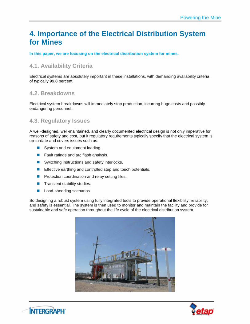
So designing a robust system using fully integrated tools to provide operational flexibility, reliability, and safety is essential. The system is then used to monitor and maintain the facility and provide for sustainable and safe operation throughout the life cycle of the electrical distribution system.

Powering the Mine
6
Figure 3: The electrical distribution system life cycle covers five main phases.
Intelligent Modeling Environment Integrated Analysis Tools Rule-Based Driven Design
Engineering & Schematics Equipment (Load, Cable, etc.)
Management Revisions & Version Control
Information Management Work Flow & Permits Records Management
Power Management - Real-Time Monitoring & “What If” Analysis Automated Optimal Control Intelligent Load Shedding
Asset Management Power Management Workflow Emergency Recovery
Powering the Mine
7
5. Mining Electrical Engineering Challenges The key in all of this is a clear definition of ownership and accountability as well as a strong system for managing data consistently in an ever-changing environment. In addition, there is a need to accelerate the learning of new tools and processes and to improve collaboration between all teams and parties involved. There is a lot to think about to make it all work on time and within budget, so having the use of a quality design tool is invaluable.
5.1. Schedule The electrical engineering discipline faces many challenges. It is often trailing the project schedule, being the last to finish as final loads and last-minute additions impact the design. Efforts to fast-track projects make matters worse and can negatively impact design quality.
5.2. Multiple Inputs The electrical engineer is also on the receiving end of information from many different parties, such as the instrument group, the vendors, the mechanical team, and the building and infrastructure team. All of these inputs need to be compiled and correctly connected into the power system.
5.3. Safety Safety is a continuous challenge: The design needs to be reliable and protective devices well-coordinated. Fault limitation is critical. Hazardous area classifications must be carefully compiled and engineered, especially in mines where there can be explosive dust and gases.
5.4. Standardization As mentioned before, standardization is a key goal for owners. This means that the design and the selection of equipment must be consistent, installation and maintenance issues must be carefully included, and documentation must be complete to a high quality and readily available. Then the thin maintenance model can be achieved. This can significantly reduce the cost of maintenance and unscheduled downtime.
5.5. Change Management
Of course, the only thing that is certain in engineering is change. These changes need to be managed closely. Documentation needs to be updated across the project to reflect the latest version of the design. As a follow-up to the continuous changes, model validation needs to be addressed as a combination effort between the engineering group and the operations group.
5.6. Beyond Design Apart from the conceptual design, many practicalities must be included, such as cable routing, placement of panels, and space for operating and maintaining equipment. After that, everything must be procured and delivered to site in the right quantities at the right time.
Powering the Mine
8
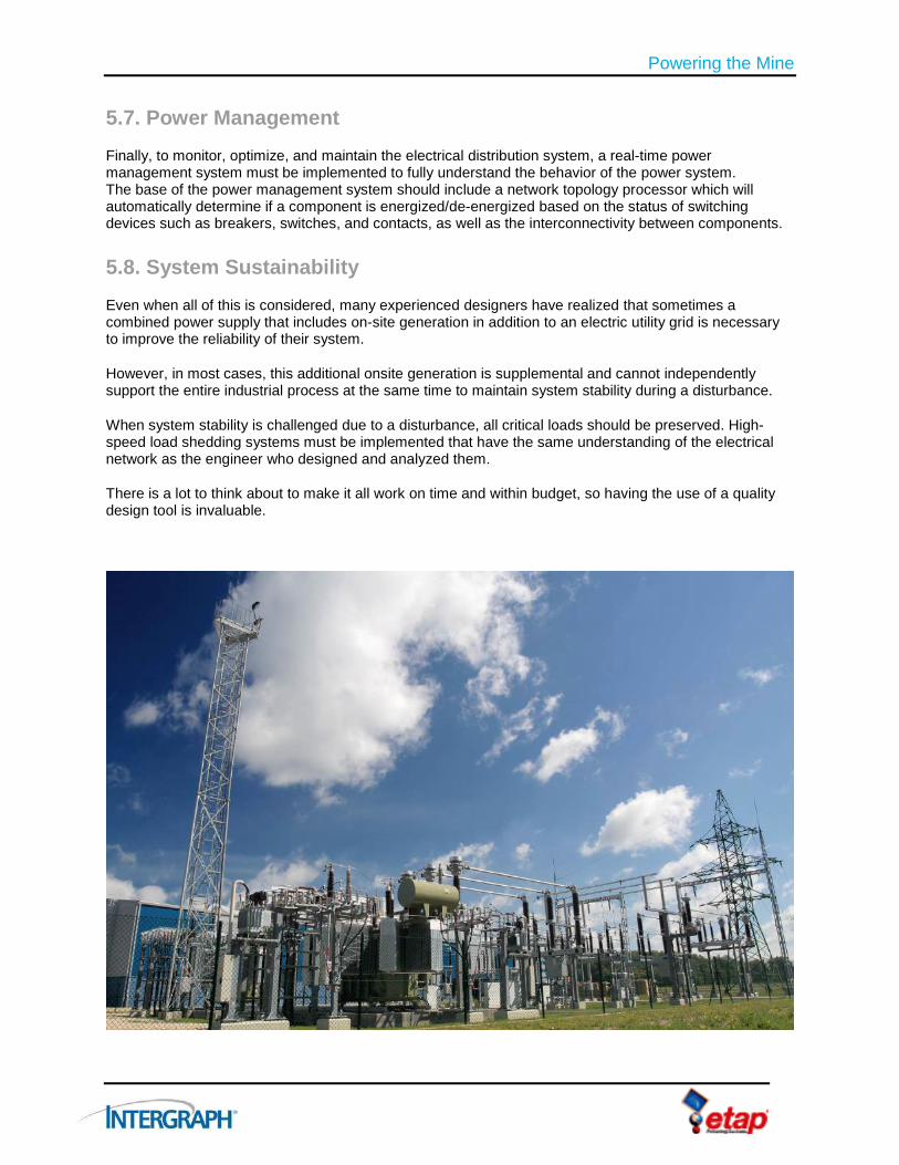
5.7. Power Management Finally, to monitor, optimize, and maintain the electrical distribution system, a real-time power management system must be implemented to fully understand the behavior of the power system. The base of the power management system should include a network topology processor which will automatically determine if a component is energized/de-energized based on the status of switching devices such as breakers, switches, and contacts, as well as the interconnectivity between components.
5.8. System Sustainability
Even when all of this is considered, many experienced designers have realized that sometimes a combined power supply that includes on-site generation in addition to an electric utility grid is necessary to improve the reliability of their system.
However, in most cases, this additional onsite generation is supplemental and cannot independently support the entire industrial process at the same time to maintain system stability during a disturbance.
When system stability is challenged due to a disturbance, all critical loads should be preserved. High-speed load shedding systems must be implemented that have the same understanding of the electrical network as the engineer who designed and analyzed them.
There is a lot to think about to make it all work on time and within budget, so having the use of a quality design tool is invaluable.

Powering the Mine
9
6. Unique Solution from Intergraph and ETAP Intergraph can help you with solutions for your electrical engineering challenges within your mining facilities.
Together with our long-standing partner ETAP, Intergraph offers a unique electrical engineering and design solution combining ETAP enterprise solution software for power systems with SmartPlant Electrical to fit the work process and challenges of the mining industry. This solution is applicable to the project development phase as well as to the operation and maintenance of the plant.
The solution has been designed with and for the industry, and has a proven track record in the mining industry.
6.1. Data-centric Design
The design is data-centric, in contrast to traditional CAD and Microsoft® Excel®-based tools. The drawings, reports, and other deliverables are a view from that single source of data.
6.2. Relationships
The next fundamental differentiator is relationships. The system “knows” what equipment is connected together with what cable – all of the time. Network topology not only displays connectivity between devices, but will also look at the status of switching devices, such as breakers, switches, and contacts. This connectivity is absolutely key to driving consistency throughout the design.
6.3. Built-in Rules
Rules within the Intergraph system are automated instructions that can be run within the design. With consistent data and fixed relationships, we can execute rules against those relationships and data to determine if it is a valid design based on your practices, industry practices, and client standards.
This helps you make the right decision early and avoid costly changes later in the design process which could negatively impact schedule and budget.
6.4. Deliverables The real benefit with this system is that with the data and relationships all stored in one location, you can create many deliverables that fit the task at hand.
For installations, you may want certain wiring/termination reports.
For operations, you may want system drawings for troubleshooting, repairs, and minor upgrades.
For commissioning, you may want one-line drawings and circuit diagrams.
All of these documents can be produced as reports on the database, and therefore always represent the current data.
The data and the generated reports can be accessed from remote locations, so the system fits with the thin maintenance model.

Powering the Mine
10
7. Powerful Combined Solution ETAP and Intergraph’s SmartPlant Electrical exchange data to help you maintain consistency. Together, they make a very powerful design, analysis, and automation system.
This section explores the tools and environment that enable the design to be clear, easy to use, and fit for the task.
7.1. ETAP ETAP is the market-leading electrical analysis solution. It offers an enterprise solution for design, analysis, operation, and automation. ETAP will carry out the power system analysis to confirm a variety of elements, including:
Load flows.
Fault levels.
Protection requirements.
Arc flash analysis.
Transient stability studies.
Load-shedding operations
7.2. SmartPlant Electrical SmartPlant Electrical is used to design power distribution systems and to create associations between equipment and cabling.
There are six SmartPlant Electrical user modules that support the engineer and designer:
Electrical Engineer – Enables the user to create the layout and design the power distribution network.
Electrical Index – Contains all project-specific equipment (with names and tags) with associated data displayed in the Properties Window.
Properties Window – Displays the data associated with the electrical items, such as cables, equipment, panels, motors, and transformers.
Reference Data Explorer – Contains best practice or client-specific equipment and standard items to be used in the project, such as defined cables, motors, and transformers, together with the technical data associated with this equipment. This drives consistency in equipment selection and specification.
Reference Electrical Engineer – Provides the ability to copy and reuse existing designs as a whole or in part.
Engineering Editor – Enables project data editing and searching. This is particularly useful for mass data editing and searching across the project.
Powering the Mine
11
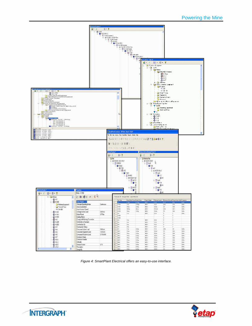
Figure 4: SmartPlant Electrical offers an easy-to-use interface.

Powering the Mine
12
8. Sample Workflow This sample workflow will demonstrate some high-level steps to explain how the solution works.
The solution is flexible, which means it can adapt to your specific work process and make use of local standard symbols and custom deliverables.
8.1. Loads The fundamental data for any electrical design are, of course, the loads. These can be easily imported from other legacy data sources such as SmartPlant P&ID, the mechanical team, control systems designers, vendor data (if available), or they can be entered manually into the SmartPlant Electrical application itself.
If loads are not exactly known – for example, when a vendor has not been selected – a temporary value can be entered to allow the design to progress. The final data can be added later. With the management of change and built-in rules, the system will provide automation to keep the data consistent throughout the design.
Alternatively, if a feasibility study is performed using the ETAP solution and SmartPlant Electrical is not used in that phase of the project, the design can be imported from ETAP to SmartPlant Electrical to begin the detailed design process.
This capability offers a very productive way to quickly create the load list, the initial electrical one-line diagrams, and the power system model in a single process.
8.2. Designing the System
Based on scope, site layout, and local and client practices, the engineer can now begin the process of laying out the electrical network and distribution system using SmartPlant Electrical cable block diagrams. These cable block diagrams will help the engineer to arrange the main distribution points and connections.
The loads can then be dragged and dropped onto the power distribution tree in the Electrical Engineer module. This environment shows the connectivity of the system and all of the associated loads. It is easy to manipulate the position of the loads by dragging and dropping onto other panels.
At any point in time, you can create a one-line diagram from the system to check what this looks like. The user can then choose to generate a drawing of the complete system or any part of the system with a few simple selections.
It is important to mention that loads can be associated with best-practice configurations. When assigned to a switchgear or Motor Control Center, they automatically inherit all of the components to make up the circuit, such as the circuit breaker, protective devices, switches, and cables.
In addition, the solution supports your best practices when you create these circuits. This can be done en masse so it is very fast and there is no chance of missing anything. This drives the client’s standardization into the design. In the process, it fulfills one of their main objectives.

Powering the Mine
13
8.3. Balancing the Load To ensure a safe and reliable design, the loads need to be correctly assigned to the distribution boards. The distribution network must be designed for:
Reliability.
Required levels of redundancy and alternate feed paths, allowing for configurations to change to suit operational requirements.
Backup power supplies or alternate power sources.
Loads must be connected to the best distribution board and overload situation systems must be avoided. The goal is to ensure that the electrical system supports production in all cases while maintaining safety and operability.
This part of the design is very important and may take several iterations and repeated analysis. SmartPlant Electrical helps to manage this process with its ease of:
Navigating around loads.
Changing network configurations.
Continually keeping track of total loads per panel and loads for the entire system.
Each option or scenario can then be validated through the interface with ETAP.
8.4. Validating the Design Making the right decision early is key to meeting project and business objectives. No one wants late design changes, or worse, to install the system and find out later that it is unstable, overloaded, or exceeds fault levels.
8.4.1. Design and Analysis
To assist in this critical design process, you can take advantage of a bi-directional interface between SmartPlant Electrical and ETAP:
Your work in SmartPlant Electrical can be sent to ETAP for design analysis.
Any changes or development done in ETAP can be sent to SmartPlant Electrical.
This is a major advantage because now the two design tasks can remain synchronized. Data only has to be entered once. Any changes can be immediately reflected in the other design tool.
Design is performed in SmartPlant Electrical and then validated using the ETAP analysis capabilities for a variety of tasks, including:
Cable sizing.
Load calculations.
Selection and sizing of protective devices.
Protection coordination.
Voltage drop under full load, load startup, and load tripping.
This process is key to delivering the robust reliability and quality of design that mining owners demand.

Powering the Mine
14
Figure 5: This diagram shows the SmartPlant Electrical/ETAP data flow.
8.4.2. Power Management System
Once the design and analysis is complete, ETAP can be expanded to a complete power management system. System monitoring is the base function for ETAP’s power management software in addition to seamless integration with metering devices, data acquisition, and archiving systems. Real-time or snapshot data is linked to an online model of the system for proper presentation of actual operating status. All of this information is accessible to the system operator through advanced man-machine interfaces with its interactive one-line diagram that provides a logical system-wide view.
8.4.3. Analysis and Simulation
Intelligent monitoring can be taken a step further with the ability to analyze the acquired data. System engineers and operators must have instant access to energy information and they need access to analysis tools that allow them to predict an outcome before actions are taken on the system. The ability to perform system studies and simulate “what-if” scenarios using real-time operating data on demand is of the essence.
ETAP Real-Time™ offers the powerful features in ETAP Power Simulator with an interface to utilize online data for simulation. With this feature, you can simulate the following scenarios and more:
Start of a motor or group of motors for determining the impact in the electrical system.
Energize/de-energize feeders (steady state and dynamic).
Check for short-circuit and arc flash levels under existing operation.
Check sequence of operation of protective devices under existing configuration of the network.

Powering the Mine
15
8.4.4. Intelligent Load Shedding
ETAP can also assist with load shedding requirements. Some equipment using very large loads such as crushers, mills, and compressors can have significant impacts on the network for starting and stopping, and load shedding may be necessary. Therefore, startup scenarios with idle equipment or full load operations need to be validated before the design is put in place. The SmartPlant Electrical and ETAP solution can provide you with a powerful and unique solution to fast-track your projects and at the same time validate and deliver a high-quality design on schedule. Some screen shots of the intelligent load shedding design process and outcomes are shown in Figures 6-9 with examples of one-line diagrams.
8.4.5. Deliverables
After the decision has been made on the final configuration, deliverables such as one-line diagrams can be produced from the SmartPlant Electrical system. It will also produce reports for loads, equipment lists, cable schedules, schematics, wiring, and block diagrams to support the detailed design through to procurement and construction of the project.
Figure 6: These are some examples of one-line diagrams.
Powering the Mine
16
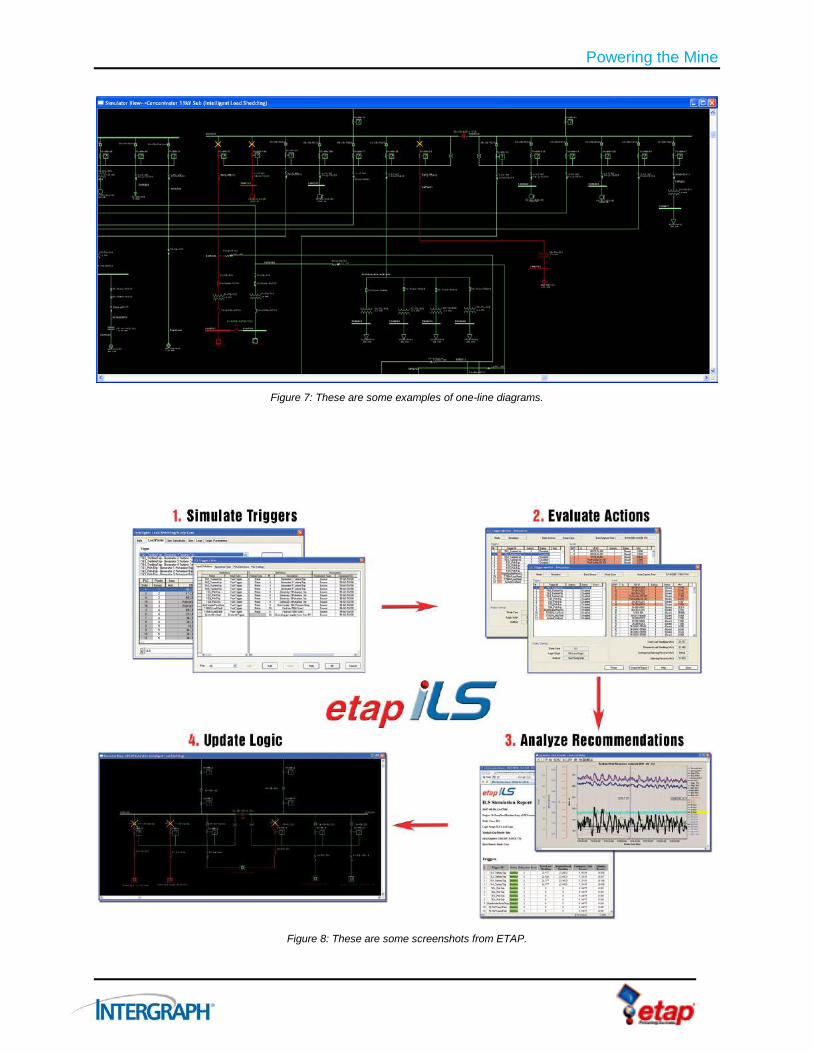
Figure 7: These are some examples of one-line diagrams.
Figure 8: These are some screenshots from ETAP.

Powering the Mine
17
Figure 9: These are some screenshots from ETAP.

Powering the Mine
18
8.5. Schematics After the design of the distribution network, SmartPlant Electrical enables you to take the next step in detailed design and create the schematics for the different loads with the interlocks from the control system.
SmartPlant Electrical offers the capability to create the schematics using templates based on best practices or the client’s standard requirements.
In addition, some schematics may come from the vendor and these can be used in conjunction with the documents created in SmartPlant Electrical to:
Avoid duplicated work.
Keep a complete set of schematics for the operational team.
Figure 10: SmartPlant Electrical uses standard and consistent schematic configurations.

Powering the Mine
19
8.6. Routing Cables We also need to consider the physical design activities, such as placing the equipment and panels. We need to route the cable in the shortest, most efficient path and in a manner that offers protection for the cables and ensures the right type of cable is applied. In most cases, a 3D model is used to design the trays, trenches, and conduits and to route the cables (see Figure 11).
The SmartPlant Electrical model is exported to SmartPlant 3D, where cable and equipment associations are made in the 3D model and cables are routed. The actual cable length is then transferred back to SmartPlant Electrical for size verification. Initial cable sizing is typically based on estimated lengths, but the actual lengths derived from 3D will allow this to be updated and then accurate cable schedules can be produced.
When all is routed and verified, SmartPlant Electrical also provides drum (reel) management. Cables are optimized on the drums with the set length and cutting plan to ensure no waste or shortage is created during construction.
Figure 11: SmartPlant Electrical helps you route cables in 3D. Here, the cable routes are highlighted in green.

Powering the Mine
20
8.7. Deliverables The market differentiator of the SmartPlant Electrical solution, and one of its most powerful features, is its ability to create deliverables automatically from a single data source. This provides consistency, facilitates change management, and produces a range of deliverables that fit the task.
Because the deliverables are a “view” of the data, you can create the deliverables in a format and with content that meet exact end-user needs. For example:
Purchasing department only needs component/cable data to place an order.
Contractor in the field laying the cables only needs the cable schedule and pull slips.
Termination crew only needs the termination schedule.
This greatly increases productivity from design to installation. It also avoids errors as a result of information being entered multiple times, increasing the chance of data entry error, or from the most relevant information not being available.
Documentation can also be created to commission and test the system before going online. Any changes made during this phase can be entered into the system to quickly populate an as-built design database in SmartPlant Electrical for handover to the operations team.
Figure 12: Cables are delivered to site ready to use.
Powering the Mine
21
8.8. Making the Changes Winston Churchill said, “To improve is to have to change, and to be perfect, you have to change often.”
Business is changing quickly due to tight competition, rapidly fluctuating market demands, and windows of opportunities that can close very quickly. To be successful, businesses must be able to adapt.
New solutions such as SmartPlant Electrical and its bidirectional link with ETAP will offer many possibilities for improved efficiency. These tools may demand changes in work processes and could possibly introduce changes to the type and format of deliverables. But these changes can provide significant advantages. Intergraph can help you take full advantage of these solutions to make the changes needed for increased productivity.
8.8.1. Concurrent Processes
The sample processes described in this white paper are sequential in nature and are intended as examples of typical design. In reality, this work is usually performed concurrently, and, of course, Intergraph solutions support concurrent processes. However, the examples in this white paper clearly present the solution’s main capabilities and how the solution can help meet your needs.

Powering the Mine
22
8.9. Operations Once the design is complete and the mine is ready to be powered and turned on, operations and maintenance begin. As mentioned in Section 3.1.1, owners are looking to optimize the maintenance process by moving to a thin maintenance model. SmartPlant Electrical is a perfect fit in this strategy. Its powerful electrical database provides all of the components, specifications, and connectivity required for a thin maintenance model.
It is now very easy to access the relevant data in context and to transform it into information that will support preventative and emergency maintenance. With the relationships in SmartPlant Electrical, you can select any plant item, like a motor, and then quickly gather all related information about that motor, such as:
Details about connected cables.
Information about the panel to which the motor is connected.
Any vendor documents.
Motor data sheets.
Correct decisions can be made quickly to reduce production interruptions and safety issues.
All of this can be done remotely and electronically. Instructions and data/documents can be sent to the plant site and made available on Web-based interfaces or even on handheld mobile devices and tablets.
Predictive simulation is used for onsite change requests, such as increased motor size, or new feeders and loads, which are used to analyze system impacts through the link to ETAP. Approved changes can then be made in the database and a complete set of new documents can be generated as reports.
If data is entered many times in multiple documents, there will always be errors and inconsistencies. The days of manually updating multiple drawings and documents to reflect changes are over. Now, because the data is entered only once and used many times, it can more easily be maintained as correct data.
ETAP intelligent load shedding provides the next logical step in optimal load shedding for electrical disturbances such as:
Faults.
Mechanical disturbances, such as turbine trips.
Demand side management.
ETAP provides faster execution of load shedding as compared to conventional systems. This further reduces the load relief requirements.
The solution supports your company’s key strategic initiatives to:
Remain competitive.
Lower the cost of operations.
Attract the right people.
Optimize productivity of the mine.

Powering the Mine
23
9. Business Benefits There are several products in the market that can generate electrical schematics, but that alone does not solve the fundamental problems faced by mining companies.
Owners are looking for solutions that can make a difference and support their overall business strategies. As previously mentioned, mining projects have many challenges, including:
High capital investments.
Remote locations.
Safety.
Human resource issues.
Government regulations.
Engineering solutions cannot solve all of these issues, but can make a significant contribution.
Additionally, the solution needs to meet operational requirements, because this is the longest and most costly part of the mine’s life cycle.
Intergraph SmartPlant Electrical working together with ETAP can help you achieve your business objectives by providing a unique solution for:
Engineering.
Design.
Validation of data.
Construction support.
Commissioning and operations.

Powering the Mine
24
10. Conclusion Moving from CAD and Excel-based design tools into a data-centric design environment requires a step change in thought and work practices.
Making a step change is easier said than done. But Intergraph offers a long and proven record of helping customers to be successful with its solutions, which are developed in close cooperation with industry leaders.
All of Intergraph Process, Power & Marine’s team members follow rule No. 1: “Never let a customer down.” Our team stands fully behind your business, which raises your confidence and lowers the risk of implementing changes to achieve your business goals.

Powering the Mine
25
11. References
11.1. Sinclair Knight Merz, Australia
11.1.1. SKM Selects Intergraph SmartPlant Enterprise, Including SmartPlant Electrical
Leading engineering and project delivery company uses next-generation technology to configure integrated capability for mining and metals projects
Sinclair Knight Merz (SKM), a global engineering and project delivery company, has chosen Intergraph SmartPlant Enterprise solutions to configure integrated engineering and project delivery capability for the mining and metals industry.
With its intelligent, rule-based technology and automation capabilities, the company determined that Intergraph’s next-generation SmartPlant Enterprise is the ideal match for its requirements and selected the integrated suite of SmartPlant Enterprise solutions, including SmartPlant Electrical, SmartPlant 3D Materials Handling Edition, SmartPlant Foundation, SmartPlant Instrumentation, SmartPlant Materials and SmartPlant P&ID.
Denis Hamel, global engineering manager at SKM, said, “We decided to expand our use of Intergraph solutions because we can leverage the advanced, next-generation technology of the integrated SmartPlant Enterprise suite for mining and metals projects, and optimize project delivery.”
Gerhard Sallinger, Intergraph Process, Power & Marine president, said, “SmartPlant Enterprise has been used successfully by the global leaders in the process, power and marine industries, and we are pleased to see SKM, one of the world’s leading engineering and project delivery firms in the mining sector, adopt SmartPlant Enterprise for its projects. The integration of SmartPlant Enterprise with SKM’s global delivery systems enhances its project delivery capability, and enables increased safety, quality and productivity of its mining projects.”
SmartPlant Enterprise offers a powerful portfolio of industry-leading, best-in-class design and data management solutions, enabling companies in the process, power and marine industries to capture integrated engineering knowledge at the enterprise level for the competitive advantage needed in today’s and tomorrow’s market. SmartPlant Enterprise’s integrated suite of solutions enables proven productivity gains, improving engineering efficiency by up to 30 percent. This is why the majority of plants built worldwide are designed using Intergraph solutions.

Powering the Mine
26
11.2. Lonmin Plc, South Africa
11.2.1. ETAP Power System Monitoring and Optimization Deployed by Lonmin Plc
Mining company uses ETAP PSMS for real-time monitoring and simulation capabilities, and ETAP Network Analysis for power system optimization
Applied Energy Solutions (Pty) Ltd, a leading-edge hardware and software supplier to utility, engineering, industrial and commercial markets, along with Operation Technology, Inc. developers of the ETAP enterprise solution for electrical power systems, has announced that Lonmin Plc has selected ETAP for the monitoring, simulation and optimization of its power systems. ETAP has been implemented at the company’s Western Platinum Mine in South Africa’s North West province.
Lonmin Plc has deployed ETAP Power System Monitoring & Simulation (PSMS) to monitor the entire power system. ETAP PSMS, an intelligent energy management application, offers such capabilities as advanced monitoring and real-time simulation. Lonmin Plc benefits from complete electrical monitoring of their electrical system.
In addition, Lonmin Plc is also using ETAP for a full spectrum of power system optimization features. Modules include Short-Circuit, Load Flow, Motor Acceleration, Optimal Power Flow, Cable Sizing & Ampacity, and more.
"Lonmin Plc is one of the leading platinum mining organizations in South Africa, and we believe it is ideally suited for the ETAP Real-Time approach to power system monitoring,” says Dr. Ian Boake, Managing Director of Applied Energy Solutions (Pty) Ltd. "Lonmin’s application of the ETAP solution will provide additional power system monitoring, simulation and optimization benefits to its business.”
“We have worked very closely with Lonmin Pc to develop a scalable platform to deliver real-time power system data to its highly experienced engineering team," says Tanuj Khandelwal, Principal Electrical Engineer and Regional Area Manager for South Africa. "We expect that this integrated approach will help enhance Lonmin's power system performance over time, and we look forward to continuing to support those efforts in the future."

Powering the Mine
27
11.3. PT Newmont Nusa Tenggara, Indonesia
11.3.1. PT Newmont Nusa Tenggara Uses the ETAP Enterprise Solution to Monitor, Control and Optimize Its Electrical Power Generation and Transmission
PT Newmont Nusa Tenggara (PTNNT), operator of one of Indonesia’s largest copper-gold mines deployed the ETAP Real-Time enterprise power system solution to reduce production losses due to faults caused by a variety of environmental disturbances. In addition, PTNNT is using ETAP Real-Time to monitor, control and optimize power generation and transmission at its facilities throughout Indonesia’s Sumbawa island.
PTNNT’s installation of ETAP Real-Time employs two primary products: ETAP Intelligent Load Shedding (ILS) and ETAP Power System Monitoring & Simulation (ETAP Real-Time). Together, these products provide PTNNT with a fully integrated system to optimize electrical power management, resulting in lower generation cost and fewer process time losses due to unnecessary load tripping.
The ETAP ILS system was put to the test in April 2006 when an event triggered the shutdown of several of the operation’s turbines. The shutdown amounted to 35 MW of generation dropped. Prior to the installation of ETAP ILS, the same circumstances would have prompted the system to shed over 50 MW of power, which would have brought the operation to a temporary stop. But ETAP ILS recognized the problem and shed 39 MW based on the current customer preferences, and operations remained stable, much to the satisfaction of PT Newmont senior executives. According to GF Power and T&D Maintenance Engineers at PTNNT, ETAP ILS is the most intelligent load shedding system available compared with any other products on the market.

Powering the Mine
28
11.3.2. ETAP Intelligent Load Shedding Deployed at One of Indonesia’s Largest Copper-Gold Mines
PT Newmont Nusa Tenggara uses the ETAP enterprise solution to monitor, control and optimize its electrical power generation and transmission
Operation Technology, Inc. (OTI) has announced that PT Newmont Nusa Tenggara (PTNNT), operator of one of Indonesia’s largest copper-gold mines, has successfully deployed the ETAP Real-Time enterprise power system solution to reduce production losses due to faults caused by a variety of environmental disturbances. In addition, PTNNT is using ETAP Real-Time to monitor, control and optimize power generation and transmission at its facilities throughout Indonesia’s Sumbawa island.
PTNNT’s installation of ETAP Real-Time employs two primary products: ETAP Intelligent Load Shedding (ILS) and ETAP Power System Monitoring & Simulation (PSMS). Together, these products provide PTNNT with a fully integrated system to optimize electrical power management, resulting in lower generation cost and fewer process time losses due to unnecessary load tripping.
For this project, the heart of ETAP Real-Time is ILS, an advanced product that uses artificial intelligence to dynamically determine the optimal system response to a variety of system changes and disturbances. ILS evaluates electrical and physical parameters, network topology, control logics and system operating conditions (loading, generation, etc.) to determine the best load shedding priority, based on the type and location of the disturbances.
ILS provides faster execution of load shedding, as compared to conventional frequency relays, further reducing the load relief requirements.
ETAP Real-Time, which has been operating at PTNNT for more than six months, was the ideal solution for the Indonesia-based company according to Ilyas Yamin, GF Power and T&D Maintenance for PTNNT. “ETAP ILS is the most intelligent load shedding system available compared with any other products on the market.”
The development of ILS was a defining milestone for OTI, stated Dr. Farrokh Shokooh, President and CEO of OTI. “We have developed many new state-of-the-art products in our 20-year history, but ETAP Intelligent Load Shedding stands out as one of our greatest achievements,” Shokooh adds. “ILS has broken new ground in electrical power management technology by providing the intelligence and speed required to minimize the detrimental effects of power system transients. We are extremely proud to see ETAP ILS in action.”

For more information about Intergraph, visit our website at www.intergraph.com.
©2013 Intergraph Corporation. All Rights Reserved. Intergraph is part of Hexagon. Intergraph and the Intergraph logo are registered trademarks of Intergraph Corporation or its subsidiaries in the United States and in other countries. Microsoft and Excel are registered trademarks of Microsoft Corp. Other brands and product names are trademarks of their respective owners. Intergraph believes that the information in this publication is accurate as of its publication date. Such information is subject to change without notice. Intergraph is not responsible for inadvertent errors. 05/13 PPM-US-0224A-ENG