powermax45 service manual
TRANSCRIPT

45Plasma arc cutting system
Service Manual – 806110Revision 2

Register your new Hypertherm system
Register your product online at www.hypertherm.com/registration for easier technical and warranty support. You can also receive updates on new Hypertherm products and a free gift as a token of our appreciation.
For your records
Serial number:________________________________________________________________
Purchase date: _______________________________________________________________
Distributor: __________________________________________________________________
____________________________________________________________________________
____________________________________________________________________________
Maintenance notes:
____________________________________________________________________________
____________________________________________________________________________
____________________________________________________________________________
____________________________________________________________________________
____________________________________________________________________________
____________________________________________________________________________
Service Manual
(P/N 806110)
Revision 2 – April, 2013
Hypertherm, Inc.Hanover, NH USA
www.hypertherm.com
© Copyright 2013 Hypertherm, Inc.All Rights Reserved
Hypertherm and powermax are trademarks of Hypertherm, Inc. and may be registered in the United States and/or other countries.
45

Hypertherm, Inc.Etna Road, P.O. Box 5010Hanover, NH 03755 USA603-643-3441 Tel (Main Office)603-643-5352 Fax (All Departments)[email protected] (Main Office Email)800-643-9878 Tel (Technical Service)[email protected] (Technical Service Email)800-737-2978 Tel (Customer Service)[email protected] (Customer Service Email)866-643-7711 Tel (Return Materials Authorization)877-371-2876 Fax (Return Materials Authorization)[email protected] (RMA email)
Hypertherm Plasmatechnik GmbHTechnologiepark HanauRodenbacher Chaussee 6 D-63457 Hanau-Wolfgang, Deutschland49 6181 58 2100 Tel49 6181 58 2134 Fax49 6181 58 2123 (Technical Service)
Hypertherm (S) Pte Ltd.82 Genting LaneMedia CentreAnnexe Block #A01-01Singapore 349567, Republic of Singapore65 6841 2489 Tel65 6841 2490 Fax 65 6841 2489 (Technical Service)
Hypertherm (Shanghai) Trading Co., Ltd.Unit 301, South Building 495 ShangZhong RoadShanghai, 200231PR China86-21-60740003 Tel86-21-60740393 Fax
Hypertherm Europe B.V.Vaartveld 94704 SE Roosendaal, Nederland31 165 596907 Tel31 165 596901 Fax31 165 596908 Tel (Marketing)31 165 596900 Tel (Technical Service)00 800 4973 7843 Tel (Technical Service)
Hypertherm Japan Ltd.Level 9, Edobori Center Building2-1-1 Edobori, Nishi-kuOsaka 550-0002 Japan81 6 6225 1183 Tel81 6 6225 1184 Fax
Hypertherm Brasil Ltda.Rua Bras Cubas, 231 – Jardim MaiaGuarulhos, SP - BrasilCEP 07115-03055 11 2409 2636 Tel55 11 2408 0462 Fax
Hypertherm México, S.A. de C.V.Avenida Toluca No. 444, Anexo 1,Colonia Olivar de los PadresDelegación Álvaro ObregónMéxico, D.F. C.P. 0178052 55 5681 8109 Tel52 55 5683 2127 Fax
Hypertherm Korea Branch#3904 Centum Leaders Mark B/D,1514 Woo-dong, Haeundae-gu, BusanKorea, 612-88982 51 747 0358 Tel82 51 701 0358 Fax
07/18/12

Safety informationBefore operating any Hypertherm equipment, read the separate Safety and Compliance Manual (80669C) included with your product for important safety information.

TAble of CoNTeNTS
powermax45 Service Manual i
TAble of CoNTeNTS
eleCTRoMAgNeTIC CoMPATIbIlITy (eMC) .......................................................................................................eMC-1
WARRANTy ............................................................................................................................................................................W-1
SeCTIoN 1
SPeCIfICATIoNS
System description ....................................................................................................................................................................................1-2Where to find information ........................................................................................................................................................................1-2Power supply dimensions and weights ................................................................................................................................................1-3
Dimensions .......................................................................................................................................................................................1-3Weights .............................................................................................................................................................................................1-3
Power supply ratings .................................................................................................................................................................................1-4T45v torch dimensions .............................................................................................................................................................................1-5T45m torch dimensions ............................................................................................................................................................................1-5T45v and T45m torch specifications .....................................................................................................................................................1-6Symbols and marks ...................................................................................................................................................................................1-7IEC symbols ................................................................................................................................................................................................1-8
SeCTIoN 2
PoWeR SUPPly SeTUP
Unpack the Powermax45 .........................................................................................................................................................................2-2Claims ................................................................................................................................................................................................2-2Contents ............................................................................................................................................................................................2-2
Position the power supply........................................................................................................................................................................2-3Prepare the electrical power ...................................................................................................................................................................2-3
Voltage configurations ....................................................................................................................................................................2-3Install a line-disconnect switch ....................................................................................................................................................2-4Requirements for grounding .........................................................................................................................................................2-4

Table of ConTenTs
ii powermax45 Service Manual
Power cord considerations ......................................................................................................................................................................2-4Extension cord recommendations ...............................................................................................................................................2-5Generator recommendations ........................................................................................................................................................2-6
Prepare the gas supply .............................................................................................................................................................................2-6Connect the gas supply .................................................................................................................................................................2-7Additional gas filtration ...................................................................................................................................................................2-7
SeCTIoN 3
ToRCH SeTUP
Introduction .................................................................................................................................................................................................3-2Consumable life ..........................................................................................................................................................................................3-2Hand torch setup .......................................................................................................................................................................................3-2
Choose the consumables ..............................................................................................................................................................3-3Install the consumables ..................................................................................................................................................................3-5
Machine torch setup..................................................................................................................................................................................3-6Mount the torch ................................................................................................................................................................................3-6Choose the consumables (cut charts) .......................................................................................................................................3-8Using the cut charts ........................................................................................................................................................................3-8T45m shielded consumables ........................................................................................................................................................3-8Align the torch ...............................................................................................................................................................................3-24Connect the remote-start pendant ...........................................................................................................................................3-25Connect a machine interface cable .........................................................................................................................................3-25Accessing raw arc voltage .........................................................................................................................................................3-27
Connect the torch lead ..........................................................................................................................................................................3-30
SeCTIoN 4
oPeRATIoN
Controls and indicators ............................................................................................................................................................................4-2Front controls and LEDs ................................................................................................................................................................4-2Rear controls ....................................................................................................................................................................................4-3
Operate the Powermax45 ........................................................................................................................................................................4-3Connect the electrical power and gas supply ..........................................................................................................................4-3Power ON the system ....................................................................................................................................................................4-4Set the mode switch .......................................................................................................................................................................4-4Adjust the gas pressure .................................................................................................................................................................4-4Check the indicator LEDs .............................................................................................................................................................4-6Attach the work clamp ...................................................................................................................................................................4-6
Understand duty-cycle limitations ..........................................................................................................................................................4-6How to use the hand torch ......................................................................................................................................................................4-7
Operate the safety trigger .............................................................................................................................................................4-7Hand torch cutting hints ................................................................................................................................................................4-7Start a cut from the edge of the workpiece...............................................................................................................................4-8

Table of ConTenTs
powermax45 Service Manual iii
Pierce a workpiece ..........................................................................................................................................................................4-9Gouge a workpiece .....................................................................................................................................................................4-10Common hand-cutting faults .....................................................................................................................................................4-12
How to use the machine torch .............................................................................................................................................................4-12Ensure the torch and table are set up correctly ....................................................................................................................4-12Understand and optimize cut quality ........................................................................................................................................4-13To pierce a workpiece using the machine torch ...................................................................................................................4-14Common machine-cutting faults ...............................................................................................................................................4-15
SeCTIoN 5
TRoUbleSHooTINg ANd SySTeM TeSTS
Theory of operation ....................................................................................................................................................................................5-2General ..............................................................................................................................................................................................5-2200–240 V CSA and 230 V CE 1-phase power supply functional description..............................................................5-2400 V CE 3-phase power supply functional description .......................................................................................................5-2480 V CSA 3-phase power supply functional description ....................................................................................................5-3Sequence of operation ...................................................................................................................................................................5-4
Troubleshooting preparation ...................................................................................................................................................................5-5Test equipment ................................................................................................................................................................................5-5Troubleshooting procedures and sequence .............................................................................................................................5-5External inspection ..........................................................................................................................................................................5-6Internal inspection ...........................................................................................................................................................................5-6
Initial resistance check ..............................................................................................................................................................................5-7200–240 V CSA and 230 V CE power supply overview ................................................................................................................5-8400 V CE power supply overview .........................................................................................................................................................5-9480 V CSA power supply overview ...................................................................................................................................................5-10Troubleshooting guide ...........................................................................................................................................................................5-11Control Board LEDs ...............................................................................................................................................................................5-16
Use the control board Error and Reset LEDs to troubleshoot ...........................................................................................5-17System tests.............................................................................................................................................................................................5-18
Test 1 – voltage input ..................................................................................................................................................................5-18Test 2 – power board voltage checks .....................................................................................................................................5-19Test 3 – VBUS and voltage balance .......................................................................................................................................5-20Test 4 – solenoid valve ...............................................................................................................................................................5-24Test 5 – torch stuck open (TSO) or torch stuck closed (TSC) ........................................................................................5-25Test 6 – plasma start ...................................................................................................................................................................5-26Test 7 – torch cap sensor ..........................................................................................................................................................5-27Test 8 – fan ....................................................................................................................................................................................5-27Test 9 – pressure transducer ....................................................................................................................................................5-28Test 10 – power switch trip coil ...............................................................................................................................................5-28
Table of ConTenTs
iv powermax45 Service Manual
SeCTIoN 6
CoMPoNeNT RePlACeMeNT
Remove and replace the cover and Mylar® barrier .............................................................................................................................6-2Removal .............................................................................................................................................................................................6-2Replacement .....................................................................................................................................................................................6-3
Replace the work lead (CSA and CE) ..................................................................................................................................................6-3Replace the power cord (200–240 V CSA) .......................................................................................................................................6-5Replace the power cord (230 V CE) ....................................................................................................................................................6-6Replace the power cord (400 V CE) ....................................................................................................................................................6-8Replace the power cord (480 V CSA) ..............................................................................................................................................6-10Replace the fan .......................................................................................................................................................................................6-12Replace the gas filter element .............................................................................................................................................................6-13Replace the air filter and regulator ......................................................................................................................................................6-15Replace the control board ....................................................................................................................................................................6-16Replace the power board (200–240 V CSA and 230 V CE) ......................................................................................................6-17Replace the power board (400 V CE and 480 V CSA) ................................................................................................................6-21
SeCTIoN 7
PARTS
Power supply parts ....................................................................................................................................................................................7-2Exterior ...............................................................................................................................................................................................7-2Interior, power board side .............................................................................................................................................................7-4Interior, fan side ...............................................................................................................................................................................7-5Interior, heat sink side .....................................................................................................................................................................7-6
T45v hand torch parts...............................................................................................................................................................................7-7T45v hand torch consumables .....................................................................................................................................................7-8T30v (Powermax30) 30 A consumables ...................................................................................................................................7-8
T45m machine torch parts .......................................................................................................................................................................7-9T45m machine torch consumables ..........................................................................................................................................7-10
Accessory parts.......................................................................................................................................................................................7-10Safety-critical parts.................................................................................................................................................................................7-11Recommended spare parts ..................................................................................................................................................................7-12Powermax45 labels ................................................................................................................................................................................7-13
SeCTIoN 8
WIRINg dIAgRAMS
Control board diagram: 200–240 V CSA and 230 V CE ...............................................................................................................8-2Control board diagram: 400 V CE and 480 V CSA ..........................................................................................................................8-3Power board wiring diagram: 200–240 V CSA and 230 V CE .....................................................................................................8-5Power board wiring diagram: 400 V CE ..............................................................................................................................................8-6Power board wiring diagram: 480 V CSA ...........................................................................................................................................8-7
Compliance Information eMC-1
7/10
eleCTRoMAgNeTIC CoMPATIbIlITy (eMC)
IntroductionHypertherm’s CE-marked equipment is built in compliance with standard EN60974-10. The equipment should be installed and used in accordance with the information below to achieve electromagnetic compatibility.
The limits required by EN60974-10 may not be adequate to completely eliminate interference when the affected equipment is in close proximity or has a high degree of sensitivity. In such cases it may be necessary to use other measures to further reduce interference.
This cutting equipment is designed for use only in an industrial environment.
Installation and useThe user is responsible for installing and using the plasma equipment according to the manufacturer’s instructions.
If electromagnetic disturbances are detected then it shall be the responsibility of the user to resolve the situation with the technical assistance of the manufacturer. In some cases this remedial action may be as simple as earthing the cutting circuit, see Earthing of the work piece. In other cases, it could involve constructing an electromagnetic screen enclosing the power source and the work complete with associated input filters. In all cases, electromagnetic disturbances must be reduced to the point where they are no longer troublesome.
Assessment of areaBefore installing the equipment, the user shall make an assessment of potential electromagnetic problems in the surrounding area. The following shall be taken into account:
a. Other supply cables, control cables, signaling and telephone cables; above, below and adjacent to the cutting equipment.
b. Radio and television transmitters and receivers.
c. Computer and other control equipment.
d. Safety critical equipment, for example guarding of industrial equipment.
e. Health of the people around, for example the use of pacemakers and hearing aids.
f. Equipment used for calibration or measurement.
g. Immunity of other equipment in the environment. User shall ensure that other equipment being used in the environment is compatible. This may require additional protection measures.
h. Time of day that cutting or other activities are to be carried out.
The size of the surrounding area to be considered will depend on the structure of the building and other activities that are taking place. The surrounding area may extend beyond the boundaries of the premises.
Methods of reducing emissionsMains supplyCutting equipment must be connected to the mains supply according to the manufacturer’s recommendations. If interference occurs, it may be necessary to take additional precautions such as filtering of the mains supply.
eMC-2 Compliance Information
7/10
ELECTROMAGNETIC COMPATIBILITY
Consideration should be given to shielding the supply cable of permanently installed cutting equipment, in metallic conduit or equivalent. Shielding should be electrically continuous throughout its length. The shielding should be connected to the cutting mains supply so that good electrical contact is maintained between the conduit and the cutting power source enclosure.
Maintenance of cutting equipmentThe cutting equipment must be routinely maintained according to the manufacturer’s recommendations. All access and service doors and covers should be closed and properly fastened when the cutting equipment is in operation. The cutting equipment should not be modified in any way, except as set forth in and in accordance with the manufacturer’s written instructions. For example, the spark gaps of arc striking and stabilizing devices should be adjusted and maintained according to the manufacturer’s recommendations.
Cutting cablesThe cutting cables should be kept as short as possible and should be positioned close together, running at or close to the floor level.
equipotential bondingBonding of all metallic components in the cutting installation and adjacent to it should be considered.
However, metallic components bonded to the workpiece will increase the risk that the operator could receive a shock by touching these metallic components and the electrode (nozzle for laser heads) at the same time.
The operator should be insulated from all such bonded metallic components.
earthing of the workpieceWhere the workpiece is not bonded to earth for electrical safety, nor connected to earth because of its size and position, for example, ship’s hull or building steel work, a connection bonding the workpiece to earth may reduce emissions in some, but not all instances. Care should be taken to prevent the earthing of the workpiece increasing the risk of injury to users, or damage to other electrical equipment. Where necessary, the connection of the workpiece to earth should be made by a direct connection to the workpiece, but in some countries where direct connection is not permitted, the bonding should be achieved by suitable capacitances selected according to national regulations.
Note: The cutting circuit may or may not be earthed for safety reasons. Changing the earthing arrangements should only be authorized by a person who is competent to assess whether the changes will in crease the risk of injury, for example, by allowing parallel cutting current return paths which may damage the earth circuits of other equipment. Further guidance is provided in IEC 60974-9, Arc Welding Equip ment, Part 9: Installation and Use.
Screening and shieldingSelective screening and shielding of other cables and equipment in the surrounding area may alleviate problems of interference. Screening of the entire plasma cutting installation may be considered for special applications.

Compliance Information W-1
9/10
AttentionGenuine Hypertherm parts are the factory-recommended replacement parts for your Hypertherm system. Any damage or injury caused by the use of other than genuine Hypertherm parts may not be covered by the Hypertherm warranty, and will constitute misuse of the Hypertherm Product.
You are solely responsible for the safe use of the Product. Hypertherm does not and cannot make any guarantee or warranty regarding the safe use of the product in your environment.
generalHypertherm, Inc. warrants that its Products shall be free from defects in materials and workmanship for the specific periods of time set forth herein and as follows: if Hypertherm is notified of a defect (i) with respect to the plasma power supply within a period of two (2) years from the date of its delivery to you, with the exception of Powermax brand power supplies, which shall be within a period of three (3) years from the date of delivery to you, and (ii) with respect to the torch and leads within a period of one (1) year from its date of delivery to you, and with respect to torch lifter assemblies within a period of one (1) year from its date of delivery to you, and with respect to Automation products one (1) year from its date of delivery to you, with the exception of the EDGE Pro CNC and ArcGlide THC, which shall be within a period of two (2) years from the date of delivery to you, and (iii) with respect to HyIntensity fiber laser components within a period of two (2) years from the date of its delivery to you, with the exception of laser heads and beam delivery cables, which shall be within a period of one (1) year from its date of delivery to you.
This warranty shall not apply to any Powermax brand power supplies that have been used with phase converters. In addition, Hypertherm does not warranty systems that have been damaged as a result of poor power quality, whether from phase converters or incoming line power. This warranty shall not apply to any product which has been incorrectly installed, modified, or otherwise damaged.
Hypertherm provides repair, replacement or adjustment of the Product as the sole and exclusive remedy, if and only if the warranty set forth herein properly is invoked and applies. Hypertherm, at its sole option, shall repair, replace, or adjust, free of charge, any defective Products covered by this warranty which shall be returned with Hypertherm’s prior authorization (which shall not be unreasonably withheld), properly packed, to Hypertherm’s place of business in Hanover, New Hampshire, or to an authorized Hypertherm repair facility, all costs, insurance and freight pre paid by the customer. Hypertherm shall not be liable for any repairs, replacement, or adjustments of Products covered by this warranty, except those made pursuant to this paragraph and with Hypertherm’s prior written consent.
The warranty set forth above is exclusive and is in lieu of all other warranties, express, implied, statutory, or otherwise with respect to the Products or as to the results which may be obtained therefrom, and all implied warranties or conditions of quality or of merchantability or fitness for a particular purpose or against infringement. The foregoing shall constitute the sole and exclusive remedy for any breach by Hypertherm of its warranty.
Distributors/OEMs may offer different or additional warranties, but Distributors/OEMs are not authorized to give any additional warranty protection to you or make any representation to you purporting to be binding upon Hypertherm.
WARRANTy

W-2 Compliance Information
9/10
WARRANTY
Patent indemnityExcept only in cases of products not manufactured by Hypertherm or manufactured by a person other than Hypertherm not in strict conformity with Hypertherm’s specifications and in cases of designs, processes, formulae, or combinations not developed or purported to be developed by Hypertherm, Hypertherm will have the right to defend or settle, at its own expense, any suit or proceeding brought against you alleging that the use of the Hypertherm product, alone and not in combination with any other product not supplied by Hypertherm, infringes any patent of any third party. You shall notify Hypertherm promptly upon learning of any action or threatened action in connection with any such alleged infringement (and in any event no longer than fourteen (14) days after learning of any action or threat of action), and Hypertherm’s obligation to defend shall be conditioned upon Hypertherm’s sole control of, and the indemnified party’s cooperation and assistance in, the defense of the claim.
limitation of liabilityIn no event shall Hypertherm be liable to any person or entity for any incidental, consequential direct, indirect, punitive or exemplary damages (including but not limited to lost profits) regardless of whether such liability is based on breach of contract, tort, strict liability, breach of warranty, failure of essential purpose, or otherwise, and even if advised of the possibility of such damages.
National and local codesNational and local codes governing plumbing and electrical installation shall take precedence over any instructions contained in this manual. In no event shall Hypertherm be liable for injury to persons or property damage by reason of any code violation or poor work practices.
liability capIn no event shall Hypertherm’s liability, if any, whether such liability is based on breach of contract, tort, strict liability, breach of warranties, failure of essential purpose or otherwise, for any claim, action, suit or proceeding (whether in court, arbitration, regulatory proceeding or otherwise) arising out of or relating to the use of the Products exceed in the aggregate the amount paid for the Products that gave rise to such claim.
InsuranceAt all times you will have and maintain insurance in such quantities and types, and with coverage sufficient and appropriate to defend and to hold Hypertherm harmless in the event of any cause of action arising from the use of the products.
Transfer of rightsYou may transfer any remaining rights you may have hereunder only in connection with the sale of all or substantially all of your assets or capital stock to a successor in interest who agrees to be bound by all of the terms and conditions of this Warranty. Within thirty (30) days before any such transfer occurs, you agree to notify in writing Hypertherm, which reserves the right of approval. Should you fail timely to notify Hypertherm and seek its approval as set forth herein, the Warranty set forth herein shall be null and void and you will have no further recourse against Hypertherm under the Warranty or otherwise.

powermax45 Service Manual 1-1
Section 1
SPeCIfICATIoNS
In this section:
System description ....................................................................................................................................................................................1-2Where to find information ........................................................................................................................................................................1-2Power supply dimensions and weights ................................................................................................................................................1-3
Dimensions .......................................................................................................................................................................................1-3Weights .............................................................................................................................................................................................1-3
Power supply ratings .................................................................................................................................................................................1-4T45v torch dimensions .............................................................................................................................................................................1-5T45m torch dimensions ............................................................................................................................................................................1-5T45v and T45m torch specifications .....................................................................................................................................................1-6Symbols and marks ...................................................................................................................................................................................1-7IEC symbols ................................................................................................................................................................................................1-8

SpecificationS
1-2 powermax45 Service Manual
System descriptionThe Powermax45 is a highly portable, 45-amp, handheld and mechanized plasma cutting system appropriate for a wide range of applications. The Powermax45 uses air or nitrogen to cut electrically conductive metals, such as mild or stainless steel or aluminum. With it, you can cut thicknesses up to 25.4 mm (1 inch) and pierce thicknesses up to 9.5 mm (3/8 inch).
The standard Powermax45 includes one complete set of the consumables needed for cutting (shield, retaining cap, swirl ring, nozzle, electrode), 2 spare electrodes, 2 spare nozzles, gouging consumables (handheld configurations only), a quick-disconnect air fitting (1/4 NPT on CSA units and 1/4 NPT x G-1/4 BSPP on CE units), a consumables box, a shoulder strap, an Operator Manual, a Quick Setup Card, and a Setup DVD. Mechanized configurations include a remote-start pendant as well.
You can order additional consumables and accessories – such as the plasma cutting guide – from any Hypertherm distributor. See the Parts section for a list of spare and optional parts.
The power cords on the 200–240 V CSA power supplies are shipped with a 50 A, 250 V plug (NEMA 6-50P) on the power cord. The CE units and the 480 V CSA units are shipped without a plug on the power cord. See Prepare the electrical power in the Power Supply Setup section for more information.
Where to find informationSystem specifications, such as size, weight, detailed electrical specifications, and cut speeds can be found in this section. For information on:
• Safety information – see the Safety and Compliance Manual for detailed safety information.
• Setup requirements, including power requirements, grounding, power cord configurations, extension cord requirements, and generator recommendations – see the Power Supply Setup section.
• Handheld and machine torch consumables, cut charts, and torch setup information – see the Torch Setup section.
• Information about the controls and LEDs, steps for system operation, and hints for improving cut quality – see the Operation section.
• Troubleshooting – see the Troubleshooting and System Tests section.
• Maintenance and repair instructions – see the Component Replacement section.
• Part numbers and ordering information for accessories, consumables, and replacement parts – see the Parts section.
• Wiring and timing diagrams – see the Wiring Diagrams section.
SpecificationS
powermax45 Service Manual 1-3
Power supply dimensions and weights
dimensions
Weights
Power supply weights given below include the hand torch with 6.1 m (20 foot) lead, a 6.1 m (20 foot) work lead, and a 3 m (10 foot) power cord.
• CSA 200–240 V power supply: 16.8 kg (37 pounds)
• CSA 480 V power supply: 15.9 kg (35 pounds)
• CE 230 V power supply: 16.6 kg (36.5 pounds)
• CE 400 V power supply: 15.9 kg (35 pounds)
34.8 cm(13.7 in)
31 cm(12.19 in)
42.6 cm(16.75 in)
17.2 cm(6.75 in)

SpecificationS
1-4 powermax45 Service Manual
Power supply ratings
Rated open-circuit voltage (U0)
CSA/CE, single-phaseCE, 3-phaseCSA, 3-phase
275 VDC (CSA/CE single-phase)275 VDC (CE 3-phase)
278 VDC (CSA 3-phase)
Rated output current (I2) 20 A to 45 A
Rated output voltage (U2) 132 VDC
Duty cycle at 40° C
(See data plate on power supply for more information on duty cycle.)
50% (I2=45 A, U2=132 V)60% (I2=41 A, U2=132 V)
100% (I2=32 A, U2=132 V)
Operating temperature -10° to 40° C (14° to 104° F)
Storage temperature -25° to 55° C (-13° to 131° F)
Power factor
200–240 V CSA, 230 V CE, 1-phase400 V CE, 3-phase480 V CSA, 3-phase
0.990.940.93
Input voltage (U1) / Input current (I1) at rated output (U2 MAX, I2 MAX)
(See Voltage configurations in the Power Supply Setup section for more information.)
200–240 VAC / 34–28 A (200–240 V CSA)230 VAC / 30 A (230 V CE)*400 VAC / 10 A (400 V CE)**480 VAC / 8.5 A (480 V CSA)
Gas type Air Nitrogen
Gas quality Clean, dry, oil-free per ISO 8573-1 Class 1.2.2
99.995% pure
Recommended gas inlet flow and pressure 170 l/min at 6.2 bar (360 scfh at 90 psi)
* Equipment complies with IEC 61000-3-12.
** Equipment complies with IEC 61000-3-12 provided that the short-circuit power Ssc is greater than or equal to 692 KVA at the interface point between the user’s supply and the public system. It is the responsibility of the installer or user of the equipment to ensure, by consultation with the distribution network operator if necessary, that the equipment is connected only to a supply with a short-circuit power Ssc greater than or equal to 692 KVA.

SpecificationS
powermax45 Service Manual 1-5
T45v torch dimensions
T45m torch dimensions
22.1 cm (8.72 in)21.6 cm (8.5 in)
8.3 cm(3.28 in)
4.0 cm(1.58 in)
2.5 cm(1 in)
4.9 cm (1.91 in)
36.5 cm(14.36 in)
(30.5 cm)12 in2.5 cm
(1 in)3.6 cm (1.43 in) outer dimension,
3.3 cm (1.3 in) flat sides
33.0 cm(13 in)
SpecificationS
1-6 powermax45 Service Manual
T45v and T45m torch specifications
Handheld cut capacity (material thickness)
Recommended cut capacity (hand cutting) 12.7 mm (1/2 inch)
Maximum cut capacity (hand cutting or mechanized edge start) 19.1 mm (3/4 inch)
Severance capacity (hand cutting or mechanized edge start) 25.4 mm (1 inch)
Mechanized pierce capacity (material thickness)
Pierce capacity(for edge starts, the capacities are the same as the handheld capacities)
9.5 mm (3/8 inch)
Recommended cut speed (on mild steel)6.35 mm (1/4 inch) 1524 mm/min (60 ipm)
9.53 mm (3/8 inch) 813 mm/min (32 ipm)
12.7 mm (1/2 inch) 508 mm/min (20 ipm)
19.1 mm (3/4 inch) 203 mm/min (8 ipm)
25.4 mm (1 inch) 102 mm/min (4 ipm)
gouging capacity
Metal removal rate on mild steel 2.8 kg/hr (6.2 lbs/hr)
WeightT45v torch only 0.27 kg (0.6 lb)
T45v with 6.1 m (20 foot) lead 1.55 kg (3.4 lb)
T45v with 15.24 m (50 foot) lead 3.54 kg (7.8 lb)
T45m torch only 0.45 kg (1.0 lb)
T45m with 7.62 m (25 foot) lead 2.27 kg (5.0 lb)
T45m with 10.7 m (35 foot) lead 2.90 kg (6.4 lb)
T45m with 15.24 m (50 foot) lead 3.85 kg (8.5 lb)

SpecificationS
powermax45 Service Manual 1-7
Symbols and marks
Your Hypertherm product may have one or more of the following markings on or near the data plate. Due to differences and conflicts in national regulations, not all marks are applied to every version of a product.
S mark symbolThe S mark symbol indicates that the power supply and torch are suit able for operations carried out in environments with in creased hazard of elec tri cal shock per IEC 60974-1.
CSA markHypertherm products with a CSA mark meet the United States and Canadian regulations for product safety. The products were evaluated, tested, and certified by CSA-International. Alternatively the product may have a mark by one of the other Nationally Recognized Testing Laboratories (NRTL) accredited in both the United States and Canada, such as Underwriters Laboratories, Incorporated (UL) or TÜV.
Ce marking The CE marking signifies the manufacturer’s declaration of conformity to applicable European directives and standards. Only those versions of Hypertherm products with a CE marking located on or near the data plate have been tested for compliance with the European Low Voltage Directive and the European Electromagnetic Compatibility (EMC) Directive. EMC filters needed to comply with the European EMC Directive are incorporated within versions of the product with a CE marking.
goST-TR markCE versions of Hypertherm products that include a GOST-TR mark of conformity meet the product safety and EMC requirements for export to the Russian Federation.
C-Tick mark CE versions of Hypertherm products with a C-Tick mark comply with the EMC regulations required for sale in Australia and New Zealand.
CCC markThe China Compulsory Certification (CCC) mark indicates that the product has been tested and found compliant with product safety regulations required for sale in China.
UkrSePRo markCE versions of Hypertherm products that include a UkrSEPRO mark of conformity meet the product safety and EMC requirements for export to the Ukraine.
SpecificationS
1-8 powermax45 Service Manual
IeC symbolsThe following symbols may appear on the power supply data plate, control labels, switches, and LEDs.
Direct current (DC)
Alternating current (AC)
Plasma torch cutting
Plate metal cutting
Expanded metal cutting
Gouging
AC input power connection
The terminal for the external protective (earth) conductor
Gas test mode
l Power is ON
o Power is OFF
An inverter-based power source, either 1-phase or 3-phase
Volt/amp curve, “drooping” characteristic
AC Power is ON (LED)
System fault (LED)
Inlet gas pressure fault (LED)
Missing or loose consumables (LED)
Power supply is out of temperature range (LED)
f1 f21~

powermax45 Service Manual 2-1
Section 2
PoWeR SUPPly SeTUP
In this section:
Unpack the Powermax45 .........................................................................................................................................................................2-2Claims ................................................................................................................................................................................................2-2Contents ............................................................................................................................................................................................2-2
Position the power supply........................................................................................................................................................................2-3Prepare the electrical power ...................................................................................................................................................................2-3
Voltage configurations ....................................................................................................................................................................2-3Install a line-disconnect switch ....................................................................................................................................................2-4Requirements for grounding .........................................................................................................................................................2-4
Power cord considerations ......................................................................................................................................................................2-4Extension cord recommendations ...............................................................................................................................................2-5Generator recommendations ........................................................................................................................................................2-6
Prepare the gas supply .............................................................................................................................................................................2-6Connect the gas supply .................................................................................................................................................................2-7Additional gas filtration ...................................................................................................................................................................2-7
Power suPPly setuP
2-2 powermax45 Service Manual
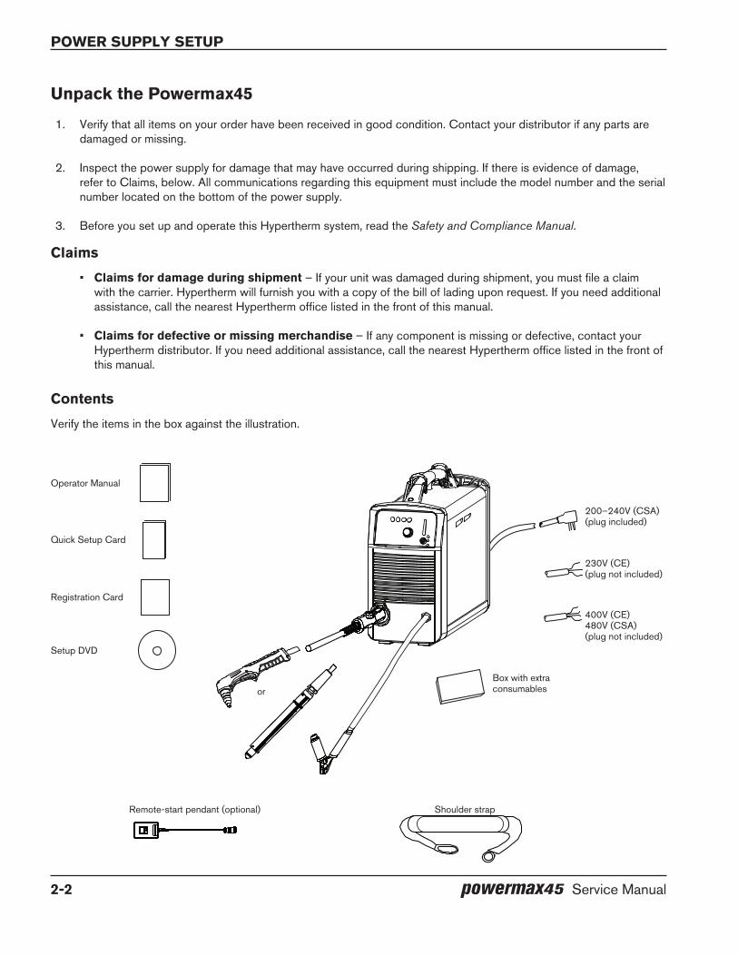
Operator Manual
Quick Setup Card
Registration Card
200–240V (CSA)(plug included)
Box with extra consumables
Setup DVD
or
Remote-start pendant (optional) Shoulder strap
Unpack the Powermax45
1. Verify that all items on your order have been received in good condition. Contact your distributor if any parts are damaged or missing.
2. Inspect the power supply for damage that may have occurred during shipping. If there is evidence of damage, refer to Claims, below. All communications regarding this equipment must include the model number and the serial number located on the bottom of the power supply.
3. Before you set up and operate this Hypertherm system, read the Safety and Compliance Manual.
Claims
• Claims for damage during shipment – If your unit was damaged during shipment, you must file a claim with the carrier. Hypertherm will furnish you with a copy of the bill of lading upon request. If you need additional assistance, call the nearest Hypertherm office listed in the front of this manual.
• Claims for defective or missing merchandise – If any component is missing or defective, contact your Hypertherm distributor. If you need additional assistance, call the nearest Hypertherm office listed in the front of this manual.
Contents
Verify the items in the box against the illustration.
230V (CE)(plug not included)
400V (CE)480V (CSA)(plug not included)

power supply setup
powermax45 Service Manual 2-3
Position the power supplyLocate the Powermax45 near an appropriate 200–240 volt power receptacle for CSA or CE 1-phase power supplies, a 400 volt receptacle for 3-phase CE power supplies, or a 480 volt receptacle for 3-phase CSA power supplies. The Powermax45 has a 3 m (10-foot) power cord. Allow at least 0.25 m (10 inches) of space around the power supply for proper ventilation.
Prepare the electrical powerThe maximum output voltage will vary based on your input voltage and the circuit’s amperage. Because the current draw varies during startup, slow-blow fuses are recommended as shown in the following chart. Slow-blow fuses can withstand currents up to 10 times the rated value for short periods of time.
Voltage configurations
The following chart shows the maximum rated output for typical combinations of input voltage and amperage. Acceptable input voltages can be ±10% of the values given below.
CAUTIoN
Protect the circuit with appropriately sized time-delay (slow-blow) fuses and a line-disconnect switch.
Model Input voltage Phase Rated outputInput
current at 6 kw output
Input current
during arc stretch
Recommended slow-blow fuse
size
CSA
200–240 VAC 1 45 A, 132 V 34–28 A 55–45 A 50 A
208 VAC 1 45 A, 132 V 33 A 54.5 A 50 A
480 VAC 3 45 A, 132 V 8.5 A 12 A 15 or 20* A
CE 200–240 VAC 1 45 A, 132 V 34–28 A 55–45 A 35 or 50* A
400 VAC 3 45 A, 132 V 10 A 15.5 A 15 or 20* A
CE/CCC220 VAC 1 45 A, 132 V 31 A 53 A 35 or 50* A
380 VAC 3 45 A, 132 V 11 A 14 A 15 A
* Use the higher amperage fuse for applications that require a long arc stretch.
Power suPPly setuP
2-4 powermax45 Service Manual
Install a line-disconnect switch
Use a line-disconnect switch for each power supply so that the operator can turn off the incoming power quickly in an emergency. Locate the switch so that it is easily accessible to the operator. Installation must be performed by a licensed electrician according to national and local codes. The interrupt level of the switch must be equal to or exceed the continuous rating of the fuses. In addition, the switch should:
• Isolate the electrical equipment and disconnect all live conductors from the incoming supply voltage when in the OFF position.
• Have one OFF and one ON position that are clearly marked with O (OFF) and I (ON).
• Have an external operating handle that can be locked in the OFF position.
• Contain a power-operated mechanism that serves as an emergency stop.
• Have slow-blow fuses installed as recommended in the table on the previous page.
Requirements for grounding
To ensure personal safety, proper operation, and to reduce electromagnetic interference (EMI), the Powermax45 must be properly grounded:
• The power supply must be grounded through the power cord according to national and local electrical codes.
• Single-phase service must be of the 3-wire type with a green or green/yellow wire for the protective earth ground and must comply with national and local requirements. do not use a 2-wire service.
• Three-phase service must be of the 4-wire type with a green or green/yellow wire for the protective earth ground and must comply with national and local requirements.
• Refer to the Safety and Compliance Manual for more information.
Power cord considerationsPowermax45 power supplies are shipped with CSA and CE power cord configurations.
The power cords on the 200–240 V CSA power supplies are shipped with a 50 amp, 250 V plug (NEMA 6-50P) on the power cord.
The CE power supplies and the 480 V CSA power supplies are shipped without a plug on the power cord. Obtain the correct plug for your unit (230 V CE, 400 V CE, or 480 V CSA) and location and have it installed by a licensed electrician.

power supply setup
powermax45 Service Manual 2-5
extension cord recommendations
Use an extension cord of an appropriate wire size for the cord length and system voltage. Use a cord that meets national and local codes.
The following tables provide the recommended gauge size for various lengths and input voltages. The lengths in the tables are the length of the extension cord only; they do not include the power supply’s power cord.
Metric
Input voltage Phase < 3 m 3–7.5 m 7.5–15 m 15–30 m 30 –45 m
208 VAC 1 10 mm2 10 mm2 10 mm2 16 mm2 25 mm2
220 VAC 1 10 mm2 10 mm2 10 mm2 16 mm2 25 mm2
200–240 VAC 1 10 mm2 10 mm2 10 mm2 16 mm2 25 mm2
380 VAC 3 4 mm2 4 mm2 4 mm2 6 mm2 6 mm2
400 VAC 3 4 mm2 4 mm2 4 mm2 6 mm2 6 mm2
480 VAC 3 4 mm2 4 mm2 4 mm2 6 mm2 6 mm2
english
Input voltage Phase < 10 feet 10–25 feet 25–50 feet 50–100 feet 100–150 feet
208 VAC 1 8 AWG 8 AWG 8 AWG 6 AWG 4 AWG
220 VAC 1 8 AWG 8 AWG 8 AWG 6 AWG 4 AWG
200–240 VAC 1 8 AWG 8 AWG 8 AWG 6 AWG 4 AWG
380 VAC 3 12 AWG 12 AWG 12 AWG 10 AWG 10 AWG
400 VAC 3 12 AWG 12 AWG 12 AWG 10 AWG 10 AWG
480 VAC 3 12 AWG 12 AWG 12 AWG 10 AWG 10 AWG

Power suPPly setuP
2-6 powermax45 Service Manual
generator recommendations
Generators used with the Powermax45 should satisfy the following requirements:
CSA
• 1-phase, 50/60 Hz, 230/240 VAC
• 3-phase, 50/60 Hz, 480 VAC
Ce
• 1-phase, 50/60 Hz, 230 VAC
• 3-phase, 50/60 Hz, 380/400 VAC (400 VAC recommended for best performance)
engine drive rating
engine drive output currentPerformance (arc stretch)1-phase
(CSA/Ce)3-phase
(Ce)3-phase (CSA)
8 KW 33 A 11.5 A 10 A Good arc stretch at 45 A cutting current
6 KW 25 A 9 A 7 A Limited arc stretch at 45 A cutting currentGood arc stretch at 30 A cutting current
Notes: Based on the generator rating, age, and condition, adjust the cutting current as needed. If a fault occurs while using a generator, turning the power switch quickly to OFF and then to ON again (sometimes called a “quick reset”) may not clear the fault. Instead, turn the power supply off and wait 30 to 45 seconds before turning it on again.
Prepare the gas supplyThe gas supply for the Powermax45 can be shop-compressed or cylinder-compressed. A high-pressure regulator must be used on either type of supply and must be capable of delivering gas to the filter on the power supply at 170 l/min at 6.2 bar (360 scfh at 90 psi).
WARNINg
do not allow the gas supply pressure to exceed 9.3 bar (135 psi). The filter bowl may explode if this pressure is exceeded.
If gas supply quality is poor, cut speeds decrease, cut quality deteriorates, cutting thickness capability decreases, and the life for consumables shortens. For optimum performance, the gas should have a maximum particle size of 0.1 micron at a maximum concentration of 0.1 mg/m3, a maximum dew point of -40° C (-40° F), and a maximum oil concentration of 0.1 mg/m3 (per ISO 8573-1 Class 1.2.2).
power supply setup
powermax45 Service Manual 2-7
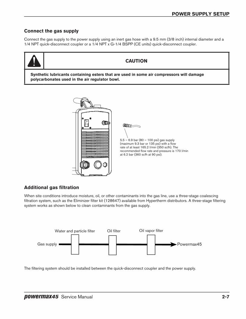
Connect the gas supply
Connect the gas supply to the power supply using an inert gas hose with a 9.5 mm (3/8 inch) internal diameter and a 1/4 NPT quick-disconnect coupler or a 1/4 NPT x G-1/4 BSPP (CE units) quick-disconnect coupler.
CAUTIoN
Synthetic lubricants containing esters that are used in some air compressors will damage polycarbonates used in the air regulator bowl.
Additional gas filtration
When site conditions introduce moisture, oil, or other contaminants into the gas line, use a three-stage coalescing filtration system, such as the Eliminizer filter kit (128647) available from Hypertherm distributors. A three-stage filtering system works as shown below to clean contaminants from the gas supply.
The filtering system should be installed between the quick-disconnect coupler and the power supply.
5.5 – 6.9 bar (80 – 100 psi) gas supply (maximum 9.3 bar or 135 psi) with a flow rate of at least 165.2 l/min (350 scfh). The recommended flow rate and pressure is 170 l/min at 6.2 bar (360 scfh at 90 psi).
Gas supply Powermax45
Water and particle filter Oil filter Oil vapor filter

Power suPPly setuP
2-8 powermax45 Service Manual

powermax45 Service Manual 3-1
Section 3
ToRCH SeTUP
In this section:
Introduction .................................................................................................................................................................................................3-2Consumable life ..........................................................................................................................................................................................3-2Hand torch setup .......................................................................................................................................................................................3-2
Choose the consumables ..............................................................................................................................................................3-3Install the consumables ..................................................................................................................................................................3-5
Machine torch setup..................................................................................................................................................................................3-6Mount the torch ................................................................................................................................................................................3-6Choose the consumables (cut charts) .......................................................................................................................................3-8Using the cut charts ........................................................................................................................................................................3-8T45m shielded consumables ........................................................................................................................................................3-8Align the torch ...............................................................................................................................................................................3-24Connect the remote-start pendant ...........................................................................................................................................3-25Connect a machine interface cable .........................................................................................................................................3-25Accessing raw arc voltage .........................................................................................................................................................3-27
Connect the torch lead ..........................................................................................................................................................................3-30

torch setup
3-2 powermax45 Service Manual
IntroductionBoth the T45v hand torch and the T45m machine torch are available for the Powermax45. The torch FastConnect™ system makes it easy to remove the torch for transport or to switch from one torch to the other if your applications require the use of both torches.
This section explains how to set up your torch and choose the appropriate consumables for the job.
Consumable lifeHow often you will need to change the consumables on your Powermax45 will depend on a number of factors:
• The thickness of the metal being cut.
• The length of the average cut.
• Whether you are doing machine or hand cutting.
• The air quality (presence of oil, moisture, or other contaminants).
• Whether you are piercing the metal or starting cuts from the edge.
• Proper torch-to-work distance when gouging or cutting with unshielded consumables.
• Proper pierce height.
• Which consumables you are using. The T30v (Powermax30) 30 amp consumables will have a shorter life when used on the T45v. However, they provide optimum cut quality for certain applications.
Under normal conditions, the electrode will wear out first during machine cutting, and the nozzle will wear out first when hand cutting.
A good rule of thumb is that a set of consumables will last approximately 1 to 2 hours of actual “arc on” time for hand cutting, depending on these factors. For cutting with a machine torch, consumables may last up to 3 to 5 hours.
You will find more information about proper cutting techniques in the Operation section.
Hand torch setup
ConsumablesSafety trigger
torch setup
powermax45 Service Manual 3-3
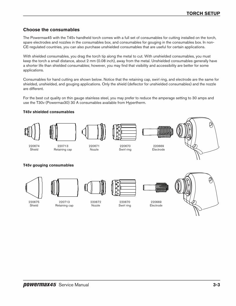
Choose the consumables
The Powermax45 with the T45v handheld torch comes with a full set of consumables for cutting installed on the torch, spare electrodes and nozzles in the consumables box, and consumables for gouging in the consumables box. In non-CE-regulated countries, you can also purchase unshielded consumables that are useful for certain applications.
With shielded consumables, you drag the torch tip along the metal to cut. With unshielded consumables, you must keep the torch a small distance, about 2 mm (0.08 inch), away from the metal. Unshielded consumables generally have a shorter life than shielded consumables; however, you may find that visibility and accessibility are better for some applications.
Consumables for hand cutting are shown below. Notice that the retaining cap, swirl ring, and electrode are the same for shielded, unshielded, and gouging applications. Only the shield (deflector for unshielded consumables) and the nozzle are different.
For the best cut quality on thin gauge stainless steel, you may prefer to reduce the amperage setting to 30 amps and use the T30v (Powermax30) 30 A consumables available from Hypertherm.
T45v shielded consumables
T45v gouging consumables
220674Shield
220713Retaining cap
220671Nozzle
220670Swirl ring
220669Electrode
220670Swirl ring
220669Electrode
220675Shield
220672Nozzle
220713Retaining cap
torch setup
3-4 powermax45 Service Manual
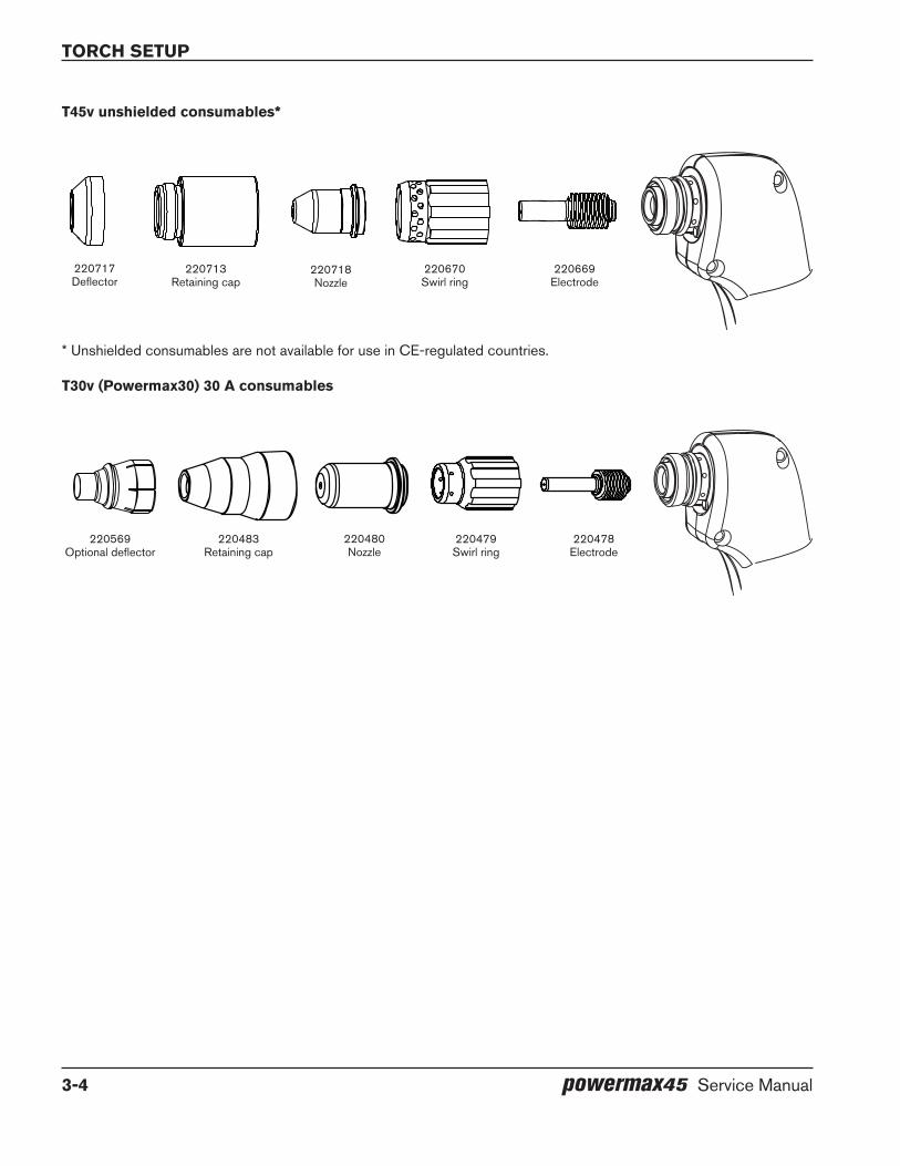
T45v unshielded consumables*
* Unshielded consumables are not available for use in CE-regulated countries.
T30v (Powermax30) 30 A consumables
220713Retaining cap
220670Swirl ring
220669Electrode
220717Deflector
220718Nozzle
220483Retaining cap
220480Nozzle
220478Electrode
220479Swirl ring
220569Optional deflector
torch setup
powermax45 Service Manual 3-5
Install the consumables
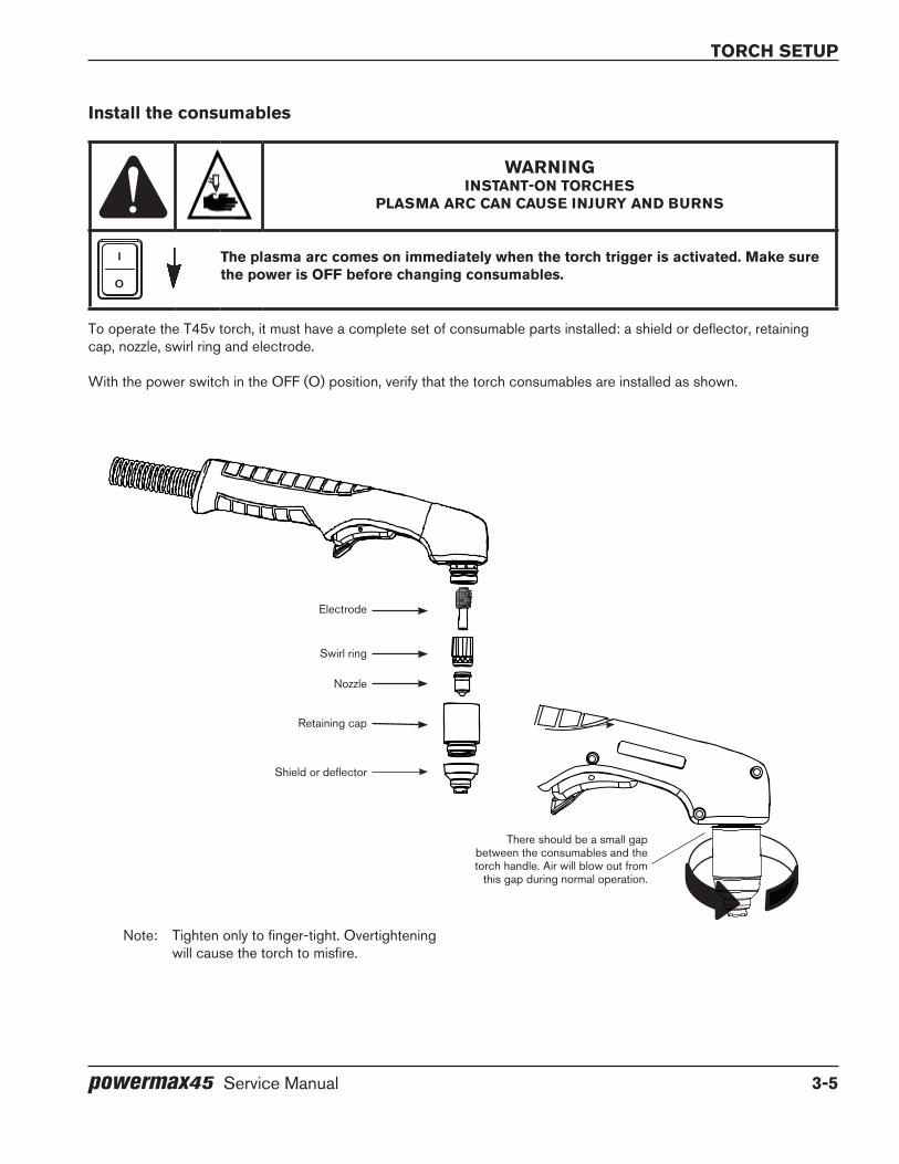
WARNINgINSTANT-oN ToRCHeS
PlASMA ARC CAN CAUSe INJURy ANd bURNS
I
O
The plasma arc comes on im me di ate ly when the torch trigger is activated. Make sure the power is off before changing consumables.
To operate the T45v torch, it must have a complete set of consumable parts installed: a shield or deflector, retaining cap, nozzle, swirl ring and electrode.
With the power switch in the OFF (O) position, verify that the torch consumables are installed as shown.
Retaining cap
Nozzle
Electrode
Swirl ring
Note: Tighten only to finger-tight. Overtightening will cause the torch to misfire.
Shield or deflector
There should be a small gap between the consumables and the torch handle. Air will blow out from
this gap during normal operation.
torch setup
3-6 powermax45 Service Manual
Machine torch setup
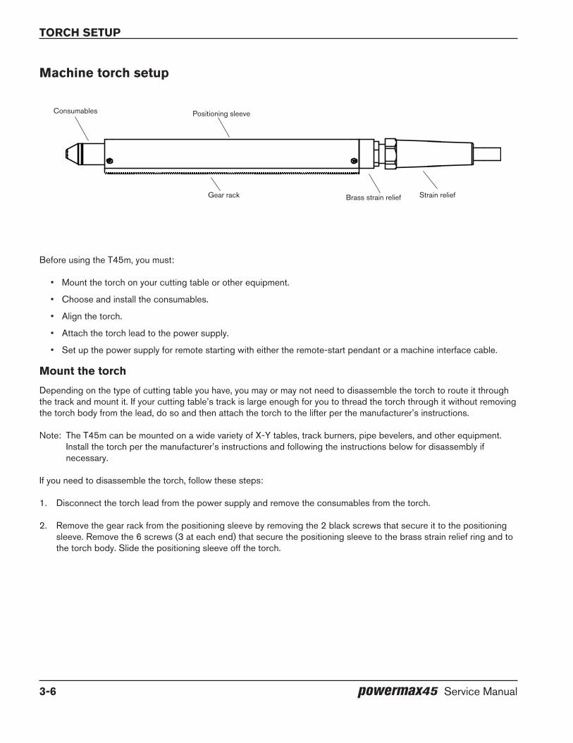
Before using the T45m, you must:
• Mount the torch on your cutting table or other equipment.
• Choose and install the consumables.
• Align the torch.
• Attach the torch lead to the power supply.
• Set up the power supply for remote starting with either the remote-start pendant or a machine interface cable.
Mount the torch
Depending on the type of cutting table you have, you may or may not need to disassemble the torch to route it through the track and mount it. If your cutting table’s track is large enough for you to thread the torch through it without removing the torch body from the lead, do so and then attach the torch to the lifter per the manufacturer’s instructions.
Note: The T45m can be mounted on a wide variety of X-Y tables, track burners, pipe bevelers, and other equipment. Install the torch per the manufacturer’s instructions and following the instructions below for disassembly if necessary.
If you need to disassemble the torch, follow these steps:
1. Disconnect the torch lead from the power supply and remove the consumables from the torch.
2. Remove the gear rack from the positioning sleeve by removing the 2 black screws that secure it to the positioning sleeve. Remove the 6 screws (3 at each end) that secure the positioning sleeve to the brass strain relief ring and to the torch body. Slide the positioning sleeve off the torch.
Consumables
Gear rack Strain relief
Positioning sleeve
Brass strain relief

torch setup
powermax45 Service Manual 3-7
3. Disconnect the wires for the cap-sensor switch at the connector in the middle.
4. Use a #2 Phillips screwdriver and a 6 mm (1/4 inch) nut driver (or adjustable wrench) to remove the screw and nut that secure the torch’s power cable to the plunger. (Turn the plunger if necessary to gain access to the screw.)
5. Use 6 mm (1/4 inch) and 10 mm (3/8 inch) or adjustable wrenches to loosen the nut that secures the gas supply line to the torch lead. Set the torch body aside.
Note: Cover the end of the gas line on the torch lead with tape to keep dirt and other contaminants from getting in the gas line when you route the lead through the track.
6. Route the torch lead through the cutting table’s track.
7. Reattach the torch’s power cable to the torch plunger using the screw and nut. Rotate the plunger so that the screw does not interfere with the cap-sensor switch.
8. Reconnect the gas line to the torch lead.
9. Press the two halves of the cap-sensor switch’s wire connector together.
10. Slide the positioning sleeve over the torch body and check the alignment of the screw holes. Replace the three screws at each end.
11. If you will be using the gear rack, re-attach it with the 2 black screws you removed earlier.
12. Attach the torch to the lifter per the manufacturer’s instructions.
Cap-sensor switch’s wire connector
Gas supply line connection
Screw to connect the power cable to the plunger
torch setup
3-8 powermax45 Service Manual
Choose the consumables (cut charts)
WARNINgINSTANT-oN ToRCHeS
PlASMA ARC CAN CAUSe INJURy ANd bURNS
I
O
The plasma arc comes on im me di ate ly when the torch trigger is activated. Make sure the power is off before changing consumables.
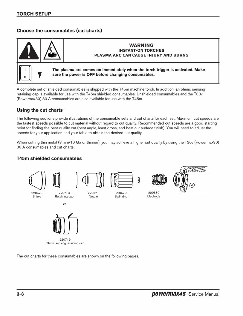
A complete set of shielded consumables is shipped with the T45m machine torch. In addition, an ohmic sensing retaining cap is available for use with the T45m shielded consumables. Unshielded consumables and the T30v (Powermax30) 30 A consumables are also available for use with the T45m.
Using the cut charts
The following sections provide illustrations of the consumable sets and cut charts for each set. Maximum cut speeds are the fastest speeds possible to cut material without regard to cut quality. Recommended cut speeds are a good starting point for finding the best quality cut (best angle, least dross, and best cut surface finish). You will need to adjust the speeds for your application and your table to obtain the desired cut quality.
When cutting thin metal (3 mm/10 Ga or thinner), you may achieve a higher cut quality by using the T30v (Powermax30) 30 A consumables and cut charts.
T45m shielded consumables
The cut charts for these consumables are shown on the following pages.
220673Shield
220713Retaining cap
or
220719Ohmic sensing retaining cap
220671Nozzle
220670Swirl ring
220669Electrode
torch setup
powermax45 Service Manual 3-9
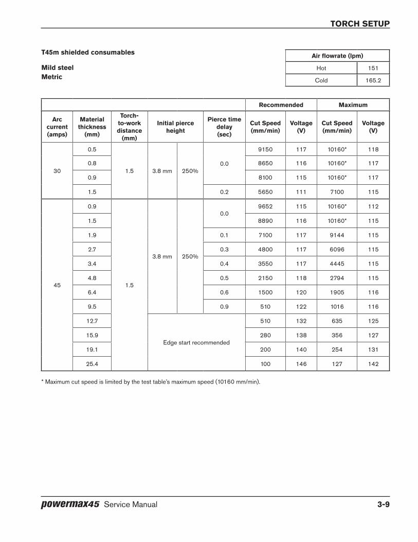
T45m shielded consumables Air flowrate (lpm)
Mild steel Hot 151Metric Cold 165.2
Recommended Maximum
Arc current(amps)
Material thickness
(mm)
Torch-to-work distance
(mm)
Initial pierce height
Pierce time delay(sec)
Cut Speed(mm/min)
Voltage(V)
Cut Speed(mm/min)
Voltage(V)
30
0.5
1.5 3.8 mm 250%0.0
9150 117 10160* 118
0.8 8650 116 10160* 117
0.9 8100 115 10160* 117
1.5 0.2 5650 111 7100 115
45
0.9
1.5
3.8 mm 250%
0.09652 115 10160* 112
1.5 8890 116 10160* 115
1.9 0.1 7100 117 9144 115
2.7 0.3 4800 117 6096 115
3.4 0.4 3550 117 4445 115
4.8 0.5 2150 118 2794 115
6.4 0.6 1500 120 1905 116
9.5 0.9 510 122 1016 116
12.7
Edge start recommended
510 132 635 125
15.9 280 138 356 127
19.1 200 140 254 131
25.4 100 146 127 142
* Maximum cut speed is limited by the test table’s maximum speed (10160 mm/min).

torch setup
3-10 powermax45 Service Manual
T45m shielded consumables Air flowrate (scfh)
Mild steel Hot 320english Cold 360
Recommended Maximum
Arc current(amps)
Material thickness
Torch-to-work distance
(in)
Initial pierce height
Pierce time delay(sec)
Cut Speed(ipm)
Voltage(V)
Cut Speed(ipm)
Voltage(V)
30
0.018 in(26 Ga)
0.06 0.15 in 250%0.0
360 117 400* 118
0.030 in(22 Ga) 340 116 400* 117
0.036 in(20 Ga) 320 115 400* 117
0.060 in(16 Ga) 0.2 225 111 280 115
45
0.036 in(20 Ga)
0.06
0.15 in 250%
0.0380 115 400* 112
0.060 in(16 Ga) 350 116 400* 115
0.075 in(14 Ga) 0.1 280 117 360 115
0.105 in(12 Ga) 0.3 190 117 240 115
0.135 in(10 Ga) 0.4 140 117 175 115
0.188 in(3/16 in) 0.5 85 118 110 115
0.250 in(1/4 in) 0.6 60 120 75 116
0.375 in(3/8 in) 0.9 32 122 40 116
0.500 in(1/2 in)
Edge start recommended
20 132 25 125
0.625 in(5/8 in) 11 138 14 127
0.750 in(3/4 in) 8 140 10 131
1.000 in(1 in) 4 146 5 142
* Maximum cut speed is limited by the test table’s maximum speed (400 ipm).

torch setup
powermax45 Service Manual 3-11
T45m shielded consumables Air flowrate (lpm)
Stainless steel Hot 151Metric Cold 165.2
Recommended Maximum
Arc current(amps)
Material thickness
(mm)
Torch-to-work distance
(mm)
Initial pierce height
Pierce time delay(sec)
Cut Speed(mm/min)
Voltage(V)
Cut Speed(mm/min)
Voltage(V)
30
0.5
1.5 3.8 mm 250%0.0
9150 119 10160* 123
0.8 8650 117 10160* 121
0.9 8100 115 10160* 119
1.5 0.2 3750 113 4700 118
45
0.9
1.5
3.8 mm 250%
0.07600 112 10160* 109
1.5 8100 112 10160* 125
1.9 0.1 7100 118 9144 115
2.7 0.3 4050 118 5080 116
3.4 0.4 3050 121 3810 118
4.8 0.5 1780 122 2159 118
6.4 0.6 1100 124 1397 120
9.5 0.8 760 126 813 121
12.7Edge start recommended
350 132 457 128
19.1 175 136 229 131
* Maximum cut speed is limited by the test able’s maximum speed (10160 mm/min).

torch setup
3-12 powermax45 Service Manual
T45m shielded consumablesAir flowrate (scfh)
Stainless steel Hot 320
englishCold 360
Recommended Maximum
Arc current(amps)
Material thickness
Torch-to-work distance
(in)
Initial pierce height
Pierce time delay(sec)
Cut Speed(ipm)
Voltage(V)
Cut Speed(ipm)
Voltage(V)
30
0.018 in(26 Ga)
0.06 0.15 in 250%0.0
360 117 400* 123
0.030 in(22 Ga) 340 116 400* 121
0.036 in(20 Ga) 320 115 400* 119
0.060 in(16 Ga) 0.2 145 111 185 118
45
0.036 in(20 Ga)
0.06
0.15 in 250%
0.0300 115 400* 109
0.060 in(16 Ga) 320 116 400* 125
0.075 in(14 Ga) 0.1 280 117 360 115
0.105 in(12 Ga) 0.3 160 117 200 116
0.135 in(10 Ga) 0.4 120 117 150 118
0.188 in(3/16 in) 0.5 70 118 85 118
0.250 in(1/4 in) 0.6 44 120 55 120
0.375 in(3/8 in) 0.8 30 122 32 121
0.500 in(1/2 in)
Edge start recommended14 132 18 128
0.750 in(3/4 in) 7 140 9 131
* Maximum cut speed is limited by the test table’s maximum speed (400 ipm).
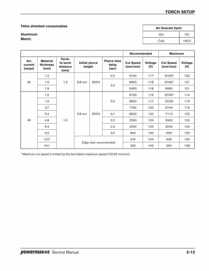
torch setup
powermax45 Service Manual 3-13
T45m shielded consumables Air flowrate (lpm)
Aluminum Hot 151Metric Cold 165.2
Recommended Maximum
Arc current(amps)
Material thickness
(mm)
Torch-to-work distance
(mm)
Initial pierce height
Pierce time delay(sec)
Cut Speed(mm/min)
Voltage(V)
Cut Speed(mm/min)
Voltage(V)
30
1.2
1.5 3.8 mm 250%
0.0 9150 117 10160* 120
1.50.2
8650 118 10160* 121
1.9 5450 118 6860 121
45
1.5
1.5
3.8 mm 250%
0.0
9150 116 10160* 114
1.9 8650 117 10160 116
2.7 7100 120 9144 119
3.4 0.1 5600 122 7112 120
4.8 0.2 2550 123 3302 120
6.4 0.3 2050 123 2540 120
9.5 0.5 840 130 1067 125
12.7Edge start recommended
510 134 635 130
19.1 200 143 254 138
* Maximum cut speed is limited by the test table’s maximum speed (10160 mm/min).
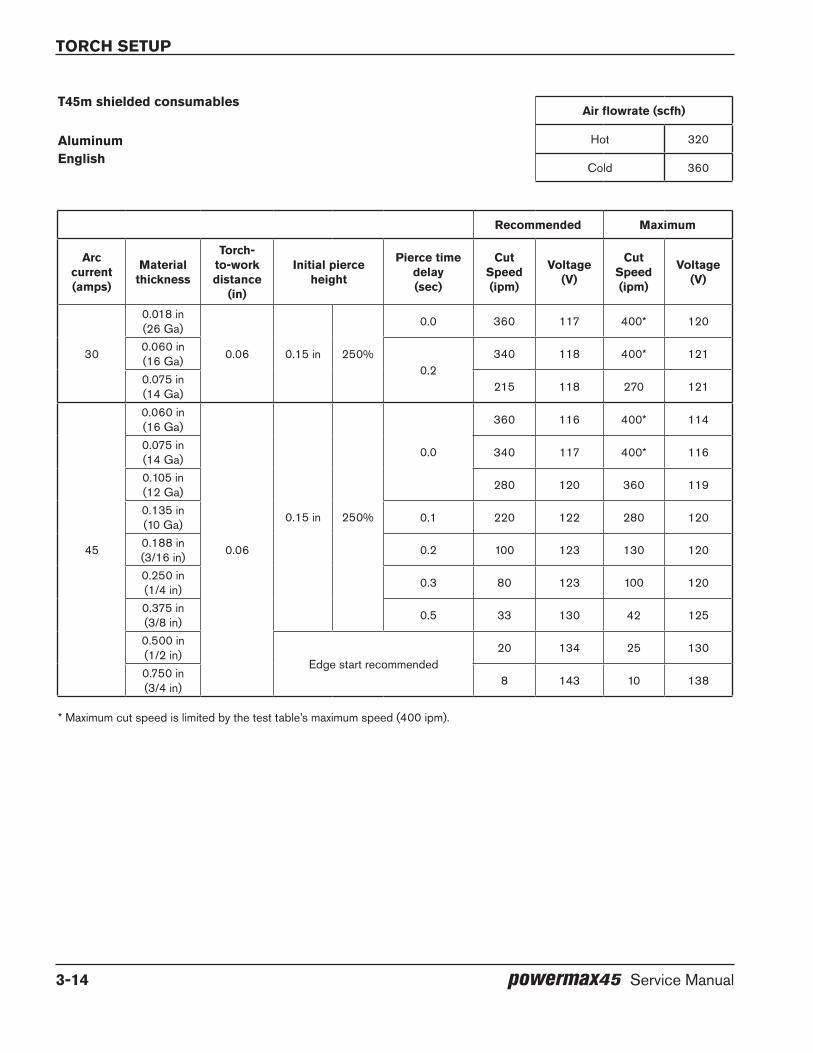
torch setup
3-14 powermax45 Service Manual
T45m shielded consumablesAir flowrate (scfh)
Aluminum Hot 320
englishCold 360
Recommended Maximum
Arc current(amps)
Material thickness
Torch-to-work distance
(in)
Initial pierce height
Pierce time delay(sec)
Cut Speed(ipm)
Voltage(V)
Cut Speed(ipm)
Voltage(V)
30
0.018 in(26 Ga)
0.06 0.15 in 250%
0.0 360 117 400* 120
0.060 in(16 Ga)
0.2340 118 400* 121
0.075 in(14 Ga) 215 118 270 121
45
0.060 in(16 Ga)
0.06
0.15 in 250%
0.0
360 116 400* 114
0.075 in(14 Ga) 340 117 400* 116
0.105 in(12 Ga) 280 120 360 119
0.135 in(10 Ga) 0.1 220 122 280 120
0.188 in(3/16 in) 0.2 100 123 130 120
0.250 in(1/4 in) 0.3 80 123 100 120
0.375 in(3/8 in) 0.5 33 130 42 125
0.500 in(1/2 in)
Edge start recommended20 134 25 130
0.750 in(3/4 in) 8 143 10 138
* Maximum cut speed is limited by the test table’s maximum speed (400 ipm).

torch setup
powermax45 Service Manual 3-15
T45m unshielded consumables
220713Retaining cap
220670Swirl ring
220669Electrode
220717Deflector
220718Nozzle
Mild steel Air flowrate (lpm)Metric Hot 151
Cold 165.2
Recommended Maximum
Arc current(amps)
Material thickness
(mm)
Torch-to-work distance
(mm)
Initial pierce height
Pierce time delay(sec)
Cut Speed(mm/min)
Voltage(V)
Cut Speed(mm/min)
Voltage(V)
30
0.5
2.0 5.0 mm 250%0.0
9150 118 10160* 114
0.8 8650 118 10160* 116
0.9 8100 117 10160* 120
1.5 0.2 5800 113 7250 119
45
0.9
2.0
5.0 mm 250%
0.0
9650 118 10160* 110
1.5 8900 114 10160* 113
1.9 6100 114 7620 114
2.7 0.3 4450 116 5588 114
3.4 0.4 3400 118 4318 116
4.8 0.4 2150 118 2794 116
6.4 0.5 1500 118 1905 118
9.5 0.7 810 120 1016 118
12.7
Edge start recommended
510 130 635 124
15.9 280 132 356 126
19.1 200 138 254 132
25.4 100 145 127 140
* Maximum cut speed is limited by the test table’s maximum speed (10160 mm/min).

torch setup
3-16 powermax45 Service Manual
T45m unshielded consumables Air flowrate (scfh)
Mild steel Hot 320english Cold 360
Recommended Maximum
Arc current(amps)
Material thickness
Torch-to-work distance
(in)
Initial pierce height
Pierce time delay(sec)
Cut Speed(ipm)
Voltage(V)
Cut Speed(ipm)
Voltage(V)
30
0.018 in(26 Ga)
0.08 0.2 in 250%0.0
360 118 400* 114
0.030 in(22 Ga) 340 118 400* 116
0.036 in(20 Ga) 320 117 400* 120
0.060 in(16 Ga) 0.2 225 113 285 119
45
0.036 in(20 Ga)
0.08
0.2 in 250%
0.0
380 118 400* 110
0.060 in(16 Ga) 350 114 400* 113
0.075 in(14 Ga) 240 114 300 114
0.105 in(12 Ga) 0.3 175 116 220 114
0.135 in(10 Ga) 0.4 135 118 170 116
0.188 in(3/16 in) 0.4 85 118 110 116
0.250 in(1/4 in) 0.5 60 118 75 118
0.375 in(3/8 in) 0.7 32 120 40 118
0.500 in(1/2 in)
Edge start recommended
20 130 25 124
0.625 in(5/8 in) 11 132 14 126
0.750 in(3/4 in) 8 138 10 132
1.000 in(1 in) 4 145 5 140
* Maximum cut speed is limited by the test table’s maximum speed (400 ipm).

torch setup
powermax45 Service Manual 3-17
T45m unshielded consumables Air flowrate (lpm)
Stainless steel Hot 151Metric Cold 165.2
Recommended Maximum
Arc current(amps)
Material thickness
(mm)
Torch-to-work distance
(mm)
Initial pierce height
Pierce time delay(sec)
Cut Speed(mm/min)
Voltage(V)
Cut Speed(mm/min)
Voltage(V)
30
0.5
2.0 5.0 mm 250%0.0
9144 113 10160* 125
0.8 8128 115 10160* 128
0.9 7000 114 9000 125
1.5 0.2 3650 112 4800 118
45
0.9
2.0
5.0 mm 250%
0.08900 112 10160* 110
1.5 8100 115 10160* 113
1.9 0.1 7112 116 9144 114
2.7 0.3 4100 118 5080 116
3.4 0.4 2800 120 3556 118
4.8 0.5 1650 120 2032 118
6.4 0.6 1010 121 1270 118
9.5 0.8 610 125 762 120
12.7Edge start recommended
355 130 457 126
19.1 175 133 229 138
* Maximum cut speed is limited by the test table’s maximum speed (10160 mm/min).
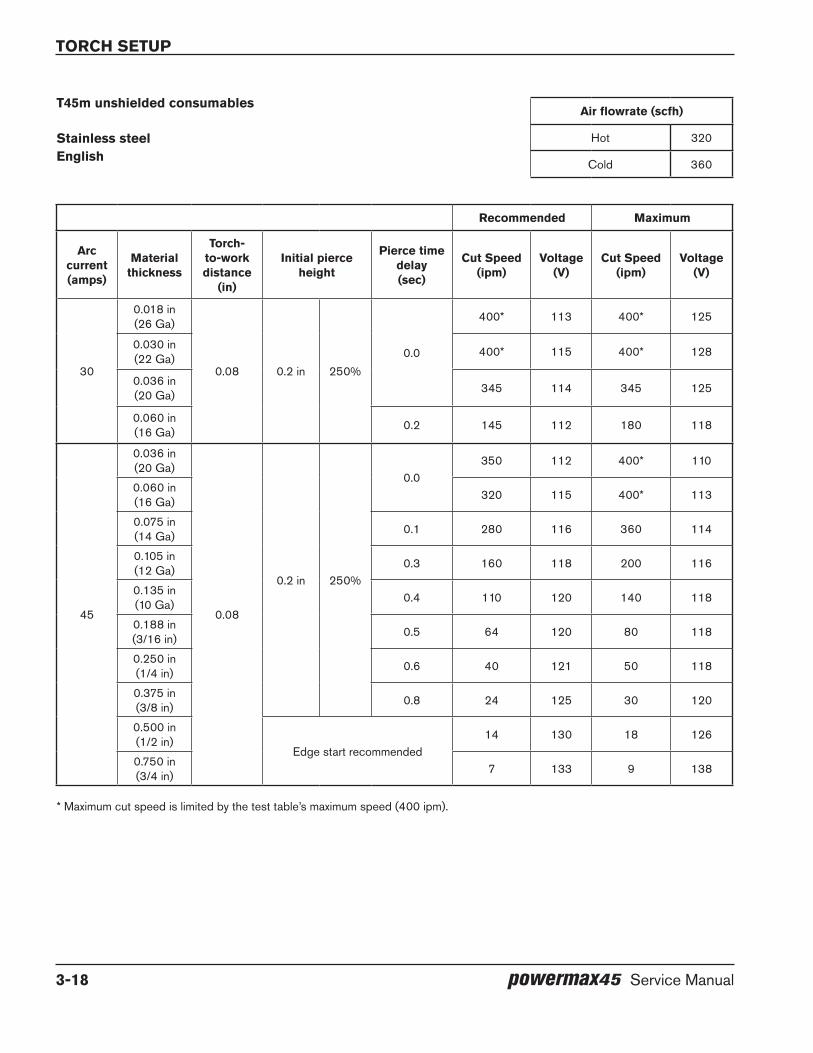
torch setup
3-18 powermax45 Service Manual
T45m unshielded consumablesAir flowrate (scfh)
Stainless steel Hot 320english
Cold 360
Recommended Maximum
Arc current(amps)
Material thickness
Torch-to-work distance
(in)
Initial pierce height
Pierce time delay(sec)
Cut Speed(ipm)
Voltage(V)
Cut Speed(ipm)
Voltage(V)
30
0.018 in(26 Ga)
0.08 0.2 in 250%0.0
400* 113 400* 125
0.030 in(22 Ga) 400* 115 400* 128
0.036 in(20 Ga) 345 114 345 125
0.060 in(16 Ga) 0.2 145 112 180 118
45
0.036 in(20 Ga)
0.08
0.2 in 250%
0.0350 112 400* 110
0.060 in(16 Ga) 320 115 400* 113
0.075 in(14 Ga) 0.1 280 116 360 114
0.105 in(12 Ga) 0.3 160 118 200 116
0.135 in(10 Ga) 0.4 110 120 140 118
0.188 in(3/16 in) 0.5 64 120 80 118
0.250 in(1/4 in) 0.6 40 121 50 118
0.375 in(3/8 in) 0.8 24 125 30 120
0.500 in(1/2 in)
Edge start recommended14 130 18 126
0.750 in(3/4 in) 7 133 9 138
* Maximum cut speed is limited by the test table’s maximum speed (400 ipm).

torch setup
powermax45 Service Manual 3-19
T45m unshielded consumables Air flowrate (lpm)
Aluminum Hot 151Metric Cold 165.2
Recommended Maximum
Arc current(amps)
Material thickness
(mm)
Torch-to-work distance
(mm)
Initial pierce height
Pierce time delay(sec)
Cut Speed(mm/min)
Voltage(V)
Cut Speed(mm/min)
Voltage(V)
30
1.2
2.0 5.0 mm 250%
0.0 8900 122 10160* 121
1.5 0.1 8100 120 10160* 118
1.9 0.2 5700 121 7100 119
45
1.5
2.0
5.0 mm 250%
0.0
8900 120 10160* 116
1.9 8100 120 10160* 116
2.7 7200 122 9144 118
3.4 0.1 5500 123 6858 118
4.8 0.3 2540 123 3175 118
6.4 0.3 1820 128 2286 124
9.5 0.5 710 130 914 124
12.7Edge start recommended
510 131 635 125
19.1 200 148 254 143
* Maximum cut speed is limited by the test table’s maximum speed (10160 mm/min).

torch setup
3-20 powermax45 Service Manual
T45m unshielded consumablesAir flowrate (scfh)
Aluminum Hot 320
englishCold 360
Recommended Maximum
Arc current(amps)
Material thickness
Torch-to-work distance
(in)
Initial pierce height
Pierce time delay(sec)
Cut Speed(ipm)
Voltage(V)
Cut Speed(ipm)
Voltage(V)
30
0.018 in(26 Ga)
0.08 0.20 in 250%
0.0 350 122 400* 121
0.060 in(16 Ga) 0.1 320 120 400* 118
0.075 in(14 Ga) 0.2 225 121 280 119
45
0.060 in(16 Ga)
0.08
0.20 in 250%
0.0
350 120 400* 116
0.075 in(14 Ga) 320 120 400* 116
0.105 in(12 Ga) 285 122 360 118
0.135 in(10 Ga) 0.1 215 123 270 118
0.188 in(3/16 in) 0.3 100 123 125 118
0.250 in(1/4 in) 0.3 72 128 90 124
0.375 in(3/8 in) 0.5 28 130 36 124
0.500 in(1/2 in)
Edge start recommended20 131 25 125
0.750 in(3/4 in) 8 148 10 143
* Maximum cut speed is limited by the test table’s maximum speed (400 ipm).

torch setup
powermax45 Service Manual 3-21
T30v (Powermax30) 30 A consumables
220483Retaining cap
220480Nozzle
220478Electrode
220479Swirl ring
220569Optional deflector
Mild steel Air flowrate (lpm)Metric Hot 131.2
Cold 146.3
Recommended Maximum
Arc current(amps)
Material thickness
(mm)
Torch-to-work distance
(mm)
Initial pierce height
Pierce time delay(sec)
Cut Speed(mm/min)
Voltage(V)
Cut Speed(mm/min)
Voltage(V)
30
0.5
0.5 2.5 mm 500%
0.0
8900 105 10160* 98
0.8 8100 102 10160* 103
0.9 7100 101 8900 100
1.5 0.2 4450 97 5600 100
1.9
0.4
3050 98 3800 97
2.7 2050 96 2550 96
3.4 1270 100 1650 101
* Maximum cut speed is limited by the test table’s maximum speed (10160 mm/min).

torch setup
3-22 powermax45 Service Manual
T30v (Powermax30) 30 A consumables Air flowrate (scfh)
Mild steel Hot 280english Cold 310
Recommended Maximum
Arc current(amps)
Material thickness
(in)
Torch-to-work distance
(in)
Initial pierce height
Pierce time delay(sec)
Cut Speed(ipm)
Voltage(V)
Cut Speed(ipm)
Voltage(V)
30
0.018(26 Ga)
0.02 0.1 in 500%
0.0
350 105 400* 98
0.030(22 Ga) 320 102 400* 103
0.036(20 Ga) 280 101 350 100
0.060(16 Ga) 0.2 175 97 220 100
0.075(14 Ga)
0.4
120 98 150 97
0.105(12 Ga) 80 96 100 96
0.135(10 Ga) 50 100 65 101
T30v (Powermax30) 30 A consumables Air flowrate (lpm)
Stainless steel Hot 131.2Metric Cold 146.3
Recommended Maximum
Arc current(amps)
Material thickness
(mm)
Torch-to-work distance
(mm)
Initial pierce height
Pierce time delay(sec)
Cut Speed(mm/min)
Voltage(V)
Cut Speed(mm/min)
Voltage(V)
30
0.5
0.5 2.5 mm 500%
0.0
8900 103 10160* 102
0.8 8100 98 10160* 100
0.9 7600 97 6850 98
1.5 0.2 3800 99 4800 98
1.9
0.4
2800 101 3450 97
2.7 1500 101 1900 98
3.4 1150 102 1400 97
* Maximum cut speed is limited by the test table’s maximum speed (400 ipm or 10160 mm/min).
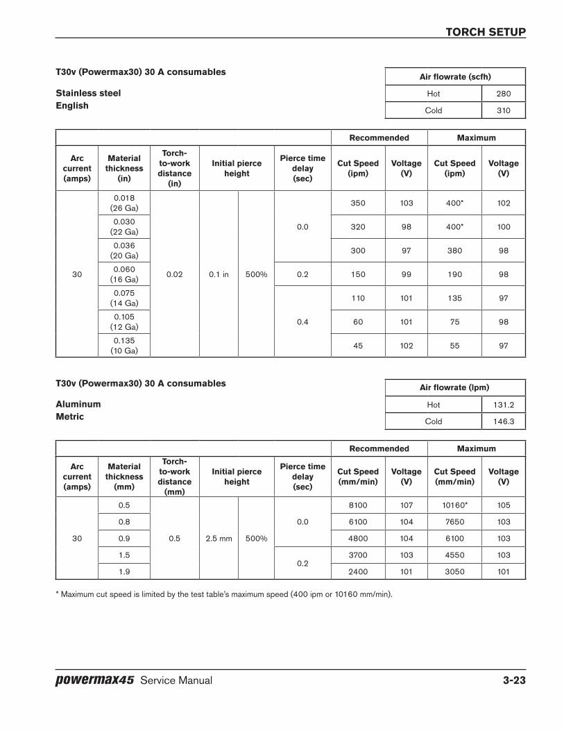
torch setup
powermax45 Service Manual 3-23
T30v (Powermax30) 30 A consumables Air flowrate (scfh)
Stainless steel Hot 280english Cold 310
Recommended Maximum
Arc current(amps)
Material thickness
(in)
Torch-to-work distance
(in)
Initial pierce height
Pierce time delay(sec)
Cut Speed(ipm)
Voltage(V)
Cut Speed(ipm)
Voltage(V)
30
0.018(26 Ga)
0.02 0.1 in 500%
0.0
350 103 400* 102
0.030(22 Ga) 320 98 400* 100
0.036(20 Ga) 300 97 380 98
0.060(16 Ga) 0.2 150 99 190 98
0.075(14 Ga)
0.4
110 101 135 97
0.105(12 Ga) 60 101 75 98
0.135(10 Ga) 45 102 55 97
T30v (Powermax30) 30 A consumables Air flowrate (lpm)
Aluminum Hot 131.2Metric Cold 146.3
Recommended Maximum
Arc current(amps)
Material thickness
(mm)
Torch-to-work distance
(mm)
Initial pierce height
Pierce time delay(sec)
Cut Speed(mm/min)
Voltage(V)
Cut Speed(mm/min)
Voltage(V)
30
0.5
0.5 2.5 mm 500%
0.0
8100 107 10160* 105
0.8 6100 104 7650 103
0.9 4800 104 6100 103
1.50.2
3700 103 4550 103
1.9 2400 101 3050 101
* Maximum cut speed is limited by the test table’s maximum speed (400 ipm or 10160 mm/min).

torch setup
3-24 powermax45 Service Manual
T30v (Powermax30) 30 A consumables Air flowrate (scfh)
Aluminum Hot 280english Cold 310
Recommended Maximum
Arc current(amps)
Material thickness
(in)
Torch-to-work distance
(in)
Initial pierce height
Pierce time delay(sec)
Cut Speed(ipm)
Voltage(V)
Cut Speed(ipm)
Voltage(V)
30
0.036(20 Ga)
0.02 0.10 in 500%
0.0
320 107 400* 105
0.060(16 Ga) 240 104 300 103
0.075(14 Ga) 190 104 240 103
0.105(12 Ga)
0.2145 103 180 103
0.135(10 Ga) 95 101 120 101
* Maximum cut speed is limited by the test table’s maximum speed (400 ipm).
Align the torch
Mount the machine torch perpendicular to the workpiece in order to get a vertical cut. Use a square to align the torch at 0° and 90°.
Torch
0°
90°

torch setup
powermax45 Service Manual 3-25
Connect the remote-start pendant
Configurations of a Powermax45 with a T45m also can include a 7.62 m / 25-foot (128650), 15.24 m / 50-foot (128651), or 22.86 m / 75-foot (128652) remote-start pendant. To use the Hypertherm remote-start pendant, plug it into the receptacle on the rear of the power supply.
Note: The remote-start pendant is for use only with a machine torch. It will not operate if a hand torch is installed.
Connect a machine interface cable
The Powermax45 is equipped with a factory-installed voltage divider that is designed to be safely connected without tools. The built-in voltage divider provides a 50:1 arc voltage. A receptacle on the rear of the power supply provides access to the 50:1 arc voltage and signals for arc transfer and plasma start.
CAUTIoN
The factory-installed internal voltage divider provides a maximum of 7 V under open circuit conditions. This is an impedance-protected functional extra low voltage (elV) output to prevent shock, energy, and fire under normal conditions at the machine interface receptacle and under single fault conditions with the machine interface wiring. The voltage divider is not fault tolerant and elV outputs do not comply with safety extra low voltage (SelV) requirements for direct connection to computer products.
Hypertherm offers several choices of machine interface cables for the Powermax45:
• To use the built-in voltage divider that provides a 50:1 arc voltage in addition to signals for arc transfer and plasma start:
— Use kit number 228350 (7.62 m, 25 feet) or 228351 (15.24 m, 50 feet) for 6 wires terminated with spade connectors. (The following diagram shows an example of spade connectors.)
— Use part number 223048 (7.62 m, 25 feet) or 123896 (15.24 m, 50 feet) for a cable terminated with a D-sub connector. (Compatible with Hypertherm’s EDGE® Pro Ti and Sensor™ PHC products.)
Receptacle for the remote-start pendant or a machine interface cable.

torch setup
3-26 powermax45 Service Manual
• To use signals for arc transfer and plasma start only, use either part number 023206 (7.62 m, 25 feet) or part number 023279 (15.24 m, 50 feet). These cables have spade connectors as shown here:
Note: The cover on the machine interface receptacle prevents dust and moisture from damaging the receptacle when not in use. This cover should be replaced if damaged or lost (127204).
Installation of the machine interface cable must be performed by a qualified service technician. To install a machine interface cable:
1. Turn OFF the power and disconnect the power cord.
2. Remove the machine interface receptacle’s cover from the rear of the power supply.
3. Connect the Hypertherm machine interface cable to the power supply.
4. If you are using a cable with a D-sub connector on the other end, plug it into the appropriate pin connector on the torch height controller or CNC. Secure it with the screws on the D-sub connector.
If you are using a cable with wires and spade connectors on the other end, terminate the machine interface cable inside the electrical enclosure of listed and certified torch height controllers or CNC controllers to prevent operator access to the connections after installation. Verify that the connections are correct and that all live parts are enclosed and protected before operating the equipment.
Note: The integration of Hypertherm equipment and customer-supplied equipment including interconnecting cords and cables, if not listed and certified as a system, is subject to inspection by local authorities at the final installation site.
The connector sockets for each type of signal available through the machine interface cable are shown below. The table on page 3-27 provides details about each signal type.
34
12
13
14
6 5
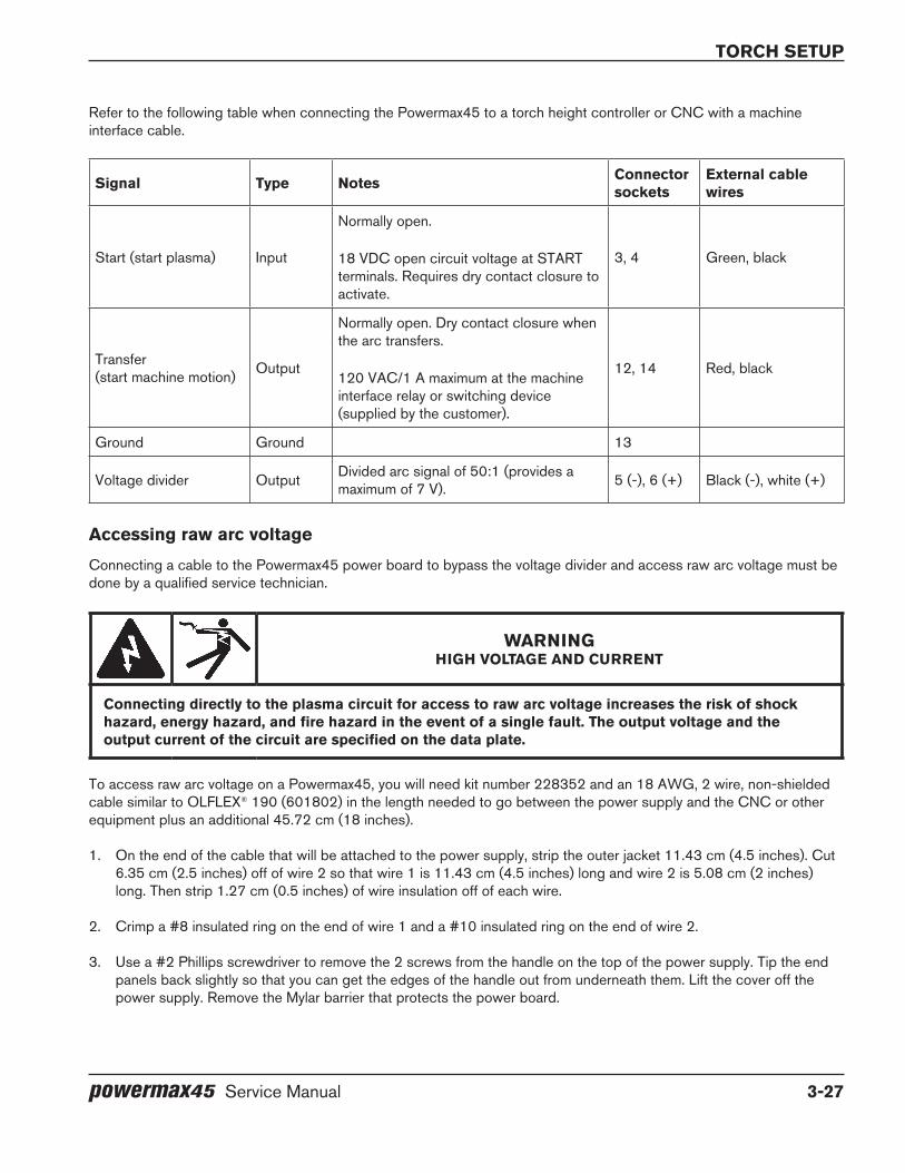
torch setup
powermax45 Service Manual 3-27
Refer to the following table when connecting the Powermax45 to a torch height controller or CNC with a machine interface cable.
Signal Type Notes Connector sockets
external cable wires
Start (start plasma) Input
Normally open.
18 VDC open circuit voltage at START terminals. Requires dry contact closure to activate.
3, 4 Green, black
Transfer (start machine motion) Output
Normally open. Dry contact closure when the arc transfers.
120 VAC/1 A maximum at the machine interface relay or switching device (supplied by the customer).
12, 14 Red, black
Ground Ground 13
Voltage divider Output Divided arc signal of 50:1 (provides a maximum of 7 V). 5 (-), 6 (+) Black (-), white (+)
Accessing raw arc voltage
Connecting a cable to the Powermax45 power board to bypass the voltage divider and access raw arc voltage must be done by a qualified service technician.
WARNINgHIgH VolTAge ANd CURReNT
Connecting directly to the plasma circuit for access to raw arc voltage increases the risk of shock hazard, energy hazard, and fire hazard in the event of a single fault. The output voltage and the output current of the circuit are specified on the data plate.
To access raw arc voltage on a Powermax45, you will need kit number 228352 and an 18 AWG, 2 wire, non-shielded cable similar to OLFLEX® 190 (601802) in the length needed to go between the power supply and the CNC or other equipment plus an additional 45.72 cm (18 inches).
1. On the end of the cable that will be attached to the power supply, strip the outer jacket 11.43 cm (4.5 inches). Cut 6.35 cm (2.5 inches) off of wire 2 so that wire 1 is 11.43 cm (4.5 inches) long and wire 2 is 5.08 cm (2 inches) long. Then strip 1.27 cm (0.5 inches) of wire insulation off of each wire.
2. Crimp a #8 insulated ring on the end of wire 1 and a #10 insulated ring on the end of wire 2.
3. Use a #2 Phillips screwdriver to remove the 2 screws from the handle on the top of the power supply. Tip the end panels back slightly so that you can get the edges of the handle out from underneath them. Lift the cover off the power supply. Remove the Mylar barrier that protects the power board.

torch setup
3-28 powermax45 Service Manual
4. Separate the rear panel from the Powermax45 by removing the screw from the bottom and backing the end panel away from the base so that there is enough room to drill out the access point without risk of hitting the interior components.
5. Use a drill with a 19/32 inch drill bit to drill out the access point on the rear panel.
6. Route the cable through the strain relief and tighten it down so that 45.72 cm (18 inches) of insulated wire is on the side of the strain relief that will go inside the power supply.
7. Thread the 45.72 cm (18 inches) of wire through the hole you drilled in the rear panel and fit the strain relief into the hole. If necessary, drill out any remaining rough spots so that the strain relief fits snugly.
8. Tighten the strain relief nut on the inside of the rear panel to hold the strain relief in place.
9. Find the grommet closest to the rear panel and at the bottom of the center panel. Route the 2 wires through the grommet to the power board side of the power supply.
Rear end panel
Access point
Rear panel pulled slightly away from the base
Grommet in center panel

torch setup
powermax45 Service Manual 3-29
10. Route the wires along the base of the unit and behind the cables connected to the power board.
11. Remove the work lead connector screw at J21 and the white wire connector screw at J19 (J18 for 400 V CE and 480 V CSA power supplies).
12. Connect wire 1 to J19 (J18 for 400 V CE and 480 V CSA power supplies) with the ring connector for wire 1 closest to the power board and the connector for the white wire closest to the head of the screw. Turn the ring connector for wire 1 upside down so that the slight bend in the ring connector base creates a little space between the wire and the board. Tighten the screw to 23.0 kg cm (20 inch-pounds).
13. Connect wire 2 to J21. This time, put the connector for the work lead closest to the power board and put the ring connector for wire 2 closest to the head of the screw. Torque the screw to 23.0 kg cm (20 inch-pounds).
14. Replace the rear panel and secure it with the screw. Replace the Mylar barrier in front of the power board. Replace the cover.
15. Connect the other end of the cable to the equipment according to the manufacturer’s instructions.
NOTE: The integration of Hypertherm equipment and customer-supplied equipment including interconnecting cords and cables, if not listed and certified as a system, is subject to inspection by local authorities at the final installation site.
TP 19W
-+ -+
TP 18R
TP 17B
192 VDC 192 VDC
J21 (work lead)
J19 or J18(white wire)

torch setup
3-30 powermax45 Service Manual
Connect the torch leadThe Powermax45 has a FastConnect system for connecting and disconnecting the hand and machine torches. When connecting or disconnecting a torch, first power OFF the system. To connect either torch, push the connector into receptacle on the front of the power supply.
To remove the torch, press the red button on the connector and pull the connector out of the receptacle.
Red button
powermax45 Service Manual 4-1
Section 4
oPeRATIoN
In this section:
Controls and indicators ............................................................................................................................................................................4-2Front controls and LEDs ................................................................................................................................................................4-2Rear controls ....................................................................................................................................................................................4-3
Operate the Powermax45 ........................................................................................................................................................................4-3Connect the electrical power and gas supply ..........................................................................................................................4-3Power ON the system ....................................................................................................................................................................4-4Set the mode switch .......................................................................................................................................................................4-4Adjust the gas pressure .................................................................................................................................................................4-4Check the indicator LEDs .............................................................................................................................................................4-6Attach the work clamp ...................................................................................................................................................................4-6
Understand duty-cycle limitations ..........................................................................................................................................................4-6How to use the hand torch ......................................................................................................................................................................4-7
Operate the safety trigger .............................................................................................................................................................4-7Hand torch cutting hints ................................................................................................................................................................4-7Start a cut from the edge of the workpiece ..............................................................................................................................4-8Pierce a workpiece ..........................................................................................................................................................................4-9Gouge a workpiece ..................................................................................................................................................................... 4-10Common hand-cutting faults .....................................................................................................................................................4-12
How to use the machine torch .............................................................................................................................................................4-12Ensure the torch and table are set up correctly ....................................................................................................................4-12Understand and optimize cut quality ........................................................................................................................................4-13To pierce a workpiece using the machine torch ....................................................................................................................4-14Common machine-cutting faults ...............................................................................................................................................4-15
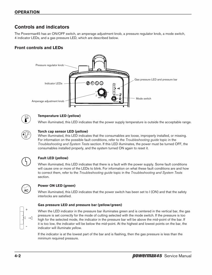
operation
4-2 powermax45 Service Manual
Controls and indicatorsThe Powermax45 has an ON/OFF switch, an amperage adjustment knob, a pressure regulator knob, a mode switch, 4 indicator LEDs, and a gas pressure LED, which are described below.
front controls and leds
Temperature led (yellow)
When illuminated, this LED indicates that the power supply temperature is outside the acceptable range.
Torch cap sensor led (yellow)When illuminated, this LED indicates that the consumables are loose, improperly installed, or missing. For information on the possible fault conditions, refer to the Troubleshooting guide topic in the Troubleshooting and System Tests section. If this LED illuminates, the power must be turned OFF, the consumables installed properly, and the system turned ON again to reset it.
fault led (yellow)
When illuminated, this LED indicates that there is a fault with the power supply. Some fault conditions will cause one or more of the LEDs to blink. For information on what these fault conditions are and how to correct them, refer to the Troubleshooting guide topic in the Troubleshooting and System Tests section.
AC
Power oN led (green)
When illuminated, this LED indicates that the power switch has been set to I (ON) and that the safety interlocks are satisfied.
gas pressure led and pressure bar (yellow/green)
When the LED indicator in the pressure bar illuminates green and is centered in the vertical bar, the gas pressure is set correctly for the mode of cutting selected with the mode switch. If the pressure is too high for the selected mode, the indicator in the pressure bar will be above the mid-point of the bar. If it is too low, the indicator will be below the mid-point. At the highest and lowest points on the bar, the indicator will illuminate yellow.
If the indicator is at the lowest part of the bar and is flashing, then the gas pressure is less than the minimum required pressure.
4020
45AMPS
30
Pressure regulator knob
Indicator LEDsGas pressure LED and pressure bar
Mode switchAmperage adjustment knob

operation
powermax45 Service Manual 4-3
45
30
40
Amperage adjustment knob
Set this knob to the gas test position (fully counter-clockwise) before adjusting the gas pressure with the pressure regulator knob on the top of the power supply. Once the gas pressure is set, turn the knob clockwise to set the output amperage. The torch will not fire when the knob is in gas-test position.
Mode switch and leds
The mode switch can be set in one of three positions:
• Continuous pilot arc to cut expanded metal or grate (top).
• Non-continuous pilot arc to cut metal plate (middle).
• Gouging (bottom).
After you change the mode switch, verify that the gas pressure is still set correctly. Different modes of cutting require different pressure settings.
Rear controls
200–240 V CSA / 230 V Ce 400 V Ce / 480 V CSA
I
O
I
O oN (I)/off (o) power switch Activates the power supply and its control circuits.
operate the Powermax45Follow the steps below to begin cutting or gouging with the Powermax45.
Connect the electrical power and gas supply
Plug in the power cord and connect the gas supply line. For more information about the electrical requirements and the gas supply requirements of the Powermax45, see the Power Supply Setup section.
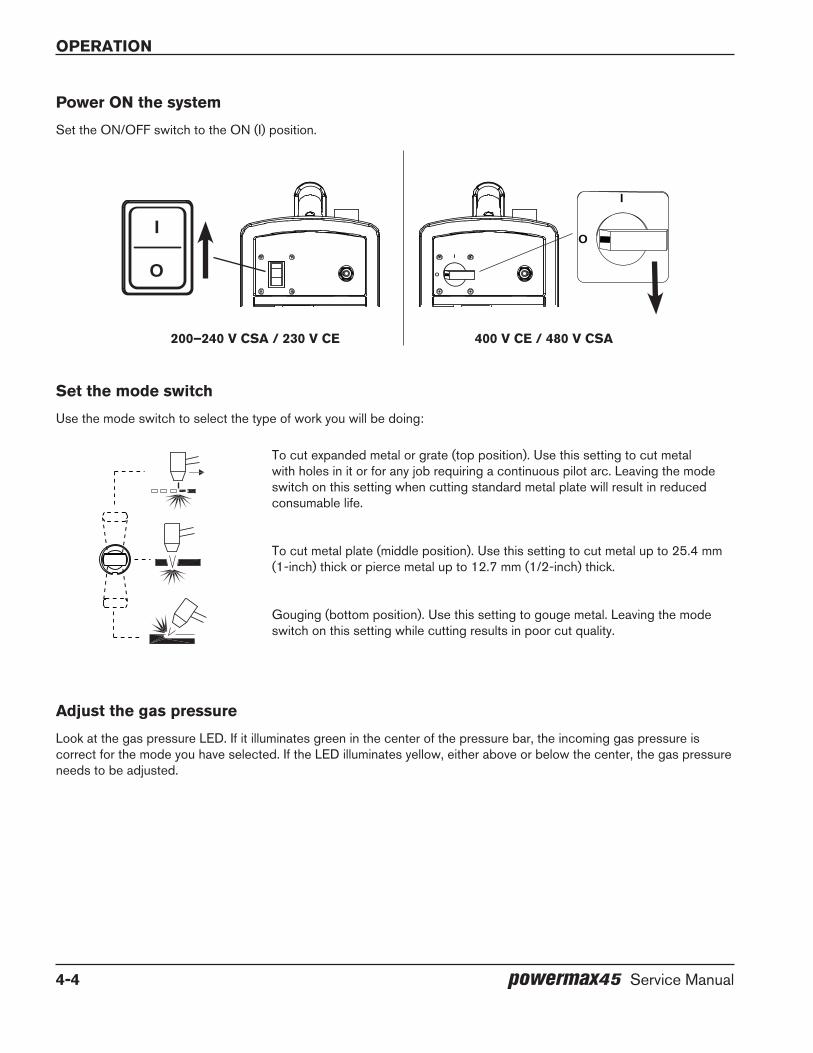
operation
4-4 powermax45 Service Manual
Power oN the system
Set the ON/OFF switch to the ON (I) position.
Set the mode switch
Use the mode switch to select the type of work you will be doing:
To cut expanded metal or grate (top position). Use this setting to cut metal with holes in it or for any job requiring a continuous pilot arc. Leaving the mode switch on this setting when cutting standard metal plate will result in reduced consumable life.
To cut metal plate (middle position). Use this setting to cut metal up to 25.4 mm (1-inch) thick or pierce metal up to 12.7 mm (1/2-inch) thick.
Gouging (bottom position). Use this setting to gouge metal. Leaving the mode switch on this setting while cutting results in poor cut quality.
Adjust the gas pressure
Look at the gas pressure LED. If it illuminates green in the center of the pressure bar, the incoming gas pressure is correct for the mode you have selected. If the LED illuminates yellow, either above or below the center, the gas pressure needs to be adjusted.
I
O
I
OI
O
200–240 V CSA / 230 V Ce 400 V Ce / 480 V CSA
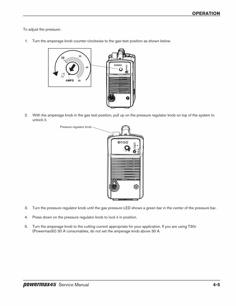
operation
powermax45 Service Manual 4-5
To adjust the pressure:
1. Turn the amperage knob counter-clockwise to the gas-test position as shown below.
2. With the amperage knob in the gas test position, pull up on the pressure regulator knob on top of the system to unlock it.
3. Turn the pressure regulator knob until the gas pressure LED shows a green bar in the center of the pressure bar.
4. Press down on the pressure regulator knob to lock it in position.
5. Turn the amperage knob to the cutting current appropriate for your application. If you are using T30v (Powermax30) 30 A consumables, do not set the amperage knob above 30 A.
45
30
40
4020
45AMPS
30
Pressure regulator knob

operation
4-6 powermax45 Service Manual
Check the indicator leds
Verify that the green power ON LED on the front of the power supply is illuminated, that the gas pressure LED shows a green bar in the center of the gauge, and that none of the other LEDs are illuminated or blinking. If the temperature, torch cap sensor, or fault LEDs are illuminated or blinking, or if the power ON LED blinks, correct the fault condition before continuing. See the Troubleshooting guide topic in the Troubleshooting and System Tests section for more information.
Attach the work clamp
The work clamp must be attached to the workpiece while you are cutting.
Note: If you are using the Powermax45 with a cutting table, you can ground it through the table instead of using the work clamp. See your table manufacturer’s instructions for more information.
• Ensure that the work clamp and the workpiece make good metal-to-metal contact.
• For the best cut quality, attach the work clamp as close as possible to the area being cut.
• do not attach the work clamp to the portion of the workpiece to be cut away.
When the power ON LED is illuminated, none of the other LEDs are illuminated or blinking, the gas pressure LED indicates pressure is in the correct range, the amperage knob is set, and the work clamp is attached, the system is ready for use.
Understand duty-cycle limitationsThe duty cycle is the amount of time, in minutes, that a plasma arc can remain on within a 10-minute period when operating at an ambient temperature of 40° C (104° F). With a Powermax45:
• At 45 A, the arc can remain on for 5 minutes out of 10 minutes without causing the unit to overheat (50% duty cycle).
• At 41 A, the arc can remain on for 6 minutes out of 10 (60%).
• At 32 A, the arc can remain on for 10 minutes out of 10 (100%).
If the power supply overheats because the duty cycle is exceeded, the temperature LED will illuminate, the arc will shut off, and the cooling fan will continue to run. To resume cutting, wait for the temperature LED to extinguish.
Work clamp
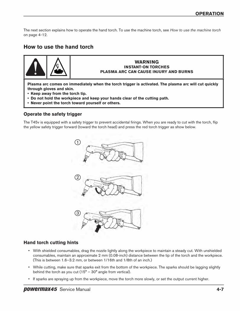
operation
powermax45 Service Manual 4-7
The next section explains how to operate the hand torch. To use the machine torch, see How to use the machine torch on page 4-12.
How to use the hand torch
WARNINgINSTANT-oN ToRCHeS
PlASMA ARC CAN CAUSe INJURy ANd bURNS
Plasma arc comes on im me di ate ly when the torch trigger is activated. The plasma arc will cut quickly through gloves and skin.• Keep away from the torch tip.• Do not hold the workpiece and keep your hands clear of the cutting path.• Never point the torch toward yourself or others.
operate the safety trigger
The T45v is equipped with a safety trigger to prevent accidental firings. When you are ready to cut with the torch, flip the yellow safety trigger forward (toward the torch head) and press the red torch trigger as show below.
Hand torch cutting hints
• With shielded consumables, drag the nozzle lightly along the workpiece to maintain a steady cut. With unshielded consumables, maintain an approximate 2 mm (0.08-inch) distance between the tip of the torch and the workpiece. (This is between 1.6–3.2 mm, or between 1/16th and 1/8th of an inch.)
• While cutting, make sure that sparks exit from the bottom of the workpiece. The sparks should be lagging slightly behind the torch as you cut (15° – 30° angle from vertical).
• If sparks are spraying up from the workpiece, move the torch more slowly, or set the output current higher.
1
2
3
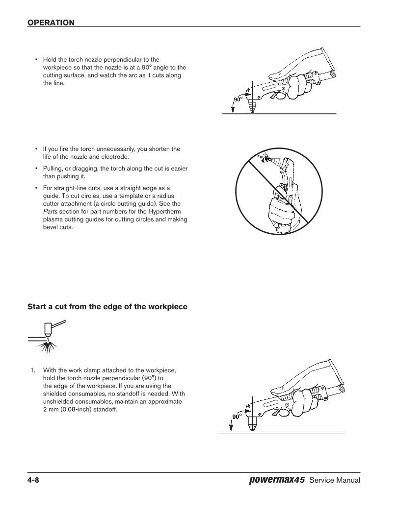
operation
4-8 powermax45 Service Manual
Start a cut from the edge of the workpiece
• If you fire the torch unnecessarily, you shorten the life of the nozzle and electrode.
• Pulling, or dragging, the torch along the cut is easier than pushing it.
• For straight-line cuts, use a straight edge as a guide. To cut circles, use a template or a radius cutter attachment (a circle cutting guide). See the Parts section for part numbers for the Hypertherm plasma cutting guides for cutting circles and making bevel cuts.
• Hold the torch nozzle perpendicular to the workpiece so that the nozzle is at a 90° angle to the cutting surface, and watch the arc as it cuts along the line.
1. With the work clamp attached to the workpiece, hold the torch nozzle perpendicular (90°) to the edge of the workpiece. If you are using the shielded consumables, no standoff is needed. With unshielded consumables, maintain an approximate 2 mm (0.08-inch) standoff.

operation
powermax45 Service Manual 4-9
2. Press the torch trigger to start the arc. Pause at the edge until the arc has cut completely through the workpiece.
3. Drag the nozzle lightly across the workpiece to proceed with the cut. Maintain a steady, even pace.
Pierce a workpiece
WARNINg
SPARKS AND HOT METAL CAN INJURE EYES AND BURN SKIN. When firing the torch at an angle, sparks and hot metal will spray out from the nozzle. Point the torch away from yourself and others.
1. With the work clamp attached to the workpiece, hold the torch at an approximate 30° angle to the workpiece with the nozzle within 1.5 mm (1/16 inch) of it before firing the torch.
2. Fire the torch while still at an angle to the workpiece, then slowly rotate the torch to a perpendicular (90°) position.

operation
4-10 powermax45 Service Manual
gouge a workpiece
WARNINg
SPARKS AND HOT METAL CAN INJURE EYES AND BURN SKIN. When firing the torch at an angle, sparks and hot metal will spray out from the nozzle. Point the torch away from yourself and others.
1. Hold the torch so that the nozzle is within 1.5 mm (1/16 inch) from the workpiece before firing the torch.
3. Hold the torch in place while continuing to press the trigger. When sparks exit from the bottom of the workpiece, the arc has pierced the material.
4. When the pierce is complete, drag the nozzle lightly along the workpiece to proceed with the cut.
2. Hold the torch at a 45° angle to the workpiece with a small gap between the torch tip and the workpiece. Press the trigger to obtain a pilot arc. Transfer the arc to the workpiece.

operation
powermax45 Service Manual 4-11
3. Maintain an approximate 45° angle to the workpiece as you feed into the gouge.
In other words, push the plasma arc in the direction of the gouge you want to create. Keep a small distance between the torch tip and the molten metal to avoid reducing consumable life or damaging the torch.
Changing the torch angle changes the dimensions of the gouge.
Note: A heat shield is available for added hand and torch protection (220049).
You can vary the depth of the gouge by varying the angle of the torch to the workpiece. The following tables show the gouging profile at 45° and 60° on mild steel and stainless steel.
Mild steel gouging profile
Torch angle Speed Width depth
45°
254 mm/min (10 ipm) 7.75 mm (0.3051 inch) 1.05 mm (0.0415 inch)
508 mm/min (20 ipm) 6.50 mm (0.2550 inch) 2.94 mm (0.1158 inch)
762 mm/min (30 ipm) 5.76 mm (0.2267 inch) 1.87 mm (0.0735 inch)
1016 mm/min (40 ipm) 5.30 mm (0.2087 inch) 1.31 mm (0.0517 inch)
1270 mm/min (50 ipm) 4.73 mm (0.1863 inch) 1.03 mm (0.0406 inch)
60°
254 mm/min (10 ipm) 8.06 mm (0.3173 inch) 4.18 mm (0.1645 inch)
508 mm/min (20 ipm) 6.15 mm (0.2423 inch) 2.39 mm (0.0941 inch)
762 mm/min (30 ipm) 6.00 mm (0.2351 inch) 1.39 mm (0.0546 inch)
1016 mm/min (40 ipm) 5.80 mm (0.2281 inch) 1.21 mm (0.0476 inch)
1270 mm/min (50 ipm) 4.61 mm (0.1816 inch) 0.73 mm (0.0289 inch)
Stainless steel gouging profile
Torch angle Speed Width depth
45°
254 mm/min (10 ipm) 6.37 mm (0.2508 inch) 3.05 mm (0.1200 inch)
508 mm/min (20 ipm) 5.74 mm (0.2258 inch) 1.96 mm (0.0772 inch)
762 mm/min (30 ipm) 5.28 mm (0.2077 inch) 1.09 mm (0.0428 inch)
1016 mm/min (40 ipm) 4.83 mm (0.1901 inch) 1.73 mm (0.0680 inch)
1270 mm/min (50 ipm) 4.42 mm (0.1739 inch) 1.47 mm (0.0580 inch)
60°
254 mm/min (10 ipm) 6.55 mm (0.2580 inch) 5.92 mm (0.2330 inch)
508 mm/min (20 ipm) 6.42 mm (0.2526 inch) 2.01 mm (0.0792 inch)
762 mm/min (30 ipm) 5.92 mm (0.2329 inch) 1.45 mm (0.0569 inch)
1016 mm/min (40 ipm) 5.36 mm (0.2110 inch) 1.10 mm (0.0432 inch)
1270 mm/min (50 ipm) 5.09 mm (0.2003 inch) 0.82 mm (0.0322 inch)
Di rec tion of travel
45°
operation
4-12 powermax45 Service Manual
Common hand-cutting faults
The torch sputters and hisses, but does not produce an arc. The cause can be:
• The consumables are too tight. Loosen the consumables about 1/8th of a turn and try again. Never tighten the consumables beyond just finger-tight.
The torch does not cut completely through the workpiece. The causes can be:
• The cut speed is too fast.
• The consumables are worn.
• The metal being cut is too thick.
• Gouging consumables are installed instead of cutting consumables.
• The work clamp is not attached properly to the workpiece.
• The gas pressure or gas flow rate is too low.
Cut quality is poor. The causes can be:
• The metal being cut is too thick.
• The wrong consumables are being used (gouging consumables are installed instead of cutting consumables, for example).
• You are moving the torch too quickly or too slowly.
The arc sputters and consumables life is shorter than expected. The cause can be:
• Moisture in the gas supply.
• The gas pressure is too low.
How to use the machine torchSince the Powermax45 and the T45m can be used with a wide variety of cutting tables, track burners, pipe bevelers, and such, you will need to refer to the manufacturer’s instructions for specifics on operating the machine torch in your configuration. However, the information in the following sections can help you optimize cut quality and maximize consumable life.
ensure the torch and table are set up correctly
• Use a square to align the torch at right angles to the workpiece.
• The torch may travel more smoothly if you clean, check, and “tune” the rails and drive system on the cutting table. Unsteady machine motion can cause a regular, wavy pattern on the cut surface.
• Ensure that the torch does not touch the workpiece during cutting. Contact with the workpiece can damage the shield and nozzle and affect the cut surface.
operation
powermax45 Service Manual 4-13
Understand and optimize cut quality
There are several factors to consider in cut quality:
• Cut angle – The degree of angularity of the cut edge.
• Dross – The molten material that solidifies on the top or bottom of the workpiece.
• Straightness of the cut surface – The cut surface can be concave or convex.
The following sections explain how these factors can affect cut quality.
Cut or bevel angle
• A positive cut angle, or bevel, results when more material is removed from the top of the cut than from the bottom.
• A negative cut angle results when more material is removed from the bottom of the cut.
Notes: The squarest cut angle will be on the right side with respect to the forward motion of the torch. The left side will always have some degree of bevel.
To determine whether a cut-angle problem is being caused by the plasma system or the drive system, make a test cut and measure the angle of each side. Next, rotate the torch 90° in its holder and repeat the process. If the angles are the same in both tests, the problem is in the drive system.
If a cut-angle problem persists after “mechanical causes” have been eliminated (see Ensure the torch and table are set up correctly on page 4-12), check the torch-to-work distance, especially if the cut angles are all positive or all negative. Also consider the material being cut. If the metal is magnetized or hardened, you are more likely to experience cut angle problems.
dross
Some amount of dross will always be present when cutting with air plasma. However, you can minimize the amount and type of dross by adjusting your system correctly for your application.
Dross appears on the top edge of both pieces of the plate when the torch is too low (or voltage is too high if using a torch height control). Adjust the torch or the voltage in small increments (5 volts or less) until the dross is reduced.
Low-speed dross forms when the torch’s cutting speed is too slow and the arc shoots ahead. It forms as a heavy, bubbly deposit at the bottom of the cut and can be removed easily. Increase the speed to reduce this type of dross.
Cause
The torch is too high.
Solution
Lower the torch; or if you are using a torch height control, decrease the arc voltage.
Negative cut angleProblem
The torch is too low. Raise the torch; or if you are using a torch height control, increase the arc voltage.
Square cut
Positive cut angle

operation
4-14 powermax45 Service Manual
High-speed dross forms when the cutting speed is too fast and the arc lags behind. It forms as a thin, linear bead of solid metal attached very close to the cut. It is welded to the bottom of the cut and is difficult to remove. To reduce high-speed dross:
• Decrease the cutting speed.
• Decrease arc voltage to decrease the torch-to-work distance.
Notes: Dross is more likely to form on warm or hot metal than on cool metal. For example, the first cut in a series of cuts will likely produce the least dross. As the workpiece heats up, more dross may form on subsequent cuts.
Dross is more likely to form on mild steel than on stainless steel or aluminum.
Worn or damaged consumables may produce intermittent dross.
Straightness of the cut surface
A typical plasma cut surface is slightly concave.
The cut surface may become more concave or convex. Correct torch height is required to keep the cut surface acceptably close to straight. Worn consumables also affect the straightness of the cut.
A strongly concave cut surface occurs when the torch-to-work distance is too low. Increase the torch-to-work distance to straighten the cut surface.
A convex cut surface occurs when the torch-to-work distance is too great or the cutting current is too high. First, try lowering the torch, then reduce the cutting current.
To pierce a workpiece using the machine torch
As with the hand torch, you can start a cut with the machine torch at the edge of the workpiece or by piercing the workpiece. Piercing will result in a shorter consumable life than with edge starts.
The cut charts include a column for the height at which the torch should be when starting a pierce. For the Powermax45, the pierce height is generally 2.5 times the torch cutting height. Refer to the cut charts for specifics.
The pierce delay must be sufficiently long that the arc can pierce the material before the torch moves, but not so long that the arc “wanders” while trying to find the edge of a large hole.
When piercing maximum thicknesses, the ring of dross that forms during the pierce may become high enough to contact the torch when the torch begins to move after the pierce is complete.
operation
powermax45 Service Manual 4-15
Common machine-cutting faults
The torch pilot arc will initiate, but will not transfer. Causes can be:
• The work cables connection on the cutting table is not making good contact or the table is not properly grounded.
• The torch-to-work distance is too great.
The workpiece is not totally penetrated, and there is excessive sparking on the top of the workpiece. Causes can be:
• The work cable’s connection on the cutting table is not making good contact or the table is not properly grounded.
• The amperage is set too low. See the cut charts in the Torch Setup section for more information.
• The cut speed is too high. See the cut charts in the Torch Setup section for more information.
• The consumables are worn and need to be replaced.
• The metal being cut exceeds the maximum capacity. See T45v and T45m torch specifications in the Specifications section.
Dross forms on the bottom of the cut. Causes can be:
• The cutting speed is not correct. See the cut charts in the Torch Setup section for more information.
• The amperage is set too low. See the cut charts in the Torch Setup section for more information.
• The consumables are worn and need to be changed.
The cut angle is not square. Causes can be:
• The direction of the torch travel is incorrect. The high-quality cut is always on the right with respect to the forward motion of the torch.
• The distance between the torch and the workpiece is not correct.
• The cutting speed is not correct. See the cut charts in the Torch Setup section for more information.
• The consumables are worn and need to be replaced.
The consumable life is shortened. Causes can be:
• The arc current, arc voltage, travel speed, and other variables are not set as specified in the cut charts.
• Firing the arc in the air (beginning or ending the cut off of the plate surface). Starting at the edge is acceptable as long as the arc makes contact with the workpiece when started.
• Starting a pierce with an incorrect torch height. For the Powermax45, the pierce height is generally 2.5 times the torch cutting height. Refer to the cut charts for specifics.

operation
4-16 powermax45 Service Manual

powermax45 Service Manual 5-1
Section 5
TRoUbleSHooTINg ANd SySTeM TeSTS
In this section:
Theory of operation ....................................................................................................................................................................................5-2General ..............................................................................................................................................................................................5-2200–240 V CSA and 230 V CE 1-phase power supply functional description .............................................................5-2400 V CE 3-phase power supply functional description .......................................................................................................5-2480 V CSA 3-phase power supply functional description ...................................................................................................5-3Sequence of operation ...................................................................................................................................................................5-4
Troubleshooting preparation ....................................................................................................................................................................5-5Test equipment .................................................................................................................................................................................5-5Troubleshooting procedures and sequence..............................................................................................................................5-5External inspection ..........................................................................................................................................................................5-6Internal inspection ...........................................................................................................................................................................5-6
Initial resistance check ..............................................................................................................................................................................5-7200–240 V CSA and 230 V CE power supply overview ................................................................................................................5-8400 V CE power supply overview .........................................................................................................................................................5-9480 V CSA power supply overview ................................................................................................................................................... 5-10Troubleshooting guide ...........................................................................................................................................................................5-11Control Board LEDs...............................................................................................................................................................................5-16
Use the control board Error and Reset LEDs to troubleshoot .......................................................................................... 5-17System tests.............................................................................................................................................................................................5-18
Test 1 – voltage input ..................................................................................................................................................................5-18Test 2 – power board voltage checks .....................................................................................................................................5-19Test 3 – VBUS and voltage balance .......................................................................................................................................5-20Test 4 – solenoid valve ................................................................................................................................................................5-24Test 5 – torch stuck open (TSO) or torch stuck closed (TSC) .........................................................................................5-25Test 6 – plasma start ...................................................................................................................................................................5-26Test 7 – torch cap sensor ........................................................................................................................................................... 5-27Test 8 – fan .................................................................................................................................................................................... 5-27Test 9 – pressure transducer .....................................................................................................................................................5-28Test 10 – power switch trip coil ................................................................................................................................................5-28
TroubleshooTing and sysTem TesTs
5-2 powermax45 Service Manual
Theory of operation
general
Refer to the following functional description topics, to Sequence of operation on page 5-4, and to the Wiring Diagrams section.
200–240 V CSA and 230 V Ce 1-phase power supply functional description
AC power enters the system through the power switch (S1) to the input diode bridge (D48). The voltage from the diode bridge supplies the power factor correction (PFC) boost converter, which provides a nominal 385 VDC bus voltage. The bus voltage then supplies voltage and current to the inverter and the flyback circuit power supply (DC to DC converter) on the power board (PCB2). The power board provides noise suppression and spike protection. A “soft start” is implemented via the power board resistor and relays (K1, K2).
The PFC boost converter consists of an insulated gate bipolar transistor (IGBT Q2), PFC choke, and control circuit. It provides a 385 VDC bus voltage when the input AC voltage is between 200 and 240 VAC.
The inverter consists of a dual IGBT package (Q3), the power transformer, a current sense transducer, and the control circuit. The inverter operates as a pulse-width modulated half-bridge circuit driving an isolation transformer. The secondary of the isolation transformer is rectified by the output bridge (D38).
The output circuitry consists of 2 current sense transducers located on the power board, the pilot arc IGBT (inside the D38 module), and the output choke.
The control board’s digital signal processor (DSP) monitors and regulates the system’s operation and safety circuits. The amperage adjustment knob is used to set the output current to the desired value between 20 and 45 amps. The system compares the set-point to the output current by monitoring the current sense transducers and adjusting the pulse-width output of the inverter IGBTs (Q3). A trip coil on the power switch provides over-voltage protection.
400 V Ce 3-phase power supply functional description
AC power enters the system through the power switch (S1) to the input diode bridge (D48). The voltage from the diode bridge supplies the power factor correction (PFC) choke, which provides a nominal 560 VDC bus voltage. The bus voltage then supplies voltage and current to the inverter and the flyback circuit power supply (DC to DC converter) on the power board (PCB2). The power board provides noise suppression and spike protection. A “soft start” is implemented via the power board resistor and relays (K2).
The inverter consists of a dual IGBT package (Q2), the power transformer, a current sense transducer, and the control circuit. The inverter operates as a pulse-width modulated half-bridge circuit driving an isolation transformer. The secondary of the isolation transformer is rectified by the output bridge (D40).
The output circuitry consists of 2 current sense transducers located on the power board, the pilot arc IGBT (inside the D40 module), and the output choke.
The control board’s digital signal processor (DSP) monitors and regulates the system’s operation and safety circuits. The amperage adjustment knob is used to set the output current to the desired value between 20 and 45 amps. The system compares the set-point to the output current by monitoring the current sense transducers and adjusting the pulse-width output of the inverter IGBT (Q2).
TroubleshooTing and sysTem TesTs
powermax45 Service Manual 5-3
480 V CSA 3-phase power supply functional description
AC power enters the system through the power switch (S1) to the input diode bridge (D48). The voltage from the diode bridge supplies the power factor correction (PFC) choke, which provides a nominal 670 VDC bus voltage. The bus voltage then supplies voltage and current to the inverter and the flyback circuit power supply (DC to DC converter) on the power board (PCB2). The power board provides noise suppression and spike protection. A “soft start” is implemented via the power board resistor and relays (K2).
The inverter consists of a dual IGBT package (Q2), the power transformer, a current sense transducer, and the control circuit. The inverter operates as a pulse-width modulated half-bridge circuit driving an isolation transformer. The secondary of the isolation transformer is rectified by the output bridge (D40).
The output circuitry consists of 2 current sense transducers located on the power board, the pilot arc IGBT (inside the D40 module), and the output choke.
The control board’s digital signal processor (DSP) monitors and regulates the system’s operation and safety circuits. The amperage adjustment knob is used to set the output current to the desired value between 20 and 45 amps. The system compares the set-point to the output current by monitoring the current sense transducers and adjusting the pulse-width output of the inverter IGBT (Q2).
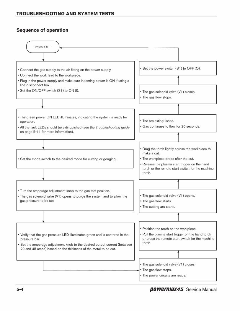
TroubleshooTing and sysTem TesTs
5-4 powermax45 Service Manual
Sequence of operation
Power OFF
•Connect the gas supply to the air fitting on the power supply.•Connect the work lead to the workpiece.•Plug in the power supply and make sure incoming power is ON if using a
line-disconnect box.•Set the ON/OFF switch (S1) to ON (I).
•Set the power switch (S1) to OFF (O).
•The gas solenoid valve (V1) closes.•The gas flow stops.
•The arc extinguishes.•Gas continues to flow for 20 seconds.
•Drag the torch lightly across the workpiece to make a cut.
•The workpiece drops after the cut.•Release the plasma start trigger on the hand
torch or the remote start switch for the machine torch.
•The gas solenoid valve (V1) opens.•The gas flow starts.•The cutting arc starts.
•Position the torch on the workpiece.•Pull the plasma start trigger on the hand torch
or press the remote start switch for the machine torch.
•The gas solenoid valve (V1) closes.•The gas flow stops.•The power circuits are ready.
•Turn the amperage adjustment knob to the gas test position.•The gas solenoid valve (V1) opens to purge the system and to allow the
gas pressure to be set.
•The green power ON LED illuminates, indicating the system is ready for operation.
•All the fault LEDs should be extinguished (see the Troubleshooting guide on page 5-11 for more information).
•Verify that the gas pressure LED illuminates green and is centered in the pressure bar.
•Set the amperage adjustment knob to the desired output current (between 20 and 45 amps) based on the thickness of the metal to be cut.
•Set the mode switch to the desired mode for cutting or gouging.
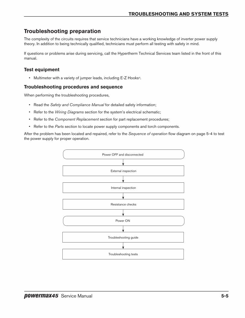
TroubleshooTing and sysTem TesTs
powermax45 Service Manual 5-5
Troubleshooting preparationThe complexity of the circuits requires that service technicians have a working knowledge of inverter power supply theory. In addition to being technically qualified, technicians must perform all testing with safety in mind.
If questions or problems arise during servicing, call the Hypertherm Technical Services team listed in the front of this manual.
Test equipment
• Multimeter with a variety of jumper leads, including E-Z Hooks®.
Troubleshooting procedures and sequence
When performing the troubleshooting procedures,
• Read the Safety and Compliance Manual for detailed safety information;
• Refer to the Wiring Diagrams section for the system’s electrical schematic;
• Refer to the Component Replacement section for part replacement procedures;
• Refer to the Parts section to locate power supply components and torch components.
After the problem has been located and repaired, refer to the Sequence of operation flow diagram on page 5-4 to test the power supply for proper operation.
External inspection
Power ON
Internal inspection
Resistance checks
Troubleshooting guide
Troubleshooting tests
Power OFF and disconnected

TroubleshooTing and sysTem TesTs
5-6 powermax45 Service Manual
dANgeR
ELECTRIC SHOCK CAN KILL
• Turn off the power and remove the input power plug from its receptacle before removing the cover from the power supply. If the power supply is connected directly to a line disconnect box, switch the line disconnect to off (o). In the U.S., use a “lock-out / tag-out” procedure until the service or maintenance work is complete. In other countries, follow appropriate national or local safety procedures.
• Do not touch live electrical parts! If power is required for servicing, use extreme caution when working near live electrical circuits. dangerous voltages exist inside the power supply that can cause serious injury or death.
• Do not attempt to repair the power board or control board. Do not cut away or remove any protective conformal coating from either board. To do so will risk a short circuit between the AC input circuit and the output circuit and may result in serious injury or death.
HoT PARTS CAN CAUSe SeVeRe bURNS
• Allow the power supply to cool before servicing.
MoVINg blAdeS CAN CAUSe INJURy
• Keep hands away from moving parts.
STATIC eleCTRICITy CAN dAMAge CIRCUIT boARdS
• Put on a grounded wrist strap before handling PC boards.
external inspection
1. Inspect the exterior of the power supply for damage to the cover and external components, such as the power cord and plug.
2. Inspect the torch and the torch lead for damage.
Internal inspection
1. Turn OFF the power, disconnect the power cord, and disconnect the gas supply.
2. Use a #2 Phillips screwdriver to remove the 2 screws from the handle on the top of the power supply. Gently pull on the end panel nearest the screw you are removing to keep pressure on the screw. When the screw is almost out, tilt the screwdriver slightly to help pull the screw out of the recessed hole.
3. Tip the end panels back slightly so that you can get the edges of the handle out from underneath them. Set the handle and screws aside. Continue to tilt the end panels outward to release the fan side of the cover from its track. Then lift the cover off the power supply.
TroubleshooTing and sysTem TesTs
powermax45 Service Manual 5-7
4. Remove the Mylar barrier from the power board side of the power supply. Be certain to replace the barrier when you are finished working on the power supply.
5. Inspect the inside of the power supply, especially on the side with the power board. Look for broken or loose wiring connections, burn and char marks, damaged components, and so on. Repair or replace as necessary.
Initial resistance checkAll resistance values must be taken with the power cord disconnected and all internal power supply wires attached. Perform the steps in Internal inspection on page 5-6 before continuing in this section.
• If resistance values are not close (±25%) to the values given in this section, isolate the problem by removing wires attached to the resistance check points or component until the problem is found.
• After the problem has been located and repaired, refer to the Sequence of operation flow diagram on page 5-4 to test the power supply for proper operation.
1. With the power disconnected and the torch removed from the power supply, set the ON/OFF switch (S1) to ON (I).
2. Check the resistance across the input leads (the leads are identified with “AC” printed on the power board).
• 200–240 V CSA and 230 V CE: resistance across the input leads = 75 kΩ.
• 400 V CE and 480 V CSA: resistance across the input leads = 2.5 MΩ.
3. Check the resistance from the input leads to ground to verify that it reads as open. For all power supplies, the resistance from input to ground should read as > 20 MΩ.
Note: With the power disconnected and the ON/OFF switch (S1) set to OFF (O), all circuits should read as open.
The electrical values shown are ±25%.
4. Check the output resistance for the values shown in the following table.
Measure resistance from200–240 V CSA and
230 V Ce power board location
400 V Ce and 480 V CSA power board
location
Approximate values
Work lead to nozzle J21 to J17 J21 to J16 100 kΩ
Work lead to electrode J21 to J19 J21 to J18 20 kΩ
Electrode to nozzle J19 to J17 J18 to J16 120 kΩ
Output to ground > 20 MΩ
If no problems were found during the visual inspection or the initial resistance check, and the power supply still does not operate correctly, see the Troubleshooting guide on page 5-11.
Note: The Troubleshooting guide provides most probable causes and solutions. Study the system wiring diagram and understand the theory of operation before troubleshooting. Before purchasing any major replacement component, verify the problem with Hypertherm Technical Service or the nearest Hypertherm repair facility.

TroubleshooTing and sysTem TesTs
5-8 powermax45 Service Manual
TP 19W
-+ -+
TP 18R
TP 17B
192 VDC 192 VDC
Power switch (S1)Power board (PCB2)
Control board (PCB1) Flyback circuit PE (ground)
Newer power boardInput diode bridge
(D48)Output diode and pilot arc
IGBT module (D38)
PFC IGBT (Q2)Inverter IGBT
(Q3)Work lead connection (J21) Test points
200–240 V CSA and 230 V Ce power supply overview
TP 19W
-+ -+
TP 18R
TP 17B
192 VDC 192 VDC
older power boardInput diode bridges
(D29, D39)
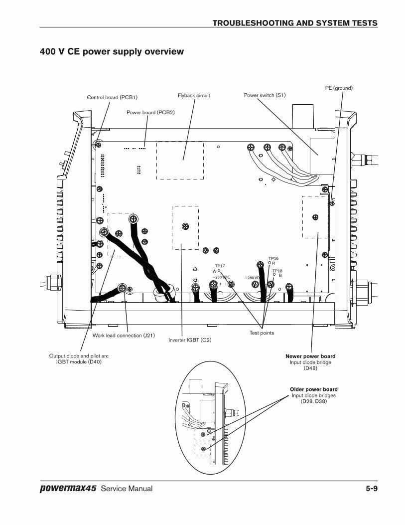
TroubleshooTing and sysTem TesTs
powermax45 Service Manual 5-9
TP17W
+ - + -
TP18B
TP16R
~280 VDC~280 VDC
400 V Ce power supply overview
Power switch (S1)
Power board (PCB2)
Control board (PCB1) Flyback circuitPE (ground)
Output diode and pilot arc IGBT module (D40)
Inverter IGBT (Q2)Work lead connection (J21)
Newer power boardInput diode bridge
(D48)
Test points
TP17W
+ - + -
TP18B
TP16R
~280 VDC~280 VDC
older power boardInput diode bridges
(D28, D38)
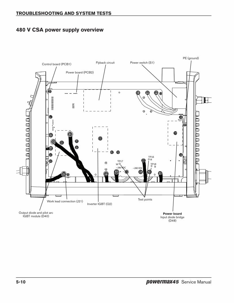
TroubleshooTing and sysTem TesTs
5-10 powermax45 Service Manual
TP17W
+ - + -
TP18B
TP16R
~280 VDC~280 VDC
480 V CSA power supply overview
Power switch (S1)
Power board (PCB2)
Control board (PCB1) Flyback circuitPE (ground)
Output diode and pilot arc IGBT module (D40)
Inverter IGBT (Q2)Work lead connection (J21)
Power boardInput diode bridge
(D48)
Test points

TroubleshooTing and sysTem TesTs
powermax45 Service Manual 5-11
Troubleshooting guideSee System tests on page 5-18 for detailed test procedures.
It is important to note, when troubleshooting a problem on the Powermax45, how the front panel LEDs operate. To help diagnose transient problems, an illuminated or blinking LED, including the bottom bar on the gas pressure bar, may continue to illuminate or blink for 10 to 20 seconds after the system is powered OFF. Once the system is powered ON, the LED should not illuminate or blink if the fault has been cleared.
Also, note that there is no static gas pressure reading. So the gas pressure LEDs may not indicate a low pressure situation if the gas was not connected when the system was powered ON. Attempting to fire the torch without the gas connected will cause the bottom yellow gas pressure LED to blink.
Problem This may mean Cause Solution
The ON/OFF power switch is set to ON (I), but the power ON LED is not illuminated.
There is insufficient voltage to the control circuits or a short-circuited power component.
•The system has no incoming voltage or an improper incoming voltage.
•The power board is faulty.
•Check to see that the system is plugged into an appropriately-sized circuit and that the circuit breaker has not been tripped.
•Perform Test 1 – voltage input on page 5-18 to check the incoming voltage and the power switch.
The power ON LED is illuminated, the fault LED is illuminated, and the bottom LED on the gas pressure bar is illuminated yellow and is blinking.
There is insufficient gas pressure to the machine.
•There is no gas attached to the system.
•The gas supply line has a restriction or the air filter element is dirty.
•The reading at the pressure transducer is below the minimum acceptable gas pressure.
•Ensure that the gas supply is connected correctly.
•Check the gas supply line for restrictions or damage.
•Check the air filter element and replace it if necessary.
•Perform Test 9 – pressure transducer on page 5-28 to verify that the pressure transducer functions correctly.
AC
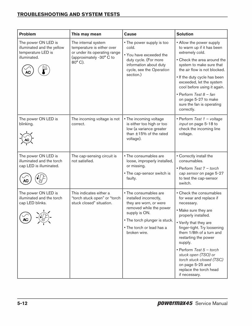
TroubleshooTing and sysTem TesTs
5-12 powermax45 Service Manual
Problem This may mean Cause Solution
The power ON LED is illuminated and the yellow temperature LED is illuminated.
The internal system temperature is either over or under its operating range (approximately -30° C to 80° C).
•The power supply is too cold.
•You have exceeded the duty cycle. (For more information about duty cycle, see the Operation section.)
•Allow the power supply to warm up if it has been extremely cold.
•Check the area around the system to make sure that the air flow is not blocked.
•If the duty cycle has been exceeded, let the system cool before using it again.
•Perform Test 8 – fan on page 5-27 to make sure the fan is operating correctly.
The power ON LED is blinking.
The incoming voltage is not correct.
•The incoming voltage is either too high or too low (a variance greater than ±15% of the rated voltage).
•Perform Test 1 – voltage input on page 5-18 to check the incoming line voltage.
The power ON LED is illuminated and the torch cap LED is illuminated.
The cap-sensing circuit is not satisfied.
•The consumables are loose, improperly installed, or missing.
•The cap-sensor switch is faulty.
•Correctly install the consumables.
•Perform Test 7 – torch cap sensor on page 5-27 to test the cap-sensor switch.
The power ON LED is illuminated and the torch cap LED blinks.
This indicates either a “torch stuck open” or “torch stuck closed” situation.
•The consumables are installed incorrectly, they are worn, or were removed while the power supply is ON.
•The torch plunger is stuck.
•The torch or lead has a broken wire.
•Check the consumables for wear and replace if necessary.
•Make sure they are properly installed.
•Verify that they are finger-tight. Try loosening them 1/8th of a turn and restarting the power supply.
•Perform Test 5 – torch stuck open (TSO) or torch stuck closed (TSC) on page 5-25 and replace the torch head if necessary.
AC
AC
AC
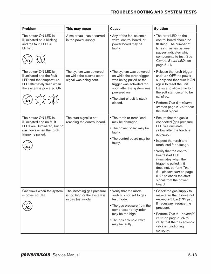
TroubleshooTing and sysTem TesTs
powermax45 Service Manual 5-13
Problem This may mean Cause Solution
The power ON LED is illuminated or is blinking and the fault LED is blinking.
A major fault has occurred in the power supply.
•Any of the fan, solenoid valve, control board, or power board may be faulty.
•The error LED on the control board should be flashing. The number of times it flashes between pauses indicates which components to test. See Control Board LEDs on page 5-16.
The power ON LED is illuminated and the fault LED and the temperature LED alternately flash when the system is powered ON.
The system was powered on while the plasma start signal was being sent.
•The system was powered on while the torch trigger was being pulled or the trigger was activated too soon after the system was powered on.
•The start circuit is stuck closed.
•Release the torch trigger and turn OFF the power supply and then turn it ON again to reset the unit. Be sure to allow time for the soft start circuit to be satisfied.
•Perform Test 6 – plasma start on page 5-26 to test the start signal.
The power ON LED is illuminated and no fault LEDs are illuminated, but no gas flows when the torch trigger is pulled.
The start signal is not reaching the control board.
•The torch or torch lead may be damaged.
•The power board may be faulty.
•The control board may be faulty.
•Ensure that the gas is connected (gas pressure LED will illuminate yellow after the torch is activated).
•Inspect the torch and torch lead for damage.
•Verify that the control board start LED illuminates when the trigger is pulled. If it does not, perform Test 6 – plasma start on page 5-26 to check the start signal from the power board.
Gas flows when the system is powered ON.
The incoming gas pressure is too high or the system is in gas test mode.
•Verify that the mode switch is not set to gas test mode.
•The gas pressure from the compressor or cylinder may be too high.
•The gas solenoid valve may be faulty.
•Check the gas supply to make sure that it does not exceed 9.3 bar (135 psi). If necessary, reduce the pressure.
•Perform Test 4 – solenoid valve on page 5-24 to verify that the gas solenoid valve is functioning correctly.
AC
AC
AC
AC
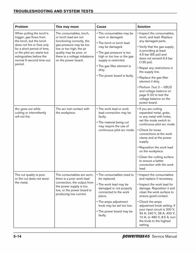
TroubleshooTing and sysTem TesTs
5-14 powermax45 Service Manual
Problem This may mean Cause Solution
When pulling the torch’s trigger, gas flows from the torch, but the torch does not fire or fires only for a short period of time, or the pilot arc starts but extinguishes before the normal 5-second time-out period.
The consumables, torch, or torch lead are not functioning correctly, the gas pressure may be too low or too high, the air quality may be poor, or there is a voltage imbalance on the power board.
•The consumables may be worn or damaged.
•The torch or torch lead may be damaged.
•The gas pressure is too high or too low or the gas supply is restricted.
•The gas filter element is dirty.
•The power board is faulty.
•Inspect the consumables, torch, and lead. Replace any damaged parts.
•Verify that the gas supply is providing at least 4.5 bar (65 psi) and does not exceed 9.3 bar (135 psi).
•Repair any restrictions in the supply line.
•Replace the gas filter element if dirty.
•Perform Test 3 – VBUS and voltage balance on page 5-20 to test the voltage balance on the power board.
Arc goes out while cutting or intermittently will not fire.
The arc lost contact with the workpiece.
•The work lead or work lead connection may be faulty.
•The material being cut may require the use of continuous pilot arc mode.
•If you are cutting expanded metal, grate, or any metal with holes, set the mode switch to continuous pilot arc mode.
•Check for loose connections at the work clamp and at the power supply.
•Reposition the work lead on the workpiece.
•Clean the cutting surface to ensure a better connection with the work lead.
The cut quality is poor or the cut does not sever the metal.
The consumables are worn, there is a poor work lead connection, the output from the power supply is too low, or the power board is producing low current.
•The consumables need to be replaced.
•The work lead may be damaged or not properly connected to the work piece.
•The amps adjustment knob may be set too low.
•The power board may be faulty.
•Inspect the consumables and replace if necessary.
•Inspect the work lead for damage. Reposition it and clean the work surface to ensure good contact.
•Check the amps adjustment knob setting. If your input circuit is 200 V, 34 A; 240 V, 28 A; 400 V, 10 A; or 480 V, 8.5 A, turn the knob to the highest setting.
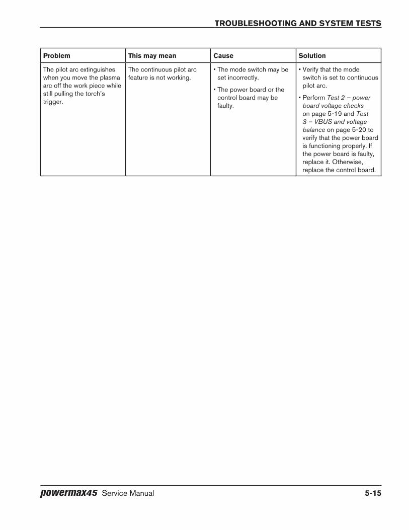
TroubleshooTing and sysTem TesTs
powermax45 Service Manual 5-15
Problem This may mean Cause Solution
The pilot arc extinguishes when you move the plasma arc off the work piece while still pulling the torch’s trigger.
The continuous pilot arc feature is not working.
•The mode switch may be set incorrectly.
•The power board or the control board may be faulty.
•Verify that the mode switch is set to continuous pilot arc.
•Perform Test 2 – power board voltage checks on page 5-19 and Test 3 – VBUS and voltage balance on page 5-20 to verify that the power board is functioning properly. If the power board is faulty, replace it. Otherwise, replace the control board.

TroubleshooTing and sysTem TesTs
5-16 powermax45 Service Manual
Control board ledsThe Powermax45 control board (PCB1) has 4 diagnostic LEDs.
The control board LEDs are:
• Start – The power supply has a start signal. This LED illuminates when the power supply receives a start signal and remains illuminated during normal operation.
• Transfer – This LED illuminates when there is proper arc transfer between the torch and the workpiece, and will flash during continuous pilot arc operation (such as when cutting expanded metal or moving the arc off the plate and then back on).
• Error – The Error LED illuminates whenever there is a fault in the system. If the Fault LED on the front panel flashes and the Error LED on the control board also flashes, there is a major fault in the system. The number of flashes between pauses indicates which component may have failed.
• Reset – This LED illuminates when the reset circuit is active or the watchdog circuit fires.
During normal operation, the power ON LED on the front of the power supply and the Start and Transfer LEDs on the control board illuminate. When a problem occurs with the system, one or more of the LEDs on the front of the power supply and the Error LED or the Reset LED on the control board may illuminate or flash.
Control board
Ribbon cable
Reset/watchdog
Error
Transfer (XFR)Start

TroubleshooTing and sysTem TesTs
powermax45 Service Manual 5-17
Use the control board error and Reset leds to troubleshoot
The Error and Reset LEDs provide information to use when troubleshooting a system failure. If the LEDs on the front of the power supply are flashing, look at the Error LED on the control board to determine where the fault may be. Count the number of flashes and then look at the table below to determine the corrective action.
Reset led
When the control board’s Reset LED illuminates, the voltages on the power board may be incorrect. Perform the following tests at J7 on 200–240 V CSA power supplies and 230 V CE power supplies or J8 on 400 V CE and 480 V CSA power supplies (the pin numbers are the same for all power supplies) on the power board (see Test 2 – power board voltage checks on page 5-19):
• Test pin 25 to ground for 3.3 VDC (±10%).
• Test pin 24 to ground for 5 VDC (±10%).
• Test pin 12 to ground for 2.2 VDC (±10%).
If the values you find are not within ±10% of the above values, detach the control board’s ribbon cable and perform the tests again. If you find the correct values the second time, replace the control board. Otherwise, replace the power board.
error led
The number of times the Error LED flashes indicates the problem detected. Each flash is a half-second long and each series of flashes is separated by a 2-second pause. See System tests on page 5-18 for detailed test procedures.
The following table shows the meaning associated with each set of flashes.
Number of error led flashes Problem indicated Solution
1 Faulty control board Replace the control board.
2 Faulty power board Replace the power board.
3 Either a faulty power board or a faulty control board
•Perform Test 3 – VBUS and voltage balance on page 5-20. If any of the values are incorrect, replace the power board.
•Perform Test 2 – power board voltage checks on page 5-19. If any of the values for pins 5, 7, or 12 are incorrect, remove the control board and test again. If the values are correct, replace the control board.
•When performing test 2, if the values for pins 5, 7, and 12 are correct, but any other values are incorrect, replace the power board.
4 Faulty gas solenoid valve Replace the gas solenoid valve.
5 Faulty fan Replace the fan.
6 Machine motion relay fault Replace the power board.

TroubleshooTing and sysTem TesTs
5-18 powermax45 Service Manual
System testsThere is a ground clip near the top of the rear end cap that can be used as ground for any tests that require the multimeter to be attached to ground. There is also a ground on the heat sink with access next to the power board and below the power switch.
WARNINg
Voltages of up to 50 VdC continue to be present on the dC bus for at least 30 seconds after disconnecting the input power. Allow bus voltages to dissipate before performing any tests.
Test 1 – voltage input
Check the incoming voltage and the line voltage to the top of the power switch (S1).
1. Disconnect the electrical power and set the ON/OFF switch to OFF (O).
2. Once you have your test leads in place, reconnect the electrical power. Leave the ON/OFF switch set to OFF. The voltage should equal the line voltage of the incoming circuit.
3. If the AC voltage is incorrect, check to see that you have power to the unit. If you do have power, check the power cord for damage.
4. With the electrical power connected, set the ON/OFF switch to ON (I), and measure the AC voltage from J1 to J2 (labeled “AC” on the power board). This value should be the same as the incoming line voltage. If it is not, check the ON/OFF switch.
5. If the power ON LED is still illuminated, perform Test 2 – power board voltage checks on page 5-19 to determine whether the power board or the control board is faulty.
Note: All values can be ±15%.
Ground wire clip
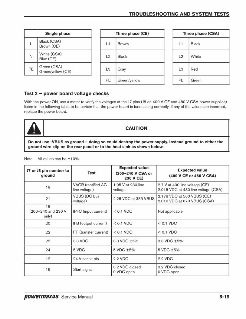
TroubleshooTing and sysTem TesTs
powermax45 Service Manual 5-19
Single phase Three phase (Ce) Three phase (CSA)
L Black (CSA)Brown (CE) L1 Brown L1 Black
N White (CSA)Blue (CE) L2 Black L2 White
PE Green (CSA)Green/yellow (CE) L3 Gray L3 Red
PE Green/yellow PE Green
Test 2 – power board voltage checks
With the power ON, use a meter to verify the voltages at the J7 pins (J8 on 400 V CE and 480 V CSA power supplies) listed in the following table to be certain that the power board is functioning correctly. If any of the values are incorrect, replace the power board.
CAUTIoN
do not use -VbUS as ground – doing so could destroy the power supply. Instead ground to either the ground wire clip on the rear panel or to the heat sink as shown below.
Note: All values can be ±10%.
J7 or J8 pin number to ground Test
expected value(200–240 V CSA or
230 V Ce)
expected value(400 V Ce or 480 V CSA)
19 VACR (rectified AC line voltage)
1.95 V at 230 line voltage
2.7 V at 400 line voltage (CE)2.016 VDC at 480 line voltage (CSA)
21 VBUS (DC bus voltage) 2.28 VDC at 385 VBUS 2.178 VDC at 560 VBUS (CE)
2.016 VDC at 670 VBUS (CSA)18
(200–240 and 230 V only)
IPFC (input current) < 0.1 VDC Not applicable
20 IFB (output current) < 0.1 VDC < 0.1 VDC
22 ITF (transfer current) < 0.1 VDC < 0.1 VDC
25 3.3 VDC 3.3 VDC ±5% 3.3 VDC ±5%
24 5 VDC 5 VDC ±5% 5 VDC ±5%
12 24 V sense pin 2.2 VDC 2.2 VDC
16 Start signal 3.2 VDC closed0 VDC open
3.2 VDC closed0 VDC open

TroubleshooTing and sysTem TesTs
5-20 powermax45 Service Manual
Note: To test the values at pin 16, you must have the torch and power supply positioned such that you can safely pull and release the torch’s trigger.
Test 3 – VbUS and voltage balance
Test the power board to ensure that the circuits are balanced. There are three procedures below. Use the first procedure if you have a 200–240 V CSA power supply or a 230 V CE power supply. Use the second procedure if you have a 400 V CE power supply. Use the third procedure if you have a 480 V CSA power supply.
For this test, you can use the test point loops or you can test on the capacitor screws. The test points are labeled on the back of the power board, as are the voltages and positive and negative capacitor terminals.
CAUTIoN
To test using the test points, do not use a multimeter with test probes. Use e-Z Hook leads instead and attach them to the test point loops.
J7 (200–240V CSA / 230V CE) J8 (400 V CE / 480V CSA)
122526
Ground to the ground wire clip or to the heat sink
TP 19W
-+ -+
TP 18R
TP 17B
192 VDC 192 VDC
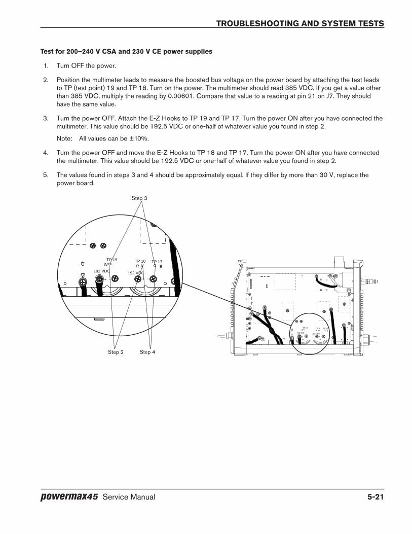
TroubleshooTing and sysTem TesTs
powermax45 Service Manual 5-21
Test for 200–240 V CSA and 230 V Ce power supplies
1. Turn OFF the power.
2. Position the multimeter leads to measure the boosted bus voltage on the power board by attaching the test leads to TP (test point) 19 and TP 18. Turn on the power. The multimeter should read 385 VDC. If you get a value other than 385 VDC, multiply the reading by 0.00601. Compare that value to a reading at pin 21 on J7. They should have the same value.
3. Turn the power OFF. Attach the E-Z Hooks to TP 19 and TP 17. Turn the power ON after you have connected the multimeter. This value should be 192.5 VDC or one-half of whatever value you found in step 2.
Note: All values can be ±10%.
4. Turn the power OFF and move the E-Z Hooks to TP 18 and TP 17. Turn the power ON after you have connected the multimeter. This value should be 192.5 VDC or one-half of whatever value you found in step 2.
5. The values found in steps 3 and 4 should be approximately equal. If they differ by more than 30 V, replace the power board.
TP 19W
-+ -+
TP 18R
TP 17B
192 VDC 192 VDC
TP 19W
-+ -+
TP 18R
TP 17B
192 VDC 192 VDC
Step 3
Step 4Step 2
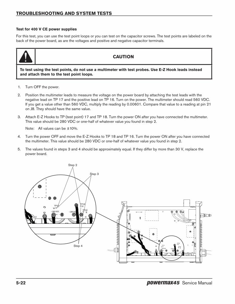
TroubleshooTing and sysTem TesTs
5-22 powermax45 Service Manual
Test for 400 V Ce power supplies
For this test, you can use the test point loops or you can test on the capacitor screws. The test points are labeled on the back of the power board, as are the voltages and positive and negative capacitor terminals.
CAUTIoN
To test using the test points, do not use a multimeter with test probes. Use e-Z Hook leads instead and attach them to the test point loops.
1. Turn OFF the power.
2. Position the multimeter leads to measure the voltage on the power board by attaching the test leads with the negative lead on TP 17 and the positive lead on TP 16. Turn on the power. The multimeter should read 560 VDC. If you get a value other than 560 VDC, multiply the reading by 0.00601. Compare that value to a reading at pin 21 on J8. They should have the same value.
3. Attach E-Z Hooks to TP (test point) 17 and TP 18. Turn the power ON after you have connected the multimeter. This value should be 280 VDC or one-half of whatever value you found in step 2.
Note: All values can be ±10%.
4. Turn the power OFF and move the E-Z Hooks to TP 18 and TP 16. Turn the power ON after you have connected the multimeter. This value should be 280 VDC or one-half of whatever value you found in step 2.
5. The values found in steps 3 and 4 should be approximately equal. If they differ by more than 30 V, replace the power board.
TP17W
+ - + -
TP18B
TP16R
~280 VDC~280 VDC
TP17W
+ - + -
TP18B
TP16R
~280 VDC ~280 VDC
Step 2
Step 4
Step 3
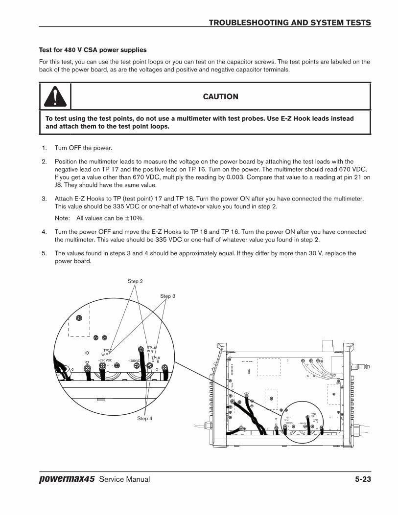
TroubleshooTing and sysTem TesTs
powermax45 Service Manual 5-23
Test for 480 V CSA power supplies
For this test, you can use the test point loops or you can test on the capacitor screws. The test points are labeled on the back of the power board, as are the voltages and positive and negative capacitor terminals.
CAUTIoN
To test using the test points, do not use a multimeter with test probes. Use e-Z Hook leads instead and attach them to the test point loops.
1. Turn OFF the power.
2. Position the multimeter leads to measure the voltage on the power board by attaching the test leads with the negative lead on TP 17 and the positive lead on TP 16. Turn on the power. The multimeter should read 670 VDC. If you get a value other than 670 VDC, multiply the reading by 0.003. Compare that value to a reading at pin 21 on J8. They should have the same value.
3. Attach E-Z Hooks to TP (test point) 17 and TP 18. Turn the power ON after you have connected the multimeter. This value should be 335 VDC or one-half of whatever value you found in step 2.
Note: All values can be ±10%.
4. Turn the power OFF and move the E-Z Hooks to TP 18 and TP 16. Turn the power ON after you have connected the multimeter. This value should be 335 VDC or one-half of whatever value you found in step 2.
5. The values found in steps 3 and 4 should be approximately equal. If they differ by more than 30 V, replace the power board.
TP17W
+ - + -
TP18B
TP16R
~280 VDC~280 VDC
TP17W
+ - + -
TP18B
TP16R
~280 VDC ~280 VDC
Step 2
Step 4
Step 3

TroubleshooTing and sysTem TesTs
5-24 powermax45 Service Manual
Test 4 – solenoid valve
If gas is not flowing properly, test the solenoid valve for proper operation.
1. There is an LED on the solenoid valve that illuminates red when the torch is fired or when the amperage control knob is set to gas text mode. It stays illuminated until postflow stops. Turn the amperage knob to gas test and verify that the LED illuminates.
2. Place a jumper from pin 4 of J3 (J4 for 400 V CE and 480 V CSA power supplies) on the power board to ground. You should hear the valve click.
3. If you do not hear the valve click or the LED does not illuminate and a voltage check on pin 4 of J3 (or J4) reads 24 VDC, replace the solenoid valve.
TP 19W
-+ -+
TP 18R
TP 17B
192 VDC 192 VDC
Solenoid valve LED
J3 or J4
PE (ground)
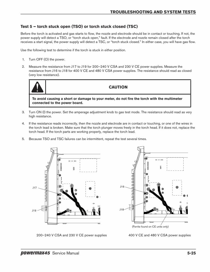
TroubleshooTing and sysTem TesTs
powermax45 Service Manual 5-25
Test 5 – torch stuck open (TSo) or torch stuck closed (TSC)
Before the torch is activated and gas starts to flow, the nozzle and electrode should be in contact or touching. If not, the power supply will detect a TSO, or “torch stuck open,” fault. If the electrode and nozzle remain closed after the torch receives a start signal, the power supply will detect a TSC, or “torch stuck closed.” In either case, you will have gas flow.
Use the following test to determine if the torch is stuck in either position.
1. Turn OFF (O) the power.
2. Measure the resistance from J17 to J19 for 200–240 V CSA and 230 V CE power supplies. Measure the resistance from J16 to J18 for 400 V CE and 480 V CSA power supplies. The resistance should read as closed (very low resistance).
CAUTIoN
To avoid causing a short or damage to your meter, do not fire the torch with the multimeter connected to the power board.
3. Turn ON (I) the power. Set the amperage adjustment knob to gas test mode. The resistance should read as very high resistance.
4. If the resistance reads incorrectly, then the nozzle and electrode are in contact or touching, or one of the wires in the torch lead is broken. Make sure that the torch plunger moves freely in the torch head. If it does not, replace the torch head. If the torch parts are working properly, replace the torch lead.
5. Because TSO and TSC failures can be intermittent, repeat the test several times.
TP 19W
-+ -+
TP 18R
TP 17B
192 VDC 192 VDC
200–240 V CSA and 230 V CE power supplies
J17
J19
TP17W
+ - + -
TP18B
TP16R
~280 VDC~280 VDC
J16
J18
400 V CE and 480 V CSA power supplies
(Ferrite found on CE units only)

TroubleshooTing and sysTem TesTs
5-26 powermax45 Service Manual
Test 6 – plasma start
Verify that the control board LED is receiving a valid start signal.
1. With the power ON, look at the Start LED on the control board. It should illuminate whenever the torch is activated.
2. Set the ON/OFF switch to OFF (O). Check the resistance between pins 2 and 3 of J10 on the power board. With the trigger or start signal engaged, the resistance should be 10 Ω or less. With the trigger or start signal disengaged, the circuit should read as approximately 3 kΩ. If this test fails, check the torch’s start switch and the torch wires.
NOTE: If the torch will not fire after completing this test, verify that J10 is connected properly – that the pins are not offset and the connector is not backwards.
3. Set the ON/OFF switch to ON (I). Measure pin 16 of J7 (or J8 for 400 V CE and 480 V CSA power supplies) to ground (see Test 2 – power board voltage checks on page 5-19). It should measure as 0 VDC for an open circuit or 3.2 VDC for a closed circuit. If the values are not correct, replace the power board.
CAUTIoN
While testing, remove the consumables to avoid accidentally firing the torch.
TP 19W
-+ -+
TP 18R
TP 17B
192 VDC 192 VDC
J10
J7 (or J8)J10

TroubleshooTing and sysTem TesTs
powermax45 Service Manual 5-27
Test 7 – torch cap sensor
Test the cap-sensor switch and torch leads.
1. Set the ON/OFF switch to OFF (O).
2. Measure the resistance between pins 1 and 2 of J10 on the power board. It should measure less than 10 Ω. If it reads as open, the cap-sensor switch circuit is not satisfied.
3. If the torch plunger moves smoothly and the consumables are correctly installed, then either the cap-sensor switch is faulty or the torch lead has a broken wire. Replace the faulty part.
Test 8 – fan
Test the fan for proper operation.
• Place a jumper from pin 1 of J3 to pin 1 of J4 on 200–240 V CSA power supplies and 230 V CE power supplies or from pin 1 of J4 to pin 1 of J5 on 400 V CE and 480 V CSA power supplies. If the fan does not operate, replace the fan.
NOTE: Testing the fan can trigger a fault due to protection features on the fan driver chip. You can disregard this fault if it occurs as a result of a fan test. The purpose of the fan test is to ensure the fan is operating properly, not to test the fan drive circuit.
TP 19W
-+ -+
TP 18R
TP 17B
192 VDC 192 VDC
TP17W
+ - + -
TP18B
TP16R
~280 VDC~280 VDC
J3 and J4 J4 and J5
200–240 V CSA and 230 V CE power supplies
400 V CE and 480 V CSA power supplies
(Ferrite found on CE units only)
TroubleshooTing and sysTem TesTs
5-28 powermax45 Service Manual
Test 9 – pressure transducer
Test the pressure transducer to ensure that the system is receiving the proper gas pressure.
1. Turn ON the power.
2. Check the voltage between pins 1 and 2 of J5 for 200–240 V CSA and 230 V CE power supplies or pins 1 and 2 of J6 for 400 V CE and 480 V CSA power supplies. It should read approximately 0.2 V if there is no gas pressure. If the gas pressure is within system tolerances, the circuit should read approximately 3.3 V.
The minimum acceptable gas pressure varies by torch type, torch lead length, and mode switch setting as shown in the following table.
Normal Continuous pilot arc gouging
Handheld, 6.1 m (20 feet) 3.45 bar (50 psi) 3.45 bar (50 psi) 1.72 bar (25 psi)
Handheld, 15.24 m (50 feet) 3.80 bar (55 psi) 3.80 bar (55 psi) 2.07 bar (30 psi)
Mechanized, 7.62 m (25 feet) 3.45 bar (50 psi) 3.45 bar (50 psi) 1.72 bar (25 psi)
Mechanized, 10.7 m (35 feet) 3.45 bar (55 psi) 3.45 bar (50 psi) 1.72 bar (25 psi)
Mechanized, 15.25 m (50 feet) 3.80 bar (55 psi) 3.80 bar (55 psi) 2.07 bar (30 psi)
Test 10 – power switch trip coil
The 200 –240 V CSA and the 230 V CE power supplies have over-voltage protection on the power switch in the form of a mechanical trip coil. If voltage provided by the incoming circuit is greater than the maximum voltage, the trip coil will switch OFF the power supply.
If the power supply appears to be shutting down unexpectedly, test the power switch:
1. With the power switch in the OFF position, disconnect the electrical power.
2. Move the power switch to the ON position. If the switch stays in position, the trip coil mechanism is functioning properly. If it does not stay in the ON position, replace the power switch.

powermax45 Service Manual 6-1
Section 6
CoMPoNeNT RePlACeMeNT
In this section:
Remove and replace the cover and Mylar® barrier .............................................................................................................................6-2Removal .............................................................................................................................................................................................6-2Replacement .....................................................................................................................................................................................6-3
Replace the work lead (CSA and CE) ..................................................................................................................................................6-3Replace the power cord (200–240 V CSA) .......................................................................................................................................6-5Replace the power cord (230 V CE) ....................................................................................................................................................6-6Replace the power cord (400 V CE) ....................................................................................................................................................6-8Replace the power cord (480 V CSA) .............................................................................................................................................. 6-10Replace the fan .......................................................................................................................................................................................6-12Replace the gas filter element .............................................................................................................................................................6-13Replace the air filter and regulator ......................................................................................................................................................6-15Replace the control board ....................................................................................................................................................................6-16Replace the power board (200–240 V CSA and 230 V CE) ..................................................................................................... 6-17Replace the power board (400 V CE and 480 V CSA) ...............................................................................................................6-21
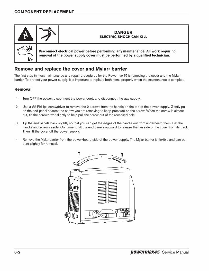
Component replaCement
6-2 powermax45 Service Manual
dANgeRELECTRIC SHOCK CAN KILL
disconnect electrical power before performing any maintenance. All work requiring removal of the power supply cover must be performed by a qualified technician.
Remove and replace the cover and Mylar® barrierThe first step in most maintenance and repair procedures for the Powermax45 is removing the cover and the Mylar barrier. To protect your power supply, it is important to replace both items properly when the maintenance is complete.
Removal
1. Turn OFF the power, disconnect the power cord, and disconnect the gas supply.
2. Use a #2 Phillips screwdriver to remove the 2 screws from the handle on the top of the power supply. Gently pull on the end panel nearest the screw you are removing to keep pressure on the screw. When the screw is almost out, tilt the screwdriver slightly to help pull the screw out of the recessed hole.
3. Tip the end panels back slightly so that you can get the edges of the handle out from underneath them. Set the handle and screws aside. Continue to tilt the end panels outward to release the fan side of the cover from its track. Then lift the cover off the power supply.
4. Remove the Mylar barrier from the power-board side of the power supply. The Mylar barrier is flexible and can be bent slightly for removal.
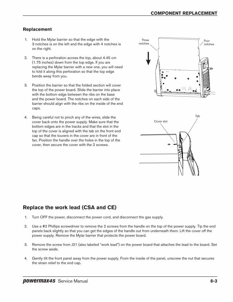
component replacement
powermax45 Service Manual 6-3
Replacement
1. Hold the Mylar barrier so that the edge with the 3 notches is on the left and the edge with 4 notches is on the right.
2. There is a perforation across the top, about 4.45 cm (1.75 inches) down from the top edge. If you are replacing the Mylar barrier with a new one, you will need to fold it along this perforation so that the top edge bends away from you.
3. Position the barrier so that the folded section will cover the top of the power board. Slide the barrier into place with the bottom edge between the ribs on the base and the power board. The notches on each side of the barrier should align with the ribs on the inside of the end caps.
4. Being careful not to pinch any of the wires, slide the cover back onto the power supply. Make sure that the bottom edges are in the tracks and that the slot in the top of the cover is aligned with the tab on the front end cap so that the louvers in the cover are in front of the fan. Position the handle over the holes in the top of the cover, then secure the cover with the 2 screws.
Three notches
Cover slot
Tab
Four notches
Replace the work lead (CSA and Ce)
1. Turn OFF the power, disconnect the power cord, and disconnect the gas supply.
2. Use a #2 Phillips screwdriver to remove the 2 screws from the handle on the top of the power supply. Tip the end panels back slightly so that you can get the edges of the handle out from underneath them. Lift the cover off the power supply. Remove the Mylar barrier that protects the power board.
3. Remove the screw from J21 (also labeled “work lead”) on the power board that attaches the lead to the board. Set the screw aside.
4. Gently tilt the front panel away from the power supply. From the inside of the panel, unscrew the nut that secures the strain relief to the end cap.
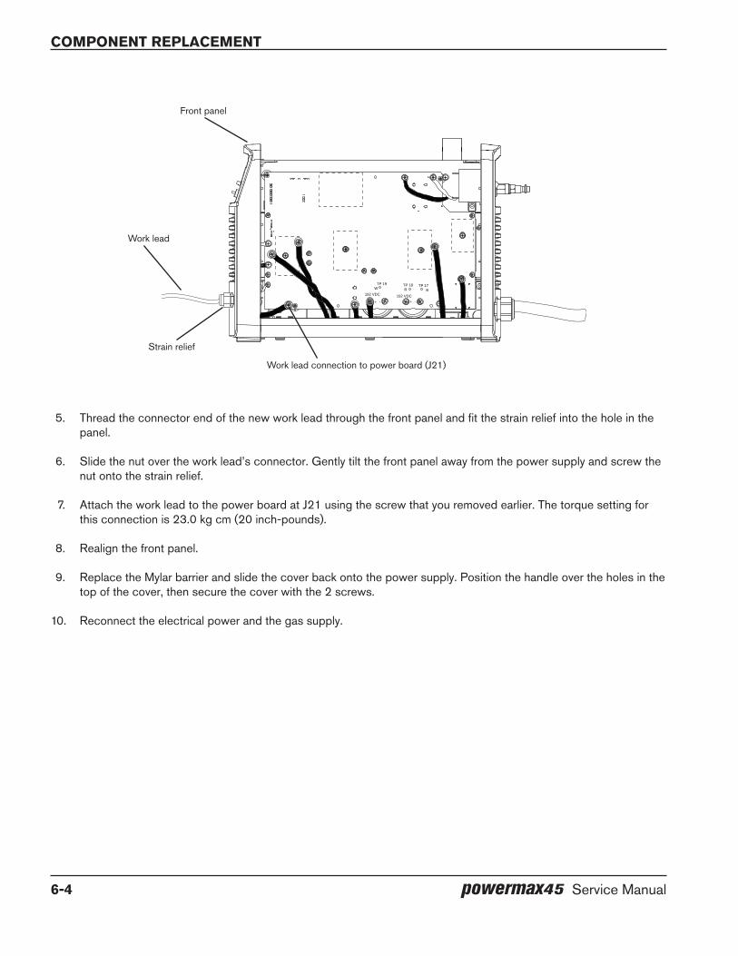
Component replaCement
6-4 powermax45 Service Manual
5. Thread the connector end of the new work lead through the front panel and fit the strain relief into the hole in the panel.
6. Slide the nut over the work lead’s connector. Gently tilt the front panel away from the power supply and screw the nut onto the strain relief.
7. Attach the work lead to the power board at J21 using the screw that you removed earlier. The torque setting for this connection is 23.0 kg cm (20 inch-pounds).
8. Realign the front panel.
9. Replace the Mylar barrier and slide the cover back onto the power supply. Position the handle over the holes in the top of the cover, then secure the cover with the 2 screws.
10. Reconnect the electrical power and the gas supply.
TP 19W
-+ -+
TP 18R
TP 17B
192 VDC 192 VDC
Work lead
Work lead connection to power board (J21)
Front panel
Strain relief

component replacement
powermax45 Service Manual 6-5
Replace the power cord (200–240 V CSA)
1. Turn OFF the power, disconnect the power cord, and disconnect the gas supply.
2. Use a #2 Phillips screwdriver to remove the 2 screws from the handle on the top of the power supply. Tip the end panels back slightly so that you can get the edges of the handle out from underneath them. Lift the cover off the power supply. Remove the Mylar barrier that protects the power board.
The 200–240 V CSA power cord has a black wire and a white wire that connect to the power switch, and a green ground wire that connects to the heat sink.
3. Remove the rear end panel or gently tilt it away from the power supply until you can access the screws that secure the power cord wires to the back of the power switch.
NOTE: To remove the rear end panel, you must first remove the air fitting.
4. Remove the screws that secure the connectors for the white and black wires from the power switch to disconnect them.
5. Remove the screw that holds the green wire to the heat sink.
6. On the outside of the power supply, loosen the power cord’s strain relief retention nut so that the wires move freely. If you will replace the strain relief, use an adjustable wrench to unscrew the strain relief nut on the inside of the power supply to remove the old strain relief.
7. From the outside of the power supply, pull the old power cord through the strain relief or through the hole in the rear end panel to remove it.
lBlack wire (CSA)
NWhite wire (CSA)
Single phase (CSA)
L Black
N White
PE Green
TP 19W
-+ -+
TP 18R
TP 17B
192 VDC 192 VDC

Component replaCement
6-6 powermax45 Service Manual
8. If you are replacing the old strain relief with the new strain relief contained in the kit, slide the new strain relief onto the new power cord and route the wires for the new power cord through the hole in the end panel. Slide the new strain relief nut over the wires and screw it to the strain relief from the inside of the end panel. Hand tighten the nut and then over-tighten slightly more.
If you are keeping the old strain relief in place, route the wires for the new power cord through the strain relief.
9. Screw the connector for the black wire onto the pin on the upper left side of the power switch with a torque setting of 23.0 kg cm (20 inch-pounds).
10. Screw the connector for the white wire onto the pin on the upper right side of the power switch with a torque setting of 23.0 kg cm (20 inch-pounds).
11. Tighten the green ground wire to the heat sink with a torque setting of 17.3 kg cm (15 inch-pounds).
12. Position the wires in the wire chase up the side of the end panel and out of the way of the power board.
13. Replace or reposition the end panel. Make sure that the screw hole in the ground clip aligns with the screw holes in the end panel and the power supply.
14. Tighten the strain relief’s retention nut on the outside of the end panel to secure the new power cord.
15. Being careful not to pinch any of the wires, replace the Mylar barrier and slide the cover back onto the power supply. Position the handle over the holes in the top of the cover, then use the 2 screws to secure the cover.
16. Reconnect the electrical power and the gas supply.
Replace the power cord (230 V Ce)
1. Turn OFF the power, disconnect the power cord, and disconnect the gas supply.
2. Use a #2 Phillips screwdriver to remove the 2 screws from the handle on the top of the power supply. Tip the end panels back slightly so that you can get the edges of the handle out from underneath them. Lift the cover off the power supply. Remove the Mylar barrier that protects the power board.
The 230 V CE power cord has a brown wire and a blue wire that connect to the power switch, and a green/yellow ground wire that connects to the heat sink.
3. Remove the rear end panel or gently tilt it away from the power supply until you can access the screws that secure the power cord wires to the back of the power switch.
NOTE: To remove the rear end panel, you must first remove the air fitting.
4. Remove the screws that secure the connectors for the blue and brown wires from the power switch to disconnect them.
5. Remove the screw that holds the green/yellow wire to the heat sink.

component replacement
powermax45 Service Manual 6-7
6. On the outside of the power supply, loosen the power cord’s strain relief retention nut so that the wires move freely.
7. From the inside of the power supply, pull the wires through the strain relief and the hole in the rear end panel to remove the old power cord.
8. If you are replacing the old strain relief with the new strain relief contained in the kit:
a. Use an adjustable wrench to unscrew the strain relief nut on the inside of the power supply to remove the old strain relief.
b. Slide the new strain relief through the hole in the rear end panel of the power supply.
c. Secure the strain relief on the inside of the power supply using the new strain relief nut. Hand tighten the nut and then over-tighten slightly more.
9. From the inside of the power supply, route the wires of the new power cord through the strain relief in the rear end panel. Do not remove the tubular ferrite bead from the power switch end of the brown and blue wires. (Because the CE power cord includes the ferrite bead, you cannot route the power cord through the strain relief from the outside of the power supply.)
10. Slide the strain relief retention nut over the wires of the new power cord and slide the retention nut forward toward the power supply.
11. Screw the connector for the brown wire onto the pin on the upper left side of the power switch with a torque setting of 23.0 kg cm (20 inch-pounds).
lBrown wire (CE)
NBlue wire (CE)
Single phase (Ce)
L Brown
N Blue
PE Green/yellow
TP 19W
-+ -+
TP 18R
TP 17B
192 VDC 192 VDC
Component replaCement
6-8 powermax45 Service Manual
12. Screw the connector for the blue wire onto the pin on the upper right side of the power switch with a torque setting of 23.0 kg cm (20 inch-pounds).
13. Tighten the green/yellow ground wire to the heat sink with a torque setting of 17.3 kg cm (15 inch-pounds).
14. Position the wires in the wire chase up the side of the end panel and out of the way of the power board.
15. Replace or reposition the end panel. Make sure that the screw hole in the ground clip aligns with the screw holes in the end panel and the power supply.
16. Tighten the strain relief’s retention nut on the outside of the end panel to secure the new power cord.
17. If you are installing a plug on the new power cord, use a plug that meets national and local electrical codes. The plug must be connected to the power cord by a licensed electrician.
18. Being careful not to pinch any of the wires, replace the Mylar barrier and slide the cover back onto the power supply. Position the handle over the holes in the top of the cover, then use the 2 screws to secure the cover.
19. Reconnect the electrical power and the gas supply.
Replace the power cord (400 V Ce)
1. Turn OFF the power, disconnect the power cord, and disconnect the gas supply.
2. Use a #2 Phillips screwdriver to remove the 2 screws from the handle on the top of the power supply. Tip the end panels back slightly so that you can get the edges of the handle out from underneath them. Lift the cover off the power supply. Remove the Mylar barrier that protects the power board.
The 400 V CE power cord has 3 wires – brown, black, and gray – that connect to the power switch and a green/yellow ground wire that connects to the heat sink.
3. Remove the rear end panel or gently tilt it away from the power supply until you can access the screws that secure the power cord wires to the back of the power switch.
NOTE: To remove the rear end panel, you must first remove the air fitting.
4. Remove the 3 screws that secure the power cord wires to the power switch and gently pull the wires out of the switch.
5. Remove the screw that holds the green/yellow ground wire to the heat sink.

component replacement
powermax45 Service Manual 6-9
6. On the outside of the power supply, loosen the strain relief retention nut so that the wires move freely.
7. From the inside of the power supply, pull the wires through the strain relief and the hole in the end panel to remove the old power cord.
8. If you are replacing the old strain relief with the new strain relief contained in the kit:
a. Use an adjustable wrench to unscrew the strain relief nut on the inside of the power supply to remove the old strain relief.
b. Slide the new strain relief through the hole in the rear end panel of the power supply.
c. Secure the strain relief on the inside of the power supply using the new strain relief nut. Hand tighten the nut and then over-tighten slightly more.
9. From the inside of the power supply, route the wires of the new power cord through the strain relief in the rear end panel. Do not remove the tubular ferrite bead from the power switch end of the brown, black, and gray wires. (Because the CE power cord includes the ferrite bead, you cannot route the power cord through the strain relief from the outside of the power supply.)
10. Slide the strain relief retention nut over the wires of the new power cord and slide the retention nut forward toward the power supply.
TP17W
+ - + -
TP18B
TP16R
~280 VDC~280 VDC
L1 L2 L3 Three phase (Ce)
L1 Brown
L2 Black
L3 Gray
PE Green/yellow

Component replaCement
6-10 powermax45 Service Manual
11. Press the connector for the brown wire into the hole on the top left side of the power switch (L1) and replace the screw that secures it. Torque the screw to 11.5 kg cm (10 inch-pounds).
12. Press the connector for the black wire into the hole on the top middle of the power switch (L2) and replace the screw that secures it. Torque the screw to 11.5 kg cm (10 inch-pounds).
13. Press the connector for the gray wire into the hole on the top right of the power switch (L3) and replace the screw that secures it. Torque the screw to 11.5 kg cm (10 inch-pounds).
14. Tighten the green/yellow ground wire to the heat sink with a torque setting of 17.3 kg cm (15 inch-pounds).
15. Position the wires in the wire chase up the side of the end panel and out of the way of the power board.
16. Replace or reposition the end panel. Make sure that the screw hole in the ground clip aligns with the screw holes in the end panel and the power supply.
17. Tighten the strain relief’s retention nut on the outside of the end panel to secure the new power cord.
18. If you are installing a plug on the new power cord, use a plug that meets national and local electrical codes. The plug must be connected to the power cord by a licensed electrician.
19. Being careful not to pinch any of the wires, replace the Mylar barrier and slide the cover back onto the power supply. Position the handle over the holes in the top of the cover, then use the 2 screws to secure the cover.
20. Reconnect the electrical power and the gas supply.
Replace the power cord (480 V CSA)
1. Turn OFF the power, disconnect the power cord, and disconnect the gas supply.
2. Use a #2 Phillips screwdriver to remove the 2 screws from the handle on the top of the power supply. Tip the end panels back slightly so that you can get the edges of the handle out from underneath them. Lift the cover off the power supply. Remove the Mylar barrier that protects the power board.
The 480 V CSA power cord has 3 wires – black, white, and red – that connect to the power switch and a green ground wire that connects to the heat sink.
3. Remove the rear end panel or gently tilt it away from the power supply until you can access the screws that secure the power cord wires to the back of the power switch.
NOTE: To remove the rear end panel, you must first remove the air fitting.
4. Remove the 3 screws that secure the power cord wires to the power switch and gently pull the wires out of the switch.
5. Remove the screw that holds the green ground wire to the heat sink.

component replacement
powermax45 Service Manual 6-11
6. On the outside of the power supply, loosen the strain relief retention nut so that the wires move freely. If you are replacing the strain relief, use an adjustable wrench to unscrew the strain relief nut on the inside of the power supply to remove the old strain relief.
7. From the outside of the power supply, pull the wires through the strain relief and the hole in the end panel to remove the old power cord.
8. If you are replacing the old strain relief with the new strain relief contained in the kit, slide the new strain relief onto the new power cord and route the wires for the new power cord through the hole in the end panel. Slide the new strain relief nut over the wires and screw it to the strain relief from the inside of the end panel. Hand tighten the nut and then over-tighten slightly more.
If you are keeping the old strain relief in place, route the wires for the new power cord through the strain relief.
9. Press the connector for the black wire into the hole on the top left side of the power switch (L1) and replace the screw that secures it. Torque the screw to 11.5 kg cm (10 inch-pounds).
10. Press the connector for the white wire into the hole on the top middle of the power switch (L2) and replace the screw that secures it. Torque the screw to 11.5 kg cm (10 inch-pounds).
11. Press the connector for the red wire into the hole on the top right of the power switch (L3) and replace the screw that secures it. Torque the screw to 11.5 kg cm (10 inch-pounds).
TP17W
+ - + -
TP18B
TP16R
~280 VDC~280 VDC
L1 L2 L3Three phase (CSA)
L1 Black
L2 White
L3 Red
PE Green

Component replaCement
6-12 powermax45 Service Manual
12. Tighten the green ground wire to the heat sink with a torque setting of 17.3 kg cm (15 inch-pounds).
13. Position the wires in the wire chase up the side of the end panel and out of the way of the power board.
14. Replace or reposition the end panel. Make sure that the screw hole in the ground clip aligns with the screw holes in the end panel and the power supply.
15. Tighten the strain relief’s retention nut on the outside of the end panel to secure the new power cord.
16. If you are installing a plug on the new power cord, use a plug that meets national and local electrical codes. The plug must be connected to the power cord by a licensed electrician.
17. Being careful not to pinch any of the wires, replace the Mylar barrier and slide the cover back onto the power supply. Position the handle over the holes in the top of the cover, then use the 2 screws to secure the cover.
18. Reconnect the electrical power and the gas supply.
Replace the fan
1. Turn OFF the power, disconnect the power cord, and disconnect the gas supply.
2. Use a #2 Phillips screwdriver to remove the 2 screws from the handle on the top of the power supply. Tip the end panels back slightly so that you can get the edges of the handle out from underneath them. Lift the cover off the power supply.
3. Detach the connector from J4 (200–240 V CSA and 230 V CE) or J5 (400 V CE and 480 V CSA) on the power board. You may have to lift the top edge of the Mylar barrier to see the connector.
4. From the top of the power supply, use needlenose pliers to compress and release the 4 corner clips on the fan’s plenum. After you release the top clips, you can tilt the plenum away from the power supply to reach the bottom 2 clips. Lift the plenum off the fan casing.
5. Insert a #1 Phillips screwdriver through the holes in the fan casing to remove the retaining screw from each corner of the fan.
Corner clips Top corner clips
BottomCorner clips

component replacement
powermax45 Service Manual 6-13
6. Slide the old fan out from the power supply.
7. Slide the new fan into place.
8. Replace the 4 retaining screws.
9. Orient the fan plenum so that the wider end is at the bottom, and snap it into place.
10. Attach the connector for the red and black wires on the left side of the fan to J4 (200–240 V CSA and 230 V CE) or J5 (400 V CE and 480 V CSA) on the power board.
11. Being careful not to pinch any of the wires, slide the cover back onto the power supply. Make sure that the bottom edges are in the tracks. Position the handle over the holes in the top of the cover, then use the 2 screws to secure the cover.
12. Reconnect the electrical power and the gas supply.
Replace the gas filter element
1. Turn OFF the power, disconnect the power cord, and disconnect the gas supply.
2. Use a #2 Phillips screwdriver to remove the 2 screws from the handle on the top of the power supply. Tip the end panels back slightly so that you can get the edges of the handle out from underneath them. Lift the cover off the power supply.
3. Remove the drain hose from the drain in the bottom of the power supply’s base.
4. Compress the hose fitting’s collar on the gas supply hose and pull the gas hose from the fitting.
5. Unscrew the nut that holds the filter in the bracket. Tip the bottom of the filter away from the power supply.
6. Unscrew the drain from the bottom of the filter. (You may want to remove the hose to make this easier.)
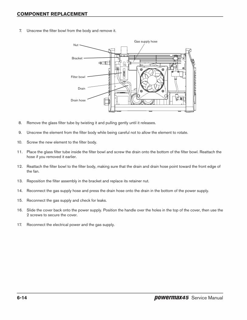
Component replaCement
6-14 powermax45 Service Manual
7. Unscrew the filter bowl from the body and remove it.
8. Remove the glass filter tube by twisting it and pulling gently until it releases.
9. Unscrew the element from the filter body while being careful not to allow the element to rotate.
10. Screw the new element to the filter body.
11. Place the glass filter tube inside the filter bowl and screw the drain onto the bottom of the filter bowl. Reattach the hose if you removed it earlier.
12. Reattach the filter bowl to the filter body, making sure that the drain and drain hose point toward the front edge of the fan.
13. Reposition the filter assembly in the bracket and replace its retainer nut.
14. Reconnect the gas supply hose and press the drain hose onto the drain in the bottom of the power supply.
15. Reconnect the gas supply and check for leaks.
16. Slide the cover back onto the power supply. Position the handle over the holes in the top of the cover, then use the 2 screws to secure the cover.
17. Reconnect the electrical power and the gas supply.
Nut
Bracket
Filter bowl
Drain hose
Gas supply hose
Drain
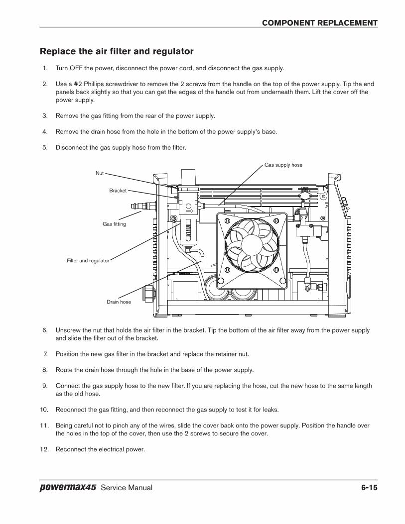
component replacement
powermax45 Service Manual 6-15
Replace the air filter and regulator
1. Turn OFF the power, disconnect the power cord, and disconnect the gas supply.
2. Use a #2 Phillips screwdriver to remove the 2 screws from the handle on the top of the power supply. Tip the end panels back slightly so that you can get the edges of the handle out from underneath them. Lift the cover off the power supply.
3. Remove the gas fitting from the rear of the power supply.
4. Remove the drain hose from the hole in the bottom of the power supply’s base.
5. Disconnect the gas supply hose from the filter.
6. Unscrew the nut that holds the air filter in the bracket. Tip the bottom of the air filter away from the power supply and slide the filter out of the bracket.
7. Position the new gas filter in the bracket and replace the retainer nut.
8. Route the drain hose through the hole in the base of the power supply.
9. Connect the gas supply hose to the new filter. If you are replacing the hose, cut the new hose to the same length as the old hose.
10. Reconnect the gas fitting, and then reconnect the gas supply to test it for leaks.
11. Being careful not to pinch any of the wires, slide the cover back onto the power supply. Position the handle over the holes in the top of the cover, then use the 2 screws to secure the cover.
12. Reconnect the electrical power.
Drain hose
Nut
Bracket
Gas fitting
Filter and regulator
Gas supply hose

Component replaCement
6-16 powermax45 Service Manual
Replace the control board
1. Turn OFF the power, disconnect the power cord, and disconnect the gas supply.
2. Use a #2 Phillips screwdriver to remove the 2 screws from the handle on the top of the power supply. Tip the end panels back slightly so that you can get the edges of the handle out from underneath them. Lift the cover off the power supply. Remove the Mylar barrier that protects the power board.
3. Remove the amperage control knob by pulling it straight out from the end panel.
4. Remove the front end panel, or gently tilt it away from the base.
5. Detach the ribbon cable from the power board at J7 (200–240 V CSA and 230 V CE) or J8 (400 V CE and 480 V CSA).
CAUTIoN
Static electricity can damage circuit boards. Use proper precautions when handling printed circuit boards.
– Store PC boards in anti-static containers.
– Wear a grounded wrist strap when handling PC boards.
6. Test the new control board before installing it by attaching its ribbon cable to the power board. Reconnect the power, turn the system on, and verify that the start LED on the control board is the only LED illuminated. Also, the fault LEDs on the front panel should be extinguished.
7. Disconnect the electrical power and the ribbon cable again, and set aside the new control board.
8. Remove the 3 retaining screws from the old control board and lift it out of the power supply.
9. Screw the new control board into place with the 3 retaining screws and then attach the ribbon cable.
10. Press the amperage control knob onto the post. There is a flat side on the post. Ensure that the flat side of the opening in the knob aligns with the flat side on the post.
11. Reposition the front end panel.
12. Being careful not to pinch any of the wires, replace the Mylar barrier and slide the cover back onto the power supply. Position the handle over the holes in the top of the cover, then use the 2 screws to secure the cover.
13. Reconnect the electrical power and the gas supply.
Control boardRibbon cable

component replacement
powermax45 Service Manual 6-17
Replace the power board (200–240 V CSA and 230 V Ce)Before beginning this procedure, make sure you have the correct power board for your system. The replacement kit number for a 200–240 V CSA power board is 228261. The replacement kit number for a 230 V CE power board is 228259. The procedure below applies to the 200–240 V CSA and the 230 V CE power boards.
1. Turn OFF the power, disconnect the power cord, and disconnect the gas supply.
2. Use a #2 Phillips screwdriver to remove the 2 screws from the handle on the top of the power supply. Tip the end panels back slightly so that you can get the edges of the handle out from underneath them. Lift the cover off the power supply. Remove the Mylar barrier that protects the power board.
CAUTIoN
Static electricity can damage circuit boards. Use proper precautions when handling printed circuit boards.
– Store PC boards in anti-static containers.
– Wear a grounded wrist strap when handling PC boards.
3. Detach the ribbon cable from J7 on the heat sink side of the power board. (See the illustrations following this procedure for the location of the ribbon cable and the components listed in the steps that follow.)
4. Remove the connectors at J10, J12, and J22 on the heat sink side of the power board.
5. Remove the connectors at J3, J4, and J5 on the heat sink side of the power board.
6. Remove the connector for the red and black wires from the power switch at J6 from the heat sink side of the power board. J6 is located about an inch down from the top edge of the board.
7. Remove the wires for the transformers and inductors at J13, J14, J15, J16, J17, J18, J19, and J20.
8. Remove the work lead ring terminal from J21 and the 4 capacitor screws.
9. Remove the 3 retaining screws, the 4 heat sink assembly screws, and the 4 resistor screws.
10. If you have an older 200–240 V CSA or 230 V CE power board that has 2 input bridge diodes (and without the small slot below the heat sink assembly screw hole), remove the 3 screws that attach the IGBTs and the 2 screws that attach the input bridge diodes to the heat sink. There are holes in the power board to provide access to them.
If you have a newer 200–240 V CSA or 230 V CE power board that has a single input bridge diode (and has a small slot below the heat sink assembly screw hole), remove the 3 screws that attach the IGBTs and the screw that attaches the input bridge diode to the heat sink. There are holes in the power board to provide access to them.
11. Remove the screw at J1 that secures the white wire and the screw at J2 that secures the black wire from the ON/OFF switch to the power board.
12. Stand up the unit again. Tuck out of the way all the wires that you detached.
13. Pull the board straight out from the power supply.
Component replaCement
6-18 powermax45 Service Manual
14. Before installing a new power board, clean the heat sink with isopropyl alcohol. Gently scrub away any residual thermal compound, being careful not to scratch the heat sink. Wipe it with a clean cloth.
15. Spread a thin layer of thermal compound (included in the parts kit) 2 mm thick (about the thickness of a sheet of paper) on all the IGBTs and the input bridge diode.
NOTE: Remix the compound if the material separates.
16. Line up the holes for the capacitor screws with the capacitors; the pressure relief vents should be visible from the two notches in the power board.
17. Push the power board straight in.
18. Replace the 4 heat sink assembly screws and torque them to 23.0 kg cm (20 inch-pounds).
19. Replace the 3 retaining screws and the 4 resistor screws. Torque these screws to 17.3 kg cm (15 inch-pounds).
20. Reconnect the white wire from the ON/OFF switch to J1 and the black wire to J2. Torque them to 23.0 kg cm (20 inch-pounds).
21. Replace the 3 screws that attach the IGBTs and the screw that attaches the input bridge diode to the heat sink. The torque setting for these is 23.0 kg cm (20 inch-pounds). (If you replaced an older 200–240 V CSA or 230 V CE power board you will have an additional screw left over.)
22. Replace the 4 capacitor screws. Be sure to reattach the black wire to the left-most screw. Torque these screws to 23.0 kg cm (20 inch-pounds).
23. Reconnect the wires to the transformers and inductors at J13, J14, J15, J16, J17, J18, J19, and J20 and the work lead ring terminal at J21. Torque them to 23.0 kg cm (20 inch-pounds).
24. Replace the connectors at J10 and J12 and the connectors at J3, J4, J5, and J6.
25. Reconnect the ribbon cable from the control board to the power board at J7.
26. Being careful not to pinch any of the wires, replace the Mylar barrier and slide the cover back onto the power supply. Position the handle over the holes in the top of the cover, then use the 2 screws to secure the cover.
27. Reconnect the electrical power and the gas supply.
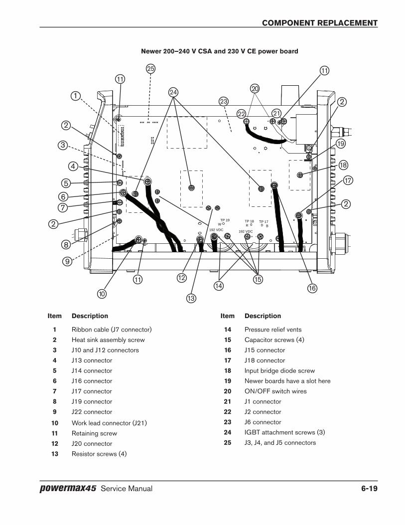
component replacement
powermax45 Service Manual 6-19
Item description
1 Ribbon cable (J7 connector)2 Heat sink assembly screw3 J10 and J12 connectors4 J13 connector5 J14 connector6 J16 connector7 J17 connector8 J19 connector9 J22 connector
10 Work lead connector (J21)11 Retaining screw12 J20 connector13 Resistor screws (4)
Item description
14 Pressure relief vents15 Capacitor screws (4)16 J15 connector17 J18 connector18 Input bridge diode screw19 Newer boards have a slot here20 ON/OFF switch wires21 J1 connector22 J2 connector23 J6 connector24 IGBT attachment screws (3)25 J3, J4, and J5 connectors
Newer 200–240 V CSA and 230 V Ce power board
TP 19W
-+ -+
TP 18R
TP 17B
192 VDC 192 VDC
1
2
2
2
2
3
4
5
67
8
9
10
11 12
13
1415
16
17
18
19
20
2122
2324
1111
25

Component replaCement
6-20 powermax45 Service Manual
Item description
1 Ribbon cable (J7 connector)2 Heat sink assembly screw3 J10 and J12 connectors4 J13 connector5 J14 connector6 J16 connector7 J17 connector8 J19 connector9 J22 connector
10 Work lead connector (J21)11 Retaining screw12 J20 connector
Item description
13 Resistor screws (4)14 Pressure relief vents15 Capacitor screws (4)16 J15 connector17 J18 connector18 Input bridge diode screws (2)19 ON/OFF switch wires20 J1 connector21 J2 connector22 J6 connector23 IGBT attachment screws (3)24 J3, J4, and J5 connectors
TP 19W
-+ -+
TP 18R
TP 17B
192 VDC 192 VDC
older 200–240 V CSA and 230 V Ce power board
1
2
3
4
5
67
8
9
10 11 12
13 1415
16
17
18
19
2021
2223
24
2
2
2
1111
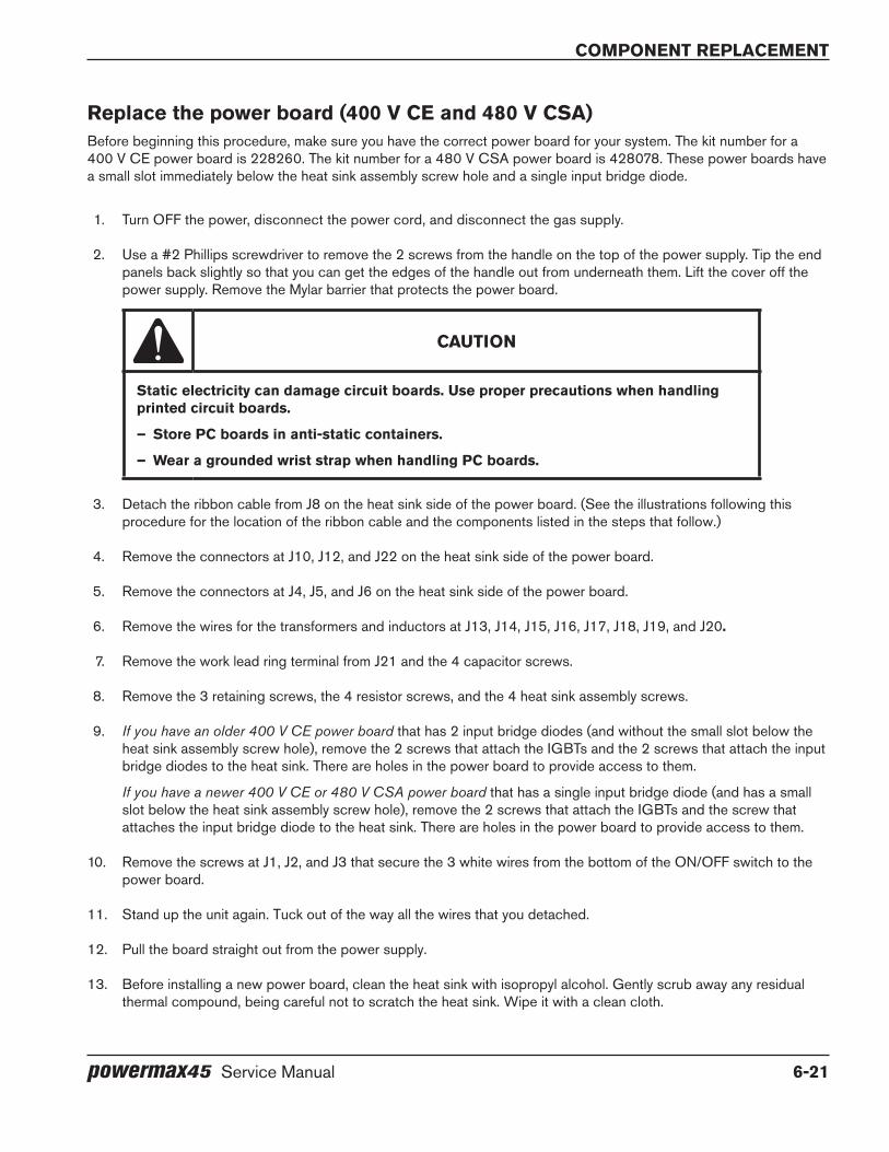
component replacement
powermax45 Service Manual 6-21
Replace the power board (400 V Ce and 480 V CSA)Before beginning this procedure, make sure you have the correct power board for your system. The kit number for a 400 V CE power board is 228260. The kit number for a 480 V CSA power board is 428078. These power boards have a small slot immediately below the heat sink assembly screw hole and a single input bridge diode.
1. Turn OFF the power, disconnect the power cord, and disconnect the gas supply.
2. Use a #2 Phillips screwdriver to remove the 2 screws from the handle on the top of the power supply. Tip the end panels back slightly so that you can get the edges of the handle out from underneath them. Lift the cover off the power supply. Remove the Mylar barrier that protects the power board.
CAUTIoN
Static electricity can damage circuit boards. Use proper precautions when handling printed circuit boards.
– Store PC boards in anti-static containers.
– Wear a grounded wrist strap when handling PC boards.
3. Detach the ribbon cable from J8 on the heat sink side of the power board. (See the illustrations following this procedure for the location of the ribbon cable and the components listed in the steps that follow.)
4. Remove the connectors at J10, J12, and J22 on the heat sink side of the power board.
5. Remove the connectors at J4, J5, and J6 on the heat sink side of the power board.
6. Remove the wires for the transformers and inductors at J13, J14, J15, J16, J17, J18, J19, and J20.
7. Remove the work lead ring terminal from J21 and the 4 capacitor screws.
8. Remove the 3 retaining screws, the 4 resistor screws, and the 4 heat sink assembly screws.
9. If you have an older 400 V CE power board that has 2 input bridge diodes (and without the small slot below the heat sink assembly screw hole), remove the 2 screws that attach the IGBTs and the 2 screws that attach the input bridge diodes to the heat sink. There are holes in the power board to provide access to them.
If you have a newer 400 V CE or 480 V CSA power board that has a single input bridge diode (and has a small slot below the heat sink assembly screw hole), remove the 2 screws that attach the IGBTs and the screw that attaches the input bridge diode to the heat sink. There are holes in the power board to provide access to them.
10. Remove the screws at J1, J2, and J3 that secure the 3 white wires from the bottom of the ON/OFF switch to the power board.
11. Stand up the unit again. Tuck out of the way all the wires that you detached.
12. Pull the board straight out from the power supply.
13. Before installing a new power board, clean the heat sink with isopropyl alcohol. Gently scrub away any residual thermal compound, being careful not to scratch the heat sink. Wipe it with a clean cloth.
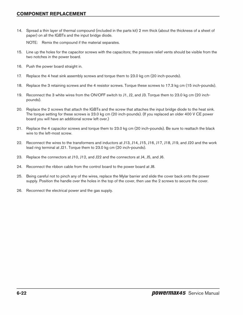
Component replaCement
6-22 powermax45 Service Manual
14. Spread a thin layer of thermal compound (included in the parts kit) 2 mm thick (about the thickness of a sheet of paper) on all the IGBTs and the input bridge diode.
NOTE: Remix the compound if the material separates.
15. Line up the holes for the capacitor screws with the capacitors; the pressure relief vents should be visible from the two notches in the power board.
16. Push the power board straight in.
17. Replace the 4 heat sink assembly screws and torque them to 23.0 kg cm (20 inch-pounds).
18. Replace the 3 retaining screws and the 4 resistor screws. Torque these screws to 17.3 kg cm (15 inch-pounds).
19. Reconnect the 3 white wires from the ON/OFF switch to J1, J2, and J3. Torque them to 23.0 kg cm (20 inch-pounds).
20. Replace the 2 screws that attach the IGBTs and the screw that attaches the input bridge diode to the heat sink. The torque setting for these screws is 23.0 kg cm (20 inch-pounds). (If you replaced an older 400 V CE power board you will have an additional screw left over.)
21. Replace the 4 capacitor screws and torque them to 23.0 kg cm (20 inch-pounds). Be sure to reattach the black wire to the left-most screw.
22. Reconnect the wires to the transformers and inductors at J13, J14, J15, J16, J17, J18, J19, and J20 and the work lead ring terminal at J21. Torque them to 23.0 kg cm (20 inch-pounds).
23. Replace the connectors at J10, J12, and J22 and the connectors at J4, J5, and J6.
24. Reconnect the ribbon cable from the control board to the power board at J8.
25. Being careful not to pinch any of the wires, replace the Mylar barrier and slide the cover back onto the power supply. Position the handle over the holes in the top of the cover, then use the 2 screws to secure the cover.
26. Reconnect the electrical power and the gas supply.
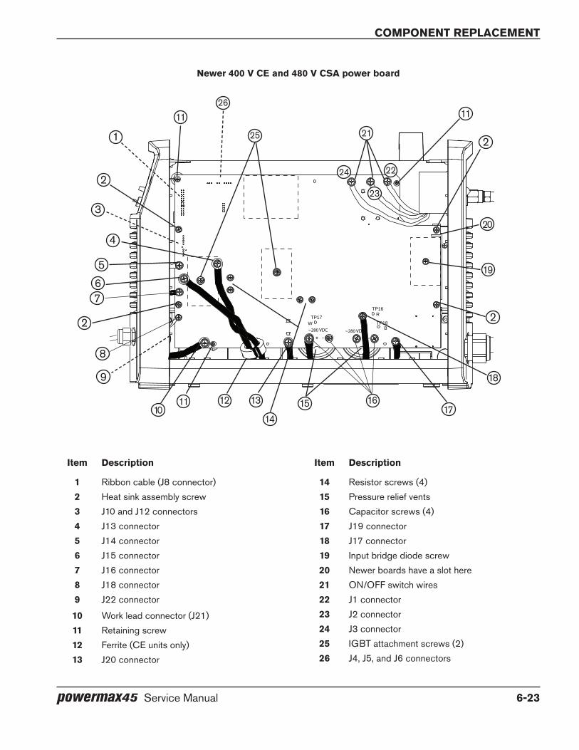
component replacement
powermax45 Service Manual 6-23
Item description
1 Ribbon cable (J8 connector)2 Heat sink assembly screw3 J10 and J12 connectors4 J13 connector5 J14 connector6 J15 connector7 J16 connector8 J18 connector9 J22 connector
10 Work lead connector (J21)11 Retaining screw12 Ferrite (CE units only)13 J20 connector
Item description
14 Resistor screws (4)15 Pressure relief vents16 Capacitor screws (4)17 J19 connector18 J17 connector19 Input bridge diode screw20 Newer boards have a slot here21 ON/OFF switch wires22 J1 connector23 J2 connector24 J3 connector25 IGBT attachment screws (2)26 J4, J5, and J6 connectors
TP17W
+ - + -
TP18B
TP16R
~280 VDC~280 VDC
Newer 400 V Ce and 480 V CSA power board
1
2
3
4
567
8
9
1011 12 13
1415 16
17
18
19
20
21
22
23
24
25
26
2 2
2
1111
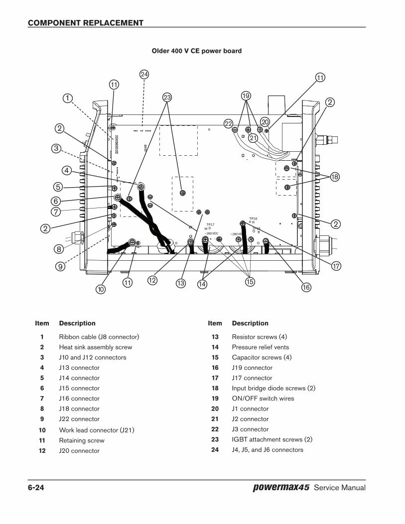
Component replaCement
6-24 powermax45 Service Manual
Item description
1 Ribbon cable (J8 connector)2 Heat sink assembly screw3 J10 and J12 connectors4 J13 connector5 J14 connector6 J15 connector7 J16 connector8 J18 connector9 J22 connector
10 Work lead connector (J21)11 Retaining screw12 J20 connector
Item description
13 Resistor screws (4)14 Pressure relief vents15 Capacitor screws (4)16 J19 connector17 J17 connector18 Input bridge diode screws (2)19 ON/OFF switch wires20 J1 connector21 J2 connector22 J3 connector23 IGBT attachment screws (2)24 J4, J5, and J6 connectors
older 400 V Ce power board
TP17W
+ - + -
TP18B
TP16R
~280 VDC~280 VDC
1
2
3
4
5
67
8
9
1011 12 13 14 15
16
17
18
19
20
21
22
23
24
2 2
2
1111

powermax45 Service Manual 7-1
Section 7
PARTS
In this section:
Power supply parts ....................................................................................................................................................................................7-2Exterior ...............................................................................................................................................................................................7-2Interior, power board side ..............................................................................................................................................................7-4Interior, fan side ................................................................................................................................................................................7-5Interior, heat sink side .....................................................................................................................................................................7-6
T45v hand torch parts ...............................................................................................................................................................................7-7T45v hand torch consumables .....................................................................................................................................................7-8T30v (Powermax30) 30 A consumables ...................................................................................................................................7-8
T45m machine torch parts .......................................................................................................................................................................7-9T45m machine torch consumables ...........................................................................................................................................7-10
Accessory parts........................................................................................................................................................................................7-10Safety-critical parts ................................................................................................................................................................................ 7-11Recommended spare parts .................................................................................................................................................................. 7-12Powermax45 labels ................................................................................................................................................................................ 7-13

PARTS
7-2 powermax45 Service Manual
Power supply parts
exterior
1
2
3 4
5 6 7
89
10
11
Item Part number description Qty.
228270 Kit: Cover screws 11 228269 Kit: Front panel 12 108616 Current adjustment knob 13 228300 Kit: Work lead assembly, 6.1 m (20 feet) 14 228307 Kit: Work lead assembly, 15.24 m (50 feet) 15 228281 Kit: Power supply cover with labels, 200–240 V CSA 16 228283 Kit: Power supply cover with labels, CE 17 428076 Kit: Power supply cover with labels (Built in America), 480 V CSA 18 228268 Kit: Rear panel 19 228267 Kit: Powermax45 handle and screws 110 228282 Kit: FastConnectTM replacement (power supply half) 111 228561 Kit: Ground clamp 1
Parts
powermax45 Service Manual 7-3
Power cord
Receptacle for machine interface cable or remote start pendant
Part number description
228278 Kit: CSA power cord, 1-phase, 200–240 V, 3 m (10 feet)228277 Kit: CE power cord, 1-phase, 230 V, 3 m (10 feet)228276 Kit: CE power cord, 3-phase, 400 V, 3 m (10 feet)428077 Kit: CSA power cord, 3-phase, 480 V, 3 m (10 feet)023206 Machine interface cable (start plasma, arc transfer, and ground), 7.62 m (25 feet)023279 Machine interface cable (start plasma, arc transfer, and ground), 15.24 m (50 feet)123966 Powermax45 machine interface cable (start plasma, arc transfer, 50:1 voltage divider, and ground),
7.62 m (25 feet), spade connectors123967 Powermax45 machine interface cable (start plasma, arc transfer, 50:1 voltage divider, and ground),
15.24 m (50 feet), spade connectors223048 Machine interface cable (start plasma, arc transfer, 50:1 voltage divider, and ground), 7.62 m
(25 feet), D-sub connector with screws123896 Machine interface cable (start plasma, arc transfer, 50:1 voltage divider, and ground), 15.24 m
(50 feet), D-sub connector with screws
PARTS
7-4 powermax45 Service Manual
TP 19W
-+ -+
TP 18R
TP 17B
192 VDC 192 VDC
Interior, power board side
1 2 34 5 6
8 9 10
7
11 12
ItemPart number description designator Qty.
1 228262 Kit: Control board, 200–240 V CSA, 230 V CE, 400 V CE PCB1 1428098 Kit: Control board, 480 V CSA PCB1 1
2 228266 Kit: Powermax45 power switch, 200–240 V CSA and 230 V CE 13 228288 Kit: Powermax45 power switch, 400 V CE and 480 V CSA 14 228261 Kit: Power board, 200–240 V CSA PCB2 15 428078 Kit: Power board, 480 V CSA PCB2 16 228260 Kit: Power board, 400 V CE PCB2 17 228259 Kit: Power board, 230 V CE PCB2 18 228258 Kit: Base 19 228265 Kit: Magnetics assembly, 200–240 V CSA 110 228273 Kit: Magnetics assembly, 230 V CE 111 228263 Kit: Magnetics assembly, 400 V CE 112 428079 Kit: Magnetics assembly, 480 V CSA 1
228279 Kit: Powermax45 insulator (not shown) 1228290 Kit: Powermax45 wire group (not shown) 1

Parts
powermax45 Service Manual 7-5
Interior, fan side
12
6
78
3
45
ItemPart number description designator Qty.
1 228284 Kit: Pressure sensor cable 12 228285 Kit: Solenoid valve V1 13 015337 Quick disconnect, 1/4”, NPT, stainless nipple 14 015551 1/4” brass coupling 15 015511 1/4” X 2” brass nipple 16 228287 Kit: Filter and regulator 17 228302 Kit: Air filter element 18 228286 Kit: Fan assembly M1 1

PARTS
7-6 powermax45 Service Manual
Interior, heat sink side
1 2
Item Part number description Qty.
1 428065 Kit: Snubber resistors 22 228301 Kit: Capacitors, 200–240 V CSA and 230 V CE 2
228426 Kit: Capacitors, 400 V CE 2428080 Kit: Capacitors, 480 V CSA 2

Parts
powermax45 Service Manual 7-7
T45v hand torch parts
1
2
3
4
5
6
87
9
The entire hand torch and lead assembly can be replaced, or individual component parts can be replaced. Part numbers starting with 088 indicate complete torch and lead assemblies.
Item Part number description Qty.
088008* T45v hand torch assembly with 6.1 m (20 feet) lead 1088009* T45v hand torch assembly with 15.24 m (50 feet) lead 1
1 228313 Kit: T45v torch handle replacement 12 075714 T45v torch handle screws, #4 x 1/2 SLTD Torx PAN, S/B 53 002244 Safety trigger and spring replacement 14 228346 Kit: Torch head replacement 15 058503 O-ring: Viton 0.626 x 0.070 16 228109 Kit: T45v torch cap-sensor switch replacement 17 228315 Kit: T45v torch lead replacement, 6.1 m (20 feet) 18 228316 Kit: T45v torch lead replacement, 15.24 m (50 feet) 19 128642 Kit: Start switch replacement 1
* The torch assembly also includes one set of the consumables listed on the next page.
PARTS
7-8 powermax45 Service Manual
T45v hand torch consumables
Part number description
Shielded220669 Electrode220670 Swirl ring220713 Retaining cap220671 Nozzle220674 Shield
gouging*220675 Shield220672 Nozzle
Unshielded*220717 Deflector220718 Nozzle
* The swirl ring, retaining cap, and electrode for these applications are the same as those for the shielded application. Unshielded consumables for the hand torch are not available in CE-regulated countries.
T30v (Powermax30) 30 A consumables
Part number description
220569 Deflector220483 Retaining cap220480 Nozzle220479 Swirl ring220478 Electrode

Parts
powermax45 Service Manual 7-9
1
4
5
T45m machine torch parts
6
7
8 9 10
3
2
The entire machine torch and lead assembly can be replaced, or individual component parts can be replaced. Part numbers starting with 088 indicate complete torch and lead assemblies.
Item Part number description Qty.
088010* T45m machine torch assembly with 7.62 m (25 feet) lead 1088011* T45m machine torch assembly with 10.67 m (35 feet) lead 1088012* T45m machine torch assembly with 15.24 m (50 feet) lead 1
1 228228 Kit: T45m positioning sleeve 12 228229 Kit: T45m removable gear rack 13 228322 Kit: T45m front mounting ring 14 228323 Kit: T45m rear mounting ring 15 228320 Kit: T45m torch head replacement 16 228321 Kit: T45m cap-sensor switch replacement 17 058503 O-ring: Viton 0.626 x 0.070 18 228317 Kit: T45m torch lead replacement, 7.62 m (25 feet) 19 228318 Kit: T45m torch lead replacement, 10.67 m (35 feet) 110 228319 Kit: T45m torch lead replacement, 15.24 m (50 feet) 1
* Top assembly includes one set of the following consumables:220669 Electrode 1220670 Swirl ring 1220713 Retaining cap 1220671 Nozzle 1220673 Shield 1
PARTS
7-10 powermax45 Service Manual
T45m machine torch consumables
Part number description
Shielded220669 Electrode220670 Swirl ring220713 Retaining cap220719 Ohmic sensing retaining cap220671 Nozzle220673 Shield
Unshielded*220717 Deflector220718 Nozzle
* The swirl ring, retaining cap, and electrode for the unshielded application are the same as those for the shielded application.
The T30v (Powermax30) 30 A consumables can be used on the T45m as well. The part numbers are listed under T30v (Powermax30) 30 A consumables on page 7-8.
Accessory partsPart number description
024548 Brown leather torch sheathing, 7.5 m (25 feet)024877 Black leather torch sheathing, 7.5 m (25 feet)128658 Gouging heat shield127102 Basic plasma (circle) cutting guide027668 Deluxe plasma (circle) cutting guide127219 Powermax45 dust cover127217 Powermax45 shoulder strap128647 Kit: Eliminizer air filtration127103 Face shield, shade 8 lens127239 Face shield, shade 6 lens127105 Replacement lens for face shield, shade 8127243 Replacement lens for face shield, shade 6127169 Leather cutting gloves128650 Remote start pendant for machine torch, 7.62 m (25 feet)128651 Remote start pendant for machine torch, 15.24 m (50 feet)128652 Remote start pendant for machine torch, 22.86 m (75 feet)

Parts
powermax45 Service Manual 7-11
Safety-critical partsGenuine Hypertherm parts are the factory-recommended parts for your Hypertherm system. Any damage caused by the use of other than genuine Hypertherm parts may not be covered by the Hypertherm warranty. In addition, the parts listed below are considered safety-critical parts that must be replaced only with Hypertherm parts to maintain the warranty and all system certifications, including CE, CSA, GOST, and CCC certification.
1
2
3
4
TP 19W
-+ -+
TP 18R
TP 17B
192 VDC 192 VDC
Item Part number description
1 228261 Kit: Power board (200–240 V CSA) and subcomponents228260 Kit: Power board (400 V CE) and subcomponents228259 Kit: Power board (230 V CE) and subcomponents428078 Kit: Power board (480 V CSA) and subcomponents
2 228265 Kit: Magnetics assembly, 200–240 V CSA228273 Kit: Magnetics assembly, 230 V CE228263 Kit: Magnetics assembly, 400 V CE428079 Kit: Magnetics assembly, 480 V CSA
3 228287 Kit: Filter and regulator4 228286 Kit: Fan assembly5 228266 Kit: Powermax45 power switch, 200–240 V CSA and 230 V CE
228288 Kit: Powermax45 power switch, 400 V CE and 480 V CSA228278 Kit: CSA power cord, 1-phase, 200–240 V, 3 m (10 feet) (not shown)228277 Kit: CE power cord, 1-phase, 230 V, 3 m (10 feet) (not shown)228276 Kit: CE power cord, 3-phase, 400 V, 3 m (10 feet) (not shown)428077 Kit: CSA power cord, 3-phase, 480 V, 3 m (10 feet) (not shown)
5

PARTS
7-12 powermax45 Service Manual
Recommended spare partsHypertherm recommends that service centers keep the following spare parts on hand for repairs, either because these parts are critical or because they are usually exposed to heavy and repeated wear. You may find that you need to revise or expand this list for your customers, based on the particular conditions for your region and working environments.
Part number descriptionPage
reference
228561 Kit: Ground clamp 7-2228300 Kit: Work lead assembly, 6.1 m (20 feet) 7-2228266 Kit: Powermax45 power switch, 200–240 V CSA and 230 V CE 7-4228288 Kit: Powermax45 power switch, 400 V CE and 480 V CSA 7-4228262 Kit: Control board, 200–240 V CSA, 230 V CE, 400 V CE 7-4428098 Kit: Control board, 480 V CSA 7-4228261 Kit: Power board, 200–240 V CSA 7-4428078 Kit: Power board, 480 V CSA 7-4228260 Kit: Power board, 400 V CE 7-4228259 Kit: Power board, 230 V CE 7-4228285 Kit: Solenoid valve 7-5228287 Kit: Filter and regulator 7-5228302 Kit: Air filter element 7-5058503 O-ring: Viton 0.626 x 0.070 7-7228313 Kit: T45v torch handle replacement 7-7075714 T45v torch handle screws (5 required) 7-7002244 T45v torch trigger assembly with spring 7-7228109 Kit: T45v torch cap-sensor switch replacement 7-7088008 T45v hand torch assembly with 6.1 m (20 feet) lead 7-7088009 T45v hand torch assembly with 15.24 m (50 feet) lead 7-7228315 Kit: T45v torch lead replacement, 6.1 m (20 feet) 7-7228316 Kit: T45v torch lead replacement, 15.24 m (50 feet) 7-7088010 T45m machine torch assembly with 7.62 m (25 feet) lead 7-9088012 T45m machine torch assembly with 15.24 m (50 feet) lead 7-9228228 Kit: T45m positioning sleeve 7-9228229 Kit: T45m removable gear rack 7-9228322 Kit: T45m front mounting ring 7-9228323 Kit: T45m rear mounting ring 7-9228321 Kit T45m cap-sensor switch replacement 7-9228317 Kit: T45m torch lead replacement, 7.62 m (25 feet) 7-9228319 Kit: T45m torch lead replacement, 15.24 m (50 feet) 7-9

Parts
powermax45 Service Manual 7-13
Powermax45 labels
Part number description
228272 Kit: Powermax45 labels, CE228264 Kit: Powermax45 labels, 200–240 V CSA428075 Kit: Powermax45 labels (Built in America), 480 V CSA
The label kits include the consumable label, appropriate safety labels, as well as front and side decals. The consumable and safety labels are pictured below.
Data platePlaque signalètiqueT45v CONSUMABLE PARTS
Pièces Consommables T45v
110672 Rev. B
220674
220675
220717
220713
220672
220671
220718
220670 220669
Consumable label
www.hypertherm.com/weee110647 Rev. B
CE safety label
Read and follow these instructions, employer safetypractices, and material safety data sheets. Refer to ANS Z49.1, “Safety in Welding, Cutting and Allied Processes” from American Welding Society (http://www.aws.org) and OSHA Safety and Health Standards, 29 CFR 1910 (http://www.osha.gov).
WARNINg
1. Cutting sparks can cause explosion or fire.1.1 Do not cut near flammables.1.2 Have a fire extinguisher nearby and ready to use.1.3 Do not use a drum or other closed container as a cutting table.
2. Plasma arc can injure and burn; point the nozzle away from yourself. Arc starts instantly when triggered. 2.1 Turn off power before disassembling torch.2.2 Do not grip the workpiece near the cutting path.2.3 Wear complete body protection.
3. Hazardous voltage. Risk of electric shock or burn.3.1 Wear insulating gloves. Replace gloves when wet or damaged.3.2 Protect from shock by insulating yourself from work and ground.3.3 Disconnect power before servicing. Do not touch live parts.
4. Plasma fumes can be hazardous.4.1 Do not inhale fumes. 4.2 Use forced ventilation or local exhaust to remove the fumes.4.3 Do not operate in closed spaces. Remove fumes with ventilation.
6. become trained. Only qualified personnel should operate this equipment. Use torches specified in the manual. Keep non-qualified personnel and children away.
5. Arc rays can burn eyes and injure skin.5.1 Wear correct and appropriate protective equipment to protect head, eyes, ears, hands, and body. Button shirt collar. Protect ears from noise. Use welding helmet with the correct shade of filter.
7. do not remove, destroy, or cover this label. Replace if it is missing, damaged, or worn.
Plasma cutting can be injurious to operator and persons in the work area. Consult manual before operating. Failure to follow all these safety instructions can result in death.
(PN 110673 Rev D)
AVeRTISSeMeNTLe coupage plasma peut être préjudiciable pour l’opérateur et les personnes qui se trouvent sur les lieux de travail. Consulter le manuel avant de faire fonctionner. Le non respect des ces instructions de sécurité peut entraîner la mort.
1. les étincelles de coupage peuvent provoquer une explosion ou un incendie.1.1 Ne pas couper près des matières inflammables. 1.2 Un extincteur doit être à proximité et prêt à être utilisé.1.3 Ne pas utiliser un fût ou un autre contenant fermé comme table de coupage.
2. l’arc plasma peut blesser et brûler; éloigner la buse de soi. Il s’allume instantanément quand on l’amorce. 2.1 Couper l’alimentation avant de démonter la torche. 2.2 Ne pas saisir la pièce à couper de la trajectoire de coupage. 2.3 Se protéger entièrement le corps.
3. Tension dangereuse. Risque de choc électrique ou de brûlure. 3.1 Porter des gants isolants. Remplacer les gants quand ils sont humides ou endommagés. 3.2 Se protéger contre les chocs en s’isolant de la pièce et de la terre. 3.3 Couper l’alimentation avant l’entretien. Ne pas toucher les pièces sous tension.4. les fumées plasma peuvent être dangereuses. 4.1 Ne pas inhaler les fumées. 4.2 Utiliser une ventilation forcée ou un extracteur local pour dissiper les fumées. 4.3 Ne pas couper dans des espaces clos. Chasser les fumées par ventilation.
5. les rayons d’arc peuvent brûler les yeux et blesser la peau. 5.1 Porter un bon équipement de protection pour se protéger la tête, les yeux, les oreilles, les mains et le corps. Boutonner le col de la chemise. Protéger les oreilles contre le bruit. Utiliser un masque de soudeur avec un filtre de nuance appropriée.
6. Suivre une formation. Seul le personnel qualifié a le droit de faire fonctionner cet équipement. Utiliser exclusivement les torches indiquées dans le manual. Le personnel non qualifié et les enfants doivent se tenir à l’écart.
7. Ne pas enlever, détruire ni couvrir cette étiquette. La remplacer si elle est absente, endommagée ou usée.
(PN 110673 Rev D)
CSA safety label
Maximum pressure label

PARTS
7-14 powermax45 Service Manual

powermax45 Service Manual 8-1
Section 8
WIRINg dIAgRAMS
In this section:
Control board diagram: 200–240 V CSA and 230 V CE ...............................................................................................................8-2Control board diagram: 400 V CE and 480 V CSA ..........................................................................................................................8-3Power board wiring diagram: 200–240 V CSA and 230 V CE .....................................................................................................8-5Power board wiring diagram: 400 V CE ..............................................................................................................................................8-6Power board wiring diagram: 480 V CSA ...........................................................................................................................................8-7

Wiring Diagrams
8-2 powermax45 Service Manual
FAULT
YEL
AMPS
CW
CAPOFF
YEL
"TSO/TSC"AC PWR
GRN
"L/H LINE"
720
IN15
IN9
V-8 IN7
IN13
IN12
IN11
IN10IN
6
V+16
IN3 IN2 IN1
IN5
IN14
IN4
JTAG13579
1113 14
24681012
1 2
3 4
5 6
7 8
9 10
11 12
13 14
15 16
17 18
19 20
21 22
23 24
25 26
2
1
3
4 567
ON
ON CASE
CASE
1
2
3
4
TEMP
YEL
L R
1
ERRORCODE
.25"FORBDDEPAN-IZATION
SERIALDATA
MACHINEFRONT
DSP 28064x25Mhz=100Mhz0.78 x 0.78"Stayout forTEST CLIP
/RESET orHDR FLT STARTXFR
GAS
CONTROL PWA
CPA (UP)
NORMAL (MIDDLE)
GOUGE (DOWN)
YEL
YEL
GRN
"SETPOINT"
GRN
GRN
MODE
45 A 230 V
Control board diagram: 200–240 V CSA and 230 V Ce
J7 pin number to ground Testexpected value
(200–240 V CSA or 230 V Ce)
19 VACR (rectified AC line voltage) 1.95 V at 230 line voltage
21 VBUS (DC bus voltage) 2.28 VDC at 385 VBUS
18(200–240 and 230 V only)
IPFC (input current) < 0.1 VDC
20 IFB (output current) < 0.1 VDC
22 ITF (transfer current) < 0.1 VDC
25 3.3 VDC 3.3 VDC ±5%
24 5 VDC 5 VDC ±5%
12 24 V sense pin 2.2 VDC
16 Start signal3.2 VDC closed0 VDC open

Wiring Diagrams
powermax45 Service Manual 8-3
1 2
3 4
5 6
7 8
9 10
11 12
13 14
15 16
17 18
19 20
21 22
23 24
25 26
CAPOFF1
YEL
"TSO/TSC"FAULT1
YEL
1
2
3
4
JTAG113579
1113 14
24681012
AC PWR1
GRN
"L/H LINE"
720IN 15
IN 9V-8 IN7
IN 13IN 12IN 11IN 10IN6
V+ 16
IN3 IN2 IN1
IN5IN 14
IN4AMPS1
CW
TEMP1
YEL
2
1
3
4 567
ON
ON CASE
CASE
GRN
L R
1
ERRORCODE
.25"FORBDDEPAN-IZATION
SERIALDATA
MACHINEFRONT
DSP 28064x25Mhz=100Mhz0.78 x 0.78"Stayout forTEST CLIP
/RESET orHDR FLT STARTXFR
GAS
CONTROL PWA45 A 400 V SYS
MODE
CPA (UP)
NORMAL (MIDDLE)
GOUGE (DOWN)
YEL
YEL
GRN
"SETPOINT"
GRN
Control board diagram: 400 V Ce and 480 V CSA
J8 pin number to ground Testexpected value
(400 V Ce or 480 V CSA)
19 VACR (rectified AC line voltage)2.7 V at 400 line voltage (CE)2.016 VDC at 480 line voltage (CSA)
21 VBUS (DC bus voltage)2.178 VDC at 560 VBUS (CE)2.016 VDC at 670 VBUS (CSA)
20 IFB (output current) < 0.1 VDC
22 ITF (transfer current) < 0.1 VDC
25 3.3 VDC 3.3 VDC ±5%
24 5 VDC 5 VDC ±5%
12 24 V sense pin 2.2 VDC
16 Start signal3.2 VDC closed0 VDC open

Wiring Diagrams
8-4 powermax45 Service Manual

8-5
5
5
4
4
3
3
2
2
1
1
D D
C C
B B
A A
J10
0.01uF300vac
J13
-+
J22
L9338MD
8.2uF630VDC
J2
5600uF250VDC
+
LAX100-NP
J5
HCPL-7840
+-+-
VDD1VIN+VIN-GND1 GND2
VOUT-VOUT+
VDD2
t
K6
240VAC00319230A
-+
J15
8.2nF1000VDC
154W
1.2uF630VDC
JUMPER=50'
J7
8.2uF630VDC
J16
1200V60A
t
4.7nF300vacY2
L1
1.2uF630VDC
20K3W
154W
10 ohm120W ISOTOP
100K3W
600V100A
ISP752
J4
JUMPER=MECH
D391600V
50A
J6
J14600V100A
J17
J18
t
-+
J20
275VAC
J1
3844
154W
27K 3W
CLAMP DIODE60A 600V
50A/250V with 32v TRIP COIL
10 ohm120W ISOTOP
2.00K
60A 600VPFC DIODE
8.2nF1000VDC
8.2uF630VDC
75k 2w
27K 3W
Y Cap300vac +-
+-
VDD1VIN+VIN-GND1 GND2
VOUT-VOUT+VDD2
J19
5600uF250VDC
+
4.7nF300vacY2
J21
600V130A
27K 3W
J12
K5003192240VAC30A
LAX100-NP
D291600V
50A
27K 3W
J3
LAX100-NP
18 INVU
COM INVU
+9
18T
+24
18PA
COMPA
COMT
18REG
+3.3+3.3
+5
INV IPRIM
SSR
/PFC DESAT
/INV DESAT
PFC PWM
INVU PWM
INVL PWM
PA
/PA DESAT
CAP ON
GAS OK
START
GAS
SSR
FAN
INVU PWM DRV
INVL PWM DRV
PFC PWM DRV
PA DRV
REDUNDANT START
GAS
FAN
MM
GAS PRES
12345
123
IN2
2D
IAG
3G
ND
4G
ND
5G
ND
6G
ND
7VS
8IN
39
EN
11
OU
T119
IN1
1
OU
T218
GN
D17
GN
D16
GN
D15
GN
D14
OU
T313
OU
T412
PR
G20
IN4
10
M
+-
IN1
IN2
IN3
OU
T3
OU
T1
OU
T2
123
1234
8765
IN1515
IN99IN88IN77
IN1313IN1212IN1111IN1010
IN66
IN1616
IN33IN22IN11
IN55
IN1414
IN44
IN1717
IN1818
IN1919
TDO 40
SPI EN 32
TCK 42TDI 43VCC 44
TMS 41
OUT1 20OUT2 21OUT3 22OUT4 23OUT5 24OUT6 25OUT7 26OUT8 27
I/O 28
SPI IN 31
SPI CLK 30
SPI OUT29
4
12
3
IN OUT
GN
D
1 23 45 67 89 1011 1213 1415 1617 1819 2021 2223 2425 26
1412
43
CPC-5CPC-6
13
IN OUT
GN
D
GND1
IN2
OUT3
ST4
Vbb 8
Vbb 7
Vbb 6
Vbb 5
12
ACAC
-+
12
2
1
3
CMP1
FB2
ISNS3
RT/CT4
VREF 8
VCC 7
OUT 6
GND 5
123
1234
8765
1
23
45
67
8 9
1011
1213
1415
16
1234
4
12
3
M+-
IN1
IN2
IN3OUT3
OUT1
OUT2
ACAC
-+
1234
M+-
IN1
IN2
IN3OUT3
OUT1
OUT2
8AWG BLK
ORG
VIOLET
BLUE
385VDC
18AWG RED
/OVLO
/INV SAT
/DRV FLT
/SS
R
/PFC OC
/UVLO
IGBT TEMP
/PWRFLT
+24
/MM
/5 or 24 FLT
/CAP UNBAL
CPC-5
CPC-6
18AWG WHT
18AWG RED
+5
-Vbus
+24
/SSR
Vacr
Vbus
26 POSRIBBONCABLE
ELECTRODE
NOZZLE
WORK
POWER PWA 230V CSA = 141005 (Top Level) 230V CE = 141046 (Top Level) 8.45"h x 13.00"w 2oz plated to 3oz FACING COMPONENT SIDE OF PCB
FAN 190CFM 24v/1.0A
Finv=36khz
CAP NC
START
LIFT to Hipot
LOW INDUCTANCE VBUS LAYOUT
MTG4
MTG6
MTG3
CONTROL to CHASSIS GND
200-240vac 47-63hz
PE
10AWG
LIFT to Hipot
MTG5
Fpfc=24khz
Iline Limit
58arms
MACHINE REAR
Loutput 014316 L0=480uH L45=205uH Rdc25C=12.5mohm
POWER XFMR CSA = 014315 CE = 014331 Lprim=0.53mH Rprim25C=2.5mohm Rsec25C=5.7mohm
Lleak=0.5uH typ
10T
Lpfc 014314 L0=300uh L75=180uh Rdc25C=10.8mohm
GAS SOL 24v/0.13A
7T
y=1.965"-5.942" 0.472" MAX Ht
y = 5.942"-8.450" 1.92" MAX Ht
y=0.00"-1.965" 1.22" MAX Ht
1
1,2
11,12,13
15,16
15
15
2828
28
3336
MUELLER CLIP
+ARC V
-ARC V
E36/18/11
CPLD 100 Pin
WHT
HEAT SINK
nc
CM Choke CE unit only
385vdc
INPUT BRIDGES
PFC IGBT
MODULE
INVERTER IGBT MODULE
OUTPUT DIODE and PILOT ARC IGBT MODULE
OUTPUT CURRENT SENSOR
TRANSFER
SENSOR
45A/132v OCV = 275v CPA 225v
2932
22
19
2.2uF 300vac X2
2.40" x 1.65" 1.60" max zone
14 Pin CPC REAR of UNIT
6,720,21
25,26,27
To J13, J16
GND START XFR
ELEC (50:1)
WORK
PRESSURE SENSOR
10 ohm NTC
POWER CORD
-Vbus
20
21
234
16
1
2
21
22
7
8
13
14
27ARC VOLTAGE
50:15 (-)6 (+)
C
C
C
C
(-)(+)
C
ELEC SCH:45A 230V SYSTEM
C
013366SHEET 1OF 1
36 35 34 33
Power board wiring diagram: 200–240 V CSA
and 230 V Ce
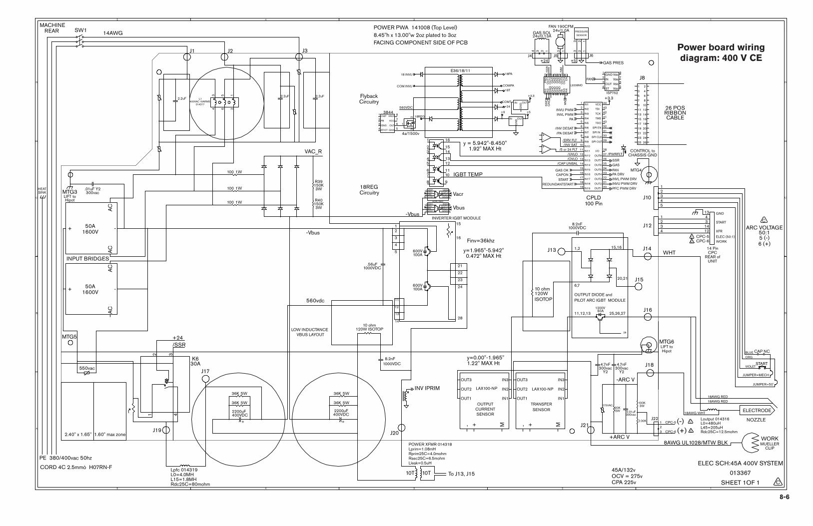
8-65
5
4
4
3
3
2
2
1
1
D D
C C
B B
A A
J10
0.01uF300vac
J13
L1400VAC 10ARMS
014317
-+
J22
2.2uF
J1
L9338MD
J17
2200uF400VDC
+
J6
R39150K3W
HCPL-7840
+-+-
VDD1VIN+VIN-GND1 GND2
VOUT-VOUT+
VDD2
K630A
8.2nF1000VDC
R40150K3W
.56uF1000VDC
J19
JUMPER=50'
J8
J15
2.2uF
1200V60A
4.7nF300vac
Y2
100 1W
20K3W
100 1W
10 ohm120W ISOTOP
100K3W
600V100A
ISP752
J5
JUMPER=MECH
1600V50A
100 1W
J14600V100A
J16
t
-+
J20
275VAC
36K 5W
3844
SW1
10 ohm120W ISOTOP
36K 5W
2.00K
8.2nF1000VDC
.01uF Y2300vac +-+
-
VDD1VIN+VIN-GND1 GND2
VOUT-VOUT+
VDD2
J18
2200uF400VDC
+
J2
36K 5W
4.7nF300vac
Y2
J21
2.2uF
J12
36K 5W
LAX100-NP
1600V50A
J4
LAX100-NP
J3
t
18 INVU
COM INVU
+9
18T
+24
18PA
COMPA
COMT
18REG
+3.3 +3.3
+5
INV IPRIM
SS
R
/INV DESAT
INVU PWMINVL PWM
PA
/PA DESAT
CAPONGAS OK
START
GASSSR
FAN
INVU PWM DRVINVL PWM DRV
PFC PWM DRV
PA DRV
REDUNDANTSTART
GAS
FAN
MM
GAS PRES
12345
134
56 2
123
IN2
2D
IAG
3G
ND
4G
ND
5G
ND
6G
ND
7VS
8IN
39
EN
11
OU
T119
IN1
1
OU
T218
GN
D17
GN
D16
GN
D15
GN
D14
OU
T313
OU
T412
PR
G20
IN4
10
123
1234
8765
IN1515
IN99IN88IN77
IN1313IN1212IN1111IN1010
IN66
IN1616
IN33IN22IN11
IN55
IN1414
IN44
IN1717
IN1818
IN1919
TDO 40
SPI EN 32
TCK 42TDI 43VCC 44
TMS 41
OUT1 20OUT2 21OUT3 22OUT4 23OUT5 24OUT6 25OUT7 26OUT8 27I/O 28
SPI IN 31
SPI CLK 30
SPI OUT 29
412 3
IN OUT
GN
D
1 23 45 67 89 1011 1213 1415 1617 1819 2021 2223 2425 26
1412
43
CPC-5CPC-6
13
IN OUT
GN
D
GND1
IN2
OUT3
ST4
Vbb 8
Vbb 7
Vbb 6
Vbb 5
12
ACAC
-+
2
1
3
CMP1
FB2
ISNS3
RT/CT4
VREF 8
VCC 7
OUT 6
GND 5
123
1234
8765
1
23
45
67
8 9
1011
1213
1415
16
1234
M+-
IN1
IN2
IN3OUT3
OUT1
OUT2
ACAC
-+
1234
M+-
IN1
IN2
IN3OUT3
OUT1
OUT2
8AWG UL1028/MTW BLK
ORG
VIOLET
BLUE
560VDC
18AWG RED
/OVLO
/INV SAT/DRV FLT
/SS
R
/UVLO
IGBT TEMP
/PWRFLT
+24
/MM
/5 or 24 FLT
/CAP UNBAL
CPC-5
CPC-6
18AWG WHT
18AWG RED
+5
-Vbus
+24/SSR
VAC_R
Vacr
Vbus
26 POSRIBBONCABLE
ELECTRODE
NOZZLE
WORK
POWER PWA 141008 (Top Level) 8.45"h x 13.00"w 2oz plated to 3oz FACING COMPONENT SIDE OF PCB
FAN 190CFM 24v/1.0A
Finv=36khz
CAP NC
START
LIFT to Hipot
LOW INDUCTANCE VBUS LAYOUT
MTG4
MTG6
MTG3
CONTROL to CHASSIS GND
380/400vac 50hzPE
14AWG
LIFT to Hipot
MTG5
MACHINE REAR
Loutput 014316 L0=480uH L45=205uH Rdc25C=12.5mohm
POWER XFMR 014318 Lprim=1.08mH Rprim25C=4.0mohm Rsec25C=6.5mohm Lleak=0.5uH
10TLpfc 014319 L0=4.0MH L15=1.8MH Rdc25C=80mohm
GAS SOL 24v/0.13A
10TCORD 4C 2.5mmò H07RN-F
y=1.965"-5.942" 0.472" MAX Ht
y = 5.942"-8.450" 1.92" MAX Ht
y=0.00"-1.965" 1.22" MAX Ht
1
1,2
14
11,12,13
15,16
15
28
28
MUELLER CLIP
+ARC V
-ARC V
E36/18/11
CPLD
100 Pin
WHT
HEAT SINK
560vdc
INPUT BRIDGES
INVERTER IGBT MODULE
OUTPUT DIODE and PILOT ARC IGBT MODULE
OUTPUT
CURRENT
SENSOR
TRANSFER
SENSOR
45A/132v OCV = 275v CPA 225v
2.40" x 1.65" 1.60" max zone
14 Pin CPC
REAR of UNIT
6,7
20,21
25,26,27
To J13, J15
GND START XFR
ELEC (50:1)
WORK
PRESSURE SENSOR
Flyback Circuitry
18REG Circuitry
16
21
22
23
24
2
3
4
5
11
12
13
550vac
-Vbus
4a/1500v
ARC VOLTAGE50:15 (-)6 (+)
C
CC
C
C
(-)(+)
ELEC SCH:45A 400V SYSTEM
C
013367SHEET 1OF 1
Power board wiring diagram: 400 V Ce

8-7
Power board wiring diagram: 480 V CSA