powerpact™ m-, p- and r-frame ... - coastal power …€¢ are available with either type et or...
TRANSCRIPT

PowerPact™ M-, P- and R-Frame, and Compact™ NS630b–NS3200 Circuit BreakersCatalog0612CT0101 R02/16
2015Class 0612
CONTENTS
Description . . . . . . . . . . . . . . . . . . . . . . . . . . . . . . . . . . . . . . . . . . . . . Page
General Information . . . . . . . . . . . . . . . . . . . . . . . . . . . . . . . . . . . . . . . . . . 7Energy Management . . . . . . . . . . . . . . . . . . . . . . . . . . . . . . . . . . . . . . . . .22Electronic Trip Systems . . . . . . . . . . . . . . . . . . . . . . . . . . . . . . . . . . . . . . .39PowerPact M-Frame Molded Case Circuit Breakers . . . . . . . . . . . . . . . . .69PowerPact P-Frame Molded Case Circuit Breakers . . . . . . . . . . . . . . . . .72PowerPact R-Frame Circuit Breakers . . . . . . . . . . . . . . . . . . . . . . . . . . . .83Compact NS630b–NS1600 Circuit Breakers . . . . . . . . . . . . . . . . . . . . . . .92Compact NS1600b–NS3200 Circuit Breaker . . . . . . . . . . . . . . . . . . . . . . .97Accessories . . . . . . . . . . . . . . . . . . . . . . . . . . . . . . . . . . . . . . . . . . . . . . . .99P-Frame Cradles and Cradle Accessories . . . . . . . . . . . . . . . . . . . . . . . . 119Circuit Breaker Dimensional Drawings. . . . . . . . . . . . . . . . . . . . . . . . . . .126Accessory Dimensional Drawings . . . . . . . . . . . . . . . . . . . . . . . . . . . . . .164Trip Curves. . . . . . . . . . . . . . . . . . . . . . . . . . . . . . . . . . . . . . . . . . . . . . . .171Catalog Numbers . . . . . . . . . . . . . . . . . . . . . . . . . . . . . . . . . . . . . . . . . . .185
PowerPact™ M-, P- and R-Frame, and Compact™ NS630b–NS3200 Circuit Breakers
202/2016 ™ © 2001–2016 Schneider Electric
All Rights Reserved
SECTION 1: GENERAL INFORMATION .......................................................................... 7
SECTION 2: ENERGY MANAGEMENT .......................................................................... 22
SECTION 3: ELECTRONIC TRIP SYSTEMS ................................................................. 39
SECTION 4: POWERPACT M-FRAME MOLDED CASE CIRCUIT BREAKERS .......... 69
SECTION 5: POWERPACT P-FRAME MOLDED CASE CIRCUIT BREAKERS ........... 72
SECTION 6: POWERPACT R-FRAME CIRCUIT BREAKERS ...................................... 83
SECTION 7: COMPACT NS630B–NS1600 CIRCUIT BREAKERS ............................... 92
SECTION 8: COMPACT NS1600B–NS3200 CIRCUIT BREAKER ................................ 97
SECTION 9: ACCESSORIES .......................................................................................... 99
SECTION 10: P-FRAME CRADLES AND CRADLE ACCESSORIES ........................... 119
SECTION 11: CIRCUIT BREAKER DIMENSIONAL DRAWINGS ................................. 126
SECTION 12: ACCESSORY DIMENSIONAL DRAWINGS ............................................ 164
SECTION 13: TRIP CURVES .......................................................................................... 171
SECTION 14: CATALOG NUMBERS ............................................................................. 185

PowerPact™ M-, P- and R-Frame, and Compact™ NS630b–NS3200 Circuit Breakers
302/2016™© 2001–2016 Schneider Electric
All Rights Reserved
SECTION 1: GENERAL INFORMATION ...........................................................................7
Introduction ..................................................................................................................................... 7Features and Benefits ..................................................................................................................... 7Specifications .................................................................................................................................. 8Codes and Standards ...................................................................................................................... 8Circuit Breaker Ratings ................................................................................................................... 9Enclosure Sizes ............................................................................................................................. 11Operating Conditions ..................................................................................................................... 11Trip System ................................................................................................................................... 12Motor Circuit Protectors ................................................................................................................. 13Automatic Molded Case Switches ................................................................................................. 13Internal Operating Mechanism ...................................................................................................... 14Push-to-Trip Button ....................................................................................................................... 14Circuit Breaker Mounting and Connections ................................................................................... 14Catalog Numbering System .......................................................................................................... 16Testing Requirements ................................................................................................................... 20
SECTION 2: ENERGY MANAGEMENT ...........................................................................22
Energy Management Using the Smart System ............................................................................. 22On-Site Real-Time Monitoring and Control........................................................................ 23On-Line Energy Management Services ............................................................................. 23
Smart System Communication Components ................................................................................ 24FDM121 ............................................................................................................................. 24FDM128 ............................................................................................................................. 24
Power Meter Functions ................................................................................................................. 25Display Function ............................................................................................................................ 25
FDM121 Display Unit (One to One) ................................................................................... 25FDM128 Display Unit (One to Eight).................................................................................. 25
Measurement Function .................................................................................................................. 26Histories ........................................................................................................................................ 28Maintenance Indicators ................................................................................................................. 28Management of Installed Devices ................................................................................................. 29FDM121 Display ............................................................................................................................ 30
Main Menu ......................................................................................................................... 32Fast Access to Essential Information................................................................................. 33Access to Detailed Information .......................................................................................... 33
FDM128 Display ............................................................................................................................ 34Main Menu ......................................................................................................................... 35Fast Access to Essential Information................................................................................. 36Access to Detailed Information .......................................................................................... 36
SECTION 3: ELECTRONIC TRIP SYSTEMS ..................................................................39
Type ET Electronic Trip System .................................................................................................... 39Micrologic™ Electronic Trip Systems ............................................................................................ 40
Protection Settings............................................................................................................. 44Ammeter Measurements.................................................................................................... 44Communication Network.................................................................................................... 44Protection Settings............................................................................................................. 46Maintenance Record.......................................................................................................... 46Load Shedding and Reconnection Parameters ................................................................. 46Indication Option Via Programmable Contacts .................................................................. 47Real-Time Metering ........................................................................................................... 49Demand Metering .............................................................................................................. 49Metering ............................................................................................................................. 50Waveform Capture............................................................................................................. 50

PowerPact™ M-, P- and R-Frame, and Compact™ NS630b–NS3200 Circuit Breakers
402/2016 ™ © 2001–2016 Schneider Electric
All Rights Reserved
Customized Alarm Programming ....................................................................................... 51Event Logs ......................................................................................................................... 51Additional Characteristics for Type P and H Trip Units ...................................................... 51Long-Time Trip Functions .................................................................................................. 52Short-Time Trip Functions.................................................................................................. 52Instantaneous Trip Function............................................................................................... 52Ground-Fault Trip Functions .............................................................................................. 53
Smart System Communication Wiring System .............................................................................. 54Addresses .......................................................................................................................... 55Number of Devices............................................................................................................. 55Length of Bus ..................................................................................................................... 55Bus Power Source ............................................................................................................. 55
COM Option in PowerPact and Compact Circuit Breakers ........................................................... 56IFE Ethernet Interface ................................................................................................................... 58
Introduction ........................................................................................................................ 58IFE Interface....................................................................................................................... 58IFE Interface + Gateway .................................................................................................... 58IFE Interface, IFE Interface + Gateway Features............................................................... 58
IFM Modbus Communication Interface .......................................................................................... 61ULP Port............................................................................................................................. 61Modbus Slave Port............................................................................................................. 61
I/O Application Module .................................................................................................................. 64Electrical Asset Manager Configuration Engineering Tool (Ecoreach™) ......................................67
SECTION 4: POWERPACT M-FRAME MOLDED CASE CIRCUIT BREAKERS .......... 69
Performance .................................................................................................................................. 69Interrupting Ratings ....................................................................................................................... 70Termination Information ................................................................................................................. 70Accessories ................................................................................................................................... 70Control Wiring ................................................................................................................................ 71
SECTION 5: POWERPACT P-FRAME MOLDED CASE CIRCUIT BREAKERS ........... 72
Performance .................................................................................................................................. 72Catalog Numbers ........................................................................................................................... 73Continuous Current Rating ............................................................................................................ 77Interrupting Ratings ....................................................................................................................... 77Automatic Molded Case Switches ................................................................................................. 78Motor Circuit Protectors ................................................................................................................. 79Electrically-Operated Circuit Breakers ........................................................................................... 80Termination Information ................................................................................................................. 80Control Wiring ................................................................................................................................ 80
SECTION 6: POWERPACT R-FRAME CIRCUIT BREAKERS ...................................... 83
Performance .................................................................................................................................. 83Catalog Numbers ........................................................................................................................... 84Interrupting Ratings ....................................................................................................................... 89Automatic Molded Case Switches ................................................................................................. 89Termination Information ................................................................................................................. 90Continuous Current Rating ............................................................................................................ 90Control Wiring ................................................................................................................................ 90
SECTION 7: COMPACT NS630B–NS1600 CIRCUIT BREAKERS ............................... 92
Performance .................................................................................................................................. 92Catalog Numbers ........................................................................................................................... 94
PowerPact™ M-, P- and R-Frame, and Compact™ NS630b–NS3200 Circuit Breakers
502/2016™© 2001–2016 Schneider Electric
All Rights Reserved
Interrupting Ratings ....................................................................................................................... 96Electrically-Operated Circuit Breakers .......................................................................................... 96Termination Information ................................................................................................................ 96Accessories ................................................................................................................................... 96Control Wiring ................................................................................................................................ 96
SECTION 8: COMPACT NS1600B–NS3200 CIRCUIT BREAKER .................................97
Performance .................................................................................................................................. 97Termination Information ................................................................................................................ 97Accessories ................................................................................................................................... 97Control Wiring ................................................................................................................................ 98Catalog Numbers .......................................................................................................................... 98
SECTION 9: ACCESSORIES ...........................................................................................99
Accessories ................................................................................................................................... 99Electrical Accessories ................................................................................................................. 101
Auxiliary Switch (OF): ...................................................................................................... 103Alarm Switch (SD)............................................................................................................ 103Overcurrent Trip Switch (SDE) ........................................................................................ 103
Micrologic Trip Unit Accessories ................................................................................................. 106Test Equipment ........................................................................................................................... 112Circuit Breaker Terminations ....................................................................................................... 113External Accessories ................................................................................................................... 116Locking Accessories .................................................................................................................... 117Sub-Feed Lugs ............................................................................................................................ 118
SECTION 10: P-FRAME CRADLES AND CRADLE ACCESSORIES ............................119
Circuit Breaker and Cradle Design .............................................................................................. 119Cradle Accessories ..................................................................................................................... 120Cradle Locking and Interlocking .................................................................................................. 121Open Door Racking Interlock ...................................................................................................... 121Miscellaneous Accessories ......................................................................................................... 121Wiring Diagrams .......................................................................................................................... 122
SECTION 11: CIRCUIT BREAKER DIMENSIONAL DRAWINGS ..................................126
Dimensions for M-Frame Circuit Breakers .................................................................................. 126Dimensions for P-Frame and NS630b–NS1600 Circuit Breakers ............................................... 129Dimensions for R-Frame and NS1600b–NS3200 Circuit Breakers ............................................. 153
SECTION 12: ACCESSORY DIMENSIONAL DRAWINGS .............................................164
Accessory Dimensions ................................................................................................................ 164
SECTION 13: TRIP CURVES ...........................................................................................171
SECTION 14: CATALOG NUMBERS ..............................................................................185

PowerPact™ M-, P- and R-Frame, and Compact™ NS630b–NS3200 Circuit Breakers
602/2016 ™ © 2001–2016 Schneider Electric
All Rights Reserved

PowerPact™ M-, P- and R-Frame, and Compact™ NS630b–NS3200 Circuit BreakersSection 1—General Information
702/2016™© 2001–2016 Schneider Electric
All Rights Reserved
Section 1—General Information
Introduction
PowerPact™ M-, P-, and R-frame and Compact™ NS630b–NS3200 electronic trip molded case circuit breakers are designed to protect electrical systems from damage caused by overloads, short circuits, and ground faults. All circuit breakers are designed to open and close a circuit by nonautomatic means and to open the circuit automatically on a predetermined overcurrent. Electronic trip molded case circuit breakers use an electronic trip system to signal the circuit breaker to open automatically.
The PowerPact M-frame (800 A frame size), P-frame (1200 A frame size) and R-frame (3000 A frame size) circuit breakers are dual rated to UL489 and IEC 60947-2. The Compact NS630b–NS1600 (1600 A frame size) and NS1600b–NS3200 (3200 A frame) circuit breakers are rated to IEC 60947-2 only.
M-frame molded case circuit breakers are equipped with a basic ET1.0 electronic trip system, which has a fixed long-time (overload) setting and an adjustable instantaneous (short-circuit) trip setting. P-frame, R-frame and NS630b–NS3200 molded case circuit breakers are available with either a basic ET 1.0I electronic trip system or with a more advanced Micrologic™ trip system. Electronic trip motor circuit protectors (trip system ET 1.0M), which trip on short circuit only, and automatic molded case switches, which trip at a predetermined self-protection level only, are also available for special applications. All of these circuit breakers are available labeled as Square D™ or Schneider Electric™ (formerly Merlin Gerin™, Federal Pioneer™, or Federal Pacific™).
For information on other Square D brand PowerPact molded case circuit breakers, see the Class 611 catalog: PowerPact H-, J-, and L-Frame Circuit Breakers.
Features and Benefits
M-frame, P-frame, R-frame and NS630b–NS3200 electronic trip circuit breakers:
• Provide overload and short-circuit protection
• Are true RMS sensing devices
• Provide means to manually disconnect power to the circuit
• Provide enhanced coordination by their adjustability
• Provide high interrupting ratings and withstand ratings
Circuit breakers with Micrologic trip units can also:
• Provide integral equipment ground-fault protection or alarm
• Provide communications
• Provide power monitoring
• Provide protective relaying functions
• Provide zone-selective interlocking (ZSI), which can reduce damage in the event of a fault

PowerPact™ M-, P- and R-Frame, and Compact™ NS630b–NS3200 Circuit Breakers Section 1—General Information
802/2016 ™ © 2001–2016 Schneider Electric
All Rights Reserved
Specifications
Electronic trip molded case circuit breakers have a molded case made of a glass-reinforced insulating material (thermal set composite resin) that provides high dielectric strength. These circuit breakers:
• Are available in either dual-rated Underwriters Laboratory® (UL®) / International Electrotechnical Commission® (IEC®) or IEC-only constructions
• Are also Canadian Standard Association® (CSA®) and Association of the Electrical Sector®
(ANCE®) certified (dual-rated UL/IEC circuit breakers only)
• Are manufactured in unit-mount, I-Line™ and drawout (P-frame and NS630b–NS1600) constructions
• Are available with either type ET or Micrologic electronic tripping systems
• Provide optional power monitoring, communications, protective relaying, integral ground-fault protection for equipment and zone-selective interlocking functions
• Share common tripping of all poles
• Can be mounted and operated in any position1
• Are equipped with an externally-accessible test port for use with hand-held and full-function test sets
• Are available in motor circuit protector and automatic molded case switch constructions
• Can be reverse connected, without restrictive LINE and LOAD markings
• Meet the requirements of National Electrical Code® (NEC®) Sections 240.6 by providing a means to seal the rating plug and trip unit adjustments
Codes and Standards
M-, P- and R-frame, and NS630b–NS3200 electronic trip circuit breakers and switches are manufactured and tested in accordance with the following standards:
Circuit breakers should be applied according to guidelines detailed in the NEC and other local wiring codes.
1 Compact NW circuit breakers are not available with I-Line terminations. (They cannot be mounted horizontally, only vertically.)
Table 1: Standards
M-Frame, P-Frame and R-Frame Circuit Breakers
P- and R-Frame SwitchesNS630b–NS3200 Circuit Breakers
NS630b–NS3200 Switches
UL 4891
IEC Standard 60947-2 CSA C22.2 No 5Federal Specification
W-C-375B/GENNEMA AB1NMX J-266UTE, VDE, BS, CEI, UNE, CCC
1 PowerPact M-frame circuit breaker is in UL File E10027. PowerPact P-frame circuit breaker is in UL File E63335.PowerPact R-frame circuit breaker is in UL FIle E10027.
UL 4892
IEC Standard 60947-3CSA C22.2 No 5Federal Specification
W-C-375B/GENNEMA AB1NMX J-266UTE, VDE, BS, CEI, UNE
2 PowerPact P-frame switch is in UL File E103740.PowerPact R-frame switch is in UL FIle E33117.
IEC Standard 60947-2Federal Specification
W-C-375B/GENNEMA AB1UTE, VDE, BS, CEI, UNE
IEC Standard 60947-3Federal Specification
W-C-375B/GENNEMA AB1UTE, VDE, BS, CEI, UNE

PowerPact™ M-, P- and R-Frame, and Compact™ NS630b–NS3200 Circuit BreakersSection 1—General Information
902/2016™© 2001–2016 Schneider Electric
All Rights Reserved
Circuit Breaker Ratings
Interrupting Rating
The interrupting rating is the highest current at rated voltage the circuit breaker is designed to safely interrupt under standard test conditions. Circuit breakers must be selected with interrupting ratings equal to or greater than the available short-circuit current at the point where the circuit breaker is applied to the system (unless it is a branch device in a series rated combination). Interrupting ratings are shown on the front of the circuit breaker. For grounded B phase interrupting ratings, see Data Bulletin 2700DB0202.
Table 2: UL/IEC Circuit Breaker Interrupting Ratings
Circuit Breaker1
1 The K interrupting rating is recommended for applications having high inrush and/or non-linear loads such as large motors, transformers, motors with soft starts, etc.
UL/CSA Rating (60 Hz) IEC 60947-2 Rating (50/60 Hz)
3 PhaseGrounded B Phase (1Ø-3Ø)
240 Vac 380/415 Vac
240 Vac 480 Vac 600 Vac 240 Vac 2P Icu Ics Icu Ics
MG 65 kA 35 kA 18 kA 65 kA 50 kA 25 kA 35 kA 20 kA
MJ 100 kA 65 kA 25 kA 65 kA 65 kA 35 kA 50 kA 25 kA
PG 65 kA 35 kA 18 kA 65 kA 50 kA 25 kA 35 kA 20 kA
PJ 100 kA 65 kA 25 kA 65 kA 65 kA 35 kA 50 kA 25 kA
PK 65 kA 50 kA 50 kA 65 kA 50 kA 25 kA 50 kA 25 kA
PL 125 kA 100 kA 25 kA 65 kA 125 kA 65 kA 85 kA 45 kA
RG 65 kA 35 kA 18 kA 35 kA 50 kA 25 kA 35 kA 20 kA
RJ 100 kA 65 kA 25 kA 100 kA 65 kA 35 kA 50 kA 25 kA
RK 65 kA 65 kA 65 kA 65 kA 85 kA 65 kA 70 kA 55 kA
RL 125 kA 100 kA 50 kA 125 kA 125 kA 65 kA 85 kA 45 kA
Table 3: IEC Only Circuit Breaker Interrupting Ratings (50/60 Hz)
Circuit Breaker Interrupting Rating220/240 Vac 380/415 Vac 440 Vac 500/525 Vac 660/690 Vac
Icu Ics Icu Ics Icu Ics Icu Ics Icu Ics
Electrically Operated
NS630b–NS1600 N Interrupting Rating 50 kA 37 kA 50 kA 37 kA 50 kA 37 kA 40 kA 30 kA 30 kA 22 kA
NS630b–NS1600 H Interrupting Rating 70 kA 35 kA 70 kA 35 kA 65 kA 32 kA 50 kA 25 kA 42 kA 21 kA
NS630b–NS1000 L Interrupting Rating 150 kA 150 kA 150 kA 150 kA 130 kA 130 kA 100 kA 100 kA — —
Manually Operated
NS630b–NS1600 N Interrupting Rating 85 kA 50 kA 50 kA 50 kA 50 kA 50 kA 40 kA 40 kA 30 kA 30 kA
NS630b–NS1600 H Interrupting Rating 85 kA 52 kA 70 kA 52 kA 65 kA 48 kA 50 kA 37 kA 42 kA 31 kA
NS630b–NS1000 L Interrupting Rating 150 kA 150 kA 150 kA 150 kA 130 kA 130 kA 100 kA 100 kA — —
NS630b–NS800 R Interrupting Rating 200 kA 200 kA 200 kA 200 kA 200 kA 200 kA 100 kA 100 kA 75 kA 75 kA
NS1600b–NS3200 N Interrupting Rating 85 kA 65 kA 70 kA 52 kA 65 kA 65 kA 65 kA 65 kA 65 kA 65 kA
NS1600b–NS3200 H Interrupting Rating 125 kA 94 kA 85 kA 64 kA 85 kA 64 kA — — — —

PowerPact™ M-, P- and R-Frame, and Compact™ NS630b–NS3200 Circuit Breakers Section 1—General Information
1002/2016 ™ © 2001–2016 Schneider Electric
All Rights Reserved
Application Ratings
The voltage rating is the highest voltage for the electrical system on which the circuit breaker can be applied. The frequency rating indicates the system frequency for which the circuit breaker is intended. The withstand rating is used to improve system coordination by maximizing the current level at which the circuit breaker trips with no intentional delay. The withstand rating is the level of RMS symmetrical current that a circuit breaker can carry in a closed position for a stated period of time.
Ampere Rating (Continuous Current Rating)
The ampere rating (or continuous current rating) (Ir) is the maximum current that a circuit breaker can carry. The sensor size (In) is the maximum ampere rating for a specific circuit breaker and is based on the size of the sensor plug inside the circuit breaker. This value is printed below the trip unit on the sensor plug. See Sensor Plugs (page 108) for more information.
NOTE: The maximum ampere rating a circuit breaker family can carry is called the frame size. Sensor size is less than or equal to frame size.
The ampere rating of a type ET electronic trip circuit breaker is equal to the current sensor size (In).
The ampere rating of a Micrologic™ electronic trip circuit breaker is determined by the mathematical equation:
Ampere Rating = Sensor Size x Rating Plug Setting (Ir = In x Rating Plug Setting)
The rating plug varies the circuit breaker ampere rating as a function of its sensor size. Rating plugs have nine dial settings; the multiplier values corresponding with each setting are printed on the rating plug. The maximum setting range is 0.4–1.0 x In.
Table 4: Voltage, Frequency and Withstand Ratings
Circuit BreakerVoltage Rating
Frequency RatingWithstand Rating at 480 Vac1
1 A system coordination study should be done for optimum circuit breaker coordination.
MG, MJ 600 Vac 60 Hz (UL), 50/60 Hz (IEC) 10 kA (0.5 sec)
PG, PK 600 Vac 60 Hz (UL), 50/60 Hz (IEC) 25 kA (0.5 sec)
PJ 600 Vac 60 Hz (UL), 50/60 Hz (IEC) 10 kA (0.5 sec)
PL 480 Vac 60 Hz (UL), 50/60 Hz (IEC) 10 kA (0.5 sec)
R-frame (RG, RJ, RK, RL) 600 Vac 60 Hz (UL), 50/60 Hz (IEC) 32 kA (3 sec)
NS630b–NS1600 N Interrupting Rating 690 Vac 50/60 Hz (IEC) 19.2 kA (1 sec)
NS630b–NS1600 H Interrupting Rating 690 Vac 50/60 Hz (IEC) 19.2 kA (1 sec)
NS630b–NS1000 L Interrupting Rating 690 Vac 50/60 Hz (IEC) N/A
NS630b–NS1000 R Interrupting Rating 690 Vac 50/60 Hz (IEC) N/A
NS1600b–NS3200 N Interrupting Rating 690 Vac 50/60 Hz (IEC) 32 kA (3 sec)
NS1600b–NS3200 H Interrupting Rating 440 Vac 50/60 Hz (IEC) 32 kA (3 sec)

PowerPact™ M-, P- and R-Frame, and Compact™ NS630b–NS3200 Circuit BreakersSection 1—General Information
1102/2016™© 2001–2016 Schneider Electric
All Rights Reserved
Enclosure Sizes
All type ET electronic trip UL/IEC M-frame, P-frame and R-frame circuit breakers are available as standard rated circuit breakers. Micrologic electronic trip UL/IEC circuit breakers are also available in 100% rated constructions. Because the additional heat generated when applying circuit breakers at 100% of continuous current rating, the use of specially designed enclosures and 194° F (90°C) rated wire sized per the 167° F (75°C) NEC chart is required.
Circuit breakers with 100% rating can also be used in applications requiring only 80% continuous loading.
Operating Conditions
Temperature
To meet the requirements of the UL489 Standard, molded case circuit breakers are designed, built and calibrated for use on 50/60 Hz ac systems in a 40°C (104°F) ambient environment. Electronic trip circuit breakers, however, are designed to react only to the magnitude of the current flowing through the circuit breaker and are inherently ambient insensitive. Both UL/IEC and IEC-only circuit breakers may be operated at temperatures between -25°C and +70°C (-13°F and 158°F). For temperatures other than 40°C (104°F), the circuit breakers must be re-rated as shown.
Altitude
Circuit breakers are suitable for use at altitudes up to 13,100 ft. (4000 m). For altitudes higher than 6560 ft. (2000 m), circuit breakers must be derated as shown.
Table 5: Minimum Enclosure Sizes for Fixed-Mounted Circuit Breakers
Circuit Breaker Rating Enclosure Dimensions (h x w x d) in./(mm) Ventilation Area
3P Circuit Breaker 4P Circuit Breaker Top Bottom
M-Frame, 800 A, Standard Rated 51.9 x 20.25 x 7.75(1318.3 x 514.4 x 196.9)
51.9 x 23.01 x 7.75(1318.3 x 584.4 x 196.9) — — — —
P-Frame, 800 A, 100% RatedP-Frame, 1200 A, Standard Rated
51.9 x 20.25 x 7.75(1318.3 x 514.4 x 196.9)
51.9 x 23.01 x 7.75(1318.3 x 584.4 x 196.9)
— — — —
P-Frame, 1200 A, 100% Rated62.25 x 23 x 14.75
(1581.2 x 584.2 x 374.7)62.25 x 25.76 x 14.75
(1581.2 x 654.2 x 374.7) 16.5 in. 10,645 mm 16.5 in. 10,645 mm
R-Frame, Standard Rated1 30 x 21 x 7(762 x 533 x 178)
30 x 25.5 x 7(762 x 648 x 178) — — — —
R-Frame, 100% Rated1 30 x 21 x 7(762 x 533 x 178)
30 x 25.5 x 7(762 x 648 x 178)
40.25 in. 26,000 mm 40.25 in. 26,000 mm
1 RLTB or RL3TB kits may extend beyond end of enclosure when using minimum enclosure size.
Table 6: Temperature Re-rating Values
Maximum Ambient Temperature
°F
°C
158 140
60
122
50
104
40
86
30
77
25
68
20
50
10
32
0
14
-10
-4
-20
-13 -22
-3070 -25
Current 0.75 0.83 0.92 1.00 1.07 1.11 1.14 1.21 1.27 1.33 1.39 1.42 1.44
Table 7: Altitude Derating Values Per ANSI C37.20.1 Table 10
Altitude≤ 6,600 ft.(≤ 2,000 m)
8,500 ft.(2,600 m)
13,000 ft.(3,900 m)
Voltage 1.00 0.95 0.80
Current 1.00 0.99 0.96
PowerPact™ M-, P- and R-Frame, and Compact™ NS630b–NS3200 Circuit Breakers Section 1—General Information
1202/2016 ™ © 2001–2016 Schneider Electric
All Rights Reserved
Extreme Atmospheric Conditions
PowerPact circuit breakers have successfully passed the tests defined below for extreme atmospheric conditions.
Dry cold and dry heat:
• IEC 68-2-1—Dry cold at -67°F (-55°C)
• IEC 68-2-2—Dry heat at 185°F (+85°C)
Damp heat (tropicalization)
• IEC 68-2-30—Damp heat (temperature 131°F (55°C) and relative humidity of 95%, condensing)
• IEC 68-2-52 level 2—Salt mist
The materials used in the PowerPact circuit breakers will not support the growth of fungus and mold.
Vibration
PowerPact circuit breakers meet IEC 60068-2-6 Standards for vibration.
• 2 to 13.2 Hz and amplitude 0.039 in. (1 mm)
• 13.2 to 100 Hz constant acceleration
Storage Temperature
Circuit breakers with trip units without LCD displays may be stored in the original packaging at temperatures between -58°F (-50°C) and 185°F (85°C). For circuit breakers with trip units with LCD displays, this range is -40°F (-40°C) to 185°F (85°C).
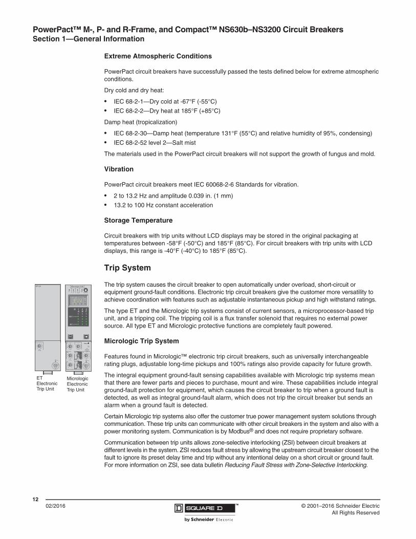
Trip System
The trip system causes the circuit breaker to open automatically under overload, short-circuit or equipment ground-fault conditions. Electronic trip circuit breakers give the customer more versatility to achieve coordination with features such as adjustable instantaneous pickup and high withstand ratings.
The type ET and the Micrologic trip systems consist of current sensors, a microprocessor-based trip unit, and a tripping coil. The tripping coil is a flux transfer solenoid that requires no external power source. All type ET and Micrologic protective functions are completely fault powered.
Micrologic Trip System
Features found in Micrologic™ electronic trip circuit breakers, such as universally interchangeable rating plugs, adjustable long-time pickups and 100% ratings also provide capacity for future growth.
The integral equipment ground-fault sensing capabilities available with Micrologic trip systems mean that there are fewer parts and pieces to purchase, mount and wire. These capabilities include integral ground-fault protection for equipment, which causes the circuit breaker to trip when a ground fault is detected, as well as integral ground-fault alarm, which does not trip the circuit breaker but sends an alarm when a ground fault is detected.
Certain Micrologic trip systems also offer the customer true power management system solutions through communication. These trip units can communicate with other circuit breakers in the system and also with a power monitoring system. Communication is by Modbus® and does not require proprietary software.
Communication between trip units allows zone-selective interlocking (ZSI) between circuit breakers at different levels in the system. ZSI reduces fault stress by allowing the upstream circuit breaker closest to the fault to ignore its preset delay time and trip without any intentional delay on a short circuit or ground fault. For more information on ZSI, see data bulletin Reducing Fault Stress with Zone-Selective Interlocking.
ET
Trip Unit
Micrologic
Trip UnitElectronicElectronic
ET1.0I
test
I iinstantaneous
x In
43
6 8 101215
off2
setting
Micrologic 6.0A
40
100%
%
menu
.4.45.5
.6.63
.7.8.9
1
delay
short I itsd
(s)
on I2t
.2
.3.4 .4
.1
.2.3
.10off
instantaneous
long timealarmIr
x In
ground fault
BC
DE F
GH
J
Ig tg (s)
on I2t
.2
.3.4 .4
.1
.2.3
.10off
A
.512
48
121620
tr(s)
@ 6 Ir24
settingx Ir
22.5
34 5
68
10
Isd
1.5x In
43
6 8 101215
off2
test
kAs
Ir=Ii=
tr=Isd=
Ig=
tsd=t=
tg=
I n= MAX

PowerPact™ M-, P- and R-Frame, and Compact™ NS630b–NS3200 Circuit BreakersSection 1—General Information
1302/2016™© 2001–2016 Schneider Electric
All Rights Reserved
Communication with a power monitoring system through a communications network allows a ground fault to be reported without interrupting power to the system. It also allows the power monitoring system to remotely report power usage, current flow, and trip history.
Instantaneous OFF Feature
Micrologic™ 5.0 and 6.0 Standard, A, P, and H electronic trip units provide the unique ability to turn the instantaneous tripping function OFF. Turning off the instantaneous trip function increases the current level at which the circuit breaker will trip with no intentional delay to the level of the short-time withstand rating. This current level is typically much higher than any of the pickup levels provided by the adjustable instantaneous feature. Therefore, using the instantaneous OFF feature improves coordination by allowing the user to take advantage of the circuit breaker withstand rating.
Motor Circuit Protectors
An instantaneous trip version of the electronic trip circuit breaker is also available for motor circuit protection. These motor circuit protectors comply with NEC requirements for providing short-circuit protection when installed as part of a Listed combination controller having motor overload protection.
Electronic trip motor circuit protectors are similar in construction to type ET electronic trip circuit breakers.They are designed as disconnect devices for use in combination with motor starters. These motor circuit protectors provide short-circuit protection only and have an adjustable amperage pickup so they can be set to open instantaneously at current values slightly above the motor starting inrush current. This setting coordinates the pickup time-current response of the motor circuit protector with the overload relay of the motor starter to give the best possible protection.
Current interrupting ratings for these UL Recognized components are established in combination with motor starters and properly-sized overload relays and contactors.
Automatic Molded Case Switches
P- and R-frame circuit breakers are also available in automatic molded case switch construction. Automatic switches are similar in construction to electronic trip circuit breakers, except that the switches open instantaneously at a factory-set non-adjustable trip point calibrated to protect only the molded case switch itself. Because of their molded case construction, they are more compact than conventional disconnect switches and accept electrical accessories for added flexibility.
Molded case switches are intended for use as disconnect devices only. UL489 requires molded case switches to be protected by a circuit breaker or fuse of equivalent rating. Molded case switches are labeled with their appropriate withstand ratings. The withstand rating of a switch is defined as the maximum current at rated voltage that the molded case switch will withstand without damage when protected by a circuit breaker with an equal continuous current rating.
Table 8: P- and R-Frame Withstand Ratings1
1 The withstand rating is the fault current at rated voltage that the molded case switch will withstand without damage when protected by a circuit breaker with an equal continuous current rating.
Voltage
Withstand Rating
P-Frame Circuit Breakers R-Frame Circuit Breakers
J K L J K L
240 Vac 100 kA 65 kA 125 kA — 65 kA 125 kA
480 Vac 65 kA 50 kA 100 kA — 50 kA 100 kA
600 Vac 25 kA 50 kA 25 kA — 50 kA 50 kA

PowerPact™ M-, P- and R-Frame, and Compact™ NS630b–NS3200 Circuit Breakers Section 1—General Information
1402/2016 ™ © 2001–2016 Schneider Electric
All Rights Reserved
Internal Operating Mechanism
Manually-Operated Circuit Breakers
M-frame, P-frame, R-frame and NS630b–NS3200 manually-operated circuit breakers have a single operating handle that acts directly through the operating mechanism against the contact blades. Multi-pole circuit breakers have a common trip bar for positive action of all poles on manual and automatic operation. These circuit breakers have a trip-free mechanism that allows them to trip even though the operating handle may be restricted (by a handle operating mechanism or padlock attachment) in the I/ON position. If not restricted, the operating handle moves to a position between I/ON and O/OFF when the circuit breaker is tripped.
The face of the manually-operated circuit breaker is marked with standard ON/OFF and international I/O markings to indicate handle position. In addition, the O/OFF portion of the circuit breaker handle is color coded green.
Electrically-Operated Circuit Breakers
P-frame and NS630b–NS1600 circuit breakers are also available with a two-step stored-energy mechanism which can be charged manually or using a motor. The closing time is less than five cycles. Closing and opening operations can be initiated by remote control or by push buttons on the front cover. An O-C-O (open-close-open) cycle is possible without recharging. Electrically-operated circuit breakers include a motor, shunt trip, and shunt close of the same voltage plus an overcurrent trip switch (SDE).
The face of electrically-operated circuit breakers is also marked ON/OFF and I/O, and equipped with a position indicator to show contact position.
Push-to-Trip Button
The push-to-trip button located on the face of each manually-operated circuit breaker is a standard feature on these circuit breakers. This allows the user to manually trip the circuit breaker without risking exposure to live parts. During normal on-off operation, the handle opens and closes the circuit breaker contact but does not exercise the tripping mechanism.
Use the push-to-trip button to:
• Exercise the circuit breaker mechanism
• Check the auxiliary and alarm switch circuits
Circuit Breaker Mounting and Connections
Table 9: Circuit Breaker Mounting and Connections
Circuit BreakerUnit-Mount Construction I-Line
ConstructionDrawout
ConstructionCable Connection Bus Connection
M-Frame X X X —
P-Frame X X X X
R-Frame X1
1 Must use RLTB or RL3TB terminal pad kit.
X X2
2 Through 1200 A, 100% rated only.
—
NS630b–NS1250 X X — X
NS1600–NS3200 — X — —

PowerPact™ M-, P- and R-Frame, and Compact™ NS630b–NS3200 Circuit BreakersSection 1—General Information
1502/2016™© 2001–2016 Schneider Electric
All Rights Reserved
Unit-Mount Circuit Breakers
Unit-mount M-frame, P-frame, R-frame and NS630b–NS3200 circuit breakers are individually-mounted using supplied mounting screws. The four mounting screws are inserted through mounting holes molded into the circuit breaker case and threaded into the circuit breaker mounting enclosure. To properly support the circuit breaker, all four mounting screws must be used.
Unit-mount M-frame, P-frame and NS630b–NS1250 circuit breakers can be ordered with mechanical line and load side lugs. The standard lugs can be removed for the installation of compression-type lugs or bus connections. All lugs are UL Listed for their proper application and marked for use with aluminum and copper (Al/Cu) or copper only (Cu) conductors. Lugs suitable for copper and aluminum conductors are made of tin-plated aluminum. Lugs suitable for use with copper conductors only are made of copper.
See individual frame sections for frame-specific connection information.
I-Line Circuit Breakers
M-frame circuit breakers through 800 A and P-frame and R-frame circuit breakers through 1200 A are available in I-Line construction for easy installation and removal in I-Line panelboards and switchboards. I-Line circuit breakers use “blow-on” type line side connectors. In case of a short circuit, increased magnetic flux causes the plug-on connectors of the circuit breaker to tighten their grasp on the panelboard or switchboard bus bars. The I-Line connectors and circuit breaker mounting bracket are integral parts of I-Line circuit breakers and cannot be removed or replaced. I-Line circuit breakers come with mechanical load side lugs.
Drawout Circuit Breakers
P-frame manually-operated circuit breakers and switches are also available in drawout construction. The drawout assembly mechanism allows the circuit breaker to be racked in four positions (connected, test, disconnect or withdrawn).
P-frame cradles are ordered separately and are available with factory and field-installed accessories. See Section 10—P-Frame Cradles and Cradle Accessories for details.
M-Frame Unit-Mount P-Frame Unit-Mount R-Frame Unit-MountElectrically Operated P-Frame Unit-Mount
P-Frame I-LineM-Frame I-Line R-Frame I-Line
P-Frame Drawout

PowerPact™ M-, P- and R-Frame, and Compact™ NS630b–NS3200 Circuit Breakers Section 1—General Information
1602/2016 ™ © 2001–2016 Schneider Electric
All Rights Reserved
Catalog Numbering System
The M-frame, P-frame, R-frame and NS630b–NS3200 circuit breakers and cradles follow a “smart” catalog numbering system. The following tables are intended as a tool to decipher existing catalog numbers. They are not intended for use in building catalog numbers, as some combinations may not be available. To build a catalog number, please see the Digest, the Product Selector or contact the local field office.
M-Frame, P-Frame and R-Frame Circuit Breaker Catalog Numbers
NOTE: Not all options are available on all frames.
Table 10: Catalog Number for M-, P- and R-Frame (UL/IEC Dual-Rated) Circuit Breakers
Field Position Field Description Options Description
1 Brand Name(blank) Square D
N Schneider Electric (Formerly Merlin Gerin brand)
2 Circuit Breaker Frame
M 800 A Max.
P 1200 A Max.
R 3000 A Max.
3 Interrupting Rating
G 35 kA @ 480 Vac
J 65 kA @ 480 Vac
K P-Frame: 50 kA @ 600 VacR-Frame: 65 kA @ 600 Vac
L 100 kA @ 480 Vac
4 Connection
F No Lugs
L Lugs on Both Ends
M Lugs on I/ON End
P Lugs on O/OFF End
A I-Line
D Drawout (Not Available on M and R Frames)
5 Poles
2 2P
3 3P
4 4P
6 Voltage Rating4 480 V
6 600 V
7–9 Ampere Rating### Circuit Breaker Rating (120 = 1200 A)
000 Automatic Switch Value
10 Standard or 100% Rated(none) Standard Rated
C 100% rated
Continued on next page

PowerPact™ M-, P- and R-Frame, and Compact™ NS630b–NS3200 Circuit BreakersSection 1—General Information
1702/2016™© 2001–2016 Schneider Electric
All Rights Reserved
11–14
Circuit Breaker Trip System
(none) ET1.0 (M-Frame)
(none) ET1.0I (P-Frame, R-Frame)
U31 Micrologic™ 3.0 Trip Unit
U33 Micrologic 5.0 Trip Unit
U41 Micrologic 3.0A Trip Unit
U43 Micrologic 5.0A Trip Unit
U44 Micrologic 6.0A Trip Unit
U63 Micrologic 5.0P Trip Unit
U64 Micrologic 6.0P Trip Unit
U73 Micrologic 5.0H Trip Unit
U74 Micrologic 6.0H Trip Unit
Automatic Switch Trip System1
S60 600 A2
S80 800 A2
S10 1000 A2
S12 1200 A
S16 1600 A
S20 2000 A
S25 2500 A
S30 3000 A
Motor Circuit Protector Trip System
M68 1200–10000 A2
M69 1500–10000 A2
M70 1800–10000 A2
15 Rating Plug A–H See Table 80
16-17 Modbus® Communication E1 Modbus BCM
18 I-Line™ Phasing See Digest, Product Selector
For Factory-Installed Accessories, See Product Selector
1 For more information on P-frame switches, see page 78. For more information on R-frame switches, see page 89.2 Not available on R-frame.
Table 10: Catalog Number for M-, P- and R-Frame (UL/IEC Dual-Rated) Circuit Breakers
Field Position Field Description Options Description

PowerPact™ M-, P- and R-Frame, and Compact™ NS630b–NS3200 Circuit Breakers Section 1—General Information
1802/2016 ™ © 2001–2016 Schneider Electric
All Rights Reserved
NS630b–NS3200 Circuit Breaker Catalog Numbers
Table 11: Catalog Number for NS630b–NS3200 (IEC-Rated) Circuit Breakers
Field Position Field Description Options Description
1 Brand Name(Blank) Square D
N Schneider Electric
2 Circuit Breaker FrameR 3200 A Max.
P 1600 A Max.
3 Interrupting Rating
N Standard Interrupting Rating
H High Interrupting Rating
L Current Limiting
R1
1 R interruption only valid with rear-connected (S) termination.
200 kA Interrupting
4 Connection
F No lugs
L Lugs on Both Ends
M Lugs on I/ON End
P Lugs on O/OFF End
D Drawout
S Rear Connected
5 Certification E IEC
6 Poles3 3P
4 4P
7 Voltage Rating4 440 Vac
6 690 Vac
8–10 Ampere Rating### Circuit Breaker Rating (120 = 1200 A)
000 Switch Value
11–14 Circuit Breaker Trip System
U32 Micrologic™ 2.0 Trip Unit
U33 Micrologic 5.0 Trip Unit
U42 Micrologic 2.0A Trip Unit
U43 Micrologic 5.0A Trip Unit
U44 Micrologic 6.0A Trip Unit
U63 Micrologic 5.0P Trip Unit
U64 Micrologic 6.0P Trip Unit
U73 Micrologic 5.0H Trip Unit
U74 Micrologic 6.0H Trip Unit
Non-Automatic Switch Trip System
Z63 630 A
Z80 800 A
Z10 1000 A
Z12 1250 A
Z16 1600 A
15 Rating Plug R–T See Table 79
16–17 Modbus® Communications E1 Modbus BCM
For Accessories, See Product Selector

PowerPact™ M-, P- and R-Frame, and Compact™ NS630b–NS3200 Circuit BreakersSection 1—General Information
1902/2016™© 2001–2016 Schneider Electric
All Rights Reserved
Cradle Catalog Numbers
P-frame and NS630b–NS1600 manually-operated circuit breakers and switches are available in drawout construction (factory installed only). The circuit breakers may be ordered using the circuit breaker catalog numbering systems described above. The cradles must be ordered separately.
Table 12: Cradle Catalog Number
Field Position Field Description Options Description
1 Cradle C Cradle
2 Frame SizeS P-Frame 3P
D P-Frame 4P
3 Brand/CertificationL Square D Brand UL/IEC Dual-Rated
G Schneider Electric IEC Rated Only
4 Circuit Breaker Interruption Rating E P-Frame “G”,“J”, “K”, or “L” Interrupting Rating
5 Cradle Connections Top Terminals
V Rear-Connected T Vertical (RCTV)
H Rear-Connected T horizontal (RCTH)
E Front-Connected Flat (FCF)
6 Cradle Connections Bottom Terminals
V Rear-Connected T Vertical (RCTV)
H Rear-Connected T Horizontal (RCTH)
E Front-Connected Flat (FCF)
7 Shutters and Associated Options9 None (Standard for P-Frame Circuit Breakers)
3 Shutters with Padlocking Provision
8 Circuit Breaker Mismatch and Cradle Interlock A See Product Selector
9 Metering CT X Not Applicable on P-Frame Cradle
10 Cradle Secondary Disconnects Wiring X See Product Selector
11–18 Miscellaneous Cradle Options X See Product Selector

PowerPact™ M-, P- and R-Frame, and Compact™ NS630b–NS3200 Circuit Breakers Section 1—General Information
2002/2016 ™ © 2001–2016 Schneider Electric
All Rights Reserved
Testing Requirements
UL, NEMA, CSA, and NMX requirements
The UL, NEMA, CSA and NMX labels on a circuit breaker indicate that the circuit breaker meets the requirements of UL Standard 489, NEMA Standard AB-1, CSA Standard C22.2 No. 5 and NMX standard J266. The labels also mean that the production procedure is monitored by UL, CSA and ANCE inspectors to ensure continued compliance to these standards. These requirements include the following tests:
• 200% Overload Calibration—each pole of the circuit breaker must trip within a specified time limit when carrying 200% of its continuous current rating.
• 135% Overload Calibration—with all poles connected in series, the circuit breaker must trip within a specified time limit while carrying 135% of its continuous current rating.
• Overload—the circuit breaker must make and break 600% of its continuous current rating at rated voltage. Circuit breaker frame sizes 125–1600 A must perform 50 operations at 600%. Circuit breaker frame sizes 2000–2500 A must perform 25 operations at 600%.
• Temperature Rise—while carrying 100% of rated current and mounted in open air, temperature rise on a wiring terminal must be within specified limits. For 100% rating, the circuit breaker is mounted in an enclosure.
• Endurance—UL489 requires that the circuit breaker must complete, at minimum, the following number of operations:
• Calibration—both the 200% and 135% overload calibration tests are repeated after endurance testing.
• Short Circuit—the circuit breaker shall be subjected to test currents based on voltage rating and frame size, with the type and number of operations based on the number of poles, frame rating and voltage rating. Example: a 3P, 600 Vac, 2500 A frame circuit breaker is subjected to one 20 kA single-phase closing of the circuit on the circuit breaker per pole and one 30 kA three-phase closing of the circuit on the circuit breaker for a total of seven short circuit tests.
• Trip Out—the 200% thermal calibration test is repeated following the short-circuit tests.
• Dielectric—the circuit breaker must withstand, for one minute, twice its rated voltage plus 1000 V:
— Between line and load terminals with the circuit breaker in the open, tripped and OFF positions.
— Between terminals of opposite polarity with the circuit breaker closed.
— Between live parts and the overall enclosure with the circuit breaker both open and closed.
No conditioning of the circuit breaker can take place during or between tests. There can be no failure of functional parts at the conclusion of the sequences.
After qualifying a set of circuit breakers to the standard tests, a manufacturer can have additional circuit breaker samples tested on higher than standard available fault currents. The following performance requirements apply:
• 200% Overload Calibration—each pole of the circuit breaker must trip within a specified time limit when carrying 200% of its continuous current rating.
• Short-Circuit Test—with the load side terminals connected by 10-inch lengths of specified cable (or a shorting bar), the circuit breaker is exposed to a short-circuit current for a set time interval. After safe interruption, the circuit breaker is reset and closed again on the short circuit.
• 250% Overload Calibration—each pole of the circuit breaker must trip within a specified time limit when carrying 250% of its continuous current rating.
Table 13: Endurance Operations
Frame SizeOperations
With Current 1 Without Current
1200–2500 500 2000
1 UL requires the circuit breaker to operate 10% of the “with current” operations with a shunt trip.

PowerPact™ M-, P- and R-Frame, and Compact™ NS630b–NS3200 Circuit BreakersSection 1—General Information
2102/2016™© 2001–2016 Schneider Electric
All Rights Reserved
• Dielectric Withstand—the circuit breaker is subjected to twice the voltage rating at which the interrupting test was conducted, but not less than 900 V.
— Between line and load terminals with the circuit breaker in the tripped and in the OFF positions.
— Between terminals of opposite polarity with the circuit breaker closed.
— Between live parts and the overall enclosure with the circuit breaker both open and closed.
When the sample circuit breakers pass these tests, circuit breakers of the same construction can be marked or labeled with the current interrupting rating for the higher fault currents.
IEC Requirements
The IEC markings on a circuit breaker indicates that the circuit breaker meets the requirements of IEC Standard 60947-2 for circuit breakers and 60947-3 for automatic switches. These requirements include the following tests:
Table 14: IEC Test Sequence
Sequence Category of Devices Tests
General Performance Characteristics(Sequence 1)
All Circuit Breakers
• Tripping Limits and Characteristics• Dielectric Properties• Mechanical and Electrical Endurance• Overload• Dielectric Voltage Withstand• Temperature Rise• 145% Calibration (3 Poles in Series or 3-Phase Test)
Rated Service Short-circuit Breaking Capacity (Ics) (Sequence 2)
All Circuit Breakers
• Rated service short circuit breaking capacity (O-t-CO-t-CO)• Electrical Endurance (5% of with Current Operations of
Sequence 1)• Dielectric Voltage Withstand• Temperature Rise• 145% Calibration (3 poles in series or 3-phase test)
Rated Ultimate Short-circuit Breaking Capacity (Icu) (Sequence 3)
Circuit Breakers of Utilization Category A
Circuit Breakers of Utilization Category B
• 200% Calibration (Each Pole Separately)• Rated Ultimate Short Circuit Breaking Capacity (O-t-CO)• Dielectric Voltage Withstand• 250% Calibration (Each Pole Separately)
Rated Short-time Withstand Current (Icw) (Sequence 4)
Circuit Breakers of Utilization Category B
• 200% Calibration (Each Pole Separately)• Rated Short-Time Withstand Current • Temperature Rise• Short-Circuit Breaking Capacity at Maximum Short-Time
Withstand Current (O-t-CO)• Dielectric Voltage Withstand• 200% Calibration (Each Pole Separately)
Combined Sequence
Circuit Breakers of Utilization Category B:
When Icw = Ics Replaces Sequences 2 and 4
When Icw = Ics = Icu Replaces Sequences 2, 3 and 4
• 200% Calibration (Each Pole Separately)• Rated Short-Time Withstand Current Icw• Rated Service Short-Circuit Breaking Capacity at Ics
(O-CO-CO) at Maximum Relay Temp.• 145% Calibration (3 Poles in Series or 3-Phase Test)• Dielectric Voltage Withstand• Temperature Rise• 200% Calibration (Each Pole Separately)
Individual Pole Short-Circuit Test Sequence (Annex H)
Circuit Breakers for Use in IT Systems• Individual Pole Short-Circuit Breaking Capacity• Dielectric Voltage Withstand• 250% Calibration (Each Pole Separately)

PowerPact™ M-, P- and R-Frame, and Compact™ NS630b–NS3200 Circuit Breakers Section 2—Energy Management
2202/2016 ™ © 2001–2016 Schneider Electric
All Rights Reserved
Section 2—Energy Management
Energy Management Using the Smart System
Use the Smart System to connect your building to real savings in three steps:
A. Measure
Embedded and stand-alone metering and control
B. Connect
— Integrated communication interfaces
— Ready to connect to energy management platforms
C. Save
— Data-driven energy efficiency actions
— Real-time monitoring and control
— Access to energy and site information through on-line services
CLOUD

PowerPact™ M-, P- and R-Frame, and Compact™ NS630b–NS3200 Circuit BreakersSection 2—Energy Management
2302/2016™© 2001–2016 Schneider Electric
All Rights Reserved
Measure
Smart System communications mean visible information.
Grouping most of the electrical protection, command and metering components, the switchboards are now significant sources of data locally displayed and sent via communication networks.
Connect
Smart Systems use reliable, simple-to-install-and-use displays, and Ethernet and Modbus interfaces.
Information is safely transmitted through the most efficient networks:
— Modbus SL inside switchboards, between components,
— Ethernet, on cable or WiFi, inside the building and connecting switchboards and computers,
— Ethernet or GPRS, for access to on-line services by Schneider Electric.
Energy experts, no matter where they are located, can now provide advise based on the updated data of the building.
Save
On-Site Real-Time Monitoring and Control
The FDM128 touch screen display connected to the Ethernet:
• shows essential electrical information and alarms concerning the electrical network,
• allows control (open, close, reset…) of various equipment.
The FDM128 touch screen provides real-time value checking and control, directly on the front panel of the main switchboard.
On a PC display with common browser:
• shows monitoring web pages hosted into the local Ethernet interface,
• alarm events generate automatic email notifications,
• allows control (open, close, reset…) of various equipment.
The data is displayed graphically or recorded into files for optimizing the use of energy in the building.
As an example, the data can help validate the change of temperature settings, time scheduling in a Building Management System or other automated devices.
On-Line Energy Management Services
StruXureWare Energy Operation automates data collection using an open, scalable, and secure energy management information system.
With the help of the Schneider Electric energy management services team, data is turned into information to enable customers to understand their facilities’ performance on an ongoing basis.
Energy Operation leverages companies’ current investments in their existing systems, and can be used to communicate advanced results and performance to a broad audience for a shared understanding throughout an organization.
CLOUD

PowerPact™ M-, P- and R-Frame, and Compact™ NS630b–NS3200 Circuit Breakers Section 2—Energy Management
2402/2016 ™ © 2001–2016 Schneider Electric
All Rights Reserved
Smart System Communication Components
PowerPact and Compact Circuit Breakers with Micrologic Trip Units
Ammeter A
• 2.0 basic protection (IEC)
• 3.0 basic protection (UL)
• 5.0 selective protection
• 6.0 selective + ground-fault protection
Power Meter P
• 5.0 selective protection
• 6.0 selective + ground-fault protection
Harmonic Meter H
• 5.0 selective protection
• 6.0 selective + ground-fault protection
See page 40 for more information.
Displays
FDM121
• One-to-one front display module
• See page 25 for more information
FDM128
• One-to-eight front display module
• See page 25 for more information
Communication
• PowerPact and Compact circuit breakers in a communication network
• I/O application module
• IFE: Ethernet interface module
• IFM: Modbus interface module
• Com’X 200: Energy server
Power Meter
Operating Assistance Functions
Communication
IFE Module IFM ModuleI/O Module
Com’X 200

PowerPact™ M-, P- and R-Frame, and Compact™ NS630b–NS3200 Circuit BreakersSection 2—Energy Management
2502/2016™© 2001–2016 Schneider Electric
All Rights Reserved
See page 54 for more information.
Power Meter Functions
In addition to protection functions, Micrologic A/P/H trip units offer all the functions of Power Meter products as well as operating assistance for the circuit breaker.
Micrologic A/P/H trip unit measurement functions are made possible by the Micrologic trip unit’s intelligence and the accuracy of the sensors. They are handled by a microprocessor that operates independent of protection functions.
Display Function
FDM121 Display Unit (One to One)
The FDM121 switchboard display unit can be connected to a communication (COM) option (Breaker Communication Module [BCM ULP]) using a circuit breaker ULP cord to display all measurements on a screen. The LCD screen is 3.78 x 3.78 in. (96 x 96 mm). The FMD121 display unit requires a 24 Vdc power supply. The COM option (BCM ULP) unit is supplied by the same power supply via the circuit breaker ULP cord connecting it to the FDM121. See page 30 for more information.
FDM128 Display Unit (One to Eight)
The FDM128 display unit uses an IFE Ethernet interface for low-voltage circuit breakers.
For all FDM, in addition to the information displayed on the Micrologic trip unit LCD, the FDM screen shows demand, power quality, and maximum/minimum ammeter values along with histories and maintenance indicators.
Display Function
Alarms
ServicesESC OK
Main Menu
Quick view
Control
Metering
I1I
%
310 A I2
%
315 A
I3
%
302 A IN
%
23 A
ESC ESC
U1
U2
U3
V 4/7
402 V 100 120%
398 V 100 120%
401 V 100 120%
ESC
P 64 kW
Q 38 kVar
S 51 kVA
PQS
ESC
Ep 14397 kWh
Eq 8325 kVarh
Es 13035 kVAh
E
FDM121 Display Navigation
FDM121 Display:Consumption
FDM121 Display:Power
FDM121 Display:Voltage
FDM121 DisplayCurrent
20.12.2011 12:00:05
S1-1 - Lighting/Level1
Quick view
Measures
Alarm history
Control
Maintenance
ESC 1/7
Quick view Open Auto
I1 A000Ir A000
20.12.2011 12:00:05
S1-1 - Lighting/Level1
Measures
Alarm history
Control
Maintenance
ESC 1/7
Quick view Open Auto
I1 A000Ir A000
20.12.2011 12:00:05
S1-1 - Lighting/Level1
Quick view
Measures
Alarm history
Control
Maintenance
ESC
I1 AI2 AI3 AIN A
431385426
2
EPQSU-VI
Measures
1/10
I Current
20.12.2011 12:00:05
S1-1 - Lighting/Level1
Quick view
Alarm history
Control
Maintenance
ESC
I1 AI2 AI3 AIN A
431385426
2
EPQSU-VI
Measures
1/10
I CurrentI Current
20.12.2011 12:00:05
S1-1 - Lighting/Level1
Quick view
Measures
Alarm history
Control
Maintenance
ESC
V12 VV23 VV31 V
406415409
1/10
EPQSU-VIVL-L
Measures
20.12.2011 12:00:05
S1-1 - Lighting/Level1
Quick view
Alarm history
Control
Maintenance
ESC
V12 VV23 VV31 V
406415409
1/10
EPQSU-VIVL LVL-L
Measures
20.12.2011 12:00:05
S1-1 - Lighting/Level1
Quick view
Measures
Alarm history
Control
Maintenance
ESC
Ptot kWQtot kVAr
12713
Stot kVA129
1/12
EPQSU-VIPQS
Measures
20.12.2011 12:00:05
S1-1 - Lighting/Level1
Quick view
Alarm history
Control
Maintenance
ESC
Ptot kWQtot kVAr
12713
Stot kVA129
1/12
EPQSU-VIPQSPQS
Measures
20.12.2011 12:00:05
S1-1 - Lighting/Level1
Quick view
Measures
Alarm history
Control
Maintenance
ESC
EpIn kWhEpOut kWh
16545
EPQSU-VIE cumul
1/3
Measures Reset
20.12.2011 12:00:05
S1-1 - Lighting/Level1
Quick view
Alarm history
Control
Maintenance
ESC
EpIn kWhEpOut kWh
16545
EPQSU-VIE cumulE cumul
1/3
Measures Reset
FDM128 Display Navigation
FDM128 Display:Consumption
FDM128 Display:Power
FDM128 Display:Voltage
FDM128 DisplayCurrent

PowerPact™ M-, P- and R-Frame, and Compact™ NS630b–NS3200 Circuit Breakers Section 2—Energy Management
2602/2016 ™ © 2001–2016 Schneider Electric
All Rights Reserved
Measurement Function
Instantaneous RMS Measurements
The Micrologic trip unit continuously displays the RMS value of the highest current of the three phases and neutral (Imax). The navigation buttons can be used to scroll through the main measurements.
In the event of a fault trip, the trip cause is displayed.
The Micrologic A trip unit measures phase, neutral, and ground fault currents.
Micrologic P/H trip units offer voltage, power, power factor, frequency, and cos in addition to the measurements provided by Micrologic A trip units.
Maximum / Minimum Ammeter
Every instantaneous measurement provided by Micrologic A trip units can be associated with a maximum/minimum ammeter. The maximum for the highest current of the three phases, neutral, and demand current can be reset using the FDM display unit or the communication system.
Energy Metering
The Micrologic P/H trip units also measures the energy consumed since the last reset of the meter. The active energy meter can be reset using the Micrologic trip unit keypad, the FDM display unit, or the communication system.
Demand and Maximum Demand Values
Micrologic P/H trip units also calculate demand current and power values. These calculations can be made using a block or sliding interval that can be set from five to sixty minutes in steps of one minute. The window can be synchronised with a signal sent through the communication system. Whatever the calculation method, the calculated values can be recovered on a PC through the communication network.
Ordinary spreadsheet software can be used to provide trend curves and forecasts based on this data. They provide a basis for load shedding and reconnection operations used to adjust consumption to the subscribed power.
Power Quality
The Micrologic H trip unit calculates power quality indicators taking into account the presence of harmonics up to the fifteenth harmonic, including the total harmonic distortion (THD) of current and voltage.
Measurement Function

PowerPact™ M-, P- and R-Frame, and Compact™ NS630b–NS3200 Circuit BreakersSection 2—Energy Management
2702/2016™© 2001–2016 Schneider Electric
All Rights Reserved
Table 15: Micrologic A/P/H Trip Units Integrated Power Meter Functions
Micrologic A/P/H Integrated Power Meter Functions Type
Display
Micrologic LCD
FDM Display
Display of protection settings
Pick-ups (A) and delays All settings can be displayed Ir, tr, Isd, tsd, Ii, Ig, tg A/P/H X —
Measurements
Instantaneous rms measurements
Currents (A)
Phases and neutral
Average of phases
Highest current of the 3 phases and neutral
Ground fault (Micrologic 6)
Current unbalance between phases
IA, IB, IC, IN
Iavg = (IA + IB + IC) / 3
Imax of IA, IB, IC, IN
% Ig (pick-up setting)
% Iavg
A/P/H
A/P/H
A/P/H
A/P/H
P/H
X
—
X
X
—
X
X
X
X
X
Voltages (V)
Phase-to-phase
Phase-to-neutral
Average of phase-to-phase voltages
Average of phase-to-neutral voltages
Ph-Ph and Ph-N voltage unbalance
Phase sequence
VAB, VBC, VCA
VAN, VBN, VCN
Vavg = (VAB + VBC + VCA) / 3
Vavg = (VAN + VBN + VCN) / 3
% Vavg
ABC, ACB
P/H
P/H
P/H
P/H
P/H
P/H
X
X
—
—
—
X
X
X
X
X
X
X1
Frequency (Hz) Power system f P/H X X
Power
Active (kW)P, total
P, per phase
P/H
P/H
X
X
X
X
Reactive (kVAR) Q, total
Q, per phase
P/H
P/H
X
X
X
X
Apparent (kVA)S, total
S, per phase
P/H
P/H
X
X
X
X
Power Factor PF, total
PF, per phase
P/H
P/H
X
X
X
X
os Cos , total
Cos , per phase
P/H
P/H
X
X
X
X
Maximum/Minimum Ammeter Associated with instantaneous rms measurements
Reset using the FDM display unit and Micrologic keypad A/P/H X X
Energy Metering
Energy Energy Active (kW), reactive (kVARh), apparent (kVAh) Total since last reset P/H X X
Demand and Maximum Demand Values
Demand Current (A) Phases and neutral PPresent value on the selected window
Maximum demand since last reset
P/H
P/H
X
X
X
X
Demand Power Active (kWh), reactive (kVAR), apparent (kVA)Present value on the selected window
Maximum demand since last reset
P/H
P/H
X
X
X
X
Calculation Window Sliding, fixed or com-synchronised Adjustable from 5 to 60 minutes in 1 minute steps2 P/H — —
Power Quality
Total Harmonic Distortion (%)
Of voltage with respect to rms value THDU,THDV of the Ph-Ph and Ph-N voltage H X X
Of current with respect to rms value THDI of the phase current H X X
1 FDM121 only.2 Available via the communcation system only.

PowerPact™ M-, P- and R-Frame, and Compact™ NS630b–NS3200 Circuit Breakers Section 2—Energy Management
2802/2016 ™ © 2001–2016 Schneider Electric
All Rights Reserved
Histories
• Trip indications in clear text in a number of user-selectable languages
• Time-stamping: date and time of trip.
Maintenance Indicators
Micrologic trip units have indicators for, among other items, the number of operating cycles, load profile, and operating times (operating hours counter).
It is possible to assign an alarm to the operating cycle counter to plan maintenance.
The various indicators can be used together with the trip histories to analyze the level of stresses the device has been subjected to.
Contact Wear
Contact wear algorithms only function on Masterpact circuit breakers , and contact wear cannot be selected for PowerPact or Compact circuit breakers.
Each time a Masterpact circuit breaker opens, the Micrologic P/H trip unit measures the interrupted current and increments the contact-wear indicator as a function of the interrupted current, according to test results stored in memory. Breaking under normal load conditions results in a very slight increment. The indicator value may be read on the FDM display.
It provides an estimation of contact wear calculated on the basis of the cumulative forces affecting the circuit breaker. When the indicator reaches 100%, it is advised to visually inspect the contacts per the instructions in the circuit breaker user guide.
Circuit Breaker Load Profile
Micrologic A/P/H trip units calculate the load profile of the circuit breaker protecting a load circuit. The profile indicates the percentage of the total operating time at four current levels (% of circuit breaker In):
• 0 to 49% In
• 50 to 79% In
• 80 to 89% In
• 90% In.
This information can be used to optimize use of the protected equipment or to plan ahead for maintenance interval extensions.

PowerPact™ M-, P- and R-Frame, and Compact™ NS630b–NS3200 Circuit BreakersSection 2—Energy Management
2902/2016™© 2001–2016 Schneider Electric
All Rights Reserved
Management of Installed Devices
Each circuit breaker equipped with a COM option (BCM ULP) can be identified using the communication system:
• serial number
• firmware version
• hardware version
• device name assigned by the user.
This information together with the previously described indications provides a clear description of the installed devices.
Table 16: Micrologic A/P/H Trip Units Operating Assistance Functions
Micrologic A/P/H Operating Assistance Functions Type
Display
Micrologic LCD
FDM Display
Operating Assistance
Trip History
Trips Cause of tripping Ir, Isd, Ii, Ig, IDn A/P/H X X
Maintenance Indicators
Counter
Mechanical cycles
Electrical cycles
Hours
Assignable to an alarm
Assignable to an alarm
Total operating time (hours)1
A/P/H
A/P/H
A/P/H
—
—
—
X
X
—
Indicator Contact wear % P/H X X
Load Profile Hours at different load levels% of hours in four current ranges: 0-49% In, 50-79% In, 80-89% In and 90% In P/H — X
1 Available through the communication system only.

PowerPact™ M-, P- and R-Frame, and Compact™ NS630b–NS3200 Circuit Breakers Section 2—Energy Management
3002/2016 ™ © 2001–2016 Schneider Electric
All Rights Reserved
FDM121 Display
Micrologic trip unit measurement capabilities come into full play with the FDM121 display. It connects to the COM option (BCM ULP) with a circuit breaker ULP cord and displays the Micrologic trip unit information. The result is a true integrated unit combining a circuit breaker and a power meter. Additional operating assistance functions can also be displayed.
An FDM121 display unit can be connected to ULP communication devices using a prefabricated cord to display all measurements, alarms, histories and event tables, maintenance indicators, and management of installed devices on a screen.
The FMD121 display unit requires a 24 Vdc power supply.
The FDM121 is a display that can be integrated with the PowerPact H/J/L/P/R or Masterpact NW/NT circuit breaker systems. It uses the sensors and processing capacity of the Micrologic trip unit. It is easy to use and requires no special software or settings. It is immediately operational when connected to the circuit breaker by a ULP cord.
It also provides monitoring and control with the use of the I/O application module, the motor mechanism module, or the circuit breaker communication module (BCM ULP).
The FDM121 has a large display, but requires very little depth. The anti-glare graphic screen is backlit for very easy reading even under poor ambient lighting and at sharp angles.
Display of Micrologic Trip Unit Measurements and Alarms
The FDM121 is intended to display Micrologic trip unit measurements, alarms and operating information. It cannot be used to modify the protection settings.
Measurements can be easily accessed using a menu. All user-defined alarms are automatically displayed. The display mode depends on the priority level selected during alarm set-up:
• high priority: a pop-up window displays the time-stamped description of the alarm and the orange Alarm LED flashes;
• medium priority: the orange Alarm LED goes continuously on;
• low priority: no display on the screen.
All faults resulting in a trip automatically produce a high-priority alarm, without any special settings required. In all cases, the alarm history is updated. The Micrologic trip unit saves the information in its non-volatile memory in the event of an FDM121 power loss.

PowerPact™ M-, P- and R-Frame, and Compact™ NS630b–NS3200 Circuit BreakersSection 2—Energy Management
3102/2016™© 2001–2016 Schneider Electric
All Rights Reserved
Status Indications and Remote Control
When the circuit breaker is equipped with the Breaker Communications Module (BCM ULP), the FDM121 display can also be used to view circuit breaker status conditions:
• O/F: ON/OFF
• SD: trip indication
• SDE: fault-trip indication (overload, short-circuit, or ground fault).
When the circuit breaker system is equipped with the I/O application module, the FDM121 can monitor and control:
• cradle management
• circuit breaker operation
• light and load control
• custom applications.
When the circuit breaker is equipped with the COM option (BCM ULP) (including connection to shunt close [XF] and shunt trip [MX1] communication voltage releases), the FDM121 display can also be used to control (open/close) the circuit breaker.
Two operating mode are available:
• local mode: open/close commands are enabled from the FDM121 while disabled from the communication network;
• remote mode: open/close commands are disabled from the FDM121 while enabled from the communication network.
Main Characteristics
• A 3.78 x 3.78 x 1.18 in. (96 x 96 x 30 mm) screen requiring 0.39 in. (10 mm) behind the door (or 0.79 in. [20 mm] when the 24 V power supply connector is used).
• White backlighting.
• Wide viewing angle: vertical ±60°, horizontal ±30°.
• High resolution: excellent reading of graphic symbols.
• Alarm LED: flashing orange for alarm pick-up, steady orange after operator reset if the alarm condition persists.
• Operating temperature range: +14°F (-10°C) to +131°F (+55°C).
• CE / UL / CSA marking.
• 24 Vdc power supply, with tolerances 24 V -20% (19.2 V) to 24 V +10% (26.4 V).
When the FDM121 is connected to the communication network, the 24 Vdc can be supplied by the communication system wiring system. Consumption is 40 mA.
Mounting
The FDM121 is easily installed in a switchboard.
• Standard door cut-out is 3.6 x 3.6 in. (92 x 92 mm).
• Attached using clips.
To avoid a cut-out in the door, an accessory is available for surface mounting by drilling only two 0.87 in. (22 mm) diameter holes.
FDM121 Display
Surface Mount Accessory
Connection with FDM121 Display Unit

PowerPact™ M-, P- and R-Frame, and Compact™ NS630b–NS3200 Circuit Breakers Section 2—Energy Management
3202/2016 ™ © 2001–2016 Schneider Electric
All Rights Reserved
Connection
The FDM121 is equipped with a 24 Vdc terminal block:
• A plug-in type terminal block with two wire inputs per point for easy daisy-chaining.
• A power supply range of 24 Vdc -20% (19.2 V) to 24 Vdc +10% (26.4 V).A 24 Vdc type auxiliary power supply must be connected to a single point on the ULP system. The FDM121 display has a two-point screw connector on the rear panel of the module for this purpose. The ULP module to which the auxiliary power supply is connected distributes the supply via the ULP cable to all the ULP modules connected to the system and therefore also to Micrologic trip unit. See wiring diagram later in this section.
• Two RJ45 jacks.
The Micrologic trip unit connects to the internal communication terminal block on the PowerPact or Compact circuit breaker with the circuit breaker ULP cord. Connection to one of the RJ45 connectors on the FDM121 automatically establishes communication between the Micrologic trip unit and the FDM121 and supplies power to the Micrologic trip unit measurement functions.
When the second connector is not used, it must be fitted with a line terminator.
Navigation
Five buttons are used for intuitive and fast navigation.
The “Context” button may be used to select the type of display (digital, bargraph, analogue).
The user can select the display language (Chinese, English, French, German, Italian, Portuguese, Spanish, etc.).
Screens
Main Menu
When powered up, the FDM121 screen automatically displays the ON/OFF status of the device.
When not in use, the screen is not backlit. Backlighting can be activated by pressing one of the buttons. It goes off after three minutes.
I1I
%
310 A I2
%
315 A
I3
%
302 A IN
%
23 A
1 3 4 5 62
ESC
Micrologic 5.3AProduit Id
Serial number:
Part number:
Firmware:
P07451
LU432091
1.02
ESC
ESC OK
I
U-V
PQS
E
F - PF - cos F
Metering
ESC
EpIN 5111947 kWh
EpOut 12345678 kWh
NonResettableEnergy 1/3
ESC
0..49%
50...79%
80..89%
90..100%
610 H
2/3
15 H
360 H
3 H
Load Profile
1 Escape2 Down3 OK4 Up5 Context6 Alarm LED
Product Identification Metering: Submenu Metering: Meter Services
Quick View Metering Control Alarms Services

PowerPact™ M-, P- and R-Frame, and Compact™ NS630b–NS3200 Circuit BreakersSection 2—Energy Management
3302/2016™© 2001–2016 Schneider Electric
All Rights Reserved
Fast Access to Essential Information
• “Quick view” provides access to five screens that display a summary of essential operating information (I, U-V, f, P, E, THD, circuit breaker ON/OFF).
Access to Detailed Information
• “Metering” can be used to display the measurement data (I, U-V, f, P, Q, S, E, THD, PF) with the corresponding min/max values.
• “Alarms” displays active alarms and the alarm history.
• “Services” provides access to the operation counters, energy and maximum ammeter reset function, maintenance indicators, identification of modules connected to the internal bus, and FDM121 internal settings (language, contrast, etc.).
Communication Components and FDM121 Connections
The FDM121 degree of protection is IP54 in front. IP54 is maintained after switchboard mounting by using the supplied gasket during installation.
Figure 1: FDM121 Connections
LV434195 LV434196 LV434197
Circuit Breaker ULP Cord
0.98 ft.(0.35 m)
4.3 ft.(1.3 m)
9.8 ft.(3 m)
ETH1 ETH2
24VDC
+ -
External power supply24 Vdc
B’ / R
x + D1
A’ / Rx - D
0
B / Tx + D
1
A / Tx - D0
0 V
24 V
E1
Red Black Blue
OR
E2 E3 E4 E5 E6
Customer Terminal Block
White
IFM
+ -
External power supply24 Vdc
IFE
D0 = A’ / Rx-, A / Tx-D1 = B’ / Rx+, B / Tx+
Ethernet
B’ / R
x + D1
A’ / Rx - D
0
B / Tx + D
1
A / Tx - D0
0 V
24 V
E1
Red Black Blue
E2 E3 E4 E5 E6
Customer Terminal Block
White
Modbus-SL
AB
C
D
F C
D
FE E
A. Modbus NetworkB. Ethernet NetworkC. Circuit Breaker ULP CordD. FDM DisplayE. ULP TerminationF. ULP Cable
ConnectionsPowerPact and Compact circuit breakers are connected to the ULP devices (FDM121 display, IFM, IFE or I/O unit) via the circuit breaker ULP cord.
• Cord is available in three lengths: 0.98 ft. (0.35 m), 4.3 ft. (1.3 m) and 9.8 ft. (3 m).
• Lengths up to 32.9 ft. (10 m) are possible using extensions.
A
C
D
E
F
B
C
D
F
E

PowerPact™ M-, P- and R-Frame, and Compact™ NS630b–NS3200 Circuit Breakers Section 2—Energy Management
3402/2016 ™ © 2001–2016 Schneider Electric
All Rights Reserved
FDM128 Display
The Micrologic trip unit measurement capabilities are fully utilized with the FDM128 display. The FDM128 display connects to Ethernet communication using the RJ45 port and displays Micrologic trip unit information. The result is an integrated unit combining a circuit breaker with a power meter. Additional operating assistance functions can also be displayed.
The FDM128 display unit can be connected to a Micrologic COM option (BCM ULP through an IFE). It uses the sensors and processing capacity of the Micrologic trip unit and requires no special software or settings. The FDM128 is a large display, but requires very little depth. The anti-glare graphic screen is backlit for easy reading even under poor ambient lighting and at sharp angles.
The FDM128 display is designed to manage up to eight devices (PowerPact H/J/L/P/R or Masterpact NW/NT circuit breakers).
Display of Micrologic Trip Unit Measurements and Trips
The FDM128 is intended to display Micrologic A/P/H trip unit measurements, trips, and operating information. It cannot be used to modify the protection settings.
• Measurements may be easily accessed using a menu.
• Trips are automatically displayed.
• A pop-up window displays the time-stamped description of the trip.
Status Indications
When the circuit breaker is equipped with the COM option (BCM ULP) (including its set of sensors) the FDM128 display can also be used to view circuit breaker status conditions:
• O/F: ON/OFF
• SDE: Fault-trip indication (overload, short-circuit, ground fault)
• PF: ready to close
• CH: charged (spring loaded).
• CE, CD, CT cradle management with I/O application module.
Remote Control
When the circuit breaker is equipped with the COM option (BCM ULP) (including connection to shunt close [XF] and shunt trip [MX1] communication voltage releases), the FDM128 display can also be used to operate (open/close) the circuit breaker.
Two operating mode are available:
• Local mode: open/close commands are enabled from the FDM128 while disabled from the communication network.
• Remote mode: open/close commands are disabled from the FDM128 while enabled from the communication network.

PowerPact™ M-, P- and R-Frame, and Compact™ NS630b–NS3200 Circuit BreakersSection 2—Energy Management
3502/2016™© 2001–2016 Schneider Electric
All Rights Reserved
Main Characteristics
• 4.54 x 3.40 in. (115.2 x 86.4 mm) with 5.7 in. (145 mm) QVGA display 320 x 240 pixels.
• Color TFT LCD, with LED backlight.
• Wide viewing angle: vertical ±80°, horizontal ±70°.
• High resolution: excellent reading of graphic symbols.
• Operating temperature range: +14°F (-10°C) to +131°F (+55°C).
• CE / UL / CSA marking.
• 24 Vdc power supply, -10%/+20% (limit 20.4 - 28.8 Vdc).
• Consumption 6.8 W.
Mounting
The FDM128 is easily installed in a switchboard.
• Standard door hole Ø 0.87 in. (22 mm).
• The FDM128 degree of protection is IP65 at the touch screen cover. IP54 is maintained after installation by using the supplied gasket.
Connection
The FDM128 is equipped with:
• a 24 Vdc terminal block:
— power supply range of 24 Vdc (limit 20.4 - 28.8 Vdc).
— The FDM128 display unit has a 2-point screw connector on the rear panel of the module for this purpose.
• One RJ45 Ethernet jacks.
The Micrologic trip unit connects to the internal communication terminal block on the Masterpact circuit breakers through the circuit breaker ULP cord and Ethernet connection through the IFE.
Navigation
• A touch screen is used for intuitive and fast navigation.
• The user can select the display language (Chinese, English, French, German, Italian, Portuguese, Spanish, etc.).
Screens
Main Menu
When not in use, the screen is automatically shifted to low back-lighting.
FDM128 Display
Surface Mount Accessory
Connection with Display Unit
20.12.2011 12:00:05
S1-1 - Lighting/Level1
Quick view
Measures
Alarm history
Control
Maintenance
ESC
Maintenance
3/3
Operation
Trip SDE
Close command
Product ID Information Reset allCounter
xxx
xxx
xxx
20.12.2011 12:00:05
S1-1 - Lighting/Level1
Quick view
Measures
Alarm history
Control
ESC
Maintenance
3/3
Operation
Trip SDE
Close command
Product ID Information Reset allCounterCounter
xxx
xxx
xxx
20.12.2011 12:00:05
S1-1 - Lighting/Level1
Quick view
Measures
Alarm history
Control
Maintenance
ESC
Energy
Ep kWhEq kVArhEs kVAh
11 318257
13 815
6/7
Quick view
20.12.2011 12:00:05
S1-1 - Lighting/Level1
Measures
Alarm history
Control
Maintenance
ESC
Energy
Ep kWhEq kVArhEs kVAh
11 318257
13 815
6/7
Quick view
20.12.2011 12:00:05
S1-1 - Lighting/Level1
Quick view
Measures
Alarm history
Control
Maintenance
ESC
Maintenance
0 to 49%
50 to 79%
80 to 89%
2/3
90 to 100%
Product ID Information Reset allLoad profile
20.12.2011 12:00:05
S1-1 - Lighting/Level1
Quick view
Measures
Alarm history
Control
ESC
Maintenance
0 to 49%
50 to 79%
80 to 89%
2/3
90 to 100%
Product ID Information Reset allLoad profileLoad profile
Metering: Meter ServicesProduct Identification
Quick View Metering Control Alarms Services

PowerPact™ M-, P- and R-Frame, and Compact™ NS630b–NS3200 Circuit Breakers Section 2—Energy Management
3602/2016 ™ © 2001–2016 Schneider Electric
All Rights Reserved
Fast Access to Essential Information
• “Quick view” provides access to five screens that display a summary of essential operating information (I, U-V, f, P, E, THD, circuit breaker On / Off).
Access to Detailed Information
• "Metering" can be used to display the measurement data (I, U-V, f, P, Q, S, E, THD, PF) with the corresponding min/max values.
• “Alarms” displays the trip history.
• “Services” provides access to the operation counters, energy and maximum ammeter reset function, maintenance indicators, identification of modules connected to the internal bus and FDM128 internal settings (language, contrast, etc.).
Communication Components and FDM128 Connections
The FDM128 degree of protection is IP65 at the touch screen cover. IP54 is maintained after installation by using the supplied gasket.
Figure 2: FDM128 Connections
D
EC C
D
ELV434195 LV434196 LV434197Circuit Breaker ULP Cord
0.98 ft(0.35 m)
4.3 ft(1.3 m)
9.8 ft(3 m)
A. FDM128B. Ethernet NetworkC. Circuit Breaker ULP CordD. UFEE. ULP Termination
C
B
D
E
ConnectionsPowerPact and Compact circuit breakers are connected to the ULP devices (FDM display, IFM, IFE or I/O unit) via the circuit breaker ULP cord.
• Cord is available in three lengths: 0.98 ft. (0.35 m), 4.3 ft. (1.3 m) and 9.8 ft. (3 m).
• Lengths up to 32.9 ft. (10 m) are possible using extensions.

PowerPact™ M-, P- and R-Frame, and Compact™ NS630b–NS3200 Circuit BreakersSection 2—Energy Management
3702/2016™© 2001–2016 Schneider Electric
All Rights Reserved
Figure 3: Panelboard and Switchboard Connections
PowerPact
ULPULP
Internet (cloud)
FE
E E E
F
D
A
B
C
PowerPact and Compact
Table 17: Smart System Communication Devices and Displays
Name FunctionPort Bin.
InputAnalog.Input
Bin. OutputTo Device To Server
A Com’X 200Energy Server with Ethernet Gateway® Function
Modbus Master Ethernet Cable + WiFI
6 2 —
B FDM128 Ethernet LCD Color Touch Screen
— Ethernet — — —
C FDM121LCD Display for Circuit Breaker ULP — — — —
Continued on next page

PowerPact™ M-, P- and R-Frame, and Compact™ NS630b–NS3200 Circuit Breakers Section 2—Energy Management
3802/2016 ™ © 2001–2016 Schneider Electric
All Rights Reserved
D
IFE Interface + Gateway
Ethernet Interface & Gateway
Modbus Master & ULP Ethernet — — —
IFE Interface Ethernet Interface for Circuit Breakers ULP Ethernet — — —
E IFM Modbus Interface for Circuit Breakers
ULP Modbus Slave — — —
F I/OInput/Output Application Module for Circuit Breakers
ULP ULP 6 1 1
Table 17: Smart System Communication Devices and Displays (continued)
Name FunctionPort Bin.
InputAnalog.Input
Bin. OutputTo Device To Server

PowerPact™ M-, P- and R-Frame, and Compact™ NS630b–NS3200 Circuit BreakersSection 3—Electronic Trip Systems
3902/2016™© 2001–2016 Schneider Electric
All Rights Reserved
Section 3—Electronic Trip Systems
M-frame circuit breakers are available with the type ET 1.0 electronic trip system. P-frame and R-frame circuit breakers are available with either the ET1.0I basic electronic trip system or the Micrologic™ electronic trip system. The NS630b–NS3200 circuit breakers are available with the Micrologic electronic trip system. The sensing system responds to the flow of current through the circuit breaker.
Thermal Imaging
The thermal imaging function protects the cables or bus bars from overheating in case of low amplitude repetitive faults. Such overheating can be due to repetitive motor startings, fluctuating load, intermittent ground faults, or subsequent closing after a fault. Traditional electronic protection does not protect against repetitive faults because the duration of each overload above the pickup setting is too short to achieve effective tripping. Nevertheless, each overload involves a temperature rise in the installation, the cumulative effect of which could lead to overheating of the system.
The thermal imaging function remembers and integrates the thermal heating caused by each pickup setting overrun. Before tripping, the integrated heating value will reduce the associated time delay and, therefore, the reaction of the trip unit will be closer to the real heating of the power network system. After tripping, the function will also reduce the time delay when closing the circuit breaker on an overload.
True RMS Current Sensing
The sensing system responds to the flow of current through the circuit breaker. The trip unit samples the current waveform to provide true RMS protection through the fifteenth harmonic. This true RMS sensing gives accurate values for the magnitude of a non-sinusoidal waveform. Therefore, the heating effects of harmonically distorted waveforms are accurately evaluated.
The Micrologic H trip unit provides additional sampling of the waveforms to measure and provide waveform capture of harmonic distortion to the thirty-first harmonic.
Type ET Electronic Trip System
Type ET trip units are available with M-frame, P-frame and R-frame UL/IEC circuit breakers. Circuit breakers with type ET trip units have a fixed ampere rating. The trip units are not field-interchangeable and will not accept any communications or other trip unit accessories. The trip system uses a set of current transformers (called CTs or sensors) to sense current, a trip unit to evaluate the current, and a tripping solenoid to trip the circuit breaker.
ET1.0 (M-Frame only)
The ET1.0 trip system is available on M-frame circuit breakers and is equipped with fixed long-time and adjustable instantaneous tripping functions only. The long-time pickup is fixed at 1.0 x sensor rating (In), while the instantaneous pickup is adjustable (dial settings from 2–10 x In) with no intentional time delay.
ET1.0I (P-Frame and R-Frame only)
The ET1.0I trip system is available on both P-frame and R-frame circuit breakers and is equipped with fixed long-time and adjustable instantaneous tripping functions only. The long-time pickup is fixed at 1.0 x sensor rating (In), while the instantaneous pickup is adjustable (dial settings from 1.5–12 x In) with no intentional time delay.
ET1.0M (P-Frame only)
The ET1.0M trip system is only available on P-frame motor circuit protectors and provides protection for short circuit conditions only. The trip unit has a single adjustment for instantaneous pickup that, if

PowerPact™ M-, P- and R-Frame, and Compact™ NS630b–NS3200 Circuit Breakers Section 3—Electronic Trip Systems
4002/2016 ™ © 2001–2016 Schneider Electric
All Rights Reserved
exceeded, will trip the circuit breaker with no intentional delay. Instantaneous trip dial settings are 2–16 x In for 600 A circuit breakers and 1.5–12 x In for 800–1200 A circuit breakers.
Micrologic™ Electronic Trip Systems
The P-frame, R-frame and NS630b–NS3200 electronic trip circuit breakers can be equipped with the optional Micrologic trip systems listed below:
Trip units are designed to protect power circuits and loads. Micrologic trip systems use a set of current transformers (called CTs or sensors) to sense current, a trip unit to evaluate the current, and a tripping solenoid to trip the circuit breaker. Adjustable rotary switches on the trip unit allow the user to set the proper overcurrent or equipment ground-fault current protection required in the electrical system. If current exceeds a set value for longer than its set time delay, the trip system opens the circuit breaker. Alarms may be programmed for remote indications. Measurements of current, voltage, frequency, power, and power quality optimize continuity of service and energy management.
Integration of protection functions in the Application Specific Integrated Circuit (ASIC) electronic component used in all Micrologic trip units guarantees a high degree of reliability and immunity to conducted or radiated disturbances. On Micrologic P and H trip units, advanced functions are managed by an independent microprocessor.
Circuit breakers are shipped with the trip unit long-time pickup switch set at 1.0 and all other trip unit adjustments set at their lowest settings. Actual settings required for a specific application must be determined by a qualified consultant or plant engineer. A coordination study is recommended to provide coordination between all circuit breakers in the distribution system.
Table 18: Micrologic Trip Systems
Model
(LS0)Long-time + Short-time + Zero delay(IEC Rated Only)
(LI)Long-time + Instantaneous Protection(UL Listed, IEC Rated)
(LSI)Long-time + Short-time + Instantaneous Protection(UL LIsted, IEC Rated)
(LSIG)Long-time + Short-time + Instantaneous Protection + Equipment Ground-fault Protection (UL LIsted, IEC Rated)
Micrologic Basic Trip Unit 2.0 3.0 5.0 —
Micrologic A Trip Unit 2.0A 3.0A 5.0A 6.0A
Micrologic P Trip Unit — — 5.0P 6.0P
Micrologic H Trip Unit — — 5.0H 6.0H
Table 19: Micrologic™ Trip Unit Features
Feature
Micrologic Trip Unit (X = Standard Feature O = Available Option)
Standard Ammeter Power Harmonics
2.0 3.0 5.0 2.0A 3.0A 5.0A 6.0A 5.0P 6.0P 5.0H 6.0H
Field-Installable X X X X X X X X X X X
LI X X
LS0 X X
LSI X X X X
LSIG/Ground-Fault Trip1 X X X
Ground-Fault Alarm/No Trip1, 2 X X
Ground-Fault Alarm and Trip1, 2 X X
Adjustable Rating Plugs X X X X X X X X X X X
True RMS Sensing X X X X X X X X X X X
UL Listed X X X X X X X X X
Thermal Imaging X X X X X X X X X X X
Continued on next page

PowerPact™ M-, P- and R-Frame, and Compact™ NS630b–NS3200 Circuit BreakersSection 3—Electronic Trip Systems
4102/2016™© 2001–2016 Schneider Electric
All Rights Reserved
Phase-Loading Bar Graph X X X X X X X X
LED for Long-Time Pick-Up X X X X X X X X X X X
LED for Trip Indication X X X X X X X X
Digital Ammeter X X X X X X X X
Zone-Selective Interlocking3 X X X X X X X
Communications O O O O X X X X
LCD Dot Matrix Display X X X X
Advanced User Interface X X X X
Protective Relay Functions X X X X
Neutral Protection1 X X X X
Contact Wear Indication X X X X
Incremental Fine Tuning of Settings X X X X
Selectable Long-Time Delay Bands X X X X
Power Measurement X X X X
Power Quality Measurements X X
Waveform Capture X X
1 3Ø, 4W circuits require either a neutral current transformer or a 4-pole breaker.2 Requires M6C Programmable Contact Module.3 Not available for 2.0A trip units as upstream devices.
Table 19: Micrologic™ Trip Unit Features (continued)
Feature
Micrologic Trip Unit (X = Standard Feature O = Available Option)
Standard Ammeter Power Harmonics
2.0 3.0 5.0 2.0A 3.0A 5.0A 6.0A 5.0P 6.0P 5.0H 6.0H
Micrologic 3.0
.4.45.5
.6.63
.7.8.9
1
x Ir
23
4 5 6810
121.5
setting
Im
.512
48
121620
instantaneous
long timealarmIr tr
(s)
x In @ 6 Ir24
Micrologic 5.0
.4.45.5
.6.63
.7.8.9
1
delay
short I itsd
(s)
on I2t
.2
.3.4 .4
.1
.2.3
.10off
instantaneous
long timealarmIr
x In .512
48
121620
tr(s)
@ 6 Ir24
setting
x Ir
22.5
34 5
68
10
Isd
1.5x In
3
46 8 10
12
15off2
Micrologic 3.0A
40
100%
%
menu
.4.45.5
.6.63
.7.8.9
1
long timealarmIr
x In .512
48
121620
tr(s)
@ 6 Ir24
x Ir
23
4 5 6810
101.5
setting
Iminstantaneous
kAs
Ir=Ii=
tr=Isd=
Ig=
tsd=t=
tg=
I n= MAX
Micrologic 5.0A
40
100%
%
menu
.4.45.5
.6.63
.7.8.9
1
delay
short I itsd
(s)
on I2t 0off
instantaneous
long timealarmIr
x In .512
48
121620
tr(s)
@ 6 Ir24
settingx Ir
22.5
34 5
68
10
Isd
1.5x In
22.5
34 5
68
101.5.2.3
.4 .4
.1
.2.3
.1
kAs
Ir=Ii=
tr=Isd=
Ig=
tsd=t=
tg=
I n= MAX
Micrologic 6.0A
40
100%
%
menu
.4.45.5
.6.63
.7.8.9
1
delay
short I itsd
(s)
on I2t
.2
.3.4 .4
.1
.2.3
.10off
instantaneous
long timealarmIr
x In
ground fault
BC
DE F
GH
J
Ig tg (s)
on I2t
.2
.3.4 .4
.1
.2.3
.10off
A
.512
48
121620
tr(s)
@ 6 Ir24
setting
x Ir
22.5
34 5
68
10
Isd
1.5x In
43
6 8 101215
off2
test
kAs
Ir=Ii=
tr=Isd=
Ig=
tsd=t=
tg=
I n= MAX
Micrologic 3.0A, 5.0A and 6.0A Trip UnitsMicrologic 3.0 and 5.0 Basic Trip Units

PowerPact™ M-, P- and R-Frame, and Compact™ NS630b–NS3200 Circuit Breakers Section 3—Electronic Trip Systems
4202/2016 ™ © 2001–2016 Schneider Electric
All Rights Reserved
•
Micrologic 5.0P
delaysettingx Ir
22.5
34 5
68
10
Isd
1.5
.4.45.5
.6.63
.7.8.9
1
short tsd (s)
on I2t 0off
instantaneous
long timealarmIr
x In .512
48
121620
tr(s)
@ 6 Ir24
85kA
30kA
24s5000A
I(A)Trip
0.4s
.2
.3.4 .4
.1
.2.3
.1
I i
x In2
410
3
6 8
12
15off
Micrologic 6.0P
.4.45.5
.6.63
.7.8.9
1
delay
short tsd (s)
on I2t
.2
.3.4 .4
.1
.2.3
.10off
instantaneous
long timealarmIr
x In
ground fault
BC
DE
GH
J
Ig tg (s)
on I2t
.2
.3.4 .4
.1
.2.3
.10off
A
setting
x Ir
22.5
34 5
68
10
Isd
1.5
.512
48
121620
tr(s)
@ 6 Ir24
test
85kA
30kA
24s5000A
I(A)Trip
0.4s
I i
x In2
410
3
6 8
1215
off
Micrologic 5.0H
delaysettingx Ir
22.5
3 4 568
10
Isd
1.5
.4.45.5
.6 .63 .7.8.9
1
shorttsd(s)
on I2t
.2
.3.4 .4
.1
.2.3
.10off
instantaneous
long timealarmIr
x In .512
4 8 121620
tr(s)
@ 6 Ir24
I (A)V (V)
P (kW)E (kWh)Harmonics
I i
x In2
410
3
6 81215
off
Micrologic 6.0H
.4.45.5
.6.63
.7.8.9
1
delay
short tsd (s)
on I2t
.2
.3.4 .4
.1
.2.3
.10off
instantaneous
long timealarmIr
x In
ground fault
BC
DE
GH
J
Ig tg (s)
on I2t
.2
.3.4 .4
.1
.2.3
.10off
A
settingx Ir
22.5
34 5
68
10
Isd
1.5
.512
48
121620
tr(s)
@ 6 Ir24
test
I (A)
V (V)
P (kW)
E (kWh)
Harmonics
I i
x In2
410
3
6 8
1215
off
Micrologic 5.0H and 6.0H Trip UnitsMicrologic 5.0P and 6.0P Trip Units
Micrologic™ 2.0, 3.0 and 5.0 Basic Trip Units
The Micrologic 2.0, 3.0, and 5.0 basic trip units protect power circuits.
Protection Settings
Protection thresholds and delays are set using the rotary switches. A full-range of long-time settings are available via field-installable adjustable rating plugs.
• Overload protection
— True RMS long-time protection
— Thermal imaging: Active thermal imaging before and after tripping
• Short-circuit protection
— Short-time RMS
— Selection of I2t type (ON or OFF) for short-time delay
• Instantaneous protection
• Neutral protection on four-pole circuit breakers
1
2
.4.5.6
.7.8
.9.95.98
1
delay
short timeI itsd
(s)
on I2
t
.2
.3.4 .4
.1
.2.3
.10off
instantaneous
long timealarmIr
x In
4
5
6
.512
48
121620
tr(s)
@ 6 Ir24
settingx Ir
22.5
34 5
68
10
Isd
1.5x In
3
46 8 10
12
15off2
3
Micrologic 5.0
1—Long-time current setting and tripping delay2—Short-time pickup and tripping delay3—Overload signal (LED)4—Long-time rating plug screw5—Instantaneous pickup6—Test connector
0 I
tIr
tr
Ii
Table 20: Micrologic 2.0 and 3.0 Basic Trip Unit Settings
Long-Time Protection
Current Setting (A)Tripping between 1.05 and 1.20 x Ir
Ir = ln x ...2.0: 0.40 0.50 0.60 0.70 0.80 0.90 0.95 0.98 1.003.0: 0.40 0.45 0.50 0.60 0.63 0.70 0.80 0.90 1.00Other ranges are available by changing rating plug
Maximum Time Delay (s)Accuracy: 0 to –20%
tr at 1.5 x Ir 12.5 25 50 100 200 300 400 500 600tr at 6 x Ir 0.5 1 2 4 8 12 16 20 24tr at 7.2 x Ir 0.34 0.69 1.38 2.7 5.5 8.3 11 13.8 16.6
Thermal Imaging 20 minutes before or after tripping
Short-Time Protection
Current Setting (A)Accuracy: ±10%No delay
Isd = Ir x ... 2.0: 1.5 2 2.5 3 4 5 6 8 10
Instantaneous Protection
Current Setting (A)Accuracy: ±10% Ii = In x ... 3.0: 1.5 2 3 4 5 6 8 10 12

PowerPact™ M-, P- and R-Frame, and Compact™ NS630b–NS3200 Circuit BreakersSection 3—Electronic Trip Systems
4302/2016™© 2001–2016 Schneider Electric
All Rights Reserved
Ir
tr
lsdtsd
li
0 I
t
Table 21: Micrologic 5.0 Basic Trip Unit Settings
Long-Time Protection
Current Setting (A)Tripping Between 1.05 and 1.20 x Ir
Ir = ln x ...
IEC: 0.40 0.50 0.60 0.70 0.80 0.90 0.95 0.98 1.00
UL: 0.40 0.45 0.50 0.60 0.63 0.70 0.80 0.90 1.00
Other Ranges are Available by Changing Rating Plug
Maximum Time Delay (s)Accuracy: 0 to –20%
tr at 1.5 x Ir 12.5 25 50 100 200 300 400 500 600
tr at 6 x Ir 0.5 1 2 4 8 12 16 20 24
tr at 7.2 x Ir 0.34 0.69 1.38 2.7 5.5 8.3 11 13.8 16.6
Thermal Imaging 20 Minutes Before or After Tripping
Short-Time Protection
Current Setting (A)Accuracy: ±10% lsd = Ir x ... 1.5 2 2.5 3 4 5 6 8 10
Maximum Time Delay (s) at 10 x Ir
SettingsI2t OFF 0 0.1 0.2 0.3 0.4
I2t ON 0.1 0.2 0.3 0.4
tsd
Min. Trip Time (ms) 20 80 140 230 350
Max. Trip Time (ms) 80 140 200 320 500
Instantaneous Protection
Current Setting (A)Accuracy: ±10%
Ii = In x ... 2 3 4 6 8 10 12 15 off

PowerPact™ M-, P- and R-Frame, and Compact™ NS630b–NS3200 Circuit Breakers Section 3—Electronic Trip Systems
4402/2016 ™ © 2001–2016 Schneider Electric
All Rights Reserved
Micrologic™ 2.0A, 3.0A, 5.0A and 6.0A Trip Units with Ammeter
Micrologic A trip units protect power circuits and provide current measurements, overload protection, and short-circuit protection. In addition, the 6.0A trip units also provide ground-fault protection for equipment.
Protection Settings
Protection thresholds and delays are set using the rotary switches. The selected values are momentarily displayed in amperes and in seconds. A full-range of long-time settings are available via the field-installable rating plug:
• Overload protection (true RMS long-time protection)
• Thermal imaging (active thermal imaging before and after tripping)
• Short-circuit protection:
— Short-time RMS
— I2t ON or OFF for short-time delay
• Instantaneous protection
• Ground-fault protection for equipment:
— Residual ground-fault protection for equipment
— Source ground-return ground-fault protection for equipment
— Modified differential ground-fault protection (MDGF) for equipment
• Neutral protection on four-pole circuit breakers
• ZSI: Zone-selective interlocking:
— ZSI terminal block may be used to interconnect a number of trip units to provide total discrimination for short-time and equipment ground-fault protection, without delay for tripping).
— Not available for 3.0A trip units or for 2.0A trip units installed as upstream devices.
Ammeter Measurements
Micrologic A trip units measure the true RMS value of currents. They provide continuous current measurement from 0.2 to 20 x In with an accuracy of 1.5% (including sensors). No auxiliary source is needed where I > 0.2 x In. The optional external power supply (24 Vdc) makes it possible to display currents where I < 0.2 x In and to store values of the interrupted current.
A digital LCD screen continuously displays the most heavily loaded phase (Imax) or displays the IA, IB, IC, Ig, and (on 4P circuit breakers only) IN stored current and setting values by successively pressing the navigation button.
Communication Network
In conjunction with an optional communication network, the trip unit transmits the following parameters:
• Setting values
• All ammeter measurements
• Tripping causes
Micrologic 6.0 A
40
100%
%
menu
.4.5.6
.7.8
.9.95.98
1
delay
short timeI itsd
(s)
on I2t
.2
.3.4 .4
.1
.2.3
.10off
instantaneous
long timealarmIr
x In
ground fault
BC
DE F
GH
J
Ig tg(s)
on I2t
.2
.3.4 .4
.1
.2.3
.10off
A
.512
48
121620
tr(s)
@ 6 Ir24
settingx Ir
22.5
34 5
68
10
Isd
1.5x In
test
2
410
3
6 8
1215
off
kAs
Ir=Ii=
tr=Isd=
Ig=
tsd=t=
tg=
I n= MAX
1
12
4
5
103
2
11
9
7
8
6
13
1—Indication of tripping cause2—Navigation buttons3—Long-time current setting and tripping delay4—Short-time pickup and tripping delay5—Ground-fault pickup and tripping delay6—Test lamp and reset7—Digital display8—Three-phase bar graph and ammeter9—Overload signal (LED)10—Long-time rating plug screw11—Instantaneous pickup12—Electronic push-to-trip13—Test connector

PowerPact™ M-, P- and R-Frame, and Compact™ NS630b–NS3200 Circuit BreakersSection 3—Electronic Trip Systems
4502/2016™© 2001–2016 Schneider Electric
All Rights Reserved
External Power Supplies for Micrologic Trip Units
Current-based protection functions require no auxiliary power source.
0 I
tIr
tr
Ii
Table 22: Micrologic 2.0A and 3.0A Trip Unit Settings
Long-Time Protection
Current Setting (A)Tripping Between 1.05 and 1.20 x Ir
Ir = ln x...
2.0A: 0.40 0.50 0.60 0.70 0.80 0.90 0.95 0.98 1.00
3.0A: 0.40 0.45 0.50 0.60 0.63 0.70 0.80 0.90 1.00
Other Ranges are Available by Changing Rating Plug
Maximum Time Delay (s)Accuracy: 0–20%
tr at 1.5 x Ir 12.5 25 50 100 200 300 400 500 600
tr at 6 x Ir 0.5 1 2 4 8 12 16 20 24
tr at 7.2 x Ir 0.34 0.69 1.38 2.7 5.5 8.3 11 13.8 16.6
Thermal Imaging 20 Minutes Before or After Tripping
Short-Time Protection
Current Setting (A)Accuracy: ±10%, No delay Isd = Ir x... 2.0A: 1.5 2 2.5 3 4 5 6 8 10
Instantaneous Protection
Current Setting (A)Accuracy: ±10%
Ii = In x... 3.0A: 1.5 2 3 4 5 6 8 10 12
Ir
tr
lsdtsd
li
0 I
t
Table 23: Micrologic 5.0A and 6.0A Trip Unit Settings
Long-Time Protection
Current Setting (A)Tripping Between 1.05 and 1.20 x Ir
Ir = ln x...
IEC: 0.40 0.50 0.60 0.70 0.80 0.90 0.95 0.98 1.00
UL: 0.40 0.45 0.50 0.60 0.63 0.70 0.80 0.90 1.00
Other ranges are available by changing rating plug
Maximum Time Delay (s)Accuracy: 0–20%
tr at 1.5 x Ir 12.5 25 50 100 200 300 400 500 600
tr at 6 x Ir 0.5 1 2 4 8 12 16 20 24
tr at 7.2 x Ir 0.34 0.69 1.38 2.7 5.5 8.3 11 13.8 16.6
Thermal Imaging 20 minutes before or after tripping
Short-Time Protection
Current Setting (A)Accuracy: ±10% lsd = Ir x... 1.5 2 2.5 3 4 5 6 8 10
Maximum Time Delay (s)at 10 x Ir
SettingsI2t OFF 0 0.1 0.2 0.3 0.4
I2t ON 0.1 0.2 0.3 0.4
tsdMin. trip time (ms) 20 80 140 230 350
Max. trip time (ms) 80 140 200 320 500
Instantaneous Protection
Current Setting (A)Accuracy: ±10% Ii = In x... 2 3 4 6 8 10 12 15 off
0 I
t
lg
tgI2 t off
I2t on
Table 24: Micrologic 6.0A Trip Unit Ground-Fault Settings
Ground-Fault Pickup (A)Accuracy: ±10%
Ig = ln x... A B C D E F G H J
ln ≤ 400 A 0.3 0.3 0.4 0.5 0.6 0.7 0.8 0.9 1.0
400 A < ln ≤ 1200 A 0.2 0.3 0.4 0.5 0.6 0.7 0.8 0.9 1.0
ln > 1200 A 500 640 720 800 880 960 1040 1120 1200
Maximum Time Delay (s) at 1 x Ig
SettingsI2t OFF 0 0.1 0.2 0.3 0.4
I2t ON 0.1 0.2 0.3 0.4
tgMinimum Trip Time (ms) 20 80 140 230 350
Maximum Trip Time (ms) 80 140 200 320 500
Table 25: Micrologic A Use of External 24 Vdc Power Supply
Function Without 24 Vdc Power Supply at F1 and F2 With 24 Vdc Power Supply at F1 and F2
Fault Protection for LSIG Functions Yes Yes
LED Trip Indication Yes Yes
Ammeter and bar graph displays Yes Yes
Trip Setting and Max. Current Readings Can Be Accessed on the Display by Using Navigation Buttons
Yes, If Current Flow on One Phase is Equal To or Greater Than:
Yes
Sensor Plug Value (In) Minimum Ground-fault Pickup
100–250 A 30% of sensor rating
Ground-Fault Push-to-Trip Button Works for Testing Ground Fault1
400–1200 A 20% of sensor rating
1600–6300 A 500 A
Modbus® Communications (Optional) No Yes, with separate 24 Vdc power supply for the circuit breaker communication module
Back-lit Display No Yes
1 Ground fault Push-to-trip button will also be functional if hand-held test kit or full-function test kit is powering the trip unit.

PowerPact™ M-, P- and R-Frame, and Compact™ NS630b–NS3200 Circuit Breakers Section 3—Electronic Trip Systems
4602/2016 ™ © 2001–2016 Schneider Electric
All Rights Reserved
Micrologic™ 5.0P and 6.0P Trip Units with Power Metering
Load Shedding and Reconnection Parameters
Load shedding and reconnection parameters can be set according to the power or the current flowing through the circuit breaker. Load shedding is carried out by a remote computer via the communication network or by an M6C programmable contact.
Micrologic P trip units provide power metering and extended protection in addition to the adjustable protection functions of the Micrologic A trip unit.
Protection Settings
The adjustable protection functions of the 5.0P and 6.0P trip units are identical to those of Micrologic A trip unit (overloads, short circuits, equipment ground-fault protection; see page 44). These units also feature:
• Fine adjustment
Within the range below the rotary switch setting, fine adjustments of pickups/delays in steps of 1 A/s (except for short-time and ground-fault) are possible on the keypad or remotely by the communication network.
• Inverse definite minimum time lag (IDMTL) setting.
Coordination with fuse-type or medium-voltage protection systems is optimized by adjusting the long-time delay curve around 6 x Ir axis. This setting ensures better coordination with certain loads.
• Neutral protection
On three-pole circuit breakers, neutral protection may be set using the keypad or remotely using the communication network to one of four positions: OFF, 1/2N (1/2 x In), 1N (1 x In), or 1.6N (2 x In).
NOTE: Neutral protection is disabled if long-time curve is set to one of the IDMTL protection settings.
• Configuring Alarms and Other Protection Functions
When the cover is closed, the keypad may no longer be used to change the protection settings, but it still provides access to the displays for measurements, histories, indicators, etc. Depending on the thresholds and time delays set, the Micrologic P trip unit monitors current, voltage, power, frequency, and phase sequence. Each threshold overrun may be signalled remotely via the communication network.
Each threshold overrun may be combined with tripping (protection) or an indication carried out by an optional M6C programmable contact (alarm), or both (protection and alarm).
Maintenance Record
The maintenance record can be consulted using the full-function test kit or remotely via the communication network. It can be used as an aid in troubleshooting and to assist scheduling for device maintenance operations. Recorded indications include:
• Highest current measured
• Operation counter (cumulative total and total since last reset)
• Number of test kit connections
• Number of trips in operating mode
Micrologic 6.0 P
.4.5.6
.7.8
.9.95.98
1
delay
short timeI itsd
(s)
on I2t
.2
.3.4 .4
.1
.2.3
.10off
instantaneous
long timealarmIr
x In
ground fault
BC
DE F
GH
J
Ig tg(s)
on I2t
.2
.3.4 .4
.1
.2.3
.10off
A
settingx Ir
22.5
34 5
68
10
Isd
1.5
.512
48
121620
tr(s)
@ 6 Ir24
x In
test
2
410
3
6 8
1215
off
10
8
1
4
715
5
16
12
13
146
9
2
3 11
85kA
30kA
24s5000A
I(A)Trip
0.4s
1—Indication of tripping cause2—High resolution screen3—Measurement display4—Navigation buttons5—Long-time current setting and tripping delay6—Short-time pickup and tripping delay7—Hole for settings lockout pin8—Ground-fault pickup and tripping delay9—Test lamp and indication reset10—Maintenance indicators11—Protection settings12—Overload signal (LED)13—Long-time rating plug screw14—Instantaneous pickup15—Electronic push-to-trip16—Test connector

PowerPact™ M-, P- and R-Frame, and Compact™ NS630b–NS3200 Circuit BreakersSection 3—Electronic Trip Systems
4702/2016™© 2001–2016 Schneider Electric
All Rights Reserved
Indication Option Via Programmable Contacts
The M6C programmable contact may be used to signal threshold overruns or status changes. It can be programmed using the keypad on the Micrologic P trip unit or remotely using the communication network. The contact is required to obtain data from the protective relay functions on Type P and Type H trip units.
Micrologic P trip units are designed to be used with an external 24 Vdc power supply. Current-based protection functions require no auxiliary power source.
I0
t
tr
Ir
IDMTLIsd
tsd
Ii
Ir Isd Ii
Table 26: Micrologic 5.0P and 6.0P Trip Unit Settings
Long-Time (RMS)Protection
Current Setting (A)Tripping Between 1.05 and 1.20 x Ir
Ir = ln x... IEC 0.40 0.50 0.60 0.70 0.80 0.90 0.95 0.98 1.00
Ir = ln x... UL 0.40 0.45 0.50 0.60 0.63 0.70 0.80 0.90 1.00
Other Ranges are Available by Changing Rating Plug
Maximum Time Delay (s)Accuracy: 0 to –20%
tr at 1.5 x Ir 12.5 25 50 100 200 300 400 500 600
tr at 6 x Ir 0.5 1 2 4 8 12 16 20 24
tr at 7.2 x Ir 0.34 0.69 1.38 2.7 5.5 8.3 11 13.8 16.6
IDMTL Setting Curve slope SIT VIT EIT HV Fuse DT
Thermal Imaging 20 Minutes Before or After Tripping
Short-Time (RMS) Protection
Current Setting (A)Accuracy: ±10% lsd = Ir x... 1.5 2 2.5 3 4 5 6 8 10
Maximum Time Delay (s)at 10 x Ir
SettingsI2t OFF 0 0.1 0.2 0.3 0.4
I2t ON 0.1 0.2 0.3 0.4
tsdMin. Trip Time (ms) 20 80 140 230 350
Max. Trip Time (ms) 80 140 200 320 500
Instantaneous Protection
Current Setting (A)Accuracy: ±10% Ii = IN x... 2 3 4 6 8 10 12 15 off
0 I
t
lg
tgI2 t off
I2t on
Table 27: Micrologic 6.0P Trip Unit Ground-Fault Settings
Ground-Fault Pickup (A)Accuracy: ±10%
Ig = ln x... A B C D E F G H J
ln ≤ 400 A 0.3 0.3 0.4 0.5 0.6 0.7 0.8 0.9 1.0
400 A < ln ≤ 1200 A 0.2 0.3 0.4 0.5 0.6 0.7 0.8 0.9 1.0
ln > 1200 A 500 640 720 800 880 960 1040 1120 1200
Time Delay (s) at 1 x In
SettingsI2t OFF 0 0.1 0.2 0.3 0.4
I2t ON 0.1 0.2 0.3 0.4
tgMin. Trip Time (ms) 20 80 140 230 350
Max. Trip Time (ms) 80 140 200 320 500
Table 28: Micrologic 5.0P and 6.0P Trip Unit Settings for Protection Functions
Threshold Time Delay
CurrentCurrent Imbalance 0.05 to 0.6 x Imax 1 to 40 s
Maximum Current Imax: IA, IB, IC, IN, Ig 0.2 to 1.0 x In 15 to 1500 s
Voltage
Voltage Imbalance 0.02 to 0.3 x Vn 1 to 40 s
Minimum Voltage Vmin 100 to 725 V (Phase Total) 0.25 to 0.5 s
Maximum Voltage Vmax 100 to 1200 V (Between Phases) 0.20 to 5.0 s
PowerMaximum Power Pmax 5 to 500 kW 0.2 to 20 s
Reverse Power Pr 0.02 to 0.2 x Pn 0.5 to 20 s
FrequencyMinimum Frequency Fmin 45 to 65 Hz 0.2 to 5 s
Maximum Frequency Fmax 45 to 540 Hz 0.2 to 5 s
Phase Sequence ΔØ ØA-ØB-ØC or ØA-ØC-ØB Instantaneous
Table 29: Micrologic 5.0P and 6.0P Trip Unit Settings for Current and Power Load-Shedding
Pickup Drop-out
Threshold Time Delay Threshold Time Delay
Current I 0.5 to 1.0 x Ir Per Phase 20% to 80% x tr 0.3 to 1.0 x Ir per phase 10 to 600 s
Power P 200 kW to 10 MW 10 to 3600 s 100 kW to 10 MW 10 to 3600 s

PowerPact™ M-, P- and R-Frame, and Compact™ NS630b–NS3200 Circuit Breakers Section 3—Electronic Trip Systems
4802/2016 ™ © 2001–2016 Schneider Electric
All Rights Reserved
Tripping and Alarm Histories
The last ten trips and ten alarms are recorded in two separate history files that can be displayed on the screen (sample displays are shown).
The following information is contained in these files:
Metering
The Micrologic P trip unit calculates in real time the electrical values V, A, W, VAR, VA, Wh, VARh, VAh, Hz, power factor and crest factor. It also calculates demand current and power over an adjustable time period.
Table 30: Micrologic P Use of External 24 Vdc Power Supply
FunctionWithout 24 Vdc Power Supply at F1 and F2
With 24 Vdc Power Supply at F1 and F2
Fault Protection for LSIG Functions Yes Yes
LED Trip Indication Yes Yes
LCD Display and Backlight are Functional Yes1 Yes
Ground-Fault Push-to-Trip Button Works for Testing Ground Fault2 Yes1 Yes
Metering, Monitoring, and History Logs are Functional Yes1 Yes
Communications Between Trip Unit and M2C and M6C Programmable Contact Modules No Yes
Operation of M6C Programmable Contact Module No Yes, with separate 24 Vdc power supply for the module
Modbus Communications NoYes, with separate 24 Vdc power supply for the circuit breaker communication module
1 If circuit breaker has 100 Vac or more between two phases or phase to neutral and is bottom fed or closed in a top fed application.2 Ground-fault push-to-trip button will also be functional if hand-held test kit or full-function test kit is powering the trip unit.
Trip History Alarm History
• Type of fault • Type of alarm
• Date and time of fault • Date and time of alarm
• Interrupted current• Values measured at time of alarm
Trip History Alarm History
Triphistory
30/06/1999Vmax
27/07/1999Isd
03/08/1999Ir
I1 = 4800 A
I2 = 5600 A
I3 = 4000 A
IN = 200 A
03/08/1999
Ir = 4000 A
11:04:18 am
Trip
85kA
30kA
24s5000 A
I(A)Trip
0.4s
Imax
IA = 4800 A IB = 4600 A
IC = 4000 A
IN = 200 A
I = 13 A
instant.
Current Metering Maximum Current
Vinst.
VAB = 460 VVBC = 464 VVCA = 461 V
VAN = 270 VVBN = 279 VVCN = 273 V
Pinst.
P (kW)2180
Q (kVAR)- 650
S (kVA)2280
Voltage Metering Power Metering
F (Hz)
60.0
Pdemand
P (kW)2180
Q (kVAR)- 650
S (kVA)2280
Frequency Power Demand

PowerPact™ M-, P- and R-Frame, and Compact™ NS630b–NS3200 Circuit BreakersSection 3—Electronic Trip Systems
4902/2016™© 2001–2016 Schneider Electric
All Rights Reserved
Real-Time Metering
The value displayed on the screen is refreshed every second. Minimum and maximum measurement values are stored in memory.
Demand Metering
The demand is calculated over a fixed or sliding time window that can be programmed from five to sixty minutes. Depending on the contract signed with the power supplier, specific programming makes it possible to avoid or minimize the cost of overrunning the subscribed power. Maximum demand values are systematically stored and time stamped.
Communication Network
The communication network may be used to:
• Remotely read parameters for the protection functions.
• Transmit all the measurements and calculated values.
• Signal the causes of tripping and alarms.
• Consult the history files and the maintenance indicator record.
In addition, an event log of the last 100 events and a maintenance record, which is stored in the trip unit memory but not available locally, may be accessed via the communication network.
This Modbus communication system is compatible with the Powerlogic™ System Manager™ software (SMS).
Event Log
The event log may be accessed by a remote computer via the communication network. All events are time stamped and include:
• Trips
• Beginning and end of alarms
• Modifications to settings and parameters
• Loss of time
• Test kit connections
• Counter resets
• System faults (thermal self-protection, major fault and minor fault alarms)
Table 31: Real-Time Metering
Type of Measurement Unit of Measurement Measurement Source
Current
IRMS
IAVERAGE
IPEAK/√ 2
A
A
A
ØA, ØB, ØC or N
(ØA + ØB + ØC) / 3
ØA, ØB, ØC or N
Voltage
VRMS
VRMS
ΔVIMBALANCE
V
V
%
(ØA–ØB), (ØB–ØC) and (ØC–ØA)
(ØA–N), (ØB–N) and (ØC–N)
VRMS
Power
P, Q and S
EP, EQ and ES
Power factor
W, VAR, VA
Wh, VARh, VAh
Total
Total
Total
Frequency F Hz 50/60
Table 32: Demand Metering
Type of Measurement Unit of Measurement Measurement Source
Current IDEMAND A ØA, ØB, ØC or N
Power P, Q and SDEMAND W, VAR, VA Total

PowerPact™ M-, P- and R-Frame, and Compact™ NS630b–NS3200 Circuit Breakers Section 3—Electronic Trip Systems
5002/2016 ™ © 2001–2016 Schneider Electric
All Rights Reserved
Micrologic™ 5.0H and 6.0H Trip Units with Harmonic Metering
• Demand Metering: Similar to the Micrologic P trip unit, demand values are calculated over a fixed or sliding time window that can be set from five to sixty minutes.
Waveform Capture
The Micrologic H trip units can capture and store current and voltage waveforms using digital sampling techniques similar to those used in oscilloscopes. Using the information available in the captured waveform, it is possible to determine the level of harmonics as well as the direction and amplitude of the flow of harmonic power.
The Micrologic™ H trip unit can record manually via the keypad the following waveforms:
• Currents IA, IB, IC and IN• Phase-to-phase voltages VAB, VBC, and VCA
In addition to the P functions, the Micrologic H trip units offer:
• In-depth analysis of power quality including calculation of harmonics and the fundamentals.
• Diagnostics aid and event analysis through waveform capture.
• Customized alarm programming to analyze and track down a disturbance on the ac power system.
• Systematic time stamping of all events and creation of logs.
Metering
The Micrologic H trip unit offers all the measurements carried out by the Micrologic P trip unit, with the addition of phase-by-phase measurements of power and energy as well as calculation of:
• Current and voltage total harmonic distortion (THD, thd)
• Current, voltage and power fundamentals (50/60 Hz)
• Harmonic components (amplitude and phase) up to the 31st current and voltage harmonic
• Real-time metering: The value displayed on the screen is refreshed every second. The table below shows what is measured in real-time metering
Table 33: Measurements
Type of Measurement Unit of Measurement Measurement Source
Current
IRMS
IAVERAGE
IPEAK/√2ΔIIMBALANCE
A
A
A
%
ØA, ØB, ØC or N
(ØA + ØB + ØC) / 3
ØA, ØB, ØC or N
ØA, ØB, ØC or N
Voltage
VRMS
VRMS
ΔVIMBALANCE
V
V
%
(ØA–ØB), (ØB–ØC) and (ØC–ØA)
(ØA–N), (ØB–N) and (ØC–N)
VRMS
Power
P, Q and S
EP, EQ and ES
Power factor
W, VAR, VA
Wh, VARh, VAh
Total
Total
Total
Frequency F Hz ØA, ØB, or ØC
Power Quality Indicators
Fundamentals
THD
V and I harmonics
50/60 Hz component
%
Amplitude to phase
V, I, P, Q, and S
V/I
1, 2, 3, 4...50
Micrologic 6.0 H
.4.5.6
.7.8
.9.95.98
1
delay
short timeI itsd
(s)
on I2t
.2
.3.4 .4
.1
.2.3
.10off
instantaneous
long timealarmIr
x In
lg(s)
on I2t
.2
.3.4 .4
.1
.2.3
.10off
settingx Ir
22.5
34 5
68
10
Isd
1.5
.512
48
121620
tr(s)
@ 6 Ir24
x In
test
I (A)
V (V)
P (kW)
E (kWh)
Harmonics
2
410
3
6 8
1215
off
ground fault
BC
DE F
GH
JA
Ig
Table 34: Demand Metering
Type of Measurement Unit of Measurement Measurement Source
Current IDEMAND A ØA, ØB, ØC or N
Power P, Q and SDEMAND W, VAR, VA Total

PowerPact™ M-, P- and R-Frame, and Compact™ NS630b–NS3200 Circuit BreakersSection 3—Electronic Trip Systems
5102/2016™© 2001–2016 Schneider Electric
All Rights Reserved
Waveforms may be displayed on the graphic screen of the control unit or communicated over a networked system. The recording takes place over one cycle with a measurement range of 1 to 1.5 In for current and 0 to 690 volts for voltage. Resolution is 64 points per cycle.
Customized Alarm Programming
The instantaneous value of each measurement can be compared to user-set high and low thresholds. Overrun of a threshold generates an alarm. Programmable action can be linked to each alarm, including circuit breaker opening, activation of an M6C contact, recording of measurements in a log, etc.
Event Logs
Each event is recorded with:
• The date, time, and name of the event
• The event characteristics
Micrologic H trip units are designed to be used with an external 24 Vdc power supply. Current-based protection functions require no auxiliary power source.
Additional Characteristics for Type P and H Trip Units
• Setting the display language: System messages can be displayed in six different languages (English - US, English - UK, French, German, Spanish, and Italian). The desired language is selected via the keypad.
• Protection functions: All current-based protection functions require no auxiliary source. Voltage-based protection functions are connected to ac power via a voltage measurement input built into the circuit breaker on the bottom side. (Optional external voltage measurement is available as a factory-installed option.)
• Accuracy of measurements (including sensors):
— Voltage (V) 1%
— Current (A) 1.5% (higher accuracy [1%] may be achieved with special calibration on the current transformer [CT characterization option])
— Frequency (Hz) 0.1 Hz
— Power (W) and energy (Wh) 2.5%
The Micrologic H trip unit uses a dedicated metering data chain separate from the protection data chain so that a greater number of data samples can be used for metering. This increases the number of samples taken per time period, which in turn gives the H trip unit a higher degree of metering accuracy.
Table 35: Micrologic H Use of External 24 Vdc Power Supply
FunctionWithout 24 Vdc Power Supply at F1 and F2
With 24 Vdc Power Supply at F1 and F2
Fault Protection for LSIG Functions Yes Yes
LED Trip Indication Yes Yes
LCD Display and Backlight are Functional Yes1
1 If circuit breaker has 100 Vac or more between two phases or phase to neutral and is bottom fed or closed in a top fed application.
Yes
Ground-Fault Push-to-Trip Button Works for Testing Ground Fault2
2 Ground-fault push-to-trip button will also be functional if hand-held test kit or full-function test kit is powering the trip unit.
Yes1 Yes
Metering, Monitoring, and History Logs are Functional Yes1 Yes
Communications Between Trip Unit and M2C and M6C Programmable Contact Modules No Yes
Operation of M6C Programmable Contact Module No Yes, with Separate 24 Vdc Power Supply for the Module
Modbus™ Communications NoYes, with Separate 24 Vdc Power Supply for the Circuit Breaker Communication Module

PowerPact™ M-, P- and R-Frame, and Compact™ NS630b–NS3200 Circuit Breakers Section 3—Electronic Trip Systems
5202/2016 ™ © 2001–2016 Schneider Electric
All Rights Reserved
• Stored information: The fine setting adjustments, the last 100 events and the maintenance record remain in the trip unit memory even when power is lost.
• Reset: An individual reset, via the keypad or remotely, will reset alarms, minimum and maximum data, peak values, counters and indicators.
Micrologic™ Trip Unit Functions
Long-Time Trip Functions
The long-time pickup switch sets the maximum current level the circuit breaker will carry continuously. The maximum current level (Ir) is the long-time pickup setting multiplied by the sensor plug amperage (In). If the current exceeds this value for longer than the long-time delay time, the circuit breaker will trip.
The long-time delay switch sets the length of time that the circuit breaker will carry a sustained overload before tripping. Delay bands are labeled in seconds of overcurrent at six times the ampere rating. For maximum coordination, there are eight delay bands. Long-time delay is an “inverse time” characteristic in that the delay time decreases as the current increases.
The trip unit includes an alarm indicator that will be lit continuously when the current is above 100% of the pickup setting.
Short-Time Trip Functions
The short-time pickup switch sets the short-circuit current level at which the circuit breaker will trip after the set short-time delay. The short-time current (Isd) equals the short-time pickup setting multiplied by the long-time pickup (Ir).
The short-time delay switch sets the length of time the circuit breaker will carry a short circuit within the short-time pickup range. The delay (based on 10 times the ampere rating Ir) can be adjusted to four positions of I2t ramp operation (I2t ON) or five positions of fixed time delays (I2t OFF). I2t ON delay is an “inverse time” characteristic in that the delay time decreases as the current increases. Short-time delay for the 2.0 trip unit is fixed at a delay band of 20 to 80 ms.
Instantaneous Trip Function
The instantaneous pickup switch sets the short-circuit current level at which the circuit breaker will trip with no intentional time delay. The instantaneous current (Ii) is equal to the instantaneous pickup setting multiplied by the sensor plug amperage (In).
The instantaneous function will override the short-time function if the instantaneous pickup is adjusted at the same or lower setting than the short-time pickup. In trip units with both adjustable short-time and instantaneous trip functions, the adjustable instantaneous trip can be disabled by setting Instantaneous pickup to OFF.
.4.5.6
.7.8
.9.95.98
1
delay
short timeI itsd
(s)
on I2t
.2
.3.4 .4
.1
.2.3
.10off
instantaneous
long timealarmIr
x In
ground fault
BC
DE F
GH
J
Ig tg(s)
on I2t
.2
.3.4 .4
.1
.2.3
.10off
A
settingx Ir
22.5
34 5
68
10
Isd
1.5
.512
48
121620
tr(s)
@ 6 Ir24
x In
3
46 8 10
12
15off2
test
Long-timePickup
Long-timeDelay
AlarmIndicator
Long-time Trip Functions
.4.5.6
.7.8
.9.95.98
1
delay
short timeI itsd
(s)
on I2t
.2
.3.4 .4
.1
.2.3
.10off
instantaneous
long timealarmIr
x In
ground fault
BC
DE F
GH
J
Ig tg(s)
on I2t
.2
.3.4 .4
.1
.2.3
.10off
A
settingx Ir
22.5
34 5
68
10
Isd
1.5
.512
48
121620
tr(s)
@ 6 Ir24
x In
3
46 8 10
12
15off2
test
Short-timePickup
Short-timeDelay
Instantaneous
Short-time Trip Functions

PowerPact™ M-, P- and R-Frame, and Compact™ NS630b–NS3200 Circuit BreakersSection 3—Electronic Trip Systems
5302/2016™© 2001–2016 Schneider Electric
All Rights Reserved
Ground-Fault Trip Functions
The ground-fault pickup switch sets the current level at which the circuit breaker will trip after the set ground-fault delay. Ground-fault pickup values (Ig) are based on circuit breaker sensor plug (In) only, not on the rating plug multiplier (Ir). Changing the rating plug multiplier has no effect on ground-fault pickup values.
The ground-fault delay switch sets the length of time the circuit breaker will carry ground-fault current which exceeds the ground-fault pickup level before tripping. The delay, based on the sensor plug amperage (In), can be adjusted to four positions of I2t ramp operation (I2t ON) or five positions of fixed time delays (I2t OFF). I2t ON delay is an “inverse time” characteristic in that the delay time decreases as the current increases.
.4.5.6
.7.8
.9.95.98
1
delay
short timeI itsd
(s)
on I2t
.2
.3.4 .4
.1
.2.3
.10off
instantaneous
long timealarmIr
x In
ground fault
BC
DE F
GH
J
Ig tg(s)
on I2t
.2
.3.4 .4
.1
.2.3
.10off
A
settingx Ir
22.5
34 5
68
10
Isd
1.5
.512
48
121620
tr(s)
@ 6 Ir24
x In
3
46 8 10
12
15off2
test
Ground-faultPickup
Ground-faultDelay

PowerPact™ M-, P- and R-Frame, and Compact™ NS630b–NS3200 Circuit Breakers Section 3—Electronic Trip Systems
5402/2016 ™ © 2001–2016 Schneider Electric
All Rights Reserved
Smart System Communication Wiring System
Wiring System ULP
The wiring system is designed for low-voltage power switchboards. Installation does not require special tools or training. The prefabricated wiring ensures both data transmission (Modbus protocol) and 24 Vdc power distribution for the communications modules on the Micrologic trip units.
HH
H
I
I
I
KKK
J
J
I
L
24 Vdc
24 Vdc
A. FDM128 display for 8 LV devicesB. IFE Ethernet interface for LV circuit breaker and gatewayC. IFM Modbus-SL interface for LV circuit breakerD. FDM121 display for LV circuit breakerE. IO input/output interface module for LV circuit breakerF. Masterpact NT/NW circuit breaker
G. PowerPact H-, J-, or L-frame circuit breakerH. ULP line terminatorI. ULP cableJ. Breaker ULP cordK. NSX cordL. PowerPact P/R or Compact NS

PowerPact™ M-, P- and R-Frame, and Compact™ NS630b–NS3200 Circuit BreakersSection 3—Electronic Trip Systems
5502/2016™© 2001–2016 Schneider Electric
All Rights Reserved
Four Functional Levels
The PowerPact and Compact devices can be integrated into Ethernet and Modbus communication environment.
There are four possible functional levels that can be combined.
Modbus Principle
The Modbus RS 485 (RTU protocol) system is an open bus on which communicating Modbus devices (Masterpact NW with Modbus COM, Power Meter PM700, PM800, PowerPact P/R-frame, etc.) are installed. All types of PLCs and microcomputers may be connected to the bus.
Addresses
The Modbus communication parameters (address, baud rate, parity) are entered using the keypad on the Micrologic A, P, or H trip unit. For a switch, it is necessary to use the Electrical Asset Manager or RSU (Remote Setting Utility) Micrologic utility.
Number of Devices
The maximum number of devices that may be connected to the Modbus bus depends on the type of device (PowerPact circuit breaker with Modbus COM, PM700, PM800, Masterpact circuit breaker, etc.), the baud rate (19200 is recommended), the volume of data exchanged and the desired response time. The RS 485 physical layer offers up to thirty-two connection points on the bus (one master, thirty-one slaves).
Length of Bus
The maximum recommended length for the Modbus bus is 3940 feet (1200 meters).
Bus Power Source
A 24 Vdc power supply is required (less than 20% ripple, insulation class II).
A: Micrologic trip unit withammeter
P: Micrologic trip unit“Power”
H: Micrologic trip unit“Harmonics”
NOTE: See the section on the Micrologic trip units for details about the trip units.
Functional Level Switch Circuit Breaker
Status Indications
ON/OFF (O/F) \
Spring charged
Ready to close
Fault-trip SDE
Connected / disconnected / test position CE/CD/CT (CCM only)
X
X
X
X
—
A
A
A
A
A
P
P
P
P
P
H
H
H
H
H
Controls
MX1 shunt trip
XF shunt close
X
X
A
A
P
P
H
H
Measurements
Instantaneous measurement information
Averaged measurement information
Maximum / minimum Ammeter
Energy metering
Demand for current and power
Power quality
—
—
—
—
—
—
A
—
A
—
—
—
P
P
P
P
—
H
H
H
H
H
H
Operating Assistance
Protection and alarm settings
Histories
Time stamped event tables
Maintenance indicators
—
—
—
—
—
—
—
A
P
P
P
P
H
H
H
H

PowerPact™ M-, P- and R-Frame, and Compact™ NS630b–NS3200 Circuit Breakers Section 3—Electronic Trip Systems
5602/2016 ™ © 2001–2016 Schneider Electric
All Rights Reserved
Ethernet Principle
Ethernet is a data link and physical layer protocol defined by IEEE 802 10 and 100 Mbps specifications that connects computer or other Ethernet devices. Ethernet is an asynchronous Carrier Sense Multiple Access with Collision detection (referred as CSMA/CD) protocol. Carrier Sense means that the hosts can detect whether the medium (coaxial cable) is idle or busy.
Multiple Access means that multiple hosts can be connected to the common medium. Collision Detection means a host detects whether its transmission has collided with the transmission of another host (or hosts).
IFE Ethernet interface can be connected to a PC or a laptop over Ethernet. The maximum length of Ethernet cable is 325 feet (100 meters). IFE Ethernet interface + gateway provides a Modbus TCP/IP gateway over Ethernet to enable Modbus TCP communication from a Modbus TCP master to any Modbus slave devices connected to it. The maximum active Modbus TCP client connection is twelve.
IFE Ethernet interface has an embedded web server (web page).
COM Option in PowerPact and Compact Circuit Breakers
All PowerPact and Compact devices can be fitted with the communication function thanks to the COM option. PowerPact and Compact uses the Ethernet or Modbus communications protocol for full compatibility with the supervision management systems.
For fixed and drawout devices, the common communication option is made up of:
• A BCM ULP module, installed behind the Micrologic trip unit and supplied with a set of switches (OF, SDE, PF and CH switches), a kit for connection to shunt close (XF) and shunt trip (MX1) communicating voltage releases (for electrically operated devices), and a COM terminal block (inputs E1 to E6). This module is independent of the trip unit and receives and transmits information on the communication network. An infra-red link transmits data between the trip unit and the communication module.Consumption: 30 mA, 24 V.
and
• The IFM module, the Modbus interface for connection to the network, contains the Modbus address (1 to 99) declared by the user using the two dials in front. It automatically adapts (baud rate, parity) to the Modbus network in which it is installed.
or
• The IFE module, the Ethernet interface for low-voltage circuit breakers, enables an intelligent modular unit (IMU) such as a Masterpact NT/NW or PowerPact circuit breaker to be connected to an Ethernet network. Each circuit breaker has its own IFE and a corresponding IP address.
For drawout device the Cradle Management option must be added:
The I/O (Input/Output) application module for low-voltage circuit breakers is delivered with the drawout devices ordered with the COM option for cradle management. It must be installed on a steel DIN rail that is properly grounded near the device. The I/O module must be connected to the ULP system and to the cradle position contacts (CD, CT, CE) that transmit the position of the circuit breaker in the cradle.
For communicating remote control for electrically operated devices, shunt close (XF) and shunt trip (MX1) communicating voltage releases must be added:
The shunt close (XF) and shunt trip (MX1) communicating voltage releases are equipped for connection to the communication module.
The remote-tripping function shunt trip (MX2) and undervoltage release (MN) are independent of the communication option. They are not equipped for connection to the communication module.
BCM ULP Module
I/O Application Module

PowerPact™ M-, P- and R-Frame, and Compact™ NS630b–NS3200 Circuit BreakersSection 3—Electronic Trip Systems
5702/2016™© 2001–2016 Schneider Electric
All Rights Reserved
Figure 4: Communication Connections
Modbus-SL
LV434011
ETH1 LK/10-100/ACT
ETH2 LK/10-100/ACT
Module Status
Network Status
IFE
IFE_XX.YY.ZZ (factory set)
ETH1
ETH2
ETH1ETH2
24VDC
Modbus-SL
LV434011
ETH1 LK/10-100/ACT
ETH2 LK/10-100/ACT
Module Status
Network Status
IFE
IFE_XX.YY.ZZ (factory set)
ULP system
or
Modbus
I
Ethernet
J
B
F
AE
C
13
O1
I1
I1
A1
O1
O2
O3I2I3
I4I5I6
I2I3
I4I5
I6
C
C
C
1423 24
33 34T1
T 2
O2
O3
A1
APP
IO M odule
I1
A1
O1
O2
O3I2I3
I4I5I6
APP
IO M odule
+24VDC
I1I2
I3I4
I5I6
C
C
C
Modbus-SL
LV434011
ETH1 LK/10-100/ACT
ETH2 LK/10-100/ACT
Module Status
Network Status
IFE
IFE_XX.YY.ZZ (factory set)
ETH1
ET H2
E TH1ETH2
24VDC
Modbus-SL
LV434011
ETH1 LK/10-100/ACT
ETH2 LK/10-100/ACT
Module Status
Network Status
IFE
IFE_XX.YY.ZZ (factory set)
or
Modbus
JI
Ethernet
G
H
F
AB
DB
4171
22.e
ps
EC
AB
D
13
O1
I1
I1
A1
O1
O2
O3I2I3
I4I5I6
I2I3
I4I5
I6
C
C
C
1423 24
33 34T 1 T 2
O2
O3
A1
APP
IO Module
I1
A1
O1
O2
O3I2I3
I4I5I6
APP
IO Module
+24VDC
I1I2
I3I4
I5I6
C
C
C
Modbus-SL
LV434011
ETH1 LK/10-100/ACT
ETH2 LK/10-100/ACT
Module Status
Network Status
IF E
IFE_XX.YY.ZZ (factory set)
E TH1
E TH2
ETH1ETH2
24VDC
Modbus-SL
LV434011
ETH1 LK/10-100/ACT
ETH2 LK/10-100/ACT
Module Status
Network Status
IF E
IFE_XX.YY.ZZ (factory set)
or
Modbus
JI
Ethernet
G
H
F
DB
4171
23.e
ps
24 Vdc 24 Vdc 24 Vdc
A. BCM ULPB. OF, SDE, SD, PF, CH (tripped, Open/closed, overcurrent trip, ready to close, charged SwitchesC. COM Terminal Block (E1 to E6)D. Shunt Trip (MX1) and Shunt Close (XF)E. CE, CD, and CT (connected, disconnected, test) ContactsF. Circuit Breaker ULP CordG. I/O Application ModuleH. ULP CableI. IFE ModuleJ. IFM Module
Fixed Devices Drawout Devices
B
C
H
G
E
F
JI
D AA
AB
D
I IJ J
FF
E
G
H
C

PowerPact™ M-, P- and R-Frame, and Compact™ NS630b–NS3200 Circuit Breakers Section 3—Electronic Trip Systems
5802/2016 ™ © 2001–2016 Schneider Electric
All Rights Reserved
IFE Ethernet Interface
IFE Interface, IFE Interface + Gateway Description
Introduction
The IFE interface and IFE interface + gateway enable low-voltage circuit breakers such as Masterpact NT/NW or PowerPact P/R-frame to be connected to an Ethernet network.
IFE Interface
Provides Ethernet access to a single low-voltage circuit breaker.
Function: Interface - one circuit breaker is connected to the IFE interface using its ULP port.
IFE Interface + Gateway
Provides Ethernet access to one or several low-voltage circuit breakers.
Functions:
• Interface - one circuit breaker is connected to the IFE interface using its ULP port.
• Gateway: several circuit breakers on a Modbus network are connected using the IFE interface + gateway master Modbus port.
IFE Interface, IFE Interface + Gateway Features
• Dual 10/100 Mbps Ethernet port for simple daisy chain connection.
• Device profile web service for discovery of the IFE interface, IFE interface + gateway on the LAN.
• Ethernet interface for Masterpact and PowerPact circuit breakers.
• Gateway for Modbus-SL connected devices (IFE interface + gateway only).
• Embedded set-up web pages.
• Embedded monitoring web pages.
• Embedded control web pages.
• Built-in e-mail alarm notification.
IFE Interface
IFE Interface + Gateway
Figure 5: IFE Interface, IFE Interface + Gateway Screen

PowerPact™ M-, P- and R-Frame, and Compact™ NS630b–NS3200 Circuit BreakersSection 3—Electronic Trip Systems
5902/2016™© 2001–2016 Schneider Electric
All Rights Reserved
Mounting
The IFE interface and IFE interface + gateway are DIN rail mounting devices. A stacking accessory enables the user to connect several IFMs (ULP to Modbus interfaces) to an IFE interface + gateway without additional wiring.
24 Vdc Power Supply
The IFE interface and the IFE interface + gateway must always be supplied with 24 Vdc.
The IFMs stacked to an IFE interface + gateway have power supplied by the IFE interface + gateway, thus it is not necessary to supply them separately. It is recommended to use a UL listed and recognized limited voltage/limited current or a class 2 power supply with a 24 Vdc, 3 A maximum.
Required Circuit Breaker Communication Modules
The connection to an IFE interface or IFE interface + gateway requires a communication module embedded into the circuit breaker:
• PowerPact and Compact circuit breakers: BCM ULP communication module
• Drawout PowerPact and Compact circuit breakers: BCM ULP and its respective I/O (Input/Output) application module.
All connection configurations for the circuit breakers require the circuit breaker ULP cord. The insulated NSX cord is mandatory for system voltages greater than 480 Vac. When the second ULP RJ45 connector is not used, it must be closed with a ULP terminator (TRV00880).
Table 36: Network Communication Interface
Characteristic Value
Type of interface module Modbus RTU, RS485 serial connection
Modbus TCP/IP Ethernet
Transmission
Modbus RS485 • Transfer rate: 9,600–19,200 Baud• Medium Double shielded twisted pair• Impedance 120
Ethernet Transfer rate: 10/100 Mbps
Medium STP, Cat5e, straight cable
Structure Type Modbus, Ethernet
Method Master/Slave
Device type Modbus Master
Ethernet Server
Turnaround time Modbus 10 ms
Ethernet 1 ms
Maximum length of cable Modbus 1000 m
Ethernet 100 m
Type of bus connectorModbus 4-pin connector
Ethernet RJ45 (Shielded)

PowerPact™ M-, P- and R-Frame, and Compact™ NS630b–NS3200 Circuit Breakers Section 3—Electronic Trip Systems
6002/2016 ™ © 2001–2016 Schneider Electric
All Rights Reserved
Table 37: Characteristics
General Characteristics IFE Web Page Description
Environmental Characteristics Monitoring Web Page
Conforming to standards UL 508, UL 60950, IEC 60950, 60947-6-2 Real time data X
Certification cUIUs, FCC, CE Device logging X
Ambient temperature Storage: -40 to +185°F (-40 to +85°C)Operation: -13 to +158°F (-25 to +70°C)
Control Web Page
Single device control X
Protective Treatment ULVO, conforming to IEC 60068-2-30 Diagnostics Web Page
Pollution Level 3 Statistics X
Mechanical Characteristics Device information X
Shock resistance Conforming to IEC 60068-2-27 15g/11ms, 1/2 sinusoidal IMU (circuit breaker) information X
Resistance to sinusoidal vibrations Conforming to IEC 60068-2-6 Read device registers X
Electrical Characteristics Communication check X
Power Supply 24 Vdc, -20%/+10% (19.2 to 26.4 Vdc) Maintenance Web Page
Consumption Typical: 4 Vdc, 120 mA at 68°F (20°C)
Maximum with gateway: 26.4 Vdc, 3 A at 140°F (60°C)
Maintenance log X
Maintenance counters X
Physical Characteristics Setup Web Page
Dimensions 2.83 x 4.13 x 2.79 in. (72 x 105 x 71 mm) Device localization/name X
Mounting Mounting DIN rail Ethernet configuration (dual port) X
Weight 182.5 g (0.41 lb) IP configuration X
Degree of protection of the installed module
On the front panel (wall mounted enclosure): IP4x
Connectors: IP2x
Other parts: IP3x
Modbus TCP/IP filtering X
Serial port X
Date and time X
Connections Screw type terminal blocks E-mail server configuration X
Technical Characteristics - 24 Vdc Power Supply Alarms to be e-mailed X
Power supply type Regulated switch type Device list X
Rated power 72 W Device logging X
Input voltage 100–120 Vac for single phase
200–500 Vac phase-to-phase
Device log export X
SNMP parameters X
PFC filter With IEC 61000-3-2 Documentation links X
Output voltage 24 Vdc Preferences X
Power supply out current 3 A Advanced services control X
User accounts X
NOTE: Use a UL Listed/UL Recognized limited voltage/limited current or a Class 2 power supply with a 24 Vdc, 3 A maximum.
ETH1 ETH2
Modbus-SL
LV434011
ETH1 LK/10-100/ACT
ETH2 LK/10-100/ACT
Module Status
Network Status
R
IFEIFE-XX.YY.ZZ (factory set)
Modbus-SL
LV434011
ETH1 LK/10-100/ACT
ETH2 LK/10-100/ACT
Module Status
Network Status
IFEIFE-XX.YY.ZZ (factory set)
T
GH
B L
24VDC
ETH1 ETH2
A
CDE
I
F
J K A. Ethernet 1 and Ethernet 2 communication port
B. 24 Vdc power supply terminal blockC. Ethernet communication LEDs:
• yellow: 10 Mb• green: 100 Mb
D. Module status LED:• steady off: no power• steady green: device operational• steady red: major fault• flashing green: standby• flashing red: minor fault• flashing green/red: self-test
E. Network status LED:• steady off: no power/no valid IP address• steady green: connected, valid IP address• steady orange: default IP address• steady red: duplicated IP address• flashing green/red: self-test
F. Sealable transparent coverG. ULP status LEDH. Test button (accessible closed cover)I. Locking padJ. Modbus traffic status LED (IFE Interface +
Gateway only)K. Device name labelL. ULP ports
BA
I
C
D
E
F
L
GH
KJ

PowerPact™ M-, P- and R-Frame, and Compact™ NS630b–NS3200 Circuit BreakersSection 3—Electronic Trip Systems
6102/2016™© 2001–2016 Schneider Electric
All Rights Reserved
IFM Modbus Communication Interface
Function
An IFM Modbus communication interface is required for connection of a Masterpact or PowerPact circuit breaker to a Modbus network as long as this circuit breaker is provided with a ULP (Universal Logic Plug) port. The port is available on the BCM ULP.
Once connected, the circuit breaker is considered as a slave by the Modbus master. Its electrical values, alarm status, open/close signals can be monitored or controlled by a Programmable Logic Controller or any other system.
Characteristics
ULP Port
Two RJ45 sockets, internal parallel wiring.
• Connection of a single circuit breaker.
• A ULP line terminator or an FDM121 display unit must be connected to the second RJ45 ULP socket.
• The RJ45 sockets deliver a 24 Vdc supply fed from the Modbus socket.
• Built-in test function, for checking the correct connection to the circuit breaker and FDM121 display unit.
Modbus Slave Port
• Top socket for screw-clamp connector, providing terminals for:
— 24 Vdc input supply (0 V, +24 V)
— Modbus line (D1, D2, Gnd) 2-wire Modbus system.
• Lateral socket, for DIN-rail stackable connector. Both top and lateral sockets are internally parallel wired.
• Multiple IFMs can be stacked, thus sharing a common power supply and Modbus line without individual wiring.
• On the front face:
— Modbus address setting (1 to 99): two coded rotary switches
— Modbus locking pad: enables or disable the circuit breaker remote control and modification of IFM parameters.
• Self-adjusting communication format (Baud rate, parity).
IFM Modbus Communication Interface.Ref.: TRV00210

PowerPact™ M-, P- and R-Frame, and Compact™ NS630b–NS3200 Circuit Breakers Section 3—Electronic Trip Systems
6202/2016 ™ © 2001–2016 Schneider Electric
All Rights Reserved
Technical Characteristics
Table 38: IFM Modbus Communication Interface
Dimensions 0.71 x 2.83 x 3.78 in. (18 x 72 x 96 mm)
Maximum number of stacked IFM 12
Degree of protection of the installed module
Part projecting beyond the escutcheon IP4x
Other module parts IP3x
Connectors IP2x
Operating temperature -25 to +70°C
Power supply voltage 24 Vdc -20%/+10% (19.2–26.4 Vdc)
Consumption Typical 21 mA/24 Vdc at 68°F (20°C)
Maximum 30 mA/19.2 Vdc at 140°F (60°C)
Certification
CE IEC/EN 60947-1
UL UL 508 - Industrial Control Equipment
CSA
No. 142-M1987 - Process Control Equipment
• CAN/CSA C22.2 No. 0-M91 - General requirements - Canadian Electrical Code Part
• CAN/CSA C22.2 No. 14-05 - Industrial Control Equipment
01
2
3
45
9
8
7
6
01
2
3
45
9
8
7
6
566
Test
A
B
CD
E
F
GHI
A. Modbus Screw Clamp ConnectorB. Modbus Address SwitchesC. Modbus Traffic LEDD. Modbus Locking PadE. ULP Activity LEDF. Test ButtonG. Mechanical LockH. ULP RJ45 ConnectorsI. Stacking Accessory Connection
A
GI H
F
E
D
C
B

PowerPact™ M-, P- and R-Frame, and Compact™ NS630b–NS3200 Circuit BreakersSection 3—Electronic Trip Systems
6302/2016™© 2001–2016 Schneider Electric
All Rights Reserved
Simplified IFM Installation
Stacking an IFM
Stacking an IFE Interface + Gateway with IFMs
Up to 12 Stacked IFM
Stacking Accessories

PowerPact™ M-, P- and R-Frame, and Compact™ NS630b–NS3200 Circuit Breakers Section 3—Electronic Trip Systems
6402/2016 ™ © 2001–2016 Schneider Electric
All Rights Reserved
I/O Application Module
Description
The I/O (Input/Output) application module for an low-voltage circuit breaker is part of an ULP system with built-in functions and applications to enhance the application needs. The ULP system architecture can be built without any restrictions using the wide range of circuit breakers.
The I/O application module is compliant with the ULP system specifications.
Two I/O application modules can be connected in the same ULP network.
The ranges of low-voltage circuit breakers enhanced by the I/O application module are:
• Masterpact NW
• Masterpact NT
• PowerPact R-Frame
• PowerPact P-Frame
• Compact NS
I/O (Input/Output) Application Module for Low-Voltage Circuit Breaker Resources
The I/O application module resources are:
• Six digital inputs that are self powered for either NO and NC dry contact or pulse counter.
• Three digital outputs that are a bistable relay (5 A maximum).
• One analog input for PT100 temperature sensor.
Pre-Defined Application
The pre-defined application adds new functions to the I/O application module by:
• Selection by the application rotary switch on the I/O application module, defining the application with pre-defined input/output assignment and wiring diagram.
• No additional setting with the customer engineering tool required.
The resources not assigned to the pre-defined application are free for additional user-defined applications:
• cradle management
• circuit breaker operation
• cradle management + ERMS (Energy Reduction Maintenance Setting)
NOTE: Use only Micrologic P or H trip units with the blue ERMS label for energy reduction maintenance setting systems. Review the I/O module user guide 0613IB1317 and ERMS installation instructions NHA67346 for details on installation, testing, and operation of the ERMS system.
• light and load control
• custom.
I/O Application Module

PowerPact™ M-, P- and R-Frame, and Compact™ NS630b–NS3200 Circuit BreakersSection 3—Electronic Trip Systems
6502/2016™© 2001–2016 Schneider Electric
All Rights Reserved
User-Defined Applications
User-defined applications are processed by the I/O application module in addition to the pre-defined application selected.
The user-defined applications are available depending on:
• the pre-defined application selected
• the I/O application module resources (inputs and outputs) not used by the application.
The resources required by user-defined applications are assigned using the customer engineering tool:
• protection
• control
• energy management
• monitoring.
Mounting
The I/O application module is a DIN rail mounted device. Install on a steel DIN rail that is properly grounded near the device.
Application Rotary Switch
The application rotary switch enables the selection of the pre-defined application. It has nine positions and each position is assigned to a pre-defined application. The factory set position of the switch is pre-defined application one.
Setting Locking Pad
The setting locking pad on the front panel of the I/O application module enables the setting of the I/O application module by the customer engineering tool.
123
4 5 678
9

PowerPact™ M-, P- and R-Frame, and Compact™ NS630b–NS3200 Circuit Breakers Section 3—Electronic Trip Systems
6602/2016 ™ © 2001–2016 Schneider Electric
All Rights Reserved
General Characteristics
Environmental Characteristics
Conforming to standards UL 508, UL 60950, IED 60950, 60947-6-2
Certification cULus, EAC, FCC, CE
Ambient temperature Storage: -40 to +185°F (-40 to +85°C)Operation: -13 to +158°F (-25 to +70°C)
Protective Treatment ULVO, conforming to IEC 60068-2-30
Pollution Level 3
Mechanical Characteristics
Shock resistanceConforming to IEC 60068-2-27 15g/11ms, 1/2 sinusoidal
Resistance to sinusoidal vibrations Conforming to IEC 60068-2-6
Electrical Characteristics
Power Supply 24 Vdc, -20%/+10% (19.2 to 26.4 Vdc)
Consumption Typical: 24 Vdc, 165 mA at 20°CMaximum with gateway: 26.4 Vdc, 420 mA at 60°C
Physical Characteristics
Dimensions 2.83 x 4.52 X 2.79 in. (72 x 115 x 71 mm)
Mounting DIN rail
Weight 0.51 lb. (229.5 g)
Degree of protection of the installed I/O application module
• On the front panel (wall mounted enclosure): IP4x• I/O parts: IP3x• Connectors: IP2x
Connections Screw type terminal blocks
Technical Characteristics
24 Vdc power supply
Power supply type Regulated switch type
Rated power 72 W
Input voltage • 100–120 Vac for single phase• 200–500 Vac phase-to-phase maximum
PFC filter With IEC 61000-3-2
Output voltage 24 Vdc
Power supply out current 3 A
NOTE: It is recommended to use an UL listed/UL listed recognized limited voltage/limited current or a class 2 power supply with a 24 Vdc, 3 A maximum.
Digital Inputs
Digital input type Self powered digital input with current limitations as per IEC 61131-2 type 2 standards (7 mA)
Input limit values at state 1 (close) 19.8–25.2 Vdc, 6.1–8.8 mA
Input limit values at state 0 (open 0–19.8 Vdc, 0 mA
Maximum cable length 33 ft (10 m)
NOTE: For a length greater than 10 m (33 ft) and up to 300 m (1,000 ft), it is mandatory to use a shielded twisted cable. The shield cable is connected to the I/O functional ground of the I/O application module.
Digital Outputs
Digital output type Bistable relay
Rated load 5 A at 250 Vac
Rated carry current 5 A
Maximum switching voltage 380 Vac, 125 Vdc
Maximum switch current 5 A
Maximum switching power 1250 VA, 150 W
Minimum permissible load 10 mA at 5 Vdc
Contact resistance 30 m
Maximum operating frequency • 18000 operations/hr (Mechanical)• 1800 operations/hr (Electrical)
Digital output relay protection by an external fuse External fuse of 5 A or less
Maximum cable length 10 m (33 ft)
Analog Inputs
The I/O application module analog input can be connected to a Pt100 temperature sensor
Range -22 to 392°F (-30 to 200°C)
Accuracy-22 to 68°F (-30 to 20°C): ±3.6°F (2°C)68 to 284°F (20 to 140°C): ±1.8°F (1°C)284 to 392°F (140 to 200°C): ±3.6°F (2°C)
Refresh interval 5 s
13 14 23 24 33 34 T1
12
T2
1APP
23
4 5 678
9
13O1 O2 O3 A1
I1 I2 I3 I4 I5 I6C C C
14 23 24 33 34 T1 T2
I1 AI
O1
O2
O3
I2
I3
I4
I5
I6
LV434063IO
1APP
23
4 5 678
9
I1 AI
O1
O2
O3
I2
I3
I4
I5
I6
LV434063IO
T
I1 I2 I3 I4 I5 I6C C C
A
C
E
F
G
HI
J
K
L
M
NO
D
B
24VDC
A. 24 Vdc power supply terminal block.B. Digital input terminal block:
6 inputs, 3 commons and 1 shield.C. 6 input status LEDs.D. Analog input status LED.E. 3 output status LEDs.F. I/O application module identification labels.G. Sealable transparent cover.H. Analog input terminal block.I. Digital output terminal blocks.J. ULP status LED.K. Test/reset button (accessible with cover closed).L. Setting locking pad.M. Application rotary switch: 1 to 9.N. Switch for I/O addressing (I/O 1 or I/O 2).O. ULP connectors.
L
M
G
F
E
D
C
NO
K
J
I H
BA

PowerPact™ M-, P- and R-Frame, and Compact™ NS630b–NS3200 Circuit BreakersSection 3—Electronic Trip Systems
6702/2016™© 2001–2016 Schneider Electric
All Rights Reserved
Electrical Asset Manager Configuration Engineering Tool (Ecoreach™)
Introduction
The Ecoreach engineering tool is a software application that helps the user to manage a project as part of designing, testing, site commissioning, and maintenance of the project life cycle. It enables the user to prepare the settings of the devices offline (without connecting to the device) and configure them when connected with the devices. It also provides other value-added features for the user to manage the project such as: safe repository in cloud, attach artifacts to each device or at the project level, organize devices in switchboard, manage a hierarchical structure of the installation, etc.
Compatible Devices (Configuration and Device Management)
The Ecoreach engineering tool is compatible with the following devices:
• Compact NSX100-630 (IEC) circuit breakers
• PowerPact (UL) circuit breakers
• Compact NS630b-3200 (IEC) circuit breakers
• Masterpact NT/NW (IEC and UL) circuit breakers
• Compatible devices (Device Management in the project)
• Switches (Compact NSX, Masterpact & PowerPact Family)
• Third party devices.
References:
The Ecoreach software package can be downloaded from our website:
www.schneider-electric.com
PowerPact™ M-, P- and R-Frame, and Compact™ NS630b–NS3200 Circuit Breakers Section 3—Electronic Trip Systems
6802/2016 ™ © 2001–2016 Schneider Electric
All Rights Reserved
Features
The Ecoreach engineering tool includes the Schneider Electric customer engineering tools such as the Remote Setting Utility (RSU) and Remote Control Utility (RCU) with additional features.
The Ecoreach engineering tool supports the connection of Schneider Electric communicable devices to:
• create projects by device discovery, selection of devices, and importing a Bill of Material (BOM)
• monitor the status of protection and I/O status
• read information (alarms, measurements, parameters)
• check protection discrimination between two devices
• upload and download of configuration or settings in batch mode to multiple devices.
• carry out commands and tests
• generate and print a device settings report and communication test report
• manage multiple devices with a electrical and communication hierarchy model
• manage artifacts (project documents)
• check consistency in settings between devices on a communication network
• compare configuration settings between PC and device (online)
• download latest firmware.
The Ecoreach engineering tool enables the user to access the advanced features of the software once the project is saved in the Schneider Electric cloud.

PowerPact™ M-, P- and R-Frame, and Compact™ NS630b–NS3200 Circuit BreakersSection 4—PowerPact M-Frame Molded Case Circuit Breakers
6902/2016™© 2001–2016 Schneider Electric
All Rights Reserved
Section 4—PowerPact M-Frame Molded Case Circuit Breakers
Performance
PowerPact M-frame molded case circuit breakers provide improved performance and a compact solution for applications up to 800 A. They complement the existing PowerPact P- and R-frame circuit breakers, and replace the traditional MA/MH circuit breakers with a smaller footprint and competitive cost.
• Available in 300, 350, 400, 450, 500, 600, 700, and 800 A ratings.
• Available in two- and three-pole unit-mount and I-Line versions
• Built-in electronic trip unit type ET 1.0 provides better accuracy than standard thermal-magnetic trip units. The ET 1.0 trip unit cannot be field replaced, nor does it allow adjustment of the trip point setting. (It is considered an electronic equivalent of a thermal-magnetic circuit breaker.)
• FIxed long-time and adjustable instantaneous protection (2 to 10 times nominal ampere rating) is standard.
• Same dimensions, common mounting, bussing, cabling and door cut-out as PowerPact P-frame circuit breakers.
• Approximately 15% smaller installed volume than the MA/MH circuit breakers.
• A full range of electrical accessories are available:
— Shunt trip (various AC and DC voltages are available)
— Undervoltage trip (various AC and DC voltages are available)
— Time delayed undervoltage trip (various AC and DC voltages are available)
— Auxiliary switches (up to 3A/3B); low-level switches are also available (voltage and amperage)
— Alarm switch (1A/1B); low-level switches are also available (voltage and amperage)
— Overcurrent trip switch (SDE)
• A full range of mechanical accessories are available:
— Standard mechanical lugs (aluminum or copper)
— Crimp (compression) lugs (aluminum or copper)
— Power distribution lugs (aluminum only)
— Bus connector kit
— Inter-phase barriers
— Door escutcheons (for toggle or accessory cover)
— Padlocking device (removable or fixed version), complies with OSHA requirements
— Key-lock device (Kirk® or Schneider Electric™ keylocks)
M-Frame Unit-Mount
M-Frame I-Line
Table 39: Termination Options
FrameTermination
LetterTermination Option
M-Frame
F No Lugs
L Lugs both ends
M Lugs ON end Terminal Nut Kit Off end
P Lugs OFF end Terminal Nut Kit On end
M G L 3 6 4 0 0 or
For factory-installed termination, place termination letter in the third block of the circuit breaker catalog number.
Termination Letter
D G L 3 6 4 0 0 E 2 0

PowerPact™ M-, P- and R-Frame, and Compact™ NS630b–NS3200 Circuit Breakers Section 4—PowerPact M-Frame Molded Case Circuit Breakers
7002/2016 ™ © 2001–2016 Schneider Electric
All Rights Reserved
Catalog Numbers
Interrupting Ratings
Termination Information
Unit-mount circuit breakers have mechanical lugs standard on both ends. I-Line circuit breakers have lugs standard on the O/OFF end. These lugs accept aluminum or copper wire. See Table 91 on page 114 for more lug options.
Accessories
Accessories are available either factory- or field-installed. They can be installed in accessory compartments behind the circuit breaker accessory cover. See Table 67 on page 100 for available accessories.
Table 40: UL/IEC Rated, Unit-Mount, Manually-Operated, Standard-Rated Electronic Trip Circuit Breakers with Non-Interchangeable 1.0 Electronic Trip (Fixed Long-Time and Adjustable Instantaneous Trip Settings)
Type PolesCurrent Rating
300 A 350 A 400 A 450 A 500 A 600 A 700 A 800 A
MG 2 MGL26300 MGL26350 MGL26400 MGL26450 MGL26500 MGL26600 MGL26700 MGL26800
MJ 2 MJL26300 MJL26350 MJL26400 MJL26450 MJL26500 MJL26600 MJL26700 MJL26800
MG 3 MGL36300 MGL36350 MGL36400 MGL36450 MGL36500 MGL36600 MGL36700 MGL36800
MJ 3 MJL36300 MJL36350 MJL36400 MJL36450 MJL36500 MJL36600 MJL36700 MJL36800
Table 41: UL/IEC Rated, I-Line™, Manually-Operated, Standard-Rated Electronic Trip Circuit Breakers with Non-Interchangeable 1.0 Electronic Trip (Fixed Long-Time and Adjustable Instantaneous Trip Settings)
Type PolesCurrent Rating
300 A 350 A 400 A 450 A 500 A 600 A 700 A 800 A
MG1 2 MGA263002 MGA263502 MGA264002 MGA264502 MGA265002 MGA266002 MGA267002 MGA268002
MJ1 2 MJA263002 MJA263502 MJA264002 MJA264502 MJA265002 MJA266002 MJA267002 MJA268002
MG2 3 MGA36300 MGA36350 MGA36400 MGA36450 MGA36500 MGA36600 MGA36700 MGA36800
MJ2 3 MJA36300 MJA36350 MJA36400 MJA36450 MJA36500 MJA36600 MJA36700 MJA36800
1 Suffix 2 is for AC phasing (standard offer), or use 5 for CA phasing (option).2 No suffix is for ABC phasing (standard offer), or use 6 for CBA phasing (option).
M-Frame Unit-Mount
M-Frame I-Line
Table 42: Interrupting Ratings
MountingCircuit Breaker
Interrupting Ratings
UL/CSA/NMXIEC 60947-2
240 Vac 380/415 Vac
240 Vac 480 Vac 600 Vac Icu Ics Icu Ics
Individually-Mounted
MG 65 kA 35 kA 18 KA 50 kA 25 kA 35 kA 20 kAMJ 100 kA 65 kA 25 kA 65 kA 35 kA 50 kA 25 kA
I-LineMG 65 kA 35 kA 18 KA 50 kA 25 kA 35 kA 20 kA
MJ 100 kA 65 kA 25 kA 65 kA 35 kA 50 kA 25 kA

PowerPact™ M-, P- and R-Frame, and Compact™ NS630b–NS3200 Circuit BreakersSection 4—PowerPact M-Frame Molded Case Circuit Breakers
7102/2016™© 2001–2016 Schneider Electric
All Rights Reserved
Control Wiring
Control wiring is connected to terminals located under the circuit breaker accessory cover.
NOTE: All diagrams show circuit breaker in open position
Figure 6: Accessory Control Wiring Diagrams
Function Connector Description
Auxiliary Contacts
OF Open/Closed Circuit Breaker Position Contacts
SD Bell Alarm
Remote Operation
MN Undervoltage Trip Device
MX Shunt Trip
orD
2D
1
MN MX
C2
C1
Remote Operation Alarm Contacts
22 2421
OF2
Clo
sed
OF3
32 3431
Ope
n
12 1411
OF1
92 9491
SD
Trip
ped
82 8481
SDE
Fau
lt D1/C1
D2/C2
MN/MXOF1
OF2
OF3
SD
11
21
31
91
12
22
32
92
14
24
34
94
82
81
SDE
84

PowerPact™ M-, P- and R-Frame, and Compact™ NS630b–NS3200 Circuit Breakers Section 5—PowerPact P-Frame Molded Case Circuit Breakers
7202/2016 ™ © 2001–2016 Schneider Electric
All Rights Reserved
Section 5—PowerPact P-Frame Molded Case Circuit Breakers
Performance
Providing unparalleled performance and control, the P-frame circuit breakers features the exclusive Micrologic electronic trip units, which allow for a range of sophisticated applications for metering and monitoring. In addition, trip units can be interchanged in the field to allow for maximum flexibility.
The compact size and small footprint of the P-frame circuit breaker permits high density installations in I-Line panelboards and switchboards. These circuit breakers are available in 100% rated construction for all unit-mount circuit breakers and up to 800 A in I-Line circuit breakers to meet a broad range of commercial and industrial application needs.
• Both standard (80%) and 100% rated construction circuit breakers are available in 1200 A with a sensor size range of 250–1200 A.
• Interrupting ratings (AIR):
• The P-frame circuit breakers with K interrupting rating are recommended for applications having high inrush and/or non-linear loads such as large motors, transformers, motors with soft starts, etc.
• Compact circuit breaker size allows for small footprint installations using I-Line panelboards and switchboards. Nine inch width provides increased density installation.
• Most field-installable accessories are common to all frame sizes for easier stocking and installation
• Selection of four interchangeable Micrologic trip units available, with Powerlogic power metering and monitoring capabilities available in advanced trip units.
• Field-installable sensor plugs (after January 2007). See Table 79 on page 108.
• Compatible with Powerlogic systems and high amperage power circuit breakers.
• Built-in Modbus protocol provides an open communications platform and eliminates the need to purchase additional, proprietary network solutions.
• Connection options include bus, cable or I-Line for installation flexibility.
• Additional options are available for 5-cycle closing, stored energy mechanisms and drawout-mounting.
P-Frame I-Line
P-Frame Unit-Mount
P-Frame Drawout
Voltage G J K L
240 Vac 65 kA 100 kA 65 kA 125 kA
480 Vac 35 kA 65 kA 50 kA 100 kA
600 Vac 18 kA 25 kA 50 kA 25 kA

PowerPact™ M-, P- and R-Frame, and Compact™ NS630b–NS3200 Circuit BreakersSection 5—PowerPact P-Frame Molded Case Circuit Breakers
7302/2016™© 2001–2016 Schneider Electric
All Rights Reserved
Catalog Numbers
Table 43: UL/IEC Rated, Unit-Mount1, Manually-Operated, Standard-Rated Electronic Trip Circuit Breakers with Basic Electronic Trip and Micrologic™ Electronic Trip Unit
Trip UnitCircuit Breaker Catalog Number2
Current Rating (Sensor Rating)
Type 250 A3 400 A 600 A 800 A 1000 A 1200 A
Basic Electronic Trip Unit
(Not Interchangeable)
ET1.0I
2P4, 3P
Fixed Long-time
— — PGL36060 PGL36080 PGL36100 PGL36120
— — PJL36060 PJL36080 PJL36100 PJL36120
— — PKL36060 PKL36080 PKL36100 PKL36120
— — PLL34060 PLL34080 PLL34100 PLL34120
Micrologic Interchangeable Standard Trip Unit
3.0 (LI)
3P,
4P5 (G & K only)
PGL36025U31A PGL36040U31A PGL36060U31A PGL36080U31A PGL36100U31A PGL36120U31A
PJL36025U31A PJL36040U31A PJL36060U31A PJL36080U31A PJL36100U31A PJL36120U31A
PKL36025U31A PKL36040U31A PKL36060U31A PKL36080U31A PKL36100U31A PKL36120U31A
PLL34025U31A PLL34040U31A PLL34060U31A PLL34080U31A PLL34100U31A PLL34120U31A
5.0 (LSI)
3P
4P5 (G & K only)
PGL36025U33A PGL36040U33A PGL36060U33A PGL36080U33A PGL36100U33A PGL36120U33A
PJL36025U33A PJL36040U33A PJL36060U33A PJL36080U33A PJL36100U33A PJL36120U33A
PKL36025U33A PKL36040U33A PKL36060U33A PKL36080U33A PKL36100U33A PKL36120U33A
PLL34025U33A PLL34040U33A PLL34060U33A PLL34080U33A PLL34100U33A PLL34120U33A
Micrologic Interchangeable Ammeter Trip Unit6
3.0A (LI)
3P
4P5 (G & K only)
PGL36025U41A PGL36040U41A PGL36060U41A PGL36080U41A PGL36100U41A PGL36120U41A
PJL36025U41A PJL36040U41A PJL36060U41A PJL36080U41A PJL36100U41A PJL36120U41A
PKL36025U41A PKL36040U41A PKL36060U41A PKL36080U41A PKL36100U41A PKL36120U41A
PLL34025U41A PLL34040U41A PLL34060U41A PLL34080U41A PLL34100U41A PLL34120U41A
5.0A (LSI)
3P
4P5 (G & K only)
PGL36025U43A PGL36040U43A PGL36060U43A PGL36080U43A PGL36100U43A PGL36120U43A
PJL36025U43A PJL36040U43A PJL36060U43A PJL36080U43A PJL36100U43A PJL36120U43A
PKL36025U43A PKL36040U43A PKL36060U43A PKL36080U43A PKL36100U43A PKL36120U43A
PLL34025U43A PLL34040U43A PLL34060U43A PLL34080U43A PLL34100U43A PLL34120U43A
6.0A (LSIG)
3P
4P5 (G & K only)
PGL36025U44A PGL36040U44A PGL36060U44A PGL36080U44A PGL36100U44A PGL36120U44A
PJL36025U44A PJL36040U44A PJL36060U44A PJL36080U44A PJL36100U44A PJL36120U44A
PKL36025U44A PKL36040U44A PKL36060U44A PKL36080U44A PKL36100U44A PKL36120U44A
PLL34025U44A PLL34040U44A PLL34060U44A PLL34080U44A PLL34100U44A PLL34120U44A
Micrologic Interchangeable Power Trip Unit with Modbus® Communications
5.0P (LSI)
3P
4P5 (G & K only)
PGL36025U63AE1 PGL36040U63AE1 PGL36060U63AE1 PGL36080U63AE1 PGL36100U63AE1 PGL36120U63AE1
PJL36025U63AE1 PJL36040U63AE1 PJL36060U63AE1 PJL36080U63AE1 PJL36100U63AE1 PJL36120U63AE1
PKL36025U63AE1 PKL36040U63AE1 PKL36060U63AE1 PKL36080U63AE1 PKL36100U63AE1 PKL36120U63AE1
PLL34025U63AE1 PLL34040U63AE1 PLL34060U63AE1 PLL34080U63AE1 PLL34100U63AE1 PLL34120U63AE1
6.0P (LSIG)
3P
4P5 (G & K only)
PGL36025U64AE1 PGL36040U64AE1 PGL36060U64AE1 PGL36080U64AE1 PGL36100U64AE1 PGL36120U64AE1
PJL36025U64AE1 PJL36040U64AE1 PJL36060U64AE1 PJL36080U64AE1 PJL36100U64AE1 PJL36120U64AE1
PKL36025U64AE1 PKL36040U64AE1 PKL36060U64AE1 PKL36080U64AE1 PKL36100U64AE1 PKL36120U64AE1
PLL34025U64AE1 PLL34040U64AE1 PLL34060U64AE1 PLL34080U64AE1 PLL34100U64AE1 PLL34120U64AE1
Micrologic Interchangeable Harmonic Trip Unit with Modbus Communications
5.0H (LSI)
3P
4P5 (G & K only)
PGL36025U73AE1 PGL36040U73AE1 PGL36060U73AE1 PGL36080U73AE1 PGL36100U73AE1 PGL36120U73AE1
PJL36025U73AE1 PJL36040U73AE1 PJL36060U73AE1 PJL36080U73AE1 PJL36100U73AE1 PJL36120U73AE1
PKL36025U73AE1 PKL36040U73AE1 PKL36060U73AE1 PKL36080U73AE1 PKL36100U73AE1 PKL36120U73AE1
PLL34025U73AE1 PLL34040U73AE1 PLL34060U73AE1 PLL34080U73AE1 PLL34100U73AE1 PLL34120U73AE1
6.0H (LSIG)
3P
4P5 (G & K only)
PGL36025U74AE1 PGL36040U74AE1 PGL36060U74AE1 PGL36080U74AE1 PGL36100U74AE1 PGL36120U74AE1
PJL36025U74AE1 PJL36040U74AE1 PJL36060U74AE1 PJL36080U74AE1 PJL36100U74AE1 PJL36120U74AE1
PKL36025U74AE1 PKL36040U74AE1 PKL36060U74AE1 PKL36080U74AE1 PKL36100U74AE1 PKL36120U74AE1
PLL34025U74AE1 PLL34040U74AE1 PLL34060U74AE1 PLL34080U74AE1 PLL34100U74AE1 PLL34120U74AE1
1 Catalog numbers are for circuit breakers with lugs on line and load ends. Consult the Product Selector for catalog numbers for circuit breakers with alternate terminations.2 The L interrupting rating at 600 Vac is 25 kA.3 250 A is not available as a four pole circuit breaker.4 For 2P, replace the leading 3 in the catalog number following the prefix with a 2 (PGL36025 becomes PGL26025).5 For 4P (available in G and K interrupting levels only), replace the leading 3 in the catalog number following the prefix with a 4 (PGL36040U31A becomes PGL46040U31A).6 Add E1 suffix for Modbus communications.

PowerPact™ M-, P- and R-Frame, and Compact™ NS630b–NS3200 Circuit Breakers Section 5—PowerPact P-Frame Molded Case Circuit Breakers
7402/2016 ™ © 2001–2016 Schneider Electric
All Rights Reserved
Table 44: UL/IEC Rated, Unit-Mount1, Manually-Operated, 100%-Rated Electronic Trip Circuit Breakers with Micrologic™ Electronic Trip Units
Trip Unit,Interchangeable3P, 4P
Circuit Breaker Catalog Number2
Current Rating (Sensor Rating)
Type 250 A3 400 A 600 A 800 A 1000 A 1200 A
Micrologic Interchangeable Standard Trip Unit
3.0 (LI)
3P
4P4 (G & K only)
PGL36025CU31A PGL36040CU31A PGL36060CU31A PGL36080CU31A PGL36100CU31A PGL36120CU31A
PJL36025CU31A PJL36040CU31A PJL36060CU31A PJL36080CU31A PJL36100CU31A PJL36120CU31A
PKL36025CU31A PKL36040CU31A PKL36060CU31A PKL36080CU31A PKL36100CU31A PKL36120CU31A
PLL34025CU31A PLL34040CU31A PLL34060CU31A PLL34080CU31A PLL34100CU31A PLL34120CU31A
5.0 (LSI)
3P
4P4 (G & K only)
PGL36025CU33A PGL36040CU33A PGL36060CU33A PGL36080CU33A PGL36100CU33A PGL36120CU33A
PJL36025CU33A PJL36040CU33A PJL36060CU33A PJL36080CU33A PJL36100CU33A PJL36120CU33A
PKL36025CU33A PKL36040CU33A PKL36060CU33A PKL36080CU33A PKL36100CU33A PKL36120CU33A
PLL34025CU33A PLL34040CU33A PLL34060CU33A PLL34080CU33A PLL34100CU33A PLL34120CU33A
Micrologic Interchangeable Ammeter Trip Unit5
3.0A (LI)
3P
4P4 (G & K only)
PGL36025CU41A PGL36040CU41A PGL36060CU41A PGL36080CU41A PGL36100CU41A PGL36120CU41A
PJL36025CU41A PJL36040CU41A PJL36060CU41A PJL36080CU41A PJL36100CU41A PJL36120CU41A
PKL36025CU41A PKL36040CU41A PKL36060CU41A PKL36080CU41A PKL36100CU41A PKL36120CU41A
PLL34025CU41A PLL34040CU41A PLL34060CU41A PLL34080CU41A PLL34100CU41A PLL34120CU41A
5.0A (LSI)
3P
4P4 (G & K only)
PGL36025CU43A PGL36040CU43A PGL36060CU43A PGL36080CU43A PGL36100CU43A PGL36120CU43A
PJL36025CU43A PJL36040CU43A PJL36060CU43A PJL36080CU43A PJL36100CU43A PJL36120CU43A
PKL36025CU43A PKL36040CU43A PKL36060CU43A PKL36080CU43A PKL36100CU43A PKL36120CU43A
PLL34025CU43A PLL34040CU43A PLL34060CU43A PLL34080CU43A PLL34100CU43A PLL34120CU43A
6.0A (LSIG)
3P
4P4 (G & K only)
PGL36025CU44A PGL36040CU44A PGL36060CU44A PGL36080CU44A PGL36100CU44A PGL36120CU44A
PJL36025CU44A PJL36040CU44A PJL36060CU44A PJL36080CU44A PJL36100CU44A PJL36120CU44A
PKL36025CU44A PKL36040CU44A PKL36060CU44A PKL36080CU44A PKL36100CU44A PKL36120CU44A
PLL34025CU44A PLL34040CU44A PLL34060CU44A PLL34080CU44A PLL34100CU44A PLL34120CU44A
Micrologic Interchangeable Power Trip Unit with Modbus® Communications
5.0P (LSI)
3P
4P4 (G & K only)
PGL36025CU63AE1 PGL36040CU63AE1 PGL36060CU63AE1 PGL36080CU63AE1 PGL36100CU63AE1 PGL36120CU63AE1
PJL36025CU63AE1 PJL36040CU63AE1 PJL36060CU63AE1 PJL36080CU63AE1 PJL36100CU63AE1 PJL36120CU63AE1
PKL36025CU63AE1 PKL36040CU63AE1 PKL36060CU63AE1 PKL36080CU63AE1 PKL36100CU63AE1 PKL36120CU63AE1
PLL34025CU63AE1 PLL34040CU63AE1 PLL34060CU63AE1 PLL34080CU63AE1 PLL34100CU63AE1 PLL34120CU63AE1
6.0P (LSIG)
3P
4P4 (G & K only)
PGL36025CU64AE1 PGL36040CU64AE1 PGL36060CU64AE1 PGL36080CU64AE1 PGL36100CU64AE1 PGL36120CU64AE1
PJL36025CU64AE1 PJL36040CU64AE1 PJL36060CU64AE1 PJL36080CU64AE1 PJL36100CU64AE1 PJL36120CU64AE1
PKL36025CU64AE1 PKL36040CU64AE1 PKL36060CU64AE1 PKL36080CU64AE1 PKL36100CU64AE1 PKL36120CU64AE1
PLL34025CU64AE1 PLL34040CU64AE1 PLL34060CU64AE1 PLL34080CU64AE1 PLL34100CU64AE1 PLL34120CU64AE1
Micrologic Interchangeable Harmonic Trip Unit with Modbus Communications
5.0H (LSI)
3P
4P4 (G & K only)
PGL36025CU73AE1 PGL36040CU73AE1 PGL36060CU73AE1 PGL36080CU73AE1 PGL36100CU73AE1 PGL36120CU73AE1
PJL36025CU73AE1 PJL36040CU73AE1 PJL36060CU73AE1 PJL36080CU73AE1 PJL36100CU73AE1 PJL36120CU73AE1
PKL36025CU73AE1 PKL36040CU73AE1 PKL36060CU73AE1 PKL36080CU73AE1 PKL36100CU73AE1 PKL36120CU73AE1
PLL34025CU73AE1 PLL34040CU73AE1 PLL34060CU73AE1 PLL34080CU73AE1 PLL34100CU73AE1 PLL34120CU73AE1
6.0H (LSIG)
3P
4P4 (G & K only)
PGL36025CU74AE1 PGL36040CU74AE1 PGL36060CU74AE1 PGL36080CU74AE1 PGL36100CU74AE1 PGL36120CU74AE1
PJL36025CU74AE1 PJL36040CU74AE1 PJL36060CU74AE1 PJL36080CU74AE1 PJL36100CU74AE1 PJL36120CU74AE1
PKL36025CU74AE1 PKL36040CU74AE1 PKL36060CU74AE1 PKL36080CU74AE1 PKL36100CU74AE1 PKL36120CU74AE1
PLL34025CU74AE1 PLL34040CU74AE1 PLL34060CU74AE1 PLL34080CU74AE1 PLL34100CU74AE1 PLL34120CU74AE1
1 Catalog numbers are for circuit breakers with lugs on line and load ends. Consult the product selector for catalog numbers for circuit breakers with alternate terminations.
2 The L interrupting rating at 600 Vac is 25 kA.3 250 A is not available as a four pole circuit breaker.4 For 4P (available in G and K interrupting levels only), replace the leading 3 in the catalog number following the prefix with a 4 (PGL36040CU31A becomes
PGL46040CU31A).5 Add E1 suffix for Modbus communications.
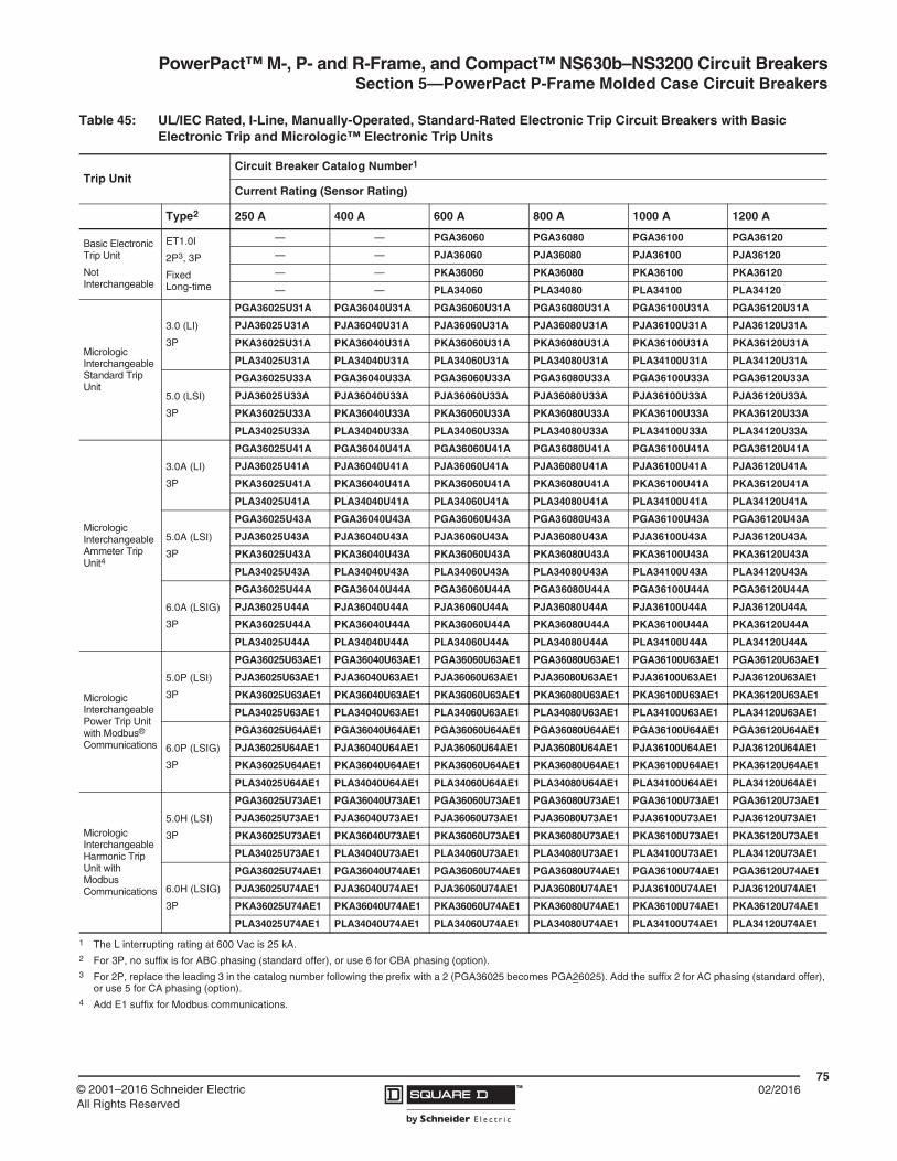
PowerPact™ M-, P- and R-Frame, and Compact™ NS630b–NS3200 Circuit BreakersSection 5—PowerPact P-Frame Molded Case Circuit Breakers
7502/2016™© 2001–2016 Schneider Electric
All Rights Reserved
Table 45: UL/IEC Rated, I-Line, Manually-Operated, Standard-Rated Electronic Trip Circuit Breakers with Basic Electronic Trip and Micrologic™ Electronic Trip Units
Trip UnitCircuit Breaker Catalog Number1
Current Rating (Sensor Rating)
Type2 250 A 400 A 600 A 800 A 1000 A 1200 A
Basic Electronic Trip Unit
Not Interchangeable
ET1.0I
2P3, 3P
Fixed Long-time
— — PGA36060 PGA36080 PGA36100 PGA36120
— — PJA36060 PJA36080 PJA36100 PJA36120
— — PKA36060 PKA36080 PKA36100 PKA36120
— — PLA34060 PLA34080 PLA34100 PLA34120
Micrologic Interchangeable Standard Trip Unit
3.0 (LI)
3P
PGA36025U31A PGA36040U31A PGA36060U31A PGA36080U31A PGA36100U31A PGA36120U31A
PJA36025U31A PJA36040U31A PJA36060U31A PJA36080U31A PJA36100U31A PJA36120U31A
PKA36025U31A PKA36040U31A PKA36060U31A PKA36080U31A PKA36100U31A PKA36120U31A
PLA34025U31A PLA34040U31A PLA34060U31A PLA34080U31A PLA34100U31A PLA34120U31A
5.0 (LSI)
3P
PGA36025U33A PGA36040U33A PGA36060U33A PGA36080U33A PGA36100U33A PGA36120U33A
PJA36025U33A PJA36040U33A PJA36060U33A PJA36080U33A PJA36100U33A PJA36120U33A
PKA36025U33A PKA36040U33A PKA36060U33A PKA36080U33A PKA36100U33A PKA36120U33A
PLA34025U33A PLA34040U33A PLA34060U33A PLA34080U33A PLA34100U33A PLA34120U33A
Micrologic Interchangeable Ammeter Trip Unit4
3.0A (LI)
3P
PGA36025U41A PGA36040U41A PGA36060U41A PGA36080U41A PGA36100U41A PGA36120U41A
PJA36025U41A PJA36040U41A PJA36060U41A PJA36080U41A PJA36100U41A PJA36120U41A
PKA36025U41A PKA36040U41A PKA36060U41A PKA36080U41A PKA36100U41A PKA36120U41A
PLA34025U41A PLA34040U41A PLA34060U41A PLA34080U41A PLA34100U41A PLA34120U41A
5.0A (LSI)
3P
PGA36025U43A PGA36040U43A PGA36060U43A PGA36080U43A PGA36100U43A PGA36120U43A
PJA36025U43A PJA36040U43A PJA36060U43A PJA36080U43A PJA36100U43A PJA36120U43A
PKA36025U43A PKA36040U43A PKA36060U43A PKA36080U43A PKA36100U43A PKA36120U43A
PLA34025U43A PLA34040U43A PLA34060U43A PLA34080U43A PLA34100U43A PLA34120U43A
6.0A (LSIG)
3P
PGA36025U44A PGA36040U44A PGA36060U44A PGA36080U44A PGA36100U44A PGA36120U44A
PJA36025U44A PJA36040U44A PJA36060U44A PJA36080U44A PJA36100U44A PJA36120U44A
PKA36025U44A PKA36040U44A PKA36060U44A PKA36080U44A PKA36100U44A PKA36120U44A
PLA34025U44A PLA34040U44A PLA34060U44A PLA34080U44A PLA34100U44A PLA34120U44A
MicrologicInterchangeable Power Trip Unit with Modbus® Communications
5.0P (LSI)
3P
PGA36025U63AE1 PGA36040U63AE1 PGA36060U63AE1 PGA36080U63AE1 PGA36100U63AE1 PGA36120U63AE1
PJA36025U63AE1 PJA36040U63AE1 PJA36060U63AE1 PJA36080U63AE1 PJA36100U63AE1 PJA36120U63AE1
PKA36025U63AE1 PKA36040U63AE1 PKA36060U63AE1 PKA36080U63AE1 PKA36100U63AE1 PKA36120U63AE1
PLA34025U63AE1 PLA34040U63AE1 PLA34060U63AE1 PLA34080U63AE1 PLA34100U63AE1 PLA34120U63AE1
6.0P (LSIG)
3P
PGA36025U64AE1 PGA36040U64AE1 PGA36060U64AE1 PGA36080U64AE1 PGA36100U64AE1 PGA36120U64AE1
PJA36025U64AE1 PJA36040U64AE1 PJA36060U64AE1 PJA36080U64AE1 PJA36100U64AE1 PJA36120U64AE1
PKA36025U64AE1 PKA36040U64AE1 PKA36060U64AE1 PKA36080U64AE1 PKA36100U64AE1 PKA36120U64AE1
PLA34025U64AE1 PLA34040U64AE1 PLA34060U64AE1 PLA34080U64AE1 PLA34100U64AE1 PLA34120U64AE1
Micrologic Interchangeable Harmonic Trip Unit with Modbus Communications
5.0H (LSI)
3P
PGA36025U73AE1 PGA36040U73AE1 PGA36060U73AE1 PGA36080U73AE1 PGA36100U73AE1 PGA36120U73AE1
PJA36025U73AE1 PJA36040U73AE1 PJA36060U73AE1 PJA36080U73AE1 PJA36100U73AE1 PJA36120U73AE1
PKA36025U73AE1 PKA36040U73AE1 PKA36060U73AE1 PKA36080U73AE1 PKA36100U73AE1 PKA36120U73AE1
PLA34025U73AE1 PLA34040U73AE1 PLA34060U73AE1 PLA34080U73AE1 PLA34100U73AE1 PLA34120U73AE1
6.0H (LSIG)
3P
PGA36025U74AE1 PGA36040U74AE1 PGA36060U74AE1 PGA36080U74AE1 PGA36100U74AE1 PGA36120U74AE1
PJA36025U74AE1 PJA36040U74AE1 PJA36060U74AE1 PJA36080U74AE1 PJA36100U74AE1 PJA36120U74AE1
PKA36025U74AE1 PKA36040U74AE1 PKA36060U74AE1 PKA36080U74AE1 PKA36100U74AE1 PKA36120U74AE1
PLA34025U74AE1 PLA34040U74AE1 PLA34060U74AE1 PLA34080U74AE1 PLA34100U74AE1 PLA34120U74AE1
1 The L interrupting rating at 600 Vac is 25 kA.2 For 3P, no suffix is for ABC phasing (standard offer), or use 6 for CBA phasing (option).3 For 2P, replace the leading 3 in the catalog number following the prefix with a 2 (PGA36025 becomes PGA26025). Add the suffix 2 for AC phasing (standard offer),
or use 5 for CA phasing (option).4 Add E1 suffix for Modbus communications.

PowerPact™ M-, P- and R-Frame, and Compact™ NS630b–NS3200 Circuit Breakers Section 5—PowerPact P-Frame Molded Case Circuit Breakers
7602/2016 ™ © 2001–2016 Schneider Electric
All Rights Reserved
Table 46: UL/IEC Rated, I-Line, Manually-Operated, 100%-Rated Electronic Trip Circuit Breakers with Micrologic™ Electronic Trip Units
Trip Unit, Interchangeable
Circuit Breaker1
Current Rating (Sensor Rating)
Type2 250 A 400 A 600 A 800 A
Micrologic Interchangeable Standard Trip Unit
3.0 (LI)
3P
PGA36025CU31A PGA36040CU31A PGA36060CU31A PGA36080CU31A
PJA36025CU31A PJA36040CU31A PJA36060CU31A PJA36080CU31A
PKA36025CU31A PKA36040CU31A PKA36060CU31A PKA36080CU31A
PLA34025CU31A PLA34040CU31A PLA34060CU31A PLA34080CU31A
5.0 (LSI)
3P
PGA36025CU33A PGA36040CU33A PGA36060CU33A PGA36080CU33A
PJA36025CU33A PJA36040CU33A PJA36060CU33A PJA36080CU33A
PKA36025CU33A PKA36040CU33A PKA36060CU33A PKA36080CU33A
PLA34025CU33A PLA34040CU33A PLA34060CU33A PLA34080CU33A
Micrologic Interchangeable Ammeter Trip Unit3
3.0A (LI)
3P
PGA36025CU41A PGA36040CU41A PGA36060CU41A PGA36080CU41A
PJA36025CU41A PJA36040CU41A PJA36060CU41A PJA36080CU41A
PKA36025CU41A PKA36040CU41A PKA36060CU41A PKA36080CU41A
PLA34025CU41A PLA34040CU41A PLA34060CU41A PLA34080CU41A
5.0A (LSI)
3P
PGA36025CU43A PGA36040CU43A PGA36060CU43A PGA36080CU43A
PJA36025CU43A PJA36040CU43A PJA36060CU43A PJA36080CU43A
PKA36025CU43A PKA36040CU43A PKA36060CU43A PKA36080CU43A
PLA34025CU43A PLA34040CU43A PLA34060CU43A PLA34080CU43A
6.0A (LSIG)
3P
PGA36025CU44A PGA36040CU44A PGA36060CU44A PGA36080CU44A
PJA36025CU44A PJA36040CU44A PJA36060CU44A PJA36080CU44A
PKA36025CU44A PKA36040CU44A PKA36060CU44A PKA36080CU44A
PLA34025CU44A PLA34040CU44A PLA34060CU44A PLA34080CU44A
Micrologic Interchangeable Power Trip Unit with Modbus® Communications
5.0P (LSI)
3P
PGA36025CU63AE1 PGA36040CU63AE1 PGA36060CU63AE1 PGA36080CU63AE1
PJA36025CU63AE1 PJA36040CU63AE1 PJA36060CU63AE1 PJA36080CU63AE1
PKA36025CU63AE1 PKA36040CU63AE1 PKA36060CU63AE1 PKA36080CU63AE1
PLA34025CU63AE1 PLA34040CU63AE1 PLA34060CU63AE1 PLA34080CU63AE1
6.0P (LSIG)
3P
PGA36025CU64AE1 PGA36040CU64AE1 PGA36060CU64AE1 PGA36080CU64AE1
PJA36025CU64AE1 PJA36040CU64AE1 PJA36060CU64AE1 PJA36080CU64AE1
PKA36025CU64AE1 PKA36040CU64AE1 PKA36060CU64AE1 PKA36080CU64AE1
PLA34025CU64AE1 PLA34040CU64AE1 PLA34060CU64AE1 PLA34080CU64AE1
Micrologic Interchangeable Harmonic Trip Unit with Modbus Communications
5.0H (LSI)
3P
PGA36025CU73AE1 PGA36040CU73AE1 PGA36060CU73AE1 PGA36080CU73AE1
PJA36025CU73AE1 PJA36040CU73AE1 PJA36060CU73AE1 PJA36080CU73AE1
PKA36025CU73AE1 PKA36040CU73AE1 PKA36060CU73AE1 PKA36080CU73AE1
PLA34025CU73AE1 PLA34040CU73AE1 PLA34060CU73AE1 PLA34080CU73AE1
6.0H (LSIG)
3P
PGA36025CU74AE1 PGA36040CU74AE1 PGA36060CU74AE1 PGA36080CU74AE1
PJA36025CU74AE1 PJA36040CU74AE1 PJA36060CU74AE1 PJA36080CU74AE1
PKA36025CU74AE1 PKA36040CU74AE1 PKA36060CU74AE1 PKA36080CU74AE1
PLA34025CU74AE1 PLA34040CU74AE1 PLA34060CU74AE1 PLA34080CU74AE1
1 The L interrupting rating at 600 Vac is 25 kA.2 No suffix is for ABC phasing (standard offer), or use 6 for CBA phasing (option).3 Add E1 suffix for Modbus communications.
Table 47: P-Frame Termination Options Table 48: P-Frame Interrupting Ratings
F = No Lugs (Includes terminal nut kit on both ends)L = Lugs both endsM = Lugs I/ON end, terminal nut kit O/OFF endP = Lugs O/OFF end, terminal nut kit I/ON endD = DrawoutA = I-Line
VoltageP-Frame Interrupting Rating
G J K L240 Vac 65 kA 100 kA 65 kA 125 kA
480 Vac 35 kA 65 kA 50 kA 100 kA
600 Vac 18 kA 25 kA 50 kA 25 kA
P G L 3 6 0 4 0 U 4 1 A
For factory-installed termination, place termination letter in the third block of the circuit breaker catalog number.
Termination Letter

PowerPact™ M-, P- and R-Frame, and Compact™ NS630b–NS3200 Circuit BreakersSection 5—PowerPact P-Frame Molded Case Circuit Breakers
7702/2016™© 2001–2016 Schneider Electric
All Rights Reserved
Continuous Current Rating
All circuit breakers marked as 100% rated can be continuously loaded to 100% of their rating.
Because of additional heat generated when applying circuit breakers at 100% of continuous current rating, the use of specially-designed enclosures and 90°C (194°F) wire is required. The 90°C (194°F) wire must be sized according to the ampacity of the 75°C (167°F) wire column in the NEC. Minimum enclosure size and ventilation specifications are indicated on the circuit breaker and in it’s instruction bulletin and in Table 5 on page 11.
Circuit breakers with 100% rating can also be used in applications requiring only 80% continuous loading.
Interrupting Ratings
Table 49: Interrupting Ratings
MountingCircuit Breaker
Ampere Rating (A) Interrupting Ratings
Basic Electronic Trip Units
Micrologic™ Trip Units
UL/CSA/NMXIEC 60947-2
240 Vac 380/415 Vac
240 Vac
480 Vac
600 Vac
Icu Ics Icu Ics
Individually-Mounted
PG
600, 800, 1000, 1200
250, 400, 600, 800, 1000, 1200
65 kA 35 kA 18 kA 50 kA 25 kA 35 kA 20 kA
PJ 100 kA 65 kA 25 kA 65 kA 35 kA 50 kA 25 kA
PK 65 kA 50 kA 50 kA 50 kA 25 kA 50 kA 25 kA
PL 125 kA 100 kA 25 kA1
1 Non-standard AIR.
125 kA 65 kA 85 kA 45kA
I-Line™
PG
600, 800, 1000, 1200
250, 400, 600, 800, 1000, 1200
65 kA 35 kA 18 kA 50 kA 25 kA 35 kA 20 kA
PJ 100 kA 65 kA 25 kA 65 kA 35 kA 50 kA 25 kA
PK 65 kA 50 kA 50 kA 50 kA 25 kA 50 kA 25 kA
PL 125 kA 100 kA 25 kA1 125 kA 65 kA 85 kA 45 kA

PowerPact™ M-, P- and R-Frame, and Compact™ NS630b–NS3200 Circuit Breakers Section 5—PowerPact P-Frame Molded Case Circuit Breakers
7802/2016 ™ © 2001–2016 Schneider Electric
All Rights Reserved
Automatic Molded Case Switches1
Automatic molded case switches are available in individually-mounted and I-Line constructions from 600–1200 A. Automatic switches are similar in construction to electronic trip circuit breakers except that long-time tripping is not present. The switches open instantaneously at a non-adjustable magnetic trip point calibrated to protect only the molded case switch itself. They must be used in conjunction with a circuit breaker or fuse of equivalent rating.
1 Catalog numbers for automatic switches are designated by “000” in positions 7–9 (ampere rating) and S60, S80, S10, or S12 in positions 11–14 (trip system). See Table 10.
Table 50: Automatic Switch Information
Circuit Breaker
AmpereRating
Voltage Rating
Catalog Number
Withstand Rating Trip Point(±10%)240 Vac 480 Vac 600 Vac
PJ
2P1, 3P
1 For 2P, replace the leading 3 in the catalog number following the prefix with a 2 (PJL36000S60 becomes PJL26000S60). Add the suffix 2 for AC phasing (standard offer), or use 5 for CA phasing (option).
600 600 Vac PJL36000S60 100 kA 65 kA 25 kA 10 kA
800 600 Vac PJL36000S80 100 kA 65 kA 25 kA 10 kA
1000 600 Vac PJL36000S10 100 kA 65 kA 25 kA 10 kA
1200 600 Vac PJL36000S12 100 kA 65 kA 25 kA 10 kA
PK
2P, 3P, 4P2
2 For 4P, replace the leading 3 in the catalog number following the prefix with a 4 (PKL36000S60 becomes PKL46000S60).
600 600 Vac PKL36000S60 65 kA 50 kA 50 kA 24 kA
800 600 Vac PKL36000S80 65 kA 50 kA 50 kA 24 kA
1000 600 Vac PKL36000S10 65 kA 50 kA 50 kA 24 kA
1200 600 Vac PKL36000S12 65 kA 50 kA 50 kA 24 kA
PL
2P, 3P
600 480 Vac PLL34000S60 125 kA 100 kA — 10 kA
800 480 Vac PLL34000S80 125 kA 100 kA — 10 kA
1000 480 Vac PLL34000S10 125 kA 100 kA — 10 kA
1200 480 Vac PLL34000S12 125 kA 100 kA — 10 kA

PowerPact™ M-, P- and R-Frame, and Compact™ NS630b–NS3200 Circuit BreakersSection 5—PowerPact P-Frame Molded Case Circuit Breakers
7902/2016™© 2001–2016 Schneider Electric
All Rights Reserved
Motor Circuit Protectors2
Motor circuit protectors are similar in construction to thermal-magnetic circuit breakers, but have only instantaneous trip functions provided by the ET1.0M trip unit. These motor circuit protectors comply with NEC requirements for providing short-circuit protection when installed as part of a listed combination controller having motor overload protection. Interrupting ratings are determined by testing the motor circuit protector in combination with a contactor and overload relay.
Motor circuit protectors are available in PJ and PL individually-mounted and I-Line™ construction. According to the NEC, the instantaneous trip of the motor circuit protector may be set to a maximum of 8 to 17 times motor Full Load Amps (FLA), but a setting as close as possible to inrush current (without nuisance tripping) results in the best protection. The instantaneous trip pickup level is adjustable within the ranges shown below.
NOTE: Continuous currents larger than the ampere rating can damage the motor circuit protector.
Select motor circuit protectors as follows:
1. Determine motor horsepower (hp) rating from the motor nameplate. The selection table is suitable for motors with locked-rotor indicating code letters per NEC Table 430-7 (b) as follows:
For other motors contact the field office.
2. Select a motor circuit protector with an ampere rating recommended for the hp and voltage involved.
3. Select an adjustable trip setting of at least 800% but not to exceed 1300% (1700% for high-efficiency motors) of the motor full load amperes (FLA).
4. The NEC 1300% maximum setting (1700% for high-efficiency motors) may be inadequate for motor circuit protectors to withstand current surges typical of the magnetization current of auto-transformer type reduced voltage starters or open transition wye-delta starters during transfer from “start” to “run,” constant hp multi-speed motors and motors labeled “high efficiency”.
5. Part-winding motors, per NEC 430-3, should have two motor circuit protectors selected from the above at not more than one-half the allowable trip setting for the horsepower rating. The two circuit protectors should operate simultaneously as a disconnecting means per NEC 430-103.
2 Catalog numbers for motor circuit protectors are designated by M68, M69, or M70 in positions 11–14 (trip system). See Table 10.
Table 51: Motor Circuit Protector Trip Range
Ampere Rating
Adjustable Trip Range
Catalog Number
J-Interrupting—600 Vac L-Interrupting—480 Vac
600 A 1200–10,000 A PJL36060M68 PLL34060M68
800 A 1200–10,000 A PJL36080M68 PLL34080M68
1000 A 1500–10,000 A PJL36100M69 PLL34100M69
1200 A 1800–10,000 A PJL36120M70 PLL34120M70
Horsepower Motor Code Letters
30–150 A–G
150 or More A–F
PowerPact™ M-, P- and R-Frame, and Compact™ NS630b–NS3200 Circuit Breakers Section 5—PowerPact P-Frame Molded Case Circuit Breakers
8002/2016 ™ © 2001–2016 Schneider Electric
All Rights Reserved
Electrically-Operated Circuit Breakers
Electrically-operated P-frame circuit breakers are available in I-Line and unit-mount construction up to 1200 A and are denoted in the catalog number by an “M_” suffix. These come equipped with a two-step stored energy mechanism and come standard with a motor assembly. These are available factory-installed only.
Motor assemblies provide on and off control from remote locations. The assemblies contain a spring-charging motor (MCH), a shunt trip (MX) and a shunt close (XF) and are available in standard or communicating versions. An SDE overcurrent trip switch is also included for trip indication. When remote indication of the circuit breaker status is required, use of a circuit breaker with an OF auxiliary switch for on-off indication. See Table 74 on page 105 for details.
Termination Information
Unit-mount circuit breakers and switches have mechanical lugs standard on both ends. I-Line circuit breakers have lugs standard on the O/OFF end. These lugs accept aluminum or copper wire. Manually-operated P-frame circuit breakers are also available in drawout construction. See Table 91 on page 114 for more lug options.
Control Wiring
Control wiring for unit-mount and I-Line construction is connected to terminals located under the circuit breaker accessory cover. Control wiring for drawout construction is connected to terminals located on the cradle.
Table 52: Motors Assembly Voltage Ratings (Vn)
Voltage Type Voltage Ratings (Vn)
Vac 50/60 Hz 48, 100–130, 220–240, 380–415
Vdc 24–30, 48–60, 110–130, 200–250
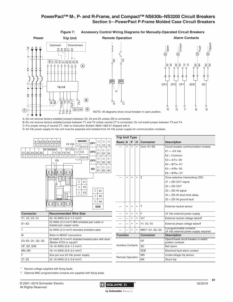
PowerPact™ M-, P- and R-Frame, and Compact™ NS630b–NS3200 Circuit BreakersSection 5—PowerPact P-Frame Molded Case Circuit Breakers
8102/2016™© 2001–2016 Schneider Electric
All Rights Reserved
Figure 7: Accessory Control Wiring Diagrams for Manually-Operated Circuit Breakers
Trip Unit Type
Basic A P H Connector Description— • • • Com: E1-E6 Circuit breaker communication module
E1 = +24 Vdc
E2 = Common
E3 = A/Tx- D0
E4 = B/Tx+ D1
E5 = A/Rx- D0
E6 = B/Rx+ D1
— • • • Z Zone-selective interlocking (ZSI)
Z1 = ZSI OUT signal
Z2 = ZSI OUT
Z3 = ZSI IN signal
Z4 = ZSI IN short-time delay
Z5 = ZSI IN ground fault
— • • • T External neutral sensor
Connector Recommended Wire Size — • • • F 24 Vdc external power supply
V1, V2, V3, Vn 22–16 AWG (0.3–1.5 mm2) — — • • Vn1 External neutral voltage takeoff
E1–E222 AWG (0.3 mm2) MIN shielded pair cable or twisted pair copper wires — — • • V1, V2, V3 External phase voltage takeoff
T 22 AWG (0.3 mm2) stranded shielded cable — — • • M6C2: Q1, Q2, Q3 6 programmable contacts24 Vdc external power supply required
M Refer to MDGF instructions Function Connector Description
E3–E6, Q1, Q2, Q322 AWG (0.3 mm2) shielded twisted pairs with drain (Belden 8723 or equal)3
Auxiliary Contacts
OFOpen/Closed circuit breaker or switch position contacts
OF, SD, SDE 18–16 AWG (0.8–1.5 mm2) SD Bell alarm
MN, MX 18–14 AWG (0.8–2.5 mm2) SDE Electrical fault alarm contact
F Size per aux 24 Vdc power supplyRemote Operation
MN Undervoltage trip device
Z1–Z5 22–18 AWG (0.3–0.8 mm2) MX Shunt trip
1 Neutral voltage supplied with flying leads.2 Optional M6C programmable contacts are supplied with flying leads.
22 2421
OF2
Clo
sed
OF3
32 3431
Ope
n
12 1411
OF1
92 9491
SD
Trip
ped
82 8481
SDE
Fau
lt
T4
T3
T2T1
Z3
Z4
T3
T2
Trip Unit
Z4
Z3
Z2
Z1
Z5
Z2
Z1N CBA
Z5
VN
V1
V2
V3
M2
M1
F2+
Upstream Downstream
24 V
T1/
M3
T4/
F1-
or
D2
D1
MN MX
C2
C1
Power Trip Unit Remote Operation Alarm Contacts
NOTE: All diagrams show circuit breaker in open position.
A
DC
B
A–Do not remove factory-installed jumpers between Z3, Z4 and Z5 unless ZSI is connected. B–Do not remove factory-installed jumper between T1 and T2 unless neutral CT is connected. Do not install jumper between T3 and T4.C–For proper wiring of neutral CT, refer to Instruction Bulletin 48041-082-01 shipped with it.D–24 Vdc power supply for trip unit must be separate and isolated from 24 Vdc power supply for communication modules.
D1/C1
C3
MN/MXOF1
OF2
OF3
SD
82
81
SDE
84
11
21
31
91
VN
12
22
32
92
14
24
34
94
E1 E6
Z2 T2M2 F1 F2
Z4Z3Z1 Z5M1
T1 T4T3
E2 E3 E4 E5
M3
D2/C2
- +24 Vdc
V2
V1
V3

PowerPact™ M-, P- and R-Frame, and Compact™ NS630b–NS3200 Circuit Breakers Section 5—PowerPact P-Frame Molded Case Circuit Breakers
8202/2016 ™ © 2001–2016 Schneider Electric
All Rights Reserved
Figure 8: Accessory Control Wiring Diagrams for Electrically-operated Circuit Breakers
Trip Unit Type
Basic A P H Connector Description
— • • • Com: E1-E6 Circuit breaker communication module
E1 = +24 Vdc
E2 = Common
E3 = A/Tx- D0
E4 = B/Tx+ D1
E5 = A/Rx- D0
E6 = B/Rx+ D1
— • • • Z Zone-selective interlocking (ZSI)
Z1 = ZSI OUT signal
Z2 = ZSI OUT
Z3 = ZSI IN signal
Z4 = ZSI IN short-time delay
Z5 = ZSI IN ground fault
— • • • T External neutral sensor
— • • • F 24 Vdc external power supply
— — • • Vn1 External voltage takeoff
Connector Recommended Wire Size — — • • V1, V2, V31 External phase voltage takeoff
E1–E2 22 AWG (0.3 mm2) MIN shielded pair cable or twisted pair copper wires
— — • • M6C1: Q1, Q2, Q3
6 programmable contacts24 Vdc external power supply required
V1, V2, V3, Vn 22–16 AWG (0.3–1.5 mm2) Function Connector Description
T 22 AWG (0.3 mm2) stranded shielded cableAuxiliary Contacts
OF Open/Closed circuit breaker or switch position contacts
E3–E6, Q1, Q2, Q3 22 AWG (0.3 mm2) shielded twisted pairs with drain (Belden 8723 or equal)3 SDE Electrical fault alarm contact
M Refer to MDGF instructionsRemote Operation
MN Undervoltage trip device
OF, SD, SDE 18–16 AWG (0.8–1.5 mm2) MX Shunt trip
MN, MX 18–14 AWG (0.8–2.5 mm2)
Motor Mech Module
A4 Electrical opening
F Size per aux 24 Vdc power supply A2 Electrical closing
Z1–Z5 22–18 AWG (0.3–0.8 mm2) B4, A1 Power supply for control devices and gear motor
1 Optional M6C and external voltage takeoff are supplied with flying leads.
T4
T3
T2T1
Z3
Z4
T3
T2
Trip Unit
Z4
Z3
Z2
Z1
Z5
Z2
Z1N CBA
Z5
VN
V1
V2
V3
M2
M1
F2+
Upstream Downstream
24 V
T1/
M3
T4/
F1-
or
D2
D1
MN MX
C2
C1
Open
A4
Close
A2
B4
Motor Mechanism Module
A1
Power Trip Unit Remote Operation Alarm Contacts
22 2421
OF2
Clo
sed
OF3
32 3431
Ope
n
12 1411
OF1
82 8481
SDE
Fau
lt
NOTE: All diagrams show circuit breaker in open position.
A
DC
B
A–Do not remove factory-installed jumpers between Z3, Z4 and Z5 unless ZSI is connected. B–Do not remove factory-installed jumper between T1 and T2 unless neutral CT is connected. Do not install jumper between T3 and T4.C–For proper wiring of neutral CT, refer to Instruction Bulletin 48041-082-01 shipped with it.D–24 Vdc power supply for trip unit must be separate and isolated from 24 Vdc power supply for communication modules.E–Motor mechanism includes opening and closing coils.
E
D1/C1
D2/C2
MN/MX
VN, V1, V2, V3
OF1OF2OF3SDE
81
32
84 14
A1A2A4B4
112131
22 1282
34 24
E1 E6
Z2 T2M2 F1 F2
Z4Z3Z1 Z5M1
T1 T4T3
E2 E3 E4 E5
M3
24 Vdc- +

PowerPact™ M-, P- and R-Frame, and Compact™ NS630b–NS3200 Circuit BreakersSection 6—PowerPact R-Frame Circuit Breakers
8302/2016™© 2001–2016 Schneider Electric
All Rights Reserved
Section 6—PowerPact R-Frame Circuit Breakers
Performance
Providing unparalleled performance and control, the R-frame circuit breakers features the exclusive Micrologic electronic trip units, which allow for a range of sophisticated applications for metering and monitoring. In addition, trip units can be interchanged in the field to allow for maximum flexibility.
The compact size and smaller footprint of the R-frame circuit breaker permits higher density installations using I-Line panelboards and switchboards. These circuit breakers are available in 100% rated construction up to 3000 A to meet a broad range of commercial and industrial application needs.
• Both standard and 100% rated construction circuit breakers are available in 3000 A with a sensor size range of 600–3000 A.
• Interrupting ratings (AIR):
• The K interrupting rating is recommended for applications having high inrush and/or non-linear loads such as large motors, transformers, motors with soft starts, etc.
• Compact circuit breaker size allows for smaller footprint installations using I-Line panelboards and switchboards. Fifteen-inch width provides increased density installation.
• Most field-installable accessories are common to all frame sizes for easier stocking and installation
• Selection of four interchangeable Micrologic trip units available, with Powerlogic power metering and monitoring capabilities available in advanced trip units.
• Compatible with Powerlogic systems and high amperage power circuit breakers.
• Built-in Modbus protocol provides an open communications platform and eliminates the need to purchase additional, proprietary network solutions.
• Connection options include bus, cable or I-Line for installation flexibility.
R-Frame Unit-Mount
R-Frame I-Line
Voltage G J K L
240 Vac 65 kA 100 kA 65 kA 125 kA
480 Vac 35 kA 65 kA 65 kA 100 kA
600 Vac 18 kA 25 kA 65 kA 50 kA

PowerPact™ M-, P- and R-Frame, and Compact™ NS630b–NS3200 Circuit Breakers Section 6—PowerPact R-Frame Circuit Breakers
8402/2016 ™ © 2001–2016 Schneider Electric
All Rights Reserved
Catalog Numbers
Table 53: UL/IEC Rated, Unit-Mount, Manually-Operated, Standard-Rated Electronic Trip Circuit Breakers with Basic Electronic Trip and Micrologic™ Electronic Trip Units—600A to 1200A
Trip UnitType
Circuit Breaker Catalog Number
Current Rating (Sensor Rating)
600 A 800 A 1000 A 1200 A
Basic Electronic Trip Unit Not interchangeable
ET1.0I
2P1, 3P
Fixed Long-time
1 For 2P, replace the leading 3 in the catalog number following the prefix with a 2 (RGF36060 becomes RGF26060.)
— — — RGF36120
— — — RJF36120
— — — RKF36120
— — — RLF36120
Micrologic Interchangeable Standard Trip Unit
3.0
(LI)
3P, 4P2
2 For 4P, replace the leading 3 in the catalog number following the prefix with a 4 (RPF36060U31A becomes RGF46060U31A).
RGF36060U31A RGF36080U31A RGF36100U31A RGF36120U31A
RJF36060U31A RJF36080U31A RJF36100U31A RJF36120U31A
RKF36060U31A RKF36080U31A RKF36100U31A RKF36120U31A
RLF36060U31A RLF36080U31A RLF36100U31A RLF36120U31A
5.0
(LSI)
3P, 4P2
RGF36060U33A RGF36080U33A RGF36100U33A RGF36120U33A
RJF36060U33A RJF36080U33A RJF36100U33A RJF36120U33A
RKF36060U33A RKF36080U33A RKF36100U33A RKF36120U33A
RLF36060U33A RLF36080U33A RLF36100U33A RLF36120U33A
Micrologic Interchangeable Ammeter Trip Unit3
3 Add E1 suffix for Modbus communications.
3.0A
(LI)
3P, 4P2
RGF36060U41A RGF36080U41A RGF36100U41A RGF36120U41A
RJF36060U41A RJF36080U41A RJF36100U41A RJF36120U41A
RKF36060U41A RKF36080U41A RKF36100U41A RKF36120U41A
RLF36060U41A RLF36080U41A RLF36100U41A RLF36120U41A
5.0A
(LSI)
3P, 4P2
RGF36060U43A RGF36080U43A RGF36100U43A RGF36120U43A
RJF36060U43A RJF36080U43A RJF36100U43A RJF36120U43A
RKF36060U43A RKF36080U43A RKF36100U43A RKF36120U43A
RLF36060U43A RLF36080U43A RLF36100U43A RLF36120U43A
6.0A (LSIG)
3P, 4P2
RGF36060U44A RGF36080U44A RGF36100U44A RGF36120U44A
RJF36060U44A RJF36080U44A RJF36100U44A RJF36120U44A
RKF36060U44A RKF36080U44A RKF36100U44A RKF36120U44A
RLF36060U44A RLF36080U44A RLF36100U44A RLF36120U44A
Micrologic Interchangeable Power Trip Unit with Modbus® Communications
5.0P
(LSI)
3P, 4P2
RGF36060U63AE1 RGF36080U63AE1 RGF36100U63AE1 RGF36120U63AE1
RJF36060U63AE1 RJF36080U63AE1 RJF36100U63AE1 RJF36120U63AE1
RKF36060U63AE1 RKF36080U63AE1 RKF36100U63AE1 RKF36120U63AE1
RLF36060U63AE1 RLF36080U63AE1 RLF36100U63AE1 RLF36120U63AE1
6.0P (LSIG)
3P, 4P2
RGF36060U64AE1 RGF36080U64AE1 RGF36100U64AE1 RGF36120U64AE1
RJF36060U64AE1 RJF36080U64AE1 RJF36100U64AE1 RJF36120U64AE1
RKF36060U64AE1 RKF36080U64AE1 RKF36100U64AE1 RKF36120U64AE1
RLF36060U64AE1 RLF36080U64AE1 RLF36100U64AE1 RLF36120U64AE1
Micrologic Interchangeable Harmonic Trip Unit with Modbus Communications
5.0H
(LSI)
3P, 4P2
RGF36060U73AE1 RGF36080U73AE1 RGF36100U73AE1 RGF36120U73AE1
RJF36060U73AE1 RJF36080U73AE1 RJF36100U73AE1 RJF36120U73AE1
RKF36060U73AE1 RKF36080U73AE1 RKF36100U73AE1 RKF36120U73AE1
RLF36060U73AE1 RLF36080U73AE1 RLF36100U73AE1 RLF36120U73AE1
6.0H (LSIG)
3P, 4P2
RGF36060U74AE1 RGF36080U74AE1 RGF36100U74AE1 RGF36120U74AE1
RJF36060U74AE1 RJF36080U74AE1 RJF36100U74AE1 RJF36120U74AE1
RKF36060U74AE1 RKF36080U74AE1 RKF36100U74AE1 RKF36120U74AE1
RLF36060U74AE1 RLF36080U74AE1 RLF36100U74AE1 RLF36120U74AE1
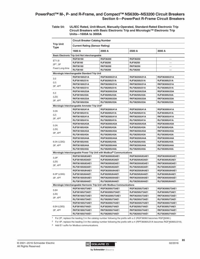
PowerPact™ M-, P- and R-Frame, and Compact™ NS630b–NS3200 Circuit BreakersSection 6—PowerPact R-Frame Circuit Breakers
8502/2016™© 2001–2016 Schneider Electric
All Rights Reserved
Table 54: UL/IEC Rated, Unit-Mount, Manually-Operated, Standard-Rated Electronic Trip Circuit Breakers with Basic Electronic Trip and Micrologic™ Electronic Trip Units—1600A to 3000A
Trip UnitType
Circuit Breaker Catalog Number
Current Rating (Sensor Rating)
1600 A 2000 A 2500 A 3000 A
Basic Electronic Trip Unit Not interchangeable
ET1.0I
2P1, 3P
Fixed Long-time
RGF36160 RGF36200 RGF36250 —
RJF36160 RJF36200 RJF36250 —
RKF36160 RKF36200 RKF36250 —
RLF36160 RLF36200 RLF36250 —
Micrologic Interchangeable Standard Trip Unit
3.0
(LI)
3P, 4P2
RGF36160U31A RGF36200U31A RGF36250U31A RGF36300U31A
RJF36160U31A RJF36200U31A RJF36250U31A RJF36300U31A
RKF36160U31A RKF36200U31A RKF36250U31A RKF36300U31A
RLF36160U31A RLF36200U31A RLF36250U31A RLF36300U31A
5.0
(LSI)
3P, 4P2
RGF36160U33A RGF36200U33A RGF36250U33A RGF36300U33A
RJF36160U33A RJF36200U33A RJF36250U33A RJF36300U33A
RKF36160U33A RKF36200U33A RKF36250U33A RKF36300U33A
RLF36160U33A RLF36200U33A RLF36250U33A RLF36300U33A
Micrologic Interchangeable Ammeter Trip Unit3
3.0A
(LI)
3P, 4P2
RGF36160U41A RGF36200U41A RGF36250U41A RGF36300U41A
RJF36160U41A RJF36200U41A RJF36250U41A RJF36300U41A
RKF36160U41A RKF36200U41A RKF36250U41A RKF36300U41A
RLF36160U41A RLF36200U41A RLF36250U41A RLF36300U41A
5.0A
(LSI)
3P, 4P2
RGF36160U43A RGF36200U43A RGF36250U43A RGF36300U43A
RJF36160U43A RJF36200U43A RJF36250U43A RJF36300U43A
RKF36160U43A RKF36200U43A RKF36250U43A RKF36300U43A
RLF36160U43A RLF36200U43A RLF36250U43A RLF36300U43A
6.0A (LSIG)
3P, 4P2
RGF36160U44A RGF36200U44A RGF36250U44A RGF36300U44A
RJF36160U44A RJF36200U44A RJF36250U44A RJF36300U44A
RKF36160U44A RKF36200U44A RKF36250U44A RKF36300U44A
RLF36160U44A RLF36200U44A RLF36250U44A RLF36300U44A
Micrologic Interchangeable Power Trip Unit with Modbus® Communications
5.0P
(LSI)
3P, 4P2
RGF36160U63AE1 RGF36200U63AE1 RGF36250U63AE1 RGF36300U63AE1
RJF36160U63AE1 RJF36200U63AE1 RJF36250U63AE1 RJF36300U63AE1
RKF36160U63AE1 RKF36200U63AE1 RKF36250U63AE1 RKF36300U63AE1
RLF36160U63AE1 RLF36200U63AE1 RLF36250U63AE1 RLF36300U63AE1
6.0P (LSIG)
3P, 4P2
RGF36160U64AE1 RGF36200U64AE1 RGF36250U64AE1 RGF36300U64AE1
RJF36160U64AE1 RJF36200U64AE1 RJF36250U64AE1 RJF36300U64AE1
RKF36160U64AE1 RKF36200U64AE1 RKF36250U64AE1 RKF36300U64AE1
RLF36160U64AE1 RLF36200U64AE1 RLF36250U64AE1 RLF36200U64AE1
Micrologic Interchangeable Harmonic Trip Unit with Modbus Communications
5.0H
(LSI)
3P, 4P2
RGF36160U73AE1 RGF36200U73AE1 RGF36250U73AE1 RGF36300U73AE1
RJF36160U73AE1 RJF363200U73AE1 RJF36250U73AE1 RJF36300U73AE1
RKF36160U73AE1 RKF363200U73AE1 RKF36250U73AE1 RKF36300U73AE1
RLF36160U73AE1 RLF36200U73AE1 RLF36250U73AE1 RLF36300U73AE1
6.0H (LSIG)
3P, 4P2
RGF36160U74AE1 RGF36200U74AE1 RGF36250U74AE1 RGF36300U74AE1
RJF36160U74AE1 RJF36200U74AE1 RJF36250U74AE1 RJF36300U74AE1
RKF36160U74AE1 RKF36200U74AE1 RKF36250U74AE1 RKF36300U74AE1
RLF36160U74AE1 RLF36200U74AE1 RLF36250U74AE1 RLF36300U74AE1
1 For 2P, replace the leading 3 in the catalog number following the prefix with a 2 (RGF36060 becomes RGF26060.)2 For 4P, replace the leading 3 in the catalog number following the prefix with a 4 (RPF36060U31A becomes RGF46060U31A).3 Add E1 suffix for Modbus communications.

PowerPact™ M-, P- and R-Frame, and Compact™ NS630b–NS3200 Circuit Breakers Section 6—PowerPact R-Frame Circuit Breakers
8602/2016 ™ © 2001–2016 Schneider Electric
All Rights Reserved
Table 55: UL/IEC Rated, Unit-Mount, Manually-Operated, 100%-Rated Electronic Trip Circuit Breakers with Micrologic™ Electronic Trip Units—600 A to 1200 A
Trip UnitType
Circuit Breaker Catalog Number1
1 For 4P, replace the leading 3 in the catalog number following the prefix with a 4 (RPF36060CU31A becomes RGF46060CU31A).
Current Rating (Sensor Rating)
600 A 800 A 1000 A 1200 A
Micrologic Standard Trip Unit Interchangeable, 3P, 4P
3.0
(LI)
RGF36060CU31A RGF36080CU31A RGF36100CU31A RGF36120CU31A
RJF36060CU31A RJF36080CU31A RJF36100CU31A RJF36120CU31A
RKF36060CU31A RKF36080CU31A RKF36100CU31A RKF36120CU31A
RLF36060CU31A RLF36080CU31A RLF36100CU31A RLF36120CU31A
5.0
(LSI)
RGF36060CU33A RGF36080CU33A RGF36100CU33A RGF36120CU33A
RJF36060CU33A RJF36080CU33A RJF36100CU33A RJF36120CU33A
RKF36060CU33A RKF36080CU33A RKF36100CU33A RKF36120CU33A
RLF36060CU33A RLF36080CU33A RLF36100CU33A RLF36120CU33A
Micrologic Ammeter Trip Unit2 Interchangeable, 3P, 4P
2 Add E1 suffix for Modbus communications.
3.0A
(LI)
RGF36060CU41A RGF36080CU41A RGF36100CU41A RGF36120CU41A
RJF36060CU41A RJF36080CU41A RJF36100CU41A RJF36120CU41A
RKF36060CU41A RKF36080CU41A RKF36100CU41A RKF36120CU41A
RLF36060CU41A RLF36080CU41A RLF36100CU41A RLF36120CU41A
5.0A
(LSI)
RGF36060CU43A RGF36080CU43A RGF36100CU43A RGF36120CU43A
RJF36060CU43A RJF36080CU43A RJF36100CU43A RJF36120CU43A
RKF36060CU43A RKF36080CU43A RKF36100CU43A RKF36120CU43A
RLF36060CU43A RLF36080CU43A RLF36100CU43A RLF36120CU43A
6.0A (LSIG)
RGF36060CU44A RGF36080CU44A RGF36100CU44A RGF36120CU44A
RJF36060CU44A RJF36080CU44A RJF36100CU44A RJF36120CU44A
RKF36060CU44A RKF36080CU44A RKF36100CU44A RKF36120CU44A
RLF36060CU44A RLF36080CU44A RLF36100CU44A RLF36120CU44A
Micrologic Power Trip Unit with Modbus® Communications Interchangeable, 3P, 4P
5.0P
(LSI)
RGF36060CU63AE1 RGF36080CU63AE1 RGF36100CU63AE1 RGF36120CU63AE1
RJF36060CU63AE1 RJF36080CU63AE1 RJF36100CU63AE1 RJF36120CU63AE1
RKF36060CU63AE1 RKF36080CU63AE1 RKF36100CU63AE1 RKF36120CU63AE1
RLF36060CU63AE1 RLF36080CU63AE1 RLF36100CU63AE1 RLF36120CU63AE1
6.0P (LSIG)
RGF36060CU64AE1 RGF36080CU64AE1 RGF36100CU64AE1 RGF36120CU64AE1
RJF36060CU64AE1 RJF36080CU64AE1 RJF36100CU64AE1 RJF36120CU64AE1
RKF36060CU64AE1 RKF36080CU64AE1 RKF36100CU64AE1 RKF36120CU64AE1
RLF36060CU64AE1 RLF36080CU64AE1 RLF36100CU64AE1 RLF36120CU64AE1
Micrologic Harmonic Trip Unit with Modbus Communications Interchangeable, 3P, 4P
5.0H
(LSI)
RGF36060CU73AE1 RGF36080CU73AE1 RGF36100CU73AE1 RGF36120CU73AE1
RJF36060CU73AE1 RJF36080CU73AE1 RJF36100CU73AE1 RJF36120CU73AE1
RKF36060CU73AE1 RKF36080CU73AE1 RKF36100CU73AE1 RKF36120CU73AE1
RLF36060CU73AE1 RLF36080CU73AE1 RLF36100CU73AE1 RLF36120CU73AE1
6.0H (LSIG)
RGF36060CU74AE1 RGF36080CU74AE1 RGF36100CU74AE1 RGF36120CU74AE1
RJF36060CU74AE1 RJF36080CU74AE1 RJF36100CU74AE1 RJF36120CU74AE1
RKF36060CU74AE1 RKF36080CU74AE1 RKF36100CU74AE1 RKF36120CU74AE1
RLF36060CU74AE1 RLF36080CU74AE1 RLF36100CU74AE1 RLF36120CU74AE1

PowerPact™ M-, P- and R-Frame, and Compact™ NS630b–NS3200 Circuit BreakersSection 6—PowerPact R-Frame Circuit Breakers
8702/2016™© 2001–2016 Schneider Electric
All Rights Reserved
Table 56: UL/IEC Rated, Unit-Mount, Manually-Operated, 100%-Rated Electronic Trip Circuit Breakers with Micrologic™ Electronic Trip Units—1600 A to 3000 A
Trip UnitType
Circuit Breaker Catalog Number1
Current Rating (Sensor Rating)
1600 A 2000 A 2500 A 3000 A
Micrologic Standard Trip Unit Interchangeable, 3P, 4P
3.0
(LI)
RGF36160CU31A RGF36200CU31A RGF36250CU31A RGF36300CU31A
RJF36160CU31A RJF36200CU31A RJF36250CU31A RJF36300CU31A
RKF36160CU31A RKF36200CU31A RKF36250CU31A RKF36300CU31A
RLF36160CU31A RLF36200CU31A RLF36250CU31A RLF36300CU31A
5.0
(LSI)
RGF36160CU33A RGF36200CU33A RGF36250CU33A RGF36300CU33A
RJF36160CU33A RJF36200CU33A RJF36250CU33A RJF36300CU33A
RKF36160CU33A RKF36200CU33A RKF36250CU33A RKF36300CU33A
RLF36160CU33A RLF36200CU33A RLF36250CU33A RLF36300CU33A
Micrologic Ammeter Trip Unit2 Interchangeable, 3P, 4P
3.0A
(LI)
RGF36160CU41A RGF36200CU41A RGF36250CU41A RGF36300CU41A
RJF36160CU41A RJF36200CU41A RJF36250CU41A RJF36300CU41A
RKF36160CU41A RKF36200CU41A RKF36250CU41A RKF36300CU41A
RLF36160CU41A RLF36200CU41A RLF36250CU41A RLF36300CU41A
5.0A
(LSI)
RGF36160CU43A RGF36200CU43A RGF36250CU43A RGF36300CU43A
RJF36160CU43A RJF36200CU43A RJF36250CU43A RJF36300CU43A
RKF36160CU43A RKF36200CU43A RKF36250CU43A RKF36300CU43A
RLF36160CU43A RLF36200CU43A RLF36250CU43A RLF36300CU43A
6.0A (LSIG)
RGF36160CU44A RGF36200CU44A RGF36250CU44A RGF36300CU44A
RJF36160CU44A RJF36200CU44A RJF36250CU44A RJF36300CU44A
RKF36160CU44A RKF36200CU44A RKF36250CU44A RKF36300CU44A
RLF36160CU44A RLF36200CU44A RLF36250CU44A RLF36300CU44A
Micrologic Power Trip Unit with Modbus® Communications Interchangeable, 3P, 4P
5.0P
(LSI)
RGF36160CU63AE1 RGF36200CU63AE1 RGF36250CU63AE1 RGF36300CU63AE1
RJF36160CU63AE1 RJF36200CU63AE1 RJF36250CU63AE1 RJF36300CU63AE1
RKF36160CU63AE1 RKF36200CU63AE1 RKF36250CU63AE1 RKF36300CU63AE1
RLF36160CU63AE1 RLF36200CU63AE1 RLF36250CU63AE1 RLF36300CU63AE1
6.0P (LSIG)
RGF36160CU64AE1 RGF36200CU64AE1 RGF36250CU64AE1 RGF36300CU64AE1
RJF36160CU64AE1 RJF36200CU64AE1 RJF36250CU64AE1 RJF36300CU64AE1
RKF36160CU64AE1 RKF36200CU64AE1 RKF36250CU64AE1 RKF36300CU64AE1
RLF36160CU64AE1 RLF36200CU64AE1 RLF36250CU64AE1 RLF36300CU64AE1
Micrologic Harmonic Trip Unit with Modbus Communications Interchangeable, 3P, 4P
5.0H
(LSI)
RGF36160CU73AE1 RGF36200CU73AE1 RGF36250CU73AE1 RGF36300CU73AE1
RJF36160CU73AE1 RJF36200CU73AE1 RJF36250CU73AE1 RJF36300CU73AE1
RKF36160CU73AE1 RKF36200CU73AE1 RKF36250CU73AE1 RKF36300CU73AE1
RLF36160CU73AE1 RLF36200CU73AE1 RLF36250CU73AE1 RLF36300CU73AE1
6.0H (LSIG)
RGF36160CU74AE1 RGF36200CU74AE1 RGF36250CU74AE1 RGF36300CU74AE1
RJF36160CU74AE1 RJF36200CU74AE1 RJF36250CU74AE1 RJF36300CU74AE1
RKF36160CU74AE1 RKF36200CU74AE1 RKF36250CU74AE1 RKF36300CU74AE1
RLF36160CU74AE1 RLF36200CU74AE1 RLF36250CU74AE1 RLF36300CU74AE1
1 For 4P, replace the leading 3 in the catalog number following the prefix with a 4 (RPF36060CU31A becomes RGF46060CU31A).2 Add E1 suffix for Modbus communications.

PowerPact™ M-, P- and R-Frame, and Compact™ NS630b–NS3200 Circuit Breakers Section 6—PowerPact R-Frame Circuit Breakers
8802/2016 ™ © 2001–2016 Schneider Electric
All Rights Reserved
Table 57: UL/IEC Rated, I-Line, Manually-Operated, 100%-Rated Electronic Trip Circuit Breakers with Micrologic™ Electronic Trip Units
Trip Unit, InterchangeableCircuit Breaker Catalog Number
Current Rating
Type 1000 A 1200 A
Micrologic Standard Trip Unit
3.0 (LI)
RGA36100CU31A RGA36120CU31A
RJA36100CU31A RJA36120CU31A
RKA36100CU31A RKA36120CU31A
RLA36100CU31A RLA36120CU31A
5.0 (LSI)
RGA36100CU33A RGA36120CU33A
RJA36100CU33A RJA36120CU33A
RKA36100CU33A RKA36120CU33A
RLA36100CU33A RLA36120CU33A
Micrologic Ammeter Trip Unit1
3.0A (LI)
RGA36100CU41A RGA36120CU41A
RJA36100CU41A RJA36120CU41A
RKA36100CU41A RKA36120CU41A
RLA36100CU41A RLA36120CU41A
5.0A (LSI)
RGA36100CU43A RGA36120CU43A
RJA36100CU43A RJA36120CU43A
RKA36100CU43A RKA36120CU43A
RLA36100CU43A RLA36120CU43A
6.0A (LSIG)
RGA36100CU44A RGA36120CU44A
RJA36100CU44A RJA36120CU44A
RKA36100CU44A RKA36120CU44A
RLA36100CU44A RLA36120CU44A
Micrologic Power Trip Unit with Modbus® Communications
5.0P (LSI)
RGA36100CU63AE1 RGA36120CU63AE1
RJA36100CU63AE1 RJA36120CU63AE1
RKA36100CU63AE1 RKA36120CU63AE1
RLA36100CU63AE1 RLA36120CU63AE1
6.0P (LSIG)
RGA36100CU64AE1 RGA36120CU64AE1
RJA36100CU64AE1 RJA36120CU64AE1
RKA36100CU64AE1 RKA36120CU64AE1
RLA36100CU64AE1 RLA36120CU64AE1
Micrologic Harmonic Trip Unit with Modbus Communications
5.0H (LSI)
RGA36100CU73AE1 RGA36120CU73AE1
RJA36100CU73AE1 RJA36120CU73AE1
RKA36100CU73AE1 RKA36120CU73AE1
RLA36100CU73AE1 RLA36120CU73AE1
6.0H (LSIG)
RGA36100CU74AE1 RGA36120CU74AE1
RJA36100CU74AE1 RJA36120CU74AE1
RKA36100CU74AE1 RKA36120CU74AE1
RLA36100CU74AE1 RLA36120CU74AE1
1 Add E1 suffix for Modbus communications.

PowerPact™ M-, P- and R-Frame, and Compact™ NS630b–NS3200 Circuit BreakersSection 6—PowerPact R-Frame Circuit Breakers
8902/2016™© 2001–2016 Schneider Electric
All Rights Reserved
Interrupting Ratings
Automatic Molded Case Switches
Automatic molded case switches are available in unit-mount construction from 1200–3000 A. Automatic switches are similar in construction to electronic trip circuit breakers except that long-time protection is not present. The switches open instantaneously at a non-adjustable magnetic trip point calibrated to protect only the molded case switch itself. They must be used in conjunction with a circuit breaker or fuse of equivalent rating.
NOTE: Catalog numbers for automatic switches are designated by “000” in positions 7–9 (ampere rating) and S12, S16, S20, S25, or S30 in positions 11–14 (trip system). See Table 10.
Table 58: Interrupting Ratings
MountingCircuit Breaker
Ampere Rating (A) Interrupting Ratings
Basic Electronic Trip Units
Micrologic Trip Units
UL/CSA/NMXIEC 60947-2
240 Vac 380/415 Vac
240 Vac 480 Vac 600 Vac Icu Ics Icu Ics
Individually-Mounted
RG
1200, 1600, 2000, 2500
600, 800, 1000, 1200, 1600, 2000, 2500, 3000
65 kA 35 kA 18 KA 50 kA 25 kA 35 kA 20 kA
RJ 100 kA 65 kA 25 kA 65 kA 35 kA 50 kA 25 kA
RK 65 kA 65 kA 65 kA 85 kA 65 kA 70 kA 55 kA
RL 125 kA 100 kA 50 kA 125 kA 65 kA 85 kA 45 kA
I-Line™
RG
NA 1000, 1200
65 kA 35 kA 18 KA 50 kA 25 kA 35 kA 20 kA
RJ 100 kA 65 kA 25 kA 65 kA 35 kA 50 kA 25 kA
RK 65 kA 65 kA 65 kA 85 kA 65 kA 70 kA 55 kA
RL 125 kA 100 kA 50 kA 125 kA 65 kA 85 kA 45 kA
Table 59: Automatic Switch Information
Circuit Breaker
Ampere Rating
Catalog Number1Withstand Rating Trip Point
(±10%)240 Vac 480 Vac 600 Vac
RK
2P1, 3P
1 For 2P, replace the leading 3 in the catalog number following the prefix with a 2 (RKP36000S12 becomes RKP26000S12).
1200 RKF36000S12 65 kA 65 kA 65 kA 57 kA
1600 RKF36000S16 65 kA 65 kA 65 kA 57 kA
2000 RKF36000S20 65 kA 65 kA 65 kA 57 kA
2500 RKF36000S25 65 kA 65 kA 65 kA 57 kA
3000 RKF36000S30 65 kA 65 kA 65 kA 57 kA
RL
2P, 3P
1200 RLF36000S12 125 kA 100 kA 50 kA 39 kA
1600 RLF36000S16 125 kA 100 kA 50 kA 39 kA
2000 RLF36000S20 125 kA 100 kA 50 kA 39 kA
2500 RLF36000S25 125 kA 100 kA 50 kA 39 kA
3000 RLF36000S30 125 kA 100 kA 50 kA 39 kA

PowerPact™ M-, P- and R-Frame, and Compact™ NS630b–NS3200 Circuit Breakers Section 6—PowerPact R-Frame Circuit Breakers
9002/2016 ™ © 2001–2016 Schneider Electric
All Rights Reserved
Termination Information
I-Line circuit breakers have lugs standard on the O/OFF end. Unit-mount circuit breakers and switches are equipped for direct bus connection.
For cable connections, optional terminal pad RLTB or equivalent bus structure is required. RLTB kits are included with 2500 A 100% rated circuit breakers. The RL3TB kits are included with the 3000 A, 80% and 100% rated circuit breakers. For other circuit breakers, order terminal pad kit RLTB and optional lugs separately. Refer to Section 11—Circuit Breaker Dimensional Drawings for terminal pad kit dimensions.
For cable connection to RLTB, use AL2500RK lug. See page 114.
Continuous Current Rating
All circuit breakers marked as 100% rated can be continuously loaded to 100% of their rating. 100%-rated circuit breakers are available in unit-mount construction up to 3000 A and in I-Line construction up to 1200 A.
Because of the additional heat generated when applying circuit breakers at 100% of continuous current rating, the use of specially-designed enclosures and 90°C (194°F) wire is required. The 90°C (194°F) wire must be sized according to the ampacity of the 75°C (167°F) wire column in the NEC. Minimum enclosure size and ventilation specifications are indicated on a label on the circuit breaker, in the circuit breaker instruction bulletin and in Table 5 on page 11.
Circuit breakers with 100% rating can also be used in applications requiring only 80% continuous loading.
Control Wiring
Control wiring is connected to terminals located under the circuit breaker accessory cover.
Table 60: RLTB Terminal Pad Kit
Table 61: Terminal Pad Kits for R-Frame Circuit Breakers
R-Frame Circuit Breaker
Terminal Pad Kit Lugs per
Phase
Field-Installable Kits
Usage3P (One End Only)
4P (One End Only)
3000 A, 100% Rated Required for Cable or Bus 9 RL3TB1
1 Supplied as standard with the R-frame circuit breaker.
RL3TB4
3000 A, Standard (80% Rated) Required for Cable or Bus 8 RL3TB1 RL3TB4
2500 A, 100% Rated Required for Cable or Bus 8 RLTB1 RLTB4
2500 A, Standard (80% Rated) Required for Cable, Optional for Bus 8 RLTB RLTB4
All Other R-Frame Circuit Breakers Required for Cable, Optional for Bus 8 RLTB RLTB4

PowerPact™ M-, P- and R-Frame, and Compact™ NS630b–NS3200 Circuit BreakersSection 6—PowerPact R-Frame Circuit Breakers
9102/2016™© 2001–2016 Schneider Electric
All Rights Reserved
Figure 9: Accessory Control Wiring Diagrams
Trip Unit Type
Basic A P H Connector Description— • • • Com: E1-E6 Circuit breaker communication module
E1 = +24 Vdc
E2 = Common
E3 = A/Tx- D0
E4 = B/Tx+ D1
E5 = A/Rx- D0
E6 = B/Rx+ D1
— • • • Z Zone-selective interlocking
Z1 = ZSI OUT signal
Z2 = ZSI OUT
Z3 = ZSI IN signal
Z4 = ZSI IN short-time delay
Z5 = ZSI IN ground fault
— • • • T External neutral sensor
— • • • M Modified differential ground fault (MDGF)
— • • • F 24 Vdc external power supply
— — • • Vn2 External neutral voltage takeoff
Connector Recommended Wire Size — — • • M6C: Q1, Q2, Q3
6 programmable contacts24 Vdc external power supply required
V1, V2, V3, Vn 22–16 AWG (0.3–1.5 mm2) — — • • V1, V2, V3 External phase voltage takeoff
E1–E2 22 AWG (0.3 mm2) MIN shielded pair cable or twisted pair copper wires Function Connector Description
T 22 AWG (0.3 mm2) stranded shielded cableAuxiliary Contacts
OFOpen/Closed circuit breaker or switch position contacts
M Refer to MDGF instructions SD Bell alarmZ1–Z5 22–18 AWG (0.3–0.8 mm2) SDE Electrical fault alarm contactOF, SD, SDE 18–16 AWG (0.8–1.5 mm2)
Remote OperationMN Undervoltage trip device
MN, MX 18–14 AWG (0.8–2.5 mm2) MX Shunt tripF Size per aux 24 Vdc power supply
E3–E6, Q1, Q2, Q3 22 AWG (0.3 mm2) shielded twisted pairs with drain (Belden 8723 or equal)3
1 C3 terminal is not used.2 Neutral voltage takeoff supplied as flying lead.
22 2421
OF2
Clo
sed
OF3
32 3431
Ope
n
12 1411
OF1
92 9491
SD
Trip
ped
82 8481
SDE
Fau
lt
T4
T3
T2T1
Z3
Z4
T3
T2
Trip Unit
Z4
Z3
Z2
Z1
Z5
Z2
Z1N CBA
Z5
VN
V1
V2
V3
M2
M1
F2+
Upstream Downstream
24 V
T1/
M3
T4/
F1-
or
D2
D1
MN MX
C2
C1
Power Trip Unit Remote Operation Alarm Contacts
NOTE: All diagrams show circuit breaker in open position.
A
DC
B
A–Do not remove factory-installed jumpers between Z3, Z4 and Z5 unless ZSI is connected. B–Do not remove factory-installed jumper between T1 and T2 unless neutral CT is connected. Do not install jumper between T3 and T4.C–For proper wiring of neutral CT, refer to Instruction Bulletin 48041-082-01 shipped with it.D–24 Vdc power supply for trip unit must be separate and isolated from 24 Vdc power supply for communication modules.
32 34
E1 E2 E3 E4 E5 E6
Z1 Z2 Z3 Z4 Z5M1M2M3
T1 T2 T3F1T4
F2
MN/MX
D2/C2
D1/C1
OF111 12 14
OF221 22 24
OF331
SD91 92 94
84
SDE
82
81
VN
C3
M6C
Q1
Q3
Q2
Vext
V3
V1
V2 1

PowerPact™ M-, P- and R-Frame, and Compact™ NS630b–NS3200 Circuit Breakers Section 7—Compact NS630b–NS1600 Circuit Breakers
9202/2016 ™ © 2001–2016 Schneider Electric
All Rights Reserved
Section 7—Compact NS630b–NS1600 Circuit Breakers
Performance
The Compact NS630b–NS1600 circuit breakers feature the exclusive Micrologic electronic trip units, which allow for a range of sophisticated applications for metering and monitoring. In addition, trip units can be interchanged in the field to allow for maximum flexibility.
The compact size and small footprint of the NS circuit breakers permit higher density installations. These circuit breakers are available in ratings up to 1600 A to meet a broad range of commercial and industrial application needs.
• Circuit breakers are available in 1600 A construction with a sensor size range of 250–1600 A.
• Interrupting ratings (AIR):
• Compact circuit breaker size allows for smaller footprint installations. Nine inch width provides increased density installation.
• Most field-installable accessories are common to all frame sizes for easier stocking and installation
• Selection of four interchangeable Micrologic trip units available, with Powerlogic power metering and monitoring capabilities available in advanced trip units.
• Compatible with Powerlogic systems and high amperage power circuit breakers.
• Built-in Modbus protocol provides an open communications platform and eliminates the need to purchase additional, proprietary network solutions.
• Connection options include bus or cable for installation flexibility.
• Additional options are available for five-cycle closing, stored energy mechanisms and drawout-mounting.
Compact NS630b–NS1600
Circuit Breaker
Interrupting Rating
220/240 Vac 380/415 Vac 440 Vac 500/525 Vac 660/690 Vac
Icu Ics Icu Ics Icu Ics Icu Ics Icu Ics
Electrically Operated
NS630b–NS1600 N 50 kA 37 kA 50 kA 37 kA 50 kA 37 kA 40 kA 30 kA 30 kA 22 kA
NS630b–NS1600 H 70 kA 35 kA 70 kA 35 kA 65 kA 32 kA 50 kA 25 kA 42 kA 21 kA
NS630b–NS1000 L 150 kA 150 kA 150 kA 150 kA 130 kA 130 kA 100 kA 100 kA — —
Manually Operated
NS630b–NS1600 N 85 kA 50 kA 50 kA 50 kA 50 kA 50 kA 40 kA 40 kA 30 kA 30 kA
NS630b–NS1600 H 85 kA 52 kA 70 kA 52 kA 65 kA 48 kA 50 kA 37 kA 42 kA 31 kA
NS630b–NS1000 L 150 kA 150 kA 150 kA 150 kA 130 kA 130 kA 100 kA 100 kA — —
NS630b–NS800 R 200 kA 200 kA 200 kA 200 kA 200 kA 200 kA 100 kA 100 kA 75 kA 75 kA

PowerPact™ M-, P- and R-Frame, and Compact™ NS630b–NS3200 Circuit BreakersSection 7—Compact NS630b–NS1600 Circuit Breakers
9302/2016™© 2001–2016 Schneider Electric
All Rights Reserved
Drawout Configuration
The drawout configuration makes it possible to:
• extract and/or rapidly replace the circuit breaker without having to touch connectors
• allow for the addition of circuits at a later date
Compact NS630b to NS1600 circuit breakers should be installed vertically only.
Mounting on a backplate.Rear mounting on rails.
Device on mounting plate. Device on rails.

PowerPact™ M-, P- and R-Frame, and Compact™ NS630b–NS3200 Circuit Breakers Section 7—Compact NS630b–NS1600 Circuit Breakers
9402/2016 ™ © 2001–2016 Schneider Electric
All Rights Reserved
Catalog Numbers
Table 62: IEC-Rated, Unit-Mount, Manually-Operated, 3P Electronic Trip Circuit Breakers with Micrologic Electronic Trip Units1
Trip Unit
Circuit Breaker
Current Rating
630 A 800 A 1000 A 1250 A 1600 A
MicrologicStandard Trip Unit
2.0
(LS0)
NPNLE36063U32R NPNLE36080U32R NPNLE36100U32R NPNLE36125U32R NPNFE36160U32R
NPHLE36063U32R NPHLE36080U32R NPHLE36100U32R NPHLE36125U32R NPHFE36160U32R
NPLLE34063U32R NPLLE34080U32R NPLLE34100U32R — —
NPRLE34063U32R NPRLE34080U32R — — —
5.0
(LSI)
NPNLE36063U33R NPNLE36080U33R NPNLE36100U33R NPNLE36125U33R NPNFE36160U33R
NPHLE36063U33R NPHLE36080U33R NPHLE36100U33R PHLE36125U33RN NPHFE36160U33R
NPLLE34063U33R NPLLE34080U33R NPLLE34100U33R — —
NPRLE34063U33R NPRLE34080U33R — — —
Micrologic Ammeter Trip Unit2
2.0A
(LS0)
NPNLE36063U42R NPNLE36080U42R NPNLE36100U42R NPNLE36125U42R NPNFE36160U42R
NPHLE36063U42R NPHLE36080U42R NPHLE36100U42R NPHLE36125U42R NPHFE36160U42R
NPLLE34063U42R NPLLE34080U42R NPLLE34100U42R — —
NPRLE34063U42R NPRLE34080U42R — — —
5.0A
(LSI)
NPNLE36063U43R NPNLE36080U43R NPNLE36100U43R NPNLE36125U43R NPNFE36160U43R
NPHLE36063U43R NPHLE36080U43R NPHLE36100U43R NPHLE36125U43R NPHFE36160U43R
NPLLE34063U43R NPLLE34080U43R NPLLE34100U43R — —
NPRLE34063U43R NPRLE34080U43R — — —
6.0A (LSIG)
NPNLE36063U44R NPNLE36080U44R NPNLE36100U44R NPNLE36125U44R NPNFE36160U44R
NPHLE36063U44R NPHLE36080U44R NPHLE36100U44R NPHLE36125U44R NPHFE36160U44R
NPLLE34063U44R NPLLE34080U44R NPLLE34100U44R — —
NPRLE34063U44R NPRLE34080U44R — — —
Micrologic Power Trip Unit with Modbus Communications
5.0P
(LSI)
NPNLE36063U63RE1 NPNLE36080U63RE1 NPNLE36100U63RE1 NPNLE36125U63RE1 NPNFE36160U63RE1
NPHLE36063U63RE1 NPHLE36080U63RE1 NPHLE36100U63RE1 NPHLE36125U63RE1 NPHFE36160U63RE1
NPLLE34063U63RE1 NPLLE34080U63RE1 NPLLE34100U63RE1 — —
NPRLE34063U63RE1 NPRLE34080U63RE1 — — —
6.0P (LSIG)
NPNLE36063U64RE1 NPNLE36080U64RE1 NPNLE36100U64RE1 NPNLE36125U64RE1 NPNFE36160U64RE1
NPHLE36063U64RE1 NPHLE36080U64RE1 NPHLE36100U64RE1 NPHLE36125U64RE1 NPHFE36160U64RE1
NPLLE34063U64RE1 NPLLE34080U64RE1 NPLLE34100U64RE1 — —
NPRLE34063U64RE1 NPRLE34080U64RE1 — — —
Micrologic Harmonic Trip Unit with Modbus Communications
5.0H
(LSI)
NPNLE36063U73RE1 NPNLE36080U73RE1 NPNLE36100U73RE1 NPNLE36125U73RE1 NPNFE36160U73RE1
NPHLE36063U73RE1 NPHLE36080U73RE1 NPHLE36100U73RE1 NPHLE36125U73RE1 NPHFE36160U73RE1
NPLLE34063U73RE1 NPLLE34080U73RE1 NPLLE34100U73RE1 — —
NPRLE34063U73RE1 NPRLE34080U73RE1 — — —
6.0H (LSIG)
NPNLE36063U74RE1 NPNLE36080U74RE1 NPNLE36100U74RE1 NPNLE36125U74RE1 NPNFE36160U74RE1
NPHLE36063U74RE1 NPHLE36080U74RE1 NPHLE36100U74RE1 NPHLE36125U74RE1 NPHFE36160U74RE1
NPLLE34063U74RE1 NPLLE34080U74RE1 NPLLE34100U74RE1 — —
NPRLE34063U74RE1 NPRLE34080U74RE1 — — —
1 For 4P, replace the 3 in the catalog number following the prefix with a 4 (NPNLE35053U43R becomes NPNLE46063U43R).2 Add E1 suffix for Modbus communications.

PowerPact™ M-, P- and R-Frame, and Compact™ NS630b–NS3200 Circuit BreakersSection 7—Compact NS630b–NS1600 Circuit Breakers
9502/2016™© 2001–2016 Schneider Electric
All Rights Reserved
Table 63: Compact Non-Automatic Switch
Compact Switch-Catalog Number1
1 Installation standards require upstream protection.
NPNLE36000Z63 NPNLE36000Z80 NPNLE36000Z10 NPNLE36000Z12 NPNFE36000Z162
2 Not available on 1600 A circuit breaker with “L” termination.
Amperage 630 A 800 A 1000 A 1200 A 1600 A
Number of Poles 3, 4 3, 4 3, 4 3, 4 3, 4
ControlManual
Toggle
Direct or extended rotary handle
X
X
X
X
X
X
X
X
X
X
Electric X X X X X
Connections FixedFront connection
Rear connection
X
X
X
X
X
X
X
X
X
X
Drawout(on cradle)
Front connection
Rear connection
X
X
X
X
X
X
X
X
X
X
Electrical Characteristics as per IEC 60947-3
Conventional thermal current (A) Ith 60°C 630 800 1000 1250 1600
Rated insulation voltage (V) Ui 800 800 800 800 800
Rated impulse withstand voltage (V)
Uimp 8 8 8 8 8
Rated operation voltage (V) Ue AC 50/60 Hz 690 690 690 690 690
220/240 V
380/415V
440/480 V3
500/525 V
660/690 V
3 Suitable for 480 V NEMA.
630 800 1000 1250 1600
Short-circuit making capacity Icm (kA peak) 52 52 52 52 52
Short-time withstand current Icw(A rms)
0.5s20s
19.24
19.24
19.24
19.24
19.24
Suitability for isolation X X X X X
Durability (C-O cycles)Mechanical 1000 1000 1000 1000 1000
Electrical AC 2000 2000 2000 2000 1000
Positive contact indication X X X X X
Pollution degree 3 3 3 3 3
Protections
Add-on earth-leakage protection
Combination with Vigirex relay X
Additional indication and control auxiliaries
Indication contacts X
Voltage releasesMX shunt release
MN undervoltage release
X
X
Remote communication by bus
Device status indication (communicating auxiliary contacts) X
Device remote operation (communicating motor operator) X
Installation
Accessories
Terminal extensions and spreaders
Terminal shields and interphase barriers
Escutcheons
X
X
X
Dimensions (mm)W x H x D
Fixed3P
4P
327 x 210 x 147
327 x 280 x 147
Weight (kg) Fixed3P
4P
14
18

PowerPact™ M-, P- and R-Frame, and Compact™ NS630b–NS3200 Circuit Breakers Section 7—Compact NS630b–NS1600 Circuit Breakers
9602/2016 ™ © 2001–2016 Schneider Electric
All Rights Reserved
Interrupting Ratings
See page 92.
Electrically-Operated Circuit Breakers
Electrically-operated NS630b–NS1600 circuit breakers are available in unit-mount construction up to 1600 A and are denoted in the catalog number by an “M_” suffix. These come equipped with a two-step stored energy mechanism and come standard with a motor assembly.
Motor assemblies provide on and off control from remote locations. The assemblies contain a spring-charging motor (MCH), a shunt trip (MX) and a shunt close (XF) and are available in standard or communicating versions. An SDE overcurrent trip switch is also included for trip indication. When remote indication of the circuit breaker status is required, use of a circuit breaker with an OF auxiliary switch (for on-off indication).
For catalog numbers, see Table 75 on page 105.
Termination Information
Unit-mount circuit breakers and switches have mechanical lugs standard on both ends. These lugs accept aluminum or copper wire. Manually operated circuit breakers are also available in drawout construction.
Other terminations are available as accessories for non-standard applications. See Table 91 on page 114 for more lug options.
Accessories
Accessories are available either factory-installed or field-installable. They can be installed in accessory compartments behind the circuit breaker accessory cover. See Table 67 on page 100 for available accessories.
Control Wiring
Control wiring is connected to terminals located under the circuit breaker accessory cover.
Accessory Control Wiring Diagrams for Manually-Operated Circuit Breakers
See Figure 7 on page 81. (Same as PowerPact P-frame circuit breaker.)
Accessory Control Wiring Diagrams for Electrically-Operated Circuit Breakers
See Figure 8 on page 82. (Same as PowerPact P-frame circuit breaker.)
Table 64: Motor Assembly Voltage Ratings (Vn)
Voltage Type Voltage Ratings (Vn)
Vac 50/60 Hz 48, 100–130, 220–240, 380–415
Vdc 24–30, 48–60, 100–130, 200–250

PowerPact™ M-, P- and R-Frame, and Compact™ NS630b–NS3200 Circuit BreakersSection 8—Compact NS1600b–NS3200 Circuit Breaker
9702/2016™© 2001–2016 Schneider Electric
All Rights Reserved
Section 8—Compact NS1600b–NS3200 Circuit Breaker
Performance
The Compact NS1600b–NS3200 circuit breakers feature the exclusive Micrologic electronic trip units, which allow for a range of sophisticated applications for metering and monitoring. In addition, trip units can be interchanged in the field to allow for maximum flexibility.
The compact size and smaller footprint of the NS circuit breaker permits higher density installations. These circuit breakers are available in up to 3200 A construction to meet a broad range of commercial and industrial application needs.
• Circuit breakers are available in 3200 A construction with a sensor size range of 600–3200 A.
• Interrupting ratings (AIR):
• The N interrupting rating is recommended for applications having high inrush and/or non-linear loads such as large motors, transformers, motors with soft starts, etc.
• Compact circuit breaker size allows for smaller footprint installations. Fifteen-inch width provides increased density installation.
• Most field-installable accessories are common to all frame sizes for easier stocking and installation
• Selection of four interchangeable Micrologic trip units available, with Powerlogic power metering and monitoring capabilities available in advanced trip units.
• Compatible with Powerlogic systems and high amperage power circuit breakers.
• Built-in Modbus protocol provides an open communications platform and eliminates the need to purchase additional, proprietary network solutions.
• Connection options include bus or cable for installation flexibility.
Termination Information
NS1600b–NS3200 circuit breakers are equipped for bus connection only. For certain amperages, an RLTBE terminal pad kit may be required. (Same kit as the PowerPact R-frame circuit breaker.) Refer to Section 11—Circuit Breaker Dimensional Drawings for terminal pad kit dimensions.
Accessories
Accessories are available either factory-installed or field-installable. They can be installed in accessory compartments behind the circuit breaker accessory cover. (Same accessories as the R-frame circuit breaker.)
Compact NS1600b–NS3200
Interrupting Rating
220/240 Vac 380/415 Vac 440 Vac 500/525 Vac 660/690 Vac
Icu Ics Icu Ics Icu Ics Icu Ics Icu Ics
N 85 kA 65 kA 70 kA 52 kA 65 kA 65 kA 65 kA 65 kA 65 kA 65 kA
H 125 kA 94 kA 85 kA 64 kA 85 kA 64 kA — — — —
Table 65: Terminal Pad Kits for Compact NS1600b–NS3200 Circuit Breakers
Circuit BreakerTerminal Pad Kit (One End Only)
Usage 3P Kit 4P Kit
3200 A Required Provided Provided
All Other Circuit Breakers Optional RLTBE RLTBE4

PowerPact™ M-, P- and R-Frame, and Compact™ NS630b–NS3200 Circuit Breakers Section 8—Compact NS1600b–NS3200 Circuit Breaker
9802/2016 ™ © 2001–2016 Schneider Electric
All Rights Reserved
Control Wiring
Control wiring is connected to terminals located under the circuit breaker accessory cover.
Accessory Control Wiring Diagrams
Refer to Wiring Diagrams on page 91. (Same as the R-frame circuit breaker.)
Catalog Numbers
Table 66: IEC-Rated, Unit-Mount, Manually-Operated, 3P Electronic Trip Circuit Breakers with Micrologic Electronic Trip Units
Trip Unit
Circuit Breaker
Current Rating1
1 For 4P, replace the leading 3 in the catalog number following the prefix with a 4 (NRHFE36200U74RE1 becomes NRHFE46200U74RE1).
1600 A 2000 A 2500 A 3200 A
Micrologic Standard Trip Unit
2.0(LS0)
NRNFE36160U32R NRNFE36200U32R NRNFE36250U32R NRNFE36320U32R
NRHFE36160U32R NRHFE36200U32R NRHFE36250U32R NRHFE36320U32R
5.0 (LSI)
NRNFE36160U33R NRNFE36200U33R NRNFE36250U33R NRNFE36320U33R
NRHFE36160U33R NRHFE36200U33R NRHFE36250U33R NRHFE36320U33R
Micrologic Ammeter Trip Unit2
2 Add E1 suffix for Modbus Communications.
2.0A (LS0)
NRNFE36160U42R NRNFE36200U42R NRNFE36250U42R NRNFE36320U42R
NRHFE36160U42R NRHFE36200U42R NRHFE36250U42R NRHFE36320U42R
5.0A (LSI)
NRNFE36160U43R NRNFE36200U43R NRNFE36250U43R NRNFE36320U43R
NRHFE36160U43R NRHFE36200U43R NRHFE36250U43R NRHFE36320U43R
6.0A (LSIG)
NRNFE36160U44R NRNFE36200U44R NRNFE36250U44R NRNFE36320U44R
NRHFE36160U44R NRHFE36200U44R NRHLFE36250U44R NRHFE36320U44R
Micrologic Power Trip Unit with Modbus Communications
5.0P(LSI)
NRNFE36160U63RE1 NRNFE36200U63RE1 NRNFE36250U63RE1 NRNFE36320U63RE1
NRHFE36160U63RE1 NRHFE36200U63RE1 NRHFE36250U63RE1 NRHFE36320U63RE1
6.0P (LSIG)
NRNFE36160U64RE1 NRNFE36200U64RE1 NRNFE36250U64RE1 NRNFE36320U64RE1
NRHFE36160U64RE1 NRHFE36200U64RE1 NRHFE36250U64RE1 NRHFE36320U64RE1

PowerPact™ M-, P- and R-Frame, and Compact™ NS630b–NS3200 Circuit BreakersSection 9—Accessories
9902/2016™© 2001–2016 Schneider Electric
All Rights Reserved
Section 9—Accessories
Accessories
M-frame, P-frame, R-frame and NS630b–NS3200 circuit breakers can be used with a variety of internal and external accessories to increase application versatility and meet the demands of modern electrical distribution systems.
Circuit breaker internal accessories are available either factory installed or field installable. They can be installed in accessory compartments behind the circuit breaker accessory cover.
Factory-Installed Accessories
Factory-installed accessories are internally mounted by the factory. Accessories only available factory installed cannot be removed or repaired in the field. Order factory-installed accessories by adding the correct two-letter suffix to the standard circuit breaker catalog number. To build a catalog number, refer to the product selector or contact a field office.
Field-Installable Accessories
Field-installable accessories can be installed or replaced in the field without affecting the circuit breaker ratings. Field-installable accessories are shipped separately from the circuit breakers. Install and wire field-installable accessories according to the instructions supplied with the circuit breaker and particular accessory. Order field-installable accessories by the catalog number found in the Schneider Electric Digest.

PowerPact™ M-, P- and R-Frame, and Compact™ NS630b–NS3200 Circuit Breakers Section 9—Accessories
10002/2016 ™ © 2001–2016 Schneider Electric
All Rights Reserved
Table 67: Field/Factory-Installed Accessories
Accessory
M-Frame Manually-Operated Circuit Breakers
P-Frame and NS630b–NS1600R-Frame and NS1600b–NS3200 Circuit Breakers Page
No.
Manually-Operated Circuit Breakers
Electrically-Operated Circuit Breakers
Field Installable
Factory Installed
Field Installable
Factory Installed
Field Installable
Factory Installed
Field Installable
Factory Installed
Shunt Trip (MX) Y Y Y Y Y Y Y Y 101
Undervoltage Trip (MN) Y Y Y Y Y Y Y Y 102
Adjustable Time Delay Module for Undervoltage Trip
Y N Y N Y N Y N 103
Auxiliary Switch (OF) Y Y Y Y Y Y Y Y 103
Alarm Switch (SD) Y Y Y Y N/A N/A Y Y 103
Overcurrent Trip Switch (SDE) N N Y Y Y Y Y Y 103
Spring-Charging Motor N/A NA N/A N/A Y Y N/A N/A 105
Trip Unit Replacement Covers N N Y N Y N Y N 106
Neutral Current Transformer N N/A Y N Y N Y N 107
Ground-Fault Interface Module N N/A Y Y Y Y Y Y 107
External Sensor for SGR or MDGF Protection N N/A Y Y Y Y Y Y 107
Sensor Plugs N N Y Y Y Y Y Y 108
Rating Plugs N N Y Y Y Y Y Y 108
M2C and M6C Programmable Contacts N/A N/A Y Y Y Y Y Y 109
Circuit Breaker Communication Module N/A N/A Y Y Y Y Y Y 109
Restraint Interface Module N/A N/A Y N Y N Y N 111
External Power Supply Module N N/A Y Y Y Y Y Y 111
External Battery Backup Module N N/A Y Y Y Y Y Y 111
Hand-Held Test Kit N N/A Y Y Y Y Y Y 112
Full-Function Test Kit Y N/A Y Y Y Y Y Y 112
Mechanical Lug Y Y Y Y Y Y Y Y 113
Compression Lug Y Y Y Y Y Y Y Y 113
Terminal Pad Y Y Y Y Y Y Y Y 113
I-Line Jaws Y Y Y Y Y Y Y Y 113
Power Distribution Connectors Y Y Y Y Y Y Y Y 114
Control Wire Terminations Y Y Y Y Y Y Y Y 114
Phase Barriers Y N Y N Y N Y N 116
Electric Joint Compound Y Y Y Y Y Y Y Y 116
Door-Mounted Operating Mechanism Y Y Y Y Y Y N/A N/A 116
Rotary Handle N/A N/A N Y N/A N/A N/A N/A 117
Replacement Handles Y Y Y Y Y Y Y Y 117
Long Handle Extension Y Y Y Y N/A N/A N/A N/A 117
Accessory Cover Door Escutcheons Y N Y N Y N Y N 117
Padlock Attachment Y Y Y Y Y Y Y Y 117
Keylock N Y N Y N Y N Y 117
Keylock Provision N Y N Y N Y N Y 117
Sub-Feed Lugs Y Y Y Y Y Y Y Y 118
Y = YesN = NoN/A = Not Available

PowerPact™ M-, P- and R-Frame, and Compact™ NS630b–NS3200 Circuit BreakersSection 9—Accessories
10102/2016™© 2001–2016 Schneider Electric
All Rights Reserved
Electrical Accessories
Maximum Wire Length
Maximum Wire Length—The inrush currents for these devices are approximately 200 VA. When low supply voltages (12, 24 or 48 V) are used, the maximum allowable wire length is dependent on the voltage and the wire size.
Shunt Trip (MX1) and Shunt Close (XF)
Shunt Trip (MX1): When energized, the shunt trip instantaneously opens the circuit breaker. The shunt trip may be energized continuously or intermittently.
Shunt Close (XF): Remotely closes the circuit breaker if the spring mechanism is charged. The shunt close may be energized continuously or intermittently.This accessory is for electrically-operated P-frame circuit breaker only.
Communication versions of the MX1 and XF are available for direct connection via the circuit breaker communication module (BCM).
Table 68: Maximum Wire Length1
1 The length shown in the table is for each of the two supply wires.
DevicePercent of Source Voltage
Source Voltage
12 Vdc 24 Vdc 48 Vdc
Wire Size 14 AWG (2.08 mm2)
16 AWG (1.31 mm2)
14 AWG (2.08 mm2)
16 AWG (1.31 mm2)
14 AWG (2.08 mm2)
16 AWG (1.31 mm2)
UVR (MN)100% — —
159 ft (48.5 m)
100 ft (30.5 m)
765 ft (233.2 m)
472 ft (143.9 m)
85% — — 44 ft (13.4 m)
29 ft (8.8 m)
205 ft (62.5 m)
129 ft (39.3 m)
Shunt Trip (MX) and Shunt Close (XF)
100% 57 ft (17.4 m)
34 ft (10.4 m)
314 ft (95.7 m)
200 ft (61.0 m)
1503 ft (457.8 m)
944 ft (287.7 m)
85%27 ft (8.2 m)
17 ft (5.2 m)
205 ft (62.5 m)
126 ft (38.4 m)
957 ft (291.7 m)
601 ft (183.2 m)
Shunt Trip (MX1) and Shunt Close (XF)
Table 69: Shunt Trip and Shunt Close Characteristics
Characteristics MX1 XF Min Max
Voltage Ratings (Vn)
Vac
50/60 Hz
24 Vac 17 Vac 26 Vac
48 Vac 34 Vac 52 Vac
120 Vac 60 Vac 132 Vac
240 Vac 168 Vac 264 Vac
277 Vac 194 Vac 304 Vac
380 Vac 266 Vac 418 Vac
480 Vac 336 Vac 528 Vac
Vdc
12 Vdc 8 Vdc 13 Vdc
24 Vdc 17 Vdc 26 Vdc
48 Vdc 34 Vdc 52 Vdc
125 Vdc 88 Vdc 137 Vdc
250 Vdc 175 Vdc 275 Vdc
Operating Threshold 0.7 to 1.1 Vn 0.85 to 1.1 Vn
Power Consumption (VA or W) Steady-State/Inrush 4.5/200
Circuit Breaker Response Time at Vn1
1 Shunt trip (MX1) and shunt close (XF) circuits must be energized for minimum of 200 ms.
50 ms ±10
70 ms ±10 (NW ≤ 4000 A)
80 ms ±10 (NW > 4000 A)
55 ms (NT)

PowerPact™ M-, P- and R-Frame, and Compact™ NS630b–NS3200 Circuit Breakers Section 9—Accessories
10202/2016 ™ © 2001–2016 Schneider Electric
All Rights Reserved
Undervoltage Trip (MN)
This function opens the circuit breaker via an electrical order.
It is made up of:
• Instantaneous trip
• Fixed undervoltage trip (time delayed) or,
• Adjustable undervoltage trip (time delayed)
As shown in the wiring diagram for the remote tripping function below, the delay unit (installed outside the circuit breaker) may be disabled by an emergency off button to obtain non-delayed opening of the circuit breaker.
The undervoltage trip (MN) instantaneously opens the circuit breaker when its supply voltage drops to a value between 35% and 70% of its rated voltage.
If the undervoltage trip is not energized, it is impossible to close the circuit breaker, either manually or electrically. An attempt to close the circuit breaker produces no movement of the main contacts. Closing is allowed when the supply voltage of the undervoltage trip reaches 85% of rated voltage.
Undervoltage Trip (MN)
Table 70: Undervoltage Trip Characteristics
Characteristics MN
Voltage Ratings (Vn)
Vac
50/60 Hz
24 Vac
48 Vac
120 Vac
240 Vac
277 Vac
380 Vac
480 Vac
Vdc
12 Vdc
24 Vdc
48 Vdc
125 Vdc
250 Vdc
Power Consumption (VA or W) Constant/Inrush 4.5/200
Operating ThresholdOpening 0.35 to 0.70 Vn
Closing 0.35 Vn
Circuit Breaker Response Time at Vn 90 ms ±5
Figure 10: Wire Diagram for the Remote Tripping Function
D1
10 12
3 6
MN
D2
D1MN
D2MX2
C12
C1
or
1
OpeningOrder
OpeningOrder
Delayed OpeningOrder
Instantane-ous OpeningOrder
Delayed Unit

PowerPact™ M-, P- and R-Frame, and Compact™ NS630b–NS3200 Circuit BreakersSection 9—Accessories
10302/2016™© 2001–2016 Schneider Electric
All Rights Reserved
Time-Delay Module for Undervoltage Trip
To eliminate circuit breaker nuisance tripping during temporary voltage dips (micro-breaks), operation of the undervoltage trip (MN) can be delayed by adding an external time-delay module to the undervoltage trip circuit. Available as adjustable and non-adjustable module.
Indication Contacts
Changeover contacts are used to provide remote circuit breaker status information and can be used for indications, electrical locking, relaying, etc. All the auxiliary contacts are also available in “low-level” versions capable of switching very low loads (for the control of PLCs or electronic circuits).
Auxiliary Switch (OF):
• remotely indicates the position of the main circuit breaker contacts.
• can be used to operate indicator lights, relays or other accessories.
• circuit breaker can accommodate up to three 1A/1B auxiliary switches.
Alarm Switch (SD)
• indicates that the circuit breaker has tripped due to:
— an overload
— a short circuit
— an earth-leakage fault
— operation of a voltage release
— operation of the “push-to-trip” button
• Returns to de-energized state when the circuit breaker is reset.
Overcurrent Trip Switch (SDE)
• indicates that the circuit breaker has tripped due to:
— an overload
— a short circuit
— an earth-leakage fault
• Returns to de-energized state when the circuit breaker is reset.
Table 71: Time-Delay Module Characteristics
CharacteristicsFactory-Installed Cat. No. Suffix
Field-Installable Cat. No.
Voltage Ratings of Time-delay Module
AdjustableVac 50/60 Hz /
Vdc
48-60 — S33680
100-130 — S33681
200-250 — S33682
380-480 — S33683
Non-AdjustableVac 50/60 Hz /
Vdc
100-130 — S33684
200-250 — S33685
Operating ThresholdOpening 0.35 to 0.7 Vn
Closing 0.85 Vn
Power Consumption4.5 VA/W (holding), 200 VA/W (inrush)
Time-Delay SettingsAdjustable 0.5, 0.9, 1.5, and 3.0 s
Non-Adjustable 0.25 s

PowerPact™ M-, P- and R-Frame, and Compact™ NS630b–NS3200 Circuit Breakers Section 9—Accessories
10402/2016 ™ © 2001–2016 Schneider Electric
All Rights Reserved
NOTE: If the maximum voltage and current is exceeded, the low-level functions of the switch will be lost but the switch will continue to function as a standard switch.
Table 72: Electrical Characteristics of the OF/SD/SDE Auxiliary Contacts
Contacts Standard Low Level1
1 SDE is not available in low level for electrically-operated P-frame circuit breakers.
Rated thermal current (A) 6 5
Minimum load 100 mA at 24 V 1 mA at 24 V
Operational current (A)
Voltage AC DC AC DC
24 V 6 6 5 5
48 V 6 2.5 5 2.5
110 V 6 0.6 5 0.6
220/240 V 6 — 5 —
250 V — 0.3 5 0.3
380/440 V 6 — 5 —
480 V 6 — 5 —
660/690 V 6 — — —
Table 73: Catalog Numbers
Description
StandardMin Load = 100 mA with 24 V
Low LevelMin Load = 1 mA with 24 V
Factory-Installed Cat. No. Suffix
Field-Installable Cat. No.
Factory-Installed Cat. No. Suffix
Field-Installable Cat. No.
1 Auxiliary Switch (OF) 1a1b AA S29450 AE S29452
2 Auxiliary Switch (OF) 1a1b AB 2x S29450 AF 2x S29452
3 Auxiliary Switch (OF) 1a1b AC 3x S29450 AG 3x S29452
Alarm Switch (SD) 1a1b BC S29450 BH S29452
Overcurrent Trip Switch (SDE) 1a1b BD S29450 BJ S29452
Alarm Switch/Overcurrent Trip Switch (SD/SDE) 2a2b BE 2x S29450 BK1 2x S29452
1 Not available on an electrically-operated P-frame circuit breaker.

PowerPact™ M-, P- and R-Frame, and Compact™ NS630b–NS3200 Circuit BreakersSection 9—Accessories
10502/2016™© 2001–2016 Schneider Electric
All Rights Reserved
Spring-Charging Motors (MCH) for P-Frame Circuit Breakers
The spring-charging motor automatically charges the spring mechanism for closing the circuit breaker and also recharges the spring mechanism when the circuit breaker is in the ON position. Instantaneous reclosing of the circuit breaker is thus possible following circuit breaker opening. The spring-mechanism charging handle is used only as a backup if auxiliary power is absent.
The spring-charging motor is equipped as standard with a limit switch contact (CH) that signals the charged position of the mechanism (springs charged).
Table 74: Spring-Charging Motor Characteristics
Characteristics MCH
Voltage Ratings (Vn)Vac 50/60 Hz 48-60, 100-130, 200-250, 240-277, 380-415, 400-440, 480
Vdc 24-30, 48-60, 100-125, 200-250
Operating Threshold 0.85 to 1.1 Vn
Power Consumption 180 VA
Motor Overcurrent 2–3 x In for 0.1 s
Charging Time 4 s maximum on NW, 3 s maximum on NT
Duty Cycle 3 cycles per minute maximum
Endurance10,000 cycles for NW < 4000 A
5000 cycles for NW ≥ 4000 A
CH Contact 10 A at 240 V
Table 75: Spring-Charging Motors for Electrically-Operated P-Frame Circuit Breakers
DescriptionRated Voltage(+10%/-15%)
Factory Installed Cat.
No. Suffix
Field-Replacement
Spring Charging Motor Cat. No.
Replacement Coils
Factory InstalledCat. No. Suffix
Opening/Closing Coil Cat. No.
Standard Motor for Electrically-Operated
Circuit Breakers
Vac
48 ML S47391 SL S33660
100-130 MA S47395 SA S33661
220-240 MC S47396 SC S33662
380-415 MF S47398 SH S33664
Vdc
24-30 MO S47390 SK S33659
48-60 MV S47391 SL S33660
110/130 MR S47392 SA S33661
200/250 MS S47393 SC S33662
Communicating Motor Mechanism for
Electrically-Operated Circuit Breakers
Vac
48 NL S47391 EL S33034
100-130 NA S47395 EA S33035
220-240 NC S47396 EC S33036
380-415 NF S47398 EH S33038
Vdc
24-30 NO S47390 EK S33033
48-60 NV S47391 EL S33034
110-130 NR S47392 EA S33035
200-250 NS S47393 EC S33036
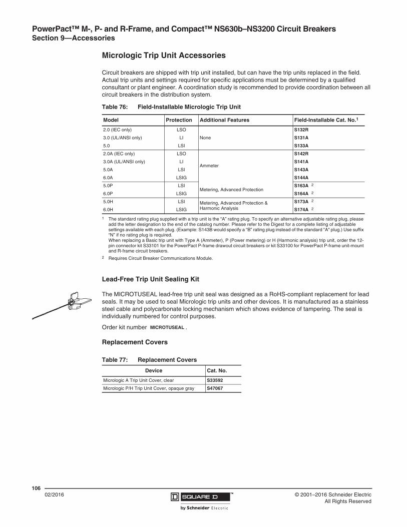
PowerPact™ M-, P- and R-Frame, and Compact™ NS630b–NS3200 Circuit Breakers Section 9—Accessories
10602/2016 ™ © 2001–2016 Schneider Electric
All Rights Reserved
Micrologic Trip Unit Accessories
Circuit breakers are shipped with trip unit installed, but can have the trip units replaced in the field. Actual trip units and settings required for specific applications must be determined by a qualified consultant or plant engineer. A coordination study is recommended to provide coordination between all circuit breakers in the distribution system.
Lead-Free Trip Unit Sealing Kit
The MICROTUSEAL lead-free trip unit seal was designed as a RoHS-compliant replacement for lead seals. It may be used to seal Micrologic trip units and other devices. It is manufactured as a stainless steel cable and polycarbonate locking mechanism which shows evidence of tampering. The seal is individually numbered for control purposes.
Order kit number .
Replacement Covers
Table 76: Field-Installable Micrologic Trip Unit
Model Protection Additional Features Field-Installable Cat. No.1
1 The standard rating plug supplied with a trip unit is the “A” rating plug. To specify an alternative adjustable rating plug, please add the letter designation to the end of the catalog number. Please refer to the Digest for a complete listing of adjustable settings available with each plug. (Example: S143B would specify a “B” rating plug instead of the standard "A" plug.) Use suffix “N” if no rating plug is required.When replacing a Basic trip unit with Type A (Ammeter), P (Power metering) or H (Harmonic analysis) trip unit, order the 12-pin connector kit S33101 for the PowerPact P-frame drawout circuit breakers or kit S33100 for PowerPact P-frame unit-mount and R-frame circuit breakers.
2.0 (IEC only) LSO
None
S132R
3.0 (UL/ANSI only) LI S131A
5.0 LSI S133A
2.0A (IEC only) LSO
Ammeter
S142R
3.0A (UL/ANSI only) LI S141A
5.0A LSI S143A
6.0A LSIG S144A
5.0P LSIMetering, Advanced Protection
S163A 2
2 Requires Circuit Breaker Communications Module.
6.0P LSIG S164A 2
5.0H LSI Metering, Advanced Protection & Harmonic Analysis
S173A 2
6.0H LSIG S174A 2
Table 77: Replacement Covers
Device Cat. No.
Micrologic A Trip Unit Cover, clear S33592
Micrologic P/H Trip Unit Cover, opaque gray S47067
MICROTUSEAL

PowerPact™ M-, P- and R-Frame, and Compact™ NS630b–NS3200 Circuit BreakersSection 9—Accessories
10702/2016™© 2001–2016 Schneider Electric
All Rights Reserved
Neutral Current Transformer (CT)
Current transformers are available for applications requiring ground-fault protection on three-phase, four-wire systems or for neutral protection and metering. Neutral current transformers are not required on non-ground-fault circuit breakers, or on three-phase, three-wire systems. The rating of the external neutral current transformer must be compatible with the rating of the circuit breaker.
NOTE: These neutral current transformers cannot be used for SGR (Source Ground-Return) or MDGF (Modified Differential Ground Fault) applications.
Ground-Fault Interface Module
The ground-fault interface module (P-frame, R-frame and NS630b–NS3200 circuit breakers only) is used to sum the current flow in three-phase, four-wire systems and multiple-sourced systems, using one or more specially-designed external current sensors to measure current flow. The ground-fault interface module is commonly used in two applications:
• For a ground-source return ground-fault sensing (SGR) system
• For a modified differential ground-fault (MDGF) system
More complex systems are possible, for information about these, contact a field sales representative.
Order kit number .
External Sensor for SGR or MDGF Protections
For use on 400 A sensor or higher.
In SGR applications, an external sensor is installed around the connection of the transformer neutral point to ground. Its secondary is connected to the Micrologic™ 6.0A, 6.0P or 6.0H trip units.
In MDGF applications, a sensor is installed on each phase and neutral conductor. The sensors for each circuit breaker are connected to an interface module. These, in turn, connect to the Micrologic 6.0A, 6.0P or 6.0H trip units.
Order kit number .
Table 78: Neutral Current Transformer Catalog Numbers
Circuit Breaker Sensor Cat. No.
P-Frame250 S33575
400–1600 S33576
R-Frame
250 S48916
400–1600 S34036
2000 S48896
2500 S48182
All All NCTWIRING 1
1 Included with NCT.
12-pin Trip Unit Connector S33100
S48891
S33579

PowerPact™ M-, P- and R-Frame, and Compact™ NS630b–NS3200 Circuit Breakers Section 9—Accessories
10802/2016 ™ © 2001–2016 Schneider Electric
All Rights Reserved
Sensor Plugs
Sensor plugs are used to set the current rating (In) of the PowerPact P- and R-frame circuit breakers.
Beginning in January 2007 (date code 07011), the sensor plugs are field-replaceable, down to 50% of the original rating. Mechanical keying in the circuit breaker prevents changing a rating plug to a higher rating than the original factory-installed sensor plug.
Rating Plugs
Interchangeable rating plugs are available to limit the long-time threshold setting range for greater versatility.
Table 79: Sensor Plugs
Circuit BreakerOriginal Circuit Breaker Amperage
Sensor Plug Range
Sensor Plug Catalog No.
UL P-Frame
250 A 250 A S47052
400 A 400 A S47053
600 A 600 A S48823
800 A 600–800 A S33092
1000 A 600–1000 A S33093
1200 A 600–1200 A S48824
IEC P-Frame
630 A 630 A S33091
800 A 600–800 A S33092
1000 A 600–1000 A S33093
1250 A 600–1250 A S33094
1600 A 600–1600 A S33095
UL R-Frame
600 A 600 A S48823
800 A 600–800 A S33092
1000 A 600–1000 A S33093
1200 A 600–1200 A S48824
1600 A 800–1600 A S33095
2000 A 1000–2000 A S33982
2500 A 1200–2500 A S33983
3000 A 1200–3000 A S48825
IEC R-Frame
1600 A 1600 A S33095
2000 A 1600–2000 A S33982
2500 A 1600–2500 A S33983
3200 A 1600–3200 A S33984
Table 80: Rating Plug Settings
Rating Plug Switch Settings Ir = In x... Cat. No.
For P-Frame and R-Frame Circuit Breakers
Type A
Type B
Type C
Type D
0.4
0.4
0.42
0.4
0.45
0.44
0.50
0.48
0.5
0.5
0.53
0.64
0.6
0.56
0.58
0.7
0.63
0.63
0.67
0.8
0.7
0.75
0.75
0.9
0.8
0.88
0.83
0.93
0.9
0.95
0.95
0.95
1
1
1
1
S48818
S48819
S48820
S48836
Type E
Type F
Type G
Type H
0.6
0.84
0.66
0.48
0.7
0.86
0.68
0.5
0.75
0.88
0.7
0.52
0.8
0.9
0.72
0.54
0.85
0.92
0.74
0.56
0.9
0.94
0.76
0.58
0.93
0.96
0.78
0.6
0.95
0.98
0.8
0.62
1
1
0.82
0.64
S48837
S48838
S48839
S48840
For NS630b–NS3200 Circuit Breakers
Type R1
Type S
Type T
0.4
0.4
0.8
0.5
0.45
0.82
0.6
0.5
0.85
0.7
0.55
0.88
0.8
0.6
0.9
0.9
0.65
0.92
0.95
0.7
0.95
0.98
0.75
0.98
1
0.8
1
S33542
S33543
S33544
Type P (Off Plug) No Long-Time Protection. S33545

PowerPact™ M-, P- and R-Frame, and Compact™ NS630b–NS3200 Circuit BreakersSection 9—Accessories
10902/2016™© 2001–2016 Schneider Electric
All Rights Reserved
Modbus Circuit Breaker Communication Module (BCM-ULP)
The circuit breaker communication module is independent of the trip unit. Installed on the circuit breaker, behind the trip unit, it receives and transmits information on the communication network. An optical link is used for communication with the Micrologic A, P, and H trip units. Power requirements are 30 mA, 24 Vdc.
NOTE: The power supply for the circuit breaker communication module must be separate and isolated from the power supply for the trip unit.
The following may be connected to this module:
• A set of dedicated switches which read the status of the circuit breaker.
• A set of “actuators” (MX shunt trip or motor mechanism) to control the circuit breaker..
Table 81: Circuit Breaker Communication Module Characteristics
Circuit Breaker Identification
ID Code, AddressSize, Rating, PerformanceType of Trip UnitType of Long-Time Rating Plug
Status Indication On/Off IndicationFault Trip
Controls Opening/Closing
Circuit Breaker and Trip Unit
A P H
Settings
Reading of Settings on Rotary Switches
Fine Settings in the Range Imposed by the Rotary Switches
Setting of Protection and Alarms
Customized Alarm Programming
X X
X
X
X
X
X
X
Operating and Maintenance Aids
Reading of Protection and Alarms
Standard
Set
Customized
X
X
X
X
X
Reading of Measurements
Current
Voltages, Frequency, Power, etc.
Power Quality: Fundamentals and Harmonics
X X
X
X
X
X
Waveform Capture X
HistoriesHistory of Trips and Alarms1
Log of Trips and Alarms
X X
X
IndicatorsContact Wear, Counters, Etc.
Maintenance Record
X X
X
1 Up to 10 trips and 10 alarms.
Table 82: Trip Unit Field-Installable Accessories
Description
Factory-Installed Cat. No. Suffix
Field-Installable Kit Cat. No.
P-Frame R-Frame
Unit Mount
I-Line™Motor
OperatedDrawout
With Rotary Handle
Unit Mount
I-Line
Circuit Breaker Communication Module (BCM) (Modbus) E1 S64205 S64207 S64206 S64205
Two Programmable Contacts Module (M2C) V S64273
Six Programmable Contacts Module (M6C) W S64204 S64202 S64204 S64201
External Voltage Sensing (EVS) YV S64203 S64210 S64209 S64210 S64208
Trip Unit Battery for Trip Indicator Lights — S33593
12-pin Trip Unit Connector for P- and R-Frame Circuit Breakers — S33100

PowerPact™ M-, P- and R-Frame, and Compact™ NS630b–NS3200 Circuit Breakers Section 9—Accessories
11002/2016 ™ © 2001–2016 Schneider Electric
All Rights Reserved
M2C and M6C Programmable Contacts
The M2C and M6C contacts are used with the Micrologic P and H control units, and indicate the type of fault and instantaneous or delayed threshold overruns (i.e: trip unit protection pickup, current/voltage unbalance, under/over voltage, reverse power, phase rotation, under/over frequency, and load shedding). The M2C has two programmable contacts while the M6C has six. They require an external 24 Vdc power supply (100 mA consumption).
NOTE: The M2C and M6C may use the same 24 V power supply as the trip unit. The M2C, M6C and trip unit power supply must be separate and isolated from the power supply used for the BCM/CCM.
M6C contacts are programmed via the control unit using a keypad or via a supervisory station with the COM communication option. They may be programmed:
• With instantaneous return to the initial state
• Without return to the initial state
• With return to the initial state following a delay
Zone-Selective Interlocking (ZSI)
Table 83: Characteristics for M2C and M6C Programmable Contacts
Minimum Load 100 mA/24 V
Breaking Capacity at aPower Factor (p.f.) of 0.7
240 Vac 5 A
380 Vac 3 A
24 Vdc 1.8 A
48 Vdc 1.5 A
125 Vdc 0.4 A
250 Vdc 0.15 A
Table 84:
ZSI is used to reduce the stress on electrical distribution equipment during fault conditions by reducing the time it takes to clear the fault, while maintaining system coordination between overcurrent protective devices.
During a short-circuit or ground-fault condition on a ZSI system, the device directly ahead of the fault sends a signal upstream via control wiring to restrain upstream circuit breakers from tripping and then trips with no intentional time delay to clear the fault. Upstream devices which receive a restraint signal obey their short-time and/or ground-fault delay settings to maintain coordination in other areas of the system. Upstream devices that do not receive a restraint signal trip with no intentional time delay.
• Fault 1—The upstream circuit breaker (A) will clear the fault with no intentional delay, regardless of its time-delay setting.
• Fault 2—Circuit breaker (B) will inform upstream circuit breaker (A) that it is clearing the fault. This will prevent circuit breaker (A) from tripping instantaneously. Circuit breaker (A) will trip at the end of its time delay setting if the fault is not cleared during this time.
ZSI requires trip settings be coordinated so a downstream circuit breaker will trip before an upstream circuit breaker under overload, short-circuit or ground-fault conditions. Effective coordination requires a system coordination study. See data bulletin 0100DB0501, Short Circuit Coordination for Low-Voltage Circuit Breakers.
Z1Z2Z3Z4Z5
Z1Z2Z3Z4Z5
Z1Z2Z3Z4Z5
Z1Z2Z3Z4Z5
Fault 1
Fault 2
Downstream Circuit Breakers
Upstream Circuit Breaker
A
B

PowerPact™ M-, P- and R-Frame, and Compact™ NS630b–NS3200 Circuit BreakersSection 9—Accessories
11102/2016™© 2001–2016 Schneider Electric
All Rights Reserved
Restraint Interface Module (RIM)
The restraint interface module (RIM) is used to allow zone-selective interlocking communications between circuit breakers with old Micrologic, Merlin Gerin™, or Federal Pioneer™ trip units and GC series ground-fault relays. For 120 Vac/24 Vdc systems, use catalog number S48890. For 240 Vac/24 Vdc systems, use catalog number S48895.
Downstream circuit breakers with Micrologic 2.0A, 5.0A, 5.0P, 5.0H, 6.0A, 6.0P, and 6.0H trip units can restrain up to fifteen upstream circuit breakers with Micrologic 5.0A, 5.0P, 5.0H, 6.0A, 6.0P, and 6.0H trip units without requiring a restraint interface module. If the number of upstream circuit breakers exceeds fifteen, then a RIM is required.
External Power Supply Module
When used with the Micrologic A, P, and H trip units, a power supply module makes it possible to:
• Display currents less than 20% of sensor (In).
• Maintain display of tripping causes after opening of the circuit breaker.
• Store the value of the interrupted current (P and H trip units only).
• The modules are not UL Listed.
External Battery Backup Module
The external battery backup module (Catalog No. 685831) provides up to twelve hours of backup power for the power supply module.
Table 85: RIM Requirements1
1 R = RIM is required.Number denotes maximum number of upstream circuit breakers that can be restrained without requiring a RIM.
Mic
rolo
gic
trip
un
it2
Mic
rolo
gic
S
erie
s B
tri
p u
nit
Sq
uar
e D
G
C-1
00 r
elay
Sq
uar
e D
GC
-200
rel
ay
Mer
lin G
erin
S
TR
58 t
rip
un
its
Fede
ral P
ion
eer
US
RC
an
d U
SR
CM
trip
uni
ts
Micrologic Trip Unit2
2 Includes 2.0A (as a downstream trip unit only), 5.0A, 5.0P, 5.0P, 5.0H, 6.0A, 6.0P, and 6.0H trip units.
15 R R 15 15 R
Square D Micrologic Series B Trip Units R 26 R R R 15
Square D GC-100 Relay R R 7 R R R
Square D GC-200 Relay 15 R R 15 15 R
Merlin Gerin STR58 Trip Units 15 R R 15 15 R
Merlin Gerin STR53 Trip Units 15 R R 15 15 R
Federal Pioneer USRC and USRCM Trip Units R 15 R R R 15
Square D Add-on Ground Fault Module for Equipment Protection R 5 R R R R
Table 86: External Power Supply Module
Power Supply Input (+10%, -15%)
Output Voltage
Output Power
Cat. No.
24–30 Vdc Input
24 Vdc5 VA/5 W
(Ripple < 5%)
685823
48/60 Vdc Input 685824
125 Vdc Input 685825
110–130 Vac Input 685826
200–240 Vac Input 685827
380–415 Vac Input 685829
Upstream Device(Receives input from RIM)
Downstream Device(Sends output to RIM)

PowerPact™ M-, P- and R-Frame, and Compact™ NS630b–NS3200 Circuit Breakers Section 9—Accessories
11202/2016 ™ © 2001–2016 Schneider Electric
All Rights Reserved
Test Equipment
Hand-Held Test Kit
The hand held test kit may be used to:
• Verify trip unit operation, the mechanical operation of the circuit breaker, and the electrical continuity of the connection between the tripping coil and the trip unit.
• Supply control power to the trip unit for settings via the keypad when the circuit breaker is open (Micrologic P and H trip units).
• Inhibit thermal imaging for primary injection test (for Micrologic types A, P or H).
• Inhibit ground fault for primary injection test (for Micrologic types A, P or H).
• Self-restrain Zone-Selective Interlocking (ZSI) (for Micrologic types A, P or H).
Full-Function Test Kit
The full-function test kit consists of a signal-injection box which can be used alone or with a supporting personal computer (PC). The optional test kit software is compatible with Windows® 95, 98 and Windows NT® operating systems.
The test kit without a supporting PC may be used to check:
• The mechanical operation of the circuit breaker
• The electrical continuity of the connection between the tripping coil and the trip unit
• Trip unit operation — for example:
— Display of settings
— Operating tests on the electronic component
— Automatic and manual tests on protection functions (trip curve verification)
— Tests on the Zone-Selective Interlocking (ZSI) function
— Inhibition of the ground-fault protection for equipment
— Inhibition of the thermal imaging
• Save test data into test kit
The test kit with a supporting PC may be used to:
• Print test data
• Compare the real tripping curve with the curves available on the PC
Table 87: Hand-held Test Kit Catalog Numbers
Device Cat. No.
Hand-held Test Kit S33594
Seven-pin Test Cable (for Connection Between Test Kit and Trip Unit)1
1 Included in the test kit. Kit for replacement only.
S48907
Two-pin Test Cable (for Connection Between Test Kit and Trip Unit) S48908
Table 88: Full-Function Test Kit Catalog Numbers
Device Cat. No.
Full-function Test Kit S33595
Seven-pin Test Cable (for Connection Between Test Kit and Trip Unit)1
1 Included in the test kit. Kit for replacement only.
S48907
230 Vac Filtered Power Cord1 S48856
120 Vac Filtered Power Cord1 S48855
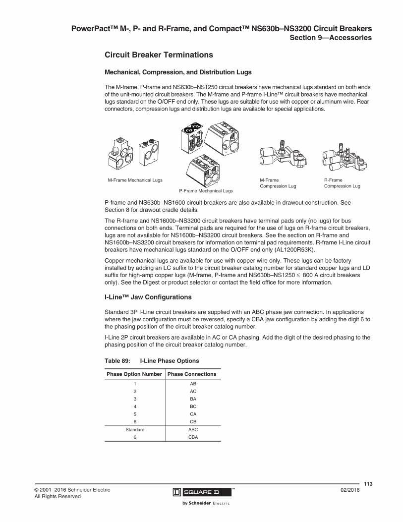
PowerPact™ M-, P- and R-Frame, and Compact™ NS630b–NS3200 Circuit BreakersSection 9—Accessories
11302/2016™© 2001–2016 Schneider Electric
All Rights Reserved
Circuit Breaker Terminations
Mechanical, Compression, and Distribution Lugs
The M-frame, P-frame and NS630b–NS1250 circuit breakers have mechanical lugs standard on both ends of the unit-mounted circuit breakers. The M-frame and P-frame I-Line™ circuit breakers have mechanical lugs standard on the O/OFF end only. These lugs are suitable for use with copper or aluminum wire. Rear connectors, compression lugs and distribution lugs are available for special applications.
P-frame and NS630b–NS1600 circuit breakers are also available in drawout construction. See Section 8 for drawout cradle details.
The R-frame and NS1600b–NS3200 circuit breakers have terminal pads only (no lugs) for bus connections on both ends. Terminal pads are required for the use of lugs on R-frame circuit breakers, lugs are not available for NS1600b–NS3200 circuit breakers. See the section on R-frame and NS1600b–NS3200 circuit breakers for information on terminal pad requirements. R-frame I-Line circuit breakers have mechanical lugs standard on the O/OFF end only (AL1200R53K).
Copper mechanical lugs are available for use with copper wire only. These lugs can be factory installed by adding an LC suffix to the circuit breaker catalog number for standard copper lugs and LD suffix for high-amp copper lugs (M-frame, P-frame and NS630b–NS1250 ≤ 800 A circuit breakers only). See the Digest or product selector or contact the field office for more information.
I-Line™ Jaw Configurations
Standard 3P I-Line circuit breakers are supplied with an ABC phase jaw connection. In applications where the jaw configuration must be reversed, specify a CBA jaw configuration by adding the digit 6 to the phasing position of the circuit breaker catalog number.
I-Line 2P circuit breakers are available in AC or CA phasing. Add the digit of the desired phasing to the phasing position of the circuit breaker catalog number.
Table 89: I-Line Phase Options
Phase Option Number Phase Connections
1
2
3
4
5
6
AB
AC
BA
BC
CA
CB
Standard
6
ABC
CBA
M-Frame Mechanical Lugs
P-Frame Mechanical Lugs
M-Frame Compression Lug
R-Frame Compression Lug

PowerPact™ M-, P- and R-Frame, and Compact™ NS630b–NS3200 Circuit Breakers Section 9—Accessories
11402/2016 ™ © 2001–2016 Schneider Electric
All Rights Reserved
Power Distribution Connectors
Power distribution connectors (PDCs) are available for M-frame, P-frame and NS630b–NS1250 unit-mount circuit breakers as field-installable kits. They can be used for multiple load wire connections on one circuit breaker. Each is UL Listed for copper wire only. Power distribution connectors are for use on the O/OFF end of the circuit breaker only, and the O/OFF end must be connected to the load. PDCs are for use in UL508 applications only.
Control Wire Terminations
Mechanical lug kits are available with provisions for control wire terminations. The control wire is crimped to a standard ring-type wire crimp terminal (not included) and secured to the lug using the #6-32 screw included in the kit. These lugs are UL and CSA Recognized as a circuit breaker component.
These lugs are available factory installed or as field-installable kits. For factory-installed control wire terminations, add the suffix from the table below in the lug option field of the catalog number.
PDC6P20 PDC12P4
Table 90: Control Wire Termination
Termination Code Control Wire Location Control Wire Suffix
L Both ends LW
M ON end only LU
P OFF end only LV
Table 91: Lug Kits
Lug TypeCatalog Number
Used OnCircuit Breaker Type
Lugs Per Kit1
Max. Amp.Rating
Conductors/Lug
No. Range
Aluminum Mechanical Lug2
AL800M23K M-Frame, P-Frame ≤ 800 A,NS630b–NS800
Unit-Mount,I-Line 3, 4 800 3 3/0 AWG–500 kcmil
(95–250 mm2)
AL800P6K M-Frame, P-Frame ≤ 800 A3,NS630b–NS800
Unit-Mount,I-Line 3, 4 800 2 3/0 AWG–600 kcmil
(95–300 mm2)
AL800P7K M-Frame, P-Frame ≤ 800 A3,NS630b–NS800
Unit-Mount,I-Line 3 770 2
3/0 AWG–750 kcmil (95–400 mm2);Compact AL 750 kcmil (400 mm2) only
AL1200P24K M-Frame, P-Frame > 800 A3, optional for P-Frame≤ 800 A, NS630b–NS1200
Unit-mount,I-Line
1 1200 4 3/0 AWG–500 kcmil(95–250 mm2)
AL1200P25K P-Frame > 800 A, optional for P-Frame ≤ 800 A, NS630b–NS1200
Unit-Mount 3, 4 1200 4 3/0 AWG–500 kcmil(95–250 mm2)
AL1200R53K R-Frame,NS1600b–NS3200
I-Line 1 1200 4 3/0 AWG–600 kcmil(95–300 mm2)
AL1200P6KU P-Frame > 800 A, optional for P-Frame ≤ 800 A, NS630b–NS1200
Unit-Mount 3 1200 3 350-600 kcmil(185-300 mm2)
AL1200P7KU P-Frame ≤ 800 A3,NS630b–NS800 Unit-Mount 3 1155 3
3/0 AWG–750 kcmil (95–400 mm2); Compact AL 750 kcmil only
AL2500RK R-Frame,NS1600b–NS3200 Unit-Mount 2 2500 1 1/0 AWG–750 kcmil
(50–400 mm2)
Continued on next page

PowerPact™ M-, P- and R-Frame, and Compact™ NS630b–NS3200 Circuit BreakersSection 9—Accessories
11502/2016™© 2001–2016 Schneider Electric
All Rights Reserved
Copper Mechanical Lugs4
CU800M23K M-Frame, P-Frame ≤ 800 A,NS630b–NS800
Unit-Mount,I-Line 3, 4 800 3
3/0 AWG–500 kcmil(95–250 mm2)
CU1200P24K M-Frame, P-Frame > 800 A, optional for ≤ 800 A, NS630b–NS1200
Unit-Mount,I-Line 1 1200 4
3/0 AWG–500 kcmil(95–250 mm2)
CU1200P25K P-Frame > 800 A, optional for ≤ 800 A,NS630b–NS1200 Unit-Mount 3, 4 800 4
3/0 AWG–500 kcmil(95–250 mm2)
CU1200R53K R-Frame,NS1600b–NS3200 I-Line 1 1200 4
3/0 AWG–600 kcmil(95–300 mm2)
CU250P1K M-Frame, P-Frame ≤ 800 A,NS630b–NS800 PJ 3 150 A 1
1–1/0 AWG(50 mm2)
Aluminum Compression Lugs
YA250P3 M-Frame, P-Frame,NS630b–NS1200
Unit-Mount,I-Line 1 250 1
2/0 AWG–300 kcmil(70–150 mm2)
YA400P3 M-Frame, P-Frame,NS630b–NS1200
Unit-Mount,I-Line 2 400 1
2/0 AWG–300 kcmil(70–150 mm2)
YA1200R3 R-Frame,NS1600b–NS3200 I-Line 4 1200 1
2/0 AWG–300 kcmil(70–150 mm2)
YA300P5 M-Frame, P-Frame,NS630b–NS1200
Unit-Mount,I-Line 1 300 1
4/0 AWG–500 kcmil(95–240 mm2)
YA600P5 M-Frame, P-Frame,NS630b–NS1200
Unit-Mount,I-Line 2 600 1
4/0 AWG–500 kcmil(95–240 mm2)
YA1200R5 R-Frame,NS1600b–NS3200 I-Line 4 1200 1
4/0 AWG–500 kcmil(95–240 mm2)
YA400P7 M-Frame, P-Frame,NS630b–NS1200
Unit-Mount,I-Line 1 400 1
500–750 kcmil(240–400 mm2)
YA800P7 M-Frame, P-Frame,NS630b–NS1200
Unit-Mount,I-Line 2 800 1
500–750 kcmil(240–400 mm2)
YA1200R7 R-Frame,NS1600b–NS3200 I-Line 4 1200 1
500–750 kcmil(240–400 mm2)
YA2500R7 R-Frame,NS1600b–NS3200 Unit-Mount 2 2500 1
500–750 kcmil(240–400 mm2)
Copper
Compression Lugs4
CYA400P5 M-Frame, P-Frame,NS630b–NS1200
Unit-Mount,I-Line 1 400 1
4/0 AWG–500 kcmil(95–240 mm2)
CYA600P5 M-Frame, P-Frame,NS630b–NS1200
Unit-Mount,I-Line 2 600 1
4/0 AWG–500 kcmil(95–240 mm2)
CYA1200R5 R-Frame,NS1600b–NS3200 I-Line 4 1200 1
4/0 AWG–500 kcmil(95–240 mm2)
CYA800R7 M-Frame, P-Frame,NS630b–NS1200 I-Line 2 800 1
500–750 kcmil(240–400 mm2)
CYA1200R7 R-Frame,NS1600b–NS3200 I-Line 4 1200 1
500–750 kcmil(240–400 mm2)
Power Distribution Connectors (Copper Only)
PDC12P4 M-Frame, P-Frame,NS630b–NS1200
Unit-Mount,I-Line 3 400 12
10–4 AWG (6–25 mm2)
PDC12P44 M-Frame, P-Frame,NS630b–NS1200
Unit-Mount,I-Line 4 400 12
10–4 AWG (6–25 mm2)
PDC6P20 M-Frame, P-Frame,NS630b–NS1200
Unit-Mount,I-Line 3 600 6
12–2/0 AWG(25–70 mm2)
PDC6P204 M-Frame, P-Frame,NS630b–NS1200
Unit-Mount,I-Line 4 600 6
12–2/0 AWG(25–70 mm2)
1 For 4P circuit breakers, add “4” to kit catalog number (AL800M23K4 instead of AL800M23K).2 For version with tapped hole for control wire add a T before the K to the kit catalog number (AL800M23TK instead of AL800M23K).3 Does not fit onto I/ON end of unit-mount P-frame circuit breakers.4 Not available with tapped hole for control wire.
Table 91: Lug Kits (continued)
Lug TypeCatalog Number
Used OnCircuit Breaker Type
Lugs Per Kit1
Max. Amp.Rating
Conductors/Lug
No. Range

PowerPact™ M-, P- and R-Frame, and Compact™ NS630b–NS3200 Circuit Breakers Section 9—Accessories
11602/2016 ™ © 2001–2016 Schneider Electric
All Rights Reserved
External Accessories
Phase Barriers
Phase barriers are available for M-frame, P-frame and NS630b–NS1600 unit-mount circuit breakers with bus connections or with lugs ≤ 800 A. Phase barriers are also available for R-frame and NS1600b–NS3200 unit-mount circuit breakers.
Electric Joint Compound
I-Line circuit breakers, I-Line busway plug-on units and I-Line panelboards and switchboards are supplied with factory-applied joint compound on the plug-on connectors. The compound is especially formulated for I-Line connections and contributes to the overall performance of the connection.
If the joint compound is removed, it must be reapplied. A two-ounce container of the compound (Cat. No. PJC7201) is available.
Door-Mounted Operating Mechanisms
Door-mounted operating mechanisms are available for M- and P-frame circuit breakers. The Type L door-mounted variable-depth operating mechanism feature heavy-duty, all-metal constructions. They can be padlocked in the OFF position when the enclosure door is open. Handle assemblies can be locked OFF with up to three padlocks, which also locks the door closed. Complete kits include a handle assembly, operating mechanism, and shaft assembly, and are rated for NEMA Type 1, 3R and 12 enclosures. A door drilling template is supplied for ease of installation.
Handle Extension
Handle extensions are available for M- and P-frame circuit breakers. Order catalog number 33195.
Table 92: Phase Barriers
Used With Cat. No. Qty Per Kit
M-Frame and P-Frame S336463
R-Frame S33998
Operating Mechanism
Handle Assembly
Table 93: Door-Mounted Operating Mechanisms
Description Description Handle Assembly1
1 Painted handles are painted flat black, with the base ring silver.
Shaft Mounting Depth Cat. No.
Circuit Breaker Mechanism Type L
Painted, 8 inch 7.2–11.625 in.(182–295 mm) LW1
Painted, 8 inch 7.2–22.25 in.(182–565 mm)
LW4
Handle Assembly2
2 Due to gasketing, NEMA 3 and 4 handle assemblies are NOT trip indicating.
Type 3, 4 Painted, 8 inch 7.2–11.625 in.(182–295 mm)
LHP48
Type 3, 4, 4X Chrome Plated, 8 inch LCP48
Replacement Parts
Handle Assembly Painted, 8 inch — LHP8
Operating Mechanism — — LW7
Standard Shaft —7.2–11.625 in.(182–295 mm) LS8
Long Shaft —7.2–22.25 in.
(182–565 mm) LS10

PowerPact™ M-, P- and R-Frame, and Compact™ NS630b–NS3200 Circuit BreakersSection 9—Accessories
11702/2016™© 2001–2016 Schneider Electric
All Rights Reserved
Rotary Operating Handles
P-frame and NS630b–NS1600 circuit breakers are available with standard black directly-mounted (IP-40) or door-mounted / telescopic door-mounted (IP-55) rotary handles. The rotary handles are factory-installed and available with two early-break or two early-make contacts.
Replacement Handles
Replacement handle assemblies are available for R-frame and NS1600b–NS3200 circuit breakers. Replacement toggle handle extensions, including an optional longer handle extension, are available for M-frame, P-frame, and NS630b–NS1600 circuit breakers.
Door Escutcheons
Accessory cover door escutcheons are available for all M-frame, P-frame, R-frame and NS630b–NS3200 circuit breakers. Toggle door escutcheons are also available for fixed-mounted, P-frame, manually-operated circuit breakers.
Locking Accessories
Field-installable handle padlock attachments are available for manually-operated circuit breakers. These attachments will accommodate three padlocks with a shackle diameter of 3/16–5/16 in. (5–8 mm) and will lock the circuit breaker in the O/OFF position only.
A handle padlock attachment is also available for locking manually-operated circuit breakers in either the I/ON or O/OFF position. This attachment will accommodate three padlocks with a shackle diameter of 3/16–5/16 in. (5–8 mm) and is available as factory or field installation.
Kirk® key interlock brackets are also available for locking circuit breakers in the O/OFF position only. Not available for drawout P-frame or NS630b–NS1600.
Circuit breakers with rotary handles come standard with provision for padlocking the handle in the O/OFF position only. Key locks are also available for locking the circuit breaker in the I/ON or O/OFF positions.
A keylock or padlock provision for padlocking the circuit breaker in the O/OFF position is optional on electrically-operated P-frame and NS-630b–NS1600 circuit breakers.
Table 94: Rotary Operated Handles
Device SwitchesFactory-InstalledCat. No. Suffix
Direct Mounted, Standard Black Handle — RD10
Two Early-Break and Two Early-Make Switches RD16
Door Mounted, Standard Black Handle— RE10
Two Early-Break and Two Early-Make Switches RE16
Rotary Handle Replacement Kit — S33875
Table 95: Replacement Handles for M-, P-, and R-Frame Circuit Breakers
Description Frame Field-Installed Cat. No.
Standard R-Frame S33997
Standard Short M-, P-Frame S46998
Long M-, P-Frame S46996
Table 96: Door Escutcheons for M-, P-, and R-Frame Circuit Breakers
Description Frame Field-Installed Cat. No.
Accessory CoverM-, P-Frame S33718
R-Frame S33929
Toggle Handle M-, P-Frame S33717
Drawout P-Frame S33857

PowerPact™ M-, P- and R-Frame, and Compact™ NS630b–NS3200 Circuit Breakers Section 9—Accessories
11802/2016 ™ © 2001–2016 Schneider Electric
All Rights Reserved
Sub-Feed Lugs
Sub-feed lug kits are UL Listed for use on Listed equipment. They have plug-on jaw construction and plug on to the I-Line bus stack in the same manner as branch circuit breakers. Lugs on these devices accommodate the same wire sizes as the equivalent ampere rated circuit breakers.
Table 97: Locks and Interlocking
M- and P-Frame R-Frame
Device DescriptionFactory-InstalledCat. No. Suffix
Field-InstalledCat. No.
Factory-InstalledCat. No. Suffix
Field-InstalledCat. No.
Handle Padlocking Device
Removable (Lock Off or On) — — — —
Removable (Lock Off Only) — S44936 — S33996
Fixed (Lock Off or On) YP S32631 YP S32631
Fixed (Lock Off Only) YQ MPRPAF YQ MPRPAF
Interlocking (Not UL listed) Mechanical for Circuit Breakers with Rotary Handles1 — S33890 — —
Key Locking
Provision Only, Vertical Mount, 1 key interlock including padlock provision, open position only
Kirk JE1 — JE1 —
Provision Only, Vertical Mount, 1 or 2 Locks Kirk JA — — —
Provision Only, Horizontal Mount
1 Lock, M- and P-Frame
1 or 2 Locks, R-Frame
Kirk JK — JK —
Ronis JB — JB —
Profalux JD — JD —
Provision and 1 Lock, Vertical Mount Kirk JG — — —
Provision and 1 Lock, Horizontal Mount
Kirk JL — JL —
Ronis JC — JC —
Profalux JF — JF —
Provision and 2 Locks Keyed Alike, Vertical Mount Kirk JN — — —
Provision and 2 Locks Keyed Alike, Horizontal Mount
Kirk — — JN —
Provision and 2 Locks Keyed Differently, Vertical Mount Kirk JP — — —
Provision and 2 Locks Keyed Differently, Horizontal Mount Kirk — — JP —
1 Not available on M-frame, motor-operated P-frame, or I-Line circuit breakers.
Table 98: I-Line Sub-Feed Lug Kit Terminations
Plug-On Lug Kit Cat. No.
PolesMounting Height
Ampere Rating
Lug
Catalog No. Wire Size Conductors Per Lug
SL800M5 3 800 A —3/0 AWG–500 kcmil(95–240 mm2) 3
SL1200P5 3 1200 A — 3/0 AWG–500 kcmil(95–240 mm2)
4
SL1200P6 3 1200 A — 350–600 kcmil(185–300 mm2) 3
SL1200P7 3 1200 A —3/0 AWG–750 kcmil(95–400 mm2) 2
S33931 3 9 in. 1200 A AL1200P24K 3/0 AWG–500 kcmil(95–240 mm2)
4
S33930 3 15 in. 1200 A AL1200R53K 3/0 AWG–600 kcmil(95–300 mm2) 4

PowerPact™ M-, P- and R-Frame, and Compact™ NS630b–NS3200 Circuit BreakersSection 10—P-Frame Cradles and Cradle Accessories
11902/2016™© 2001–2016 Schneider Electric
All Rights Reserved
Section 10—P-Frame Cradles and Cradle Accessories
Circuit Breaker and Cradle Design
Drawout Mechanism
The drawout assembly mechanism allows the circuit breaker to be racked in four positions (connected, test, disconnected, or withdrawn), as shown in the figure below.
0612
3146
A—Terminal CoverB—Lifting TabsC—Extension Rail HandleD—Padlock ProvisionE—Position IndicatorF—Crank Insertion OpeningG—Stop Release ButtonH—Crank Storage Space
B
Drawout Circuit Breaker
Cradle
B
A
C
H
G
F
E
D
NOTE: See page 19 for cradle catalog numbers.
Connected Position Test Position Disconnected Position Withdrawn Position
Secondary Contacts Clusters (UL)
Stabs (UL)
NOTE: For UL/CSA Listed devices, the clusters are mounted on the circuit breaker and the stabs are on the cradle. For IEC devices, the clusters are mounted on the cradle and the stabs are mounted on the circuit breaker.
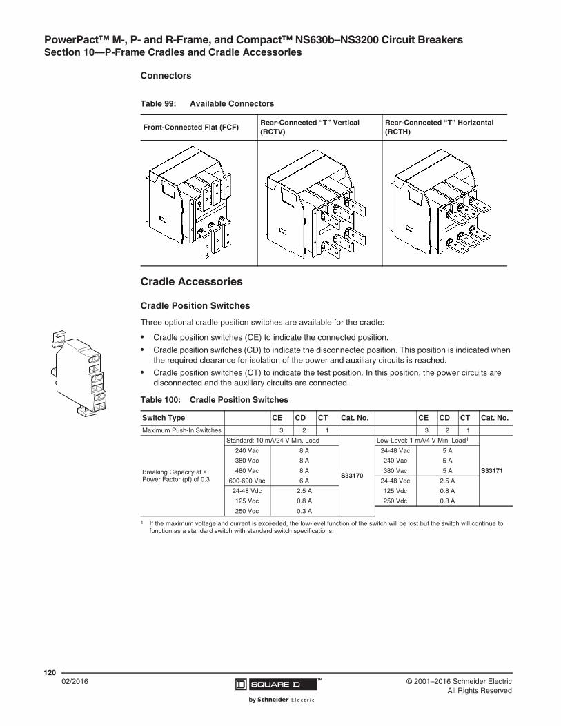
PowerPact™ M-, P- and R-Frame, and Compact™ NS630b–NS3200 Circuit Breakers Section 10—P-Frame Cradles and Cradle Accessories
12002/2016 ™ © 2001–2016 Schneider Electric
All Rights Reserved
Connectors
Cradle Accessories
Cradle Position Switches
Three optional cradle position switches are available for the cradle:
• Cradle position switches (CE) to indicate the connected position.
• Cradle position switches (CD) to indicate the disconnected position. This position is indicated when the required clearance for isolation of the power and auxiliary circuits is reached.
• Cradle position switches (CT) to indicate the test position. In this position, the power circuits are disconnected and the auxiliary circuits are connected.
Table 99: Available Connectors
Front-Connected Flat (FCF)Rear-Connected “T” Vertical (RCTV)
Rear-Connected “T” Horizontal (RCTH)
Table 100: Cradle Position Switches
Switch Type CE CD CT Cat. No. CE CD CT Cat. No.
Maximum Push-In Switches 3 2 1 3 2 1
Breaking Capacity at aPower Factor (pf) of 0.3
Standard: 10 mA/24 V Min. Load
S33170
Low-Level: 1 mA/4 V Min. Load1
1 If the maximum voltage and current is exceeded, the low-level function of the switch will be lost but the switch will continue to function as a standard switch with standard switch specifications.
S33171
240 Vac 8 A 24-48 Vac 5 A
380 Vac 8 A 240 Vac 5 A
480 Vac 8 A 380 Vac 5 A
600-690 Vac 6 A 24-48 Vdc 2.5 A
24-48 Vdc 2.5 A 125 Vdc 0.8 A
125 Vdc 0.8 A 250 Vdc 0.3 A
250 Vdc 0.3 A

PowerPact™ M-, P- and R-Frame, and Compact™ NS630b–NS3200 Circuit BreakersSection 10—P-Frame Cradles and Cradle Accessories
12102/2016™© 2001–2016 Schneider Electric
All Rights Reserved
Cradle Locking and Interlocking
Disconnected Position Locking
The circuit breaker can be locked in the disconnected position by key interlock (optional, catalog number ) or padlock (standard). The key interlock is on the cradle and accessible with the door locked.
• Kirk key interlocks are available for UL/CSA circuit breakers. Key is captive when circuit breaker is closed.
• Locking in all positions (disconnected, test, and connected) is possible. Factory standard setting is locking in disconnected position.
Door Interlock
The door interlock (catalog number S33786) prevents the compartment door from being opened when the circuit breaker is in the connected or test position. If the circuit breaker is put into the connected position with the door open, the door can be closed without disconnecting the circuit breaker. For greater protection, this interlock can be used in conjunction with the open door racking interlock.
Open Door Racking Interlock
The racking interlock (catalog number ) prevents racking in the circuit breaker when the door is open. (Insertion of the circuit breaker racking crank is not possible when the compartment door is open.)
Cradle Rejection Kits
The cradle rejection feature (optional, catalog number ) ensures that only the properly designated circuit breaker or switch is matched with the selected cradle assembly.
Miscellaneous Accessories
Shutter and Shutter Lock
The shutters automatically block access to the main disconnects when the circuit breaker is in the disconnected, test, or fully withdrawn position. The shutter lock is used to prevent connection of the circuit breaker or to lock the shutters in the closed position.
The optional shutter assembly (catalog number ) consists of shutter and padlock provision.
Door Escutcheon (CDP)
The door escutcheon (catalog number ) provides a frame and seal for the circuit breaker.
Transparent Cover for Door Escutcheon (CCP) (P-Frame Only)
The door escutcheon cover (catalog number ) is hinge-mounted and is designed to be installed on the door escutcheon for the P-frame drawout circuit breaker.
RON
ISRO
NIS
S33772
������
���
�����
S33788
S33767
S48933
S33857
S33859

PowerPact™ M-, P- and R-Frame, and Compact™ NS630b–NS3200 Circuit Breakers Section 10—P-Frame Cradles and Cradle Accessories
12202/2016 ™ © 2001–2016 Schneider Electric
All Rights Reserved
Wiring Diagrams
Figure 11: Terminal Layout for Push-In Connector Installation
Function Connector Description Trip Unit Type
Auxiliary Contacts OF
Open/Closed circuit breaker or switch position contacts
Basic A P H Connector Description
— X X X Com: E1-E6 Communication
Rotary Handle Contacts
CAO Early break contact — X X X UC1: Z Zone-selective Interlocking
CAF Early make contact Z1 = ZSI OUT signal
Cradle Contacts
CD Disconnected position contacts Z2 = ZSI OUT
CE Connected position contacts Z3 = ZSI IN signal
CT Test position contacts Z4 = ZSI IN short time
Remote Operation
SDE Electrical fault alarm contact Z5 = ZSI IN ground fault
SD Alarm contact — X X X UC1: M1 Modified differential ground fault (MDGF)
MN Undervoltage trip device — X X X UC2: T External neutral
MX1 Shunt trip — X X X UC2: M Modified differential ground fault (MDGF)
1 When networked MXF coils are used, terminal C3 must be connected to line even if the communication module is not installed.
— X X X UC3: F 24 Vdc external power supply (F1 -, F2 +)
— — X X UC3: Vn External neutral plug
— — X X UC4 External phase voltage sensing
— — X X M6C Six programmable contacts
CD2824822821
CD1814812811
CE3334332331
CE2324322321
CE1 CT1314 914312 912311 911
OF3343231
OF2 OF124 1422 1221 11
SD949291
CAO2524522521
Com UC1 UC2 UC3 UC4 SDEE5E3E1
E6E4E2
Z5Z3Z1
M1Z4Z2
M2T3T1
M3T4T2
F2+VNF1-
V3V2V1
544542541
848281
MN/MXD2/C12
C13 D1/C11
CAF2534532531
CAF1 CAO1514512511
M6CQ3Q2Q1
Connector Recommended Wire Size
E1–E2 22 AWG (0.3 mm2) MIN shielded pair cable or twisted pair copper wires
V1, V2, V3, Vn 22–16 AWG (0.3–1.5 mm2)
T 22 AWG (0.3 mm2) stranded shielded cable
E3–E6, Q1, Q2, Q3 22 AWG (0.3 mm2) shielded twisted pairs with drain (Belden 8723 or equal)3
OF, SD, SDE 18–16 AWG (0.8–1.5 mm2)
MN, MX 18–14 AWG (0.8–2.5 mm2)
F Size per aux 24 Vdc power supply
Z1–Z5 22 AWG (0.3 mm2)

PowerPact™ M-, P- and R-Frame, and Compact™ NS630b–NS3200 Circuit BreakersSection 10—P-Frame Cradles and Cradle Accessories
12302/2016™© 2001–2016 Schneider Electric
All Rights Reserved
Figure 12: Wiring Diagrams for Auxiliary Connections
A–Do not remove factory-installed jumpers between Z3, Z4 and Z5 unless ZSI is connected. B–Do not remove factory-installed jumper between T1 and T2 unless neutral CT is connected. Do not install jumper between T3 and T4.C–For proper wiring of neutral CT, refer to Instruction Bulletin 48041-082-01 shipped with it.D–24 Vdc power supply for trip unit must be separate and isolated from 24 Vdc power supply for communication modules.E–For proper wiring of the FDM, refer to user guide 5100512864A-02.
or
D2
D1
MN MX
C12
C11
C
13
Power Trip Unit Remote Operation
NOTE: All diagrams show circuit breaker in tripped position.
Auxiliary Contacts Cell Switches
822
824
821
812
814
811
Dis
conn
ecte
d
CD2 CD1
331
332
334
CE3
Con
nect
ed
321
322
324
CE2
311
312
314
CE1
914
912
911
CT1
Tes
t P
ositi
on
12 1411
22 2432 3431 21
OF3 OF2 OF1
Ope
n
Clo
sed
82 8481
SDE
Fau
lt
92 9491
SD
Fau
lt
542
544
541
CAF2
Clo
sed
532
534
531
CAF1
522
524
521
CAO2
Ope
n
512
514
511
CAO1
E1 E2 E3 E4 E5 E6
Circuit Breaker Communication Module (BCM)
A
DC
B
Wiring of the COM varies with available options.See Figure 13.

PowerPact™ M-, P- and R-Frame, and Compact™ NS630b–NS3200 Circuit Breakers Section 10—P-Frame Cradles and Cradle Accessories
12402/2016 ™ © 2001–2016 Schneider Electric
All Rights Reserved
Figure 13 – Wiring Diagrams for the COM Option
I/O Module
E1 E2 E3 E4 E5 E6
RedWhiteBlack
Blue
Circuit Breaker ULP cord
Circuit Breaker Communication Module (BCM)
ULP cord
Microswitches Connected to BCM
FDM121version > V2.0.2
E1 E2 E3 E4 E5 E6
customer terminal block
CCMCCM
+ -
Rx- Rx+ Tx- Tx+
B’ / R
x + D1
A’ / Rx - D
0
B / Tx + D
1
A / Tx - D0
0 V
24 V
EGX100
The B configuration is only possible with CCM marked Schneider Electric on the front face.
+ -
+ -
External power supply24 V c
+ - + -
A B A’ B’
Red Black BlueWhite
Circuit BreakerULP Cord
E1 E2 E3 E4 E5 E6
customer terminal block
Rx- Rx+ Tx- Tx+
B’ / R
x + D1
A’ / Rx - D
0
B / Tx + D
1
A / Tx - D0
0 V
24 V
EGX100+ -
CCM
+ -
+ -
+ -
External power supply24 V c
A B A’ B’
A B A’ B’
E1 E2 E3 E4 E5 E6
customer terminal block
Rx- Rx+ Tx- Tx+
B’ / R
x + D1
A’ / Rx - D
0
B / Tx + D
1
A / Tx - D0
0 V
24 V
EGX100+ -
+ -
External power supply24 V c
CCM
A B A’ B’+ -
+ -A B A’ B’
A B A’ B’
ModbusCom
Address47
Baud-rate19.2 k
4W, 2W+ULP
4wires
Micrologic P/H
Micrologic P/HModbus
Com
Address
Baud-rate19.2 k
4W, 2W+ULP
2w+ULP
A
B
Net
wor
kB
reak
er
Net
wor
kB
reak
er
Net
wor
kB
reak
er
A. Modbus RS 485 2-wirewithout ULP module
B. Modbus RS 485 2-wire + ULPwith ULP module
A. Modbus RS 485 4-wirewithout ULP module
Wiring of the COM Option (Modbus BCM ULP and CCM Modules
Wiring of the I/O Modules
Typical for all CCMs. See cell switches Page 123.

PowerPact™ M-, P- and R-Frame, and Compact™ NS630b–NS3200 Circuit BreakersSection 10—P-Frame Cradles and Cradle Accessories
12502/2016™© 2001–2016 Schneider Electric
All Rights Reserved
Figure 14: Communication Components and FDM121 Connections
LV434195 LV434196 LV434197
Circuit Breaker ULP Cord
0.98 ft.(0.35 m)
4.3 ft.(1.3 m)
9.8 ft.(3 m)
ETH1 ETH2
24VDC
+ -
External power supply24 Vdc
B’ / R
x + D1
A’ / Rx - D
0
B / Tx + D
1
A / Tx - D0
0 V
24 V
E1
Red Black Blue
OR
E2 E3 E4 E5 E6
Customer Terminal Block
White
IFM
+ -
External power supply24 Vdc
IFE
D0 = A’ / Rx-, A / Tx-D1 = B’ / Rx+, B / Tx+
Ethernet
B’ / R
x + D1
A’ / Rx - D
0
B / Tx + D
1
A / Tx - D0
0 V
24 V
E1
Red Black Blue
E2 E3 E4 E5 E6
Customer Terminal Block
White
Modbus-SL
AB
C
D
F C
D
FE E
A. Modbus NetworkB. Ethernet NetworkC. Circuit Breaker ULP CordD. FDM DisplayE. ULP TerminationF. ULP Cable
ConnectionsPowerPact and Compact circuit breakers are connected to the ULP devices (FDM121 display, IFM, IFE or I/O module) via the circuit breaker ULP cord.
• Cord is available in three lengths: 0.98 ft. (0.35 m), 4.3 ft. (1.3 m) and 9.8 ft. (3 m).
• Lengths up to 32.9 ft. (10 m) are possible using extensions.

PowerPact™ M-, P- and R-Frame, and Compact™ NS630b–NS3200 Circuit Breakers Section 11—Circuit Breaker Dimensional Drawings
12602/2016 ™ © 2001–2016 Schneider Electric
All Rights Reserved
Section 11—Circuit Breaker Dimensional Drawings
Dimensions for M-Frame Circuit Breakers
Figure 15: M-Frame Individually-Mounted Circuit Breaker Enclosure Mounting Holes and Door Cutouts
1.89(48)
(6,5)4x Ø 0.256
9.606(244)
7.835(199) 4x Ø 0.256
(6.5)
7.87
4(2
00)
7.87
4(2
00)
2.52
(64)
10.4
72(2
66)
5.66
9(1
44)
1.29
9(3
3)
4.764(121)
1.535(39)
0.886(22,5)
7.835(199)
(6,5)4x Ø 0.256
(6,5)4x Ø 0.256
7.835(199) 7.835
(199)7.638(194) 2.795
(71)
7.87
4(2
00)
0.098(2,5)
8.50
4(2
16)
7.87
4(2
00)
3.425(87)0.
315
(8)
3.01
2(7
6,5)
4.74
4(1
20,5
)
0.63
(16)
in.(mm)
Dimensions:

PowerPact™ M-, P- and R-Frame, and Compact™ NS630b–NS3200 Circuit BreakersSection 11—Circuit Breaker Dimensional Drawings
12702/2016™© 2001–2016 Schneider Electric
All Rights Reserved
Figure 16: M-Frame Individually-Mounted 3P 800 A Circuit Breaker with Lugs on Both Ends
7.83
5(1
99)
0.21
7(5
,5)
3.91
7(9
9,5)
2.555(64,9)
7.402(188)
0.295(7,5)
0.492(12,5)
4.449(113)
8.268(210)
7.874(200)
12.858(326,6)
5(126,9)
8.268(210)
2.756(70)
2.756(70)
0.433(11)
0.256(6,5)
3.84
(97,
6)
4.24
4(1
07,8
)5.78
(146
,8)8.
06(2
04,6
)
28°ON 25°
OFF
5°TRIPPED
in.(mm)
Dimensions:

PowerPact™ M-, P- and R-Frame, and Compact™ NS630b–NS3200 Circuit Breakers Section 11—Circuit Breaker Dimensional Drawings
12802/2016 ™ © 2001–2016 Schneider Electric
All Rights Reserved
Figure 17: M-Frame Individually-Mounted 3P 800 A Circuit Breaker without Lugs
Partial View B(opposite side)
Partial View A(opposite side)
3.91
7(9
9,5)
0.98
4(2
5)
0.98
4(2
5)1.
441
(36,
6)7.
835
(199
)
0.66
9(1
7)0.
42(1
0,6)
0.21
(5,3
)1.
4(3
5,6)
0.21
7(5
,5)
1.73
2(4
4)
R0.217
(5,5)
0.37
4(9
,5)
0.66
9(1
7)
8.05
(204
,4)
4.24
4(1
07,8
)
5.78
(146
,8)
3.84
(97,
6)
0.65
(16,
5)
12.858(326,6)
5(126,9)
8.268(210)
2.756(70)
2.756(70)
Ø0.433(11)
0.433(11)
0.256(6,5)
7.402(188)
2.555(64,9)
1.1(29)
0.36(9,2)
0.72(18,3) 1.1
(29)
0.295(7,5)
4.449(113)
0.492(12,5)
8.2689(210)
7.874(200)
10.157(258)
0.591(15)
28°ON
25°OFF
5°TRIPPED
in.(mm)
Dimensions:

PowerPact™ M-, P- and R-Frame, and Compact™ NS630b–NS3200 Circuit BreakersSection 11—Circuit Breaker Dimensional Drawings
12902/2016™© 2001–2016 Schneider Electric
All Rights Reserved
Dimensions for P-Frame and NS630b–NS1600 Circuit Breakers
Figure 18: P-Frame and NS630b–NS1600 Individually-Mounted Circuit Breaker Enclosure Mounting Holes and Door Cutouts
Table 101: Enclosure Dimensions
Circuit Breaker Rating Circuit Breaker Enclosure Dimensions (H x W x D) Ventilation Area
in. mm Top Bottom
≤ 800 A, 100% rated 51.9 x 20.25 x 7.75 1318.3 x 514.4 x 196.9 – – – –
≤ 1200 A, standard rated 51.9 x 20.25 x 7.75 1318.3 x 514.4 x 196.9 – – – –
> 800 A, 100% rated 62.25 x 23 x 14.75 1581.2 x 584.2 x 374.7 16.5 in.2 10,645 mm2 16.5 in.2 10,645 mm2
7.87
7.83
4X Ø 0.264X Ø 0.26
(6,5)(6,5)
7.87
7.83
4X Ø 0.26 4X Ø 0.26(6,5) (6,5)
10.4
7
7.87
9.61
7.831.30
0.89
7.64
7.83
7.87
8.50
0.31 0.10
4.69
2.80
5.67
4.76 1.54
2.52
3.01
2.52(2,5)
(199,0)
(194,0)(8,0)
(216
,0)
(200
,0)
(33,0)(199,0)
(244,0)
(22,5)
(200
,0)
(266
,0)
(64,0)
(199,0)
(121,0) (39,0)
(144
,0)
(200
,0)
(76,5)
(71,0)
(199,0)
(64,0)
(119
,0)
(200
,0)
Accessory Cover CutoutHandle Cutout
(Toggle Mech Only)
Accessory Cover Escutcheon Cutout (Toggle Mech Only)Handle Escutcheon Cutout
in.(mm)
Dimensions:

PowerPact™ M-, P- and R-Frame, and Compact™ NS630b–NS3200 Circuit Breakers Section 11—Circuit Breaker Dimensional Drawings
13002/2016 ™ © 2001–2016 Schneider Electric
All Rights Reserved
Figure 19: P-Frame and NS630b–NS1600 Individually-Mounted 3P Circuit Breaker ≤ 800 A with Lugs on Both Ends
Figure 20: P-Frame and NS630b–NS1600 Individually-Mounted 4P Circuit Breaker ≤ 800 A with Lugs on Both Ends
12.862.492.50
(326,6)(63,6) (63,3)
3.84
(97,
6)
25°5°
28°OffTripped
On
4.45(113,0)
0.30
0.49(12,5)
(7,5)
8.27(210,0)
Side View
8.27
2.762.76(70,0)(70,0)
(210,0)
4.235.
778.07
(107
,5)
(146
,5)
(205
,0)
At Max
2.56
0.43
0.26
7.40(188,0)
(64,9)(6,5)
(11,0)
Back View
7.87
7.83
3.92 0.22(5,5)(99,5)
(199,0)
(200
,0)
4809
6-32
0-01
Top Viewin.
(mm)Dimensions:
12.862.492.50
(326,6)(63,6) (63,3)
3.84
(97,
6)
25°5°
28°OffTripped
On
4.45(113,0)
0.30
0.49(12,5)
(7,5)
8.27(210,0)
Side View
11.02
2.762.76(70,0)(70,0)
(280,0)
4.235.
778.07
(107
,5)
(146
,5)
(205
,0)
At Max
2.56
0.43
0.26
7.40(188,0)
(64,9)(6,5)
(11,0)
(70,0)2.76
Back View
7.87
10.59
3.92 0.22(5,5)(99,5)
(269,0)
(200
,0)
4809
6-35
3-01
Top Viewin.
(mm)Dimensions:

PowerPact™ M-, P- and R-Frame, and Compact™ NS630b–NS3200 Circuit BreakersSection 11—Circuit Breaker Dimensional Drawings
13102/2016™© 2001–2016 Schneider Electric
All Rights Reserved
Figure 21: P-Frame and NS630b–NS1600 Individually-Mounted 3P Circuit Breaker > 800 A with Lugs on Both Ends
Figure 22: P-Frame and NS630b–NS1600 Individually-Mounted 4P Circuit Breaker > 800 A with Lugs on Both Ends
2.50 4.19
16.26 (63,6) (106,5)
(413,0)
3.84
(97,
6)
4.00(101,5)
5°
25°28°
TrippedOffOn
4.45(113,0)
0.30
0.49(7,5)
(12,5)
8.27(210,0)
Side View
2.762.76
8.27(70,0)(70,0)
(210,0)4.
235.778.
07
(107
,5)
(146
,5)
(205
,0)
2.56
0.43
0.26
7.40(188,0)
(64,9)(6,5)
(11,0)
At Max
Back View
3.92 0.22
7.83(99,5) (5,5)
(199,0)
7.87
(200
,0)
Top View
4809
6-32
1-01
in.(mm)
Dimensions:
2.50 4.19
16.26(63,6) (106,5)
(413,0)
3.84
(97,
6)
4.00(101,5)
5°
25°28°
TrippedOffOn
4.45(113,0)
0.30
0.49(7,5)
(12,5)
8.27(210,0)
Side View
2.762.76
11.02(70,0)(70,0)
(280,0)
4.235.
778.07
(107
,5)
(146
,5)
(205
,0)
2.56
0.43
0.26
7.40(188,0)
(64,9)
(6,5)
(11,0)
At Max
(70,0)2.76
Back View
3.92 0.22
10.59(99,5) (5,5)
(269,0)
7.87
(200
,0)
Top View
4809
6-35
4-01
in.(mm)
Dimensions:

PowerPact™ M-, P- and R-Frame, and Compact™ NS630b–NS3200 Circuit Breakers Section 11—Circuit Breaker Dimensional Drawings
13202/2016 ™ © 2001–2016 Schneider Electric
All Rights Reserved
Figure 23: P-Frame and NS630b–NS1600 Individually-Mounted 3P Circuit Breaker without Lugs
8.07
(205
,0)
4.23
(107
,5)
5.77
(146
,5)
0.72
(18,
3)
7.87
(200
,0)
10.1
6(2
58,0
)
0.59
(15,
0)
1.14
(29,
0) 0.36
(9,1
)
0.65
(16,
5)
0.26(6,5)
8.27(2015,0)
2.76(70,0)
2.76(70,0)
0.43(11,0)
2.56(64,9)
7.40(188,0)
3.92(199,0)
0.22(5,5)
7.83(199,0)
0.43
(11,0)
1.73(44,0)
0.98(25,0)0.37
(9,5)
0.21(5,3)0.41
(10,5)0.67(17,0)
1.40(35,5)
0.49(12,5)
0.30(7,5)
8.27(210,0)
2.30(58,3)
2.49(63,3)
2.50(63,6)12.86
(326,6)
4.45(113,0)
3.84
(97,
6)
2.11
(53,
5)
1.86(47,2)
in.(mm)
Dimensions:

PowerPact™ M-, P- and R-Frame, and Compact™ NS630b–NS3200 Circuit BreakersSection 11—Circuit Breaker Dimensional Drawings
13302/2016™© 2001–2016 Schneider Electric
All Rights Reserved
Figure 24: P-Frame and NS630b–NS1600 Individually-Mounted 4P Circuit Breaker without Lugs
4.23
(107
,5)
5.77
(146
,5)8.07
(205
,0)
2.76(70,0)
11.02(280,0)
2.56(64,9)
7.40(188,0)
2.76(70,0)
2.76(70,0)
0.43(11,0)
0.26(6,5)
0.98(25,0)
1.73(44,0)
0.43
(11,0)
0.22(5,5)
10.59(269,0)
3.92(99,5)
0.37(9,5)
7.87
(200
,0)
0.59
(15,
0)10
.16
(258
,0)
0.72
(18,
3)
0.21(5,3)0.41
(10,5)0.67(17,0)
0.40(35,5)
1.14
(29,
0) 0.36
(9,1
)
0.30(7,5)
2.50(63,6)12.86
(326,6)
2.49(63.6)
4.45(113,0)
8.27(210,0)
0.49(12,5)
2.11
(53,
5) 3.84
(97,
6)
2.30(58,3)
0.65
(16,
5)
1.86(47,2)
in.(mm)
Dimensions:
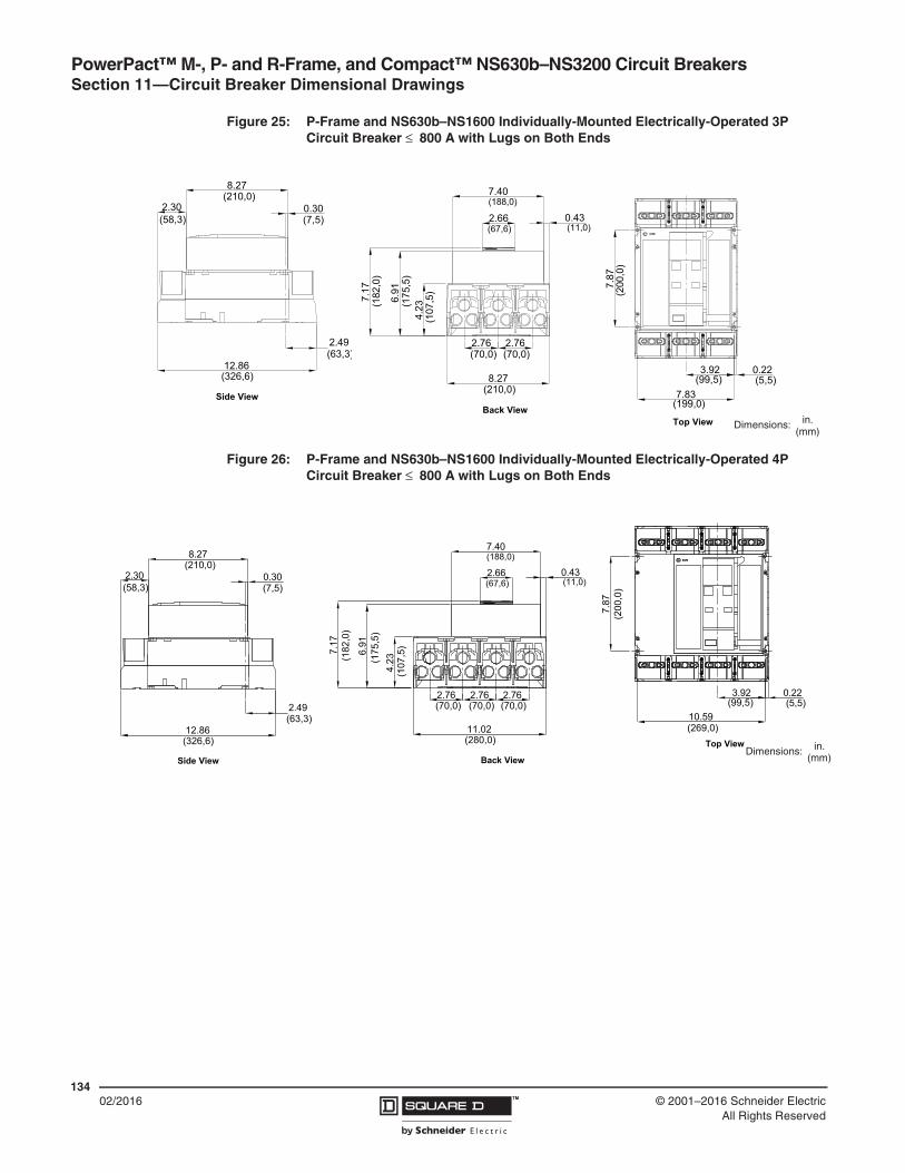
PowerPact™ M-, P- and R-Frame, and Compact™ NS630b–NS3200 Circuit Breakers Section 11—Circuit Breaker Dimensional Drawings
13402/2016 ™ © 2001–2016 Schneider Electric
All Rights Reserved
Figure 25: P-Frame and NS630b–NS1600 Individually-Mounted Electrically-Operated 3P Circuit Breaker ≤ 800 A with Lugs on Both Ends
Figure 26: P-Frame and NS630b–NS1600 Individually-Mounted Electrically-Operated 4P Circuit Breaker ≤ 800 A with Lugs on Both Ends
Side View
12.86(326,6)
(63,3)
2.30
8.27
(7,5)
(210,0)
(58,3)0.30
2.49
(11,0)(67,6)
Back View
(188,0)
8.27
2.76 2.76
4.23
(70,0) (70,0)
(210,0)6.
91(1
75,5
)
(107
,5)
7.17
(182
,0)
2.66
7.40
0.43
Top View
(5,5)
4809
6-34
8-01
3.92
7.83
0.22(99,5)
(199,0)
7.87
(200
,0)
in.(mm)
Dimensions:
Side View
12.86(326,6)
(63,3)
2.30
8.27
(7,5)
(210,0)
(58,3)0.30
2.49
(11,0)(67,6)
Back View
(188,0)
11.02
2.76 2.76
4.23
(70,0) (70,0)
(280,0)
6.91
(175
,5)
(107
,5)7.17
(182
,0)
2.66
7.40
0.43
(70,0)2.76
Top View
(5,5)
4809
6-35
6-01
3.92
10.59
0.22(99,5)
(269,0)
7.87
(200
,0)
in.(mm)
Dimensions:
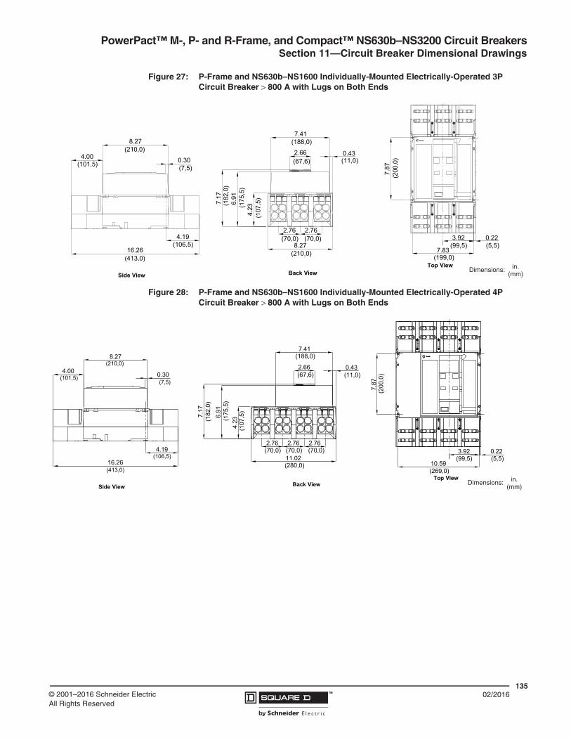
PowerPact™ M-, P- and R-Frame, and Compact™ NS630b–NS3200 Circuit BreakersSection 11—Circuit Breaker Dimensional Drawings
13502/2016™© 2001–2016 Schneider Electric
All Rights Reserved
Figure 27: P-Frame and NS630b–NS1600 Individually-Mounted Electrically-Operated 3P Circuit Breaker > 800 A with Lugs on Both Ends
Figure 28: P-Frame and NS630b–NS1600 Individually-Mounted Electrically-Operated 4P Circuit Breaker > 800 A with Lugs on Both Ends
Side View
(413,0)
(101,5)
(106,5)
(7,5)
(210,0)
4.19
16.26
0.30
8.27
4.00
7.41
2.66 0.43
(210,0)
(67,6)
Back View
7.17
6.91
4.23
(182
,0)
(188,0)
8.27
2.76 2.76(70,0) (70,0)
(175
,5)
(107
,5)
(11,0)
7.87
(199,0)7.83
3.92
Top View
0.22(99,5) (5,5)
4809
6-24
9-01
(200
,0)
in.(mm)
Dimensions:
Side View
(413,0)
(101,5)
(106,5)
(7,5)
(210,0)
4.19
16.26
0.30
8.27
4.00
7.41
2.66 0.43
(280,0)
(67,6)
Back View
7.17
6.91
4.23(1
82,0
)
(188,0)
11.02
2.76 2.76(70,0) (70,0)
(175
,5)
(107
,5)
(11,0)
2.76(70,0)
7.87
(269,0)10.59
3.92
Top View
0.22(99,5) (5,5)
4809
6-35
7-01
(200
,0)
in.(mm)
Dimensions:

PowerPact™ M-, P- and R-Frame, and Compact™ NS630b–NS3200 Circuit Breakers Section 11—Circuit Breaker Dimensional Drawings
13602/2016 ™ © 2001–2016 Schneider Electric
All Rights Reserved
Figure 29: P-Frame and NS630b–NS1600 Individually-Mounted Electrically-Operated 3P Circuit Breaker without Lugs
2.49
12.86 (63,3)(326,6)
2.30
8.27
0.30(7,5)
(210,0)
(58,3)
2.76 2.76
8.27(210,0)
(70,0) (70,0)
7.40
2.66(188,0)
(67,6)
4.23
6.91
7.17
(107
,5)
(175
,5)
(182
,0)
3.92
7.83(99,5)
(199,0)
7.87
10.1
6
(200
,0)
(258
,0)
0.370.98
1.73(44,0)
(25,0)(9,5) Ø0.43
(11,0)
A0.22(5,5)
0.59
(15,
0)
0.21
0.67
0.41
0.36
1.40(35,5)
1.14
0.72
(17,0)
(10,5)
(5,3)
(29,
0)
(9,1
)
(18,
3)
Partial View A(far side) scale1/1 Top View
Back ViewSide View
4809
6-35
2-1
in.(mm)
Dimensions:

PowerPact™ M-, P- and R-Frame, and Compact™ NS630b–NS3200 Circuit BreakersSection 11—Circuit Breaker Dimensional Drawings
13702/2016™© 2001–2016 Schneider Electric
All Rights Reserved
Figure 30: P-Frame and NS630b–NS1600 Individually-Mounted Electrically-Operated 4P Circuit Breaker without Lugs
2.49
12.86 (63,3)(326,6)
2.30
8.27
0.30(7,5)
(210,0)
(58,3)
2.76 2.76
11.02(280,0)
(70,0) (70,0)
7.40
2.66
(188,0)
(67,6)
4.23
6.91
7.17
(107
,5)
(175
,5)
(182
,0)
3.92
10.59
(99,5)
(269,0)
7.87
10.1
6
(200
,0)
(258
,0)
0.370.98
1.73(44,0)
(25,0)(9,5) Ø0.43
(11,0)
A0.22(5,5)
0.59
(15,
0)
0.21
0.67
0.41
0.36
1.40(35,5)
1.14
0.72
(17,0)
(10,5)
(5,3)
(29,
0)
(9,1
)
(18,
3)
Partial View A(far side) scale1/1
2.76(70,0)
Top View
Back ViewSide View
4809
6-35
9-01
in.(mm)
Dimensions:

PowerPact™ M-, P- and R-Frame, and Compact™ NS630b–NS3200 Circuit Breakers Section 11—Circuit Breaker Dimensional Drawings
13802/2016 ™ © 2001–2016 Schneider Electric
All Rights Reserved
Figure 31: P-Frame and NS630b–NS1600 Individually-Mounted 3P Circuit Breaker with Rotary Handle
12.86
2.49
2.11
1.86
2.30
8.27
7.68
0.30
(326,6)
(63,3)
(7,5)
(195,0)
(210,0)
(58,3)
(47,2)
(53,
5)
2.762.76
8.27(70,0)(70,0)
(210,0)
4.23
7.469.
04
(147
,0)
(175
,8)
(223
,5)
0.43
0.264.87
7.40
(11,0)
(6,5)
(123,6)
(188,0)
0.223.92
7.83(5,5)(99,5)
(199,0)
Ø0.43
Ø6.31
(11,0)
(165,0)
0.99
4.88
7.87
10.1
6
0.37
0.981.73
(9,5)
(44,0) (25,0)(25,1)
0.98(25,0)
(258
,0)
(200
,0)
(121
,5)
0.59
(15,
0)
A
1.14 0.
36
0.41
0.21
0.67
0.72
(9,1
)
(29,
0)
(35,5)
(5,3)
(10,5)
(17,0)
(18,
3)
1.40
6.32
(104
,0)
4809
6-35
1-01
Top View
Side View Back View
(far side) scale 1/1Partial View A
in.(mm)
Dimensions:

PowerPact™ M-, P- and R-Frame, and Compact™ NS630b–NS3200 Circuit BreakersSection 11—Circuit Breaker Dimensional Drawings
13902/2016™© 2001–2016 Schneider Electric
All Rights Reserved
Figure 32: P-Frame and NS630b–NS1600 Individually-Mounted 4P Circuit Breaker with Rotary Handle
Figure 33: P-Frame and NS630b–NS1600 3P Drawout Circuit Breaker Door Cutout
12.86
2.49
2.11
1.86
2.30
8.27
7.68
0.30
(326,6)
(63,3)
(7,5)
(195,0)
(210,0)
(58,3)
(47,2)
(53,
5)
2.762.76
11.02
(70,0)(70,0)
(280,0)
4.23
7.469.
04
(160
,5)
(189
,5)
(229
,5)
0.43
0.26
4.87
7.40
(11,0)
(6,5)
(123,6)
(188,0)
0.223.92
10.59(5,5)(99,5)
(269,0)
Ø0.43
Ø6.31
(11,0)
(160,2)
0.99
4.88
7.87
10.1
6
0.37
0.981.73
(9,5)
(44,0) (25,0)(25,1)
0.98(25,0)
(258
,0)
(200
,0)
(124
,1)
0.59
(15,
0)
A
1.14 0.
36
0.41
0.21
0.67
0.72
(9,1
)
(29,
0)(35,5)
(5,3)
(10,5)
(17,0)
(18,
3)
1.40
6.32
(107
,5)
(70,0)2.76
4809
6-35
8-01
Top View
Side View Back View
(far side) scale 1/1Partial View A
in.(mm)
Dimensions:
10.19(259)
11.8
8(3
02)
5.13
(130
)
12.03(306)
7.17(182)
9.02(229)
4.27
(109
)10
.15
(258
)
19.21(488)
10.15(258)
6.31(160)
10.19(259)
9.02(229)
in.(mm)
Dimensions:

PowerPact™ M-, P- and R-Frame, and Compact™ NS630b–NS3200 Circuit Breakers Section 11—Circuit Breaker Dimensional Drawings
14002/2016 ™ © 2001–2016 Schneider Electric
All Rights Reserved
Figure 34: P-Frame and NS630b–NS1600 4P Drawout Circuit Breaker Door Cutout
Figure 35: P-Frame and NS630b–NS1600 3P Drawout Circuit Breaker Rear Cutoutt
5.13
(130
)11
.88
(302
)
12.03(306)
7.17(182)
10.19(259)
11.76(299)
4.27
(109
)10
.15
(258
)
10.19(259)
10.15(258)
6.31(160)
11.76(299)
in.(mm)
Dimensions:5.
91(1
50)
1.97
(50)
0.33(9)
8.51(216)
4.61
(117
)
9.22
(234
)
8.08(205)
4.04(103)
4.29(109)
8.59(218)
in.(mm)
Dimensions:
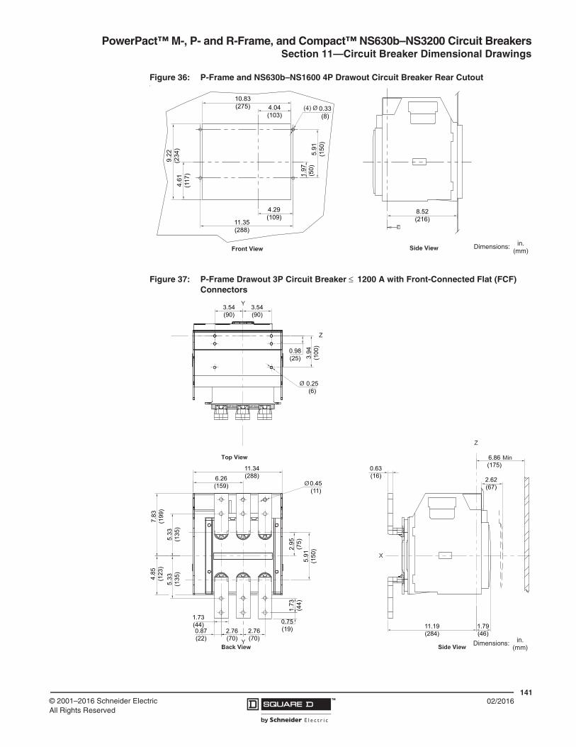
PowerPact™ M-, P- and R-Frame, and Compact™ NS630b–NS3200 Circuit BreakersSection 11—Circuit Breaker Dimensional Drawings
14102/2016™© 2001–2016 Schneider Electric
All Rights Reserved
Figure 36: P-Frame and NS630b–NS1600 4P Drawout Circuit Breaker Rear Cutoutt
Figure 37: P-Frame Drawout 3P Circuit Breaker ≤ 1200 A with Front-Connected Flat (FCF) Connectors
1.97
(50)
0.33(8)
8.52(216)
5.91
(150
)
4.61
(117
)
9.22
(234
)
4.04(103)
10.83(275)
4.29(109)
11.35(288)
in.(mm)
Dimensions:
1.79(46)
2.62(67)
6.86(175)0.63
(16)
11.19(284)
1.73
(44)
5.91
(150
)2.95
(75)
0.45(11)
0.75(19)2.76
(70)2.76(70)
6.26(159)
11.34(288)
7.83
(199
)
0.87(22)
1.73(44)
5.33
(135
)5.
33(1
35)
4.85
(123
)
3.54(90)
3.54(90)
0.98(25)
0.25(6)
3.94
(100
)
in.(mm)
Dimensions:

PowerPact™ M-, P- and R-Frame, and Compact™ NS630b–NS3200 Circuit Breakers Section 11—Circuit Breaker Dimensional Drawings
14202/2016 ™ © 2001–2016 Schneider Electric
All Rights Reserved
Figure 38: P-Frame Drawout 4P Circuit Breaker ≤ 1200 A with Front-Connected Flat (FCF) Connectors
1.79(46)
11.19(284)
9.11(231)
0.63(16)
6.86(175)
2.62(67)
0.87(22)
6.32(161)
2.76(70)
2.76(70)
7.80(198)
1.73(44)
2.76(70)
0.75(19)
1.73
(44)
5.92
(150
)2.95
(75)
5.33
(135
)
4.85
(123
)5.
33(1
35)7.
83(1
99)
0.45(11)
3.92
(100
)
3.55(90)
6.30(160)
0.98(25)
0.25(6)
in.(mm)
Dimensions:

PowerPact™ M-, P- and R-Frame, and Compact™ NS630b–NS3200 Circuit BreakersSection 11—Circuit Breaker Dimensional Drawings
14302/2016™© 2001–2016 Schneider Electric
All Rights Reserved
Figure 39: NS630b–NS1600 Drawout 3P Circuit Breaker ≤ 1600 A with Front-Connected Flat (FCF) Connectors
3.94
0.98
Ø0.33
3.543.54(90,0) (90,0)
(25,
0)
(100
,0)
(8,5)
2.76 2.76
5.55
6.73
4.84
7.83
Ø0.43
0.98
0.49
1.730.87
5.046.34
2.95
5.91
(161,0) (128,0)
(70,0) (70,0)
(22,0) (44,0)
(25,0)
(75,
0)
(150
,0)
(12,
5)
(199
,0)
(123
,0)
(141
,0)
(171
,0)
(11,0)
9.09
9.2513
.23
0.59
6.89
2.64
1.79(3
36,0
)
(15,0)
(175,0)
(67,0)
(45,5)(231,0)
(235,0)
Min
Top View
Back View
X
ZY
4809
6-36
8-01
X
Side View
Z
Y
in.(mm)
Dimensions:

PowerPact™ M-, P- and R-Frame, and Compact™ NS630b–NS3200 Circuit Breakers Section 11—Circuit Breaker Dimensional Drawings
14402/2016 ™ © 2001–2016 Schneider Electric
All Rights Reserved
Figure 40: NS630b–NS1600 Drawout 4P Circuit Breaker ≤ 1600 A with Front-Connected Flat (FCF) Connectors
3.94
6.303.54
0.98
Ø0.33
(90,0) (160,0)
(25,
0)(1
00,0
)
(8,5)
2.76 2.76 2.76
6.73
5.514.84
7.83
2.95
5.91
0.49
0.98
1.730.87
6.34 7.80
(70,0) (70,0) (70,0)
(22,0)(25,0)
(44,0)
(161,0) (198,0)
(123
,0)
(199
,0)
(171
,0)
(140
,0)
(12,
5)
Ø0.43
(11,0)
(25,
0)
(100
,0)
9.09
9.25
0.59
13.2
31.79
6.89
2.64
(175,0)
(15,0)
(231,0)
(235,0) (45,5)
(67,0)
(336
,0)
MinTop View
Back View
X
Z
Y
4809
6-37
1-01
Z
X
Side View
Y
in.(mm)
Dimensions:

PowerPact™ M-, P- and R-Frame, and Compact™ NS630b–NS3200 Circuit BreakersSection 11—Circuit Breaker Dimensional Drawings
14502/2016™© 2001–2016 Schneider Electric
All Rights Reserved
Figure 41: P-Frame Drawout 3P Circuit Breaker ≤ 1200 A with Rear-Connected “T” Vertical (RCTV) Connectors
1.73(44)
6.86(175)
2.62(67)
12.67(322)
1.79(46)
9.11(231)
2.95
(75)
1.73
(44)
5.91
(150
)
0.87(22)
0.75(19)
0.45(11)
4.85
(123
)
3.54(90)
3.54(90)
2.76(70)
2.76(70)
5.06(128)
6.32(161)
7.83
(199
)
0.98(25)
3.54(90)
3.54(90)
0.25(6)
0.37(10)
3.94
(100
)
in.(mm)
Dimensions:

PowerPact™ M-, P- and R-Frame, and Compact™ NS630b–NS3200 Circuit Breakers Section 11—Circuit Breaker Dimensional Drawings
14602/2016 ™ © 2001–2016 Schneider Electric
All Rights Reserved
Figure 42: P-Frame Drawout 4P Circuit Breaker ≤ 1200 A with Rear-Connected “T” Vertical (RCTV) Connectors
1.73(44)
12.67(322)
9.11(231)
1.79(46)
2.62(67)
6.86(175)
8.99
(228
)
0.75(19)
1.73(44)
0.87(22)
4.50
(114
)
0.45(11)
2.76(70)
2.76(70)
6.32(161)
7.80(198)
2.76(70)
0.37(10)
5.91
(150
)
4.85
(123
)7.
83(1
99)
0.98(25)
6.30(160)
3.54(90)
0.25(6)
3.92
(100
)
in.(mm)
Dimensions:

PowerPact™ M-, P- and R-Frame, and Compact™ NS630b–NS3200 Circuit BreakersSection 11—Circuit Breaker Dimensional Drawings
14702/2016™© 2001–2016 Schneider Electric
All Rights Reserved
Figure 43: NS630b–NS1600 Drawout 3P Circuit Breaker ≤ 1600 A with Rear-Connected “T” Vertical (RCTV) Connectors
3.543.54
0.98
3.94
Ø0.33
0.59
(90,0) (90,0)
(15,0)
(25,
0)(1
00,0
)
(8,5)
4.84
5.91
6.34 5.04
2.76 2.76
(123
,0) (1
50,0
)
(70,0) (70,0)
(161,0) (128,0)9.09
10.551.81
2.64
6.89
0.98
1.73
0.87
0.51
0.51
1.97
Ø0.43
(175,0)
(67,0)(50,0)
(13,0)
(231,0)(46,0)
(268,0)
(11,0) (22,
0)
(25,
0)
(44,
0)
(13,0)
MinTop View
Side View
X
Z
4809
6-36
6-01 Y
Z
Back View
8.98
(228
,0) 4.
49(1
14,0
)
in.(mm)
Dimensions:

PowerPact™ M-, P- and R-Frame, and Compact™ NS630b–NS3200 Circuit Breakers Section 11—Circuit Breaker Dimensional Drawings
14802/2016 ™ © 2001–2016 Schneider Electric
All Rights Reserved
Figure 44: NS630b–NS1600 Drawout 4P Circuit Breaker ≤ 1600 A with Rear-Connected “T” Vertical (RCTV) Connectors
3.94
0.98
6.303.54
Ø0.33
0.59
(90,0) (160,0)
(15,0)
(25,
0)
(100
,0)
(8,5)
2.76 2.76 2.76
5.91
4.84
7.83
6.34 7.80
(150
,0)
(199
,0)
(123
,0)
(70,0) (70,0) (70,0)
(161,0) (198,0) 0.98
1.73
0.87
0.49
1.93
8.98
4.49
10.53
9.09
1.79
2.64
6.89(175,0)
(67,0)(49,0)
(12,5)
(231,0)
(267,0) (45,5)
(228
,0)
(114
,0)
(44,
0)
(25,
0)
(22,
0)
Min
Ø0.43(11,0)
Top View
Back View
X
Z
Y
4809
6-36
9-01
X
Y
Side View
Z
in.(mm)
Dimensions:

PowerPact™ M-, P- and R-Frame, and Compact™ NS630b–NS3200 Circuit BreakersSection 11—Circuit Breaker Dimensional Drawings
14902/2016™© 2001–2016 Schneider Electric
All Rights Reserved
Figure 45: P-Frame Drawout 3P Circuit Breaker ≤ 1200 A with Rear-Connected “T” Horizontal (RCTH) Connectors
4.48
(114
,0)
8.90
(228
,0)
3.56(90)
9.11(231)
12.64(321)
0.37(10)
6.86(175)
2.62(67)
1.79(46)
5.91
(150
)2.95
(75)
5.06(128)
6.32(161)
2.76(70)
2.76(70)
7.83
(199
)4.
85(1
23)
0.45(11)
3.54(90)
3.54(90)
1.73(44)
0.98(25)
0.25(6)
0.75(19)
0.87(22)
3.94
(100
)
1.73
(44)
in.(mm)
Dimensions:

PowerPact™ M-, P- and R-Frame, and Compact™ NS630b–NS3200 Circuit Breakers Section 11—Circuit Breaker Dimensional Drawings
15002/2016 ™ © 2001–2016 Schneider Electric
All Rights Reserved
Figure 46: P-Frame Drawout 4P Circuit Breaker ≤ 1200 A with Rear-Connected “T” Horizontal (RCTH) Connectors
0.37(10)
6.86(175)
2.62(67)
12.67(322)
9.11(231)
1.79(46)
4.50
(114
)
8.99
(228
,0)
2.76(70)
2.76(70)
2.76(70)
7.80(198)
6.32(161)
4.85
(123
)7.
83(1
99)
5.92
(150
)296
(75)
1.73(44)
0.87(22)
0.75(19)
0.98(25)
0.25(6)
6.30(160)
3.54(90)
0.45(11)
3.92
(100
)
1.73
(44)
in.(mm)
Dimensions:

PowerPact™ M-, P- and R-Frame, and Compact™ NS630b–NS3200 Circuit BreakersSection 11—Circuit Breaker Dimensional Drawings
15102/2016™© 2001–2016 Schneider Electric
All Rights Reserved
Figure 47: NS630b–NS1600 Drawout 3P Circuit Breaker ≤ 1600 A with Rear-Connected “T” Horizontal (RCTH) Connectors
3.94
0.98
3.543.54
0.98
0.51
0.871.73
Ø0.43
(90,0) (90,0)
(25,0)(22,0)
(44,0)(11,0)
(25,
0)
(100
,0)
(13,
0)
Ø0.33(8,5)
4.84
7.83
2.95
5.91
6.34 5.04
2.76 2.76
(75,
0)
(150
,0)
(199
,0)
(123
,0)
(161,0) (128,0)
(70,0) (70,0) 9.09
10.55
1.794.
49
8.98
0.59
1.93 2.64
6.89 Min
(67,0)(49,0)
(231,0)
(268,0)
(45,5)
(228
,0)
(15,
0)(1
14,0
)
(175,0)Top View
Back View Side View
X
Z
Y
4809
6-36
7-01
X
Z
in.(mm)
Dimensions:

PowerPact™ M-, P- and R-Frame, and Compact™ NS630b–NS3200 Circuit Breakers Section 11—Circuit Breaker Dimensional Drawings
15202/2016 ™ © 2001–2016 Schneider Electric
All Rights Reserved
Figure 48: NS630b–NS1600 Drawout 4P Circuit Breaker ≤ 1600 A with Rear-Connected “T” Horizontal (RCTH) Connectors
Figure 49: P-Frame and NS630b–NS1600 100–1600 A External Neutral Current Transformers
3.94
0.98
6.303.54
Ø0.330.
49
0.87 0.98
1.73
Ø0.43
(90,0) (160,0)
(22,0) (25,0)
(44,0)
(12,
5)
(25,
0)
(100
,0)
(8,5)
(11,0)
2.762.762.76
4.84
7.83
6.34 7.80
2.95
5.91
(70,0) (70,0) (70,0)
(161,0) (198,0)
(123
,0)
(199
,0)
(75,
0)
(150
,0)
8.98
9.09
10.53
0.59
4.49
1.93 2.64
6.89
1.79
(228
,0)
(15,
0)
(49,0)
(175,0)
(67,0)
(231,0)
(267,5) (45,5)
(114
,0)
Min
Top View
Back View Side View
X
Z
Y
4809
6-37
0-01
X
Z
in.(mm)
Dimensions:
1.38(34,9)
0.56(14,2)
0.62(15,7)
8.20(208,3)
6.95(176,5) 0.94
(23,7)
3.00(76,2)
5.04(127,9)
5.38(136,7)
in.(mm)
Dimensions:

PowerPact™ M-, P- and R-Frame, and Compact™ NS630b–NS3200 Circuit BreakersSection 11—Circuit Breaker Dimensional Drawings
15302/2016™© 2001–2016 Schneider Electric
All Rights Reserved
Dimensions for R-Frame and NS1600b–NS3200 Circuit Breakers
Figure 50: R-Frame Individually-Mounted UL Listed 3P Circuit Breaker
Circuit Breaker 1600 A2000 A2500 A3000 A
"A"0.50 in. (12.8 mm)0.63 in. (16 mm)0.79 in. (20 mm)0.79 in. (20 mm)
See
Tab
le
(210,0)
(248
,8)
(12,6)(113,0)
(6,0)
(7,5)
(30,0)
(11,0)
(6,9)
(139,6)(339,8)
(163,0)
(38,6)
(119
,3)
(18,
3)
(131
,8)
(168
,5)
(222
,3)(3
68,0
)
(15,
9)(1
50,0
)(1
15,5
)
(381
,1)
(44,
5)
(115,0)
(11,0)
(15,8)
(44,5)(115,0)
(22,3)
(390,0)
(14,5
(195,0) (15,0)(76,0)
in.(mm)
Dimensions:
Minimum Enclosure Size30 x 21 x 7(762 x 533 x 178)
Minimum Ventilation (100% Rated Circuit Breakers Only):40.25 in.2 (250 cm2) on top and bottom of enclosure

PowerPact™ M-, P- and R-Frame, and Compact™ NS630b–NS3200 Circuit Breakers Section 11—Circuit Breaker Dimensional Drawings
15402/2016 ™ © 2001–2016 Schneider Electric
All Rights Reserved
Figure 51: R-Frame Individually-Mounted UL Listed 4P Circuit Breaker
1.52(38,6)
0.24(6,0)
0.30(7,5)
1.18(30,0) 25 Off
28 On
4 Tripped
9.79
(248
,8)
4.45(113,0)
8.27(210,0)
0.49(12,6)
5.19
(131
,8)
6.63
(168
,5)
8.75
(222
,3)
Han
dle
Ext
ende
dH
andl
eFo
lded
14.4
9(3
68,0
)
At Max
At Max
R6.42HandleFolded(163,0)
5.50(139,6)
13.38(339,8)
0.43
0.27
(11,0)
(6,9)
7.68(195,0)19.88
(505,0)
0.59(15,0)
Ø0.43(11,0)
5.91
(150
,0)
See
Tab
le
"A"
(119
,3)
4.70
(18,
3).7
2
0.62(15.7)
4.53(115.0)
4.53(115.0)
15.0
0(3
81.1
)
4.55
(115
.5)
4.53(115.0)
0.62
(15.
8)
0.88(22.2)
1.75
(44.
5)
Ø0.57
(Ø14.5)
1.75(44.5)
2.99 (76.0)
4809
6-45
0-01
Top View
Back ViewSide View
Circuit Breaker "A"1600 A 0.50 in. (12.8 mm)2000 A 0.63 in. (16.0 mm)2500 A 0.79 in. (20.0 mm)3000 A 0.79 in. (20.0 mm)
in.(mm)
Dimensions:

PowerPact™ M-, P- and R-Frame, and Compact™ NS630b–NS3200 Circuit BreakersSection 11—Circuit Breaker Dimensional Drawings
15502/2016™© 2001–2016 Schneider Electric
All Rights Reserved
Figure 52: NS1600b–NS3200 Individually-Mounted IEC Rated, 3P Circuit Breaker0.
72
4.70
(18,
3)
(119
,3)
0.24(6,0)
0.30(7,5)
1.18(30,0)
4° Tripped
25° Off
4.45(113,0)
1.52(38,6)
0.79
(20,
0)9.
79(2
48,8
)
0.49
8.27(210,0)
(12,6)
28° On5.
19(1
31,8
)
6.63
(168
,5)
8.75
(222
,3)
14.4
9(3
68,0
)
R 6.42(163,0)
HandleFolded
5.50(139,6)
13.38(339,8)
0.43(11,0)
0.27(6,9)H
andl
eE
xten
ded
Han
dle
Fold
ed
At Max
At Max
0.59(15,0)
7.68(195,0)
15.35(390,0)
Ø0.43(11,0)
Ø0.49(12,5)
0.512.99
(13,0)(76,0)
0.98
1.97(50,0)
(25,0)
0.59
(15,
0)2.
95(7
5,0)
5.91
(150
,0)
11.8
1(3
00,0
)
4.534.53(115,0)(115,0)
4809
6-20
9-01
Top View
Back ViewSide Viewin.
(mm)Dimensions:

PowerPact™ M-, P- and R-Frame, and Compact™ NS630b–NS3200 Circuit Breakers Section 11—Circuit Breaker Dimensional Drawings
15602/2016 ™ © 2001–2016 Schneider Electric
All Rights Reserved
Figure 53: NS1600b–NS3200 Individually-Mounted IEC Rated 4P Circuit Breaker
1.52
0.79
.72
4.70
(38,6)
(119
,3)
(18,
3) (20,
0)
0.24(6,0)
0.30(7,5)
1.18(30,0) 25° Off
28° On
4° Tripped
9.79
(248
,8)
4.45(113,0)
8.27(210,0)
0.49(12,6)
5.19
(131
,8)
6.63
(168
,5)
8.75
(222
,3)
Han
dle
Ext
ende
dH
andl
eFo
lded
14.4
9(3
68,0
)
At Max
At Max
R6.42HandleFolded(163,0)
5.50(139,6)
13.38(339,8)
0.43
0.27
(11,0)
(6,9)
4.534.53 4.53(115,0) (115,0) (115,0)
7.68(195,0)19.88
(505,0)
0.59(15,0)
Ø0.49(12,5)
Ø0.43(11,0)
0.51(13,0)
2.99(76,0)0.98
1.97
(25,0)
(50,0)
0.59
(15,
0)2.
95(7
5,0)
5.91
(150
,0)
11.8
1(3
00,0
)
4809
6-24
5-01
Top View
Back ViewSide View
in.(mm)
Dimensions:

PowerPact™ M-, P- and R-Frame, and Compact™ NS630b–NS3200 Circuit BreakersSection 11—Circuit Breaker Dimensional Drawings
15702/2016™© 2001–2016 Schneider Electric
All Rights Reserved
Figure 54: R-Frame RLTB 3P Terminal Pad (UL)
0.79
(20,
0)
9.40
(238
,9)
18.1
6(4
61,2
)
2.50(63,5)
5.00(127,0)
7.05(178,9)
3.50(88,9)
4.53(115,0)
3.50 4.53 3.50(88,9) (115,0) (88,9)20.99(533,2)
0.72(18,3)
2.11(53,6)
4.53
(115
,0)
5.91
(150
,0)
4.55
(115
,5)
0.62
(15,
9)
15.35(390,0)
Side View Back View
Top View
in.(mm)
Dimensions:

PowerPact™ M-, P- and R-Frame, and Compact™ NS630b–NS3200 Circuit Breakers Section 11—Circuit Breaker Dimensional Drawings
15802/2016 ™ © 2001–2016 Schneider Electric
All Rights Reserved
Figure 55: R-Frame RL3TB 3P Terminal Pad (UL)
18.1
6(4
61,2
)
0.79
(20,
0)
9.40
(238
,9)
10.05(255,3)
4.00(101,8)
8.00(127,0)
3.50(55,9)
1.06(26,92)
3.50(88,9)
4.53(115,0)
21.67(550,4)
4.53(115,0)
3.50(88,90)
0.62
(15,
9)
4.55
(115
,5)
6.03
(153
,1)
5.91
(150
,0)
15.35(390,0)
2.11(53,6)
in.(mm)
Dimensions:

PowerPact™ M-, P- and R-Frame, and Compact™ NS630b–NS3200 Circuit BreakersSection 11—Circuit Breaker Dimensional Drawings
15902/2016™© 2001–2016 Schneider Electric
All Rights Reserved
Figure 56: R-Frame RLTB 4P Terminal Pad (UL)
0.79
(20,
0)
9.40
(238
,9)
18.1
6(4
61,2
)
2.50(63,5)
5.00(127,0)
7.05(178,9)
3.50(88,9)
4.53(115,0)
3.50 4.53 3.50(88,9) (115,0) (88,9)
29.02(737,1)
0.72(18,3)
2.11(53,6)
4.53
(115
,0)
5.91
(150
,0)
4.55
(115
,5)
0.62
(15,
9)
19.88(505,0)
4.533.50(88,9) (115,0)
Side View Back View
Top View
in.(mm)
Dimensions:

PowerPact™ M-, P- and R-Frame, and Compact™ NS630b–NS3200 Circuit Breakers Section 11—Circuit Breaker Dimensional Drawings
16002/2016 ™ © 2001–2016 Schneider Electric
All Rights Reserved
Figure 57: R-Frame RL3TB 4P Terminal Pad (UL)
3.50(88,9)
4.53(115,0)
1.06(26,92)
3.50(88,9)
4.53(115,0)
3.50(88,9)
29.70(754,38)
4.53(115,0)
3.50(88,9)
0.79
(20,
0) 18.1
6(4
61,2
)
9.40
(238
,9)
10.05(255,3)
8.00(127,0)
4.00(101,6)
6.03
(153
,1)
4.55
(115
,5)
0.62
(15,
8)5.
91(1
50,0
)
19.88(505,0)
2.11(53,6)
18.0
(457
,33)
in.(mm)
Dimensions:

PowerPact™ M-, P- and R-Frame, and Compact™ NS630b–NS3200 Circuit BreakersSection 11—Circuit Breaker Dimensional Drawings
16102/2016™© 2001–2016 Schneider Electric
All Rights Reserved
Figure 58: NS1600b–NS3200 RLTBE Terminal Pad (IEC)
0.72
1.05
2.46
0.49
0.98
1.972.95
3.94
(12,5)
(25,0)
(50,0)(75,0)
(100,0)
(62,5)
(26,
7)(1
8,3)
10.3
9(2
64,0
)
4.53
6.10 4.53
0.39
0.39
(115,0)(155,0)
(115,0)
(10,0)
(10,0)
TYP
TYP
(13,0)(25,0)
(50,0)
3.152.17 (80,0)
(55,0)(35,
0)1.
38
4.92
5.91
(150
,0)
(125
,0)
2.95
0.59
(75,
0)(1
5,0)
19.88(505,0)
M 10
0.510.98
1.9715.35(390,0)
4 Pole
3 Pole
Side View
Top View
Back View
in.(mm)
Dimensions:

PowerPact™ M-, P- and R-Frame, and Compact™ NS630b–NS3200 Circuit Breakers Section 11—Circuit Breaker Dimensional Drawings
16202/2016 ™ © 2001–2016 Schneider Electric
All Rights Reserved
Figure 59: R-Frame and NS1600b–NS3200 Enclosure Mounting Holes and Door Cutouts
Figure 60: R-Frame and NS1600b–NS3200 100–1600 A External Neutral Current Transformers
Ø0.43(11,0)
15.35 3-pole
19.88(505,0) 4-pole4x
5.91
15.35(390,0) 3-pole
19.88(505,0) 4-poleØ0.43
(11,0)4x
Ø0.43(11,0)
15.35(390,0) 3-pole
4x
5.91
13.62 0.87
8.50
1.30
2.30
10.5
1
15.630.14
(346,0) (22,0)
(33,0)
(216
,0)
(150
,0)
(390,0)
(58,5)
(3,5)(397,0)
(267
,0)
(150
,0)
5.75 4.800.80
4.69
5.91
(146,0) (122,0)(20,4)
(119
,0)
(150
,0)
Accessory Cover Cutout
Handle Cutout
Accessory Cover Escutcheon Cutout
in.(mm)
Dimensions:
6.39
(162
)
4.92(125)
2.00(51)
0.75(19)
3.00
(76)
8.10(206)
6.85(174)
0.56(14)
1.75
(44)
in.(mm)
Dimensions:
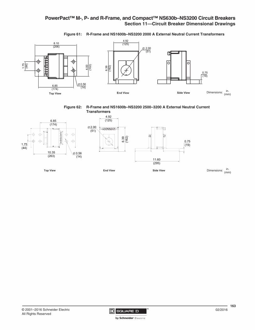
PowerPact™ M-, P- and R-Frame, and Compact™ NS630b–NS3200 Circuit BreakersSection 11—Circuit Breaker Dimensional Drawings
16302/2016™© 2001–2016 Schneider Electric
All Rights Reserved
Figure 61: R-Frame and NS1600b–NS3200 2000 A External Neutral Current Transformers
Figure 62: R-Frame and NS1600b–NS3200 2500–3200 A External Neutral Current Transformers
8.10(206)
6.39
(162
)
4.00
(102
)
1.75
(44)
6.85(174)
0.56(14)
0.75(19)
2.00(51)
4.92(125)
in.(mm)
Dimensions:
0.56(14)
4.92(125)
2.00(51)
10.35(263)
1.75(44)
6.85(174)
6.39
(162
)
0.75(19)
11.60(295)
in.(mm)
Dimensions:

PowerPact™ M-, P- and R-Frame, and Compact™ NS630b–NS3200 Circuit Breakers
16402/2016 ™ © 2001–2016 Schneider Electric
All Rights Reserved
Section 12—Accessory Dimensional Drawings
Accessory Dimensions
Figure 63: IFE Ethernet Interface
Figure 64: I/O (Input/Output) Application Module
ETH1 ETH2
Modbus-SL
LV434011
ETH1 LK/10-100/ACT
ETH2 LK/10-100/ACT
Module Status
Network Status
R
IFEIFE-XX.YY.ZZ (factory set)
Modbus-SL
LV434011
ETH1 LK/10-100/ACT
ETH2 LK/10-100/ACT
Module Status
Network Status
IFEIFE-XX.YY.ZZ (factory set)
T
2.83(72)
2.80(71)
2.50(63,6)
1.77(45)
3.34(84,8)
3.62(92) 4.13
(105)
Dimensions:in.
(mm)
13O1 O2 O3 A1
14 23 24 33 34 T1 T2
I1 A1
O1O2O3
I2I3I4I5I6
I1 A1
O1O2O3
I2I3I4I5I6
I1 I2 I3 I4 I5 I6C C C24VDC
LV434063IO
2.83(72)
3.62(92)
2.50(63,6)
1.77(45)
3.34(84,8)
4.53(115)
2.80(71)
Dimensions: in.(mm)

PowerPact™ M-, P- and R-Frame, and Compact™ NS630b–NS3200 Circuit Breakers
16502/2016™© 2001–2016 Schneider Electric
All Rights Reserved
Figure 65: IFM Modbus-SL Interface
Figure 66: FDM121 Switchboard Display Dimensions
Figure 67: FDM121 Switchboard Display Mounting Through Panel
0.71(18)
3.62(92)
1.77(45)
3.35(85)
4.13(105)
2.60(66)2.87(73)
Dimensions: in.(mm)
3.78(96)
Y
X
3.78(96)
Dimensions: in.(mm)
X
Z
Y
X
0.81(20,7)
0.42(10,6)
0.91(23)
3.62+0.03/-0
(92+0.8/-0)
3.62+0.03/-0
(92+0.8/-0)
Dimensions: in.(mm)

PowerPact™ M-, P- and R-Frame, and Compact™ NS630b–NS3200 Circuit Breakers
16602/2016 ™ © 2001–2016 Schneider Electric
All Rights Reserved
Figure 68: FDM121 Switchboard Display Mounting On Panel
Figure 69: FDM128 Switchboard Display Dimensions
Z
X
0.59(15)
1.46(37)
Y
X
99.3
2 Ø
2 Ø
0.75(19)
1.26+/-0.02
(32+/-0.5)
3.91(99,3)
0.65(16,5)
0.89(22,5)
0.51(13)
0.67(17)
0.79(20)
1.30(99.3)
3.91+/-0.06 (33+/-1.5)
0.23+/-0.01 (22,5+/-0,3)
Dimensions: in.(mm)
X
Y
5.08(129)
6.42(163)
Dimensions:in.
(mm)

PowerPact™ M-, P- and R-Frame, and Compact™ NS630b–NS3200 Circuit Breakers
16702/2016™© 2001–2016 Schneider Electric
All Rights Reserved
Figure 70: FDM128 Switchboard Display Mounting on Panel
X
(1.5–6)
1.54(39)
0.69(17.5)
1.20(30.6)
3.94(100)
3.94(100)
3.94(100)
3.94(100)
3.94(100)
Ø
X
Y
0.89+0/-0.01
(22,4+0/-0,30)
1.18+0/-0.008
(30+0/-0,20)
Dimensions: in.(mm)

PowerPact™ M-, P- and R-Frame, and Compact™ NS630b–NS3200 Circuit Breakers
16802/2016 ™ © 2001–2016 Schneider Electric
All Rights Reserved
Figure 71: Masterpact, PowerPact, and Compact Circuit Breaker Communication
A. FDM121 (TRV00121) E. IO application module (LV434063) I. ULP termination (TRV00880)
J. FDM128 (LV434128)B. IFE master (LV434011)
C. IFE (LV434010)
D. IFM (TRV00210)
F. Masterpact NT/NW
G. PowerPact P/R
H. PowerPact H/J/L
I
H H
13O1
I1I2
I5I6
C
C
1423 24
T1 T2
O2
A1
IO ModuleIO Module
+24VDC
I1I2 I3
I4 I5I6
C
C
C
13O1
I1I2
I3
I5I6
C
C
1423 24
T1 T2
O2
A1
+24VDC
I1I2 I3
I6
C
C
13O1
I1
A1
O1O2O3
I2I3
I4I5
I6
C
C
C
1423 24
33 34T1 T2
O2
O3
A1
IO Module
A1
O1O2O3
IO Module
+24VDC
I1I2 I3
I4 I5I6
C
C
C
E I4C
Eth1
Eth2
+24V0V
Modbus
II
M
ML L
KK
K
K
K
G
B
Eth1
Eth2
+24V0V
C
D
I
A
I
A
I
A
F
Eth1
Eth2
+24V0V
C
24 V DC
24 V DC
24 V DC
FL
J
K. ULP cable
L. Circuit breaker ULP cord
M. NSX cord
Ethernet
A A A
I
K
C
CK I
E
I
D
I
II
K
KK
E
FL
F
L L
GH
M
M
H
K
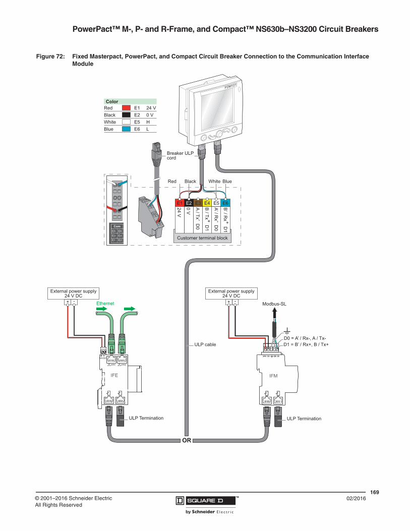
PowerPact™ M-, P- and R-Frame, and Compact™ NS630b–NS3200 Circuit Breakers
16902/2016™© 2001–2016 Schneider Electric
All Rights Reserved
Figure 72: Fixed Masterpact, PowerPact, and Compact Circuit Breaker Connection to the Communication Interface Module
IFM
Modbus-SL
OR
+ -
D0 = A’ / Rx-, A / Tx-D1 = B’ / Rx+, B / Tx+
ULP Termination
External power supply24 V DC
External power supply24 V DC
ETH1 ETH2
24VDC
+ -
IFE
Ethernet
ULP Termination
B’ / R
x + D1
A’ / Rx - D
0
B / Tx + D
1
A / Tx - D0
0 V
24 V
E1
Red
Breaker ULP cord
ULP cable
Black Blue
E2 E3 E4 E5 E6
Customer terminal block
White
ColorRed E1Black E2White E5Blue E6
24 V0 VHL
FDM121

PowerPact™ M-, P- and R-Frame, and Compact™ NS630b–NS3200 Circuit Breakers
17002/2016 ™ © 2001–2016 Schneider Electric
All Rights Reserved
Figure 73: Drawout Masterpact, PowerPact, and Compact Circuit Breaker Connection to the I/O and Communication Interface Module
24VDC
IO application moduleColor
Red E1Black E2White E5Blue E6
24 V0 VHL
B’ / R
x + D1
A’ / Rx - D
0
B / Tx + D
1
A / Tx - D0
0 V
24 V
E1
Red Black Blue
E2 E3 E4 E5 E6
White
Breaker ULP cord
Customer terminal block
ETH1 ETH2
24VDC
IFM IFE
EthernetModbus-SL
24 V DC24 V DC
OR
ULP cable
ULP Termination ULP Termination
FDM121

PowerPact™ M-, P- and R-Frame, and Compact™ NS630b–NS3200 Circuit BreakersSection 13—Trip Curves
17102/2016™© 2001–2016 Schneider Electric
All Rights Reserved
Section 13—Trip Curves
Basic Electronic Trip Unit ET 1.0I, M-Frame 800 A Characteristic Trip Curve
1.51
1
MULTIPLES OF SENSOR RATING (In)
MULTIPLES OF SENSOR RATING (In)
.5 .6 .7 .8 .9 1.5
2 3 4 5 6 7 8 9 10 15 20 30 40 50 60 70 80 90 100
.5 .6 .7 .8 .9 2 3 4 5 6 7 8 9 10 15 20 30 40 50 60 70 80 90 100
200
300
400
500
600
700
8009001000
1500
2000
3000
4000
6000
7000
80009000
5000
10000
.005
.006
.007
.008
.009.01
.015
.02
.03
.04
.05
.06
.07
.08
.09.1
.005
.006
.007
.008
.009
.01
.015
.02
.03
.04
.05
.06
.07
.08
.09
.1
.15
.2
.3
.4
.5
.6
.7
.8
.91
.15
.2
.3
.4
.5
.6
.7
.8
.91
1.5
2
3
4
5
6
7
89
10
1.5
2
3
4
5
6
7
8910
15
20
30
40
50
60
70
8090
100
15
20
30
40
50
60
70
8090100
150
200
300
400
500
600
700
800900
1000
1500
2000
3000
4000
5000
6000
7000
80009000
10000T
IME
IN S
EC
ON
DS
CYCLE21
1 CYCLE
150
2 x 3 x 4 x 6 x 8 x 10 x
5 x
INSTANTANEOUSPICKUP
x In
ELECTRONIC TRIP 1.0CHARACTERISTIC TRIP CURVE NO. 613-14
Long-time Pickup and DelayInstantaneous Pickup and Delay
2x–10x
The time-current curve information is to be usedfor application and coordination purposes only.
Curves apply from -25°C to +70°C (-13°F to +158°F) ambient temperature.
Instantaneous override values are given on 613-10.
Notes:
1. There is a thermal-imaging effect that can actto shorten the long-time delay. The thermal-imaging effect comes into play if a currentabove the long-time delay pickup value existsfor a time and then is cleared by the tripping ofa downstream device or the circuit breakeritself. A subsequent overload will cause thecircuit breaker to trip in a shorter time thannormal. The amount of time delay reduction isinverse to the amount of time that has elapsedsince the previous overload. Approximately 20minutes is required between overloads tocompletely reset thermal-imaging.
2. Total clearing times shown include theresponse times of the trip unit, the circuitbreaker opening, and the extinction of thecurrent.

PowerPact™ M-, P- and R-Frame, and Compact™ NS630b–NS3200 Circuit Breakers Section 13—Trip Curves
17202/2016 ™ © 2001–2016 Schneider Electric
All Rights Reserved
Basic Electronic Trip Unit 1.0I P- and R-Frame Characteristic Trip Curve
1.51
1
MULTIPLES OF SENSOR RATING (In)
MULTIPLES OF SENSOR RATING (In)
.5 .6 .7 .8 .9 1.5
2 3 4 5 6 7 8 9 10 15 20 30 40 50 60 70 80 90 100
.5 .6 .7 .8 .9 2 3 4 5 6 7 8 9 10 15 20 30 40 50 60 70 80 90 100
200
300
400
500
600
700
8009001000
1500
2000
3000
4000
6000
7000
80009000
5000
10000
.005
.006
.007
.008
.009.01
.015
.02
.03
.04
.05
.06
.07
.08
.09.1
.005
.006
.007
.008
.009
.01
.015
.02
.03
.04
.05
.06
.07
.08
.09
.1
.15
.2
.3
.4
.5
.6
.7
.8
.91
.15
.2
.3
.4
.5
.6
.7
.8
.91
1.5
2
3
4
5
6
7
89
10
1.5
2
3
4
5
6
7
8910
15
20
30
40
50
60
70
8090
100
15
20
30
40
50
60
70
8090100
150
200
300
400
500
600
700
800900
1000
1500
2000
3000
4000
5000
6000
7000
80009000
10000
TIM
E IN
SE
CO
ND
S
CYCLE21
1 CYCLE
150
1.5 x
INSTANTANEOUSPICKUP
x In
LONG-TIMEPICKUP
LONG-TIMEDELAY
5 x
10 x
2 x 3 x 4 x 6 x 8 x 12 x
ELECTRONIC TRIP 1.0ICHARACTERISTIC TRIP CURVE NO. 613-12
Long-time Pickup and Fixed DelayInstantaneous Pickup
1.5x-12x
The time-current curve information is to be usedfor application and coordination purposes only.
Curves apply from -25°C to +70°C (-13°F to +158°F) ambient temperature.
Instantaneous override values are given on 613-10.
Notes:
1. There is a thermal-imaging effect that can actto shorten the long-time delay. The thermal-imaging effect comes into play if a currentabove the long-time delay pickup value existsfor a time and then is cleared by the tripping ofa downstream device or the circuit breakeritself. A subsequent overload will cause thecircuit breaker to trip in a shorter time thannormal. The amount of time delay reduction isinverse to the amount of time that has elapsedsince the previous overload. Approximately 20minutes is required between overloads tocompletely reset thermal-imaging.
2. Total clearing times shown include theresponse times of the trip unit, the circuitbreaker opening, and the extinction of thecurrent.

PowerPact™ M-, P- and R-Frame, and Compact™ NS630b–NS3200 Circuit BreakersSection 13—Trip Curves
17302/2016™© 2001–2016 Schneider Electric
All Rights Reserved
Micrologic 2.0A NS630b–NS3200 Trip Unit Characteristic Trip Curve
1.51
1
CURRENT IN MULTIPLES OF Ir (Ir = LONG-TIME SETTING x In)
CURRENT IN MULTIPLES OF Ir (Ir = LONG-TIME SETTING x In)
.5 .6 .7 .8 .9 1.5
2 3 4 5 6 7 8 9 10 15 20 30 40 50 60 70 80 90 100
.5 .6 .7 .8 .9 2 3 4 5 6 7 8 9 10 15 20 30 40 50 60 70 80 90 100
200
300
400
500
600
700
8009001000
1500
2000
3000
4000
6000
7000
80009000
5000
10000
.005
.006
.007
.008
.009.01
.015
.02
.03
.04
.05
.06
.07
.08
.09.1
.005
.006
.007
.008
.009
.01
.015
.02
.03
.04
.05
.06
.07
.08
.09
.1
.15
.2
.3
.4
.5
.6
.7
.8
.91
.15
.2
.3
.4
.5
.6
.7
.8
.91
1.5
2
3
4
5
6
7
89
10
1.5
2
3
4
5
6
7
8910
15
20
30
40
50
60
70
8090
100
15
20
30
40
50
60
70
8090100
150
200
300
400
500
600
700
800900
1000
1500
2000
3000
4000
5000
6000
7000
80009000
10000
TIM
E IN
SE
CO
ND
S
CYCLE21
1 CYCLE
150
24
20
.5
16
128
2.51.5 2
4
3 5
6
8
10
4
2
1
16
LONG-TIME PICKUPx In = Ir
LONG-TIMEDELAY BANDS
SECONDS AT 6 x Ir
SHORT-TIMEPICKUP
x Ir
24
MICROLOGIC® 2.0 A TRIP UNITCHARACTERISTIC TRIP CURVE NO. 613-9
Long-time Pickup and DelayShort-time Pickup with No Delay
The time-current curve information is to be usedfor application and coordination purposes only.
Curves apply from -25°C to +70°C (-13°F to +158°F) ambient temperature.
Instantaneous override values are given on 613-10.
Notes:
1. There is a thermal-imaging effect that can actto shorten the long-time delay. The thermal-imaging effect comes into play if a currentabove the long-time delay pickup value existsfor a time and then is cleared by the tripping ofa downstream device or the circuit breakeritself. A subsequent overload will cause thecircuit breaker to trip in a shorter time thannormal. The amount of time delay reduction isinverse to the amount of time that has elapsedsince the previous overload. Approximately 20minutes is required between overloads tocompletely reset thermal-imaging.
2. The end of the curve is determined by theshort-time setting.
3. Total clearing times shown include theresponse times of the trip unit, the circuitbreaker opening, and the extinction of thecurrent.
4. Overload indicator illuminates at 100%.
Micrologic 2.0A Trip UnitCharacteristic Trip Curve No. 613-9
Long-Time Pickup and DelayShort-Time Pickup with No Delay
The time-current curve information is to be used for application and coordination purposes only.Curves apply from -25°C to +70°C (-13°F to +158°F) ambient temperature.
Notes:
1. There is a thermal-imaging effect that can act to shorten the long-time delay. The thermal-imaging effect comes into play if a current above the long-time delay pickup value exists for a time and then is cleared by the tripping of a downstream device or the circuit breaker itself. A subsequent overload will cause the circuit breaker to trip in a shorter time than normal. The amount of time delay reduction is inverse to the amount of time that has elapsed since the previous overload. Approximately twenty minutes is required between overloads to completely reset thermal-imaging.
2. The end of the curve is determined by the short-time setting.
3. Total clearing times shown include the response times of the trip unit, the circuit breaker opening, and the extinction of current.
4. Overload indicator illuminates at 100%.
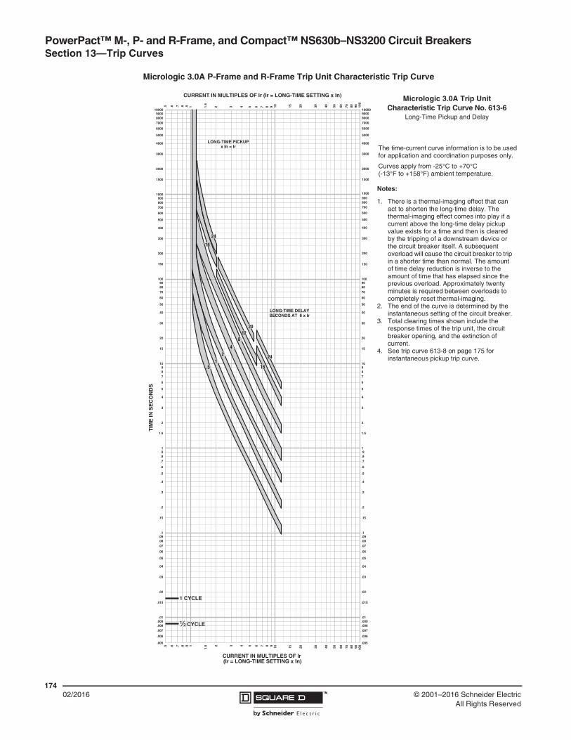
PowerPact™ M-, P- and R-Frame, and Compact™ NS630b–NS3200 Circuit Breakers Section 13—Trip Curves
17402/2016 ™ © 2001–2016 Schneider Electric
All Rights Reserved
Micrologic 3.0A P-Frame and R-Frame Trip Unit Characteristic Trip Curve
1.51
1
CURRENT IN MULTIPLES OF Ir (Ir = LONG-TIME SETTING x In)
CURRENT IN MULTIPLES OF Ir (Ir = LONG-TIME SETTING x In)
.5 .6 .7 .8 .9 1.5
2 3 4 5 6 7 8 9 10 15 20 30 40 50 60 70 80 90 100
.5 .6 .7 .8 .9 2 3 4 5 6 7 8 9 10 15 20 30 40 50 60 70 80 90 100
200
300
400
500
600
700
8009001000
1500
2000
3000
4000
6000
7000
80009000
5000
10000
.005
.006
.007
.008
.009.01
.015
.02
.03
.04
.05
.06
.07
.08
.09.1
.005
.006
.007
.008
.009
.01
.015
.02
.03
.04
.05
.06
.07
.08
.09
.1
.15
.2
.3
.4
.5
.6
.7
.8
.91
.15
.2
.3
.4
.5
.6
.7
.8
.91
1.5
2
3
4
5
6
7
89
10
1.5
2
3
4
5
6
7
8910
15
20
30
40
50
60
70
8090
100
15
20
30
40
50
60
70
8090100
150
200
300
400
500
600
700
800900
1000
1500
2000
3000
4000
5000
6000
7000
80009000
10000
TIM
E IN
SE
CO
ND
S
CYCLE21
1 CYCLE
150
24
2012
.5
8
42
1
16
24
16
LONG-TIME PICKUPx In = Ir
LONG-TIME DELAYSECONDS AT 6 x Ir
MICROLOGIC® 3.0 A TRIP UNITCHARACTERISTIC TRIP CURVE NO. 613-6
Long-time Pickup and Delay
The time-current curve information is to be usedfor application and coordination purposes only.
Curves apply from -25°C to +70°C (-13°F to +158°F) ambient temperature.
Notes:
1. There is a thermal-imaging effect that can acto shorten the long-time delay. The thermal-imaging effect comes into play if a currentabove the long-time delay pickup value existfor a time and then is cleared by the tripping a downstream device or the circuit breakeritself. A subsequent overload will cause thecircuit breaker to trip in a shorter time thannormal. The amount of time delay reduction iinverse to the amount of time that has elapsesince the previous overload. Approximately 2minutes is required between overloads tocompletely reset thermal-imaging.
2. The end of the curve is determined by theinstantaneous setting.
3. Total clearing times shown include theresponse times of the trip unit, the circuitbreaker opening, and the extinction of thecurrent.
4. See 613-8 for instantaneous pickup trip curv
Micrologic 3.0A Trip UnitCharacteristic Trip Curve No. 613-6
Long-Time Pickup and Delay
The time-current curve information is to be used for application and coordination purposes only.
Curves apply from -25°C to +70°C (-13°F to +158°F) ambient temperature.
Notes:
1. There is a thermal-imaging effect that can act to shorten the long-time delay. The thermal-imaging effect comes into play if a current above the long-time delay pickup value exists for a time and then is cleared by the tripping of a downstream device or the circuit breaker itself. A subsequent overload will cause the circuit breaker to trip in a shorter time than normal. The amount of time delay reduction is inverse to the amount of time that has elapsed since the previous overload. Approximately twenty minutes is required between overloads to completely reset thermal-imaging.
2. The end of the curve is determined by the instantaneous setting of the circuit breaker.
3. Total clearing times shown include the response times of the trip unit, the circuit breaker opening, and the extinction of current.
4. See trip curve 613-8 on page 175 for instantaneous pickup trip curve.

PowerPact™ M-, P- and R-Frame, and Compact™ NS630b–NS3200 Circuit BreakersSection 13—Trip Curves
17502/2016™© 2001–2016 Schneider Electric
All Rights Reserved
Micrologic 3.0A P-Frame and R-Frame Trip Unit Characteristic Trip Curve
1.51
1
MULTIPLES OF SENSOR RATING (In)
MULTIPLES OF SENSOR RATING (In)
.5 .6 .7 .8 .9 1.5
2 3 4 5 6 7 8 9 10 15 20 30 40 50 60 70 80 90 100
.5 .6 .7 .8 .9 2 3 4 5 6 7 8 9 10 15 20 30 40 50 60 70 80 90 100
200
300
400
500
600
700
8009001000
1500
2000
3000
4000
6000
7000
80009000
5000
10000
.005
.006
.007
.008
.009.01
.015
.02
.03
.04
.05
.06
.07
.08
.09.1
.005
.006
.007
.008
.009
.01
.015
.02
.03
.04
.05
.06
.07
.08
.09
.1
.15
.2
.3
.4
.5
.6
.7
.8
.91
.15
.2
.3
.4
.5
.6
.7
.8
.91
1.5
2
3
4
5
6
7
89
10
1.5
2
3
4
5
6
7
8910
15
20
30
40
50
60
70
8090
100
15
20
30
40
50
60
70
8090100
150
200
300
400
500
600
700
800900
1000
1500
2000
3000
4000
5000
6000
7000
80009000
10000
TIM
E IN
SE
CO
ND
S
CYCLE21
1 CYCLE
150
1.5 x
INSTANTANEOUSPICKUP
x In
5 x 10 x
2 x 3 x 4 x 6 x 8 x 12 x
MICROLOGIC® 3.0 A TRIP UNITCHARACTERISTIC TRIP CURVE NO. 613-8
Instantaneous Pickup1.5x-12x
The time-current curve information is to be usedfor application and coordination purposes only.
Curves apply from -25°C to +70°C (-13°F to +158°F) ambient temperature.
Instantaneous override values are given on 613-10.
Notes:
1. The end of the curve is determined by theinterrupting rating of the circuit breaker.
2. Total clearing times shown include theresponse times of the trip unit, the circuitbreaker opening, and the extinction of thecurrent.
3. The instantaneous region of the trip curveshows maximum total clearing times. Actualclearing times in this region can varydepending on the circuit breaker mechanismdesign and other factors. The actual clearingtime can be considerably faster than indicatedContact your local Sales Office for additionalinformation.
4. See 613-6 for long-time pickup and delay tripcurves.
Micrologic 3.0A Trip UnitCharacteristic Trip Curve No. 613-8
Instantaneous Pickup, 1.5X to 12X
The time-current curve information is to be used for application and coordination purposes only.Curves apply from -25°C to +10°C (-13°F to +158°F) ambient temperature.Instantaneous override values are given on 613-10.
Notes:
1. The end of the curve is determined by the interrupting rating of the circuit breaker.
2. Total clearing times shown include the response times of the trip unit, the circuit breaker opening, and the extinction of current.
3. The instantaneous region of the trip curve shows maximum total clearing times. Actual clearing times in this region can vary depending on the circuit breaker mechanism design and other factors. The actual clearing time can be considerably faster than indicated. Contact your local sales office for additional information.
4. See trip curve 613-6 on page 174 for long-time pickup and delay trip curves.
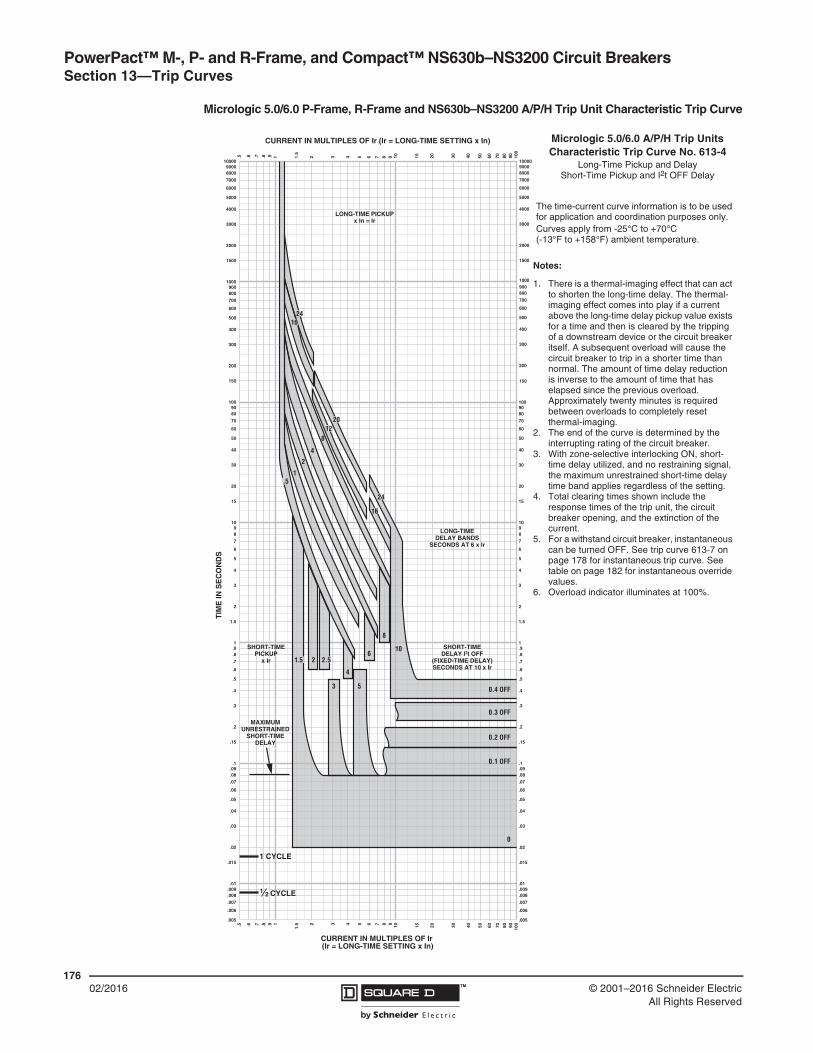
PowerPact™ M-, P- and R-Frame, and Compact™ NS630b–NS3200 Circuit Breakers Section 13—Trip Curves
17602/2016 ™ © 2001–2016 Schneider Electric
All Rights Reserved
Micrologic 5.0/6.0 P-Frame, R-Frame and NS630b–NS3200 A/P/H Trip Unit Characteristic Trip Curve
1.51
1
CURRENT IN MULTIPLES OF Ir (Ir = LONG-TIME SETTING x In)
CURRENT IN MULTIPLES OF Ir (Ir = LONG-TIME SETTING x In)
.5 .6 .7 .8 .9 1.5
2 3 4 5 6 7 8 9 10 15 20 30 40 50 60 70 80 90 100
.5 .6 .7 .8 .9 2 3 4 5 6 7 8 9 10 15 20 30 40 50 60 70 80 90 100
200
300
400
500
600
700
8009001000
1500
2000
3000
4000
6000
7000
80009000
5000
10000
.005
.006
.007
.008
.009.01
.015
.02
.03
.04
.05
.06
.07
.08
.09.1
.005
.006
.007
.008
.009
.01
.015
.02
.03
.04
.05
.06
.07
.08
.09
.1
.15
.2
.3
.4
.5
.6
.7
.8
.91
.15
.2
.3
.4
.5
.6
.7
.8
.91
1.5
2
3
4
5
6
7
89
10
1.5
2
3
4
5
6
7
8910
15
20
30
40
50
60
70
8090
100
15
20
30
40
50
60
70
8090100
150
200
300
400
500
600
700
800900
1000
1500
2000
3000
4000
5000
6000
7000
80009000
10000
TIM
E IN
SE
CO
ND
S
CYCLE21
1 CYCLE
150
24
20
.5
24
16
128
8
6
4
2.51.5 2
3 5
10
4
2
1
16
0.4 OFF
0.3 OFF
0.2 OFF
0.1 OFF
0
LONG-TIME PICKUPx In = Ir
LONG-TIMEDELAY BANDS
SECONDS AT 6 x Ir
MAXIMUMUNRESTRAINED
SHORT-TIMEDELAY
SHORT-TIMEDELAY I2t OFF
(FIXED-TIME DELAY)SECONDS AT 10 x Ir
SHORT-TIMEPICKUP
x Ir
MICROLOGIC® 5.0/6.0 A/P/H TRIP UNITCHARACTERISTIC TRIP CURVE NO. 613-4
Long-time Pickup and DelayShort-time Pickup and I2t OFF Delay
The time-current curve information is to be usefor application and coordination purposes only
Curves apply from -25°C to +70°C (-13°F to +158°F) ambient temperature.
Notes:
1. There is a thermal-imaging effect that can acto shorten the long-time delay. The thermal-imaging effect comes into play if a currentabove the long-time delay pickup value exisfor a time and then is cleared by the trippinga downstream device or the circuit breakeritself. A subsequent overload will cause thecircuit breaker to trip in a shorter time thannormal. The amount of time delay reduction inverse to the amount of time that has elapssince the previous overload. Approximately 2minutes is required between overloads tocompletely reset thermal-imaging.
2. The end of the curve is determined by theinterrupting rating of the circuit breaker.
3. With zone-selective interlocking on, short-timdelay utilized and no restraining signal, themaximum unrestrained short-time delay timeband applies regardless of the setting.
4. Total clearing times shown include theresponse times of the trip unit, the circuitbreaker opening, and the extinction of thecurrent.
5. For a withstand circuit breaker, instantaneoucan be turned OFF. See 613-7 forinstantaneous trip curve. See 613-10 forinstantaneous override values.
6. Overload indicator illuminates at 100%.
Micrologic 5.0/6.0 A/P/H Trip UnitsCharacteristic Trip Curve No. 613-4
Long-Time Pickup and DelayShort-Time Pickup and I2t OFF Delay
The time-current curve information is to be used for application and coordination purposes only.Curves apply from -25°C to +70°C (-13°F to +158°F) ambient temperature.
Notes:
1. There is a thermal-imaging effect that can act to shorten the long-time delay. The thermal-imaging effect comes into play if a current above the long-time delay pickup value exists for a time and then is cleared by the tripping of a downstream device or the circuit breaker itself. A subsequent overload will cause the circuit breaker to trip in a shorter time than normal. The amount of time delay reduction is inverse to the amount of time that has elapsed since the previous overload. Approximately twenty minutes is required between overloads to completely reset thermal-imaging.
2. The end of the curve is determined by the interrupting rating of the circuit breaker.
3. With zone-selective interlocking ON, short-time delay utilized, and no restraining signal, the maximum unrestrained short-time delay time band applies regardless of the setting.
4. Total clearing times shown include the response times of the trip unit, the circuit breaker opening, and the extinction of the current.
5. For a withstand circuit breaker, instantaneous can be turned OFF. See trip curve 613-7 on page 178 for instantaneous trip curve. See table on page 182 for instantaneous override values.
6. Overload indicator illuminates at 100%.
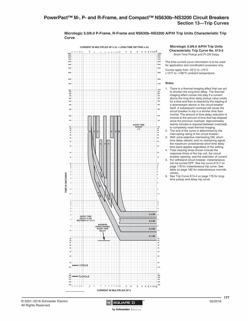
PowerPact™ M-, P- and R-Frame, and Compact™ NS630b–NS3200 Circuit BreakersSection 13—Trip Curves
17702/2016™© 2001–2016 Schneider Electric
All Rights Reserved
Micrologic 5.0/6.0 P-Frame, R-Frame and NS630b–NS3200 A/P/H Trip Units Characteristic Trip Curve
1.51
1
CURRENT IN MULTIPLES OF Ir (Ir = LONG-TIME SETTING x In)
CURRENT IN MULTIPLES OF Ir (I LONG TIME SETTING I )
.5 .6 .7 .8 .9 1.5
2 3 4 5 6 7 8 9 10 15 20 30 40 50 60 70 80 90 100
.5 .6 .7 .8 .9 2 3 4 5 6 7 8 9 10 15 20 30 40 50 60 70 80 90 100
200
300
400
500
600
700
8009001000
1500
2000
3000
4000
6000
7000
80009000
5000
10000
.005
.006
.007
.008
.009.01
.015
.02
.03
.04
.05
.06
.07
.08
.09.1
.005
.006
.007
.008
.009
.01
.015
.02
.03
.04
.05
.06
.07
.08
.09
.1
.15
.2
.3
.4
.5
.6
.7
.8
.91
.15
.2
.3
.4
.5
.6
.7
.8
.91
1.5
2
3
4
5
6
7
89
10
1.5
2
3
4
5
6
7
8910
15
20
30
40
50
60
70
8090
100
15
20
30
40
50
60
70
8090100
150
200
300
400
500
600
700
800900
1000
1500
2000
3000
4000
5000
6000
7000
80009000
10000
TIM
E IN
SE
CO
ND
S
CYCLE21
1 CYCLE
150
2.52
3 4 5
6 8 101.5
0.4 ON
0.4 ON
0.2 ON
0.3 ON
0.1 ON
0.3 ON
0.2 ON
0.1 ON
SHORT-TIMEDELAY I2t ON
SECONDS AT 10 x Ir
SHORT-TIMEPICKUP
x Ir
MAXIMUMUNRESTRAINED
SHORT-TIMEDELAY
MICROLOGIC® 5.0/6.0 A/P/H TRIP UNITCHARACTERISTIC TRIP CURVE NO. 613-5
Short-time Pickup and I2t ON Delay
The time-current curve information is to be usedfor application and coordination purposes only.
Curves apply from -25°C to +70°C (-13°F to +158°F) ambient temperature.
Notes:
1. There is a thermal-imaging effect that can actto shorten the long-time delay. The thermal-imaging effect comes into play if a currentabove the long-time delay pickup value existsfor a time and then is cleared by the tripping oa downstream device or the circuit breakeritself. A subsequent overload will cause thecircuit breaker to trip in a shorter time thannormal. The amount of time delay reduction isinverse to the amount of time that has elapsedsince the previous overload. Approximately 20minutes is required between overloads tocompletely reset thermal-imaging.
2. The end of the curve is determined by theinterrupting rating of the circuit breaker.
3. With zone-selective interlocking on, short-timedelay utilized and no restraining signal, themaximum unrestrained short-time delay timeband applies regardless of the setting.
4. Total clearing times shown include theresponse times of the trip unit, the circuitbreaker opening, and the extinction of thecurrent.
5. For a withstand circuit breaker, instantaneouscan be turned OFF. See 613-7 forinstantaneous trip curve. See 613-10 forinstantaneous override values.
6. See 613-4 for long-time pickup and delay tripcurve.
Micrologic 5.0/6.0 A/P/H Trip UnitsCharacteristic Trip Curve No. 613-5
Short-Time Pickup and I2t ON Delay
The time-current curve information is to be used for application and coordination purposes only.
Curves apply from -25°C to +70°C(-13°F to +158°F) ambient temperature.
Notes:
1. There is a thermal-imaging effect that can act to shorten the long-time delay. The thermal-imaging effect comes into play if a current above the long-time delay pickup value exists for a time and then is cleared by the tripping of a downstream device or the circuit breaker itself. A subsequent overload will cause the circuit breaker to trip in a shorter time than normal. The amount of time delay reduction is inverse to the amount of time that has elapsed since the previous overload. Approximately twenty minutes is required between overloads to completely reset thermal-imaging.
2. The end of the curve is determined by the interrupting rating of the circuit breaker.
3. With zone-selective interlocking ON, short-time delay utilized, and no restraining signal, the maximum unrestrained short-time delay time band applies regardless of the setting.
4. Total clearing times shown include the response times of the trip unit, the circuit breaker opening, and the extinction of current.
5. For withstand circuit breaker, instantaneous can be turned OFF. See trip curve 613-7 on page 178 for instantaneous trip curve. See table on page 182 for instantaneous override values.
6. See Trip Curve 613-4 on page 176 for long-time pickup and delay trip curve.

PowerPact™ M-, P- and R-Frame, and Compact™ NS630b–NS3200 Circuit Breakers Section 13—Trip Curves
17802/2016 ™ © 2001–2016 Schneider Electric
All Rights Reserved
Micrologic 5.0/6.0 P-Frame, R-Frame and NS630b–NS3200 A/P/H Trip Units Characteristic Trip Curve
1.51
1
MULTIPLES OF SENSOR RATING (In)
MULTIPLES OF SENSOR RATING (In)
.5 .6 .7 .8 .9 1.5
2 3 4 5 6 7 8 9 10 15 20 30 40 50 60 70 80 90 100
.5 .6 .7 .8 .9 2 3 4 5 6 7 8 9 10 15 20 30 40 50 60 70 80 90 100
200
300
400
500
600
700
8009001000
1500
2000
3000
4000
6000
7000
80009000
5000
10000
.005
.006
.007
.008
.009.01
.015
.02
.03
.04
.05
.06
.07
.08
.09.1
.005
.006
.007
.008
.009
.01
.015
.02
.03
.04
.05
.06
.07
.08
.09
.1
.15
.2
.3
.4
.5
.6
.7
.8
.91
.15
.2
.3
.4
.5
.6
.7
.8
.91
1.5
2
3
4
5
6
7
89
10
1.5
2
3
4
5
6
7
8910
15
20
30
40
50
60
70
8090
100
15
20
30
40
50
60
70
8090100
150
200
300
400
500
600
700
800900
1000
1500
2000
3000
4000
5000
6000
7000
80009000
10000
TIM
E IN
SE
CO
ND
S
CYCLE21
1 CYCLE
150
INSTANTANEOUSPICKUP
x In
10 x
2 x 3 x 4 x 6 x 8 x 12 x 15 x
MICROLOGIC® 5.0/6.0 A/P/H TRIP UNITCHARACTERISTIC TRIP CURVE NO. 613-7
Instantaneous Pickup2x–15x and OFF
The time-current curve information is to be usedfor application and coordination purposes only.
Curves apply from -25°C to +70°C (-13°F to +158°F) ambient temperature.
Notes:
1. The end of the curve is determined by theinterrupting rating of the circuit breaker.
2. Total clearing times shown include theresponse times of the trip unit, the circuitbreaker opening, and the extinction of thecurrent.
3. The instantaneous region of the trip curveshows maximum total clearing times. Actualclearing times in this region can varydepending on the circuit breaker mechanismdesign and other factors. The actual clearingtime can be considerably faster than indicatedContact your local Sales Office for additionalinformation.
4. For a withstand circuit breaker, instantaneouscan be turned OFF. See 613-7 forinstantaneous trip curve. See 613-10 forinstantaneous override values.
5. See 613-4 and 613-5 for long-time pickup,long-time delay, short-time pickup, and short-time delay trip curves.
Micrologic 5.0/6.0 Trip UnitsCharacteristic Trip Curve No. 613-7Instantaneous Pickup, 2X to 15X and OFF
The time-current curve information is to be used for application and coordination purposes only.
Curves apply from -30°C to +60°C (-22°F to +140°F) ambient temperature.
Notes:
1. The end of the curve is determined by the interrupting rating of the circuit breaker.
2. Total clearing times shown include the response times of the trip unit, the circuit breaker opening, and the extinction of current.
3. The instantaneous region of the trip curve shows maximum total clearing times. Actual clearing times in this region can vary depending on the circuit breaker mechanism design and other factors. The actual clearing time can be considerably faster than indicated. Contact your local sales office for additional information.
4. For a withstand circuit breaker, instantaneous can be turned OFF. See trip curve 613-7 on page 178 for the instantaneous trip curve. See table on page 182 for the instantaneous override values.
5. See trip curve 613-4 on page 176 and trip curve 613-5 on page 177 for long-time pickup, long-time delay, short-time pickup and short-time delay trip curves.

PowerPact™ M-, P- and R-Frame, and Compact™ NS630b–NS3200 Circuit BreakersSection 13—Trip Curves
17902/2016™© 2001–2016 Schneider Electric
All Rights Reserved
Micrologic 6.0 P-Frame, R-Frame and NS630b–NS3200 A/P/H Trip Units with Adjustable Ground-fault Pickup and Delay Characteristic Trip Curve
.15.1
.1
MULTIPLES OF SENSOR RATING (In)
MULTIPLES OF SENSOR RATING (In)
.05
.06
.07
.08
.09
.15
.2 .3 .4 .5 .6 .7 .8 .9 1 1.5
2 3 4 5 6 7 8 9 10
.05
.06
.07
.08
.09 .2 .3 .4 .5 .6 .7 .8 .9 1
1.5 2 3 4 5 6 7 8 9 10
200
300
400
500
600
700
8009001000
1500
2000
3000
4000
6000
7000
80009000
5000
10000
.005
.006
.007
.008
.009.01
.015
.02
.03
.04
.05
.06
.07
.08
.09.1
.005
.006
.007
.008
.009
.01
.015
.02
.03
.04
.05
.06
.07
.08
.09
.1
.15
.2
.3
.4
.5
.6
.7
.8
.91
.15
.2
.3
.4
.5
.6
.7
.8
.91
1.5
2
3
4
5
6
7
89
10
1.5
2
3
4
5
6
7
8910
15
20
30
40
50
60
70
8090
100
15
20
30
40
50
60
70
8090100
150
200
300
400
500
600
700
800900
1000
1500
2000
3000
4000
5000
6000
7000
80009000
10000
TIM
E IN
SE
CO
ND
S
CYCLE21
1 CYCLE
150
0.4 ON0.3 ON
0.2 ON
0.1 ON
0.4 OFF
0.3 OFF
0.2 OFF
0.1 OFF
0
GROUND-FAULTDELAY BANDS
I2t ON
GROUND-FAULTPICKUP
x In
GROUND-FAULTDELAY BANDS
I2t OFF(FIXED DELAY)
DELAYSECONDS AT 1 x In
0.10.20.30.4
MAXIMUMUNRESTRAINEDGROUND-FAULT
DELAY
0.5 0.7 0.9
0.4
0.6 0.8 1.0
0.3
MICROLOGIC® 6.0 A/P/H TRIP UNIT WITH ADJUSTABLE GROUND-FAULT
PICKUP AND DELAY CHARACTERISTIC TRIP CURVE NO. 613-1
Ground-fault I2t OFF and ONIn ≤ 400 A
The time-current curve information is to be usedfor application and coordination purposes only.
Curves apply from -25°C to +70°C (-13°F to +158°F) ambient temperature.
Micrologic 6.0 A/P/H Trip Unitswith Adjustable Ground-Fault Pickup and
DelayCharacteristic Trip Curve No. 613-1
Ground Fault I2t OFF and ON
In ≤ 400 A
The time-current curve information is to be used for application and coordination purposes only.
Curves apply from -25°C to +70°C (-13°F to +158°F) ambient temperature.

PowerPact™ M-, P- and R-Frame, and Compact™ NS630b–NS3200 Circuit Breakers Section 13—Trip Curves
18002/2016 ™ © 2001–2016 Schneider Electric
All Rights Reserved
Micrologic 6.0 P-Frame, R-Frame and NS630b–NS3200 A/P/H Trip Units with Adjustable Ground-fault Pickup and Delay Characteristic Trip Curve
.15.1
.1
MULTIPLES OF SENSOR RATING (In)
MULTIPLES OF SENSOR RATING (In)
.05
.06
.07
.08
.09
.15
.2 .3 .4 .5 .6 .7 .8 .9 1 1.5
2 3 4 5 6 7 8 9 10
.05
.06
.07
.08
.09 .2 .3 .4 .5 .6 .7 .8 .9 1
1.5 2 3 4 5 6 7 8 9 10
200
300
400
500
600
700
8009001000
1500
2000
3000
4000
6000
7000
80009000
5000
10000
.005
.006
.007
.008
.009.01
.015
.02
.03
.04
.05
.06
.07
.08
.09.1
.005
.006
.007
.008
.009
.01
.015
.02
.03
.04
.05
.06
.07
.08
.09
.1
.15
.2
.3
.4
.5
.6
.7
.8
.91
.15
.2
.3
.4
.5
.6
.7
.8
.91
1.5
2
3
4
5
6
7
89
10
1.5
2
3
4
5
6
7
8910
15
20
30
40
50
60
70
8090
100
15
20
30
40
50
60
70
8090100
150
200
300
400
500
600
700
800900
1000
1500
2000
3000
4000
5000
6000
7000
80009000
10000
TIM
E IN
SE
CO
ND
S
CYCLE21
1 CYCLE
150
0.20.2 ON
0.4 ON
0.3 ON
0.1 ON
0.4 OFF
0.3 OFF
0.2 OFF
0.1 OFF
0
GROUND-FAULTDELAY BANDS
I2t ON
GROUND-FAULTPICKUP
x In
GROUND-FAULTDELAY BANDS
I2t OFF(FIXED DELAY)
DELAYSECONDS AT 1 x In
0.10.20.30.4
MAXIMUMUNRESTRAINEDGROUND-FAULT
DELAY
0.3 0.5 0.7 0.9
0.4 0.6 0.8 1.0
MICROLOGIC® 6.0 A/P/H TRIP UNIT WITH ADJUSTABLE GROUND-FAULT
PICKUP AND DELAY CHARACTERISTIC TRIP CURVE NO. 613-2
Ground-fault I2t OFF and ON400 A < In ≤ 1200 A
The time-current curve information is to be usedfor application and coordination purposes only.
Curves apply from -25°C to +70°C (-13°F to +158°F) ambient temperature.
Micrologic 6.0 A/P/H Trip Unitswith Adjustable Ground-Fault Pickup and
DelayCharacteristic Trip Curve No. 613-2
Ground Fault I2t OFF and ON
400 A < In ≤ 1200 A
The time-current curve information is to be used for application and coordination purposes only.
Curves apply from -25°C to +70°C (-13°F to +158°F) ambient temperature.

PowerPact™ M-, P- and R-Frame, and Compact™ NS630b–NS3200 Circuit BreakersSection 13—Trip Curves
18102/2016™© 2001–2016 Schneider Electric
All Rights Reserved
Micrologic 6.0 P-Frame, R-Frame and NS630b–NS3200 A/P/H Trip Units with Adjustable Ground-fault Pickup and Delay Characteristic Trip Curve
.15.1
.1
AMPERES x 103
AMPERES x 103
.05
.06
.07
.08
.09
.15
.2 .3 .4 .5 .6 .7 .8 .9 1 1.5
2 3 4 5 6 7 8 9 10
.05
.06
.07
.08
.09 .2 .3 .4 .5 .6 .7 .8 .9 1
1.5 2 3 4 5 6 7 8 9 10
200
300
400
500
600
700
8009001000
1500
2000
3000
4000
6000
7000
80009000
5000
10000
.005
.006
.007
.008
.009.01
.015
.02
.03
.04
.05
.06
.07
.08
.09.1
.005
.006
.007
.008
.009
.01
.015
.02
.03
.04
.05
.06
.07
.08
.09
.1
.15
.2
.3
.4
.5
.6
.7
.8
.91
.15
.2
.3
.4
.5
.6
.7
.8
.91
1.5
2
3
4
5
6
7
89
10
1.5
2
3
4
5
6
7
8910
15
20
30
40
50
60
70
8090
100
15
20
30
40
50
60
70
8090100
150
200
300
400
500
600
700
800900
1000
1500
2000
3000
4000
5000
6000
7000
80009000
10000
TIM
E IN
SE
CO
ND
S
CYCLE21
1 CYCLE
150
0.1 ON0.3 ON
0.4 ON0.2 ON
0.4 OFF
500
A
720
A 1040
A12
00 A
880
A
640
A
800
A96
0 A
1120
A
0.3 OFF
0.2 OFF
0.1 OFF
0
GROUND-FAULTDELAY BANDS
I2t ON
GROUND-FAULTPICKUP
x In
GROUND-FAULTDELAY BANDS
I2t OFF(FIXED DELAY)
DELAYSECONDS AT 1 x In
0.10.20.30.4
MAXIMUMUNRESTRAINEDGROUND-FAULT
DELAY
MICROLOGIC® 6.0 A/P/H TRIP UNIT WITH ADJUSTABLE GROUND-FAULT
PICKUP AND DELAY CHARACTERISTIC TRIP CURVE NO. 613-3
Ground-fault I2t OFF and ONIn > 1200 A
The time-current curve information is to be usedfor application and coordination purposes only.
Curves apply from -25°C to +70°C (-13°F to +158°F) ambient temperature.
Micrologic 6.0 A/P/H Trip Unitswith Adjustable Ground-Fault Pickup and
DelayCharacteristic Trip Curve No. 613-3
Ground Fault I2t OFF and ON
In > 1200 A
The time-current curve information is to be used for application and coordination purposes only.
Curves apply from -25°C to +70°C (-13°F to +158F) ambient temperature.

PowerPact™ M-, P- and R-Frame, and Compact™ NS630b–NS3200 Circuit Breakers Section 13—Trip Curves
18202/2016 ™ © 2001–2016 Schneider Electric
All Rights Reserved
Table 102: Instantaneous Override Values Characteristic Trip Curve
UL/IEC Circuit BreakerInstantaneous Override1
(kA Peak)2
1 Faults at or above instantaneous override value will be cleared at 25 msec or less.2 Test X/R=4.9; divide by 2.1 for nominal RMS
UL/IEC Circuit BreakerInstantaneous Override1
(kA Peak)2
RG 600 130 ± 10% MG300 20 ± 15%
RG 800 130 ± 10% MG350 20 ± 15%
RG 1000 130 ± 10% MG400 20 ± 15%
RG 1200 130 ± 10% MG450 20 ± 15%
RG 1600 130 ± 10% MG500 20 ± 15%
RG 2000 130 ± 10% MG600 20 ± 15%
RG 2500 130 ± 10% MG700 20 ± 15%
RJ 600 90 ± 15% MG800 20 ± 15%
RJ 800 90 ± 15% MJ300 20 ± 15%
RJ 1000 90 ± 15% MJ350 20 ± 15%
RJ 1200 90 ± 15% MJ400 20 ± 15%
RJ 1600 90 ± 15% MJ450 20 ± 15%
RJ 2000 90 ± 15% MJ500 20 ± 15%
RJ 2500 90 ± 15% MJ600 20 ± 15%
RK 600 130 ± 10% MJ700 20 ± 15%
RK 800 130 ± 10% MJ800 20 ± 15%
RK 1000 130 ± 10%
IEC Circuit BreakerInstantaneous Override1
(kA Peak)2 RK 1200 130 ± 10%
RK 1600 130 ± 10%
RK 2000 130 ± 10% NS 800bN 130 ± 10%
RK 2500 130 ± 10% NS1000bN 130 ± 10%
RL 600 90 ± 15% NS1250bN 130 ± 10%
RL 800 90 ± 15% NS1600bN 130 ± 10%
RL 1000 90 ± 15% NS2000N 130 ± 10%
RL 1200 90 ± 15% NS2500N 90 ± 15%
RL 1600 90 ± 15% NS 3200N 90 ± 15%
RL 2000 90 ± 15% NS 800bH 90 ± 15%
RL 2500 90 ± 15% NS1000bH 90± 15%
PG 250 55 ± 10% NS1250bH 55 ± 10%
PG 400 55 ± 10% NS1600bH 55 ± 10%
PG 600 55 ± 10% NS2000H 55 ± 10%
PG 800 55 ± 10% NS2500H 55 ± 10%
PG 1000 55 ± 10% NS3200H 55 ± 10%
PG 1200 55 ± 10% NS630bN 55 ± 10%
PJ 250 15 ± 10% NS800N 55 ± 10%
PJ 400 22 ± 10% NS1000N 55 ± 10%
PJ 600 22 ± 10% NS1250N 55 ± 10%
PJ 800 22 ± 10% NS1600N 55 ± 10%
PJ 1000 22 ± 10% NS630bH 55 ± 10%
PJ 1200 22 ± 10% NS800H 55 ± 10%
PK 250 55 ± 10% NS1000H 55 ± 10%
PK 400 55 ± 10% NS1250H 55 ± 10%
PK 600 55 ± 10% NS1600H 55 ± 10%
PK 800 55 ± 10% NS630bL 55 ± 10%
PK 1000 55 ± 10% NS800L 55 ± 10%
PK 1200 55 ± 10% NS1000L 55 ± 10%
PL 250 20 ± 10% NS1250L 55 ± 10%
PL 400 22 ± 10% NS1600L 55 ± 10%
PL 600 22 ± 10%
PL 800 22 ± 10%
PL 1000 22 ± 10%
PL 1200 22 ± 10%

PowerPact™ M-, P- and R-Frame, and Compact™ NS630b–NS3200 Circuit BreakersSection 13—Trip Curves
18302/2016™© 2001–2016 Schneider Electric
All Rights Reserved
Basic Electronic Trip Unit 1.0M, P-Frame 600 A MDP Characteristic Trip Curve
1.51
1
MULTIPLES OF SENSOR RATING (In)
MULTIPLES OF SENSOR RATING (In)
.5 .6 .7 .8 .9 1.5
2 3 4 5 6 7 8 9 10 15 20 30 40 50 60 70 80 90 100
.5 .6 .7 .8 .9 2 3 4 5 6 7 8 9 10 15 20 30 40 50 60 70 80 90 100
200
300
400
500
600
700
8009001000
1500
2000
3000
4000
6000
7000
80009000
5000
10000
.005
.006
.007
.008
.009.01
.015
.02
.03
.04
.05
.06
.07
.08
.09.1
.005
.006
.007
.008
.009
.01
.015
.02
.03
.04
.05
.06
.07
.08
.09
.1
.15
.2
.3
.4
.5
.6
.7
.8
.91
.15
.2
.3
.4
.5
.6
.7
.8
.91
1.5
2
3
4
5
6
7
89
10
1.5
2
3
4
5
6
7
8910
15
20
30
40
50
60
70
8090
100
15
20
30
40
50
60
70
8090100
150
200
300
400
500
600
700
800900
1000
1500
2000
3000
4000
5000
6000
7000
80009000
10000
TIM
E IN
SE
CO
ND
S
CYCLE21
1 CYCLE
150
INSTANTANEOUSPICKUP
x In
4 x5.5 x2.5 x 10.5 x
13.5 x8 x
6.5 x16 x2 x
600 A ELECTRONIC TRIP 1.0MCHARACTERISTIC TRIP CURVE NO. 613-13
Instantaneous Pickup2x-16x
The time-current curve information is to be usedfor application and coordination purposes only.
Curves apply from -25°C to +70°C (-13°F to +158°F) ambient temperature.
Instantaneous override values are given on 613-10.
Notes:
1. The end of the curve is determined by theinterrupting rating of the circuit breaker.
2. Total clearing times shown include theresponse times of the trip unit, the circuitbreaker opening, and the extinction of thecurrent.
3. The instantaneous region of the trip curveshows maximum total clearing times. Actualclearing times in this region can varydepending on the circuit breaker mechanismdesign and other factors. The actual clearingtime can be considerably faster than indicateContact your local Sales Office for additionalinformation.
Basic Electronic Trip Unit 1.0M, 600 ACharacteristic Trip Curve No. 613-13
Instantaneous Pickup, 2X to 16X
The time-current curve information is to be used for application and coordination purposes only.
Curves apply from -25°C to +70°C(-13°F to +158°F) ambient temperature.
Instantaneous override values are given on page 182.
Notes:
1. The end of the curve is determined by the interrupting rating of the circuit breaker.
2. Total clearing times shown include the response times of the trip unit, the circuit breaker opening, and the extinction of current.
3. The instantaneous region of the trip curve shows maximum total clearing times. Actual clearing times in this region can vary depending on the circuit breaker mechanism design and other factors. The actual clearing time can be considerably faster than indicated. Contact your local sales office for additional information.

PowerPact™ M-, P- and R-Frame, and Compact™ NS630b–NS3200 Circuit Breakers Section 13—Trip Curves
18402/2016 ™ © 2001–2016 Schneider Electric
All Rights Reserved
Basic Electronic Trip Unit 1.0M P-Frame 800–1200A MCP Characteristic Trip Curve
1.51
1
MULTIPLES OF SENSOR RATING (In)
MULTIPLES OF SENSOR RATING (In)
.5 .6 .7 .8 .9 1.5
2 3 4 5 6 7 8 9 10 15 20 30 40 50 60 70 80 90 100
.5 .6 .7 .8 .9 2 3 4 5 6 7 8 9 10 15 20 30 40 50 60 70 80 90 100
200
300
400
500
600
700
8009001000
1500
2000
3000
4000
6000
7000
80009000
5000
10000
.005
.006
.007
.008
.009.01
.015
.02
.03
.04
.05
.06
.07
.08
.09.1
.005
.006
.007
.008
.009
.01
.015
.02
.03
.04
.05
.06
.07
.08
.09
.1
.15
.2
.3
.4
.5
.6
.7
.8
.91
.15
.2
.3
.4
.5
.6
.7
.8
.91
1.5
2
3
4
5
6
7
89
10
1.5
2
3
4
5
6
7
8910
15
20
30
40
50
60
70
8090
100
15
20
30
40
50
60
70
8090100
150
200
300
400
500
600
700
800900
1000
1500
2000
3000
4000
5000
6000
7000
80009000
10000
TIM
E IN
SE
CO
ND
S
CYCLE21
1 CYCLE
150
1.5 x
INSTANTANEOUSPICKUP
x In
5 x 10 x
2 x 3 x 4 x 6 x 8 x 12 x
ELECTRONIC TRIP 1.0M800 A–1200 A
CHARACTERISTIC TRIP CURVE NO. 613-11Instantaneous Pickup
1.5x-12x
The time-current curve information is to be usedfor application and coordination purposes only.
Curves apply from -25°C to +70°C (-13°F to +158°F) ambient temperature.
Instantaneous override values are given on 613-10.
Notes:
1. The end of the curve is determined by theinterrupting rating of the circuit breaker.
2. Total clearing times shown include theresponse times of the trip unit, the circuitbreaker opening, and the extinction of thecurrent.
3. The instantaneous region of the trip curveshows maximum total clearing times. Actualclearing times in this region can varydepending on the circuit breaker mechanismdesign and other factors. The actual clearingtime can be considerably faster than indicateContact your local Sales Office for additionalinformation.
Basic Electronic Trip Unit 1.0M800 A–1200 A
Characteristic Trip Curve No. 613-11Instantaneous Pickup, 1.5X to 12X
The time-current curve information is to be used for application and coordination purposes only.
Curves apply from -25°C to +70°C (-13°F to +158°F) ambient temperature.
Instantaneous override values are given on page 182.
Notes:
1. The end of the curve is determined by the interrupting rating of the circuit breaker.
2. Total clearing times shown include the response times of the trip unit, the circuit breaker opening, and the extinction of current.
3. The instantaneous region of the trip curve shows maximum total clearing times. Actual clearing times in this region can vary depending on the circuit breaker mechanism design and other factors. The actual clearing time can be considerably faster than indicated. Contact your local sales office for additional information.

PowerPact™ M-, P- and R-Frame, and Compact™ NS630b–NS3200 Circuit Breakers
18502/2016™© 2001–2016 Schneider Electric
All Rights Reserved
Section 14—Catalog Numbers
685823 ...........................111685824 ...........................111685825 ...........................111685826 ...........................111685827 ...........................111685829 ...........................111AL1200P24K ..................114AL1200P24K ..................118AL1200P25K ..................114AL1200P6KU .................114AL1200P7KU .................114AL1200R53K .................114AL1200R53K .................118AL2500RK .....................114AL800M23K ...................114AL800P6K ......................114AL800P7K ......................114CU1200P24K .................115CU1200P25K .................115CU1200R53K .................115CU250P1K .....................115CU800M23K ..................115CYA1200R5 ...................115CYA1200R7 ...................115CYA400P5 .....................115CYA600P5 .....................115CYA800R7 .....................115LCP48 ............................116LHP48 ............................116LHP8 ..............................116LS10 ..............................116LS8 ................................116LW1 ...............................116LW4 ...............................116LW7 ...............................116MGA263002 .....................70MGA263502 .....................70MGA264002 .....................70MGA264502 .....................70MGA265002 .....................70MGA266002 .....................70MGA267002 .....................70MGA268002 .....................70MGA36300 .......................70MGA36350 .......................70MGA36400 .......................70MGA36450 .......................70MGA36500 .......................70MGA36600 .......................70MGA36700 .......................70MGA36800 .......................70MGL26300 .......................70MGL26350 .......................70MGL26400 .......................70MGL26450 .......................70MGL26500 .......................70MGL26600 .......................70MGL26700 .......................70MGL26800 .......................70MGL36300 .......................70MGL36350 .......................70MGL36400 .......................70MGL36450 .......................70MGL36500 .......................70MGL36600 .......................70MGL36700 .......................70MGL36800 .......................70MICROTUSEAL .............106MJA263002 ......................70MJA263502 ......................70MJA264002 ......................70MJA264502 ......................70MJA265002 ......................70MJA266002 ......................70
MJA267002 ......................70MJA268002 ......................70MJA36300 ........................70MJA36350 ........................70MJA36400 ........................70MJA36450 ........................70MJA36500 ........................70MJA36600 ........................70MJA36700 ........................70MJA36800 ........................70MJL26300 ........................70MJL26350 ........................70MJL26400 ........................70MJL26450 ........................70MJL26500 ........................70MJL26600 ........................70MJL26700 ........................70MJL26800 ........................70MJL36300 ........................70MJL36350 ........................70MJL36400 ........................70MJL36450 ........................70MJL36500 ........................70MJL36600 ........................70MJL36700 ........................70MJL36800 ........................70MPRPAF ........................118MPRPAF ........................118NCTWIRING ..................107NPHFE36160U32R .........94NPHFE36160U33R .........94NPHFE36160U42R .........94NPHFE36160U43R .........94NPHFE36160U44R .........94NPHFE36160U63RE1 .....94NPHFE36160U64RE1 .....94NPHFE36160U73RE1 .....94NPHFE36160U74RE1 .....94NPHLE36063U32R ..........94NPHLE36063U33R ..........94NPHLE36063U42R ..........94NPHLE36063U43R ..........94NPHLE36063U44R ..........94NPHLE36063U63RE1 .....94NPHLE36063U64RE1 .....94NPHLE36063U73RE1 .....94NPHLE36063U74RE1 .....94NPHLE36080U32R ..........94NPHLE36080U33R ..........94NPHLE36080U42R ..........94NPHLE36080U43R ..........94NPHLE36080U44R ..........94NPHLE36080U63RE1 .....94NPHLE36080U64RE1 .....94NPHLE36080U73RE1 .....94NPHLE36080U74RE1 .....94NPHLE36100U32R ..........94NPHLE36100U33R ..........94NPHLE36100U42R ..........94NPHLE36100U43R ..........94NPHLE36100U44R ..........94NPHLE36100U63RE1 .....94NPHLE36100U64RE1 .....94NPHLE36100U73RE1 .....94NPHLE36100U74RE1 .....94NPHLE36125U32R ..........94NPHLE36125U42R ..........94NPHLE36125U43R ..........94NPHLE36125U44R ..........94NPHLE36125U63RE1 .....94NPHLE36125U64RE1 .....94NPHLE36125U73RE1 .....94NPHLE36125U74RE1 .....94NPLLE34063U32R ..........94
NPLLE34063U33R ..........94NPLLE34063U42R ..........94NPLLE34063U43R ..........94NPLLE34063U44R ..........94NPLLE34063U63RE1 ......94NPLLE34063U64RE1 ......94NPLLE34063U73RE1 ......94NPLLE34063U74RE1 ......94NPLLE34080U32R ..........94NPLLE34080U33R ..........94NPLLE34080U42R ..........94NPLLE34080U43R ..........94NPLLE34080U44R ..........94NPLLE34080U63RE1 ......94NPLLE34080U64RE1 ......94NPLLE34080U73RE1 ......94NPLLE34080U74RE1 ......94NPLLE34100U32R ..........94NPLLE34100U33R ..........94NPLLE34100U42R ..........94NPLLE34100U43R ..........94NPLLE34100U44R ..........94NPLLE34100U63RE1 ......94NPLLE34100U64RE1 ......94NPLLE34100U73RE1 ......94NPLLE34100U74RE1 ......94NPNFE36160U32R .........94NPNFE36160U33R .........94NPNFE36160U42R .........94NPNFE36160U43R .........94NPNFE36160U44R .........94NPNFE36160U63RE1 .....94NPNFE36160U64RE1 .....94NPNFE36160U73RE1 .....94NPNFE36160U74RE1 .....94NPNLE36063U32R ..........94NPNLE36063U33R ..........94NPNLE36063U42R ..........94NPNLE36063U43R ..........94NPNLE36063U44R ..........94NPNLE36063U63RE1 .....94NPNLE36063U64RE1 .....94NPNLE36063U73RE1 .....94NPNLE36063U74RE1 .....94NPNLE36080U32R ..........94NPNLE36080U33R ..........94NPNLE36080U42R ..........94NPNLE36080U43R ..........94NPNLE36080U44R ..........94NPNLE36080U63RE1 .....94NPNLE36080U64RE1 .....94NPNLE36080U73RE1 .....94NPNLE36080U74RE1 .....94NPNLE36100U32R ..........94NPNLE36100U33R ..........94NPNLE36100U42R ..........94NPNLE36100U43R ..........94NPNLE36100U44R ..........94NPNLE36100U63RE1 .....94NPNLE36100U64RE1 .....94NPNLE36100U73RE1 .....94NPNLE36100U74RE1 .....94NPNLE36125U32R ..........94NPNLE36125U33R ..........94NPNLE36125U42R ..........94NPNLE36125U43R ..........94NPNLE36125U44R ..........94NPNLE36125U63RE1 .....94NPNLE36125U64RE1 .....94NPNLE36125U73RE1 .....94NPNLE36125U74RE1 .....94NPRLE34063U32R ..........94NPRLE34063U33R ..........94NPRLE34063U42R ..........94
NPRLE34063U43R ..........94NPRLE34063U44R ..........94NPRLE34063U63RE1 .....94NPRLE34063U64RE1 .....94NPRLE34063U73RE1 .....94NPRLE34063U74RE1 .....94NPRLE34080U32R ..........94NPRLE34080U33R ..........94NPRLE34080U42R ..........94NPRLE34080U43R ..........94NPRLE34080U44R ..........94NPRLE34080U63RE1 .....94NPRLE34080U64RE1 .....94NPRLE34080U73RE1 .....94NPRLE34080U74RE1 .....94NRHFE36160U32R .........98NRHFE36160U33R .........98NRHFE36160U42R .........98NRHFE36160U43R .........98NRHFE36160U44R .........98NRHFE36160U63RE1 .....98NRHFE36160U64RE1 .....98NRHFE36200U32R .........98NRHFE36200U33R .........98NRHFE36200U42R .........98NRHFE36200U43R .........98NRHFE36200U44R .........98NRHFE36200U63RE1 .....98NRHFE36200U64RE1 .....98NRHFE36250U32R .........98NRHFE36250U33R .........98NRHFE36250U42R .........98NRHFE36250U43R .........98NRHFE36250U63RE1 .....98NRHFE36250U64RE1 .....98NRHFE36320U32R .........98NRHFE36320U33R .........98NRHFE36320U42R .........98NRHFE36320U43R .........98NRHFE36320U44R .........98NRHFE36320U63RE1 .....98NRHFE36320U64RE1 .....98NRHLFE36250U44R .......98NRNFE36160U32R .........98NRNFE36160U33R .........98NRNFE36160U42R .........98NRNFE36160U43R .........98NRNFE36160U44R .........98NRNFE36160U63RE1 .....98NRNFE36160U64RE1 .....98NRNFE36200U32R .........98NRNFE36200U33R .........98NRNFE36200U42R .........98NRNFE36200U43R .........98NRNFE36200U44R .........98NRNFE36200U63RE1 .....98NRNFE36200U64RE1 .....98NRNFE36250U32R .........98NRNFE36250U33R .........98NRNFE36250U42R .........98NRNFE36250U43R .........98NRNFE36250U44R .........98NRNFE36250U63RE1 .....98NRNFE36250U64RE1 .....98NRNFE36320U32R .........98NRNFE36320U33R .........98NRNFE36320U42R .........98NRNFE36320U43R .........98NRNFE36320U44R .........98NRNFE36320U63RE1 .....98NRNFE36320U64RE1 .....98PDC12P4 .......................115PDC12P44 .....................115PDC6P20 .......................115
PDC6P204 .....................115PGA36025CU31A ............76PGA36025CU33A ............76PGA36025CU41A ............76PGA36025CU43A ............76PGA36025CU44A ............76PGA36025CU63AE1 .......76PGA36025CU64AE1 .......76PGA36025CU73AE1 .......76PGA36025CU74AE1 .......76PGA36025U31A ..............75PGA36025U33A ..............75PGA36025U41A ..............75PGA36025U43A ..............75PGA36025U44A ..............75PGA36025U63AE1 ........... 75PGA36025U64AE1 ........... 75PGA36025U73AE1 ........... 75PGA36025U74AE1 ........... 75PGA36040CU31A ............76PGA36040CU33A ............76PGA36040CU41A ............76PGA36040CU43A ............76PGA36040CU44A ............76PGA36040CU63AE1 .......76PGA36040CU64AE1 .......76PGA36040CU73AE1 .......76PGA36040CU74AE1 .......76PGA36040U31A ..............75PGA36040U33A ..............75PGA36040U41A ..............75PGA36040U43A ..............75PGA36040U44A ..............75PGA36040U63AE1 ........... 75PGA36040U64AE1 ........... 75PGA36040U73AE1 ........... 75PGA36040U74AE1 ........... 75PGA36060 .......................75PGA36060CU31A ............76PGA36060CU33A ............76PGA36060CU41A ............76PGA36060CU43A ............76PGA36060CU44A ............76PGA36060CU63AE1 .......76PGA36060CU64AE1 .......76PGA36060CU73AE1 .......76PGA36060CU74AE1 .......76PGA36060U31A ..............75PGA36060U33A ..............75PGA36060U41A ..............75PGA36060U43A ..............75PGA36060U44A ..............75PGA36060U63AE1 ........... 75PGA36060U64AE1 ........... 75PGA36060U73AE1 ........... 75PGA36060U74AE1 ........... 75PGA36080 .......................75PGA36080CU31A ............76PGA36080CU33A ............76PGA36080CU41A ............76PGA36080CU43A ............76PGA36080CU44A ............76PGA36080CU63AE1 .......76PGA36080CU64AE1 .......76PGA36080CU73AE1 .......76PGA36080CU74AE1 .......76PGA36080U31A ..............75PGA36080U33A ..............75PGA36080U41A ..............75PGA36080U43A ..............75PGA36080U44A ..............75PGA36080U63AE1 ........... 75PGA36080U64AE1 ........... 75PGA36080U73AE1 ........... 75

PowerPact™ M-, P- and R-Frame, and Compact™ NS630b–NS3200 Circuit Breakers
18602/2016 ™ © 2001–2016 Schneider Electric
All Rights Reserved
PGA36080U74AE1 ........... 75PGA36100 ....................... 75PGA36100U31A .............. 75PGA36100U33A .............. 75PGA36100U41A .............. 75PGA36100U43A .............. 75PGA36100U44A .............. 75PGA36100U63AE1 ........... 75PGA36100U64AE1 ........... 75PGA36100U73AE1 ........... 75PGA36100U74AE1 ........... 75PGA36120 ....................... 75PGA36120U31A .............. 75PGA36120U33A .............. 75PGA36120U41A .............. 75PGA36120U43A .............. 75PGA36120U44A .............. 75PGA36120U63AE1 ........... 75PGA36120U64AE1 ........... 75PGA36120U73AE1 ........... 75PGA36120U74AE1 ........... 75PGL36025CU31A ............ 74PGL36025CU33A ............ 74PGL36025CU41A ............ 74PGL36025CU43A ............ 74PGL36025CU44A ............ 74PGL36025CU63AE1 ......... 74PGL36025CU64AE1 ......... 74PGL36025CU73AE1 ......... 74PGL36025CU74AE1 ......... 74PGL36025U31A ............... 73PGL36025U33A ............... 73PGL36025U41A ............... 73PGL36025U43A ............... 73PGL36025U44A ............... 73PGL36025U63AE1 ............ 73PGL36025U64AE1 ............ 73PGL36025U73AE1 ............ 73PGL36025U74AE1 ............ 73PGL36040CU31A ............ 74PGL36040CU33A ............ 74PGL36040CU41A ............ 74PGL36040CU43A ............ 74PGL36040CU44A ............ 74PGL36040CU63AE1 ......... 74PGL36040CU64AE1 ......... 74PGL36040CU73AE1 ......... 74PGL36040CU74AE1 ......... 74PGL36040U31A ............... 73PGL36040U33A ............... 73PGL36040U41A ............... 73PGL36040U43A ............... 73PGL36040U44A ............... 73PGL36040U63AE1 ............ 73PGL36040U64AE1 ............ 73PGL36040U73AE1 ............ 73PGL36040U74AE1 ............ 73PGL36060 ....................... 73PGL36060CU31A ............ 74PGL36060CU33A ............ 74PGL36060CU41A ............ 74PGL36060CU43A ............ 74PGL36060CU44A ............ 74PGL36060CU63AE1 ......... 74PGL36060CU64AE1 ......... 74PGL36060CU73AE1 ......... 74PGL36060CU74AE1 ......... 74PGL36060U31A ............... 73PGL36060U33A ............... 73PGL36060U41A ............... 73PGL36060U43A ............... 73PGL36060U44A ............... 73PGL36060U63AE1 ............ 73PGL36060U64AE1 ............ 73PGL36060U73AE1 ............ 73PGL36060U74AE1 ............ 73PGL36080 ....................... 73PGL36080CU31A ............ 74PGL36080CU33A ............ 74PGL36080CU41A ............ 74
PGL36080CU43A ............ 74PGL36080CU44A ............ 74PGL36080CU63AE1 ..........74PGL36080CU64AE1 ..........74PGL36080CU73AE1 ..........74PGL36080CU74AE1 ..........74PGL36080U31A ............... 73PGL36080U33A ............... 73PGL36080U41A ............... 73PGL36080U43A ............... 73PGL36080U44A ............... 73PGL36080U63AE1 .............73PGL36080U64AE1 .............73PGL36080U73AE1 .............73PGL36080U74AE1 .............73PGL36100 ........................ 73PGL36100CU31A ............ 74PGL36100CU33A ............ 74PGL36100CU41A ............ 74PGL36100CU43A ............ 74PGL36100CU44A ............ 74PGL36100CU63AE1 ..........74PGL36100CU64AE1 ..........74PGL36100CU73AE1 ..........74PGL36100CU74AE1 ..........74PGL36100U31A ............... 73PGL36100U33A ............... 73PGL36100U41A ............... 73PGL36100U43A ............... 73PGL36100U44A ............... 73PGL36100U63AE1 .............73PGL36100U64AE1 .............73PGL36100U73AE1 .............73PGL36100U74AE1 .............73PGL36120 ........................ 73PGL36120CU31A ............ 74PGL36120CU33A ............ 74PGL36120CU41A ............ 74PGL36120CU43A ............ 74PGL36120CU44A ............ 74PGL36120CU63AE1 ..........74PGL36120CU64AE1 ..........74PGL36120CU73AE1 ..........74PGL36120CU74AE1 ..........74PGL36120U31A ............... 73PGL36120U33A ............... 73PGL36120U41A ............... 73PGL36120U43A ............... 73PGL36120U44A ............... 73PGL36120U63AE1 .............73PGL36120U64AE1 .............73PGL36120U73AE1 .............73PGL36120U74AE1 .............73PHLE36125U33RN .......... 94PJA36025CU31A ............. 76PJA36025CU33A ............. 76PJA36025CU41A ............. 76PJA36025CU43A ............. 76PJA36025CU44A ............. 76PJA36025CU63AE1 ........ 76PJA36025CU64AE1 ........ 76PJA36025CU73AE1 ........ 76PJA36025CU74AE1 ........ 76PJA36025U31A ............... 75PJA36025U33A ............... 75PJA36025U41A ............... 75PJA36025U43A ............... 75PJA36025U44A ............... 75PJA36025U63AE1 .............75PJA36025U64AE1 .............75PJA36025U73AE1 .............75PJA36025U74AE1 .............75PJA36040CU31A ............. 76PJA36040CU33A ............. 76PJA36040CU41A ............. 76PJA36040CU43A ............. 76PJA36040CU44A ............. 76PJA36040CU63AE1 ........ 76PJA36040CU64AE1 ........ 76PJA36040CU73AE1 ........ 76
PJA36040CU74AE1 ........ 76PJA36040U31A ............... 75PJA36040U33A ............... 75PJA36040U41A ............... 75PJA36040U43A ............... 75PJA36040U44A ............... 75PJA36040U63AE1 .............75PJA36040U64AE1 .............75PJA36040U73AE1 .............75PJA36040U74AE1 .............75PJA36060 ........................ 75PJA36060CU31A ............. 76PJA36060CU33A ............. 76PJA36060CU41A ............. 76PJA36060CU43A ............. 76PJA36060CU44A ............. 76PJA36060CU63AE1 ........ 76PJA36060CU64AE1 ........ 76PJA36060CU73AE1 ........ 76PJA36060CU74AE1 ........ 76PJA36060U31A ............... 75PJA36060U33A ............... 75PJA36060U41A ............... 75PJA36060U43A ............... 75PJA36060U44A ............... 75PJA36060U63AE1 .............75PJA36060U64AE1 .............75PJA36060U73AE1 .............75PJA36060U74AE1 .............75PJA36080 ........................ 75PJA36080CU31A ............. 76PJA36080CU33A ............. 76PJA36080CU41A ............. 76PJA36080CU43A ............. 76PJA36080CU44A ............. 76PJA36080CU63AE1 ........ 76PJA36080CU64AE1 ........ 76PJA36080CU73AE1 ........ 76PJA36080CU74AE1 ........ 76PJA36080U31A ............... 75PJA36080U33A ............... 75PJA36080U41A ............... 75PJA36080U43A ............... 75PJA36080U44A ............... 75PJA36080U63AE1 .............75PJA36080U64AE1 .............75PJA36080U73AE1 .............75PJA36080U74AE1 .............75PJA36100 ........................ 75PJA36100U31A ............... 75PJA36100U33A ............... 75PJA36100U41A ............... 75PJA36100U43A ............... 75PJA36100U44A ............... 75PJA36100U63AE1 .............75PJA36100U64AE1 .............75PJA36100U73AE1 .............75PJA36100U74AE1 .............75PJA36120 ........................ 75PJA36120U31A ............... 75PJA36120U33A ............... 75PJA36120U41A ............... 75PJA36120U43A ............... 75PJA36120U44A ............... 75PJA36120U63AE1 .............75PJA36120U64AE1 .............75PJA36120U73AE1 .............75PJA36120U74AE1 .............75PJL36000S10 .................. 78PJL36000S12 .................. 78PJL36000S60 .................. 78PJL36000S80 .................. 78PJL36025CU31A ............. 74PJL36025CU33A ............. 74PJL36025CU41A ............. 74PJL36025CU43A ............. 74PJL36025CU44A ............. 74PJL36025CU63AE1 ...........74PJL36025CU64AE1 ...........74PJL36025CU73AE1 ...........74
PJL36025CU74AE1 ...........74PJL36025U31A ................73PJL36025U33A ................73PJL36025U41A ................73PJL36025U43A ................73PJL36025U44A ................73PJL36025U63AE1 .............73PJL36025U64AE1 .............73PJL36025U73AE1 .............73PJL36025U74AE1 .............73PJL36040CU31A ............. 74PJL36040CU33A ............. 74PJL36040CU41A ............. 74PJL36040CU43A ............. 74PJL36040CU44A ............. 74PJL36040CU63AE1 ...........74PJL36040CU64AE1 ...........74PJL36040CU73AE1 ...........74PJL36040CU74AE1 ...........74PJL36040U31A ................73PJL36040U33A ................73PJL36040U41A ................73PJL36040U43A ................73PJL36040U44A ................73PJL36040U63AE1 .............73PJL36040U64AE1 .............73PJL36040U73AE1 .............73PJL36040U74AE1 .............73PJL36060 ......................... 73PJL36060CU31A ............. 74PJL36060CU33A ............. 74PJL36060CU41A ............. 74PJL36060CU43A ............. 74PJL36060CU44A ............. 74PJL36060CU63AE1 ...........74PJL36060CU64AE1 ...........74PJL36060CU73AE1 ...........74PJL36060CU74AE1 ...........74PJL36060M68 .................. 79PJL36060U31A ................73PJL36060U33A ................73PJL36060U41A ................73PJL36060U43A ................73PJL36060U44A ................73PJL36060U63AE1 .............73PJL36060U64AE1 .............73PJL36060U73AE1 .............73PJL36060U74AE1 .............73PJL36080 ......................... 73PJL36080CU31A ............. 74PJL36080CU33A ............. 74PJL36080CU41A ............. 74PJL36080CU43A ............. 74PJL36080CU44A ............. 74PJL36080CU63AE1 ...........74PJL36080CU64AE1 ...........74PJL36080CU73AE1 ...........74PJL36080CU74AE1 ...........74PJL36080M68 .................. 79PJL36080U31A ................73PJL36080U33A ................73PJL36080U41A ................73PJL36080U43A ................73PJL36080U44A ................73PJL36080U63AE1 .............73PJL36080U64AE1 .............73PJL36080U73AE1 .............73PJL36080U74AE1 .............73PJL36100 ......................... 73PJL36100CU31A ............. 74PJL36100CU33A ............. 74PJL36100CU41A ............. 74PJL36100CU43A ............. 74PJL36100CU44A ............. 74PJL36100CU63AE1 ...........74PJL36100CU64AE1 ...........74PJL36100CU73AE1 ...........74PJL36100CU74AE1 ...........74PJL36100M69 .................. 79PJL36100U31A ................73
PJL36100U33A ................73PJL36100U41A ................73PJL36100U43A ................73PJL36100U44A ................73PJL36100U63AE1 ............. 73PJL36100U64AE1 ............. 73PJL36100U73AE1 ............. 73PJL36100U74AE1 ............. 73PJL36120 .........................73PJL36120CU31A .............74PJL36120CU33A .............74PJL36120CU41A .............74PJL36120CU43A .............74PJL36120CU44A .............74PJL36120CU63AE1 ........... 74PJL36120CU64AE1 ........... 74PJL36120CU73AE1 .......... 74PJL36120CU74AE1 .......... 74PJL36120M70 ..................79PJL36120U31A ................73PJL36120U33A ................73PJL36120U41A ................73PJL36120U43A ................73PJL36120U44A ................73PJL36120U63AE1 ............. 73PJL36120U64AE1 ............. 73PJL36120U73AE1 ............. 73PJL36120U74AE1 ............. 73PKA36025CU31A ............76PKA36025CU33A ............76PKA36025CU41A ............76PKA36025CU43A ............76PKA36025CU44A ............76PKA36025CU63AE1 ........76PKA36025CU64AE1 ........76PKA36025CU73AE1 ........76PKA36025CU74AE1 ........76PKA36025U31A ...............75PKA36025U33A ...............75PKA36025U41A ...............75PKA36025U43A ...............75PKA36025U44A ...............75PKA36025U63AE1 ............ 75PKA36025U64AE1 ............ 75PKA36025U73AE1 ............ 75PKA36025U74AE1 ............ 75PKA36040CU31A ............76PKA36040CU33A ............76PKA36040CU41A ............76PKA36040CU43A ............76PKA36040CU44A ............76PKA36040CU63AE1 ........76PKA36040CU64AE1 ........76PKA36040CU73AE1 ........76PKA36040CU74AE1 ........76PKA36040U31A ...............75PKA36040U33A ...............75PKA36040U41A ...............75PKA36040U43A ...............75PKA36040U44A ...............75PKA36040U63AE1 ............ 75PKA36040U64AE1 ............ 75PKA36040U73AE1 ............ 75PKA36040U74AE1 ............ 75PKA36060 ........................75PKA36060CU31A ............76PKA36060CU33A ............76PKA36060CU41A ............76PKA36060CU43A ............76PKA36060CU44A ............76PKA36060CU63AE1 ........76PKA36060CU64AE1 ........76PKA36060CU73AE1 ........76PKA36060CU74AE1 ........76PKA36060U31A ...............75PKA36060U33A ...............75PKA36060U41A ...............75PKA36060U43A ...............75PKA36060U44A ...............75PKA36060U63AE1 ............ 75

PowerPact™ M-, P- and R-Frame, and Compact™ NS630b–NS3200 Circuit Breakers
18702/2016™© 2001–2016 Schneider Electric
All Rights Reserved
PKA36060U64AE1 .............75PKA36060U73AE1 .............75PKA36060U74AE1 .............75PKA36080 ........................75PKA36080CU31A ............76PKA36080CU33A ............76PKA36080CU41A ............76PKA36080CU43A ............76PKA36080CU44A ............76PKA36080CU63AE1 ........76PKA36080CU64AE1 ........76PKA36080CU73AE1 ........76PKA36080CU74AE1 ........76PKA36080U31A ...............75PKA36080U33A ...............75PKA36080U41A ...............75PKA36080U43A ...............75PKA36080U44A ...............75PKA36080U63AE1 .............75PKA36080U64AE1 .............75PKA36080U73AE1 .............75PKA36080U74AE1 .............75PKA36100 ........................75PKA36100U31A ...............75PKA36100U33A ...............75PKA36100U41A ...............75PKA36100U43A ...............75PKA36100U44A ...............75PKA36100U63AE1 .............75PKA36100U64AE1 .............75PKA36100U73AE1 .............75PKA36100U74AE1 .............75PKA36120 ........................75PKA36120U31A ...............75PKA36120U33A ...............75PKA36120U41A ...............75PKA36120U43A ...............75PKA36120U44A ...............75PKA36120U63AE1 .............75PKA36120U64AE1 .............75PKA36120U73AE1 .............75PKA36120U74AE1 .............75PKL36000S10 ..................78PKL36000S12 ..................78PKL36000S60 ..................78PKL36000S80 ..................78PKL36025CU31A ............74PKL36025CU33A ............74PKL36025CU41A ............74PKL36025CU43A ............74PKL36025CU44A ............74PKL36025CU63AE1 ...........74PKL36025CU64AE1 ...........74PKL36025CU73AE1 ..........74PKL36025CU74AE1 ..........74PKL36025U31A ...............73PKL36025U33A ...............73PKL36025U41A ...............73PKL36025U43A ...............73PKL36025U44A ...............73PKL36025U63AE1 .............73PKL36025U64AE1 .............73PKL36025U73AE1 .............73PKL36025U74AE1 .............73PKL36040CU31A ............74PKL36040CU33A ............74PKL36040CU41A ............74PKL36040CU43A ............74PKL36040CU44A ............74PKL36040CU63AE1 ...........74PKL36040CU64AE1 ...........74PKL36040CU73AE1 ..........74PKL36040CU74AE1 ..........74PKL36040U31A ...............73PKL36040U33A ...............73PKL36040U41A ...............73PKL36040U43A ...............73PKL36040U44A ...............73PKL36040U63AE1 .............73PKL36040U64AE1 .............73
PKL36040U73AE1 .............73PKL36040U74AE1 .............73PKL36060 ........................73PKL36060CU31A ............74PKL36060CU33A ............74PKL36060CU41A ............74PKL36060CU43A ............74PKL36060CU44A ............74PKL36060CU63AE1 ..........74PKL36060CU64AE1 ..........74PKL36060CU73AE1 ..........74PKL36060CU74AE1 ..........74PKL36060U31A ...............73PKL36060U33A ...............73PKL36060U41A ...............73PKL36060U43A ...............73PKL36060U44A ...............73PKL36060U63AE1 .............73PKL36060U64AE1 .............73PKL36060U73AE1 .............73PKL36060U74AE1 .............73PKL36080 ........................73PKL36080CU31A ............74PKL36080CU33A ............74PKL36080CU41A ............74PKL36080CU43A ............74PKL36080CU44A ............74PKL36080CU63AE1 ..........74PKL36080CU64AE1 ..........74PKL36080CU73AE1 ..........74PKL36080CU74AE1 ..........74PKL36080U31A ...............73PKL36080U33A ...............73PKL36080U41A ...............73PKL36080U43A ...............73PKL36080U44A ...............73PKL36080U63AE1 .............73PKL36080U64AE1 .............73PKL36080U73AE1 .............73PKL36080U74AE1 .............73PKL36100 ........................73PKL36100CU31A ............74PKL36100CU33A ............74PKL36100CU41A ............74PKL36100CU43A ............74PKL36100CU44A ............74PKL36100CU63AE1 ..........74PKL36100CU64AE1 ..........74PKL36100CU73AE1 ..........74PKL36100CU74AE1 ..........74PKL36100U31A ...............73PKL36100U33A ...............73PKL36100U41A ...............73PKL36100U43A ...............73PKL36100U44A ...............73PKL36100U63AE1 .............73PKL36100U64AE1 .............73PKL36100U73AE1 .............73PKL36100U74AE1 .............73PKL36120 ........................73PKL36120CU31A ............74PKL36120CU33A ............74PKL36120CU41A ............74PKL36120CU43A ............74PKL36120CU44A ............74PKL36120CU63AE1 ..........74PKL36120CU64AE1 ..........74PKL36120CU73AE1 ..........74PKL36120CU74AE1 ..........74PKL36120U31A ...............73PKL36120U33A ...............73PKL36120U41A ...............73PKL36120U43A ...............73PKL36120U44A ...............73PKL36120U63AE1 .............73PKL36120U64AE1 .............73PKL36120U73AE1 .............73PKL36120U74AE1 .............73PLA34025CU31A ............76PLA34025CU33A ............76
PLA34025CU41A ............76PLA34025CU43A ............76PLA34025CU44A ............76PLA34025CU63AE1 ........76PLA34025CU64AE1 ........76PLA34025CU73AE1 ........76PLA34025CU74AE1 ........76PLA34025U31A ...............75PLA34025U33A ...............75PLA34025U41A ...............75PLA34025U43A ...............75PLA34025U44A ...............75PLA34025U63AE1 .............75PLA34025U64AE1 .............75PLA34025U73AE1 .............75PLA34025U74AE1 .............75PLA34040CU31A ............76PLA34040CU33A ............76PLA34040CU41A ............76PLA34040CU43A ............76PLA34040CU44A ............76PLA34040CU63AE1 ........76PLA34040CU64AE1 ........76PLA34040CU73AE1 ........76PLA34040CU74AE1 ........76PLA34040U31A ...............75PLA34040U33A ...............75PLA34040U41A ...............75PLA34040U43A ...............75PLA34040U44A ...............75PLA34040U63AE1 .............75PLA34040U64AE1 .............75PLA34040U73AE1 .............75PLA34040U74AE1 .............75PLA34060 ........................75PLA34060CU31A ............76PLA34060CU33A ............76PLA34060CU41A ............76PLA34060CU43A ............76PLA34060CU44A ............76PLA34060CU63AE1 ........76PLA34060CU64AE1 ........76PLA34060CU73AE1 ........76PLA34060CU74AE1 ........76PLA34060U31A ...............75PLA34060U33A ...............75PLA34060U41A ...............75PLA34060U43A ...............75PLA34060U44A ...............75PLA34060U63AE1 .............75PLA34060U64AE1 .............75PLA34060U73AE1 .............75PLA34060U74AE1 .............75PLA34080 ........................75PLA34080CU31A ............76PLA34080CU33A ............76PLA34080CU41A ............76PLA34080CU43A ............76PLA34080CU44A ............76PLA34080CU63AE1 ........76PLA34080CU64AE1 ........76PLA34080CU73AE1 ........76PLA34080CU74AE1 ........76PLA34080U31A ...............75PLA34080U33A ...............75PLA34080U41A ...............75PLA34080U43A ...............75PLA34080U44A ...............75PLA34080U63AE1 .............75PLA34080U64AE1 .............75PLA34080U73AE1 .............75PLA34080U74AE1 .............75PLA34100 ........................75PLA34100U31A ...............75PLA34100U33A ...............75PLA34100U41A ...............75PLA34100U43A ...............75PLA34100U44A ...............75PLA34100U63AE1 .............75PLA34100U64AE1 .............75
PLA34100U73AE1 ............75PLA34100U74AE1 ............75PLA34120 ........................75PLA34120U31A ...............75PLA34120U33A ...............75PLA34120U41A ...............75PLA34120U43A ...............75PLA34120U44A ...............75PLA34120U63AE1 ............75PLA34120U64AE1 ............75PLA34120U73AE1 ............75PLA34120U74AE1 ............75PLL34000S10 ..................78PLL34000S12 ..................78PLL34000S60 ..................78PLL34000S80 ..................78PLL34025CU31A .............74PLL34025CU33A .............74PLL34025CU41A .............74PLL34025CU43A .............74PLL34025CU44A .............74PLL34025CU63AE1 ..........74PLL34025CU64AE1 ..........74PLL34025CU73AE1 ..........74PLL34025CU74AE1 ..........74PLL34025U31A ...............73PLL34025U33A ...............73PLL34025U41A ...............73PLL34025U43A ...............73PLL34025U44A ...............73PLL34025U63AE1 .............73PLL34025U64AE1 .............73PLL34025U73AE1 .............73PLL34025U74AE1 .............73PLL34040CU31A .............74PLL34040CU33A .............74PLL34040CU41A .............74PLL34040CU43A .............74PLL34040CU44A .............74PLL34040CU63AE1 ..........74PLL34040CU64AE1 ..........74PLL34040CU73AE1 ..........74PLL34040CU74AE1 ..........74PLL34040U31A ...............73PLL34040U33A ...............73PLL34040U41A ...............73PLL34040U43A ...............73PLL34040U44A ...............73PLL34040U63AE1 .............73PLL34040U64AE1 .............73PLL34040U73AE1 .............73PLL34040U74AE1 .............73PLL34060 ........................73PLL34060CU31A .............74PLL34060CU33A .............74PLL34060CU41A .............74PLL34060CU43A .............74PLL34060CU44A .............74PLL34060CU63AE1 ..........74PLL34060CU64AE1 ..........74PLL34060CU73AE1 ..........74PLL34060CU74AE1 ..........74PLL34060M68 .................79PLL34060U31A ...............73PLL34060U33A ...............73PLL34060U41A ...............73PLL34060U43A ...............73PLL34060U44A ...............73PLL34060U63AE1 .............73PLL34060U64AE1 .............73PLL34060U73AE1 .............73PLL34060U74AE1 .............73PLL34080 ........................73PLL34080CU31A .............74PLL34080CU33A .............74PLL34080CU41A .............74PLL34080CU43A .............74PLL34080CU44A .............74PLL34080CU63AE1 ..........74PLL34080CU64AE1 ..........74
PLL34080CU73AE1 .......... 74PLL34080CU74AE1 .......... 74PLL34080M68 .................79PLL34080U31A ...............73PLL34080U33A ...............73PLL34080U41A ...............73PLL34080U43A ...............73PLL34080U44A ...............73PLL34080U63AE1 ............. 73PLL34080U64AE1 ............. 73PLL34080U73AE1 ............. 73PLL34080U74AE1 ............. 73PLL34100 ........................73PLL34100CU31A .............74PLL34100CU33A .............74PLL34100CU41A .............74PLL34100CU43A .............74PLL34100CU44A .............74PLL34100CU63AE1 .......... 74PLL34100CU64AE1 .......... 74PLL34100CU73AE1 .......... 74PLL34100CU74AE1 .......... 74PLL34100M69 .................79PLL34100U31A ...............73PLL34100U33A ...............73PLL34100U41A ...............73PLL34100U43A ...............73PLL34100U44A ...............73PLL34100U63AE1 ............. 73PLL34100U64AE1 ............. 73PLL34100U73AE1 ............. 73PLL34100U74AE1 ............. 73PLL34120 ........................73PLL34120CU31A .............74PLL34120CU33A .............74PLL34120CU41A .............74PLL34120CU43A .............74PLL34120CU44A .............74PLL34120CU63AE1 .......... 74PLL34120CU64AE1 .......... 74PLL34120CU73AE1 .......... 74PLL34120CU74AE1 .......... 74PLL34120M70 .................79PLL34120U31A ...............73PLL34120U33A ...............73PLL34120U41A ...............73PLL34120U43A ...............73PLL34120U44A ...............73PLL34120U63AE1 ............. 73PLL34120U64AE1 ............. 73PLL34120U73AE1 ............. 73PLL34120U74AE1 ............. 73RD10 ..............................117RD16 ..............................117RE10 ..............................117RE16 ..............................117RGA36100CU31A ...........88RGA36100CU33A ...........88RGA36100CU41A ...........88RGA36100CU43A ...........88RGA36100CU44A ...........88RGA36100CU63AE1 .......88RGA36100CU64AE1 .......88RGA36100CU73AE1 .......88RGA36100CU74AE1 .......88RGA36120CU31A ...........88RGA36120CU33A ...........88RGA36120CU41A ...........88RGA36120CU43A ...........88RGA36120CU44A ...........88RGA36120CU63AE1 .......88RGA36120CU64AE1 .......88RGA36120CU73AE1 .......88RGA36120CU74AE1 .......88RGF36060CU31A .............. 86RGF36060CU33A .............. 86RGF36060CU41A .............. 86RGF36060CU43A .............. 86RGF36060CU44A .............. 86RGF36060CU63AE1 ......... 86

PowerPact™ M-, P- and R-Frame, and Compact™ NS630b–NS3200 Circuit Breakers
18802/2016 ™ © 2001–2016 Schneider Electric
All Rights Reserved
RGF36060CU64AE1 ......... 86RGF36060CU73AE1 ......... 86RGF36060CU74AE1 ......... 86RGF36060U31A ................ 84RGF36060U33A ................ 84RGF36060U41A ................ 84RGF36060U43A ................ 84RGF36060U44A ................ 84RGF36060U63AE1 ............ 84RGF36060U64AE1 ............ 84RGF36060U73AE1 ............ 84RGF36060U74AE1 ............ 84RGF36080CU31A ............. 86RGF36080CU33A ............. 86RGF36080CU41A ............. 86RGF36080CU43A ............. 86RGF36080CU44A ............. 86RGF36080CU63AE1 ......... 86RGF36080CU64AE1 ......... 86RGF36080CU73AE1 ......... 86RGF36080CU74AE1 ......... 86RGF36080U31A ................ 84RGF36080U33A ................ 84RGF36080U41A ................ 84RGF36080U43A ................ 84RGF36080U44A ................ 84RGF36080U63AE1 ............ 84RGF36080U64AE1 ............ 84RGF36080U73AE1 ............ 84RGF36080U74AE1 ............ 84RGF36100CU31A ............. 86RGF36100CU33A ............. 86RGF36100CU41A ............. 86RGF36100CU43A ............. 86RGF36100CU44A ............. 86RGF36100CU63AE1 ......... 86RGF36100CU64AE1 ......... 86RGF36100CU73AE1 ......... 86RGF36100CU74AE1 ......... 86RGF36100U31A ................ 84RGF36100U33A ................ 84RGF36100U41A ................ 84RGF36100U43A ................ 84RGF36100U44A ................ 84RGF36100U63AE1 ............ 84RGF36100U64AE1 ............ 84RGF36100U73AE1 ............ 84RGF36100U74AE1 ............ 84RGF36120 ....................... 84RGF36120CU31A ............. 86RGF36120CU33A ............. 86RGF36120CU41A ............. 86RGF36120CU43A ............. 86RGF36120CU44A ............. 86RGF36120CU63AE1 ......... 86RGF36120CU64AE1 ......... 86RGF36120CU73AE1 ......... 86RGF36120CU74AE1 ......... 86RGF36120U31A ................ 84RGF36120U33A ................ 84RGF36120U41A ................ 84RGF36120U43A ................ 84RGF36120U44A ................ 84RGF36120U63AE1 ............ 84RGF36120U64AE1 ............ 84RGF36120U73AE1 ............ 84RGF36120U74AE1 ............ 84RGF36160 .......................... 85RGF36160CU31A ............. 87RGF36160CU33A ............. 87RGF36160CU41A ............. 87RGF36160CU43A ............. 87RGF36160CU44A ............. 87RGF36160CU63AE1 ......... 87RGF36160CU64AE1 ......... 87RGF36160CU73AE1 ......... 87RGF36160CU74AE1 ......... 87RGF36160U31A ................ 85RGF36160U33A ................ 85RGF36160U41A ................ 85
RGF36160U43A .................85RGF36160U44A .................85RGF36160U63AE1 ............85RGF36160U64AE1 ............85RGF36160U73AE1 ............85RGF36160U74AE1 ............85RGF36200 ..........................85RGF36200CU31A ..............87RGF36200CU33A ..............87RGF36200CU41A ..............87RGF36200CU43A ..............87RGF36200CU44A ..............87RGF36200CU63AE1 ..........87RGF36200CU64AE1 ..........87RGF36200CU73AE1 ..........87RGF36200CU74AE1 ..........87RGF36200U31A .................85RGF36200U33A .................85RGF36200U41A .................85RGF36200U43A .................85RGF36200U44A .................85RGF36200U63AE1 ............85RGF36200U64AE1 ............85RGF36200U73AE1 ............85RGF36200U74AE1 ............85RGF36250 ..........................85RGF36250CU31A ..............87RGF36250CU33A ..............87RGF36250CU41A ..............87RGF36250CU43A ..............87RGF36250CU44A ..............87RGF36250CU63AE1 ..........87RGF36250CU64AE1 ..........87RGF36250CU73AE1 ..........87RGF36250CU74AE1 ..........87RGF36250U31A .................85RGF36250U33A .................85RGF36250U41A .................85RGF36250U43A .................85RGF36250U44A .................85RGF36250U63AE1 ............85RGF36250U64AE1 ............85RGF36250U73AE1 ............85RGF36250U74AE1 ............85RGF36300CU31A ..............87RGF36300CU33A ..............87RGF36300CU41A ..............87RGF36300CU43A ..............87RGF36300CU44A ..............87RGF36300CU63AE1 ..........87RGF36300CU64AE1 ..........87RGF36300CU73AE1 ..........87RGF36300CU74AE1 ..........87RGF36300U31A .................85RGF36300U33A .................85RGF36300U41A .................85RGF36300U43A .................85RGF36300U44A .................85RGF36300U63AE1 ............85RGF36300U64AE1 ............85RGF36300U73AE1 ............85RGF36300U74AE1 ............85RJA36100CU31A ............ 88RJA36100CU33A ............ 88RJA36100CU41A ............ 88RJA36100CU43A ............ 88RJA36100CU44A ............ 88RJA36100CU63AE1 ........ 88RJA36100CU64AE1 ........ 88RJA36100CU73AE1 ........ 88RJA36100CU74AE1 ........ 88RJA36120CU31A ............ 88RJA36120CU33A ............ 88RJA36120CU41A ............ 88RJA36120CU43A ............ 88RJA36120CU44A ............ 88RJA36120CU63AE1 ........ 88RJA36120CU64AE1 ........ 88RJA36120CU73AE1 ........ 88RJA36120CU74AE1 ........ 88
RJF36060CU31A ...............86RJF36060CU33A ...............86RJF36060CU41A ...............86RJF36060CU43A ...............86RJF36060CU44A ...............86RJF36060CU63AE1 ...........86RJF36060CU64AE1 ...........86RJF36060CU73AE1 ...........86RJF36060CU74AE1 ...........86RJF36060U31A ..................84RJF36060U33A ..................84RJF36060U41A ..................84RJF36060U43A ..................84RJF36060U44A ..................84RJF36060U63AE1 .............84RJF36060U64AE1 .............84RJF36060U73AE1 .............84RJF36060U74AE1 .............84RJF36080CU31A ...............86RJF36080CU33A ...............86RJF36080CU41A ...............86RJF36080CU43A ...............86RJF36080CU44A ...............86RJF36080CU63AE1 ...........86RJF36080CU64AE1 ...........86RJF36080CU73AE1 ...........86RJF36080CU74AE1 ...........86RJF36080U31A ..................84RJF36080U33A ..................84RJF36080U41A ..................84RJF36080U43A ..................84RJF36080U44A ..................84RJF36080U63AE1 .............84RJF36080U64AE1 .............84RJF36080U73AE1 .............84RJF36080U74AE1 .............84RJF36100CU31A ...............86RJF36100CU33A ...............86RJF36100CU41A ...............86RJF36100CU43A ...............86RJF36100CU44A ...............86RJF36100CU63AE1 ...........86RJF36100CU64AE1 ...........86RJF36100CU73AE1 ...........86RJF36100CU74AE1 ...........86RJF36100U31A ..................84RJF36100U33A ..................84RJF36100U41A ..................84RJF36100U43A ..................84RJF36100U44A ..................84RJF36100U63AE1 .............84RJF36100U64AE1 .............84RJF36100U73AE1 .............84RJF36100U74AE1 .............84RJF36120 ........................ 84RJF36120CU31A ...............86RJF36120CU33A ...............86RJF36120CU41A ...............86RJF36120CU43A ...............86RJF36120CU44A ...............86RJF36120CU63AE1 ...........86RJF36120CU64AE1 ...........86RJF36120CU73AE1 ...........86RJF36120CU74AE1 ...........86RJF36120U31A ..................84RJF36120U33A ..................84RJF36120U41A ..................84RJF36120U43A ..................84RJF36120U44A ..................84RJF36120U63AE1 .............84RJF36120U64AE1 .............84RJF36120U73AE1 .............84RJF36120U74AE1 .............84RJF36160 ...........................85RJF36160CU31A ...............87RJF36160CU33A ...............87RJF36160CU41A ...............87RJF36160CU43A ...............87RJF36160CU44A ...............87RJF36160CU63AE1 ...........87
RJF36160CU64AE1 ..........87RJF36160CU73AE1 ..........87RJF36160CU74AE1 ..........87RJF36160U31A ..................85RJF36160U33A ..................85RJF36160U41A ..................85RJF36160U43A ..................85RJF36160U44A ..................85RJF36160U63AE1 .............85RJF36160U64AE1 .............85RJF36160U73AE1 .............85RJF36160U74AE1 .............85RJF36200 ...........................85RJF36200CU31A ...............87RJF36200CU33A ...............87RJF36200CU41A ...............87RJF36200CU43A ...............87RJF36200CU44A ...............87RJF36200CU63AE1 ..........87RJF36200CU64AE1 ..........87RJF36200CU73AE1 ..........87RJF36200CU74AE1 ..........87RJF36200U31A ..................85RJF36200U33A ..................85RJF36200U41A ..................85RJF36200U43A ..................85RJF36200U44A ..................85RJF36200U63AE1 .............85RJF36200U64AE1 .............85RJF36200U74AE1 .............85RJF36250 ...........................85RJF36250CU31A ...............87RJF36250CU33A ...............87RJF36250CU41A ...............87RJF36250CU43A ...............87RJF36250CU44A ...............87RJF36250CU63AE1 ..........87RJF36250CU64AE1 ..........87RJF36250CU73AE1 ..........87RJF36250CU74AE1 ..........87RJF36250U31A ..................85RJF36250U33A ..................85RJF36250U41A ..................85RJF36250U43A ..................85RJF36250U44A ..................85RJF36250U63AE1 .............85RJF36250U64AE1 .............85RJF36250U73AE1 .............85RJF36250U74AE1 .............85RJF36300CU31A ...............87RJF36300CU33A ...............87RJF36300CU41A ...............87RJF36300CU43A ...............87RJF36300CU44A ...............87RJF36300CU63AE1 ..........87RJF36300CU64AE1 ..........87RJF36300CU73AE1 ..........87RJF36300CU74AE1 ..........87RJF36300U31A ..................85RJF36300U33A ..................85RJF36300U41A ..................85RJF36300U43A ..................85RJF36300U44A ..................85RJF36300U63AE1 .............85RJF36300U64AE1 .............85RJF36300U73AE1 .............85RJF36300U74AE1 .............85RJF363200U73AE1 ...........85RKA36100CU31A ............ 88RKA36100CU33A ............ 88RKA36100CU41A ............ 88RKA36100CU43A ............ 88RKA36100CU44A ............ 88RKA36100CU63AE1 ....... 88RKA36100CU64AE1 ....... 88RKA36100CU73AE1 ....... 88RKA36100CU74AE1 ....... 88RKA36120CU31A ............ 88RKA36120CU33A ............ 88RKA36120CU41A ............ 88
RKA36120CU43A ............88RKA36120CU44A ............88RKA36120CU63AE1 .......88RKA36120CU64AE1 .......88RKA36120CU73AE1 .......88RKA36120CU74AE1 .......88RKF36000S12 .................89RKF36000S16 .................89RKF36000S20 .................89RKF36000S25 .................89RKF36000S30 .................89RKF36060CU31A .............. 86RKF36060CU33A .............. 86RKF36060CU41A .............. 86RKF36060CU43A .............. 86RKF36060CU44A .............. 86RKF36060CU63AE1 .......... 86RKF36060CU64AE1 .......... 86RKF36060CU73AE1 .......... 86RKF36060CU74AE1 .......... 86RKF36060U31A ................. 84RKF36060U33A ................. 84RKF36060U41A ................. 84RKF36060U43A ................. 84RKF36060U44A ................. 84RKF36060U63AE1 ............ 84RKF36060U64AE1 ............ 84RKF36060U73AE1 ............ 84RKF36060U74AE1 ............ 84RKF36080CU31A .............. 86RKF36080CU33A .............. 86RKF36080CU41A .............. 86RKF36080CU43A .............. 86RKF36080CU44A .............. 86RKF36080CU63AE1 .......... 86RKF36080CU64AE1 .......... 86RKF36080CU73AE1 .......... 86RKF36080CU74AE1 .......... 86RKF36080U31A ................. 84RKF36080U33A ................. 84RKF36080U41A ................. 84RKF36080U43A ................. 84RKF36080U44A ................. 84RKF36080U63AE1 ............ 84RKF36080U64AE1 ............ 84RKF36080U73AE1 ............ 84RKF36080U74AE1 ............ 84RKF36100CU31A .............. 86RKF36100CU33A .............. 86RKF36100CU41A .............. 86RKF36100CU43A .............. 86RKF36100CU44A .............. 86RKF36100CU63AE1 .......... 86RKF36100CU64AE1 .......... 86RKF36100CU73AE1 .......... 86RKF36100CU74AE1 .......... 86RKF36100U31A ................. 84RKF36100U33A ................. 84RKF36100U41A ................. 84RKF36100U43A ................. 84RKF36100U44A ................. 84RKF36100U63AE1 ............ 84RKF36100U64AE1 ............ 84RKF36100U73AE1 ............ 84RKF36100U74AE1 ............ 84RKF36120 ........................84RKF36120CU31A .............. 86RKF36120CU33A .............. 86RKF36120CU41A .............. 86RKF36120CU43A .............. 86RKF36120CU44A .............. 86RKF36120CU63AE1 .......... 86RKF36120CU64AE1 .......... 86RKF36120CU73AE1 .......... 86RKF36120CU74AE1 .......... 86RKF36120U31A ................. 84RKF36120U33A ................. 84RKF36120U41A ................. 84RKF36120U43A ................. 84RKF36120U44A ................. 84

PowerPact™ M-, P- and R-Frame, and Compact™ NS630b–NS3200 Circuit Breakers
18902/2016™© 2001–2016 Schneider Electric
All Rights Reserved
RKF36120U63AE1 .............84RKF36120U64AE1 .............84RKF36120U73AE1 .............84RKF36120U74AE1 .............84RKF36160 ...........................85RKF36160CU31A ...............87RKF36160CU33A ...............87RKF36160CU41A ...............87RKF36160CU43A ...............87RKF36160CU44A ...............87RKF36160CU63AE1 ..........87RKF36160CU64AE1 ..........87RKF36160CU73AE1 ..........87RKF36160CU74AE1 ..........87RKF36160U31A .................85RKF36160U33A .................85RKF36160U41A .................85RKF36160U43A .................85RKF36160U44A .................85RKF36160U63AE1 .............85RKF36160U64AE1 .............85RKF36160U73AE1 .............85RKF36160U74AE1 .............85RKF36200 ...........................85RKF36200CU31A ...............87RKF36200CU33A ...............87RKF36200CU41A ...............87RKF36200CU43A ...............87RKF36200CU44A ...............87RKF36200CU63AE1 ..........87RKF36200CU64AE1 ..........87RKF36200CU73AE1 ..........87RKF36200CU74AE1 ..........87RKF36200U31A .................85RKF36200U33A .................85RKF36200U41A .................85RKF36200U43A .................85RKF36200U44A .................85RKF36200U63AE1 .............85RKF36200U64AE1 .............85RKF36200U74AE1 .............85RKF36250 ...........................85RKF36250CU31A ...............87RKF36250CU33A ...............87RKF36250CU41A ...............87RKF36250CU43A ...............87RKF36250CU44A ...............87RKF36250CU63AE1 ..........87RKF36250CU64AE1 ..........87RKF36250CU73AE1 ..........87RKF36250CU74AE1 ..........87RKF36250U31A .................85RKF36250U33A .................85RKF36250U41A .................85RKF36250U43A .................85RKF36250U44A .................85RKF36250U63AE1 .............85RKF36250U64AE1 .............85RKF36250U73AE1 .............85RKF36250U74AE1 .............85RKF36300CU31A ...............87RKF36300CU33A ...............87RKF36300CU41A ...............87RKF36300CU43A ...............87RKF36300CU44A ...............87RKF36300CU63AE1 ..........87RKF36300CU64AE1 ..........87RKF36300CU73AE1 ..........87RKF36300CU74AE1 ..........87RKF36300U31A .................85RKF36300U33A .................85RKF36300U41A .................85RKF36300U43A .................85RKF36300U44A .................85RKF36300U63AE1 .............85RKF36300U64AE1 .............85RKF36300U73AE1 .............85RKF36300U74AE1 .............85RKF363200U73AE1 ...........85RL3TB ..............................90
RL3TB1 ............................90RL3TB4 ............................90RL3TB4 ............................90RLA36100CU31A ............88RLA36100CU33A ............88RLA36100CU41A ............88RLA36100CU43A ............88RLA36100CU44A ............88RLA36100CU63AE1 ........88RLA36100CU64AE1 ........88RLA36100CU73AE1 ........88RLA36100CU74AE1 ........88RLA36120CU31A ............88RLA36120CU33A ............88RLA36120CU41A ............88RLA36120CU43A ............88RLA36120CU44A ............88RLA36120CU63AE1 ........88RLA36120CU64AE1 ........88RLA36120CU73AE1 ........88RLA36120CU74AE1 ........88RLF36000S12 ..................89RLF36000S16 ..................89RLF36000S20 ..................89RLF36000S25 ..................89RLF36000S30 ..................89RLF36060CU31A ...............86RLF36060CU33A ...............86RLF36060CU41A ...............86RLF36060CU43A ...............86RLF36060CU44A ...............86RLF36060CU63AE1 ..........86RLF36060CU64AE1 ..........86RLF36060CU73AE1 ..........86RLF36060CU74AE1 ..........86RLF36060U31A ..................84RLF36060U33A ..................84RLF36060U41A ..................84RLF36060U43A ..................84RLF36060U44A ..................84RLF36060U63AE1 .............84RLF36060U64AE1 .............84RLF36060U73AE1 .............84RLF36060U74AE1 .............84RLF36080CU31A ...............86RLF36080CU33A ...............86RLF36080CU41A ...............86RLF36080CU43A ...............86RLF36080CU44A ...............86RLF36080CU63AE1 ..........86RLF36080CU64AE1 ..........86RLF36080CU73AE1 ..........86RLF36080CU74AE1 ..........86RLF36080U31A ..................84RLF36080U33A ..................84RLF36080U41A ..................84RLF36080U43A ..................84RLF36080U44A ..................84RLF36080U63AE1 .............84RLF36080U64AE1 .............84RLF36080U73AE1 .............84RLF36080U74AE1 .............84RLF36100CU31A ...............86RLF36100CU33A ...............86RLF36100CU41A ...............86RLF36100CU43A ...............86RLF36100CU44A ...............86RLF36100CU63AE1 ..........86RLF36100CU64AE1 ..........86RLF36100CU73AE1 ..........86RLF36100CU74AE1 ..........86RLF36100U31A ..................84RLF36100U33A ..................84RLF36100U41A ..................84RLF36100U43A ..................84RLF36100U44A ..................84RLF36100U63AE1 .............84RLF36100U64AE1 .............84RLF36100U73AE1 .............84RLF36100U74AE1 .............84
RLF36120 ........................84RLF36120CU31A ...............86RLF36120CU33A ...............86RLF36120CU41A ...............86RLF36120CU43A ...............86RLF36120CU44A ...............86RLF36120CU63AE1 ..........86RLF36120CU64AE1 ..........86RLF36120CU73AE1 ..........86RLF36120CU74AE1 ..........86RLF36120U31A .................84RLF36120U33A .................84RLF36120U41A .................84RLF36120U43A .................84RLF36120U44A .................84RLF36120U63AE1 .............84RLF36120U64AE1 .............84RLF36120U73AE1 .............84RLF36120U74AE1 .............84RLF36160 ...........................85RLF36160CU31A ...............87RLF36160CU33A ...............87RLF36160CU41A ...............87RLF36160CU43A ...............87RLF36160CU44A ...............87RLF36160CU63AE1 ..........87RLF36160CU64AE1 ..........87RLF36160CU73AE1 ..........87RLF36160CU74AE1 ..........87RLF36160U31A .................85RLF36160U33A .................85RLF36160U41A .................85RLF36160U43A .................85RLF36160U44A .................85RLF36160U63AE1 .............85RLF36160U64AE1 .............85RLF36160U73AE1 .............85RLF36160U74AE1 .............85RLF36200 ...........................85RLF36200CU31A ...............87RLF36200CU33A ...............87RLF36200CU41A ...............87RLF36200CU43A ...............87RLF36200CU44A ...............87RLF36200CU63AE1 ..........87RLF36200CU64AE1 ..........87RLF36200CU73AE1 ..........87RLF36200CU74AE1 ..........87RLF36200U31A .................85RLF36200U33A .................85RLF36200U41A .................85RLF36200U43A .................85RLF36200U44A .................85RLF36200U63AE1 .............85RLF36200U64AE1 .............85RLF36200U64AE1 .............85RLF36200U73AE1 .............85RLF36200U74AE1 .............85RLF36250 ...........................85RLF36250CU31A ...............87RLF36250CU33A ...............87RLF36250CU41A ...............87RLF36250CU43A ...............87RLF36250CU44A ...............87RLF36250CU63AE1 ..........87RLF36250CU64AE1 ..........87RLF36250CU73AE1 ..........87RLF36250CU74AE1 ..........87RLF36250U31A .................85RLF36250U33A .................85RLF36250U41A .................85RLF36250U43A .................85RLF36250U44A .................85RLF36250U63AE1 .............85RLF36250U64AE1 .............85RLF36250U73AE1 .............85RLF36250U74AE1 .............85RLF36300CU31A ...............87RLF36300CU33A ...............87RLF36300CU41A ...............87
RLF36300CU43A ...............87RLF36300CU44A ...............87RLF36300CU63AE1 ..........87RLF36300CU64AE1 ..........87RLF36300CU73AE1 ..........87RLF36300CU74AE1 ..........87RLF36300U31A .................85RLF36300U33A .................85RLF36300U41A .................85RLF36300U43A .................85RLF36300U44A .................85RLF36300U63AE1 .............85RLF36300U73AE1 .............85RLF36300U74AE1 .............85RLTB ................................90RLTB ................................90RLTB1 ..............................90RLTB4 ..............................90RLTB4 ..............................90RLTB4 ..............................90RLTBE .............................97RLTBE4 ...........................97S131A ............................106S132R ............................106S133A ............................106S141A ............................106S142R ............................106S143A ............................106S144A ............................106S163A ............................106S164A ............................106S173A ............................106S174A ............................106S29450 ..........................104S29450 ..........................104S29450 ..........................104S29450 ..........................104S29450 ..........................104S29450 ..........................104S29452 ..........................104S29452 ..........................104S29452 ..........................104S29452 ..........................104S29452 ..........................104S29452 ..........................104S32631 ..........................118S32631 ..........................118S33033 ..........................105S33034 ..........................105S33034 ..........................105S33035 ..........................105S33035 ..........................105S33036 ..........................105S33036 ..........................105S33038 ..........................105S33091 ..........................108S33092 ..........................108S33092 ..........................108S33092 ..........................108S33093 ..........................108S33093 ..........................108S33093 ..........................108S33094 ..........................108S33095 ..........................108S33095 ..........................108S33095 ..........................108S33100 ..........................107S33100 ..........................109S33170 ..........................120S33171 ..........................120S33542 ..........................108S33543 ..........................108S33544 ..........................108S33545 ..........................108S33575 ..........................107S33576 ..........................107S33579 ..........................107S33592 ..........................106S33593 ..........................109S33594 ..........................112
S33595 ..........................112S33646 ..........................116S33659 ..........................105S33660 ..........................105S33660 ..........................105S33661 ..........................105S33661 ..........................105S33662 ..........................105S33662 ..........................105S33664 ..........................105S33680 ..........................103S33681 ..........................103S33682 ..........................103S33683 ..........................103S33684 ..........................103S33685 ..........................103S33717 ..........................117S33718 ..........................117S33767 ..........................121S33772 ..........................121S33788 ..........................121S33857 ..........................117S33857 ..........................121S33859 ..........................121S33875 ..........................117S33890 ..........................118S33929 ..........................117S33982 ..........................108S33982 ..........................108S33983 ..........................108S33983 ..........................108S33984 ..........................108S33996 ..........................118S33997 ..........................117S33998 ..........................116S34036 ..........................107S44936 ..........................118S46996 ..........................117S46998 ..........................117S47052 ..........................108S47053 ..........................108S47067 ..........................106S47390 ..........................105S47390 ..........................105S47391 ..........................105S47391 ..........................105S47391 ..........................105S47391 ..........................105S47392 ..........................105S47392 ..........................105S47393 ..........................105S47393 ..........................105S47395 ..........................105S47395 ..........................105S47396 ..........................105S47396 ..........................105S47398 ..........................105S47398 ..........................105S48182 ..........................107S48818 ..........................108S48819 ..........................108S48820 ..........................108S48823 ..........................108S48823 ..........................108S48824 ..........................108S48824 ..........................108S48825 ..........................108S48836 ..........................108S48837 ..........................108S48838 ..........................108S48839 ..........................108S48840 ..........................108S48855 ..........................112S48856 ..........................112S48891 ..........................107S48896 ..........................107S48907 ..........................112S48907 ..........................112S48908 ..........................112S48916 ..........................107

PowerPact™ M-, P- and R-Frame, and Compact™ NS630b–NS3200 Circuit Breakers
19002/2016 ™ © 2001–2016 Schneider Electric
All Rights Reserved
S48933 .......................... 121S64201 .......................... 109S64202 .......................... 109S64203 .......................... 109S64204 .......................... 109S64204 .......................... 109S64205 .......................... 109S64205 .......................... 109S64206 .......................... 109S64207 .......................... 109S64208 .......................... 109S64209 .......................... 109S64210 .......................... 109S64210 .......................... 109S64273 .......................... 109YA1200R3 ..................... 115YA1200R5 ..................... 115YA1200R7 ..................... 115YA2500R7 ..................... 115YA250P3 ....................... 115YA300P5 ....................... 115YA400P3 ....................... 115YA400P7 ....................... 115YA600P5 ....................... 115YA800P7 ....................... 115


Schneider Electric USA, Inc.1415 S. Roselle RoadPalatine, IL 60067 USA1-888-778-2733www.schneider-electric.us
Schneider Electric Canada, Inc.5985 McLaughlin RoadMississauga, ON L5R 1B8 CanadaTel:1-800-565-6699www.schneider-electric.ca
02/2016
© 2001–2016 Schneider Electric All Rights ReservedSchneider Electric, Square D, PowerPact, and Micrologic are trademarks owned by Schneider Electric Industries SAS or its affiliated companies. All other trademarks are the property of their respective owners.0612CT0101 R02/16 Replaces 0612CT0101 R09/15