powerpoint presentationteacher.buet.ac.bd/sshakil/me 141/me 141_lecture 14.pdf · • our approach...
TRANSCRIPT

ME 141Engineering Mechanics
Lecture 14: Plane motion of rigid bodies: Forces and accelerations
Ahmad Shahedi Shakil
Lecturer, Dept. of Mechanical Engg, BUET
E-mail: [email protected], [email protected]
Website: teacher.buet.ac.bd/sshakil
Courtesy: Vector Mechanics for Engineers, Beer and Johnston

Introduction
• In this chapter and in Chapters 17 and 18, we will be
concerned with the kinetics of rigid bodies, i.e., relations
between the forces acting on a rigid body, the shape and mass
of the body, and the motion produced.
• Our approach will be to consider rigid bodies as made of
large numbers of particles and to use the results of Chapter
14 for the motion of systems of particles. Specifically,
GG HMamF and
• Results of this chapter will be restricted to:
- plane motion of rigid bodies, and
- rigid bodies consisting of plane slabs or bodies which
are symmetrical with respect to the reference plane.

Equations of Motion for a Rigid Body• Consider a rigid body acted upon
by several external forces.
• Assume that the body is made of
a large number of particles.
• For the motion of the mass center
G of the body with respect to the
Newtonian frame Oxyz,
amF
• For the motion of the body with
respect to the centroidal frame
Gx’y’z’,
GG HM
• System of external forces is
equipollent to the system
consisting of . and GHam

Angular Momentum of a Rigid Body in Plane Motion
• Consider a rigid slab in
plane motion.
• Angular momentum of the slab may be
computed by
I
mr
mrr
mvrH
ii
n
iiii
n
iiiiG
Δ
Δ
Δ
2
1
1
• After differentiation,
IIHG
• Results are also valid for plane motion of bodies
which are symmetrical with respect to the
reference plane.
• Results are not valid for asymmetrical bodies or
three-dimensional motion.

Plane Motion of a Rigid Body: D’Alembert’s Principle
IMamFamF Gyyxx
• Motion of a rigid body in plane motion is
completely defined by the resultant and moment
resultant about G of the external forces.
• The external forces and the collective effective
forces of the slab particles are equipollent (reduce
to the same resultant and moment resultant) and
equivalent (have the same effect on the body).
• The most general motion of a rigid body that is
symmetrical with respect to the reference plane
can be replaced by the sum of a translation and a
centroidal rotation.
• d’Alembert’s Principle: The external forces
acting on a rigid body are equivalent to the
effective forces of the various particles forming
the body.
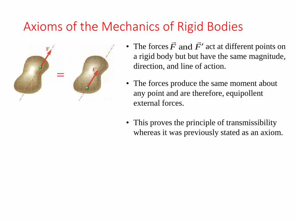
Axioms of the Mechanics of Rigid Bodies
• The forces act at different points on
a rigid body but but have the same magnitude,
direction, and line of action.
FF and
• The forces produce the same moment about
any point and are therefore, equipollent
external forces.
• This proves the principle of transmissibility
whereas it was previously stated as an axiom.
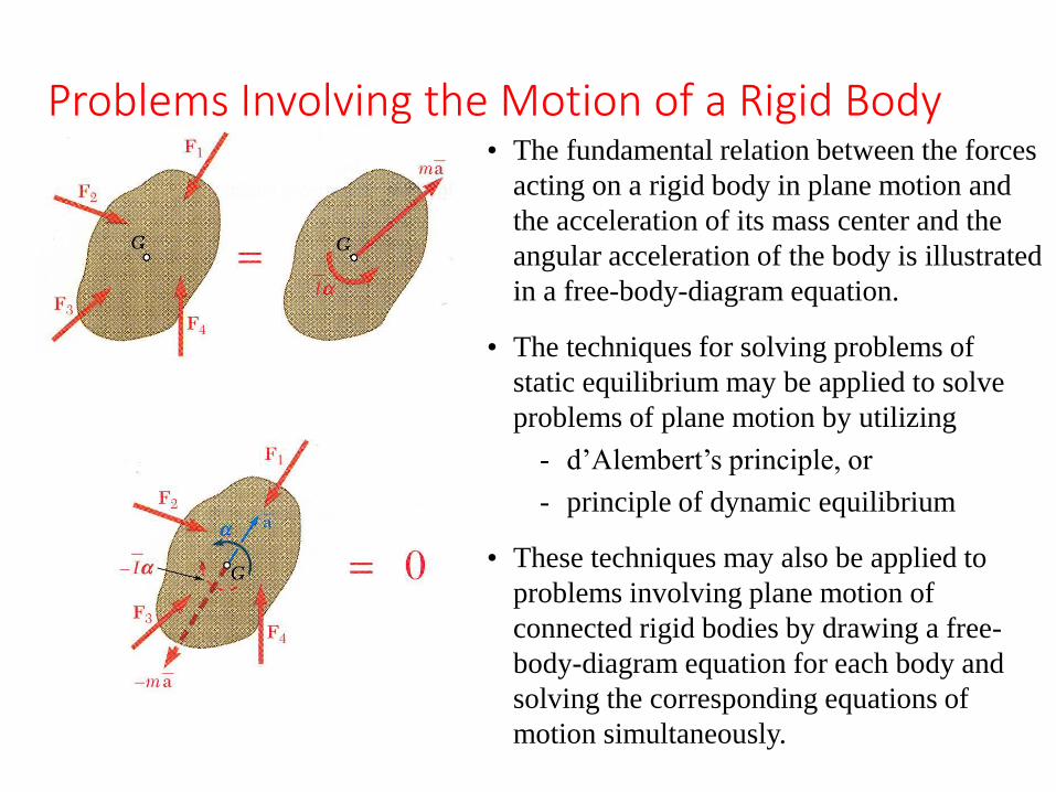
Problems Involving the Motion of a Rigid Body• The fundamental relation between the forces
acting on a rigid body in plane motion and
the acceleration of its mass center and the
angular acceleration of the body is illustrated
in a free-body-diagram equation.
• The techniques for solving problems of
static equilibrium may be applied to solve
problems of plane motion by utilizing
- d’Alembert’s principle, or
- principle of dynamic equilibrium
• These techniques may also be applied to
problems involving plane motion of
connected rigid bodies by drawing a free-
body-diagram equation for each body and
solving the corresponding equations of
motion simultaneously.

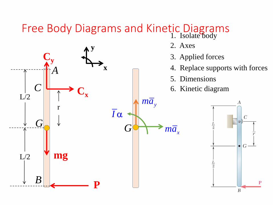
Free Body Diagrams and Kinetic Diagrams
Draw the FBD and KD for
the bar AB of mass m. A
known force P is applied at
the bottom of the bar.
Free Body Diagrams and Kinetic Diagrams
P
L/2
L/2
r
A
Cx
Cy
mg
1. Isolate body
2. Axes
3. Applied forces
4. Replace supports with forces
5. Dimensions
6. Kinetic diagram
GG
xma
yma
I
C
B
x
y

Free Body Diagrams and Kinetic Diagrams
The ladder AB slides down
the wall as shown. The wall
and floor are both rough.
Draw the FBD and KD for
the ladder.

Free Body Diagrams and Kinetic Diagrams
FA
W
NA
FB
NB
xma
yma
I
1. Isolate body
2. Axes
3. Applied forces
4. Replace supports with forces
5. Dimensions
6. Kinetic diagram
=
x
y
q

Sample Problem 16.1
At a forward speed of 30 ft/s, the truck
brakes were applied, causing the wheels
to stop rotating. It was observed that the
truck to skidded to a stop in 20 ft.
Determine the magnitude of the normal
reaction and the friction force at each
wheel as the truck skidded to a stop.
SOLUTION:
• Calculate the acceleration during the
skidding stop by assuming uniform
acceleration.
• Apply the three corresponding scalar
equations to solve for the unknown
normal wheel forces at the front and rear
and the coefficient of friction between
the wheels and road surface.
• Draw the free-body-diagram equation
expressing the equivalence of the
external and effective forces.

Sample Problem 16.1
ft20s
ft300 xv
SOLUTION:
• Calculate the acceleration during the skidding stop
by assuming uniform acceleration.
ft202s
ft300
2
2
020
2
a
xxavv
s
ft5.22a
• Draw a free-body-diagram equation expressing the
equivalence of the external and inertial terms.
• Apply the corresponding scalar equations.
0 WNN BA
effyy FF
699.02.32
5.22
g
a
agWW
NN
amFF
k
k
BAk
BA
effxx FF

Sample Problem 16.1
WNWN BA 350.0
WNN Arear 350.021
21 WNrear 175.0
WNN Vfront 650.021
21 WN front 325.0
WNF rearkrear 175.0690.0 WFrear 122.0
WNF frontkfront 325.0690.0
WFfront 227.0.0
• Apply the corresponding scalar equations.
WN
g
aWa
g
WWN
amNW
B
B
B
650.0
4512
4512
1
ft4ft12ft5
effAA MM

Sample Problem 16.2
The thin plate of mass 8 kg is held in
place as shown.
Neglecting the mass of the links,
determine immediately after the wire
has been cut (a) the acceleration of the
plate, and (b) the force in each link.
SOLUTION:
• Note that after the wire is cut, all
particles of the plate move along parallel
circular paths of radius 150 mm. The
plate is in curvilinear translation.
• Draw the free-body-diagram equation
expressing the equivalence of the
external and effective forces.
• Resolve into scalar component equations
parallel and perpendicular to the path of
the mass center.
• Solve the component equations and the
moment equation for the unknown
acceleration and link forces.

Sample Problem 16.2SOLUTION:
• Note that after the wire is cut, all particles of the
plate move along parallel circular paths of radius
150 mm. The plate is in curvilinear translation.
• Draw the free-body-diagram equation expressing
the equivalence of the external and effective
forces.
• Resolve the diagram equation into components
parallel and perpendicular to the path of the mass
center.
efftt FF
30cos
30cos
mg
amW
30cosm/s81.9 2a
2sm50.8a 60o
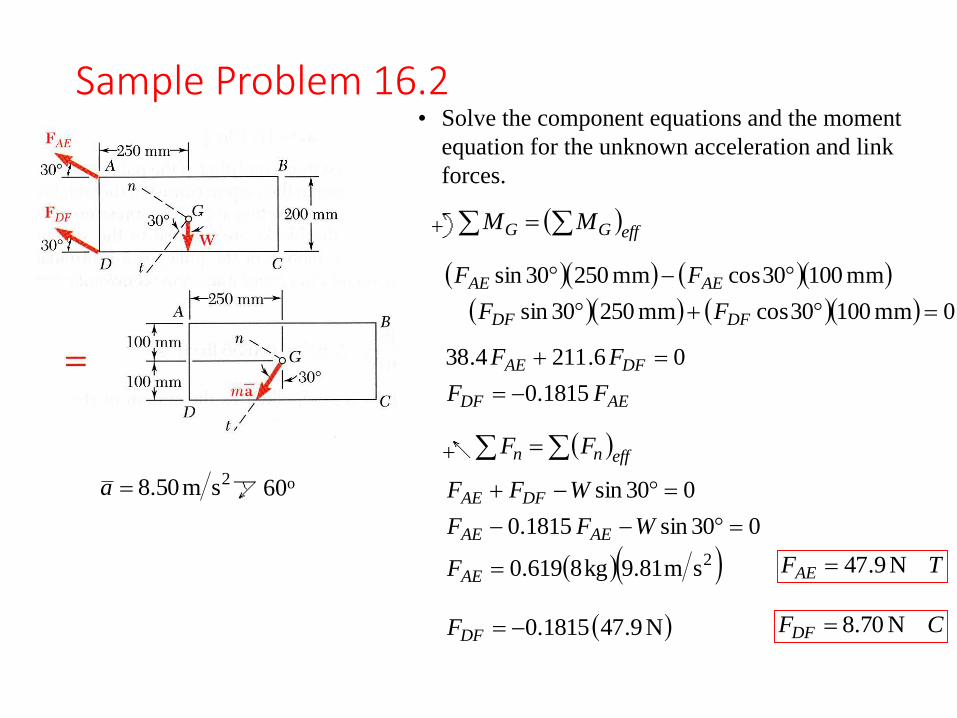
Sample Problem 16.2
2sm50.8a 60o
• Solve the component equations and the moment
equation for the unknown acceleration and link
forces.
effGG MM
0mm10030cosmm25030sin
mm10030cosmm25030sin
DFDF
AEAE
FF
FF
AEDF
DFAE
FF
FF
1815.0
06.2114.38
effnn FF
2sm81.9kg8619.0
030sin1815.0
030sin
AE
AEAE
DFAE
F
WFF
WFF
TFAE N9.47
N9.471815.0DFF CFDF N70.8

Sample Problem 16.3
A pulley weighing 12 lb and having a
radius of gyration of 8 in. is connected to
two blocks as shown.
Assuming no axle friction, determine the
angular acceleration of the pulley and the
acceleration of each block.
SOLUTION:
• Determine the direction of rotation by
evaluating the net moment on the
pulley due to the two blocks.
• Relate the acceleration of the blocks to
the angular acceleration of the pulley.
• Draw the free-body-diagram equation
expressing the equivalence of the
external and effective forces on the
complete pulley plus blocks system.
• Solve the corresponding moment
equation for the pulley angular
acceleration.
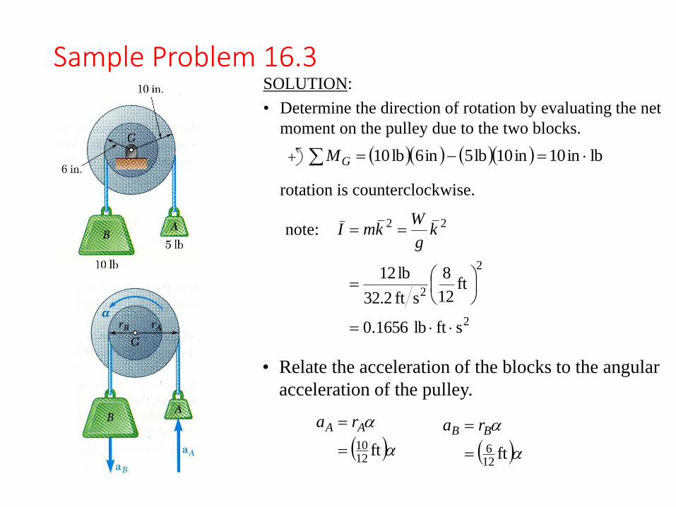
Sample Problem 16.3
• Relate the acceleration of the blocks to the angular
acceleration of the pulley.
ft1210
AA ra
ft126
BB ra
2
2
2
22
sftlb1656.0
ft12
8
sft32.2
lb12
kg
WkmInote:
SOLUTION:
• Determine the direction of rotation by evaluating the net
moment on the pulley due to the two blocks.
lbin10in10lb5in6lb10 GM
rotation is counterclockwise.

Sample Problem 16.3• Draw the free-body-diagram equation expressing the
equivalence of the external and effective forces on the
complete pulley and blocks system.
2
126
2
1210
2
sft
sft
sftlb1656.0
B
A
a
a
I
effGG MM
1210
1210
2.325
126
126
2.3210
1210
126
1210
126
1210
126
1656.0510
ftftftlb5ftlb10
AABB amamI
• Solve the corresponding moment equation for the pulley
angular acceleration.
2srad374.2
2
126 srad2.374ft
BB ra2sft187.1Ba
2
1210 srad2.374ft
AA ra
2sft978.1Aa
Then,
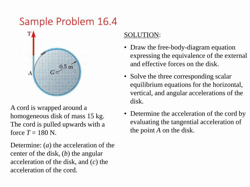
Sample Problem 16.4
A cord is wrapped around a
homogeneous disk of mass 15 kg.
The cord is pulled upwards with a
force T = 180 N.
Determine: (a) the acceleration of the
center of the disk, (b) the angular
acceleration of the disk, and (c) the
acceleration of the cord.
SOLUTION:
• Draw the free-body-diagram equation
expressing the equivalence of the external
and effective forces on the disk.
• Solve the three corresponding scalar
equilibrium equations for the horizontal,
vertical, and angular accelerations of the
disk.
• Determine the acceleration of the cord by
evaluating the tangential acceleration of
the point A on the disk.

Sample Problem 16.4SOLUTION:
• Draw the free-body-diagram equation expressing the
equivalence of the external and effective forces on the
disk.
effyy FF
kg15
sm81.9kg15-N180 2
m
WTa
amWT
y
y
2sm19.2ya
effGG MM
m5.0kg15
N18022
2
21
mr
T
mrITr
2srad0.48
effxx FF
xam0 0xa
• Solve the three scalar equilibrium equations.
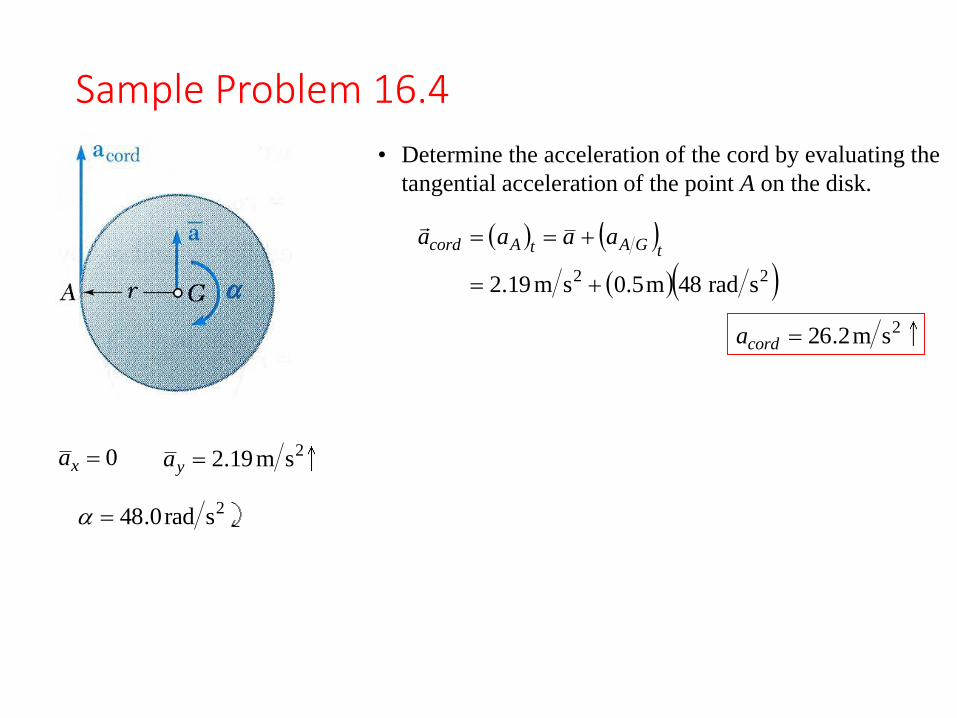
Sample Problem 16.4
2sm19.2ya
2srad0.48
0xa
• Determine the acceleration of the cord by evaluating the
tangential acceleration of the point A on the disk.
22 srad48m5.0sm19.2
tGAtAcord aaaa
2sm2.26corda

Prob # 16.5
A uniform rod BC of mass 4 kg is
connected to a collar A by a
250-mm cord AB. Neglecting the
mass of the collar and cord,
determine
(a) the smallest constant
acceleration aA for which the
cord and the rod will lie in a
straight line,
(b) the corresponding
tension in the cord.

Prob# 16.14
A uniform rectangular plate has a
mass of 5 kg and is held in position by
three ropes as shown. Knowing that
θ= 30°, determine,
immediately after rope CF has been
cut,
(a) the acceleration of the plate,
(b) the tension in ropes AD and BE.
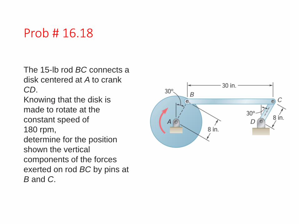
Prob # 16.18
The 15-lb rod BC connects a
disk centered at A to crank
CD.
Knowing that the disk is
made to rotate at the
constant speed of
180 rpm,
determine for the position
shown the vertical
components of the forces
exerted on rod BC by pins at
B and C.

Prob # 16.38
Disks A and B are bolted together,
and cylinders D and E are
attached to separate cords wrapped
on the disks. A single cord
passes over disks B and C. Disk A
weighs 20 lb and disks B and
C each weigh 12 lb. Knowing that
the system is released from rest
and that no slipping occurs between
the cords and the disks,
determine the acceleration
(a) of cylinder D,
(b) of cylinder E