powerpoint -l6 slides
TRANSCRIPT
1
6 - 1© P. Raatikainen Switching Technology / 2003
Switch Fabrics
Switching Technology S38.165http://www.netlab.hut.fi/opetus/s38165
6 - 2© P. Raatikainen Switching Technology / 2003
Switch fabrics
• Multi-point switching• Self-routing networks
• Sorting n etworks• Fabric implementation technologies• Fault tolerance and reliability
2
6 - 3© P. Raatikainen Switching Technology / 2003
Sorting networks
• Types of blocking
• Internal blocking
• Output blocking
• Head of line blocking
• Sorting to remove internal blocking
• Resolving output conflicts
• Easing of HOL blocking
6 - 4© P. Raatikainen Switching Technology / 2003
Internal blocking
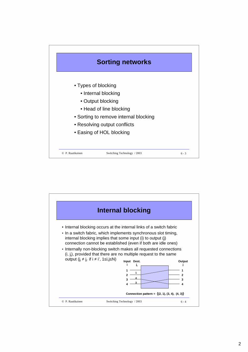
• Internal blocking occurs at the internal links of a switch fabric
• In a switch fabric, which implements synchronous slot timing,internal blocking implies that some input (i) to output (j)connection cannot be established (even if both are idle ones)
• Internally non-blocking switch makes all requested connections(i, ji), provided that there are no multiple request to the sameoutput (ji ≠ ji’ if i ≠ i’, 1≤i,j≤N)
1
2
Inputi
3
4
1
2
Outputj
3
4
Connection pattern = {(2, 1), (3, 4), (4, 3)}
Dest.ji
1
4
3
3
6 - 5© P. Raatikainen Switching Technology / 2003
Output blocking
• Internally non-blocking switch can block at an output of a switchfabric due to conflicting requests, i.e., ji = ji’ for some i ≠ i’
• When output conflict occurs, switch should connect one of theconflicting inputs to requested output => output conflict resolution
• Major distinction between a circuit and packet switching node• a packet switching node must solve output conflicts per time-slot (time-
slots are not assigned beforehand)
• a circuit switching node solvespossible output conflicts andassigns a time-slot for entireduration of a connectionbeforehand
1
2
Inputi
3
4
1
2
Outputj
3
4
Dest.ji
1
4
3
3
Conflicting output request
6 - 6© P. Raatikainen Switching Technology / 2003
Head of line (HOL) blocking
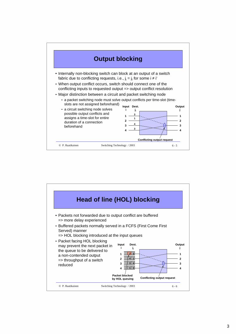
• Packets not forwarded due to output conflict are buffered=> more delay experienced
• Buffered packets normally served in a FCFS (First Come FirstServed) manner=> HOL blocking introduced at the input queues
• Packet facing HOL blockingmay prevent the next packet inthe queue to be delivered toa non-contended output=> throughput of a switchreduced
1
2
Inputi
3
4
1
2
Outputj
3
4
Dest.ji
14
43
31
32
Conflicting output requestPacket blocked by HOL queuing
4
6 - 7© P. Raatikainen Switching Technology / 2003
Sorting to remove internal blocking
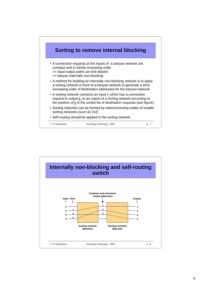
• If connection requests at the inputs of a banyan network arecompact and in strictly increasing order=> input-output paths are link-disjoint=> banyan internally non-blocking
• A method for building an internally non-blocking network is to applya sorting network in front of a banyan network to generate a strictincreasing order of destination addresses for the banyan network
• A sorting network connects an input i, which has a connectionrequest to output ji, to an output of a sorting network according tothe position of ji in the sorted list of destination requests (see figure)
• Sorting networks can be formed by interconnecting nodes of smallersorting networks (such as 2x2)
• Self-routing should be applied in the sorting network
6 - 8© P. Raatikainen Switching Technology / 2003
Internally non-blocking and self-routingswitch
1
2
Inputi
3
4
Outputj
4
Dest.ji
1
4
3
1
2
3
1
3
4
Sorting network(Batcher)
Routing network(Banyan)
Compact and monotone output addresses
5
6 - 9© P. Raatikainen Switching Technology / 2003
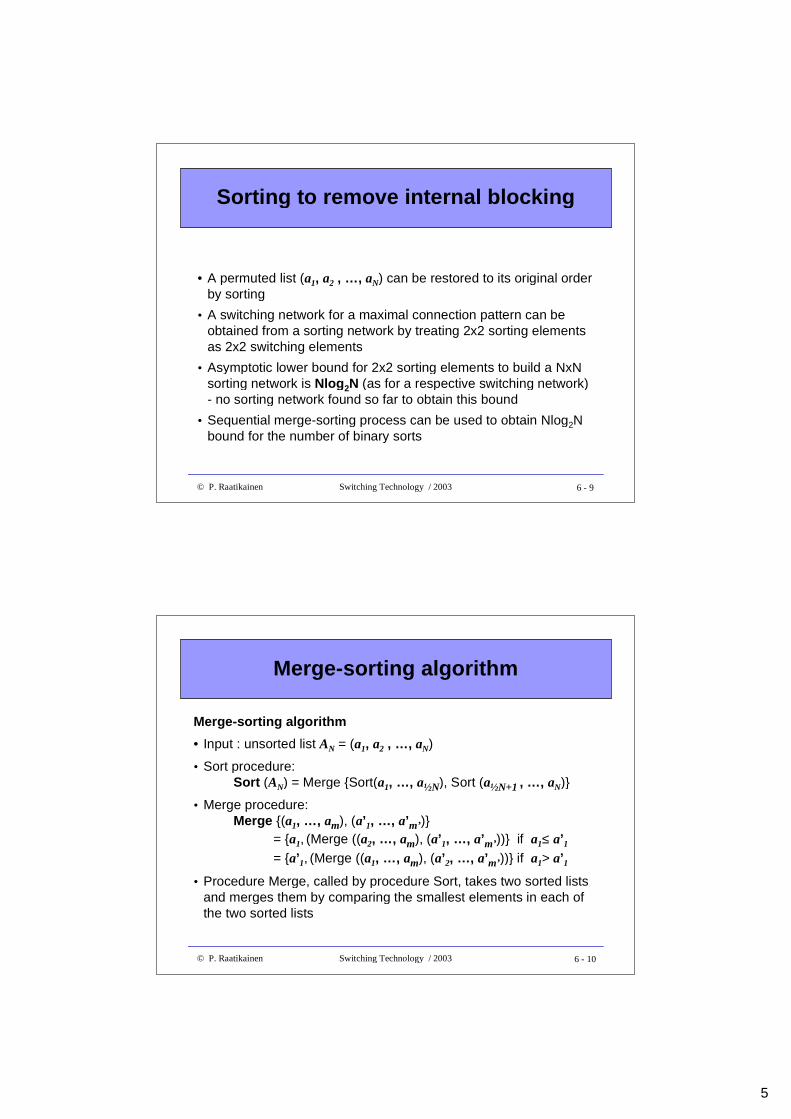
Sorting to remove internal block ing
• A permuted list (a1, a2 , …, aN) can be restored to its original orderby sorting
• A switching network for a maximal connection pattern can beobtained from a sorting network by treating 2x2 sorting elementsas 2x2 switching elements
• Asymptotic lower bound for 2x2 sorting elements to build a NxNsorting network is Nlog 2N (as for a respective switching network)- no sorting network found so far to obtain this bound
• Sequential merge-sorting process can be used to obtain Nlog2Nbound for the number of binary sorts
6 - 10© P. Raatikainen Switching Technology / 2003
Merge-sorting algorithm
Merge-sorting algorithm
• Input : unsorted list AN = (a1, a2 , …, aN)
• Sort procedure:Sort (AN) = Merge {Sort(a1, …, a½N), Sort (a½N+1 , …, aN)}
• Merge procedure:Merge {(a1, …, am), (a’1, …, a’m’)}
= {a1, (Merge ((a2, …, am), (a’1, …, a’m’))} if a1≤ a’1= {a’1, (Merge ((a1, …, am), (a’2, …, a’m’))} if a1> a’1
• Procedure Merge, called by procedure Sort, takes two sorted listsand merges them by comparing the smallest elements in each ofthe two sorted lists
6
6 - 11© P. Raatikainen Switching Technology / 2003
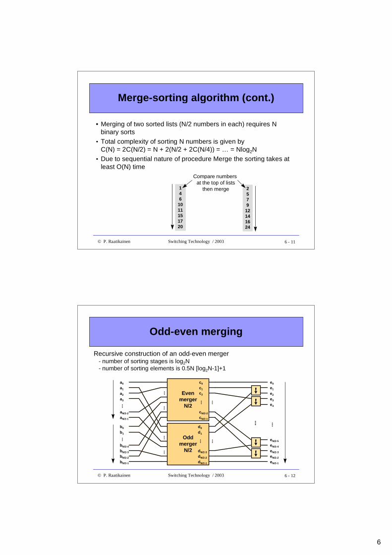
Merge-sorting algorithm (cont.)
• Merging of two sorted lists (N/2 numbers in each) requires Nbinary sorts
• Total complexity of sorting N numbers is given byC(N) = 2C(N/2) = N + 2(N/2 + 2C(N/4)) = … = Nlog2N
• Due to sequential nature of procedure Merge the sorting takes atleast O(N) time
146
1011151720
2579
12141624
Compare numbers at the top of lists
then merge
6 - 12© P. Raatikainen Switching Technology / 2003
Odd-even merging
a0
a1
a2
a3
aN/2-2
aN/2-1
...
b0
b1
bN/2-4
bN/2-3
bN/2-2
bN/2-1
...
e0
e1
eN/2-4
eN/2-3
eN/2-2
eN/2-1
...
e2
e3
e4
eN/2-5
Evenmerger
N/2
Oddmerger
N/2
......
......
......
d0
d1
dN/2-3
dN/2-2
dN/2-1
...
➙➙
➙➙
c0
c1
cN/2-2
cN/2-1
...
c2
...
Recursive construction of an odd-even merger- number of sorting stages is log2N- number of sorting elements is 0.5N [log2N-1]+1
7
6 - 13© P. Raatikainen Switching Technology / 2003
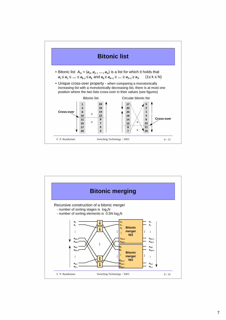
Bitonic list
• Bitonic list AN = (a1, a2 , …, aN) is a list for which it holds thata1 ≤ a2 ≤ … ≤ ak-1 ≤ ak and ak ≥ ak+1 ≥ … ≥ aN-1 ≥ aN (1≤ k ≤ N)
• Unique cross-over property - when comparing a monotonicallyincreasing list with a monotonically decreasing list, there is at most oneposition where the two lists cross-over in their values (see figures)
146
1011151720
241614129752
<
>
Bitonic list
Cross-over
17202416141297
52146
101115<
>
Circular bitonic list
Cross-over
6 - 14© P. Raatikainen Switching Technology / 2003
Bitonic merging
a0
a1
aN/2-2
aN/2-1
...
aN/2
aN/2+1
aN-2
aN-1
...
Bitonicmerger
N/2
Bitonicmerger
N/2
......
......
d0
d1
dN/2-3
dN/2-2
dN/2-1
...
c0
c1
cN/2-2
cN/2-1
...
c2
➙➙
➙➙
...
e0
e1
eN/2-2
eN/2-1
...
eN/2
eN/2+1
eN-2
eN-1
...
Recursive construction of a bitonic merger- number of sorting stages is log2N- number of sorting elements is 0.5N log2N
8
6 - 15© P. Raatikainen Switching Technology / 2003
Sorting by merging
a0
a1
aN/2-2
aN/2-1
...
aN/2
aN/2+1
aN-2
aN-1
...
...
➙
➙
...
e0
eN-1
➙
➙
...
MergerN
MergerN/2
MergerN/4
MergerN/4
➙
➙
➙
MergerN/2
MergerN/4
MergerN/4
➙
➙
➙
...
...
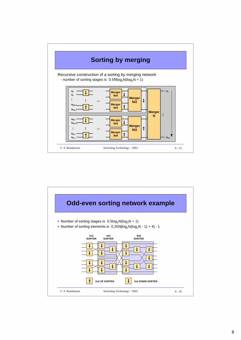
Recursive construction of a sorting by merging network- number of sorting stages is 0.5Nlog2N(log2N + 1)
6 - 16© P. Raatikainen Switching Technology / 2003
Odd-even sorting network example
➙ 2x2 UP SORTER
➙
2x2 DOWN SORTER
2x2SORTER
4x4SORTER
➙➙
➙
➙➙ ➙
➙
➙
➙➙ ➙
➙
➙
➙➙
➙
➙➙
➙
8x8SORTER
• Number of sorting stages is 0.5log2N(log2N + 1)• Number of sorting elements is 0.25N[log2N(log2N - 1) + 4] - 1
9
6 - 17© P. Raatikainen Switching Technology / 2003
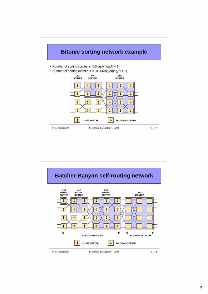
Bitonic sorting network example
➙ 2x2 UP SORTER
➙
2x2 DOWN SORTER
2x2SORTER
➙
➙
➙
➙ ➙ ➙
➙ ➙
➙
➙
➙
➙
➙
➙
➙
➙
➙
➙
➙
➙ ➙ ➙
➙ ➙
4x4SORTER
8x8SORTER
• Number of sorting stages is 0.5log2N(log2N + 1)• Number of sorting elements is 0.25Nlog2N(log2N + 1)
6 - 18© P. Raatikainen Switching Technology / 2003
Batcher-Banyan self-routing network
➙ 2x2 UP SORTER
➙
2x2 DOWN SORTER
2x2BITONICSORTER
➙
➙
➙
➙ ➙ ➙
➙ ➙
➙
➙
➙
➙
➙
➙
➙
➙
➙
➙
➙
➙ ➙ ➙
➙ ➙
4x4BITONICSORTER
8x8BITONICSORTER
8x8ROUTER
SORTING NETWORK ROUTING NETWORK
10
6 - 19© P. Raatikainen Switching Technology / 2003
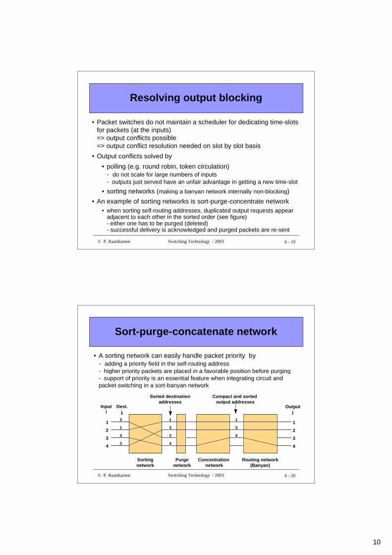
Resolving output blocking
• Packet switches do not maintain a scheduler for dedicating time-slotsfor packets (at the inputs)=> output conflicts possible=> output conflict resolution needed on slot by slot basis
• Output conflicts solved by
• polling (e.g. round robin, token circulation)- do not scale for large numbers of inputs- outputs just served have an unfair advantage in getting a new time-slot
• sorting networks (making a banyan network internally non-blocking)
• An example of sorting networks is sort-purge-concentrate network• when sorting self-routing addresses, duplicated output requests appear
adjacent to each other in the sorted order (see figure)- either one has to be purged (deleted)- successful delivery is acknowledged and purged packets are re-sent
6 - 20© P. Raatikainen Switching Technology / 2003
Sort-purge-concatenate network
1
2
Inputi
3
4
Outputj
4
Dest.ji
1
2
3
Sortingnetwork
Concentration network
Compact and sorted output addresses
1
3
4
1
3
3
4
3
1
4
3
Purgenetwork
Routing network(Banyan)
Sorted destinationaddresses
• A sorting network can easily handle packet priority by- adding a priority field in the self-routing address- higher priority packets are placed in a favorable position before purging- support of priority is an essential feature when integrating circuit andpacket switching in a sort-banyan network
11
6 - 21© P. Raatikainen Switching Technology / 2003
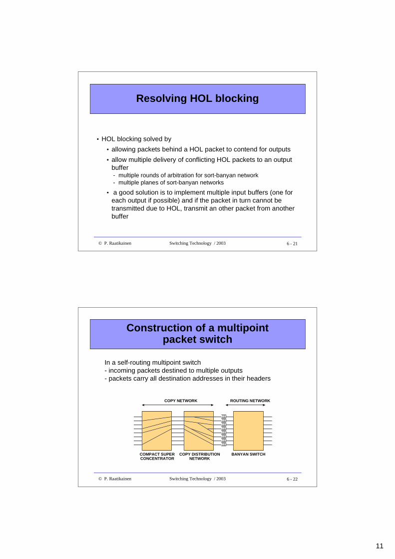
Resolving HOL blocking
• HOL blocking solved by
• allowing packets behind a HOL packet to contend for outputs
• allow multiple delivery of conflicting HOL packets to an outputbuffer - multiple rounds of arbitration for sort-banyan network - multiple planes of sort-banyan networks
• a good solution is to implement multiple input buffers (one foreach output if possible) and if the packet in turn cannot betransmitted due to HOL, transmit an other packet from anotherbuffer
6 - 22© P. Raatikainen Switching Technology / 2003
Construction of a multipointpacket switch
In a self-routing multipoint switch- incoming packets destined to multiple outputs- packets carry all destination addresses in their headers
COMPACT SUPERCONCENTRATOR
COPY DISTRIBUTIONNETWORK
BANYAN SWITCH
COPY NETWORK ROUTING NETWORK
12
6 - 23© P. Raatikainen Switching Technology / 2003
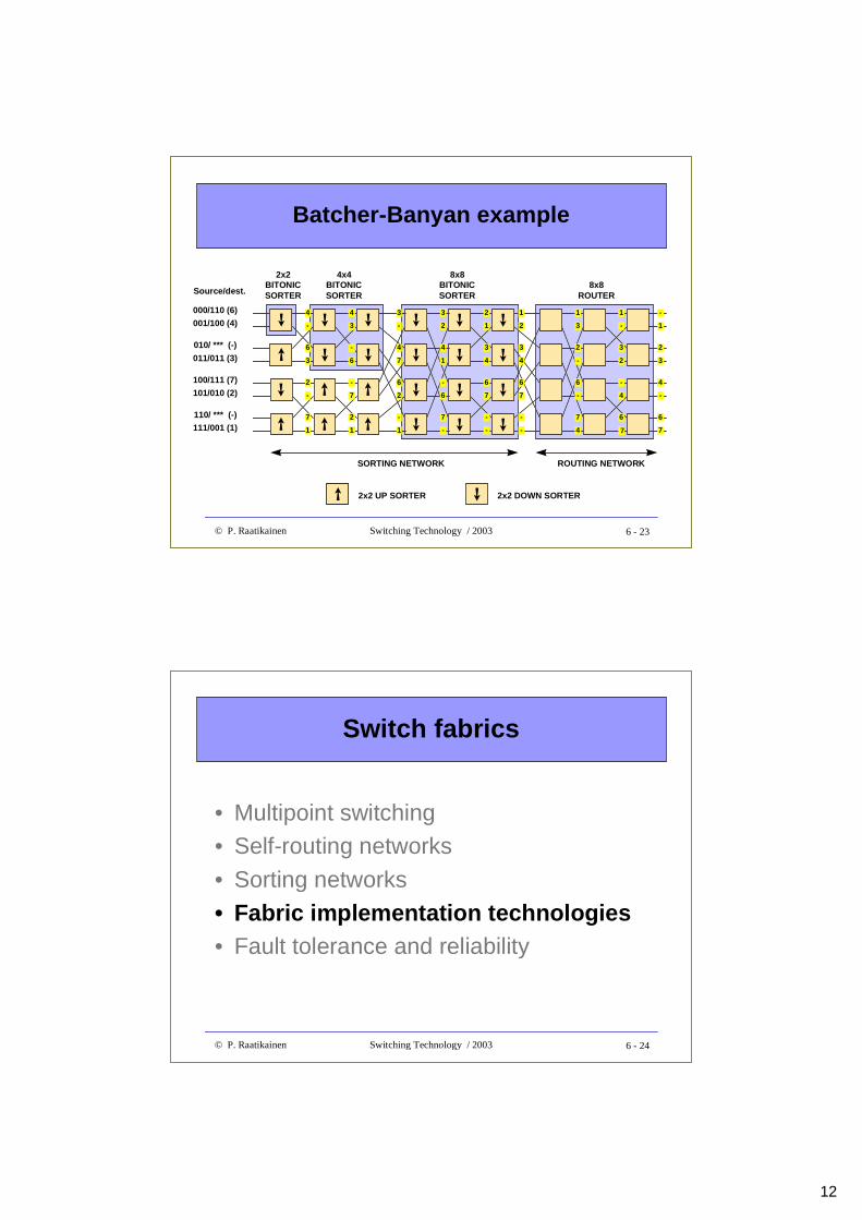
Batcher-Banyan example
➙ 2x2 UP SORTER
➙
2x2 DOWN SORTER
2x2BITONICSORTER
➙
➙
➙
➙ ➙ ➙
➙ ➙
➙
➙
➙
➙
➙
➙
➙
➙
➙
➙
➙
➙ ➙ ➙
➙ ➙
4x4BITONICSORTER
8x8BITONICSORTER
8x8ROUTER
SORTING NETWORK ROUTING NETWORK
000/110 (6)
001/100 (4)
010/ *** (-)
011/011 (3)
100/111 (7)
101/010 (2)
110/ *** (-)
111/001 (1)
Source/dest.
6
4
3
-
7
2
1
-
-
4
6
3
2
-
1
7
4
3
7
-
-
6
1
2
4
3
1
2
7
-
-
6
3
2
4
1
-
6
-
7
3
1
4
2
-
6
-
7
2
1
-
3
7
6
4
-
3
1
2
-
6
-
7
4
2
-
3
1
6
4
7
-
6 - 24© P. Raatikainen Switching Technology / 2003
Switch fabrics
• Multipoint switching• Self-routing networks
• Sorting networks• Fabric implementation technologies• Fault tolerance and reliability
13
6 - 25© P. Raatikainen Switching Technology / 2003
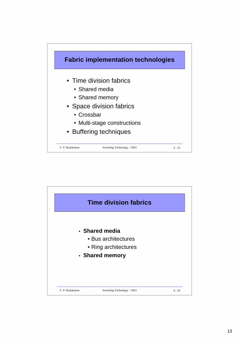
Fabric implementation technologies
• Time division fabrics• Shared media• Shared memory
• Space division fabrics• Crossbar• Multi-stage constructions
• Buffering techniques
6 - 26© P. Raatikainen Switching Technology / 2003
Time division fabrics
• Shared media• Bus architectures• Ring architectures
• Shared memory
14
6 - 27© P. Raatikainen Switching Technology / 2003
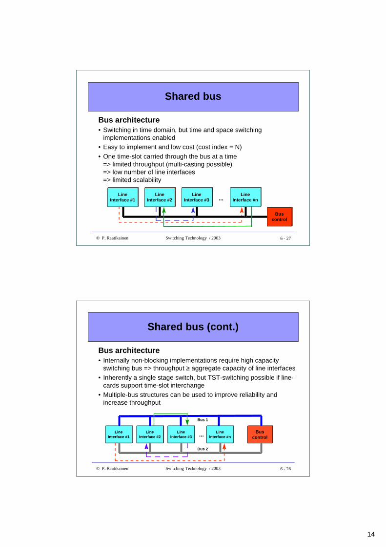
Shared bus
Bus architecture• Switching in time domain, but time and space switching
implementations enabled• Easy to implement and low cost (cost index = N)
• One time-slot carried through the bus at a time=> limited throughput (multi-casting possible)=> low number of line interfaces=> limited scalability
Buscontrol
LineInterface #2
LineInterface #3
LineInterface #n...
LineInterface #1
6 - 28© P. Raatikainen Switching Technology / 2003
Shared bus (cont.)
Bus architecture• Internally non-blocking implementations require high capacity
switching bus => throughput ≥ aggregate capacity of line interfaces
• Inherently a single stage switch, but TST-switching possible if line-cards support time-slot interchange
• Multiple-bus structures can be used to improve reliability andincrease throughput
LineInterface #2
LineInterface #3
LineInterface #n...Line
Interface #1Bus
control
Bus 2
Bus 1
15
6 - 29© P. Raatikainen Switching Technology / 2003
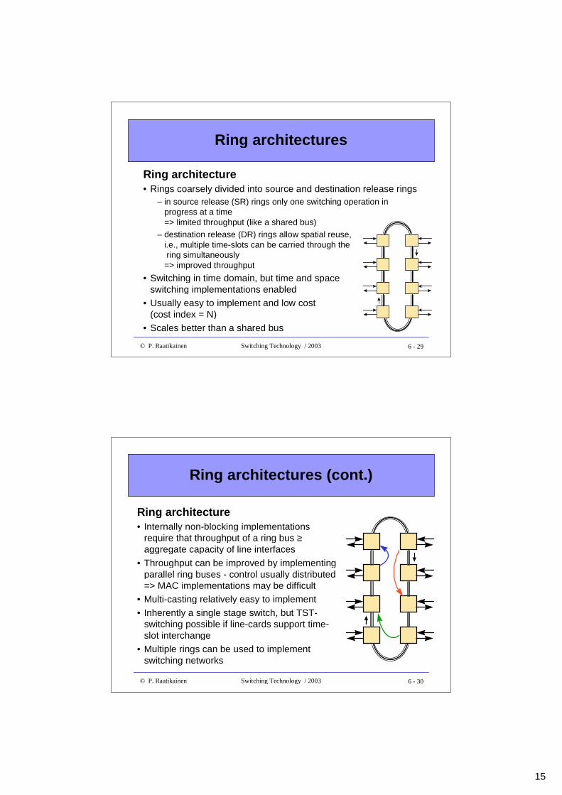
Ring architectures
Ring architecture• Rings coarsely divided into source and destination release rings
– in source release (SR) rings only one switching operation inprogress at a time=> limited throughput (like a shared bus)
– destination release (DR) rings allow spatial reuse,i.e., multiple time-slots can be carried through the ring simultaneously=> improved throughput
• Switching in time domain, but time and spaceswitching implementations enabled
• Usually easy to implement and low cost(cost index = N)
• Scales better than a shared bus
6 - 30© P. Raatikainen Switching Technology / 2003
Ring architectures (cont.)
Ring architecture• Internally non-blocking implementations
require that throughput of a ring bus ≥aggregate capacity of line interfaces
• Throughput can be improved by implementingparallel ring buses - control usually distributed=> MAC implementations may be difficult
• Multi-casting relatively easy to implement
• Inherently a single stage switch, but TST-switching possible if line-cards support time-slot interchange
• Multiple rings can be used to implementswitching networks
16
6 - 31© P. Raatikainen Switching Technology / 2003
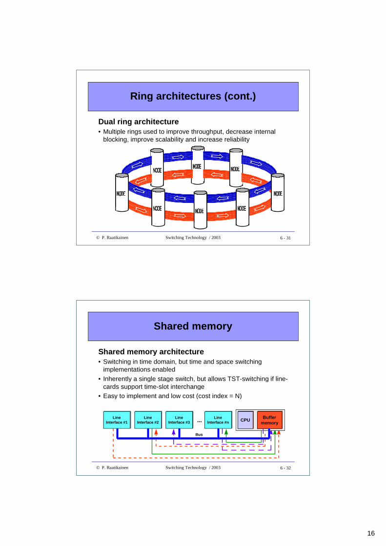
Ring architectures (cont.)
Dual ring architecture• Multiple rings used to improve throughput, decrease internal
blocking, improve scalability and increase reliability
6 - 32© P. Raatikainen Switching Technology / 2003
Shared memory
Shared memory architecture• Switching in time domain, but time and space switching
implementations enabled
• Inherently a single stage switch, but allows TST-switching if line-cards support time-slot interchange
• Easy to implement and low cost (cost index = N)
Buffermemory
CPU
Bus
LineInterface #2
LineInterface #3
LineInterface #n...Line
Interface #1
17
6 - 33© P. Raatikainen Switching Technology / 2003
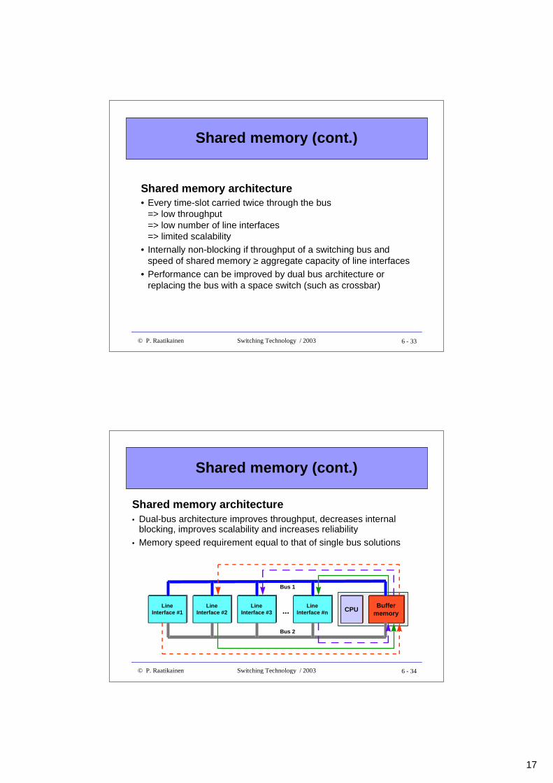
Shared memory (cont.)
Shared memory architecture• Every time-slot carried twice through the bus
=> low throughput=> low number of line interfaces=> limited scalability
• Internally non-blocking if throughput of a switching bus andspeed of shared memory ≥ aggregate capacity of line interfaces
• Performance can be improved by dual bus architecture orreplacing the bus with a space switch (such as crossbar)
6 - 34© P. Raatikainen Switching Technology / 2003
Shared memory (cont.)
Shared memory architecture• Dual-bus architecture improves throughput, decreases internal
blocking, improves scalability and increases reliability• Memory speed requirement equal to that of single bus solutions
LineInterface #2
LineInterface #3
LineInterface #n...
LineInterface #1
Buffermemory
CPU
Bus 1
Bus 2
18
6 - 35© P. Raatikainen Switching Technology / 2003
Dimensioning example
A shared memory architecture, which uses a shared bus toconnect line interfaces to the memory, is used to implement aswitching equipment. The bus is 32 bits wide and bus clock is 150MHz. Three clock cycles are needed to transfer a 32 bit wordthrough the bus and 20 % of the bus capacity is used for otherthan switching purposes. How many E1 interfaces can besupported by the switch ? What is the required memory speed ?
Solution:
If the bus transfers an eight bit time-slot (of a 64 kbit/s PDH channel)across the bus at a time, a single bus solution can transfer0.8x(150/3) Mbytes/s = 40 Mbytes/s
6 - 36© P. Raatikainen Switching Technology / 2003
Dimensioning example (cont.)
Solution (cont.):In a single bus solution, half of the bus capacity (20 Mbytes/s) is usedfor storing time-slots to memory and another half for reading time-slotsfrom memory => memory speed requirement is 1/(20 Mbytes/s) = 50 ns => during a 125 µs period (= duration of an E1 frame) the busswitches 125x20 bytes = 2500 time-slots and the number of supportedE1 links is 2500/32 ≈ 78
Throughput of the switching system can be increased by adding a 32 bitreceive-register to the shared switch memory block, which enables to transfer4 time-slots (in parallel) through the bus at a time. By doing so, the throughputof the bus gets four fold and the number of supported E1 links increases to312. Time-slots are still written one by one to the switch memory, and thus thememory speed requirement is 12.5 ns.
19
6 - 37© P. Raatikainen Switching Technology / 2003
Space division fabrics
• Crossbar• Multi-stage constructions
6 - 38© P. Raatikainen Switching Technology / 2003
Crossbar
Crossbar architecture• Inherently a space division switch
• Allows to build TST-switches if interfaces implement time-slotinterchange functionality
• Hard to implement large switches due to complicated controlschemes=> high cost (cost index = N2)
• Commercial high-speed NxN crossbar components enablemodular and relatively inexpensive fabric constructions, but stillcontrol of the switch is a problem
20
6 - 39© P. Raatikainen Switching Technology / 2003
Crossbar (cont.)
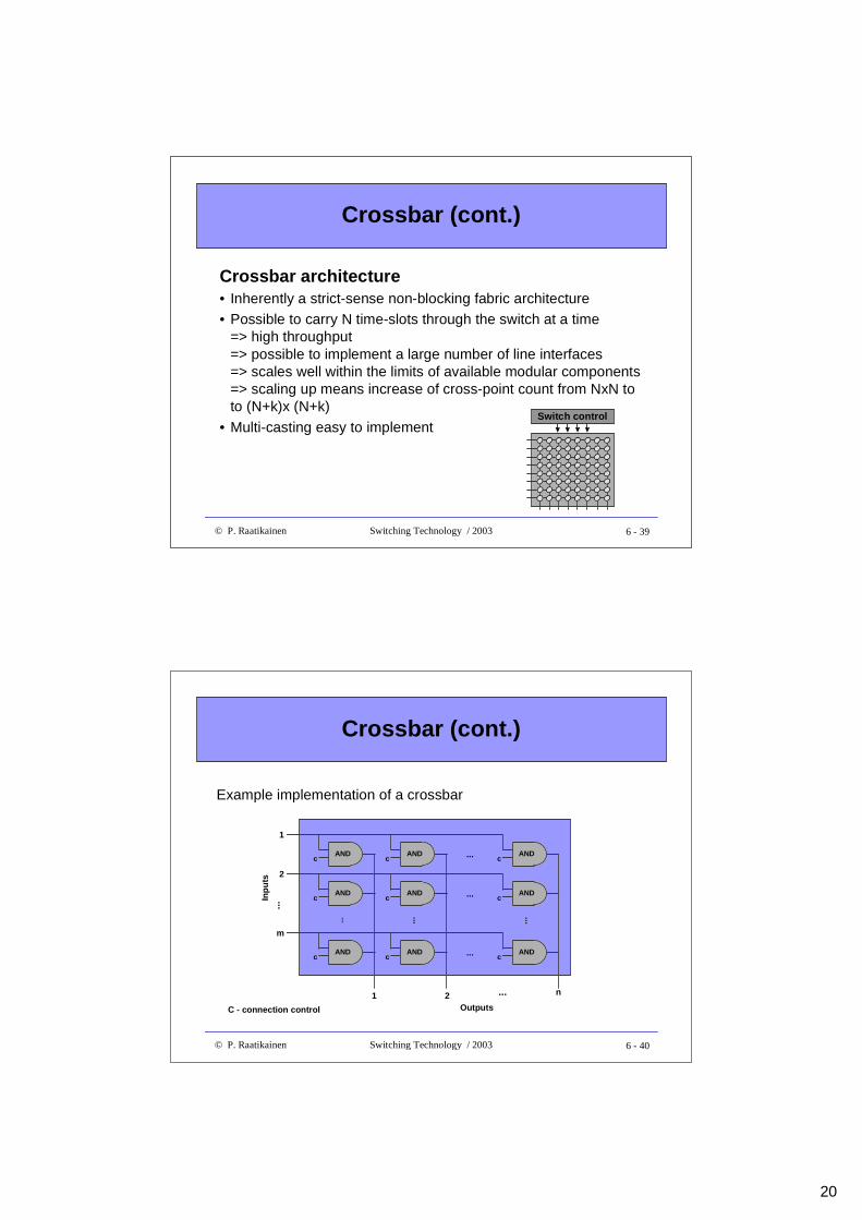
Crossbar architecture• Inherently a strict-sense non-blocking fabric architecture• Possible to carry N time-slots through the switch at a time
=> high throughput=> possible to implement a large number of line interfaces=> scales well within the limits of available modular components=> scaling up means increase of cross-point count from NxN toto (N+k)x (N+k)
• Multi-casting easy to implementSwitch control
6 - 40© P. Raatikainen Switching Technology / 2003
Crossbar (cont.)
C - connection control
Example implementation of a crossbar
c c c
c c c
c c c
AND
AND
AND
AND
AND
AND
AND
AND
AND
...
...
...
... ... ...
1
2
m
...
1 2 n...
Outputs
Inp
uts
21
6 - 41© P. Raatikainen Switching Technology / 2003
Crossbar (cont.)
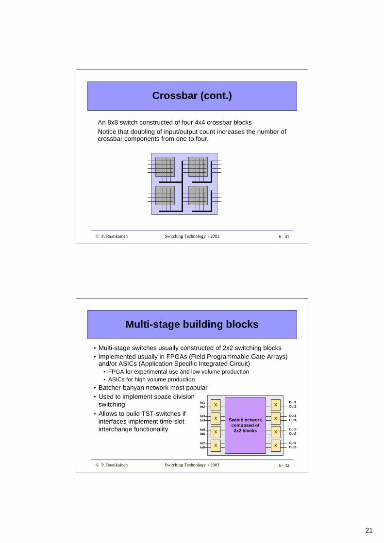
An 8x8 switch constructed of four 4x4 crossbar blocks
Notice that doubling of input/output count increases the number ofcrossbar components from one to four.
6 - 42© P. Raatikainen Switching Technology / 2003
Multi-stage building blocks
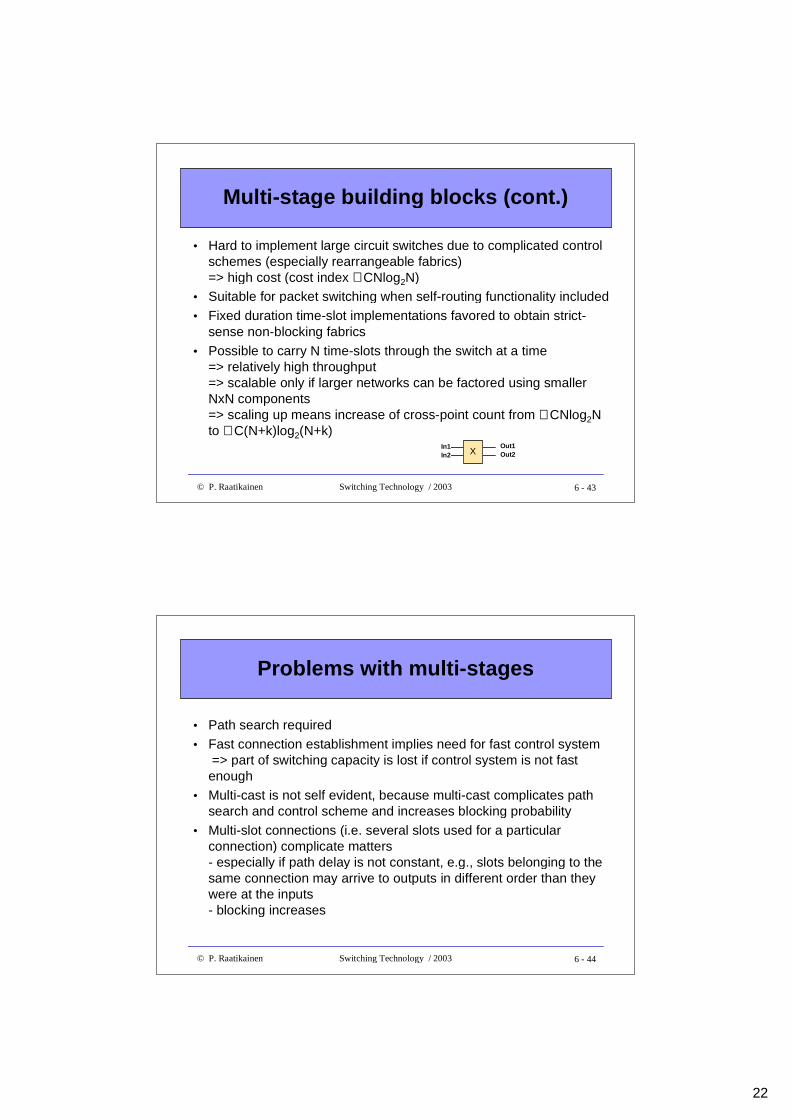
• Multi-stage switches usually constructed of 2x2 switching blocks• Implemented usually in FPGAs (Field Programmable Gate Arrays)
and/or ASICs (Application Specific Integrated Circuit)• FPGA for experimental use and low volume production• ASICs for high volume production
• Batcher-banyan network most popular• Used to implement space division
switching
• Allows to build TST-switches ifinterfaces implement time-slotinterchange functionality
XIn1In2
Out1Out2
XIn3In4
Out1Out2
XIn5In6
Out1Out2
XIn7In8
Out1Out2
XIn1In2
Out1Out2
XIn1In2
Out3Out4
XIn1In2
Out5Out6
XIn1In2
Out7Out8
Switch networkcomposed of2x2 blocks
22
6 - 43© P. Raatikainen Switching Technology / 2003
Multi-stage building blocks (cont.)
• Hard to implement large circuit switches due to complicated controlschemes (especially rearrangeable fabrics)=> high cost (cost index ∼∼ CNlog2N)
• Suitable for packet switching when self-routing functionality included
• Fixed duration time-slot implementations favored to obtain strict-sense non-blocking fabrics
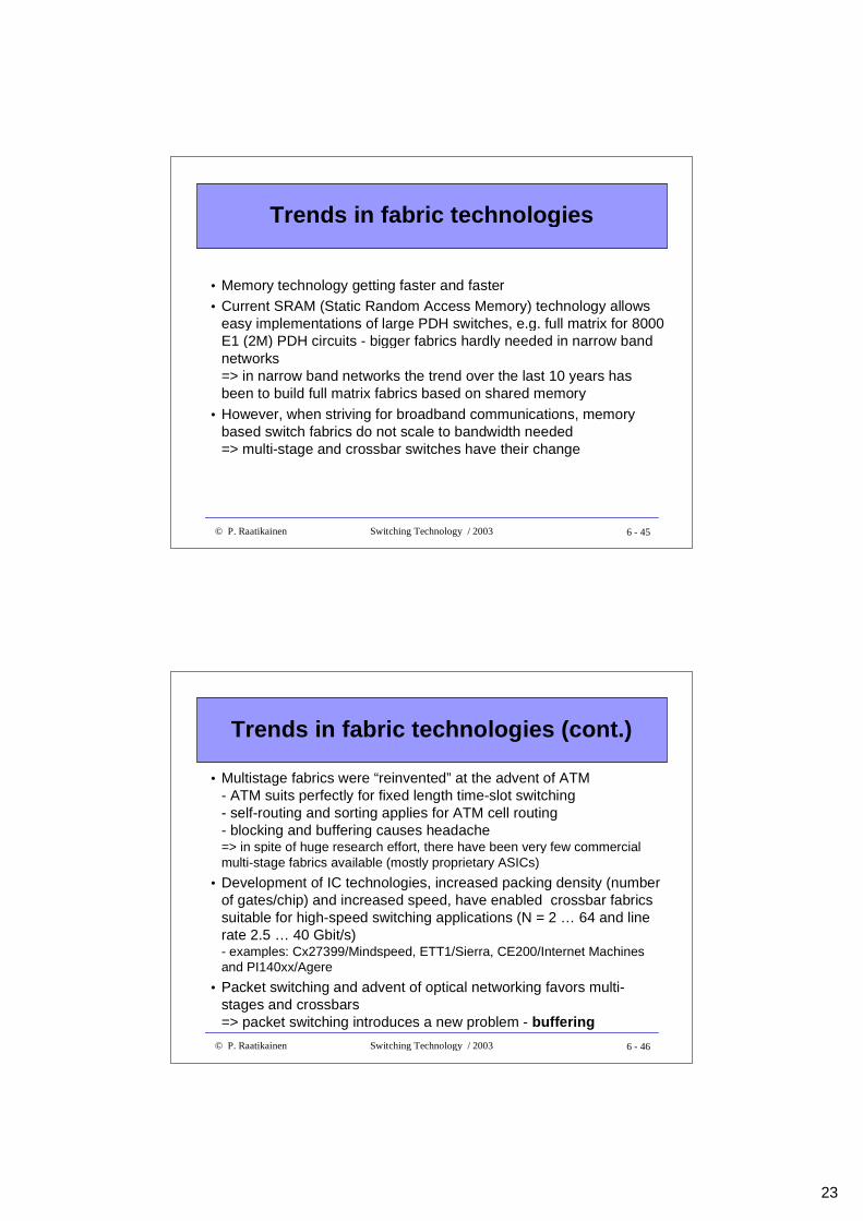
• Possible to carry N time-slots through the switch at a time=> relatively high throughput=> scalable only if larger networks can be factored using smallerNxN components=> scaling up means increase of cross-point count from ∼∼ CNlog2Nto ∼∼ C(N+k)log2(N+k)
XIn1In2
Out1Out2
6 - 44© P. Raatikainen Switching Technology / 2003
Problems with multi-stages
• Path search required
• Fast connection establishment implies need for fast control system => part of switching capacity is lost if control system is not fastenough
• Multi-cast is not self evident, because multi-cast complicates pathsearch and control scheme and increases blocking probability
• Multi-slot connections (i.e. several slots used for a particularconnection) complicate matters- especially if path delay is not constant, e.g., slots belonging to thesame connection may arrive to outputs in different order than theywere at the inputs- blocking increases
23
6 - 45© P. Raatikainen Switching Technology / 2003
Trends in fabric technologies
• Memory technology getting faster and faster
• Current SRAM (Static Random Access Memory) technology allowseasy implementations of large PDH switches, e.g. full matrix for 8000E1 (2M) PDH circuits - bigger fabrics hardly needed in narrow bandnetworks=> in narrow band networks the trend over the last 10 years hasbeen to build full matrix fabrics based on shared memory
• However, when striving for broadband communications, memorybased switch fabrics do not scale to bandwidth needed=> multi-stage and crossbar switches have their change
6 - 46© P. Raatikainen Switching Technology / 2003
Trends in fabric technologies (cont.)
• Multistage fabrics were “reinvented” at the advent of ATM- ATM suits perfectly for fixed length time-slot switching- self-routing and sorting applies for ATM cell routing- blocking and buffering causes headache=> in spite of huge research effort, there have been very few commercialmulti-stage fabrics available (mostly proprietary ASICs)
• Development of IC technologies, increased packing density (numberof gates/chip) and increased speed, have enabled crossbar fabricssuitable for high-speed switching applications (N = 2 … 64 and linerate 2.5 … 40 Gbit/s)- examples: Cx27399/Mindspeed, ETT1/Sierra, CE200/Internet Machinesand PI140xx/Agere
• Packet switching and advent of optical networking favors multi-stages and crossbars=> packet switching introduces a new problem - buffering
24
6 - 47© P. Raatikainen Switching Technology / 2003
Technological tradeoffs in switch fabricdesign
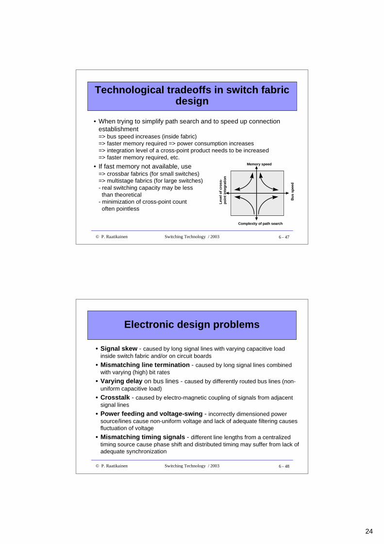
• When trying to simplify path search and to speed up connectionestablishment=> bus speed increases (inside fabric)=> faster memory required => power consumption increases=> integration level of a cross-point product needs to be increased=> faster memory required, etc.
• If fast memory not available, use=> crossbar fabrics (for small switches)=> multistage fabrics (for large switches)- real switching capacity may be less than theoretical- minimization of cross-point count often pointless
Lev
el o
f cr
oss
-p
oin
t in
teg
rati
on
Memory speed
Bu
s sp
eed
Complexity of path search
6 - 48© P. Raatikainen Switching Technology / 2003
Electronic design problems
• Signal skew - caused by long signal lines with varying capacitive loadinside switch fabric and/or on circuit boards
• Mismatching line termination - caused by long signal lines combinedwith varying (high) bit rates
• Varying delay on bus lines - caused by differently routed bus lines (non-uniform capacitive load)
• Crosstalk - caused by electro-magnetic coupling of signals from adjacentsignal lines
• Power feeding and voltage-swing - incorrectly dimensioned powersource/lines cause non-uniform voltage and lack of adequate filtering causesfluctuation of voltage
• Mismatching timing signals - different line lengths from a centralizedtiming source cause phase shift and distributed timing may suffer from lack ofadequate synchronization
25
6 - 49© P. Raatikainen Switching Technology / 2003
Some design limitations
• Speed of available components vs. required wire speed and slottime interval
• Component packing density and power consumption vs. heatingproblem
• Maximum practical fan-out vs. required size of fabric
• Required bus length inside switch fabric- long buses decrease internal speed of fabric- diagnostics get difficult
• IPR policy- whether company wants to use special components or moregeneral all-purpose components
6 - 50© P. Raatikainen Switching Technology / 2003
Design optimization example
• An NxN switch fabric is to be designed and there are three alternativecrossbar components a, b and c available- a is an NaxNa fabric component- b is an NbxNb fabric component- c is an NcxNc fabric componentand Na<Nb<Nc≤N
• Component a has entered the market at time ta, b at time tb and c at time tc• Product development starts at tpd and the switch product should come in the
market at tm. Components are expected to be available when the productdevelopment starts => ta < tb < tc ≤ tpd < tm
• Price of a component develops with time and is generally given byP(t)=Cf(t) + D, where Cf(t) is a time dependent and D a constant part ofcomponent’s price
• Question: Which one of the three components to choose for constructing anNxN switch fabric ?
26
6 - 51© P. Raatikainen Switching Technology / 2003
Design optimization example (cont.)
• As an example, let’s assume that price of each component is a function oftime and is given by P(t)=Ce-t/T+ D ,where C, D and T are component specific constants=> Pa(t)=Cae-t/Ta+ Da , Pb(t)=Cbe-t/Tb+ Db and Pc(t)=Cce-t/Tc+ Dc
• Number of alternative crossbar components needed to build an NxN switch=> Ka = ceil[N/Na]
2, Kb = ceil[N/Nb]2 , Kc = ceil[N/Nc]
2
• Alternative component costs as a function of time t=> Pa(t)=Cae-(t- ta)/Ta+ Ca
=> Pb(t)=Cbe-(t- tb)/Tb+ Cb
=> Pc(t)=Cce-(t- tc)/Tc+ Cc
• These functions can be used to draw price development curves to makecomparisons
6 - 52© P. Raatikainen Switching Technology / 2003
Design optimization example (cont.)
Numerical example:• Let N = 64, Na = 16, Nb = 32, Nc = 64, Ta = Tb = Tc = 3 time units (years),
Ca = 20,Cb = 50, Cc = 100 and Da = 10, Db = 20, Dc = 40 price units (euros)
• Product development period is assumed to be 1 time unit (year) andtb = ta +1.5, tc = ta +3, tm = ta +4 => tpd = ta + 3
• Choosing that tpd = to = 0 => ta = t + 3, tb = t +1.5, tc = t, tm = t -1 (t ≥ tpd = 0 )
• Number of components needed Ka = 16, Kb = 4, Kc = 1
• Switch fabric component cost functions
=> Pa(t)=16[20e-(t+3)/3 + 10]=> Pb(t)=4[50e-(t+1.5)/3 + 20]=> Pc(t)=100e-(t)/3 + 40
27
6 - 53© P. Raatikainen Switching Technology / 2003
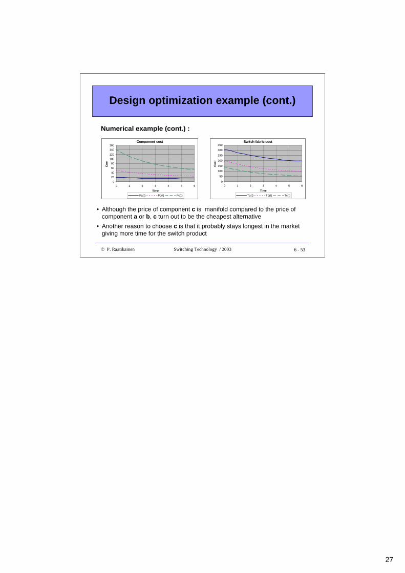
Design optimization example (cont.)
• Although the price of component c is manifold compared to the price ofcomponent a or b, c turn out to be the cheapest alternative
• Another reason to choose c is that it probably stays longest in the marketgiving more time for the switch product
Numerical example (cont.) :
Component cost
0
20
40
60
80
100
120
140
160
0 1 2 3 4 5 6
Time
Co
st
Pa(t) Pb(t) Pc(t)
Switch fabric cost
0
50
100
150
200
250
300
350
0 1 2 3 4 5 6
Time
Co
st
Ta(t) Tb(t) Tc(t)