pp 07-cap1 ing - hydraquip.co.uk · movement 1 1 >movement guided cylinders non standard...
TRANSCRIPT


General Index
5 > Vacuum
5 / 2 Suction Pads
5 / 4 Ejectors
5 / 8 Accessories
5 / 9 Filters
4 > Connection
3 > Treatment
3 / 2 Modular FRL Units - 3/8, 1/2, 3/4 and 13 / 14 Modular FRL Units - 1/43 / 23 Pressure Regulators3 / 25 FRL Units - 1/8 and 1/43 / 27 Pressure Gauges and Accessories for Air Treatment
4 / 2 Technical Data4 / 3 Super-Rapid Fittings4 / 15 Rapid Fittings 4 / 19 Compression Fittings4 / 20 Fittings Accessories4 / 29 Quick-Release Couplings4 / 30 Air Brake Fittings4 / 33 NPT Fittings
2 > Control
2 / 2 Technical Data2 / 11 Directly and Indirectly Operated Solenoid Valves2 / 23 Solenoid Valves / Pneumatic Valves 2 / 48 Solenoid DIN connectors2 / 52 Valve Islands2 / 76 Mechanical and Manual Valves2 / 85 Logic Valves2 / 86 Automatic Valves2 / 88 Flow Control Valves 2 / 94 Pressure Switches and Vacuum Switches2 / 98 Silencers2 / 99 Proportional Technology
1 / 2 International Standard Cylinders1 / 17 Compact Cylinders1 / 20 Guided Cylinders1 / 23 Non Standard Cylinders1 / 28 Rotary Cylinders1 / 31 Grippers1 / 33 Rodless Cylinders1 / 38 Stainless Steel Cylinders1 / 44 Proximity Switches1 / 46 Additional Cylinder Accessories
1 > Movement

6 > Ball Valves & Non Return Valves
6 / 2 Brass Two-Way Ball Valves (Economy)
6 / 4 Brass Two-Way Ball Valves (Premium)
6 / 6 Stainless Steel Two-Way Ball Valves
6 / 7 Eurofly Valves
6 / 8 Direct Mount Ball Valves (for actuation)
6 / 10 Exhausting Brass Ball Valves
6 / 12 Brass Three-Way Ball Valves
6 / 13 Non-Return Valves
7 > Process Valves & Actuation
7 / 2 Butterfly Valves
7 / 4 Actuated Two-Way Ball Valves
7 / 8 Actuated Three-Way Ball Valves
7 / 10 Knife Gate Valves
7 / 12 Other Actuated Valves
7 / 15 Industrial Solenoid Valves
7 / 24 NAMUR Valves
8 > Hydraulic Couplings
8 / 2 Flat Face Couplings - ISO 16028
8 / 7 Quick Release Couplings - ISO A Norm
8 / 14 Quick Release Couplings - ISO B Norm
9 > Hydraulic Valves and Accessories
9 / 2 Hydraulic Ball Valves
9 / 6 Accessories
10 > Tubing
10 / 2 Nylon
10 / 5 PVC Hose
10 / 7 Pneumatic Polyurethane Tubing
10 / 8 PTFE Tubing
10 / 8 Accessories
a / 2 Information on the use of Camozzi Productsa / 3 Qualitya / 5 Systems, Assembly and Design Servicesa / 7 ATEX Certified Productsa / 9 Pneumatic Symbolsa / 13 Technical Information about Products
a > Appendix
a

MOVEM
ENT
1 1 > Movement
Guided Cylinders
Non Standard Cylinders
1 / 23 Series 14Compact Mini-Cylinders
1 / 24 Series 27 RoundlineCylinders and Accessories
1 / 26 Series 42Cylinders and Accessories
1 / 20 Series QCT and QCBCylinders with Integrated Guide
1 / 21 Series QCTF - QCBF Slide Units
1 / 22 Series QX Twin Rod Cylinders
International Standard Cylinders
1 / 2 Series 16, 24 and 25Mini-Cylinders and AccessoriesCETOP RP-52-PDIN/ISO 6432
1 / 4 Series 40 Cylinders and AccessoriesISO 15552DIN/ISO 6431 / VDMA 24562
1 / 6 Series 41 Cylinders Aluminium Profile andAccessoriesDIN/ISO 6431 / VDMA 24562
1 / 8 Series 60Cylinders and AccessoriesISO 15552DIN/ISO 6431 / VDMA 24562
1 / 10 Series 61Cylinders - Aluminium Profile and AccessoriesISO 15552 DIN/ISO 6431 / VDMA 24562
1 / 12 Series 6PF Cylinders - Aluminium Profile and AccessoriesISO 15552 DIN/ISO 6431 / VDMA 24562
1 / 14 Series 32Compact Magnetic CylindersISO 21287
1 / 15 Series 32Compact Magnetic Cylinders(Tandem and Multi-PositionVersions)ISO 21287
1 / 16 Series 45 Guide Units
Compact Cylinders
1 / 17 Series QNShort-Stroke Cylinders
1 / 17 Series QP - QPRShort-Stroke Cylinders
1 / 18 Series 31 CompactMagnetic Cylinders
1 / 19 Series 31 Compact MagneticCylinders (Tandem and Multi-Position Versions)
1
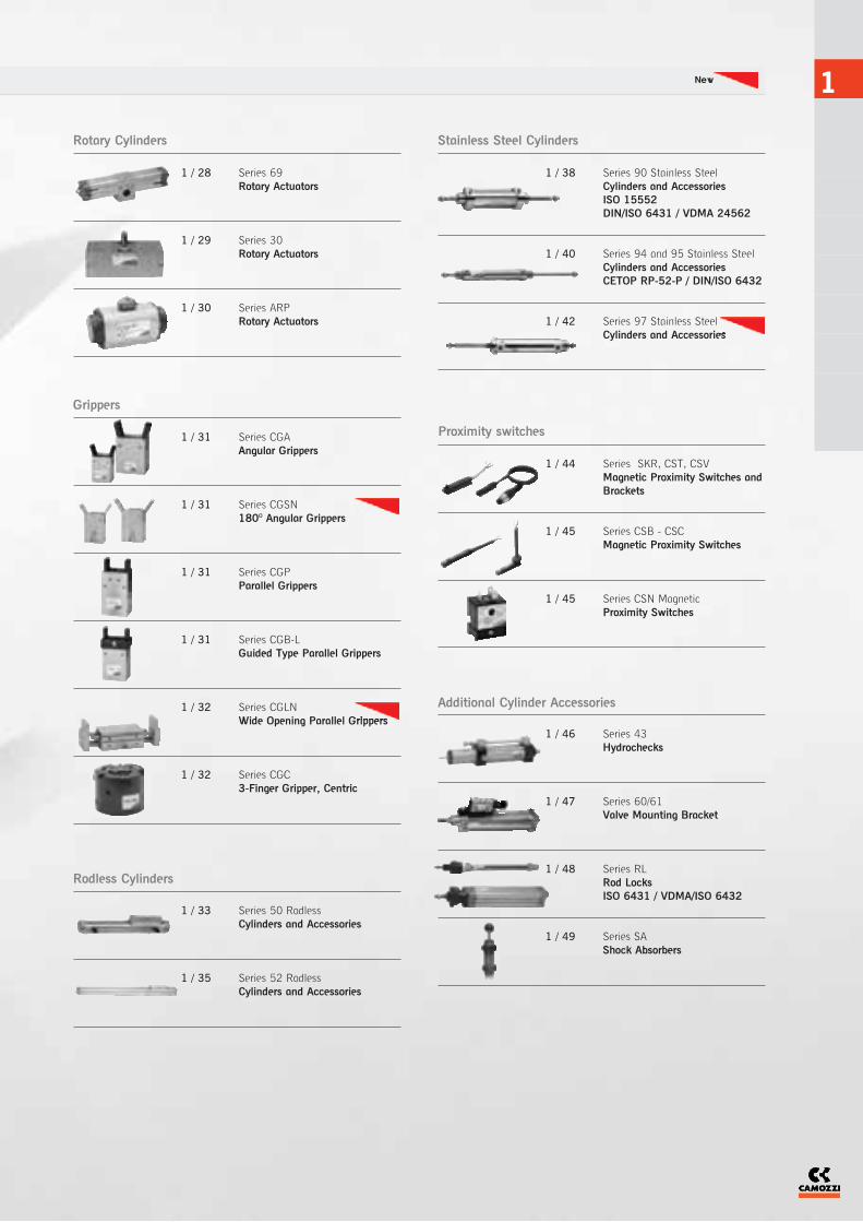
Rotary Cylinders Stainless Steel Cylinders
Rodless Cylinders
Proximity switches
Additional Cylinder Accessories
1 / 46 Series 43Hydrochecks
1 / 47 Series 60/61Valve Mounting Bracket
1 / 48 Series RLRod LocksISO 6431 / VDMA/ISO 6432
1 / 49 Series SAShock Absorbers
1 / 44 Series SKR, CST, CSVMagnetic Proximity Switches andBrackets
1 / 45 Series CSB - CSC Magnetic Proximity Switches
1 / 45 Series CSN MagneticProximity Switches
1 / 38 Series 90 Stainless SteelCylinders and AccessoriesISO 15552DIN/ISO 6431 / VDMA 24562
1 / 40 Series 94 and 95 Stainless SteelCylinders and AccessoriesCETOP RP-52-P / DIN/ISO 6432
1 / 42 Series 97 Stainless SteelCylinders and Accessories
1 / 28 Series 69Rotary Actuators
1 / 29 Series 30 Rotary Actuators
1 / 30 Series ARPRotary Actuators
1 / 33 Series 50 Rodless Cylinders and Accessories
1 / 35 Series 52 Rodless Cylinders and Accessories
Grippers
1 / 31 Series CGA Angular Grippers
1 / 31 Series CGSN 180O Angular Grippers
1 / 31 Series CGPParallel Grippers
1 / 31 Series CGB-L Guided Type Parallel Grippers
1 / 32 Series CGLN Wide Opening Parallel Grippers
1 / 32 Series CGC3-Finger Gripper, Centric
New

Single-acting and double-acting - Cetop RP52-P DIN/ISO 6432Series 16: Ø8, Ø10, Ø12Series 24: Ø16, Ø20, Ø25 - magneticSeries 25: Ø16, Ø20, Ø25 - magnetic cushioned
The Camozzi ISO mini-cylinder range is available in three different versions to suit the requirements of the design engineer.
Series 16, 24 and 25 Mini-Cylinders
MOVEM
ENT
1
The company reserves the right to vary models and dimensions without notice.Products designed for industrial applications. General terms and conditions for sale are available on www.camozzi.co.uk
MOVEMENT > Series 16, 24 and 25 UK SHORT FORM CATALOGUE > Release 8.6
1
2
Technical DataType of ConstructionPiston cylinder - rolled construction,single-acting, double-acting, through-rod. Magnetic or non-magneticMediaCompressed air (filtered), with orwithout lubricationOperating Pressure1 bar to 10 bar (double-acting)2 bar to 10 bar (single-acting)Operating Temperature0oC to +80oC (with dry air -20oC to +80oC)MaterialsCylinder Barrel: Stainless steelEnd Blocks: Cast aluminiumNose Seals: PolyurethaneOther Seals: NBRPiston Rod: Stainless steelPiston Rod Lock Nut: Zinc-platedsteelNose Nut: Zinc-plated steelCushioningSeries 16 and 24 - End of stroke buffersSeries 25 - End of stroke buffers withadjustable pneumatic cushioningBore Sizes8, 10, 12, 16, 20, 25mmStroke LengthsStandard - see table Non-standard - on requestSpeedMin 10mm/sec. (no load)Max 1000mm/sec. (no load)ConnectionsØ8, Ø10, Ø12, Ø16 - M5Ø20, Ø25 - 1/8MountingsComprehensive range of ISOmounting brackets - see page 1/3Cylinder GuidesSee page 1/16Cylinder Piston Force and AirConsumptionRefer to appendix pages 17-20Cylinder Breakdown ServiceSame day breakdown service on allstandard and non-standard cylinders Additional OptionsAdjustable cushioning - series 25 onlyCylinder sensors - see page 1/44Piston rod accessories - see page 1/3Viton seals - Non-standard availableonly on requestRod Lock Units - see page 1/48Special RequestsFor assistance, contact our technicaloffice or your local Camozzi distributor.
Series 16 16 16 24 24 24 25 25 25
Ø8 Ø10 Ø12 Ø16 Ø20 Ø25 Ø16 Ø20 Ø25
Standard Stroke
10 ■ ✖ ■ ✖ ■ ✖ ■ ✖ ■ ✖ ■ ✖ ■ ■ ■
25 ■ ✖ ■ ✖ ■ ✖ ■ ✖ ■ ✖ ■ ✖ ■ ■ ■
40 ■ ✖ ■ ✖ ■ ✖ ■ ✖ ■ ✖ ■ ✖ ■ ■ ■
50 ■ ✖ ■ ✖ ■ ✖ ■ ✖ ■ ✖ ■ ✖ ■ ■ ■
80 ■ ■ ■ ■ ■ ■ ■ ■ ■
100 ■ ■ ■ ■ ■ ■ ■ ■ ■
125 ■ ■ ■ ■ ■ ■ ■ ■ ■
160 ■ ■ ■ ■ ■ ■ ■ ■ ■
200 ■ ■ ■ ■ ■ ■ ■ ■ ■
250 ■ ■ ■ ■ ■ ■ ■
300 ■ ■ ■ ■ ■ ■ ■
320 ■ ■ ■ ■ ■ ■
400 ■ ■ ■ ■ ■ ■
500 ■ ■ ■ ■ ■ ■
CODING EXAMPLE
SERIES:16 = non-magnetic24 = magnetic25 = magnetic adjustable cushioning
VERSION:N =standard
OPERATION:1 = single-acting (front spring) 2 = double-acting 3 = double-acting (through rod)7 = single-acting (through rod)
MATERIALS:A = rolled stainless steel AISI 303
rod, stainless steel AISI 304tube, anodized AL end-blocks
BORE:8, 10, 12, 16, 20, 25mm
STROKE: (see table)
SPECIAL: to be specifiedV = Rod Seal Viton
NOTE: All cylinders are supplied complete with nose nut and nut for rod. The accessories are supplied separately.
Double-acting and Single-acting (through rod and non-standard strokes available on request)
■ Double-acting✖ Single-acting
STANDARD STROKES FOR MINICYLINDERS SERIES 16, 24 AND 25
24 N 2 A 16 A 100 -
24
N
2
A
16
A
100
-
SAME
DAY
TYPE OF BRACKET:A = standard (screw with ring
+ lock nut for rod)RL= cylinder with rod lock Ø20 - Ø25

1
See full catalogue or CD rom for all dimensions.For technical advice contact our sales office or your local Camozzi distributor.
UK SHORT FORM CATALOGUE > Release 8.6 MOVEMENT > Series 16, 24 and 25
1
3
Rod Fork End
Ø
G-8-10 8-10
G-12-16 12-16
G-20 20
G-25-32 25
Foot Mounts (pair)
Ø
B-8-10 8-10
B-12-16 12-16
B-20-25 20-25
Front/Rear Flange Mount
Ø
E-8-10 8-10
E-12-16 12-16
E-20-25 20-25
Rear Trunnion Bracket
Ø
I-8-10 8-10
I-12-16 12-16
I-20-25 20-25
Nose Nut
Ø
V-8-10 8-10
V-12-16 12-16
V-20-25 20-25
Swivel Ball Joint
Ø
GA-8-10 8-10
GA-12-16 12-16
GA-20 20
GA-32 25
Piston Rod Socket Joint
Ø
GY-12-16 12-16
GY-20 20
GY-32 25
Piston Rod Lock Nut
Ø
U-8-10 8-10
U-12-16 12-16
U-20 20
U-25-32 25
Series 16, 24, and 25 Accessories
For Magnetic Proximity Switches
See pages 1/44 and 45
For Guides
See page 1/16
Self Aligning Rod
Ø
GK-20 20
GK-25-32 25
Coupling Piece
Ø
GKF-20 20
GKF-25-32 25
For FRL’s
See 3 (Treatment)
For Rod Locks
See page 1/48
For Valves
See 2 (Control)
For Fittings
See 4 (Connection)

Double-acting, cushioned, magnetic Ø160, Ø200, Ø250, Ø320 ISO 15552 - DIN/ISO 6431 - VDMA 24562
Series 40 Cylinders
MOVEM
ENT
1
The company reserves the right to vary models and dimensions without notice.Products designed for industrial applications. General terms and conditions for sale are available on www.camozzi.co.uk
MOVEMENT > Series 40 UK SHORT FORM CATALOGUE > Release 8.6
1
4
Technical DataType of ConstructionPiston cylinder with tie-rods.Double-acting and through-rod.Magnetic as standardMediaCompressed air (filtered), with orwithout lubricationOperating PressureMin 1 bar to max 10 barOperating Temperature0oC to +80oC.(with dry air -20oC to +80oC)MaterialsCylinder barrel: Anodised aluminiumtubeEnd blocks: Cast aluminiumSeals: NBRPiston rod: Stainless steelPiston rod lock nut: Zinc-plated steelTie-rods: Zinc-plated steelTie-rods nuts: Zinc-plated steelCushioningEnd of stroke buffers with adjustablepneumatic cushioningBore Sizes160, 200, 250, 320mm
Stroke LengthsStandard - see tablesNon-standard - on requestSpeedMin 10mm/sec. (no load)Max 500mm/sec. (no load)ConnectionsØ160, Ø200 - 3/4 Ø250, Ø320 - 1MountingsComprehensive range of ISO/VDMAmounting brackets - see page 1/5Cylinder Piston Force and AirConsumptionRefer to appendix pages 17-20Cylinder Breakdown ServiceSame day breakdown service forØ160 and Ø200 optionsAdditional OptionsCylinder sensors - see page 1/44Piston rod accessories - see page 1/5Viton seals**Non-standard available only onrequestSeal Kits available on requestSpecial RequestsFor assistance, contact our technicaloffice or your local Camozzi distributor.
NOTE: Rod nuts and accessories are supplied separately
Ø160 Ø200 Ø250 Ø320
Standard Stroke
50 ■ ■ ■ ■
80 ■ ■ ■ ■
100 ■ ■ ■ ■
150 ■ ■ ■ ■
200 ■ ■ ■ ■
300 ■ ■ ■ ■
400 ■ ■ ■ ■
500 ■ ■ ■ ■
600 ■ ■ ■ ■
700 ■ ■ ■ ■
800 ■ ■ ■ ■
900 ■ ■ ■ ■
1000 ■ ■ ■ ■
For cylinders over 1000mm stroke and other versions, please contact our sales office or your local Camozzi distributor.
Double-acting (through rod and non-stanard strokes available on request)
■ Double-acting
CODING EXAMPLE
SERIES:40
VERSION:M = standard, magnetic
OPERATION:2 = double-acting (front and rear cushions)3 = double-acting (no cushion)4 = double-acting (rear cushions)5 = double-acting (front cushion)6 = double-acting
(through-rod with front and rear cushions)
MATERIALS:L = rolled stainless steel rod -
anodised aluminium round tube -NBR seals -nuts and tie-rods zinc-plated steel
BORE:160, 200, 250, 320mm
TYPE OF BRACKET:A = standardF = cylinder with centre trunnion
STROKE:(see table)
= standardV = FKM rod sealsW = all FKM seals +130OCC = PU coated cylinder. Colour: Grey*(_ _ _) = extended piston rod _ _ _mm
*Version C: available on request.
STANDARD STROKES FOR CYLINDERS SERIES 40
40 M 2 L 160 A 0200 -
40
M
2
L
160
A
0200
SAME
DAY

1
See full catalogue or CD rom for all dimensions.For technical advice contact our sales office or your local Camozzi distributor.
UK SHORT FORM CATALOGUE > Release 8.6 MOVEMENT > Series 40
1
5
Rear Trunnion, Male
Ø
L-41-160 160
L-41-200 200
L-41-250 250
Front and Rear Flange
Ø
D-E-41-160 160
D-E-41-200 200
D-E-41-250 250
Front and Rear Female Trunnion
Ø
C-H-41-160 160
C-H-41-200 200
C-H-41-250 250
Foot Mount (pair)
Ø
B-41-160 160
B-41-200 200
B-41-250 250
Counter Bracket for Centre Trunnion
Ø
BF-160-200 160-200
90O Swivel Trunnion
Ø
ZS-160 160
ZS-200 200
Swivel Combination
Ø
C+L+S 160 160
C+L+S 200 200
C+L+S 250 250
Centre Trunnion
Ø
F-160 160
F-200 200
F-250 250
Piston Rod Lock Nut
Ø
U-160-200 160-200
U-250 250
Swivel Ball Joint
Ø
GA-160-200 160-200
GA-250 250
Clevis Pin
Ø
S-160-200 160-200
S-250 250
Rod Fork End
Ø
G-160-200 160-200
G-250 250
For Fittings
See 4 (Connection)
For Magnetic Proximity Switches
See pages 1/44 and 45
For FRL’s
See 3 (Treatment)
For Valves
See 2 (Control)
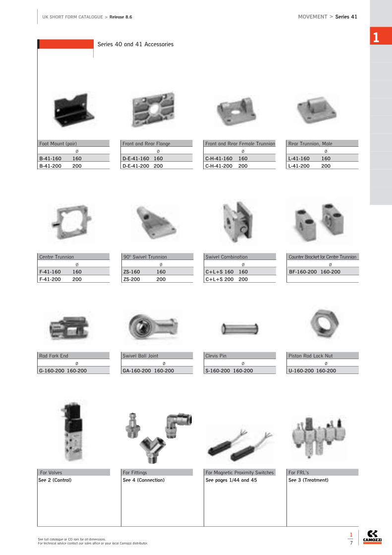
Series 40 and 41 Accessories

Double-acting cushioned, magnetic Ø160, Ø200 DIN/ISO 6431 - VDMA 24562
Series 41 Cylinders - Aluminium Profile
MOVEM
ENT
1
The company reserves the right to vary models and dimensions without notice.Products designed for industrial applications. General terms and conditions for sale are available on www.camozzi.co.uk
MOVEMENT > Series 41 UK SHORT FORM CATALOGUE > Release 8.6
1
6
Technical DataType of ConstructionPiston cylinder with tie-rods.Double-acting and through-rod.Magnetic as standardMediaCompressed air (filtered), with orwithout lubricationOperating PressureMin 1 bar to max 10 barOperating Temperature0oC to +80oC. (with dry air -20oC to +80oC)MaterialsCylinder barrel: Anodised aluminiumextrusionEnd blocks: Cast aluminiumSeals: NBRPiston rod: Stainless steelPiston rod lock nut: Zinc-plated steelTie-rods: Zinc-plated steelTie-rods nuts: Zinc-plated steelCushioningEnd of stroke buffers with adjustablepneumatic cushioningBore Sizes160, 200mm
Stroke LengthsStandard - see tablesNon-standard - on requestSpeedMin 10mm/sec. (no load)Max 500mm/sec. (no load)ConnectionsØ160, Ø200 - 3/4MountingsComprehensive range of ISO/VDMAmounting brackets - see page 1/7Cylinder Piston Force and AirConsumptionRefer to appendix pages 17-20Additional OptionsCylinder sensors - see page 1/44Piston rod accessories - see page 1/7Viton seals**Non-standard available only onrequestSeal Kits available on requestSpecial RequestsFor assistance, contact our technicaloffice or your local Camozzidistributor.
NOTE: Rod nuts and accessories are supplied separately
Double-acting (through rod and non-stanard strokes available on request)
■ Double-acting
Ø160 Ø200
Standard Stroke
50 ■ ■
80 ■ ■
100 ■ ■
150 ■ ■
200 ■ ■
300 ■ ■
400 ■ ■
500 ■ ■
600 ■ ■
700 ■ ■
800 ■ ■
900 ■ ■
1000 ■ ■
For cylinders over 1000mm stroke and other versions, please contact our sales office or your local Camozzi distributor.
CODING EXAMPLE
STANDARD STROKES FOR CYLINDERS SERIES 41
41 M 2 P 160 A 0200 -
41
M
2
P
160
A
0200
SERIES:41
VERSION:M = standard, magnetic
OPERATION:2 = double-acting (front and rear cushions)3 = double-acting (no cushion)4 = double-acting (rear cushions)5 = double-acting (front cushion)6 = double-acting
(through-rod with front and rear cushions)
MATERIALS:P = rolled stainless steel rod
NBR seals, nuts and tie-rods zinc-plated steel
BORE:160, 200mm
TYPE OF DESIGN:A = tie-rodsF = cylinder with centre trunnion
STROKE:(see table)
= standardV = FKM rod sealsW = all FKM seals +130OCC = PU coated cylinder. Colour:Grey*(_ _ _) = extended piston rod _ _ _mm
*Version C: available on request.
1
See full catalogue or CD rom for all dimensions.For technical advice contact our sales office or your local Camozzi distributor.
UK SHORT FORM CATALOGUE > Release 8.6 MOVEMENT > Series 41
1
7
Rear Trunnion, Male
Ø
L-41-160 160
L-41-200 200
Front and Rear Flange
Ø
D-E-41-160 160
D-E-41-200 200
Front and Rear Female Trunnion
Ø
C-H-41-160 160
C-H-41-200 200
Foot Mount (pair)
Ø
B-41-160 160
B-41-200 200
Counter Bracket for Centre Trunnion
Ø
BF-160-200 160-200
90O Swivel Trunnion
Ø
ZS-160 160
ZS-200 200
Swivel Combination
Ø
C+L+S 160 160
C+L+S 200 200
Centre Trunnion
Ø
F-41-160 160
F-41-200 200
Piston Rod Lock Nut
Ø
U-160-200 160-200
Swivel Ball Joint
Ø
GA-160-200 160-200
Clevis Pin
Ø
S-160-200 160-200
Rod Fork End
Ø
G-160-200 160-200
For Fittings
See 4 (Connection)
For Magnetic Proximity Switches
See pages 1/44 and 45
For FRL’s
See 3 (Treatment)
For Valves
See 2 (Control)
Series 40 and 41 Accessories

Single and double-acting, magnetic, cushioned. ISO 15552 - DIN/ISO 6431 - VDMA 24562Standard, low friction and low temperature versionsØ32, Ø40, Ø50, Ø63, Ø80, Ø100, Ø125 .Example of assembly with a valve on page 1/47
Series 60 Cylinders
MOVEM
ENT
1
The company reserves the right to vary models and dimensions without notice.Products designed for industrial applications. General terms and conditions for sale are available on www.camozzi.co.uk
MOVEMENT > Series 60 UK SHORT FORM CATALOGUE > Release 8.6
1
8
Technical DataType of ConstructionPiston cylinder with tie-rods.Single-acting, double-acting andthrough-rod. Magnetic as standardMediaCompressed air (filtered), with orwithout lubricationOperating PressureMin 1 bar to max 10 barOperating TemperatureStandard and low friction: 0oC to+80oC. (with dry air -20oC)Low temperature: (-40oC version): -40oC to 60oC (with dry air -40oC)Low temperature: (-50oC version): -50oC to 60oC (with dry air -50oC)MaterialsCylinder barrel: Anodised aluminiumtubeEnd blocks: Cast aluminiumSeals: NBRPiston rod: Stainless steelPiston rod lock nut: Zinc-plated steelTie-rods: Zinc-plated steelTie-rods nuts: Zinc-plated steelCushioningEnd of stroke buffers with adjustablepneumatic cushioningBore Sizes32, 40, 50, 63, 80, 100, 125mmStroke LengthsStandard - see tablesNon-standard - on requestSpeedMin 10mm/sec. (no load)Max 1000mm/sec. (no load)ConnectionsØ32 - 1/8Ø40, Ø50 - 1/4Ø63, Ø80 - 3/8Ø100, Ø125 - 1/2MountingsComprehensive range of ISO/VDMAmounting brackets - see page 1/9Cylinder GuidesSee page 1/16Cylinder Piston Force and AirConsumptionRefer to appendix pages 17-20Cylinder Breakdown ServiceSame day breakdown service on allstandard and non-standard cylindersAdditional Options Cylinder sensors - see page 1/44Piston rod accessories - see page 1/9Viton seals**Non-standard available only onrequestRod Lock Units - see page 1/48Seal Kits available on requestSpecial RequestsFor assistance, contact our technicaloffice or your local Camozzidistributor.
60M2L = standard version in stock (32 - 125)
Ø32 Ø40 Ø50 Ø63 Ø80 Ø100 Ø125
Standard Stroke
25 ■ ✖ ■ ✖ ■ ✖ ■ ✖ ■ ✖
50 ■ ✖ ■ ✖ ■ ✖ ■ ✖ ■ ✖ ■ ✖ ■ ✖
75 ■ ✖ ■ ✖ ■ ✖ ■ ✖ ■ ✖ ■ ✖ ■ ✖
80 ■ ■ ■ ■ ■ ■ ■
100 ■ ■ ■ ■ ■ ■ ■
125 ■ ■ ■ ■ ■ ■ ■
150 ■ ■ ■ ■ ■ ■ ■
160 ■ ■ ■ ■ ■ ■ ■
200 ■ ■ ■ ■ ■ ■ ■
250 ■ ■ ■ ■ ■ ■ ■
300 ■ ■ ■ ■ ■ ■ ■
320 ■ ■ ■ ■ ■ ■ ■
400 ■ ■ ■ ■ ■ ■ ■
500 ■ ■ ■ ■ ■ ■ ■
600 ■ ■ ■ ■ ■ ■ ■
700 ■ ■ ■ ■ ■ ■ ■
800 ■ ■ ■ ■ ■ ■ ■
900 ■ ■ ■ ■ ■ ■ ■
1000 ■ ■ ■ ■ ■ ■ ■
For cylinders over 1000mm stroke and other versions, please contact our sales office or your local Camozzi distributor.
Double-acting and Single-acting (through rod and non-stanard strokes available on request)
Note: All cylinder are supplied with rod nuts. The accessories are supplied separately
■ Double-acting✖ Single-acting
CODING EXAMPLE
STANDARD STROKES FOR CYLINDERS SERIES 60
60 M 2 L 050 A 0200
60
M
2
L
050
A
0200
SERIES:60 = from Ø32 - 125 DIN/ISO 15552
VERSION:M = magneticN = non magneticL = Low friction, magnetic
MATERIALS:L = rolled stainless steel rod
AISI 420B - anodised aluminiumround tube- NBR seals - nuts and tie-rods
zinc-plated steel- rod seals polyurethane
BORE:32, 40, 50, 63, 80, 100, 125mm
CONSTRUCTION:A = standard with lock nut for rodRL= cylinder with rod lockF = cylinder with centre trunnion
STROKE:(see table)
= standardV = FKM rod sealN = tandemR = NBR rod sealW = all FKM seals +130OCC = PU coated cylinder. Colour: Grey*L = low friction version without rod
seal (rear supply only)**(_ _ _) = extended piston rod _ _ _mmG = with brass rod scraper (chromeplated stainless steel AISI 420B rod,NBR rod seal) [Ø 125 excepted]*Version C: available on request. **The possibility to order the cylinder withoutpiston rod seal, further reduces the frictionforce.
OPERATION:1 = single-acting (front spring)2 = double-acting (front and rear cushions)3 = double-acting (no cushion)4 = double-acting (rear cushions)5 = double-acting (front cushion)6 = double-acting
(through-rod with front and rear cushions)7 = single-acting (through-rod)
SAME
DAY

1
See full catalogue or CD rom for all dimensions.For technical advice contact our sales office or your local Camozzi distributor.
UK SHORT FORM CATALOGUE > Release 8.6 MOVEMENT > Series 60
1
9
Rear Trunnion, Male
Ø
L-41-32 32
L-41-40 40
L-41-50 50
L-41-63 63
L-41-80 80
L-41-100 100
L-41-125 125
Front and Rear Flange
Ø
D-E-41-32 32
D-E-41-40 40
D-E-41-50 50
D-E-41-63 63
D-E-41-80 80
D-E-41-100 100
D-E-41-125 125
Rear Trunnion, Female
Ø
C-41-32 32
C-41-40 40
C-41-50 50
C-41-63 63
C-H-41-80 80
C-H-41-100 100
C-H-41-125 125
Foot Mounts (pair)
Ø
B-41-32 32
B-41-40 40
B-41-50 50
B-41-63 63
B-41-80 80
B-41-100 100
B-41-125 125
Rear Trunnion Ball Joint
Ø
R-41-32 32
R-41-40 40
R-41-50 50
R-41-63 63
R-41-80 80
R-41-100 100
Centre Trunnion
Ø
F-32 32
F-40 40
F-50 50
F-63 63
F-80 80
F-100 100
F-125 125
90O Swivel Trunnion
(to CETOP RP 107P) Ø
ZC 32 32
ZC 40 40
ZC 50 50
ZC 63 63
ZC 80 80
ZC 100 100
ZC 125 125
Front Trunnion, Female
Ø
H-41-32 32
H-41-40 40
H-41-50 50
H-60-63 63
C-H-41-80 80
C-H-41-100 100
C-H-41-125 125
Piston Rod Socket Joint
Ø
GY-32 32
GY-40 40
GY-50-63 50-63
GY-80-100 80-100
Rod Fork End
Ø
G-25-32 32
G-40 40
G-50-63 50-63
G-80-100 80-100
G-41-125 125
Swivel Ball Joint
Ø
GA-32 32
GA-40 40
GA-50-63 50-63
GA-80-100 80-100
GA-41-125 125
Counter Bracket for Centre Trunnion
Ø
BF-32 32
BF-40-50 40-50
BF-63-80 63-80
BF-100-125 100-125
Piston Rod Lock Nut
Ø
U-25-32 32
U-40 40
U-50-63 50-63
U-80-100 80-100
U-41-125 125
Self Aligning Rod
Ø
GK-25-32 32
GK-40 40
GK-50-63 50-63
GK-80-100 80-100
Coupling Piece
Ø
GKF-25-32 32
GKF-40 40
GKF-50-63 50-63
GKF-80-100 80-100
GKF-125 125
Clevis Pin
Ø
S-32 32
S-40 40
S-50 50
S-63 63
S-80 80
S-100 100
S-125 125
Series 60 Accessories

Single and double-acting, magnetic, cushioned. ISO 15552 - DIN/ISO 6431 - VDMA 24562Standard, low friction and low temperature versionsØ 32, Ø40, Ø50, Ø63, Ø80, Ø100, Ø125Example of assembly with a valve on page 1/47
Series 61 Cylinders - Aluminium Profile
MOVEM
ENT
1
The company reserves the right to vary models and dimensions without notice.Products designed for industrial applications. General terms and conditions for sale are available on www.camozzi.co.uk
MOVEMENT > Series 61 UK SHORT FORM CATALOGUE > Release 8.6
1
10
Technical DataType of ConstructionPiston cylinder with tie-rods.Single-acting, double-acting andthrough-rod. Magnetic as standardMediaCompressed air (filtered), with orwithout lubricationOperating PressureMin 1 bar to max 10 barOperating TemperatureStandard and low friction: 0oC to+80oC. (with dry air -20oC)Low temperature: (-40oC version): -40oC to 60oC (with dry air -40oC)Low temperature: (-50oC version): -50oC to 60oC (with dry air -50oC)MaterialsCylinder barrel: Anodised aluminiumextrusionEnd blocks: Cast aluminiumSeals: NBRPiston rod: Stainless steelPiston rod lock nut: Zinc-plated steelTie-rods: Zinc-plated steelTie-rods nuts: Zinc-plated steelCushioningEnd of stroke buffers with adjustablepneumatic cushioningBore Sizes32, 40, 50, 63, 80, 100, 125mmStroke LengthsStandard - see tablesNon-standard - on requestSpeedMin 10mm/sec. (no load)Max 1000mm/sec. (no load)ConnectionsØ32 - 1/8Ø40, Ø50 - 1/4Ø63, Ø80 - 3/8Ø100, Ø125 - 1/2MountingsComprehensive range of ISO/VDMAmounting brackets - see page 1/11Cylinder GuidesSee page 1/16Cylinder Piston Force and AirConsumptionRefer to appendix pages 17-20Cylinder Breakdown ServiceSame day breakdown service on allstandard and non-standard cylindersAdditional OptionsCylinder sensors - see page 1/44Piston rod accessories - see page 1/11Viton seals**Non-standard available only onrequestRod Lock Units - see page 1/48Seal Kits available on requestSpecial RequestsFor assistance, contact our technicaloffice or your local Camozzidistributor.
Ø32 Ø40 Ø50 Ø63 Ø80 Ø100 Ø125
Standard Stroke
25 ■ ✖ ■ ✖ ■ ✖ ■ ✖ ■ ✖
50 ■ ✖ ■ ✖ ■ ✖ ■ ✖ ■ ✖ ■ ✖ ■ ✖
75 ■ ✖ ■ ✖ ■ ✖ ■ ✖ ■ ✖ ■ ✖ ■ ✖
80 ■ ■ ■ ■ ■ ■ ■
100 ■ ■ ■ ■ ■ ■ ■
125 ■ ■ ■ ■ ■ ■ ■
150 ■ ■ ■ ■ ■ ■ ■
160 ■ ■ ■ ■ ■ ■ ■
200 ■ ■ ■ ■ ■ ■ ■
250 ■ ■ ■ ■ ■ ■ ■
300 ■ ■ ■ ■ ■ ■ ■
320 ■ ■ ■ ■ ■ ■ ■
400 ■ ■ ■ ■ ■ ■ ■
500 ■ ■ ■ ■ ■ ■ ■
600 ■ ■ ■ ■ ■ ■ ■
700 ■ ■ ■ ■ ■ ■ ■
800 ■ ■ ■ ■ ■ ■ ■
900 ■ ■ ■ ■ ■ ■ ■
1000 ■ ■ ■ ■ ■ ■ ■
For cylinders over 1000mm stroke and other versions, please contact our sales office or your local Camozzi distributor.
Note: All cylinder are supplied with rod nuts. The accessories are supplied separately61M2P = standard version in stock (32 - 125)
Double-acting and Single-acting (through rod and non-stanard strokes available on request)
■ Double-acting✖ Single-acting
CODING EXAMPLE
STANDARD STROKES FOR CYLINDERS SERIES 61
61 M 2 P 050 A 0200 -
61
M
2
P
050
A
0200
SERIES:61 = from Ø32 - 125
DIN/ISO 15552
VERSION:M = magneticN = non magneticL = Low friction, magnetic
MATERIALS:P = rolled stainless steel rod, AISI
420B anodised profile aluminiumtube NBR seals - rod sealspolyurethane, nuts and tie-rodszinc-plated steel
BORE:32, 40, 50, 63, 80, 100,125mm
CONSTRUCTION:A = standard with rod nutRL= cylinder with rod lock
STROKE:(see table)
= standardV = FKM rod sealN = tandemR = NBR rod sealW = all FKM seals +130OCC = PU coated cylinder. Colour: Grey*L = low friction version without rod
seal (rear supply only)**(_ _ _) = extended piston rod _ _ _mmG = with brass rod scraper (chromeplated stainless steel AISI 420B rod,NBR rod seal) [Ø 125 excepted]*Version C: available on request. **The possibility to order the cylinder withoutpiston rod seal, further reduces the friction force.
OPERATION:1 = single-acting (front spring)2 = double-acting (front and rear cushions)3 = double-acting (no cushion)4 = double-acting (rear cushions)5 = double-acting (front cushion)6 = double-acting
(through-rod with front and rear cushions)7 = single-acting (through-rod)
SAME
DAY

1
See full catalogue or CD rom for all dimensions.For technical advice contact our sales office or your local Camozzi distributor.
UK SHORT FORM CATALOGUE > Release 8.6 MOVEMENT > Series 61
1
11
Rear Trunnion, Male
Ø
L-41-32 32
L-41-40 40
L-41-50 50
L-41-63 63
L-41-80 80
L-41-100 100
L-41-125 125
Front and Rear Flange
Ø
D-E-41-32 32
D-E-41-40 40
D-E-41-50 50
D-E-41-63 63
D-E-41-80 80
D-E-41-100 100
D-E-41-125 125
Rear Trunnion, Female
Ø
C-41-32 32
C-41-40 40
C-41-50 50
C-41-63 63
C-H-41-80 80
C-H-41-100 100
C-H-41-125 125
Foot Mounts (pair)
Ø
B-41-32 32
B-41-40 40
B-41-50 50
B-41-63 63
B-41-80 80
B-41-100 100
B-41-125 125
Trunnion Ball Joint
Ø
R-41-32 32
R-41-40 40
R-41-50 50
R-41-63 63
R-41-80 80
R-41-100 100
R-41-125 125
Centre Trunnion
Ø
F-61-32 32
F-61-40 40
F-61-50 50
F-61-63 63
F-61-80 80
F-61-100 100
F-61-125 125
90O Swivel Trunnion
(to CETOP RP 107P) Ø
ZC-32 32
ZC-40 40
ZC-50 50
ZC-63 63
ZC-80 80
ZC-100 100
ZC-125 125
Front Trunnion, Female
Ø
H-41-32 32
H-41-40 40
H-41-50 50
H-60-63 63
C-H-41-80 80
C-H-41-100 100
C-H-41-125 125
Piston Rod Socket Joint
Ø
GY-32 32
GY-40 40
GY-50-63 50-63
GY-80-100 80-100
Rod Fork End
Ø
G-25-32 32
G-40 40
G-50-63 50-63
G-80-100 80-100
G-41-125 125
Swivel Ball Joint
Ø
GA-32 32
GA-40 40
GA-50-63 50-63
GA-80-100 80-100
GA-41-125 125
Counter Bracket for Centre Trunnion
Ø
BF-32 32
BF-40-50 40-50
BF-63-80 63-80
BF-100-125 100-125
Piston Rod Lock Nut
Ø
U-25-32 32
U-40 40
U-50-63 50-63
U-80-100 80-100
U-41-125 125
Self Aligning Rod
Ø
GK-25-32 25-32
GK-40 40
GK-50-63 50-63
GK-80-100 80-100
Coupling Piece
Ø
GKF-25-32 32
GKF-40 40
GKF-50-63 50-63
GKF-80-100 80-100
GKF-125 125
Clevis Pin
Ø
S-32 32
S-40 40
S-50 50
S-63 63
S-80 80
S-100 100
S-125 125
Series 61 Accessories

MOVEM
ENT
1
The company reserves the right to vary models and dimensions without notice.Products designed for industrial applications. General terms and conditions for sale are available on www.camozzi.co.uk
MOVEMENT > Series 6PF UK SHORT FORM CATALOGUE > Release 8.6
1
12
Double-acting low friction, magnetic ISO 15552Ø50, Ø63, Ø80, Ø100, Ø125
Series 6PF Cylinders - Positioning Feedback
Technical DataPNEUMATIC SECTIONType of ConstructionInner tie-rodsMediaFiltered air class 5.4.4 according toISO 8573-1. If lubricated air is used,it is recommended to use oil ISOVG32. Once applied the lubricationshould never be interruptedOperating PressureMin 0.1 bar to max 10 barOperating Temperature0oC to +80oC. (with dry air -20oC)MaterialsAs codingCushioningNoneBore Sizes50, 63, 80, 100, 125mmStroke Lengths (min - max)50 - 500mm (step 50mm)SpeedMin 5mm/sec. (no load)Max 1000mm/sec. (no load)Max Acceleratation10m/sec2
Max 1000mm/sec. (no load)ConnectionsØ50 - 1/4Ø63, Ø80 - 3/8Ø100, Ø125 - 1/2Mountingsfront and rear flange foot mountsfront / rear / swivel / intermediatetrunnionLinearity0.1% of the strokeRepeatability0.03% of the strokeHysteresis<di 0.5mm
ELECTRICAL SECTIONElectrical ConnectionMale connector M 12 4 poles, IP 67(EN 60529)Max Input Voltage40V (stroke 50mm)60V (strokes from 100 to 500mm)Max Recommended Cursor Current<di 0.1 µAElectrical Resistance5 kohm for strokes from 50 to 300mm10 kohm for strokes from 350 to 500mmTolerance on Resistance+/- 20%Max Dissipation (40°C)1W for stroke 50mm2W for stroke 100mm3W for strokes from 150 to 500mm
Additional OptionsCylinder sensors - see page 1/44Piston rod accessories - see page 1/13
Ø50 Ø63 Ø80 Ø100 Ø125
Standard Stroke
50 ■ ■ ■ ■ ■
100 ■ ■ ■ ■ ■
150 ■ ■ ■ ■ ■
200 ■ ■ ■ ■ ■
250 ■ ■ ■ ■ ■
300 ■ ■ ■ ■ ■
350 ■ ■ ■ ■ ■
400 ■ ■ ■ ■ ■
450 ■ ■ ■ ■ ■
500 ■ ■ ■ ■ ■
■ Double-acting, low friction
CODING EXAMPLE
STANDARD STROKES FOR CYLINDERS SERIES 61
6PF 3 P 050 A 0200
6PF
3
P
050
A
0200
SERIES:6PF = from Ø50 - 125
MATERIALS:P = NBR seals, sintered bronze rodguide bush, chrome plated steel rod,acetal resin piston guide element, nickelplated brass extrusion profile, aluminiumrear endcap, neodymium magneticactuator
BORE:50, 63, 80, 100, 125mm
CONSTRUCTION:A = standard with rod nutRL= cylinder with rod lock
STROKE:(see table)
= standardP = PU rod sealV = FKM rod sealL = without rod seal (rear supply only)*G = with brass rod scraper( _ _ _ ) = extended piston rod _ _ _mm
*The possibility to order the cylinder withoutpiston rod seal further reduces the friction force.
OPERATION:3 = double-acting, low friction (no cushion)
New

1
See full catalogue or CD rom for all dimensions.For technical advice contact our sales office or your local Camozzi distributor.
UK SHORT FORM CATALOGUE > Release 8.6 MOVEMENT > Series 6PF
1
13
Rear Trunnion, Male
Ø
L-41-32 32
L-41-40 40
L-41-50 50
L-41-63 63
L-41-80 80
L-41-100 100
L-41-125 125
Front and Rear Flange
Ø
D-E-41-32 32
D-E-41-40 40
D-E-41-50 50
D-E-41-63 63
D-E-41-80 80
D-E-41-100 100
D-E-41-125 125
Rear Trunnion, Female
Ø
C-41-32 32
C-41-40 40
C-41-50 50
C-41-63 63
C-H-41-80 80
C-H-41-100 100
C-H-41-125 125
Foot Mounts (pair)
Ø
B-41-32 32
B-41-40 40
B-41-50 50
B-41-63 63
B-41-80 80
B-41-100 100
B-41-125 125
Trunnion Ball Joint
Ø
R-41-32 32
R-41-40 40
R-41-50 50
R-41-63 63
R-41-80 80
R-41-100 100
R-41-125 125
Centre Trunnion
Ø
F-61-32 32
F-61-40 40
F-61-50 50
F-61-63 63
F-61-80 80
F-61-100 100
F-61-125 125
90O Swivel Trunnion
(to CETOP RP 107P) Ø
ZC-32 32
ZC-40 40
ZC-50 50
ZC-63 63
ZC-80 80
ZC-100 100
ZC-125 125
Front Trunnion, Female
Ø
H-41-32 32
H-41-40 40
H-41-50 50
H-60-63 63
C-H-41-80 80
C-H-41-100 100
C-H-41-125 125
Piston Rod Socket Joint
Ø
GY-32 32
GY-40 40
GY-50-63 50-63
GY-80-100 80-100
Rod Fork End
Ø
G-25-32 32
G-40 40
G-50-63 50-63
G-80-100 80-100
G-41-125 125
Swivel Ball Joint
Ø
GA-32 32
GA-40 40
GA-50-63 50-63
GA-80-100 80-100
GA-41-125 125
Counter Bracket for Centre Trunnion
Ø
BF-32 32
BF-40-50 40-50
BF-63-80 63-80
BF-100-125 100-125
Piston Rod Lock Nut
Ø
U-25-32 32
U-40 40
U-50-63 50-63
U-80-100 80-100
U-41-125 125
Self Aligning Rod
Ø
GK-25-32 25-32
GK-40 40
GK-50-63 50-63
GK-80-100 80-100
Coupling Piece
Ø
GKF-25-32 32
GKF-40 40
GKF-50-63 50-63
GKF-80-100 80-100
GKF-125 125
Clevis Pin
Ø
S-32 32
S-40 40
S-50 50
S-63 63
S-80 80
S-100 100
S-125 125
Series 6PF Accessories
New

MOVEM
ENT
1
The company reserves the right to vary models and dimensions without notice.Products designed for industrial applications. General terms and conditions for sale are available on www.camozzi.co.uk
MOVEMENT > Series 32 UK SHORT FORM CATALOGUE > Release 8.6
1
14
Series 32M-32F: Single and Double-actingSeries 32R: Double-acting, non-rotatingØ20, Ø25, Ø32, Ø40, Ø50, Ø63, Ø80, Ø100ISO 21287
The Camozzi Series 32 cylinder range has been designed to be installed within confined spaces.These cylinders are suitable for use with feet and with brackets.
Series 32 Compact Magnetic Cylinders
Technical DataType of ConstructionCompact piston cylinder. Single-acting, double-acting, through-rodand non-rotating (double-acting only).Magnetic as standardMediaCompressed air (filtered), with orwithout lubricationOperating Pressure1 bar to 10 bar (double-acting)2 bar to 10 bar (single-acting)Operating Temperature0oC to +80oC. (with dry air -20oC to +80oC)MaterialsCylinder barrel: Anodised aluminiumextrusionEnd blocks: Cast aluminiumSeals: PolyurethanePiston Rod: Stainless steelPiston Rod Lock Nut: Zinc-platedsteelCap Screw: Zinc plated steelCushioningEnd of stoke buffersBore Sizes20, 25, 32, 40, 50, 63, 80, 100mmStroke LengthsStandard - see table.Non-standard- on requestSpeedMin 10mm/sec. (no load)Max 1000mm/sec. (no load)ConnectionsØ20, 25 - M5Ø32, 40, 50, 63, 80 - 1/8Ø100 - 1/4 MountingsComprehensive range of mountingbrackets - see page 1/15Cylinder Piston Force and AirConsumptionRefer to appendix pages 17-20Cylinder Breakdown ServiceSame day breakdown service on allstandard and non-standard cylindersAdditional OptionsMale or female threaded piston rods.Cylinder sensors - see page 1/44Viton seals**Non-standard available only onrequestSeal Kits available on requestSpecial RequestsFor assistance, contact our technicaloffice or your local CamozzidistributorNotesIntermediate brackets for mountingcylinders back to back are availableon request.
Ø20 Ø25 Ø32 Ø40 Ø50 Ø63 Ø80 Ø100
Standard Stroke
5 ■ ✖ ● ■ ✖ ● ■ ✖ ● ■ ✖ ●
10 ■ ✖ ● ■ ✖ ● ■ ✖ ● ■ ✖ ● ■ ✖ ● ■ ✖ ● ■ ✖ ● ■ ✖ ●
15 ■ ✖ ● ■ ✖ ● ■ ✖ ● ■ ✖ ● ■ ✖ ● ■ ✖ ● ■ ✖ ● ■ ✖ ●
20 ■ ✖ ● ■ ✖ ● ■ ✖ ● ■ ✖ ● ■ ✖ ● ■ ✖ ● ■ ✖ ● ■ ✖ ●
25 ■ ✖ ● ■ ✖ ● ■ ✖ ● ■ ✖ ● ■ ✖ ● ■ ✖ ● ■ ✖ ● ■ ✖ ●
30 ■ ● ■ ● ■ ● ■ ● ■ ● ■ ● ■ ● ■ ●
40 ■ ● ■ ● ■ ● ■ ● ■ ● ■ ● ■ ● ■ ●
50 ■ ● ■ ● ■ ● ■ ● ■ ● ■ ● ■ ● ■ ●
60 ■ ● ■ ● ■ ● ■ ● ■ ● ■ ●
75 ■ ● ■ ● ■ ● ■ ● ■ ● ■ ●
80 ■ ● ■ ● ■ ● ■ ● ■ ● ■ ●
100 ■ ● ■ ● ■ ● ■ ● ■ ● ■ ●
Double-acting, Single-acting and Non-rotating (through rod and non-stanard strokes available on request)
■ Double-acting✖ Single-acting● Non-rotating
NOTE: Rod nuts and accessories are supplied separately.
CODING EXAMPLE
STANDARD STROKES FOR CYLINDERS SERIES 32
32 M 2 A 032 A 050 -
32
M
2
A
032
A
050
-
SERIES:32 compact magnetic
VERSION:M = male rod threadF = female rod threadR = non-rotation with flange
OPERATION:1 = single-acting front spring2 = double-acting3 = double-acting through-rod 4 = single-acting rear spring
MATERIALS:A = Anodized aluminium body, end-blocks and piston, PU rod seal,end-covers OR and piston seal
BORE:20, 25, 32, 40, 50, 63, 80, 100mm
CONSTRUCTION:A = standard
STROKE:(see table)
SPECIAL:V = rod seals in vitonW = seals in viton for high
temperatures (140°C) doubleacting non magnetic
SAME
DAY

1
See full catalogue or CD rom for all dimensions.For technical advice contact our sales office or your local Camozzi distributor.
UK SHORT FORM CATALOGUE > Release 8.6 MOVEMENT > Series 32
1
15
Series 32M-32F: Single and double-acting, magnetic Ø25, Ø40, Ø63, Ø100ISO 21287
Series 32 Compact Magnetic Cylinders Tandem and Multi-position Versions
Multi-positionUpto 3 cylinders of different stroke lengths can be joined together
CODING EXAMPLE
SERIES: 32 compact magnetic
VERSION:M = male rod threadF = female rod thread
32 M 2 A 040 A 050 N 2
32M
2
A
040
A
050
N
2OPERATION:2 = double-acting
MATERIALS:A = anodized aluminium body, end-blocks
and piston, PU rod seal, end-coversOR and piston seal
BORE:25, 40, 63, 100mm
STROKEtandem stroke in mmmulti-position X1mm/X2mm
TANDEM AND MULTI-POSITION:
STAGES (only for tandem)2 = 2 stages
CONSTRUCTION: A = standard
Foot Mounts (pair)
Ø
B-32-20 20
B-31-25 25
B-41-32 32
B-41-40 40
B-41-50 50
B-41-63 63
B-41-80 80
B-41-100 100
Rear Trunnion, Female
Ø
C-41-32 32
C-41-40 40
C-41-50 50
C-H-41-63 63
C-H-41-80 80
C-H-41-100 100
Front Trunnion, Female
Ø
H-41-32 32
H-41-40 40
H-41-50 50
H-60-63 63
C-H-41-80 80
C-H-41-100 100
Rear and Front Flange
Ø
D-E-32-20 20
D-E-32-25 25
D-E-41-32 32
D-E-41-40 40
D-E-41-50 50
D-E-41-63 63
D-E-41-80 80
D-E-41-100 100
90O Swivel Trunnion
(to CETOP RP 107P) Ø
ZC 32 32
ZC 40 40
ZC 50 50
ZC 63 63
ZC 80 80
ZC 100 100
90O Swivel Combination for Trunnion
Ø
I-20-25 20
I-20-25 25
Clevis Pin
Ø
S-32 32
S-40 40
S-50 50
S-63 63
S-80 80
S-100 100
Rod Fork End
Ø
G-12-16 12
G-20 16
G-25-32 20-40
G-40 50-63
G-50-63 80
G-80-100 100
Swivel Ball Joint
Ø
GA-12-16 12
GA-20 16
GA-32 20-40
GA-40 50-63
GA-50-63 80
GA-80-100 100
Piston Rod Socket Joint
Ø
GY-12-16 12
GY-20 16
GY-32 20-40
GY-40 50-63
GY-50-63 80
GY-80-100 100
90O Swivel Combination for Female Trunnion
Ø
L-32-20 20
L-32-25 25
L-41-32 32
L-41-40 40
L-41-50 50
L-41-63 63
L-41-80 80
L-41-100 100
Series 32 Accessories
Rear Trunnion Ball Joint
Ø
R-41-32 32
R-41-40 40
R-41-50 50
R-41-63 63
R-41-80 80
R-41-100 100
Piston rod lock nut, centring sleeve and centring pin also available
TandemJoined piston rods to increase thrust

For cylinders DIN/ISO 6432: Ø12, Ø16, Ø20, Ø25For cylinders DIN/ISO 6431: Ø32, Ø40, Ø50, Ø63, Ø80, Ø100
The Camozzi Series 45 are available in three different models depending on the applicable loads.
Series 45 Guide Units
MOVEM
ENT
1
The company reserves the right to vary models and dimensions without notice.Products designed for industrial applications. General terms and conditions for sale are available on www.camozzi.co.uk
MOVEMENT > Series 45 UK SHORT FORM CATALOGUE > Release 8.6
1
16
Technical DataType of ConstructionU and H MediaNUT and NHT without lubrication. NHB requires lubricationOperating Temperature0oC to +80oC. (with dry air -20oC to +80oC)MaterialsBody: anodised aluminium bodyRods: Stainless steel and hardenedsteelCoupling: Flexible stainless steelPlate: anodised aluminiumStroke LengthsMade to measureBreakdown ServiceSame day breakdown service on allstandard and non-standard GuideUnitsSpecial RequestsFor assistance, contact our technicaloffice or your local Camozzidistributor.
Projection X
Diagram N. 3 - “HT” Guide moving on bush (45 NHT)
Diagram N.2 - “HB” guide with linear ball
bearing (45 NHB)
B = centre of gravity for applied loadL = loadX = fixed projection + strokefixed projection = distance to the centre of gravity
Applicable loads on 45 NUT guidesdepending on projection
Applicable loads on 45 NHB andNHT guides depending on projection
CODING EXAMPLE
SERIES: 45
VERSION:N = standard
45 N UT 050 A 0100
45
N
UT
050
A
0100
OPERATION:UT = “U” self lubricating guideHT = “H” self lubricating guideHB = “H” ball guide
BORE:12, 16, 20, 25, 32, 40, 50, 63, 80,100mm
MATERIAL:A = anodised aluminium body
stainless steel columns for UTand HT hardened steel for HB
STROKE:in mm
SAME
DAY

Single-actingØ8, Ø12, Ø20, Ø32, Ø50, Ø63
The Camozzi short-stroke cylinder range has been designed to be installed within confined spaces.
Series QN Short-Stroke Cylinders 1
See full catalogue or CD rom for all dimensions.For technical advice contact our sales office or your local Camozzi distributor.
UK SHORT FORM CATALOGUE > Release 8.6 MOVEMENT > Series QN and QP-QPR
1
17
Ø
8
12
20
32
50
63
QN1A
Stroke
4
4
10
4
10
5
10
25
10
25
10
25
Technical DataType of ConstructionCompact MediaCompressed air (filtered), with orwithout lubricationOperating Pressure2 bar to 10 bar Operating Temperature0oC to +80oC. (with dry air -20oC)MaterialsAluminium Body: NBR sealsOther: Stainless steel and OT58
Bore Sizes8, 12, 20, 32, 50, 63mm
Stroke LengthsSee tableMountingsBy means of holes in bodyCylinder Piston Force and AirConsumptionRefer to appendix pages 17-20CushioningNoneSpecial RequestsFor assistance, contact ourtechnical office or your localCamozzi distributor.
Series QP: Single and double-acting, magneticSeries QPR: Double-acting magnetic, non-rotatingØ12, Ø16, Ø20, Ø25, Ø32, Ø40, Ø50, Ø63, Ø80, Ø100
Series QP-QPR Short-Stroke Cylinders
Ø12 Ø16 Ø20 Ø25 Ø32 Ø40 Ø50 Ø63 Ø80 Ø100
Standard Stroke
5 ■ ✖ ● ■ ✖ ● ■ ✖ ● ■ ✖ ● ■ ✖ ● ■ ✖ ● ■ ✖ ● ■ ✖ ● ■ ✖ ● ■ ✖ ●
10 ■ ✖ ● ■ ✖ ● ■ ✖ ● ■ ✖ ● ■ ✖ ● ■ ✖ ● ■ ✖ ● ■ ✖ ● ■ ✖ ● ■ ✖ ●
15 ■ ✖ ● ■ ✖ ● ■ ✖ ● ■ ✖ ● ■ ✖ ● ■ ✖ ● ■ ✖ ● ■ ✖ ● ■ ✖ ● ■ ✖ ●
20 ■ ✖ ■ ✖ ● ■ ✖ ● ■ ✖ ● ■ ✖ ● ■ ✖ ● ■ ✖ ● ■ ✖ ● ■ ✖ ● ■ ✖ ●
25 ■ ✖ ● ■ ✖ ● ■ ✖ ● ■ ✖ ● ■ ✖ ● ■ ✖ ● ■ ✖ ● ■ ✖ ● ■ ✖ ● ■ ✖ ●
30 ■ ● ■ ● ■ ● ■ ● ■ ● ■ ● ■ ● ■ ● ■ ● ■ ●
35 ■ ■ ● ■ ● ■ ● ■ ● ■ ● ■ ● ■ ● ■ ● ■ ●
40 ■ ■ ● ■ ● ■ ● ■ ● ■ ● ■ ● ■ ● ■ ● ■ ●
45 ■ ■ ● ■ ● ■ ● ■ ● ■ ● ■ ● ■ ● ■ ● ■ ●
50 ■ ● ■ ● ■ ● ■ ● ■ ● ■ ● ■ ● ■ ● ■ ●
60 ■ ● ■ ● ■ ● ■ ● ■ ● ■ ● ■ ● ■ ● ■ ●
75 ■ ● ■ ● ■ ● ■ ● ■ ● ■ ● ■ ● ■ ● ■ ●
80 ■ ● ■ ● ■ ● ■ ● ■ ● ■ ● ■ ● ■ ● ■ ●
100 ■ ● ■ ● ■ ● ■ ● ■ ● ■ ● ■ ● ■ ● ■ ●
■ Double-acting - QP2A✖ Single-acting - QP1A● Non-rotating - QPR2A
STANDARD STROKE FOR COMPACT MAGNETIC CYLINDERS
Technical DataType of ConstructionCompact profile (QP), compact withnon rotating guides (QPR)MediaCompressed air (filtered), with orwithout lubricationOperating Pressure1 bar to 10 bar (double-acting)2 bar to 10 bar (single-acting)Operating Temperature0oC to +80oC. (with dry air -20oC)MaterialsAluminium Body Anodised, NBR seals, rolled stainless steel rod
Bore Sizes12, 16, 20, 25, 32, 40, 50, 63, 80,100Stroke LengthsSee tableMountingsBy means of holes in bodyCylinder Piston Force and AirConsumptionRefer to appendix pages 17-20CushioningNoneSpecial RequestsFor assistance, contact our technicaloffice or your local Camozzi distributor.
NOTE: Foot (model B) and Male Trunnion (model L) brackets available on request. Ø32, 40, 50, 63, 80, 100mm
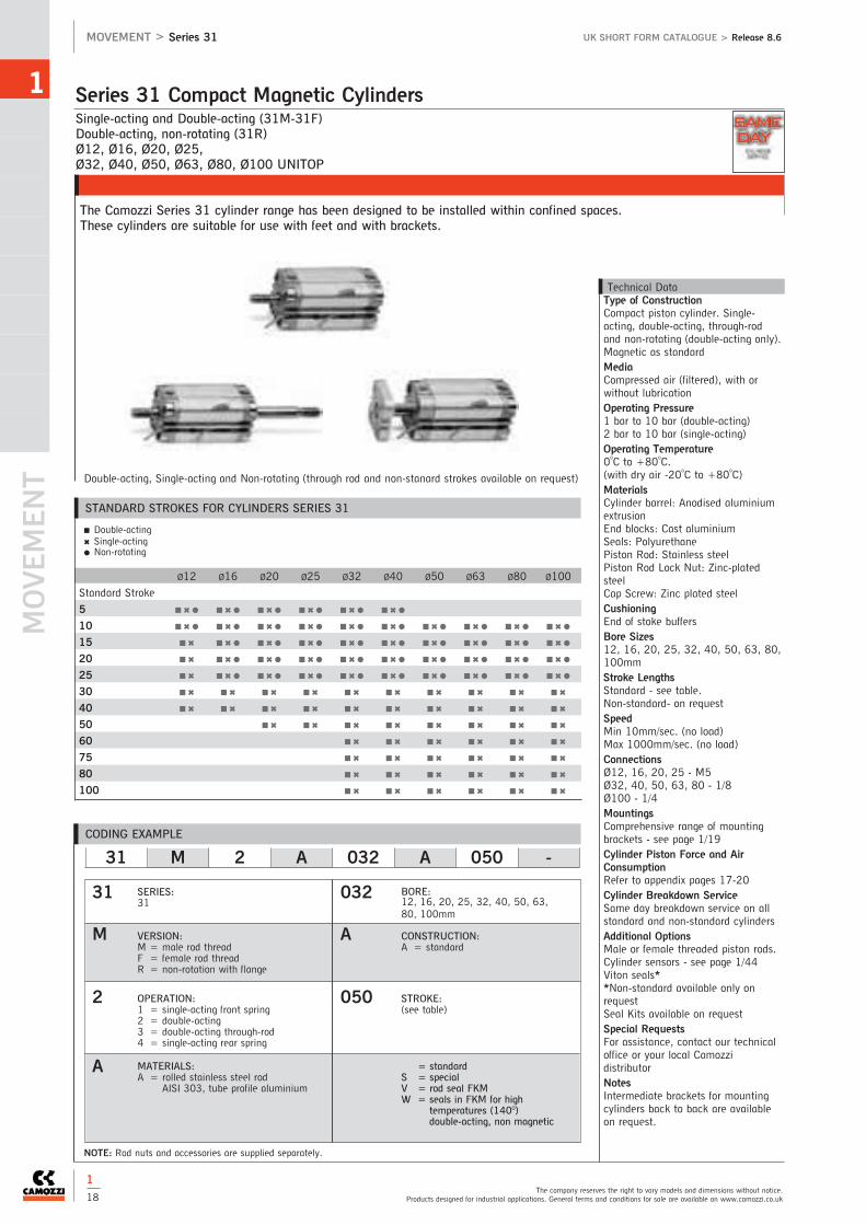
Single-acting and Double-acting (31M-31F)Double-acting, non-rotating (31R)Ø12, Ø16, Ø20, Ø25, Ø32, Ø40, Ø50, Ø63, Ø80, Ø100 UNITOP
The Camozzi Series 31 cylinder range has been designed to be installed within confined spaces.These cylinders are suitable for use with feet and with brackets.
Series 31 Compact Magnetic Cylinders
MOVEM
ENT
1
The company reserves the right to vary models and dimensions without notice.Products designed for industrial applications. General terms and conditions for sale are available on www.camozzi.co.uk
MOVEMENT > Series 31 UK SHORT FORM CATALOGUE > Release 8.6
1
18
Technical DataType of ConstructionCompact piston cylinder. Single-acting, double-acting, through-rodand non-rotating (double-acting only).Magnetic as standardMediaCompressed air (filtered), with orwithout lubricationOperating Pressure1 bar to 10 bar (double-acting)2 bar to 10 bar (single-acting)Operating Temperature0oC to +80oC. (with dry air -20oC to +80oC)MaterialsCylinder barrel: Anodised aluminiumextrusionEnd blocks: Cast aluminiumSeals: PolyurethanePiston Rod: Stainless steelPiston Rod Lock Nut: Zinc-platedsteelCap Screw: Zinc plated steelCushioningEnd of stoke buffersBore Sizes12, 16, 20, 25, 32, 40, 50, 63, 80,100mmStroke LengthsStandard - see table.Non-standard- on requestSpeedMin 10mm/sec. (no load)Max 1000mm/sec. (no load)ConnectionsØ12, 16, 20, 25 - M5Ø32, 40, 50, 63, 80 - 1/8Ø100 - 1/4MountingsComprehensive range of mountingbrackets - see page 1/19Cylinder Piston Force and AirConsumptionRefer to appendix pages 17-20Cylinder Breakdown ServiceSame day breakdown service on allstandard and non-standard cylindersAdditional OptionsMale or female threaded piston rods.Cylinder sensors - see page 1/44Viton seals**Non-standard available only onrequestSeal Kits available on requestSpecial RequestsFor assistance, contact our technicaloffice or your local CamozzidistributorNotesIntermediate brackets for mountingcylinders back to back are availableon request.
Ø12 Ø16 Ø20 Ø25 Ø32 Ø40 Ø50 Ø63 Ø80 Ø100
Standard Stroke
5 ■ ✖ ● ■ ✖ ● ■ ✖ ● ■ ✖ ● ■ ✖ ● ■ ✖ ●
10 ■ ✖ ● ■ ✖ ● ■ ✖ ● ■ ✖ ● ■ ✖ ● ■ ✖ ● ■ ✖ ● ■ ✖ ● ■ ✖ ● ■ ✖ ●
15 ■ ✖ ■ ✖ ● ■ ✖ ● ■ ✖ ● ■ ✖ ● ■ ✖ ● ■ ✖ ● ■ ✖ ● ■ ✖ ● ■ ✖ ●
20 ■ ✖ ■ ✖ ● ■ ✖ ● ■ ✖ ● ■ ✖ ● ■ ✖ ● ■ ✖ ● ■ ✖ ● ■ ✖ ● ■ ✖ ●
25 ■ ✖ ■ ✖ ● ■ ✖ ● ■ ✖ ● ■ ✖ ● ■ ✖ ● ■ ✖ ● ■ ✖ ● ■ ✖ ● ■ ✖ ●
30 ■ ✖ ■ ✖ ■ ✖ ■ ✖ ■ ✖ ■ ✖ ■ ✖ ■ ✖ ■ ✖ ■ ✖
40 ■ ✖ ■ ✖ ■ ✖ ■ ✖ ■ ✖ ■ ✖ ■ ✖ ■ ✖ ■ ✖ ■ ✖
50 ■ ✖ ■ ✖ ■ ✖ ■ ✖ ■ ✖ ■ ✖ ■ ✖ ■ ✖
60 ■ ✖ ■ ✖ ■ ✖ ■ ✖ ■ ✖ ■ ✖
75 ■ ✖ ■ ✖ ■ ✖ ■ ✖ ■ ✖ ■ ✖
80 ■ ✖ ■ ✖ ■ ✖ ■ ✖ ■ ✖ ■ ✖
100 ■ ✖ ■ ✖ ■ ✖ ■ ✖ ■ ✖ ■ ✖
Double-acting, Single-acting and Non-rotating (through rod and non-stanard strokes available on request)
■ Double-acting✖ Single-acting● Non-rotating
NOTE: Rod nuts and accessories are supplied separately.
CODING EXAMPLE
STANDARD STROKES FOR CYLINDERS SERIES 31
31 M 2 A 032 A 050 -
31
M
2
A
032
A
050
SERIES:31
VERSION:M = male rod threadF = female rod threadR = non-rotation with flange
OPERATION:1 = single-acting front spring2 = double-acting3 = double-acting through-rod 4 = single-acting rear spring
MATERIALS:A = rolled stainless steel rod
AISI 303, tube profile aluminium
BORE:12, 16, 20, 25, 32, 40, 50, 63,80, 100mm
CONSTRUCTION:A = standard
STROKE:(see table)
= standardS = specialV = rod seal FKMW = seals in FKM for high
temperatures (140O) double-acting, non magnetic
SAME
DAY

Double-acting (31M-31F)Ø12, Ø16, Ø20, Ø25, Ø32, Ø40, Ø50, Ø63, Ø80, Ø100
Series 31 Compact Magnetic Cylinders Tandem and Multi-position Versions 1
See full catalogue or CD rom for all dimensions.For technical advice contact our sales office or your local Camozzi distributor.
UK SHORT FORM CATALOGUE > Release 8.6 MOVEMENT > Series 31
1
19
TandemJoined piston rods to increase thrust
Foot Mounts (pair)
Ø
B-31-12-16 12-16
B-31-20 20
B-31-25 25
B-31-32 32
B-31-40 40
B-31-50 50
B-31-63 63
B-31-80 80
B-31-100 100
Rear and Front Flange
Ø
D-E-31-12-16 12-16
D-E-31-20 20
D-E-31-25 25
D-E-31-32 32
D-E-31-40 40
D-E-31-50 50
D-E-31-63 63
D-E-31-80 80
D-E-31-100 100
Rear Trunnion, Female
Ø
C-31-32 32
C-31-40 40
C-31-50 50
C-31-63 63
C-31-80 80
C-31-100 100
Rear Trunnion, Male
Ø
L-31-12-16 12
L-31-12-16 16
L-31-20 20
L-31-25 25
90O Swivel Combination for Trunnion
Ø
I-12-16 12
I-12-16 16
I-20-25 20
I-20-25 25
Rod Fork End
Ø
G-12-16 12
G-20 16
G-25-32 20-40
G-40 50-63
G-50-63 80
G-80-100 100
Swivel Ball Joint
Ø
GA-12-16 12
GA-20 16
GA-32 20-40
GA-40 50-63
GA-50-63 80
GA-80-100 100
Piston Rod Socket Joint
Ø
GY-12-16 12
GY-20 16
GY-32 20-40
GY-40 50-63
GY-50-63 80
GY-80-100 100
Piston Rod Lock Nut
Ø
U-12-16 12
U-20 16
U-25-32 20-40
U-40 50-63
U-50-63 80
U-80-100 100
Self Aligning Rod
Ø
GK-20 16
GK-25-32 20-25-32-40
GK-40 50-63
GK-50-63 80
GK-80-100 100
Coupling Piece
Ø
GKF-20 16
GKF-25-32 20-25-32-40
GKF-40 50-63
GKF-50-63 80
GKF-80-100 100
90O Swivel Combination for Female Trunnion
Ø
ZC-32 32
ZC-40 40
ZC-50 50
ZC-63 63
ZC-80 80
ZC-100 100
Multi-positionUpto 3 cylinders of different stroke lengths can be joined together
Series 31 Accessories
CODING EXAMPLE
SERIES: 31
VERSION:M = male rod threadF = female rod threadR = non-rotating with flange only double-acting
31 M 2 A 032 A 050 N 2
31
M
2
A
032
A
050
N
2OPERATION:2 = double-acting
MATERIALS:A = rolled stainless steel
rod AISI 303 - AL tubeprofile
BORE:12, 16, 20, 25, 32, 40, 50, 63,80, 100mm
STROKE:- tandem stroke in mm- multi-position X1mm/X2mm** insert strokes without the initial 0
TANDEM AND MULTI-POSITION:
STAGES: (only for tandem)2 = 2 stages 4 = 4 stages3 = 3 stages
CONSTRUCTION: A = standard

Double-acting, magnetic piston, guidedØ20, Ø25, Ø32, Ø40, Ø50, Ø63
The Camozzi QC compact cylinders are designed to be used in applications where space is limited and when the load mustbe guided to prevent rotation.
Series QCT and QCB Cylinders with Integrated Guide
MOVEM
ENT
1
The company reserves the right to vary models and dimensions without notice.Products designed for industrial applications. General terms and conditions for sale are available on www.camozzi.co.uk
MOVEMENT > Series QCT and QCB UK SHORT FORM CATALOGUE > Release 8.6
Technical DataType of ConstructionCompact guidedQCT - Sintered bronze bushesQCB - Linear ball bearings MediaClean air, non lubricated. If lubricatedoil is used, it is recommended to useoil ISOVG32. Once applied thelubrication should never beinterruptedOperating PressureMin 1 bar to max 10 barOperating Temperature0oC to +80oC. (with dry air -20oC to +80oC)MaterialsBody: anodised aluminiumFront Mounting Plate: Zinc plated steelPiston Rod: Stainless steel AISI 303QCT Columns: Stainless Steel 420BQCB Columns: Hardened Steel C50Bore Sizes20, 25, 32, 40, 50, 63mm
Stroke LengthsStandard, see tableSpeedMin 50mm/sec. (no load)Max 500mm/sec. (no load)Connections1/8MountingsThreaded and non-threaded holes inthe bodyCylinder Piston Force and AirConsumptionRefer to appendix pages 17-20Additional OptionsCylinder sensors - see page 1/44Special RequestsFor assistance, contact our technicaloffice or your local Camozzidistributor
Ø20 Ø25 Ø32 Ø40 Ø50 Ø63
Standard Stroke
20 ■ ■
25 ■ ■ ■ ■
30 ■ ■
40 ■ ■
50 ■ ■ ■ ■ ■ ■
75 ■ ■ ■ ■ ■ ■
100 ■ ■ ■ ■ ■ ■
125 ■ ■ ■ ■ ■ ■
150 ■ ■ ■ ■ ■ ■
175 ■ ■ ■ ■ ■ ■
200 ■ ■ ■ ■ ■ ■
Note: Non standard models available only on request.
For these strokes (e.g. stroke 35) please consider the size of the nearest standard stroke.
Double-acting QCT Type
■ Double-acting
1
20
CODING EXAMPLE
QC T 2 A 020 A 050 -
QC
T
2
A
020
A
050
-
SERIES:QC
VERSION:T = sintered bronze bushesB = linear ball bearings
OPERATION:2 = double-acting
MATERIALS:A = anodised aluminium body,
stainless steel piston rod, stainlesssteel QCT columns, hardenedsteel QCB columns
BORE:20, 25, 32, 40, 50, 63mm
TYPE OF DESIGN:A = standard
STROKE:(see table)** Non standard models available only
on request. For these strokes (e.g. stroke 35) please consider the size of thenearest standard strokes.
SPECIAL:to be specified
STANDARD STROKES FOR CYLINDERS SERIES QC

Double-acting, magnetic piston, with double bearing and flangesØ20, Ø25, Ø32, Ø40
Series QCTF - QCBF Slide Units 1
See full catalogue or CD rom for all dimensions.For technical advice contact our sales office or your local Camozzi distributor.
UK SHORT FORM CATALOGUE > Release 8.6 MOVEMENT > Series QCTF - QCBF
Technical DataType of ConstructionCompact guided with extended guiderods and double bearings/flangesQCTF - Sintered bronze bushesQCBF - Linear ball bearings MediaClean air, non lubricated. If lubricatedoil is used, it is recommended to useoil ISOVG32. Once applied thelubrication should never beinterruptedOperating PressureMin 1 bar to max 10 barOperating Temperature0oC to +80oC. (with dry air -20oC to +80oC)MaterialsBody: anodised aluminiumFlanges: Zinc plated steelPiston Rod: Stainless steel AISI 303QCTF Columns: Stainless Steel 420BQCBF Columns: Hardened Steel C50CushioningSee cylinder coding series QCTF andQCBFBore Sizes20, 25, 32, 40mmStroke LengthsStandard, see tableSpeedMin 50mm/secMax 500mm/secConnections1/8MountingsThreaded and non threaded holes inthe bodyCylinder Piston Force and AirConsumptionRefer to appendix pages 17-20Additional OptionsCylinder sensors - see page 1/44Special RequestsFor assistance, contact our technicaloffice or your local Camozzidistributor.
Ø20 Ø25 Ø32 Ø40
Standard Stroke
20 ■ ■
25 ■ ■
30 ■ ■
40 ■ ■
50 ■ ■ ■ ■
75 ■ ✖ ■ ✖ ■ ■
100 ■ ✖ ■ ✖ ■ ✖ ■ ✖
125 ■ ✖ ■ ✖ ■ ✖ ■ ✖
150 ■ ✖ ■ ✖ ■ ✖ ■ ✖
175 ■ ✖ ■ ✖ ■ ✖ ■ ✖
200 ■ ✖ ■ ✖ ■ ✖ ■ ✖
Note: Non standard models available only on request.
For these strokes (e.g. stroke 35) please consider the size of the nearest standard stroke.
■ Cushioning type A and C✖ Cushioning type B
1
21
STANDARD STROKE FOR SERIES QCTF AND QCBF
CODING EXAMPLE
QC T F 2 A 020 A 050
QC
T
F
2
A
020
A
050
SERIES:QC
TYPE OF BEARINGT = sintered bronze bushesB = linear ball bearings
INSTALLATION TYPEF = body mounted with moving flanges
OPERATION2 = double acting
MATERIALSA = anodised aluminium body,
stainless steel piston rod,stainless steel columns (QCT),hardened steel columns (QCB)
BORE20, 25, 32, 40mm
CUSHIONA = fixed mechanical cushion(standard)B = two shock absorbers located on
the bodyC = one shock absorber located on
the rear flange
STROKE (see table)

Double-acting, magnetic, guided Ø10x2, 16x2, 20x2, 25x2, 32x2
Series QX Twin Rod Cylinders
MOVEM
ENT
1
The company reserves the right to vary models and dimensions without notice.Products designed for industrial applications. General terms and conditions for sale are available on www.camozzi.co.uk
MOVEMENT > Series QX UK SHORT FORM CATALOGUE > Release 8.6
1
22
Technical DataType of ConstructionCompact non magnetic, double actingQXT - Sintered bronze bushesQXB - Linear ball bearings MediaClean air, non lubricated. If lubricatedoil is used, it is recommended to useoil ISOVG32. Once applied thelubrication should never beinterruptedOperating PressureMin 2.5 bar to max 8 barOperating Temperature0oC to +80oC. (with dry air -20oC to +80oC)MaterialsBody and Flanges: Anodised aluminiumPiston Rod: QXT: Stainless steel AISI 303QXB: Hardened steel C50Bore Sizes10, 16, 20, 25, 32mmStroke LengthsStandard, see tableConnectionsØ10, 16, 20, 25 - M5Ø32 - 1/8MountingsThreaded holes in the bodyCylinder Piston Force and AirConsumptionRefer to appendix pages 17-20Additional OptionsCylinder sensors - see page 1/44Special RequestsFor assistance, contact our technicaloffice or your local Camozzidistributor.
Ø10 Ø16 Ø20 Ø25 Ø32
Standard Stroke
10 ■ ■ ■ ■ ■
20 ■ ■ ■ ■ ■
30 ■ ■ ■ ■ ■
40 ■ ■ ■ ■ ■
50 ■ ■ ■ ■ ■
75 ■ ■ ■ ■ ■
100 ■ ■ ■ ■
■ Double - acting
STANDARD STROKES FOR CYLINDERS SERIES QX
CODING EXAMPLE
QX T 2 A 020 A 050
QX
T
2
A
020
A
050
SERIES:QX
VERSIONT = sintered bronze bushesB = linear ball bearings
OPERATION2 = double acting (1 flange) radial
pressure supply3 = through-rod (double-flange), radial
pressure supply
MATERIALSA = anodised aluminium body, rolled
stainless steel piston 303 pistonrod
BORE10, 16, 20, 25, 32mm
TYPE OF DESIGNA = standard
STROKE (see table)

Single-actingØ6, Ø10, Ø16: Stroke 5, 10, 15mmwith Super-Rapid fitting 4mm and M5 connection.
The Camozzi Series 14 cylinder range has been designed to be installed in very small spaces. The cylinders are designed to be bulkhead mounted either individually or in banks.
Series 14 Compact Mini-Cylinders 1
See full catalogue or CD rom for all dimensions.For technical advice contact our sales office or your local Camozzi distributor.
UK SHORT FORM CATALOGUE > Release 8.6 MOVEMENT > Series 14
1
23
Non Threaded Piston Rod - Threaded Connection
Ø Stroke
14N1M06A05 6 5
14N1M06A10 6 10
14N1M06A15 6 15
14N1M10A05 10 5
14N1M10A10 10 10
14N1M10A15 10 15
14N1M16A05 16 5
14N1M16A10 16 10
14N1M16A15 16 15
Non Threaded Piston Rod - Super-Rapid Connection
Ø Stroke
14N1A06A05 6 5
14N1A06A10 6 10
14N1A06A15 6 15
14N1A10A05 10 5
14N1A10A10 10 10
14N1A10A15 10 15
14N1A16A05 16 5
14N1A16A10 16 10
14N1A16A15 16 15
Threaded Piston Rod - Threaded Connection
Ø Stroke
14N1M06B05 6 5
14N1M06B10 6 10
14N1M06B15 6 15
14N1M10B05 10 05
14N1M10B10 10 10
14N1M10B15 10 15
14N1M16B05 16 05
14N1M16B10 16 10
14N1M16B15 16 15
Threaded Piston Rod - Super-Rapid Connection
Ø Stroke
14N1A06B05 6 5
14N1A06B10 6 10
14N1A06B15 6 15
14N1A10B05 10 5
14N1A10B10 10 10
14N1A10B15 10 15
14N1A16B05 16 5
14N1A16B10 16 10
14N1A16B15 16 15
Technical DataType of ConstructionCompact piston cylinderSingle-acting onlyNon-magnetic MediaCompressed air (filtered), with orwithout lubricationOperating PressureMin 1 bar to max 8 barOperating Temperature0oC to +80oC. (with dry air -20oC to +80oC)MaterialsBody: Nickel-plated brassSeals: NBRPiston Rod: Stainless steelBore Sizes6, 10, 16mmStroke LengthsSee tableConnections4mm push-in tube or M5 threadconnectionMountingsBy threaded bodyCylinder Piston Force and AirConsumptionRefer to appendix pages 17-20Special RequestsFor assistance, contact our technicaloffice or your local Camozzidistributor.
Single-acting Single-acting
Single-acting Single-acting

Series 27 Roundline Cylinders
MOVEM
ENT
1
The company reserves the right to vary models and dimensions without notice.Products designed for industrial applications. General terms and conditions for sale are available on www.camozzi.co.uk
MOVEMENT > Series 27 UK SHORT FORM CATALOGUE > Release 8.6
Technical DataType of ConstructionPiston cylinder - rolled constructionDouble-acting. Magnetic as standardMediaCompressed air (filtered), with orwithout lubricationOperating PressureMin 1 bar to Max 10 barOperating Temperature0oC to +80oC. (with dry air -20oC to +80oC)MaterialsCylinder barrel: Stainless steelEnd Blocks: Cast aluminiumSeals: NBR / PolyurethanePiston Rod: Stainless steelPiston Lock Nut: Zinc-plated steelNose Nut: Zinc-plated steelCushioningEnd of stroke buffersBore Sizes20, 25, 32, 40, 50, 63mmStroke LengthsStandard - see table.Non-standard - on requestSpeedMin 10mm/sec. (no load)Max 1000mm/sec. (no load)ConnectionsØ20, 25, 32, 40 - 1/8Ø50, 63 - 1/4NB: Connections are not spot-facedMountingsCylinder feet or rear trunnionbrackets - see page 1/25 for all sizes.Bulkhead mounting Ø20 to Ø40inclusive - threaded holes in endblocks Ø50 and Ø63 onlyTrunnion pins Ø50 and Ø63 only.Cylinder GuidesSee page 1/16Cylinder Piston Force and AirConsumptionRefer to appendix pages 17-20Cylinder Breakdown ServiceSame day breakdown service on allstandard and non-standard cylindersAdditional OptionsCylinder sensors - see page 1/44Piston rod accessories - see page 1/25Viton seals**Non-standard available only onrequestSpecial RequestsFor assistance, contact our technicaloffice or your local Camozzidistributor.
Double-acting only (non-standard strokes available on request)
Mod. M Mod. T Mod. U
Bore Sizes: 20, 25, 32, 40 Bore Sizes: 20, 25, 32, 40 Bore Sizes: 20, 25, 32, 40, 50, 63
■ Double-acting
Ø20 Ø25 Ø32 Ø40 Ø50 Ø63
Standard Stroke
10 ■ ■ ■ ■ ■ ■
25 ■ ■ ■ ■ ■ ■
40 ■ ■ ■ ■ ■ ■
50 ■ ■ ■ ■ ■ ■
80 ■ ■ ■ ■ ■ ■
100 ■ ■ ■ ■ ■ ■
125 ■ ■ ■ ■ ■ ■
160 ■ ■ ■ ■ ■ ■
200 ■ ■ ■ ■ ■ ■
250 ■ ■ ■ ■ ■ ■
300 ■ ■ ■ ■ ■ ■
320 ■ ■ ■ ■ ■ ■
400 ■ ■ ■ ■ ■ ■
500 ■ ■ ■ ■ ■ ■
STANDARD STROKES FOR CYLINDERS SERIES 27
Double-acting, MagneticØ20, Ø25, Ø32, Ø40, Ø50, Ø63
The Camozzi Series 27 cylinder range has been designed incorporating reduced dimensions and clean lines, suitable for awide range of industrial applications.
1
24
CODING EXAMPLE
27 M 2 A 20 A 0050 -
27
M
2
A
20
A
0050
-
SERIES:27
VERSION:M = Standard rear end housing,
trunnion hole, side portT = End ported rear housingU = Side ported rear housing
OPERATION:2 = double-acting
MATERIALS:A = rolled stainless steel
rod-stainless steel tube
BORE:20, 25, 32, 40, 50, 63mm
TYPE OF DESIGN:A = standard
STROKE:(see table)
SPECIAL:to be specified
SAME
DAY

1
See full catalogue or CD rom for all dimensions.For technical advice contact our sales office or your local Camozzi distributor.
UK SHORT FORM CATALOGUE > Release 8.6 MOVEMENT > Series 27
Rear Trunnion Bracket (pair)
Ø
I-27-50 50
I-27-63 63
Foot Mounts (single)
Ø
B-27-20 20
B-27-25 25
B-27-32 32
B-27-40 40
Foot Mounts (pair)
Ø
B-27-50 50
B-27-63 63
Rear Trunnion Bracket
Ø
I-27-20 20
I-27-25 25
I-27-32 32
I-27-40 40
Piston Rod Socket Joint
Ø
GY-20 20
GY-32 25-32
GY-40 40-50
GY-50-63 63
Threaded Trunnion Pin
Ø
T-42-50 50
T-42-63 63
Rod Fork End
Ø
G-20 20
G-25-32 25-32
G-40 40-50
G-50-63 63
Swivel Ball Joint
Ø
GA-20 20
GA-32 25-32
GA-40 40-50
GA-50-63 63
Piston Rod Lock Nut
Ø
U-20 20
U-25-32 25-32
U-40 40-50
U-50-63 63
Nose Nut
Ø
V-12-16 20
V-27-25 25
V-20-25 32
V-42-32 40
Self Aligning Rod
Ø
GK-20 16
GK-25-32 25-32
GK-40 40-50
GK-50-63 63
Coupling Piece
Ø
GKF-20 20
GKF-25-32 25-32
GKF-40 40-50
GKF-50-63 63
Series 27 Accessories
1
25
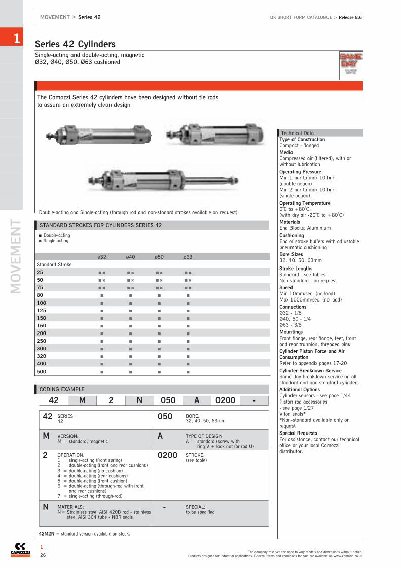
Single-acting and double-acting, magneticØ32, Ø40, Ø50, Ø63 cushioned
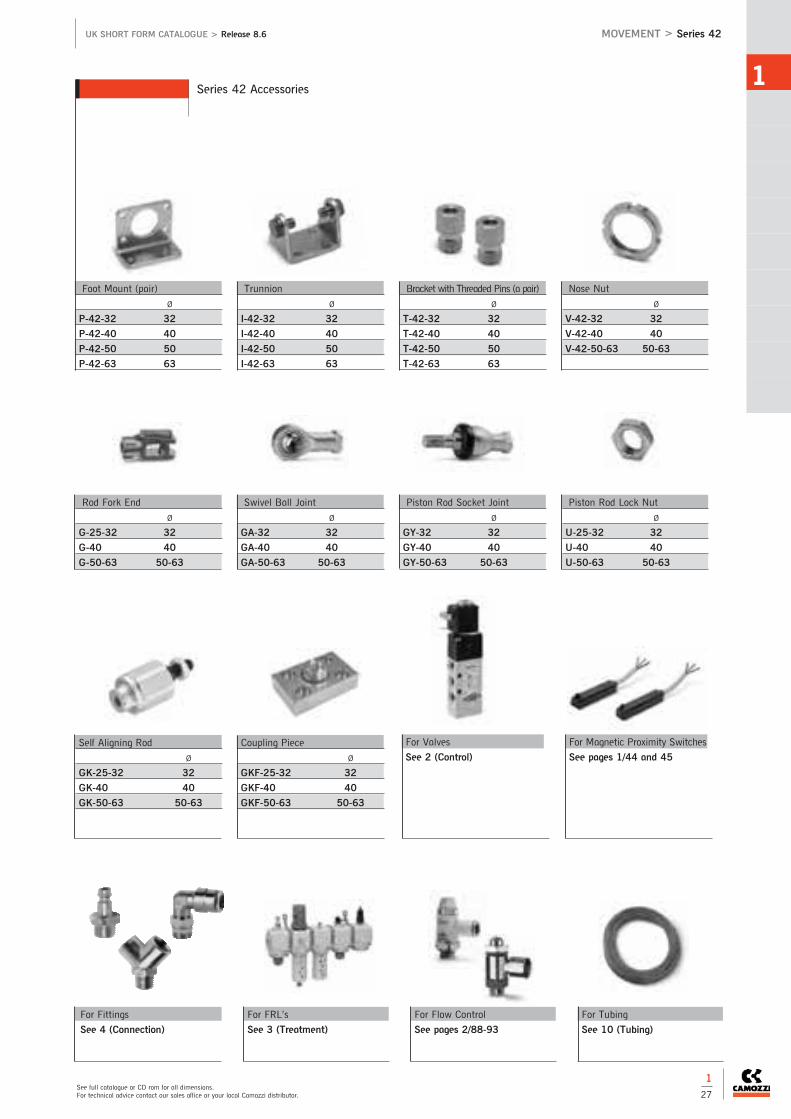
The Camozzi Series 42 cylinders have been designed without tie rodsto assure an extremely clean design
Series 42 Cylinders
MOVEM
ENT
1
The company reserves the right to vary models and dimensions without notice.Products designed for industrial applications. General terms and conditions for sale are available on www.camozzi.co.uk
MOVEMENT > Series 42 UK SHORT FORM CATALOGUE > Release 8.6
Technical DataType of ConstructionCompact - flanged MediaCompressed air (filtered), with orwithout lubricationOperating PressureMin 1 bar to max 10 bar (double action) Min 2 bar to max 10 bar (single action)Operating Temperature0oC to +80oC. (with dry air -20oC to +80oC)MaterialsEnd Blocks: AluminiumCushioningEnd of stroke buffers with adjustablepneumatic cushioningBore Sizes32, 40, 50, 63mm
Stroke LengthsStandard - see tablesNon-standard - on requestSpeedMin 10mm/sec. (no load)Max 1000mm/sec. (no load)ConnectionsØ32 - 1/8Ø40, 50 - 1/4Ø63 - 3/8MountingsFront flange, rear flange, feet, frontand rear trunnion, threaded pinsCylinder Piston Force and AirConsumptionRefer to appendix pages 17-20Cylinder Breakdown ServiceSame day breakdown service on allstandard and non-standard cylindersAdditional OptionsCylinder sensors - see page 1/44Piston rod accessories - see page 1/27Viton seals**Non-standard available only onrequestSpecial RequestsFor assistance, contact our technicaloffice or your local Camozzidistributor.
Double-acting and Single-acting (through rod and non-stanard strokes available on request)
■ Double-acting✖ Single-acting
1
26
42M2N = standard version available on stock.
Ø32 Ø40 Ø50 Ø63
Standard Stroke
25 ■ ✖ ■ ✖ ■ ✖ ■ ✖
50 ■ ✖ ■ ✖ ■ ✖ ■ ✖
75 ■ ✖ ■ ✖ ■ ✖ ■ ✖
80 ■ ■ ■ ■
100 ■ ■ ■ ■
125 ■ ■ ■ ■
150 ■ ■ ■ ■
160 ■ ■ ■ ■
200 ■ ■ ■ ■
250 ■ ■ ■ ■
300 ■ ■ ■ ■
320 ■ ■ ■ ■
400 ■ ■ ■ ■
500 ■ ■ ■ ■
STANDARD STROKES FOR CYLINDERS SERIES 42
CODING EXAMPLE
42 M 2 N 050 A 0200 -
050
A
0200
-
SERIES:42
VERSION:M = standard, magnetic
BORE:32, 40, 50, 63mm
TYPE OF DESIGN A = standard (screw with
ring V + lock nut for rod U)
STROKE:(see table)
SPECIAL:to be specified
MATERIALS:N= Strainless steel AISI 420B rod - stainless
steel AISI 304 tube - NBR seals
OPERATION:1 = single-acting (front spring)2 = double-acting (front and rear cushions)3 = double-acting (no cushion)4 = double-acting (rear cushions)5 = double-acting (front cushion)6 = double-acting (through-rod with front
and rear cushions)7 = single-acting (through-rod)
42
M
2
N
SAME
DAY
1
See full catalogue or CD rom for all dimensions.For technical advice contact our sales office or your local Camozzi distributor.
UK SHORT FORM CATALOGUE > Release 8.6 MOVEMENT > Series 42
1
27
Nose Nut
Ø
V-42-32 32
V-42-40 40
V-42-50-63 50-63
Trunnion
Ø
I-42-32 32
I-42-40 40
I-42-50 50
I-42-63 63
Bracket with Threaded Pins (a pair)
Ø
T-42-32 32
T-42-40 40
T-42-50 50
T-42-63 63
Foot Mount (pair)
Ø
P-42-32 32
P-42-40 40
P-42-50 50
P-42-63 63
Piston Rod Lock Nut
Ø
U-25-32 32
U-40 40
U-50-63 50-63
Swivel Ball Joint
Ø
GA-32 32
GA-40 40
GA-50-63 50-63
Piston Rod Socket Joint
Ø
GY-32 32
GY-40 40
GY-50-63 50-63
Rod Fork End
Ø
G-25-32 32
G-40 40
G-50-63 50-63
Coupling Piece
Ø
GKF-25-32 32
GKF-40 40
GKF-50-63 50-63
Self Aligning Rod
Ø
GK-25-32 32
GK-40 40
GK-50-63 50-63
For Valves
See 2 (Control)
For Magnetic Proximity Switches
See pages 1/44 and 45
Series 42 Accessories
For FRL’s
See 3 (Treatment)
For Flow Control
See pages 2/88-93
For Tubing
See 10 (Tubing)
For Fittings
See 4 (Connection)

Double-acting, MagneticØ32, Ø40, Ø50, Ø63, Ø80, Ø100, Ø125
The Camozzi Series 69 Rotary Cylinders can be used in extreme conditions with optimum results, due to the design andmaterials used.
Series 69 Rotary Actuators
MOVEM
ENT
1
The company reserves the right to vary models and dimensions without notice.Products designed for industrial applications. General terms and conditions for sale are available on www.camozzi.co.uk
MOVEMENT > Series 69 UK SHORT FORM CATALOGUE > Release 8.6
Baricentre
Technical DataType of ConstructionWith internal tie-rods MediaClean air, non lubricated. If lubricatedoil is used, it is recommended to useoil ISOVG32. Once applied thelubrication should never beinterruptedOperating PressureMin 0.5 bar to max 10 barOperating Temperature0oC to +80oC (with dry air -20oC to +80oC)MaterialsBody: AluminiumEnd Blocks: AluminiumTube: AluminiumSeals: NBRRack: SteelRack guide shoe: acetal resinPinion: Hardened steelBore Sizes32, 40, 50, 63, 80, 100, 125mm
Standard Rotation Angles90o, 180o, 270o, 360o
ConnectionsØ32 - 1/8Ø40, Ø50 - 1/4Ø63, Ø80 - 3/8Ø100, Ø125 - 1/2MountingsThreaded holes in central bodyAdditional OptionsCylinder sensors - see page 1/44Special RequestsFor assistance, contact our technicaloffice or your local Camozzidistributor.
Bore 32 40 50 63 80 100 125Torquemoment (Nm)1 bar 1.2 2.25 3.9 7.3 15.7 26.35 51.02 bar 2.4 4.5 7.8 14.6 31.4 52.70 102.03 bar 3.6 6.75 11.7 21.9 47.1 79.05 153.04 bar 4.8 9.0 15.6 29.2 62.8 105.40 204.05 bar 6.0 11.25 19.5 36.5 78.5 131.75 255.06 bar 7.2 13.5 23.4 43.8 94.2 158.10 306.07 bar 8.4 15.75 27.3 51.1 109.9 184.45 357.08 bar 9.6 18.0 31.2 58.4 125.6 210.80 408.09 bar 10.8 20.25 35.1 65.7 141.3 237.15 459.010bar 12.0 22.5 39.0 73.0 157.0 263.50 510.0
TABLE SHOWING OUTPUT TORQUES IN Nm (THEORETICAL)
AXIAL LOAD F MAX WITH F1=0
ØCyl. 32 40 50 63 80 100 125F (N) 100 100 120 120 200 250 300
Max. radial load F1 with F-0
S
F1 (N)
Rad
ial
load
1
28
Applicable Loads
CODING EXAMPLE
69 - 050 / 090 - F
69
050
090
F
SERIES:69
BORE:32, 40, 50, 63, 80, 100, 125mm
ROTATIONAL ANGLES:90O, 180O, 270O, 360O
PINION:F = FemaleM = Male

Standard rotation angles 90O and 180O�
Cushioned and non-cushioned.Ø50, Ø63, Ø80, Ø100
The Camozzi Series 30 Rotary Cylinders are constructed from profiled aluminium, their compact dimensions and clean linesgive a good aesthetic appearance.
Series 30 Rotary Actuators 1
See full catalogue or CD rom for all dimensions.For technical advice contact our sales office or your local Camozzi distributor.
UK SHORT FORM CATALOGUE > Release 8.6 MOVEMENT > Series 30
Technical DataType of ConstructionProfile MediaClean air, with or without lubrication.If lubricated oil is used, it isrecommended to use oil ISOVG32.Once applied the lubrication shouldnever be interruptedOperating PressureMin 0.5 bar to max 10 barOperating Temperature0oC to +50oC. (with dry air -20oC to +50oC)MaterialsBody and End Blocks: AluminiumprofileSeals: NBROther Parts: Hardened steelCushioningSee Rotary Cylinder coding Series 30Bore Sizes50, 63, 80, 100mm
Standard Rotation Angles90o - 180o
ConnectionsØ50, Ø63 - 1/8 Ø80 - 1/4Ø100 - 3/8MountingsThreaded holes in central bodySpecial RequestsFor assistance, contact our technicaloffice or your local Camozzidistributor.
Bore 50 63 80 100Work in Nm
1 bar 2.08 4.40 7.10 16.632 bar 4.16 8.80 14.19 33.273 bar 6.24 13.20 21.29 49.904 bar 8.32 17.61 28.39 66.545 bar 10.40 22.01 35.49 83.176 bar 12.48 26.41 42.58 99.807 bar 14.55 30.81 49.68 116.448 bar 16.63 35.21 56.78 133.079 bar 18.71 39.61 63.87 149.07
10 bar 20.79 44.01 70.97 166.34
TABLE OF GENERATED WORK IN Nm (THEORETICAL)
1
29
CODING EXAMPLE
30 - 050 / 090 - 3
30
050
090
3
SERIES:30
BORE:50, 63, 80, 100mm
ROTATIONAL ANGLES:90O, 180O
Not cushioned

MOVEM
ENT
1
The company reserves the right to vary models and dimensions without notice.Products designed for industrial applications. General terms and conditions for sale are available on www.camozzi.co.uk
MOVEMENT > Series ARP UK SHORT FORM CATALOGUE > Release 8.6
1
30
Series ARP Rotary Actuators Model: “Rack & Pinion”Rotational angles: 90°Sizes: 001 - 003 - 005 - 010 - 012 - 020 - 035 - 055 - 070 - 100 - 150 - 250 - 400
ARP - 001 - 1A A - F0300 - A EX
CODING EXAMPLE
ARP » SERIES
001 » SIZE001 = torque force 9 Nm003 = torque force 24 Nm005 = torque force 50 Nm010 = torque force 100 Nm012 = torque force 120 Nm020 = torque force 200 Nm035 = torque force 370 Nm
1A » OPERATION1A = single-acting, minimum pressure of 4 bar1B = single-acting, minimum pressure of 5 bar1C = single-acting, minimum pressure of 5,5 bar1D = single-acting, minimum pressure of 6 bar2A = double-acting
A » ROTATION ANGLEA = 90°
F0300 » INTERFACE FOR FLANGE (ISO 5211)F0300 = flange holes F03F0305 = flange holes F03 + flange holes F05F0400 = flange holes F04F0507 = flange holes F05 + flange holes F07F0700 = flange holes F07F0710 = flange holes F07 + flange holes F10F1200 = flange holes F12F1400 = flange holes F14F1600 = flange holes F16F1625 = flange holes F16 + flange holes F25
A » MATERIALSA = standard anodizedC = CNI Kanigen type nickel-platingW = all seals in FKM (130°C)
EX » ATEX CERTIFIED PRODUCT
PNEUMATIC SYMBOLS (see appendix page 9)CD17CD17CD17CD17CD19
Accessories
Switch box Mod. SBA (standard) and SIM (ATEX version)
Mod. SIP: intrinsic safety Atex version with protection modes Ex II 2 G/DEEx ia IIC T6 for zones classified as 1, 2, 21 and 22.
Mod.SBA-012ON-2HSIM702LN-2H
Switch box Mod. SBT (standard) and SIP (ATEX version)
Mod. SIP: intrinsic safety Atex version with protection modes Ex II 2 G/DEEx ia IIC T6 for zones classified as 1, 2, 21 and 22.
Mod.SBT-012H0-2HSIP702L0-2H
055 = torque force 597 Nm070 = torque force 825 Nm100 = torque force 1122 Nm150 = torque force 1655 Nm250 = torque force 2648 Nm400 = torque force 4800 Nm

1
See full catalogue or CD rom for all dimensions.For technical advice contact our sales office or your local Camozzi distributor.
UK SHORT FORM CATALOGUE > Release 8.6 MOVEMENT > Series CGA, CGSN, CGP and CGB-L
MagneticØ10, Ø16, Ø20, Ø25, Ø32
Series CGA angular grippers are available in 5 different sizes. They open and close at angles between -10º and +30º
The 180O opening at Series CGSN grippers allows wide working areas. The link mechanism used ensures a high grippingforce.
Series CGA and CGSN 180O Angular Grippers
Technical DataMediaFiltered compressed airOperating PressureCGA: Min 1.5 bar to max 7 barCGSN: Min 1.0 bar to max 7 barOperating TemperatureCGA: 0oC to +80oC. CGSN: -10oC to +60oC.MaterialsBody: AluminiumEnd Cover and Piston: CGA: Brass CGSN: Stainless SteelPiston Rods: Stainless SteelRod Pin: Steel, Seals: NBRGrippers: CGA: Alloy Steel CGSN: Nickel Plated SteelBore SizesCGA: 10, 16, 20, 25, 32mmCGSN: 16, 20, 25, 32mmConnectionsM5 (CGA-10: M3)Cylinder Piston Force and AirConsumptionSee full catalogue or CD romAdditional OptionsCylinder sensors - see page 1/45
Part Number Ø
CGA-10 10
CGA-16 16
CGA-20 20
CGA-25 25
CGA-32 32
Part Number Ø
CGSN-16 16
CGSN-20 20
CGSN-25 25
CGSN-32 32
MagneticØ10, Ø16, Ø20, Ø25, Ø32
Camozzi Series CGP Parallel Grippers generate from the cylinders thrust side a closingaction, resulting in a higher gripping force.
Camozzi Series CGB-L Guided Type Parallel Grippers are equipped with a guidedmechanism that offers high repeatability.
Series CGP Parallel Grippers and CGB-L Guided Type Parallel Grippers
Part Number Ø
CGP-10 10
CGP-16 16
CGP-20 20
CGP-25 25
CGP-32 32
Part Number Ø
CGB-L-16 16 Wide finger
CGB-S-16* 16 Narrow finger
CGB-L-20 20 Wide finger
CGB-S-20* 20 Narrow finger
CGB-L-25 25 Wide finger
CGB-S-25* 25 Narrow finger
CGB-L-32 32 Wide finger
CGB-S-32* 32 Narrow finger
Technical DataMediaFiltered compressed airOperating PressureMin 1.5 bar to max 7 barOperating Temperature0oC to +80oC. (with dry air -20oC to +80oC)MaterialsBody: AluminiumEnd Cover and Piston: BrassPiston Rods: Stainless SteelRod Pin: SteelSeals: NBRGrippers: Alloy SteelBore SizesCGP: 10, 16, 20, 25, 32mmCGB-L: 16, 20, 25, 32mmConnectionsM5 (CGP-10: M3)Cylinder Piston Force and AirConsumptionSee full catalogue or CD romAdditional OptionsCylinder sensors - see page 1/45
*Only on request1
31
New
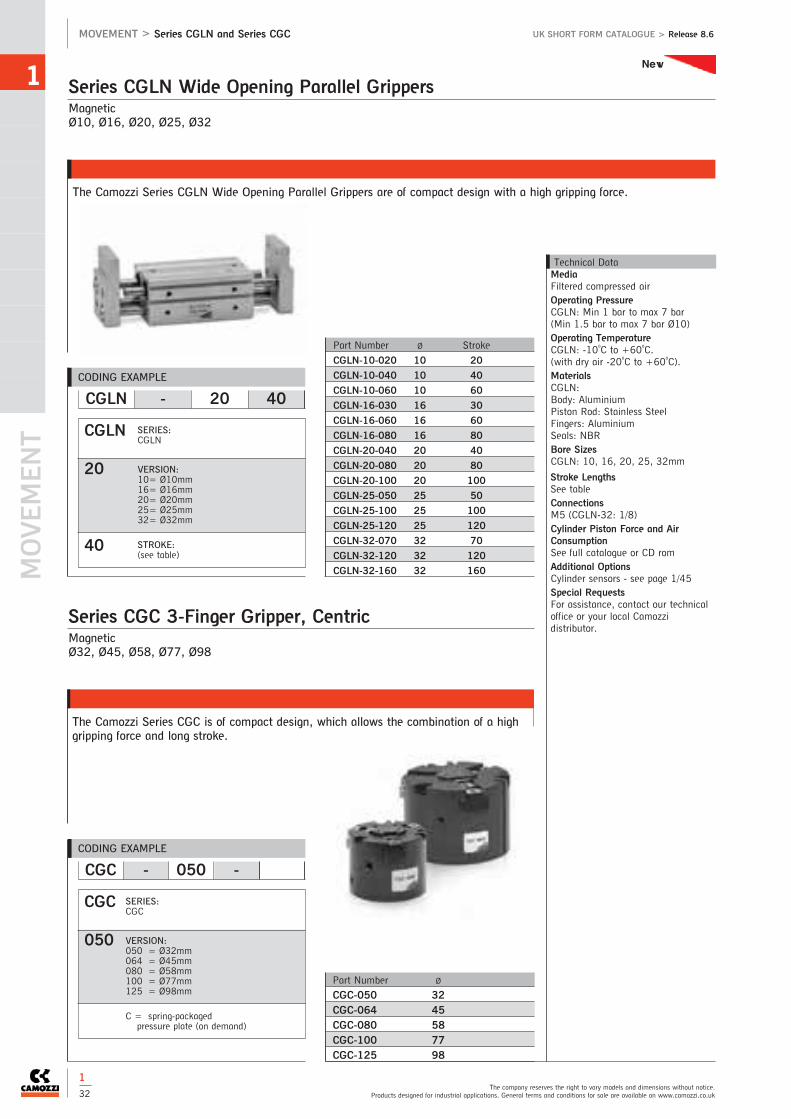
MOVEM
ENT
1
The company reserves the right to vary models and dimensions without notice.Products designed for industrial applications. General terms and conditions for sale are available on www.camozzi.co.uk
MOVEMENT > Series CGLN and Series CGC UK SHORT FORM CATALOGUE > Release 8.6
1
32
MagneticØ10, Ø16, Ø20, Ø25, Ø32
The Camozzi Series CGLN Wide Opening Parallel Grippers are of compact design with a high gripping force.
Series CGLN Wide Opening Parallel Grippers
Technical DataMediaFiltered compressed airOperating PressureCGLN: Min 1 bar to max 7 bar (Min 1.5 bar to max 7 bar Ø10)Operating TemperatureCGLN: -10oC to +60oC. (with dry air -20oC to +60oC).MaterialsCGLN:Body: AluminiumPiston Rod: Stainless SteelFingers: AluminiumSeals: NBRBore SizesCGLN: 10, 16, 20, 25, 32mm
Stroke LengthsSee tableConnectionsM5 (CGLN-32: 1/8)Cylinder Piston Force and AirConsumptionSee full catalogue or CD romAdditional OptionsCylinder sensors - see page 1/45Special RequestsFor assistance, contact our technicaloffice or your local Camozzidistributor.
Part Number Ø Stroke
CGLN-10-020 10 20
CGLN-10-040 10 40
CGLN-10-060 10 60
CGLN-16-030 16 30
CGLN-16-060 16 60
CGLN-16-080 16 80
CGLN-20-040 20 40
CGLN-20-080 20 80
CGLN-20-100 20 100
CGLN-25-050 25 50
CGLN-25-100 25 100
CGLN-25-120 25 120
CGLN-32-070 32 70
CGLN-32-120 32 120
CGLN-32-160 32 160
Part Number Ø
CGC-050 32CGC-064 45CGC-080 58CGC-100 77CGC-125 98
MagneticØ32, Ø45, Ø58, Ø77, Ø98
The Camozzi Series CGC is of compact design, which allows the combination of a highgripping force and long stroke.
Series CGC 3-Finger Gripper, Centric
CODING EXAMPLE
CGLN - 20 40
CGLN
20
40
SERIES:CGLN
VERSION:10= Ø10mm16= Ø16mm20= Ø20mm25= Ø25mm32= Ø32mm
STROKE:(see table)
CODING EXAMPLE
CGC - 050 -
CGC
050
SERIES:CGC
VERSION:050 = Ø32mm064 = Ø45mm080 = Ø58mm100 = Ø77mm125 = Ø98mm
C = spring-packaged pressure plate (on demand)
New

1
See full catalogue or CD rom for all dimensions.For technical advice contact our sales office or your local Camozzi distributor.
UK SHORT FORM CATALOGUE > Release 8.6 MOVEMENT > Series 50
1
33
Double-acting, MagneticØ16, Ø25, Ø32, Ø40, Ø50, Ø63, Ø80
Series 50 Rodless Cylinders
Technical DataType of ConstructionRodless with integral carriageMediaCompressed air (filtered), with orwithout lubricationOperating PressureMin 1 bar to max 8 bar Operating Temperature0oC to +50oC. (with dry air -10oC to +50oC)MaterialsBody: AluminiumSeals: Polyurethane and NBREnd covers: AluminiumPiston and Barrel: AluminiumCushioningAdjustable pneumatic cushioningBore Sizes16, 25, 32, 40, 50, 63, 80mm
Stroke LengthsOn request, max. 4000mmSpeedMin 10mm/sec. (no load)Max 1000mm/sec. (no load)ConnectionsØ16 - M5Ø25 - 1/8Ø32, Ø40, Ø50 - 1/4Ø63 - 3/8Ø80 - 1/2MountingsFoot mountedCylinder Piston Force and AirConsumptionRefer to appendix pages 17-20Cylinder Breakdown ServiceSame day breakdown service on allstandard and non-standard cylindersAdditional OptionsCylinder sensors - see page 1/44Seal Kits available on requestSpecial RequestsFor assistance, contact our technicaloffice or your local Camozzidistributor
Series 52 Rodless cylinders alsoavailable.Please see page 1/35 for more details
Note: All accessories are supplied separately.
Series 50 Cylinder Accessories
CODING EXAMPLE
50 M 2 P 50 A 0500
50
M
2
P
50
A
0500
SERIES:50
VERSION:M = magnetic standard
OPERATION:2 = double-acting cushioned
standard carriage
MATERIALS:P = anodized AL profile tube - PU and
NBR seals - standard carriageU = anodized AL profile tube - PU and
NBR seals - flanged carriage
BORE:16, 25, 32, 40, 50, 63, 80mm
TYPE OF MOUNTINGA = standardB = feetBH = intermediate feetCF = floating bracket
STROKE:Min 100mm - Max 4000mm
Foot Mounts (pair)
Ø
B-50-16 16
B-50-25 25
B-50-32 32
B-50-40 40
B-50-50 50
B-50-63 63
B-50-80 80
Floating Bracket
Ø
CF-50-25 25
CF-50-32 32
CF-50-40 40
CF-50-50 50
CF-50-63 63
CF-50-80 80
For Magnetic Proximity Switches
See pages 1/44 and 45
Intermediate Foot Mounts
Ø
BH-50-16 16
BH-50-25 25
BH-50-32 32
BH-50-40 40
BH-50-50 50
BH-50-63 63
BH-50-80 80
SAME
DAY

MOVEM
ENT
1
The company reserves the right to vary models and dimensions without notice.Products designed for industrial applications. General terms and conditions for sale are available on www.camozzi.co.uk
MOVEMENT > Series 50 UK SHORT FORM CATALOGUE > Release 8.6
Max. load Max. bending torque Max. bending torque Torsional torquepermitted force permitted force permitted force permitted
(N) (Nm) (Nm) (Nm)
Øcyl. L M Ms Mv
16 218 3.1 0.5 1
25 660 12.4 1.9 5
32 720 30 4 8
40 1370 39 4 9
50 1600 122 11 16
63 2210 190 19 26
80 3770 305 30 47
Note: Loads and bending torque are valid if applied separately.
Note: The charts below have been made according to a max. distance of 0.5 mmLoad (N).Once the load and the cylinder diameter have been fixed, the charts reported belowgive the k values beyond which it is necessary to put an intermediate feet.
M =F x bMS =F x bMV =F x b
Maximum Permitted Loads and Torque Forces
Loads According to Supports’ Distance
1
34

1
See full catalogue or CD rom for all dimensions.For technical advice contact our sales office or your local Camozzi distributor.
UK SHORT FORM CATALOGUE > Release 8.6 MOVEMENT > Series 52
1
35
Double-acting, Magnetic, cushionedØ25, Ø32, Ø40, Ø50, Ø63
Series 52 Rodless Cylinders
Technical DataType of ConstructionRodless with integral carriageMediaCompressed air (filtered), with orwithout lubricationOperating PressureMin 1 bar to max 8 bar Operating Temperature0oC to +50oC. (with dry air -10oC to +50oC)MaterialsBody: AluminiumSeals: Polyurethane and NBREnd covers: AluminiumPiston and Barrel: AluminiumCushioningAdjustable pneumatic cushioningBore Sizes25, 32, 40, 50, 63mm
Stroke LengthsOn request, max. 4000mmSpeedMin 10mm/sec. (no load)Max 1000mm/sec. (no load)ConnectionsØ25 - 1/8Ø32, Ø40, Ø50 - 1/4Ø63 - 3/8MountingsFoot mountedCylinder Piston Force and AirConsumptionRefer to appendix pages 17-20Additional OptionsCylinder sensors - see page 1/44Seal Kits available on requestSpecial RequestsFor assistance, contact our technicaloffice or your local Camozzidistributor.
For full dimensional details pleasecontact our sales office
Intermediate Foot Mounts
Ø
B-52-25 25
B-52-32 25
B-52-40 32
B-52-50 40
B-52-63 50
Intermediate Bracket
Ø
BH-52-25 25
BH-52-32 32
BH-52-40 40
BH-52-50 50
BH-52-63 63
Self-compensating Adaptor
Ø
CF-52-25-32 25
CF-52-25-32 32
CF-52-40 40
CF-52-50-63 50
CF-52-50-60 63
Note: All accessories are supplied separately.
Series 52 Cylinder Accessories
Foot Mounts for use for with BH
Ø
BA-52-25 25
BA-52-32 32
BA-52-40 40
BA-52-50 50
BA-52-63 63
CODING EXAMPLE
52 M 2 P 40 A 0500
52
M
2
P
40
A
0500
SERIES:52
VERSION:M = standardG = with slide bearingR = with roller bearing
(only Ø25 - 32 - 40)
OPERATION:2 = double-acting, cushioned8 = double-acting, cushioned, with air
supply from one side only
MATERIALS:P = anodised AL profile tube, NBR andPolyurethane seals, standard carriage C = anodised AL profile, NBR andPolyurethane seals, short carriage
BORE:25, 32, 40, 50, 63mm
TYPE OF MOUNTING:A = standard
STROKE:Up to 6000mm

MOVEM
ENT
1
The company reserves the right to vary models and dimensions without notice.Products designed for industrial applications. General terms and conditions for sale are available on www.camozzi.co.uk
MOVEMENT > Series 52 UK SHORT FORM CATALOGUE > Release 8.6
Table showing the maximum permitted loads and torque forces
Part Number L Max Ls Max M Max Ms Max Mv Max Mass at 0 mm Additional mass
(N) (N) (Nm) (Nm) (Nm) stroke (kg) per 100 mm (kg)
52M2P25A - 52M8P25A 270 - 13 2.5 11 0.88 0.30
52M2C25A - 52M8C25A 270 - 8 2 7 0.62 0.30
52G2P25A - 52G8P25A 580 580 23 10 23 1.31 0.30
52G2C25A - 52G8C25A 340 340 9 5 9 0.88 0.30
52R2P25A - 52R8P25A 850 1300 65 35 105 1.97 0.42
52R2C25A - 52R8C25A 850 1300 29 35 64 1.33 0.42
52M2P32A - 52M8P32A 300 - 30 3 24 1.40 0.39
52M2C32A - 52M8C32A 300 - 15 3 12 0.96 0.39
52G2P32A - 52G8P32A 850 850 33 15 33 2.09 0.39
52G2C32A - 52G8C32A 460 460 14 6.5 14 1.35 0.39
52R2P32A - 52R8P32A 900 1500 79 40 125 2.96 0.48
52R2C32A - 52R8C32A 900 1500 36 40 76 1.91 0.48
Table showing the maximum permitted loads and torque forces
Part Number L Max Ls Max M Max Ms Max Mv Max Mass at 0 mm Additional mass
(N) (N) (Nm) (Nm) (Nm) stroke (kg) per 100 mm (kg)
52M2P40A - 52M8P40A 650 - 60 4 54 2.41 0.52
52M2C40A - 52M8C40A 650 - 30 4 27 1.65 0.52
52G2P40A - 52G8P40A 1120 1120 60 25 60 3.58 0.52
52G2C40A - 52G8C40A 600 600 25 11 25 2.30 0.52
52R2P40A - 52R8P40A 1200 2000 190 67 118 5.89 0.74
52R2C40A - 52R8C40A 1200 2000 85 67 72 3.84 0.74
52M2P50A - 52M8P50A 800 - 80 17 74 5.30 0.96
52M2C50A - 52M8C50A 800 - 38 17 32 3.50 0.96
52G2P50A - 52G8P50A 1550 1500 200 70 200 7.28 0.96
52G2C50A - 52G8C50A 820 800 60 40 60 4.63 0.96
52M2P63A - 52M8P63A 1400 - 110 17 100 8.10 1.32
52M2C63A - 52M8C63A 1400 - 50 17 48 5.40 1.32
52G2P63A - 52G8P63A 2200 2000 300 102 300 11.02 1.32
52G2C63A - 52G8C63A 1100 1100 105 56 105 7.10 1.32
Loads and Torque Forces Ø25, Ø32
Loads and Torque Forces Ø40, Ø50, Ø63
1
36
COMPLEX LOADSIf more than one force and torque is appliedsimultaneously, they have to be calculatedaccording to the following formula:L/L (max)+ Ls/Ls (max)+ M/M (max)+ Ms/Ms(max)+ Mv/Mv (max ) ≤1.For models 52M, the load and torque values referto the center of the tube. For models 52G/52R theload and torque values refer to the centre point ofthe external guide. It is also necessary for thesemodels to guarantee on the fixing surface a max0.1 flatness’s value.The load and torque values refer to a velocity of:Models 52M/52G/52M/52G ≤ 0.2 m/s, models52R ≤ 2 m/s.
COMPLEX LOADSIf more than one force and torque is appliedsimultaneously, they have to be calculatedaccording to the following formula:L/L (max)+ Ls/Ls (max)+ M/M (max)+ Ms/Ms(max)+ Mv/Mv (max ) ≤1.For models 52M, the load and torque values referto the centre of the tube. For models 52G/52R theload and torque values refer to the center point ofthe guide.The load and torque values refer to a velocity of:Models 52M/52G ≤0.2 m/s Models 52R ≤2 m/sIf the velocity exceeds 0.2m/s for the models52M/52G, the load and torque values have to bemultiplied by the coefficients according to the table.

1
See full catalogue or CD rom for all dimensions.For technical advice contact our sales office or your local Camozzi distributor.
UK SHORT FORM CATALOGUE > Release 8.6 MOVEMENT > Series 52
1
37
End Cushion Diagram
Loads According to Supports Distance
The end cushion regulating screw has to be regulated to obtaina smooth movement at the end of stroke.In those applications which have different values than the onesstated in the diagram, external shock-absorbers have to be used.The shock-absorber should be centrally located with respect tothe centre of the mass.The diagram applies for horizontal operations.
Correction coefficient, loadsspeed - coefficient:0.2 m/s - 10.3 m/s - 0.750.4 m/s - 0.50.5 m/s - 0.40.75 m/s - 0.271 m/s - 0.2
DEFLECTION 0.5 mmThe charts have been made according to a max.deflection of0.5 mm and 1 mm when a load (N) is applied.The charts give the max distance between twosupports in orderto stay within the deflection range given.
DEFLECTION 1 mmThe charts have been made according to a max.deflection of0.5 mm and 1 mm when a load (N) is applied.The charts give the max distance between twosupports in orderto stay within the deflection range given.

MOVEM
ENT
1
The company reserves the right to vary models and dimensions without notice.Products designed for industrial applications. General terms and conditions for sale are available on www.camozzi.co.uk
MOVEMENT > Series 90 UK SHORT FORM CATALOGUE > Release 8.6
1
38
Single and double-acting, cushioned, magnetic Ø32, Ø40, Ø50, Ø63, Ø80, Ø100, Ø125 ISO 15552 - DIN/ISO 6431 - VDMA 24562
Series 90 Stainless Steel Cylinders AISI 316
Technical DataType of ConstructionPiston cylinder with tie-rods.Single-acting, double-acting andthrough-rod. Magnetic as standardMediaCompressed air (filtered), with orwithout lubricationOperating PressureMin 1 bar to max 10 barOperating Temperature0oC to +80oC. (with dry air -20oC to +80oC)MaterialsStainless Steel AISI 316, (SS 2343)end blocks, barrel, piston rod, tie rodand NBR sealsCushioningEnd of stroke buffers with adjustablepneumatic cushioningBore Sizes32, 40, 50, 63, 80, 100, 125mm
Stroke LengthsStandard - see tablesNon-standard - on requestSpeedMin 10mm/sec. (no load)Max 1000mm/sec. (no load)ConnectionsØ32 - 1/8Ø40, Ø50 - 1/4Ø63, Ø80 - 3/8Ø100, Ø125 - 1/2MountingsComprehensive range of ISO/VDMAAISI 303/304 mounting brackets - see page 1/39Cylinder Piston Force and AirConsumptionRefer to appendix pages 17-20Additional OptionsCylinder sensors - see page 1/44Piston rod accessories - see page 1/39Viton seals**Non-standard available only onrequestSeal Kits available on requestSpecial RequestsFor assistance, contact our technicaloffice or your local Camozzidistributor.
NOTE: Rod nuts and accessories are supplied separately
Double-acting (through rod and non-standard strokes available on request)
■ Double-acting
Ø32 Ø40 Ø50 Ø63 Ø80 Ø100 Ø125
Standard Stroke
25 ■ ■ ■ ■ ■ ■
50 ■ ■ ■ ■ ■ ■ ■
75 ■ ■ ■ ■ ■ ■ ■
80 ■ ■ ■ ■ ■ ■ ■
100 ■ ■ ■ ■ ■ ■ ■
125 ■ ■ ■ ■ ■ ■ ■
150 ■ ■ ■ ■ ■ ■ ■
160 ■ ■ ■ ■ ■ ■ ■
200 ■ ■ ■ ■ ■ ■ ■
250 ■ ■ ■ ■ ■ ■ ■
300 ■ ■ ■ ■ ■ ■ ■
320 ■ ■ ■ ■ ■ ■ ■
400 ■ ■ ■ ■ ■ ■ ■
500 ■ ■ ■ ■ ■ ■ ■
CODING EXAMPLE
STANDARD STROKES FOR CYLINDERS SERIES 90
90 M 2 A 050 A 0200 -
90
M
2
A
050
A
0200
-
SERIES:90
VERSION:M = standard, magnetic
OPERATION:1 = single-acting (front spring)2 = double-acting (front and rear cushions)6 = double-acting
(through-rod with front and rear cushions)
MATERIALS:A = Stainless Steel AISI 316
(SS 2343), NBR sealsV = Stainless Steel AISI 316
(SS 2343), viton seals
BORE:32, 40, 50, 63, 80, 100, 125mm
TYPE OF DESIGN:A = tie-rods
STROKE:(see table)
SPECIAL: to be specifiedV = rod seals viton

1
See full catalogue or CD rom for all dimensions.For technical advice contact our sales office or your local Camozzi distributor.
UK SHORT FORM CATALOGUE > Release 8.6 MOVEMENT > Series 90
1
39
Rear Trunnion, Male
Ø
L-90-32 32
L-90-40 40
L-90-50 50
L-90-63 63
L-90-80 80
L-90-100 100
L-90-125 125
Stainless steel 304
Front and Rear Flange
Ø
D-E-90-32 32
D-E-90-40 40
D-E-90-50 50
D-E-90-63 63
D-E-90-80 80
D-E-90-100 100
D-E-90-125 125
Stainless steel 304
Rear Trunnion, Female
Ø
C-H-90-32 32
C-H-90-40 40
C-H-90-50 50
C-H-90-63 63
C-H-90-80 80
C-H-90-100 100
C-H-90-125 125
Stainless steel 304
Foot Mounts (pair)
Ø
B-90-32 32
B-90-40 40
B-90-50 50
B-90-63 63
B-90-80 80
B-90-100 100
B-90-125 125
Stainless steel 304
Clevis Pin
Ø
S-90-32 32
S-90-40 40
S-90-50 50
S-90-63 63
S-90-80 80
S-90-100 100
S-90-125 125
Stainless steel 303
90O Swivel Trunnion
(to CETOP RP 107P) Ø
ZC-90-32 32
ZC-90-40 40
ZC-90-50 50
ZC-90-63 63
ZC-90-80 80
ZC-90-100 100
ZC-90-125 125
Stainless steel 304
Front Trunnion, Female
Ø
C+L+S-90-32 32
C+L+S-90-40 40
C+L+S-90-50 50
C+L+S-90-63 63
C+L+S-90-80 80
C+L+S-90-100 100
C+L+S-90-125 125
Stainless steel 304
For FRL’s
See 3 (Treatment)
Piston Rod Lock Nut
Ø
U-90-25-32 32
U-90-40 40
U-90-50-63 50-63
U-90-80-100 80-100
U-90-125 125
Stainless steel 304, UNI 5589
For Magnetic Proximity Switches
See pages 1/44 and 45
Swivel Ball Joint
Ø
GA-90-25-32 32
GA-90-40 40
GA-90-50-63 50-63
GA-90-80-100 80-100
GA-90-125 125
Stainless steel 304, ISO 8139
Series 90 Accessories
Rod Fork End
Ø
G-90-25-32 32
G-90-40 40
G-90-50-63 50-63
G-90-80-100 80-100
G-90-125 125
Stainless steel 303, ISO 8140

MOVEM
ENT
1
The company reserves the right to vary models and dimensions without notice.Products designed for industrial applications. General terms and conditions for sale are available on www.camozzi.co.uk
MOVEMENT > Series 94 and 95 UK SHORT FORM CATALOGUE > Release 8.6
1
40
Single and double-acting, magnetic - CETOP RP52-P DIN/ISO 6432Series 94: Ø16, Ø20, Ø25Series 95: Ø25, cushioned
Series 94 and 95 Stainless Steel Mini-Cylinders AISI 316
Technical DataType of ConstructionCompact - Flanged Magnetic as standardMediaCompressed air (filtered), with orwithout lubricationOperating PressureMin 1 bar to max 10 barOperating Temperature0oC to +80oC. (with dry air -20oC to +80oC)MaterialsStainless Steel AISI 316end blocks, barrel, piston rod andNBR sealsØ16-25 barrel AISI 304CushioningSeries 94 - end of stroke buffersSeries 95 - end of stroke buffers withadjustable pneumatic cushioningBore Sizes16, 20, 25mm
Stroke LengthsStandard - see tablesNon-standard - on requestSpeedMin 10mm/sec. (no load)Max 500mm/sec. (no load)ConnectionsØ16 - M5Ø20, Ø25 - 1/8MountingsComprehensive range of ISO/VDMAAISI 303/304 mounting brackets -see page 1/41Cylinder Piston Force and AirConsumptionRefer to appendix pages 17-20Additional OptionsCylinder sensors - see page 1/44Piston rod accessories - see page 1/41Viton seals**Non-standard available only onrequestSeal Kits available on requestSpecial RequestsFor assistance, contact our technicaloffice or your local Camozzidistributor.
NOTE: Accessories are supplied separately
Double-acting and Single-acting (through rod and non-standard strokes available on request)
Series 94 94 94 95
Ø16 Ø20 Ø25 Ø25
Standard Stroke
10 ■ ✖ ■ ✖ ■ ✖ ■
25 ■ ✖ ■ ✖ ■ ✖ ■
40 ■ ✖ ■ ✖ ■ ✖ ■
50 ■ ✖ ■ ✖ ■ ✖ ■
80 ■ ■ ■ ■
100 ■ ■ ■ ■
125 ■ ■ ■ ■
160 ■ ■ ■ ■
200 ■ ■ ■ ■
250 ■ ■ ■
300 ■ ■ ■
320 ■ ■
400 ■ ■
500 ■ ■
CODING EXAMPLE
STANDARD STROKES FOR CYLINDERS SERIES 94 AND 95
94 N 2 A 16 A 100 -
94
N
2
A
16
A
100
-
SERIES:94= magnetic95= magnetic, cushioned
VERSION:N = standard, magnetic
OPERATION:1 = single-acting (front spring)2 = double-acting3 = double-acting
(through-rod)
MATERIALS:A = Stainless Steel AISI 316
viton rod seals others NBRV = Stainless Steel AISI 316
all viton seals
BORE:16, 20, 25mm
TYPE OF DESIGN:A = standard (locking ring for end
cap + lock nut for rod)
STROKE:(see table)
SPECIAL: to be specifiedV = rod seals viton
■ Double-acting✖ Single-acting

1
See full catalogue or CD rom for all dimensions.For technical advice contact our sales office or your local Camozzi distributor.
UK SHORT FORM CATALOGUE > Release 8.6 MOVEMENT > Series 94 and 95
1
41
Rod Fork End
Ø
G-94-12-16 16
G-94-20 20
G-90-25-32 25
Stainless steel 303
Foot Mounts (pair)
Ø
B-94-12-16 16
B-94-20-25 20-25
Stainless steel 304
Front/Rear Flange Mount
Ø
E-94-12-16 16
E-94-20-25 20-25
Stainless steel 304
Rear Trunnion Bracket
Ø
I-94-12-16 16
I-94-20-25 20-25
Stainless steel 304
For Magnetic Proximity Switches
See pages 1/44 and 45
Swivel Ball Joint
Ø
GA-94-12-16 16
GA-94-20 20
GA-90-25-32 25
Stainless steel 304
Piston Rod Lock Nut
Ø
U-94-12-16 16
U-94-20 20
U-90-25-32 25
Stainless steel 304
Nose Nut
Ø
U-90-50-63 16
V-94-20-25 20-25
Stainless steel 304
Series 94-95 Accessories
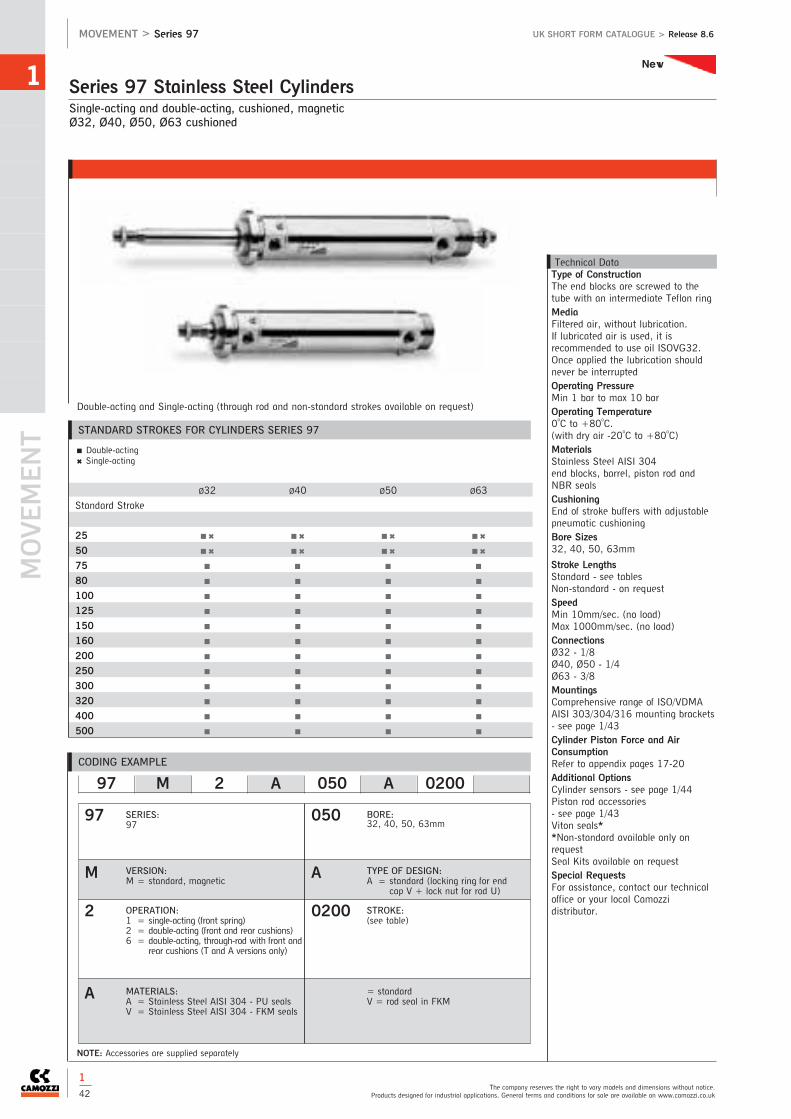
MOVEM
ENT
1
The company reserves the right to vary models and dimensions without notice.Products designed for industrial applications. General terms and conditions for sale are available on www.camozzi.co.uk
MOVEMENT > Series 97 UK SHORT FORM CATALOGUE > Release 8.6
1
42
Single-acting and double-acting, cushioned, magneticØ32, Ø40, Ø50, Ø63 cushioned
Series 97 Stainless Steel Cylinders
Technical DataType of ConstructionThe end blocks are screwed to thetube with an intermediate Teflon ringMediaFiltered air, without lubrication. If lubricated air is used, it isrecommended to use oil ISOVG32.Once applied the lubrication shouldnever be interrupted Operating PressureMin 1 bar to max 10 barOperating Temperature0oC to +80oC. (with dry air -20oC to +80oC)MaterialsStainless Steel AISI 304end blocks, barrel, piston rod andNBR sealsCushioningEnd of stroke buffers with adjustablepneumatic cushioningBore Sizes32, 40, 50, 63mm
Stroke LengthsStandard - see tablesNon-standard - on requestSpeedMin 10mm/sec. (no load)Max 1000mm/sec. (no load)ConnectionsØ32 - 1/8Ø40, Ø50 - 1/4Ø63 - 3/8MountingsComprehensive range of ISO/VDMAAISI 303/304/316 mounting brackets- see page 1/43Cylinder Piston Force and AirConsumptionRefer to appendix pages 17-20Additional OptionsCylinder sensors - see page 1/44Piston rod accessories - see page 1/43Viton seals**Non-standard available only onrequestSeal Kits available on requestSpecial RequestsFor assistance, contact our technicaloffice or your local Camozzidistributor.
NOTE: Accessories are supplied separately
Double-acting and Single-acting (through rod and non-standard strokes available on request)
■ Double-acting✖ Single-acting
Ø32 Ø40 Ø50 Ø63
Standard Stroke
25 ■ ✖ ■ ✖ ■ ✖ ■ ✖
50 ■ ✖ ■ ✖ ■ ✖ ■ ✖
75 ■ ■ ■ ■
80 ■ ■ ■ ■
100 ■ ■ ■ ■
125 ■ ■ ■ ■
150 ■ ■ ■ ■
160 ■ ■ ■ ■
200 ■ ■ ■ ■
250 ■ ■ ■ ■
300 ■ ■ ■ ■
320 ■ ■ ■ ■
400 ■ ■ ■ ■
500 ■ ■ ■ ■
CODING EXAMPLE
STANDARD STROKES FOR CYLINDERS SERIES 97
97 M 2 A 050 A 0200
97
M
2
A
050
A
0200
SERIES:97
VERSION:M = standard, magnetic
OPERATION:1 = single-acting (front spring)2 = double-acting (front and rear cushions)6 = double-acting, through-rod with front and
rear cushions (T and A versions only)
MATERIALS:A = Stainless Steel AISI 304 - PU sealsV = Stainless Steel AISI 304 - FKM seals
BORE:32, 40, 50, 63mm
TYPE OF DESIGN:A = standard (locking ring for end
cap V + lock nut for rod U)
STROKE:(see table)
= standardV = rod seal in FKM
New

1
See full catalogue or CD rom for all dimensions.For technical advice contact our sales office or your local Camozzi distributor.
UK SHORT FORM CATALOGUE > Release 8.6 MOVEMENT > Series 97
1
43
Tight Rear Female Trunnion Bracket
Ø
CR-90-32 32
CR-90-40 40
CR-90-50 50
CR-90-63 63
Stainless steel 316
Trunnion
Ø
I-97-32 32
I-97-40 40
I-97-50 50
I-97-63 63
Stainless steel 304
Rear Female Trunnion Bracket
Ø
C-H-90-32 32
C-H-90-40 40
C-H-90-50 50
C-H-90-63 63
Stainless steel 316
Foot Mounts (pair)
Ø
B-97-32 32
B-97-40 40
B-97-50 50
B-97-63 63
Stainless steel 304
Male Trunnion Bracket with swivel Ball Joint
Ø
R-90-32 32
R-90-40 40
R-90-50 50
R-90-63 63
Stainless steel 316
Series 97 Accessories
Rod Fork End
Ø
G-90-25-32 32
G-90-40 40
G-90-50-63 50-63
Stainless steel 303, ISO 8140
90O Male Trunnion Bracket with Swivel Ball Joint
Ø
ZCR-90-32 32
ZCR-90-40 40
ZCR-90-50 50
ZCR-90-63 63
Stainless steel 316
Clevis Pin
Ø
S-90-32 32
S-90-40 40
S-90-50 50
S-90-63 63
Stainless steel 303
Swivel Ball Joint
Ø
GA-90-32 32
GA-90-40 40
GA-90-50-63 50-63
Stainless steel 304, ISO 8139
Nose Nut
Ø
V-97-32 32
V-97-40 40
V-97-50-63 50-63
Stainless steel 304
Piston Rod Lock Nut
Ø
U-90-25-32 32
U-90-40 40
U-90-63 50-63
Stainless steel 304, ISO 4035
Antirotating Clevis Pin
Ø
SR-90-32 32
SR-90-40 40
SR-90-50 50
SR-90-63 63
Stainless steel 304, ISO 8139
For Magnetic Proximity Switches
See pages 1/44 and 45
New

MOVEM
ENT
1
The company reserves the right to vary models and dimensions without notice.Products designed for industrial applications. General terms and conditions for sale are available on www.camozzi.co.uk
MOVEMENT > Series SKR-CSV UK SHORT FORM CATALOGUE > Release 8.6
1
44
The Camozzi Series SKR - CSV are designed to fit into the grooves provided in the profile barrel of “compact” and “rodless”cylinders or on the surface of roundline and tie rod cylinders by using mounting bands or brackets
Magnetic Proximity Switches and Brackets
32-63 80-100
Series Ø Part Number
24-25 16 SF16
24-25 20 SF20
24-25 25 SF25Bracket for use with T slot type switch
Series Ø Part Number
27 16 SF16
27 20 SF20
27 25 SF25
27 32 S-CST 06
27 40 S-CST 07
27 50 S-CST 08
27 63 S-CST 09Bracket for use with T slot type switch
Series Ø
31 12-100 Direct Mounting
Direct mounting with T slot type
switch, no bracket required
Series Ø
32 20-100 Direct Mounting
Direct mounting with T slot type switch,
no bracket required
Series Ø Part Number
60+45N 32-63 S-CST 45N1
60+45N 80-100 S-CST 45N2Bracket for use with T slot type switch
Series Ø
69 32 Direct MountingDirect mounting with T slot type switch,no bracket required
Series Ø
QP 12-16 Direct Mounting*
QP 20-100 SZR12**
QPR 12-16 Direct Mounting*
QPR 20-100 SZR12***with CSV type switch **with T slot type switch
10
,5
10
,5
729,1
10
,5
Series Ø
61 32-125 Direct MountingDirect mounting with T slot type switch,no bracket required
80-10032-63
Part Number Description
SKR2C01M8 T slot reed, 2 wires with M8 connector, 5 - 50v AC/DC
CSV-250N V slot reed, 2 wires with M8 connector, 10 - 110v AC/DC
SKR3C01M8 T slot reed, 3 wires with M8 connector, 5 - 30v AC/DC
CSV-262 V slot reed, 3 wires with M8 connector, 5 - 30v AC/DC
SKH3C01M8 T slot hall effect, 3 wires with M8 connector, PNP, 10 - 30v DC
CSV-362 V slot hall effect, 3 wires with M8 connector, PNP, 10 - 30v DC
AG08B3C25050 M8 female, 3 pole, 5m extension lead
Part Number Description
SKR2C01200 T slot reed, 2 wires, 5 - 130v AC/DC
CSV-220 V slot reed, 2 wires, 10 - 110v AC/DC
SKR3C01200 T slot reed, 3 wires, 5 - 30v AC/DC
CSV-232 V slot reed, 3 wires, 5 - 30v AC/DC
SKH3C01200 T slot hall effect, 3 wires, PNP, 10 - 30v DC
CSV-332 V slot hall effect, 3 wires, PNP, 10 - 27v DC
SKR6C01300 T slot reed, 2 wires, 5 - 230v AC/DC (3m cable)
Series Ø Part Number
42 32 S-CST 06
42 40 S-CST 07
42 50 S-CST 08
42 63 S-CST 09Bracket for use with T slot type switch
Series Ø
52 25-63 Direct MountingDirect mounting with T slot typeswitch, no bracket required
Series Ø Part Number
60 32-63 SCT32
60 80-100 SCT80
60 125 S-CST 27
40 160-200 S-CST 28Bracket for use with T slot type switch
Series Ø Part Number
50 16-25 Direct Mounting*
50 32-80 SZR12***with CSV type switch **with T slot type switch
Note: 2 & 3 wire reed switches listed are N.O. with a 2 metre long cable. Alternatives can be quoted on request. Reed switches fitted with an M8 connector areN.O. with a 0.3 metres long cable.For the correct function of Proximity Switches they must only be used with the relevant bracket where applicable.

1
See full catalogue or CD rom for all dimensions.For technical advice contact our sales office or your local Camozzi distributor.
UK SHORT FORM CATALOGUE > Release 8.6 MOVEMENT > Series CSB - CSC
1
45
Reed SwitchThe Camozzi Series CSB - CSC Magnetic Proximity Switch define the position of the magnetic piston. When the internalcontact is actuated by a magnetic field, the sensors complete an electrical circuit and provide an output signal to actuatedirectly a solenoid valve or a PLC.
Series CSB - CSC Magnetic Proximity Switches
Technical DataOperating Temperature-10oC to +60oCMaterialsBody: Plastic encapsulating epoxyresinMountingsDirectly into the groovesSpecial RequestsFor assistance, contact our technicaloffice or your local Camozzidistributor.
Part Number
CSB-D-220
CSB-H-220
CSC-D-220
CSC-H-220
*CSB type suit CGA, CGB, CGC and CGP type grippers.
**CSC type suit CGLN, CGSN and QX type grippers.
Part Number
CSN-2032-0
Part Number
S21 For cylinders series 40 Ø160, Ø200, Ø250
S53 For cylinders series 41 Ø160, Ø200
Series CSN Magnetic Proximity Switches
CODING EXAMPLE
CS B - D 2 2 0
CS
B
D
2
20
SERIES:CS = Magnetic
B = Square shapeC = Round shape
D = straight leadH = lead 90°
2 = reed
2 = 2 wires (only reed)
Technical DataOperating Temperature-25oC to +75oCMaterialsGlass reinforced nylonMountingsBracket for tie rod Ø6 - Ø10VoltageFor 12 to 220V AC and DCProtectionIP54/IP65 with connector DIN43650SignallingIntergrated red LED
Electrical ConnectionDIN 43650 connector, model KB132000139Max Current1.5 AMax Load20 W DC - 30 VA ACActuating Time≤ 2 msActuating Tolerance± 1mmType of ContactNO (normally open)

MOVEM
ENT
1
The company reserves the right to vary models and dimensions without notice.Products designed for industrial applications. General terms and conditions for sale are available on www.camozzi.co.uk
MOVEMENT > Series 43 UK SHORT FORM CATALOGUE > Release 8.6
1
46
Skip - Stop FunctionØ40
The Camozzi series 43 comes complete with an oil surge tank which ensures automatic equalisation.Speed variation is obtained by means of an incorporated flow regulator designed to allow comprehensive and constant use.
Series 43 Hydrochecks
Part Number
43N-LTB-40-50
43N-LTB-40-100
43N-LTB-40-150
43N-LTB-40-200
Part Number
43N-PTV-40-50
43N-PTV-40-100
43N-PTV-40-150
43N-PTV-40-200
Part Number
43N-LTO-40-50
43N-LTO-40-100
43N-LTO-40-150
43N-LTO-40-200
Part Number
43N-LTA-40-50
43N-LTA-40-100
43N-LTA-40-150
43N-LTA-40-200
Part Number
43N-PTO-40-50
43N-PTO-40-100
43N-PTO-40-150
43N-PTO-40-200
Part Number
43N-PSA-40-50
43N-PSA-40-100
43N-PSA-40-150
43N-PSA-40-200
Part Number
43N-PSV-40-50
43N-PSV-40-100
43N-PSV-40-150
43N-PSV-40-200
Part Number
43N-LTV-40-50
43N-LTV-40-100
43N-LTV-40-150
43N-LTV-40-200
Part Number
43N-PTB-40-50
43N-PTB-40-100
43N-PTB-40-150
43N-PTB-40-200
Part Number
43N-PSO-40-50
43N-PSO-40-100
43N-PSO-40-150
43N-PSO-40-200
Part Number
43N-PSB-40-50
43N-PSB-40-100
43N-PSB-40-150
43N-PSB-40-200
Technical DataType of ConstructionWith tie-rods MediaSpecial hydraulic oil (contact ourengineers)Operating PressureMin 1 max 10 barOperating Temperature-10oC to +70oCBore Size40mmStroke LengthsStandard - see tablesNon-standard - on requestSpeedMin 14mm/minMax 15mm/min (in non regulated direction)Controllable LoadMax 500kg (Including inertia of moving masses)Special RequestsFor assistance, contact our technicaloffice or your local CamozzidistributorNoteControllable load 500kg max (including inertia of moving).
Part Number
43N-PTA-40-50
43N-PTA-40-100
43N-PTA-40-150
43N-PTA-40-200

1
See full catalogue or CD rom for all dimensions.For technical advice contact our sales office or your local Camozzi distributor.
UK SHORT FORM CATALOGUE > Release 8.6 MOVEMENT > Series 43
1
47
Part Number Mounting Bracket
PCV-32 32 for mounting valves series 4, 1/4
PCV-40-50 40 - 50 for mounting valves series 4, 1/4
PCV-63-80 63 - 80 for mounting valves series 4, 1/4
Part Number Mounting Bracket
PCV-61-K3 for mounting solenoid valves Series 3, 1/8
PCV-61-K4 for mounting solenoid valves Series 4, 1/4
PCV-61-K8 for mounting solenoid valves Series 4, 1/8
PCV-61-KE for mounting solenoid valves Series E
Part Number A B C D E F G H I J K L M N O P Q R S
43N-40-40 60 - 110 26.5 56 - 12 7 19 47 M12 x 1.25 24 14 80 25 25 14 12 40
43N-40-50 70 60 122 32.52 62 57 12 9 24 65 M16 x 1.5 32 20 88 32 25 14 14 40
43N-40-63 80 60 132 37.5 67 57 20 9 24 65 M16 x 1.5 32 20 93 32 25 14 14 40
43N-40-80 100 60 152 47.5 77 57 20 11 30 78 M20 x 1.5 40 25 107 - - - 18 50
Note: Fittings and valve supplied separately Note: Fittings and valve supplied separately
Example of assembly Series 60 Example of assembly Series 61
Accessories for Hydrochecks Series 43 - Connecting Kit
CODING EXAMPLE
SERIES: 43
N = standardS = special
43 N - P S O - 40 - 200
43N
P
S
O
40
200
S = thrust (rod return regulated)T = traction (rod thrust regulated)
BORE:40mm
L = tank in seriesP = tank parallel
A = SKIP valveB = SKIP + STOP valveV = STOP valve0 = standard
STROKE in mm
Part Number 43N-PNP. Pump for refilling hydrocheck speed regulator
Series 60/61 Valve Mounting Bracket

MOVEM
ENT
1
The company reserves the right to vary models and dimensions without notice.Products designed for industrial applications. General terms and conditions for sale are available on www.camozzi.co.uk
MOVEMENT > Series RL UK SHORT FORM CATALOGUE > Release 8.6
1
48
Ø20, Ø25, Ø32, Ø40, Ø50, Ø63, Ø80, Ø100, Ø125 For ISO 6431/VDMA and ISO 6432 cylindersThe Camozzi Series RL are of compact dimensions allowing units to be fitted on cylinders where space is limited.
Series RL Rod Locks
Technical DataType of ConstructionCompact Operating PressureMin 3 max 10 barOperating Temperature0oC to +80oC. (with dry air 0oC to -80oC)MaterialsHousing: anodised aluminiumClamp: BrassSeals: NBRCylinder diameterØ20, Ø32, Ø40, Ø50, Ø63, Ø80, Ø100, Ø125
ConnectionsØ20, Ø25, Ø32 - M5Ø40, Ø50, Ø63, Ø80, Ø100, Ø125 - 1/8Special RequestsFor assistance, contact our technicaloffice or your local CamozzidistributorNoteCylinders must be ordered with apiston rod extension in order to fit rodlocks. See table
Caution!The rod lock should not beused to “brake’ the piston rodin dynamic conditions andmust only be applied whenmovement has ceased.
Standard, complete with cartridge and housing
RLC-24-20
RLC-24-25
RLC-41-32
RLC-41-40
RLC-41-50
RLC-41-63
RLC-41-80
RLC-41-100
RLC-41-125
Cartridge only
RLB-24-20
RLB-24-25
RLB-41-32
RLB-41-40
RLB-41-50
RLB-41-63
RLB-41-80
RLB-41-100
RLB-41-125
Ø 20 25 32 40 50 63 80 100 125holdingforce N. 300 400 650 1100 1600 2500 4000 6300 8800
HOLDING FORCE (STATIC LOAD)
Ø 20 25 32 40 50 63 80 100 125extension +46 +46 +40 +43 +57 +57 +80 +80 +125
MINIMUM OPERATIONAL STROKES
Pneumatic control Electropneumatic control
Scheme of Operation
CODING EXAMPLE
SERIESRLC = standard, complete with
cartridge and housing RLB = cartridge only
RLC - 41 - 32
RLC 41 32CYLINDER SERIES24= for Series 24 and 2541= for Series 60 and 61
CYLINDER BORE 20, 25, 32, 40, 50, 63, 80, 100, 125mm

1
See full catalogue or CD rom for all dimensions.For technical advice contact our sales office or your local Camozzi distributor.
UK SHORT FORM CATALOGUE > Release 8.6 MOVEMENT > Series SA
1
49
Self compensatingM8x1, M10x1, M12x1, M14x1.5, M20x1.5, M25x1.5, M27x1.5
The Camozzi Series SA Shock Absorbers are used to provide impact and noise absorption when stopping objects in motion
Series SA Shock Absorbers
Technical DataType of ConstructionHydraulic shock absorber, selfcompensating Operating Temperature-10oC to +80oCMaterialsBody: Steel, black coatedPiston Rod: Carbon steel, chromeplatedPiston: Carbon steelSeals: NBRStroke LengthsSee Shock absorbers coding SAMountingsThreaded BodySpecial RequestsFor assistance, contact our technicaloffice or your local Camozzidistributor.
Part Number Size Stroke
SA-0806 W M8x1 6mm
SA-0806 M8x1 6mm
SA-1007 W M10x1 7mm
SA-1007 M10x1 7mm
SA-1210 W M12x1 10mm
SA-1210 M12x1 10mm
SA-1412 W M14x1.5 12mm
SA-1412 M14x1.5 12mm
SA-2015 W M20x1.5 15mm
SA-2015 M20x1.5 15mm
SA-2525 W M25x1.5 25mm
SA-2525 M25x1.5 25mm
SA-2725 W M27x1.5 25mm
SA-2725 M27x1.5 25mm
NOTE: The shock absorbers are supplied complete with 2 mounting nuts.
CODING EXAMPLE
SERIES:SA
SA 0806
SA 0806 SIZE/STROKE0806 = size M8x1
stroke 6 mm1007 = size M10x1
stroke 7 mm1210 = size M12x1
stroke 10 mm1412 = size M14x1,5
stroke 12 mm2015 = size M20x1,5
stroke 15 mm2525 = size M25x1,5
stroke 25 mm2725 = size M27x1,5
stroke 25 mm
OPTIONNone = Standard, with capW = Without cap*
* on request
ADJUSTED STROKE NUT
A = Initial positionB = Final position1 = Impact object2 = Adjusted stroke nut3 = Shock absorber4 = Fixing screw5 = Stroke6 = Stroke length
Mod. ØA B C D E FSA-08SC (for SA-0806) 10.5 14 9 M8X1 11 12.7SA-10SC (for SA-1007) 12 16 10 M10X1 13 14.7SA-12SC (for SA-1210) 14.5 20 13 M12X1 16 18.5SA-14SC (for SA-1412) 25.8 20 15 M14X1 19 21.9SA-20SC (for SA-2015) 27.8 35 20 M20X1.5 26 30SA-25SC (for SA-2525) 5.8 45 30 M25X1.5 32 37SA-27SC (for SA-2725) 20.7 65 50 M27X1.5 32 37


2 > Control
2 Solenoid Valves/Pneumatic Valves
Directly and Indirectly Operated 2/2 - 3/2 Solenoid Valves
2 / 52 Series 3Valve Island Plug-In
2 / 58 Series 3Fieldbus Valve Islands
2 / 61 Series Y Valve Islands
2 / 65 Series HValve Islands
2 / 69 Series FValve Islands
2 / 72 Series CP2, CC2, CD2Individual Fieldbus Node
2 / 74 Connectorsfor Valve Islands
2 / 2 Technical Data
2 / 23 Series E Valves and Solenoid Valves
2 / 28 Series ENValves and Solenoid Valves
2 / 33 Series 3 and 4Electropneumatically Operated Valves
2 / 39 Series 3 and 4PneumaticallyOperated Valves
2 / 44 Series 9Electropneumatically and Pneumatically Operated ValvesISO 5599/1
2 / 46 Series NANAMUR Valves
2 / 47 U7* - U7*EX - G7* - A8* G93 - H8*Solenoid Coils
2 / 48 Solenoid DIN ConnectorsSolenoids
Valve Islands
2 / 11 Series K8Directly OperatedMini-Solenoid Valves
2 / 12 Series KDirectly OperatedMini-Solenoid Valves
2 / 13 Series KNMini-Solenoid Valves
2 / 14 Series KNHigh FlowMini-Solenoid Valves
2 / 15 Series WDirectly OperatedMini-Solenoid Valves
2 / 16 Series PDirectly OperatedMini-Solenoid Valves
2 / 17 Series PNDirectly operatedMini-Solenoid Valves
2 / 18 Series PDDirectly Operated Solenoid Valves
2 / 19 Series PLDirectly Operated Solenoid Valves
2 / 20 Series ADirectly OperatedSolenoid Valves
2 / 21 Series 6Directly OperatedSolenoid Valves
2 / 22 Series CFBStainless SteelSolenoid Valves

2
2 / 88 Series SCU, MCU, SVU, MVU, SCO and MCO Flow Regulators
2 / 90 Series PSCU, PMCU, PSVU, PMVU, PSCO and PMCOFlow Regulators
2 / 91 Series GSCU, GMCU,GSVU, GMVU, GSCO and GMCOFlow Regulators
Automatic Valves
2 / 86 Series SCS, VNR, VSC and VSOAutomatic Valves
2 / 87 Series VBO and VBUBlocking Valves
Logic Valves
2 / 85 Series 2LBasic Logic ValvesPneumatically Operated AmplifierSender and Receiver Elements Silencers
2 / 98 Silencers Series 2901, 2903, 2921, 2931, 2938, 2939, SP, SCO and RSWSilencers
Proportional Technology
Mechanical and Manual Valves
2 / 76 Series 2Mechanically OperatedMinivalves
2 / 76 Series 1 and 3Mechanically OperatedValves
2 / 78 Series 3 and 4Mechanically OperatedSensor Valves
2 / 79 Series 2 and 3Pneumatic and Electrical - Foot Operated Pedal
2 / 80 Series 2Manually OperatedConsole Minivalves
2 / 82 Series 1, 3, 4 and VMSManually Operated Valves
2 / 84 Series 2Mini-Handle Valves
Flow Control Valves
2 / 92 Series TMCU, TMVU and TMCOFlow Regulators
2 / 92 Series RFU and RFOFlow Regulators
2 / 93 Series 28Flow Regulators
Flow Control Valves - continued
Pressure Switches and Vacuum Switches
2 / 94 Series PMAdjustable-Diaphragm Pressure Switches, Transducer and Pressure Indicator
2 / 95 Series SWMElectronic Miniature Vacuum Switches
2 / 95 Series SWE and SWDElectronic Vacuum/Pressure Switches
2 / 96 Series SWDN, SWC and SWCNElectronic Vacuum/Pressure Switches
2 / 99 Series ER100 and Series ER200Digital Electro-pneumatic regulators
2 / 101 Series LRServo Valves
2 / 102 Series K8PElectronic Proportional Micro Regulator
2 / 104 Series APDirectly Operated Proportional Valves
2 / 106 Series MX-PROElectronic ProportionalRegulator
New

Flow rates, minimum and maximum operating pressure
Technical Data
CONTR
OL
2
The company reserves the right to vary models and dimensions without notice.Products designed for industrial applications. General terms and conditions for sale are available on www.camozzi.co.uk
CONTROL > Technical Data UK SHORT FORM CATALOGUE > Release 8.6
2
2
Series K8 Directly Operated Solenoid Valves
Part Number QN (Nl/min) Operating Kv Page
(6 bar rP 1 bar) Pressures (l/min)
K8000-303-K** 5 1 - 7 bar 0.08 11
K8000-403-K** 5 1 - 7 bar 0.08 11
K8000-503-K** 5 1 - 7 bar 0.08 11
K8000-603-K** 5 1 - 7 bar 0.08 11
Series K Directly Operated Mini-Solenoid Valves
Part Number QN (Nl/min) Operating Kv Page
(6 bar rP 1 bar) Pressures (l/min)
K000-303-K** 10 0 - 7 bar 0.15 12
K000-403-K** 10 0 - 5 bar 0.15 12
Series KN Directly Operated Mini-Solenoid Valves
Part Number QN (Nl/min) Operating Kv Page
(6 bar rP 1 bar) Pressures (l/min)
KN000-303-K** 10 0 - 7 bar 0.15 13
Series KN High Flow
Part Number QN (Nl/min) Operating Kv Page
(6 bar rP 1 bar) Pressures (l/min)
KN000-305-F** 25 3 - 7 bar 0.39 14
KN000-306-F** 25 0 - 3 bar 0.39 14
Series W Directly Operated Mini-Solenoid Valves
Part Number QN (Nl/min) Operating Page
(6 bar rP 1 bar) Pressures
W000-403-W** 23 0 - 5 bar 15
W000-405-W** 15 0 - 10 bar 15
W000-303-W** 35 0 - 7 bar 15
W000-305-W** 25 0 - 10 bar 15
Series P Directly Operated Mini-Solenoid Valves
Part Number QN (Nl/min) Operating Page
(6 bar rP 1 bar) Pressures
P000-301-P5* 14 0 - 10 bar 16
P000-305-P5* 25 0 - 10 bar 16
P000-306-P5* 35 0 - 10 bar 16
P000-303-P5* 35 0 - 7 bar 16
P000-405-P5* 15 0 - 10 bar 16
P000-403-P5* 23 0 - 5 bar 16
Series PN Directly Operated Mini-Solenoid Valves
Part Number QN (Nl/min) Operating Kv Page
(6 bar rP 1 bar) Pressures (l/min)
PN000-301-P53 12 0 - 10 bar 0.19 17
Series PD
Part Number QN (Nl/min) Operating Page
(6 bar rP 1 bar) Pressures
PD000-2A1-R53 25 0 - 12 bar 18
PD000-2A2-R55 35 0 - 12 bar 18
PD000-2A3-R55 45 0 - 7 bar 18
PD000-2A4-R58 85 0 - 6 bar 18
PD000-2A5-R58 125 0 - 4 bar 18
PD000-2C1-R53 25 0 - 12 bar 18
PD000-2C2-R55 35 0 - 12 bar 18
PD000-2C3-R55 45 0 - 7 bar 18
PD000-2C4-R58 85 0 - 6 bar 18
PD000-2C5-R58 125 0 - 4 bar 18
PD000-2E1-R53 25 0 - 12 bar 18
PD000-2E2-R55 35 0 - 12 bar 18
PD000-2E3-R55 45 0 - 7 bar 18
Series PL
Part Number QN (Nl/min) Operating Kv Page
(6 bar rP 1 bar) Pressures (l/min)
PL000-303-PL23 35 3 - 8 bar 0.54 19
PL000-503-PL23 35 3 - 8 bar 0.54 19
PL000-306-PL23 24* -0.9 - 3 bar 0.54 19
PL000-506-PL23 24* -0.9 - 3 bar 0.54 19*Flow measurement at 3 bar ∆P1
New
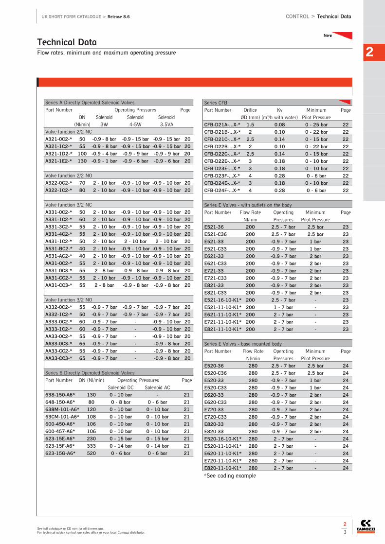
Flow rates, minimum and maximum operating pressure
Technical Data2
See full catalogue or CD rom for all dimensions.For technical advice contact our sales office or your local Camozzi distributor.
UK SHORT FORM CATALOGUE > Release 8.6 CONTROL > Technical Data
2
3
*See coding example
Series A Directly Operated Solenoid Valves
Part Number Operating Pressures Page
QN Solenoid Solenoid Solenoid
(Nl/min) 3W 4-5W 3.5VA
Valve function 2/2 NC
A321-0C2-* 50 -0.9 - 8 bar -0.9 - 15 bar -0.9 - 15 bar 20
A321-1C2-* 55 -0.9 - 8 bar -0.9 - 15 bar -0.9 - 15 bar 20
A321-1D2-* 100 -0.9 - 4 bar -0.9 - 9 bar -0.9 - 9 bar 20
A321-1E2-* 130 -0.9 - 1 bar -0.9 - 6 bar -0.9 - 6 bar 20
Valve function 2/2 NO
A322-0C2-* 70 2 - 10 bar -0.9 - 10 bar -0.9 - 10 bar 20
A322-1C2-* 80 2 - 10 bar -0.9 - 10 bar -0.9 - 10 bar 20
Valve function 3/2 NC
A331-0C2-* 50 2 - 10 bar -0.9 - 10 bar -0.9 - 10 bar 20
A331-1C2-* 60 2 - 10 bar -0.9 - 10 bar -0.9 - 10 bar 20
A331-3C2-* 55 2 - 10 bar -0.9 - 10 bar -0.9 - 10 bar 20
A331-4C2-* 55 2 - 10 bar -0.9 - 10 bar -0.9 - 10 bar 20
A431-1C2-* 50 2 - 10 bar 2 - 10 bar 2 - 10 bar 20
A531-BC2-* 40 2 - 10 bar -0.9 - 10 bar -0.9 - 10 bar 20
A631-AC2-* 40 2 - 10 bar -0.9 - 10 bar -0.9 - 10 bar 20
AA31-0C2-* 55 2 - 10 bar -0.9 - 10 bar -0.9 - 10 bar 20
AA31-0C3-* 55 2 - 8 bar -0.9 - 8 bar -0.9 - 8 bar 20
AA31-CC2-* 55 2 - 10 bar -0.9 - 10 bar -0.9 - 10 bar 20
AA31-CC3-* 55 2 - 8 bar -0.9 - 8 bar -0.9 - 8 bar 20
Valve function 3/2 NO
A332-0C2-* 55 -0.9 - 7 bar -0.9 - 7 bar -0.9 - 7 bar 20
A332-1C2-* 50 -0.9 - 7 bar -0.9 - 7 bar -0.9 - 7 bar 20
A333-0C2-* 60 -0.9 - 7 bar - -0.9 - 10 bar 20
A333-1C2-* 60 -0.9 - 7 bar - -0.9 - 10 bar 20
AA33-0C2-* 55 -0.9 - 7 bar - -0.9 - 10 bar 20
AA33-0C3-* 65 -0.9 - 7 bar - -0.9 - 8 bar 20
AA33-CC2-* 55 -0.9 - 7 bar - -0.9 - 8 bar 20
AA33-CC3-* 65 -0.9 - 7 bar - -0.9 - 8 bar 20
Series 6 Directly Operated Solenoid Valves
Part Number QN (Nl/min) Operating Pressures Page
Solenoid DC Solenoid AC
638-150-A6* 130 0 - 10 bar - 21
648-150-A6* 80 0 - 8 bar 0 - 6 bar 21
638M-101-A6* 120 0 - 10 bar 0 - 10 bar 21
63CM-101-A6* 108 0 - 10 bar 0 - 10 bar 21
600-450-A6* 106 0 - 10 bar 0 - 10 bar 21
600-457-A6* 106 0 - 10 bar 0 - 10 bar 21
623-15E-A6* 230 0 - 15 bar 0 - 15 bar 21
623-15F-A6* 333 0 - 14 bar 0 - 14 bar 21
623-15G-A6* 520 0 - 6 bar 0 - 6 bar 21
Series CFB
Part Number Orifice Kv Minimum Page
ØD (mm) (m3/h with water) Pilot Pressure
CFB-D21A-...X-* 1.5 0.08 0 - 25 bar 22
CFB-D21B-...X-* 2 0.10 0 - 22 bar 22
CFB-D21C-...X-* 2.5 0.14 0 - 15 bar 22
CFB-D22B-...X-* 2 0.10 0 - 22 bar 22
CFB-D22C-...X-* 2.5 0.14 0 - 15 bar 22
CFB-D22E-...X-* 3 0.18 0 - 10 bar 22
CFB-D23E-...X-* 3 0.18 0 - 10 bar 22
CFB-D23F-...X-* 4 0.28 0 - 6 bar 22
CFB-D24E-...X-* 3 0.18 0 - 10 bar 22
CFB-D24F-...X-* 4 0.28 0 - 6 bar 22
Series E Valves - with outlets on the body
Part Number Flow Rate Operating Minimum Page
Nl/min Pressures Pilot Pressure
E521-36 200 2.5 - 7 bar 2.5 bar 23
E521-C36 200 2.5 - 7 bar 2.5 bar 23
E521-33 200 -0.9 - 7 bar 1 bar 23
E521-C33 200 -0.9 - 7 bar 1 bar 23
E621-33 200 -0.9 - 7 bar 2 bar 23
E621-C33 200 -0.9 - 7 bar 2 bar 23
E721-33 200 -0.9 - 7 bar 2 bar 23
E721-C33 200 -0.9 - 7 bar 2 bar 23
E821-33 200 -0.9 - 7 bar 2 bar 23
E821-C33 200 -0.9 - 7 bar 2 bar 23
E521-16-10-K1* 200 2.5 - 7 bar - 23
E521-11-10-K1* 200 1 - 7 bar - 23
E621-11-10-K1* 200 2 - 7 bar - 23
E721-11-10-K1* 200 2 - 7 bar - 23
E821-11-10-K1* 200 2 - 7 bar - 23
Series E Valves - base mounted body
Part Number Flow Rate Operating Minimum Page
Nl/min Pressures Pilot Pressure
E520-36 280 2.5 - 7 bar 2.5 bar 24
E520-C36 280 2.5 - 7 bar 2.5 bar 24
E520-33 280 -0.9 - 7 bar 1 bar 24
E520-C33 280 -0.9 - 7 bar 1 bar 24
E620-33 280 -0.9 - 7 bar 2 bar 24
E620-C33 280 -0.9 - 7 bar 2 bar 24
E720-33 280 -0.9 - 7 bar 2 bar 24
E720-C33 280 -0.9 - 7 bar 2 bar 24
E820-33 280 -0.9 - 7 bar 2 bar 24
E820-33 280 -0.9 - 7 bar 2 bar 24
E520-16-10-K1* 280 2 - 7 bar - 24
E520-11-10-K1* 280 2 - 7 bar - 24
E620-11-10-K1* 280 2 - 7 bar - 24
E720-11-10-K1* 280 2 - 7 bar - 24
E820-11-10-K1* 280 2 - 7 bar - 24
New

Flow rates, minimum and maximum operating pressure
Technical Data
CONTR
OL
2
The company reserves the right to vary models and dimensions without notice.Products designed for industrial applications. General terms and conditions for sale are available on www.camozzi.co.uk
CONTROL > Technical Data UK SHORT FORM CATALOGUE > Release 8.6
2
4
Series EN Solenoid Valves
Part Number Flow Rate Operating Minimum Page
Nl/min Pressures Pilot Pressure
EN731-E11-P* 550 -0.9 - 10 bar 3 29
EN751-E11-P* 920 -0.9 - 10 bar 3 29
EN731-E11-W* 550 -0.9 - 10 bar 3 29
EN751-E11-W* 920 -0.9 - 10 bar 3 29
EN831-E11-P* 550 -0.9 - 10 bar 3 29
EN851-E11-P* 920 -0.9 - 10 bar 3 29
EN831-E11-W* 550 -0.9 - 10 bar 3 29
EN851-E11-W* 920 -0.9 - 10 bar 3 29
EN631-11-PN* 550 3 - 10 bar - 29
EN651-11-PN* 920 3 - 10 bar - 29
EN731-E11-PN* 550 -0.9 - 10 bar 3 29
EN751-11-PN* 920 3 - 10 bar - 29
EN831-11-PN* 550 3 - 10 bar - 29
EN851-11-PN* 920 3 - 10 bar - 29
EN631-E11-PN* 550 -0.9 - 10 bar 3 29
EN651-E11-PN* 920 -0.9 - 10 bar 3 29
EN731-E11-PN* 550 -0.9 - 10 bar 3 29
EN751-E11-PN* 920 -0.9 - 10 bar 3 29
EN831-E11-PN* 550 -0.9 - 10 bar 3 29
EN851-E11-PN* 920 -0.9 - 10 bar 3 29
EN530-36 610 2.5 - 10 bar 2.5 30
EN550-36 1000 2 - 10 bar 2.5 30
EN530-33 610 -0.9 - 10 bar 2 30
EN550-33 1000 -0.9 - 10 bar 2 30
EN630-33 610 -0.9 - 10 bar 3 30
EN650-33 1000 -0.9 - 10 bar 3 30
EN730-33 610 -0.9 - 10 bar 3 30
EN750-33 1000 -0.9 - 10 bar 3 30
EN830-33 610 -0.9 - 10 bar 3 30
EN850-33 1000 -0.9 - 10 bar 3 30
EN530-16-P* 610 2.5 - 10 bar - 30
EN550-16-P* 1000 2.5 - 10 bar - 30
EN530-16-W* 610 2.5 - 10 bar - 30
EN550-16-W* 1000 2.5 - 10 bar - 30
EN530-E16-P* 610 -0.9 - 10 bar 2.5 30
EN550-E16-P* 1000 -0.9 - 10 bar 2 30
EN530-E16-W* 610 -0.9 - 10 bar 2.5 30
EN550-E16-W* 1000 -0.9 - 10 bar 2 30
EN530-11-P* 610 2 - 10 bar - 30
EN550-11-P* 1000 2 - 10 bar - 30
EN530-11-W* 610 2 - 10 bar - 30
EN550-11-W* 1000 2 - 10 bar - 30
EN530-E11-P* 610 -0.9 - 10 bar 2 30
EN550-E11-P* 1000 -0.9 - 10 bar 2 30
EN530-E11-W* 610 -0.9 - 10 bar 2 30
EN550-E11-W* 1000 -0.9 - 10 bar 2 30
EN530-16-PN* 610 2.5 - 10 bar - 30
EN550-16-PN* 1000 2.5 - 10 bar - 30
EN530-E16-PN* 610 -0.9 - 10 bar 2.5 30
EN550-E16-PN* 1000 -0.9 - 10 bar 2.5 30
*See coding example
Series EN Solenoid Valves
Part Number Flow Rate Operating Minimum Page
Nl/min Pressures Pilot Pressure
EN531-36 550 -0.9 - 10 bar 2.5 28
EN551-36 920 -0.9 - 10 bar 2.5 28
EN531-33 550 -0.9 - 10 bar 2 28
EN551-33 920 -0.9 - 10 bar 2 28
EN631-33 550 -0.9 - 10 bar 3 28
EN651-33 920 -0.9 - 10 bar 3 28
EN731-33 550 -0.9 - 10 bar 3 28
EN751-33 920 -0.9 - 10 bar 3 28
EN831-33 550 -0.9 - 10 bar 3 28
EN851-33 920 -0.9 - 10 bar 3 28
EN531-16-P* 550 2.5 - 10 bar - 28
EN551-16-P* 920 2.5 - 10 bar - 28
EN531-16-W* 550 2.5 - 10 bar - 28
EN551-16-W* 920 2.5 - 10 bar - 28
EN531-E16-P* 550 -0.9 - 10 bar 2.5 28
EN551-E16-P* 920 -0.9 - 10 bar 2.5 28
EN531-E16-W* 550 -0.9 - 10 bar 2.5 28
EN551-E16-W* 920 -0.9 - 10 bar 2.5 28
EN531-11-P* 550 2 - 10 bar - 28
EN551-11-P* 920 2 - 10 bar - 28
EN531-11-W* 550 2 - 10 bar - 28
EN551-11-W* 920 2 - 10 bar - 28
EN531-E11-P* 550 -0.9 - 10 bar 2 28
EN551-E11-P* 920 -0.9 - 10 bar 2 28
EN531-E11-W* 550 -0.9 - 10 bar 2 28
EN551-E11-W* 920 -0.9 - 10 bar 2 28
EN531-16-PN* 550 2.5 - 10 bar - 28
EN551-16-PN* 920 2.5 - 10 bar - 28
EN531-E16-PN* 550 -0.9 - 10 bar 2.5 28
EN551-E16-PN* 920 -0.9 - 10 bar 2.5 28
EN531-11-PN* 550 2 - 10 bar - 28
EN551-11-PN* 920 2 - 10 bar - 28
EN531-E11-PN* 550 -0.9 - 10 bar 2 28
EN551-E11-PN* 920 -0.9 - 10 bar 2 28
EN631-11-P* 550 3 - 10 bar - 29
EN651-11-P* 920 3 - 10 bar - 29
EN631-11-W* 550 3 - 10 bar - 29
EN651-11-W* 920 3 - 10 bar - 29
EN731-11-P* 550 3 - 10 bar - 29
EN751-11-P* 920 3 - 10 bar - 29
EN731-11-W* 550 3 - 10 bar - 29
EN751-11-W* 920 3 - 10 bar - 29
EN831-11-P* 550 3 - 10 bar - 29
EN851-11-P* 920 3 - 10 bar - 29
EN831-11-W* 550 3 - 10 bar - 29
EN851-11-W* 920 3 - 10 bar - 29
EN631-E11-P* 550 -0.9 - 10 3 29
EN651-E11-P* 920 -0.9 - 10 3 29
EN631-E11-W* 550 -0.9 - 10 3 29
EN651-E11-W* 920 -0.9 - 10 3 29

Series EN Solenoid Valves
Part Number Flow Rate Operating Minimum Page
Nl/min Pressures Pilot Pressure
EN530-11-PN* 610 2 - 10 bar - 30
EN550-11-PN* 1000 2 - 10 bar - 30
EN530-E11-PN* 610 -0.9 - 10 bar 2 30
EN550-E11-PN* 1000 -0.9 - 10 bar 3 30
EN630-11-P* 610 3 - 10 bar - 31
EN650-11-P* 1000 3 - 10 bar - 31
EN630-11-W* 610 3 - 10 bar - 31
EN650-11-W* 1000 3 - 10 bar - 31
EN730-11-P* 610 3 - 10 bar - 31
EN750-11-P* 1000 3 - 10 bar - 31
EN730-11-W* 610 3 - 10 bar - 31
EN750-11-W* 1000 3 - 10 bar - 31
EN830-11-P* 610 3 - 10 bar - 31
EN850-11-P* 1000 3 - 10 bar - 31
EN830-11-W* 610 3 - 10 bar - 31
EN850-11-W* 1000 3 - 10 bar - 31
EN630-E11-P* 610 -0.9 - 10 bar 3 31
EN650-E11-P* 1000 -0.9 - 10 bar 3 31
EN630-E11-W* 610 -0.9 - 10 bar 3 31
EN650-E11-W* 1000 -0.9 - 10 bar 3 31
EN730-E11-P* 610 -0.9 - 10 bar 3 31
EN750-E11-P* 1000 -0.9 - 10 bar 3 31
EN730-E11-W* 610 -0.9 - 10 bar 3 31
EN750-E11-W* 1000 -0.9 - 10 bar 3 31
EN830-E11-P* 610 -0.9 - 10 bar 3 31
EN850-E11-P* 1000 -0.9 - 10 bar 3 31
EN830-E11-W* 610 -0.9 - 10 bar 3 31
EN850-E11-W* 1000 -0.9 - 10 bar 3 31
EN630-11-PN* 610 3 - 10 bar - 31
EN650-11-PN* 1000 3 - 10 bar - 31
EN730-11-PN* 610 3 - 10 bar - 31
EN750-11-PN* 1000 3 - 10 bar - 31
EN830-11-PN* 610 3 - 10 bar - 31
EN850-11-PN* 1000 3 - 10 bar - 31
EN630-E11-PN* 610 -0.9 - 10 bar 3 31
EN650-E11-PN* 1000 -0.9 - 10 bar 3 31
EN730-E11-PN* 610 -0.9 - 10 bar 3 31
EN750-E11-PN* 1000 -0.9 - 10 bar 3 31
EN830-E11-PN* 610 -0.9 - 10 bar 3 31
EN850-E11-PN* 1000 -0.9 - 10 bar 3 31
Flow rates, minimum and maximum operating pressure
Technical Data2
See full catalogue or CD rom for all dimensions.For technical advice contact our sales office or your local Camozzi distributor.
UK SHORT FORM CATALOGUE > Release 8.6 CONTROL > Technical Data
2
5
*See voltage coding
Series 3 and 4 Electropneumatically Operated Valves
Part Number Flow Rate Operating Minimum Page
Nl/min Pressures Pilot Pressure
338-015-02-* 700 2.5 - 10 bar - 33
338L-015-02-* 700 2.5 - 10 bar - 33
348-015-02-* 700 2.5 - 10 bar - 33
348L-015-02-* 700 2.5 - 10 bar - 33
338-011-02-* 700 1.5 - 10 bar - 33
338L-011-02-* 700 1.5 - 10 bar - 33
338D-015-02-* 700 2.5 - 10 bar - 33
348D-015-02-* 700 2.5 - 10 bar - 33
338D-E15-02-* 700 -0.9 - 10 bar 2.5 bar 33
348D-E15-02-* 700 -0.9 - 10 bar 2.5 bar 33
398D-015-02-* 700 2.5 - 10 bar - 33
398D-E15-02-* 700 -0.9 - 10 bar 2.5 bar 33
358-015-02-* 700 2.5 - 10 bar - 33
358-E15-02-* 700 -0.9 - 10 bar 2.5 bar 33
358-016-02-* 700 2.5 - 10 bar - 33
358-011-02-* 700 1.5 - 10 bar - 33
358-E11-02-* 700 -0.9 - 10 bar 1.5 - 10 bar 33
Series 3 and 4 Electropneumatically Operated Valves
Part Number Flow Rate Operating Pilot Pressure Page
Nl/min Pressures
368-011-02-* 700 2 - 10 bar - 34
368-E11-02-* 700 -0.9 - 10 bar 2 - 10 bar 34
378-011-02-* 700 2 - 10 bar - 34
378-E11-02-* 700 -0.9 - 10 bar 2 - 10 bar 34
388-011-02-* 700 2 - 10 bar - 34
388-E11-02-* 700 -0.9 - 10 bar 2 - 10 bar 34
334-015-02-* 1300 2.5 - 10 bar - 34
334-E15-02-* 1300 -0.9 - 10 bar 2.5 - 10 bar 34
344-015-02-* 1300 2.5 - 10 bar - 34
344-E15-02-* 1300 -0.9 - 10 bar 2.5 - 10 bar 34
334-011-02-* 1300 2.5 - 10 bar - 34
334-E11-02-* 1300 -0.9 - 10 bar 2.5 - 10 bar 34
334D-015-02-* 1200 2.5 - 10 bar - 35
334D-E15-02-* 1200 -0.9 - 10 bar 2.5 - 10 bar 35
344D-015-02-* 1050 2.5 - 10 bar - 35
344D-E15-02-* 1050 -0.9 - 10 bar 2.5 - 10 bar 35
394D-015-02-* 1050 2 - 10 bar - 35
394D-E15-02-* 1050 -0.9 - 10 bar 2.5 - 10 bar 35
354-015-02-* 1300 2.5 - 10 bar - 35
354-E15-02-* 1300 -0.9 - 10 bar 2.5 - 10 bar 35
354-011-02-* 1300 2.5 - 10 bar - 35
354-E11-02-* 1300 -0.9 - 10 bar 2.5 - 10 bar 35
364-011-02-* 1200 2.5 - 10 bar - 36
364-E11-02-* 1200 -0.9 - 10 bar 2.5 - 10 bar 36
374-011-02-* 1200 2.5 - 10 bar - 36
374-E11-02-* 1200 -0.9 - 10 bar 2.5 - 10 bar 36
384-011-02-* 1200 2.5 - 10 bar - 36
384-E11-02-* 1200 -0.9 - 10 bar 2.5 - 10 bar 36
438-015-22-* 650 2.5 - 10 bar - 36
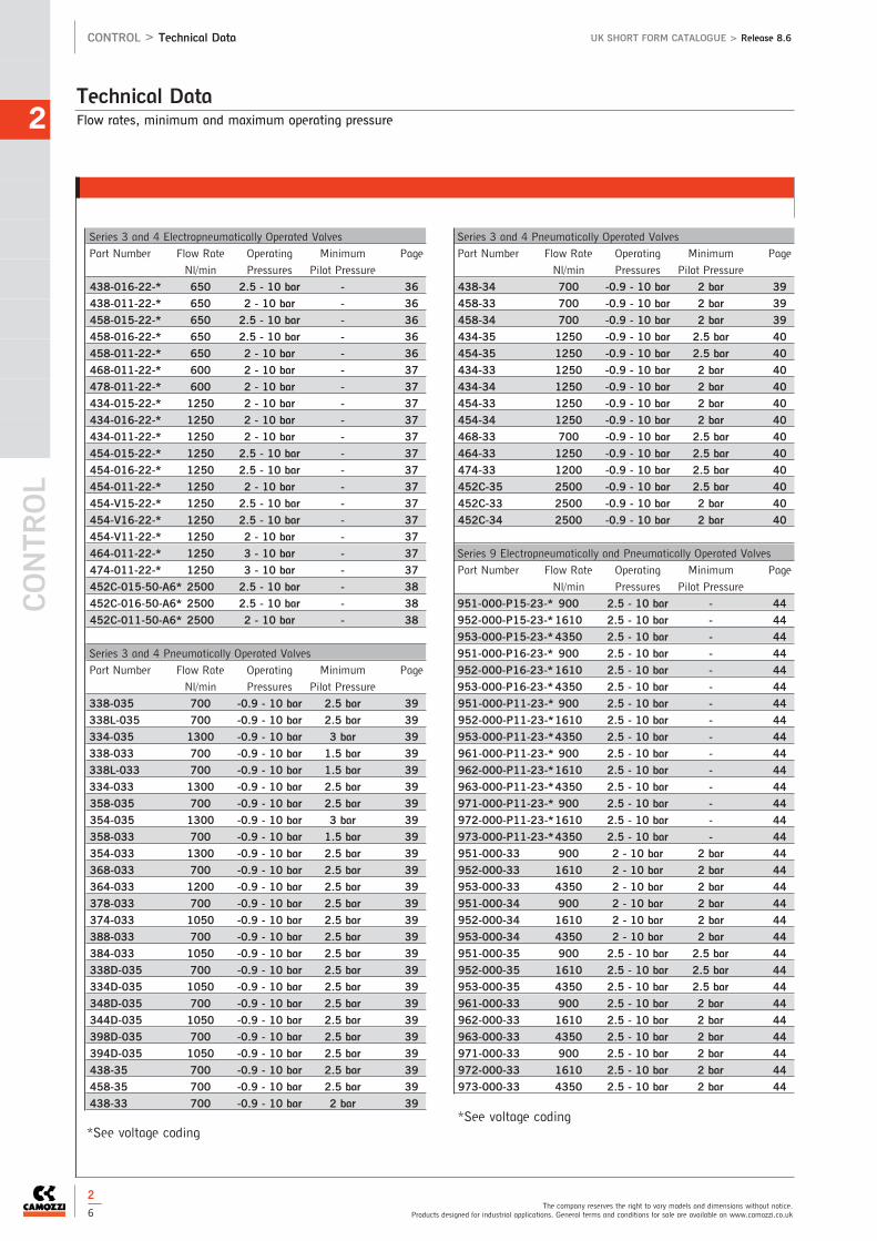
Flow rates, minimum and maximum operating pressure
Technical Data
CONTR
OL
2
The company reserves the right to vary models and dimensions without notice.Products designed for industrial applications. General terms and conditions for sale are available on www.camozzi.co.uk
CONTROL > Technical Data UK SHORT FORM CATALOGUE > Release 8.6
2
6
Series 3 and 4 Electropneumatically Operated Valves
Part Number Flow Rate Operating Minimum Page
Nl/min Pressures Pilot Pressure
438-016-22-* 650 2.5 - 10 bar - 36
438-011-22-* 650 2 - 10 bar - 36
458-015-22-* 650 2.5 - 10 bar - 36
458-016-22-* 650 2.5 - 10 bar - 36
458-011-22-* 650 2 - 10 bar - 36
468-011-22-* 600 2 - 10 bar - 37
478-011-22-* 600 2 - 10 bar - 37
434-015-22-* 1250 2 - 10 bar - 37
434-016-22-* 1250 2 - 10 bar - 37
434-011-22-* 1250 2 - 10 bar - 37
454-015-22-* 1250 2.5 - 10 bar - 37
454-016-22-* 1250 2.5 - 10 bar - 37
454-011-22-* 1250 2 - 10 bar - 37
454-V15-22-* 1250 2.5 - 10 bar - 37
454-V16-22-* 1250 2.5 - 10 bar - 37
454-V11-22-* 1250 2 - 10 bar - 37
464-011-22-* 1250 3 - 10 bar - 37
474-011-22-* 1250 3 - 10 bar - 37
452C-015-50-A6* 2500 2.5 - 10 bar - 38
452C-016-50-A6* 2500 2.5 - 10 bar - 38
452C-011-50-A6* 2500 2 - 10 bar - 38
Series 3 and 4 Pneumatically Operated Valves
Part Number Flow Rate Operating Minimum Page
Nl/min Pressures Pilot Pressure
338-035 700 -0.9 - 10 bar 2.5 bar 39
338L-035 700 -0.9 - 10 bar 2.5 bar 39
334-035 1300 -0.9 - 10 bar 3 bar 39
338-033 700 -0.9 - 10 bar 1.5 bar 39
338L-033 700 -0.9 - 10 bar 1.5 bar 39
334-033 1300 -0.9 - 10 bar 2.5 bar 39
358-035 700 -0.9 - 10 bar 2.5 bar 39
354-035 1300 -0.9 - 10 bar 3 bar 39
358-033 700 -0.9 - 10 bar 1.5 bar 39
354-033 1300 -0.9 - 10 bar 2.5 bar 39
368-033 700 -0.9 - 10 bar 2.5 bar 39
364-033 1200 -0.9 - 10 bar 2.5 bar 39
378-033 700 -0.9 - 10 bar 2.5 bar 39
374-033 1050 -0.9 - 10 bar 2.5 bar 39
388-033 700 -0.9 - 10 bar 2.5 bar 39
384-033 1050 -0.9 - 10 bar 2.5 bar 39
338D-035 700 -0.9 - 10 bar 2.5 bar 39
334D-035 1050 -0.9 - 10 bar 2.5 bar 39
348D-035 700 -0.9 - 10 bar 2.5 bar 39
344D-035 1050 -0.9 - 10 bar 2.5 bar 39
398D-035 700 -0.9 - 10 bar 2.5 bar 39
394D-035 1050 -0.9 - 10 bar 2.5 bar 39
438-35 700 -0.9 - 10 bar 2.5 bar 39
458-35 700 -0.9 - 10 bar 2.5 bar 39
438-33 700 -0.9 - 10 bar 2 bar 39
Series 3 and 4 Pneumatically Operated Valves
Part Number Flow Rate Operating Minimum Page
Nl/min Pressures Pilot Pressure
438-34 700 -0.9 - 10 bar 2 bar 39
458-33 700 -0.9 - 10 bar 2 bar 39
458-34 700 -0.9 - 10 bar 2 bar 39
434-35 1250 -0.9 - 10 bar 2.5 bar 40
454-35 1250 -0.9 - 10 bar 2.5 bar 40
434-33 1250 -0.9 - 10 bar 2 bar 40
434-34 1250 -0.9 - 10 bar 2 bar 40
454-33 1250 -0.9 - 10 bar 2 bar 40
454-34 1250 -0.9 - 10 bar 2 bar 40
468-33 700 -0.9 - 10 bar 2.5 bar 40
464-33 1250 -0.9 - 10 bar 2.5 bar 40
474-33 1200 -0.9 - 10 bar 2.5 bar 40
452C-35 2500 -0.9 - 10 bar 2.5 bar 40
452C-33 2500 -0.9 - 10 bar 2 bar 40
452C-34 2500 -0.9 - 10 bar 2 bar 40
Series 9 Electropneumatically and Pneumatically Operated Valves
Part Number Flow Rate Operating Minimum Page
Nl/min Pressures Pilot Pressure
951-000-P15-23-* 900 2.5 - 10 bar - 44
952-000-P15-23-* 1610 2.5 - 10 bar - 44
953-000-P15-23-* 4350 2.5 - 10 bar - 44
951-000-P16-23-* 900 2.5 - 10 bar - 44
952-000-P16-23-* 1610 2.5 - 10 bar - 44
953-000-P16-23-* 4350 2.5 - 10 bar - 44
951-000-P11-23-* 900 2.5 - 10 bar - 44
952-000-P11-23-*1610 2.5 - 10 bar - 44
953-000-P11-23-*4350 2.5 - 10 bar - 44
961-000-P11-23-* 900 2.5 - 10 bar - 44
962-000-P11-23-*1610 2.5 - 10 bar - 44
963-000-P11-23-*4350 2.5 - 10 bar - 44
971-000-P11-23-* 900 2.5 - 10 bar - 44
972-000-P11-23-*1610 2.5 - 10 bar - 44
973-000-P11-23-*4350 2.5 - 10 bar - 44
951-000-33 900 2 - 10 bar 2 bar 44
952-000-33 1610 2 - 10 bar 2 bar 44
953-000-33 4350 2 - 10 bar 2 bar 44
951-000-34 900 2 - 10 bar 2 bar 44
952-000-34 1610 2 - 10 bar 2 bar 44
953-000-34 4350 2 - 10 bar 2 bar 44
951-000-35 900 2.5 - 10 bar 2.5 bar 44
952-000-35 1610 2.5 - 10 bar 2.5 bar 44
953-000-35 4350 2.5 - 10 bar 2.5 bar 44
961-000-33 900 2.5 - 10 bar 2 bar 44
962-000-33 1610 2.5 - 10 bar 2 bar 44
963-000-33 4350 2.5 - 10 bar 2 bar 44
971-000-33 900 2.5 - 10 bar 2 bar 44
972-000-33 1610 2.5 - 10 bar 2 bar 44
973-000-33 4350 2.5 - 10 bar 2 bar 44
*See voltage coding*See voltage coding

Flow rates, minimum and maximum operating pressure
Technical Data2
See full catalogue or CD rom for all dimensions.For technical advice contact our sales office or your local Camozzi distributor.
UK SHORT FORM CATALOGUE > Release 8.6 CONTROL > Technical Data
2
7
Series NA NAMUR Valves
Part Number Flow Rate Operating Minimum Page
Nl/min Pressures Pilot Pressure
NA54N-15-02-* 1000 2 - 10 bar - 46
NA34N-15-02-* 1000 2 - 10 bar - 46
NA44N-15-02-* 1000 2 - 10 bar - 46
NA54N-11-02-* 1000 1 - 10 bar - 46
NA34N-11-02-* 1000 1 - 10 bar - 46
NA54N-33 1000 -0.9 - 10 bar 2.5 bar 46
NA64N-33 1000 -0.9 - 10 bar 2.5 bar 46
NA74N-33 1000 -0.9 - 10 bar 2.5 bar 46
NA84N-33 1000 -0.9 - 10 bar 2.5 bar 46
NA54N-35 1000 -0.9 - 10 bar 2.5 bar 46
NA64N-11-02-* 1000 1.5 - 10 bar - 46
NA74N-11-02-* 1000 1.5 - 10 bar - 46
NA84N-11-02-* 1000 1.5 - 10 bar - 46
Series 3 Valve Island
See individual valve codes Section 2/5 for flow rate and operating
pressures
Series Y Valve Island
Part Number Flow Rate Operating Pilot Page
Nl/min Pressures Pressure
All Series Y 800 -0.9 - 10 bar 3 - 7 bar 61
Series H Valve Island
Part Number Flow Rate Operating Pilot Page
Nl/min Pressures Pressure
Series H 10.5mm 400 -0.9 - 10 bar 3 - 7 bar 65
Series H 21mm 700 -0.9 - 10 bar 3 - 7 bar 65
Series F Valve Island
Part Number Flow Rate Operating Pilot Page
Nl/min Pressures Pressure
Series F 12mm 250 -0.9 - 10 bar 3 - 7 bar 69
Series F 14mm 500 -0.9 - 10 bar 3 - 7 bar 69
*Actuating Force at 6 bar
Series 2 Mechanically Operated Minivalves
Part Number Flow Rate Operating Actuating Page
Nl/min Pressures Force*
235-945 60 2 - 8 bar 6 N 76
234-945 60 2 - 8 bar 6 N 76
245-945 60 2 - 8 bar 6 N 76
244-945 60 2 - 8 bar 6 N 76
235-985 60 2 - 8 bar 6 N 76
234-985 60 2 - 8 bar 6 N 76
245-985 60 2 - 8 bar 6 N 76
244-985 60 2 - 8 bar 6 N 76
235-955 60 2 - 8 bar 4 N 76
234-955 60 2 - 8 bar 4 N 76
245-955 60 2 - 8 bar 4 N 76
244-955 60 2 - 8 bar 4 N 76
235-965 60 2 - 8 bar 6 N 76
234-965 60 2 - 8 bar 6 N 76
245-965 60 2 - 8 bar 6 N 76
244-965 60 2 - 8 bar 6 N 76
Series 1 and 3 Mechanically Operated Valves
Part Number Flow Rate Operating Actuating Page
Nl/min Pressures Force*
338-945 700 -0.9 - 10 bar 32 N 76
358-945 700 -0.9 - 10 bar 35 N 76
338-955 700 -0.9 - 10 bar 15 N 76
358-955 700 -0.9 - 10 bar 17 N 76
338-965 700 -0.9 - 10 bar 15 N 77
358-965 700 -0.9 - 10 bar 16 N 77
138-945 500 0 - 10 bar 70 N 77
148-945 500 0 - 10 bar 70 N 77
158-945 500 0 - 10 bar 120 N 77
138-955 500 0 - 10 bar 36 N 77
158-955 500 0 - 10 bar 92 N 77
138-965 500 0 - 10 bar 41 N 77
134-945 1250 0 - 10 bar 64 N 77
154-945 1250 0 - 10 bar 147 N 77
134-955 1250 0 - 10 bar 41 N 77
154-955 1250 0 - 10 bar 110 N 77
*Actuating Force at 6 bar
New

CONTR
OL
2
The company reserves the right to vary models and dimensions without notice.Products designed for industrial applications. General terms and conditions for sale are available on www.camozzi.co.uk
CONTROL > Technical Data UK SHORT FORM CATALOGUE > Release 8.6
2
8
Flow rates, minimum and maximum operating pressure
Technical Data
Series 1, 3, 4 and VMS Manually Operated Valves
Part Number Flow Rate Operating Actuating Page
Nl/min Pressures Force*
338-990 700 -0.9 - 10 bar 18 N 82
358-990 700 -0.9 - 10 bar 18 N 82
338-895 700 -0.9 - 10 bar 35 N 82
338-896 700 -0.9 - 10 bar 35 N 82
338-897 700 -0.9 - 10 bar 35 N 82
358-895 700 -0.9 - 10 bar 35 N 82
358-896 700 -0.9 - 10 bar 35 N 82
358-897 700 -0.9 - 10 bar 35 N 82
338-975 700 -0.9 - 10 bar 35 N 82
338-976 700 -0.9 - 10 bar 35 N 82
338-977 700 -0.9 - 10 bar 35 N 82
358-975 700 -0.9 - 10 bar 35 N 82
358-976 700 -0.9 - 10 bar 35 N 82
358-977 700 -0.9 - 10 bar 35 N 82
338-910 700 -0.9 - 10 bar 6 N 82
338-915 700 -0.9 - 10 bar 35 N 82
358-910 700 -0.9 - 10 bar 6 N 82
358-915 700 -0.9 - 10 bar 35 N 82
338-900 700 -0.9 - 10 bar 6 N 82
338-905 700 -0.9 - 10 bar 35 N 82
358-900 700 -0.9 - 10 bar 5 N 82
358-905 700 -0.9 - 10 bar 22 N 82
368-900 500 -0.9 - 10 bar 5 N 82
368-905 500 -0.9 - 10 bar 20 N 82
378-900 500 -0.9 - 10 bar 5 N 82
378-905 500 -0.9 - 10 bar 20 N 82
434-910 1250 -0.9 - 10 bar 10 N 83
434-915 1250 -0.9 - 10 bar 37 N 83
454-910 1250 -0.9 - 10 bar 10 N 83
454-915 1250 -0.9 - 10 bar 37 N 83
434-900 1250 -0.9 - 10 bar 5 N 83
434-905 1250 -0.9 - 10 bar 37 N 83
454-900 1250 -0.9 - 10 bar 5 N 83
454-905 1250 -0.9 - 10 bar 37 N 83
464-900 1250 -0.9 - 10 bar 5 N 83
464-905 1250 -0.9 - 10 bar 10 N 83
474-900 1250 -0.9 - 10 bar 5 N 83
474-905 1250 -0.9 - 10 bar 10 N 83
138-900 500 0 - 10 bar 25 N 83
134-900 1250 0 - 10 bar 30 N 83
158-900 500 0 - 10 bar 45 N 83
154-900 1250 0 - 10 bar 55 N 83
138-935 500 0 - 10 bar 38 N 83
134-935 1250 0 - 10 bar 40 N 83
Series 1, 3, 4 and VMS Manually Operated Valves
Part Number Flow Rate Flow Rate Operating Page
Nl/min P-A Nl/min A-R Pressures
VMS-105-M5 140 145 0 - 8 bar 83
VMS-118-1/8 600 740 0 - 8 bar 83
VMS-114-1/4 1200 1780 0 - 8 bar 83
VMS-138-3/8 2100 1830 0 - 8 bar 83
VMS-112-1/2 3350 4030 0 - 8 bar 83
VMS-134-3/4 5350 5000 0 - 8 bar 83
*Actuating Force at 6 bar
Series 3 and 4 Mechanically Operated Sensor Valves
Part Number Flow Rate Operating Actuating Page
Nl/min Pressures Force*
338-D15-9A5 700 4 - 10 bar 2 N 78
348-D15-9A5 700 4 - 10 bar 2 N 78
358-D15-9A5 700 4 - 10 bar 2 N 78
458-015-194 650 2.5 - 8 bar 6 N 78
458-011-294 650 2 - 8 bar 6 N 78
454-015-194 1250 2.5 - 8 bar 6 N 78
454-011-294 1250 2 - 8 bar 6 N 78
458-015-195 650 2.5 - 8 bar 4 N 78
458-011-295 650 2 - 8 bar 4 N 79
454-015-195 1250 2.5 - 8 bar 4 N 79
454-011-295 1250 2 - 8 bar 4 N 79
Series 2 and 3 Pneumatic and Electrical - Foot Operated Pedal
Part Number Flow Rate Operating Actuating Page
Nl/min Pressures Force*
354N-925 650 2.5 - 8 bar 17 N 79
3E2-925 - - - 79
235-925 60 2 - 8 bar - 79
234-925 60 2 - 8 bar - 79
Series 2 Manually Operated Console Minivalves
Part Number Flow Rate Operating Actuating Page
Nl/min Pressures Force*
235-895 60 2 - 8 bar 7 N 80
234-895 60 2 - 8 bar 7 N 80
235-975 60 2 - 8 bar 7 N 80
234-975 60 2 - 8 bar 7 N 80
235-972 60 2 - 8 bar 7 N 80
234-972 60 2 - 8 bar 7 N 80
235-905 60 2 - 8 bar - 80
234-905 60 2 - 8 bar - 80
235-990 60 2 - 8 bar - 81
234-990 60 2 - 8 bar - 81
285-870 60 2 - 8 bar - 81
284-870 60 2 - 8 bar - 81
235-904 60 2 - 8 bar - 81
234-904 60 2 - 8 bar - 81
235-000 60 2 - 8 bar - 81
234-000 60 2 - 8 bar - 81
245-000 60 2 - 8 bar - 81
244-000 60 2 - 8 bar - 81
285-000 60 2 - 8 bar - 81
284-000 60 2 - 8 bar - 81
234-9054 60 2 - 8 bar - 81
*Actuating Force at 6 bar

2
See full catalogue or CD rom for all dimensions.For technical advice contact our sales office or your local Camozzi distributor.
UK SHORT FORM CATALOGUE > Release 8.6 CONTROL > Technical Data
2
9
Flow rates, minimum and maximum operating pressure
Technical Data
Series 2L Basic Logic Valves
Part Number Flow Rate Nl/min Operating Page
(6 bar rP 1 bar) Pressures
All Logic Valves 70 2 - 8 bar 85
Series SCS, VNR, VSC and VSO Automatic Valves
Part Number Flow Rate Operating Min. Actuation Page
Nl/min Pressures Pressure
SCS-668-06 800 0.2 - 10 bar 0.2 bar 86
VNR-205-M5 50 1 - 10 bar 1 bar 86
VNR-210-1/8 600 0.2 - 10 bar 0.2 bar 86
VNR-843-07 1400 0.2 - 10 bar 0.2 bar 86
VNR-238-3/8 3000 0.02 - 10 bar 0.02 bar 86
VNR-212-1/2 5800 0.02 - 10 bar 0.02 bar 86
VNR-234-3/4 8000 0.06 - 10 bar 0.06 bar 86
VSO-425-M5 50 100 1 bar 86
VSO-426-04 50 100 1 bar 86
VSC-588-1/8 650 1000 0.5 bar 86
VSC-544-1/4 1100 2300 0.3 bar 86
VSC-522-1/2 4500 6700 0.2 bar 86
Series K8P Electronic Proportional Micro Regulator
Part Number Operating Page
Pressures
K8P-0-D5*2-0 0 - 10 bar 102
K8P-0-E5*2-0 0 - 3 bar 102
K8P-L-E5*2-0 0 - 3 bar 102
K8P-L-D5*2-0 0 - 10 bar 102
K8P-S-D5*2-0 0 - 10 bar 102
K8P-S-E5*2-0 0 - 3 bar 102
K8P-T-D5*2-0 0 - 10 bar 102
K8P-T-E5*2-0 0 - 3 bar 102
Series AP
Part Number Max Pressures Kv Page
(bar) (l/min)
Size 16mm
AP-6210-DR2-GP* 10 bar 0.4 104
AP-6210-FR2-GP* 8 bar 0.5 104
AP-6210-HR2-GP* 6 bar 0.65 104
AP-6210-LR2-GP* 4 bar 1.2 104
Size 22mm
AP-7211-FR2-U7* 10 bar 0.5 104
AP-7211-HR2-U7* 8 bar 0.65 104
AP-7211-LR2-U7* 6 bar 1.0 104
AP-7211-NR2-U7* 5 bar 1.6 104
AP-7211-QR2-U7* 4 bar 2.0 104
Size 16mm - body in PVDF
AP-6210-DR2-GP* 10 bar 0.4 104
AP-6210-FR2-GP* 8 bar 0.5 104
AP-6210-HR2-GP* 6 bar 0.65 104
AP-6210-LR2-GP* 4 bar 1.2 104For Technical Data on Flow Control Valves see full Camozzi
Catalogue or contact our sales office for further details.
New

2
See full catalogue or CD rom for all dimensions.For technical advice contact our sales office or your local Camozzi distributor.
UK SHORT FORM CATALOGUE > Release 8.6 CONTROL > Series K8
2
11
2/2 - 3/2 wayNormally Closed (NC) and Normally Open (NO)
Series K8 Directly Operated Mini-Solenoid Valves
CODING EXAMPLE
K8 0 00 - 3 0 3 - K 2 3
3
0
3
MATERIALS AND SEALS:0 = poppet, FKM seals
K8
0
00
SERIES: K8
BODY DESIGN:0 = single valve
MATERIALS:K = <None>
CONNECTION TYPE:2 = pin interface size 4mm
NO WAY - FUNCTIONS:0 = single base3 = 3 ways NC4 = 3 ways NO5 = 2 ways NC6 = 2 ways NO
NOMINAL DIAMETER:3 = 0.5
NO OF POSITIONS:00 = valve withoutseat
SOLENOID VOLTAGE:1 = 6V DC (0.6 W)2 = 12V DC (0.6 W)3 = 24V DC (0.6 W)
K
2
3
Technical DataType of ConstructionDirect acting poppet type
MediaFiltered air, class 5.4.4 according toISO 8573-1, inert gas
Operating PressureSee technical data page 2/2
Flow RateSee technical data page 2/2
KvSee technical data page 2/2
Operating Temperature0oC to +50oC
Protection ClassIP00
Response Time (ISO 12238)ON <10 msec - OFF <10 msec
MaterialsBody: Brass - stainless steel- PBTtechnopolymerSeals: FKM (EPDM on demand)Internal parts: stainless steel
InstallationIn any position
Special RequestsFor assistance, contact our technicaloffice or your local Camozzidistributor.
Part Number (2/2)
K8000-503-K23
K8000-603-K23
Part Number (3/2)
K8000-303-K23
K8000-403-K23
Part Number
120-803 with 300mm cable
120-806 with 600mm cable
Connector

CONTR
OL
2
CONTROL > Series K UK SHORT FORM CATALOGUE > Release 8.6
3/2 Way N.C. or N.O.Connection: M5.
The Camozzi range of Series K Directly Operated Solenoid Valves can work with dry or lubricated air.
Series K Directly Operated Mini-Solenoid Valves
Part Number Thread
K000-TP M5 Ports
Part Number Thread
K001-02 M5 Ports
Part Number Thread
K1*-02 M5 Ports
* = No of connections
90O Elec Connections In-line Elec Connections 300mm Twin Wire
Note: Supplied with gasket, fixing screws and an interface for N.O. valves to mount to single base or manifold
Excluder tap Single Sub-base
Part Number
121-803 with 300mm cable
121-806 with 600mm cable
121-810 with 1000mm cable
Part Number
K000-303-KB3
K000-303-KC3
K000-303-KD3
Part Number
K000-403-KB3
K000-403-KC3
K000-403-KD3
Part Number
K000-303-KF3
K000-303-KG3
K000-303-KH3
Part Number
K000-403-KF3
K000-403-KG3
K000-403-KH3
Part Number
K000-303-K13
K000-303-K23
K000-303-K33
Part Number
K000-403-K13
K000-403-K23
K000-403-K33
2
12
CODING EXAMPLE
K 0 00 - 3 0 3 - K 2 3
3
0
3
CONNECTIONS:0 = interface2 = M5 side outlets
NOMINAL DIAMETER:3 = 0.65
K
0
00
SERIES: K
BODY DESIGN:0 = single sub-base 1 = manifold
NO OF POSITIONS:00 = interface01 = single base (only M5)02-99 = manifold number of positions
SOLENOID VOLTAGE:* 1 = 6V DC* 2 = 12V DC* 3 = 24V DC
K
2
3
ENCAPSULATING MATERIAL:K = PBT body, HNBR poppetF= PBT body, FKM poppet
CONNECTION TYPE:1 = conn. 90° with protection and LED2 = conn. 90° with protection
* 3 = connection 90°* B = in-line conn. with protection and LED* C = in-line conn. with protection* D = in-line connection* F = cable (300mm) with protection and LED* G = cable (300mm) with protection* H = cable (300mm) only
Manifold Part No: K1**-02 Solenoid Connector
NO WAY - FUNCTIONS:0 = manifold or single base3 = 3 ways N.C.4 = 3 ways N.O.5 = 3 ways N.C. electric part
revolved by 180O6 = 3 ways N.O. electric part
revolved by 180O
The company reserves the right to vary models and dimensions without notice.Products designed for industrial applications. General terms and conditions for sale are available on www.camozzi.co.uk
EV04 EV04 EV04
EV06 EV06 EV06
Technical DataType of ConstructionDirect acting poppet type
MediaFiltered air, class 5.4.4 according toISO 8573-1, inert gas
Operating PressureSee technical data page 2/2
Flow RateSee technical data page 2/2
KvSee technical data page 2/2
Operating Temperature0oC to +50oC
MaterialsBody: PBT technopolymerSeals: NBR (FKM on demand)Internal parts: Stainless steel
Protection ClassIP50Special RequestsFor assistance, contact our technicaloffice or your local Camozzidistributor.
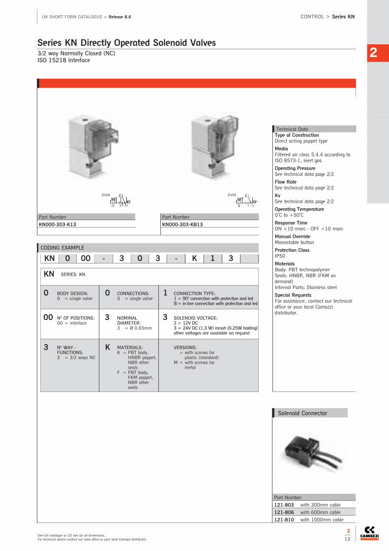
3/2 way Normally Closed (NC)ISO 15218 Interface
Series KN Directly Operated Solenoid Valves2
See full catalogue or CD rom for all dimensions.For technical advice contact our sales office or your local Camozzi distributor.
UK SHORT FORM CATALOGUE > Release 8.6
2
13
CONTROL > Series KN
Part Number
121-803 with 300mm cable
121-806 with 600mm cable
121-810 with 1000mm cable
Solenoid Connector
CODING EXAMPLE
KN 0 00 - 3 0 3 - K 1 3
KN
0
00
3
SERIES: KN
BODY DESIGN:0 = single valve
CONNECTION TYPE:1 = 90° connection with protection and ledB= in-line connection with protection and led
VERSIONS:= with screws forplastic (standard)
M = with screws formetal
NO OF POSITIONS:00 = interface
NO WAY -FUNCTIONS:3 = 3/2 ways NC
SOLENOID VOLTAGE:2 = 12V DC3 = 24V DC (1.3 W) inrush (0.25W holding) other voltages are available on request
Technical DataType of ConstructionDirect acting poppet type
MediaFiltered air class 5.4.4 according toISO 8573-1, inert gas
Operating PressureSee technical data page 2/2
Flow RateSee technical data page 2/2
KvSee technical data page 2/2
Operating Temperature0oC to +50oC
Response TimeON <10 msec - OFF <10 msec
Manual OverrideMonostable button
Protection ClassIP50
MaterialsBody: PBT technopolymer Seals: HNBR, NBR (FKM ondemand)Internal Parts: Stainless steel
Special RequestsFor assistance, contact our technicaloffice or your local Camozzidistributor.
EV04
Part Number
KN000-303-K13
EV04
Part Number
KN000-303-KB13
0
3
K
CONNECTIONS:0 = single valve
NOMINAL DIAMETER:3 = Ø 0.65mm
MATERIALS:K = PBT body,
HNBR poppet, NBR otherseals
F = PBT body,FKM poppet, NBR otherseals
1
3

CONTR
OL
2
The company reserves the right to vary models and dimensions without notice.Products designed for industrial applications. General terms and conditions for sale are available on www.camozzi.co.uk
CONTROL > Series KN High Flow UK SHORT FORM CATALOGUE > Release 8.6
2
14
3/2 way Normally Closed (NC)ISO 15218 Interface
Series KN High Flow Directly Operated Solenoid Valves
CODING EXAMPLE
KN 0 00 - 3 0 5 - F 1 8
0
5
F
CONNECTIONS:0 = single valve
KN
0
00
3
SERIES: KN
BODY DESIGN:0 = single valve
NOMINAL MAX DIAMETER: PRESSURE5 = Ø 1.1mm 7 bar6 = Ø 1.1mm 3 bar
MATERIALS:F = PBT body,
FKM poppet, NBR otherseals (FKMupon request)
NO OF POSITIONS:00 = interface
NO WAY -FUNCTIONS:3 = 3/2 ways NC
1
8
Technical DataType of ConstructionDirect acting poppet type
MediaFiltered air, class 5.4.4 according toISO 8573-1, inert gas
Operating PressureSee technical data page 2/2
Flow RateSee technical data page 2/2
KvSee technical data page 2/2
Operating Temperature0oC to +50oC
Response TimeON <10 msec - OFF <10 msec
Manual OverrideMonostable button
Protection ClassIP50
MaterialsBody: PBT technopolymer Seals: FKM, NBR (FKM on demand)Internal Parts: Stainless Steel
Special RequestsFor assistance, contact our technicaloffice or your local Camozzidistributor.
EV04 EV04
Part Number
KN000-305-F18
KN000-306-F18
Part Number
KN000-305-FB8
KN000-306-FB8
CONNECTION TYPE:1 = 90° connection withprotection and ledB= in-line connection withprotection and led
SOLENOID VOLTAGE:2 = 12V DC8 = 24V DC (4W) inrush
(1W holding)
FIXING:= with screws forplastic (standard)
M = with screws formetal
Part Number
121-803 with 300mm cable
121-806 with 600mm cable
121-810 with 1000mm cable
Solenoid Connector
New

2
See full catalogue or CD rom for all dimensions.For technical advice contact our sales office or your local Camozzi distributor.
UK SHORT FORM CATALOGUE > Release 8.6 CONTROL > Series W
2
15
3/2 Way N.C. or N.O.Connection: M5 (for single base), Ø3mm and Ø4mm cartridge (for manifolds). Electrical connection according to DIN 43650
The Camozzi range of Series W Directly Operated Mini-Solenoid Valves can work with dry or lubricated air.
Series W Directly Operated Mini-Solenoid Valves
Technical DataType of ConstructionDirect acting poppet type
MediaFiltered air, class 5.4.4 according toISO 8573-1, inert gas
Operating PressureSee technical data page 2/2
Flow RateSee technical data page 2/2
Kv0.22 to 0.54 (l/min)
Operating Temperature0oC to +50oC.
Response TimeON <10 msec - OFF <15 msec
Manual OverrideMonostable button
Protection ClassIP65 with connector
MaterialsBody: PBT technopolymerSeals: PU, NBR, (FKM on demand)Internal Parts: Stainless Steel
Special RequestsFor assistance, contact our technicaloffice or your local Camozzidistributor.
Part Number
W000-305-W23
W000-303-W23
W000-305-W24
W000-303-W24
Part Number
W000-405-W23
W000-403-W23
W000-405-W24
W000-403-W24
Part Number
W000-305-W13
W000-303-W13
Part Number
W000-405-W13
W000-403-W13
Note: For manifolds please refer to Series P valves see page 2/16Note: Supplied with gasket, fixing screws and an interface for N.O. valves to mount to single base or manifold
2 pin elec connections 2 wire elec connections
CODING EXAMPLE
W 0 00 - 3 0 3 - W 2 3
3
0
3
W
0
00
W
2
3
MATERIALS:W = technopolymer PBT body, FKMpoppet seal, other seals in NBR (FKMon demand)
CONNECTION TYPE:1= cables 300mm (only 24V DC)2 = 2 faston (24V - 48V DC)
SOLENOID VOLTAGE:2= 12V DC3= 24V DC4= 48V DC
NO WAY - FUNCTIONS:0 = manifold or single base3 = 3 ways N.C.4 = 3 ways N.O.5 = 3 ways N.C. electric part
revolved by 180O6 = 3 ways N.O. electric part
revolved by 180O
CONNECTIONS:0 = interfaceMANIFOLD CONNECTIONS (for series W, P and PN):2 = M5 side connection3 = Ø3 tube side connection4 = Ø4 tube side connection6 = M5 rear connection7 = Ø3 tube rear connection8 = Ø4 tube rear connection
NOMINAL DIAMETER:Nominal Diameter Max. Pressure1 = Ø0.8 (1W) 10 bar (NC) 24V only3 = Ø1.5 (2W) 7 bar (NC) 5 bar (NO)5 = Ø1.1 NC (2W) 10 bar (NC)
Ø0.9 NO (2W) 10 bar (NO)
SERIES: W
BODY DESIGN:0 = single sub-base (only M5)
or interface01 = single manifold02 = double manifold
NO OF POSITIONS:00 = interface01 = single base (M5 only)02-99 = manifold number of
positions
Part Number
KC136000B7
Accessories
EV04
EV06
EV04
EV06

3/2 Way N.C. or N.O.Connection: M5 (for single base), Ø3mm and Ø4mm cartridge (for manifolds).ISO 15218 Interface
The Camozzi range of Series P Directly Operated Mini-Solenoid Valves can work with dry or lubricated air.
Series P Directly Operated Mini-Solenoid Valves
CONTR
OL
2
CONTROL > Series P UK SHORT FORM CATALOGUE > Release 8.6
2
16
Technical DataType of ConstructionDirect acting poppet type
MediaFiltered air, class 5.4.4 according toISO 8573-1, inert gas
Operating PressureSee technical data page 2/2
Flow RateSee technical data page 2/2
Kv0.22 to 0.54 (l/min)
Operating Temperature0oC to +50oC
Response TimeON <10 msec - OFF <15 msec
Manual OverrideMonostable button
Protection ClassIP65 with connector
MaterialsBody: PBT technopolymerSeals: FKM, NBR (FKM on demand)Internal Parts: Stainless Steel
Special RequestsFor assistance, contact our technicaloffice or your local Camozzidistributor.
Part Number
P102-0* (2 valves)
P103-0* (3 valves)
P104-0* (4 valves)
P105-0* (5 valves)
P106-0* (6 valves)
Part Number
P102-0* (2 valves)
P103-0* (3 valves)
P104-0* (4 valves)
P105-0* (5 valves)
P106-0* (6 valves)
Part Number
P204-0* (4 valves)
P206-0* (6 valves)
P208-0* (8 valves)
P210-0* (10 valves)
P212-0* (12 valves)
Single manifoldrear outlets
Single manifoldfront outlets
Double-sided manifoldrear outlets
Double-sided manifoldfront outlets
Part Number
P204-0* (4 valves)
P206-0* (6 valves)
P208-0* (8 valves)
P210-0* (10 valves)
P212-0* (12 valves)
Part Number Thread
P001-02 M5 Ports
Part Number Thread
P000-TP M5 Ports
Part Number Cable Length
MD134000PA01300 3m
Part Number Cable Entry
KD136000B7 PG7
*7= Ø3
*8= Ø4
M5 available on request
*3= Ø3
*4= Ø4
M5 available on request
*7= Ø3
*8= Ø4
M5 available on request
*3= Ø3
*4= Ø4
M5 available on request
Manifolds
CODING EXAMPLE
P 0 00 - 3 0 3 - P 5 3
P0
00
3
0
3
P
5
3
SERIES: P
N° OF CONNECTIONS AND FUNCTIONS:0= manifold or single base3 = 3-ways N.C.4 = 3-ways N.O.5 = 3-ways N.C. electric part revolved by 180O6 = 3-ways N.O. electric part revolved by 180O
CONNECTIONS:0 = interface (for single valve only)MANIFOLD CONNECTIONS (for series W, P and PN):2 = M5 side connection3 = Ø3 tube side connection4 = Ø4 tube side connection6 = M5 rear connection7 = Ø3 tube rear connection8 = Ø4 tube rear connection
BODY DESIGN:0= single sub-base or interface1 = single manifold2 = double sided manifold
SOLENOID VOLTAGE:B= 24V 50/60 HzC= 48V 50/60 HzD= 110V 50/60 Hz2= 12V DC3= 24V DC4= 48V DC6= 110V DC
SOLENOID DIMENSION:5= 3 faston size 9.4mm
NO OF SEGMENTS:00 = interface01 = sigle base (M5 only)02-99 = manifold number of positions
MATERIAL:P = technopolymer PBT body, FKM poppetseal, other seals in NBR (FKM on demand)
NOMINAL DIAMETER:Nominal Diameter Max. Pressure1 = Ø0.8 (1W) 10 bar (NC) 24V only3 = Ø1.5 (2W) 7 bar (NC) 5 bar (NO)5 = Ø1.1 NC (2W) 10 bar (NC)
Ø0.9 NO (2W) 10 bar (NO)6 = Ø1.5 NC (2W) 3 bar (NC)**Voltage tolerance +10% -25%
Part Number
POOO-405-P53
POOO-403-P53
Part Number
POOO-301-P53
POOO-303-P53
POOO-305-P53
POOO-306-P53
EV04 EV06
The company reserves the right to vary models and dimensions without notice.Products designed for industrial applications. General terms and conditions for sale are available on www.camozzi.co.uk

2
See full catalogue or CD rom for all dimensions.For technical advice contact our sales office or your local Camozzi distributor.
UK SHORT FORM CATALOGUE > Release 8.6 CONTROL > Series PN
2
17
3/2 way Normally Closed (NC). The solenoid valves can be mounted on a single base (with M5 ports) as well as on manifolds (with M5 ports or cartridge Ø 3 and 4).
Series PN Directly Operated Mini-Solenoid Valves
Technical DataType of ConstructionDirect acting poppet type
MediaFiltered air, class 5.4.4 according toISO 8573-1, inert gas
Operating PressureSee technical data page 2/2
Flow RateSee technical data page 2/2
KvSee technical data page 2/2
Operating Temperature0oC to +50oC
Protection ClassIP65 with connector
MaterialsBody: PBT technopolymerSeals: PU, NBR, (FKM on demand)Internal Parts: Stainless Steel
Special RequestsFor assistance, contact our technicaloffice or your local Camozzidistributor.
Part Number
PN000-301-P53
Part Number
P102-0* (2 valves)
P103-0* (3 valves)
P104-0* (4 valves)
P105-0* (5 valves)
P106-0* (6 valves)
Part Number
P102-0* (2 valves)
P103-0* (3 valves)
P104-0* (4 valves)
P105-0* (5 valves)
P106-0* (6 valves)
Part Number
P204-0* (4 valves)
P206-0* (6 valves)
P208-0* (8 valves)
P210-0* (10 valves)
P212-0* (12 valves)
Single manifoldrear outlets
Single manifoldfront outlets
Double-sided manifoldrear outlets
Double-sided manifoldfront outlets
Part Number
P204-0* (4 valves)
P206-0* (6 valves)
P208-0* (8 valves)
P210-0* (10 valves)
P212-0* (12 valves)
Part Number Thread
P001-02 M5 Ports
Part Number Thread
P000-TP M5 Ports
Part Number Cable Length
MD134000PA01300 3mPart Number Cable Entry
KD136000B7 PG7
*7= Ø3
*8= Ø4
M5 available on request
*3= Ø3
*4= Ø4
M5 available on request
*7= Ø3
*8= Ø4
M5 available on request
*3= Ø3
*4= Ø4
M5 available on request
Manifolds
CODING EXAMPLE
PN 0 00 - 3 0 1 - P 5 3
PN0
00
3
0
1
P
5
3
SERIES: PN
CONNECTIONS:0 = interface (for single valve only)MANIFOLD CONNECTIONS (for series W, P and PN):2 = M5 side connection3 = Ø3 tube side connection4 = Ø4 tube side connection6 = M5 rear connection7 = Ø3 tube rear connection8 = Ø4 tube rear connection
BODY DESIGN:0= single sub-base1 = single manifold2 = double sided manifold
SOLENOID VOLTAGE:3= 24V DC4= 48V DC6= 110V DC7= 205V DC
VERSIONS:= standard for the mounting on plasticinterfaces
M= with screw for the mounting on metalinterfaces (on demand)
SOLENOID DIMENSION:5= 3 faston size 9.4mm
NOMINAL DIAMETER:Nominal Diameter Max. Pressure1 = Ø0.8 (1W) 10 bar (NC) 24V only
NO OF POSITIONS:00 = interface01 = single base (M5 only)02-99 = manifold number of positions
ENCAPSULATING MATERIAL:P= PBT body, PU poppet seal
N° OF FUNCTIONS:0= manifold or single base3 = 3 ways NC
EV04

CONTR
OL
2
CONTROL > Series PD UK SHORT FORM CATALOGUE > Release 8.6
2
18
2/2 Way Normally Closed (NC).
The Camozzi range of Series PD directly operated solenoid valves can work with dry or lubricated air.
Series PD Directly Operated Solenoid Valves
Technical DataType of ConstructionDirect acting poppet type
MediaFiltered air, class 5.4.4 according toISO 8573-1, inert gas
Operating PressureSee technical data page 2/2
Flow RateSee technical data page 2/2
Kv0.39 to 1.93(l/min)
Operating Temperature0oC to +50oC
Norminal DiameterØ0.8 - Ø1.5mm
Response TimeON <10 msec - OFF <15 msec
MaterialsBody: Brass, anodized aluminiumSeals: NBR (FKM on demand)Internal Parts: Stainless Steel
Protection ClassIP65 with connectorSpecial RequestsFor assistance, contact our technicaloffice or your local Camozzidistributor.
Part Number Cable Entry
KD136000B7 PG7
Part Number Cable Length
MD134000PA01300 3m
CODING EXAMPLE
PD 0 00 - 2 A 1 - R 5 3
PD0
00
2
A
1
R
5
3
SERIES: PD
N° OF CONNECTIONS AND FUNCTIONS:2= 2-ways N.C.
BODY MATERIALS AND CONNECTIONS:A = aluminium body, rear pneumatic
interfaceC = aluminium body, low pneumatic
interfaceE = Brass body, M5 connection
(for ø up to 1.6mm)
BODY DESIGN:0= single body
SOLENOID VOLTAGE:1= 12V DC 1W2 = 12V DC 2W3= 24V DC 1W5= 24V DC 2W8= 24V DC 4W
TYPE OF ELECTRICAL CONNECTION:5= 3 faston pitch 9.4mm
NO OF SEGMENTS:00 = interface
MATERIAL:R = NBRF = FKM (on request)
NOMINAL DIAMETER:Nominal Diameter1 = Ø0.82 = Ø1.23 = Ø1.64 = Ø25 = Ø2.5
Part Number
PDOOO-2C1-R53
PDOOO-2C2-R55
PDOOO-2C3-R55
PDOOO-2C4-R58
PDOOO-2C5-R58
Part Number
PDOOO-2A1-R53
PDOOO-2A2-R55
PDOOO-2A3-R55
PDOOO-2A4-R58
PDOOO-2A5-R58
Part Number
PDOOO-2E1-R53
PDOOO-2E2-R55
PDOOO-2E3-R55
The company reserves the right to vary models and dimensions without notice.Products designed for industrial applications. General terms and conditions for sale are available on www.camozzi.co.uk
VERSIONS:= standard with screw for metal
P = with screw for plastics
New

2
See full catalogue or CD rom for all dimensions.For technical advice contact our sales office or your local Camozzi distributor.
UK SHORT FORM CATALOGUE > Release 8.6 CONTROL > Series PL
2
19
3/2 Way Normally Closed (NC). The solenoid valves can be mounted on a single base (with M5 ports) as well as on manifolds (with M5 ports or cartridge Ø 3 and 4).
Series PL Directly Operated Solenoid Valves
Technical DataType of ConstructionDirect acting poppet type
MediaFiltered air class 5.4.4 according toISO 8573-1, inert gas
Operating PressureSee technical data page 2/2
Flow RateSee technical data page 2/2
KvSee technical data page 2/2
Operating Temperature0oC to +50oC
Response TimeON <10 msec - OFF <15 msec
MaterialsBody: PBT technopolymer Seals: FKM, NBRInternal Parts: Stainless Steel, NBR
Protection ClassIP65 with connectorSpecial RequestsFor assistance, contact our technicaloffice or your local Camozzidistributor.
Part Number
P102-0* (2 valves)
P103-0* (3 valves)
P104-0* (4 valves)
P105-0* (5 valves)
P106-0* (6 valves)
Part Number
P102-0* (2 valves)
P103-0* (3 valves)
P104-0* (4 valves)
P105-0* (5 valves)
P106-0* (6 valves)
Part Number
P204-0* (4 valves)
P206-0* (6 valves)
P208-0* (8 valves)
P210-0* (10 valves)
P212-0* (12 valves)
Single manifoldrear outlets
Single manifoldfront outlets
Double-sided manifoldrear outlets
Double-sided manifoldfront outlets
Part Number
P204-0* (4 valves)
P206-0* (6 valves)
P208-0* (8 valves)
P210-0* (10 valves)
P212-0* (12 valves)
Part Number Thread
P001-02 M5 Ports
Part Number Thread
P000-TP M5 Ports
Part Number Cable Length
MD134000PA01300 3mPart Number Cable Entry
KD136000B7 PG7
*7= Ø3
*8= Ø4
M5 available on request
*3= Ø3
*4= Ø4
M5 available on request
*7= Ø3
*8= Ø4
M5 available on request
*3= Ø3
*4= Ø4
M5 available on request
Manifolds
CODING EXAMPLE
PL 0 00 - 3 0 3 - PL 2 3
PL0
00
3
0
3
PL
2
3
SERIES: PN
CONNECTIONS:0 = interface (for single valve only)MANIFOLD CONNECTIONS 2 = M5 side connection3 = Ø3 tube side connection4 = Ø4 tube side connection6 = M5 rear connection7 = Ø3 tube rear connection8 = Ø4 tube rear connection
BODY DESIGN:0= single sub-base (M5 only)1 = single manifold2 = double sided manifold
SOLENOID VOLTAGE:2= 12V DC3= 24V DC
SOLENOID DIMENSION:2= 3 faston size 9.4mm
NOMINAL DIAMETER:3 = Ø1.56 = Ø1.5 NC (for use with vacuum)
NO OF POSITIONS:00 = interface01 = single base (M5 only)02-99 = manifold number of positions
MATERIAL:P= technopolymer PBT body, FKM poppetseal, other seals in NBR
N° OF FUNCTIONS:0= manifold or single base3 = 3 ways NC5= 3 ways NC electric part revolved by 180°
Part Number
PL00-303-PL23
PL00-503-PL23
PL00-306-PL23
PL00-506-PL23
New
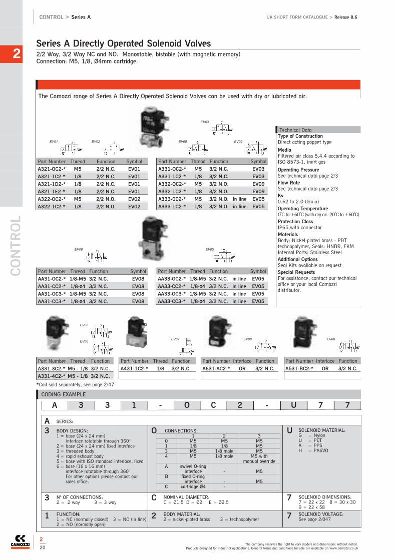
EV03
CONTR
OL
2
CONTROL > Series A UK SHORT FORM CATALOGUE > Release 8.6
2
20The company reserves the right to vary models and dimensions without notice.
Products designed for industrial applications. General terms and conditions for sale are available on www.camozzi.co.uk
2/2 Way, 3/2 Way NC and NO. Monostable, bistable (with magnetic memory)Connection: M5, 1/8, Ø4mm cartridge.
The Camozzi range of Series A Directly Operated Solenoid Valves can be used with dry or lubricated air.
Series A Directly Operated Solenoid Valves
CODING EXAMPLE
SERIES:
BODY DESIGN:1= base (24 x 24 mm)
interface rotatable through 360°2 = base (24 x 24 mm) fixed interface3 = threaded body4= rapid exhaust body5= base with ISO standard interface, fixed6 = base (16 x 16 mm)
interface rotatable through 360°For other options please contact oursales office.
A 3 3 1 - O C 2 - U 7 7
A3
3
1
O
C
2
U
7
7
N° OF CONNECTIONS:2 = 2 way 3 = 3 way
FUNCTION:1 = NC (normally closed) 3 = NO (in line)2 = NO (normally open)
NOMINAL DIAMETER:C = Ø1.5 D = Ø2 E = Ø2.5
BODY MATERIAL:2= nickel-plated brass 3 = technopolymer
SOLENOID MATERIAL:G = NylonU = PETA = PPSH = PA6VO
SOLENOID DIMENSIONS:7 = 22 x 22 8 = 30 x 309 = 22 x 58SOLENOID VOLTAGE:See page 2/047
Technical DataType of ConstructionDirect acting poppet type
MediaFiltered air class 5.4.4 according toISO 8573-1, inert gas
Operating PressureSee technical data page 2/3Flow RateSee technical data page 2/3Kv0.62 to 2.0 (l/min)Operating Temperature0oC to +60oC (with dry air -20oC to +60oC)Protection ClassIP65 with connectorMaterialsBody: Nickel-plated brass - PBTtechnopolymer, Seals: HNBR, FKMInternal Parts: Stainless SteelAdditional Options Seal Kits available on requestSpecial RequestsFor assistance, contact our technicaloffice or your local Camozzidistributor.
Part Number Thread Function
A331-3C2-* M5 - 1/8 3/2 N.C.
A331-4C2-* M5 - 1/8 3/2 N.C.
Part Number Thread Function
A431-1C2-* 1/8 3/2 N.C.
Part Number Interface Function
A531-BC2-* OR 3/2 N.C.
Part Number Thread Function Symbol
A321-OC2-* M5 2/2 N.C. EV01
A321-1C2-* 1/8 2/2 N.C. EV01
A321-1D2-* 1/8 2/2 N.C. EV01
A321-1E2-* 1/8 2/2 N.C. EV01
A322-OC2-* M5 2/2 N.O. EV02
A322-1C2-* 1/8 2/2 N.O. EV02
Part Number Thread Function Symbol
A331-OC2-* M5 3/2 N.C. EV03
A331-1C2-* 1/8 3/2 N.C. EV03
A332-OC2-* M5 3/2 N.O. EV09
A332-1C2-* 1/8 3/2 N.O. EV09
A333-0C2-* M5 3/2 N.O. in line EV05
A333-1C2-* 1/8 3/2 N.O. in line EV05
Part Number Thread Function Symbol
AA31-OC2-* 1/8-M5 3/2 N.C. EV08
AA31-CC2-* 1/8-Ø4 3/2 N.C. EV08
AA31-OC3-* 1/8-M5 3/2 N.C. EV08
AA31-CC3-* 1/8-Ø4 3/2 N.C. EV08
Part Number Thread Function Symbol
AA33-OC2-* 1/8-M5 3/2 N.C. in line EV05
AA33-CC2-* 1/8-Ø4 3/2 N.C. in line EV05
AA33-OC3-* 1/8-M5 3/2 N.C. in line EV05
AA33-CC3-* 1/8-Ø4 3/2 N.C. in line EV05
*Coil sold separately, see page 2/47
CONNECTIONS: 1 2 3
0 M5 M5 M51 1/8 1/8 M53 M5 1/8 male M54 M5 1/8 male M5 with
manual overrideA swivel O-ring
interface - M5B fixed O-ring
interface - M5C cartridge Ø4 -
EV01 EV02
EV03
EV05
EV05
EV08
EV08
Part Number Interface Function
A631-AC2-* OR 3/2 N.C.
EV08 EV08EV07
EV09

2
See full catalogue or CD rom for all dimensions.For technical advice contact our sales office or your local Camozzi distributor.
UK SHORT FORM CATALOGUE > Release 8.6 CONTROL > Series 6
2
21
2/2 Way, 3/2 Way, NC and NO Monostable.Connection: 1/8, 3/8, Ø4mm cartridge.
The Camozzi range of Series 6 Directly Operated Solenoid Valves can be used with dry or lubricated air.
Series 6 Directly Operated Solenoid Valves
Technical DataType of ConstructionDirect acting poppet type
MediaFiltered air, class 5.4.4 according toISO 8573-1, inert gas
Operating PressureSee technical data page 2/3
Flow RateSee technical data page 2/3
Kv1.2 to 8.0 (l/min)
Operating Temperature0oC to +80oC (with dry air -20oC to +80oC)
Protection ClassIP65 with connectorMaterialsBody: Nickel-plated brass - anodizedaluminium, Seals: NBR (FKM ondemand), Internal Parts: Stainless Steel
Additional Options Seal Kits available on requestSpecial RequestsFor assistance, contact our technicaloffice or your local Camozzidistributor.
Part Number Thread Function
638-150-A6* 1/8 N.C.
648-150-A6* 1/8 N.O.
Part Number Thread Function
638M-101-A6* 1/8 N.C.
63CM-101-A6* 1/8 - Ø4 N.C.
Part Number Interface Function
600-450-A6* Rotatable N.C.
600-457-A6* Fixed N.C.
*See voltage coding
Part Number Thread Function
623-15E-A6* 3/8 N.C.
623-15F-A6* 3/8 N.C.
623-15G-A6* 3/8 N.C.
CODING EXAMPLE
6 3 8 M - 105 - A 6 B
6
3
8
M
105
A
6
B
SOLENOID DIMENSIONS:6 = 32 x 32
CONNECTIONS:0 = Interface 8 = 1/83 = 3/8 C= cartridge Ø4
SOLENOID VOLTAGE:B= 24V 50/60 HzC= 48V 50/60 HzD= 110V 50/60 HzE = 220V 50/60 Hz2= 12V DC3= 24V DC4= 48V DC6= 110VDC
M = Manifold
N° OF CONNECTIONS AND FUNCTIONS:0 = interface 3 = 3 way NC1 = 2 way NO 4 = 3 way NO2 = 2 way NC
SERIES: 6 TYPE OF DESIGN OF BASE: 150= threaded body450= base with rotatable interface457 = base with fixed interface101 = single manifold102 = 2 - part manifold103 = 3 - part manifold104 = 4 - part manifold105 = 5 - part manifold106 = 6 - part manifold
107 = 7 - part manifold108 = 8 - part manifold109 = 9 - part manifold110 = 10 - part manifold111 = 11 - part manifold112 = 12 - part manifold113 = 13 - part manifold114 = 14 - part manifold115 = 15 - part manifold
COIL MATERIALS:A = PPS
EV03
EV05 EV08
EV08 EV01

CONTR
OL
2
The company reserves the right to vary models and dimensions without notice.Products designed for industrial applications. General terms and conditions for sale are available on www.camozzi.co.uk
CONTROL > Series UK SHORT FORM CATALOGUE > Release 8.6
2
22
CONTROL > Series CFB
2/2 Way Normally Closed (NC).
Series CFB Stainless Steel Solenoid Valves
Technical DataType of ConstructionDirect acting poppet type - servo-assisted with diaphragm
MediaAir, water, liquid and gaseous fluidswith max viscosity 37 cSt (5° E)
Operating PressureSee technical data page 2/3
KvSee technical data page 2/3
Operating Temperature-10oC to +140oC.
Response TimeON <15 msec - OFF <25 msec
Protection ClassIP65 with connectorMaterialsBody: Stainless steel 316LSeals: FKM (EPDM on demand)Internal Parts: Stainless steelSpecial RequestsFor assistance, contact our technicaloffice or your local Camozzidistributor.
CODING EXAMPLE
CFB - D 2 1 A - W X - B8 E
1
A
W
CFB
D
2
X
B8
E
BODY MATERIAL:X = Stainless Steel
SOLENOID DIMENSION:B8 = 30mm
CONNECTIONS:1 = 1/82 = 1/43 = 3/84 = 1/2
NOMINAL DIAMETER:Nominal DiameterA = 1.5mmB = 2mmC = 2.5mmE = 3mmF = 4mm
SERIES: CFB
OPERATION:D = direct
NO OF POSITIONS:2 = 2/2-way NC
SEAL MATERIALS:W = FKME = EPDM (on demand)
SOLENOID VOLTAGE:B= 24V AC 50HzD= 110V AC 50/60HzE = 230V AC 50/60Hz2= 12V DC3= 24V DC
Part Number Connection 24V AC 110V AC 220/230V AC 12V DC 24V DC
50 Hz 50/60 Hz 50/60 Hz
CFB-D21A-...X-* 1/8 B8B (15VA) B8D (15VA) B8E (15VA) B82 (19W) B83 (19W)
CFB-D21B-...X-* 1/8 B8B (15VA) B8D (15VA) B8E (15VA) B82 (19W) B83 (19W)
CFB-D21C-...X-* 1/8 B8B (15VA) B8D (15VA) B8E (15VA) B82 (19W) B83 (19W)
CFB-D22B-...X-* 1/4 B8B (15VA) B8D (15VA) B8E (15VA) B82 (19W) B83 (19W)
CFB-D22C-...X-* 1/4 B8B (15VA) B8D (15VA) B8E (15VA) B82 (19W) B83 (19W)
CFB-D22E-...X-* 1/4 B8B (15VA) B8D (15VA) B8E (15VA) B82 (19W) B83 (19W)
CFB-D23E-...X-* 3/8 B8B (15VA) B8D (15VA) B8E (15VA) B82 (19W) B83 (19W)
CFB-D23F-...X-* 3/8 B8B (15VA) B8D (15VA) B8E (15VA) B82 (19W) B83 (19W)
CFB-D24E-...X-* 1/2 B8B (15VA) B8D (15VA) B8E (15VA) B82 (19W) B83 (19W)
CFB-D24F-...X-* 1/2 B8B (15VA) B8D (15VA) B8E (15VA) B82 (19W) B83 (19W)
New
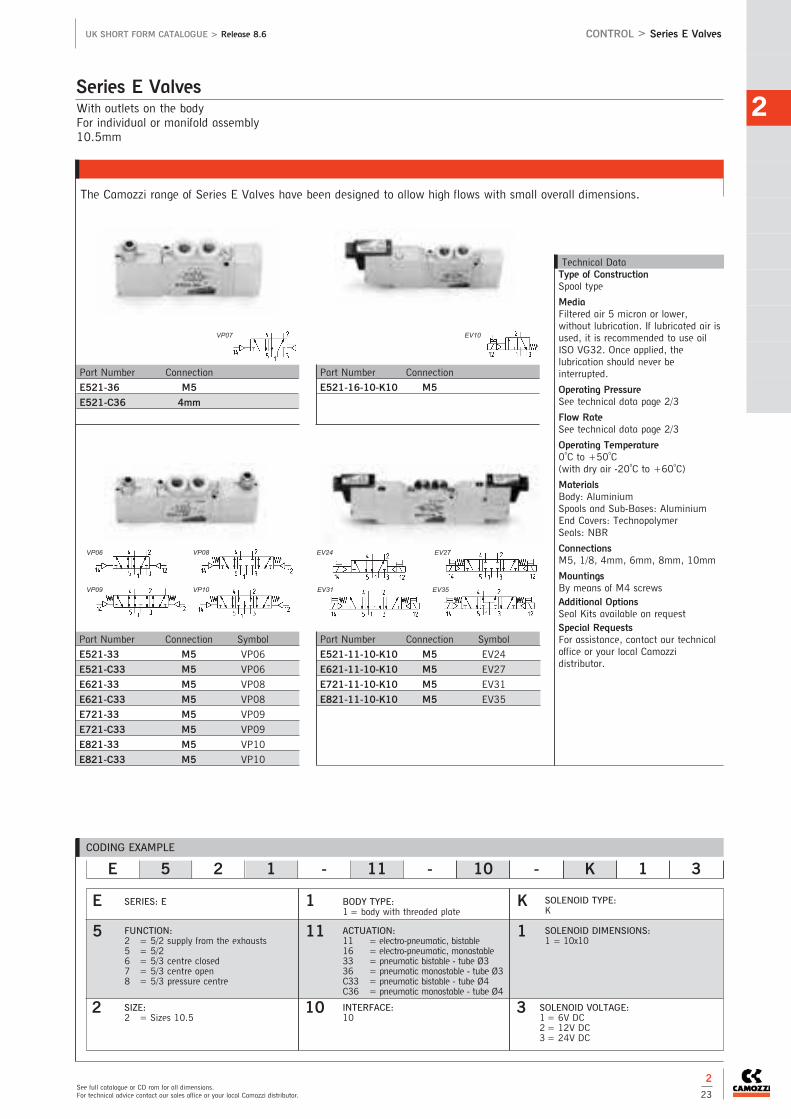
2
See full catalogue or CD rom for all dimensions.For technical advice contact our sales office or your local Camozzi distributor.
UK SHORT FORM CATALOGUE > Release 8.6 CONTROL > Series E Valves
2
23
With outlets on the bodyFor individual or manifold assembly10.5mm
The Camozzi range of Series E Valves have been designed to allow high flows with small overall dimensions.
Series E Valves
Technical DataType of ConstructionSpool type
MediaFiltered air 5 micron or lower,without lubrication. If lubricated air isused, it is recommended to use oilISO VG32. Once applied, thelubrication should never beinterrupted.
Operating PressureSee technical data page 2/3
Flow RateSee technical data page 2/3
Operating Temperature0oC to +50oC (with dry air -20oC to +60oC)
MaterialsBody: AluminiumSpools and Sub-Bases: AluminiumEnd Covers: TechnopolymerSeals: NBR
ConnectionsM5, 1/8, 4mm, 6mm, 8mm, 10mm
MountingsBy means of M4 screwsAdditional Options Seal Kits available on requestSpecial RequestsFor assistance, contact our technicaloffice or your local Camozzidistributor.
Part Number Connection
E521-36 M5
E521-C36 4mm
Part Number Connection
E521-16-10-K10 M5
Part Number Connection Symbol
E521-33 M5 VP06
E521-C33 M5 VP06
E621-33 M5 VP08
E621-C33 M5 VP08
E721-33 M5 VP09
E721-C33 M5 VP09
E821-33 M5 VP10
E821-C33 M5 VP10
Part Number Connection Symbol
E521-11-10-K10 M5 EV24
E621-11-10-K10 M5 EV27
E721-11-10-K10 M5 EV31
E821-11-10-K10 M5 EV35
CODING EXAMPLE
E 5 2 1 - 11 - 10 - K 1 3
1
11
10
SOLENOID TYPE:K
SOLENOID DIMENSIONS:1 = 10x10
INTERFACE:10
E
5
2
SERIES: E
FUNCTION:2 = 5/2 supply from the exhausts5 = 5/26 = 5/3 centre closed7 = 5/3 centre open8 = 5/3 pressure centre
SIZE:2 = Sizes 10.5
SOLENOID VOLTAGE:1= 6V DC2= 12V DC3= 24V DC
ACTUATION:11 = electro-pneumatic, bistable16 = electro-pneumatic, monostable33 = pneumatic bistable - tube Ø336 = pneumatic monostable - tube Ø3C33 = pneumatic bistable - tube Ø4C36 = pneumatic monostable - tube Ø4
K
1
3
BODY TYPE:1= body with threaded plate
VP07
VP06 VP08
VP09 VP10
EV10
EV31
EV24 EV27
EV35

Base mounted bodyFor individual or manifold assembly10.5mm
The Camozzi range of Series E Valves have been designed to allow high flows with small overall dimensions.
Series E Valves
CONTR
OL
2
CONTROL > Series E UK SHORT FORM CATALOGUE > Release 8.6
Technical DataType of ConstructionBalanced spool type
MediaFiltered air 5 micron or lower,without lubrication. If lubricated air isused, it is recommended to use oilISO VG32. Once applied, thelubrication should never beinterrupted.
Operating PressureSee technical data page 2/3
Flow RateSee technical data page 2/3
Operating Temperature0oC to +50oC
MaterialsBody: AluminiumSpools and Sub-Bases: AluminiumEnd Covers: TechnopolymerSeals: NBR
MountingsBy feet or screws to sub-bases
Additional Options Seal Kits available on requestSpecial RequestsFor assistance, contact our technicaloffice or your local Camozzidistributor.
Note: Base not included
Part Number Symbol
E520-11-10-K1* EV10
E620-11-10-K1* EV27
E720-11-10-K1* EV31
E820-11-10-K1* EV35
2
24
CODING EXAMPLE
E 5 2 0 - 11 - 10 - K 1 3
0
11
10
SOLENOID TYPE:K = solenoid (10x10)
SOLENOID DIMENSIONS:1 = 10x10
E
5
2
SERIES: E
FUNCTION:2 = 5/2 supply from the exhausts5 = 5/26 = 5/3 centre closed7 = 5/3 centre open8 = 5/3 pressure centre
ACTUATION:11 = electro-pneumatic, bistable16 = electro-pneumatic, monostable33 = pneumatic bistable - tube Ø336 = pneumatic monostable - tube Ø3
* C33 = pneumatic bistable - tube Ø4* C36 = pneumatic monostable - tube Ø4311 = electro-pneumatic bistable on
subbase or manifold316 = electro-pneumatic monostable on
subbase or manifold333 = pneumatic bistable on sub-base
or manifold336 = pneumatic monostable on
sub-base or manifold
K
1
3
BODY TYPE:0= body for sub-base
INTERFACE:10
SIZE:2 = Sizes 10.5
The company reserves the right to vary models and dimensions without notice.Products designed for industrial applications. General terms and conditions for sale are available on www.camozzi.co.uk
*on request.
Part Number Symbol
E520-33 VP06
E520-C33 VP06
E620-33 VP08
E620-C33 VP08
E720-33 VP09
E720-C33 VP09
E820-33 VP10
E820-C33 VP10
EV24
EV35EV31
EV27
Part Number
E520-36
E520-C36
Part Number
E520-16-10-K1*
*See voltage coding
VP07 EV10
VP06 VP08
VP09 VP10
SOLENOID VOLTAGE:* 1 = 6V DC* 2 = 12V DC
3 = 24V DC

2
See full catalogue or CD rom for all dimensions.For technical advice contact our sales office or your local Camozzi distributor.
UK SHORT FORM CATALOGUE > Release 8.6 CONTROL > Series E
2
25
Connections: 1/8
Single sub base for base mounted valves. Size 10.5
Series E Sub-Bases and Manifolds for Valves
Technical DataType of ConstructionMachined aluminium extrusion
MaterialsAluminium
ConnectionsSee sub-base and manifold codingSeries EMountingsBy means of screws supplied withvalvesSpecial RequestsFor assistance, contact our technicaloffice or your local Camozzidistributor.
Connections: 1/8
Manifolds for valves with outlets on the body. Size 10.5
Part Number Size Connection: 1, 3, 5, 2 and 4 Connection: 82, 84, 12 and 14
E520-0101 10.5 1/8 M5
Part Number Size Connection: 1, 3, 5Connection: 82, 84 Number of Positions
E521-10** 10.5 1/8 M5 02 04 06 08 10 12

Series E Sub-Bases and Manifolds for Valves
CONTR
OL
2
The company reserves the right to vary models and dimensions without notice.Products designed for industrial applications. General terms and conditions for sale are available on www.camozzi.co.uk
CONTROL > Series E UK SHORT FORM CATALOGUE > Release 8.6
Part Number Size Connection: 1, 3, 5Connection: 2, 4 Connection: 82, 84 Number of Positions
E520-21** 10.5 1/8 M5 M5 02 04 06 08 10 12
** = Number of positions
Connections: 1/8
Manifolds for base mounted valves.Size 10.5
2
26
CODING EXAMPLE
SERIES: E5
E5 2 1 - 1 0 04
E5
2
1
1
0
04
BODY TYPE:0= body for sub-base assembly1 = body with threads or tube connection
TYPE OF SUB-BASE:0= single sub-base with side outlets1 = manifold for threaded valve2 = manifold for body mounted valve3 = manifold for threaded valve with
externally supplied pilots4 = manifold for body mounted valve with
externally supplied pilots
CONNECTIONS:0 = for valves with outlets on the body1 = threadedC = tube 4 (size 10,5)
NO OF POSITIONS:01 = single03, 04, 06, 08, 10, 12 = multiple
SIZE:2 = Size 10.5
NOTE: When constructing manifolds with 10 or more stations, it is recommended, in order to reduce the risk of pressure drop within the assembly, thatpressure is supplied to connection 1 at each end of the block. The exhaust connection 3 and 5 at each end should also be utilized (size 10.5 and 16mm).The same provision should be made for 5 station manifolds of the 19mm valves. Manifolds complete with connections for external pilot supply are availableon request.

2
See full catalogue or CD rom for all dimensions.For technical advice contact our sales office or your local Camozzi distributor.
UK SHORT FORM CATALOGUE > Release 8.6 CONTROL > Series E
2
27
Series E Accessories for Valves
Threaded valves
Part Number Size
TP-E521 10.5
TP-E520 10.5
Blanking plate for manifolds.
Threaded valves
Part Number Size
PCP-E521 10.5
PCP-E520 10.5Intermediate plate for manifoldsfor valves with separate supply in 1.
Threaded valves
Part Number Size
PCS-E521 10.5
PCS-E520 10.5Intermediate plate for manifolds forvalves with separate supply in 3 and 5.
Part NumberPCF-E520Suitable for all manifolds
Mounting brackets for DIN rail
channel DIN EN 50022
(7.5 x 35 with 1mm).
Part Number
B1-E521 for valves size 10.5Horizontal feet for valves with outlets on thebody.
Part Number
B2-E521 for valves size 10.5Vertical feet for valves with outlets on thebody (monostable only).

5/2 way, 5/3 way CC - CO - CPWith outlets on the body - For individual or manifold assemblySize 16 - 19 mm
Series EN Valves and Solenoid Valves
CONTR
OL
2
The company reserves the right to vary models and dimensions without notice.Products designed for industrial applications. General terms and conditions for sale are available on www.camozzi.co.uk
CONTROL > Series EN UK SHORT FORM CATALOGUE > Release 8.6
Part Number
EN531-33
EN551-33
Part Number
EN531-36
EN551-36
Part Number
EN731-33
EN751-33
Part Number
EN831-33
EN851-33
Part Number
EN631-33
EN651-33
2
28
Part Number
EN531-E16-P*
EN551-E16-P*
EN531-E16-W*
EN551-E16-W*
Part Number
EN531-16-P*
EN551-16-P*
EN531-16-W*
EN551-16-W*
Part Number
EN531-E11-P*
EN551-E11-P*
EN531-E11-W*
EN551-E11-W*
Part Number
EN531-11-P*
EN551-11-P*
EN531-11-W*
EN551-11-W*
Technical DataType of ConstructionSpool type
MediaFiltered air, without lubrication. If lubricated air is used, it isrecommended to use oil ISO VG32.Once applied, the lubrication shouldnever be interrupted.
Operating PressureSee technical data page 2/4
Flow RateSee technical data page 2/4
Operating Temperature0oC to +50oC
MaterialsBody: AluminiumSpools and Sub-Bases: AluminiumEnd Covers: TechnopolymerSeals: NBR
Connections1/8, 1/4
MountingsBy feet or screws to sub-basesAdditional Options Seal Kits available on request
VP07 VP06
VP08 VP09 VP10
EV21 EV22 EV23 EV26
EV21 EV22 EV23 EV26
Part Number
EN531-E16-PN*
EN551-E16-PN*
Part Number
EN531-16-PN*
EN551-16-PN*
Part Number
EN531-E11-PN*
EN551-E11-PN*
Part Number
EN531-11-PN*
EN551-11-PN*

2
See full catalogue or CD rom for all dimensions.For technical advice contact our sales office or your local Camozzi distributor.
UK SHORT FORM CATALOGUE > Release 8.6 CONTROL > Series EN
Series EN Valves and Solenoid Valves
2
29
Part Number
EN731-11-PN*
EN751-11-PN*
Part Number
EN831-11-PN*
EN851-11-PN*
Part Number
EN631-11-PN*
EN651-11-PN*
Part Number
EN731-E11-PN*
EN751-E11-PN*
Part Number
EN831-E11-PN*
EN851-E11-PN*
Part Number
EN631-E11-PN*
EN651-E11-PN*
CODING EXAMPLE
SERIES: EN
EN 5 3 1 - 11 - PN3
EN
5 FUNCTION 5 = 5/26 = 5/3 Centre Closed7 = 5/3 Centre Open8 = 5/3 Pressure Centre
3
1
SIZES:3 = 16mm5 = 19mm
BODY TYPE:1 = body with threaded plate
11
PN3
ACTUATION:11 = electro-pneumatic,
bistable16 = electro-pneumatic,
monostable33 = pneumatic bistable36 = pneumatic monostable
E11 = electro-pneumatic,bistable with externalservo-pilot supply
E16 = electro-pneumatic,monostable withexternal servo-pilotsupply
TYPE OF SOLENOIDPN3 = 24V DC - 1WPN4 = 48V DC - 2WPN6 = 110V DC - 2WPN7 = 230V - 2W
P13 = 24V DC - 1WP54 = 48V DC - 2WP56 = 110V DC - 2WW53 = 24V DC - 2WW54 = 48V DC - 2W
In case of applications with alternate current, use a bridge rectifier connector
EV28
EV38
EV36
EV30
EV32
EV33
Part Number
EN731-11-P*
EN751-11-P*
EN731-11-W*
EN751-11-W*
Part Number
EN831-11-P*
EN851-11-P*
EN831-11-W*
EN851-11-W*
Part Number
EN631-11-P*
EN651-11-P*
EN631-11-W*
EN651-11-W*
Part Number
EN731-E11-P*
EN751-E11-P*
EN731-E11-W*
EN751-E11-W*
Part Number
EN831-E11-P*
EN851-E11-P*
EN831-E11-W*
EN851-E11-W*
Part Number
EN631-E11-P*
EN651-E11-P*
EN631-E11-W*
EN651-E11-W*
EV28
EV38
EV36
EV30
EV32
EV33

5/2 way, 5/3 way CC - CO - CPFor manifold assemblySize 16 - 19 mm
Series EN Valves and Solenoid Valves
CONTR
OL
2
The company reserves the right to vary models and dimensions without notice.Products designed for industrial applications. General terms and conditions for sale are available on www.camozzi.co.uk
CONTROL > Series EN UK SHORT FORM CATALOGUE > Release 8.6
2
30
Technical DataType of ConstructionSpool type
MediaFiltered air, without lubrication. If lubricated air is used, it isrecommended to use oil ISO VG32.Once applied, the lubrication shouldnever be interrupted.
Operating PressureSee technical data page 2/4
Flow RateSee technical data page 2/4
Operating Temperature0oC to +50oC
MaterialsBody: AluminiumSpools and Sub-Bases: AluminiumEnd Covers: TechnopolymerSeals: NBR
Connections1/8, 1/4
MountingsBy feet or screws to sub-basesAdditional Options Seal Kits available on request
Part Number
EN530-33
EN550-33
Part Number
EN530-36
EN550-36
Part Number
EN730-33
EN750-33
Part Number
EN830-33
EN850-33
Part Number
EN630-33
EN650-33
Part Number
EN530-E16-P*
EN550-E16-P*
EN530-E16-W*
EN550-E16-W*
Part Number
EN530-16-P*
EN550-16-P*
EN530-16-W*
EN550-16-W*
Part Number
EN530-E11-P*
EN550-E11-P*
EN530-E11-W*
EN550-E11-W*
Part Number
EN530-11-P*
EN550-11-P*
EN530-11-W*
EN550-11-W*
VP07 VP06
VP08 VP09 VP10
EV21 EV22 EV23 EV26
EV21 EV22 EV23 EV26
Part Number
EN530-E16-PN*
EN550-E16-PN*
Part Number
EN530-16-PN*
EN550-16-PN*
Part Number
EN530-E11-PN*
EN550-E11-PN*
Part Number
EN530-11-PN*
EN550-11-PN*
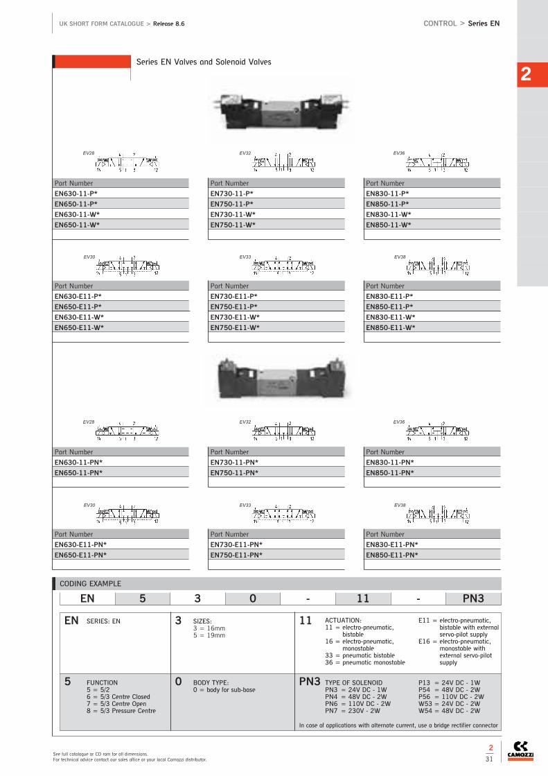
2
See full catalogue or CD rom for all dimensions.For technical advice contact our sales office or your local Camozzi distributor.
UK SHORT FORM CATALOGUE > Release 8.6 CONTROL > Series EN
2
31
CODING EXAMPLE
SERIES: EN
EN 5 3 0 - 11 - PN3
EN
5 FUNCTION 5 = 5/26 = 5/3 Centre Closed7 = 5/3 Centre Open8 = 5/3 Pressure Centre
3
0
SIZES:3 = 16mm5 = 19mm
BODY TYPE:0 = body for sub-base
11
PN3
ACTUATION:11 = electro-pneumatic,
bistable16 = electro-pneumatic,
monostable33 = pneumatic bistable36 = pneumatic monostable
E11 = electro-pneumatic,bistable with externalservo-pilot supply
E16 = electro-pneumatic,monostable withexternal servo-pilotsupply
TYPE OF SOLENOIDPN3 = 24V DC - 1WPN4 = 48V DC - 2WPN6 = 110V DC - 2WPN7 = 230V - 2W
P13 = 24V DC - 1WP54 = 48V DC - 2WP56 = 110V DC - 2WW53 = 24V DC - 2WW54 = 48V DC - 2W
In case of applications with alternate current, use a bridge rectifier connector
Series EN Valves and Solenoid Valves
Part Number
EN730-11-PN*
EN750-11-PN*
Part Number
EN830-11-PN*
EN850-11-PN*
Part Number
EN630-11-PN*
EN650-11-PN*
Part Number
EN730-E11-PN*
EN750-E11-PN*
Part Number
EN830-E11-PN*
EN850-E11-PN*
Part Number
EN630-E11-PN*
EN650-E11-PN*
EV28
EV38
EV36
EV30
EV32
EV33
Part Number
EN730-11-P*
EN750-11-P*
EN730-11-W*
EN750-11-W*
Part Number
EN830-11-P*
EN850-11-P*
EN830-11-W*
EN850-11-W*
Part Number
EN630-11-P*
EN650-11-P*
EN630-11-W*
EN650-11-W*
Part Number
EN730-E11-P*
EN750-E11-P*
EN730-E11-W*
EN750-E11-W*
Part Number
EN830-E11-P*
EN850-E11-P*
EN830-E11-W*
EN850-E11-W*
Part Number
EN630-E11-P*
EN650-E11-P*
EN630-E11-W*
EN650-E11-W*
EV28
EV38
EV36
EV30
EV32
EV33

CONTR
OL
2
The company reserves the right to vary models and dimensions without notice.Products designed for industrial applications. General terms and conditions for sale are available on www.camozzi.co.uk
CONTROL > Series EN UK SHORT FORM CATALOGUE > Release 8.6
Series EN Accessories
2
32
Connectors 24DC PN with led for solenoid P and PN
Conn. V-AC PN with bridge rectifier for solenoid P and PN
In-line connectors with cable Connectors DIN 43650
Mounting brackets
Manifold for valves size 16 and 19(with outlets on the manifold)
Blanking plate for manifolds(with outlets on the body)
Blanking plate for manifolds -base mounted valves
Sub-base for valves size 16 and 19 (with outlets on the body)
Part Number Cable Length
125-503-2 2m
125-503-5 5m
Part Number Cable Length
125-903-2 2m
125-903-5 5m
Part Number Cable Length
125-553-2 2m
125-553-5 5m
Part Number
PCF-EN531
Part Number Description
KD136000B7 Black Connector PG7 9.4mm Pin Spacing
KC136000B7 Black Connector PG7 8mm Pin Spacing
Part Number Size
TP-EN531 16
TP-EN551 19
Part Number Size
TP-EN530 16
TP-EN550 19
Part Number No. of Part Number No. of
Valve Positions Valve Positions
EN531-1002 2 EN551-1002 2
EN531-1003 3 EN551-1003 3
EN531-1004 4 EN551-1004 4
EN531-1005 5 EN551-1005 5
EN531-1006 6 EN551-1006 6
EN531-1008 8 EN551-1008 8
EN531-1010 10 EN551-1010 10
EN531-1012 12 EN551-1012 12
Part Number No. of Part Number No. of
Valve Positions Valve Positions
EN530-2102 2 EN550-2102 2
EN530-2103 3 EN550-2103 3
EN530-2104 4 EN550-2104 4
EN530-2105 5 EN550-2105 5
EN530-2106 6 EN550-2106 6
EN530-2108 8 EN550-2108 8
EN530-2110 10 EN550-2110 10
EN530-2112 12 EN550-2112 12
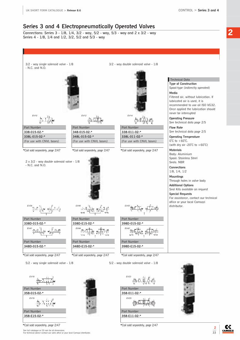
2
UK SHORT FORM CATALOGUE > Release 8.6 CONTROL > Series 3 and 4
*Coil sold separately, page 2/47 *Coil sold separately, page 2/47
Connections: Series 3 - 1/8, 1/4, 3/2 - way, 5/2 - way, 5/3 - way and 2 x 3/2 - waySeries 4 - 1/8, 1/4 and 1/2, 3/2, 5/2 and 5/3 - way
Series 3 and 4 Electropneumatically Operated Valves
Technical DataType of ConstructionSpool-type (indirectly operated)
MediaFiltered air, without lubrication. Iflubricated air is used, it isrecommended to use oil ISO VG32.Once applied the lubrication shouldnever be interrupted
Operating PressureSee technical data page 2/5
Flow RateSee technical data page 2/5
Operating Temperature0oC to +60oC. (with dry air -20oC to +60oC)
MaterialsBody: AluminiumSpool: Stainless SteelSeals: NBR
Connections1/8, 1/4, 1/2
MountingsThrough holes in valve body
Additional Options Seal Kits available on request
Special RequestsFor assistance, contact our technicaloffice or your local Camozzidistributor.
Part Number
348-015-02-*
348L-015-02-*
(For use with CNVL bases)
Part Number
338-011-02-*
338L-011-02-*
(For use with CNVL bases)
Part Number
338-015-02-*
338L-015-02-*
(For use with CNVL bases)
Part Number
338D-E15-02-*
Part Number
348D-E15-02-*
Part Number
398D-015-02-*
Part Number
398D-E15-02-*
Part Number
338D-015-02-*
Part Number
348D-015-02-*
Part Number
358-011-02-*
Part Number
358-E11-02-*
Part Number
358-015-02-*
Part Number
358-E15-02-*
3/2 - way single solenoid valve - 1/8- N.C. and N.O.
2 x 3/2 - way double solenoid valve - 1/8- N.C. and N.O.
3/2 - way double solenoid valve - 1/8
*Coil sold separately, page 2/47 *Coil sold separately, page 2/47 *Coil sold separately, page 2/47
*Coil sold separately, page 2/47 *Coil sold separately, page 2/47 *Coil sold separately, page 2/47
5/2 - way single solenoid valve - 1/8 5/2 - way double solenoid valve - 1/8
2
33
EV10 EV12 EV14
EV43
EV42EV44EV41
EV40EV39
EV18
EV19
EV23
EV25
See full catalogue or CD rom for all dimensions.For technical advice contact our sales office or your local Camozzi distributor.

CONTR
OL
2
The company reserves the right to vary models and dimensions without notice.Products designed for industrial applications. General terms and conditions for sale are available on www.camozzi.co.uk
CONTROL > Series 3 UK SHORT FORM CATALOGUE > Release 8.6
Series 3 Electropneumatically Operated Valves
Part Number
378-011-02-*
Part Number
378-E11-02-*
*Coil sold separately, page 2/47
Part Number
368-011-02-*
Part Number
368-E11-02-*
*Coil sold separately, page 2/47
Part Number
334-011-02-*
Part Number
334-E11-02-**Coil sold separately, page 2/47
Part Number
334-015-02-*
Part Number
334-E15-02-*
Part Number
344-015-02-*
Part Number
344-E15-02-**Coil sold separately, page 2/47
Part Number
388-011-02-*
Part Number
388-E11-02-*
*Coil sold separately, page 2/47
3/2 - way single solenoid valve - 1/4 -N.C. and N.O.
3/2 - way double solenoid valve - 1/4
5/3 - way double solenoid valve - 1/8 - centres closed, centres open and pressure centres
2
34
EV28 EV36EV32
EV29 EV34 EV37
EV10
EV11
EV12
EV13
EV14
EV15

2
See full catalogue or CD rom for all dimensions.For technical advice contact our sales office or your local Camozzi distributor.
UK SHORT FORM CATALOGUE > Release 8.6 CONTROL > Series 3
Series 3 Electropneumatically Operated Valves
Part Number
344D-015-02-*
Part Number
344D-E15-02-**Coil sold separately, page 2/47
Part Number
334D-015-02-*
Part Number
334D-E15-02-**Coil sold separately, page 2/47
Part Number
354-011-02-*
Part Number
354-E11-02-**Coil sold separately, page 2/47
Part Number
354-015-02-*
Part Number
354-E15-02-**Coil sold separately, page 2/47
Part Number
394D-015-02-*
Part Number
394D-E15-02-**Coil sold separately, page 2/47
2 x 3/2 - way double solenoid valve - 1/4 -N.C. and N.O.
5/2 - way single solenoid valve - 1/4 5/2 - way double solenoid valve - 1/4
2
35
EV25
EV18
EV19
EV23
EV25
EV43
EV42EV44
EV41
EV40
EV39

CONTR
OL
2
The company reserves the right to vary models and dimensions without notice.Products designed for industrial applications. General terms and conditions for sale are available on www.camozzi.co.uk
CONTROL > Series 3 UK SHORT FORM CATALOGUE > Release 8.6
Series 3 Electropneumatically Operated Valves
Part Number
438-011-22-*
*Coil sold separately, page 2/47
Part Number
458-015-22-*
Part Number
458-016-22-*
*Coil sold separately, page 2/47
Part Number
438-015-22-*
Part Number
438-016-22-*
*Coil sold separately, page 2/47
Part Number
458-011-22-*
*Coil sold separately, page 2/47
Part Number
374-011-02-*
Part Number
374-E11-02-**Coil sold separately, page 2/47
Part Number
364-011-02-*
Part Number
364-E11-02-**Coil sold separately, page 2/47
Part Number
384-011-02-*
Part Number
384-E11-02-**Coil sold separately, page 2/47
5/3 - way double solenoid valve - 1/4 - centres closed, centres open and pressurecentres
3/2 - way single solenoid valve - 1/8 - N.C.
3/2 - way double solenoid valve - 1/8 - N.C.
5/2 - way single solenoid valve - 1/8
5/2 - way double solenoid valve - 1/8
Series 4 Electropneumatically Operated Valves
2
36
EV28 EV36EV32
EV29 EV34 EV37
EV10 EV14
EV16
EV18
EV21
EV23

2
See full catalogue or CD rom for all dimensions.For technical advice contact our sales office or your local Camozzi distributor.
UK SHORT FORM CATALOGUE > Release 8.6 CONTROL > Series 4
Series 4 Electropneumatically Operated Valves
Part Number
434-015-22-*
Part Number
434-016-22-*
*Coil sold separately, page 2/47
Part Number
434-011-22-*
*Coil sold separately, see page 2/47
Part Number
468-011-22-*
Part Number
478-011-22-*
*Coil sold separately, page 2/47
Part Number
454-015-22-*
Part Number
454-016-22-*
*Coil sold separately, page 2/47
Part Number
454-V15-22-*
Part Number
454-V16-22-*
*Coil sold separately, page 2/47
Part Number
454-V11-22-*
*Coil sold separately, page 2/47
Part Number
454-011-22-*
*Coil sold separately, page 2/47
Part Number
464-011-22-*
Part Number
474-011-22-*
*Coil sold separately, page 2/47
5/3 - way double solenoidvalve - 1/8 - centres closed
3/2 - way single solenoidvalve - 1/4 - N.C.
5/2 - way singlesolenoid valve - 1/4
3/2 - way double solenoidvalve - 1/4 - N.C.
5/2 - way doublesolenoid valve - 1/4
5/2 - way single verticalsolenoid valve - 1/4
5/3 - way double solenoidvalve - 1/4 - centres closedand centre open
5/2 - way double verticalsolenoid valve - 1/4
2
37
EV32
EV23 EV23
EV28 EV10
EV16
EV14 EV18
EV21
EV18
EV21
EV28
EV32
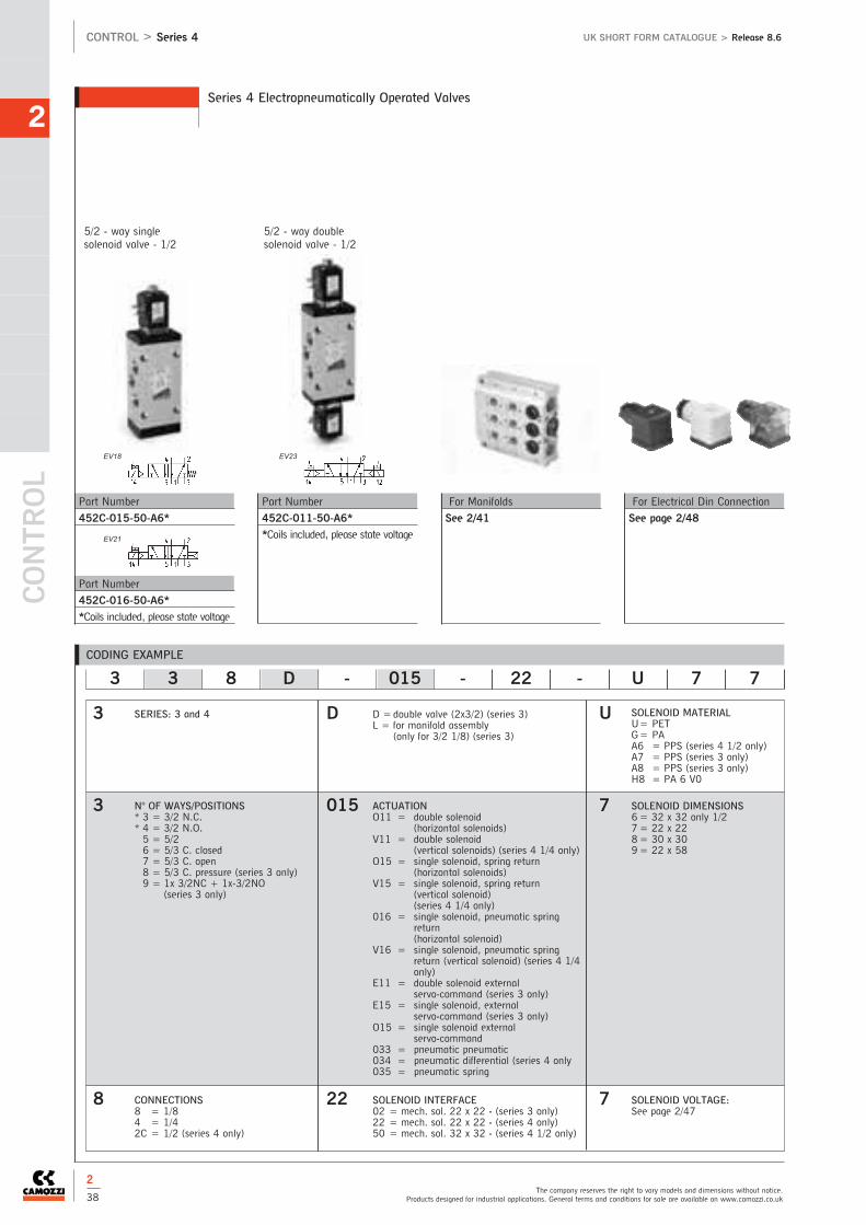
CONTR
OL
2
The company reserves the right to vary models and dimensions without notice.Products designed for industrial applications. General terms and conditions for sale are available on www.camozzi.co.uk
CONTROL > Series 4 UK SHORT FORM CATALOGUE > Release 8.6
Series 4 Electropneumatically Operated Valves
Part Number
452C-011-50-A6*
*Coils included, please state voltage
For Manifolds
See 2/41
For Electrical Din Connection
See page 2/48
Part Number
452C-015-50-A6*
Part Number
452C-016-50-A6*
*Coils included, please state voltage
5/2 - way singlesolenoid valve - 1/2
5/2 - way doublesolenoid valve - 1/2
2
38
CODING EXAMPLE
SERIES: 3 and 4
N° OF WAYS/POSITIONS* 3 = 3/2 N.C.* 4 = 3/2 N.O.5 = 5/26 = 5/3 C. closed7 = 5/3 C. open8 = 5/3 C. pressure (series 3 only)9 = 1x 3/2NC + 1x-3/2NO
(series 3 only)
3 3 8 D - 015 - 22 - U 7 7
3
3
8
D
015
22
U
7
7
D =double valve (2x3/2) (series 3)L = for manifold assembly
(only for 3/2 1/8) (series 3)
SOLENOID MATERIAL U= PETG= PAA6 = PPS (series 4 1/2 only)A7 = PPS (series 3 only)A8 = PPS (series 3 only)H8 = PA 6 V0
SOLENOID DIMENSIONS 6= 32 x 32 only 1/27= 22 x 228= 30 x 309= 22 x 58
ACTUATIONO11 = double solenoid
(horizontal solenoids)V11 = double solenoid
(vertical solenoids) (series 4 1/4 only)O15 = single solenoid, spring return
(horizontal solenoids)V15 = single solenoid, spring return
(vertical solenoid) (series 4 1/4 only)
016 = single solenoid, pneumatic springreturn (horizontal solenoid)
V16 = single solenoid, pneumatic springreturn (vertical solenoid) (series 4 1/4only)
E11 = double solenoid externalservo-command (series 3 only)
E15 = single solenoid, externalservo-command (series 3 only)
O15 = single solenoid external servo-command
033 = pneumatic pneumatic034 = pneumatic differential (series 4 only035 = pneumatic spring
CONNECTIONS8 = 1/84 = 1/42C = 1/2 (series 4 only)
SOLENOID INTERFACE02 = mech. sol. 22 x 22 - (series 3 only)22 = mech. sol. 22 x 22 - (series 4 only)50 = mech. sol. 32 x 32 - (series 4 1/2 only)
SOLENOID VOLTAGE:See page 2/47
EV23EV18
EV21
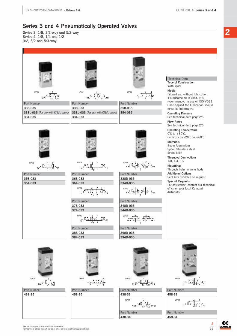
Series 3: 1/8, 3/2-way and 5/2-waySeries 4: 1/8, 1/4 and 1/23/2, 5/2 and 5/3-way
Series 3 and 4 Pneumatically Operated Valves2
See full catalogue or CD rom for all dimensions.For technical advice contact our sales office or your local Camozzi distributor.
UK SHORT FORM CATALOGUE > Release 8.6 CONTROL > Series 3 and 4
Technical DataType of ConstructionWith spool
MediaFiltered air, without lubrication. If lubricated air is used, it isrecommended to use oil ISO VG32.Once applied the lubrication shouldnever be interrupted.
Operating PressureSee technical data page 2/6
Flow RatesSee technical data page 2/6
Operating Temperature0oC to +80oC. (with dry air -20oC to +60oC)
MaterialsBody: AluminiumSpool: Stainless steelSeals: NBR
Threaded Connections1/8, 1/4, 1/2
MountingsThrough holes in valve bodyAdditional Options Seal Kits available on requestSpecial RequestsFor assistance, contact our technicaloffice or your local Camozzidistributor.
Part Number
338-033
338L-033 (For use with CNVL bases)
334-033
Part Number
358-035
354-035
Part Number
338-035
338L-035 (For use with CNVL bases)
334-035
Part Number
368-033
364-033
Part Number
378-033
374-033
Part Number
388-033
384-033
Part Number
358-033
354-033
Part Number
458-35
Part Number
438-33
Part Number
438-34
Part Number
438-35
Part Number
458-33
Part Number
458-34
Part Number
338D-035
334D-035
Part Number
348D-035
344D-035
Part Number
398D-035
394D-035
2
39
VP01 VP02 VP04
VP06 VP08
VP09
VP10
VP11
VP12
VP13
VP01 VP02VP04 VP06
VP03 VP05

CONTR
OL
2
The company reserves the right to vary models and dimensions without notice.Products designed for industrial applications. General terms and conditions for sale are available on www.camozzi.co.uk
CONTROL > Series 3 and 4 UK SHORT FORM CATALOGUE > Release 8.6
Series 3 and 4 Pneumatically Operated Valves
Part Number
468-33
Part Number
454-35
Part Number
434-33
Part Number
434-34
Part Number
434-35
Part Number
454-33
Part Number
454-34
Part Number
452C-34
Part Number
452C-35
Part Number
452C-33
Part Number
464-33
Part Number
474-33
2
40
CODING EXAMPLE
3 5 8 - 035
3
5
8
035N° OF WAYS/POSITIONS3 = 3/25 = 5/26 = 5/3 C.C.7 = 5/3 C.O.
ACTUATION/RETURN033 = pneumatic / pneumatic (series 3)33 = pneumatic / pneumatic (series 4)34 = pneumatic / differential (series4)35 = pneumatic / spring (series 4)035 = pneumatic / spring (series 3)
SERIES: 3, 4 CONNECTIONS8 = 1/84 = 1/42C = 1/2
VP01 VP02VP04
VP04
VP06
VP06
VP03 VP05
VP05VP08 VP08
VP09

2
See full catalogue or CD rom for all dimensions.For technical advice contact our sales office or your local Camozzi distributor.
UK SHORT FORM CATALOGUE > Release 8.6 CONTROL > Series 3
Series 3 Modular Manifolds - 1/8 and 1/4
Basic Module with Two Positions
CNVL-3H2 to suit series 3, 1/8
CNVL-4H2 to suit series 3, 1/4
The packaging contains the following items: 3 O-rings, 2 Fixing Screws and 2 Junction plugs per station.
Basic Module with Three Positions
CNVL-3H3 to suit series 3, 1/8
CNVL-4H3 to suit series 3, 1/4
The packaging contains the following items: 3 O-rings, 2 Fixing Screws and 2 Junction plugs per station.
G3/8
G3/8
Expansion Module with Three Positions
CNVL-3I3 to suit series 3, 1/8
CNVL-4I3 to suit series 3, 1/4
The packaging contains the following items: 3 O-rings, 2 Fixing Screws and 2 Junction plugs.
2
41

CONTR
OL
2
CONTROL > Series 3 and 4 UK SHORT FORM CATALOGUE > Release 8.6
Series 3 Modular Manifolds - 1/8 and 1/4
The company reserves the right to vary models and dimensions without notice.Products designed for industrial applications. General terms and conditions for sale are available on www.camozzi.co.uk
2
42
Expansion Module with Two Positions
CNVL-3I2 to suit series 3, 1/8
CNVL-4I2 to suit series 3, 1/4
The packaging contains the following items: 3 O-rings, 2 Fixing Screws and 2 Junction plugs.
Terminal Module
CNVL-3H to suit series 3, 1/8
CNVL-4H to suit series 3, 1/4
The packaging contains the following items: 2 Junction plugs per station.
Expansion Module with One Position
CNVL-3I1 to suit series 3, 1/8
CNVL-4I1 to suit series 3, 1/4
The packaging contains the following items: 3 O-rings, 2 Fixing Screws and 2 Junction plugs.
G3/8

2
See full catalogue or CD rom for all dimensions.For technical advice contact our sales office or your local Camozzi distributor.
UK SHORT FORM CATALOGUE > Release 8.6 CONTROL > Series 3 and 4
Part Number
CNVL-3H-TP
CNVL-4H-TP
Code for Plug-in Versions
T Supply (1) + exhaust (3 and 5)
U Supply (1)
J Exhausts (3 and 5)
Intermediate plate for manifolds with outlets
CNVL-3P
CNVL-4P
The packaging contains the following items: 3 O-rings and 2 Fixing
Screws
G1/4
Interface Module Manifolds between 1/4 and 1/8 (Series 3)
CNVL-4H-3H
Excluder
CNVL/1L Code L
The packaging contains the following items: 3 O-rings and 2 Fixing Screws
Blanking Plate for Manifolds with outlets
CNVL/1 For Series 3 - 1/8
CNVL/2 For Series 4 - 1/8
CNVL/3 For Series 4 - 1/4
CNVL/4 For Series 3 - 1/4
Blanking Plug for CNVL... Manifolds. For use with 3/2- way valves
TCNVL/3 for 1/8
TCNVL/5 for 1/4
Part Number: CNVL/1 Part Number: CNVL/2 Part Number: CNVL/3
Accessories
2
43

Assembly with sub-base (ISO 5599/1 Standards)Size 1, 2 and 35/2 and 5/3 way CC CO
Series 9 Electropneumatically and Pneumatically Operated Valves
CONTR
OL
2
The company reserves the right to vary models and dimensions without notice.Products designed for industrial applications. General terms and conditions for sale are available on www.camozzi.co.uk
CONTROL > Series 9 UK SHORT FORM CATALOGUE > Release 8.6
Technical DataType of ConstructionSpool-type (Servo controlled)
MediaFiltered air, without lubrication. Iflubricated air is used, it isrecommended to use oil ISO VG32.Once applied the lubrication shouldnever be interrupted
Operating PressureSee technical data page 2/6
Flow RatesSee technical data page 2/6
Operating Temperature0oC to +60oC. (with dry air -20oC to+60oC)
MaterialsBody: AluminiumSpool: Stainless steelSeal: NBR
MountingsThreaded holes in sub-base
Additional Options Seal Kits available on requestSpecial RequestsFor assistance, contact our technicaloffice or your local Camozzidistributor.
Part Number
951-000-P16-23-*
952-000-P16-23-*
953-000-P16-23-*
*Coil sold separately, page 2/47
Part Number
951-000-P15-23-*
952-000-P15-23-*
953-000-P15-23-*
*Coil sold separately, page 2/47
Part Number
961-000-P11-23*
962-000-P11-23*
963-000-P11-23*
*Coil sold separately, page 2/47
Part Number
971-000-P11-23*
972-000-P11-23*
973-000-P11-23*
*Coil sold separately, page 2/47
Part Number
951-000-P11-23*
952-000-P11-23*
953-000-P11-23*
*Coil sold separately, page 2/47
Part Number
951-000-34
952-000-34
953-000-34
Part Number
951-000-35
952-000-35
953-000-35
Part Number
951-000-33
952-000-33
953-000-33
Part Number
971-000-33
972-000-33
973-000-33
Part Number
961-000-33
962-000-33
963-000-33
2
44
EV18 EV20
EV23 EV28 EV32
VP06 VP05 VP04
VP08 VP09

2
See full catalogue or CD rom for all dimensions.For technical advice contact our sales office or your local Camozzi distributor.
UK SHORT FORM CATALOGUE > Release 8.6 CONTROL > Series 9
*Complete with two end-blocks Part Number 90*-H** or 90*-HN*.
Single Sub-base with Rear Outlets
Size
901-G1A 1
902-G2A 2
903-G3A 3
Manifold sub-base with commonexhausts and inlet with outletconnection on rear
Size
901-C1A 1
902-C2A 2
903-C3A 3
Single Sub-base with Side Outlets
Size
901-F1A 1
902-F2A 2
903-F3A 3
End Block for manifold Sub-base
Size
901-H1* 1
902-H2* 2
903-H3* 3
*Pair
Manifold Sub-base with commoninlet and exhaust connection andwith outlet connection on the front
Size
901-N1A 1
End Block for manifold bases
with front outlets
Size
901-HN1 1
End Block with Front Outlet
Size
901-N1 1
902-N2 2
903-N3 3
Sub-base for Series 9
Mounting
901-C1A-TP
902-C2A-TP
Separation Joint
901-N1A-T
Cover Plate for Unused Positions
901-TP
Separation Joint
901-N1A/TP
2
45
CODING EXAMPLE
SERIES: 9
9 5 1 - C 1 B - P16 - 23 - U 7 7 - S
9
5
1
C
U
7
7
CONNECTIONS (OUTLETS):Size 1 = 1/4Size 2 = 3/8Size 3 = 1/2
SOLENOID MATERIAL:U = PPS A8 = PPSG= Nylon H8 = PA6VO
SOLENOID DIMENSIONS: 7 = 22 x 228 = 30 x 309 = 22 x 58
SIZE:1 = Size 12 = Size 23 = Size 3
SOLENOID VOLTAGE:See solenoids page 2/47
SUB-BASE:C = ISO (manifold outlets)F = ISO (single sub-base, side
connections)G = ISO (single sub-base, rear
connections)N = ISO (front outlet interface)N1A = front outlet sub-base
1
B
P16
23
ACTUATION:33 = pneumatic, pneumatic return34 = pneumatic, differential
pneumatic return35 = pneumatic, mechanical spring
returnP11= double solenoid (horizontal
solenoids)P15= single solenoid, spring return
(horizontal solenoids)P16= solenoid, pneumatic spring
return (horizontal solenoids)
SOLENOID INTERFACE:23 = A531 - BC2
NO OF WAYS/POSITIONS:5 = 5/26 = 5/3 Closed centres7 = 5/3 Open centres
*K = 9*L = 10*M = 11*N = 12*P = 13*R = 14*S = 15
N° OF SUB-BASE:A = 1*B = 2*C = 3*D = 4*E = 5*F = 6*G = 7*H = 8

Connection: 1/4Electropneumatically operated 3/2, 5/2, 5/3 way with interface according to NAMUR standard
Series NA NAMUR Valves
CONTR
OL
2
The company reserves the right to vary models and dimensions without notice.Products designed for industrial applications. General terms and conditions for sale are available on www.camozzi.co.uk
CONTROL > Series NA UK SHORT FORM CATALOGUE > Release 8.6
Technical DataType of ConstructionSpool type (pilot operated) MediaFiltered air, without lubrication. Iflubricated air is used, it isrecommended to use oil ISO VG32.Once applied, the lubrication shouldnever be interrupted.Operating PressureSee technical data page 2/7Flow RatesSee technical data page 2/7
Operating Temperature0oC to +60oC. (with dry air -20oC to +60oC)MaterialsBody: AluminiumSpool: Stainless SteelSeals: NBRConnections2, 4 = NAMUR 1, 3, 5 = 1/4MountingsThrough 2 Ø5 holes in valve bodyAdditional Options Seal Kits available on requestSpecial RequestsFor assistance, contact our technicaloffice or your local Camozzidistributor.
Part Number
NA54N-11-02-*
Part Number
NA44N-15-02-*
Part Number
NA34N-15-02-*
Part Number
NA54N-15-02-*
Part Number
NA54N-33
Part Number
NA64N-33
Part Number
NA34N-11-02-*
Part Number
NA84N-33
Part Number
NA54N-35
Part Number
NA74N-33
Part Number
NA74N-11-02-*
Part Number
NA84N-11-02-*
Part NumberNA64N-11-02-*
*Coil sold separately, page 2/47
2
46
CODING EXAMPLE
SERIES: NAMUR
NA 5 4N 15 02 U 7 7
NA
5
4N
U
7
7
15
02
SOLENOID MATERIALU = PPSH = Self-extinguishing nylon
Explosion-proof (30 x 30)*G = PA* on request
N° N° WAY/POSITIONS3 = 3/24 = 3/2 N.A.5 = 5/26 = 5/3 C.C.7 = 5/3 C.A.8 = 5/3 pressure centres
ACTUATION11 = double solenoid15 = single solenoid spring return33 = pneumatic / pneumatic 35 = pneumatic / spring
SOLENOID DIMENSIONS7 = 22 x 228 = 30 x 309= 22 x 22 with memory
SOLENOID INTERFACE02 = mech. sol. 22 x 22
SOLENOID VOLTAGE:See page 2/47
CONNECTIONS4 = 1/4 supply NAMUR Standards
EV10
EV12
EV14
EV18
EV24
VP06
EV36EV32
VP09 VP10 VP04
VP08
EV28

Solenoids for electropneumatically operated valves Series A-3-4-9-NAVersion A and BConnection according to DIN 43650 and DIN 40050 standards
U7* - U7*EX - G7* - A8* - G93 - B* - H8 Solenoid Coils2
See full catalogue or CD rom for all dimensions.For technical advice contact our sales office or your local Camozzi distributor.
UK SHORT FORM CATALOGUE > Release 8.6 CONTROL > Solenoid Coils
Explosion proof coils available on request
Solenoid Voltages U7
24V 50/60 Hz 3.5VA
12V DC 3.1W
110V AC 50/60Hz 4.3VA
125V AC 50/60Hz 5.5VA
230V 50/60Hz 3.5VA
240V 50/60Hz 4VA
U79 48V DC 3.1W
U710 110V DC 3.2W
24V DC 3.1W
48V 50/60Hz 3.5VA
U7F 380V 50/60Hz 7VA
U72 12V DC 5W
U73 24V DC 5W
U74 48V DC 5.3W
U76 110V DC 4.2W
U7H
U7K
U7J
U77
Solenoid Voltages G7
24V 50/60 Hz 3.5VA
12V DC 3.1W
110V AC 50/60Hz 4.3VA
125V AC 50/60Hz 5.5VA
230V 50/60Hz 3.5VA
240V 50/60Hz 4VA
G79 48V DC 3.1W
G710 110V DC 3.2W
24V DC 3.1W
48V 50/60HZ 3.5VA
G7F 380V 50/60HZ 7VA
G72 12V DC 5W
G73 24V DC 5W
G74 48V DC 5.3W
G76 110V DC 4.2W
G7H
G7K
G7J
G77
Solenoid Voltages A80
A8B 24V 50/60 Hz 5VA
A8D 110V 50/60 Hz 5VA
A8E 220V 50/60Hz 5VA
A83 24V DC 4W
Solenoid Voltages G90
G93 24V
Solenoid Voltages B7
B7B 24 V - 50/60 Hz 9 VA
B7D 110 V - 50/60 Hz 9 VA
B7E 230 V - 50/60 Hz 9 VA
B72 12 V - DC 10 W
B73 24 V - DC 10 W
Solenoid Voltages B8
B8B/B8BK 24 V - 50 Hz 15 VA
B8D/B8DK 110 V - 50/60 Hz 15 VA
B8E/B8EK 230 V - 50/60 Hz 15 VA
B82/B82K 12 V - DC 19 W
B83/B83K 24 V - DC 19 W
Solenoid Voltages B9
B9B 24 V - 50 Hz 29 VA
B9D 110 V - 50/60 Hz 29 VA
B9E 230 V - 50 Hz 29 VA
B92 12 V - DC 30 W
B93 24 V - DC 30 W
2
47
New

With cable gland entry and conforming to EN175301-803 (Formerly DIN43650)
The Camozzi range of DIN connectors with cable gland entry offers flexibility and are suitable for a wide variety ofapplications.
Solenoid DIN Connectors
CONTR
OL
2
The company reserves the right to vary models and dimensions without notice.Products designed for industrial applications. General terms and conditions for sale are available on www.camozzi.co.uk
CONTROL > Solenoid DIN Connectors UK SHORT FORM CATALOGUE > Release 8.6
Industrial Form B (11mm pin spacing) Type Cable
Part Number (LED Voltage AC/DC) Entry
KB132000B9 Black Connector PG9
KB132V54T9 Transparent (24V LED) PG9
KB132V55T9 Transparent (115V LED) PG9
KB132V56T9 Transparent (230V LED) PG9
Use with Camozzi Series A, Series AP, Series 3, Series 4 ISO valves and NAMUR valves
Technical DataTypeConnector with cable gland entry:standard, mini and micro Operating Temperature-40oC to +90oC.MaterialsConnectors: Polyamide (glass fibre reinforced)Profile gasket: NBR standard (Form A and B)Flat gasket: NBR standard (Form C)Screw: Form A and B - M3 x 32mmIndustrial Form C - M3 x 28mmForm C - M2.5 x 28mm
Insulation GroupVDE 0110 1/89 - Class C
VoltageUp to 250V AC or DC unlessotherwise statedOther voltages available on requestCurrent10A (nominal) 16A (max) - Form Aand B6A (nominal) 10A (max) - Form CContact Resistance≤4m AProtection RatingIP65 (when correctly assembled withfixing screw and gasket supplied)Cable Gland SizePG7 cable diameter 4 - 6mmPG9 cable diameter 6 - 8mmLED Circuit FunctionWhere an LED is required, thestandard control circuit contains anamber bipolar LED to confirm supplyvoltage, and VDR (varistor) whichprotects the supply and load fromover voltage.The circuit can be used for AC or DCsupply at the stated voltage
OptionsLED in amber, red or greenAdditional control circuit functionsavailable.Gaskets in profile or flat Form.For solenoid connectors with mouldedcable, see pages 2/50 and 51For proximity switches, see page 1/44Special RequestsFor assistance, contact our technicaloffice or your local Camozzidistributor.
Form A (18mm pin spacing) Type Cable
Part Number (LED Voltage AC/DC) Entry
KA132000B9 Black Connector PG9
KA132000A9 Grey Connector PG9
KA132V54T9 Transparent (24V LED) PG9
KA132V55T9 Transparent (115V LED) PG9
KA132V56T9 Transparent (230V LED) PG9
Use with Camozzi Series 4 valves - 1/2, Series 6 and A80 coils
2
48
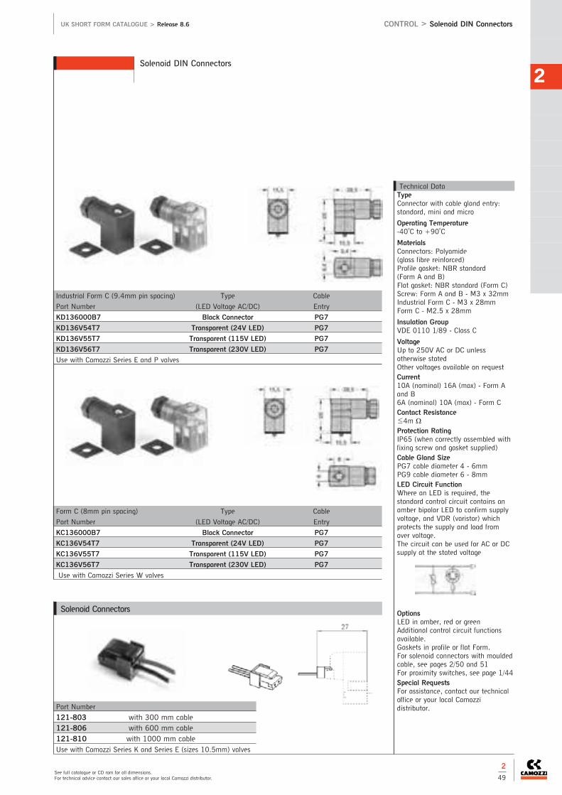
2
See full catalogue or CD rom for all dimensions.For technical advice contact our sales office or your local Camozzi distributor.
UK SHORT FORM CATALOGUE > Release 8.6 CONTROL > Solenoid DIN Connectors
Solenoid DIN Connectors
Form C (8mm pin spacing) Type Cable
Part Number (LED Voltage AC/DC) Entry
KC136000B7 Black Connector PG7
KC136V54T7 Transparent (24V LED) PG7
KC136V55T7 Transparent (115V LED) PG7
KC136V56T7 Transparent (230V LED) PG7
Use with Camozzi Series W valves
Industrial Form C (9.4mm pin spacing) Type Cable
Part Number (LED Voltage AC/DC) Entry
KD136000B7 Black Connector PG7
KD136V54T7 Transparent (24V LED) PG7
KD136V55T7 Transparent (115V LED) PG7
KD136V56T7 Transparent (230V LED) PG7
Use with Camozzi Series E and P valves
Technical DataTypeConnector with cable gland entry:standard, mini and micro
Operating Temperature-40oC to +90oC
MaterialsConnectors: Polyamide (glass fibre reinforced)Profile gasket: NBR standard (Form A and B)Flat gasket: NBR standard (Form C)Screw: Form A and B - M3 x 32mmIndustrial Form C - M3 x 28mmForm C - M2.5 x 28mm
Insulation GroupVDE 0110 1/89 - Class C
VoltageUp to 250V AC or DC unlessotherwise statedOther voltages available on requestCurrent10A (nominal) 16A (max) - Form Aand B6A (nominal) 10A (max) - Form CContact Resistance≤4m AProtection RatingIP65 (when correctly assembled withfixing screw and gasket supplied)Cable Gland SizePG7 cable diameter 4 - 6mmPG9 cable diameter 6 - 8mmLED Circuit FunctionWhere an LED is required, thestandard control circuit contains anamber bipolar LED to confirm supplyvoltage, and VDR (varistor) whichprotects the supply and load fromover voltage.The circuit can be used for AC or DCsupply at the stated voltage
OptionsLED in amber, red or greenAdditional control circuit functionsavailable.Gaskets in profile or flat Form.For solenoid connectors with mouldedcable, see pages 2/50 and 51For proximity switches, see page 1/44Special RequestsFor assistance, contact our technicaloffice or your local Camozzidistributor. Part Number
121-803 with 300 mm cable121-806 with 600 mm cable121-810 with 1000 mm cableUse with Camozzi Series K and Series E (sizes 10.5mm) valves
Solenoid Connectors
2
49

Moulded cable assemblies EN175301-803 (Formerly DIN43650)
The Camozzi range of DIN moulded cable connectors offers a fast and efficient method of connection, resulting in reducedinstallation time and cost.
Solenoid DIN Connectors - with Moulded Cable
CONTR
OL
2
The company reserves the right to vary models and dimensions without notice.Products designed for industrial applications. General terms and conditions for sale are available on www.camozzi.co.uk
CONTROL > Solenoid DIN Connectors UK SHORT FORM CATALOGUE > Release 8.6
Form A (18mm pin spacing) Double Earth Type Cable
Part Number (LED Voltage AC/DC) Length
MA134000PA05100 Cable Connector only 1M
MA134000PA05300 Cable Connector only 3M
MA634V54PA05100 Cable Connector (24V LED) 1M
MA634V54PA05300 Cable Connector (24V LED) 3M
MA634V55PA05100 Cable Connector (115V LED) 1M
MA634V55PA05300 Cable Connector (115V LED) 3M
MA634V56PA05100 Cable Connector (230V LED) 1M
MA634V56PA05300 Cable Connector (230V LED) 3M
Use with Camozzi Series 4 valves - 1/2, series 6 and A80 coils
Industrial Form B (11mm pin spacing) 12 O’Clock Earth Type Cable
Part Number (LED Voltage AC/DC) Length
MB135000PA05100 Cable Connector only 1M
MB135000PA05300 Cable Connector only 3M
MB635V54PA05100 Cable Connector (24V LED) 1M
MB635V54PA05300 Cable Connector (24V LED) 3M
MB635V55PA05100 Cable Connector (115V LED) 1M
MB635V55PA05300 Cable Connector (115V LED) 3M
MB635V56PA05100 Cable Connector (230V LED) 1M
MB635V56PA05300 Cable Connector (230V LED) 3M
Use with Camozzi Series A, series AP, series 3, series 4 and ISO valves
Technical DataTypeMoulded cable connectors: Standard,mini and micro
Operating Temperature-40oC to +90oC
MaterialsConnectors: TPUCable: PVC standard Integrated gasket: TPUScrew: Form A and B - M3 x 28mmIndustrial Form C M3 x 23mmForm C M2.5 x 23mm
Insulation GroupVDE 0110 1/89 - Class C
VoltageUp to 250V AC or DC unlessotherwise stated Other voltagesavailable on requestCurrent5A - Form A and B3A - Form CContact Resistance≤4m AProtection RatingIP67Standard Cable3 x 0.75mm2 conductors PVC HO5VVF (Form A and B)3 x 0.50mm2 conductors PVC HO3VVF (Form C)LED Circuit FunctionWhere an LED is required, thestandard control circuit contains anamber bipolar LED to confirm supplyvoltage, and VDR (varistor) whichprotects the supply and load fromover voltage.The circuit can be used for AC or DCsupply at the stated voltage.
OptionsAdditional cable types and lengths.LED in amber, red or green.Additional control circuit functionsavailable.For solenoid connectors with cablegland entry, pages 2/48 and 49.For proximity switches, see page 1/44Special RequestsFor assistance, contact our technicaloffice or your local Camozzidistributor.
2
50

2
See full catalogue or CD rom for all dimensions.For technical advice contact our sales office or your local Camozzi distributor.
UK SHORT FORM CATALOGUE > Release 8.6 CONTROL > Solenoid DIN Connectors
Solenoid DIN Connectors - with moulded cables
Industrial Form C (8mm pin spacing) Double Earth Type Cable
Part Number (LED Voltage AC/DC) Length
MC134000PA01100 Cable Connector only 1M
MC134000PA01300 Cable Connector only 3M
MC634V54TA01100 Cable Connector (24V LED) 1M
MC634V54TA01300 Cable Connector (24V LED) 3M
MC634V55TA01100 Cable Connector (115V LED) 1M
MC634V55TA01300 Cable Connector (115V LED) 3M
MC634V56TA01100 Cable Connector (230V LED) 1M
MC634V56TA01300 Cable Connector (230V LED) 3M
Use with Camozzi Series W valves
Industrial Form C (9.4mm pin spacing) Double Earth Type Cable
Part Number (LED Voltage AC/DC) Length
MD134000PA01100 Cable Connector only 1M
MD134000PA01300 Cable Connector only 3M
MD634V54TA01100 Cable Connector (24V LED) 1M
MD634V54TA01300 Cable Connector (24V LED) 3M
MD634V55TA01100 Cable Connector (115V LED) 1M
MD634V55TA01300 Cable Connector (115V LED) 3M
MD634V56TA01100 Cable Connector (230V LED) 1M
MD634V56TA01300 Cable Connector (230V LED) 3M
Use with Camozzi Series E, and Series P valves
Industrial Form B (11mm pin spacing) 6 O’Clock Earth Type Cable
Part Number (LED Voltage AC/DC) Length
MB136000PA05100 Cable Connector only 1M
MB136000PA05300 Cable Connector only 3M
MB636V54PA05100 Cable Connector (24V LED) 1M
MB636V54PA05300 Cable Connector (24V LED) 3M
MB636V55PA05100 Cable Connector (115V LED) 1M
MB636V55PA05300 Cable Connector (115V LED) 3M
MB636V56PA05100 Cable Connector (230V LED) 1M
MB636V56PA05300 Cable Connector (230V LED) 3M
Use with Camozzi Series A, series AP, Series 3, Series 4 and ISO valves and NAMUR Valves
Technical DataTypeMoulded cable connectors: Standard,mini and micro
Operating Temperature-40oC to +90oC.
MaterialsConnectors: TPUCable: PVC standard Integrated gasket: TPUScrew: Forms A and B - M3 x 28mmIndustrial Form C M3 x 23mmForm C M2.5 x 23mm
Insulation GroupVDE 0110 1/89 - Class C
VoltageUp to 250V AC or DC unlessotherwise stated Other voltagesavailable on requestCurrent5A - Form A and B3A - Form CContact Resistance≤4m AProtection RatingIP67Standard Cable3 x 0.75mm2 conductors PVC HO5VVF (Form A and B)3 x 0.50mm2 conductors PVC HO3VVF (Form C)LED Circuit FunctionWhere an LED is required, thestandard control circuit contains anamber bipolar LED to confirm supplyvoltage, and VDR (varistor) whichprotects the supply and load fromover voltage.The circuit can be used for AC or DCsupply at the stated voltage.
OptionsAdditional cable types and lengths.LED in amber, red or green.Additional control circuit functionsavailable. For solenoid connectors with cablegland entry, pages 2/48 and 49.For proximity switches, see page 1/44Special RequestsFor assistance, contact our technicaloffice or your local Camozzidistributor.
2
51

Plug-In for electro-pneumatically operated valves Series 3 1/8, 3/2, 5/2, and 5/3 way
Series 3 Valve Island Plug-In
CONTR
OL
2
The company reserves the right to vary models and dimensions without notice.Products designed for industrial applications. General terms and conditions for sale are available on www.camozzi.co.uk
CONTROL > Series 3 Valve Island Plug-In UK SHORT FORM CATALOGUE > Release 8.6
2
52
CODING EXAMPLE
SERIES:Series 3 PLUG-IN
CONNECTION: 8 = 1/8
3P 8 - E AB - 3B3M - U 7 7
3P
8
E
7
7
CONFIGURATION OFPNEUMATIC AND ELECTRICMODULES see table page 2/53
VALVE COMPOSITION see table page 2/53
SOLENOID DIMENSIONS7 = 22 x 22
SOLENOID VOLTAGE7 = 24 V DC
N° VALVE POSITIONSsee table page 2/53
SOLENOID MATERIALG= NylonU= PET
SPECIAL= standard
S = special to be specified
AB
3B3M
G
Technical DataConstructionSpool typeValve groupWays / Pos. 5/2 - 5/3 C.C. C.O. C.P.- 2x3/2 N.O. - 2x3/2 N.C. - 1 3/2N.O.+1 3/2 N.C.MaterialsAluminium body, stainless steelspool, seals in NBRMountingThrough holes in the valve bodyConnection1/8InstallationIn any positionOperating temperature0 to 60OC (with dry air at -20OC)Nominal flowRate*Qn 700 Nl/minNominal diameter7 mmFluidFiltered air, without lubrication. Iflubricated air is used, it isrecommended to use ISO VG32 oil,and to never interrupt the lubrication.SignallingLEDVoltage24 V DCVoltage tolerances+/- 10%Duty cycleED 100%Class of insulationClass HProtection classIP 65Power consumption3WPower supply ConnectorSUB-D 25 poles IP65

2
See full catalogue or CD rom for all dimensions.For technical advice contact our sales office or your local Camozzi distributor.
UK SHORT FORM CATALOGUE > Release 8.6 CONTROL > Series 3 Valve Island Plug-In
Table for the configuration of the modularity of the series 3 plug-in
2
53
A = 2 pos. [2] - 2 A A-A(2) 2 - A A-B
B = 3 pos. [3] - 3 B A-A(3) 3 - B A-B
C = 4 pos. [2] [2] - 4 C A-A(2) (2) 4 - C A-B[3] [2] - 5 D A-A
D = 5 pos. (3) (2) 5 - D A-B[2] [3] - 5 D A-C(2) (3) 5 - D A-D[3] [3] - 6 E A-A
E = 6 pos. (3) (3) 6 - E A-B[2] [2] [2] - 6 E B-A(2) (2) (2) 6 - E B-B[2] [3] [2] - 7 F A-A(2) (3) (2) 7 - F A-B
F = 7 pos. [2] [2] [3] - 7 F B-A(2) (2) (3) 7 - F B-B[3] [2] [2] - 7 F B-C(3) (2) (2) 7 - F B-D[3] [3] [2] - 8 G A-A
G = 8 pos. (3) (3) (2) 8 - G A-B[2] [3] [3] - 8 G A-C(2) (3) (3) 8 - G A-D
[2] [2] [2] [2] - 8 G B-A(2) (2) (2) (2) 8 - G B-B[3] [2] [3] - 8 G B-C(3) (2) (3) 8 - G B-D
H = 9 pos. [3] [3] [3] - 9 H A-A(3) (3) (3) 9 - H A-B
[3] [2] [2] [2] - 9 H B-A(3) (2) (2) (2) 9 - H B-B[2] [3] [2] [2] - 9 H B-C(2) (3) (2) (2) 9 - H B-D[2] [2] [3] [2] - 9 H B-E(2) (2) (3) (2) 9 - H B-F[2] [2] [2] [3] - 9 H B-G(2) (2) (2) (3) 9 - H B-H
I = 10 pos. [2] [3] [3] [2] - 10 I A-A(2) (3) (3) (2) 10 - I A-B[2] [3] [3] [3] - 11 J A-A
J = 11 pos. (2) (3) (3) (3) 11 - J A-B[3] [3] [3] [2] - 11 J A-C(3) (3) (3) (2) 11 - J A-D(3) [3] [3] [3] 3 9 K A-A
K = 12 pos. (3) (3) [3] [3] 6 6 K A-B(3) (3) (3) [3] 9 3 K A-C
(2) [3] [3] [3] [2] 2 11 L A-AL = 13 pos. (2) (3) [3] [3] [2] 5 8 L A-B
(2) (3) (3) [3] [2] 8 5 L A-C(2) (3) (3) (3) [2] 11 2 L A-D(2) (3) [3] [3] [3] 5 9 M A-A(2) (3) (3) [3] [3] 8 6 M A-B
M = 14 pos. (2) (3) (3) (3) [3] 11 3 M A-C(3) [3] [3] [3] [2] 3 11 M A-D(3) (3) [3] [3] [2] 6 8 M A-E(3) (3) (3) [3] [2] 9 5 M A-F
N = 15 pos. (3) (3) [3] [3] [3] 6 9 N A-A(3) (3) (3) [3] [3] 9 6 N A-B
(2) (3) [3] [3] [3] [2] 5 11 O A-AO = 16 pos. (2) (3) (3) [3] [3] [2] 8 8 O A-B
(2) (3) (3) (3) [3] [2] 11 5 O A-C(2) (3) (3) [3] [3] [3] 8 9 P A-A
P = 17 pos. (2) (3) (3) (3) [3] [3] 11 6 P A-B(3) (3) [3] [3] [3] [2] 6 11 P A-C(3) (3) (3) [3] [3] [2] 9 8 P A-D
Q = 18 pos. (3) (3) (3) [3] [3] [3] 9 9 Q A-AR = 19 pos. (2) (3) (3) [3] [3] [3] [2] 8 11 R A-A
(2) (3) (3) (3) [3] [3] [2] 11 8 R A-BS = 20 pos. (2) (3) (3) (3) [3] [3] [3] 11 9 S A-A
(3) (3) (3) [3] [3] [3] [2] 9 11 S A-BT = 21 pos.* (3) (3) [3] [3] [3] [3] [3] 10 11 T A-A
(3) (3) (3) [3] [3] [3] [3] 11 10 T A-BU = 22 pos. (2) (3) (3) (3) [3] [3] [3] [2] 11 11 U A-A
The letter Number of valve positions, showing the Position of the D-SUB and the number Configuration coderepresents the number combination of the modules from which of valves to which it is connected
of valve positions the valve island is built positions configurationRIGHTLEFT
*On the valve island with 21 valve positions, electric and pneumatic modularity do not correspond

CONTR
OL
2
The company reserves the right to vary models and dimensions without notice.Products designed for industrial applications. General terms and conditions for sale are available on www.camozzi.co.uk
CONTROL > Series 3 Valve Island Plug-In UK SHORT FORM CATALOGUE > Release 8.6
2
54
Mod. Function Actuation Pilot supply Working pressure (bar) Pilot pressure (bar) Code338D-015-02 2 x 3/2 NC solenoid/spring Internal 2,5 - 10 - C348D-015-02 2 x 3/2 NO solenoid/spring Internal 2.5 - 10 - A398D-015-02 1 3/2 NC + 1 3/2 NO solenoid/spring Internal 2.5 - 10 - G358-015-02 5/2 monostable solenoid/spring Internal 2.5 - 10 - M358-011-02 5/2 bistable solenoid/solenoid Internal 1.5 - 10 - B368-011-02 5/3 CC solenoid/solenoid Internal 2 - 10 - H378-011-02 5/3 CO solenoid/solenoid Internal 2 - 10 - K388-011-02 5/3 CP solenoid/solenoid Internal 2 - 10 - N338D-E15-02 2 x 3/2 NC solenoid/spring External -0.9 - 10 2.5 - 10 Q348D-E15-02 2 x 3/2 NO solenoid/spring External -0.9 - 10 2.5 - 10 R398D-E15-02 1 3/2 NC + 1 3/2 NO solenoid/spring External -0.9 - 10 2.5 - 10 S358-E15-02 5/2 monostable solenoid/spring External -0.9 - 10 2.5 - 10 D358-E11-02 5/2 bistable solenoid/solenoid External -0.9 - 10 1.5 - 10 Y368-E11-02 5/3 CC solenoid/solenoid External -0.9 - 10 2 - 10 V378-E11-02 5/3 CO solenoid/solenoid External -0.9 - 10 2 - 10 Z388-E11-02 5/3 CP solenoid/solenoid External -0.9 - 10 2 - 10 WCNVL/1L free position (electrical and pneumatic cover) - - - - LCNVL-3P1 plate for supply and outlets - - - - XCNVL-3H-TP (x1) diaphragm for supply (1) - - - - UCNVL-3H-TP (x2) diaphragm for outlets (3-5) - - - - JCNVL-3H-TP (x3) diaphragm for supply (1) and outlets (3-5) - - - - T
Series 3 Plug-In Functioning of Solenoid Valves

2
See full catalogue or CD rom for all dimensions.For technical advice contact our sales office or your local Camozzi distributor.
UK SHORT FORM CATALOGUE > Release 8.6 CONTROL > Series 3 Valve Island Plug-In
Electrical Modules
2
55
Part Number
3PAC-R-RI2
Part Number
3PAC-R-LI2
To be mounted withmanifold CNVL-3H2
To be mounted withmanifold CNVL-3H2
Part Number
3PAC-R-RS2
Part Number
3PAC-R-LS2
To be mounted withmanifold CNVL-3H2
To be mounted withmanifold CNVL-3H2
Part Number
3PAC-R-RS3
Part Number
3PAC-R-LS3
To be mounted withmanifold CNVL-3H3
To be mounted withmanifold CNVL-3H3

CONTR
OL
2
The company reserves the right to vary models and dimensions without notice.Products designed for industrial applications. General terms and conditions for sale are available on www.camozzi.co.uk
CONTROL > Series 3 Valve Island Plug-In UK SHORT FORM CATALOGUE > Release 8.6
Electrical Modules
2
56
For valves withtwo solenoids
End cap for electricmodule
Part Number
3PAC-R-TP1
Part Number
3PAC-R-IF1
Part Number
3PAC-R-RI3
Part Number
3PAC-R-LI3
To be mounted withmanifold CNVL-3I3
To be mounted withmanifold CNVL-3I3

Basic Module with Two Positions
CNVL-3H2 to suit series 3, 1/8
CNVL-4H2 to suit series 3, 1/4
The packaging contains the following items: 3 O-rings, 2 Fixing
Screws and 2 Junction plugs per station.
Basic Module with Three Positions
CNVL-3H3 to suit series 3, 1/8
CNVL-4H3 to suit series 3, 1/4
The packaging contains the following items: 3 O-rings, 2 Fixing Screws
and 2 Junction plugs per station.
G3/8
Expansion Module with Two Positions
CNVL-3I2 to suit series 3, 1/8
CNVL-4I2 to suit series 3, 1/4
The packaging contains the following items: 3 O-rings, 2 Fixing
Screws and 2 Junction plugs.
Expansion Module with Three Positions
CNVL-3I3 to suit series 3, 1/8
CNVL-4I3 to suit series 3, 1/4
The packaging contains the following items: 3 O-rings, 2 Fixing Screws
and 2 Junction plugs.
G3/8
2
See full catalogue or CD rom for all dimensions.For technical advice contact our sales office or your local Camozzi distributor.
UK SHORT FORM CATALOGUE > Release 8.6 CONTROL > Series 3 Valve Island Plug-In
Modular Manifolds for Series 3, 1/8 and 1/4
2
57
Excluder
CNVL/1L Code L
The packaging contains the following items: 3
O-rings and 2 Fixing Screws
Part Number
CNVL/3P1
Part Number
CNVL-3H-TP
CNVL-4H-TP
Code for Plug-in Versions
T Supply (1) + exhaust (3 and 5)
U Supply (1)
J Exhausts (3 and 5)

CONTR
OL
2
The company reserves the right to vary models and dimensions without notice.Products designed for industrial applications. General terms and conditions for sale are available on www.camozzi.co.uk
CONTROL > Series UK SHORT FORM CATALOGUE > Release 8.6
2
58
Fieldbus system combined with electro-pneumatically operated valves Series 3 ports G1/8Interface with: Profibus-DP, CANopen, DeviceNetValve functions: 2x3/2, 5/2 and 5/3 way CO CC CPConforms with standards EN-61326-1 and EN-61010-1
Series 3 Valve Island Fieldbus
CONTROL > Series 3 Valve Island Fieldbus
Technical DataConstructionSpool typeValve Functions5/2 - 5/3 C.C. C.O. C.P. - 2x3/2 N.O.- 2x3/2 N.C. - 1 3/2 N.O.+1 3/2N.C.MaterialsAluminium body, stainless steelspool, seals in NBR, technopolymerConnectionValve = 1/8 - Manifold = 3/8MountingThrough holes in the valve bodyOperating Temperature0 to 50OCNominal Flow RateQn 700 Nl/minFieldBus Protocol3F8: Profibus-DP - 3R8: DeviceNet -3G8: CANopenFieldBus Signalling Led3F8: 1 led green RUN, 1 led redDIA, 1 led red BF3R8: 1 led green IO, 1 led red NS, 1led red MS3G8: 1 led green RUN, 1 led redDIA, 1 led red BFValve Signalling LedLED (yellow)Logical Supply Voltage24 V DC (-15% / +20% with noconnected inputs, or consider theconnected inputs supply range)Power Supply Voltage24 V DC (for the tolerance, considerthe total loads of the connectedinputs)Duty CycleED 100%Maximum Number of Nodes3F8: 32/127 - 3R8: 64 - 3G8: 127Maximum Baud Rate3F8: 12 Mbit/sec - 3R8: 500Kbit/sec - 3G8: 1 Mbit/sec
CODING EXAMPLE
CONNECTION:3F = Profibus-DP3R = DeviceNet3G = CANopen
3F 8 - 2A - BC - EBB - BCT2M2B - U77
3F
8
2A
U77
VALVE COMPOSITION see table page 2/59
SOLENOID TYPEMaterial Dimension VoltageG= PA 7= 22x22 7=24V DCU= PET
BC
EBB
BCT2M2B
ELECTRIC OUTPUTSMODULES 0 = no moduleB = 4 outputs M12 duoC = 8 outputs SUB-D 37pinD = 16 outputs SUB-D 37pinE = 24 outputs SUB-D 37pinF = 32 outputs SUB-D 37pin
VALVES FUNCTIONSsee table page 2/59
VERSIONS= standard
S = special (to be specified)
ELECTRIC INPUTS MODULES0= no moduleA= module 8 input M8
SOLENOID VALES CONNECTIONS: 8 = 1/8

2
See full catalogue or CD rom for all dimensions.For technical advice contact our sales office or your local Camozzi distributor.
UK SHORT FORM CATALOGUE > Release 8.6 CONTROL > Series 3 Valve Island Fieldbus
2
59
Table for the configuration of valve island series 3 fieldbus
The valve island code is always read from left to right, the electrical module is positioned on top of the pneumatic manifold, as on the photo on page 2/58. It is also possible to create 2 or more pressure/exhaust zones in the valve island by inserting the diaphragm Mod. CNVL-TP between the modules.
A = 2 pos. (2) A A-BB = 3 pos. (3) B A-BC = 4 pos. (2) (2) C A - B
D = 5 pos. (3) (2) D A-B(2) (3) D A-D
E = 6 pos. (3) (3) E A-B(2) (2) (2) E B-B(2) (3) (2) F A-B
F = 7 pos. (2) (2) (3) F B-B(3) (2) (2) F B-D(3) (3) (2) G A-B
G = 8 pos. (2) (3) (3) G A-D(2) (2) (2) (2) G B-B(3) (2) (3) G B-D(3) (3) (3) H A-B
(3) (2) (2) (2) H B-BH = 9 pos. (2) (3) (2)(2) H B-D
(2) (2) (3) (2) H B-F(2) (2) (2) (3) H B-H
The letter Number of valve positions, showing the Configuration code Configuration coderepresents the number combination of the modules from which n° of positions of the sub-base
of valve positions the valve island is built
Series 3 Functioning of Solenoid Valves
Mod. Function Actuation Pilot supply Working pressure (bar) Pilot pressure (bar) Code338D-015-02 2 x 3/2 NC solenoid/spring Internal 2.5 - 10 - C348D-015-02 2 x 3/2 NO solenoid/spring Internal 2.5 - 10 - A398D-015-02 1 3/2 NC + 1 3/2 NO solenoid/spring Internal 2.5 - 10 - G358-015-02 5/2 monostable solenoid/spring Internal 2.5 - 10 - M358-011-02 5/2 bistable solenoid/solenoid Internal 1.5 - 10 - B368-011-02 5/3 CC solenoid/solenoid Internal 2 - 10 - H378-011-02 5/3 CO solenoid/solenoid Internal 2 - 10 - K388-011-02 5/3 CP solenoid/solenoid Internal 2 - 10 - N338D-E15-02 2 x 3/2 NC solenoid/spring External -0.9 - 10 2.5 - 10 Q348D-E15-02 2 x 3/2 NO solenoid/spring External -0.9 - 10 2.5 - 10 R398D-E15-02 1 3/2 NC + 1 3/2 NO solenoid/spring External -0.9 - 10 2.5 - 10 S358-E15-02 5/2 monostable solenoid/spring External -0.9 - 10 2.5 - 10 D358-E11-02 5/2 bistable solenoid/solenoid External -0.9 - 10 1.5 - 10 Y368-E11-02 5/3 CC solenoid/solenoid External -0.9 - 10 2 - 10 V378-E11-02 5/3 CO solenoid/solenoid External -0.9 - 10 2 - 10 Z388-E11-02 5/3 CP solenoid/solenoid External -0.9 - 10 2 - 10 WCNVL/1L free position (electrical and pneumatic cover) - - - - LCNVL-3P1 plate for supply and outlets - - - - XCNVL-3H-TP (x1) diaphragm for supply (1) - - - - UCNVL-3H-TP (x2) diaphragm for outlets (3-5) - - - - JCNVL-3H-TP (x3) diaphragm for supply (1) and outlets (3-5) - - - - T

CONTR
OL
2
The company reserves the right to vary models and dimensions without notice.Products designed for industrial applications. General terms and conditions for sale are available on www.camozzi.co.uk
CONTROL > Series 3 Valve Island Fieldbus UK SHORT FORM CATALOGUE > Release 8.6
Valve Island - characteristics
2
60
Bus-In Bus-Out system for connection to the Fieldbus network. Double electrical supplies (1 for control and 1 for power).Addressing of every node via rotary switches. Leds indicating the working state. Handling of a max n° of 64 inputs and 64outputs (I/O). Electric outputs mod. on the right side of the node are available with connection M12 duo and/or Sub-D a37 poles and connected to pneumatic sub-bases (max 9 pos. mono/bistable valves). It’s possible to pilot other multipoleisland valves and/or systems, managed through digital signals, using connection cables 37/25 pin. Similarly, on the leftside of the node it’s possible to connect Input Mod. 8 (8 connections M8 every Mod.). All Mod. I/O can be easily insertedthanks to their direct connection to the plate. Manuals and configuration files are available on our website:www.camozzi.com in the Section Products/Download.
DRAWING LEGEND: 1 = digital inputs module 4 = digital outputs module connector 37 poles2 = Fieldbus module 5 = penumatic/electric interface module + foot3 = digital outputs module M12 connector

Pneumatic Part: Modules of 2, 4 and 8 valve positionsElectrical connections: Individual, multipole, or fieldbus connection.Profibus DP (CanOpen, DeviceNet and ASI under preparation)For further detail please see our full catalogue
Series Y Valve Island2
See full catalogue or CD rom for all dimensions.For technical advice contact our sales office or your local Camozzi distributor.
UK SHORT FORM CATALOGUE > Release 8.6 CONTROL > Series Y
Technical DataType of ConstructionSpool type
MediaFiltered air 5 micron or lower,without lubrication. If lubricated air isused, it is recommended to use oilISO VG32. Once applied thelubrication should never beinterrupted
Flow RatesSee technical data page 2/7
Operating PressureSee technical data page 2/7
Pilot PressureSee technical data page 2/7
Flow Rate800 Nl/min
Operating Temperature0oC to +50oC.
MaterialsSpool: AluminiumCartridge: brassSeals: NBR
ConnectionsOutlets 2 and 4 = 1/8Inlets 1 and 11 = 1/4Pilot connections 12/14 andrespective exhaust 82/84 = 1/8Outlets 3/5 = 1/2 in line connectionsSpecial RequestsFor assistance, contact our technicaloffice or your local Camozzidistributor.
Valve Island with individual connection
Valve Island with Multipole connection
Possibility of Multipole connection
The Multipole version is available in two sizes, with 4, 6 or 8 valve positions. These can be freely equipped witheither monostable or bistable valves.It is possible to join two or more valve islandssimply by removing one terminal plate from eachvalve island and replacing them with oneintermediate plate for supplementary inlets andexhaust Mod.XThe valve island can be composed of modules of2, 4, 6 or 8 valve positions joined together withthe channels 1/11 and 3/5, either separated fromeach other with seal type T (diaphragm) or joined together with seal type P(through).
Multipole connection
The electrical connection is made by means ofsingle connectors directly on each individual pilotvalve.The modules from which the valve island iscomposed can be of 2, 4, 6 or 8 valve positions,joined together with the channels 1/11 and 3/5either separated from each other with seal type T(diaphragm) or joined with seal type P (through). This solution has no limit to the number of valvepositions, even if it is advisable to insert anintermediate plate for supplementary inlets and exhaust after every 8positions.The manual override and the signalling LED arelocated on the pilot valves.
Individual connection
2
61

CONTR
OL
2
The company reserves the right to vary models and dimensions without notice.Products designed for industrial applications. General terms and conditions for sale are available on www.camozzi.co.uk
CONTROL > Series Y UK SHORT FORM CATALOGUE > Release 8.6
Fieldbus Connection
2
62
Initial module
Valve Island with Fieldbus connection(expansion module 8 positions for single assembly)
Valve Island with Fieldbus connection(expansion module 4 positions for single assembly)
Valve Island with Fieldbus connection(expansion module 2 positions for single assembly)
Valve Island with Fieldbus connection(expansion module 8 positions for combined assembly)
Valve Island with Fieldbus connection(expansion module 4 positions for combined assembly)
Valve Island with Fieldbus connection(expansion module 2 positions for combined assembly)
Possibility of Fieldbus connection
The initial module always has 8 positions. It is only the initial module to which the Fieldbus, (Profibus DP and other protocols) and electrical supply (24V DC) is connected. Each initial module can accommodate up to 32 coils distributed between the initial and the expansion modules.It recognises the position of the coils automatically assigning them anaddress, following a certain sequence. Through a serial interface (RS232), located on the main module it is possible to connect a PC or Palm Pilot to the valve island.Using a PC or an external Palm Pilot it is possible to:- set the address of the fieldbus node without using switches- manually set the internal addresses of the signals to the coils, changing theinitial address settings created.
- manually activate or deactivate each outlet individually, by passing themain program while it is active and running.
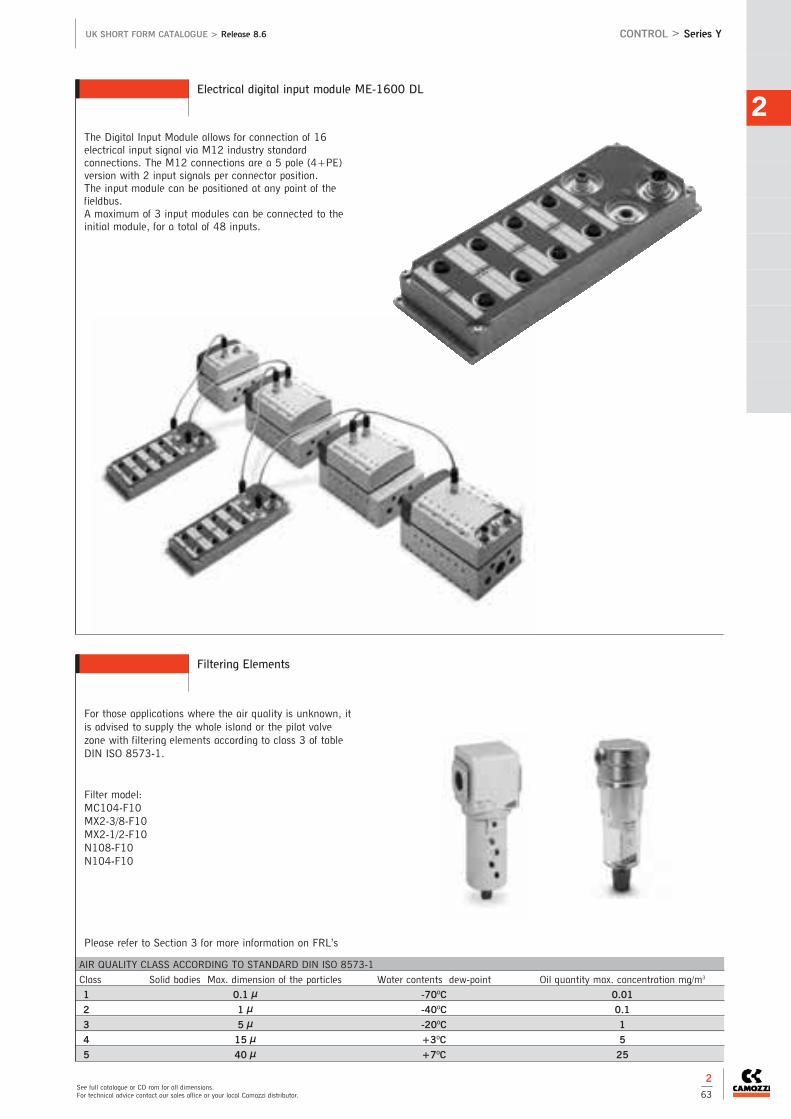
2
See full catalogue or CD rom for all dimensions.For technical advice contact our sales office or your local Camozzi distributor.
UK SHORT FORM CATALOGUE > Release 8.6 CONTROL > Series Y
Electrical digital input module ME-1600 DL
Filtering Elements
2
63
The Digital Input Module allows for connection of 16electrical input signal via M12 industry standardconnections. The M12 connections are a 5 pole (4+PE)version with 2 input signals per connector position. The input module can be positioned at any point of thefieldbus. A maximum of 3 input modules can be connected to theinitial module, for a total of 48 inputs.
For those applications where the air quality is unknown, itis advised to supply the whole island or the pilot valvezone with filtering elements according to class 3 of tableDIN ISO 8573-1.
Filter model:MC104-F10MX2-3/8-F10MX2-1/2-F10N108-F10N104-F10
Please refer to Section 3 for more information on FRL’s
AIR QUALITY CLASS ACCORDING TO STANDARD DIN ISO 8573-1
Class Solid bodies Max. dimension of the particles Water contents dew-point Oil quantity max. concentration mg/m3
1 0.1 µ -70OC 0.01
2 1 µ -40OC 0.1
3 5 µ -20OC 1
4 15 µ +3OC 5
5 40 µ +7OC 25
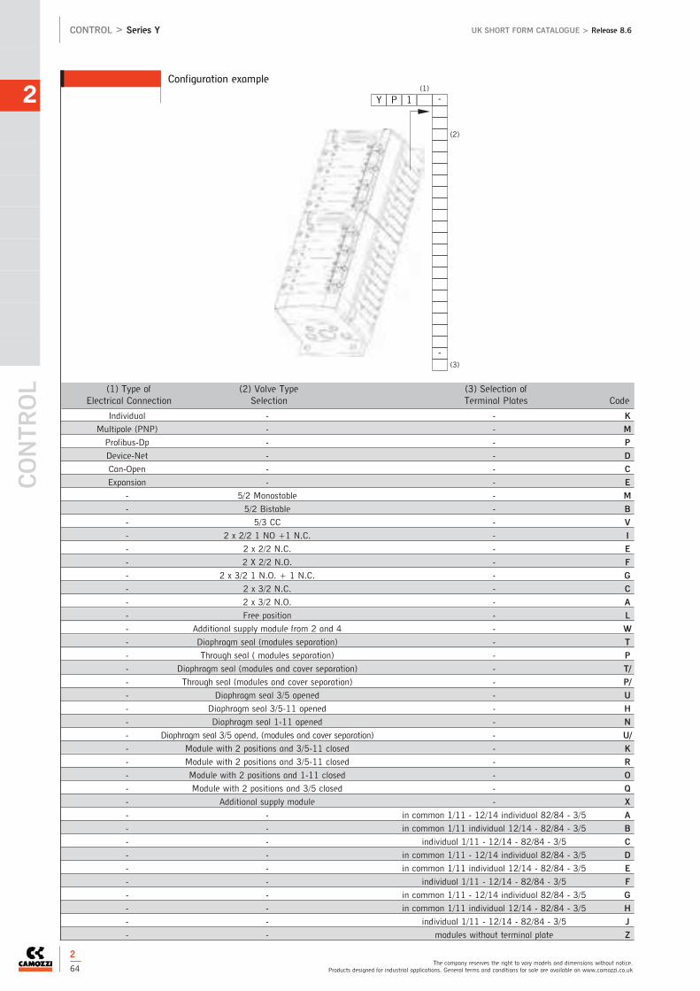
CONTR
OL
2
The company reserves the right to vary models and dimensions without notice.Products designed for industrial applications. General terms and conditions for sale are available on www.camozzi.co.uk
CONTROL > Series Y UK SHORT FORM CATALOGUE > Release 8.6
Configuration example
2
64
(1) Type of (2) Valve Type (3) Selection ofElectrical Connection Selection Terminal Plates Code
Individual - - K
Multipole (PNP) - - M
Profibus-Dp - - P
Device-Net - - D
Can-Open - - C
Expansion - - E
- 5/2 Monostable - M
- 5/2 Bistable - B
- 5/3 CC - V
- 2 x 2/2 1 NO +1 N.C. - I
- 2 x 2/2 N.C. - E
- 2 X 2/2 N.O. - F
- 2 x 3/2 1 N.O. + 1 N.C. - G
- 2 x 3/2 N.C. - C
- 2 x 3/2 N.O. - A
- Free position - L
- Additional supply module from 2 and 4 - W
- Diaphragm seal (modules separation) - T
- Through seal ( modules separation) - P
- Diaphragm seal (modules and cover separation) - T/
- Through seal (modules and cover separation) - P/
- Diaphragm seal 3/5 opened - U
- Diaphragm seal 3/5-11 opened - H
- Diaphragm seal 1-11 opened - N
- Diaphragm seal 3/5 opend, (modules and cover separation) - U/
- Module with 2 positions and 3/5-11 closed - K
- Module with 2 positions and 3/5-11 closed - R
- Module with 2 positions and 1-11 closed - O
- Module with 2 positions and 3/5 closed - Q
- Additional supply module - X
- - in common 1/11 - 12/14 individual 82/84 - 3/5 A
- - in common 1/11 individual 12/14 - 82/84 - 3/5 B
- - individual 1/11 - 12/14 - 82/84 - 3/5 C
- - in common 1/11 - 12/14 individual 82/84 - 3/5 D
- - in common 1/11 individual 12/14 - 82/84 - 3/5 E
- - individual 1/11 - 12/14 - 82/84 - 3/5 F
- - in common 1/11 - 12/14 individual 82/84 - 3/5 G
- - in common 1/11 individual 12/14 - 82/84 - 3/5 H
- - individual 1/11 - 12/14 - 82/84 - 3/5 J
- - modules without terminal plate Z
(1)
Y 1 -P
(2)
(3)
-

Valve Island with Pneumatics and Electronics integratedAvailable versions: Multipole (PNP and NPN) and Fieldbus (Profibus-DP, DeviceNet, CANopen) Valve functions: 2x2/2; 2x3/2; 5/2; 5/3 CC
Series H Valve Island 2
See full catalogue or CD rom for all dimensions.For technical advice contact our sales office or your local Camozzi distributor.
UK SHORT FORM CATALOGUE > Release 8.6 CONTROL > Series H
2
65
Series H Valve Island - Multipole and Expandable Fieldbus
Fieldbus Expansion (local fieldbus) version
The Expansion islands can handle electrical andpneumatic outlets up to a 50 m distance from theIsland that interfaces directly to theFieldbus net.These expansions communicate with the expandablefieldbus unit (above) through a local fieldbus(Cam.I.Net) and are connected through pre-wiredcables (9 poles) of different lengths.
Individual Fieldbus version
The individual fieldbus version consists of an islandthat enables the handling of 64 Inputs and 64Outputs. It does not enable the handling of the Expansions butit can be equipped with all peripheral elements of theexpandable versions.The whole electronic system can be used in othertypes of Valve islands.
Series H Valve Island - Expansion and Individual Fieldbus
Multipole version
In this configuration Series H can be connectedrapidly and safely thanks to the multipole connectionwith wired cable of sizes of 3 & 5 m (standard).
Expandable Fieldbus version
This version enables a direct interface to fieldbussystems such as: Profibus-DP, DeviceNet andCANopen.The various types of electical and pneumaticelements that can be connected, and the possibilityto decentralise the expansion Islands gives this modelextreme flexibility.
Technical DataPNEUMATIC SECTIONConstructionspool with sealsValve Functions5/2 monostable and bistable5/3 C.C. 2 x 2/2 N.O.2 x 2/2 N.C. 1 x 2/2 N.C.+ 1 x N.O.2 x 3/2 N.C. 2 x 3/2 N.O.1 x 3/2 N.C.+ 1 x 3/2 N.O.MaterialsAluminium spool and HNBR seals,brass cartridges,technopolymer bodyand end covers, aluminium subbaseother NBR sealsConnectionInlets 2 and 4, size 1 = M7 or tubeØ4 or tube Ø6Inlets 2 and 4, size 2 = 1/8 or tubeØ6 or tube Ø8Supply, size 1 = 1/4 or tube Ø8Supply, size 2 = 1/4 or tube Ø10Pilot, size 1 and 2= M7Exhausts 3 and 5, size 1 and 2 =1/4 or with silencerExhausts 82 and 84, size 1 and 2 =M7 or with silencerTemperature0 to 50OCMediaFiltered air class 5.4.4 according toISO 8573.1If lubrication is necessary use only oilwith maximum viscosity 32 Cst.Dimensions/Sizes10.5 mm, 21 mmFlow RatesSee technical data page 2/7
Operating PressureSee technical data page 2/7
Pilot PressureSee technical data page 2/7Mounting PositionAny positionINPUTS SECTIONVoltage24 V DC +/- 10% (directly supplied by the Valve Island)Power Consumptiion10 mAWorking Temperature0 to 50OCProtection Against overload (400 mA every 4 sensors)Protection ClassIP 65Max. NO of connection inputs64Max. NO connection inputs Modules8ELECTRIC SECTIONVoltage24 V DC +/- 10% (directly supplied by the Valve Island)Power Consumptiion0.5 W per coil Duty CycleED 100%Protection ClassIP65Max. NO of coils multipole32Max. NO of coils - fieldbus64

CONTR
OL
2
The company reserves the right to vary models and dimensions without notice.Products designed for industrial applications. General terms and conditions for sale are available on www.camozzi.co.uk
CONTROL > Series H UK SHORT FORM CATALOGUE > Release 8.6
Coding example - Multipole version
2
66
(2) ELECTRICAL CONNECTION
Multipole 25 pin PNP MMultipole 25 pin NPN NMultipole 37 pin PNP HMultipole 37 pin NPN L
(3) CABLE LENGTH
03 m 0305 m 0510 m 1015 m 1520 m 2025 m 2530 m 30Length to be defined in meters X
(4) SUB-BASES AND SEALS
Threaded M7 AFittings for tube Ø4 BFittings for tube Ø6 CChannel 1; 3; 5 closed - threaded M7 DChannel 1; 3; 5 closed - cartridge Ø4 EChannel 1; 3; 5 closed - cartridge Ø6 FChannel 3; 5 closed - threaded M7 GChannel 3; 5 closed - cartridge Ø4 HChannel 3; 5 closed - cartridge Ø6 IChannel 1 closed - threaded M7 LChannel 1 closed - cartridge Ø4 MChannel 1 closed - cartridge Ø6 NSub-base for valves size 2 Threaded G1/8 QFittings for tube Ø6 RFittings for tube Ø8 SSupplem. pressure and exhaustSupplem. pressure supply and exhaust XSupplem. pressure supply and exhaust with integrated silencer YSub-base for electrical supply
(6) TERMINAL PLATES
1; 12/14 in common 3/5; 82/84 threaded ports A1; 12/14 separate 3/5; 82/84 threaded ports B1; 12/14 in common 3/5; 82/84 with integrated silencer C1; 12/14 separate 3/5; 82/84 with integrated silencer DTerminal plates with cartridges Ø8 for size 11; 12/14 in common 3/5; 82/84 conveyable E1; 12/14 separate 3/5; 82/84 conveyable F1; 12/14 in common 3/5; 82/84 with integrated silencer G1; 12/14 separate 3/5; 82/84 with integrated silencer HTerminal plates with cartridges Ø10 for size 2 and 51; 12/14 in common 3/5; 82/84 conveyable I1; 12/14 separate 3/5; 82/84 conveyable L1; 12/14 in common 3/5; 82/84 with integrated silencer M1; 12/14 separate 3/5; 82/84 with integrated silencer N
(1) HP SIZE
10,5 121 2Mixed (10.5 + 21) 5
(5) SOLENOID VALVE
5/2 Monostable M5/2 Bistable B5/3 CC V2 x 3/2 NC C2 x 3/2 NO A1 x 3/2 NC + 1 x 3/2 NO G2 x 2/2 NC E2 x 2/2 NO F1 x 2/2 NC + 1 x 2/2 NO IFree position LValves with integr. pressure reg. online 1 (size only)5/2 Monostable N5/2 Bistable P5/3 CC Q2 x 3/2 NC R2 x 3/2 NO S1 x 3/2 NC + 1 x 3/2 NO T2 x 2/2 NC U2 x 2/2 NO X1 x 2/2 NC + 1 x 2/2 NO Y
(4) SUB-BASES AND SEALS
Module for electrical power supply separ. + suppl. inlet press. KSealsDiaphr. seal - channel 1; 3; 5 TDiaphr. seal - channel 1 UDiaphr. seal - channel 3; 5 V

2
See full catalogue or CD rom for all dimensions.For technical advice contact our sales office or your local Camozzi distributor.
UK SHORT FORM CATALOGUE > Release 8.6 CONTROL > Series H
2
67
(2) ELECTRICAL CONNECTOR
Profibus-DP (expandable) PCANopen (expandable) CDeviceNet (expandable) DOnly for P-C-D expansion E
(3) INPUT MODULES
Without inputs 0Input modue - 8 digital (8xM8) A
(4) OUTPUT MODULES
(7) TERMINAL PLATES
1; 12/14 in common 3/5; 82/84 threaded ports A1; 12/14 separate 3/5; 82/84 threaded ports B1; 12/14 in common 3/5; 82/84 with integrated silencer C1; 12/14 separate 3/5; 82/84 with integrated silencer DTerminal plates with cartridges Ø8 for size 11; 12/14 in common 3/5; 82/84 conveyable E1; 12/14 separate 3/5; 82/84 conveyable F1; 12/14 in common 3/5; 82/84 with integrated silencer G1; 12/14 separate 3/5; 82/84 with integrated silencer HTerminal plates with cartridges Ø10 for size 2 and 51; 12/14 in common 3/5; 82/84 conveyable I1; 12/14 separate 3/5; 82/84 conveyable L1; 12/14 in common 3/5; 82/84 with integrated silencer M1; 12/14 separate 3/5; 82/84 with integrated silencer N
(1) HP PASSO
10,5 121 2Mixed (10,5 + 21) 5
(6) SOLENOID VALVE
5/2 Monostable M5/2 Bistable B5/3 CC V2 x 3/2 NC C2 x 3/2 NO A1 x 3/2 NC + 1 x 3/2 NO G2 x 3/2 NC E2 x 3/2 NO F1 x 2/2 NC + 1 x 2/2 NO IFree position LValves with integr. pressure reg. online 1 (size only)5/2 Monostable N5/2 Bistable P5/3 CC Q2 x 3/2 NC R2 x 3/2 NO S1 x 3/2 NC + 1 x 3/2 NO T2 x 2/2 NC U2 x 2/2 NO X1 x 2/2 NC + 1 x 2/2 NO Y
(5) SUB-BASES AND SEALS
Threaded M7 AFittings for tube Ø4 BFittings for tube Ø6 CChannel 1; 3; 5 closed - threaded M7 DChannel 1; 3; 5 closed - cartridge Ø4 EChannel 1; 3; 5 closed - cartridge Ø6 FChannel 3; 5 closed - threaded M7 GChannel 3; 5 closed - cartridge Ø4 HChannel 3; 5 closed - cartridge Ø6 IChannel 1 closed - threaded M7 LChannel 1 closed - cartridge Ø4 MChannel 1 closed - cartridge Ø6 NSub-base for valves size 2 Threaded G1/8 QFittings for tube Ø6 RFittings for tube Ø8 SSupplem. pressure and exhaust
(5) SUB-BASES AND SEALS
Supplem. pressure supply and exhaust XSupplem. pressure supply and exhaust with integrated silencer YSub-base for electrical supplyElectrical supply separ. + supply inlet pressure KSealsDiaphr. seal - channel 1; 3; 5 TDiaphr. seal - channel 1 UDiaphr. seal - channel 3; 5 V
Without inputs 0Right terminal+outputs(don’t use on vers. F) XRight terminal with el.supply+outputs (don’tuse on vers. F) Y4 outputs M12 duo B8 outputs SUB-D37 pin C16 outputs SUB-D37 pin D24 outputs SUB-D37 pin E
Coding example - Fieldbus version

CONTR
OL
2
The company reserves the right to vary models and dimensions without notice.Products designed for industrial applications. General terms and conditions for sale are available on www.camozzi.co.uk
CONTROL > Series H UK SHORT FORM CATALOGUE > Release 8.6
Coding example - Individual version
2
68
(4) OUTPUT MODULES
Without inputs 0Right terminal+outputs(don’t use on vers. F) XRight terminal with el.supply+outputs (don’tuse on vers. F) Y4 outputs M12 duo B8 outputs SUB-D37 pin C16 outputs SUB-D37 pin D24 outputs SUB-D37 pin E
(2) ELECTRICAL CONNECTION
Profibus-Dp FCANopen GDeviceNet R
(3) INPUT MODULES
Without inputs 0Input module - 8 digital (8xM8) A
(7) TERMINAL PLATES
1; 12/14 in common 3/5; 82/84 threaded ports A1; 12/14 separate 3/5; 82/84 threaded ports B1; 12/14 in common 3/5; 82/84 with integrated silencer C1; 12/14 separate 3/5; 82/84 with integrated silencer DTerminal plates with cartridges Ø8 for size 11; 12/14 in common 3/5; 82/84 conveyable E1; 12/14 separate 3/5; 82/84 conveyable F1; 12/14 in common 3/5; 82/84 with integrated silencer G1; 12/14 separate 3/5; 82/84 with integrated silencer HTerminal plates with cartridges Ø10 for size 2 and 51; 12/14 in common 3/5; 82/84 conveyable I1; 12/14 separate 3/5; 82/84 conveyable L1; 12/14 in common 3/5; 82/84 with integrated silencer M1; 12/14 separate 3/5; 82/84 with integrated silencer N
(1) HP SIZE
10.5 121 2Mixed (10.5 + 21) 5
(6) SOLENOID VALVE
5/2 Monostable M5/2 Bistable B5/3 CC V2 x 3/2 NC C2 x 3/2 NO A1 x 3/2 NC + 1 x 3/2 NO G2 x 2/2 NC E2 x 2/2 NO F1 x 2/2 NC + 1 x 2/2 NO IFree position LValves with integr. pressure reg. online (size 2)5/2 Monostable N5/2 Bistable P5/3 CC Q2 x 3/2 NC R2 x 3/2 NO S1 x 3/2 NC + 1 x 3/2 NO T2 x 2/2 NC X1 x 2/2 NC + 1 x 2/2 NO Y
(5) SUB-BASES AND SEALS
Threaded M7 AFittings for tube Ø4 BFittings for tube Ø6 CChannel 1; 3; 5 closed - threaded M7 DChannel 1; 3; 5 closed - cartridge Ø4 EChannel 1; 3; 5 closed - cartridge Ø6 FChannel 3; 5 closed - threaded M7 GChannel 3; 5 closed - cartridge Ø4 HChannel 3; 5 closed - cartridge Ø6 IChannel 1 closed - threaded M7 LChannel 1 closed - cartridge Ø4 MChannel 1 closed - cartridge Ø6 NSub-base for valves size 2 Threaded G1/8 QFittings for tube Ø6 RFittings for tube Ø8 SSupplem. pressure and exhaust
(5) SUB-BASES AND SEALS
Supplem. pressure supply and exhaust XSupplem. pressure supply and exhaust with integrated silencer YSub-base for electrical supplyModule for electrical power supply separ. + suppl. inlet press. KSealsDiaphr. - channel 1; 3; 5 TDiaphr. - channel 1 UDiaphr. - channel 3; 5 V

Multipole integrated electrical connection (PNP)Valve functions: 2x2/2; 2x3/2; 5/2; 5/3 CC
The use of technopolymer in this series has allowed the realisation of a valve islandwhich is characterised by small dimensions, high flow and reduced weight.The reduced dimensions, its flexibility during assembly as well as the wide range ofvalve functions make Series F a highly innovative product which is suitable for manyapplications.
Series F Valve Island2
See full catalogue or CD rom for all dimensions.For technical advice contact our sales office or your local Camozzi distributor.
UK SHORT FORM CATALOGUE > Release 8.6 CONTROL > Series F
2
69
Technical DataPNEUMATIC SECTIONType of Constructionspool with sealsValve Functions5/2 monostable and bistable5/3 C.C. 2 x 2/2 N.O.2 x 2/2 N.C. 1 x 2/2 N.C.+ 1 x N.O.2 x 3/2 N.C. 2 x 3/2 N.O.1 x 3/2 N.C.+ 1 x 3/2 N.O.MaterialsAluminium spool and HNBR seals,brass cartridges,technopolymer bodyand end covers, aluminium subbaseother NBR sealsConnectionInlets 2 and 4, size 1 (12mm) = tube Ø4; Ø6Inlets 2 and 4, size 2 (14mm) = tube Ø4; Ø6; Ø8Supply 1, size 1 and 2 = tube Ø8, Ø10Servo pilot 12/14, size 1 and 2 = tube Ø6Exhausts 3/5, size 1 and 2 = tube Ø8; Ø10Exhausts 82/84, size 1 and 2 = tube Ø6Temperature0 to 50OCMediaFiltered air class 5.4.4 according toISO 8573.1If lubrication is necessary use only oilwith maximum viscosity 32 Cst.Dimensions/Sizes12mm, 14mmFlow RatesSee technical data page 2/7
Operating PressureSee technical data page 2/7
Pilot PressureSee technical data page 2/7Mounting PositionAny position
ELECTRIC SECTIONVoltage24 V DC +/- 10% Power Consumptiion0.6 W per coil Duty CycleED 100%Protection ClassIP40Max. NO of coils multipole24 (monostable)
New

CONTR
OL
2
The company reserves the right to vary models and dimensions without notice.Products designed for industrial applications. General terms and conditions for sale are available on www.camozzi.co.uk
CONTROL > Series F UK SHORT FORM CATALOGUE > Release 8.6
2
70
Multipole version - dimensions of size 1
Multipole version - dimensions of size 2
New

2
See full catalogue or CD rom for all dimensions.For technical advice contact our sales office or your local Camozzi distributor.
UK SHORT FORM CATALOGUE > Release 8.6 CONTROL > Series F
2
71
* NOTE: in case of identical and consecutive codes, in the choices “type of solenoidvalves and additional plates” and “cartridges for solenoid valves and additionalplates”, letters have to be substituted with numbers. With the choice “cartridges forsolenoid valves and additional plates” both connections (2 and 4) (1 and 3/5) aredefined.
Examples: FP2RMTA-MBCCMULMMMBB-QQRSSLRRRQRRFP2RMTA-MB2CMUL3M2B-2QR2SL3RQ2R
(2) MANUAL OVERRIDE
Pressure PPush and turn R
(3) ELECTRICAL OVERRIDE
Multipole M
(4) CARTRIDGES FOR LEFT TERMINAL
(1) FP SIZE
12 mm 114 mm 2
Ø8 SØ10 TFree position L
(5) TYPE OF SERVO-PILOT
Internal AExternal B
(6) TYPE OF SOLENOID VALVE OR PLATE
5/2 Monostable M5/2 Bistable B2x3/2 NC C2x3/2 NO A3/2 NC + 3/2 NO G2x2/2 NC E2x2/2 NO F2/2 NC + 2/2 NO I5/3 CC VFree position LSupplementary power supply and exhaust XSeparated power supply and exhaust TSeparated power supply, supplementary exhaust USupplementary power supply, separated exhaust K
Coding example - Multipole
CODING EXAMPLE
F P 2 R M T A - B 2MULCA - 2 QRS LR S
F
P
2
R
M
T
A
-
B2MULCA
-
TYPE: P = pneumaticA = accessories
SIZE: 1 = 12mm2 = 14mm
MANUAL OVERRIDE: P = pressure actuation controlR = actuation control with
push & turn device
ELECTRICAL CONNECTION: M = multipole
CARTRIDFES FOR LEFT TERMINAL: S = tube Ø8
T = tube Ø10
TYPE OF SERVO-PILOT: A = internalB = external
Note: the cartridges for the right terminal are for tubeØ 6.
TYPE OF SOLENOID VALVES AND ADDITIONALPLATES *M = 5/2 monostable E = 2x2/2 NCX = supplementary power supply and exhaustB = 5/2 bistableF = 2x2/2 NOT = separated power supply and exhaustC = 2x3/2 NCI = 2/2 NC + 2/2 NOU = separated power supply, supplementary
exhaustA = 2x3/2 NOV = 5/3 CCK = supplementary power supply, separated
exhaustG = 3/2 NC + 3/2 NOL = free position
2QRSLRS CARTRIDGES FOR SOLENOID VALVES ANDADDITIONAL PLATES *Q = tube Ø 4S = tube Ø 8R = tube Ø 6L = free position
SERIES: F
New

CONTR
OL
2
The company reserves the right to vary models and dimensions without notice.Products designed for industrial applications. General terms and conditions for sale are available on www.camozzi.co.uk
CONTROL > Series CP2, CC2 and CD2 UK SHORT FORM CATALOGUE > Release 8.6
2
72
Interface with: Profibus-DP; CANopen and DeviceNet
Series CP2, CC2 and CD2 Individual Fieldbus node
Technical DataNumber of Digital Output64Number of Digital Input64AbsorptionMaximum Input 1.5 AMaximum Output 3 ASignalling LedCP2: 1 led green RUN, 1 led redDIA, 1 led red BFCD2: 1led green 10, 1 led red NS,1led red MSCC2: 1 led green RUN, 1led red DIA,1 led red BFFieldBus ProtocolCP2: 1 Profibus-DPCD2: DeviceNetCC2: CANopenMaximum of nodesCP2: 32/127CD2: 64CC2: 127Maximum Baud RateCP2: 12 Mbit/secCD2: 500 Kbit/secCC2: 1 Mbit/secLogical Supply Voltage24 V DC (-15%/ + 20%)Power Supply Voltage24 V DC (for the tolerance, considerthe total loads of the connectectedinputs)ProtectionOverload and reverse polarityProtection ClassIP65Conform with StandardsEN-61326-1 EN-61010-1Operating Temperature0 to 50OCMaterialsAluminiumWeight250gDimensions130 x 68mm
CODING EXAMPLE - SUB BASE - ACCESSORIES
CP2 - 3A - BC
CP2
3A
BC
0 = no modulenA = numbers of modules 8 input (n = 1 to 8)**not for DeviceNet version
0 = no modulenB = numbers of modules 4 output M12 duonC = numbers of modules 8 output sub-d 37 pinnD = numbers of modules 16 output sub-d 37 pinnE = numbers of modules 24 output sub-d 37 pinnF = numbers of modules 32 output sub-d 37 pin(es. 3 modules A + 2 modules E = 3A2E)
SERIES: CP2 = Profibus-DPCC2 = CANopenCD2 = DeviceNet

2
See full catalogue or CD rom for all dimensions.For technical advice contact our sales office or your local Camozzi distributor.
UK SHORT FORM CATALOGUE > Release 8.6 CONTROL > Series CP2, CC2 and CD2
2
73
Bus-In Bus-Out system for connection to the Fieldbus network.Double electrical supplies (one for control and the other for power).Addressing via rotary switches.Leds indicating the working state.Handling of a max n° of 64 inputs and 64 outputs.Electrical connections on the same side as the pneumatic connections. The output modules can be positioned on the right hand side of the node and they provide either 2 x M12 or 37 pole Sub-D connection. In the same way it is possible to position the input modules on the left hand side, which provide 8 inputs with M8 connection. All elements can be easily inserted because of their direct connection to the plate. It is possible to use this node directlyintegrated on pneumatic solutions such as Series 3 and H. Each node is part of the serial system.Manuals and configuration files are available on our website: www.camozzi.com in the Section Products/Download.
Fieldbus modules - Characteristics

2
74
UK SHORT FORM CATALOGUE > Release 8.6CONTROL > Connectors for Valve Islands
The company reserves the right to vary models and dimensions without notice.Products designed for industrial applications. General terms and conditions for sale are available on www.camozzi.co.uk
CONTR
OL
Connectors for Valve Islands
Straight connectors with cable for3 Plug-In and Y Multipole and F
Connection cables for digital output modules ME-XXXX-DD that can be connected to Series Y Multipole and Series 3 Plug-In and F
Angular connectors with cable for3 Plug-In and Y Multipole and F
Connection cable for digital output modules ME-XXXX-DD that can be connected to Series H Multipole
Bus-In angular female connectorsM12/M12B 5 poles.Compatible with: Series 3 Fieldbus, Series Y, Series H, Series CX2
Power supply femaleconnectors M12 4 poles.Compatible with: Series 3 Fieldbus,Series Y, Series H, Series CX2
Power supply angular female connector M12 4 poles.Compatible with: Series 3 Fieldbus, Series Y, Series H, Series CX2
Bus-In straight female connectorsM12/M12B 5 poles.Compatible with: Series 3 Fieldbus,Series Y, Series H, Series CX2
Male connector M9 with terminalresistance Cam.I.NetCompatible with: Series 3 Fieldbus,Series H and Series CX2.
Bus-Out straight male connectorsM12/M12B 5 poles.Compatible with: Series 3 Fieldbus,Series H and Series CX2.
Bus-Out angular male connectorsM12/M12B 5 poles.Compatible with: Series 3 Fieldbus,Series H and Series CX2.
Male connectors M12/M12B with terminal resistance.Compatible with: Series 3 Fieldbus,Series H and Series CX2.
Angular male connector DUO M12 5poles New. For the connection of digitalinput modules ME-1600-DL and digital output modules ME-0004-DL.
Profibus-DP data line teeConnection cable for ExpansionModules Series Y
CANOpen / DeviceNet data linetee Connection cable forExpansion Modules Series Y and H
Straight male connector DUO M12 5poles. For the connection of digitalinput modules ME-1600-DL and digital output modules ME-0004-DL.
USB SERIAL converter for programming cable.For Series Y
Programming cable Series Y
Connectors for Individual connection Series Y
Expansion cable Series Y and H
Extension with female/male connectorM8 3 poles. For the connection ofdigital input modules ME-0008-DC(see the section Series 3 Fieldbus,Series H and Series CX2).
Blanking plug for modules Series 3 Fieldbus, H and CX2
Mounting brackets for DIN railSeries 3 Fieldbus, Y, H, F and CX2The following is supplied:2x plates, 2x screws
Part Number
G4X1-3
G4X1-5
Part Number
G4X-G9W-3
G4X-G9W-5
Part Number
G4X1-H-G9W-3
G4X1-H-G9W-5
Part Number Part Number
G3X-3 G4X-3
G3X-5 G4X-5
G3X-10 G4X-10
Part Number
CS-FW05HE-D025
CS-FW05HE-D100
CS-FW05HE-D250
CS-FW05HE-D500
CS-FW05HE-DA00
Part Number
CS-DW03HB-C250
CS-DW03HB-C500
Part Number
G8X3-G8W-1
Part Number Part Number
CS-FZ03AD-C500
Part Number
CS-LR04HB
Part Number
CS-MF05HC
CS-LF05HC
Part Number
CS-MR05HC
CS-LR05HC
Part Number
CS-LF04HB
Part Number
CS-MS05HC
CS-LS05HC
Part Number
CS-MQ05H0
CS-LP05H0
Part Number
CS-FP05H0
Part Number
CS-MM05HC
CS-LM05HC
Part Number
CS-DFTP
CS-LFTP
Part Number
PCF-E520
Part Number
121-803
121-806
121-810
Part Number
CS-AA05EC
Part Number
CS-LD05HF
Part Number
CS-LH05HF
Part Number
CS-AA03EC
2

CONTROL
2
The company reserves the right to vary models and dimensions without notice.Products designed for industrial applications. General terms and conditions for sale are available on www.camozzi.co.uk
UK SHORT FORM CATALOGUE > Release 8.6
2
76
3/2Connections: M5, Ø4mm cartridge
For technical specifications and flow rates see page 2/7
Series 2 Mechanically Operated Minivalves
CONTROL > Series 2
Plunger 1/8” 5/2
358-945
Roller/Lever 1/8” 3/2
338-955
Roller/Lever 1/8” 5/2
358-955
Series 1, 3/2-way and 5/2-way Connections: 1/8 and 1/4Series 3, 3/2-way and 5/2-way Connections: 1/8
For technical specifications and flow rates see page 2/7
Series 1 and 3 Mechanically Operated Valves
CODING EXAMPLE
2 3 4 - 94 5
23
4
94
5 RESETTING:5 = Spring return
CONNECTIONS:4 = Ø4mm cartridge5 = M5
FUNCTION:3 = 3/2-way NC4 = 3/2-way NO on request
ACTUATION:94 = plunger 95 = roller/lever96 = unidirectional lever98 = plunger, panel mounting
SERIES: 2
Plunger 1/8” 3/2
338-945
Plunger
235-945 M5-NC VM01
234-945 4mm-NC VM01
245-945 M5-NO VM03
244-945 4mm-NO VM03
Panel Mounted Plunger
235-985 M5-NC VM01
234-985 4mm-NC VM01
245-985 M5-NO VM03
244-985 4mm-NO VM03
Roller Lever
235-955 M5-NC VM04
234-955 4mm-NC VM04
245-955 M5-NO VM06
244-955 4mm-NO VM06
One-Way Trip
235-965 M5-NC VM07
234-965 4mm-NC VM07
245-965 M5-NO VM21
244-965 4mm-NO VM21
VM01 VM01 VM04 VM07
VM21VM03 VM03 VM06
VM01 VM10 VM05 VM12

2
See full catalogue or CD rom for all dimensions.For technical advice contact our sales office or your local Camozzi distributor.
UK SHORT FORM CATALOGUE > Release 8.6
2
77
CONTROL > Series 1 and 3
Series 1 and 3 Mechanically Operated Valves
Plunger 1/8” 5/2
158-945
Roller/Lever 1/8” 3/2
138-955
Roller/Lever 1/8” 5/2
158-955
Roller/Lever One-Way Trip 1/8” 3/2
138-965
Plunger 1/4” 3/2
134-945
Plunger 1/4” 5/2
154-945
Roller/Lever 1/4” 3/2
134-955
Roller/Lever 1/4” 5/2
154-955
Roller/Lever One-Way Trip 1/8 5/2
358-965Plunger 1/8” 3/2 N.C.
138-945
Plunger 1/8” 3/2 N.O.
148-945
Roller/Lever One-Way Trip 1/8” 3/2
338-965
CODING EXAMPLE
3 3 8 - 94 5
33
8
94
5 RESETTING:5 = spring return
CONNECTIONS:8 = 1/84 = 1/4 only Series 1
FUNCTION:3 = 3/2 way N.C.4 = 3/2 way N.O.5 = 5/2 way
ACTUATION:94 = plunger95 = roller/lever96 = unidirectional roller/lever
SERIES: 1, 3
VM01
VM01
VM03
VM04
VM04
VM07
VM08
VM09
VM09
VM11
VM11
VM13

CONTROL
2
The company reserves the right to vary models and dimensions without notice.Products designed for industrial applications. General terms and conditions for sale are available on www.camozzi.co.uk
UK SHORT FORM CATALOGUE > Release 8.6
2
78
3/2 and 5/2Connections: 1/8, 1/4
For technical specifications and flow rates see page 2/8
Series 3 and 4 Mechanically Operated Sensor Valves
CONTROL > Series 3 and 4
Lever 1/8” 3/2 N.C.
338-D15-9A5
Lever 1/8” 3/2 N.O.
348-D15-9A5
Lever 1/8” 5/2
358-D15-9A5
Plunger 1/8” 5/2
458-015-194
Double Plunger 1/8” 5/2
458-011-294
Plunger 1/4” 5/2
454-015-194
Double Plunger 1/4” 5/2
454-011-294
Roller/Lever 1/8” 5/2
458-015-195
VM14VM15 VM17VM16
VM18 VM18 VM19VM17

2
See full catalogue or CD rom for all dimensions.For technical advice contact our sales office or your local Camozzi distributor.
UK SHORT FORM CATALOGUE > Release 8.6
2
79
CONTROL > Series 3 and 4
Series 3 and 4 Mechanically Operated Sensor Valves
Double Roller/Lever 1/8” 5/2
458-011-295
Roller/Lever 1/4” 5/2
454-015-195
Double Roller/Lever 1/4” 5/2
454-011-295
For Fittings
See 4 (Connection)
Foot Pedal
3E2-925Foot Operated Valve 3/2
235-925 (M5)
234-925 (4mm)
Foot Pedal 1/4” 5/2
354N-925
Pneumatic Pedal
Electrical Pedal
Pneumatic Pedal
1/4 , 5/2 way (pneumatic).with NC/NO contacts (electrical).
For technical specifications and flow rates see page 2/8
Series 2 and 3 Pneumatic and Electrical - Foot Operated Pedal
CODING EXAMPLE
3 3 8 - D15 - 9A5
33
8
D15
9A5 RESETTING:9A5 = lever sensor, spring return194 = plunger sensor, spring return294 = plunger sensor, bistable195 = roller/lever, spring return295 = roller/lever, bistable
CONNECTIONS:8 = 1/84 = 1/4
FUNCTION:3 = 3/2 way N.C.4 = 3/2 way N.O.5 = 5/2 way C.A
D15= pressure drop/spring015 = pressure/spring011 = pressure/pressure
SERIES: 3, 4
NC
NO
VM19VM20 VM20
VN18
VN19
VN12

CONTROL
2
The company reserves the right to vary models and dimensions without notice.Products designed for industrial applications. General terms and conditions for sale are available on www.camozzi.co.uk
UK SHORT FORM CATALOGUE > Release 8.6
2
80
3/2 and 5/3Connections: M5, Ø4mm cartridge
For technical specifications and flow rates see page 2/8
Series 2 Manually Operated Console Minivalves
CONTROL > Series 2
Push Button 3/2
235-895 M5
234-895 4mm
Palm Switch Spring Return 3/2
235-975 M5
234-975 4mm
Palm Switch Twist Unlock 3/2
235-972 M5
234-972 4mm
Joystick Spring Return 3/2
235-905 M5
234-905 4mm
Push Button
200-895 Ø22
Palm Switch Spring Return
200-975 Ø22
Palm Switch Twist Unlock
200-972 Ø22
Joystick Spring Return
200-905 Ø22
2-Position Selector
200-990 Ø22
3-Position Selector
200-870 Ø22
Key Switch
200-904 Ø22
VN04 VN04 VN01 VN09

2
See full catalogue or CD rom for all dimensions.For technical advice contact our sales office or your local Camozzi distributor.
UK SHORT FORM CATALOGUE > Release 8.6
2
81
CONTROL > Series 2
Series 2 Manually Operated Console Minivalves
2-Position Selector 3/2
235-990 M5
234-990 4mm
3-Position Selector 5/3
285-870 M5
284-870 4mm
Key Switch 3/2
235-904 M5
234-904 4mm
Valve for use with Operators
235-000 M5-NC VM01
234-000 4mm-NC VM01
245-000 M5-N0 VM03
244-000 4mm-N0 VM03
Minivalves
285-000 M5
284-000 4mm
Joystick 1/8” 3/2
234-9054
Bracket
210-000 Single
220-000 Double
Adaptor
200-2230
CODING EXAMPLE
2 3 4 - 97 5
23
4
97
5 RESETTING:5 = spring return0 = stable2 = latching-twist to release54 = joy stick
CONNECTIONS:4 = Ø4mm cartridge5 = M5
FUNCTION:3 = 3/2 way NC4 = 3/2 way NO 8 = 5/3 way CO
MODE OF OPERATION*:87 = 3 - position selector89 = push button97 = palm-switch90 = joystick99 = 2 - position selector92 = pedal904 = key 2 positions
SERIES: 2
VN10 VN22 VN02
VM01
VM01
VM03
VN25

CONTROL
2
The company reserves the right to vary models and dimensions without notice.Products designed for industrial applications. General terms and conditions for sale are available on www.camozzi.co.uk
UK SHORT FORM CATALOGUE > Release 8.6
2
82
Series 1, 3 and 4, 3/2, 5/2 and 5/3Connections: 1/8 - 1/4VMS Series, 3/2Connections: 1/8 - 1/4 - 3/8 - 1/2, 3/4
For technical specifications and flow rates see page 2/8
Series 1, 3, 4 and VMS Manually Operated Valves
CONTROL > Series 1, 3, 4 and VMS
Palm Switch 1/8” 3/2
338-975 (Black)
338-976 (Green)
338-977 (Red)
Palm Switch 1/8” 5/2
358-975 (Black)
358-976 (Green)
358-977 (Red)
Knob 1/8” 3/2
338-910
Knob 1/8” 3/2
338-915
Knob 1/8” 5/2
358-910
Knob 1/8” 5/2
358-915
Switch 1/8” 3/2
338-990
Switch 1/8” 5/2
358-990
Push Button 1/8” 3/2
338-895 (Black)
338-896 (Green)
338-897 (Red)
Push Button 1/8” 5/2
358-895 (Black)
358-896 (Green)
358-897 (Red)
Lever 1/8” 3/2
338-900
Lever 1/8” 3/2
338-905
Lever 1/8” 5/2
358-900
Lever 1/8” 5/2
358-905
Lever 1/8” 5/3
368-900
Lever 1/8” 5/3
368-905
Lever 1/8” 5/3
378-900
Lever 1/8” 5/3
378-905
VN03
VN06
VN06
VN06
VN08
VN08
VN11
VN13
VN14
VN14
VN14
VN16
VN16
VN17
VN20
VN21
VN23
VN24

2
See full catalogue or CD rom for all dimensions.For technical advice contact our sales office or your local Camozzi distributor.
UK SHORT FORM CATALOGUE > Release 8.6
2
83
CONTROL > Series 1, 3, 4 and VMS
Series 1, 3, 4 and VMS Manually Operated Valves
Knob 1/4” 3/2
434-910
Knob 1/4” 3/2
434-915
Knob 1/4” 5/2
454-910
Knob 1/4” 5/2
454-915
Lever 1/4” 3/2
434-900
Lever 1/4” 3/2
434-905
Lever 1/4”5/2
454-900
Lever 1/4” 5/2
454-905
Lever 1/4” 5/3
464-900
Lever 1/4” 5/3
464-905
Lever 1/4” 5/3
474-900
Lever 1/4” 5/3
474-905
Lever 1/8” 3/2
138-900
Lever 1/4” 3/2
134-900
Lever 1/8” 5/2
158-900
Lever 1/4” 5/2
154-900
Slide Valve
VMS-105-M5
VMS-118-1/8
VMS-114-1/4
VMS-138-3/8
VMS-112-1/2
VMS-134-3/4
Lever 1/8” 3/2
138-935
Lever 1/4” 3/2
134-935
For FRL’s
See 3 (Treatment)For Fittings
See 4 (Connection)
VN06
VN20
VN21
VN03
VN03
VN14
VN13
VN23
VN24
VN04
VN04
VN07
VN07
VN08
VN11
VN15
VN15
VN16
VN17

CONTROL
2
The company reserves the right to vary models and dimensions without notice.Products designed for industrial applications. General terms and conditions for sale are available on www.camozzi.co.uk
UK SHORT FORM CATALOGUE > Release 8.6
2
84
CONTROL > Series 1, 3, 4 and VMS
Handle with incorporated micro valve
234-885 VN04
244-885 VN05
Handle with incorporated micro switch
234-88E
Handle with incorporated micro valve 3/2 NCHandle with incorporated micro switch
Series 2 Mini-Handle Valves
CODING EXAMPLE
3 5 8 - 900
3
5
8
900FUNCTION:3 = 3/2 way NC5 = 5/2 way6 = 5/3 way C.C.7 = 5/3 way C.O.
ACTUATION:895 = push button, monostable, black896 = push button, monostable, green897 = push button, monostable, red900 = lever, bistable905 = lever, monostable910 = knob, bistable
915 = knob, monostable935 = digital monostable975 = palm-switch, monostable, black976 = palm-switch, monostable, green977 = palm-switch, monostable, red990 = switch, bistable
SERIES: 1, 3, 4 CONNECTIONS: 8 = 1/84 = 1/4
GENERAL DATA
Construction poppet-type (closed centres)Valve group way/pos. 3/2 ways N.C.Nominal diameter 2.5 mmFixing NO2 holes M5Connections push in cartdrige Ø4Installation in any positionOperating temperature 0 - 70OC (-20OC with dry air)Operating pressure 2 to 8 barNominal flow rate 60 Nl/min. (6 bar p1)Fluid Filtered air, without lubrication.
If lubricated air is used, it is recommendedto use ISO VG32 oil. Once applied thelubrication should never be interrupted.
Actuating force at 6 bar 13NConstruction switch deviceElectrical connections 3 wires Ø external 2.2mm internal section 0.5
length 30 cmN.C. = black wireN.O. = blue wire
Fixing NO 2 holes M5Mounting in any positionOperating temperature 0OC - 70OCProtection class IP40Activation stroke 2mmActuating force 5 N
ELECTRICAL CHARACTERISTICS
Part Number Voltage Non-inductive load Non-inductive load Inductive load Inductive load
Resist. N.C. / N.O. Lamp N.C. / N.O. N.C. / N.O. Motor N.C./N.O.234-88E 125VAC 5A 1.5 A / 0.7 A 3 A 2.5 A / 1.3 A
250 VAC 3A 1 A / 0.5 A 2 A 1.5 A / 0.8 A8 VDC 5A 2 A 5 A / 4 A 3 A
14 VDC 5A 2 A 4 A 3 A30 VDC 4A 2 A 3 A 3 A
125 VDC 0.4A 0.05 A 0.4 A 0.05 A250 VDC 0.2A 0.03 A 0.2 A 0.03 A
234-88E The above-mentionedvalues refer to
steady-state-current
The inductive load refersto power factor = 0,4 in AC.
and a time constant of 7 msec max. in DC.
Lamp load has an inrush
current of 10 times the
steady-state current.
Motor load has an inrushcurrent of 6 times thesteady-state current.
If the switch is used in a DCcircuit and is subjected to a
surge connect a surgesuppressor across the switch.
VN04
VN05

2
See full catalogue or CD rom for all dimensions.For technical advice contact our sales office or your local Camozzi distributor.
UK SHORT FORM CATALOGUE > Release 8.6
2
85
CONTROL > Series 2L
(OR - AND - YES - NOT - MEMORY)Ø4mm cartridge
For technical specifications see page 2/9
Series 2L Basic Logic Valves
YES
2LS-SB4-B
AND
2LD-SB4-B
OR
2LR-SB4-B
NOT
2LT-SB4-B
Memory
2LM-SB4-B
Right-Angled Bracket
2LQ-8A
Series 2L Basic Logic Valves
Part Number
2LA-AM
Receiver
2LB-SR
Sender
2LB-SE
3/2 monostableConnections: 1/8 - Pilot M5
Series 2L Pneumatically Operated Amplifier Valve
Series 2L Sender and Receiver Elements
AND1ORO1 NOT1YES1
MEM1
AMP1
2LB12LB2

CONTROL
2
The company reserves the right to vary models and dimensions without notice.Products designed for industrial applications. General terms and conditions for sale are available on www.camozzi.co.uk
UK SHORT FORM CATALOGUE > Release 8.6
2
86
Unidirectional valves VNRQuick exhaust valves VSC - VSOShuttle valve SCSConnections: M5, 1/8, 1/4, 1/2
Ø4mm cartridgeFor technical specifications see page 2/9
Series SCS, VNR, VSC and VSO Automatic Valves
CONTROL > Series SCS, VNR, VSC and VSO
Quick Exhaust Valve
VSC 588-1/8
VSC 544-1/4
VSC 522-1/2
For Cylinders
See 1 (Movement)
For Fittings
See 4 (Connection)
For Tubing
See 10 (Tubing)
Shuttle Valve 1/8”
SCS-668-06
Non Return Valve
VNR-205-M5
VNR-210-1/8
VNR-843-07
VNR-238-3/8
VNR-212-1/2
VNR-234-3/4
Quick Exhaust Valve
VS0-425-M5
Quick Exhaust Valve
VS0-426-04
VNR1ORO1 VSC1
VSC1
VSC1

2
See full catalogue or CD rom for all dimensions.For technical advice contact our sales office or your local Camozzi distributor.
UK SHORT FORM CATALOGUE > Release 8.6
2
87
Unidirectional and bidirectional 1/8, 1/4, 3/8, 1/2Nominal diameters 5,5 - 8 - 11.
Series VBO, VBU Blocking Valves
CONTROL > Series VBO, VBU
Unidirectional
VBU 1/8
VBU 1/4
VBU 3/8
VBU 1/2
Bidirectional
VBO 1/8
VBO 1/4
VBO 3/8
VBO 1/2
CODING EXAMPLE
SERIES: VB
VB U - 1/8
VB U 1/8VERSIONS:U = unidirectionalO = bidirectional
CONNECTIONS:1/8, 1/4, 3/8, 1/2
Unidirectional and Bidirectional Blocking Valves
PILOT PRESSURE: This diagram shows the relation between working pressure(Px) and pilot pressure required in order to operate the valve (Py).The opening pressure of the unidirectional valve is 0,3 bar.
FLOW RATEFlow Q (Nl/min.)N.B.: Q is determined with an inlet pressure of 6 bar.
Application Schemes
VBU1 VB01

CONTROL
2
The company reserves the right to vary models and dimensions without notice.Products designed for industrial applications. General terms and conditions for sale are available on www.camozzi.co.uk
UK SHORT FORM CATALOGUE > Release 8.6
2
88
Unidirectional and bidirectionalbanjo flow controllersConnections: M5, 1/8, 1/4, 3/8, 1/2
Series SCU, MCU, SVU, MVU, SCO, MCO Flow Control Valves
CONTROL > Series SCU, MCU, SVU, MVU, SCO, MCO
SCOMCO
TYPES
SCUMCU
SVUMVU
MCU/6610MVUMCO
MCU/1610MVUMCO
SCU/2023SVUSCO
SCO/2905(silencer)
Unidirectional Cylinder Mount
SCU 602 - M5
SCU 604 - 1/8
SCU 606 - 1/4
SCU 608 - 3/8Ring Connector requiredsee page 2/89
Unidirectional Valve Mount
SVU 602 - M5
SVU 604 - 1/8
SVU 606 - 1/4
Ring Connector required
see page 2/89
Unidirectional Valve Mount
MVU 702 - M5
MVU 704 - 1/8
MVU 706 - 1/4
Ring Connector required
see page 2/89
Bidirectional
SCO 602 - M5
SCO 604 - 1/8
SCO 606 - 1/4
Ring Connector required
see page 2/89
Bidirectional
MCO 702 - M5
MCO 704 - 1/8
MCO 706 - 1/4
Ring Connector required
see page 2/89
Unidirectional Cylinder Mount
SCU 610 - 1/2
Pre-assembled with ring
connector
Unidirectional Cylinder Mount
MCU 710 - 1/2
Pre-assembled with ring
connector
AVAILABLE BANJO FLOW CONTROLLERS
Unidirectional Cylinder Mount
MCU 702 - M5
MCU 704 - 1/8
MCU 706 - 1/4
MCU 708 - 3/8
Ring Connector required
see page 2/89
RP01 RP01RP02RP02
RP02RP02RP03 RP03

2
See full catalogue or CD rom for all dimensions.For technical advice contact our sales office or your local Camozzi distributor.
UK SHORT FORM CATALOGUE > Release 8.6
2
89
CONTROL > Series SCU, MCU, SVU, MVU, SCO, MCO
Unidirectional Valve Mount
SVU 610 - 1/2
Pre-assembled with ring
connector
Part Number
RSW 1/8
RSW 1/4
RSW 1/2
Unidirectional Valve Mount
MVU 710 - 1/2
Pre-assembled with ring
connector
Bidirectional
SCO 610 - 1/2
Pre-assembled with ring
connector
Part Number
2905 1/8
2905 1/4
2905 3/8
For use with SCO and MCO flow
control valves
Bidirectional
MCO 710 - 1/2
Pre-assembled with ring
connector
Silencing Bush Series 2905Flow Control Valves with Silencer Series RSW
Banjo Ring Connector
2023 M5 - M5
2023 M5 - M6•
2023 1/8 - 1/8
2023 1/4 - 1/4*
2023 3/8 - 3/8*
Single Banjo Ring Connector
1170 6 - 1/81170 6 - 1/41170 8 - 1/8*
Single Banjo Ring Connector
6610 4 - M5
6610 4 - M6•
6610 4 - 1/8
6610 5 - M5
6610 5 - M6•
6610 5 - 1/8
6610 6 - M5
6610 6 - M6•
6610 6 - 1/8
6610 6 - 1/4
6610 8 - 1/8
6610 8 - 1/4
6610 8 - 3/8
6610 10 - 1/4*
6610 10 - 3/8*
6610 12 - 1/2*
Single Banjo Ring Connector
1610 5/3 - M5
1610 5/3 - M6•
1610 5/3 - 1/8
1610 6/4 - M5
1610 6/4 - M6•
1610 6/4 - 1/8
1610 6/4 - 1/4
1610 6/4 - 3/8
1610 8/6 - 1/8
1610 8/6 - 1/4
1610 8/6 - 3/8
1610 10/8 - 1/8*
1610 10/8 - 1/4*
1610 10/8 - 3/8*
1610 10/8 - 1/2*
1610 12/10 - 3/8*
1610 12/10 - 1/2*
1610 15/12.5- 1/2*
CODING EXAMPLE
M CU 7 02 - M5
M
CU
7
02
M5 CONNECTIONS:M5, 1/8, 1/4, 3/8, 1/2
VERSIONS:6 = needle (screwdriver operated)7 = needle (manual operated)
ASSEMBLY:CU = on cylinders unidirectionalVU = on valves unidirectionalCO = bidirectional
NOMINAL DIAMETER:02 = Ø 1.5 max04 = Ø 2 max06 = Ø 4 max08 = Ø 7 max10 = Ø 12 max
ACTUATION: M = ManualS = Screwdriver
* Banjo ring connectors are only suitable for assemble with type 1635 banjo bolts • Banjo ring connector required for M5 versions of SCU,MCO, SVU, MVU, SCO and MCO
RP01 RP01 RP03 RP03
SIL1
Series SCU, MCU, SVU, MVU, SCO, MCO Flow Control Valves

CONTROL
2
The company reserves the right to vary models and dimensions without notice.Products designed for industrial applications. General terms and conditions for sale are available on www.camozzi.co.uk
UK SHORT FORM CATALOGUE > Release 8.6
2
90
Flow control valves Series PSCU, PMCU, PSVU, PMVU, PSCO and PMCOUnidirectional and bidirectional flow control valvesFlow Regulators with banjo in technopolymerPorts 1/8, 1/4, 3/8
TYPES
PSCUPMCU
PSVUPMVU
PSCOPMCO
PSCU - PMCU = assembly directly on the cylindersPSVU - PMVU = assembly directly on the valvesPSCO - PMCO = assembly directly on the cylinders or valves
CODING EXAMPLE
P M CU 7 04 - 1/8 - 4
P
M
CU
7
04
1/8
4
CONNECTIONS:1/81/43/8
TUBE:4 = Ø 4mm 10 = Ø 10mm6 = Ø 6mm 12 = Ø 12mm8 = Ø 8mm
ASSEMBLY:CU = on cylinders unidirectionalVU = on valves unidirectionalCO = bidirectional
VERSIONS:6 = needle (screwdriver operated)7 = needle (manual operated)
ACTUATION:M = ManualS = Screwdriver
NOMINAL DIAMETER:04 = Ø 2mm max06 = Ø 4mm max08 = Ø 4mm max
SERIES: P
Part Number
PMCU 704-1/8-4 PMCU 704-1/8-6 PMCU 704-1/8-8 PMCU 706-1/4-6 PMCU 706-1/4-8 PMCU 706-1/4-10 PMCU 708-3/8-10 PMCU 708-3/8-12
Part Number
PMVU 704-1/8-4 PMVU 704-1/8-6 PMVU 704-1/8-8 PMVU 706-1/4-6 PMVU 706-1/4-8 PMVU 706-1/4-10 PMVU 708-3/8-10 PMVU 708-3/8-12
Part Number
PMCO 704-1/8-4 PMCO 704-1/8-6 PMCO 704-1/8-8 PMCO 706-1/4-6 PMCO 706-1/4-8 PMCO 706-1/4-10 PMCO 708-3/8-10 PMCO 708-3/8-12
Part Number
PSCU 604-1/8-4 PSCU 604-1/8-6 PSCU 604-1/8-8 PSCU 606-1/4-6 PSCU 606-1/4-8 PSCU 606-1/4-10 PSCU 608-3/8-10 PSCU 608-3/8-12
Part Number
PSVU 604-1/8-4 PSVU 604-1/8-6 PSVU 604-1/8-8 PSVU 606-1/4-6 PSVU 606-1/4-8 PSVU 606-1/4-10 PSVU 608-3/8-10 PSVU 608-3/8-12
Part Number
PSCO 604-1/8-4 PSCO 604-1/8-6 PSCO 604-1/8-8 PSCO 606-1/4-6 PSCO 606-1/4-8 PSCO 606-1/4-10 PSCO 608-3/8-10 PSCO 608-3/8-12
CONTROL > Series PSCU, PMCU, PSVU, PMVU, PSCO and PMCO
RP02RP02 RP02
RP01 RP01
RP03 RP03

2
See full catalogue or CD rom for all dimensions.For technical advice contact our sales office or your local Camozzi distributor.
UK SHORT FORM CATALOGUE > Release 8.6
2
91
Unidirectional and bidirectional M5, 1/8 and 1/4banjo flow controllersNominal diameters 1.5 - 3.5 and 5
Series GSCU, GMCU, GSVU, GMVU, GSCO, GMCO Flow Control Valves
Unidirectional Valve Mounted
GSVU 813-M5-3
GSVU 814-M5-4
GSVU 803-1/8-6
GSVU 804-1/8-8
GSVU 805-1/4-8
GSVU 806-1/4-10
Pre-assembled with ring
connector
Bidirectional
GSCO 813-M5-3
GSCO 814-M5-4
GSCO 803-1/8-6
GSCO 804-1/8-8
GSCO 805-1/4-8
GSCO 806-1/4-10
Pre-assembled with ring
connector
Bidirectional
GMCO 913-M5-3
GMCO 914-M5-4
GMCO 903-1/8-6
GMCO 904-1/8-8
GMCO 905-1/4-8
GMCO 906-1/4-10
Pre-assembled with ring
connector
Unidirectional Cylinder Mounted
GMCU 913-M5-3
GMCU 914-M5-4
GMCU 903-1/8-6
GMCU 904-1/8-8
GMCU 905-1/4-8
GMCU 906-1/4-10
Pre-assembled with ring
connector
Unidirectional Cylinder Mounted
GSCU 813-M5-3
GSCU 814-M5-4
GSCU 803-1/8-6
GSCU 804-1/8-8
GSCU 805-1/4-8
GSCU 806-1/4-10
Pre-assembled with ring
connector
Unidirectional Valve Mounted
GMVU 913-M5-3
GMVU 914-M5-4
GMVU 903-1/8-6
GMVU 904-1/8-8
GMVU 905-1/4-8
GMVU 906-1/4-10
Pre-assembled with ring
connector
CODING EXAMPLE
ACTUATION: GM = manualGS = screwdriver
ASSEMBLY:CU = on cylinders unidirectionalVU = on valves unidirectionalCO = bidirectional
GM CU 9 03 - 1/8 - 6
GM
CU
9
03
1/8
6
VERSIONS:8 = needle (screwdriver operated)9 = needle (manually operated)
NOMINAL DIAMETER:size Ø tube
13 = 1.5 314 = 1.5 403 = 3.5 604 = 3.5 805 = 5 806 = 5 10
CONNECTIONS:M5, 1/8, 1/4
Ø TUBE:3, 4, 6, 8, 10
CONTROL > Series GSCU, GMCU, GSVU, GMVU, GSCO, GMCO
RP02 RP02 RP01 RP01
RP03 RP03

CONTROL
2
The company reserves the right to vary models and dimensions without notice.Products designed for industrial applications. General terms and conditions for sale are available on www.camozzi.co.uk
UK SHORT FORM CATALOGUE > Release 8.6
2
92
Unidirectional and bidirectional 1/8, 1/4, 3/8, 1/2Banjo flow controllers nominal diameters Ø 2 - 3.8 - 5.8 - 8 mm
Series TMCU – TMVU – TMCO Flow control valves
CONTROL > Series TMCU – TMVU – TMCO and Series RFU, RFO
BidirectionalThread
RFO 352 M5
RFO 382 1/8
RFO 383 1/8
RFO 344 1/4
RFO 346 1/4
RFO 367 3/8
RFO 377 1/2
A BTMCO 972-1/8-4 1/8 4TMCO 974-1/8-6 1/8 6TMCO 974-1/4-6 1/4 6TMCO 976-1/4-8 1/4 8TMCO 976-3/8-8 3/8 8TMCO 978-3/8-10 3/8 10TMCO 978-1/2-10 1/2 10
A BTMCU 972-1/8-4 1/8 4TMCU 974-1/8-6 1/8 6TMCU 974-1/4-6 1/4 6TMCU 976-1/4-8 1/4 8TMCU 976-3/8-8 3/8 8TMCU 978-3/8-10 3/8 10TMCU 978-1/2-10 1/2 10
A BTMVU 972-1/8-4 1/8 4TMVU 974-1/8-6 1/8 6TMVU 974-1/4-6 1/4 6TMVU 976-1/4-8 1/4 8TMVU 976-3/8-8 3/8 8TMVU 978-3/8-10 3/8 10TMVU 978-1/2-10 1/2 10
Panel or wall-mounted flow controllersUnidirectional RFU and bidirectional RFO Connections: M5, 1/8, 1/4Nominal diameter: M5 = 1.5, 1/8 = 2 and 3mm, 1/4 = 4 and 6mm
Series RFU, RFO in Line Flow Control Valves
CODING EXAMPLE
ACTUATION: TM = manual
ASSEMBLY:CU = on cylinders unidirectionalVU = on valves unidirectionalCO = bidirectional
TM CU 9 74 - 1/8 - 6
TM
CU
9
74
1/8
6
VERSIONS:9 = needle (manually operated)
NOMINAL DIAMETER:size Ø tube
72 = 2 474 = 3.8 676 = 5.8 878 = 8
CONNECTIONS:1/8, 1/4, 3/8, 1/2
Ø TUBE:4, 6, 8, 10
CODING EXAMPLE
RF U4 8 2
RF
U4
8
2 NOMINAL DIAMETER:2 = Ø2 max 4 = Ø4 max 3 = Ø3 max6 = Ø6 max 7 = Ø7 max
FUNCTION:U4 = unidirectionalO3 = bidirectional
SERIES:RF
CONNECTIONS:8 = 1/8, 5 = M5, 4 = 1/4, 6 = 3/8, 7 = 1/2
UnidirectionalThread
RFU 452 M5
RFU 482 1/8
RFU 483 1/8
RFU 444 1/4
RFU 446 1/4
RFU 466 3/8
RFU 477 1/2
RP02 RP01 RP03
RFO1RFU1

2
See full catalogue or CD rom for all dimensions.For technical advice contact our sales office or your local Camozzi distributor.
UK SHORT FORM CATALOGUE > Release 8.6
2
93
CONTROL > Series 28
Connections: 1/8, 1/4, 3/8, 1/2
Series 28 Flow Control Valves
In Line
2830 1/8
2830 1/4
2830 3/8
2830 1/2
In Line
2820 1/8
2820 1/4
2820 3/8
2820 1/2
In Line
2810 1/8
2810 1/4
2810 3/8
2810 1/2
Panel Mounted
2819 1/8
2819 1/4
For Fittings
See 4 (Connection)
Panel Mounted
2839 1/8
2839 1/4
2839 3/8
2839 1/2
Panel Mounted
2829 1/8
2829 1/4
For Tubing
See 10 (Tubing)
RFO1 RFO1
RFO1 RFO1
RFO1 RFO1

CONTROL
2
The company reserves the right to vary models and dimensions without notice.Products designed for industrial applications. General terms and conditions for sale are available on www.camozzi.co.uk
UK SHORT FORM CATALOGUE > Release 8.6
2
94
CONTROL > Series PM, TRP and 2950
Normally closed (NC) or open (NO).Connections: 1/8.
Normally closed or openConnections: 1/4.
Series PM Adjustable-Diaphragm Pressure Switches
NC = The pressure switch opens an electric contact when it reaches the fixed pressure.NA = The pressure switch closes an electric contact when it reaches the fixed pressure.
Pressure Switch Max.Voltage Max Power Service Type Insulation Voltage Symbol
PM11-NC 48 V AC DC 24 VA Heavy 500V PMNC
PM11-NA 48 V AC DC 24 VA Heavy 500V PMNA
SC = Contacts of exchange For electrical connector to suit PM11-SC, Please use KA132000B9
Pressure Switch Max.Voltage Operating Temperature Actuation Time Regulation Area Hysteresis
PM11-SC 250 V AC -25OC >0.1 ms 2-10 Bar 15%
30 V DC +85OC
Normally closed or openconnection for tube 4/2.
Series TRP Electro-Pneumatic Transducer
Connections: M5.
Series 2950 Pressure indicator
Part Number
2950 M5
Part Number
TRP-8
Series PM Pressure Switch with Exchange Contacts
PMSC
PMNAPMNC
TRP1 SEG1

2
See full catalogue or CD rom for all dimensions.For technical advice contact our sales office or your local Camozzi distributor.
UK SHORT FORM CATALOGUE > Release 8.6
2
95
CONTROL > Series SWM, SWE and SWD
These vacuum sensors are available with analog and digital output
Series SWE Electronic Vacuum/Pressure Switches
High precision, easy to use
Series SWD Electronic Vacuum/Pressure Switches
These vacuum switches are used in measuring ranges between 1 and 0 bar
Series SWM Electronic Miniature Vacuum Switches
CODING EXAMPLE
SW M - VAO - T6
VAO
T6VERSION:M = micro
SERIES: SW = transducerSW
M
CODING EXAMPLE
SW E - V00 - P A
P
A
VERSION:E = electronic
SERIES: SW = transducerSW
E
V00
Part Number
SWM-VAO-M5
SWM-VAO-T6
SWM-VD6-M5
SWM-VD6-T6
Part Number
SWE-V00 PA
SWE-U10-PA
MEASUREMENT RANGE:V00 = from -1 to 0 bar U10 = from -1 to 10 bar (only for E version)
POLARITY:P = PNP
PNEUMATIC CONNECTION:A = 1/8 external malethread and M5 internalfemale thread.
CODING EXAMPLE
SW D - V00 - P A
P
A
VERSION:D= electronic withdigital display
SERIES: SW = transducerSW
D
V00 MEASURING RANGE:V00 = from -1 to 0 bar P10 = from 0 to 10 bar
POLARITY:P = PNP
PNEUMATIC CONNECTION:A = 1/8 external malethread and M5 internalfemale thread.
OUTPUT SIGNAL:VAO = analog output VD6 = digital output with switching point set to -600 mbar
CONNECTION:T6 = with diam. 6 mm plug in tube M5 = male thread M5
Part Number
SWD-V00-PA
SWD-P10-PA

CONTROL
2
The company reserves the right to vary models and dimensions without notice.Products designed for industrial applications. General terms and conditions for sale are available on www.camozzi.co.uk
UK SHORT FORM CATALOGUE > Release 8.6
2
96
With digital displayHigh precision, easy to use
Series SWDN Electronic Vacuum/Pressure Switches
CODING EXAMPLE
SWDN - V01 - P3 - 2
P3
2
SWDN
V01Part Number
SWDN-V01-P3-2
SWDN-V01-P4-2
SWDN-V01-P4-M
SWDN-P10-P3-2
SWDN-P10-P4-2
SWDN-P10-P4-M
TYPE OF ELECTRIC CONNECTION:P3 = 2 PNP outputs + 1 analog output 1 - 5 V DC (this version is available with 5-pole cable only)
ELECTRIC CONNECTION:2 = cable of 2 metersM = M8 4 pin connector
SERIES: SWDN
MEASURING RANGE:V01 = from -1 bar to1 barP10 = from 0 bar to10 bar
High precision, easy to use
Series SWC Electronic Vacuum/Pressure Switches
CODING EXAMPLE
SW C - V00 - P
V00
P
SW
C
Part Number
SWC-V00-P
SWC-P10-P
MEASURING RANGE:V00 = from -1 to 0 barP10 = 0 to 10 bar
POLARITY:P = PNP
SERIES: SW = transducer
VERSION:C = cube shape withdigital display
CONTROL > Series SWDN and SWC
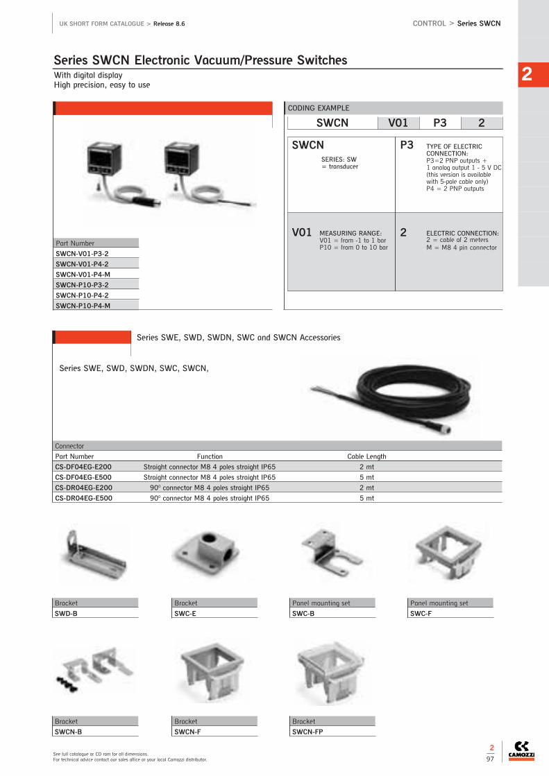
2
See full catalogue or CD rom for all dimensions.For technical advice contact our sales office or your local Camozzi distributor.
UK SHORT FORM CATALOGUE > Release 8.6
2
97
Series SWE, SWD, SWDN, SWC and SWCN Accessories
Connector
Part Number Function Cable Length
CS-DF04EG-E200 Straight connector M8 4 poles straight IP65 2 mt
CS-DF04EG-E500 Straight connector M8 4 poles straight IP65 5 mt
CS-DR04EG-E200 90O connector M8 4 poles straight IP65 2 mt
CS-DR04EG-E500 90O connector M8 4 poles straight IP65 5 mt
CONTROL > Series SWCN
With digital displayHigh precision, easy to use
Series SWE, SWD, SWDN, SWC, SWCN,
Series SWCN Electronic Vacuum/Pressure Switches
Part Number
SWCN-V01-P3-2
SWCN-V01-P4-2
SWCN-V01-P4-M
SWCN-P10-P3-2
SWCN-P10-P4-2
SWCN-P10-P4-M
CODING EXAMPLE
SWCN V01 P3 2
P3
2
SWCN
V01
TYPE OF ELECTRIC CONNECTION:P3=2 PNP outputs + 1 analog output 1 - 5 V DC(this version is available with 5-pole cable only)P4 = 2 PNP outputs
ELECTRIC CONNECTION:2 = cable of 2 metersM = M8 4 pin connector
SERIES: SW = transducer
MEASURING RANGE:V01 = from -1 to 1 bar P10 = from 0 to 10 bar
Panel mounting set
SWC-B
Bracket
SWC-E
Bracket
SWD-B
Panel mounting set
SWC-F
Bracket
SWCN-FP
Bracket
SWCN-F
Bracket
SWCN-B

CONTROL
2
The company reserves the right to vary models and dimensions without notice.Products designed for industrial applications. General terms and conditions for sale are available on www.camozzi.co.uk
UK SHORT FORM CATALOGUE > Release 8.6
Connections: M5, 1/8, 1/4, 3/8, 1/2, 3/4, 1
Series 2901, 2903, 2921, 2931, 2938, 2939, SP, RSW Silencers
CONTROL > Series 2901, 2903, 2921, 2931, 2938, 2939, SP, RSW
Part Number Flow Rate Noise
Nl/min db (A)
2921 1/8 1550 78
2921 1/4 2400 79
2921 3/8 4800 84
2921 1/2 6800 84
2921 3/4 12700 78
2921 1 >15000 80
Part Number Flow Rate Noise
Nl/min db (A)
2903 1/8 700 74
Part Number Flow Rate Noise
Nl/min db (A)
2901 1/8 700 75
2901 1/4 - 17 1000 78
2901 1/4 - 22 1600 92
2901 3/8 1500 76
2901 1/2 3400 86
2901 3/4 4100 87
2901 1 7600 88
Part Number Flow Rate Noise
Nl/min db (A)
2939 4 335 80
2939 6 632 79
2939 8 1229 89
2939 10 2650 87
Part Number Flow Rate Noise
Nl/min db (A)
2938M5 546 67
2938 1/8 1441 65
2938 1/4 2752 79
2938 3/8 4735 73
2938 1/2 8534 86
Part Number Flow Rate Noise
Nl/min db (A)
2931M5 450 69
2931M7 1130 76
2931 1/8 1819 83
2931 1/4 2675 85
2931 3/8 4863 83
2931 1/2 7085 84
2931 3/4 12733 78
2931 1 >15000 82
Part
Number
SCO 604-1/8+2905 1/8
SCO 606-1/4+2905 1/4
Part
Number
SP 1/8
SP 1/4
SP 3/8
SP 1/2
2
98
Part Number Flow Rate
Nl/min
RSW 1/8 410
RSW 1/4 650
RSW 1/2 1590
SIL1 SIL1 SIL1
SIL1
SIL1
SIL1 SIL1
RSW1 RSW1

2
See full catalogue or CD rom for all dimensions.For technical advice contact our sales office or your local Camozzi distributor.
UK SHORT FORM CATALOGUE > Release 8.6
2
99
Series ER100 Digital Electro-Pneumatic Regulators Connections: 1/4
ER104-50APER104-50SP
ER104-52APER104-52SP
ER104-5PSPER104-90AP
ER104-90SPER104-92AP
ER104-92SPER104-9PSP
MODELS
Accessories
Bracket Floor installation type
Bracket Wall installation type
CODING EXAMPLE
SERIES: ER
ER 1 04 - 5 0 AN
ER
1
04
5
0
AN
CONNECTIONS:04 = 1/4
INPUT:0 = 0 - 10 V DC1 = 0 - 5 V DC2 = 4 - 20 mAP = Parallel 10 bit
SIZE:1 = size 1
WORKING PRESSURE:5 = 0 - 5 bar9 = 0.5 - 9 bar
OUTPUT:AN = 1 - 5 V analog, error (NPN)AP = 1 - 5 V analog, error (PNP)SN = switch (NPN), error (NPN) SP = switch (PNP), error (PNP)
Part Number
ER1-B1
Part Number
ER1-B2
Please contact the Camozzi sales office for full technical information
CONTROL > Series ER100

CONTROL
2
The company reserves the right to vary models and dimensions without notice.Products designed for industrial applications. General terms and conditions for sale are available on www.camozzi.co.uk
UK SHORT FORM CATALOGUE > Release 8.6
2
100
Ports 1/4 and 3/8
Series ER200 Digital Electro-Pneumatic Regulators
ER238-50APER238-50SP
ER238-52APER238-52SP
ER238-5PSPER238-90AP
ER238-90SPER238-92AP
ER238-92SPER238-9PSP
MODELS
Accessories
Bracket Floor installation type mounting
Cable and connector for regulatorwith analog Input
Bracket Wall installation type mounting
Cable and connector for regulatorwith parallel Input
CODING EXAMPLE
SERIES: ER
ER 2 04 - 5 0 AN
ER
2
04
5
0
AN
CONNECTIONS:04 = 1/438 = 3/8
INPUT:0 = 0 - 10 V DC1 = 0 - 5 V DC2 = 4 - 20 mAP = Parallel 10 bit
SIZE:2 = size 2
WORKING PRESSURE:5 = 0 - 5 bar9 = 0.5 - 9 bar
OUTPUT:AN = 1 - 5 V analog, error (NPN)AP = 1 - 5 V analog, error (PNP)SN = switch (NPN), error (NPN) SP = switch (PNP), error (PNP)
Part Number
ER2-B1
Part Number
ER2-B2
Part Number
G8X1-1
G8X1-3
Part Number
G8X2-1
G8X2-3
Please contact the Camozzi sales office for full technical information
CONTROL > Series ER200

2
See full catalogue or CD rom for all dimensions.For technical advice contact our sales office or your local Camozzi distributor.
UK SHORT FORM CATALOGUE > Release 8.6
2
101
L R W A 2 - 3 4 - 1 - A - 00
L
R
W
A
2
3
4
1
A
00
MODEL:0 = cartridge with fixation slot (LRWA only)2 = compact DIN-RAIL4 = with sub-base (LRWA only)
INPUT SIGNAL:1 = +/- 10 V2 = 0-10 V3 = 0-20 MA4 = +/- 5 V (LRWA only)4 = 4-20mA (LRWD2 only)
VERSION:W = flow control
FUNCTION:3 = 3 way
FEEDBACK SIGNAL:A = internal encoder
Series LR Servo Valves
CODING EXAMPLE
Flow control
LRWA03/3 way servo valves
Pressure control
LRPA43/3 way servo valves
Positioning control of pneumatic cylinders
LRXA43/3 way servo valves
Digital proportional servo valve
LRWD23/3 way directly operated servo valves
Flow control
LRWA43/3 way servo valves
Flow control
LRWA23/3 way directly operated servo valves
Accessories
Fitting block
LRA0C-3
Connector
CS-PM07CB
Connector
CS-PM04CB
Connector
CS-PF07CB
Cables
CS-LF05HB-D200/D500
CS-LR05HB-D200/D500
SERIES: L = Proportional servo valves
TECHNOLOGY:R = rotating spool
DIAMETER:4 = 4mm6 = 6mm
CABLE:00 = no cable (LRWA2, LRWA4
and LRWD2)05 = 0.5m (LRWA0 only)10 = 1m (LRWA0 only)20 = 2m (LRWA0 only)
ELECTRONICS:A = analogueD = digital (LRWD2 only)
CONTROL > Series LR
New

CONTROL
2
The company reserves the right to vary models and dimensions without notice.Products designed for industrial applications. General terms and conditions for sale are available on www.camozzi.co.uk
UK SHORT FORM CATALOGUE > Release 8.6
2
102
Series K8P Electronic Proportional Micro Regulator
CONTROL > Series K8P
Proportional regulator for pressure control
Series K8P electronic proportional micro regulators have evolved from our Series K8 mini-solenoid valves. Series K8P regulators guarantee excellent pressure regulation, fast responsetimes, self regulation and low energy consumption. Series K8P is a highperformance proportional pressure regulator which is suitable for use in allapplications where high precision, quick response times and low consumption arerequired. The K8P regulator adjusts the outlet pressure through the operation of two K8 monostable valves according to the inlet signal (from 0 to 10 V DC) and to the retroactivity of the internal pressure sensor. A self-adjusting function has been integrated into the regulator control algorithm to guarantee the highest levels of performance apart from the volume connected.
MALE CONNECTOR M8 4 POLESPin 1: +24 V DC (Power supply)Pin 2: Command analogical signal 0-10 V DC
or 4-20 mAPin 3: 0 V (Ground) common also for the
command signalPin 4: Output analogical signal (according to the
regulated pressure)
5 red LED6 green LED
Technical DataMediaInert gasMax Inlet Pressure11 bar (0.5 - 10 bar)4 bar (0.15 - 3 bar)Analogical Input0-10 V DC 4-20mA Ripple ≤ 0.2%Analogical Output0.5-9.5V (feedback)Maximum FlowInlet P 10 bar - regulated P6 bar 12 l/minInlet P 4 bar - regulated P3 bar 6 l/minOperating PressureSee technical data page 2/9
Supply/Use24 V- ~1WFunction3/2 NCLinearity≤ ± 1% FSHysteresis± 0.5% FSRepeatability± 0.5% FSMinimal Set Point Change 50mV => 50 mB (10 bar) - 100mV => 30 mB (3bar)Electrical Connection M8 4 Pin (male)
Part Number
K8P-0-D5*2-0
K8P-0-E5*2-0
K8P-L-E5*2-0
K8P-L-D5*2-0
K8P-S-D5*2-0
K8P-S-E5*2-0
K8P-T-D5*2-0
K8P-T-E5*2-0
Series K8P Electronic Proportional Micro Regulator - Dimensions
Note to the table*according to the type ofcommand desired, insert:2 (0-10 V DC) or 3 (4-20mA)
New

2
See full catalogue or CD rom for all dimensions.For technical advice contact our sales office or your local Camozzi distributor.
UK SHORT FORM CATALOGUE > Release 8.6 CONTROL > Series K8P
CODING EXAMPLE
K8P - 0 - D 5 2 2 - 0
K8P0
D
5
2
2
0
SERIES: K8P
VALVE FUNCTIONS5 = 2-way NC
BODY DESIGN:0 = Stand aloneS = Standard Sub-baseL = Light Sub-baseT = Light Sub-base for the pressure remote reading
OUTPUT SIGNAL:2 = 0-10 V
Standard Sub-base
Note: the use of a silencer on the exhaust isrecommended* *Mod. 2939 4
Light Sub-base
Note: the use of a silencer on the exhaust isrecommended* * Mod. 2931 M5
Mod. 2938 M5Mod. 2901 M5
Light Sub-base for the pressure remote reading
Note: the use of a silencer on the exhaust isrecommended* * Mod. 2931 M5
Mod. 2938 M5 Mod. 2901 M5
In the version Light sub-base for the pressureremote reading it is also possible to use thefixing bracket B2-E531
Sub-bases
WORKING PRESSURE:D = 0 -10 barE = 0 - 3 bar
COMMAND:2 = 0-10 V DC3 = 4-20 mA
APPLICATIONSThe K8P proportional regulator can be used as a pilot valve to control theopening of high flow valves or to check the high flow pressure regulatorsproportionally (version with sub-base for the pressure remote reading). Itenables proportional control of power in lifting systems and can be used withinert gas to maintain a constant pressure in pneumatic cylinders orexpansion valve chambers. It has also been designed to maintain a constantpressure during the pulling power applied to the wires in winding machines, tomodulate pressure during the smoothing process in woodworking machines orto adjust the opening of diaphragm valves.
CABLE LENGTH:0 = without cable2F = straight cable, 2 m2R = right angle cable (90°), 2 m5F = straight cable, 5 m5R = right angle cable (90°), 5 m
Part Number
K8P-AS
Part Number
K8P-AL
Part Number
K8P-AT
Part Number
PCF-K8P
Part Number
K8P-B1Part Number Type of Connector Cable Length (m)
CS-DF04EG-E200 straight 2
CS-DF04EG-E500 straight 5
CS-DR04EG-E200 right angle (90°) 2
CS-DR04EG-E500 right angle (90°) 5
Mounting Bracket for DIN rail(7.5mm x 35mm - width 1)
Supplied with:1x plate1x screw M4x6 UNI 5931Note: this accessory cannot be usedwith the light sub-base version.
Circular M8 4-pole connectors, FemaleWith PU sheathing, non shieldedcable.Protection class: IP65
Bracket for Horizontal MountingSupplied with:1x mounting bracket2x screws M3x8 UNI 5931
Series K8P Accessories
2
103
New

Part Number Connection 1 Connection 2 Function Orifice Ø (mm) Kv (l/min) Pressure Max (bar)
AP-6210-DR2-GP* M5 M5 2/2 N.C. 0.8 0.4 10
AP-6210-FR2-GP* M5 M5 2/2 N.C. 1 0.5 8
AP-6210-HR2-GP* M5 M5 2/2 N.C. 1.2 0.65 6
AP-6210-LR2-GP* M5 M5 2/2 N.C. 1.6 1.2 4
CONTROL
2
The company reserves the right to vary models and dimensions without notice.Products designed for industrial applications. General terms and conditions for sale are available on www.camozzi.co.uk
UK SHORT FORM CATALOGUE > Release 8.6
2
104
Series AP Directly Operated Proportional Valves 2/2-way proportional valves, NCSize 16 - 22 mm
Series AP directly operated 2/2-way proportional solenoid valves, NC, with nominal diameters range from 0.8 to 2.4mm, can be used where an open loop flow control is required, with gas mixtures, to control free flows or blows, or emptying chambers using vacuum.The proportional valves Series AP have been manufactured to optimise andreduce friction and stick-slip effects.The output flow is proportional to the control signal.As they can work also in vacuum, a minimum working pressure is not required.
CONTROL > Series AP
Technical DataType of ConstructionProportional directly operated Mediainert gasOperating PressureSee technical data page 2/9KvSee technical data page 2/9Operating Temperature0oC to +60oC MaterialsBody: Brass / PVDF (for size 16mm only)Seals: NBRConnectionsM5 - 1/8Hysteresis16mm size <7% 22mm size <5%Repeatibility16mm size <5% 22mm size <3%Special RequestsFor assistance, contact our technicaloffice or your local Camozzidistributor.
Series AP Proportional Valves - Size 16mm
For connectors see page 2/48 - 2/51
16mm 22mm 16mm PVDF
Pressure Part Number Connection 1 Connection 2 Function Orifice Ø (mm) Kv (l/min) Pressure Max (bar)
AP-7211-FR2-U7* 1/8 1/8 2/2 N.C. 1 0.5 10
AP-7211-HR2-U7* 1/8 1/8 2/2 N.C. 1.2 0.65 8
AP-7211-LR2-U7* 1/8 1/8 2/2 N.C. 1.6 1.0 6
AP-7211-NR2-U7* 1/8 1/8 2/2 N.C. 2 1.6 5
AP-7211-QR2-U7* 1/8 1/8 2/2 N.C. 2.4 2.0 4
Series AP Proportional Valves - Size 22mm
Part Number Connection 1 Connection 2 Function Orifice Ø (mm) Kv (l/min) Pressure Max (bar)
AP-621L-DR3-GP* Ø6** Ø6** 2/2 N.C. 0.8 0.4 10
AP-621L-FR3-GP* Ø6** Ø6** 2/2 N.C. 1 0.5 8
AP-621L-HR3-GP* Ø6** Ø6** 2/2 N.C. 1.2 0.65 6
AP-621L-LR3-GP* Ø6** Ø6** 2/2 N.C. 1.6 1.2 4
Series AP Proportional Valves - Size 16mm - body in PVDF
New

2
See full catalogue or CD rom for all dimensions.For technical advice contact our sales office or your local Camozzi distributor.
UK SHORT FORM CATALOGUE > Release 8.6 CONTROL > Series AP
2
105
Proportional valves Series AP
Size 16 mm Size 22 mm Size 16 mm PVDF
CODING EXAMPLE
AP - 7 2 1 1 - L R 2 - G 7 11
AP7
2
1
1
L
R
2
G
7
11
SERIES: AP
VALVE FUNCTIONS1 = NC
BODY:6 = Size 16 mm7 = Size 22 mm
SEALS MATERIAL:R = NBR
NUMBER OF WAYS2 = 2-way
BODY MATERIAL:2 = brass3 = technopolymer (for size 16mm only)
CONNECTIONS:0 = M5 (for size 16mm only)1 = 1/8 (for size 22mm only)L = bar fittings (technopolymer body only
NOMINAL DIAMETER:D = ø 0.8 mm (for size 16mm only)F = ø 1mmH = ø 1.2mmL = ø 1.6mmN = ø 2mm (for size 22mm only)Q = ø 2.4mm (for size 22mm only)
ENCAPSULATING MATERIALG = PA (for size 16mm only)U = PET (for size 22mm only)
SOLENOID DIMENSIONSP = 16x26 DIN EN 175301-803-C (for size 16mm only)7 = 22x22 DIN 43650 B (for size 22mm only)
SOLENOID VOLTAGEH = 12 V DC 3 W (for size 16mm only)7 = 24 V DC 3 W (for size 16mm only)11 = 24 V DC 6.5 W (for size 22mm only)12 = 12 V DC 6.5 W (for size 22mm only)
Series AP Directly Operated Proportional Valves
New

CONTROL
2
The company reserves the right to vary models and dimensions without notice.Products designed for industrial applications. General terms and conditions for sale are available on www.camozzi.co.uk
UK SHORT FORM CATALOGUE > Release 8.6
2
106
G1/2Modular - Available with built-in pressure gauges or ports for gauges
Series MX-PRO Electronic Proportional Regulator
Technical DataType of ConstructionModular, compact, diaphragm type
MediaFiltered air, class 5.4.4 according toISO 8573-1, inert gas
Flow RateSee full catalogue
Working TemperatureFrom 0oC to +50oC
Inlet Pressure0 - 11 bar (10 bar)0 - 4 bar (3 bar)
Outlet Pressure0.5 - 10 bar0.15 - 3 bar
Overpressure exhaustWith relieving (standard)Without relieving
Analogical input0-10 V DC Ripple ≤0.2%4 - 20mA
Analogical output0.5 - 9.5 V DC (feedback)
Supply / Comsumption19-28 V DC - ~1 W
Protection ClassIP51 with connectorElectrical ConnectionM8 4 Pin (male)MaterialsBody: AluminiumCovering: PolyacetalValve Holder Plug: PolyacetalUpper Base: AluminiumLower Spring: Zinc-Plated SteelDiaphragm: NBRSeals: NBRSpecial RequestsFor assistance, contact our technicaloffice or your local Camozzidistributor.
CODING EXAMPLE
MX 2 - 1/2 - R CV 2 0 4 - LH
MX
2
1/2
SERIES: MX
SIZE:2 = G1/2
CONNECTIONS:1/2= G1/2
TYPE OF REGULATOR:R = Pressure regulatorM = Manifold pressure
regulator (G1/2 only)
OPERATING PRESSURE (1 bar = 14.5psi):1 = 0.15 - 3 bar2 = 0.5 - 10 bar (standard)
COMMAND:CV = electrical command
0-10 V DCCA = electrical command
4-20 mA
R
CV
2
0
4
LH
DESIGN TYPE:0 = relieving (standard)1 = without relieving
PRESSURE GAUGE:0 = without pressure gauge (with
threaded connection for gauges)2 = with built-in pressure gauge 0-6
and working pressure 0.15 - 3 bar4 = with built-in pressure gauge 0-12
and working pressure 0.5 - 10 bar(standard)
FLOW DIRECTION:= from left to right (standard)
LH = from right to left
Part Number
MX2-1/2-RCV204
MX2-1/2-MCV204
New
CONTROL > Series MX-PRO

3 > Treatment
TREATM
ENT
3 3 / 14 Series MCFilters
3 / 14 Series MCCoalescing Filters
3 / 15 Series MCPressure Regulators
3 / 15 Series MCLubricators
3 / 16 Series MCFilter-Regulators
3 / 16 Series MCLockable isolation 3/2-Way Valves
3 / 17 Series MC 3/2 Valve Pneumatically orElectropneumatically Operated
3 / 17 Series MCSoft Start Valves
3 / 17 Series MCTake-off Blocks
3 / 18 Series MC Assembled FRL
3 / 22 Series MC Assembly Manifold Regulators
Modular FRL Units - 3/8, 1/2, 3/4 and 1
3 / 2 Series MXFilters
3 / 2 Series MX Activated Carbon Filters
3 / 3 Series MXCoalescing Filters
3 / 4 Series MXPressure Regulators
3 / 5 Series MXLubricators
3 / 6 Series MXFilter-Regulators
3 / 8 Series MXLockable Isolation3/2-Way Valves
3 / 8 Series MXSoft Start Valves
3 / 9 Series MXTake-off Blocks
3 / 9 Series MXAssembled FRL
Modular FRL Units - 1/4

3FRL Units - 1/8 and 1/4
3 / 25 Series NFilters and Coalescing Filters
3 / 26 Series NPressure Regulators
3 / 26 Series NLubricators
3 / 27 Series N Filter/Regulators
Pressure Regulators
3 / 23 Series CLR Micro Pressure Regulators
3 / 24 Series MPressure Micro Regulator
3 / 24 Series TPressure Micro Regulators
3 / 27 Pressure Gauges
3 / 28 Series MX, MC, M, N, and T Accessories for Air Treatment
3 / 30 Series MX, MC and NFunctioning Condensate Drains
Pressure Gauges and Accessories for Air Treatment

TREATM
ENT
3
The company reserves the right to vary models and dimensions without notice.Products designed for industrial applications. General terms and conditions for sale are available on www.camozzi.co.uk
TREATMENT > Series MX UK SHORT FORM CATALOGUE > RELEASE 8.6
3
2
Connections: MX2=3/8, 1/2, 3/4 MX3=3/4, 1ModularBowl with technopolymer cover and bayonet-type mounting
Series MX Filters
CODING EXAMPLE
MX 2 - 3/8 - F 0 0
MX
2
3/8
F
0
0
SERIES: MX
SIZE:2 = 3/8 - 1/2 - 3/43 = 3/4 - 1
CONNECTIONS:3/8, 1/2, 3/4, 1
F = filter
FILTERING ELEMENT:0 = 25µm (standard)1 = 5µm
DRAINING OF CONDENSATE:0= semi-automatic manual drain
(standard)3 = automatic drain5 = depressuring drain, protected8= no drain with connection 1/8see page 3/30
Connections: MX2=3/8, 1/2, 3/4 MX3=3/4, 1ModularBowl with technopolymer cover and bayonet-type mounting
Series MX Activated Carbon Filters
CODING EXAMPLE
MX 2 - 3/8 - FCA
MX
2
3/8
FCA
SERIES: MX
SIZE:2 = 3/8 - 1/2 - 3/43 = 3/4 - 1
CONNECTIONS:3/8, 1/2, 3/4, 1
Activated carbon filter
MX2 MX3
MX2 MX3
25 micron 3/8 1/2 3/4 3/4 1
Semi Auto Drain MX2-3/8-F00 MX2-1/2-F00 MX2-3/4-F00 MX3-3/4-F00 MX3-1-F00Automatic Drain MX2-3/8-F03 MX2-1/2-F03 MX2-3/4-F03 MX3-3/4-F03 MX3-1-F03Depressurisation Drain Protected MX2-3/8-F05 MX2-1/2-F05 MX2-3/4-F05 MX3-3/4-F05 MX3-1-F05Connection 1/8 MX2-3/8-F08 MX2-1/2-F08 MX2-3/4-F08 MX3-3/4-F08 MX3-1-F08
5 micron 3/8 1/2 3/4 3/4 1
Semi Auto Drain MX2-3/8-F10 MX2-1/2-F10 MX2-3/4-F10 MX3-3/4-F10 MX3-1-F10Automatic Drain MX2-3/8-F13 MX2-1/2-F13 MX2-3/4-F13 MX3-3/4-F13 MX3-1-F13Depressurisation Drain Protected MX2-3/8-F15 MX2-1/2-F15 MX2-3/4-F15 MX3-3/4-F15 MX3-1-F15Connection 1/8 MX2-3/8-F18 MX2-1/2-F18 MX2-3/4-F18 MX3-3/4-F18 MX3-1-F18
MX2 MX3Activated Carbon Filters 3/8 1/2 3/4 3/4 1
MX2-3/8-FCA MX2-1/2-FCA MX2-3/4-FCA MX3-3/4-FCA MX3-1-FCA
FT01
FT02
FT03
FC01

3
See full catalogue or CD rom for all dimensions.For technical advice contact our sales office or your local Camozzi distributor.
TREATMENT > Series MXUK SHORT FORM CATALOGUE > RELEASE 8.6
3
3
Connections: MX2=3/8, 1/2, 3/4 MX3=3/4, 1ModularBowl with technopolymer cover and bayonet-type mounting
Series MX Coalescing Filters
CODING EXAMPLE
MX 2 - 3/8 - FC 0 0
MX
2
3/8
SERIES: MX
SIZE:2 = 3/8 - 1/2 - 3/43 = 3/4 - 1
CONNECTIONS:3/8, 1/2, 3/4, 1
FC = coalesing filter
FILTERING ELEMENT:0 = 0.01µm (standard)1 = 1µm
DRAINING OF CONDENSATE:0= semi-automatic manual drain
(standard)3 = automatic drain5 = depressuring drain, protected8= no drain with connection 1/8 see page 3/30
FC
0
0
MX2 MX3
MX2 MX3
0.01 micron 3/8 1/2 3/4 3/4 1
Semi Auto Drain MX2-3/8-FC00 MX2-1/2-FC00 MX2-3/4-FC00 MX3-3/4-FC00 MX3-1-FC00Automatic Drain MX2-3/8-FC03 MX2-1/2-FC03 MX2-3/4-FC03 MX3-3/4-FC03 MX3-1-FC03Depressurisation Drain Protected MX2-3/8-FC05 MX2-1/2-FC05 MX2-3/4-FC05 MX3-3/4-FC05 MX3-1-FC05Connection 1/8 MX2-3/8-FC08 MX2-1/2-FC08 MX2-3/4-FC08 MX3-3/4-FC08 MX3-1-FC08
1 micron 3/8 1/2 3/4 3/4 1
Semi Auto Drain MX2-3/8-FC10 MX2-1/2-FC10 MX2-3/4-FC10 MX3-3/4-FC10 MX3-1-FC10Automatic Drain MX2-3/8-FC13 MX2-1/2-FC13 MX2-3/4-FC13 MX3-3/4-FC13 MX3-1-FC13Depressurisation Drain Protected MX2-3/8-FC15 MX2-1/2-FC15 MX2-3/4-FC15 MX3-3/4-FC15 MX3-1-FC15Connection 1/8 MX2-3/8-FC18 MX2-1/2-FC18 MX2-3/4-FC18 MX3-3/4-FC18 MX3-1-FC18
FA01
FA02
FA03
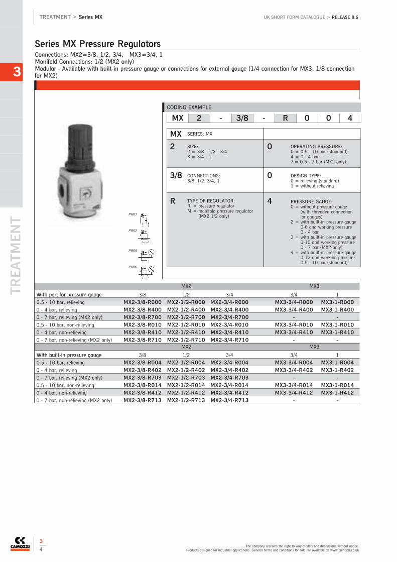
TREATM
ENT
3
The company reserves the right to vary models and dimensions without notice.Products designed for industrial applications. General terms and conditions for sale are available on www.camozzi.co.uk
TREATMENT > Series MX UK SHORT FORM CATALOGUE > RELEASE 8.6
3
4
Connections: MX2=3/8, 1/2, 3/4, MX3=3/4, 1Manifold Connections: 1/2 (MX2 only)Modular - Available with built-in pressure gauge or connections for external gauge (1/4 connection for MX3, 1/8 connectionfor MX2)
Series MX Pressure Regulators
CODING EXAMPLE
MX 2 - 3/8 - R 0 0 4
MX
2
3/8
R
0
0
4
SERIES: MX
SIZE:2 = 3/8 - 1/2 - 3/43 = 3/4 - 1
CONNECTIONS:3/8, 1/2, 3/4, 1
TYPE OF REGULATOR:R = pressure regulatorM = manifold pressure regulator
(MX2 1/2 only)
OPERATING PRESSURE:0 = 0.5 - 10 bar (standard)4 = 0 - 4 bar7 = 0.5 - 7 bar (MX2 only)
DESIGN TYPE:0 = relieving (standard)1 = without relieving
PRESSURE GAUGE:0 = without pressure gauge
(with threaded connectionfor gauges)
2 = with built-in pressure gauge0-6 and working pressure 0 - 4 bar
3 = with built-in pressure gauge0-10 and working pressure0 - 7 bar (MX2 only)
4 = with built-in pressure gauge0-12 and working pressure0.5 - 10 bar (standard)
MX2 MX3
MX2 MX3
With port for pressure gauge 3/8 1/2 3/4 3/4 1
0.5 - 10 bar, relieving MX2-3/8-R000 MX2-1/2-R000 MX2-3/4-R000 MX3-3/4-R000 MX3-1-R0000 - 4 bar, relieving MX2-3/8-R400 MX2-1/2-R400 MX2-3/4-R400 MX3-3/4-R400 MX3-1-R4000 - 7 bar, relieving (MX2 only) MX2-3/8-R700 MX2-1/2-R700 MX2-3/4-R700 - -0.5 - 10 bar, non-relieving MX2-3/8-R010 MX2-1/2-R010 MX2-3/4-R010 MX3-3/4-R010 MX3-1-R0100 - 4 bar, non-relieving MX2-3/8-R410 MX2-1/2-R410 MX2-3/4-R410 MX3-3/4-R410 MX3-1-R4100 - 7 bar, non-relieving (MX2 only) MX2-3/8-R710 MX2-1/2-R710 MX2-3/4-R710 - -
With built-in pressure gauge 3/8 1/2 3/4 3/4 1
0.5 - 10 bar, relieving MX2-3/8-R004 MX2-1/2-R004 MX2-3/4-R004 MX3-3/4-R004 MX3-1-R0040 - 4 bar, relieving MX2-3/8-R402 MX2-1/2-R402 MX2-3/4-R402 MX3-3/4-R402 MX3-1-R4020 - 7 bar, relieving (MX2 only) MX2-3/8-R703 MX2-1/2-R703 MX2-3/4-R703 - -0.5 - 10 bar, non-relieving MX2-3/8-R014 MX2-1/2-R014 MX2-3/4-R014 MX3-3/4-R014 MX3-1-R0140 - 4 bar, non-relieving MX2-3/8-R412 MX2-1/2-R412 MX2-3/4-R412 MX3-3/4-R412 MX3-1-R4120 - 7 bar, non-relieving (MX2 only) MX2-3/8-R713 MX2-1/2-R713 MX2-3/4-R713 - -
PR01
PR02
PR05
PR06

3
See full catalogue or CD rom for all dimensions.For technical advice contact our sales office or your local Camozzi distributor.
TREATMENT > Series MXUK SHORT FORM CATALOGUE > RELEASE 8.6
3
5
MX2 MX3
MX2 MX3
With port for pressure gauge 3/8 1/2 3/4 3/4 1
0.5 - 10 bar, relieving - MX2-1/2-M000 - - -0 - 4 bar, relieving - MX2-1/2-M400 - - -0 - 7 bar, relieving - MX2-1/2-M700 - - -0.5 - 10 bar, non-relieving - MX2-1/2-M010 - - -0 - 4 bar, non-relieving - MX2-1/2-M410 - - -0 - 7 bar, non-relieving - MX2-1/2-M710 - - -
With built-in pressure gauge 3/8 1/2 3/4 3/4 1
0.5 - 10 bar, relieving - MX2-1/2-M004 - - -0 - 4 bar, relieving - MX2-1/2-M402 - - -0 - 7 bar, relieving - MX2-1/2-M703 - - -0.5 - 10 bar, non-relieving - MX2-1/2-M014 - - -0 - 4 bar, non-relieving - MX2-1/2-M412 - - -0 - 7 bar, non-relieving - MX2-1/2-M713 - - -
Connections: MX2=3/8, 1/2, 3/4 MX3=3/4, 1ModularBowl with technopolymer cover and bayonet-type mounting
Series MX Lubricators
CODING EXAMPLE
MX 2 - 3/8 - L 00
MX
2
3/8
L
00
SERIES: MX
SIZE:2 = 3/8 - 1/2 - 3/43 = 3/4 - 1
CONNECTIONS:3/8, 1/2, 3/4, 1
L = lubricator
DESIGN TYPE:00 = atomized oil
MX2 MX3Connection 3/8 1/2 3/4 3/4 1
Part Number MX2-3/8-L00 MX2-1/2-L00 MX2-3/4-L00 MX3-3/4-L00 MX3-1-L00
LU0
Series MX Manifold Pressure Regulators
FR19

TREATM
ENT
3
The company reserves the right to vary models and dimensions without notice.Products designed for industrial applications. General terms and conditions for sale are available on www.camozzi.co.uk
TREATMENT > Series MX UK SHORT FORM CATALOGUE > RELEASE 8.6
3
6
CODING EXAMPLE
MX 2 - 3/8 - FR 0 0 0 4
MX
2
3/8
FR
0
0
0
4
SERIES: MX
SIZE:2 = 3/8 - 1/2 - 3/43 = 3/4 - 1
CONNECTIONS:3/8, 1/2, 3/4, 1
FR= filter regulator
DRAINING OF CONDENSATE:0= semi-automatic manual drain
(standard)3 = automatic drain5 = depressuring drain, protected8= no drain with connection 1/8
FILTERING ELEMENT WITH DESIGN TYPE:0 = 25µm with relieving (standard)1 = 5µm with relieving2 = 25µm without relieving3 = 5µm without relieving
OPERATING PRESSURE:0 = 0.5 - 10 bar (standard)4 = 0 - 4 bar7 = 0.5 - 7 bar (MX2 only)
Connections: MX2=3/8, 1/2, 3/4 MX3=3/4, 1ModularBowl with technopolymer cover and bayonet-type mounting
Series MX Filter/Regulator
MX2Pressure Regulators - With port for pressure gauge
Semi Auto Drain - Self Relieving 3/8 1/2 3/4 3/4 1
25 Micron 0.5 - 10 bar MX2-3/8-FR0000 MX2-1/2-FR0000 MX2-3/4-FR0000 MX3-3/4-FR0000 MX3-1-FR000025 Micron 0 - 4 bar MX2-3/8-FR0040 MX2-1/2-FR0040 MX2-3/4-FR0040 MX3-3/4-FR0040 MX3-1-FR004025 Micron 0 - 7 bar (MX2 only) MX2-3/8-FR0070 MX2-1/2-FR0070 MX2-3/4-FR0070 - -Semi Auto Drain - Non-Relieving 3/8 1/2 3/4 3/4 1
25 Micron 0.5 - 10 bar MX2-3/8-FR2000 MX2-1/2-FR2000 MX2-3/4-FR2000 MX3-3/4-FR2000 MX3-1-FR200025 Micron 0 - 4 bar MX2-3/8-FR2040 MX2-1/2-FR2040 MX2-3/4-FR2040 MX3-3/4-FR2040 MX3-1-FR204025 Micron 0 - 7 bar (MX2 only) MX2-3/8-FR2070 MX2-1/2-FR2070 MX2-3/4-FR2070 - -Automatic Drain - Self Relieving 3/8 1/2 3/4 3/4 1
25 Micron 0.5 - 10 bar MX2-3/8-FR0300 MX2-1/2-FR0300 MX2-3/4-FR0300 MX3-3/4-FR0300 MX3-1-FR030025 Micron 0 - 4 bar MX2-3/8-FR0340 MX2-1/2-FR0340 MX2-3/4-FR0340 MX3-3/4-FR0340 MX3-1-FR034025 Micron 0 - 7 bar (MX2 only) MX2-3/8-FR0370 MX2-1/2-FR0370 MX2-3/4-FR0370 - -Automatic Drain - Non-Relieving 3/8 1/2 3/4 3/4 1
25 Micron 0.5 - 10 bar MX2-3/8-FR2300 MX2-1/2-FR2300 MX2-3/4-FR2300 MX3-3/4-FR2300 MX3-1-FR230025 Micron 0 - 4 bar MX2-3/8-FR2340 MX2-1/2-FR2340 MX2-3/4-FR2340 MX3-3/4-FR2340 MX3-1-FR234025 Micron 0 - 7 bar (MX2 only) MX2-3/8-FR2370 MX2-1/2-FR2370 MX2-3/4-FR2370 - -Depressurisation Drain - Self Relieving 3/8 1/2 3/4 3/4 1
25 Micron 0.5 - 10 bar MX2-3/8-FR0500 MX2-1/2-FR0500 MX2-3/4-FR0500 MX3-3/4-FR0500 MX3-1-FR050025 Micron 0 - 4 bar MX2-3/8-FR0540 MX2-1/2-FR0540 MX2-3/4-FR0540 MX3-3/4-FR0540 MX3-1-FR054025 Micron 0 - 7 bar (MX2 only) MX2-3/8-FR0570 MX2-1/2-FR0570 MX2-3/4-FR0570 - -Depressurisation Drain - Non-Relieving 3/8 1/2 3/4 3/4 1
25 Micron 0.5 - 10 bar MX2-3/8-FR2500 MX2-1/2-FR2500 MX2-3/4-FR2500 MX3-3/4-FR2500 MX3-1-FR250025 Micron 0 - 4 bar MX2-3/8-FR2540 MX2-1/2-FR2540 MX2-3/4-FR2540 MX3-3/4-FR2540 MX3-1-FR254025 Micron 0 - 7 bar (MX2 only) MX2-3/8-FR2570 MX2-1/2-FR2570 MX2-3/4-FR2570 - -Connection 1/8 - Self Relieving 3/8 1/2 3/4 3/4 1
25 Micron 0.5 - 10 bar MX2-3/8-FR0800 MX2-1/2-FR0800 MX2-3/4-FR0800 MX3-3/4-FR0800 MX3-1-FR080025 Micron 0 - 4 bar MX2-3/8-FR0840 MX2-1/2-FR0840 MX2-3/4-FR0840 MX3-3/4-FR0840 MX3-1-FR084025 Micron 0 - 7 bar (MX2 only) MX2-3/8-FR0870 MX2-1/2-FR0870 MX2-3/4-FR0870 - -Connection 1/8 - Non-Relieving 3/8 1/2 3/4 3/4 1
25 Micron 0.5 - 10 bar MX2-3/8-FR2800 MX2-1/2-FR2800 MX2-3/4-FR2800 MX3-3/4-FR2800 MX3-1-FR280025 Micron 0 - 4 bar MX2-3/8-FR2840 MX2-1/2-FR2840 MX2-3/4-FR2840 MX3-3/4-FR2840 MX3-1-FR284025 Micron 0 - 7 bar (MX2 only) MX2-3/8-FR2870 MX2-1/2-FR2870 MX2-3/4-FR2870 - -
PRESSURE GAUGE:0 = without pressure gauge 2 = with built-in pressure gauge 0-6
and working pressure 0-4 bar3 = with built-in pressure gauge 0-10
and working pressure 0-7 bar(MX2 only)
4 = with built-in pressure gauge 0-12and working pressure 0.5 - 10bar (standard)
MX3
FR01
FR02
FR04
FR05
FR10
FR11
FR18
FR03

3
See full catalogue or CD rom for all dimensions.For technical advice contact our sales office or your local Camozzi distributor.
TREATMENT > Series MXUK SHORT FORM CATALOGUE > RELEASE 8.6
3
7
Series MX Filter/Regulator
MX2Pressure Regulators - With built-in pressure gauge
Semi Auto Drain - Self Relieving 3/8 1/2 3/4 3/4 1
25 Micron 0.5 - 10 bar MX2-3/8-FR0004 MX2-1/2-FR0004 MX2-3/4-FR0004 MX3-3/4-FR0004 MX3-1-FR000425 Micron 0 - 4 bar MX2-3/8-FR0042 MX2-1/2-FR0042 MX2-3/4-FR0042 MX3-3/4-FR0042 MX3-1-FR004225 Micron 0 - 7 bar (MX2 only) MX2-3/8-FR0073 MX2-1/2-FR0073 MX2-3/4-FR0073 - -Semi Auto Drain - Non-Relieving 3/8 1/2 3/4 3/4 1
25 Micron 0.5 - 10 bar MX2-3/8-FR2004 MX2-1/2-FR2004 MX2-3/4-FR2004 MX3-3/4-FR2004 MX3-1-FR200425 Micron 0 - 4 bar MX2-3/8-FR2042 MX2-1/2-FR2042 MX2-3/4-FR2042 MX3-3/4-FR2042 MX3-1-FR204225 Micron 0 - 7 bar (MX2 only) MX2-3/8-FR2073 MX2-1/2-FR2073 MX2-3/4-FR2073 - -Automatic Drain - Self Relieving 3/8 1/2 3/4 3/4 1
25 Micron 0.5 - 10 bar MX2-3/8-FR0304 MX2-1/2-FR0304 MX2-3/4-FR0304 MX3-3/4-FR0304 MX3-1-FR030425 Micron 0 - 4 bar MX2-3/8-FR0342 MX2-1/2-FR0342 MX2-3/4-FR0342 MX3-3/4-FR0342 MX3-1-FR034225 Micron 0 - 7 bar (MX2 only) MX2-3/8-FR0373 MX2-1/2-FR0373 MX2-3/4-FR0373 - -Automatic Drain - Non-Relieving 3/8 1/2 3/4 3/4 1
25 Micron 0.5 - 10 bar MX2-3/8-FR2304 MX2-1/2-FR2304 MX2-3/4-FR2304 MX3-3/4-FR2304 MX3-1-FR230425 Micron 0 - 4 bar MX2-3/8-FR2342 MX2-1/2-FR2342 MX2-3/4-FR2342 MX3-3/4-FR2342 MX3-1-FR234225 Micron 0 - 7 bar (MX2 only) MX2-3/8-FR2373 MX2-1/2-FR2373 MX2-3/4-FR2373 - -Depressurisation Drain - Self Relieving 3/8 1/2 3/4 3/4 1
25 Micron 0.5 - 10 bar MX2-3/8-FR0504 MX2-1/2-FR0504 MX2-3/4-FR0504 MX3-3/4-FR0504 MX3-1-FR050425 Micron 0 - 4 bar MX2-3/8-FR0542 MX2-1/2-FR0542 MX2-3/4-FR0542 MX3-3/4-FR0542 MX3-1-FR054225 Micron 0 - 7 bar (MX2 only) MX2-3/8-FR0573 MX2-1/2-FR0573 MX2-3/4-FR0573 - -Depressurisation Drain - Non-Relieving 3/8 1/2 3/4 3/4 1
25 Micron 0.5 - 10 bar MX2-3/8-FR2504 MX2-1/2-FR2504 MX2-3/4-FR2504 MX3-3/4-FR2504 MX3-1-FR250425 Micron 0 - 4 bar MX2-3/8-FR2542 MX2-1/2-FR2542 MX2-3/4-FR2542 MX3-3/4-FR2542 MX3-1-FR254225 Micron 0 - 7 bar (MX2 only) MX2-3/8-FR2573 MX2-1/2-FR2573 MX2-3/4-FR2573 - -Connection 1/8 - Self Relieving 3/8 1/2 3/4 3/4 1
25 Micron 0.5 - 10 bar MX2-3/8-FR0804 MX2-1/2-FR0804 MX2-3/4-FR0804 MX3-3/4-FR0804 MX3-1-FR080425 Micron 0 - 4 bar MX2-3/8-FR0842 MX2-1/2-FR0842 MX2-3/4-FR0842 MX3-3/4-FR0842 MX3-1-FR084225 Micron 0 - 7 bar (MX2 only) MX2-3/8-FR0873 MX2-1/2-FR0873 MX2-3/4-FR0873 - -Connection 1/8 - Non-Relieving 3/8 1/2 3/4 3/4 1
25 Micron 0.5 - 10 bar MX2-3/8-FR2804 MX2-1/2-FR2804 MX2-3/4-FR2804 MX3-3/4-FR2804 MX3-1-FR280425 Micron 0 - 4 bar MX2-3/8-FR2842 MX2-1/2-FR2842 MX2-3/4-FR2842 MX3-3/4-FR2842 MX3-1-FR284225 Micron 0 - 7 bar (MX2 only) MX2-3/8-FR2873 MX2-1/2-FR2873 MX2-3/4-FR2873 - -
MX3
5 Micron also available on request

TREATM
ENT
3
The company reserves the right to vary models and dimensions without notice.Products designed for industrial applications. General terms and conditions for sale are available on www.camozzi.co.uk
TREATMENT > Series MX UK SHORT FORM CATALOGUE > RELEASE 8.6
3
8
Connections: MX2=3/8, 1/2, 3/4 MX3=3/4, 1ModularManual, electro-pneumatic, servo-pilot and pneumatic control
Series MX Lockable Isolation 3/2-Way Valve
CODING EXAMPLE
MX 2 - 3/8 - V 01
MX
2
3/8
V
01
SERIES: MX
SIZE:2 = 3/8 - 1/2 - 3/43 = 3/4 - 1
CONNECTIONS:3/8, 1/2, 3/4, 1
V = 3/2 way valve
DESIGN TYPE:01 = lockable manual control16 = electro-pneumatic control17 = servo-pilot control36 = pneumatic control
MX2 MX33/8 1/2 3/4 3/4 1
Lockable Manual Control MX2-3/8-V01 MX2-1/2-V01 MX2-3/4-V01 MX3-3/4-V01 MX3-1-V01Electro-Pneumatic Control MX2-3/8-V16 MX2-1/2-V16 MX2-3/4-V16 MX3-3/4-V16 MX3-1-V16Servo-Pilot Control MX2-3/8-V17 MX2-1/2-V17 MX2-3/4-V17 MX3-3/4-V17 MX3-1-V17Pneumatic Control MX2-3/8-V36 MX2-1/2-V36 MX2-3/4-V36 MX3-3/4-V36 MX3-1-V36
Connections: MX2=3/8, 1/2, 3/4 MX3=3/4, 1Modular
Series MX Soft Start Valve
CODING EXAMPLE
MX 2 - 3/8 - AV
MX
2
3/8
AV
SERIES: MX
SIZE:2 = 3/8 - 1/2 - 3/43 = 3/4 - 1
CONNECTIONS:3/8, 1/2, 3/4, 1
AV = soft start valve
MX2 MX33/8 1/2 3/4 3/4 1
Soft Start Valve MX2-3/8-AV MX2-1/2-AV MX2-3/4-AV MX3-3/4-AV MX3-1-AV
VN02 EV10
VP01 EV11
AVP1

3
See full catalogue or CD rom for all dimensions.For technical advice contact our sales office or your local Camozzi distributor.
TREATMENT > Series MXUK SHORT FORM CATALOGUE > RELEASE 8.6
3
9
Connections: MX2=1/2 MX3=1
CODING EXAMPLE
MX 2 - 1/2 - B 00
MX
2
1/2
B
00
SERIES: MX
SIZE:2 = 1/23 = 1
= Take-off block
DESIGN TYPE:00 = without no return valve
(standard)01 = with no return valve
MX2 MX3Take-off Blocks - 1/2 - - 1
Without no return valve - MX2-1/2-B00 - - MX3-1-B00With no return valve - MX2-1/2-B01 - - MX3-1-B01
CONNECTIONS:1/2, 1
Series MX Take-off Blocks
Connections MX2=3/8, 1/2, 3/4 MX3=3/4, 1Assembly through rapid clamps
The FRL Series MX can be easily assembled through rapid clamps which allow the connection among single componentscreating an unlimited number of compositions.The FRL groups Series MX are also available in the already mounted version (with a single code).
FRL Series MX Assembled
CODING EXAMPLE
MX 2 - 3/8 - 000014
MX
2
3/8
SERIES: MX
SIZE:2 = 3/8 - 1/2 - 3/43 = 3/4 - 1
CONNECTIONS:3/8 = 3/81/2 = 1/23/4 = 3/41 = 1
GROUP COMPOSITION (WITH BUILT IN PRESSURE GAUGE):000014 = F00 + R004 + L00000015 = FR0004 + L00000016 = V01 + FR0004 + L00000017 = V01 + FR0004000018 = FR0004 + V16 + AV000019 = FR0004 + L00 + V16 + AV000020 = V01 + FR0004 + V16 + AV000021= V01 + FR0004 + L00 + V16 + AV + PRESS. NO000022 = V01 + FR0004 + L00 + V16 + AV + PRESS. NC000023 = V01 + FR0004 + V16 + AV + PRESS. NO000024 = V01 + FR0004 + V16 + AV + PRESS. NCGROUP COMPOSITION (WITH EXTERNAL PRESSURE GAUGE):000025 = F00 + R000 + L00000026 = FR0000 + L00000027 = V01 + FR0000 + L00000028 = V01 + FR0000000029 = FR0000 + V16 + AV000030 = FR0000 + L00 + V16 + AV000031 = V01 + FR0000 + V16 + AV000032 = V01 + FR0000 + L00 + V16 + AV + PRESS. NO000033 = V01 + FR0000 + L00 + V16 + AV + PRESS. NC000034 = V01 + FR0000 + V16 + AV + PRESS. NO000035 = V01 + FR0000 + V16 + AV + PRESS. NC000036 = F13 + FC03
000014
BL01
BL02

TREATM
ENT
3
The company reserves the right to vary models and dimensions without notice.Products designed for industrial applications. General terms and conditions for sale are available on www.camozzi.co.uk
TREATMENT > Series MX UK SHORT FORM CATALOGUE > RELEASE 8.6
3
10
Part Number A B C D F1 F2MX2-3/8-000014 3/8 289 74.5 210 70 104.5 MX2-1/2-000014 1/2 289 74.5 210 70 104.5MX2-3/4-000014 3/4 289 74.5 210 70 104.5MX3-3/4-000014 3/4 345 81 268.5 68 106MX3-1-000014 1 345 81 268.5 68 106
Part Number A B C D F1 F2MX2-3/8-000025 3/8 289 74.5 210 70 104.5 MX2-1/2-000025 1/2 289 74.5 210 70 104.5MX2-3/4-000025 3/4 289 74.5 210 70 104.5MX3-3/4-000025 3/4 345 81 268.5 68 106MX3-1-000025 1 345 81 268.5 68 106
WITH BUILT IN PRESSURE GAUGE WITH EXTERNAL PRESSURE GAUGE
Components:FilterRegulatorLubricatorPressure GaugeBracket
Composition of the assembled group 000014 and 000025
Part Number A B C D F1 F2MX2-1/2-000015 3/8 289 74.5 140 70 104.5 MX2-3/8-000015 1/2 289 74.5 140 70 104.5MX2-3/4-000015 3/4 289 74.5 140 70 104.5MX3-3/4-000015 3/4 345 81 179 68 106MX3-1-000015 1 345 81 179 68 106
Part Number A B C D F1 F2MX2-1/2-000026 3/8 289 74.5 140 70 104.5 MX2-3/8-000026 1/2 289 74.5 140 70 104.5MX2-3/4-000026 3/4 289 74.5 140 70 104.5MX3-3/4-000026 3/4 345 81 179 68 106MX3-1-000026 1 345 81 179 68 106
WITH BUILT IN PRESSURE GAUGE WITH EXTERNAL PRESSURE GAUGE
Components:Filter-regulatorLubricatorPressure GaugeBracket
Composition of the assembled group 000015 and 000026
Part Number A B C D F1 F2MX2-3/8-000016 3/8 289 74.5 210 70 104.5 MX2-1/2-000016 1/2 289 74.5 210 70 104.5MX2-3/4-000016 3/4 289 74.5 210 70 104.5MX3-3/4-000016 3/4 345 81 268.5 68 106MX3-1-000016 1 345 81 268.5 68 106
Part Number A B C D F1 F2MX2-3/8-000027 3/8 289 74.5 210 70 104.5 MX2-1/2-000027 1/2 289 74.5 210 70 104.5MX2-3/4-000027 3/4 289 74.5 210 70 104.5MX3-3/4-000027 3/4 345 81 268.5 68 106MX3-1-000027 1 345 81 268.5 68 106
WITH BUILT IN PRESSURE GAUGE WITH EXTERNAL PRESSURE GAUGE
Composition of the assembled group 000016 and 000027
Components:Lockable isolation 3/2 valveFilter-regulatorLubricatorPressure GaugeBracket

3
See full catalogue or CD rom for all dimensions.For technical advice contact our sales office or your local Camozzi distributor.
TREATMENT > Series MXUK SHORT FORM CATALOGUE > RELEASE 8.6
3
11
Part Number A B C D F1 F2MX2-3/8-000017 3/8 289 74.5 140 70 104.5MX2-1/2-000017 1/2 289 74.5 140 70 104.5MX2-3/4-000017 3/4 289 74.5 140 70 104.5MX3-3/4-000017 3/4 345 81 179 68 106MX3-1-000017 1 345 81 179 68 106
Part Number A B C D F1 F2MX2-3/8-000028 3/8 289 74.5 140 70 104.5MX2-1/2-000028 1/2 289 74.5 140 70 104.5MX2-3/4-000028 3/4 289 74.5 140 70 104.5MX3-3/4-000028 3/4 345 81 179 68 106MX3-1-000028 1 345 81 179 68 106
WITH BUILT IN PRESSURE GAUGE WITH EXTERNAL PRESSURE GAUGE
Components:Lockable isolation 3/2 valveFilter-regulatorPressure GaugeBracket
Composition of the assembled group 000017 and 000028
Part Number A B C D F1 F2MX2-3/8-000018 3/8 289 74.5 210 70 104.5 MX2-1/2-000018 1/2 289 74.5 210 70 104.5MX2-3/4-000018 3/4 289 74.5 210 70 104.5MX3-3/4-000018 3/4 345 81 268.5 68 106MX3-1-000018 1 345 81 268.5 68 106
Part Number A B C D F1 F2MX2-3/8-000029 3/8 289 74.5 210 70 104.5 MX2-1/2-000029 1/2 289 74.5 210 70 104.5MX2-3/4-000029 3/4 289 74.5 210 70 104.5MX3-3/4-000029 3/4 345 81 268.5 68 106MX3-1-000029 1 345 81 268.5 68 106
WITH BUILT IN PRESSURE GAUGE WITH EXTERNAL PRESSURE GAUGE
Components:Filter-regulatorLockable isolation 3/2 valveSoft start valvePressure GaugeBracket
Composition of the assembled group 000018 and 000029
Part Number A B C D F1 F2MX2-3/8-000019 3/8 289 74.5 280 70 104.5MX2-1/2-000019 1/2 289 74.5 280 70 104.5MX2-3/4-000019 3/4 289 74.5 280 70 104.5MX3-3/4-000019 3/4 345 81 358 68 106MX3-1-000019 1 345 81 358 68 106
Part Number A B C D F1 F2MX2-3/8-000030 3/8 289 74.5 280 70 104.5MX2-1/2-000030 1/2 289 74.5 280 70 104.5MX2-3/4-000030 3/4 289 74.5 280 70 104.5MX3-3/4-000030 3/4 345 81 358 68 106MX3-1-000030 1 345 81 358 68 106
WITH BUILT IN PRESSURE GAUGE WITH EXTERNAL PRESSURE GAUGE
Composition of the assembled group 000019 and 000030
Components:Filter-regulatorLubricatorSoft start valvePressure GaugeBracket

TREATM
ENT
3
The company reserves the right to vary models and dimensions without notice.Products designed for industrial applications. General terms and conditions for sale are available on www.camozzi.co.uk
TREATMENT > Series MX UK SHORT FORM CATALOGUE > RELEASE 8.6
3
12
Part Number A B C D F1 F2MX2-3/8-000020 3/8 289 74.5 280 70 104.5MX2-1/2-000020 1/2 289 74.5 280 70 104.5MX2-3/4-000020 3/4 289 74.5 280 70 104.5MX3-3/4-000020 3/4 345 81 358 68 106MX3-1-000020 1 345 81 358 68 106
Part Number A B C D F1 F2MX2-3/8-000031 3/8 289 74.5 280 70 104.5MX2-1/2-000031 1/2 289 74.5 280 70 104.5MX2-3/4-000031 3/4 289 74.5 280 70 104.5MX3-3/4-000031 3/4 345 81 358 68 106MX3-1-000031 1 345 81 358 68 106
WITH BUILT IN PRESSURE GAUGE WITH EXTERNAL PRESSURE GAUGE
Components:Lockable isolation 3/2 valveFilter-regulatorLockable isolation 3/2 valveSoft start valvePressure GaugeBracket
Composition of the assembled group 000020 and 000031
Part Number A B C D F1 F2MX2-3/8-000021 3/8 289 74.5 350 70 104.5MX2-1/2-000021 1/2 289 74.5 350 70 104.5MX2-3/4-000021 3/4 289 74.5 350 70 104.5MX3-3/4-000021 3/4 345 81 447.5 68 106MX3-1-000021 1 345 81 447.5 68 106
Part Number A B C D F1 F2MX2-3/8-000032 3/8 289 74.5 350 70 104.5MX2-1/2-000032 1/2 289 74.5 350 70 104.5MX2-3/4-000032 3/4 289 74.5 350 70 104.5MX3-3/4-000032 3/4 345 81 447.5 68 106MX3-1-000032 1 345 81 447.5 68 106
WITH BUILT IN PRESSURE GAUGE WITH EXTERNAL PRESSURE GAUGE
Components:Lockable isolation 3/2 valveFilter-regulatorLubricatorLockable isolation 3/2 valveSoft start valve + pressure switch (NO)Pressure GaugeBracket
Composition of the assembled group 000021 and 000032
Part Number A B C D F1 F2MX2-3/8-000022 3/8 289 74.5 350 70 104.5MX2-1/2-000022 1/2 289 74.5 350 70 104.5MX2-3/4-000022 3/4 289 74.5 350 70 104.5MX3-3/4-000022 3/4 345 81 447.5 68 106MX3-1-000022 1 345 81 447.5 68 106
Part Number A B C D F1 F2MX2-3/8-000033 3/8 289 74.5 350 70 104.5MX2-1/2-000033 1/2 289 74.5 350 70 104.5MX2-3/4-000033 3/4 289 74.5 350 70 104.5MX3-3/4-000033 3/4 345 81 447.5 68 106MX3-1-000033 1 345 81 447.5 68 106
WITH BUILT IN PRESSURE GAUGE WITH EXTERNAL PRESSURE GAUGE
Composition of the assembled group 000022 and 000033
Components:Lockable isolation 3/2 valveFilter-regulatorLubricatorLockable isolation 3/2 valveSoft start valve + pressure switch (NC)Pressure GaugeBracket

3
See full catalogue or CD rom for all dimensions.For technical advice contact our sales office or your local Camozzi distributor.
TREATMENT > Series MX UK SHORT FORM CATALOGUE > RELEASE 8.6
3
13
Part Number A B C D F1 F2MX2-3/8-000023 3/8 289 74,5 280 70 104,5MX2-1/2-000023 1/2 289 74,5 280 70 104,5MX2-3/4-000023 3/4 289 74,5 280 70 104,5MX3-3/4-000023 3/4 345 81 358 68 106MX3-1-000023 1 345 81 358 68 106
Part Number A B C D F1 F2MX2-3/8-000034 3/8 289 74,5 280 70 104,5MX2-1/2-000034 1/2 289 74,5 280 70 104,5MX2-3/4-000034 3/4 289 74,5 280 70 104,5MX3-3/4-000034 3/4 345 81 358 68 106MX3-1-000034 1 345 81 358 68 106
WITH BUILT IN PRESSURE GAUGE WITH EXTERNAL PRESSURE GAUGE
Components:Lockable isolation 3/2 valveFilter-regulatorLockable isolation 3/2 valveSoft start valve + pressure switch (NO)Pressure GaugeBracket
Composition of the assembled group 000023 and 000034
Part Number A B C D F1 F2MX2-3/8-000024 3/8 289 74.5 280 70 104.5MX2-1/2-000024 1/2 289 74.5 280 70 104.5MX2-3/4-000024 3/4 289 74.5 280 70 104.5MX3-3/4-000024 3/4 345 81 358 68 106MX3-1-000024 1 345 81 358 68 106
Part Number A B C D F1 F2MX2-3/8-000035 3/8 289 74.5 280 70 104.5MX2-1/2-000035 1/2 289 74.5 280 70 104.5MX2-3/4-000035 3/4 289 74.5 280 70 104.5MX3-3/4-000035 3/4 345 81 358 68 106MX3-1-000035 1 345 81 358 68 106
WITH BUILT IN PRESSURE GAUGE WITH EXTERNAL PRESSURE GAUGE
Components:Lockable isolation 3/2 valveFilter-regulatorLockable isolation 3/2 valveSoft start valve + pressure switch (NC)Pressure GaugeBracket
Composition of the assembled group 000024 and 000035
Part Number A B C D F1 F2MX2-3/8-000036 3/8 210 72 140 70 104.5MX2-1/2-000036 1/2 210 72 140 70 104.5MX2-3/4-000036 3/4 210 72 140 70 104.5MX3-3/4-000036 3/4 231 78 179 68 106MX3-1-000036 1 231 78 179 68 106
FILTER SET
Composition of the assembled group 000036
Components:FilterCoalescing filterBracket

Connections: 1/4ModularWith metal bowl and bayonet-type mounting
Series MC Filters
Semi Auto Drain 1/4
25 micron MC104 F005 micron MC104 F10
Coalescing Filter 0.01 Micron 1/4
Semi Auto Drain MC104 FB0Depressurisation Drain MC104 FB4Depressurisation Drain Protected MC104 FB5Connection 1/8 MC104 FB8
Depressurisation Drain 1/4
25 micron MC104 F045 micron MC104 F14
Depressurisation Drain Protected 1/4
25 micron MC104 F055 micron MC104 F15
Connection 1/8 1/4
25 micron MC104 F085 micron MC104 F18
Connections: 1/4ModularWith metal bowl and bayonet-type mounting
Series MC Coalescing Filters
CODING EXAMPLE
MC 1 04 - F 0 0
MC
1
04
F
0
0
SERIES: MC
SIZE:1 = 1/4
CONNECTIONS:04 = 1/4
F = filter
FILTERING ELEMENT:0 = 25µm (standard)1 = 5µm
DRAINING OF CONDENSATE:0= normal - semi-automatic
(standard)4 = depressurisation (only 1/4)5 = depressurisation, protected8= connection 1/8see page 3/30
CODING EXAMPLE
MC 1 04 - F B 0
MC
1
04
SERIES: MC
SIZE:1 = 1/4
CONNECTIONS:04 = 1/4
F = filter
FILTERING ELEMENT:
DRAINING OF CONDENSATE:0= normal - semi-automatic (standard)4 = depressurisation (only 1/4)5 = depressurisation, protected8= connection 1/8, see page 3/30
F
B
0
TREATM
ENT
3
The company reserves the right to vary models and dimensions without notice.Products designed for industrial applications. General terms and conditions for sale are available on www.camozzi.co.uk
TREATMENT > Series MC UK SHORT FORM CATALOGUE > RELEASE 8.6
3
14
FT01
FT02
FT03
FA01
FA02
FA03

3
See full catalogue or CD rom for all dimensions.For technical advice contact our sales office or your local Camozzi distributor.
UK SHORT FORM CATALOGUE > RELEASE 8.6
3
15
TREATMENT > Series MC
Connections: 1/4Modular
Series MC Pressure Regulators
Non Relieving 1/4
0.5 - 10 bar MC104 R010 - 4 bar MC104 R11
Self Relieving 1/4
0.5 - 10 bar MC104 R000 - 4 bar MC104 R10
1/4
Part Number MC104 L00
Connections: 1/4ModularWith metal bowl and bayonet-type mounting
Series MC Lubricators
CODING EXAMPLE
MC 1 04 - R 0 0
MC
1
04
R
0
0
SERIES: MC
SIZE:1 = 1/4
CONNECTIONS:04 = 1/4
R = regulator
OPERATING PRESSURE:0 = 0.5 - 10 (standard)1 = 0 - 4
DESIGN TYPE:0 = self-relieving (standard)1 = non-relieving
CODING EXAMPLE
MC 1 04 - L 0O
MC
1
04
L
00
SERIES: MC
SIZE:1 = 1/4
CONNECTIONS:04 = 1/4
L = lubricator
DESIGN TYPE:00 = atomized oil
PR01
PR02
PR03
LU0

TREATM
ENT
3
The company reserves the right to vary models and dimensions without notice.Products designed for industrial applications. General terms and conditions for sale are available on www.camozzi.co.uk
TREATMENT > Series UK SHORT FORM CATALOGUE > RELEASE 8.6
3
16
Connections: 1/4Compact (modular) with metal bowl and bayonet-type mounting
Series MC Filter/Regulator
Semi Auto Drain Self Relieving 1/4
25 micron MC104 D005 micron MC104 D10
Semi Auto Drain Non Relieving 1/4
25 micron MC104 D015 micron MC104 D11
Depressurisation Drain 1/4
25 micron MC104 D045 micron MC104 D14
Depressurisation Drain Protected 1/4
25 micron MC104 D055 micron MC104 D15
Connection 1/8 1/4
25 micron MC104 D085 micron MC104 D18
1/4
Part Number MC104 V01
Connections: 1/4Modular
Series MC Lockable Isolation 3/2-way Valves
CODING EXAMPLE
MC 1 04 - D 0 0 - 4
MC
1
04
D
0
O
4
SERIES: MC
SIZE:1 = 1/4
CONNECTIONS:04 = 1/4
D = filter/regulator
FILTERING ELEMENT:0 = 25µm (standard)1 = 5µm
DRAINING OF CONDENSATE:0= - semi-automaticself-relieving
(standard)1 = semi-automatic,
non-relieving4 = depressurisation (only 1/4)5 = depressurisation, protected8= connection 1/8
see page 3/30
WORKING PRESSURE:= 0.5 - 10 bar2 = 0 - 2 bar (only 1/4)4 = 0 - 4 bar7 = 0.5 - 7 bar (only 1/4)
CODING EXAMPLE
MC 1 04 - V 01
MC
1
04
V
01
SERIES: MC
SIZE:1 = 1/4
CONNECTIONS:04 = 1/4
V = 3-way Valve
DESIGN TYPE:01 = padlock valve
(manual operation)
TREATMENT > Series MC
FR01
FR02
FR11
FR18
VN02

3
See full catalogue or CD rom for all dimensions.For technical advice contact our sales office or your local Camozzi distributor.
UK SHORT FORM CATALOGUE > RELEASE 8.6
3
17
TREATMENT > Series MC
Connections: 1/4Modular
Series MC 3/2 Valve Pneumatically or Electropneumatically Operated
1/4
Part Number MC104 AV
1/4
Part Number MC1-BPart Number MC1-B-VNR
1/4 Symbol
Electropneumatic MC104 V16 EV10Pneumatic MC104 V36 VP01
Connections: 1/4Modular
Series MC Soft Start Valve
Connections: 1/4
Series MC Take-off Block
CODING EXAMPLE
MC 1 04 - V 16
MC
1
04
V
16
SERIES: MC
SIZE:1 = 1/4
CONNECTIONS:04 = 1/4
DESIGN TYPE:16 = electropneumatic36 = pneumatic
V = 3/2 valve
CODING EXAMPLE
MC 1 04 - AV
MC
1
04
AV
SERIES: MC
SIZE:1 = 1/4
CONNECTIONS:04 = 1/4
AV = soft start valve
CODING EXAMPLE
MC 2 - B - VNR
MC
2
B
VNR
SERIES: MC
SIZE:1 = 1/4
B = take off block
VERSION:VNR = with non return valve
EV10
VP01
AVP1
BL01
BL02

TREATM
ENT
3
The company reserves the right to vary models and dimensions without notice.Products designed for industrial applications. General terms and conditions for sale are available on www.camozzi.co.uk
TREATMENT > Series UK SHORT FORM CATALOGUE > RELEASE 8.6
3
18
Connections: 1/4
The FRL Series MC in the assembled versions are easier to order (one single code) and to mount.
FRL Series MC Assembled
ASSEMBLY GROUP KEY
D Filter-regulator 0-10 bar semi-automatic manual drain filtering element 25µm
V01 Valve 3/2 way manually operatedV16 Valve 3/2 way electropneumatically operatedL Lubricator
F Filter 25 µmR Regulator 0 - 10 barAV Soft start valve PRESS Pressure switches (defined if N.C. or N.A.)F13 Filter 5µm or 25µm with automatic drain
Part Number A B B1 C ConnectionMC104-C-25 193.5 90 - 45 1/4MC104-C-25-FL 193.5 - 114 45 1/4
Part Number A B B1 C ConnectionMC104-E-25 193.5 135 - 45 1/4MC104-E-25-FL 193.5 - 159 45 1/4
D + L V01 + D + L
DIMENSIONS DIMENSIONS
Including gauge and bracket Including gauge and bracket
Assembly group E (see above for descriptions)Assembly group C (see above for descriptions)
CODING EXAMPLE
MC 1 04 - C - 25 - FL
MC
1
04
SERIES: MC
SIZE:1 = 1/4
CONNECTIONS:04 = 1/4
25
FL
FILTERING ELEMENT:5 = 5 µm (upon request)25 = 25 µm (standard)
VERSION:FL = with terminal flanges
C ASSEMBLY GROUP:C = D + LE = V01 + D + LFRL = F + R + LGN = D + L + V16 + AVHNA= V01 + D + L + V16 + AV + PRESS N.A.HNC= V01 + D + L + V16 + AV + PRESS N.C.N = V01 + DPN = D + V16 + AV QN = V01 + D + V16 + AVTN = V01 + D + L + V16 + AVZNA = V01 + D + V16 + AV + PRESS N.A.ZNC = V01 + D + V16 + AV + PRESS N.C.
TREATMENT > Series MC

3
See full catalogue or CD rom for all dimensions.For technical advice contact our sales office or your local Camozzi distributor.
UK SHORT FORM CATALOGUE > RELEASE 8.6
3
19
TREATMENT > Series MC
Part Number A B B1 C ConnectionMC104-GN-25 208 180 - 45 1/4MC104-GN-25-FL 208 - 204 45 1/4
DIMENSIONS
Part Number A B B1 C ConnectionMC104-FRL-25 193.5 135 - 45 1/4MC104-FRL-25-FL193.5 - 159 45 1/4
DIMENSIONS
Part Number A B B1 C ConnectionMC104-HN...-25 208 225 - 45 1/4MC104-HN...-25-FL 208 - 249 45 1/4
Assembly group FRL (see page 3/18 for descriptions) Assembly group GN (see page 3/18 for descriptions)
DIMENSIONS
D + L + V16 + AV
V01 + D + L + V16 + AV + PRESS N.A.
V01 + D + L + V16 + AV +PRESS N.C.
F + R + L
Including gauge and bracket
Including gauge and bracket
Including gauge and bracket
Assembly group HN... (see page 3/18 for descriptions)
HNAPressure switch normally open
HNCPressure switch normally closed

TREATM
ENT
3
The company reserves the right to vary models and dimensions without notice.Products designed for industrial applications. General terms and conditions for sale are available on www.camozzi.co.uk
UK SHORT FORM CATALOGUE > RELEASE 8.6
3
20
V01 + D D + V16 + AV
Including gauge and bracket Including gauge and bracket
Part Number A B B1 C ConnectionMC104-PN-25 208 135 - 45 1/4MC104-PN-25-FL 208 - 159 45 1/4
DIMENSIONS
Part Number A B B1 C ConnectionMC104-N-25 193.5 90 - 45 1/4MC104-N-25-FL 193.5 - 114 45 1/4
DIMENSIONS
Assembly group N (see page 3/18 for descriptions) Assembly group PN (see page 3/18 for descriptions)
V01 + D + V16 + AV
Including gauge and bracket
Part Number A B B1 C ConnectionMC104-QN-25 208 180 - 45 1/4MC104-QN-25-FL 208 - 204 45 1/4
DIMENSIONS
Assembly group QN (see page 3/18 for descriptions)
TREATMENT > Series MC

3
See full catalogue or CD rom for all dimensions.For technical advice contact our sales office or your local Camozzi distributor.
UK SHORT FORM CATALOGUE > RELEASE 8.6
3
21
TREATMENT > Series MC
ZNAPressure switch normally open
ZNCPressure switch normally closed
V01 + D + V16 + AV +PRESS N.A.
V01 + D + V16 + AV + PRESS N.C.
Part number A B B1 C ConnectionMC104-TN-25 208 225 - 45 1/4MC104-TN-25-FL 208 - 249 45 1/4
DIMENSIONS
V01 + D + L + V16 + AV
Assembly group TN (see page 3/18 for descriptions)
Including gauge and bracket
Including gauge and bracket
Part number A B B1 C ConnectionMC104-ZN...-25 208 180 - 45 1/4MC104-ZN...-25-FL 208 - 204 45 1/4
DIMENSIONS
Assembly group ZN... (see page 3/18 for descriptions)

TREATM
ENT
3
The company reserves the right to vary models and dimensions without notice.Products designed for industrial applications. General terms and conditions for sale are available on www.camozzi.co.uk
TREATMENT > Series UK SHORT FORM CATALOGUE > RELEASE 8.6
3
22
Regulators for manifold assembly
Series MC Assembly Manifold Regulators
Body KitH + H 1 Kit “A” + 1 Kit “F”H + H + H 1 Kit “A” + 1 Kit “F” + 1 Kit “C”H + H + H + H 1 Kit “A” + 1 Kit “F” + 2 Kit “C”H + H + H + H + H 1 Kit “A” + 1 Kit “F” + 3 Kit “C”
Body KitH + H 1 Kit “F”H + H + H 1 Kit “F” + 1 Kit “C”H + H + H + H 1 Kit “F” + 2 Kit “C”H + H + H + H + H 1 Kit “F” + 3 Kit “C”
Assembly without terminal flanges Assembly with terminal flanges
Kit A- 1 right flange - 1 left flange - 4 screws- 2 O-ring
Kit B- 2 brackets- 4 screws
Kit C- 2 tie rods (male - female)- 1 O-ring
Kit F- 2 male screws - 2 female screws- 1 O-ring
KIT B
KIT A
KIT C
KIT C
KIT F
Manifold Regulator Kit A Kit B Kit C Kit F
Part Number MC104 M00 MC104-FL MC104-ST MC1-TMF MC1-VMF
CODING EXAMPLE
MC 1 04 - M 0 0
MC
1
04
M
0
0
SERIES: MC
SIZE:1 = 1/4
CONNECTIONS:04 = 1/4
M = manifold regulator
OPERATING PRESSURE:0 = 0.5 - 10 (standard)1 = 0 - 4
CONSTRUCTION:0 = self-relieving (standard)1 = non-relieving
TREATMENT > Series MC
FR19

3
See full catalogue or CD rom for all dimensions.For technical advice contact our sales office or your local Camozzi distributor.
UK SHORT FORM CATALOGUE > RELEASE 8.6
3
23
TREATMENT > Series CLR
Connections: 1/8, 1/4
These Pressure Regulators are supplied complete with banjo, in-line or console mounting
Series CLR Micro Pressure Regulators with Banjo in Technopolymer
Flow Diagrams
Technical DataType of ConstructionPiston regulatorInlet Pressure2 to 10 barOutlet Pressure0.5 to 10 barOperating Temperature0oC to +50oCNominal FlowSee graphsSecondary Pressure RelievingStandardMaterialsBrass , technopolymer, NBRConnections1/8 - 1/4WeightCLR 1/8 = 35g CLR 1/4 = 50gMountingsIn-line or panel mounting (in any position)Special RequestsFor assistance, contact our technicaloffice or your local Camozzidistributor.
CODING EXAMPLE
CL R 1/8 - 4
CL
R
1/8
4
SERIES: CL
R = regulator
CONNECTIONS:1/8, 1/4
DIAMETER:Ø4 (1/8 only)Ø6Ø8
Part Number A B G H L N S W SW SW1 SW2 Z
CLR 1/8-4 1/8 4 11.6 5 55 21 7.75 14 14 7 14 42.5CLR 1/8-6 1/8 6 11.6 5 55 21 7.75 14 14 7 14 42.5CLR 1/8-8 1/8 8 13.9 5 55 22.5 7.75 14 14 7 14 42.5CLR 1/4-6 1/4 6 13.9 6 61.5 24.5 9.25 18.6 17 7 17 48CLR 1/4-8 1/4 8 13.9 6 61.5 24.5 9.25 18.6 17 7 17 4
Flow diagram for models: CLR 1/4Pa = Inlet pressure (10 Bar)Pr = Regulated pressureQn = Flow
Flow diagram for models: CLR 1/8Pa = Inlet pressure (10 Bar)Pr = Regulated pressureQn = Flow
PR03

TREATM
ENT
3
The company reserves the right to vary models and dimensions without notice.Products designed for industrial applications. General terms and conditions for sale are available on www.camozzi.co.uk
TREATMENT > Series UK SHORT FORM CATALOGUE > RELEASE 8.6
3
24
Self Relieving 1/8 1/4 Non Relieving 1/8 1/4
0.5 - 10 bar M008 R00 M004 R00 0.5 - 10 bar M008 R01 M004 R010 - 4 bar M008 R10 M004 R10 0 - 4 bar M008 R11 N004 R11
Precise Setting 1/8 1/4 Precise Setting 1/8 1/4
0.5 - 10 bar M008 R05 M004 R05 0 - 4 bar M008 R15 M004 R15
*High relief flow available on request
Connections: 1/8, 1/4
Series M Pressure Micro Regulator
CODING EXAMPLE
M 0 04 - R 0 0 -
M
0
04
R
0
0
SERIES: M
SIZE:0
CONNECTIONS:08 = 1/804 = 1/4
OPERATING PRESSURE:0 = 0.5 - 10 bar (standard)1 = 0 - 4 bar2 = 0 - 2 bar7 = 0.5 - 7 bar
DESIGN TYPE:0 = self-relieving1 = non-relieving5 = precise setting
R = regulator
Self Relieving 1/8 1/4 Non Relieving 1/8 1/4
0.5 - 10 bar T108 R00 T104 R00 0.5 - 10 bar T108 R01 T104 R010 - 4 bar T108 R10 T104 R10 0 - 4 bar T108 R11 T104 R110 - 2 bar T108 R20 T104 R20 0 - 2 bar T108 R21 T104 R210 - 7 bar T108 R70 T104 R70 0 - 7 bar T108 R71 T104 R71
Connections: 1/8, 1/4
Series T Pressure Micro Regulator
CODING EXAMPLE
T 1 08 - R 0 0
T
1
08
R
SERIES: T
SIZE: 1
CONNECTIONS:08 = 1/804 = 1/4
R = regulator
REGULATION TYPE:= without high relief flow
VS = high relief flow
0
0
OPERATING PRESSURE:0 = 0.5 - 10 bar1 = 0 - 4 bar2 = 0 - 2 bar7 = 0 - 7 bar (standard)
DESIGN TYPE:0 = self-relieving1 = non-relieving
TREATMENT > Series M and T
PR01
PR02
PR03
PR03
PR04

3
See full catalogue or CD rom for all dimensions.For technical advice contact our sales office or your local Camozzi distributor.
UK SHORT FORM CATALOGUE > RELEASE 8.6
3
25
TREATMENT > Series N
Connections: 1/8 and 1/4with screw-on transparent bowl
Series N Filter and Coalescing Filter
Semi Auto Drain 1/8 Small Bowl 1/4 Small Bowl 1/8 Standard Bowl 1/4 Standard Bowl
25 micron N108 F00 N104 F00 N208 F00 N204 F005 micron N108 F10 N104 F10 N208 F10 N204 F10
Depressurisation Drain 1/8 Standard Bowl 1/4 Standard Bowl
25 micron N208 F04 N204 F045 micron N208 F14 N204 F14
Depressurisation Drain Protected 1/8 Standard Bowl 1/4 Standard Bowl
25 micron N208 F05 N204 F055 micron N208 F15 N204 F15
Connection 1/8 1/8 Small Bowl 1/4 Small Bowl 1/8 Standard Bowl 1/4 Standard Bowl
25 micron N108 F08 N104 F08 N208 F08 N204 F085 micron N108 F18 N104 F18 N208 F18 N204 F18
Coalescing Filter 0.01 micron 1/8 Small Bowl 1/4 Small Bowl 1/8 Standard Bowl 1/4 Standard Bowl
Semi Auto Drain N108 FB0 N104 FB0 N208 FB0 N204 FB0Depressurisation Drain N208 FB4 N204 FB4Depressurisation Drain Protected N208 FB5 N204 FB5Connection 1/8 N108 FB8 N104 FB8 N208 FB8 N204 FB8
CODING EXAMPLE
N 2 04 - F 0 0
N
2
04
F
0
0
SERIES: N
SIZE:1 = small bowl2 = standard bowl
CONNECTIONS:08 = 1/804 = 1/4
F = filter
FILTERING ELEMENT:0 = 25µm (standard)1 = 5µmB =0.01µm
DRAINING OF CONDENSATE:0 = manual - semi-automatic4 = depressurisation5= depressurisation, protected8= connection 1/8see 3/30
FT01
FT02
FA01
FA02
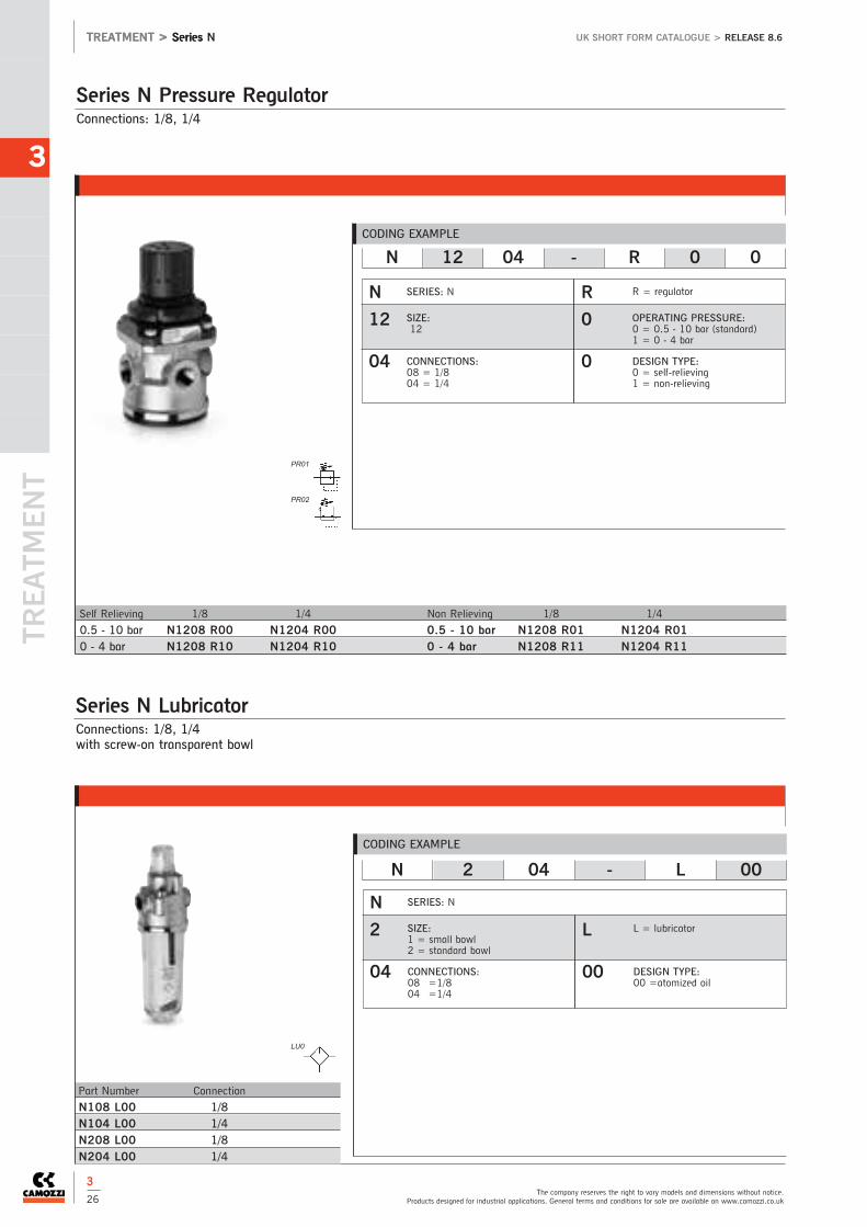
TREATM
ENT
3
The company reserves the right to vary models and dimensions without notice.Products designed for industrial applications. General terms and conditions for sale are available on www.camozzi.co.uk
TREATMENT > Series UK SHORT FORM CATALOGUE > RELEASE 8.6
3
26
Connections: 1/8, 1/4
Series N Pressure Regulator
Self Relieving 1/8 1/4 Non Relieving 1/8 1/4
0.5 - 10 bar N1208 R00 N1204 R00 0.5 - 10 bar N1208 R01 N1204 R010 - 4 bar N1208 R10 N1204 R10 0 - 4 bar N1208 R11 N1204 R11
CODING EXAMPLE
N 12 04 - R 0 0
N 2 04 - L 00
N
12
04
R
0
0
SERIES: N
SIZE:12
CONNECTIONS:08 = 1/8 04 = 1/4
R = regulator
OPERATING PRESSURE:0 = 0.5 - 10 bar (standard)1 = 0 - 4 bar
DESIGN TYPE:0 = self-relieving1 = non-relieving
Connections: 1/8, 1/4with screw-on transparent bowl
Series N Lubricator
Part Number Connection
N108 L00 1/8N104 L00 1/4N208 L00 1/8N204 L00 1/4
CODING EXAMPLE
N
2
04
L
00
SERIES: N
SIZE:1 = small bowl2 = standard bowl
CONNECTIONS:08 =1/804 =1/4
L = lubricator
DESIGN TYPE:00 =atomized oil
TREATMENT > Series N
PR01
PR02
LU0

3
See full catalogue or CD rom for all dimensions.For technical advice contact our sales office or your local Camozzi distributor.
UK SHORT FORM CATALOGUE > RELEASE 8.6
3
27
TREATMENT > Series N
Connections: 1/8, 1/4with screw-on transparent bowl
Series N Filter/Regulator
Semi Auto Drain 1/8 Small Bowl 1/4 Small Bowl 1/8 Standard Bowl 1/4 Standard Bowl
25 micron N108 D00 N104 D00 N208 D00 N204 D005 micron N108 D10 N104 D10 N208 D10 N204 D10
Depressurisation Drain 1/8 Standard Bowl 1/4 Standard Bowl
25 micron N208 D04 N204 D045 micron N208 D14 N204 D14
Depressurisation Drain Protected 1/8 Standard Bowl 1/4 Standard Bowl
25 micron N208 D05 N204 D055 micron N208 D15 N204 D15
Connection 1/8 1/8 Small Bowl 1/4 Small Bowl 1/8 Standard Bowl 1/4 Standard Bowl
25 micron N108 D08 N104 D08 N208 D08 N204 D085 micron N108 D18 N104 D18 N208 D18 N204 D18
CODING EXAMPLE
N 2 04 - D 0 0
N
2
04
D
0
0
SERIES: N
SIZE:1 = small bowl2 = standard bowl
CONNECTIONS:08 =1/804 =1/4
D = filter/regulator
FILTERING ELEMENT:0= 25µm standard1 = 5µm
DRAINING OF CONDENSATE:0= semi-automatic, self-relieving1 = semi-automatic, non-relieving4 = depressurisation, self-relieving5 = depressurisation, protected 8 = connection 1/8,see 3/30
Pressure gauges Ø43 - 53 - 63 mm.Other Pressure Gauges available on request
Pressure Gauges
Part NumberM043-R06M043-R12M053-R12M063-R12
Part NumberM043-P04M043-P06M043-P12M053-P04M053-P06M053-P12M063-P04M063-P06M063-P12
Part NumberM043-F04M043-F06M043-F12M063-F12
FR01
FR02
FR11

TREATM
ENT
3
The company reserves the right to vary models and dimensions without notice.Products designed for industrial applications. General terms and conditions for sale are available on www.camozzi.co.uk
TREATMENT > Series UK SHORT FORM CATALOGUE > RELEASE 8.6
3
28
TREATMENT > Series MX
Part NumberMX2-XMX2-Z**kit with wall fixing screw
Part NumberMX3-XMX3-Z
Part NumberMX2-Y
Part NumberMX3-Y
Rapid Clamp Kit for Series MX - Size 2Kit MX2-X supplied with: 1 rapid clamp, 1 O-ring OR 3125**, 2 hexagonalnuts M5, 2 screws M5x69.Kit MX2-Z supplied with: 1 rapid clamp, 1 O-ring OR 3125**, 1 hexagonalnut M5, 1 screw M5x69, 1 screw M5x85 for wall fixing.
** it can be ordered separately (cod. 160-39-11/19)
Materials: technopolymer clamp, NBR O-ring,zinc-plated stainless steel nuts and screws.
Rapid Clamp Kit for Series MX - Size 3Kit MX3-X supplied with: 1 rapid clamp, 1 O-ring OR 3150 **, 2 squarenuts M6, 2 screws M6x75.Kit MX3-Z supplied with: 1 rapid clamp, 1 O-ring OR 3150 **, 1 squarenut M6, 1 screw M6x75, 1 screw M6x90 for wall fixing.
** it can be ordered separately (cod. C401-F33)
Materials: technopolymer clamp, NBR O-ring,zinc-plated stainless steel nuts and screws.
Rapid Clamp Kit with wall fixing brackets for Series MX -Size 3The kit MX3-Y is supplied with:1 wall rapid clamp, 1 O-ring OR 3150 **,2 square nuts M6, 2 screws M6x75
** it can be also separately ordered (cod. C401-F33)
Materials: technopolymer clamp, NBR O-ring,zinc-plated stainless steel nuts and screws.
Rapid Clamp Kit with wall fixing brackets for Series MX -Size 2The kit MX2-Y is supplied with:1 wall rapid clamp, 1 O-ring OR 3125 **, 2 hexagonalnuts, 2 screws M5x69.
** it can be separately ordered (cod. 160-39-11/19)
Materials: technopolymer clamp, NBR O-ring, zinc-plated stainless steel nuts and screws.
Part NumberMX2-3/8-FLMX2-1/2-FLMX2-3/4-FLMX3-3/4-FLMX3-1-FL
Part NumberMX2-SMX3-S
Fixing bracket for regulators Series MXThe kit is supplied with 1 zinc-plated stainless steel bracket
Terminal Flanges (IN/OUT) for Series MXThe kit is supplied with:- 1 flange INLET side- 1 flange OUTLET side
Materials: painted aluminiumflanges.
Part NumberMX2-3/8-HHMX2-1/2-HHMX2-3/4-HHMX2-3/8-JJ*MX2-1/2-JJ*MX2-3/4-JJ*
Part NumberMX3-3/4-HHMX3-1-HHMX3-3/4-JJ*MX3-1-JJ**kit with wall fixing screw
Part NumberMX2-3/8-KKMX2-1/2-KKMX2-3/4-KK
Part NumberMX3-3/4-KKMX3-1-KK
Rapid clamps kitwith wall fixing brackets + flanges forSeries MX
Rapid clamps kit + flanges for Series MX
Series MX Accessories for FRL

3
See full catalogue or CD rom for all dimensions.For technical advice contact our sales office or your local Camozzi distributor.
UK SHORT FORM CATALOGUE > RELEASE 8.6
3
29
TREATMENT > Series MC, M, N and T
Part Number ConnectionMC104-FL 1/4
Part NumberMC104-ST
Part Number ConnectionMC1-TMF 1/4
Part Number ConnectionMC1-TFF 1/4
Part Number ConnectionMC1-VM 1/4
Part Number ConnectionMC1-VMF 1/4
Part NumberN204-ST
Part NumberC114-ST
Part Number ConnectionC114-ST/1
Part NumberMC1-VMD
Terminal flanges (pair). Series MC (kit A)Complete with: N° 4 screws, N° 2 O-Ring
2 mounting brackets. Series MC (kit B)For 1/4, 3/8 and 1/2. Complete with: N° 4 screws M5
Tie-rod for assembling Series MC (kit C)Male and female tie-rods complete with: N° 2 tie-rods, N° 1 O-Ring
Tie-rod for assembling Series MC (kit D)Female tie-rods complete with: N° 2 tie-rods
Screw for assembling Series MC (kit E)Complete with: N° 2 screws, N° 1 O-Ring
Screw for assembling Series MC (kit F)Complete with: N° 2 male screws, N° 2 female screws, N° 1 O-Ring
Mounting bracket Series NF-L (for 1/8, 1/4).Complete with: N° 2 screws
Mounting bracket. Series MC-M-NR-D (1/8 - 1/4)
Mounting bracket. Series MC-M-N R-D (1/8 - 1/4)
Screw for assembling Series MCF-R-L (for C401)Complete with:NO 2 screws
Part Number20mm padlock
MX Pad lock
Part Number ConnectionC114-ST/2
Mounting bracket. Series MC-M-N R-D (1/8 - 1/4)
Series MC, M, N and T

TREATM
ENT
3
The company reserves the right to vary models and dimensions without notice.Products designed for industrial applications. General terms and conditions for sale are available on www.camozzi.co.uk
TREATMENT > Series UK SHORT FORM CATALOGUE > RELEASE 8.6
3
30
TREATMENT > Series MX, MC and N
Semi-automatic manual drainAutomatic drainDepressurisation drain
Depressurisation drain , protectedConnections: 1/8 (without drain)
Series MX, MC and N Functioning Condensate Drains
Semi-automatic - manual drain
Type 0 and 1
Automatic drain
Type 3
Depressurisation drain
Type 4
Depressurisation drain, protected
Type 5
Connection 1/8(without drain)
Type 8

CONNEC
TION
4
4 > Connection
4 / 2 Technical Data
Super-Rapid Fittings
4 / 3 Series 6000Super-Rapid Fittings For Plastic Tubes
4 / 9 Series 7000 Super-Rapid Compact™ Fittings in Technopolymer
4 / 13 Series 8000 Dual Seal Push-In Fittings
4 / 14 Series X6000Super-Rapid Fittingsin Stainless Steel

4
4 / 19 Series 1000Compression Fittings
Quick-Release Couplings
4 / 29 Series 5000 Quick-Release Couplings
Air Brake Fittings
4 / 30 Series 9000 C-Truck Air Brake Fittings
NPT Fittings
4 / 33 NPT Push-In Fittings and Adaptors
Rapid Fittings
4 / 15 Series 1000Rapid Fittings for Plastic Tubes
Fittings Accessories
4 / 20 Series S2000Pipe Fittings Sprint®
4 / 21 Series 2000Pipe Fittings
4 / 24 316 Stainless SteelPipe Fittings
4 / 26 Brass Hose Tails and Connectors
4 / 27 Aluminium Distribution Manifold Blocks
Compression Fittings
New

Technical Data
CONNEC
TION
4
The company reserves the right to vary models and dimensions without notice.Products designed for industrial applications. General terms and conditions for sale are available on www.camozzi.co.uk
CONNECTION > Technical Data UK SHORT FORM CATALOGUE > RELEASE 8.6
4
2
MediaPush-inCompressed air (brass and technopolymer). Compressed air andwater (stainless steel)Dual SealCompressed air and any fluids compatible with thematerials specified requiring a leak tight seal Push-on, Compression, Pipe Fittings and Quick Release CouplingsCompressed air and other low pressure fluidsC-TruckCompressed air
Tube OptionsPush-inNylon 6, 11, 12, polyurethane, polyethylene and HytrelpolyesterPush-onAs push-in + PVC braidedDual SealNylon 6, 11, 12, polyurethane and Hytrel polyesterCompressionNylon 6, 11, 12 with insert 1320 and annealed copperQuick Release CouplingsNylon, polyurethane, polyethylene, PVC and rubber hoseC-TruckPolyamide (D/d) 4/2, 6/4, 8/6, 10/8, 12/9, 15/12, 16/13and 18/14
MaterialsPush-inBody: Nickel-plated brass (Series 6000)
Technopolymer (Series 7000)Stainless steel 316L (Series X6000)
Push-in Collets: Nickel-plated brass (Series 6000)Nickel-plated brass (Series 7000)
Collet and Body O-rings: NBR (Series 6000)NBR (Series 7000)
Thread Seal: PTFE, NBR, Nylon (Series 6000)NBR (Series 7000)FKM (Series X6000)
Push-onBody: Nickel-plated brass (Series 1000)Body O-rings: NBR Thread Seal: PTFE, Nylon, ALDual Seal Push-onBody and gripper: Nickel-plated brassSeals: NBRCompressionNickel-plated brassPipe FittingsBody: Nickel-plated brass or 316 (CF8M) Stainless SteelThread Seal: PTFE (Series S2000)Quick-Release CouplingsBody: Nickel-plated brass (hardened galvanised steel only for
couplings with a ‘8’ as the third number in the code)Seals: NBRC-TruckBody and collet: BrassLocking nut: brass / zinc-plated steelInsert: brass / technopolymerSeals and protective cap: NBR
Additional OptionsVacuum: All Camozzi fittings and Quick Release Couplingsare suitable for vacuum applications. Check with Camozzisales office for further information.Viton O-rings: Available for most products on requestNPT versions: Available for most products on request
Special RequestsWe offer a comprehensive design service to cater for allyour special needs. If you cannot find what you need in ourcatalogue or you have a special request contact theCamozzi sales office with details of your enquiry.
Assembly Notes for Push-in FittingsTube ends should be cut square and be free from scoringor burrs.The tube should be pushed through the collet and into thefitting until the tube end bottoms out.To release tube, ensure there is no air present and pushthe collet ring towards the body of the fitting and withdrawthe tube.
Assembly Notes for Compression FittingsTube ends should be cut square and concentric. Pass tubethrough tube nut and into olive.Position olive so that it is square against the conical face ofthe body of the fitting.Run nut onto thread and tighten carefully until olive “bites”onto surface of tube. Do not over tighten as this mayresult in tube being crushed and the flow being restricted.The use of a tube insert is recommended for plastic tubes.
Assembly Notes for Push-on FittingsTube ends should be cut square and be free from scoringor burrs.Slide nut over tube.Push the tube onto the nipple until the end reaches theshoulder on the body of the fitting.Screw nut onto thread until finger tight. For additionalsecurity, use spanner to tighten through a quarter turn. Do not over tighten.
Note:Sprint fittings suitable for use in taper applications
NPT versions available for most products on request.
See individual product pages for operating pressures andtemperatures.

Series 6000 Super-Rapid Fittings For Plastic Tubes
4
See full catalogue or CD rom for all dimensions.For technical advice contact our sales office or your local Camozzi distributor.
CONNECTION > Series 6000UK SHORT FORM CATALOGUE > RELEASE 8.6
4
3
Male Stud
S6510 4-1/8
S6510 4-1/4
S6510 5-1/8
S6510 5-1/4
S6510 6-1/8
S6510 6-1/4
S6510 6-3/8
S6510 8-1/8
S6510 8-1/4
S6510 8-3/8
S6510 8-1/2
S6510 10-1/4
S6510 10-3/8
S6510 10-1/2
S6510 12-1/4
S6510 12-3/8
S6510 12-1/2
S6510 14-3/8
S6510 14-1/2
S6510 16-1/2
S6510 16-3/4
Male Stud - Parallel
6512 3-M3O
6512 3-M5*
6512 4-M7-M*
6512 4-1/8-M*Y
6512 6-M7-M*
6512 6-1/8-M*Y
6512 8-1/8-M*Y
6512 10-1/4-M*
Male Stud - Parallel
6512 4-M5
6512 4-M6
6512 4-1/8
6512 4-1/4
6512 5-M5
6512 6-M5
6512 6-1/8
6512 6-1/4
6512 8-1/8
6512 8-1/4
6512 8-3/8
6512 10-1/4
6512 10-3/8
6512 12-1/4
6512 12-3/8
Female Stud
6463 4-M5
6463 4-1/8
6463 5-1/8
6463 6-1/8
6463 6-1/4
6463 8-1/8
6463 8-1/4
6463 10-1/4
Swivel Elbow
S6520 4-1/8
S6520 4-1/4
S6520 5-1/8
S6520 5-1/4
S6520 6-1/8
S6520 6-1/4
S6520 6-3/8
S6520 8-1/8
S6520 8-1/4
S6520 8-3/8
S6520 8-1/2
S6520 10-1/4
S6520 10-3/8
S6520 10-1/2
S6520 12-1/4
S6520 12-3/8
S6520 12-1/2
S6520 14-3/8
S6520 14-1/2
Swivel Elbow - Parallel
6522 3-M3O
6522 3-M5*
Fixed Male Elbow - Taper
S6500 4-1/8
S6500 4-1/4
S6500 5-1/8
S6500 5-1/4
S6500 6-1/8
S6500 6-1/4
S6500 8-1/8
S6500 8-1/4
S6500 8-3/8
S6500 10-1/4
S6500 10-3/8
S6500 12-1/4
S6500 12-3/8
Sprint ®
Note: with O-Ring
Sprint ®
Swivel Elbow - Parallel
6522 4-M5
6522 4-1/8
6522 4-1/4
6522 5-M5
6522 6-M5
6522 6-1/8
6522 6-1/4
6522 8-1/8
6522 8-1/4
6522 8-3/8
6522 10-1/4
6522 10-3/8
6522 12-1/4
6522 12-3/8
Note: with O-Ring
Sprint ®
Tube external diameters: 3, 4, 5, 6, 8, 10, 12, 14, 16 mmThreaded connections: metric (M3, M5, M6, M7), BSP (G1/8, G1/4, G3/8, G1/2, G3/4), BSPT (R1/8, R1/4, R3/8, R1/2)Operating pressure: min -0.9 bar - max 16 bar (see data for tubing used)Operating temperature: Series 6000 Micro: -10˚C - +80˚C. Series 6000: -20˚C - +80˚C (see data for tubing used)
Super-rapid fittings Series 6000 are available in 35 different models.Super-rapid fittings Series 6000 Micro are available in 14 different models.Connection and disconnection of the tube can be repeated several times and can be performed without the use of tools. The extractable internal collet allows the sealing ring (O-ring) to be easily replaced if it is damaged or in case of wear of therubber compound.
O = with mod. 2661 assembled
* = with O-ring assembled
*Y= with O-ring assembledIt can be connected also to valveislands Series Y
Swivel elbowO = with mod. 2661 assembled
* = with O-ring assembled

CONNEC
TION
4
The company reserves the right to vary models and dimensions without notice.Products designed for industrial applications. General terms and conditions for sale are available on www.camozzi.co.uk
CONNECTION > Series 6000 UK SHORT FORM CATALOGUE > RELEASE 8.6
Extended Swivel Elbow
6525 6-1/8
6525 6-1/4
6525 8-1/8
6525 8-1/4
Banjo Fitting - Parallel
6621 3-M3
6621 3-M5
Fixed Male Elbow - Parallel
6501 4-M5
Swivel Branch Tee
S6430 4-1/8
S6430 5-1/8
S6430 5-1/4
S6430 6-1/8
S6430 6-1/4
S6430 8-1/8
S6430 8-1/4
S6430 8-3/8
S6430 10-1/4
S6430 10-3/8
S6430 10-1/2
S6430 12-1/4
S6430 12-3/8
S6430 12-1/2
S6430 14-1/2
Swivel Branch Tee - Parallel
6432 3-M3O
6432 3-M5*
Swivel Branch Tee - Parallel
6432 4-M5
6432 4-1/8
6432 5-M5
6432 6-1/8
6432 6-1/4
6432 8-1/8
6432 8-1/4
6432 8-3/8
6432 10-1/4
6432 10-3/8
6432 12-1/4
6432 12-3/8
Swivel Run Tee
S6440 4-1/8
S6440 5-1/8
S6440 6-1/8
S6440 6-1/4
S6440 8-1/8
S6440 8-1/4
S6440 8-3/8
S6440 10-1/4
S6440 10-3/8
S6440 12-3/8
S6440 14-1/2
Swivel Run Tee - Parallel
6442 3-M3O
6442 3-M5*
Series 6000 Super-Rapid Fittings For Plastic Tubes
4
4
Sprint ® Sprint ®
Sprint ®
Adjustable with mod. 2661assembled
With mod. 2661 assembled
O = with mod. 2661 assembled
* = with O-ring assembled
O = with mod. 2661 assembled
* = with O-ring assembled

4
See full catalogue or CD rom for all dimensions.For technical advice contact our sales office or your local Camozzi distributor.
CONNECTION > Series 6000UK SHORT FORM CATALOGUE > RELEASE 8.6
Series 6000 Super-Rapid Fittings For Plastic Tubes
Swivel Run Tee - Parallel
6442 4-M5
6442 4-1/8
6442 5-M5
6442 6-1/8
6442 6-1/4
6442 8-1/8
6442 8-1/4
6442 8-3/8
6442 10-1/4
6442 10-3/8
6442 12-1/4
6442 12-3/8
Swivel Y Connector - Parallel
6452 3-M3O
6452 3-M5*
Fixed Y Connector - Parallel
6451 4-M5*
6451 6-M5*
Swivel Y Connector
S6450 4-1/8
S6450 6-1/8
S6450 8-1/8
S6450 8-1/4
Single Banjo
6622 4-M5
6622 4-1/8
6622 6-1/8
6622 6-1/4
6622 8-1/8
6622 8-1/4
6622 10-1/4
Double Banjo
6632 4-1/8
6632 6-1/8
6632 6-1/4
6632 8-1/8
6632 8-1/4
6632 10-1/4
Double Banjo Ring Connector
6620 4-M5
6620 4-1/8
6620 6-1/8
6620 6-1/4
6620 8-1/8
6620 8-1/4
Banjo Bolts
1631 01...
1631 02...
1631 03...
Single Banjo Ring
6610 4-M5
6610 4-M6•
6610 4-1/8
6610 5-M5
6610 5-M6•
6610 5-1/8
6610 6-M5
6610 6-M6•
6610 6-1/8
6610 6-1/4
6610 8-1/8
6610 8-1/4
6610 8-3/8
6610 10-1/4*
6610 10-3/8*
6610 12-1/2*
4
5
Note: with O-Ring
Sprint ®
Note: with O-Ring
Note: with O-Ring
•Banjo ring connector required for M5 versionsof SCU, MCO, SVU, MVU, SCO and MCO
* assembly required with Part Number 1635
Assembly with mod. 1631, 1635
O = with mod. 2661 assembled
* = with O-ring assembled
* = non swivel model with mod.2661 assembled
See page 4/17

CONNEC
TION
4
The company reserves the right to vary models and dimensions without notice.Products designed for industrial applications. General terms and conditions for sale are available on www.camozzi.co.uk
CONNECTION > Series 6000 UK SHORT FORM CATALOGUE > RELEASE 8.6
Series 6000 Super-Rapid Fittings For Plastic Tubes
Equal Tube Elbow
6550 4
6550 5
6550 6
6550 8
6550 10
6550 12
6550 14
Equal Tube Tee
6540 3
Equal Tube Tee
6540 4
6540 5
6540 6
6540 8
6540 10
6540 12
6540 14
Part Number
S6110 6-1/8
S6110 6-1/4
S6110 8-1/8
S6110 8-1/4
S6110 8-3/8
S6110 10-1/4
S6110 10-3/8
S6110 10-1/2
S6110 12-1/4
S6110 12-3/8
S6110 12-1/2
Bulk Head Connector
6590 3
Equal Tube Elbow
6550 3
4
6
Bulkhead Connector
6590 4
6590 5
6590 6
6590 8
6590 10
6590 12
6590 14
Stem Adaptor
6811 4-M5*
6811 4-1/8
6811 5-1/8
6811 5-1/4
6811 6-1/8
6811 6-1/4
6811 8-1/8
6811 8-1/4
6811 10-1/4
6811 10-3/8
6811 12-3/8
6811 14-1/2
Sprint ®
*Note: with O-Ring
Tube to Tube Connector
6580 4
6580 5
6580 6
6580 8
6580 10
6580 12
6580 14
Reduction
6580 6-4
6580 8-6
6580 10-8
6580 12-10
Part Number
6593 6-1/8
6593 6-1/4
6593 8-1/8
6593 8-1/4
6593 10-3/8
Tube to Tube Connector
6580 3

4
See full catalogue or CD rom for all dimensions.For technical advice contact our sales office or your local Camozzi distributor.
CONNECTION > Series 6000UK SHORT FORM CATALOGUE > RELEASE 8.6
Equal Tube Cross Connector
6600 4
6600 5
6600 6
6600 8
6600 10
6600 12
Equal Tube Y
6560 3
Equal Tube Y
6560 4
6560 6
6560 8
6560 10
Press Fit Cartridge
6700 3
Press Fit Cartridge
6700 4
6700 5
6700 6
6700 8
6700 10
Tube Blanking Cap
6750 4
6750 6
6750 8
6750 10
6750 12
Tube Stem Increaser
6850 6-4
6850 8-6
Tube Stem Reducer
6800 3-4
4
7
Series 6000 Super-Rapid Fittings For Plastic Tubes
Tube Stem Reducer
6800 4-5
6800 4-6
6800 4-8
6800 5-6
6800 5 -8
6800 6-8
6800 6-10
6800 6-12
6800 8-10
6800 8-12
6800 10-12
6800 10-14
6800 12-14
Straight Stem
6950 4
6950 6
6950 8
6950 10
6950 12
6950 14
Tube to Stem Elbow
6555 4-4
6555 6-6
6555 8-8
6555 10-10
Dust Cover
6708 4
6708 5
6708 6
6708 8
6708 10
6708 12
6708 14

CONNEC
TION
4
The company reserves the right to vary models and dimensions without notice.Products designed for industrial applications. General terms and conditions for sale are available on www.camozzi.co.uk
CONNECTION > Series 6000 UK SHORT FORM CATALOGUE > RELEASE 8.6
Series 6000 Super-Rapid Fittings For Plastic Tubes
Blanking Plug
6900 3
Blanking Plug (plastic)
6900 4
6900 5
6900 6
6900 8
6900 10
6900 12
6900 14
Part Number
SP
For Tubing
See 10 (Tubing)
For Banjo Bolts
See page 4/17
4
8
The set includes keys to disconnecttubes with diameters between 4 and12mm

4
See full catalogue or CD rom for all dimensions.For technical advice contact our sales office or your local Camozzi distributor.
CONNECTION > Series 7000UK SHORT FORM CATALOGUE > RELEASE 8.6
4
9
Tube external diameters: 4, 6, 8, 10, 12, 16mmConnections: metric (M5, M7), BSP (G1/8, G1/4, G3/8, G1/2, G3/4)Operating pressure: min -0.9 bar - max 16 bar (see data for tubing used)Operating temperature: -20˚C - +60˚C (see data for tubing used)
These models have been released in technopolymer, maintaining the same technical characteristics as the existing Camozzifittings range.Lightweight, adaptable and they allow for easy maintenance of the collet and the internal seal.All materials, with the exception of the internal seals, can easily be recycled.
Series 7000 Super-Rapid Compact TM Fittings in Technopolymer
Swivel Elbow
7522 4-M5
7522 4-M7
7522 4-1/8
7522 4-1/4
7522 6-M5
7522 6-M7
7522 6-1/8
7522 6-1/4
7522 8-1/8
7522 8-1/4
7522 8-3/8
7522 10-1/4
7522 10-3/8
7522 10-1/2
7522 12-1/4
7522 12-3/8
7522 12-1/2
7522 16-1/2
7522 16-3/4
Long Swivel Elbow
7526 4-1/8
7526 6-1/8
7526 6-1/4
7526 8-1/8
7526 8-1/4
Swivel Run Tee
7442 4-1/8
7442 6-1/8
7442 6-1/4
7442 8-1/8
7442 8-1/4
7442 8-3/8
7442 10-1/4
7442 10-3/8
7442 12-3/8
7442 12-1/2
7442 16-1/2*
7442 16-3/4*
Swivel Branch Tee
7432 4-M5
7432 4-1/8
7432 6-M5
7432 6-1/8
7432 6-1/4
7432 8-1/8
7432 8-1/4
7432 8-3/8
7432 10-1/4
7432 10-3/8
7432 12-1/4
7432 12-3/8
7432 12-1/2
7432 16-1/2
7432 16-3/4
Swivel Tee Reducer
7542 6-4-1/8
7542 6-4-1/4
7542 8-6-1/8
7542 8-6-1/4
7542 10-8-1/4
7542 10-8-3/8
Male Y
7562 4-1/8
7562 6-1/8
7562 6-1/4
7562 8-1/8
7562 8-1/4
7562 10-1/4
7562 10-3/8
Male Double Y
7572 4-1/8
7572 4-1/4
7572 6-1/8
7572 6-1/4
Swivel Single Banjo
7622 4-1/8
7622 6-1/8
7622 6-1/4
7622 8-1/8
7622 8-1/4
7622 10-1/4
7622 10-3/8
7622 12-3/8
*model without mounting holes

4
The company reserves the right to vary models and dimensions without notice.Products designed for industrial applications. General terms and conditions for sale are available on www.camozzi.co.uk
CONNECTION > Series 7000 UK SHORT FORM CATALOGUE > RELEASE 8.6
4
10
Series 7000 Super-Rapid Compact Fittings in Technopolymer
Swivel Double Banjo
7652 4-1/8
7652 6-1/8
7652 6-1/4
7652 8-1/8
7652 8-1/4
7652 10-1/4
7652 10-3/8
Single Banjo
7610 4-1/8
7610 6-1/8
7610 6-1/4
7610 8-1/8
7610 8-1/4
7610 10-1/4
7610 10-3/8
7610 12-3/8
Double Banjo
7640 4-1/8
7640 6-1/8
7640 6-1/4
7640 8-1/8
7640 8-1/4
7640 10-1/4
Double Banjo Stem
7632 02-1/8
7632 02-1/4
7632 02-3/8
Triple Banjo Stem
7632 03-1/8
7632 03-1/4
Double Single Banjo
7612 02-4-1/8
7612 02-6-1/8
7612 02-6-1/4
7612 02-8-1/8
7612 02-8-1/4
7612 02-10-1/4
7612 02-10-3/8
7612 02-12-3/8
Triple Single Banjo
7612 03-4-1/8
7612 03-6-1/8
7612 03-6-1/4
7612 03-8-1/8
7612 03-8-1/4
7612 03-10-1/4
Double Double Banjo
7642 02-4-1/8
7642 02-6-1/8
7642 02-6-1/4
7642 02-8-1/8
7642 02-8-1/4
7642 02-10-1/4
Reducer
7800 4-6
7800 4-8
7800 6-8
7800 6-10
7800 6-12
7800 8-10
7800 8-12
7800 10-12
7800 10-14
Junction Elbow
7555 4-4
7555 6-6
7555 8-8
7555 10-10
7555 12-12
Union Connector
7580 4
7580 6
7580 8
7580 10
7580 12
Triple Double Banjo
7642 03-4-1/8
7642 03-6-1/8
7642 03-6-1/4
7642 03-8-1/8
7642 03-8-1/4
7642 03-10-1/4
Assembly with adjustable fittings Mod. 7610, 7640
Assembly with adjustable fittings Mod. 7610, 7640
Assembly with Mod. 7632 02, 7632 03
Assembly with Mod. 7632 02, 7632 03
CONNEC
TION

4
See full catalogue or CD rom for all dimensions.For technical advice contact our sales office or your local Camozzi distributor.
CONNECTION > Series 7000UK SHORT FORM CATALOGUE > RELEASE 8.6
4
11
Series 7000 Super-Rapid Compact Fittings in Technopolymer
Elbow Connector
7550 4
7550 6
7550 8
7550 10
7550 12
7550 16
Tee Connector
7540 4
7540 5
7540 6
7540 8
7540 10
7540 12
7540 16
Multi Tee Reducer
7545 6-4
7545 8-6
7545 10-8
Y Reducer
7560 4
7560 6
7560 8
7560 10
7560 6-4
7560 8-6
7560 10-8
Double Y Reducer
7575 6-4
7575 8-6
Plastic Junction
7950 4
7950 6
7950 8
7950 10
7950 12
For Super-Rapid Fittings
See 4/3 - 4/8
For Tubing
See 10 (Tubing)

Tube external diameters: 4 - 6 - 8 mm (Ø 10 and 12mm available on request)Connections: BSP (G1/8, G1/4)Operating pressure: min -0.9 bar - max 60 bar (see data for tubing used)Operating temperature: -20˚C - +80˚C
The Camozzi range of dual seal super rapid push in fittings are designed to assist with the assembly of high pressure fluidsystems up to 60 bar.For technical specifications and assembly notes see page 4/2
Series 8000 Dual Seal Push-In Fittings
4
See full catalogue or CD rom for all dimensions.For technical advice contact our sales office or your local Camozzi distributor.
CONNECTION > Series 8000UK SHORT FORM CATALOGUE > RELEASE 8.6
Swivel Elbow
8522 4-1/8
8522 6-1/8
8522 6-1/4
8522 8-1/8
8522 8-1/4
Swivel Branch Tee
8432 4-1/8
8432 6-1/8
8432 8-1/8
8432 8-1/4
Tube to Tube Connector
8580 4
8580 6
8580 8
Equal Tube Elbow
8550 4
8550 6
8550 8
Equal Tube Tee
8540 4
8540 6
8540 8
For NPT Fittings
See Page 4/33
For Tubing
See 10 (Tubing)
4
13
Note: with O-Ring
Note: with O-Ring
Note: with O-Ring
Male Stud
8512 4-1/8
8512 6-1/8
8512 6-1/4
8512 8-1/8
8512 8-1/4
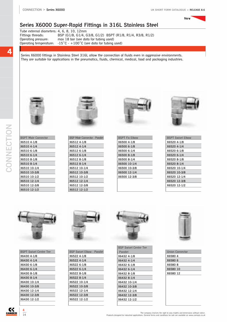
Tube external diameters: 4, 6, 8, 10, 12mmFittings threads: BSP (G1/8, G1/4, G3/8, G1/2) BSPT (R1/8, R1/4, R3/8, R1/2)Operating pressure: max 18 bar (see data for tubing used)Operating temperature: -15˚C - +100˚C (see data for tubing used)
Series X6000 fittings in Stainless Steel 316L allow the connection of fluids even in aggressive environments.They are suitable for applications in the pneumatics, fluids, chemical, medical, food and packaging industries.
Series X6000 Super-Rapid Fittings in 316L Stainless Steel
CONNEC
TION
4
The company reserves the right to vary models and dimensions without notice.Products designed for industrial applications. General terms and conditions for sale are available on www.camozzi.co.uk
CONNECTION > Series X6000 UK SHORT FORM CATALOGUE > RELEASE 8.6
4
14
BSP Male Connector - Parallel
X6512 4-1/8
X6512 4-1/4
X6512 6-1/8
X6512 6-1/4
X6512 8-1/8
X6512 8-1/4
X6512 10-1/4
X6512 10-3/8
X6512 10-1/2
X6512 12-1/4
X6512 12-3/8
X6512 12-1/2
BSPT Fix Elbow
X6500 4-1/8
X6500 6-1/8
X6500 6-1/4
X6500 8-1/8
X6500 8-1/4
X6500 10-1/4
X6500 10-3/8
X6500 12-1/4
X6500 12-3/8
BSPT Swivel Elbow
X6520 4-1/8
X6520 4-1/4
X6520 6-1/8
X6520 6-1/4
X6520 8-1/8
X6520 8-1/4
X6520 10-1/4
X6520 10-3/8
X6520 12-1/4
X6520 12-3/8
X6520 12-1/2
BSPT Male Connector
X6510 4-1/8
X6510 4-1/4
X6510 6-1/8
X6510 6-1/4
X6510 8-1/8
X6510 8-1/4
X6510 10-1/4
X6510 10-3/8
X6510 10-1/2
X6510 12-1/4
X6510 12-3/8
X6510 12-1/2
BSP Swivel Elbow - Parallel
X6522 4-1/8
X6522 4-1/4
X6522 6-1/8
X6522 6-1/4
X6522 8-1/8
X6522 8-1/4
X6522 10-1/4
X6522 10-3/8
X6522 12-1/4
X6522 12-3/8
X6522 12-1/2
BSP Swivel Centre Tee
- Parallel
X6432 4-1/8
X6432 4-1/4
X6432 6-1/8
X6432 6-1/4
X6432 8-1/8
X6432 8-1/4
X6432 10-1/4
X6432 10-3/8
X6432 12-1/4
X6432 12-3/8
X6432 12-1/2
Union Connector
X6580 4
X6580 6
X6580 8
X6580 10
X6580 12
BSPT Swivel Centre Tee
X6430 4-1/8
X6430 4-1/4
X6430 6-1/8
X6430 6-1/4
X6430 8-1/8
X6430 8-1/4
X6430 10-1/4
X6430 10-3/8
X6430 12-1/4
X6430 12-3/8
X6430 12-1/2
New

Tee Connector
X6540 4
X6540 6
X6540 8
X6540 10
X6540 12
Bulkhead Union Connector
X6590 4
X6590 6
X6590 8
X6590 10
X6590 12
Reducer Tube/Stem
X6800 4-6
X6800 4-8
X6800 6-8
X6800 6-10
X6800 6-12
X6800 8-10
X6800 8-12
X6800 10-12
Elbow Connector
X6550 4
X6550 6
X6550 8
X6550 10
X6550 12
4
See full catalogue or CD rom for all dimensions.For technical advice contact our sales office or your local Camozzi distributor.
CONNECTION > Series X6000 and Series 1000UK SHORT FORM CATALOGUE > RELEASE 8.6
Series X6000 Super-rapid Fittings
4
15
Male Stud - Taper
1510 5/3-1/8
1510 6/4-1/8
1510 6/4-1/4
1510 6/4-3/8
1510 6/4-1/2
1510 6/4-M12x1.25
1510 8/6-1/8
1510 8/6-1/4
1510 8/6-3/8
1510 8/6-1/2
1510 10/8-1/8
1510 10/8-1/4
1510 10/8-3/8
1510 10/8-1/2
1510 12/10-3/8
1510 12/10-1/2
1510 15/12.5-1/2
1511 8/6-1/4
1511 8/6-3/8
1511 10/8-1/8
1511 10/8-1/4
1511 10/8-3/8
1511 10/8-1/2
1511 12/10-3/8
1511 12/10-1/2
1511 15/12.5-1/2
Sprint ®
Tube external diameters: 5/3, 6/4, 8/6, 10/8, 12/10, 15/12.5mmConnections: metric (M5, M6, M12x1, M12x1.25), BSP (G1/8, G1/4, G3/8, G1/2), BSPT (R1/8, R1/4, R3/8, R1/2)Operating pressure: the nominal pressure of the fittings is always higher than the pressure of the tube Operating temperature: (see data for tubing used)
The Camozzi range of rapid push-on fittings are designed to assist with the assembly of fluid power components andsystems.For technical specifications and assembly notes see page 4/2
Series 1000 Rapid Push-On Fittings For Plastic Tubes
* With O-Ring assembled
Male Stud - Parallel
1511 5/3-M5*
1511 5/3-M6*
1511 5/3-1/8
1511 6/4-M5*
1511 6/4-M6*
1511 6/4-1/8
1511 6/4-1/4
1511 6/4-3/8
1511 8/6-1/8
New

CONNEC
TION
4
The company reserves the right to vary models and dimensions without notice.Products designed for industrial applications. General terms and conditions for sale are available on www.camozzi.co.uk
CONNECTION > Series 1000 UK SHORT FORM CATALOGUE > RELEASE 8.6
Series 1000 Rapid Push-On Fittings For Plastic Tubes
Male Stud Swivel
1560 6/4-1/8
1560 6/4-1/4
1560 8/6-1/8
1560 8/6-1/4
1560 10/8-1/4
1560 10/8-3/8
1560 12/10-3/8
Female Stud
1463 5/3-1/8
1463 6/4-1/8
1463 6/4-1/4
1463 6/4-3/8
1463 8/6-1/8
1463 8/6-1/4
1463 8/6-3/8
1463 10/8-1/8
1463 10/8-1/4
1463 10/8-3/8
1463 10/8-1/2
1463 12/10-3/8
Swivel Elbow - Parallel
1541 6/4-1/8
1541 6/4-1/4
1541 8/6-1/8
1541 8/6-1/4
1541 10/8-1/4
Fixed Stud Elbow - Parallel
1501 5/3-M5
Fixed Female Elbow
1493 6/4-1/8
1493 6/4-1/4
1493 8/6-1/8
1493 8/6-1/4
1493 10/8-1/4
1493 12/10-3/8
Swivel Branch Tee
1431 6/4-1/8
1431 6/4-1/4
1431 8/6-1/8
1431 8/6-1/4
1431 10/8-1/4
Fixed Branch Tee - Taper
1410 5/3-1/8
1410 6/4-1/8
1410 6/4-1/4
1410 8/6-1/8
1410 8/6-1/4
1410 10/8-1/8
1410 10/8-1/4
1410 10/8-3/8
1410 10/8-1/2
1410 12/10-3/8
1410 12/10-1/2
1410 15/12.5-1/2
Fixed Run Tee - Taper
1420 5/3-1/8
1420 6/4-1/8
1420 6/4-1/4
1420 8/6-1/8
1420 8/6-1/4
1420 10/8-1/8
1420 10/8-1/4
Fixed Male Elbow - Taper
1500 5/3-1/8
1500 6/4-1/8
1500 6/4-1/4
1500 6/4-3/8
1500 6/4-M12x1.25
1500 8/6-1/8
1500 8/6-1/4
1500 8/6-3/8
1500 8/6-1/2
1500 10/8-1/8
1500 10/8-1/4
1500 10/8-3/8
1500 10/8-1/2
1500 12/10-3/8
1500 12/10-1/2
1500 15/12.5-1/2
Note: with 2661 Nylon Ring
Sprint ®
Sprint ®
Sprint ®
4
16

4
See full catalogue or CD rom for all dimensions.For technical advice contact our sales office or your local Camozzi distributor.
CONNECTION > Series 1000UK SHORT FORM CATALOGUE > RELEASE 8.6
Series 1000 Rapid Push-On Fittings For Plastic Tubes
Banjo Assemblies
1521 5/3-M5
1521 5/3-1/8
1521 6/4-M5
1521 6/4-1/8
1521 6/4-1/4
1521 6/4-3/8
1521 8/6-1/8
1521 8/6-1/4
1521 8/6-3/8
Double Banjo Ring Connector
1620 6/4-M5
1620 6/4-1/8
1620 6/4-1/4
1620 8/6-1/8
1620 8/6-1/4
Banjo Assemblies
1525 6/4-1/8
1525 6/4-1/4
1525 6/4-3/8
1525 8/6-1/8
1525 8/6-1/4
1525 8/6-3/8
1525 10/8-1/8
1525 10/8-1/4
1525 10/8-3/8
1525 10/8-1/2
1525 12/10-3/8
1525 12/10-1/2
1525 15/12.5-1/2
Single Banjo Ring Connector
1610 5/3-M5
1610 5/3-M6•
1610 5/3-1/8
1610 6/4-M5
1610 6/4-M6•
1610 6/4-1/8
1610 6/4-1/4
1610 6/4-3/8
1610 8/6-1/8
1610 8/6-1/4
1610 8/6-3/8
1610 10/8-1/8*
1610 10/8-1/4*
1610 10/8-3/8*
1610 10/8-1/2*
1610 12/10-3/8*
1610 12/10-1/2*
1610 15/12.5-1/2*
Note: with 2661 Nylon Ring Note: with 2661 Nylon Ring
• Banjo ring connector required for M5versions of SCU, MCO, SVU, MVU, SCOand MCO
* assembly required with Part Number 1635
4
17
Assembly with Mod. 1631-1635
Single Banjo Bolt (up to & incl 8mm)
1631 01-M5*
1631 01-1/8
1631 01-1/4
1631 01-3/8
1631 01-1/2
Single Banjo Bolt (8mm & above)
1635 01-1/8
1635 01-1/4
1635 01-3/8
1635 01-1/2
1635 01-M12x1.25*
1635 01-M12x1.5*
Double Banjo Bolt (up to & incl 8mm)
1631 02-1/8
1631 02-1/4
1631 02-3/8
Double Banjo Bolt(8mm & above)
1635 02-1/8
1635 02-1/4
1635 02-3/8
1635 02-1/2
Triple Banjo Bolt (up to & incl 8mm)
1631 03-1/8
1631 03-1/4
1631 03-3/8
For assembly with banjo fittingsMod. 6610, 6620, 1610, 1620,1170, 2023
For assembly with banjo fittings Mod.6610, 6620, 1610, 1620, 1170, 2023*Assembled with 1/4 banjo fittings
For assembly with banjo fittings Mod.6610, 6620, 1610, 1620, 1170,2023
For assembly with banjo fittings Mod.6610, 6620, 1610, 1620, 1170,2023
For assembly with banjo fittings Mod.6610, 6620, 1610, 1620, 1170,2023

CONNEC
TION
4
The company reserves the right to vary models and dimensions without notice.Products designed for industrial applications. General terms and conditions for sale are available on www.camozzi.co.uk
CONNECTION > Series 1000 UK SHORT FORM CATALOGUE > RELEASE 8.6
Series 1000 Rapid Push-On Fittings For Plastic Tubes
Equal Tube Cross
1600 6/4
1600 8/6
Tube Stem Adaptor
1470 6/4-6
1470 8/6-8
Plastic Blanking Cap
1710 5/3
1710 6/4
1710 8/6
1710 10/8
1710 12/10
Aluminium Washer
2651 1/8
2651 1/4
2651 3/8
2651 1/2
2651 1
Nylon Washer
2661 M3
2661 M5
2661 M6
2661 1/8
2661 1/4
2661 3/8
2661 1/2
Nylon Spacer 5mm
2665 1/8
2665 1/4
2665 3/8
2665 1/2
Nylon Spacer 9mm
2669 1/8
2669 1/4
2669 3/8
2669 1/2
Tube Nut
1703 5/3-M7x0.75
1703 6/4-M8x0.75
1703 6/4-M10x1
1703 8/6-M12x1
1703 10/8-M14x1
1703 12/10-M16x1
1703 15/12.5-M20x1
Anti Kink Tube Nut
1723 6/4-M10x1
1723 8/6-M12x1
1723 10/8-M14x1
1723 12/10-M16x1
1723 15/12.5-M20x1
Useful for blanking off ortesting purposes
4
18
Tube to Tube Connector
1580 5/3
1580 6/4
1580 8/6-6/4
1580 8/6
1580 10/8-6/4
1580 10/8
1580 12/10
1580 15/12.5
Bulkhead Tube Connector
1590 5/3
1590 6/4-5/3
1590 6/4
1590 8/6-6/4
1590 8/6
1590 10/8
1590 12/10
Equal Tube Elbow
1550 6/4
1550 8/6
1550 10/8
1550 12/10
1550 15/12.5
Equal Tube Tee
1540 5/3
1540 6/4
1540 8/6-6/4
1540 8/6
1540 10/8-6/4
1540 10/8-8/6
1540 10/8
1540 12/10
1540 15/12.5

Tube OD 4 - 6 - 8 - 10 - 12Connections: 1/8, 1/4, 3/8, 1/2.Operating pressure: max 40 bar (see data for tubing used)Operating temperature: -20˚C - +100˚C (see data for tubing used)
The Camozzi range of compression fittings are designed to assist with the assembly of fluid power components and systems.For technical specifications and assembly notes see 4/2
Series 1000 Compression Fittings
4
See full catalogue or CD rom for all dimensions.For technical advice contact our sales office or your local Camozzi distributor.
CONNECTION > Series 1000UK SHORT FORM CATALOGUE > RELEASE 8.6
Female Stud
1063 4-1/8
1063 6-1/8
1063 6-1/4
1063 8-1/8
1063 8-1/4
Fixed Male Elbow - Taper
1020 4-1/8
1020 6-1/8
1020 6-1/4
1020 8-1/8
1020 8-1/4
1020 8-3/8
1020 10-1/4
1020 10-3/8
1020 10-1/2
1020 12-1/4
1020 12-3/8
1020 12-1/2
Fixed Female Elbow
1093 4-1/8
1093 6-1/8
1093 6-1/4
1093 8-1/8
1093 8-1/4
Fixed Branch Tee - Taper
1000 4-1/8
1000 6-1/8
1000 8-1/4
1000 10-1/4
Fixed Run Tee - Taper
1010 4-1/8
1010 6-1/8
1010 8-1/4
1010 10-1/4
Tube to Tube Connector
1230 4
1230 6
1230 8
1230 10
1230 12
Bulkhead Connector
1250 4
1250 6
1250 8
1250 10
Equal Tube Elbow
1220 4
1220 6
1220 8
1220 10
1220 12
Equal Tube Tee
1210 4
1210 6
1210 8
1210 10
1210 12
Single Banjo Ring Connector
1170 6-1/8
1170 6-1/4
1170 8-1/8*
Tube Nut
1303 4-1/8
1303 6-1/8
1303 8-1/4
1303 10-3/8
1303 12-M18x1.5
Male Stud - Taper
1050 4-1/8
1050 6-1/8
1050 6-1/4
1050 8-1/8
1050 8-1/4
1050 8-3/8
1050 10-1/4
1050 10-3/8
1050 10-1/2
1050 12-1/4
1050 12-3/8
1050 12-1/2
* assembly required with PartNumber 1635
4
19

CONNEC
TION
4
The company reserves the right to vary models and dimensions without notice.Products designed for industrial applications. General terms and conditions for sale are available on www.camozzi.co.uk
CONNECTION > Series S2000 UK SHORT FORM CATALOGUE > RELEASE 8.6
Compression Fittings
Olive
1310 4
1310 6
1310 8
1310 10
1310 12-M18*
*biconical
Tube Insert
1320 4
1320 6
1320 8
1320 10
Swivel Adaptor
2541 1/8-1/8
2541 1/4-1/4
2541 3/8-3/8
Male Elbow - Taper
S2010 1/8
S2010 1/4
S2010 3/8
S2010 1/2
Male/Female Elbow - Taper
S2020 1/8-1/8
S2020 1/4-1/4
S2020 3/8-3/8
S2020 1/2-1/2
Female Run Tee - Taper
S2050 1/8-1/8
S2050 1/4-1/4
S2050 3/8-3/8
S2050 1/2-1/2
Nipple - Taper
S2500 1/8
S2500 1/4
S2500 3/8
S2500 1/2
Reducing Nipple - Taper
S2510 1/8-1/4
S2510 1/8-3/8
S2510 1/4-3/8
S2510 1/4-1/2
S2510 3/8-1/2
Adaptor - Taper
S2520 1/8-1/8
S2520 1/8-1/4
S2520 1/8-3/8
S2520 1/4-1/4
S2520 1/4-3/8
S2520 1/4-1/2
S2520 3/8-3/8
S2520 3/8-1/2
S2520 1/2-1/2
Reducing Bush - Taper
S2530 1/4-1/8
S2530 3/8-1/8
S2530 1/2-1/8
S2530 3/8-1/4
S2530 1/2-1/4
S2530 1/2-3/8
Sprint ® Sprint ® Sprint ® Sprint ®
Sprint ® Sprint ® Sprint ®
Connections: BSP (G1/8, G1/4, G3/8, G1/2) BSPT (R1/8, R1/4, R3/8, R1/2)Operating pressure: 40 barOperating temperature: -40˚C - +120˚C
The more popular versions of the Camozzi Pipe Fittings are now available with the unique Camozzi Sprint ® sealing system.For technical specifications and assembly notes see page 4/2
Series S2000 Pipe Fittings Sprint®
4
20
Sprint ®
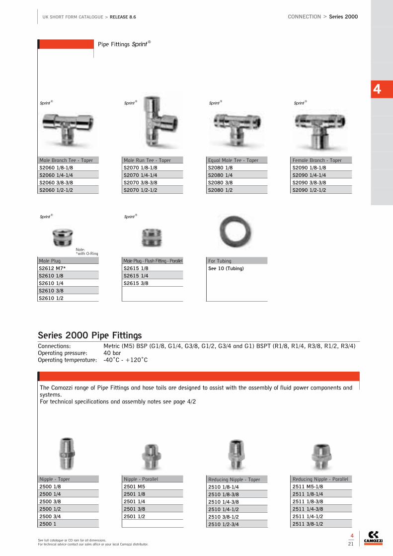
4
See full catalogue or CD rom for all dimensions.For technical advice contact our sales office or your local Camozzi distributor.
CONNECTION > Series 2000UK SHORT FORM CATALOGUE > RELEASE 8.6
Pipe Fittings Sprint®
Male Branch Tee - Taper
S2060 1/8-1/8
S2060 1/4-1/4
S2060 3/8-3/8
S2060 1/2-1/2
Male Run Tee - Taper
S2070 1/8-1/8
S2070 1/4-1/4
S2070 3/8-3/8
S2070 1/2-1/2
Equal Male Tee - Taper
S2080 1/8
S2080 1/4
S2080 3/8
S2080 1/2
Female Branch - Taper
S2090 1/8-1/8
S2090 1/4-1/4
S2090 3/8-3/8
S2090 1/2-1/2
Male Plug
S2612 M7*
S2610 1/8
S2610 1/4
S2610 3/8
S2610 1/2
Male Plug - Flush Fitting - Parallel
S2615 1/8
S2615 1/4
S2615 3/8
For Tubing
See 10 (Tubing)
Nipple - Taper
2500 1/8
2500 1/4
2500 3/8
2500 1/2
2500 3/4
2500 1
Nipple - Parallel
2501 M5
2501 1/8
2501 1/4
2501 3/8
2501 1/2
Reducing Nipple - Taper
2510 1/8-1/4
2510 1/8-3/8
2510 1/4-3/8
2510 1/4-1/2
2510 3/8-1/2
2510 1/2-3/4
Reducing Nipple - Parallel
2511 M5-1/8
2511 1/8-1/4
2511 1/8-3/8
2511 1/4-3/8
2511 1/4-1/2
2511 3/8-1/2
Sprint ® Sprint ® Sprint ® Sprint ®
Sprint ® Sprint ®
Connections: Metric (M5) BSP (G1/8, G1/4, G3/8, G1/2, G3/4 and G1) BSPT (R1/8, R1/4, R3/8, R1/2, R3/4)Operating pressure: 40 barOperating temperature: -40˚C - +120˚C
The Camozzi range of Pipe Fittings and hose tails are designed to assist with the assembly of fluid power components andsystems.For technical specifications and assembly notes see page 4/2
Series 2000 Pipe Fittings
4
21
Note: *with O-Ring

CONNEC
TION
4
The company reserves the right to vary models and dimensions without notice.Products designed for industrial applications. General terms and conditions for sale are available on www.camozzi.co.uk
CONNECTION > Series 2000 UK SHORT FORM CATALOGUE > RELEASE 8.6
4
22
Series 2000 Pipe Fittings
Adaptor - Taper
2520 1/8-1/8
2520 1/8-1/4
2520 1/8-3/8
2520 1/4-1/4
2520 1/4-3/8
2520 1/4-1/2
2520 3/8-3/8
2520 3/8-1/2
2520 1/2-1/2
Adaptor - Parallel
2521 M5-1/8
2521 1/8-1/8
2521 1/8-1/4
2521 1/8-3/8
2521 1/4-1/4
2521 1/4-3/8
2521 1/4-1/2
2521 3/8-3/8
2521 3/8-1/2
2521 1/2-1/2
Extension Piece - Parallel
2525 1/8-16
2525 1/8-36
2525 1/4-27
2525 1/4-43
Reducing Bush - Taper
2530 1/4-1/8
2530 3/8-1/8
2530 1/2-1/8
2530 3/8-1/4
2530 1/2-1/4
2530 1/2-3/8
2530 3/4-3/8
2530 3/4-1/2
2530 1-1/2
Reducing Bush - Parallel
2531 1/8-M5
2531 1/4-1/8
2531 3/8-1/8
2531 3/8-1/4
2531 1/2-1/8
2531 1/2-1/4
2531 1/2-3/8
Female Connector
2543 M5
2543 1/8
2543 1/4
2543 3/8
2543 1/2
Female Reducer
2553 M5-1/8
2553 1/8-1/4
2553 1/8-3/8
2553 1/8-1/2
2553 1/4-3/8
2553 1/4-1/2
2553 3/8-1/2
Blanking Plug - Parallel
2611 M5
2611 1/8
2611 1/4
2611 3/8
2611 1/2
2611 1
Blanking Plug - Taper
2610 3/4
Blanking Nut - Parallel
2613 1/8
2613 1/4
2613 3/8
2613 1/2
Hose Tail - Parallel
2601 2-M5
2601 4.5-M5
2601 7-1/8
2601 7-1/4
2601 8-1/8
2601 9-1/8
2601 9-1/4
2601 9-3/8
2601 12-1/4
2601 12-3/8
2601 12-1/2
2601 17-3/8
2601 17-1/2
Male Elbow - Taper
2010 1/8
2010 1/4
2010 3/8
2010 1/2
2010 3/4
2010 1
Female Elbow
2013 1/8
2013 1/4
2013 3/8
2013 1/2
See page 4/26 for more hose tails
*Models with through thread

4
See full catalogue or CD rom for all dimensions.For technical advice contact our sales office or your local Camozzi distributor.
CONNECTION > Series 2000UK SHORT FORM CATALOGUE > RELEASE 8.6
4
23
4
See full catalogue or CD rom for all dimensions.For technical advice contact our sales office or your local Camozzi distributor.
Series 2000 Pipe Fittings
Male/Female Elbow - Taper
2021 M5-M5
2020 1/8-1/8
2020 1/4-1/4
2020 3/8-3/8
2020 1/2-1/2
2020 3/4-3/4
2020 1
Female Run Tee - Taper
2050 1/8-1/8
2050 1/4-1/4
2050 3/8-3/8
2050 1/2-1/2
Male Branch Tee - Taper
2060 1/8-1/8
2060 1/4-1/4
2060 3/8-3/8
2060 1/2-1/2
Male Run Tee - Taper
2070 1/8-1/8
2070 1/4-1/4
2070 3/8-3/8
2070 1/2-1/2
Female Branch Tee - Taper
2090 1/8-1/8
2090 1/4-1/4
2090 3/8-3/8
2090 1/2-1/2
2090 3/4-3/4
2090 1
Equal Female Tee
2003 1/8
2003 1/4
2003 3/8
2003 1/2
Y Connector - Taper
2040 1/8-1/8
2040 1/4-1/4
2040 3/8-3/8
2040 1/2-1/2
Female Y Connector
2043 1/8
2043 1/4
2043 3/8
2043 1/2
Female Equal Cross
2033 1/8
2033 1/4
2033 3/8
Banjo Ring Connector
2023 M5-M5
2023 M5-M6•
2023 1/8-1/8
2023 1/4-1/4*
2023 3/8-3/8*
Bulkhead Fitting Parallel
2593 M16-1/8
2593 M20-1/4
2593 M26-3/8
2593 M28-1/2
Hexagon Locking Nut - BSPP
1253 1/8
1253 1/4
1253 3/8
1253 1/2
Hexagon Locking Nut - Metric
1593 M12x1
1593 M20x1.5
•Banjo ring connector required for M5versions of SCU, MCO, SVU, MVU, SCOand MCO
* assembly required with Part Number 1635
Equal Male Tee - Taper
2080 1/8
2080 1/4
2080 3/8
2080 1/2
2080 3/4
2080 1
For Aluminium Manifold Blocks
See 4/27

Round Blanking Cap
SS180 1/8
SS180 1/4
SS180 3/8
SS180 1/2
SS180 3/4
SS180 1
SS180 1 1/4
SS180 1 1/2
SS180 2
SS180 2 1/2
SS180 3
SS180 4
Square Head Plug
SS190 1/8
SS190 1/4
SS190 3/8
SS190 1/2
SS190 3/4
SS190 1
SS190 1 1/4
SS190 1 1/2
SS190 2
SS190 2 1/2
SS190 3
SS190 4
Hexagon Head Blanking Plug
SS200 1/8
SS200 1/4
SS200 3/8
SS200 1/2
SS200 3/4
SS200 1
SS200 1 1/4
SS200 1 1/2
SS200 2
SS200 2 1/2
SS200 3
SS200 4
Hexagon Head Lock Nut
SS210 1/8
SS210 1/4
SS210 3/8
SS210 1/2
SS210 3/4
SS210 1
SS210 1 1/4
SS210 1 1/2
SS210 2
SS210 2 1/2
SS210 3
SS210 4
90˚ Equal Elbow
SS100 1/8
SS100 1/4
SS100 3/8
SS100 1/2
SS100 3/4
SS100 1
SS100 1 1/4
SS100 1 1/2
SS100 2
SS100 2 1/2
SS100 3
SS100 4
Equal Tee
SS110 1/8
SS110 1/4
SS110 3/8
SS110 1/2
SS110 3/4
SS110 1
SS110 1 1/4
SS110 1 1/2
SS110 2
SS110 2 1/2
SS110 3
SS110 4
Equal Cross
SS120 1/8
SS120 1/4
SS120 3/8
SS120 1/2
SS120 3/4
SS120 1
SS120 1 1/4
SS120 1 1/2
SS120 2
Hexagon Union - 2 piece
SS130 1/8
SS130 1/4
SS130 3/8
SS130 1/2
SS130 3/4
SS130 1
SS130 1 1/4
SS130 1 1/2
SS130 2
SS130 2 1/2
SS130 3
SS130 4
Threaded Full Socket
SS140 1/8
SS140 1/4
SS140 3/8
SS140 1/2
SS140 3/4
SS140 1
SS140 1 1/4
SS140 1 1/2
SS140 2
SS140 2 1/2
SS140 3
SS140 4
Threaded Half Socket
SS150 1/8
SS150 1/4
SS150 3/8
SS150 1/2
SS150 3/4
SS150 1
SS150 1 1/4
SS150 1 1/2
SS150 2
SS150 2 1/2
SS150 3
SS150 4
90˚ Street Elbow
SS160 1/8
SS160 1/4
SS160 3/8
SS160 1/2
SS160 3/4
SS160 1
SS160 1 1/4
SS160 1 1/2
SS160 2
SS160 2 1/2
SS160 3
45˚ Elbow
SS170 1/8
SS170 1/4
SS170 3/8
SS170 1/2
SS170 3/4
SS170 1
SS170 1 1/4
SS170 1 1/2
SS170 2
SS170 2 1/2
SS170 3
SS170 4
Connections: 1/8, 1/4, 3/8, 1/2, 3/4, 1, 1 1/4, 1 1/2, 2, 2 1/2, 3 and 4Pressure: 150lb
316 Stainless Steel Pipe Fittings
CONNEC
TION
4
The company reserves the right to vary models and dimensions without notice.Products designed for industrial applications. General terms and conditions for sale are available on www.camozzi.co.uk
CONNECTION > 316 Stainless Steel Pipe Fittings UK SHORT FORM CATALOGUE > RELEASE 8.6
4
24
New

Barrel Nipple
SS220 1/8
SS220 1/4
SS220 3/8
SS220 1/2
SS220 3/4
SS220 1
SS220 1 1/4
SS220 1 1/2
SS220 2
SS220 3
Hexagon Blanking Cap
SS230 1/8
SS230 1/4
SS230 3/8
SS230 1/2
SS230 3/4
SS230 1
SS230 1 1/4
SS230 1 1/2
SS230 2
SS230 2 1/2
SS230 3
SS230 4
Equal Hexagon Nipple
SS240 1/8
SS240 1/4
SS240 3/8
SS240 1/2
SS240 3/4
SS240 1
SS240 1 1/4
SS240 1 1/2
SS240 2
SS240 2 1/2
SS240 3
Hexagon Union - 2 piece
SS260 1/8
SS260 1/4
SS260 3/8
SS260 1/2
SS260 3/4
SS260 1
SS260 1 1/4
SS260 1 1/2
SS260 2
SS260 4
Hose Tail Adaptor
SS290 1/8
SS290 1/4
SS290 3/8
SS290 1/2
SS290 3/4
SS290 1
SS290 1 1/4
SS290 1 1/2
SS290 2
Hexagon Reducing Nipple
SS330 1/4 - 1/8
SS330 3/8 - 1/8
SS330 3/8 - 1/4
SS330 1/2 - 1/8
SS330 1/2 - 1/4
SS330 1/2 - 3/8
SS330 3/4 - 1/4
SS330 3/4 - 3/8
SS330 3/4 - 1/2
SS330 1 - 1/4
SS330 1 - 3/8
SS330 1 - 1/2
SS330 1 - 3/4
SS330 1 1/4 - 1/2
SS330 1 1/4 - 3/4
SS330 1 1/4 - 1
SS330 1 1/2 - 1/2
SS330 1 1/2 - 3/4
SS330 1 1/2 - 1
SS330 1 1/2 - 1 1/4
SS330 2 - 3/4
SS330 2 - 1
SS330 2 - 1 1/4
SS330 2 - 1 1/2
Hexagon Reducing Bush
SS310 1/4 - 1/8
SS310 3/8 - 1/8
SS310 3/8 - 1/4
SS310 1/2 - 1/8
SS310 1/2 - 1/4
SS310 1/2 - 3/8
SS310 3/4 - 1/8
SS310 3/4 - 1/4
SS310 3/4 - 3/8
SS310 3/4 - 1/2
SS310 1 - 1/4
SS310 1 - 3/8
SS310 1 - 1/2
SS310 1 - 3/4
SS310 1 1/4 - 1/2
SS310 1 1/4 - 3/4
SS310 1 1/4 - 1
SS310 1 1/2 - 1/2
SS310 1 1/2 - 3/4
SS310 1 1/2 - 1
SS310 1 1/2 - 1 1/4
SS310 2 - 3/4
SS310 2 - 1
SS310 2 - 1 1/4
SS310 2 - 1 1/2
SS310 2 1/2 - 1
SS310 2 1/2 - 1 1/4
SS310 2 1/2 - 1 1/2
SS310 3 - 1 1/2
SS310 3 - 2
SS310 3 - 2 1/2
SS310 4 - 2
SS310 4 - 2 1/2
SS310 4 - 3
Reducing Socket
SS320 1/4 - 1/8
SS320 3/8 - 1/8
SS320 3/8 - 1/4
SS320 1/2 - 1/8
SS320 1/2 - 1/4
SS320 1/2 - 3/8
SS320 3/4 - 1/8
SS320 3/4 - 1/4
SS320 3/4 - 3/8
SS320 3/4 - 1/2
SS320 1 - 1/4
SS320 1 - 3/8
SS320 1 - 1/2
SS320 1 - 3/4
SS320 1 1/4 - 1/2
SS320 1 1/4 - 3/4
SS320 1 1/4 - 1
SS320 1 1/2 - 1/2
SS320 1 1/2 - 3/4
SS320 1 1/2 - 1
SS320 1 1/2 - 1 1/4
SS320 2 - 3/4
SS320 2 - 1
SS320 2 - 1 1/4
SS320 2 - 1 1/2
SS320 2 1/2 - 1
SS320 21/2 - 11/4
SS320 21/2 - 11/2
SS320 21/2 - 2
SS320 3 - 1 1/2
SS320 3 - 2
SS320 3 - 2 1/2
SS320 4 - 2
SS320 4 - 2 1/2
SS320 4 - 3
4
See full catalogue or CD rom for all dimensions.For technical advice contact our sales office or your local Camozzi distributor.
CONNECTION > 316 Stainless Steel Pipe FittingsUK SHORT FORM CATALOGUE > RELEASE 8.6
316 Stainless Steel Pipe Fittings
4
25
New

CONNEC
TION
4
The company reserves the right to vary models and dimensions without notice.Products designed for industrial applications. General terms and conditions for sale are available on www.camozzi.co.uk
CONNECTION > Brass Hose Tails and Connectors UK SHORT FORM CATALOGUE > RELEASE 8.6
4
26
Connections: 1/8 - 3/16 - 1/4 - 5/16 - 3/8 - 1/2 - 3/4 - 1Brass hose tails and connectors.
Brass Hose Tails and Connectors
Worm Drive Clips - Mild Steel
Min ID Max ID
WDC-1 9 12
WDC-2 11 16
WDC-3 13 20
WDC-4 14 22
WDC-5 17 25
WDC-6 22 30
WDC-7 25 35
WDC-8 30 40
Hose Repair Connector Hose ID (mm) x Hose ID (mm)
2780 3/3 3/16” (5) x 3/16” (5)
2780 4/4 1/4” (6) x 1/4” (6)
2780 5/5 5/16” (8) x 5/16” (8)
2780 6/4 3/8” (10) x 1/4” (6)
2780 6/6 3/8” (10) x 3/8” (10)
2780 8/6 1/2” (10) x 3/8” (10)
2780 8/8 1/2” (12) x 1/2” (12)
2780 10/10 5/8” (16) x 5/8” (16)
2780 12/8 3/4” (19) x 1/2” (12)
2780 12/12 3/4” (19) x 3/4” (19)
2780 16/12 1” (25) x 3/4” (19)
2780 16/16 1” (25) x 1” (25)
Male Hose Connector Taper Thread Hose ID (mm) Length (mm)
2700 2/2 1/8 BSPT 1/8” (3) 30
2700 2/3 1/8 BSPT 3/16” (5) 40
2700 2/4 1/8 BSPT 1/4” (6) 40
2700 2/5 1/8 BSPT 5/16” (8) 40
2700 2/6 1/8 BSPT 3/8” (10) 42
2700 2/8 1/8 BSPT 1/2” (12) 42
2700 4/2 1/4 BSPT 1/8” (3) 34
2700 4/3 1/4 BSPT 3/16” (5) 42
2700 4/4 1/4 BSPT 1/4” (6) 42
2700 4/5 1/4 BSPT 5/16” (8) 42
2700 4/6 1/4 BSPT 3/8” (10) 42
2700 4/8 1/4 BSPT 1/2” (12) 44
2700 4/10 1/4 BSPT 5/8” (16) 44
2700 4/12 1/4 BSPT 3/4” (18) 44
2700 6/3 3/8 BSPT 3/16” (5) 39
2700 6/4 3/8 BSPT 1/4” (6) 44
2700 6/5 3/8 BSPT 5/16” (8) 44
2700 6/6 3/8 BSPT 3/8” (10) 56
2700 6/8 3/8 BSPT 1/2” (12) 56
2700 6/10 3/8 BSPT 5/8” (16) 57
2700 6/12 3/8 BSPT 3/4” (19) 59
2700 8/3 1/2 BSPT 3/16” (5) 43
2700 8/4 1/2 BSPT 1/4” (6) 43
2700 8/5 1/2 BSPT 5/16” (8) 43
2700 8/6 1/2 BSPT 3/8” (10) 60
2700 8/8 1/2 BSPT 1/2” (12) 60
2700 8/10 1/2 BSPT 5/8” (16) 60
2700 8/12 1/2 BSPT 3/4” (19) 60
2700 8/16 1/2 BSPT 1” (25) 60
2700 12/4 3/4 BSPT 1/4” (6) 48
2700 12/5 3/4 BSPT 5/16” (8) 48
2700 12/6 3/4 BSPT 3/8” (10) 48
2700 12/8 3/4 BSPT 1/2” (12) 63
2700 12/10 3/4 BSPT 5/8” (16) 63
2700 12/12 3/4 BSPT 3/4” (19) 63
2700 12/16 3/4 BSPT 1” (25) 63
Hose Repair Connector “Y”
Hose ID
2760 04 1/4”
2760 05 5/16”
2760 06 3/8”
2760 08 1/2”
Hose Repair Connector “T”
Hose ID
2740 03 3/16”
2740 04 1/4”
2740 05 5/16”
2740 06 3/8”
2740 08 1/2”

4
See full catalogue or CD rom for all dimensions.For technical advice contact our sales office or your local Camozzi distributor.
CONNECTION > Aluminium Distribution Manifold BlocksUK SHORT FORM CATALOGUE > RELEASE 8.6
4
27
Connections: 1/4 - 1/8 - 3/8 - 1/2Aluminium manifold blocks to assist with the assembly of fluid power components and systems.Other sizes and connections of manifolds can be supplied on request.
Aluminium Distribution Manifold Blocks
4
See full catalogue or CD rom for all dimensions.For technical advice contact our sales office or your local Camozzi distributor.
1/4” Inlet x 1/8” Outlet No of Outlets
3043 1/4-3D-1/8 3+3
3043 1/4-4D-1/8 4+4
3043 1/4-5D-1/8 5+5
3043 1/4-6D-1/8 6+6
3/8” Inlet x 1/4” Outlet No of Outlets
3053 3/8-3L-1/4 3
3053 3/8-4L-1/4 4
3053 3/8-5L-1/4 5
3053 3/8-6L-1/4 6
3/8” Inlet x 1/4” Outlet No of Outlets
3043 3/8-3D-1/4 3+3
3043 3/8-4D-1/4 4+4
3043 3/8-5D-1/4 5+5
3043 3/8-6D-1/4 6+6
1/2” Inlet x 3/8” Outlet No of Outlets
3053 1/2-3L-3/8 3
3053 1/2-4L-3/8 4
3053 1/2-5L-3/8 5
3053 1/2-6L-3/8 6
1/2” Inlet x 3/8” Outlet No of Outlets
3043 1/2-3D-3/8 3+3
3043 1/2-4D-3/8 4+4
3043 1/2-5D-3/8 5+5
3043 1/2-6D-3/8 6+6
Aluminium Distribution Block
3033 1/8
3033 1/4
3033 3/8
3033 1/2
For Cylinders
See 1 (Movement)
For FRL’s
See 3 (Treatment)
For Ball Valves
See 6 (Ball Valves and
Non Return Valves)
1/4” Inlet x 1/8” Outlet No of Outlets
3053 1/4-3L-1/8 3
3053 1/4-4L-1/8 4
3053 1/4-5L-1/8 5
3053 1/4-6L-1/8 6
Aluminium Double-Sided Manifold Aluminium Single-Sided Manifold

Nominal diameters: Ø 5 - 7 mm. Plastic tubes 6/4, 8/6, 10/8; Rubber hoses 6x14 - 8x17 - 10x19 - 13x23Connections: G1/8, G1/4, G3/8, G1/2Operating pressure: min -0.99 bar - max 12 barOperating temperature: 0˚C - +80˚C (with dry air -20˚C)
The Camozzi range of quick release couplings are designed to assist with the assembly of fluid power components andsystems. For technical specifications see page 4/2
Series 5000 Camozzi Quick-Release Couplings
4
See full catalogue or CD rom for all dimensions.For technical advice contact our sales office or your local Camozzi distributor.
CONNECTION > Series 5000UK SHORT FORM CATALOGUE > RELEASE 8.6
Socket - Bulkhead Tube -
Rapid Fitting
5055 6/4
5055 8/6
Socket -
Hose Tube
5056 06
5056 09
5086 09
5086 12
Socket -
Hose Female
5057 6x14
5087 6x14
5087 8x17
5087 10x19
5087 13x23
Socket -
Anti Kink Tube Nut
5058 6/4
5058 8/6
5088 8/6
5088 10/8
Socket - Male - Thread -
Parallel
5051 1/8
5051 1/4
5081 1/4
5081 3/8
5081 1/2
Socket - Bulkhead Fixing -
Parallel
5052 1/8
5052 1/4
5082 1/4
Socket -
Female Thread
5053 1/8
5053 1/4
5083 1/4
5083 3/8
5083 1/2
Socket - Tube Connector -
Rapid Fitting
5054 6/4
5054 8/6
5084 8/6
5084 10/8
Plug - Male Thread -
Parallel
5150 1/8
5150 1/4
5180 1/4
5180 3/8
5180 1/2
Plug -
Female Thread
5350 1/8
5350 1/4
5380 1/4
5380 3/8
5380 1/2
Plug - Tube Connector -
Rapid Fitting
5450 6/4
5450 8/6
5480 8/6
5480 10/8
Plug -
Hose Tail
5650 06
5650 09
5680 06
5680 09
5680 12
4
29

CONNEC
TION
4
The company reserves the right to vary models and dimensions without notice.Products designed for industrial applications. General terms and conditions for sale are available on www.camozzi.co.uk
CONNECTION > Series 5000 UK SHORT FORM CATALOGUE > RELEASE 8.6
4
30
Series 5000 Camozzi Quick-Release Couplings
Plug - Hose Female
5750 6x14
5780 6x14
5780 8x17
5780 13x23
Plug - Anti Kink Tube Nut -
Rapid Fitting
5850 6/4
5850 8/6
5880 8/6
5880 10/8
For FRL’s
See 3 (Treatment)
Male Stud Tube Thread
9510 6-02 6/4 1/8 NPTF
9510 05-02 8/6 1/8 NPTF
Male Stud Tube Thread
9512 6-M10x1 6/4 M10x1
9512 6-M12x1.5 6/4 M12x1.5
9512 6-M14x1.5 6/4 M14x1.5
9512 6-M16x1.5 6/4 M16x1.5
9512 8-M10x1 8/6 M10x1
9512 8-M12x1.5 8/6 M12x1.5
9512 8-M14x1.5 8/6 M14x1.5
9512 8-M16x1.5 8/6 M16x1.5
9512 8-M22x1.5 8/6 M22x1.5
9512 10-7 M12x1.5 10/7 M12x1.5
9512 10-7 M16x1.5 10/7 M16x1.5
9512 10-7 M22x1.5 10/7 M22x1.5
9512 10-M12x1.5 10/8 M12x1.5
9512 10-M16x1.5 10/8 M16x1.5
9512 10-M18x1.5 10/8 M18x1.5
9512 10-M22x1.5 10/8 M22x1.5
9512 12-M12x1.5 12/9 M12x1.5
9512 12-M14x1.5 12/9 M14x1.5
9512 12-M16x1.5 12/9 M16x1.5
9512 12-M22x1.5 12/9 M22x1.5
9512 15-M16x1.5 15/12 M16x1.5
9512 15-M22x1.5 15/12 M22x1.5
9512 15-11 M16x1.5 15/11 M16x1.5
9512 15-11 M22x1.5 15/11 M22x1.5
9512 16-M22x1.5 16/13 M22x1.5
9512 16-12 M16x1.5 16/12 M16x1.5
9512 16-12 M22x1.5 16/12 M22x1.5
9512 18-M22x1.5 18/14 M22x1.5
Service Fitting Tube Thread
D6512 4-M10x1* 4/2 M10x1
Swivel Elbow Tube Thread
9502 6-M10x1 6/4 M10x1
9502 6-M12x1.5 6/4 M12x1.5
9502 6-M16x1.5 6/4 M16x1.5
9502 8-M10x1 8/6 M10x1
9502 8-M12x1.5 8/6 M12x1.5
9502 8-M14x1.5 8/6 M14x1.5
9502 8-M16x1.5 8/6 M16x1.5
9502 8-M22x1.5 8/6 M22x1.5
9502 10-7 M12x1.5 10/7 M12x1.5
9502 10-7 M16x1.5 10/7 M16x1.5
9502 10-7 M22x1.5 10/7 M22x1.5
9502 10-M12x1.5 10/8 M12x1.5
9502 10-M16x1.5 10/8 M16x1.5
9502 10-M22x1.5 10/8 M22x1.5
9502 12-M12x1.5 12/9 M12x1.5
9502 12-M16x1.5 12/9 M16x1.5
9502 12-M22x1.5 12/9 M22x1.5
9502 15-M16x1.5 15/12 M16x1.5
9502 15-M22x1.5 15/12 M22x1.5
9502 15-11 M16x1.5 15/11 M16x1.5
9502 15-11 M22x1.5 15/11 M22x1.5
9502 16-M22x1.5 16/13 M22x1.5
9502 16-12 M16x1.5 16/12 M16x1.5
9502 16-12 M22x1.5 16/12 M22x1.5
9502 18-M22x1.5 18/14 M22x1.5
Tube external diameters: 4, 6, 8, 10, 12, 15, 16 and 18mm.DIN 74324:1996, DIN EN ISO 9227:2006, DIN EN 60068-2-6:1996. NPT versions available on requestOperating pressure: 0 - 16 barOperating temperature: -50˚C - +100˚C (see data for tubing used)
Series C-Truck fittings have been designed for use in the pneumatic braking systems on commercial vehicles and arecertified to TUV standards. The range has been designed so that assembly of the tube and fitting is made easy. All fittingsare supplied preassembled and are therefore ready to use.
Series 9000 C-Truck Air Brake Fittings
* = supplied without insert
New Sizes

4
See full catalogue or CD rom for all dimensions.For technical advice contact our sales office or your local Camozzi distributor.
CONNECTION > Series 9000UK SHORT FORM CATALOGUE > RELEASE 8.6
Series 9000 C-Truck Air Brake Fittings
4
31
Branch Tee Tube Thread
9410 6-02 6/4 1/8 NPTF
9410 05-02 8/6 1/8 NPTF
Swivel Run Tee Tube Thread
9422 6-M10x1 6/4 M10x1
9422 6-M12-1.5 6/4 M12x1.5
9422 6-M16x1.5 6/4 M16x1.5
9422 8-M12x1.5 8/6 M12x1.5
9422 8-M16x1.5 8/6 M16x1.5
9422 8-M22x1.5 8/6 M22x1.5
9422 10-M16x1.5 10/8 M16x1.5
9422 10-M22x1.5 10/8 M22x1.5
9422 12-M12x1.5 12/9 M12x1.5
9422 12-M16x1.5 12/9 M16x1.5
9422 12-M22x1.5 12/9 M22x1.5
9422 15-M16x1.5 15/12 M16x1.5
9422 15-M22x1.5 15/12 M22x1.5
Run Tee Tube Thread
9420 6-02 6/4 1/8 NPTF
9420 05-02 8/6 1/8 NPTF
Female Stud Tube Thread
9463 6-M10x1 6/4 M10x1
9463 6-M16x1.5 6/4 M16x1.5
9463 8-M10x1 8/6 M10x1
Fixed Male Elbow Tube Thread
9500 6-02 6/4 1/8 NPTF
9500 05-02 8/6 1/8 NPTF
Tube to Tube Connector Tube
9580 6 6/4
9580 8 8/6
9580 10-7 10/7
9580 10 10/8
9580 12 12/9
9580 15-11 15/11
9580 16-12 16/12
9580 18-14 18/14
Elbow Tube
9550 6 6/4
9550 8 8/6
9550 10 10/8
9550 12 12/9
Equal Tube Tee Tube
9540 6 6/4
9540 8 8/6
9540 10-7 10/7
9540 10 10/8
9540 12 12/9
9540 15-11 15/11
Swivel Branch Tee Tube Thread
9412 6-M10x1 6/4 M10x1
9412 6-M12x1.5 6/4 M12x1.5
9412 6-M16x1.5 6/4 M16x1.5
9412 8-M12x1.5 8/6 M12x1.5
9412 8-M16x1.5 8/6 M16x1.5
9412 8-M22x1.5 8/6 M22x1.5
9412 10-7M12x1.5 10/7 M12x1.5
9412 10-7 M16x1.5 10/7 M16x1.5
9412 10-7 M22x1.5 10/7 M22x1.5
9412 10-M16x1.5 10/8 M16x1.5
9412 10-M22x1.5 10/8 M22x1.5
9412 12-M12x1.5 12/9 M12x1.5
9412 12-M16x1.5 12/9 M16x1.5
9412 12-M22x1.5 12/9 M22x1.5
9412 15-M16x1.5 15/12 M16x1.5
9412 15-M22x1.5 15/12 M22x1.5
9412 15-11 M16x1.5 15/11 M16x1.5
9412 15-11 M22x1.5 15/11 M22x1.5
New Sizes

Test Point Thread A Thread B
VPC M16x1.5-M16x1.5 M16x1.5 M16x1.5
VPC M22x1.5-M16x1.5 M22x1.5 M16x1.5
CONNEC
TION
4
The company reserves the right to vary models and dimensions without notice.Products designed for industrial applications. General terms and conditions for sale are available on www.camozzi.co.uk
CONNECTION > Series 9000 UK SHORT FORM CATALOGUE > RELEASE 8.6
4
32
Series 9000 C-Truck Air Brake Fittings
Bulkhead Adaptor Thread A Thread B
D2512 M22x1.5-M16x1.5 M22x1.5 M16x1.5
D2502 M22x1.5-M22x1.5 M22x1.5 M22x1.5
Hose Tail Tube Thread
D2602 12-M16x1.5 12.5 M16x1.5
D2602 12-M22x1.5 12.5 M22x1.5
Bulkhead Tube Thread
9590 8-M18x1.5 8/6 M18x1.5
9590 12-M18x1.5 12/9 M18x1.5
Bulkhead Tube A Tube B Thread
9592 8-8-M18x1 8/6 8/6 M18x1
9592 12-8-M18x1 12/8 8/6 M18x1
Blanking Plug Thread
D2612 M12x1.5 M12x1.5
D2612 M16x1.5 M16x1.5
D2612 M22x1.5 M22x1.5
Male Female Elbow Male Thread Female Thread
D2022 M16x1.5-M16x1.5 M16x1.5 M16x1.5
D2022 M16x1.5-M22x1.5 M22x1.5 M16x1.5
D2022 M22x1.5-M22x1.5 M22x1.5 M22x1.5
Male Female Tee Female Thread Male Thread
D2062 M16x1.5-M12x1.5 M16x1.5 M12x1.5
D2062 M16x1.5-M16x1.5 M16x1.5 M16x1.5
D2062 M16x1.5-M22x1.5 M16x1.5 M22x1.5
D2062 M22x1.5-M22x1.5 M22x1.5 M22x1.5
Male Female Tee Female Thread Male Thread
D2072 M16x1.5-M12x1.5 M16x1.5 M12x1.5
D2072 M16x1.5-M16x1.5 M16x1.5 M16x1.5
D2072 M16x1.5-M22x1.5 M16x1.5 M22x1.5
D2072 M22x1.5-M22x1.5 M22x1.5 M22x1.5
Equal Female Tee Thread
D2003 M16x1.5 M16x1.5
D2003 M22x1.5 M22x1.5

4
See full catalogue or CD rom for all dimensions.For technical advice contact our sales office or your local Camozzi distributor.
CONNECTION > NPT Push-In Fittings and AdaptorsUK SHORT FORM CATALOGUE > RELEASE 8.6
4
33
Tube OD: 1/4 - 3/8 - 1/2Connections: NPTF 1/8, 1/4, 3/8, 1/2
We have included a small range of popular items for illustration purposes.A full range of NPT fittings are available on request. Please ask for our full NPT Catalogue. For technical specifications see page 4/2
NPT Push-In Fittings and Adaptors
Sprint ®
Bleed Point Thread
VDC M22x1.5 M22x1.5
Disconnection Key Tube
DRK 6 6
DRK 8 8
DRK 10 10
DRK 12 12
DRK 15 15
DRK 16 16
DRK 18 18
Tube Cutters
PNZ-12
PNZ-25
PNZP-12
For Tubing
See 10 (Tubing)
For Fitting Boxes
See 4/28

5 > Vacuum
VACUUM
5
Suction Pads
5 / 2 Series VTCFFlat Suction Pads (round)
5 / 2 Series VTOFFlat Suction Pads (oval)
5 / 3 Series VTCL(1.5 fold) Bellow Suction Pads (round)
5 / 3 Series VTCN (2.5 fold) Bellow Suction Pads(round)

5
Ejectors
5 / 4 Series VEBBasic Ejectors
5 / 4 Series VEBLBasic Ejectors
5 / 5 Series VEDInline Ejectors
5 / 5 Series VEDLInline Ejectors
5 / 6 Series VECCompact Ejectors
5 / 7 Series VEMCompact Ejectors
5 / 8 Series NPF Flexible Suction Pad Mountings
5 / 8 Series NPM - NPR Spring Plungers (non rotating)
5 / 8 Series VNVCheck Valves
Accessories
5 / 9 Series FVD Inline Vacuum Filters
5 / 9 Series FVT Vacuum Cup Filters
Filters
See 2 / 94Pressure switches and vacuum switches
Vacuum Switches

5
The company reserves the right to vary models and dimensions without notice.Products designed for industrial applications. General terms and conditions for sale are available on www.camozzi.co.uk
VACUUM > Series VTCF - Series VTOF UK SHORT FORM CATALOGUE > RELEASE 8.6
5
2
CODING EXAMPLE
SERIES: VT = Suction Pad
SHAPE:C = round
VT C F - 0035 N - M3 M
VT
C
F
0035
N
DIAMETERS:0035 = 3.5 mm0050 = 5.0 mm0080 = 8.0 mm0100 = 10.0 mm0150 = 15.0 mm0200 = 20.0 mm0250 = 25.0 mm
0300 = 30.0 mm0350 = 35.0 mm0400 = 40.0 mm0500 = 50.0 mm0600 = 60.0 mm0800 = 80.0 mm0950 = 95.0 mm
THREAD SIZE:M3M51/81/4
VERSION:F = flat
MATERIALS:N = NBRS = silicone
THREAD:M = maleF = female
M3
M
Universal suction pads in NBR or Silicone, ideal for a wide range of applications.Diameters from 3.5 to 95 mm with thread size M3, M5, 1/8, 1/4, both male and female.
Series VTCFFlat Suction Pads (round)
Flat suction pads in NBR or Silicone which thanks to their oval shape can be used to handle narrow and long workpieces. Diameters from 7x3.5 to 60x20 mm with thread size M3, M5, 1/8, 1/4, both male and female.
Series VTOFFlat Suction Pads (oval)
CODING EXAMPLE
SERIES: VT
SHAPE:O = oval
VT O F - 0070-035 N - M3 M
VT
O
F
0070-035
N
DIAMETERS:0070-035 = 7.0 x 3.5 mm0150-050 = 15.0 x 5.0 mm0180-060 = 18.0 x 6.0 mm0300-100 = 30.0 x 10.0 mm0450-150 = 45.0 x 15.0 mm0600-200 = 60.0 x 20.0 mm
THREAD SIZE:M3M51/81/4
VERSION:F = flat
MATERIALS:N = NBRS = silicone
THREAD:M = maleF = female
M3
M
VACUUM

5
See full catalogue or CD rom for all dimensions.For technical advice contact our sales office or your local Camozzi distributor.
VACUUM > Series VTCL - Series VTCNUK SHORT FORM CATALOGUE > RELEASE 8.6
5
3
CODING EXAMPLE
Series: VT = suction pad
SHAPE:C = round
VT
C
L
M5
M
110
NVERSION:L = bellows 1.5 folds
DIAMETERS:110 = 11.0mm140 = 14.0mm160 = 16.0mm200 = 20.0mm
250 = 25.0mm330 = 33.0mm430 = 43.0mm530 = 53.0mm
MATERIALS:N = NBRS = Silicone
THREAD SIZE:M51/81/4
THREAD:M = maleF = female
VT C L - 110 N - M5 M
Bellows suction pads available in NBR or Silicone which allow an optimal damping when placed on the workpiece. Diameters from 11 to 53 mm with thread size M5, 1/8, 1/4, both male and female.
Series VTCL (1.5 folds)Bellows Suction Pads (round)
Bellows suction pads available in NBR or Silicone, are suitable to handle uneven workpiece surfaces or workpiece with major height differences. Diameters from 5 to 52 mm with thread size M5, 1/8, 1/4, both male and female.
Series VTCN (2.5 folds)Bellows Suction Pads (round)
CODING EXAMPLE
SERIES: VT
SHAPE:C = round
VT
C
N
050
N
DIAMETERS:050= 5.0 mm070 = 7.0 mm090 = 9.0 mm120 = 12.0 mm140 = 14.0 mm180 = 18.0 mm
200 = 20.0 mm250 = 25.0 mm320 = 32.0 mm420 = 42.0 mm520 = 52.0 mm
THREAD SIZE:M51/81/4
VERSION:N = 2.5 bellows
MATERIALS:N = NBRS = silicone
THREAD:M = maleF = female
M5
M
VT C N - 050 N - M5 M

VACUUM
5
The company reserves the right to vary models and dimensions without notice.Products designed for industrial applications. General terms and conditions for sale are available on www.camozzi.co.uk
VACUUM > Series VEB - Series VEBL UK SHORT FORM CATALOGUE > RELEASE 8.6
5
4
CODING EXAMPLE
VE B - 05 H
VE
B
05
H SUCTION TYPE:H = high vacuum L = high suction rate
VERSION:B= basic
SERIES:VE = vacuum ejector
NOZZLE DIAMETER (mm):05 = 0.5 mm07 = 0.7 mm10 = 1 mm15 = 1.5 mm
20 = 2 mm25 = 2.5 mm30 = 3 mm
Basic ejectors with no moving parts, based on the Venturi principle. Version "L" for porosive workpieces, version "H" for high vacuum value.
Series VEB Basic Ejectors
Basic ejectors in technopolymer without moving parts, based on the Venturi principle.Different sizes available, with internal nozzle from 0.5 to 2.5 mm and with suction rate from 8 to 207 l/min.
Series VEBL Basic Ejectors
CODING EXAMPLE
VE BL - 10H - T2
VE
BL
10H
T2T1 = plier - tube Ø4T2 = plier - tube Ø6
T3 = plier - tube Ø8TYPE OF CONNECTION (ON SUPPLY SIDE):VERSION:
BL = basic light
SERIES:VE = Vacuum ejector
NOZZLE DIAMETER (mm):05H = 0.5 mm07H = 0.7 mm10H = 1 mm
15H = 1.5 mm20H = 2 mm25H = 2.5 mm
Accessories
VEBL-ST
Bracket-Foot
VEBL-PCF
Fixing Elements

5
See full catalogue or CD rom for all dimensions.For technical advice contact our sales office or your local Camozzi distributor.
UK SHORT FORM CATALOGUE > RELEASE 8.6
5
5
VACUUM > Series VED - Series VEDL
Vacuum ejectors without moving parts, based on the Venturiprinciple, used for direct installation on suction pads.
Series VED Inline Ejectors
Vacuum compact ejectors in technopolymer without moving parts, based on the Venturi principle, used for direct installation on suction pads. Available in two sizes with internal nozzle of 0.5 and 0.7 mm and with suction rate from 8 to 16 l/min.
Series VEDL Inline Ejectors
CODING EXAMPLE
VE D VERSION:D = in line
07
VE D - 07
NOZZLE DIAMETER:07 = 0.7 mm09 = 0.9 mm
SERIES:VE = Vacuum ejector
CODING EXAMPLE
VE DL - 05 - T1
VE
DL
05
T1T1 = plier - tube Ø4TYPE OF CONNECTION (ON SUPPLY SIDE):VERSION:
DL = Inline light
SERIES:VE = Vacuum ejector
NOZZLE DIAMETER (mm):05 = 0.5 mm07 = 0.7 mm
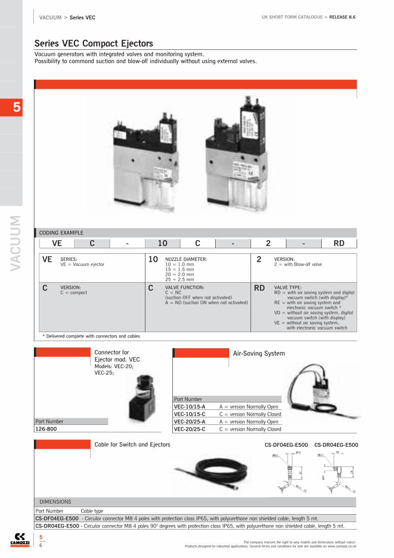
VACUUM
5
The company reserves the right to vary models and dimensions without notice.Products designed for industrial applications. General terms and conditions for sale are available on www.camozzi.co.uk
VACUUM > Series VEC UK SHORT FORM CATALOGUE > RELEASE 8.6
5
6
CODING EXAMPLE
VE
C
10
C
NOZZLE DIAMETER:10 = 1.0 mm15 = 1.5 mm20 = 2.0 mm25 = 2.5 mm
2
RD
VE C - 10 C - 2 - RD
VERSION:2 = with Blow-off valve
SERIES:VE = Vacuum ejector
VALVE FUNCTION:C = NC (suction OFF when not activated)A = NO (suction ON when not activated)
VALVE TYPE:RD = with air saving system and digital
vacuum switch (with display)*RE = with air saving system and
electronic vacuum switch *VD = without air saving system, digital
vacuum switch (with display)VE = without air saving system,
with electronic vacuum switch
VERSION:C = compact
Vacuum generators with integrated valves and monitoring system.Possibility to command suction and blow-off individually without using external valves.
Series VEC Compact Ejectors
Part Number 126-800
Connector forEjector mod. VECModels: VEC-20;VEC-25;
Air-Saving System
Part Number VEC-10/15-A A = version Normally OpenVEC-10/15-C C = version Normally ClosedVEC-20/25-A A = version Normally OpenVEC-20/25-C C = version Normally Closed
Cable for Switch and Ejectors
Part Number Cable typeCS-DF04EG-E500 - Circular connector M8 4 poles with protection class IP65, with polyurethane non shielded cable, length 5 mt.CS-DR04EG-E500 - Circular connector M8 4 poles 90O degrees with protection class IP65, with polyurethane non shielded cable, length 5 mt.
DIMENSIONS
CS-DF04EG-E500 CS-DR04EG-E500
* Delivered complete with connectors and cables
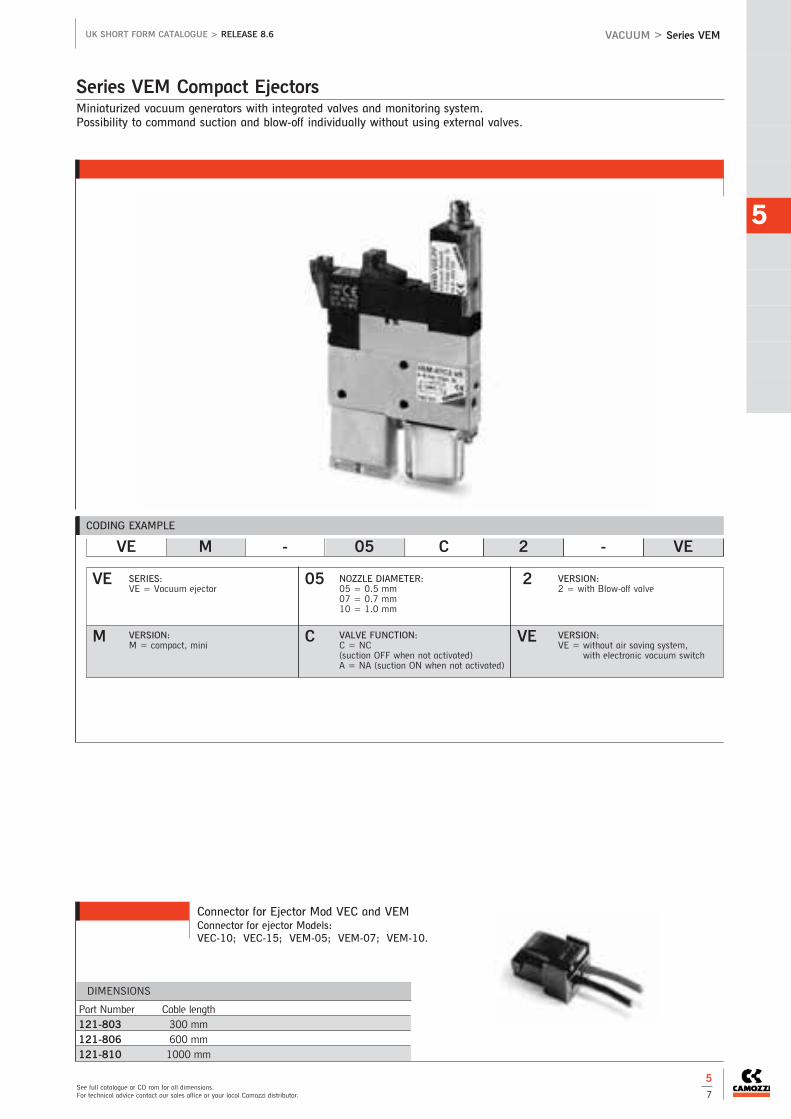
Miniaturized vacuum generators with integrated valves and monitoring system. Possibility to command suction and blow-off individually without using external valves.
Series VEM Compact Ejectors
5
See full catalogue or CD rom for all dimensions.For technical advice contact our sales office or your local Camozzi distributor.
VACUUM > Series VEMUK SHORT FORM CATALOGUE > RELEASE 8.6
5
7
Connector for Ejector Mod VEC and VEMConnector for ejector Models:VEC-10; VEC-15; VEM-05; VEM-07; VEM-10.
Part Number Cable length121-803 300 mm121-806 600 mm121-810 1000 mm
DIMENSIONS
CODING EXAMPLE
VE
M
05
C
NOZZLE DIAMETER:05 = 0.5 mm07 = 0.7 mm10 = 1.0 mm
2
VE
VE M - 05 C 2 - VE
VERSION:2 = with Blow-off valve
SERIES:VE = Vacuum ejector
VALVE FUNCTION:C = NC (suction OFF when not activated)A = NA (suction ON when not activated)
VERSION:VE = without air saving system,
with electronic vacuum switch
VERSION:M = compact, mini

VACUUM
5
The company reserves the right to vary models and dimensions without notice.Products designed for industrial applications. General terms and conditions for sale are available on www.camozzi.co.uk
VACUUM > Series NPF, Series NPM-NPR and Series VNV UK SHORT FORM CATALOGUE > RELEASE 8.6
5
8
The vulcanisation provides flexibility in all directions.Thread G1/4.
Series NPF Flexible Suction Pad Mountings
The spring plungers are used in situations where significant height differences of the workpiece have to be compensated for.Thread size M3, M5, G1/8, G1/4, plunger stroke length from 5 to 75 mm.
Series NPM - NPR Spring Plungers (non rotating)
CODING EXAMPLE
CODING EXAMPLE
These check valves are mainly used on vacuum gripper systems containing multiple suction pads in order to shut off individual suction pads which are not covered. Thread size M5, G1/8, G1/4, G3/8, G1/2.
Series VNV Check Valves
NPF - FM - 1/4 - M10X1.25
NPF
FM
1/4
THREADS G2: M10X1.25 = M10X1.251/4 = G1/4
VERSION:FM = G1 female /
G2 male
SERIES:NPF = Flexiblesuction pad mounting
THREADS G1:1/4 = G1/4
NPM - FM - 1/4 - 75
NPM
FM
1/4
75COMPENSATION STROKE:05 = 5mm10 = 10mm15 = 15mm20 = 20mm25 = 25mm50 = 50mm75 = 75mm
VERSION:FM = G1 female /
G2 maleFF = G1 female /
G2 female
SERIES:NPM = Spring plungerNPR = Spring plunger - non-rotating
THREADS: M3M51/81/4
CODING EXAMPLE
VNV - MF - M5
VNV
MF M5THREAD SIZE: M51/81/41/2
VERSION:MF = G1 male /
G2 femaleFM = G1 female /
G2 male
SERIES:VNV = Check valve

For use in vacuum systems with minor to medium levels of dirt.Direct mounting on the suction pad.
Series FVD Inline Vacuum Filters
5
See full catalogue or CD rom for all dimensions.For technical advice contact our sales office or your local Camozzi distributor.
VACUUM > Series FVD - FVTUK SHORT FORM CATALOGUE > RELEASE 8.6
5
9
Used as pre-filters and fine filters for air with varying amounts of contamination, for the protection of the vacuum generator. Mounted as protection for the ejector.
Series FVT Vacuum Cup Filters
CODING EXAMPLE
FVD 6/4 CONNECTIONS:6/4 = tube 68/6 = tube 8
50
FVD 6/4 - 50
FILTER ELEMENT:50 = 50 µm
SERIES:FVD
CODING EXAMPLE
FVT - FF - 1/4 - 80
FVT
FF
1/4
8080 = 80 µmFILTER ELEMENT:THREAD SIZE:
FF = female -female
SERIES:FVT = Cup filter
CONNECTIONS:1/8, 1/4, 3/8, 1/2, 3/4
Accessories
Mouting Foot BracketThe mod. FVT-FF-1/8-80-B is used on cup filters with ports 1/8, 1/4, 3/8 and 1/2.The mod. FVT-FF-3/4-80-B is used on cup filters with ports 3/4.

6 > Ball Valves & Non Return Valves
BALL VALVES & NON RETURN VALVES
6
Brass Two-Way Ball Valves (Economy)
6 / 2 Mini Ball Valves - Economy
6 / 3 Brass Ball Valves - Economy
Brass Two-Way Ball Valves (Premium)
6 / 4 Mini Ball Valves
6 / 5 Brass Ball Valves - Gas/WRAS Approved
Stainless Steel Two-Way Ball Valves
6 / 6 Economy Stainless Steel BallValves - Two-Piece Design

6
Brass Three-Way Ball Valves
6 / 12 Brass Ball Valves Three-Way
Non-Return Valves
6 / 13 Non-Return Valves
Eurofly Valves
6 / 7 Eurofly Valves
Direct Mount Ball Valves (for actuation)
6 / 8 Brass Ball Valves - with ISO Pad
6 / 9 Stainless Steel Ball Valves - with ISO Pad
Exhausting Brass Ball Valves
6 / 10 Brass Ball Valves - Exhausting
6 / 11 Lockable Safety Ball Valve

BALL VALVES & NON RETURN VALVES
6
The company reserves the right to vary models and dimensions without notice.Products designed for industrial applications. General terms and conditions for sale are available on www.camozzi.co.uk
BALL VALVES & NON RETURN VALVES > Mini Ball Valves UK SHORT FORM CATALOGUE > RELEASE 8.6
6
2
Connections: 1/4, 3/8, 1/2
Our range of Mini Ball Valves offers a wide variety of choices for the design engineer.
Mini Ball Valves - Economy
Dimensions (mm)
Part Number L L1 h h1 R Kv
AV5004 1/4 40 - 29 13.8 20.5 4.3
AV5004 3/8 40 - 29 13.8 20.5 2.7
AV5004 1/2 43 - 31 15.8 20.5 5.4
Technical DataMediaMost non-corrosive liquids includingair, water and fuels
Operating Pressure10 bar (147 p.s.i.)
Operating Temperature-10oC to +90oC
MaterialsBrass - Bright Nickel Finish
Actuation Details90O rotation of leverWe recommend that the valve is usedin either the fully open or fully closedposition. In addition, the valve shouldbe actuated at least twice a year
Dimensions (mm)
Part Number I I1 L h R Ch
AV5003 1/4 10 - 40 22 18 20
AV5003 3/8 10 - 40 22 18 20
AV5003 1/2 10 - 43 30 22 20
Part Number: AV5003
Lever - Female/Female
Part Number: AV5004
Lever - Male/Female

Connections: 1/4, 3/8, 1/2, 3/4, 1, 1 1/4, 1 1/2, 2
Our economy range of Brass Ball Valves offering a cost saving solution suitable for many applications.
Brass Ball Valves - Economy
6
See full catalogue or CD rom for all dimensions.For technical advice contact our sales office or your local Camozzi distributor.
BALL VALVES & NON RETURN VALVES > Brass Ball ValvesUK SHORT FORM CATALOGUE > RELEASE 8.6
Dimensions (mm)
Part Number L D H B E
AV6000 3/8 45.5 86 36 10 13.5
AV6000 1/2 57.7 88 40 15 14.5
AV6000 3/4 67 88 44 20 15.5
AV6000 1 88.8 111 58 25 20
AV6000 1 1/4 94.5 130 66.5 32 21.5
AV6000 1 1/2 102.9 130 70.5 40 22
AV6000 2 126.3 158 83 50 20
Part Number: AV6000
Steel Handle with plastic sleeve - Female/Female
Technical DataMediaMost non-corrosive liquids and gasesincluding air, water, solvents andfuels.
Operating Pressure16 Bar (230 p.s.i.)
Operating Temperature-10oC to +90oC
MaterialsBody: Nickel plated brassBonnet: BrassSeat: PTFEBall: Chrome plated brassStem: BrassNut: BrassPress nut: BrassGasket: PTFELever Handle: Steel with plasticsleeveSeals: PTFE
Actuation90o rotation of the lever.We recommend that the valve is usedin either the fully open or fully closedposition. In addition, the valve shouldbe actuated at least twice a year
9
8
7
6
5
4
3
2
1
6
3
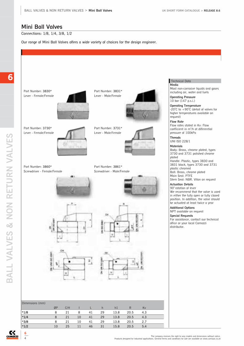
BALL VALVES & NON RETURN VALVES
6
The company reserves the right to vary models and dimensions without notice.Products designed for industrial applications. General terms and conditions for sale are available on www.camozzi.co.uk
BALL VALVES & NON RETURN VALVES > Mini Ball Valves UK SHORT FORM CATALOGUE > RELEASE 8.6
6
4
Connections: 1/8, 1/4, 3/8, 1/2
Our range of Mini Ball Valves offers a wide variety of choices for the design engineer.
Mini Ball Valves
Dimensions (mm)
ØP C/H I L h h1 R Kv
*1/8 8 21 8 41 29 13.8 20.5 4.3
*1/4 8 21 10 41 29 13.8 20.5 4.3
*3/8 8 21 10 41 29 13.8 20.5 2.7
*1/2 10 25 11 46 31 15.8 20.5 5.4
Technical DataMediaMost non-corrosive liquids and gasesincluding air, water and fuels
Operating Pressure10 bar (147 p.s.i.)
Operating Temperature-20oC to +90oC (detail of valves forhigher temperatures available onrequest)
Flow RateFlow rates stated in Kv: Flowcoefficient in m3/h at differentialpressure of 100kPa
ThreadsUNI ISO 228/1
MaterialsBody: Brass, chrome plated, types3730 and 3731 polished chromeplatedHandle: Plastic, types 3830 and3831 black, types 3730 and 3731plastic chromedBall: Brass, chrome platedMain Seal: PTFEStem Seal: NBR. Viton on request
Actuation Details90O rotation of leverWe recommend that the valve is usedin either the fully open or fully closedposition. In addition, the valve shouldbe actuated at least twice a year
Additional OptionsNPT available on requestSpecial RequestsFor assistance, contact our technicaloffice or your local Camozzidistributor.
Part Number: 3830*
Lever - Female/Female
Part Number: 3831*
Lever - Male/Female
Part Number: 3730*
Lever - Female/Female
Part Number: 3731*
Lever - Male/Female
Part Number: 3860*
Screwdriver - Female/Female
Part Number: 3861*
Screwdriver - Male/Female

Connections: 1/4, 3/8, 1/2, 3/4, 1, 1 1/4, 1 1/2, 2, 2 1/2, 3, 4
Our range of Brass Ball Valves offering a cost saving solution suitable for many applications.
Brass Ball Valves - Gas/WRAS Approved
6
See full catalogue or CD rom for all dimensions.For technical advice contact our sales office or your local Camozzi distributor.
BALL VALVES & NON RETURN VALVES > Brass Ball ValvesUK SHORT FORM CATALOGUE > RELEASE 8.6
Dimensions (mm) and Pressures
DN L H CH R h Kv PN Kg
*1/4 8 51.5 23 20 95 48 5.4 64 0.14
*3/8 10 51.5 23 20 95 48 6 64 0.13
*1/2 15 59 30 25 95 52 16.3 30 0.17
*3/4 20 67 36 31 110 60 29.5 30 0.29
*1 25 81.5 43.5 38 110 70 43 30 0.44
*1 1/4 32 94 53 48 160 77.5 89 25 0.76
*1 1/2 40 102.4 65 54 160 82.5 230 25 1.02
*2 50 123 80 67 170 102 265 25 1.75
*2 1/2 65 152 111 90 205 123 540 25 3.71
*3 80 177 136 105 205 133 873 25 5.90
*4 100 114 166 130 260 165 1390 25 10.00
Part Number: 1600*
Aluminium Handle - Female/Female
Part Number: 1620* (1/4 - 1 only)
Aluminium Butterfly Handle - Female/Female
Part Number: 1610*
Steel with Black Plastic Coated Handle - Female/Female
Part Number: 6273*
Steel with Yellow Plastic Coated Handle - Female/Female
Gas approved to BSEN331 1998
Technical DataMediaMost non-corrosive liquids and gasesincluding air, water, solvents andfuels.6273 range gas approved toBSEN331 1998
Operating PressureNominal working pressure (PN) inbar. (see chart)
Operating Temperature-20oC to +130oC
Flow RatesFlow rates stated in Kv: Flowcoefficient in m3/h at differentialpressure of 100kPa
ThreadsFemale-Female UNI ISO 7/1
MaterialsBody: Nickel plated brassBall: Chromed brassSeals: PTFEStem Seals: NBRLever Handle: Steel black enamelled ‘T’ Handle: Aluminium blackenamelled
Actuation90o rotation of the lever.We recommend that the valve is usedin either the fully open or fully closedposition. In addition, the valve shouldbe actuated at least twice a year
Additional OptionsSuitable for vacuum applications:maximum 103 torr. The Series 1600valve range is only illustrated in thiscatalogue up to 2”. It is also availablein sizes 2 1/2”, 3” and 4”.Lockable handle available on request
Special RequestsFor assistance, contact our technicaloffice or your local Camozzidistributor.
6
5

BALL VALVES & NON RETURN VALVES
6
The company reserves the right to vary models and dimensions without notice.Products designed for industrial applications. General terms and conditions for sale are available on www.camozzi.co.uk
BALL VALVES & NON RETURN VALVES > Stainless Steel Ball Valves UK SHORT FORM CATALOGUE > RELEASE 8.6
6
6
Connections: 1/4, 3/8, 1/2, 3/4, 1, 1 1/4, 1 1/2, 2
2-piece Stainless Steel Quarter Turn Ball Valve with all wetted parts Stainless Steel AISI316. Other metal parts in StainlessSteel AISI304. Available with NPT Threads.
Economy Stainless Steel Ball Valves - Two-Piece Design
Technical DataMediaAny application with media suitableto material of construction
Operating PressureNominal working pressure (PN) inBAR - See chartVacuum: Maximum 10-3 torr.
Operating Temperature-20oC to +160oC
Flow RatesFlow rates stated in Kv: Flowcoefficient in m3/h at differentialpressure of 100kPa
ThreadsISO 228/1
MaterialsBody: CF8M Stainless SteelBall: CF8M Stainless SteelSeals: PTFEHandle: Stainless Steel AISI430 withplastic grip
Actuation90O rotation of leverWe recommend that the valve is usedin either the fully open or fully closedposition. In addition, the valve shouldbe actuated at least twice a year
Additional Options700023 - Female/Female NPT
Special RequestsFor assistance, contact our technicaloffice.
Dimensions (mm) and Pressures
Size DN U Bore A H I L R P Kv PN
*02 1/4 8 10 28 30 10 53.5 110.5 44.5 5.4 64
*03 3/8 10 10 28 30 10 53.5 110.5 44.5 6 64
*04 1/2 15 14.2 30.5 32.5 13 60 110.5 47 16.3 64
*05 3/4 20 19 37 40 14 70 131.5 54.5 29.5 40
*06 1 25 24.2 41 49 17 79 131.5 58.5 43 40
*07 1 1/4 32 30 50 62 19 91 174.5 70 89 25
*08 1 1/2 40 38 57 75 19.5 103 174.5 76.5 230 25
*10 2 50 50 66 95 22.5 124 174.5 86 265 25
Part Number: 704000*

Connections: 1/2, 3/4, 1, 1 1/4, 1 1/2, 2, 2 1/2, 3, 4
New patented design Brass Butterfly Valve with Throttling Lever offers the user the ability of total control of line media withthe benefit of no back cavity, anti-water hammer, reduced lime scale build up and competitive prices.
Eurofly Valves
6
See full catalogue or CD rom for all dimensions.For technical advice contact our sales office or your local Camozzi distributor.
BALL VALVES & NON RETURN VALVES > Eurofly ValvesUK SHORT FORM CATALOGUE > RELEASE 8.6
Technical DataMediaMost non-corrosive liquids and gasesincluding air, water, solvents, fuelsand propane.
Operating Pressure16 bar max
Operating Temperature-10oC to +130oC
Flow RatesFlow rates stated in Kv: Flowcoefficient in m3/h at differentialpressure of 100kPa
ThreadsUNI ISO 7/1
MaterialBody: Brass CW 617N UNI EN12165 Nickel-platedSleeve: Brass CW 617N UNI EN12165 Nickel-platedDisc: Pei-polyethereimide.Seal: NBR 80shStem Seal: P.T.F.E - TeflonGland: Brass CW 617N UNI EN12164Nut: Steel 6 sSeal: P.T.F.E - TeflonThrottling Plate: Steel Fe P11 -UNI 5887Spring: Stainless steel - AISI 302Pin: SteelHandle: Coated steel - P11 UNI5867Stem: Brass CW 617N UNI EN12164Lever-Handle: art. 600000 Coatedsteel Fe P11 UNI 5867art. 600001 Aluminium
Actuation90O rotation of leverWe recommend that the valve is usedin either the fully open or fully closedposition. In addition, the valve shouldbe actuated at least twice a year
Additional OptionsEPDM and Viton Seals for highertemperature applications
Special RequestsFor assistance, contact our technicaloffice or your local Camozzidistributor.
1
10
14
13
12
11
9
8
7
6
5
4
3
2
Dimensions (mm)
Thread DN P I L H CH R h Kv Kg
*04 1/2 15 16 15 48.5 31 25 95 46.5 8.5 0.19
*05 3/4 20 21 16.3 56 38 31 95 50.5 17 0.25
*06 1 25 27 19.1 64 46 38 95 54 27 0.36
*07 1 1/4 32 34 21.4 76 55.5 48 120 71.5 50 0.67
*08 1 1/2 40 41 21.4 82 65.5 54 120 76.5 82.5 0.88
*10 2 50 52 25.7 93 77.5 67 150 86.5 136.5 1.33
*12 2 1/2 65 65 30.2 112 102 90 205 115 240 3.35
*14 3 80 80 33.3 129.5 122 105 205 125 340 4.90
*18 4 100 103 39.3 146 145 130 205 140 550 6.50
Part Number: 600000*
Steel Flow Control Lever - Female/Female
6
7

BALL VALVES & NON RETURN VALVES
6
The company reserves the right to vary models and dimensions without notice.Products designed for industrial applications. General terms and conditions for sale are available on www.camozzi.co.uk
BALL VALVES & NON RETURN VALVES > Brass Ball Valves UK SHORT FORM CATALOGUE > RELEASE 8.6
6
8
Connections: 1/4, 3/8, 1/2, 3/4, 1, 1 1/4, 1 1/2, 2, 2 1/2, 3, 4
Full bore brass ball valves with ISO 5211 mounting pad for direct mounting of pneumatic/electric actuators for on-offapplications of most non-corrosive media. Body seals energised with Viton ‘O’ rings.
Only for actuation - no lever available
Brass Ball Valves - with ISO Pad
Technical DataMediaMost non-corrosive liquids and gasesincluding air, water, solvents, fuelsand propane
Operating PressureSee chart
Operating Temperature-20oC to +160oC
Flow RatesFlow rates stated in Kv: Flowcoefficient in m3/h at differentialpressure of 100kPa
ThreadsUNI ISO 7/1
MaterialsBody: Brass, nickel platedBall: Brass, chrome platedSeals: PTFE with Viton ‘O’ RingSize: 1/4” to 4” UNI ISO 7/1
Actuation DetailsRefer to chart for torque and paddetails
Additional OptionsNPTF - Series 250N
Available with springreturn (dead mans)lever.
Available withPneumatic Actuators
Available with ElectricActuators
Special RequestsFor assistance, contact our technicaloffice or your local Camozzidistributor.
Dimensions (mm) and Pressures
DN 2 A B C d1 E H L Kv PN Torque
*1/4 8 38 32.5 9 36 6 9 33.5 67 5.4 40 6 NM
*3/8 10 38 32.5 9 36 6 9 33.5 67 6 40 6 NM
*1/2 15 38 32.5 9 36 6 9 33.5 67 16.3 40 6 NM
*3/4 20 38 34.5 9 36 6 9 40 76 29.5 40 6 NM
*1 25 38 45.5 9 36 6 9 49 90 43 40 6 NM
*1 1/4 32 38 59 9 36 6 9 58.5 102 89 40 6 NM
*1 1/2 40 50 64 11 50 7 11 73 114 230 40 17 NM
*2 50 50 73.25 11 50 7 11 91.5 138 265 40 17 NM
*2 1/2 65 70 88.5 14 70 9 15 114.5 165 540 25 31 NM
*3 80 70 98 14 70 9 15 136 188 873 16 31 NM
*4 100 70 116.5 17 70 9 17.5 166 225 1390 16 73 NM
Part Number: 2500*

Dimensions (mm) and Pressures
Threads DN U Bore L H A B E C 1 Z Kv PN Torque
*04 1/2 15 14.2 67 34.5 41.5 9 9 36 6 38 16.3 64 6 NM
*05 3/4 20 19 78 42 43.5 9 9 36 6 38 29.5 64 6 NM
*06 1 25 24.5 90 51.5 53.5 9 9 36 6 38 43 64 6 NM
*07 1 1/4 32 30 100 64.5 57 9 9 36 6 38 89 64 6 NM
*08 1 1/2 40 38 112 77 74 11 11 50 7 50 230 64 17 NM
*10 2 50 50 135 97 83.25 11 11 50 7 50 265 64 17 NM
Connections: 1/2, 3/4, 1, 1 1/4 1 1/2, 2
Full bore brass ball valves with ISO 5211 mounting pad for direct mounting of pneumatic/electric actuators for on-offapplications of most non-corrosive media. Body seals energised with Viton ‘O’ rings.
Only for actuation - no lever available
Stainless Steel Ball Valves - with ISO Pad
6
See full catalogue or CD rom for all dimensions.For technical advice contact our sales office or your local Camozzi distributor.
BALL VALVES & NON RETURN VALVES > Stainless Steel Ball ValvesUK SHORT FORM CATALOGUE > RELEASE 8.6
6
9
Technical DataMediaAny application with media suitableto stainless steel (materials ofconstruction)
Operating Pressure10-3 torr max vacuum to 64 bar
Operating Temperature-20oC to +160oC
Flow RatesFlow rates stated in Kv: Flowcoefficient in m3/h at differentialpressure of 100kPa
ThreadsISO 7/1 RP
MaterialsBody: CF8MBall: AISI 316Seals: PTFE with Viton ‘O’ RingStem: AISI 316Size: 1/4 to 2 UNI ISO 7/1
Actuation DetailsRefer to chart for torque and paddetails
Additional OptionsNPTF - Series 700076
Available with springreturn (dead mans)lever.
Available withPneumatic Actuators
Available with ElectricActuators
Special RequestsFor assistance, contact our technicaloffice or your local Camozzidistributor.
Part Number: 703000*

BALL VALVES & NON RETURN VALVES
6
The company reserves the right to vary models and dimensions without notice.Products designed for industrial applications. General terms and conditions for sale are available on www.camozzi.co.uk
BALL VALVES & NON RETURN VALVES > Brass Ball Valves UK SHORT FORM CATALOGUE > RELEASE 8.6
6
10
Connections: 1/4, 3/8, 1/2, 3/4, 1
For use as an on-off valve for pneumatic systems.In the off position, downstream air is exhausted to atmosphere through a small vent hole in the valve body.In this way the danger of pressurised air remaining in the system after shut-off can be eliminated.
Brass Ball Valves - Exhausting
Technical DataMediaCompressed Air
Operating Pressure10 bar
Operating Temperature-10oC to +100oC
Flow RatesFlow rates stated in Kv: Flowcoefficient in m3/h at differentialpressure of 100kPa
ThreadsUNI ISO 7/1
MaterialsBody: Brass, nickel platedBall: Brass, hard chromeSeals: PTFEHandle: Steel zinc plated, red plasticcoatedDirection flow: As indicated by arrowConnections: 1/4 to 1 UNI ISO 7/1Flow coefficient m3/h - see Kv columnof dimensions
Actuation DetailsAs per 1700 valve
Additional OptionsLockable handle
Special RequestsFor assistance, contact our technicaloffice or your local Camozzidistributor.
Dimensions (mm) and Pressures
Thread DN ØP A B h ØH I L R Ch Kv PN Kg
*1/4 8 10 59.5 17.5 42 28 11 52 96 22 5.4 10 0.20
*3/8 10 10 59.5 17.5 42 28 11.4 52 96 22 6 10 0.19
*1/2 15 15 66 20 46 33 15 62 96 25 16.3 10 0.22
*3/4 20 20 82.5 24.5 58 39 16.3 69 121 31 29.5 10 0.36
*1 25 25 98 36 62 49 19.1 83 121 41 43 10 0.55
Part Number: 5110*

Connections: 1/4, 3/8, 1/2, 1
Our lockable safety ball valve is for use as an on-off valve for pneumatic systems. In off position, vent hole in valve bodyallows air to be exhausted. In the off position, downstream air is exhausted to atmosphere through a small vent hole in thevalve body. Locking feature allows maintenance and setting activities to be carried out safely on the system and prevents airsupply being reactivated inadvertently.
Lockable Safety Ball Valve
6
See full catalogue or CD rom for all dimensions.For technical advice contact our sales office or your local Camozzi distributor.
BALL VALVES & NON RETURN VALVES > Lockable Safety Ball ValveUK SHORT FORM CATALOGUE > RELEASE 8.6
Technical DataMediaFor use as an on-off valve forpneumatic systems
Operating Pressure0 to 16 bar
Operating Temperature-20oC to +90oC
ThreadsUNI ISO 7/1
MaterialsBody: Brass, nickel platedBall: Brass, hard chromeSeals: PTFEHandle: Steel zinc plated, blue plasticcoatedDirection flow: As indicated by arrow
Special RequestsFor assistance, contact our technicaloffice or your local Camozzidistributor.
D(inch) DN(mm) J(mm) L(mm) G(mm) A(mm) H(mm) AF(mm)
*B00 1/4 8 12 45 22.5 96 47.5 20
*C00 3/8 9.5 12 45 22.5 96 47.5 20
*D00 1/2 15 15.5 59 29.5 96 52 25
*F00 1 24 21 81 40.5 117 63.5 40
6
11
Part Number: S93*

BALL VALVES & NON RETURN VALVES
6
The company reserves the right to vary models and dimensions without notice.Products designed for industrial applications. General terms and conditions for sale are available on www.camozzi.co.uk
BALL VALVES & NON RETURN VALVES > Brass Ball Valves Three-Way UK SHORT FORM CATALOGUE > RELEASE 8.6
6
12
Connections: 1/4, 3/8, 1/2, 3/4, 1, 1 1/4, 1 1/2, 2
Full bore, 3-way L-port or T-port ball valves for control of air, water, oil and some solvents and fuels.On site selection of desired flowpath by simple lever positioning system (see chart below).ISO Pad for direct mounting of actuator.
Brass Ball Valves Three-Way
Technical DataMediaMost non-corrosive liquids and gasesincluding air, water, solvents, fuelsand propane.Operating Pressure10-3 torr vacuum to see chart
Operating Temperature-20OC to + 160OC
Flow RatesFlow rates stated in Kv: Flowcoefficient in m3/h at differentialpressure of 100kPa
ThreadsUNI ISO 7/1
MaterialsBody: Brass, Nickel-platedBalls: Brass, hard chromedSeal: PTFE and VITONLever: Steel, plastic coated black
Actuation Details90O rotation of lever. We recommendthat the valve is used in either thefully open or fully closed position. Inaddition, the valve should be actuatedat least twice a year
Additional OptionsNPTF - NPT
Special RequestsFor assistance, contact our technicaloffice or your local Camozzidistributor.
Dimensions (mm) and Pressures
Size DN H L m R h Øb Øc e f g n Kv PN Torque
*1/4 8 34 67 33.5 120 62.5 6 36 (ISO F03) 5 30.5 9 38 9 2.8 30 6 NM
*3/8 10 34 67 33.5 120 62.5 6 36 (ISO F03) 5 30.5 9 38 9 3 30 6 NM
*1/2 15 39 77 38.5 120 63.5 6 36 (ISO F03) 5 32.7 9 38 9 3.9 30 6 NM
*3/4 20 48 87 43.5 170 75 7 50 (ISO F05) 7 41.5 11 50 11 7.9 30 17 NM
*1 25 60 105 52.5 170 79.5 7 50 (ISO F05) 7 47 11 50 11 13 16 17 NM
*1 1/4 32 72 122.5 61.25 170 93 7 50 (ISO F05) 7 59.5 11 50 11 20.7 10 17 NM
*1 1/2 40 86 138.5 69.25 230 113.5 9 70 (ISO F07) 8 73.85 15 70 14 38.7 10 30.5 NM
*2 50 111 166 83 230 123.5 9 70 (ISO F07) 8 85 15 70 14 54 10 30.5 NM
Flowpaths (indicated by markings on the stem)
Part Number: 3500* (T-port), 3600 (L-Port)

Connections: 3/8, 1/2, 3/4, 1, 1 1/4, 1 1/2, 2, 2 1/2, 3, 4Brass & Stainless Steel
Suitable for a wide range of fluids.
Non-Return Valves
6
See full catalogue or CD rom for all dimensions.For technical advice contact our sales office or your local Camozzi distributor.
BALL VALVES & NON RETURN VALVES > Non-Return ValvesUK SHORT FORM CATALOGUE > RELEASE 8.6
Part Number: 100000* - Brass Valves
Part Number: CRO* - Stainless Steel
Technical DataMediaSuitable for air lines and generally forfluids compatible with materials usede.g. air, gas, oil, water etc. (NOT RECOMMENDED FOR USEDIRECTLY ON OR ADJACENT TOCOMPRESSORS)
Opening Pressure20 - 25 millibar
Operating Pressure3/8 to 3/4 - 40 bar1 to 1 1/4 - 25 bar1 1/2 to 2 - 16 bar2 1/2 to 3 - 12 bar4 - 10 bar
Operating Temperature-20oC to +100oC
MaterialsBody: BrassSeals: NBR
InstallationIn rigid pipework
PositionAs indicators
Special RequestsFor assistance, contact our technicaloffice or your local Camozzidistributor.
Technical DataMediaSuitable for a wide range of fluidsincluding hard hot water,hydrocarbons, corrosive and abrasiveliquids
Opening Pressure0.03 BAR
Operating PressureNominal working pressure (PN) in bar- see chartNot suitable for Vacuum
Operating Temperature-20oC to +150oC (on request PTFE Seal -20oC to+200oC )
MaterialsMetal parts: Stainless steel AISI 304, (316 stainless steel on request)Seal: Viton
Special RequestsFor assistance, contact our technicaloffice or your local Camozzidistributor.
Dimensions (mm) and Pressures
A B C PN Weight (gm)
*1/2 38 64 16 95
*3/4 45 72 16 142
*1 53 88 16 197
*1 1/4 62 99 16 320
*1 1/2 78 117 16 400
*2 85 115 16 676
*2 1/2 106 127 16 1075
*3 128 140 16 1630
*4 163 167 16 2770
Dimensions (mm) and Pressures
DN A B C CH Kv PN kg
*03 3/8 10 47 21.5 26.5 22 3.9 40 0.09
*04 1/2 15 59 25 34.5 25 5.2 40 0.14
*05 3/4 20 65 30.5 42 31 9.4 40 0.21
*06 1 25 75 37.5 49 38 14.5 25 0.32
*07 1 1/4 32 83 47.5 61 48 23.5 25 0.53
*08 1 1/2 40 89 53.5 73 54 33.5 16 0.75
*10 2 50 101.5 68 88 67 52 16 1.13
*12 2 1/2 65 121 82 111.5 83 84.3 12 2.00
*14 3 80 136 97.5 133 98 135.4 12 3.12
*18 4 100 158 127 163 128 193.2 10 5.64
6
13
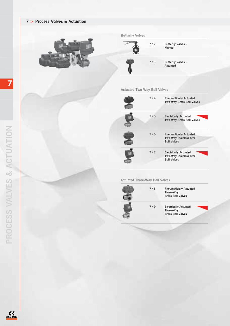
7 > Process Valves & Actuation
PROCESS VALVES & ACTUATION
7
Butterfly Valves
7 / 2 Butterfly Valves - Manual
7 / 3 Butterfly Valves - Actuated
Actuated Two-Way Ball Valves
7 / 4 Pneumatically Actuated Two-Way Brass Ball Valves
7 / 5 Electrically Actuated Two-Way Brass Ball Valves
7 / 6 Pneumatically Actuated Two-Way Stainless Steel Ball Valves
7 / 7 Electrically Actuated Two-Way Stainless Steel Ball Valves
Actuated Three-Way Ball Valves
7 / 8 Pneumatically ActuatedThree-WayBrass Ball Valves
7 / 9 Electrically ActuatedThree-WayBrass Ball Valves

7
7 / 24 Series NA NAMUR Valves
AccessoriesKnife Gate Valves
Industrial Solenoid Valves
7 / 10 Manual Hand Wheel
7 / 11 Air Actuated
7 / 12 Pneumatically Operated Globe Valves
7 / 13 Pneumatically Operated Bronze Angle Seat Valve for High Temperature
7 / 14 Pneumatically Operated Gate Valves
Other Actuated Valves
7 / 15-17 Solenoid Valves - Direct Acting
7 / 18-19 Solenoid Valves - Servo Assisted
7 / 20 Solenoid Valves - Coupled Diaphragm
7 / 21 Automatic DrainValve
7 / 22 Solenoid Valves - Direct Acting Normally ClosedStainless Steel
7 / 23 Solenoid Valves - Coupled Diaphragm NormallyClosed Stainless Steel
New

Wafer Types 600104 & 600105
Wafer Butterfly Valve with Handle and Body made of Cast Iron - PN16 and ANSI 150. The Butterfly Valve series EuroflyWafer and Lug have been manufactured to meet the industrial applications of water treatment, fire-fighting and plumbingplants. They can be used for all the applications where fluid regulation is required. The Seat construction is made with arigid plastic ring covered with thick EPDM or Buna or Viton coating, depending on the media. This system offers a soft andreliable closure, a long cycling life and low torque. Due to the seat geometry it isparticularly easy to replace.
Butterfly Valves - Manual
PROCESS VALVES & ACTUATION
The company reserves the right to vary models and dimensions without notice.Products designed for industrial applications. General terms and conditions for sale are available on www.camozzi.co.uk
PROCESS VALVES & ACTUATION > Butterfly Valves UK SHORT FORM CATALOGUE > RELEASE 8.6
7
ISO Mounting Dimensions
Technical DataMediaAny application with media suitableto materials of construction
Operating Pressure16 BAR
Operating Temperature-20OC to +120OC EPDM
Flange RatingPN16 / ANSI 150
MaterialsBody: Cast IronDisc: 600105: Stainless Steel
600104: Cast IronStem: AISI 420Liner: EPDMLever: EN GJL 250
Additional OptionsActuated: Pneumatic electric gearboxNBR SeatViton Seat
Special RequestsFor assistance, contact our technicaloffice or your local Camozzidistributor.
Also available in Lugged Pattern
Also available: Gearbox Operated
7
2
Part Number: 600104* Cast Iron Disc / EPDM seat
600105* Stainless Steel Disc / EPDM seat
Also available withlimit switch box
Dimensions (mm)
Size DN NPS A B C D E L F Kg
*07 32 1 1/4 80.00 189.00 57.00 110.00 165.00 30.00 33.00 2.10
*08 40 1 1/2 100.00 200.00 68.00 110.00 165.00 30.00 33.00 2.30
*10 50 2 100.00 236.10 71.40 142.70 267.00 30.00 43.00 3.50
*12 65 2 1/2 120.00 255.20 77.80 155.40 267.00 30.00 46.00 4.25
*14 80 3 127.00 272.80 89.00 161.80 267.00 30.00 46.00 4.20
*18 100 4 161.00 302.00 102.00 178.00 267.00 30.00 52.00 5.60
*19 125 5 190.00 335.50 123.00 190.50 267.00 30.00 56.00 7.10
*20 150 6 215.00 365.20 138.00 205.20 267.00 30.00 56.00 7.20
*21 200 8 268.00 439.50 168.00 237.00 358.00 35.00 60.00 13.90
*77 250 10 325.00 509.80 207.00 268.30 358.00 35.00 68.00 22.00
*78 300 12 400.00 586.50 243.50 308.50 358.00 35.00 78.00 36.50
DN32-40 valves only available with Stainless Steel Disc.
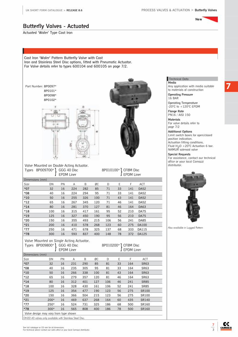
Valve Mounted on Single Acting Actuator.Types 8P009800* GGG 40 Disc 8P010200* CF8M Disc
EPDM Liner EPDM Liner
Actuated ‘Wafer’ Type Cast Iron
Cast Iron ‘Wafer’ Pattern Butterfly Valve with Cast Iron and Stainless Steel Disc options, fitted with Pneumatic Actuator. For Valve details refer to types 600104 and 600105 on page 7/2.
Butterfly Valves - Actuated
See full catalogue or CD rom for all dimensions.For technical advice contact our sales office or your local Camozzi distributor.
PROCESS VALVES & ACTUATION > Butterfly ValvesUK SHORT FORM CATALOGUE > RELEASE 8.6
7Technical DataMediaAny application with media suitableto materials of construction
Operating Pressure16 BAR
Operating Temperature-20OC to +120OC EPDM
Flange RatePN16 / AISI 150
MaterialsFor valve details refer to page 7/2
Additional OptionsLimit switch boxes for open/closedposition indication.Actuation fitting conditions. Fluid H2O +20OC Actuation 6 bar.NAMUR solenoid valve
Special RequestsFor assistance, contact our technicaloffice or your local Camozzidistributor.
Also available in Lugged Pattern
Dimensions (mm)
Size DN PN A B ØC D E F ACT
*07 32 16 224 282 85 71 33 141 DA52
*08 40 16 224 294 95 71 33 141 DA52
*10 50 16 255 326 100 71 43 141 DA52
*12 65 16 267 345 120 71 46 141 DA52
*14 80 16 281 370 127 81 46 164 DA63
*18 100 16 315 417 161 95 52 210 DA75
*19 125 16 327 450 190 95 56 210 DA75
*20 150 16 355 493 215 106 56 241 DA85
*21 200 16 410 578 268 123 60 275 DA100
*77 250 16 471 678 325 137 68 333 DA115
*78 300 16 593 837 400 148 78 372 DA125
Dimensions (mm)
Size DN PN A B ØC D E F ACT
*07 32 16 231 290 85 81 33 164 SR63
*08 40 16 235 305 95 81 33 164 SR63
*10 50 16 266 338 100 81 43 164 SR63
*12 65 16 279 357 120 81 46 164 SR63
*14 80 16 312 401 127 106 46 241 SR85
*18 100 16 328 430 161 106 52 241 SR85
*19 125 16 354 477 190 123 56 275 SR100
*20 150 16 366 504 215 123 56 275 SR100
*21 200* 16 469 637 268 164 60 435 SR140
*77 250* 16 524 731 325 186 68 500 SR160
*78 300* 16 565 808 400 186 78 500 SR160
Valve design may vary from type shown
DN32-40 valves only available with Stainless Steel Disc.
Valve Mounted on Double Acting Actuator.Types 8P009700* GGG 40 Disc 8P010100* CF8M Disc
EPDM Liner EPDM Liner} }
7
3
} }
Part Number: 8P0097*
8P0101*
8P0098*
8P0102*
New
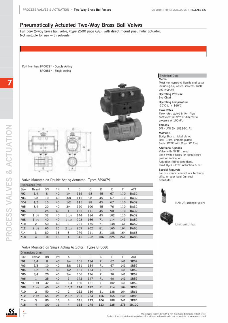
Full bore 2-way brass ball valve, (type 2500 page 6/8), with direct mount pneumatic actuator.Not suitable for use with solvents.
Pneumatically Actuated Two-Way Brass Ball Valves
PROCESS VALVES & ACTUATION
The company reserves the right to vary models and dimensions without notice.Products designed for industrial applications. General terms and conditions for sale are available on www.camozzi.co.uk
PROCESS VALVES & ACTUATION > Two-Way Brass Ball Valves UK SHORT FORM CATALOGUE > RELEASE 8.6
7
Valve Mounted on Double Acting Actuator. Types 8P0079
Valve Mounted on Single Acting Actuator. Types 8P0081
Technical DataMediaMost non-corrosive liquids and gasesincluding air, water, solvents, fuelsand propane
Operating PressureSee Chart
Operating Temperature-20OC to + 160OC
Flow RatesFlow rates stated in Kv: Flowcoefficient in m3/h at differentialpressure of 100kPa
ThreadsDN - UNI EN 10226-1 Rp
MaterialsBody: Brass, nickel platedBall: Brass, chrome platedSeals: PTFE with Viton ‘O’ Ring
Additional OptionsValve with NPTF thread.Limit switch boxes for open/closedposition indication.Actuation fitting conditions. Fluid H2O +20OC Actuation 6 bar.
Special RequestsFor assistance, contact our technicaloffice or your local Camozzidistributor.
NAMUR solenoid valves
Limit switch box
Dimensions (mm)
Size Thread DN PN A B C D E F ACT
*02 1/4 8 40 1/4 115 98 45 67 110 DA32
*03 3/8 10 40 3/8 115 98 45 67 110 DA32
*04 1/2 15 40 1/2 115 98 45 67 110 DA32
*05 3/4 20 40 3/4 120 100 45 76 110 DA32
*06 1 25 40 1 135 111 45 90 110 DA32
*07 1 1/4 32 40 1 1/4 144 114 45 102 110 DA32
*08 1 1/2 40 40 1 1/2 203 166 71 114 141 DA52
*10 2 50 40 2 221 175 71 138 141 DA52
*12 2 1/2 65 25 2 1/2 259 202 81 165 164 DA63
*14 3 80 16 3 279 211 81 188 164 DA63
*18 4 100 16 4 345 262 106 225 241 DA85
Dimensions (mm)
Size Thread DN PN A B C D E F ACT
*02 1/4 8 40 1/4 151 134 71 67 141 SR52
*03 3/8 10 40 3/8 151 134 71 67 141 SR52
*04 1/2 15 40 1/2 151 134 71 67 141 SR52
*05 3/4 20 40 3/4 156 136 71 76 141 SR52
*06 1 25 40 1 172 147 71 90 141 SR52
*07 1 1/4 32 40 1 1/4 180 151 71 102 141 SR52
*08 1 1/2 40 40 1 1/2 214 177 81 114 164 SR63
*10 2 50 40 2 232 186 81 138 164 SR63
*12 2 1/2 65 25 2 1/2 291 234 106 165 241 SR85
*14 3 80 16 3 311 243 106 188 241 SR85
*18 4 100 16 4 358 275 123 225 275 SR100
Part Number: 8P0079* - Double Acting
8P0081* - Single Acting
7
4

24V AC/DC 100-240V AC
**002 **004
Voltage Supply Order Code
For Mod. VB015 12V AC/DC
**001
For Mod. VB030-350 12V DC
**001
See full catalogue or CD rom for all dimensions.For technical advice contact our sales office or your local Camozzi distributor.
PROCESS VALVES & ACTUATION > Two-Way Brass Ball ValvesUK SHORT FORM CATALOGUE > RELEASE 8.6
7
7
5
2-way chromed brass ball valve, (type 2500 page 6/8), threaded F/F with electric actuator, not suitable for use withsolvents.
Electrically Actuated Two-Way Brass Ball Valves
Technical DataOperating ConditionsFluid water at +20OC
MediaMost non-corrosive liquids and gasesincluding air, water, solvents, fuelsand propane
Operating PressureNominal working pressure (PN) in bar- see chart
Operating Temperature-20OC to + 160OC
Flow RatesFlow rates stated in 2500 data sheet
ThreadsDN - UNI EN 10226-1 Rp
MaterialsBody: Brass, nickel platedBall: Brass, chrome platedSeals: PTFE with Viton ‘O’ Ring
Additional OptionsModulating options:4 - 20mA or 0 - 10v Battery Block for safety operation
Special RequestsFor assistance, contact our technicaloffice or your local Camozzidistributor.
Dimensions (mm)
Size Thread DN PN B C D E F G H Elect. ACT
*02 1/4 8 40 192 175 123 164 43 121 67 VB 015
*03 3/8 10 40 192 175 123 164 43 121 67 VB 015
*04 1/2 15 40 192 175 123 164 43 121 67 VB 015
*05 3/4 20 40 197 177 123 164 43 121 76 VB 015
*06 1 25 40 213 188 123 164 43 121 90 VB 015
*07 1 1/4 32 40 221 191 123 164 43 121 102 VB 015
*08 1 1/2 40 40 289 252 157 191 61 130 114 VB 030
*10 2 50 40 308 262 157 191 61 130 138 VB 030
*12 2 1/2 65 25 360 303 185 215 68 147 165 VB 060
*14 3 80 16 382 314 185 215 68 147 188 VB 060
*18 4 100 16 435 352 211 237 84 153 225 VB 110
Part Number: 8E014** *
New

PROCESS VALVES & ACTUATION
The company reserves the right to vary models and dimensions without notice.Products designed for industrial applications. General terms and conditions for sale are available on www.camozzi.co.uk
PROCESS VALVES & ACTUATION > Two-Way Stainless Steel Valves UK SHORT FORM CATALOGUE > RELEASE 8.6
7
7
6
Full bore 2-way Stainless Steel Ball Valve (Type 703000 Page 6/9) with Direct Mount Pneumatic Actuator.
Pneumatically Actuated Two-Way Stainless Steel Ball Valves
Valve Mounted on Double Acting Actuator. Types 8P0003
Valve Mounted on Single Acting Actuator. Types 8P0004
Technical DataMediaAny application with media suitableto stainless steel (materials ofconstruction)
Operating Pressure10-3 torr max vacuum to 64 bar
Operating Temperature-20oC to +160oC
Flow RatesFlow rates stated in Kv: Flowcoefficient in m3/h at differentialpressure of 100kPa
ThreadsISO 7/1 UNI EN 10226/1 - Rp
MaterialsBody: CF8MBall: AISI 316Seals: PTFE with Viton ‘O’ RingStem: AISI 316Additional OptionsValve with NPTF threads. Limitswitchbox for open and close positionindicator.Actuation fitting conditions. Fluid H2O +20OC Actuation 6 bar.NAMUR solenoid valve
Special RequestsFor assistance, contact our technicaloffice or your local Camozzidistributor.
NAMUR solenoid valves
Limit switch box
Dimensions (mm)
Size Thread DN PN A B C D E F ACT
*04 1/2 15 64 1/2 115 98 45 67 110 DA 32
*05 3/4 20 64 3/4 121 100 45 78 110 DA 32
*06 1 25 64 1 136 110 45 90 110 DA 32
*07 1 1/4 32 64 1 1/4 146 113 45 100 110 DA 32
*08 1 1/2 40 64 1 1/2 203 165 71 112 141 DA 52
*10 2 50 64 2 223 174 71 135 141 DA 52
Dimensions (mm)
Size Thread DN PN A B C D E F ACT
*04 1/2 15 64 1/2 152 134 71 67 141 SR 52
*05 3/4 20 64 3/4 157 136 71 78 141 SR 52
*06 1 25 64 1 172 146 71 90 141 SR 52
*07 1 1/4 32 64 1 1/4 182 150 71 100 141 SR 52
*08 1 1/2 40 64 1 1/2 215 177 81 112 164 SR 63
*10 2 50 64 2 235 186 81 135 164 SR 63
Part Number: 8P0003* - Double Acting
8P0004* - Single Acting

See full catalogue or CD rom for all dimensions.For technical advice contact our sales office or your local Camozzi distributor.
PROCESS VALVES & ACTUATION > Two-Way Stainless Steel ValvesUK SHORT FORM CATALOGUE > RELEASE 8.6
7
7
7
24V AC/DC 100-240V AC
**002 **004
Voltage Supply Order Code
For Mod. VB015 12V AC/DC
**001
For Mod. VB030-350 12V DC
**001
2 way ball valve (703000), stainless steel AISI 316, Threaded F/F with electric actuator. Not suitable for use with solvents.
Electrically Actuated Two-Way Stainless Steel Ball Valves
Technical DataOperating ConditionsFluid water at +20OC
MediaPN64
Vacuum: Maximum 10-3 torr
Operating PressureNominal working pressure (PN) in bar- see chart
Operating Temperature-20OC to + 160OC
Flow RatesFlow rates stated in data sheet703000
ThreadsISO 7/1 - UNI EN 10226/1 - Rp
MaterialsBody: CF8MBall: AISI 316Seals: PTFE with Viton ‘O’ RingStem: AISI 316
Additional OptionsModulating options:4 - 20mA or 0 - 10v Battery Block for safety operation
Special RequestsFor assistance, contact our technicaloffice or your local Camozzidistributor.
Dimensions (mm)
Size Thread DN PN B C D E F G H Elect. ACT
*04 1/2 15 64 192 175 123 164 43 121 67 VB 015
*05 3/4 20 64 198 177 123 164 43 121 78 VB 015
*06 1 25 64 213 187 123 164 43 121 90 VB 015
*07 1 1/4 32 64 223 190 123 164 43 121 100 VB 015
*08 1 1/2 40 64 290 251 157 191 61 130 112 VB 030
*10 2 50 64 309 261 157 191 61 130 135 VB 030
Part Number: 8E003** *
New

Full Bore 3-way Brass Ball Valve (Type 3500/3600 page 6/12) with direct mount pneumatic actuator
Full bore 3-way Brass Ball Valve, Ball bored to T or L with Direct Mount Pneumatic Actuator. NPT thread version also available. Pressure rating up to 30 BAR according to size.
Pneumatically Actuated Three-Way Brass Ball Valves
PROCESS VALVES & ACTUATION
The company reserves the right to vary models and dimensions without notice.Products designed for industrial applications. General terms and conditions for sale are available on www.camozzi.co.uk
PROCESS VALVES & ACTUATION > Three-Way Brass Ball Valves UK SHORT FORM CATALOGUE > RELEASE 8.6
7
Valve Mounted on Double Acting Actuator. Types 8P0083-T 8P0084-L
Valve Mounted on Single Acting Actuator. Types 8P0085-T 8P0086-L
Technical DataMediaMost non-corrosive liquids and gasesincluding air, water, solvents, fuelsand propane
Operating PressureUpto 30 BAR depending on size
Operating Temperature-200C to +1600C
ThreadsDN - UNI EN 10226-1 Rp
MaterialsBody: Brass, nickel platedBall: Brass, chrome platedSeals: PTFE with Viton ‘O’ Ring
Additional OptionsValve with NPTF thread.Limit switch boxes for open/closedposition indication.Actuation fitting conditions. Fluid H2O +20OC Actuation 6 bar.NAMUR solenoid valves.
Special RequestsFor assistance, contact our technicaloffice or your local Camozzidistributor.
NAMUR solenoid valves
Limit switch box
Dimensions (mm)
Size Thread DN PN A B C D E F G ACT
*02 1/4 8 30 1/4 113 96 45 67 110 34 DA32
*03 3/8 10 30 3/8 113 96 45 67 110 34 DA32
*04 1/2 15 30 1/2 118 98 45 77 110 39 DA32
*05 3/4 20 30 3/4 167 143 71 87 141 44 DA52
*06 1 25 16 1 179 149 71 105 141 53 DA52
*07 1 1/4 32 10 1 1/4 197 161 71 123 141 62 DA52
*08 1 1/2 40 10 1 1/2 230 187 81 139 164 70 DA63
*10 2 50 10 2 272 216 95 166 210 83 DA75
Dimensions (mm)
Size Thread DN PN A B C D E F G ACT
*02 1/4 8 30 1/4 149 132 71 67 141 34 SR52
*03 3/8 10 30 3/8 149 132 71 67 141 34 SR52
*04 1/2 15 30 1/2 154 134 71 77 141 39 SR52
*05 3/4 20 30 3/4 179 155 81 87 164 44 SR63
*06 1 25 16 1 190 160 81 105 164 53 SR63
*07 1 1/4 32 10 1 1/4 209 173 81 123 164 62 SR63
*08 1 1/2 40 10 1 1/2 262 219 106 139 241 70 SR85
*10 2 50 10 2 299 243 123 166 275 83 SR100
Part Number: 8P0083* (double acting T Ported)
8P0084* (double acting L Ported)
8P0085* (single acting T Ported)
8P0086* (single acting L Ported)
7
8

24V AC/DC 100-240V AC
**002 **004
Voltage Supply Order Code
For Mod. VB015 12V AC/DC
**001
For Mod. VB030-350 12V DC
**001
Dimensions (mm)
Size Thread DN PN B C D E F G H I Elect. ACT
*02 1/4 8 30 190 173 123 164 43 121 67 34 VB 015
*03 3/8 10 30 190 173 123 164 43 121 67 34 VB 015
*04 1/2 15 30 195 175 123 164 43 121 77 39 VB 015
*05 3/4 20 30 208 184 123 164 43 121 87 44 VB 015
*06 1 25 16 265 235 157 191 61 130 105 53 VB 030
*07 1 1/4 32 10 284 248 157 191 61 130 123 62 VB 030
*08 1 1/2 40 10 332 289 185 215 68 147 139 70 VB 060
*10 2 50 10 356 300 185 215 68 147 166 83 VB 060
See full catalogue or CD rom for all dimensions.For technical advice contact our sales office or your local Camozzi distributor.
PROCESS VALVES & ACTUATION > Three-Way Brass Ball Valves UK SHORT FORM CATALOGUE > RELEASE 8.6
7
7
9
3 way brass ball valve (3500 (T) - Part 3600 (L)), seals in PTFE +Viton, threaded F/F/F, full bore, ‘T’ or ‘L’ port withelectric actuator.Not suitable for use with solvents.
Electrically Actuated Three-Way Brass Ball Valves
Technical DataOperating ConditionsFluid water at +20OC
MediaMost non-corrosive liquids and gasesincluding air, water, solvents, fuelsand propane.
Operating PressureNominal working pressure (PN) in bar- see chart
Operating Temperature-20OC to + 160OC
Flow RatesFlow rates stated in data sheet3500/3600
ThreadsISO 7/1 - UNI EN 10226/1 - Rp
MaterialsBody: Brass, Nickel-platedBalls: Brass, hard chromedSeal: PTFE and Viton ‘O’ Rings
Additional OptionsModulating options:4 - 20mA or 0 - 10v Battery Block for safety operation
Special RequestsFor assistance, contact our technicaloffice or your local Camozzidistributor.
Part Number: 8E028** *(T)
8E029** *(L)
New

PROCESS VALVES & ACTUATION
The company reserves the right to vary models and dimensions without notice.Products designed for industrial applications. General terms and conditions for sale are available on www.camozzi.co.uk
PROCESS VALVES & ACTUATION > Knife Gate Valves UK SHORT FORM CATALOGUE > RELEASE 8.6
7
7
10
Wafer pattern uni-directional knife gate valve - Pneumatically operated. Designed for a wide range of applications includingroad vehicle tankers, paper and pulp, effluent handing plants, chemical plants and bulk conveying.
Knife Gate Valve (Manual Hand Wheel)
Dimensions (mm)
Size A B C D ØV Hv Working Pressure (Bar)
*50 2” 40 92 63 289 185 409 10
*65 2 1/2” 40 92 70 316 185 436 10
*80 3” 50 92 92 342 185 462 10
*100 4” 50 92 105 382 185 502 10
*125 5” 50 102 120 415 225 585 10
*150 6” 60 102 130 458 225 637 8
*200 8” 60 119 160 575 325 815 7
*250 10” 70 119 198 676 325 1016 5
*300 12” 70 119 234 776 380 1116 5
*350 14” 96 290 256 906 460 1336 4
*400 16” 100 290 292 1012 460 1442 4
*450 18” 106 290 308 1098 460 1628 3
*500 20” 110 290 340 1210 460 1740 3
*600 24” 110 290 400 1416 460 2046 3
*700 28” 110 320 452 1611 620 2461 2
*800 32” 110 320 505 1870 620 2820 2
*900 36” 110 320 555 2103 620 3153 -
*1000 40” 110 320 610 2293 620 3443 -
*1200 48” 150 400 725 - - - -
Part Number: A1V2H2* - Cast Iron
Technical DataOperating PressureSee Chart
Operating TemperatureEPDM Max 90OC
Flange RatingPN10
MaterialsBody: GG25Guide: RCH-1000Knife: 304Packing Gland: AluminiumPacking: SYNTET.+P.T.F.E.O-Ring: EPDMStud: Steel + ZincSupport: SteelSockety: 316Joint: EPDMReinforced Socket: CF8MDeflection Cone: CA15Joint: BELPA DWSpindle: 303Stem Nut: BronzeNut: ST 44.2+ZincYoke: SteelHandwheel: Nodular IronHood: SteelBolts/Nuts/Washers: 304Bolts/Nuts/Washers: SteelBolts/Washers: Steel
Additional Options
Stainless Steel
Lever Operated
Various Seal OptionsMetal, PTFE, Viton
Special RequestsFor assistance, contact our technicaloffice.
1
2
3
4
5
6
7
8
9
10
11
12
13
14
15
16
17
18
19
20
21
22
New

Control Solenoid Valve
Top end limit-switches or inductive switches
See full catalogue or CD rom for all dimensions.For technical advice contact our sales office or your local Camozzi distributor.
PROCESS VALVES & ACTUATION > Knife Gate ValvesUK SHORT FORM CATALOGUE > RELEASE 8.6
7
7
11
Wafer pattern uni-directional knife gate valve – pneumatically operated (double acting). Designed for a wide range ofapplications including road vehicle tankers, paper and pulp, effluent handing plants, chemical plants and bulk conveying.
Knife Gate Valve (Air Actuated)
Part Number: A1N2H2* - Cast Iron
Dimensions (mm)
Size A B C Ø Cylinder S B.S.P. Ø J Hn Working Pressure (Bar)
*50 2” 40 92 63 80 1/4” 96 400 10
*65 2 1/2” 40 92 70 80 1/4” 96 442 10
*80 3” 50 92 92 80 1/4” 96 483 10
*100 4” 50 92 105 100 1/4” 115 546 10
*125 5” 50 102 120 125 1/4” 138 630 10
*150 6” 60 102 130 125 1/4” 138 692 8
*200 8” 60 119 160 160 1/4” 175 869 7
*250 10” 70 119 198 200 3/8” 218 1032 5
*300 12” 70 119 234 200 3/8” 218 1182 5
*350 14” 96 290 256 250 3/8” 270 1379 4
*400 16” 100 290 292 250 3/8” 270 1535 4
*450 18” 106 290 308 300 1/2” 382 1677 3
*500 20” 110 290 340 300 1/2” 382 1839 3
*600 24” 110 290 400 300 1/2” 382 2145 3
*700 28” 110 320 452 350 1/2” 426 2488 2
*800 32” 110 320 505 350 1/2” 426 2798 2
*900 36” 110 320 555 400 1/2” 538 3162 -
*1000 40” 110 320 610 400 1/2” 538 3452 -
*1200 48” 150 400 725 400 1/2” 538 4048
Technical DataOperating�Pressure
See Chart
Operating�Temperature
EPDM Max 90OC
Flange�Rating
PN10
Materials
Body: GG25Guide: RCH-1000Knife: 304Packing Gland: AluminiumPacking: SYNTET.+P.T.F.E.O-Ring: EPDMStud: Steel + ZincSupport: SteelSockety: 316Joint: EPDMReinforced Socket: CF8MDeflection Cone: CA15Joint: BELPA DWCylinder Head: GG45Cylinder Cap: GG45Jacket: AluminiumPiston Rod: 304Tie Rod: Steel + ZincWasher: SteelPiston: Steel + Nitrile
O-Ring: NitrileScraper: Steel + NitrileGuide Sleeve: NylonElastic Ring: SteelProtect. (Optional): SteelBolts/Nuts/Washers: 304Bolts/Nuts/Washers: SteelBolts/Washers: Steel
Additional�Options
Stainless Steel
Various�Seal�Options
Metal, PTFE, Viton
Special�Requests
For assistance, contact our technicaloffice.
1
2
3
4
5
6
7
8
9
10
11
12
13
14
15
16
17
18
19
20
21 22 23 24
25
26
27
28
29
30
31
New

Connections: 1/2, 3/4, 1, 1 1/4, 1 1/2, 2
Globe valves type B are simple on-off seat valves with pneumatic actuation. They are available in sizes G1/2 to 2 and insingle acting normally closed and double acting versions.
The seat configuration is such that the valve opens in the direction of flow and closes against it. At line pressures in excess of 3.5 bar, or in the case of actuator failure, the valve will tend to open. (For higher line pressure, please contact our sales offices).
Pneumatically Operated Globe Valves
PROCESS VALVES & ACTUATION
The company reserves the right to vary models and dimensions without notice.Products designed for industrial applications. General terms and conditions for sale are available on www.camozzi.co.uk
PROCESS VALVES & ACTUATION > Globe Valves UK SHORT FORM CATALOGUE > RELEASE 8.6
7
7
12
Technical DataMediaSimple on-off seat valve withpneumatic actuationOperating PressurePlease contact our technical office
Operating Temperature-20oC to +100oC
Flow RatesFlow rates stated in Kv: Flowcoefficient in m3/h at differentialpressure of 100kPa
ThreadsISO 228 f/f
MaterialsBody: BronzeStem: Stainless steel AISI 303Seal: NBR. PTFE or Viton on request
Actuation DetailsAll types, 3 to 8 bar, air only
Additional OptionsNPTF Valve threads. Position limitswitches available
Special RequestsFor assistance, contact our technicaloffice or your local Camozzidistributor.
Part Number: B (+size) DE (double acting)
B (+size) NC (single acting)
Dimensions (mm)
Size DN D Kv A B C Weight gr.
1/2 15 17 3.4 105 85 60 600
3/4 20 22 7.9 113 85 75 700
1 25 28 11 125 95 85 1300
1 1/4 32 37 18 136 103 95 1700
1 1/2 40 43 28 170 130 110 2450
2 50 55 44 180 135 120 2900
Flowpath
‘B’ Globe Valves are not subject to
“Water Hammer” because the fluid
passed through the valve in the direction
of the arrow printed on the body, as
shown in drawing 1 (under the actuator).
With these conditions the tightness is
guaranteed up to the pressures shown in
the Differential Pressure Chart.

See full catalogue or CD rom for all dimensions.For technical advice contact our sales office or your local Camozzi distributor.
PROCESS VALVES & ACTUATION > Bronze Angle Seat ValveUK SHORT FORM CATALOGUE > RELEASE 8.6
7
7
13
Connections: 1/2, 3/4, 1, 1 1/4, 1 1/2, 2
Pneumatically operated Angle Disc Valves series DV are recommended for steam, and frequent operation applications. TheValve is constructed from Bronze, Stainless Steel and Aluminium. Versions are available in normally open, normally closedand Double Acting. The Actuator consists of a piston, which when pressurised by the pilot air supply of 4 to 8 BAR, lifts toopen the Valve Seat.
Pneumatically Operated Bronze Angle Seat Valve for High Temperature
Technical DataMediaSimple on-off seat valve withpneumatic actuationOperating PressurePlease contact our technical office
Operating Temperature-20oC to +180oC
Flow RatesFlow rates stated in Kv: Flowcoefficient in m3/h at differentialpressure of 100kPa
ThreadsISO 228 f/f
MaterialsBody: BronzeStem: Stainless steel AISI 303Seal: PTFE
Actuation DetailsAll types, 3 to 8 bar, air only
Additional OptionsNPTF Valve threads. Position limitswitches available
Special RequestsFor assistance, contact our technicaloffice or your local Camozzidistributor.
Part Number: DV (+size) DE (double acting)
DV (+size) NC (single acting N/C)
DV (+size) NO (single acting N/O)
DN= Nominal diameter corresponding approx. to inside diameter of pipeD = Orifice diameter of flow passage
Dimensions (mm)
Size DN A B C D E F Kv CH Weight gr.
1/2 15 122 143 59 16 64 65 4.5 27 840
3/4 20 130 150 70 22 64 65 11 33 950
1 25 138 162 74 27 64 65 13 38 970
1 1/4 32 200 204 95 32 100 130 30 49 2470
1 1/2 40 207 233 108 40 100 130 42 56 2870
2 50 220 250 129 50 100 130 66 69 3700
New

Connections: 3/4, 1, 1 1/4, 1 1/2, 2, 2 1/2, 3, 4
Pneumatically-operated gate valves series A are relatively simple, low cost on-off valves for non-aggressive liquids atpressures no higher than 3 bar. Having metal-to-metal seals, absolute bubble-tight shut off cannot be guaranteed. However,within these constraints the valves are ideal for remote control of non-critical applications, for instance with water. The knobat the top of the actuator is of the push-pull variety, for manual override.
Pneumatically Operated Gate Valves
PROCESS VALVES & ACTUATION
The company reserves the right to vary models and dimensions without notice.Products designed for industrial applications. General terms and conditions for sale are available on www.camozzi.co.uk
PROCESS VALVES & ACTUATION > Gate Valves UK SHORT FORM CATALOGUE > RELEASE 8.6
7
Dimensions (mm)
Size DN D CH Amax A B Amax A B C Weight gr
(SE) (SE) (SE) (DE) (DE) (DE)
3/4 20 19 33 195 175 156 175 160 140 44 450
1 25 24 40 205 183 106 188 172 150 54 520
1 1/4 32 32 50 266 238 208 235 212 183 60 900
1 1/2 40 37 56 270 245 213 253 230 197 64 1130
2 50 46 69 337 295 255 318 275 236 72 1800
2 1/2 65 59 85 390 332 283 367 308 259 80 2550
3 80 70 102 462 397 340 428 363 305 85 3800
4 100 92 127 525 443 373 505 410 343 97 6200
Technical DataMediaSimple low cost on-off valve for non-aggressive liquidsOperating PressurePlease contact our technical office
Operating Temperature-20oC to +80oC
ThreadsISO 228 f/f
MaterialsValve Body: Brass OT58Seals: Metal-to-metalStem: Stainless SteelBody Gasket: Fibre
Actuation DetailsMax. 8 bar, air onlyDouble Acting and Single Acting
Additional OptionsNPTF valve threads
D/A Actuator - 3/4”-4”
S/A N.C. Actuator - 3/4”-3”
S/A N.O. Actuator - 3/4”-2”
Special RequestsFor assistance, contact our technicaloffice or your local Camozzidistributor.
7
14
Part Number: A (+size) DE (double acting)
A (+size) NC (single acting N/C)
A (+size) NO (single acting N/O)

Connections: 1/8, 1/4Operation: Direct Acting 2/2 NC
Solenoid Valves - Direct Acting
See full catalogue or CD rom for all dimensions.For technical advice contact our sales office or your local Camozzi distributor.
PROCESS VALVES & ACTUATION > Solenoid ValvesUK SHORT FORM CATALOGUE > RELEASE 8.6
7
8 Watt Coils
Voltage
BDA08012CS 12V DC
BDA08024CS 24V DC
BDA08024AS 24V AC
BDA08110AS 110V AC
BDA08223DS 230V AC
2/2 Direct - Acting Solenoid Valves
Orifice Pressure Range (bar)
Size Ø mm AC DC
21T1BV28-F 1/8 2.8 0 - 12 0 - 6
21T2BV22-F 1/4 2.2 0 - 20 0 - 10
21T2BV28-F 1/4 2.8 0 - 12 0 - 6
21T2BV40-F 1/4 4.0 0 - 6 0 - 2
Connection Sizes A B C D E F G
1/8 - 1/4 17 62 30 30 42 52 5
Technical DataType of ConstructionDirect - ActingNormally closed only
Line MediaNon-aggressive liquids and gases, ieair, oil, water
Operating PressureSee table
Operating TemperatureAmbient: -10oC to +55oCFluid: -10oC to +140oC
ThreadsBSPP GAS Parallel ISO 228/1
MaterialsBody: BrassOther Parts: Stainless steel Seals: Viton
MountingM4 mounting holes in body
Standard Voltages12VDC 24VDC24VAC 110VAC 230VAC(50Hz)
Protection RatingIP65 with connector - see pages 2/48-51
Power ConsumptionDC: 8WAC: Working 14 VA In rush 25 VA
OptionsDifferent voltagesBi-stable coils
Special RequestsFor assistance, contact our technicaloffice or your local Camozzidistributor.
*Please specify coil voltage required when ordering.Price excludes coil - please order separately (see below).
For Standard Connectors
See pages 2/48 and 2/49
7
15

PROCESS VALVES & ACTUATION
The company reserves the right to vary models and dimensions without notice.Products designed for industrial applications. General terms and conditions for sale are available on www.camozzi.co.uk
PROCESS VALVES & ACTUATION > Solenoid Valves UK SHORT FORM CATALOGUE > RELEASE 8.6
7
Solenoid Valves - Direct ActingConnections: 1/4Operation: Direct Acting 2/2 NC or NO
2/2 Direct - Acting Solenoid Valves (For use with 12W Coil)
Pressure Range (bar) Pressure Range (bar)
Orifice Normally Closed Normally Open
Size Ø mm AC DC AC DC
21A2KV25 1/4 2.5 0 - 30 0 - 25 - -
21A2ZV25 1/4 2.5 - - 0 - 17 0 - 17
21A2KV30 1/4 3.0 0 - 25 0 - 20 - -
21A2ZV30 1/4 3.0 - - 0 - 15 0 - 15
Technical DataType of ConstructionDirect - ActingNormally closed or normally open
Line MediaNon-aggressive liquids and gases, ieair, oil, water
Operating PressureSee table
Operating TemperatureAmbient: -10oC to +55oCFluid: -10oC to +140oC
ThreadsBSPP GAS Parallel ISO 228/1
MaterialsBody: BrassOther Parts: Stainless steel Seals: Viton
MountingM4 mounting holes in body
Standard Voltages12VDC 24VDC24VAC 110VAC 230VAC(50Hz)
Protection RatingIP65 with connector - see pages 2/48-51
Power ConsumptionDC: 8WAC: Working 14 VA In rush 25 VADC:12WAC: Working 35 VA In rush 25 VA
OptionsDifferent voltagesBi-stable coilsDifferent seals
Special RequestsFor assistance, contact our technicaloffice or your local Camozzidistributor.
8 and 12 Watt Coils
Voltage Watt
BDA08012CS 12V DC 8W
BDA08024CS 24V DC 8W
BDA08024AS 24V AC 8W
BDA08110AS 110V AC 8W
BDA08223DS 230V AC 8W
UDA12012CS 12V DC 12W
UDA12024CS 24V DC 12W
UDA12024AS 24V AC 12W
UDA12110AS 110V AC 12W
UDA12230AS 230V AC 12W
2/2 Direct - Acting Solenoid Valves (For use with 8W Coil)
Pressure Range (bar) Pressure Range (bar)
Orifice Normally Closed Normally Open
Size Ø mm AC DC AC DC
21A2KV25 1/4 2.5 0 - 14 0 - 9 - -
21A2ZV25 1/4 2.5 - - 0 - 14 0 -14
21A2KV30 1/4 3.0 0 - 10 0 - 6 - -
21A2ZV30 1/4 3.0 - - 0 - 10 0 - 10
Please specify coil voltage required when ordering. Price excludes coil - please order separately (see below).
For Moulded Connectors
See pages 2/50 and 2/51
Connection Size A B C D E F G M P
1/4 91 28 52 55 16 78 41 28 7
7
16

Connections: 1/8, 1/4Operation: Direct Acting 3/2 NC
Solenoid Valves - Direct Acting
See full catalogue or CD rom for all dimensions.For technical advice contact our sales office or your local Camozzi distributor.
PROCESS VALVES & ACTUATION > Solenoid ValvesUK SHORT FORM CATALOGUE > RELEASE 8.6
7Technical DataType of ConstructionDirect - ActingNormally closed
Line MediaNon-aggressive liquids and gases, ieair, oil, water
Operating PressureSee table
Operating TemperatureAmbient: -10oC to +55oCFluid: -10oC to +140oC
ThreadsBSPP GAS Parallel ISO 228/1
MaterialsBody: BrassOther Parts: Stainless steel Seals: Viton
MountingM4 mounting holes in body
Standard Voltages12VDC 24VDC24VAC 110VAC 230VAC(50Hz)
Protection RatingIP65 with connector - see pages 2/48-51
Power ConsumptionDC: 8WAC: Working 14 VA In rush 25 VA
Flowpath (Normally Closed)See drawingSupply: 2 Output: 1 Exhaust: 3
OptionsDifferent voltagesBi-stable coilsNormally open version
Special RequestsFor assistance, contact our technicaloffice or your local Camozzidistributor.
8 Watt Coils
Voltage
BDA08012CS 12V DC
BDA08024CS 24V DC
BDA08024AS 24V AC
BDA08110AS 110V AC
BDA08223DS 230V AC
Please specify coil voltage required when ordering.
Price excludes coil - please order separately (see below).
3/2 Direct - Acting Solenoid Valves
Orifice Pressure Range (bar)
Size Ø mm AC DC
31A3AV20 1/8 2.0 (2.5) 10 10
31A3AV25 1/8 2.5 (2.5) 6 6
31A2AV20 1/4 2.0 (2.5) 10 10
31A2AV25 1/4 2.5 (2.5) 6 6
31A2AV30 1/4 3.0 (2.5) 5 5
Connection Size B C D E h H I J L
1/8 - 1/4 28 31 42 16 28 88 7 92 41
For Moulded Connectors
See pages 2/50 and 2/51
7
17

PROCESS VALVES & ACTUATION
The company reserves the right to vary models and dimensions without notice.Products designed for industrial applications. General terms and conditions for sale are available on www.camozzi.co.uk
PROCESS VALVES & ACTUATION > Solenoid Valves UK SHORT FORM CATALOGUE > RELEASE 8.6
7
7
18
Connections: 3/8, 1/2, 3/4Operations: Servo assisted 2/2 NC
Solenoid Valves - Servo Assisted
Please specify coil voltage required when ordering.Price excludes coil - please order separately (see below).
8 and 14 Watt Coils
Voltage Watt
BDA08012CS 12V DC 8W
BDA08024CS 24V DC 8W
BDA08024AS 24V AC 8W
BDA08110AS 110V AC 8W
BDA08223DS 230V AC 8W
GDH14012CS 12V DC 14W
GDH14024CS 24V DC 14W
GDH14024AS 24V AC 14W
GDH14110AS 110V AC 14W
GDH14223DS 230V AC 14W
2/2 Servo - Assisted Solenoid Valves
Dimensions Pressure Range (bar)
Size A B C E AC DC
21H7KV120 3/8 40 92 50 30 0.1 - 20 0.1 - 10
21H8KV120 1/2 40 92 50 30 0.1 - 20 0.1 - 10
21H9KV180 3/4 50 96 35 30 0.1 - 16 0.1 - 16 (14 watt coil only)
Technical DataType of ConstructionServo - AssistedNormally closed only
Line MediaNon-aggressive liquids and gases, ieair, oil, water
Operating PressureSee table
Operating TemperatureAmbient: -10oC to +55oCFluid: -10oC to +140oC
ThreadsBSPP GAS Parallel ISO 228/1
MaterialsBody: BrassOther Parts: Stainless steel Seals: Viton
MountingBody can be drilled for mounting
Standard Voltages12VDC 24VDC24VAC 110VAC 230VAC(50Hz)
Protection RatingIP65 with connector - see pages 2/48-51
Power ConsumptionDC: 8WAC: Working 14 VA In rush 25 VADC:14WAC: Working 27 VA In rush 43 VA
OptionsDifferent voltagesBi-stable coilsDifferent seals
Special RequestsFor assistance, contact our technicaloffice or your local Camozzidistributor.
For Standard Connectors
See pages 2/48 and 2/49

See full catalogue or CD rom for all dimensions.For technical advice contact our sales office or your local Camozzi distributor.
PROCESS VALVES & ACTUATION > Solenoid ValvesUK SHORT FORM CATALOGUE > RELEASE 8.6
7
7
19
Connections: 3/8, 1/2, 3/4, 1, 1 1/4, 1 1/2, 2 Operations: Servo Assisted 2/2 NC or NO
Solenoid Valves - Servo Assisted
Technical DataType of ConstructionServo - AssistedNormally closed or normally open
Line MediaNon-aggressive liquids and gases, ieair, oil, water
Operating PressureSee table
Operating TemperatureAmbient: -10oC to +55oCFluid: -10oC to +140oC
ThreadsBSPP GAS Parallel ISO 228/1
MaterialsBody: BrassOther Parts: Stainless steel Seals: Viton
MountingNormally in fixed pipework
Standard Voltages12VDC 24VDC24VAC 110VAC 230VAC(50Hz)
Protection RatingIP65 with connector - see pages 2/48-51
Power ConsumptionDC: 8WAC: Working 14 VA In rush 25 VA
OptionsDifferent voltagesBi-stable coilsDifferent seals
Special RequestsFor assistance, contact our technicaloffice or your local Camozzidistributor.
8 Watt Coils
Voltage
BDA08012CS 12V DC
BDA08024CS 24V DC
BDA08024AS 24V AC
BDA08110AS 110V AC
BDA08223DS 230V AC
Please specify coil voltage required when ordering. Price excludes coil - please order separately (see below).
For Moulded Connectors
See pages 2/50 and 2/51
2/2 Servo - Assisted Solenoid Valves
Dimensions Pressure Range (bar)
Orifice
Size Ø mm A B C E AC DC
21WA3KOV130 3/8 13 40 97 60 30 0.2 - 16 0.2 - 16
21WA3ZOV130 3/8 13 40 97 60 30 0.2 - 16 0.2 - 16
21WA4KOV130 1/2 13 40 97 66 30 0.2 - 16 0.2 - 16
21WA4ZOV130 1/2 13 40 97 66 30 0.2 - 16 0.2 - 16
21W3KV190 3/4 19 65 105 104 30 0.2 - 16 0.2 - 16
21W3ZV190 3/4 19 65 105 104 30 0.2 - 16 0.2 - 16
21W4KV250 1 25 65 112 104 30 0.2 - 16 0.2 - 16
21W4ZV250 1 25 65 112 104 30 0.2 - 10 0.2 - 16
21W5KV350 1 1/4 35 98 125 144 30 0.2 - 10 0.2 - 16
21W5ZV350 1 1/4 35 98 125 144 30 0.2 - 10 0.2 - 10
21W6KV400 1 1/2 40 98 125 144 30 0.2 - 10 0.2 - 10
21W6ZV400 1 1/2 40 98 125 144 30 0.2 - 10 0.2 - 10
21W7KV500 2 50 118 141 172 30 0.2 - 10 0.2 - 10
21W7KV500 2 50 118 141 172 30 0.2 - 10 0.2 - 10

Connections: 3/8, 1/2, 3/4, 1, 3/4, 1, 1 1/2Operations: Coupled Diaphragm 2/2 NCOperates from zero pressure
Solenoid Valves - Coupled Diaphragm
PROCESS VALVES & ACTUATION
The company reserves the right to vary models and dimensions without notice.Products designed for industrial applications. General terms and conditions for sale are available on www.camozzi.co.uk
PROCESS VALVES & ACTUATION > Solenoid Valves UK SHORT FORM CATALOGUE > RELEASE 8.6
7
Please specify coil voltage required when ordering. Price excludes coil - please order separately (see below).
8 Watt Coils 12 Watt Coils 14 Watt Coils
Voltage
12V DC BDA08012CS UDA12DC GDH14012CS
24V DC BDA08024CS UDA24DC GDH14024CS
24V AC BDA08024AS UDA24AC GDH14024AS
110V AC BDA08110AS UDA110AC GDH14110AS
230V AC BDA08223DS UDA230AC GDH14223DS
Technical DataType of ConstructionCoupled diaphragmNormally closed only
Line MediaNon-aggressive liquids and gases, ieair, oil, water
Operating PressureSee table
Operating TemperatureAmbient: -10oC to +55oCFluid: -10oC to +140oC
ThreadsBSPP GAS Parallel ISO 228/1
MaterialsBody: BrassOther Parts: Stainless steel Seals: Viton
MountingNormally in fixed pipework 3/8 and1/2 only. Can be drilled for mounting.Brackets available for larger sizes onrequest
Standard Voltages12VDC 24VDC24VAC 110VAC 230VAC(50Hz)
Protection RatingIP65 with connector - see pages 2/48-51
Power ConsumptionDC:12WAC: Working 35 VA In rush 25 VADC:14WAC: Working 43 VA In rush 27 VA
OptionsDifferent voltages
Special RequestsFor assistance, contact our technicaloffice or your local Camozzidistributor.
For Standard Connectors
See pages 2/48 and 2/49
2/2 Servo - Assisted Solenoid Valves
Orifice Dimensions Coil Pressure Range (bar)
Size mm A B C D E watts AC DC
21H11KOV120 3/8 12 40 99 50 30 42 8 0 - 16 0 - 1.5
3/8 12 40 99 50 30 42 12 0 - 20 0 - 6
40 99 50 52 55 14 0 - 20 0 - 15
21H12KOV120 1/2 12 40 99 50 30 42 8 0 - 16 0 - 1.5
1/2 12 40 99 50 30 42 12 0 - 20 0 - 6
40 99 50 52 55 14 0 - 20 0 - 15
21HF5KOV200 3/4 20 65 103 104 52 55 8 0 - 12 0 - 6
3/4 20 65 103 104 52 55 12 0 - 16 0 - 16
21HF6KOV250 1 25 65 110 104 52 55 8 0 - 16 0 - 5
1 25 65 110 104 52 55 12 0 - 16 0 - 16
21HF8KOV400 1 1/2 40 94 130 128 52 55 14 0 - 16 0 - 6
1 1/2 40 94 130 128 52 55 12 0 - 16 -
7
20

D
A C
B
Simple to install
Long life
Minimum maintenance
Manual test facility
Solid state timer
Variable discharge times
LED indicators showing operational status
Timer can be wired with an AC or DC supply
CE tested
Automatic Drain Valve
See full catalogue or CD rom for all dimensions.For technical advice contact our sales office or your local Camozzi distributor.
PROCESS VALVES & ACTUATION > Automatic Drain ValveUK SHORT FORM CATALOGUE > RELEASE 8.6
7Technical DataType of ConstructionServo - AssistedNormally closed only
Line MediaNon-aggressive liquids and gases, ieair, oil, water
Operating Pressure0.1 - 16 bar
Operating Temperature-10oC to +90oC
ThreadsBSPP GAS Parallel ISO 228/1
MaterialsBody: BrassOther Parts: Stainless steel Seals: Viton
MountingContact sales office for details.
Standard Voltages24VDC 24VAC110VAC 230VAC(50Hz)
Connection Size3/8
Times (variable)Discharge: 0.5 - 10 secs.Interval: 0.5 - 45 mins
Protection RatingIP65 with connector - see pages 2/48-51
OptionsDifferent voltagesDifferent connection sizes
Special RequestsFor assistance, contact our technicaloffice or your local Camozzidistributor.
Automatic Drain Valve
CD50 3/8 (plus voltage)
Dimensions
A B C D
40 75 40 120
7
21

Connections: 1/8Operation: 2 way normally closed
Solenoid Valves - Direct Acting Normally Closed Stainless Steel
PROCESS VALVES & ACTUATION
The company reserves the right to vary models and dimensions without notice.Products designed for industrial applications. General terms and conditions for sale are available on www.camozzi.co.uk
PROCESS VALVES & ACTUATION > Solenoid Valves UK SHORT FORM CATALOGUE > RELEASE 8.6
7
7
22
Coil Type Power Absorption Dimensions mm
W Hold VA~ Inrush VA~ D E F
L 5 10 15 22 27.5 39.5
Orifice Pressure Range (bar)
Size mm Watt Min AC DC Kv
21JL1R1V12 1/8 1.2 5 0 25 12 0.06
21JL1R1V23 1/8 2.3 5 0 18 8 0.126
31JL1XP1V12 1/8 2.3 5 0 15 - 0.045
Technical DataType of ConstructionDirect Acting, normally closed
Line MediaAir, oil, water, gas
Operating PressureSee table
Operating TemperatureAmbient: -10oC to +60oCFluid: -10oC to +140oC
ThreadsBSPP GAS Parallel ISO 228/1
MaterialsBody: 316 Stainless SteelPlunger: 306 Stainless steel Seals: Viton
MountingM4
Standard Voltages12v DC 24v DC24v AC110v AC230v AC
Protection RatingIP65 with connector - see pages 2/48-51
Power ConsumptionSee table
Special RequestsFor assistance, contact our technicaloffice or your local Camozzidistributor.
For Standard Connectors
See pages 2/48 and 2/49
New

Coil Type Dimensions mm
W D E F G
B 8 30 42 54 20.5
U 12 36 48 60 23.5
G 14 52 55 67 25
Coil Type Dimensions mm
A B C
21IH3K1V510 52 92 68
21IH4K1V160 52 92 68
21IH5K1V200 58 100 75
21IH6K1V250 65 109 90
21IH7K1V350 94 126 128
21IH8K1V400 94 126 128
Orifice Pressure Range (bar)
Size mm Watt Min AC DC Kv Coil Type
21IH3K1V150 3/8 15 8 0 14 6 2.4 B
21IH3K1V150 3/8 15 12 0 - 14 2.4 U
21IH4K1V160 1/2 16 8 0 14 6 3 B
21IH4K1V160 1/2 16 12 0 - 14 3 U
21IH5K1V200 3/4 20 8 0 14 6 3.6 B
21IH5K1V200 3/4 20 12 0 - 14 3.6 U
21IH6K1V250 1 25 8 0 14 3 8.4 B
21IH6K1V250 1 25 12 0 - 8 8.4 U
21IH6K1V250 1 25 14 0 - 14 8.4 G
21IH7K1V350 11/4 35 14 0 14 7 18 G
21IH8K1V400 11/2 40 14 0 14 7 21 G
Technical DataType of ConstructionDirect coupled, normally closed
Line MediaAir, oil, water, gas
Operating PressureSee table
Operating TemperatureAmbient: -10oC to +80oCFluid: -10oC to +140oC
ThreadsBSPP GAS Parallel ISO 228/1
MaterialsBody: 316 Stainless SteelPlunger: 306 Stainless steel Seals: Viton
MountingNormally in fixed pipework
Standard Voltages12v DC 24v DC24v AC110v AC230v AC
Protection RatingIP65 with connector - see pages 2/48-51
Power ConsumptionSee table
Special RequestsFor assistance, contact our technicaloffice or your local Camozzidistributor.
Connections: 3/8 - 1 1/2 with 8 watt, 12 watt and 14 watt coilsOperation: 2 way normally closed
Solenoid Valves - Coupled Diaphragm Normally Closed Stainless Steel
See full catalogue or CD rom for all dimensions.For technical advice contact our sales office or your local Camozzi distributor.
PROCESS VALVES & ACTUATION > Solenoid ValvesUK SHORT FORM CATALOGUE > RELEASE 8.6
7
7
23
For Moulded Connectors
See pages 2/50 and 2/51
New

PROCESS VALVES & ACTUATION
The company reserves the right to vary models and dimensions without notice.Products designed for industrial applications. General terms and conditions for sale are available on www.camozzi.co.uk
PROCESS VALVES & ACTUATION > Series NA UK SHORT FORM CATALOGUE > RELEASE 8.6
7
7
24
Connection: 1/4Electropneumatically operated 3/2, 5/2, 5/3 way with interface according to NAMUR standard
Series NA NAMUR Valves
Technical DataType of ConstructionSpool type (pilot operated) MediaFiltered air, without lubrication. Iflubricated air is used, it isrecommended to use oil ISO VG32.Once applied, the lubrication shouldnever be interrupted.Operating PressureSee technical data page 2/7Flow RatesSee technical data page 2/7
Operating Temperature0oC to +60oC. (with dry air -20oC to +60oC)MaterialsBody: AluminiumSpool: Stainless SteelSeals: NBRConnections2, 4 = NAMUR 1, 3, 5 = 1/4MountingsThrough 2 Ø5 holes in valve bodyAdditional Options Seal Kits available on requestSpecial RequestsFor assistance, contact our technicaloffice or your local Camozzidistributor.
Part Number
NA54N-11-02-*
Part Number
NA44N-15-02-*
Part Number
NA34N-15-02-*
Part Number
NA54N-15-02-*
Part Number
NA54N-33
Part Number
NA64N-33
Part Number
NA34N-11-02-*
Part Number
NA84N-33
Part Number
NA54N-35
Part Number
NA74N-33
Part Number
NA74N-11-02-*
Part Number
NA84N-11-02-*
Part NumberNA64N-11-02-*
*Coil sold separately, page 2.00/047
CODING EXAMPLE
SERIES: NA
N° N° WAY/POSITIONS3 = 3/24 = 3/2 N.A.5 = 5/26 = 5/3 C.C.7 = 5/3 C.A.8 = 5/3 pressure centres
NA 5 4 15 02 U 7 0
NA
5
4
U
7
0
ACTUATION11 = double solenoid15 = single solenoid spring return33 = pneumatic / pneumatic 35 = pneumatic / spring
SOLENOID DIMENSIONS7 = 22 x 228 = 30 x 309= 22 x 22 with memory
CONNECTIONS4 = 1/4
SOLENOID INTERFACE02 = mech. sol. 22 x 22
SOLENOID VOLTAGE:See page 2/47
15
02
*Complete with two end-blocks Part Number 90*-H** or 90*-HN*.
SOLENOID MATERIALU = PPSH = Self-extinguishing nylon
Explosion-proof (30 x 30)** on request
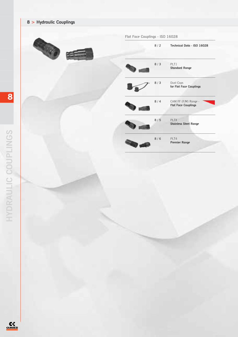
8 > Hydraulic Couplings
HYDRAULIC COUPLINGS
8
Flat Face Couplings - ISO 16028
8 / 2 Technical Data - ISO 16028
8 / 3 PLT1Standard Range
8 / 3 Dust Capsfor Flat Face Couplings
8 / 4 CAM FF (F/M) Range -Flat Face Couplings
8 / 5 PLTXStainless Steel Range
8 / 6 PLT4Premier Range
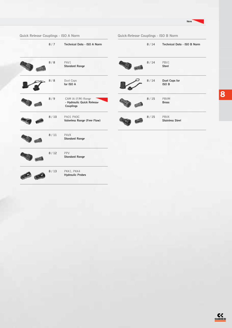
8
Quick-Release Couplings - ISO B Norm
8 / 14 Technical Data - ISO B Norm
8 / 14 PBV1 Steel
8 / 14 Dust Caps for ISO B
8 / 15 PBVMBrass
8 / 15 PBVXStainless Steel
Quick Release Couplings - ISO A Norm
8 / 7 Technical Data - ISO A Norm
8 / 8 PAV1Standard Range
8 / 8 Dust Capsfor ISO A
8 / 9 CAM IA (F/M) Range- Hydraulic Quick ReleaseCouplings
8 / 10 PAO1 PAOCValveless Range (Free Flow)
8 / 11 PAVXStandard Range
8 / 12 PPVStandard Range
8 / 13 PKK1, PKK4Hydraulic Probes
New

The company reserves the right to vary models and dimensions without notice.Products designed for industrial applications. General terms and conditions for sale are available on www.camozzi.co.uk
HYDRAULIC COUPLINGS > Technical Data UK SHORT FORM CATALOGUE > RELEASE 8.6
8
8
2
The PLK4 range of probes has been designed to offerconnection to PLT couplings under residual pressure.A full range of connections are available in BSP, Metric,NPT and UNF thread forms with tube connections from 6 to30mm tube diameters to DIN 2353. Options include lightand heavy thread forms in both short and long (Bulkhead)connections.
Applications
Flat faced couplings are particularly suitable for agriculture,construction and mobile equipment, mining and generalindustrial use.
Features
Heavy duty constructionHigh working pressures and flow rates low pressure dropsDesigned for minimal spillage during connection anddisconnectionLocking sleeve provided with safety system preventingaccidental disconnectionEasy to keep clean.
General Technical Information
Body and Probe - All steel construction, stressedcomponents nitrided or induction hardenedFinish - Zinc Plated in accordance with EEC directive2000/53/CE (Chrome 6 free)Seals - NBR standard EPDM, Viton and Neoprene onrequest. (PLTX Viton as standard)Backing Ring - TeflonSprings - C98 steel or stainless steelContact the sales office for special enquires and furthertechnical information
PLT Range - ISO 16028PLT1 Standard Range (250/350 Bar) Body size ISO 6.3 - 50CAM FF (250-320 Bar) Body size ISO 6.3 - 19PLT4 Premier Range (350/500 Bar) Body size ISO 5 - 25
PLT6 Ultra High Pressure Range (700 Bar) Body size ISO 6.3 - 10PLTX Standard Range in Stainless Steel (100/400 Bar) Body size 6.3 - 50
Hydraulic Flat Face Couplings - Technical Data - ISO 16028
Standard - Stainless Steel Min. Burst PressureNominal Size Max. Working Pressure Rated Flow Male Female Coupled Fluid SpillageDN USA ISO DN(mm) (bar) (l/m) (bar) (bar) (bar) (cc)
06 04 6.3 6.2 400 12 2610 1660 2320 0.008
13 06 10 8.7 250 23 1450 1050 1980 0.010
20 08 12.5 11 250 45 1300 1000 1670 0.012
22 10 16 12.8 250 74 1200 1000 1500 0.015
25 12 19 15 250 100 1150 1040 1480 0.020
30 16 25 18 250 189 1000 1000 1000 0.030
39 24 40 30 150 379 600 600 600 0.050
50 32 50 40 100 757 400 400 400 0.100
Standard Min. Burst PressureNominal Size Max. Working Pressure Rated Flow Male Female Coupled Fluid SpillageDN USA ISO DN(mm) (bar) (l/m) (bar) (bar) (bar) (cc)
06 04 6.3 6.1 315 12 1800 1260 1430 0.008
13 06 10 8.7 250 23 1640 1000 1610 0.010
20 08 12.5 11.2 250 45 1560 1100 1900 0.012
25 12 19 15.5 250 100 1400 1100 1400 0.020
30 16 25 18 250 189 1300 1000 1400 0.030
39 24 40 30 250 379 1290 1200 1170 0.050
50 32 50 40 250 757 see PLK4 1000 1000 0.100
Premier Min. Burst PressureNominal Size Max. Working Pressure Rated Flow Male Female Coupled Fluid SpillageDN USA ISO DN(mm) (bar) (l/m) (bar) (bar) (bar) (cc)
06 04 6.3 4 320 15 1600 1400 1500 0.005
13 06 10 6.2 250 53 1350 1250 1500 0.007
13 06 10 8.7 250 53 1350 1250 1500 0.007
20 08 12.5 11 250 98 1050 1100 1400 0.008
25 12 19 12.8 250 174 1050 1000 1200 0.009
Flat Face Couplings - PLT1 Standard Range
Flat Face Couplings - CAM FF (F/M) Range
Flat Face Couplings - PLT4 Premier Range

See full catalogue or CD rom for all dimensions.For technical advice contact our sales office or your local Camozzi distributor.
HYDRAULIC COUPLINGS > PLT1 Standard RangeUK SHORT FORM CATALOGUE > RELEASE 8.6
8
8
3
PLT1 Standard Range - Hydraulic Flat Face Couplings
Standard - Stainless Steel Min. Burst PressureNominal Size Max. Working Pressure Rated Flow Male Female Coupled Fluid SpillageDN USA ISO DN(mm) (bar) (l/m) (bar) (bar) (bar) (cc)
06 04 6.3 6.2 400 12 2610 1660 2320 0.008
13 06 10 8.7 250 23 1450 1050 1980 0.010
20 08 12.5 11 250 45 1300 1000 1670 0.012
22 10 16 12.8 250 74 1200 1000 1500 0.015
25 12 19 15 250 100 1150 1040 1480 0.020
30 16 25 18 250 189 1000 1000 1000 0.030
39 24 40 30 150 379 600 600 600 0.050
50 32 50 40 100 757 400 400 400 0.100
Flat Face Couplings - PLTX Stainless Steel Range
Technical DataCharacteristicsEasy connection and disconnection bypushing the two halves together withone hand only. The locking sleeve isprovided with safety-system whichmakes sure a perfect connection andprevents accidental disconnection. Dimension 13 (DN13) conforms toHTMA specifications. All dimensions conform to ISO 16028standard.
ThreadsBSPNPT on request
MaterialsSee page 8/2
Operating and Burst PressuresSee table page 8/2
Operating TemperatureNBR standard seals -25OC to+125OC
Special RequestsFor assistance, contact our technicaloffice or your local Camozzidistributor.Other seals available on request.
DN Dash ISO CH2 CH3 ØE L1 L2 L3 Thread Carrier Half Probe HalfSize
06 04 6.3 22 22 28 101.5 58.5 53.5 1/4 PLT1.0606.002 PLT1.0606.003
13 06 10 27 27 32 116 67.5 63.5 3/8 PLT1.1310.002 PLT1.1310.003
13 06 10 27 27 32 125 72.5 67.5 1/2 PLT1.1313.002 PLT1.1313.003
20 08 12.5 36 36 38 138.5 78.5 72 3/4 PLT1.2019.002 PLT1.2019.003
25 12 19 46 41 48 157.5 94 86 3/4 PLT1.2519.002 PLT1.2519.003
25 12 19 46 41 48 157.5 94 86 1 PLT1.2525.002 PLT1.2525.003
30 16 25 50 50 55 177 109.5 90 1 1/4 PLT1.3031.002 PLT1.3031.003
39 24 40 70 70 79 210 118.5 119.5 1 1/2 PLT1.3939.002 PLT1.3939.003
50 32 50 80 70 103 290 147.5 119.5 2 PLT1.5051.112 PLK4.5051.113
Dust Caps - for Flat Face Couplings
DIN Thread for Carrier for Probe
06 1/4 PLUG SPLT.06002 CAP SPLT.06003
13 3/8 PLUG SPLT.13002 CAP SPLT.13003
13 1/2 PLUG SPLT.13002 CAP SPLT.13003
20 3/4 PLUG SPLT.20002 CAP SPLT.20003
25 1 PLUG SPLT.25002 CAP SPLT.25003
30 1 1/4 PLUG SPLT.30002 CAP SPLT.30003
Dust Caps for Flat Face Couplings
ISO 16028
Cap
Plug
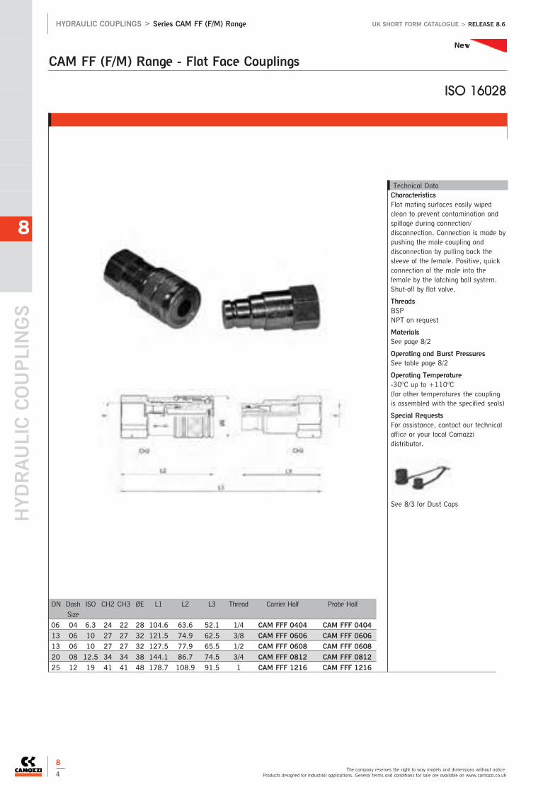
CAM FF (F/M) Range - Flat Face Couplings
HYDRAULIC COUPLINGS
The company reserves the right to vary models and dimensions without notice.Products designed for industrial applications. General terms and conditions for sale are available on www.camozzi.co.uk
HYDRAULIC COUPLINGS > Series CAM FF (F/M) Range UK SHORT FORM CATALOGUE > RELEASE 8.6
8
8
4
Technical DataCharacteristicsFlat mating surfaces easily wipedclean to prevent contamination andspillage during connection/disconnection. Connection is made bypushing the male coupling anddisconnection by pulling back thesleeve of the female. Positive, quickconnection of the male into thefemale by the latching ball system.Shut-off by flat valve.
ThreadsBSPNPT on request
MaterialsSee page 8/2
Operating and Burst PressuresSee table page 8/2
Operating Temperature-30OC up to +110OC(for other temperatures the couplingis assembled with the specified seals)
Special RequestsFor assistance, contact our technicaloffice or your local Camozzidistributor.
See 8/3 for Dust Caps
DN Dash ISO CH2 CH3 ØE L1 L2 L3 Thread Carrier Half Probe HalfSize
06 04 6.3 24 22 28 104.6 63.6 52.1 1/4 CAM FFF 0404 CAM FFF 0404
13 06 10 27 27 32 121.5 74.9 62.5 3/8 CAM FFF 0606 CAM FFF 0606
13 06 10 27 27 32 127.5 77.9 65.5 1/2 CAM FFF 0608 CAM FFF 0608
20 08 12.5 34 34 38 144.1 86.7 74.5 3/4 CAM FFF 0812 CAM FFF 0812
25 12 19 41 41 48 178.7 108.9 91.5 1 CAM FFF 1216 CAM FFF 1216
ISO 16028
New

See full catalogue or CD rom for all dimensions.For technical advice contact our sales office or your local Camozzi distributor.
HYDRAULIC COUPLINGS > Series PLTX Stainless Steel RangeUK SHORT FORM CATALOGUE > RELEASE 8.6
8
8
5
PLTX Stainless Steel Range - Hydraulic Flat Face Couplings
Technical DataCharacteristicsEasy connection and disconnection bypushing the two halves together withone hand only. The locking sleeve isprovided with safety-system whichmakes sure a perfect connection andprevents accidental disconnection. Dimension 13 (DN13) conforms toHTMA specifications. All dimensions conform to ISO 16028standard.
ThreadsBSPNPT on request
MaterialsSee page 8/3
Operating and Burst PressuresSee table page 8/3
Operating Temperaturewith Viton seals -25OC to +200OC
Special RequestsFor assistance, contact our technicaloffice or your local Camozzidistributor.
See 8/3 for Dust Caps
DN Dash ISO CH2 CH3 ØE L1 L2 L3 Thread Carrier Half Probe HalfSize
06 04 6.3 22 22 28 108 59 60 1/4 PLTX.0606.112 PLTX.0606.113
13 06 10 27 27 32 126.5 73 69.5 3/8 PLTX.1310.112 PLTX.1310.113
13 06 10 27 27 32 126 73 69 1/2 PLTX.1313.112 PLTX.1313.113
20 08 12.5 36 36 38 151 87 81.5 1/2 PLTX.2019.112 PLTX.2019.113
20 08 12.5 36 36 38 152.5 87 83 3/4 PLTX.2019.112 PLTX.2019.113
22 10 16 36 36 42 151.5 86 83 3/4 PLTX.2019.112 PLTX.2019.113
25 12 19 41 41 48 166 97.5 90.5 1 PLTX.2525.112 PLTX.2525.113
30 16 25 50 50 55 181.5 109.5 95 1 1/4 PLTX.3031.112 PLTX.3031.113
39 24 40 70 70 79 202 118 112.5 1 1/2 PLTX.3939.112 PLTX.3939.113
50 32 50 80 80 99 259 149 148 2 PLTX.5051.112 PLTX.5051.113
ISO 16028
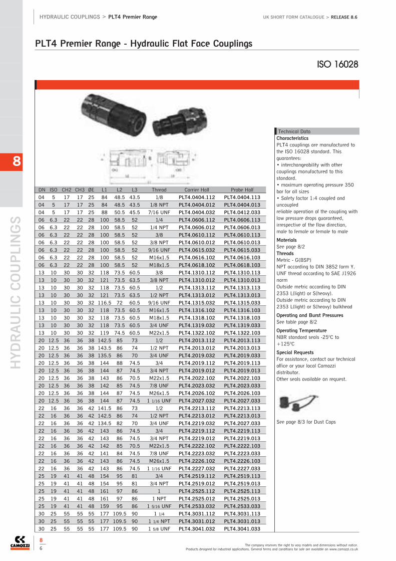
HYDRAULIC COUPLINGS
The company reserves the right to vary models and dimensions without notice.Products designed for industrial applications. General terms and conditions for sale are available on www.camozzi.co.uk
HYDRAULIC COUPLINGS > PLT4 Premier Range UK SHORT FORM CATALOGUE > RELEASE 8.6
8
8
6
PLT4 Premier Range - Hydraulic Flat Face Couplings
DN ISO CH2 CH3 ØE L1 L2 L3 Thread Carrier Half Probe Half
04 5 17 17 25 84 48.5 43.5 1/8 PLT4.0404.112 PLT4.0404.113
04 5 17 17 25 84 48.5 43.5 1/8 NPT PLT4.0404.012 PLT4.0404.013
04 5 17 17 25 88 50.5 45.5 7/16 UNF PLT4.0404.032 PLT4.0412.033
06 6.3 22 22 28 100 58.5 52 1/4 PLT4.0606.112 PLT4.0606.113
06 6.3 22 22 28 100 58.5 52 1/4 NPT PLT4.0606.012 PLT4.0606.013
06 6.3 22 22 28 100 58.5 52 3/8 PLT4.0610.112 PLT4.0610.113
06 6.3 22 22 28 100 58.5 52 3/8 NPT PLT4.0610.012 PLT4.0610.013
06 6.3 22 22 28 100 58.5 52 9/16 UNF PLT4.0615.032 PLT4.0615.033
06 6.3 22 22 28 100 58.5 52 M16x1.5 PLT4.0616.102 PLT4.0616.103
06 6.3 22 22 28 100 58.5 52 M18x1.5 PLT4.0618.102 PLT4.0618.103
13 10 30 30 32 118 73.5 60.5 3/8 PLT4.1310.112 PLT4.1310.113
13 10 30 30 32 121 73.5 63.5 3/8 NPT PLT4.1310.012 PLT4.1310.013
13 10 30 30 32 118 73.5 60.5 1/2 PLT4.1313.112 PLT4.1313.113
13 10 30 30 32 121 73.5 63.5 1/2 NPT PLT4.1313.012 PLT4.1313.013
13 10 30 30 32 116.5 72 60.5 9/16 UNF PLT4.1315.032 PLT4.1315.033
13 10 30 30 32 118 73.5 60.5 M16x1.5 PLT4.1316.102 PLT4.1316.103
13 10 30 30 32 118 73.5 60.5 M18x1.5 PLT4.1318.102 PLT4.1318.103
13 10 30 30 32 118 73.5 60.5 3/4 UNF PLT4.1319.032 PLT4.1319.033
13 10 30 30 32 119 74.5 60.5 M22x1.5 PLT4.1322.102 PLT4.1322.103
20 12.5 36 36 38 142.5 85 73 1/2 PLT4.2013.112 PLT4.2013.113
20 12.5 36 36 38 143.5 86 74 1/2 NPT PLT4.2013.012 PLT4.2013.013
20 12.5 36 36 38 135.5 86 70 3/4 UNF PLT4.2019.032 PLT4.2019.033
20 12.5 36 36 38 144 88 74.5 3/4 PLT4.2019.112 PLT4.2019.113
20 12.5 36 36 38 144 87 74.5 3/4 NPT PLT4.2019.012 PLT4.2019.013
20 12.5 36 36 38 143 86 70.5 M22x1.5 PLT4.2022.102 PLT4.2022.103
20 12.5 36 36 38 142 85 74.5 7/8 UNF PLT4.2023.032 PLT4.2023.033
20 12.5 36 36 38 144 87 74.5 M26x1.5 PLT4.2026.102 PLT4.2026.103
20 12.5 36 36 38 144 87 74.5 1 1/16 UNF PLT4.2027.032 PLT4.2027.033
22 16 36 36 42 141.5 86 73 1/2 PLT4.2213.112 PLT4.2213.113
22 16 36 36 42 142.5 86 74 1/2 NPT PLT4.2213.012 PLT4.2213.013
22 16 36 36 42 134.5 82 70 3/4 UNF PLT4.2219.032 PLT4.2027.033
22 16 36 36 42 143 86 74.5 3/4 PLT4.2219.112 PLT4.2219.113
22 16 36 36 42 143 86 74.5 3/4 NPT PLT4.2219.012 PLT4.2219.013
22 16 36 36 42 142 85 70.5 M22x1.5 PLT4.2222.102 PLT4.2222.103
22 16 36 36 42 141 84 74.5 7/8 UNF PLT4.2223.032 PLT4.2223.033
22 16 36 36 42 143 86 74.5 M26x1.5 PLT4.2226.102 PLT4.2226.103
22 16 36 36 42 143 86 74.5 1 1/16 UNF PLT4.2227.032 PLT4.2227.033
25 19 41 41 48 154 95 81 3/4 PLT4.2519.112 PLT4.2519.113
25 19 41 41 48 154 95 81 3/4 NPT PLT4.2519.012 PLT4.2519.013
25 19 41 41 48 161 97 86 1 PLT4.2525.112 PLT4.2525.113
25 19 41 41 48 161 97 86 1 NPT PLT4.2525.012 PLT4.2525.013
25 19 41 41 48 159 95 86 1 5/16 UNF PLT4.2533.032 PLT4.2533.033
30 25 55 55 55 177 109.5 90 1 1/4 PLT4.3031.112 PLT4.3031.113
30 25 55 55 55 177 109.5 90 1 1/4 NPT PLT4.3031.012 PLT4.3031.013
30 25 55 55 55 177 109.5 90 1 5/8 UNF PLT4.3041.032 PLT4.3041.033
Technical DataCharacteristicsPLT4 couplings are manufactured tothe ISO 16028 standard. Thisguarantees:• interchangeability with othercouplings manufactured to thisstandard.• maximum operating pressure 350bar for all sizes• Safety factor 1:4 coupled anduncoupledreliable operation of the coupling withlow pressure drops guaranteed,irrespective of the flow direction,male to female or female to male
MaterialsSee page 8/2ThreadsMetric - G(BSP) NPT according to DIN 3852 form Y.UNF thread according to SAE J1926normOutside metric according to DIN2353 L(light) or S(heavy).Outside metric according to DIN2353 L(light) or S(heavy) bulkhead
Operating and Burst PressuresSee table page 8/2
Operating TemperatureNBR standard seals -25OC to+125OC
Special RequestsFor assistance, contact our technicaloffice or your local Camozzidistributor.Other seals available on request.
See page 8/3 for Dust Caps
ISO 16028

Min. Burst PressureNominal Size Max. Working Pressure Rated Flow CoupledDNP USA ISO DN(mm) (bar) (l/m) (bar)
06 04 6.3 5.5 350 12 1450
10 06 10 9.5 350 23 1590
13 08 12.5 11.5 250 45 1240
20 12 20 16.5 250 106 1040
25 16 25 19 200 189 880
Quick Release Couplings - PAO1 PAOC Valveless Range (Free Flow)
See full catalogue or CD rom for all dimensions.For technical advice contact our sales office or your local Camozzi distributor.
HYDRAULIC COUPLINGS > Technical DataUK SHORT FORM CATALOGUE > RELEASE 8.6
8
8
7
The PKK range of probes has been designed to offer connectionto PPV couplings under residual pressure.A full range of connections are available in BSP, Metric andNPT thread forms with tube connections from 6 to 35mm tubediameters to DIN 2353. Options include light and heavy threadforms in both short and long (Bulkhead) connections.
Applications
ISO couplings are the most common couplings in the marketand used in all industrial applications. The PPV push - pull rangeare used extensively in agriculture.
Features
Simple and quick connectionFull interchange abilityAvailable with poppet valve or ball closing systemCompact and lightweight designValveless couplings available in zinc or chrome plated
General Technical Information
Body and Probe - All steel construction, stressed componentsnitrided or induction hardenedFinish - Zinc Plated in accordance with EEC directive2000/53/CE (Chrome 6 free)Seals - NBR standard EPDM, Viton and Neoprene on request.(SCBX Viton as standard)Backing Ring - TelfonSprings - C98 steel or stainless steelContact the sales office for special enquires and further technicalinformation
ISO 7241-1APAV1 Standard Range (160/350 Bar) Body sizes ISO 6.3 - 50PAO1 Valveless Range (200/350 Bar) Body sizes ISO 5 - 25CAM IA (F/M) Range (250/350 Bar) Body sizes ISO 6.3 - 25
PPV Push - Pull Range (225/300 Bar) Body sizes ISO 6.3 - 25SCBC Economy Range (130/350 Bar) Body sizes 6.3 - 50SCBX Stainless Steel Range (130/350 Bar) Body sizes 6.3 - 50
Hydraulic Quick Release Couplings - Technical Data - ISO A Norm
Min. Burst PressureNominal Size Max. Working Pressure Rated Flow Male Female Coupled Fluid SpillageDNP USA ISO DN(mm) (bar) (l/m) (bar) (bar) (bar) (cc)
06 04 6.3 5.5 250 12 1000 1000 1000 0.8
10 06 10 9 300 23 1340 1500 1380 1.9
13 08 12.5 10.6 225 45 930 1670 1110 2.7
20 12 20 15.7 225 106 1240 1460 1190 9.3
25 16 25 17.3 225 189 900 1170 970 16
Min. Burst PressureNominal Size Max. Working Pressure Rated Flow Male Female Coupled Fluid SpillageDNP USA ISO DN(mm) (bar) (l/m) (bar) (bar) (bar) (cc)
06 04 6.3 5 350 12 1510 1760 1450 0.5
10 06 10 9 350 23 1470 1520 1590 1.9
13 08 12.5 10.6 250 45 1000 1460 1240 2.7
20 12 20 15.7 250 106 900 1530 1040 9.3
25 16 25 17.3 200 189 1300 960 1300 16
30 20 31.5 22.8 200 288 1140 850 1090 30
39 24 40 30 190 379 810 790 820 54
50 32 50 37.6 160 757 650 960 1100 120
Quick Release Couplings - PAV1 Standard Range
Push-Pull Quick Release Couplings - PPV Standard Range
Min. Burst PressureNominal Size Max. Working Pressure Rated Flow Male Female Coupled Fluid SpillageDNP USA ISO DN(mm) (bar) (l/m) (bar) (bar) (bar) (cc)
06 04 6.3 5 350 5 2000 1500 1450 0.7
10 06 10 9 315 35 1450 1450 1300 1.4
13 08 12.5 10.6 300 75 1200 1500 1500 1.8
20 12 19 15.7 250 147 1000 1200 1000 7
25 16 25 17.3 250 250 1000 1100 1100 10.5
CAM IA (F/M) Range

HYDRAULIC COUPLINGS
The company reserves the right to vary models and dimensions without notice.Products designed for industrial applications. General terms and conditions for sale are available on www.camozzi.co.uk
HYDRAULIC COUPLINGS > Hydrulic Quick Release Couplings UK SHORT FORM CATALOGUE > RELEASE 8.6
8
8
8
PAV1 Standard Range - Hydraulic Quick Release Couplings
Technical DataMaterialSee page 8/7
Operating and Burst PressuresSee table page 8/7
Operating Temperaturewith NBR standard seals -25OC to+125OC
Special RequestsFor assistance, contact our technicaloffice or your local Camozzidistributor.Other seal available on request.
DN ISO CH2 CH3 ØE L1 L2 L3 Thread Carrier Half Probe Half
06 6.3 19 19 26 70 49 35 1/4 PAV1.0606.002 PAV1.0606.003
06 6.3 19 19 26 70 49 35 1/4 NPT PAV1.0606.012 PAV1.0606.013
10 10 22 22 30 85 60.5 42.5 3/8 PAV1.1010.002 PAV1.1010.003
10 10 22 22 30 85 60.5 42.5 3/8 NPT PAV1.1010.012 PAV1.1010.013
13 12.5 27 27 38 96 70 48 1/2 PAV1.1313.002 PAV1.1313.003
13 12.5 27 27 38 96 70 48 1/2 NPT PAV1.1313.012 PAV1.1313.013
20 20 34 34 45 114 84.5 57 3/4 PAV1.2019.002 PAV1.2019.003
20 20 34 34 45 114 84.5 57 3/4 NPT PAV1.2019.012 PAV1.2019.013
25 25 41 41 52 131 99 65.5 1 PAV1.2525.002 PAV1.2525.003
25 25 41 41 52 131 99 65.5 1 NPT PAV1.2525.012 PAV1.2525.013
30 31.5 50 50 70 150 117 75 1 1/4 PAV1.3031.002 PAV1.3031.003
30 31.5 50 50 70 150 117 75 1 1/4 NPT PAV1.3031.012 PAV1.3031.013
39 40 60 60 82 167 133 84 1 1/2 PAV1.3939.002 PAV1.3939.003
39 40 60 60 82 167 133 84 1 1/2 NPT PAV1.3939.012 PAV1.3939.013
50 50 75 75 99 216 169 108 2 PAV1.5051.002 PAV1.5051.003
50 50 75 75 99 216 169 108 2 NPT PAV1.5051.012 PAV1.5051.013
Dust Caps - for ISO ‘A’ Series
DN Carrier Half Probe Half
06 SPAV.06002 SPAV.06003
10 SPAV.10002 SPAV.10003
13 SPAV.13002 SPAV.13003
20 SPAV.20002 SPAV.20003
25 SPAV.25002 SPAV.25003
30 SPAV.30202 SPAV.30203
39 SPAV.39202 SPAV.39203
50 SPAV.50202 SPAV.50203
ISO A Norm
Dust Caps for ISO A
Cap
Plug
Min. Burst PressureNominal Size Max. Working Pressure Rated Flow Male Female Coupled Fluid SpillageDNP USA ISO DN(mm) (bar) (l/m) (bar) (bar) (bar) (cc)
13 08 12.5 10.6 250 45 1000 1460 1240 2.7
Contact the sales office for flow and pressure drop characteristics
Probes for Connection Under Pressure - PKK1, PKK4

See full catalogue or CD rom for all dimensions.For technical advice contact our sales office or your local Camozzi distributor.
HYDRAULIC COUPLINGS > CAM IA (F/M) RangeUK SHORT FORM CATALOGUE > RELEASE 8.6
8
8
9
CAM IA (F/M) Range - Hydraulic Quick Release Couplings
Stainless Steel
ISO A Norm
Technical DataCharacteristicsFlat mating surfaces easily wipedclean to prevent contamination andspillage during connection/disconnection. Connection is made bypushing the male coupling anddisconnection by pulling back thesleeve of the female. Positive, quickconnection of the male into thefemale by the latching ball system.Shut-off by flat valve.
ThreadsBSPNPT on request
MaterialsSee page 8/7
Operating and Burst PressuresSee table page 8/7
Operating Temperature-30OC up to +110OC(for other temperatures the couplingis assembled with the specified seals)
Special RequestsFor assistance, contact our technicaloffice or your local Camozzidistributor.
See page 8/8 for Dust Caps
Body ISO Dimensions Thread Carrier Half Probe Half
Size Base CH2 CH3 ØE L1 L2 L3 Size Part Number Part Number
1/4 6.3 17 17 24 69.1 48.8 34.5 1/4 CAM IAF 0404 CAM IAF 0404
3/8 10 22 22 30 80.3 57.8 40.0 3/8 CAM IAF 0606 CAM IAF 0606
1/2 12.5 27 27 38 90.2 67.0 45.0 1/2 CAM IAF 0808 CAM IAF 0808
3/4 19 34 34 45 113.3 83.5 56.5 3/4 CAM IAF 1212 CAM IAF 1212
1 25 41 41 52 129.7 97.9 64.5 1 CAM IAF 1616 CAM IAF 1616
New

HYDRAULIC COUPLINGS
The company reserves the right to vary models and dimensions without notice.Products designed for industrial applications. General terms and conditions for sale are available on www.camozzi.co.uk
HYDRAULIC COUPLINGS > PAO1 PAOC Valvesless Range (Free Flow) UK SHORT FORM CATALOGUE > RELEASE 8.6
8
8
10
PAO1 PAOC Valveless Range (Free Flow) - Hydraulic Quick Release Couplings
ISO A Norm
Technical DataMaterialPAO1 series zinc plated and yellowbichromated. PAOC series chromium-plated. All high stressed componentscarbonitrided or hardened byinductionSeals: PAO1 model standard in nitrileNBR. PAOC model standard in FPM(VitonTM). On request EPDM and CR(Neoprene) sealsBack-up Ring: In pure Teflon
Operating and Burst PressuresSee table page 8/7
Operating TemperaturePAO1 with NBR standard seals -25OCto +125OCPAOC with Viton standard seals -25OC to +200OC
Special RequestsFor assistance, contact our technicaloffice or your local Camozzidistributor.
See page 8/8 for Dust Caps
Zinc Passivated
DN ISO CH2 CH3 ØE L1 L2 L3 Thread Carrier Half Probe Half
06 6.3 19 19 26 70 49 35 1/4 PAO1.0606.002 PAO1.0606.003
06 6.3 19 19 26 70 49 35 1/4 NPT PAO1.0606.012 PAO1.0606.013
10 10 22 22 30 85 60.5 42.5 3/8 PAO1.1010.002 PAO1.1010.003
10 10 22 22 30 85 60.5 42.5 3/8 NPT PAO1.1010.012 PAO1.1010.013
13 12.5 27 27 38 96 70 48 1/2 PAO1.1313.002 PAO1.1313.003
13 12.5 27 27 38 96 70 48 1/2 NPT PAO1.1313.012 PAO1.1313.013
13 12.5 27 27 38 96 70 48 M 22x1.5 PAO1.1322.102 PAO1.1322.103
20 20 34 34 45 114 84.5 57 3/4 PAO1.2019.002 PAO1.2019.003
20 20 34 34 45 114 84.5 57 3/4 NPT PAO1.2019.012 PAO1.2019.013
25 25 41 41 52 131 99 65.5 1 PAO1.2525.002 PAO1.2525.003
25 25 41 41 52 131 99 65.5 1 NPT PAO1.2525.012 PAO1.2525.013
Chromium Plated
10 10 22 22 30 85 60.5 42.5 3/8 PAOC.1010.002 PAOC.1010.003
13 12.5 27 27 38 96 70 48 1/2 PAOC.1313.002 PAOC.1313.003
20 20 34 34 45 114 84.5 57 3/4 PAOC.2019.002 PAOC.2019.003

See full catalogue or CD rom for all dimensions.For technical advice contact our sales office or your local Camozzi distributor.
HYDRAULIC COUPLINGS > PAVX Standard RangeUK SHORT FORM CATALOGUE > RELEASE 8.6
8
8
11
PAVX Standard Range - Hydraulic Quick Release Couplings
Stainless Steel
ISO A Norm
Technical DataMaterialStainless Steel - AISI 316. Springs - AISI 302Seals - NBR standardBack-up Ring: In pure Teflon
Operating Temperaturewith NBR standard seals -25OC to+125OCwith Viton seals -25OC to +200OC
Special RequestsFor assistance, contact our technicaloffice or your local Camozzidistributor.
See page 8/8 for Dust Caps
Body ISO Dimensions Thread Carrier Half Probe Half
Size Base CH2 CH3 ØE L1 L2 L3 BAR Size Part Number Part Number
1/4 6.3 19 19 26 72 51 36 350 1/4 PAVX.0606.002 PAVX. 0606.003
3/8 10 24 22 32 81 58.5 40.5 250 3/8 PAVX.1010.002 PAVX. 1010.003
1/2 12.5 30 27 38 87.5 63.5 46 250 1/2 PAVX.1313.002 PAVX. 1313.003
3/4 20 38 36 46 112 83.5 56 200 3/4 PAVX.2019.002 PAVX. 2019.003
1 25 46 41 55 126 97 63 150 1 PAVX.2525.002 PAVX. 2525.003
1 1/4 31.5 60 50 70 150 117 75 63 *1 1/4 PAVX.3031.002 PAVX. 3031.003
1 1/2 40 70 60 84.5 167 133 83.5 50 *1 1/2 PAVX.3939.002 PAVX. 3939.003
2 50 75 75 100 210 165 105 50 *2 PAVX.5051.002 PAVX. 5051.003
* Not ISO A Standard
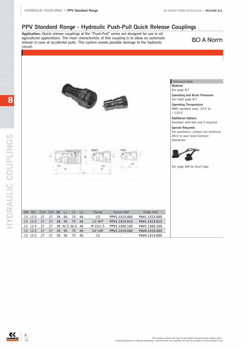
HYDRAULIC COUPLINGS
The company reserves the right to vary models and dimensions without notice.Products designed for industrial applications. General terms and conditions for sale are available on www.camozzi.co.uk
HYDRAULIC COUPLINGS > PPV Standard Range UK SHORT FORM CATALOGUE > RELEASE 8.6
8
8
12
Application: Quick release couplings of the “Push-Pull” series are designed for use in allagricultural applications. The main characteristic of this coupling is to allow an automaticrelease in case of accidental pulls. This system avoids possible damage to the hydrauliccircuit.
PPV Standard Range - Hydraulic Push-Pull Quick Release Couplings
Technical DataMaterialSee page 8/7
Operating and Burst PressuresSee table page 8/7
Operating TemperatureNBR standard seals -25OC to+125OC
Additional OptionsAvailable with ball seal if required
Special RequestsFor assistance, contact our technicaloffice or your local Camozzidistributor.
See page 8/8 for Dust Caps
DN ISO CH2 CH3 ØE L1 L2 L3 Thread Carrier Half Probe Half
13 12.5 27 27 38 96 70 48 1/2 PPV1.1313.002 PAV1.1313.003
13 12.5 27 27 38 96 70 48 1/2 NPT PPV1.1313.012 PAV1.1313.013
13 12.5 27 27 38 92.5 66.5 48 M 22x1.5 PPV1.1322.102 PAV1.1322.103
13 12.5 27 27 38 96 70 48 3/4 UNF PPV1.1319.032 PAV4.1319.033
13 12.5 27 27 38 96 70 48 1/2 - PAV4.1313.003
ISO A Norm
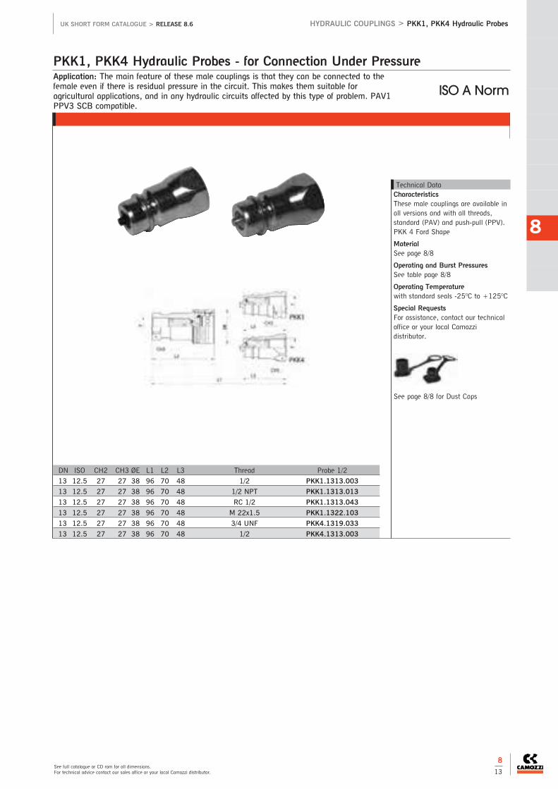
See full catalogue or CD rom for all dimensions.For technical advice contact our sales office or your local Camozzi distributor.
HYDRAULIC COUPLINGS > PKK1, PKK4 Hydraulic ProbesUK SHORT FORM CATALOGUE > RELEASE 8.6
8
8
13
Application: The main feature of these male couplings is that they can be connected to thefemale even if there is residual pressure in the circuit. This makes them suitable foragricultural applications, and in any hydraulic circuits affected by this type of problem. PAV1PPV3 SCB compatible.
PKK1, PKK4 Hydraulic Probes - for Connection Under Pressure
Technical DataCharacteristicsThese male couplings are available inall versions and with all threads,standard (PAV) and push-pull (PPV).PKK 4 Ford Shape
MaterialSee page 8/8
Operating and Burst PressuresSee table page 8/8
Operating Temperaturewith standard seals -25OC to +125OC
Special RequestsFor assistance, contact our technicaloffice or your local Camozzidistributor.
See page 8/8 for Dust Caps
DN ISO CH2 CH3 ØE L1 L2 L3 Thread Probe 1/2
13 12.5 27 27 38 96 70 48 1/2 PKK1.1313.003
13 12.5 27 27 38 96 70 48 1/2 NPT PKK1.1313.013
13 12.5 27 27 38 96 70 48 RC 1/2 PKK1.1313.043
13 12.5 27 27 38 96 70 48 M 22x1.5 PKK1.1322.103
13 12.5 27 27 38 96 70 48 3/4 UNF PKK4.1319.033
13 12.5 27 27 38 96 70 48 1/2 PKK4.1313.003
ISO A Norm
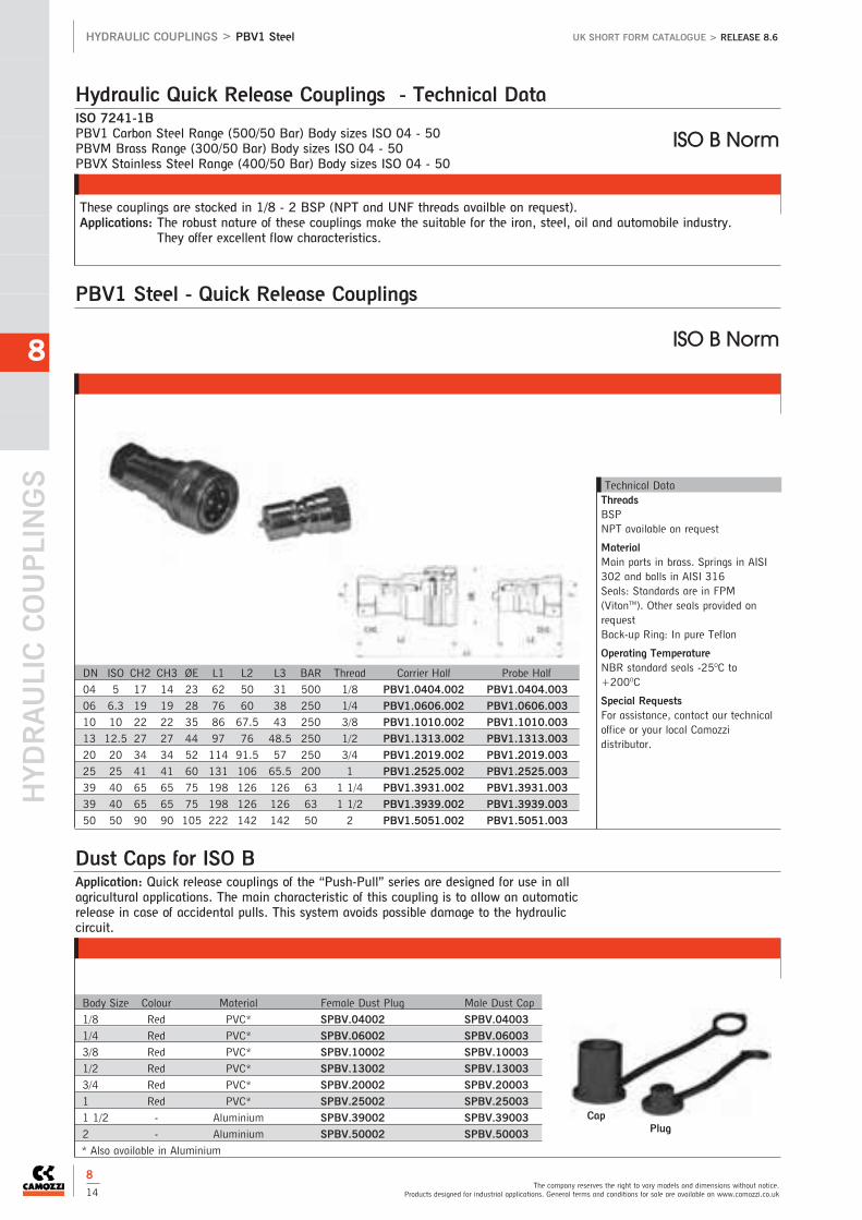
HYDRAULIC COUPLINGS
The company reserves the right to vary models and dimensions without notice.Products designed for industrial applications. General terms and conditions for sale are available on www.camozzi.co.uk
HYDRAULIC COUPLINGS > PBV1 Steel UK SHORT FORM CATALOGUE > RELEASE 8.6
8
PBV1 Steel - Quick Release Couplings
Technical DataThreadsBSPNPT available on request
MaterialMain parts in brass. Springs in AISI302 and balls in AISI 316Seals: Standards are in FPM(VitonTM). Other seals provided onrequestBack-up Ring: In pure Teflon
Operating TemperatureNBR standard seals -25OC to+200OC
Special RequestsFor assistance, contact our technicaloffice or your local Camozzidistributor.
DN ISO CH2 CH3 ØE L1 L2 L3 BAR Thread Carrier Half Probe Half
04 5 17 14 23 62 50 31 500 1/8 PBV1.0404.002 PBV1.0404.003
06 6.3 19 19 28 76 60 38 250 1/4 PBV1.0606.002 PBV1.0606.003
10 10 22 22 35 86 67.5 43 250 3/8 PBV1.1010.002 PBV1.1010.003
13 12.5 27 27 44 97 76 48.5 250 1/2 PBV1.1313.002 PBV1.1313.003
20 20 34 34 52 114 91.5 57 250 3/4 PBV1.2019.002 PBV1.2019.003
25 25 41 41 60 131 106 65.5 200 1 PBV1.2525.002 PBV1.2525.003
39 40 65 65 75 198 126 126 63 1 1/4 PBV1.3931.002 PBV1.3931.003
39 40 65 65 75 198 126 126 63 1 1/2 PBV1.3939.002 PBV1.3939.003
50 50 90 90 105 222 142 142 50 2 PBV1.5051.002 PBV1.5051.003
ISO B Norm
ISO 7241-1BPBV1 Carbon Steel Range (500/50 Bar) Body sizes ISO 04 - 50PBVM Brass Range (300/50 Bar) Body sizes ISO 04 - 50PBVX Stainless Steel Range (400/50 Bar) Body sizes ISO 04 - 50
These couplings are stocked in 1/8 - 2 BSP (NPT and UNF threads availble on request).Applications: The robust nature of these couplings make the suitable for the iron, steel, oil and automobile industry.
They offer excellent flow characteristics.
Hydraulic Quick Release Couplings - Technical Data
ISO B Norm
Application: Quick release couplings of the “Push-Pull” series are designed for use in allagricultural applications. The main characteristic of this coupling is to allow an automaticrelease in case of accidental pulls. This system avoids possible damage to the hydrauliccircuit.
Dust Caps for ISO B
Body Size Colour Material Female Dust Plug Male Dust Cap
1/8 Red PVC* SPBV.04002 SPBV.04003
1/4 Red PVC* SPBV.06002 SPBV.06003
3/8 Red PVC* SPBV.10002 SPBV.10003
1/2 Red PVC* SPBV.13002 SPBV.13003
3/4 Red PVC* SPBV.20002 SPBV.20003
1 Red PVC* SPBV.25002 SPBV.25003
1 1/2 - Aluminium SPBV.39002 SPBV.39003
2 - Aluminium SPBV.50002 SPBV.50003
* Also available in Aluminium
CapPlug
8
14
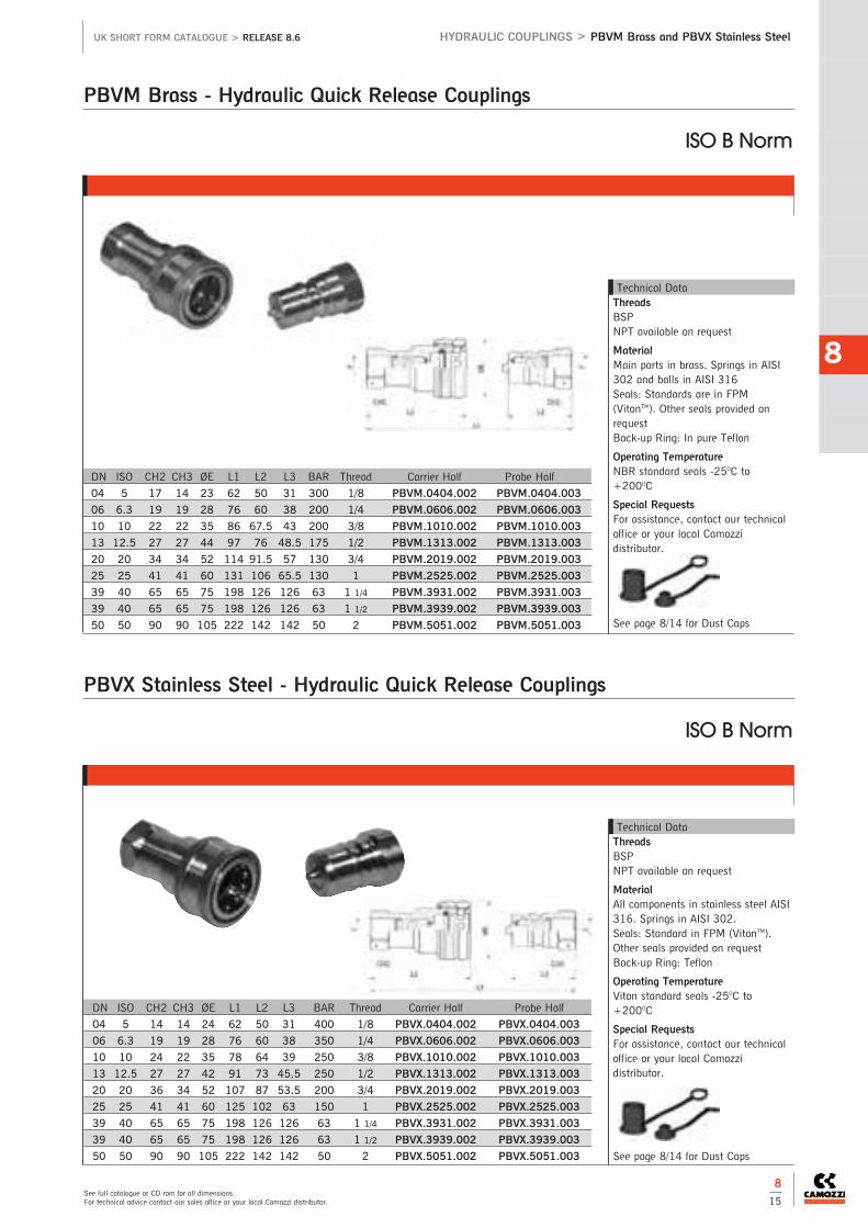
See full catalogue or CD rom for all dimensions.For technical advice contact our sales office or your local Camozzi distributor.
HYDRAULIC COUPLINGS > PBVM Brass and PBVX Stainless SteelUK SHORT FORM CATALOGUE > RELEASE 8.6
8
8
15
PBVM Brass - Hydraulic Quick Release Couplings
Technical DataThreadsBSPNPT available on request
MaterialMain parts in brass. Springs in AISI302 and balls in AISI 316Seals: Standards are in FPM(VitonTM). Other seals provided onrequestBack-up Ring: In pure Teflon
Operating TemperatureNBR standard seals -25OC to+200OC
Special RequestsFor assistance, contact our technicaloffice or your local Camozzidistributor.
See page 8/14 for Dust Caps
Technical DataThreadsBSPNPT available on request
MaterialAll components in stainless steel AISI316. Springs in AISI 302.Seals: Standard in FPM (VitonTM).Other seals provided on requestBack-up Ring: Teflon
Operating TemperatureViton standard seals -25OC to+200OC
Special RequestsFor assistance, contact our technicaloffice or your local Camozzidistributor.
See page 8/14 for Dust Caps
DN ISO CH2 CH3 ØE L1 L2 L3 BAR Thread Carrier Half Probe Half
04 5 14 14 24 62 50 31 400 1/8 PBVX.0404.002 PBVX.0404.003
06 6.3 19 19 28 76 60 38 350 1/4 PBVX.0606.002 PBVX.0606.003
10 10 24 22 35 78 64 39 250 3/8 PBVX.1010.002 PBVX.1010.003
13 12.5 27 27 42 91 73 45.5 250 1/2 PBVX.1313.002 PBVX.1313.003
20 20 36 34 52 107 87 53.5 200 3/4 PBVX.2019.002 PBVX.2019.003
25 25 41 41 60 125 102 63 150 1 PBVX.2525.002 PBVX.2525.003
39 40 65 65 75 198 126 126 63 1 1/4 PBVX.3931.002 PBVX.3931.003
39 40 65 65 75 198 126 126 63 1 1/2 PBVX.3939.002 PBVX.3939.003
50 50 90 90 105 222 142 142 50 2 PBVX.5051.002 PBVX.5051.003
DN ISO CH2 CH3 ØE L1 L2 L3 BAR Thread Carrier Half Probe Half
04 5 17 14 23 62 50 31 300 1/8 PBVM.0404.002 PBVM.0404.003
06 6.3 19 19 28 76 60 38 200 1/4 PBVM.0606.002 PBVM.0606.003
10 10 22 22 35 86 67.5 43 200 3/8 PBVM.1010.002 PBVM.1010.003
13 12.5 27 27 44 97 76 48.5 175 1/2 PBVM.1313.002 PBVM.1313.003
20 20 34 34 52 114 91.5 57 130 3/4 PBVM.2019.002 PBVM.2019.003
25 25 41 41 60 131 106 65.5 130 1 PBVM.2525.002 PBVM.2525.003
39 40 65 65 75 198 126 126 63 1 1/4 PBVM.3931.002 PBVM.3931.003
39 40 65 65 75 198 126 126 63 1 1/2 PBVM.3939.002 PBVM.3939.003
50 50 90 90 105 222 142 142 50 2 PBVM.5051.002 PBVM.5051.003
ISO B Norm
PBVX Stainless Steel - Hydraulic Quick Release Couplings
ISO B Norm

9 > Hydraulic Valves & Accessories
HYDRAULIC VALVES & ACCESSORIES
9
Hydraulic Ball Valves
9 / 2 High Pressure 2-Way Ball Valves
9 / 3 Ultra High PressureBall Valves
9 / 3 High Pressure 3-Way DiverterBall Valves
9 / 4 High Pressure Ball Valves(with fixing holes)
9 / 5 316 Stainless Steel High Pressure Ball Valves

9
Accessories
9 / 6 In-Line Check Valves
9 / 7-8 Flow Control & Needle Valves
9 / 9 Pressure Test Kits

Part Number: SKH.* - SKH Series, Forged Steel
High Pressure 2-Way Ball Valves
HYDRAULIC VALVES & ACCESSORIES
The company reserves the right to vary models and dimensions without notice.Products designed for industrial applications. General terms and conditions for sale are available on www.camozzi.co.uk
HYDRAULIC VALVES & ACCESSORIES > High Pressure 2 Way Ball Valves
9Technical DataMaterialsCarbon steel, black phosphated,Polyamide/BUNA seals
Operating PressureSee table
Safety Factor1.5
Operating Temperature-30OC - to +90OC
Additional OptionsForged steel bodies, DELRIN/BUNA,VITON, EPDM and PTFE seals
Special RequestsFor assistance, contact our technicaloffice or your local Camozzidistributor.
Part Number: BKH.* - BKH Series, Barstock Steel
BSP (G), NPT (N), METRIC THREADS (L&S)
DN Bore Thread BAR BSP Code NPT Code
4 5 1/8 500 *1113 G18 *1113 N18
6 6 1/4 500 *1113 G14 *1113 N14
10 10 3/8 500 *1113 G38 *1113 N38
13 13 1/2 500 *1113 G1213 *1113 N12
16 15 1/2 500 *1113 G1215 -
20 20 3/4 400 *1113 G34 *1113 N34
25 24 1 350 *1113 G1 *1113 N1
32 24 1 1/4 350 *1113 G54 *1113 N54
40 24 1 1/2 350 *1113 G32 *1113 N32
Outside metric according to DIN 2353 L (light) or S (heavy)
Code Tube Size Light Code Tube Size Heavy
4 5 - M12 x 1.5 500 *1113 6L - -
6 6 - M14 x 1.5 500 *1113 8L - -
8 8 5 M16 x 1.5 500 *1113 10L *1113 8S
10 10 6 M18 x 1.5 500 *1113 12L *1113 10S
10 - 8 M20 x 1.5 500 - *1113 12S
13 13 10 M22 x 1.5 500 *1113 15L *1113 14S
13 - 13 M24 x 1.5 500 - *1113 16S
16 15 - M26 x 1.5 500 *1113 18L *1113 20S
20 20 15 M30 x 2 400 *1113 22L *1113 20S
25 24 20 M36 x 2 350 *1113 28L *1113 25S
25 - 24 M42 x 2 350 - *1113 30S
32 24 - M45 x 2 350 *1113 35L -
40 24 24 M52 x 2 350 *1113 42L *1113 38S
UK SHORT FORM CATALOGUE > Release 8.6
9
2
BSP (G), NPT (N), METRIC THREADS (L&S)
DN Bore Thread BAR BSP Code NPT Code
32 32 1 1/4 420 *3123 G54 *2123 N54
40 38 1 1/2 420 *3123 G32 *3123 N32
50 48 2 420 *3123 G2-2PC *3123 N2
50 48 2 420 *1113 G2-3PC -
Code Tube Size Light Code Tube Size Heavy
32 32 M45 x 2 420 *2123 35L *2123 38S
40 38 M52 x 2 420 *2123 42L -

Connections: NPT Female1/4 - 1 1/2 Female
Ultra High Pressure Ball Valves
See full catalogue or CD rom for all dimensions.For technical advice contact our sales office or your local Camozzi distributor.
HYDRAULIC VALVES & ACCESSORIES > Ultra High Pressure Ball Valves
9Technical DataMaterialsCarbon steel, stainless steel,Polyamide/BUNA seals
Operating PressureSee table
Operating Temperature-30OC - to +90OC
Special RequestsFor assistance, contact our technicaloffice or your local Camozzidistributor.
Technical DataMaterialsCarbon steel, black phosphated,DELRIN/BUNA seals
Operating PressureSee table
Operating Temperature-30OC - to +90OC
Special RequestsFor assistance, contact our technicaloffice or your local Camozzidistributor.
Part Number: HRKH* - HRKH Series
DN Bore Thread BAR Carbon Steel Stainless Steel
6 6 1/4 800 *3723 N14 *4423 N14
10 6 3/8 800 *3723 N38 *4423 N38
13 9 1/2 800 *3723 N12 *4423 N12
20 13 3/4 800 *3723 N34 *4423 N34
25 17 1 800 *3723 N1 *4423 N1
40 40 1 1/2 700 *3723 N112 *4423 N112
UK SHORT FORM CATALOGUE > Release 8.6
9
3
Part Number: SK3* - SK3 Series, Forged Steel
DN Bore Thread BAR Code BSP Code NPT
20 18 3/4 350 *2123 G34 *2123 N34
25 22 1 350 *2123 G1 *2123 N1
32 22 1 1/4 350 *2123 G5425 *2123 N5425
32 30 1 1/4 350 *2123 G5425 *2123 N5432
40 25 1 1/2 350 *2123 G3225 *2123 N3225
40 35 1 1/2 350 *2123 G3240 *2123 N3240
50 44 2 350 *2123 G2 *2123 N2
Part Number: BK3* - BK3 Series, Barstock Steel
DN Bore Thread BAR Code BSP Code NPT
4 4 1/8 400 *1123 G18 -
6 6 1/4 400 *1123 G14 *1123 N14
10 9 3/8 400 *1123 G38 *1123 N38
13 12 1/2 350 *1123 G12 *1123 N12
High Pressure 3-way Diverter Ball Valves

HYDRAULIC VALVES & ACCESSORIES
The company reserves the right to vary models and dimensions without notice.Products designed for industrial applications. General terms and conditions for sale are available on www.camozzi.co.uk
HYDRAULIC VALVES & ACCESSORIES > High Pressure Ball Valves
9
UK SHORT FORM CATALOGUE > Release 8.6
9
4
Connections: 1/4 - 1 1/2 BSP Female
High Pressure Ball Valves (with fixing holes)
Technical DataMaterialsCarbon steel, zinc passivated, BUNA
Operating PressureSee table
Operating Temperature-20OC - to +100OC
Special RequestsFor assistance, contact our technicaloffice or your local Camozzidistributor.
Part Number: VF3* - VF3 Series 3-Way L or T
DN Thread BAR Carbon Steel
6 1/4 500 *1113 G14
10 3/8 500 *1113 G38
13 1/2 500 *1113 G12
20 3/4 250 *1113 G34
25 1 250 *1113 G1
25 1 1/4 250 *1113 G54
25 1 1/2 250 *1113 G32
Part Number: VF2* - VF2 Series 2-Way
DN Thread BAR Carbon Steel
6 1/4 500 *1113 G14
10 3/8 500 *1113 G38
13 1/2 500 *1113 G12
20 3/4 320 *1113 G34
25 1 320 *1113 G1
25 1 1/4 320 *1113 G54
25 1 1/2 320 *1113 G32

UK SHORT FORM CATALOGUE > Release 8.6
9
5
316 Stainless Steel High Pressure Ball Valves
See full catalogue or CD rom for all dimensions.For technical advice contact our sales office or your local Camozzi distributor.
HYDRAULIC VALVES & ACCESSORIES > 316 Stainless Steel High Pressure Ball Valves
9Technical DataMaterials316 stainless steel, DELRIN, BUNAseals
Operating PressureSee table
Operating Temperature-30OC - to +90OC
Special RequestsFor assistance, contact our technicaloffice or your local Camozzidistributor.
Part Number: RKH* - RKH Series, Full Bore
DN Bore Thread BAR Code BSP Code NPT
6 6 1/4 400 *4423 G14 *4423 N14
10 10 3/8 400 *4423 G38 *4423 N38
13 13 1/2 400 *4423 G12 *4423 N12
20 20 3/4 400 *4423 G34 *4423 N34
25 24 1 400 *4423 G1 *4423 N1
25 24 1 1/4 400 *4423 G5425 *4423 N5425
25 24 1 1/2 400 *4423 G3525 *4423 N3225
32 32 1 1/4 350 *4423 G5432 *4423 N5432
40 38 1 1/2 350 *4423 G3240 *4423 N3240
50 48 2 350 *4423 G2 *4423 N2

In-Line Check Valves
HYDRAULIC VALVES & ACCESSORIES
The company reserves the right to vary models and dimensions without notice.Products designed for industrial applications. General terms and conditions for sale are available on www.camozzi.co.uk
HYDRAULIC VALVES & ACCESSORIES > In-Line Check Valves
9Technical DataMaterialsFT 260/6: Black Carbon SteelATR Series: Yellow Carbon SteelFT 2260: Stainless Steel/VITONATR-X: Stainless Steel (316)
Cracking PressureFT: 0.35 BAR or 4.5 BARATR: 0.35/1.5/2.5/4/6 BAR
Operating Temperature-20OC - to +100OC
Special RequestsFor assistance, contact our technicaloffice or your local Camozzidistributor.
FT 260/6 - Ball type closure - Carbon Steel
Thread PN BAR Carbon Steel/Buna
1/8 350 FT260/6-G18
1/4 350 FT260/6-G14
3/8 350 FT260/6-G38
1/2 350 FT260/6-G12
3/4 350 FT260/6-G34
1 350 FT260/6-G100
ATR Series - Metal to Metal Seal - Carbon Steel*
Thread PN BAR Carbon Steel/Buna
1/8 300 ATR-G18
1/4 300 ATR-G14
3/8 300 ATR-G38
1/2 300 ATR-G12
3/4 300 ATR-G34
1 300 ATR-G100
1 1/4 300 ATR-G114
1 1/2 300 ATR-G112
2 200 ATR-G200
*Standard spring 5psi, for other options contact the sales office
UK SHORT FORM CATALOGUE > Release 8.6
9
6

Connections: 1/8 - 11/2 BSP
Inline needle valves with micrometer scale
Flow Control & Needle Valves
See full catalogue or CD rom for all dimensions.For technical advice contact our sales office or your local Camozzi distributor.
HYDRAULIC VALVES & ACCESSORIES > Flow Control & Needle Valves
9Technical DataMaterialsDV/DRV: Carbon steel, Nitrile sealsFT: Nickel plated brass (stainlesssteel where stated), Nitrile seals
Operating PressureDV/DRV: 350 BARFT: 210 BAR
Operating Temperature-20OC - to +100OC
Special RequestsFor assistance, contact our technicaloffice or your local Camozzidistributor.
DV Series, Double Acting Flow Control & Shut-off (Bi-directional)
DRV Series, Single Acting Flow Control, Free reverse Flow (Uni-directional)
Part Number BSP BAR LPM MAX
DV-G18 1/8 350 10
DV-G14 1/4 350 50
DV-G38 3/8 350 75
DV-G12 1/2 350 140
DV-G34 3/4 350 175
DV-G100 1 350 350
DV-G114 1 1/4 350 350
DV-G112 1 1/2 350 350
Part Number BSP BAR LPM MAX
DRV-G18 1/8 350 10
DRV-G14 1/4 350 50
DRV-G38 3/8 350 75
DRV-G12 1/2 350 140
DRV-G34 3/4 350 175
DRV-G100 1 350 350
DRV-G114 1 1/4 350 350
DRV-G112 1 1/2 350 350
DRV-G200 2 350 350
UK SHORT FORM CATALOGUE > Release 8.6
9
7

Flow Control & Needle Valves
HYDRAULIC VALVES & ACCESSORIES
The company reserves the right to vary models and dimensions without notice.Products designed for industrial applications. General terms and conditions for sale are available on www.camozzi.co.uk
HYDRAULIC VALVES & ACCESSORIES > Flow Control & Needle Valves
9
Bi-directional Flow control & shut off Part Number Part Number
BSP BAR LPM Brass Stainless Steel
1/8 210 10 FT 1251/2-18 -
1/4 210 20 FT 1251/2-14 FT 2251/2-14
3/8 210 30 FT 1251/2-38 FT 2251/2-38
1/2 210 60 FT 1251/2-12 FT 2251/2-12
3/4 210 80 FT 1251/2-34 FT 2251/2-34
Bi-directional 90O Mount Flow control & shut off Part Number
BSP BAR LPM Brass
1/8 210 10 FT 1252/2-18
1/4 210 20 FT 1252/2-14
3/8 210 30 FT 1252/2-38
1/2 210 60 FT 1252/2-12
Uni-directional Flow control Part Number
BSP BAR LPM Brass
1/8 210 10 FT 1253/5-18
1/4 210 20 FT 1253/5-14
3/8 210 30 FT 1253/5-38
1/2 210 60 FT 1253/5-12
3/4 210 80 FT 1253/5-34
Uni-directional 90O Mount Flow control Part Number
BSP BAR LPM Brass
1/8 210 10 FT 1254/5-18
1/4 210 20 FT 1254/5-14
3/8 210 30 FT 1254/5-38
1/2 210 60 FT 1254/5-12
Bi-directional Fine flow control Part Number
BSP BAR LPM Brass
1/8 210 0-3 fine control FT 1237/2-18
Uni-directional Fine flow control Part Number
BSP BAR LPM Brass
1/8 210 0-3 fine control FT 1237/5-18
Uni-directional Flow control Part Number
BSP BAR LPM Brass
1/4 210 20 FT 1251/5-14
3/8 210 30 FT 1251/5-38
1/2 210 60 FT 1251/5-12
3/4 210 80 FT 1251/5-34
UK SHORT FORM CATALOGUE > Release 8.6
9
8

Contains:N.1 Plastic box > KP1N.2 Glycerine-filled pressure gauges > D.63N.1 Micro-hose > 6400-10.162-50.204-2000mm
Pressure Test Kits
See full catalogue or CD rom for all dimensions.For technical advice contact our sales office or your local Camozzi distributor.
HYDRAULIC VALVES & ACCESSORIES > Pressure Test Kits
9Order Code750.KP1 + indicate the scale of thegauge.Available Scales0-6, 0-10, 0-25, 0-40, 0-60, 0-100,0-160, 0-250, 0-400, 0-600
Dimensions240 x 200 x 240mm
750.KP1 (+ scale)
Order Code750.KP2 + indicate the scale of thegauge.Available Scales0-6, 0-10, 0-25, 0-40, 0-60, 0-100,0-160, 0-250, 0-400, 0-600
Dimensions390 x 260 x 80mm
750.KP2 (+ scale)
Contains:N.1 Plastic box > KP2N.2 Glycerine-filled pressure gauges > D.63N.2 Test points > 620.01.204.21 1/4N.1 Micro-hose > 6400-10.162-10.162-2000mmN.2 Pressure gauges connections > 620.08.204.00 1/4 BSPN.1 Pressure gauge adaptor > 620.09.204.00 1/4 BSPN.1 Reducer > 630.01.206.10 3/8 M8x1N.1 Reducer > 630.01.208.20 1/2 M10x1N.1 Test point > 620.01.008.01 M8x1N.1 Test point > 620.01.010.01 M10x1
Contains:N.1 Plastic box > KP1N.2 Glycerine-filled pressure gauges > D.63N.1 Micro-hose > 6400-10.162-10.162-2000mm
UK SHORT FORM CATALOGUE > Release 8.6
9
9

10 > Tubing
TUBING
10
Nylon
10 / 2 Flexible and Extra Flexible Nylon Tubing
10 / 3 C-Truck Air Brake Nylon Tubing
10 / 4 Flexible Nylon Recoils

10
PTFE Tubing
10 / 8 PTFE Tubing
Accessories
10 / 8 Tube Cutters andClamps
PVC Hose
10 / 5 Reinforced PVC Braided Hose
10 / 6 PVC Hose
10 / 7 PV Tubing
10 / 7 Pneumatic Polyurethane Tubing
Pneumatic Polyurethane Tubing

TUBING
The company reserves the right to vary models and dimensions without notice.Products designed for industrial applications. General terms and conditions for sale are available on www.camozzi.co.uk
TUBING > Flexible and Extra Flexible Nylon Tubing
10
10
2
UK SHORT FORM CATALOGUE > RELEASE 8.6
30m coil (BS5409)
Applications: Both flexible and extra flexible nylon tubing is manufactured from highquality nylon granules.These are ideally suited for use with push-in fittings and for a wide range of industrialapplications. Compressed air, lubrication, refrigeration, air conditioning, coolant lines, fuels and oils(TRN and TRM).Pneumatic controls and instrumentation systems (TRXN).
Flexible and Extra Flexible Nylon Tubing
Flexible Nylon Tubing - Metric OD ID Working Working
mm mm Pressure psi Pressure bar
TRN 4/2.5* 4 2.5 400 27
TRN 4/3# 4 3 260 18
TRN 5/3* 5 3 400 24
TRN 6/4* 6 4 350 24
TRN 8/5.5* 8 5.5 335 23
TRN 8/6* 8 6 255 17
TRN 10/7* 10 7 320 22
TRN 10/8* 10 8 200 14
TRN 12/9* 12 9 260 18
TRN 12/10* 12 10 160 11
TRN 14/11† 14 11 210 14
TRN 15/12.5† 14 12.5 195 13
TRN 16/13# 16 13 200 14
TRN 22/17# 22 17 235 16
TRN 28/22# 28 22 220 15
Technical DataStandard Coil Lengths30 metresOther lengths and drums available onrequest
MaterialsManufactured from nylon 11 or 12
Operating Temperature-35oC to +70oC Brittle temperature: -70oC
Working PressureValues stated are based on the shortterm burst pressure of nylon at 20oCusing a 4:1 safety factor.For data over 20oC, contact our salesoffice
Bend RadiusFor information regarding this data,contact our sales office
Chemical ResistanceResistant to most solvents, alkalis,oils, greases, petroleum products, anddilute acids (mineral and organic).For further information, contact oursales office
ApprovalsManufactured to BS5409 (1 and 2)This product range is not suitable forfood and drinks applications - seepage 10/6
Technical AdviceFor assistance, contact our technicaloffice or your local Camozzidistributor.
*TRN, TRM and TRXN tubing is supplied in natural as standard. The tube sizes marked *are available in natural, black, red, blue, green and yellow. Please specify colour whenordering.#Only available in natural.†Only available in natural or blue.
Flexible Nylon Tubing - Imperial OD ID Working Working
inch inch Pressure psi Pressure bar
TRM 1/8# 1/8 .058 350 23
TRM 3/16* 3/16 .117 350 23
TRM 1/4* 1/4 .170 350 23
TRM 5/16* 5/16 .212 350 23
TRM 3/8* 3/8 .250 350 23
TRM 1/2* 1/2 .375 250 17
TRM 5/8# 5/8 .5 200 13
TRM 3/4# 3/4 .594 200 13
TRM 1# 1 .813 200 13
Extra Flexible Nylon Tubing - Metric OD ID Working Working
mm mm Pressure psi Pressure bar
TRXN 4/2.5* 4 2.5 220 15
TRXN 5/3# 5 3 250 17
TRXN 6/4* 6 4 200 13
TRXN 8/5.5# 8 5.5 160 11
TRXN 10/7# 10 7 160 11
TRXN 12/8.5* 12 8.5 130 9

Supplied in black as standard. The tube sizes marked * are also available in natural, red, blue.The tube sizes marked † are also available in yellow.Please specify colour when ordering.
C-Truck Air Brake Nylon Tubing
See full catalogue or CD rom for all dimensions.For technical advice contact our sales office or your local Camozzi distributor.
TUBING > C-Truck Air Brake Nylon Tubing
10
10
3
UK SHORT FORM CATALOGUE > RELEASE 8.6
Technical DataStandard Coil Lengths15 metresOther lengths available on request
MaterialsManufactured from nylon 11 or 12
Operating Temperature-35oC to +70oC Brittle temperature: -70oC
Working PressureValues stated are based on the shortterm burst pressure of nylon at 20oCusing a 4:1 safety factor.For data over 20oC, contact our salesoffice
Bend RadiusFor information regarding this data,contact our sales office
Chemical ResistanceResistant to most solvents, alkalis,oils, greases, petroleum products, anddilute acids (mineral and organic).For further information, contact oursales office
ApprovalsManufactured and printed to DIN73378 except black tube whichcomplies to air brake standards DIN74324
Technical AdviceFor assistance, contact our technicaloffice or your local Camozzidistributor.
C-Truck Air Brake Nylon Tubing - Metric OD ID Working Working
mm mm Pressure psi Pressure bar
TRN 4/2 NX* 4 2 900 27
TRN 6/4 NX* 6 4 350 24
TRN 8/6 NX*† 8 6 255 17
TRN 10/8 NX*† 10 8 200 14
TRN 12/9 NX*† 12 9 260 18
TRN 15/12 NX 15 12 200 13
TRN 16/13 NX 16 13 200 14
TRN 18/14 NX 18 14 250 17
Manufactured and printed to DIN 73378 except black tube which complies to air brake standards DIN 74324. It is alsoprinted with depth marks and is suitable for use with air, water, petrol, diesel and many other chemicals.

TUBING
The company reserves the right to vary models and dimensions without notice.Products designed for industrial applications. General terms and conditions for sale are available on www.camozzi.co.uk
TUBING > Flexible Nylon Recoils
10
10
4
UK SHORT FORM CATALOGUE > RELEASE 8.6
Tubing to (BS5409)
Applications: TRNR flexible nylon recoils aremanufactured from high quality nylon granules and aresuitable for use in a wide range of pneumaticapplications.Flexible nylon recoils are fitted with BSPT swivel fittingsand anti-kink tube nuts as standard.
Flexible Nylon Recoils
Technical DataStandard Coil LengthsSee tableOther lengths available on request
MaterialsTRNR coils are manufactured fromnylon 11 or 12
Operating Temperature-35oC to +70oC Brittle temperature: -70oC
Working PressureValues stated are based on the shortterm burst pressure of nylon at 20oCusing a 4:1 safety factor.For data over 20oC, contact our salesoffice
Chemical ResistanceResistant to most solvents, alkalis,oils, greases, petroleum products, anddilute acids (mineral and organic).For further information, contact oursales office
ApprovalsTubing manufactured to BS5409 (1 and 2)This product range is not suitable forfood and drinks applications
Technical AdviceFor assistance, contact our technicaloffice or your local Camozzidistributor.Flexible nylon recoils are available without BSPT swivel fittings on request.
Please note: not suitable for constant rotation.
Flexible Nylon Tubing - MetricOD ID Working BSPT Working
mm mm Length metre Swivel Fitting Pressure bar
TRNR-0602 6 4 2.5 1/4 24
TRNR-0605 6 4 5 1/4 24
TRNR-0610 6 4 10 1/4 24
TRNR-0615 6 4 15 1/4 24
TRNR-0802 8 6 2.5 1/4 17
TRNR-0805 8 6 5 1/4 17
TRNR-0810 8 6 10 1/4 17
TRNR-0815 8 6 15 1/4 17
TRNR-1002 10 8 2.5 3/8 14
TRNR-1005 10 8 5 3/8 14
TRNR-1010 10 8 10 3/8 14
TRNR-1015 10 8 15 3/8 14
TRNR-1202 12 9 2.5 3/8 11
TRNR-1205 12 9 5 3/8 11
TRNR-1210 12 9 10 3/8 11
TRNR-1215 12 9 15 3/8 11

See full catalogue or CD rom for all dimensions.For technical advice contact our sales office or your local Camozzi distributor.
TUBING > Reinforced PVC Braided Hose
10
10
5
UK SHORT FORM CATALOGUE > RELEASE 8.6
30m Coils
PVCB reinforced braided hose is a quality product rangeoffering both high working pressures and extremeflexibility.This hose is suitable for a wide range of industrialapplications including factory airlines, pneumatic andhydraulic applications, food and drinks industry,chemicals and water.
Reinforced PVC Braided Hose
Technical DataStandard Coil Lengths30 metresOther lengths available on request
MaterialsPVCB is manufactured from crystalclear PVC compound, and isreinforced with 1000 denier polyesterfibre yarn
Operating Temperature-15oC to +60oC
Working PressureValues stated are based on the shortterm burst pressure of PVC at 20oCusing a 3:1 safety factor.For data over 20oC, contact our salesoffice
Bend RadiusFor information regarding this data,contact our sales office
Chemical ResistanceResistant to most oxidising andreducing agents including dilute acidsand alkalis.For further information, contact oursales office
ApprovalsRaw materials used have FDA, BGAand BIPRA approval for use with foodstuffs
Technical AdviceFor assistance, contact our technicaloffice or your local Camozzidistributor.
Hose ID Hose OD Colour Working
mm mm Pressure bar
PVCB 3C 3 8 Clear 32
PVCB 4C 4 9 Clear 27
PVCB 5C 5 10 Clear 20
PVCB 5N 5 10 Black 20
PVCB 6C 6 11 Clear 10
PVCB 6N 6 11 Black 10
PVCB 6R 6 11 Red 10
PVCB 6B 6 11 Blue 10
PVCB 6G 6 11 Green 10
PVCB 6Y 6 11 Yellow 10
PVCB 8C 8 12 Clear 10
PVCB 8N 8 12 Black 10
PVCB 8R 8 12 Red 10
PVCB 8B 8 12 Blue 10
PVCB 8G 8 12 Green 10
PVCB 8Y 8 12 Yellow 10
PVCB 10C 10 14 Clear 10
PVCB 10N 10 14 Black 10
PVCB 10R 10 14 Red 10
PVCB 10B 10 14 Blue 10
PVCB 10G 10 14 Green 10
PVCB 10Y 10 14 Yellow 10
PVCB 12C 12 18 Clear 10
PVCB 12N 12 18 Black 10
PVCB 12R 12 18 Red 10
PVCB 12B 12 18 Blue 10
PVCB 12G 12 18 Green 10
PVCB 12Y 12 18 Yellow 10
PVCB 16C 16 22 Clear 10
PVCB 16N 16 22 Black 10
PVCB 19C 19 25 Clear 10
PVCB 19N 19 25 Black 10
PVCB 19R 19 25 Red 10
PVCB 19B 19 25 Blue 10
PVCB 25C 25 32 Clear 10
PVCB 25N 25 32 Black 10
PVCB 32C 32 42 Clear 6
PVCB 38C 38 49 Clear 6
PVCB 50C 50 62 Clear 3

TUBING
The company reserves the right to vary models and dimensions without notice.Products designed for industrial applications. General terms and conditions for sale are available on www.camozzi.co.uk
TUBING > PVC Hose
10
10
6
UK SHORT FORM CATALOGUE > RELEASE 8.6
30m Coils
PVC unreinforced hose is a quality product range offeringextreme flexibility.This hose is suitable for a wide range of applicationsincluding chemical delivery, laboratory use, sight glasses,instrumentation, drainage hoses and the delivery of foodand beverages (beer).
PVC Hose
Technical DataStandard Coil Lengths30 metresOther lengths available on request
MaterialsPVC is manufactured from crystalclear PVC compound
Operating Temperature-15oC to +60oC
Working PressureFor pressure applications werecommend the use of reinforcedPVCB tubing.Unreinforced PVC is NOTrecommended for use in pressureapplications
Bend RadiusFor information regarding thisdata, contact our sales office
Chemical ResistanceResistant to most oxidising andreducing agents including diluteacids and alkalis.For further information, contactour sales office
ApprovalsRaw materials used have FDA,BGA and BIPRA approval for usewith foodstuffs
Technical AdviceFor assistance, contact ourtechnical office or your localCamozzi distributor.
Hose ID Hose OD Colour
mm mm
PVCL 3C 3 6 Clear
PVCL 5C 5 8 Clear
PVCL 6C 6 9 Clear
PVCL 8C 8 11 Clear
PVCL 10C 10 13 Clear
PVCL 12C 12 15 Clear
PVCL 16C 16 19 Clear
PVCM 4C 4 10 Clear
PVCM 5C 5 11 Clear
PVCM 6C 6 12 Clear
PVCM 8C 8 14 Clear
PVCM 10C 10 16 Clear
PVCM 22C 22 28 Clear
PVCM 25C 25 31 Clear
PVCH 38C 38 47 Clear

10
7
UK SHORT FORM CATALOGUE > RELEASE 8.6
See full catalogue or CD rom for all dimensions.For technical advice contact our sales office or your local Camozzi distributor.
TUBING > PV Tubing and Pneumatic Polyurethane Tubing
25m Coils
PV tubing is manufactured from high quality PVC.PV tubing is flexible and lightweight, making it ideally suited to awide range of industrial applications, particularly air tools. For use with Rapid fitting and pipe adaptors.
PV Tubing
Technical DataStandard Coil Lengths25 metresMaterialsPV is manufactured from high qualityPVCOperating Temperature-10oC to +60oC Brittle temperature: -20oCWorking PressureValues stated are based on the shortterm burst pressure of PVC at 30oC.For data over 30oC, contact our salesofficeBend RadiusFor information regarding this data,contact out sales officeChemical ResistanceResistant to most oxidising andreducing agents including dilute acidsand alkalis.For further information, contact oursales officeTechnical AdviceFor assistance, contact our technicaloffice or your local Camozzidistributor.
Technical DataStandard Coil Lengths30 metresOther lengths available on requestMaterialsPU is manufactured from 100% esterbased polyurethaneOperating Temperature-50oC to +80oC Note: in hot and humid conditions,hydrolysis will occurWorking PressureValues stated are based on the shortterm burst pressure of PU at 20oC.For data over 20oC, contact our salesofficeBend RadiusFor information regarding this data,contact out sales officeChemical ResistanceResistant to most fuels, oils, greasesand many other solvents, chemicalsand gases.For further information, contact oursales officeTechnical AdviceFor assistance, contact our technicaloffice or your local Camozzidistributor.
Available in the following colours: blue (standard), clear, black, red, green, yellow andwhite Please state colour when ordering.
Polyurethane Tubing - Metric OD ID Working Working
mm mm Pressure psi Pressure bar
PU 4/2.5 4 2.5 190 12
PU 6/4 6 4 160 10
PU 8/5 8 5 160 10
PU 10/7.5 10 7.5 120 8
PU 12/9 12 9 120 8
Flexible PVC Tubing - Metric OD ID Colour Working Working
mm mm Pressure psi Pressure bar
PV 6/4 6 4 Blue 375 25
PV 8/6 8 6 Blue 375 25
PV 10/8 10 8 Blue 375 25
PV 12/10 12 10 Blue 375 25
PV 15/12.5 15 12.5 Blue 375 25
30m Coils
PU tubing is manufactured from ester basedpolyurethane.PU tubing is ideally suited for use with Rapid and push-in fittings, but is also suitable for a wide range ofindustrial applications, particularly industrial robotics,control instrumentation and hydraulic lines.
Pneumatic Polyurethane Tubing
10

TUBING
The company reserves the right to vary models and dimensions without notice.Products designed for industrial applications. General terms and conditions for sale are available on www.camozzi.co.uk
TUBING > PTFE Tubing
10
10
8
UK SHORT FORM CATALOGUE > RELEASE 8.6
100m Coils
PTFE tubing is manufactured frompolytetrafluoroethylene granules.PTFE tubing is ideally suited to the transport of harshchemicals, printing equipment, analytical instruments,environmental monitoring equipment and abrasionprotection.
PTFE Tubing
Technical DataStandard Coil Lengths100 metres25m and 50m available on request
MaterialsPTFE is manufactured frompolytetrafluoroethylene granules
Operating Temperature-200oC to +260oC Melting point: +327oC
Working PressureValues stated are based on the shortterm burst pressure of PTFE at 20oCusing a safety factor of 4:1.For data over 20oC, contact our salesoffice
Bend RadiusFor information regarding this data,contact our sales office
Chemical ResistancePTFE tubing is suitable for use withvirtually any corrosive material.For further information, contact oursales office
Technical AdviceFor assistance, contact our technicaloffice or your local Camozzidistributor.
PTFE Tubing - Metric OD ID Working Working
mm mm Pressure psi Pressure bar
PT 4/2.5 4 2.5 180 12
PT 6/4 6 4 180 12
PT 8/6 8 6 135 9
PT 10/8 10 8 105 7
PT 12/10 12 10 75 5
Tube Cutters
PNZ 12
PNZ 25
Plastic Tube Cutters
PNZP-12
Tube Clamp
MPL 4
MPL 6
MPL 8
MPL 10
For Cylinders
See 1 (Movement)
For Valves
See 2 (Control)
For Fittings
See 4 (Connection)
Accessories

APPENDIX > Information for the use of Camozzi products UK SHORT FORM CATALOGUE > RELEASE 8.6
a
a 2
Just browsing through the pages of our website
www.camozzi.com, you will have the possibility to
download GSD files for the configuration of Valve
Islands, all relative use and installation manuals
and the configuration software of the product codes.
Moreover, here you can find all 2D and 3D files
in the most commonly used formats.
Air treatment
Filtering
The temperature affects the capacity of air to maintain water
particles (relative humidity).
Warm air contains a larger quantity of water than the same volume
filled with cold air.
An excess of humidity causes the formation of condensate.
Cooling of the air modifies the structure of the water it contains,
by turning it from a gaseous to a liquid state. Specific apparatus
can be used to cool (refrigerator) and heat (drier) the air and are,
as a rule, assembled on the outlet of the compressor.
The filtering elements mounted inside the filters for compressed air,
are only partly able to separate the condensate from the air, in fact,
their main function is to eliminate any solid particles.
During the production of compressed air, compressors can
introduce oil into the distribution network. The characteristics of this
oil are not compatible with the seals of pneumatic components.
The market trend towards miniaturized products imposes the
requirement to use coalescing filters.
It is advisable to provide for automatic drains on the filters.
Lubrication
This is not necessary as the components are already greased with
special products. Only use oils with a viscosity of 32 cSt at 40°C.
The oil quantity has to be a maximum of 1 drop per minute, this
regulation has to be made with the machine in normal operation.
The lubrication, once applied, must never be interrupted. If not,
the seals of the components could degenerate, compromising their
function.
For a correct use of our products, refer to the values shown in the
table of the Air Quality classes according to the Standard DIN ISO
8573-1.
Class Solid bodies Air contents Oil quantity
Max. dimension dew-point Maxof the particles concentration
1 0,1 µ -70 °C 0,01 mg/m3
2 1 µ -40 °C 0,1 mg/m3
3 5 µ -20 °C 1 mg/m3
4 15 µ +3 °C 5 mg/m3
5 40 µ +7 °C 25 mg/m3
Pneumatic cylinders
The choice of the correct cylinder mounting to the structure
and also that of the rod attachment to any moving parts, are as
important as the control of parameters relating to speed, mass and
radial loads. The control of these parameters has to be guaranteed
by the user. The location of position sensors (reed switches),
and their switching response times to magnetic fields, is dependant
upon the type and bore size of cylinder and the appropriate
precautions need to be taken when fixing these items.
(see notes on the pages relative to the sensors).
We do not advise the use of a cylinder application as a shock
absorber or as pneumatic cushioning. If used at the maximum
speed, we recommend gradual deceleration to avoid a violent
impact between piston and the cylinder end cover.
As a general value, we calculate a maximum average speed of 1
m/sec. In this case no lubrication is required as the lubrication
introduced during assembly is sufficient to guarantee good operation.
If faster speeds are required, we suggest lubrication in the
quantities described above.
Respecting the limit values for:
• Pressure • Speed
• Mass • Voltage
• Actuating force • Temperature
The pneumatic components have to be used with properly prepared compressed air. The type of preparation depends on the environmental
characteristics and the sector of industry in which they will be used. Except for different imformation shown on the technical data sheet for the
single products, in general the air characteristics should be:
Fluid temperature: -10 ÷ +60°
Environmental temperature: -20 ÷ +80°
Air filtering according to DIN ISO 8573-1: not superior to the classes 5/5/4 (see table)
Lubrication: not necessary, in case use ISOVG32 oil and do not interrupt the lubrication once applied.
Oil contents: From 1 to 5 drops every 1000 litres of air
Information for the use of Camozzi products

APPEN
DIX
APPENDIX > Quality UK SHORT FORM CATALOGUE > RELEASE 8.6
a
Quality...an absolute and total commitment
Mandatory directives
- Directive 85/374/CE concering liability for defective products modified by D.Lgs. 02/02/01 n° 25.
- Directive 2006/95/CE “Equipment designed for use within certain voltages”.
- Directive 2004/108/CE “Electromagnetic Compatibility EMC” and repealing Directive 89/336/EEC.
- Directive 94/9/CE “Atex”.
- Directive 2006/42/CE “Machinery”.
- Directive 97/23/CE “Pressure equipment - PED”.
- Directive 2001/95/CE “General products’ safety”.
- regulation 1907/2006 concerning the registration, evaluation, authorisation and restriction of chemicals (rEACh).
ISO 9001
Day by day we try to improve ourselves,
to extend our competence and our
professionalism in a constant way.
EVErybODy TALkS AbOuT QuALITy.
WE PrEFEr TO TALk AbOuT ThE MANy
COMPONENTS ThAT WOrk TOGEThEr TO
CrEATE A QuALITy SySTEM that ensures
excellence, not only in the final
product but throughout the entire
business process.
research, technological innovation,
training, respect for personnel,
employee and environmental safety,
and total customer care are all factors
that Camozzi considers strategic
in the achievement of quality reflecting
an unyielding commitment to the
pursuit of excellence.

APPENDIX > Quality UK SHORT FORM CATALOGUE > RELEASE 8.6
a
COMPANy WITh INTEGrATED MANAGEMENT SySTEM
CErTIFIED by DNV
ISO 9001 - ISO 14001
Technical standards
- ISO 4414 - Pneumatic fluid power - General rules relating to systems.
Environmental notes
- To protect the environment and health, our products are designed and manufactured to operate without lubrication.
At the end of the product's life, we recommend the separation of the components to allow recycling.
- Packaging: we respect the environment, using materials which can be recycled.
The packaging consists of plastic bags which are recyclable PVC and paper.
- Green Design Project: in the study of new products, the environmental impact is always taken into consideration
(real project, elaboration, etc.).
ISO 14001
Minimise the consumption of energy, water,
raw material and the production of waste,
and focus on recycling wherever possible.
In 2003 Camozzi obtained from Det
NorskeVeritas the certifications
forthe Quality Management Systems
regarding ISO 9001/2000 and for
the Environmental Management
Systems as ISO 14001:1996.
In 2006, "Det Norske Veritas" issues
the new certification ISO 14001:2004,
whereas in 2009, it issues the new
certification ISO 9001:2008
confirming also certification ISO
14001:2004. One of Camozzi's main
goals, equal to quality and safety,
is the protection of the environment
and compatibility of our activities
with the territorial context in which
they are performed.
From the 1° July 2003, all products
commercialised in the European union
and destined to be used in potenially
explosive areas, should be approved
according directive 94/9/CE
better know as ATEX.
This new directive involves also
the non electrical parts, as for instance
pneumatic commands which should
be approved.
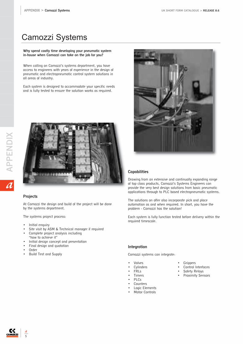
APPEN
DIX
APPENDIX > Camozzi Systems UK SHORT FORM CATALOGUE > RELEASE 8.6
a
a5
Why spend costly time developing your pneumatic systemin-house when Camozzi can take on the job for you?
When calling on Camozzi’s systems department, you haveaccess to engineers with years of experience in the design ofpneumatic and electropneumatic control system solutions inall areas of industry.
Each system is designed to accommodate your specific needsand is fully tested to ensure the solution works as required.
Capabilities
Drawing from an extensive and continually expanding rangeof top class products, Camozzi’s Systems Engineers canprovide the very best design solutions from basic pneumaticapplications through to PLC based electropneumatic systems.
The solutions on offer also incorporate pick and placeautomation as and when required. In short, you have theproblem - Camozzi has the solution!
Each system is fully function tested before delivery within therequired timescale.
• Valves• Cylinders• FRLs• Timers• PLCs• Counters• Logic Elements• Motor Controls
• Grippers• Control Interfaces• Safety Relays• Proximity Sensors
Integration
Camozzi systems can integrate:
Projects
At Camozzi the design and build of the project will be doneby the systems department.
The systems project process:
• Initial enquiry• Site visit by ASM & Technical manager if required• Complete project analysis including
“how to achieve it”• Initial design concept and presentation• Final design and quotation• Order• Build Test and Supply
Camozzi Systems

APPENDIX > Camozzi Assembly and Design UK SHORT FORM CATALOGUE > RELEASE 8.6
a
a 6
Camozzi Assembly and Design
Design
Camozzi offer a complete design package for ourcustomers
• Bespoke pneumatic products• Cabinets• Systems
Assembly
Camozzi have the capability to offer customers an assembly service,saving time and reducing costs.
By ordering one part number, a kit of parts can either be suppliedassembled or in a loose component form.

APPEN
DIX
APPENDIX > ATEX UK SHORT FORM CATALOGUE > RELEASE 8.6
a
a7
substances and an ignition source in a potentially explosive atmosphere.
An ignition source could be: • Electrical (electric arcs, induced current, heat generated by the Jouleeffect) • Mechanical (heat between surfacescaused by friction, sparks generatedby the collision of metallic bodies,electrostatic discharges, adiabaticcompression) • Chemical (exothermic reactions between materials) • Naked flames. The products which are subject to the approval are those which, during their normal use or because of a malfunction, present one or moreignition sources for the potentiallyexplosive atmospheres.
The producer has to guarantee that theproduct conforms with the declarationsand to the marking of the product.Moreover the product should always be accompanied by the relative instructions. The builder of the equipment and/or user should identifythe risk zone in which the products, to which directive 99/92/CE refers,
These are the main changes introduced by the new directive94/9/CE:• Also non-electric apparatus and devices, as pneumatic cylinders,are part of the Directive • The apparatus are assigned to different categories which are assignedto certain potentially explosive zones. • The products are identified with the CE mark Ex. • The instructions for use and the declarations of conformity should in order to be supplied with each sold product used in potentially explosive zones. • Products destined to be used inpotentially explosive zones, because of the presence of dust, are included in the directive like the products destined to be used in zones with the presence of dangerous gases. A potentially explosive atmospherecould be composed of gas, mist,steam or dust which can be created in manufacturing processes or in allthose areas in which there is a constant or randompresence of inflammable substances. An explosion can occur when there is an existing presence of inflammable
are used and purchase the product according to the use in the pre-determined zone paying attention to the specifications in the relativeinstructions.
In case a product is composed bytwo components with different markings, the component which isclassified in the lowest categorydefines the class to which the complete product belongs.
Example:solenoid suitable for Category 3 marked … Ex - II 3 EEx…
and valve suitable for Category 2 … Ex - II 2 EEx…The valve unit with solenoid can beused only in category 3 or zone 2/22.
Products Classified for the use in Potentially Esplosive Atmospheres (Directive Atex 94/9/CE)
Group I:
Apparatus for mines
CATEGOry M1Functioning in explosive atmosphere
CATEGOry M2Non-supplied equipment in explosive atmospheres
Group II:
Apparatus for industries above the ground
Product category GAS DuST
1 Zone 0 Zone 20
2 Zone 1 Zone 21
3 Zone 2 Zone 22
Zones, groups and categories
In the places and for the types of equipment subject to Directive 99/92/CE, the employer should execute
the classification of the zones regarding the danger of the creation of explosive atmospheres because of the presence of gas or dust.
The apparatus for the use in potentially explosive zones are divided in GrOuPS:
GrOuP I: apparatus used in mines
GrOuP II: apparatus used in installations above the ground.
As from the first of July 2003, all products which are commercialised in the European union and destined to be used in potentially explosive atmospheres, have to be approved according to the directive 94/9/CE, also known as ATEX.This new directive also refers to non-electric items, like pneumatic drives, which need to be approved.
» The European certificationfor products destined to be used in potentially explosive zones.
94/9/CE
ATEX

APPENDIX > ATEX UK SHORT FORM CATALOGUE > RELEASE 8.6
a
a 8
Classification in zones according to Directive 99/92/CE:
Category 1 Zone 0 - Area in which (permanently, for long periods or often) an explosive atmosphere is present, consisting of a mixture of
air and inflammables in the form of gas, vapour or mist.
Zone 20 - Area in which (permanently, for long periods or often) an explosive atmosphere is present in the form of a
dust/powder cloud which is combustible in the air.
Category 2 Zone 1 - Area in which, during normal activities, the formation of an explosive atmosphere is probable, consisting
of a mixture of air and inflammables in the form of gas, vapours or mist.
Zone 21 - Area in which occasionally during normal activities the formation of an explosive atmosphere is probable,
in the form of a dust/powder cloud which is combustible in the air.
Category 3 Zone 2 - Area in which, during normal activities, the formation of an explosive atmosphere, consisting of a mixture of air and
inflammables in the form of gas, vapour or mist is not probable and, whenever this should occur,
it is only of a short duration
Zone 22 - Area in which, during normal activities, the formation of an explosive atmosphere in the form of a combustible
dust/powder cloud is not probable and, whenever this should occur, it is only of a short duration.
ATEX certified Camozzi products
APPARATUS regarding ATEX - Group II
Group I: Temperature classes
Temperature =150 °C
or = 450 °C according to the level
of dust on the apparatus.
Group II: Temperature classes
Temp. classes for gas (G) Admissible surface temperatures
T1 450°C
T2 300°C
T3 200°C
T4 135°C
T5 100°C
T6 85°C
Example of Marking: II 2 GD c T100°C (T5) -20°C≤Ta≤60°C
II Group: Devices which are to be used in spaces exposed to risks of an explosive atmosphere, different from underground
spaces, mines, tunnels, etc., individuated according to the criteria in enclosure I of the Directive 94/9/CE (ATEX).
2 Category: Devices designed to function in compliance with the operational parameters determined by the manufacturer
and guarantee a high protection level.
GD Protected against gas (G) and explosive powders (D).
c Non-electrical constructions for potentially explosive atmospheres.
Protection through constructive security.
T 100°C Max. superf. temp. of 100 °C reg. potential hazards resulting from striking within the vicinity of hazardous powders.
T5 Max. superf. temp. of 100 °C regarding potential hazards which may result from striking within gassy environments.
Ta Environmental temperature: -20°C≤Ta≤60°C. Environmental temperature range (with dry air).
COMPONENTS regarding ATEX - Group II
Products Category Zone Gas/Dusti
Silencers 2 1/21 G/D
Quick release couplings 2 1/21 G/D
Manifolds 2 1/21 G/D
Sub-bases 2 1/21 G/D
Feet 2 1/21 G/D
Caps 2 1/21 G/D
Plates 2 1/21 G/D
» The order code number of the certified products is obtainedby adding "EX"Es. 358-015 standard solenoid valveEs. 358-015EX ATEX certified solenoid valve
Cylinders series Category Zone Gas/Dust
16* 2 DE-3 SE 1/21 DE -2/22 SE G/D
24* 2 DE-3 SE 1/21 DE-2/22SE G/D
25* 2 DE-3 SE 1/21 DE-2/22SE G/D
31 2 DE-3 SE 1/21DE-2/22SE G/D
31-32 Cylinders/Tandem/ 2 DE 1/21 DE G/Dmulti-position
40* 2 DE 1/21 DE G/D
41* 2 DE 1/21 DE G/D
60* 2 DE-3 SE 1/21DE-2/22 SE G/D
61* 2 DE-3 SE 1/21DE-2/22 SE G/D
62 3 DE 2/22 DE G/D
27 2 DE 1/21 DE G/D
QP-QPr 2 DE-3 SE 1/21DE-2/22 SE G/D
QN 3 SE 2/22 SE G/D
42 2 DE-3 SE 1/21DE-2/22 SE G/D
CST/CSV/CSh 3 2/22 G/D
Solenoids series Category Zone Gas/Dust
u70 3 2/22 G/D
h80 2 1/21 G/D
Valves series Category Zone Gas/Dust
9#* 2 1/21 G/D
k 3 2/22 G/D
P 3 2/22 G/D
W 3 2/22 G/D
A# 2 1/21 G/D
3# 2 1/21 G/D
4# 2 1/21 G/D
NAMur# 2 1/21 G/D
E (pneumatic) 2 1/21 G/D
E (electropneumatic) 3 2/22 G/D
y 3 2/22 G/D
2 2 1/21 G/D
FRL Groups Category Zone Gas/Dust
MC# 2 1/21 G/D
N 2 1/21 G/D
Pressure switches series Category Zone Gas/Dust
PM 1 0/20 G/D
* According ISO# Without solenoid
DA = Double-Acting cylindersSA = Single-Acting cylinders

APPEN
DIX
APPENDIX > Pneumatic Symbols UK SHORT FORM CATALOGUE > RELEASE 8.6
a
a9
Double acting cylinder, fixed cushions
Double acting cylinder, cushioned
Double acting cylinder, adjustable rear cushion
Double acting cylinder, adjustable front cushion
Double acting cylinder, through-rod, fixed cushions
Double acting cylinder, through-rod, adjustable front and rear cushion
Double acting cylinder, magnetic
Double acting cylinder, magnetic, fixed cushions
Double acting cylinder, magnetic, adjustable cushions in both directions
Double acting cylinder, magnetic, adjustable rear cushion
Double acting cylinder, magnetic, adjustable front cushion
Double acting cylinder, magnetic, through-rod, fixed cushions
Double acting cylinder, magnetic, through-rod, adjustable cushions in both directions
Double acting cylinder, magnetic, through-rod
Magnetic twin rod cylinders
Magnetic twin through-rod cylinders
Double acting rotary cylinder
Double acting rotary cylinder, magnetic
Single acting rotary cylinder
Magnetic tandem cylinder, two stages, fixed cushions
Magnetic tandem cylinder, three stages, fixed cushions
Magnetic tandem cylinder, four stages, fixed cushions
Magnetic multi-position cylinder, fixed cushions
Double acting rodless cylinder, magnetic
Single acting cylinder, front spring
CYLINDERS CYLINDERS
Single acting cylinder, front spring
Single acting cylinder, non cushioned
Single acting cylinder, through-rod
Single acting cylinder, through-rod, adjustable cushion
Single acting cylinder, magnetic
Single acting cylinder, front spring, adjustable rear cushion
Single acting cylinder, rear spring, magnetic
Single acting cylinder, magnetic, front spring
Single acting cylinder, through-rod
Single acting cylinder, through-rod, adjustable rear cushion
hydrocheck, regulated rod thrust
hydrocheck, regulated rod return
hydrocheck, regulated rod thrust with stop valve
hydrocheck, regulated rod return with stop valve
hydrocheck, regulated rod thrust with skip valve
hydrocheck, regulated rod return with skip valve
hydrocheck, regulated rod thrust with skip and stop valve
hydrocheck, regulated rod return with skip and stop valve
Double acting magnetic grippers
rod lock device
SOLENOID VALVES
Directly operated solenoid valve, 2/2 NC
Directly operated solenoid valve, 2/2 NO
Directly operated solenoid valve, 3/2 NCs
Directly operated solenoid valve, 3/2 NC, monostable, with manual override
CD01
CD02
CD03
CD04
CD05
CD06
CD07
CD08
CD09
CD10
CD11
CD12
CD13
CD14
CD15
CD16
CD17
CD18
CD19
CD2T
CD3T
CD4T
CDPP
CDSS
CS01
CS03
CS04
CS05
CS06
CS07
CS08
CS09
CS10
CS11
HI01
HI02
HI03
HI04
HI05
HI06
HI07
HI08
PNZ1
RDLK
CS02
EV04
EV01
EV02
EV03
Pneumatic Symbols
Symbol TypeSymbol Type

APPENDIX > Pneumatic SymbolsUK SHORT FORM CATALOGUE > RELEASE 8.6
a
a 10
Symbol TypeSymbol Type
SOLENOID VALVES SOLENOID VALVES
Directly operated solenoid valve, 3/2 NO
Directly operated solenoid valve, 3/2 NO, monostable, with manual override
Solenoid valve, 3/2 NC with quick exhaust
Directly operated solenoid valve, 3/2 NC, bistable, with manual override
Directly operated solenoid valve, 3/2 NO, bistable, with manual override
Solenoid valve, 3/2 NC, monostable, with bistable manual override
Solenoid valve, 3/2, monostable, solenoid pilot with separate air supply and bistable manual override
Solenoid valve, 3/2 NO, monostable, with bistable manual override
Solenoid valve, 3/2, monostable, solenoid pilot with separate air supply and bistable manual override
Solenoid valve, 3/2, bistable, with manual override bistabile
Solenoid valve, 3/2, bistable, solenoid pilot with separate air supply and bistable manual override
Solenoid valve, 3/2 NC, monostable, (pneumatic spring) and bistable manual override
Solenoid valve, 3/2 NO, monostable, (pneumatic spring) and bistable manual override
Solenoid valve, 5/2, monostable, with bistable manual override
Solenoid valve, 5/2, monostable, solenoid pilot with separate air supply and bistable manual override
Solenoid valve, 5/2, monostable, (pneumatic spring) and manual override
Solenoid valve, 5/2, monostable, (pneumatic spring) and bistable manual override
Solenoid valve, 5/2, monostable, solenoid pilotwith separate air supply, pneumatic spring and bistable manual override
Solenoid valve, 5/2, bistable, with bistable manual override
Solenoid valve, 5/2, bistable, with manual override
Solenoid valve, 5/2, bistable, solenoid pilot with separate air supply and bistable manual override
Solenoid valve, 5/2, bistable, solenoid pilot with separate air supply and bistable manual override
Solenoid valve, 5/3 CC, with manual override
Solenoid valve, 5/3 CC, with bistable manual override
Solenoid valve, 5/3, solenoid pilot with separate air supply and bistable manual override
Solenoid valve, 5/3, solenoid pilot with separate air supply and bistable manual override
Solenoid valve, 5/3 CO, with manual override
Solenoid valve, 5/3 CO, with bistable manual override
Solenoid valve, 5/3 CO, solenoid pilot with separate air supply and bistable manual override
Solenoid valve, 5/3 CO, solenoid pilot with separate air supply and bistable manual override
Solenoid valve, 5/3 CP, with manual override
Solenoid valve, 5/3 CP, with bistable manual override
Solenoid valve, 5/3 CP, solenoid pilot with separate air supply and bistable manual override
Solenoid valve, 5/3 CP, solenoid pilot with separate air supply and bistable manual override
Double solenoid valve, 3/2 NC, monostable, with bistable manual override
Double solenoid valve, 3/2, monostable, solenoid pilot with separate air supply and bistable manual override
Double solenoid valve, 3/2 NO, monostable, with bistable manual override
Double solenoid valve, 3/2, monostable, solenoid pilot with separate air supply and bistable manual override
Double solenoid valve, 3/2 NC, NO, monostable, with bistable manual override
Double solenoid valve, 3/2, monostable, solenoid pilot with separate air supply and bistable manual override
Directly operated solenoid valve, 3/2, possible universal use, reversed printed ports1 and 2 on the body
Indirectly operated solenoid valve, 2/2 NO
Directly operated solenoid valve, 2/2 NC, with linked diaphragm
Indirectly operated solenoid valve, 2/2 NC
PNEUMATICALLY OPERATED VALVES
Pneumatically operated valve, 3/2, monostable, mechanical spring
Pneumatically operated valve, 3/2, bistable
Pneumatically operated valve, 3/2, preferential
Pneumatically operated valve, 5/2, monostable, mechanical spring
Pneumatically operated valve, 5/2, preferential
Pneumatically operated valve, 5/2, bistable
EV05
EV06
EV07
EV08
EV09
EV10
EV11
EV12
EV13
EV14
EV15
EV16
EV17
EV18
EV19
EV20
EV21
EV22
EV23
EV24
EV25
EV26
EV27
EV48
EV47
EV46
EV43
EV42
EV45
EV44
EV41
EV40
EV39
EV38
EV37
EV36
EV35
EV29
EV30
EV31
EV32
EV33
EV34
EV28
VP01
VP02
VP03
VP04
VP05
VP06

APPEN
DIX
APPENDIX > Pneumatic Symbols UK SHORT FORM CATALOGUE > RELEASE 8.6
a
a11
AND1
AND2
ORO1VM21
VN01
VN02
VN03
VN04
VN05
VN06
VN07
VN08
VN09
VN10
VN11
VN12
VN13
VN14
VN15
VN16
VN17
VN18
VN19
VN20
VN21
VN22
VN23
VN24
VN25
Symbol TypeSymbol Type
PNEUMATICALLY OPERATED VALVES MANUALLY OPERATED VALVES
Pneumatically operated valve, 5/2, monostable, pneumatic spring
Pneumatically operated valve, 5/3 CC
Pneumatically operated valve, 5/3 CO
Pneumatically operated valve, 5/3 CP
Pneumatically operated double valve, 3/2, monostable
Pneumatically operated double valve, 3/2, monostable
Pneumatically operated double valve, 3/2, monostable
MEChANICALLY OPERATED VALVES
Mechanically operated valve, plunger actuation, 3/2 NC, monostable, mechanical spring
Mechanically operated valve, plunger actuation, 3/2, monostable, mechanical spring
Mechanically operated valve, plunger actuation, 3/2 NO, monostable, mechanical spring
Mechanically operated valve, lever/roller actuation, 3/2 NC, monostable,mechanical spring
Mechanically operated valve, lever/roller actuation, 3/2, monostable, mechanical spring
Mechanically operated valve, lever/roller actuation, 3/2 NO, monostabile,mechanical spring
Mechanically operated valve, unidirectional lever actuation, 3/2 NC, monostable, mechanical spring
Mechanically operated valve, unidirectional lever actuation, 3/2 monostable, mechanical spring
Mechanically operated valve, plunger actuation, 5/2, monostable, mechanical spring
Mechanically operated valve, plunger actuation, 5/2, monostable, mechanical spring
Mechanically operated valve, lever/roller actuation, 5/2, monostable, mechanical spring
Mechanically operated valve, lever/roller actuation, 5/2, monostable, mechanical spring
Mechanically operated valve, unidirectional lever actuation, 5/2, monostable, mechanical spring
Mechanically operated sensor valve, 3/2 NO, monostable, mechanical spring
Mechanically operated sensor valve, 3/2 NC, monostable, mechanical spring
Mechanically operated sensor valve, plunger actuation, 5/2, monostable, mechanical spring
Mechanically operated sensor valve, plunger actuation, 5/2, bistable
Valvola a comando meccanico frontale sensibile 5/2, bistabile
Mechanically operated sensor valve, lever/roller actuation, 5/2, monostable, mechanical spring
Mechanically operated sensor valve, lever/roller actuation, 5/2, bistable
Mechanically operated valve, unidirectional lever actuation, 3/2 NO, monostable, mechanical spring
Manually operated valve, 3/2, bistable
Manually operated valve, 3/2, bistable, lockable in two positions
Manually operated valve, 3/2, bistable
Manually operated valve, 3/2 NC, monostable, mechanical spring
Manually operated valve, 3/2 NO, monostable, mechanical spring
Manually operated valve, 3/2, monostable, mechanical spring
Manually operated lever valve, 3/2, bistable
Manually operated lever valve, 3/2, bistable
Manually operated lever valve, 3/2 NC, monostable, mechanical spring
Manually operated lever valve, 3/2, bistable
Manually operated lever valve, 3/2, monostable, mechanical spring
Pedal operated valve, 3/2 NC, monostable, mechanical spring
Manually operated valve, 5/2, bistable
Manually operated valve, 5/2, monostable, mechanical spring
Manually operated lever valve, 5/2, bistable
Manually operated lever valve, 5/2, bistable
Manually operated lever valve, 5/2, monostable, mechanical spring
Pedal operated valve, 5/2, bistable
Pedal operated valve, 5/2, monostable bistable
Manually operated lever valve, 5/3 CC, stable
Manually operated lever valve, 5/3 CC, monostable
Manually operated lever valve, 5/3 CO, stable
Manually operated lever valve, 5/3 CO, stable
Manually operated lever valve, 5/3 CO, monostable
Manually operated lever valve, Joystik
PNEUMATIC LOGIC VALVES
"AND" pneumatic symbol
"AND" logical symbol
"Or" pneumatical symbol and circuit selector
VP07
VP08
VP09
VP10
VP11
VP12
VP13
VM01
VM02
VM03
VM04
VM05
VM06
VM07
VM08
VM09
VM10
VM11
VM12
VM13
VM14
VM15
VM18
VM19
VM20
VM17
VM16

APPENDIX > Pneumatic SymbolsUK SHORT FORM CATALOGUE > RELEASE 8.6
a
a 12
FT01
FT02
FT03
FA01
FA02
FA03
FC01
PR01
PR02
PR03
PR04
PR05
PR06
LU0
FR01
FR02
FR04
FR05
FR10
FR11
FR18
FR19
VN02
AVP1
BL01
BL02
FR03
ORO2
YES1
YES2
NOT1
NOT2
MEM1
MEM2
2LB1
2LB2
VSC1
VBU1
VB01
PMNA
PMNC
PMSC
TRP1
RFU1
RFO1
RP01
RP02
RP03
VNR1
SIL1
RSW1
SEG1
CAP1
Symbol TypeSymbol Type
"Or" logical symbol
"yES" pneumatic symbol
"yES" logical symbol
"NOT" pneumatic symbol
"NOT" logical symbol
"MEMOry" pneumatic symbol
"MEMOry" logical symbol
Signal amplifier, 3/2 NC, mechanical spring return
Jet interruption sender sensor
Jet interruption receiver sensor
AUTOMATIC VALVES
"Or" pneumatical symbol and circuit selector
Quick exhaust valves
unidirectional blocking valves
bidirectional blocking valves
Non return valves
FLOw CONTROL VALVES
unidirectional flow control valve
bidirectional flow control valve
unidirectional flow control valve
unidirectional flow control valve
bidirectional flow control valve
PRESSURE SwITChES AND VACUUM SwITChES
Pressure switch, normally open
Pressure switch, normally closed
Pressure swith with exchange contacts
Electro-pneumatic transducer
Pressure indicator
Capacity
SILENCIER
Silencier
Silenced exhaust controller
Filter without drain
Filter with manual drain
Filter with automatic drain
Coalescing filter without drain
Coalescing filter with manual drain
Coalescing filter with automatic drain
Absorption function without cup hole
regulator without relieving
regulator with relieving
regulator with relieving and by-pass valve
regulator without relieving and with by-pass valve
regulator without relieving and with pressure gauge
regulator with relieving and with pressure gauge
Lubricator
Filter-regulator with relieving and manual drain
Filter-regulator with relieving and without drain
Filter-regulator with relieving, manual drain and pressure gauge
Filter-regulator with relieving, without drain and with pressure gauge
Filter-regulator with relieving, automatic drain and pressure gauge
Filter-regulator with manual drain, without relieving and with pressure gauge
Filter-regulator with manual drain and without relieving
Filter-regulator with relieving and automatic drain
Manifold pressure regulator
Lockable isolation valve
Soft start valve
Take-off block
Take-off block with VNr
PNEUMATIC LOGIC VALVES FRL
AMP1
ORO1

APPEN
DIX
APPENDIX > Technical information about products UK SHORT FORM CATALOGUE > RELEASE 8.6
a
a13
Spring Loads Cylinders
stroke mm
Series QP
stroke mm
Series QP
stroke mm
stroke mm
stroke mm
stroke mm
stroke mm
Series 16-24 Series 31-32
Series 31-32 Series 60-61-42-90
stroke mm
Series 14 - stroke 5 mm Series 14 - stroke 10 and 15 mm
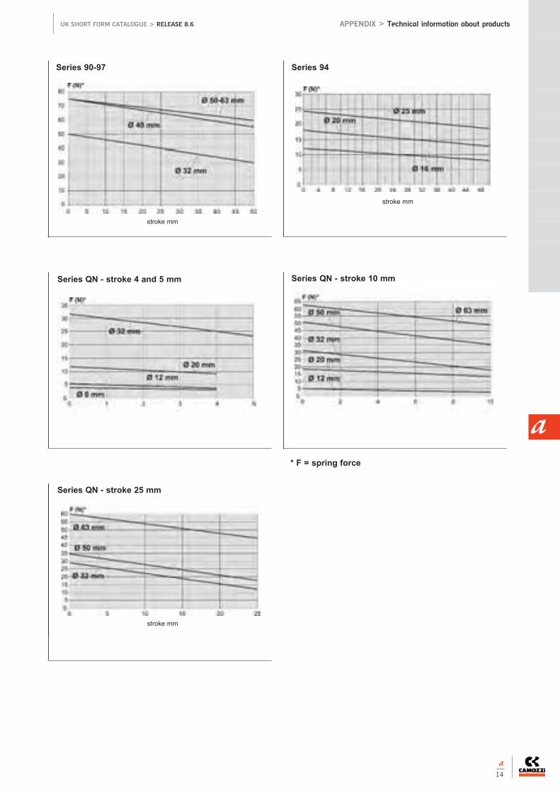
APPENDIX > Technical information about products UK SHORT FORM CATALOGUE > RELEASE 8.6
a
a 14
stroke mm
stroke mmstroke mm
stroke mm
Series QN - stroke 10 mm
Series QN - stroke 25 mm
Series 94
Series QN - stroke 4 and 5 mm
* F = spring force
stroke mm
Series 90-97

APPEN
DIX
APPENDIX > Technical information about products UK SHORT FORM CATALOGUE > RELEASE 8.6
a
a15
Valves and solenoid valves
Maximum speeds obtainable combining
a certain flow regulator (mm/sec) with a cylinder
Flow survey instruments.
The flow rate indicated in the catalogue is
obtained with
P1 = 6 bar e P2 = 5 bar.
Flow and Speed Cylinders
Flow measurer
Flow regulatorElement being testedPressure regulator
Tap
Cylinders diameter (mm)
MOD. 32 40 50 63 80 100 125
GSCu-1/8”; GSVu-1/8”; GMCu-1/8”; GSCu-1/8” 1000 986 629 395 246 158 100
GSCu-1/4”; GSVu-1/4”; GMCu-1/4”; GSCu-1/4” - 1000 911 573 357 229 145
rFu 452 M5 204 - - - - - -
rFu 482-1/8” 227 145 93 58 36 - -
rFu 483-1/8” 520 333 212 133 83 53 -
rFu 444-1/4” - 739 471 296 185 118 75
rFu 446-1/4” - - 847 532 332 213 135
SCu M5 - SVu M5 154 - - - - - -
SCu-1/4”; SVu-1/4”; MCu-1/4”; MVu-1/4” - 1000 660 415 259 166 105
SCu-1/8”; SVu-1/8”; MCu-1/8”; MVu-1/8” 604 387 247 155 97 62 -
SCu-3/8”; MCu-3/8” - - - 622 388 249 158
SCu-1/2”; MCu-1/2” - - - - 1000 869 -
To obtain the above indicated speeds, the connected tubing should have a certain diameter
and not exceed, if indicated, the max. lenght (mm)
Tube diameter and max length (m)
4/2 6/4 8/6 10/8 12/10
GSCu-1/8”; GSVu-1/8”; GMCu-1/8”; GSCu-1/8” - 0.4 8 25 -
GSCu-1/4”; GSVu-1/4”; GMCu-1/4”; GSCu-1/4” - - 4.5 18 24
rFu 452 M5 3.5 25 - - -
rFu 482-1/8” 3 25 - - -
rFu 483-1/8” 0.25 10 - - -
rFu 444-1/4” - 2 17 - -
rFu 446-1/4” - - 5 20 -
SCu M5 - SVu M5 5 - - - -
SCu-1/4”; SVu-1/4”; MCu-1/4”; MVu-1/4” - 0.4 8 25 -
SCu-1/8”; SVu-1/8”; MCu-1/8”; MVu-1/8” - 7 - - -
SCu-3/8”; MCu-3/8” - - 3.5 - -
SCu-1/2”; MCu-1/2” - - - 0.25 3.5

APPENDIX > Technical information about products UK SHORT FORM CATALOGUE > RELEASE 8.6
a
a 16
Air flow required by the valve (6 bar) to obtain the above indicated speeds (Nl/min)
Cylinders diameter (mm)
32 40 50 63 80 100 125
GSCu-1/8”; GSVu-1/8”; GMCu-1/8”; GSCu-1/8” 336 217 517 517 517 517 517
GSCu-1/4”; GSVu-1/4”; GMCu-1/4”; GSCu-1/4” - 525 750 750 750 750 750
rFu 452 M5 69 - - - - - -
rFu 482-1/8” 76 76 76 76 76 - -
rFu 483-1/8” 175 175 175 175 175 175 -
rFu 444-1/4” - 388 388 388 388 388 388
rFu 446-1/4” - - 697 697 697 697 697
SCu M5 - SVu M5 52 - - - - - -
SCu-1/4”; SVu-1/4”; MCu-1/4”; MVu-1/4” - 525 543 543 543 543 543
SCu-1/8”; SVu-1/8”; MCu-1/8”; MVu-1/8” 203 203 203 203 203 203 -
SCu-3/8”; MCu-3/8” - - - 815 815 815 815
SCu-1/2”; MCu-1/2” - - - - 2100 2846 -

APPEN
DIX
APPENDIX > Technical information about products UK SHORT FORM CATALOGUE > RELEASE 8.6
a
a17
Output Forces Double-Acting Cylinders
SERIES >
SERIES >
Ø Thrust Pressure
side MPa (bar) MPa (bar) MPa (bar) MPa (bar) MPa (bar) MPa (bar) MPa (bar) MPa (bar) MPa (bar) MPa (bar)
mm cm2 0,10 (1) 0,20 (2) 0,30 (3) 0,40 (4) 0,50 (5) 0,60 (6) 0,70 (7) 0,80 (8) 0,90 (9) 1 (10)
10 1,58 14,22 28,44 42,66 56,88 71,1 85,32 99,54 113,76 127,98 142,2
16 4,02 35,48 71 106,4 142 177,4 213 248,4 283,8 319,4 354,8
20 6,28 55,44 110,8 166,4 221,8 277,2 332,6 388,2 443,6 499 554,4
25 9,82 86,64 173,2 260 346,6 433,2 519,8 606,4 693 779,8 866,4
32 16,08 141,94 283,8 425,8 567,8 709,8 851,6 993,6 1135,6 1277,4 1419,4
SERIES > QX
Ø Thrust Ø Traction Pressure
side rod side MPa (bar) MPa (bar) MPa (bar) MPa (bar) MPa (bar) MPa (bar) MPa (bar) MPa (bar) MPa (bar) MPa (bar)
mm cm2 0,10 (1) 0,20 (2) 0,30 (3) 0,40 (4) 0,50 (5) 0,60 (6) 0,70 (7) 0,80 (8) 0,90 (9) 1 (10)
10 1,58 6 1,0148 9,1332 18,2664 27,3996 36,5328 45,666 54,7992 63,9324 73,0656 82,1988 91,332
16 4,02 16 3,02 26,62 53,2 79,8 106,4 133 159,6 186,2 213 239,6 266,2
20 6,28 20 4,72 41,58 83,2 124,8 166,4 208 249,6 291 332,6 374,2 415,8
25 9,82 24 7,56 66,68 133,4 200 266,6 333,4 400 466,8 533,4 600 666,8
32 16,08 32 12,06 106,46 213 319,4 425,8 532,2 638,8 745,2 851,6 958,2 1064,6
SERIES > QX
16 24 25 40 41 42 60 61 62 90 94 95 97
Thrust side Values in Newton
Traction side Values in Newton
16 24 25 27 31 32 QP QN QCT QCb QCTb QCTF 40 41 42 50 52 60 61 62 90 94 95 97
Ø Thrust Ø Traction Pressure
side rod side MPa (bar) MPa (bar) MPa (bar) MPa (bar) MPa (bar) MPa (bar) MPa (bar) MPa (bar) MPa (bar) MPa (bar)
mm cm2 mm cm2 0,10 (1) 0,20 (2) 0,30 (3) 0,40 (4) 0,50 (5) 0,60 (6) 0,70 (7) 0,80 (8) 0,90 (9) 1 (10)
8 0,50 4 0,38 3,33 6,7 10,0 13,3 16,6 20,0 23,3 26,6 29,9 33,3
10 0,79 4 0,66 5,82 11,6 17,5 23,3 29,1 34,9 40,8 46,6 52,4 58,2
12 1,13 6 0,85 7,49 15,0 22,5 29,9 37,4 44,9 52,4 59,9 67,4 74,9
16 2,01 6 1,73 15,25 30,5 45,7 61,0 76,2 91,5 106,7 122,0 137,2 152,5
20 3,14 8 2,64 23,29 46,6 69,9 93,1 116,4 139,7 163,0 186,3 209,6 232,9
25 4,91 10 4,12 36,39 72,8 109,2 145,5 181,9 218,3 254,7 291,1 327,5 363,9
32 8,04 12 6,91 60,99 122,0 183,0 244,0 305,0 365,9 426,9 487,9 548,9 609,9
40 12,56 16 10,55 93,15 186,3 279,4 372,6 465,7 558,9 652,0 745,2 838,3 931,5
50 19,63 20 16,49 145,55 291,1 436,6 582,2 727,7 873,3 1018,8 1164,4 1309,9 1455,5
63 31,16 20 28,02 247,36 494,7 742,1 989,4 1236,8 1484,2 1731,5 1978,9 2226,2 2473,6
80 50,24 25 45,33 400,25 800,5 1200,8 1601,0 2001,3 2401,5 2801,8 3202,0 3602,3 4002,5
100 78,50 25 73,59 649,76 1299,5 1949,3 2599,0 3248,8 3898,6 4548,3 5198,1 5847,8 6497,6
125 122,66 32 114,62 1011,96 2023,9 3035,9 4047,8 5059,8 6071,8 7083,7 8095,7 9107,6 10119,6
160 200,96 40 188,40 1663,38 3326,8 4990,2 6653,5 8316,9 9980,3 11643,7 13307,1 14970,5 16633,8
200 314,00 40 301,44 2661,41 5322,8 7984,2 10645,7 13307,1 15968,5 18629,9 21291,3 23952,7 26614,1
250 490,62 50 471,00 4158,46 8316,9 12475,4 16633,8 20792,3 24950,8 29109,2 33267,7 37426,1 41584,6
320 803,84 63 772,68 6822,02 13644,0 20466,1 27288,1 34110,1 40932,1 47754,1 54576,2 61398,2 68220,2
Ø Thrust Pressure
side MPa (bar) MPa (bar) MPa (bar) MPa (bar) MPa (bar) MPa (bar) MPa (bar) MPa (bar) MPa (bar) MPa (bar)
mm cm2 0,10 (1) 0,20 (2) 0,30 (3) 0,40 (4) 0,50 (5) 0,60 (6) 0,70 (7) 0,80 (8) 0,90 (9) 1 (10)
8 0,50 4,44 8,9 13,3 17,7 22,2 26,6 31,0 35,5 39,9 44,4
10 0,79 6,93 13,9 20,8 27,7 34,7 41,6 48,5 55,4 62,4 69,3
12 1,13 9,98 20,0 29,9 39,9 49,9 59,9 69,9 79,8 89,8 99,8
16 2,01 17,74 35,5 53,2 71,0 88,7 106,5 124,2 141,9 159,7 177,4
20 3,14 27,72 55,4 83,2 110,9 138,6 166,3 194,1 221,8 249,5 277,2
25 4,91 43,32 86,6 130,0 173,3 216,6 259,9 303,2 346,5 389,9 433,2
32 8,04 70,97 141,9 212,9 283,9 354,9 425,8 496,8 567,8 638,7 709,7
40 12,56 110,89 221,8 332,7 443,6 554,5 665,4 776,2 887,1 998,0 1108,9
50 19,63 173,27 346,5 519,8 693,1 866,3 1039,6 1212,9 1386,2 1559,4 1732,7
63 31,16 275,08 550,2 825,2 1100,3 1375,4 1650,5 1925,6 2200,7 2475,7 2750,8
80 50,24 443,57 887,1 1330,7 1774,3 2217,8 2661,4 3105,0 3548,6 3992,1 4435,7
100 78,50 693,08 1386,2 2079,2 2772,3 3465,4 4158,5 4851,5 5544,6 6237,7 6930,8
125 122,66 1082,93 2165,9 3248,8 4331,7 5414,7 6497,6 7580,5 8663,5 9746,4 10829,3
160 200,96 1774,28 3548,6 5322,8 7097,1 8871,4 10645,7 12419,9 14194,2 15968,5 17742,8
200 314,00 2772,31 5544,6 8316,9 11089,2 13861,5 16633,8 19406,1 22178,4 24950,8 27723,1
250 490,62 4331,73 8663,5 12995,2 17326,9 21658,6 25990,4 30322,1 34653,8 38985,6 43317,3
320 803,84 7097,10 14194,2 21291,3 28388,4 35485,5 42582,6 49679,7 56776,8 63873,9 70971,0

APPENDIX > Technical information about products UK SHORT FORM CATALOGUE > RELEASE 8.6
a
a 18
31SERIES >
Ø Thrust Ø Traction Pressure
side rod side MPa (bar) MPa (bar) MPa (bar) MPa (bar) MPa (bar) MPa (bar) MPa (bar) MPa (bar) MPa (bar) MPa (bar)
mm cm2 mm cm2 0,10 (1) 0,20 (2) 0,30 (3) 0,40 (4) 0,50 (5) 0,60 (6) 0,70 (7) 0,80 (8) 0,90 (9) 1 (10)
12 1,13 6 0,85 7,49 15,0 22,5 29,9 37,4 44,9 52,4 59,9 67,4 74,9
16 2,01 8 1,51 13,31 26,6 39,9 53,2 66,5 79,8 93,1 106,5 119,8 133,1
20 3,14 10 2,36 20,79 41,6 62,4 83,2 104,0 124,8 145,5 166,3 187,1 207,9
25 4,91 10 4,12 36,39 72,8 109,2 145,5 181,9 218,3 254,7 291,1 327,5 363,9
32 8,04 12 6,91 60,99 122,0 183,0 244,0 305,0 365,9 426,9 487,9 548,9 609,9
40 12,56 16 10,55 93,15 186,3 279,4 372,6 465,7 558,9 652,0 745,2 838,3 931,5
50 19,63 16 17,62 155,53 311,1 466,6 622,1 777,6 933,2 1088,7 1244,2 1399,7 1555,3
63 31,16 20 28,02 247,36 494,7 742,1 989,4 1236,8 1484,2 1731,5 1978,9 2226,2 2473,6
80 50,24 25 45,33 400,25 800,5 1200,8 1601,0 2001,3 2401,5 2801,8 3202,0 3602,3 4002,5
100 78,50 25 73,59 649,76 1299,5 1949,3 2599,0 3248,8 3898,6 4548,3 5198,1 5847,8 6497,6
Ø Thrust Ø Traction Pressure
side rod side MPa (bar) MPa (bar) MPa (bar) MPa (bar) MPa (bar) MPa (bar) MPa (bar) MPa (bar) MPa (bar) MPa (bar)
mm cm2 mm cm2 0,10 (1) 0,20 (2) 0,30 (3) 0,40 (4) 0,50 (5) 0,60 (6) 0,70 (7) 0,80 (8) 0,90 (9) 1 (10)
12 1,13 6 0,85 7,49 15,0 22,5 29,9 37,4 44,9 52,4 59,9 67,4 74,9
16 2,01 8 1,51 13,31 26,6 39,9 53,2 66,5 79,8 93,1 106,5 119,8 133,1
20 3,14 10 2,36 20,79 41,6 62,4 83,2 104,0 124,8 145,5 166,3 187,1 207,9
25 4,91 10 4,12 36,39 72,8 109,2 145,5 181,9 218,3 254,7 291,1 327,5 363,9
32 8,04 12 6,91 60,99 122,0 183,0 244,0 305,0 365,9 426,9 487,9 548,9 609,9
40 12,56 12 11,43 100,91 201,8 302,7 403,6 504,6 605,5 706,4 807,3 908,2 1009,1
50 19,63 16 17,62 155,53 311,1 466,6 622,1 777,6 933,2 1088,7 1244,2 1399,7 1555,3
63 31,16 16 29,15 257,34 514,7 772,0 1029,4 1286,7 1544,0 1801,4 2058,7 2316,1 2573,4
80 50,24 20 47,10 415,85 831,7 1247,5 1663,4 2079,2 2495,1 2910,9 3326,8 3742,6 4158,5
100 78,50 25 73,59 649,76 1299,5 1949,3 2599,0 3248,8 3898,6 4548,3 5198,1 5847,8 6497,6
QPSERIES >
27SERIES >
Ø Thrust Ø Traction Pressure
side rod side MPa (bar) MPa (bar) MPa (bar) MPa (bar) MPa (bar) MPa (bar) MPa (bar) MPa (bar) MPa (bar) MPa (bar)
mm cm2 mm cm2 0,10 (1) 0,20 (2) 0,30 (3) 0,40 (4) 0,50 (5) 0,60 (6) 0,70 (7) 0,80 (8) 0,90 (9) 1 (10)
20 3,14 8 2,64 23,29 46,6 69,9 93,1 116,4 139,7 163,0 186,3 209,6 232,9
25 4,91 10 4,12 36,39 72,8 109,2 145,5 181,9 218,3 254,7 291,1 327,5 363,9
32 8,04 12 6,91 60,99 122,0 183,0 244,0 305,0 365,9 426,9 487,9 548,9 609,9
40 12,56 16 10,55 93,15 186,3 279,4 372,6 465,7 558,9 652,0 745,2 838,3 931,5
50 19,63 16 17,62 155,53 311,1 466,6 622,1 777,6 933,2 1088,7 1244,2 1399,7 1555,3
63 31,16 20 28,02 247,36 494,7 742,1 989,4 1236,8 1484,2 1731,5 1978,9 2226,2 2473,6
SERIES >
Ø Thrust Ø Traction Pressure
side rod side MPa (bar) MPa (bar) MPa (bar) MPa (bar) MPa (bar) MPa (bar) MPa (bar) MPa (bar) MPa (bar) MPa (bar)
mm cm2 mm cm2 0,10 (1) 0,20 (2) 0,30 (3) 0,40 (4) 0,50 (5) 0,60 (6) 0,70 (7) 0,80 (8) 0,90 (9) 1 (10)
20 3,14 10 2,36 20,79 41,6 62,4 83,2 104,0 124,8 145,5 166,3 187,1 207,9
25 4,91 12 3,78 33,34 66,7 100,0 133,3 166,7 200,0 233,4 266,7 300,0 333,4
32 8,04 16 6,03 53,23 106,5 159,7 212,9 266,1 319,4 372,6 425,8 479,1 532,3
40 12,56 16 10,55 93,15 186,3 279,4 372,6 465,7 558,9 652,0 745,2 838,3 931,5
50 19,63 20 16,49 145,55 291,1 436,6 582,2 727,7 873,3 1018,8 1164,4 1309,9 1455,5
63 31,16 20 28,02 247,36 494,7 742,1 989,4 1236,8 1484,2 1731,5 1978,9 2226,2 2473,6
QCT QCb QCTF QCbF
32
Traction side Values in Newton

APPEN
DIX
APPENDIX > Technical information about products UK SHORT FORM CATALOGUE > RELEASE 8.6
a
a19
Table Showing Air Consumption of Double-Acting Cylinders
SERIES >
Ø Thrust Ø Traction Pressure
side rod side MPa (bar) MPa (bar) MPa (bar) MPa (bar) MPa (bar) MPa (bar) MPa (bar) MPa (bar) MPa (bar) MPa (bar)
mm cm2 mm cm2 0,10 (1) 0,20 (2) 0,30 (3) 0,40 (4) 0,50 (5) 0,60 (6) 0,70 (7) 0,80 (8) 0,90 (9) 1 (10)
8 0,50 4 0,38 0,001 0,001 0,002 0,002 0,002 0,003 0,003 0,003 0,004 0,004
10 0,79 4 0,66 0,001 0,002 0,003 0,003 0,004 0,005 0,005 0,006 0,007 0,007
12 1,13 6 0,85 0,002 0,003 0,003 0,004 0,005 0,006 0,007 0,008 0,008 0,009
16 2,01 6 1,73 0,003 0,005 0,007 0,009 0,010 0,012 0,014 0,016 0,017 0,019
20 3,14 8 2,64 0,005 0,008 0,011 0,013 0,016 0,018 0,021 0,024 0,026 0,029
25 4,91 10 4,12 0,008 0,012 0,016 0,021 0,025 0,029 0,033 0,037 0,041 0,045
32 8,04 12 6,91 0,014 0,021 0,028 0,035 0,041 0,048 0,055 0,062 0,069 0,076
40 12,56 16 10,55 0,021 0,032 0,042 0,053 0,063 0,074 0,084 0,095 0,106 0,116
50 19,63 20 16,49 0,033 0,049 0,066 0,082 0,099 0,115 0,132 0,148 0,165 0,181
63 31,16 20 28,02 0,056 0,084 0,112 0,140 0,168 0,196 0,224 0,252 0,280 0,308
80 50,24 25 45,33 0,091 0,136 0,181 0,227 0,272 0,317 0,363 0,408 0,453 0,499
100 78,50 25 73,59 0,147 0,221 0,294 0,368 0,442 0,515 0,589 0,662 0,736 0,810
125 122,66 32 114,62 0,229 0,344 0,458 0,573 0,688 0,802 0,917 1,032 1,146 1,261
160 200,96 40 188,40 0,377 0,565 0,754 0,942 1,130 1,319 1,507 1,696 1,884 2,072
200 314,00 40 301,44 0,603 0,904 1,206 1,507 1,809 2,110 2,412 2,713 3,014 3,316
250 490,63 50 471,00 0.942 1,413 1,884 2,355 2,826 3,297 3,768 4,239 4,710 5,181
320 803,84 63 772,68 1,545 2,318 3,091 3,863 4,636 5,409 6,181 6,954 7,727 8,500
SERIES >
Ø Thrust Pressure
side MPa (bar) MPa (bar) MPa (bar) MPa (bar) MPa (bar) MPa (bar) MPa (bar) MPa (bar) MPa (bar) MPa (bar)
mm cm2 0,10 (1) 0,20 (2) 0,30 (3) 0,40 (4) 0,50 (5) 0,60 (6) 0,70 (7) 0,80 (8) 0,90 (9) 1 (10)
8 0,50 0,001 0,002 0,002 0,003 0,003 0,004 0,004 0,005 0,005 0,006
10 0,79 0,002 0,002 0,003 0,004 0,005 0,005 0,006 0,007 0,008 0,009
12 1,13 0,002 0,003 0,005 0,006 0,007 0,008 0,009 0,010 0,011 0,012
16 2,01 0,004 0,006 0,008 0,010 0,012 0,014 0,016 0,018 0,020 0,022
20 3,14 0,006 0,009 0,013 0,016 0,019 0,022 0,025 0,028 0,031 0,035
25 4,91 0,010 0,015 0,020 0,025 0,029 0,034 0,039 0,044 0,049 0,054
32 8,04 0,016 0,024 0,032 0,040 0,048 0,056 0,064 0,072 0,080 0,088
40 12,56 0,025 0,038 0,050 0,063 0,075 0,088 0,100 0,113 0,126 0,138
50 19,63 0,039 0,059 0,079 0,098 0,118 0,137 0,157 0,177 0,196 0,216
63 31,16 0,062 0,093 0,125 0,156 0,187 0,218 0,249 0,280 0,312 0,343
80 50,24 0,100 0,151 0,201 0,251 0,301 0,352 0,402 0,452 0,502 0,553
100 78,50 0,157 0,236 0,314 0,393 0,471 0,550 0,628 0,707 0,785 0,864
125 122,66 0,245 0,368 0,491 0,613 0,736 0,859 0,981 1,104 1,227 1,349
160 200,96 0,402 0,603 0,804 1,005 1,206 1,407 1,608 1,809 2,010 2,211
200 314,00 0,628 0,942 1,256 1,570 1,884 2,198 2,512 2,826 3,140 3,454
250 490,63 0,981 1,472 1,963 2,453 2,944 3,434 3,925 4,416 4,906 5,397
320 803,84 1,608 2,412 3,215 4,019 4,823 5,627 6,431 7,235 8,038 8,842
16 24 25 40 41 42 60 61 62 90 94 95 97
Thrust side Values in NL for each 10 mm of stroke
Ø Thrust Pressure
side MPa (bar) MPa (bar) MPa (bar) MPa (bar) MPa (bar) MPa (bar) MPa (bar) MPa (bar) MPa (bar) MPa (bar)
mm cm2 0,10 (1) 0,20 (2) 0,30 (3) 0,40 (4) 0,50 (5) 0,60 (6) 0,70 (7) 0,80 (8) 0,90 (9) 1 (10)
10 1,58 0,003 0,005 0,006 0,008 0,009 0,011 0,013 0,014 0,016 0,017
16 4,02 0,008 0,012 0,016 0,02 0,024 0,028 0,032 0,036 0,04 0,044
20 6,28 0,012 0,018 0,026 0,032 0,038 0,044 0,05 0,056 0,062 0,07
25 9,82 0,02 0,03 0,04 0,05 0,058 0,068 0,078 0,088 0,098 0,108
32 16,08 0,032 0,048 0,064 0,08 0,096 0,112 0,128 0,144 0,16 0,176
SERIES > QX
Traction side Values in NL for each 10 mm of stroke
Ø Thrust Ø Traction Pressure
side rod side MPa (bar) MPa (bar) MPa (bar) MPa (bar) MPa (bar) MPa (bar) MPa (bar) MPa (bar) MPa (bar) MPa (bar)
mm cm2 0,10 (1) 0,20 (2) 0,30 (3) 0,40 (4) 0,50 (5) 0,60 (6) 0,70 (7) 0,80 (8) 0,90 (9) 1 (10)
10 1,58 6 1,0148 0,002 0,003 0,004 0,005 0,006 0,007 0,008 0,009 0,010 0,011
16 4,02 16 3,02 0,006 0,01 0,012 0,016 0,018 0,022 0,024 0,028 0,03 0,034
20 6,28 20 4,72 0,01 0,014 0,018 0,024 0,028 0,032 0,038 0,042 0,048 0,052
25 9,82 24 7,56 0,016 0,022 0,03 0,038 0,046 0,052 0,06 0,068 0,076 0,084
32 16,08 32 12,06 0,024 0,036 0,048 0,06 0,072 0,084 0,096 0,108 0,12 0,132
SERIES > QX
16 24 25 27 31 32 QP QCT QCb QCTb QCTF 40 41 42 50 52 60 61 62 90 94 95 97

APPENDIX > Technical information about products UK SHORT FORM CATALOGUE > RELEASE 8.6
a
a 20
31SERIES >
Ø Thrust Ø Traction Pressure
side rod side MPa (bar) MPa (bar) MPa (bar) MPa (bar) MPa (bar) MPa (bar) MPa (bar) MPa (bar) MPa (bar) MPa (bar)
mm cm2 mm cm2 0,10 (1) 0,20 (2) 0,30 (3) 0,40 (4) 0,50 (5) 0,60 (6) 0,70 (7) 0,80 (8) 0,90 (9) 1 (10)
12 1,13 6 0,85 0,002 0,003 0,003 0,004 0,005 0,006 0,007 0,008 0,008 0,009
16 2,01 8 1,51 0,003 0,005 0,006 0,008 0,009 0,011 0,012 0,014 0,015 0,017
20 3,14 10 2,36 0,005 0,007 0,009 0,012 0,014 0,016 0,019 0,021 0,024 0,026
25 4,91 10 4,12 0,008 0,012 0,016 0,021 0,025 0,029 0,033 0,037 0,041 0,045
32 8,04 12 6,91 0,014 0,021 0,028 0,035 0,041 0,048 0,055 0,062 0,069 0,076
40 12,56 16 10,55 0,021 0,032 0,042 0,053 0,063 0,074 0,084 0,095 0,106 0,116
50 19,63 16 17,62 0,035 0,053 0,070 0,088 0,106 0,123 0,141 0,159 0,176 0,194
63 31,16 20 28,02 0,056 0,084 0,112 0,140 0,168 0,196 0,224 0,252 0,280 0,308
80 50,24 25 45,33 0,091 0,136 0,181 0,227 0,272 0,317 0,363 0,408 0,453 0,499
100 78,50 25 73,59 0,147 0,221 0,294 0,368 0,442 0,515 0,589 0,662 0,736 0,810
Ø Thrust Ø Traction Pressure
side rod side MPa (bar) MPa (bar) MPa (bar) MPa (bar) MPa (bar) MPa (bar) MPa (bar) MPa (bar) MPa (bar) MPa (bar)
mm cm2 mm cm2 0,10 (1) 0,20 (2) 0,30 (3) 0,40 (4) 0,50 (5) 0,60 (6) 0,70 (7) 0,80 (8) 0,90 (9) 1 (10)
12 1,13 6 0,85 0,002 0,003 0,003 0,004 0,005 0,006 0,007 0,008 0,008 0,009
16 2,01 8 1,51 0,003 0,005 0,006 0,008 0,009 0,011 0,012 0,014 0,015 0,017
20 3,14 10 2,36 0,005 0,007 0,009 0,012 0,014 0,016 0,019 0,021 0,024 0,026
25 4,91 10 4,12 0,008 0,012 0,016 0,021 0,025 0,029 0,033 0,037 0,041 0,045
32 8,04 12 6,91 0,014 0,021 0,028 0,035 0,041 0,048 0,055 0,062 0,069 0,076
40 12,56 12 11,43 0,023 0,034 0,046 0,057 0,069 0,080 0,091 0,103 0,114 0,126
50 19,63 16 17,62 0,035 0,053 0,070 0,088 0,106 0,123 0,141 0,159 0,176 0,194
63 31,16 16 29,15 0,058 0,087 0,117 0,146 0,175 0,204 0,233 0,262 0,291 0,321
80 50,24 20 47,10 0,094 0,141 0,188 0,236 0,283 0,330 0,377 0,424 0,471 0,518
100 78,50 25 73,59 0,147 0,221 0,294 0,368 0,442 0,515 0,589 0,662 0,736 0,810
QPSERIES >
27SERIES >
Ø Thrust Ø Traction Pressure
side rod side MPa (bar) MPa (bar) MPa (bar) MPa (bar) MPa (bar) MPa (bar) MPa (bar) MPa (bar) MPa (bar) MPa (bar)
mm cm2 mm cm2 0,10 (1) 0,20 (2) 0,30 (3) 0,40 (4) 0,50 (5) 0,60 (6) 0,70 (7) 0,80 (8) 0,90 (9) 1 (10)
20 3,14 8 2,64 0,005 0,008 0,011 0,013 0,016 0,018 0,021 0,024 0,026 0,029
25 4,91 10 4,12 0,008 0,012 0,016 0,021 0,025 0,029 0,033 0,037 0,041 0,045
32 8,04 12 6,91 0,014 0,021 0,028 0,035 0,041 0,048 0,055 0,062 0,069 0,076
40 12,56 16 10,55 0,021 0,032 0,042 0,053 0,063 0,074 0,084 0,095 0,106 0,116
50 19,63 16 17,62 0,035 0,053 0,070 0,088 0,106 0,123 0,141 0,159 0,176 0,194
63 31,16 20 28,02 0,056 0,084 0,112 0,140 0,168 0,196 0,224 0,252 0,280 0,308
SERIES >
Ø Thrust Ø Traction Pressure
side rod side MPa (bar) MPa (bar) MPa (bar) MPa (bar) MPa (bar) MPa (bar) MPa (bar) MPa (bar) MPa (bar) MPa (bar)
mm cm2 mm cm2 0,10 (1) 0,20 (2) 0,30 (3) 0,40 (4) 0,50 (5) 0,60 (6) 0,70 (7) 0,80 (8) 0,90 (9) 1 (10)
20 3,14 10 2,36 0,005 0,007 0,009 0,012 0,014 0,016 0,019 0,021 0,024 0,026
25 4,91 12 3,78 0,008 0,011 0,015 0,019 0,023 0,026 0,030 0,034 0,038 0,042
32 8,04 16 6,03 0,012 0,018 0,024 0,030 0,036 0,042 0,048 0,054 0,060 0,066
40 12,56 16 10,55 0,021 0,032 0,042 0,053 0,063 0,074 0,084 0,095 0,106 0,116
50 19,63 20 16,49 0,033 0,049 0,066 0,082 0,099 0,115 0,132 0,148 0,165 0,181
63 31,16 20 28,02 0,056 0,084 0,112 0,140 0,168 0,196 0,224 0,252 0,280 0,308
QCT QCb QCTF QCbF
32
Traction side Values in NL for each 10 mm of stroke

