pp-6214 e 130445 - inter-m · 4 pp-6214 front panel 1. trim controls 1-8 these knobs provide...
TRANSCRIPT

Operation Manual
Pre Amplifier
PP-6214
* Rack mount products in the Western Hemisphere(North America, South America,and the Caribbean) do not have handles installed due to customer preference.

PRE AMPLIFIER
WelcomeWelcomeA personal welcome to you from the management and employees of Inter-M
All of the co-workers here at Inter-M are dedicated to providing excellent products with inherently good value,and we are delighted you have purchased one of our products.
We sincerely trust this product will provide years of satisfactory service, but if anything is not to your completesatisfaction, we will endeavor to make things right.
Welcome to Inter-M, and thank you for becoming part of our worldwide extended family!
RISK OF ELECTRIC SHOCK
DO NOT OPEN
CAutION
CAUTION: TO REDUCE THE RISK OF ELECTRIC SHOCK.
DO NOT REMOVE COVER (OR BACK).
NO USER-SERVICEABLE PARTS INSIDE.
REFER SERVICING TO QUALIFIED SERVICE PERSONNEL.
WARNING
To prevent fire or shock hazard, do not
expose the unit to rain or moisture.
*WARNING FOR YOUR PROTECTION PLEASE READ THE FOLLOWING-WATER AND MOISTURE: Unit should not be used near water(e.g.
near a bathtub, washbowl, kitchen sink, laundry tub, in a wet basement, or near a swimming pool, etc). Care should be taken so than objects do
not fall and liquids are not spilled into the enclosure through openings.
*CLASS 2 WIRING (Adjacent to speaker terminal): The speaker output of this apparatus can exceed 10 Watts and could be a shock injury.
Connection to speakers should be performed by a skilled person.
*Do not install this equipment in a confined space such as a book case or similar unit.
*This apparatus shall not be exposed to dripping or splashing and no objects filled with liquids, such vases, shall be placed on the apparatus.
*This apparatus shall be connected to a mains socket outlet with a protective earthing connection.
*It has heed to be easy to disconnect the device. To disconnect the device from power, separate AC input cable from inlet or unplug the AC Cord.
*The socket-outlet shall be installed near the equipment and shall be easily accessible.
CAutION
*These servicing instructions are for use by qualified service personnel only. To reduce the risk of electric shock, do not perform any servicing
other than that contained in the operating instructions unless you are qualified to do so.
NOtE
*This equipment has been tested and found to comply with the limits for a Class A digital device, pursuant to Part 15 of the FCC Rules. These limits are
designed to provide reasonable protection against harmful interference when the equipment is operated in a commercial environment. This equipment
generates, uses, and can radiate radio frequency energy and, if not installed and used in accordance with the instruction manual, may cause harmful
interference to radio communications. Operation of this equipment in a residential area is likely to cause harmful interference in which case the user will
be required to correct the interference at his own expense.
This symbol is intended to alert the user to the
presence of uninsulated “dangerous voltage” within
the product’s enclosure that may be of sufficient
magnitude to constitute a risk of electric shock to
persons.
This symbol is intended to alert the user to the
presence of important operation and maintenance
(servicing) instructions in the literature accompanying
the appliance.
Caution: To prevent electric shock do not use this (polarized) plug with
an extension cord, receptacle or other outlet unless the blades
can be fully inserted to prevent blade exposure.
Attentions: Pour prévenir les chocs électriques ne pas utiliser cette
fiche polarisée avec un prolongateur, une prise de courant
on une autre sortie de courant, sauf si les lames peuvent
étre insérées à fond sans en laisser aucune partie à
découvert.
PRE AMPLIFIER
1PP-6214
ContentsContentsUnpacking .......................................................................................................................................2
InstallationEnvironment....................................................................................................................................2Important Safety Instructions.............................................................................................................2
Features............................................................................................................................................3Accessories.....................................................................................................................................3
Operation ........................................................................................................................................3
Front Panel ......................................................................................................................................4
Rear Panel .......................................................................................................................................6
Applications ....................................................................................................................................8
Block Diagram ................................................................................................................................9
Specifications ................................................................................................................................10
ServiceProcedures....................................................................................................................................12Schematic .....................................................................................................................................12Parts List .......................................................................................................................................12
Variations and Options ...............................................................................................................12
Warranty .......................................................................................................................................12
PRE AMPLIFIER
Unpacking
2 PP-6214
UnpackingAlthough your PP-6214 is neither complicated nor difficult to operate, we recommend you take a few minutes toread this brief manual and familiarize yourself with the important information regarding product features, setupand operation.
As with most electronic devices, we strongly recommend you retain the original packaging. In the unlikely eventthe product must be returned for servicing, the original packaging (or reasonable equivalent) is required.
InstallationInstallationEnvironmentNever place this product in an environment which could alter its performance or reduce its service life. Suchenvironments usually include high levels of heat, dust, moisture, and vibration.
IMPORTANT SAFETY INSTRUCTIONS1. Read these instructions.2. Keep these instructions.3. Heed all warnings.4. Follow all instructions.5. Do not use this apparatus near water.6. Clean only with dry cloth.7. Do not block any ventilation openings. Install in accordance with the manufacturer’s instructions.8. Do not install near any heat sources such as radiators, heat registers, stoves, or other apparatus (including
amplifiers) that produce heat.9. Do not defeat the safety purpose of the polarized or grounding-type plug. A polarized plug has two blades
with one wider than the other. A grounding type plug has two blades and a third grounding prong. The wideblade or the third prong are provided for your safety. If the provided plug does not fit into your outlet, consultan electrician for replacement of the obsolete outlet.
10. Protect the power cord from being walked on or pinched particularly at plugs, convenience receptacles, andthe point where they exit from the apparatus.
11. Only use attachments/accessories specified by the manufacturer.12. Use only with the cart, stand, tripod, bracket, or table specified by the manufacturer, or sold with the apparatus.
When a cart is used, use caution when moving the cart/apparatus combination to avoid injury from tip-over.13. Unplug this apparatus during lightning storms or when unused for long periods of time.14. Refer all servicing to qualified service personnel. Servicing is required when the
apparatus has been damaged in any way, such as power-supply cord or plug isdamaged, liquid has been spilled or objects have fallen into the apparatus, theapparatus has been exposed to rain or moisture, does not operate normally, or hasbeen dropped. S3125A
S3125A

PRE AMPLIFIER
3PP-6214
FeaturesFeatures- VERSATILE AND COMPACTFlexible mix architecture in a space-saving two RU package.
- TWELVE INPUTS AND TWO OUTPUTSEight mono inputs and two stereo inputs, plus a stereo output.
- INPUT AND OUTPUT METERINGPeak meters on input channels, plus multi-segment LED metering to monitor your output signal.
- THREE-BAND EQThree-Band EQ control on output section
- ON-BOARD PHANTOM POWERBuilt-in +18VDC phantom power for condenser microphones
- AC OR DC OPERATIONRuns on 100-120VAC, 220-240VAC, or 24VDC for true portability.
AccessoriesOne detachable AC power cord is provided for use with this product.
OperationOperationMake certain that speakers and input sources are properly connected before switching on.
Keep volume levels turned down before switching on.
NOTE: The system’s operation is delayed by approximately three seconds after pressing the power switch. Thisis due to the built-in protection circuitry, designed to protect speakers and other system components.

PRE AMPLIFIER
4 PP-6214
Front PanelFront Panel
1. TRIM CONTROLS 1-8These knobs provide continuous control of pre-amp gain from +14dB to +58dB.
2. PEAK INDICATORS 1-8These LED indicators light when the input signal to the associated channel is 3dB below clipping. If theindicator is lit steadily, reduce the channel’s Trim level (1) to avoid distortion.
3. GAIN SELECT SWITCHES 9/10 – 11/12These switches select the input gain level for Stereo Channels 9/10 and 11/12. You may select between+4dB, –10dB or –20dB input level, depending on your input source. If the signal is too weak (very low level),select a higher setting; if the signal is too hot (overloaded and distorted), select a lower setting.
4. EQ CONTROLSThese knobs provide continuous control of equalization for the stereo (master) output. Three bands ofequalization are provided: Low: 80Hz, ±12dB, ShelvingMid: 800Hz ±12dB, ShelvingHigh: 8kHz ±12dB, Shelving
5. MAIN OUTPUT LEVEL CONTROLSThese sliders provide control of the stereo (master) output level. The output level may be monitored by theOutput Level Meters (6).
6. OUTPUT LEVEL METERSThese five-segment LED meters monitor the level of the stereo (master) output signal.
12 12
12 12
12 12
8KHz
800Hz
80Hz
100100
6016TRIM
PEAK
CHANNEL 1 CHANNEL 2 CHANNEL 3 CHANNEL 4 CHANNEL 5 CHANNEL 6 CHANNEL 7 CHANNEL 8 1 2PRIORITY
100
PEAK
100
PEAK
100
PEAK
100
PEA
100
PEAK
100
PEAK
100
PEAK
100 100
4dB
10dB
20dB
4dB
10dB
20dB12 12
12 12
12 12
8KHz
800Hz
80Hz
EQ1 2
100
10dB
PRE AMPLIFIERPP 6214
2
1
POWER
OFF
ON2
1
2
1
2
1
2
1
2
1
2
1
2
1
2
1
2
1
TRIM60163014
60163014
60163014
60163014
60163014
60163014
60163014TRIM
6131 TRIM TRIM TRIM TRIM TRIM
1 2MAINCHANNEL 9 10 CHANNEL 11 12
1
8 9 10 11
32 4 5 6 7

PRE AMPLIFIER
5PP-6214
7. PHANTOM POWER SWITCH AND INDICATORPressing this switch activates the +18VDC phantom power supply to the Mic Inputs 1-8, for use withcondenser mics requiring external power. When Phantom Power is active, the LED indicator lights. Push thisswitch again to turn off Phantom Power.
8. CHANNEL SELECTOR SWITCHES 1-8These buttons assign the channel’s input signal to one or both of the stereo outputs.
9. CHANNEL OUTPUT LEVELS 1-8These knobs provide continuous control of the associated channel’s output level.
10. PRIORITY LEVEL CONTROLThis knob provides continuous control of the volume of the input signal of the chime, siren, or other audiosource connected to the Priority Input jacks on the rear panel. When signal is present at the Priority Inputjacks, all other signals except Channel 1 are muted.
11. POWER SWITCHPress this switch to turn the unit on, as indicated by the Power LED in the switch. Pressing it again to turn theunit off.

PRE AMPLIFIER
6 PP-6214
Rear PanelRear Panel
1. AC FUSE HOLDERThis holder contains the AC overload protection fuse. If the fuse has blown out, replace it with a fuse of thesame type and rating. If the fuse continues to blow, refer servicing to a qualified service technician.
2. INSERTSThese unbalanced 1/4” TRS jacks are provided for input of an audio source before the master fader. Theinput signal is unaffected by the Channel Input levels.
3. LINE INPUTS 9-12Line-level inputs on unbalanced RCA and 1/4” phone connectors. These are provided as two sets of stereoinputs (9/10 and 11/12).
4. REC OUTPUTThese two unbalanced 1/4” line-level inputs are provided for connecting to an external recording device.
5. PRIORITY INPUTThese two unbalanced 1/4” line-level inputs are provided for priority connection of chime/siren equipment.When input signal is present on these inputs, all other audio inputs except Channel 1 are automaticallymuted.
6. MUTE SWITCHWhen this switch is pressed, priority muting is activated, and all signals except Channel 1 and Priority Inputare muted.
7. AC POWER INPUTConnect the supplied standard AC input cable here.
FUSE
T400mAL/250V2 1 2 1
www.inter-m.com
AC INPUT
230V 50Hz
9.8W
~
DC INPUT
24V
LINE
INSERT INSERTREC OUTPUT PRIORITY INPUT
MIC MIC MIC MIC MIC MIC MIC MIC
CH 2
OUTPUT OUTPUT
MUTE
ON
OFF
LINE LINE LINE LINE LINE LINE
CH 5 CH 4 CH 3 CH 2 CH 1CH 8 CH 7 CH 6
CH 1
CH 12 CH 10CH 11 CH 9
1 2 3 4 5 6
7 8 9 10
11
PRE AMPLIFIER
7PP-6214
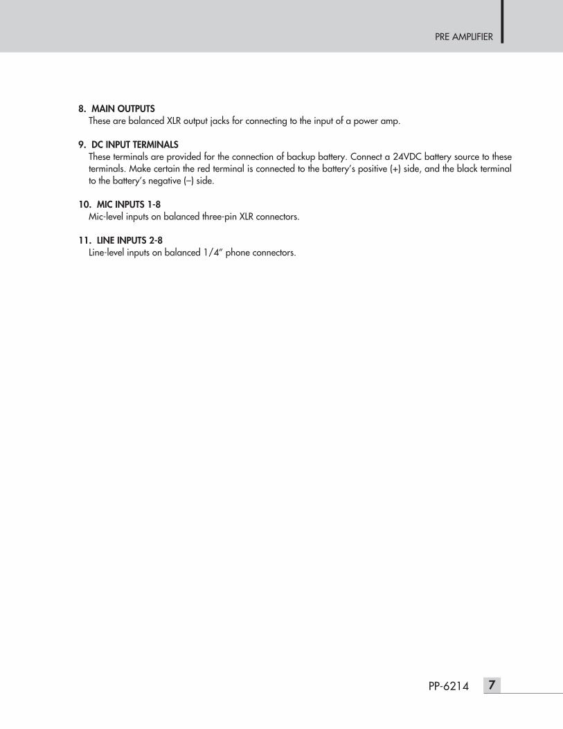
8. MAIN OUTPUTSThese are balanced XLR output jacks for connecting to the input of a power amp.
9. DC INPUT TERMINALSThese terminals are provided for the connection of backup battery. Connect a 24VDC battery source to theseterminals. Make certain the red terminal is connected to the battery’s positive (+) side, and the black terminalto the battery’s negative (–) side.
10. MIC INPUTS 1-8Mic-level inputs on balanced three-pin XLR connectors.
11. LINE INPUTS 2-8Line-level inputs on balanced 1/4” phone connectors.

PRE AMPLIFIER
8 PP-6214
ApplicationsApplications
FUSE
T400mAL/250V
DC INPUT
24V
LINE
INSERT INSERTREC OUTPUT PRIORITY INPUT
MIC MIC MIC MIC MIC MIC MIC MIC
CH 2
OUTPUT OUTPUT
MUTE
ON
OFF
LINE LINE LINE LINE LINE LINE
CH 5 CH 4 CH 3 CH 2 CH 1CH 8 CH 7 CH 6
CH 1
CH 12 CH 10CH 11 CH 9
2 1 2 1
www.inter-m.com
SN
OC03OC03 0210
MODEL NO. PE-9103A
MADE IN KOREA
CHIME/SIREN
FUSE
T315mAL / 250V
~AC INPUT
120V 60Hz, 11W
DC INPUT
24V
UNBAL / 75
LOOP
ANT.
LR
STEREOMONO(BAL)MONO(BAL)
VARIABLEFIXED
SN
www.inter-m.com
OUTPUT ANT
RESET
FM AMDIGI-LINK
PB-6207
PE-6103
PP-6214
PD-6359
AC INPUT
BATTERY
(DC 24V)
TUNER
PC-6335
PA-6312
PA-6324
MIC
CD-6208
DC INPUT
24V
SN
2 TONE
WESTMINSTER
OUTPUT REMOTE CHIME

PRE AMPLIFIER
9PP-6214
Block DiagramBlock Diagram
PRE AMPLIFIER
10 PP-6214
SpecificationsSpecifications
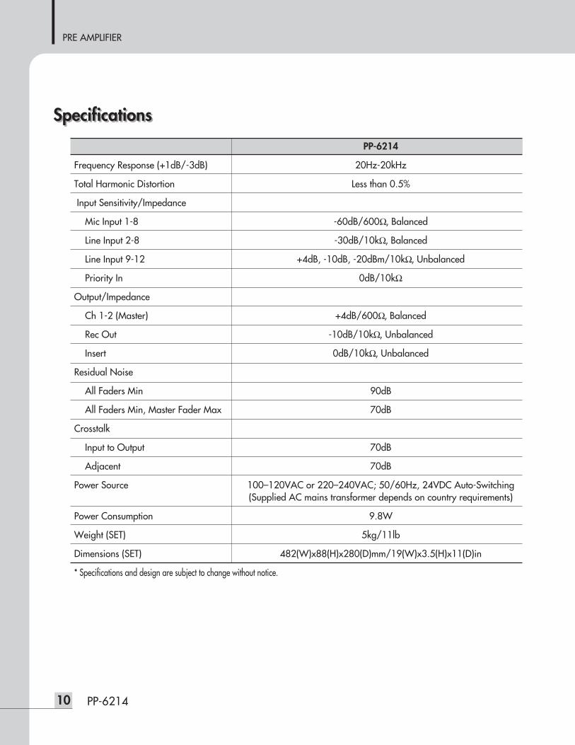
PP-6214
Frequency Response (+1dB/-3dB) 20Hz-20kHz
Total Harmonic Distortion Less than 0.5%
Input Sensitivity/Impedance
Mic Input 1-8 -60dB/600Ω, Balanced
Line Input 2-8 -30dB/10kΩ, Balanced
Line Input 9-12 +4dB, -10dB, -20dBm/10kΩ, Unbalanced
Priority In 0dB/10kΩ
Output/Impedance
Ch 1-2 (Master) +4dB/600Ω, Balanced
Rec Out -10dB/10kΩ, Unbalanced
Insert 0dB/10kΩ, Unbalanced
Residual Noise
All Faders Min 90dB
All Faders Min, Master Fader Max 70dB
Crosstalk
Input to Output 70dB
Adjacent 70dB
Power Source 100–120VAC or 220–240VAC; 50/60Hz, 24VDC Auto-Switching(Supplied AC mains transformer depends on country requirements)
Power Consumption 9.8W
Weight (SET) 5kg/11lb
Dimensions (SET) 482(W)x88(H)x280(D)mm/19(W)x3.5(H)x11(D)in
* Specifications and design are subject to change without notice.

PRE AMPLIFIER
11PP-6214
440
482
280
88
※ DIMENSIONS

PRE AMPLIFIER
ServiceService
ProceduresTake steps to insure the problem is not related to operator error or other products within the system. Informationprovided in the troubleshooting portion of this manual may help with this process. Once it is certain that theproblem is related to the product contact your warranty provider as described in the warranty section of thismanual.
SchematicA Schematic is available by contacting your warranty provider.
Parts ListA Parts List is available by contacting your warranty provider.
WarrantyWarranty
Warranty terms and conditions vary by country and may not be the same for all products. Terms and conditionsof warranty for a given product may be determined first by locating the appropriate country which the productwas purchased in, then by locating the product type.
To obtain specific warranty information and available service locations contact Inter-M directly or theauthorized Inter-M Distributor for your specific country or region.
Variations and OptionsVariations and Options
VariationsVariations of this product exist to reflect the variations in AC power requirements throughout the world. Productsupplied through local sources are compatible with local AC power requirements.
Options No optional items are available for this product.
12 PP-6214

MADE IN KOREAJune 2012 130445
Inter-M, Ltd. (Korea) began operations in 1983.
Since then, Inter-M has grown to become one of the largest manufacturers of professional audio and commercial sound electronics equipment in the world.
Inter-M has gained worldwide recognition for its own branded products, as well as private label manufacturing of electronics sold under other names (OEM).
The company is no longer just a Korean company, but rather a global company that is truly international in scope, with factories and offices in Korea and China, and sales and marketing operations located in Japan, Europe, and the U.S.A.
With more than 850 employees around the globe,Inter-M is well-poised for further growth and expansion.
Inter-M Americas, Inc. 13875 Artesia Blvd. Cerritos, CA 90703 USATEL : +1-562-921-0313, FAX : +1-562-921-0370Home Page : http://www.inter-m.net, E-mail : [email protected]
Inter-M CorporationSeoul OFFICE:653-5 BANGHAK-DONG, DOBONG-KU, SEOUL, KOREA TEL : +82-2-2289-8140~8, FAX : +82-2-2289-8149Home Page : http://www.inter-m.com, E-mail : [email protected]