pppwc / xuslpppwh - ip69k enclosure
TRANSCRIPT
RUN
STOP
START
1 2
RUN
STOP
WEAK
START
1 2
RUN
TEST
ERR
XUSLpEppp
RUN
STOP
WEAK
START
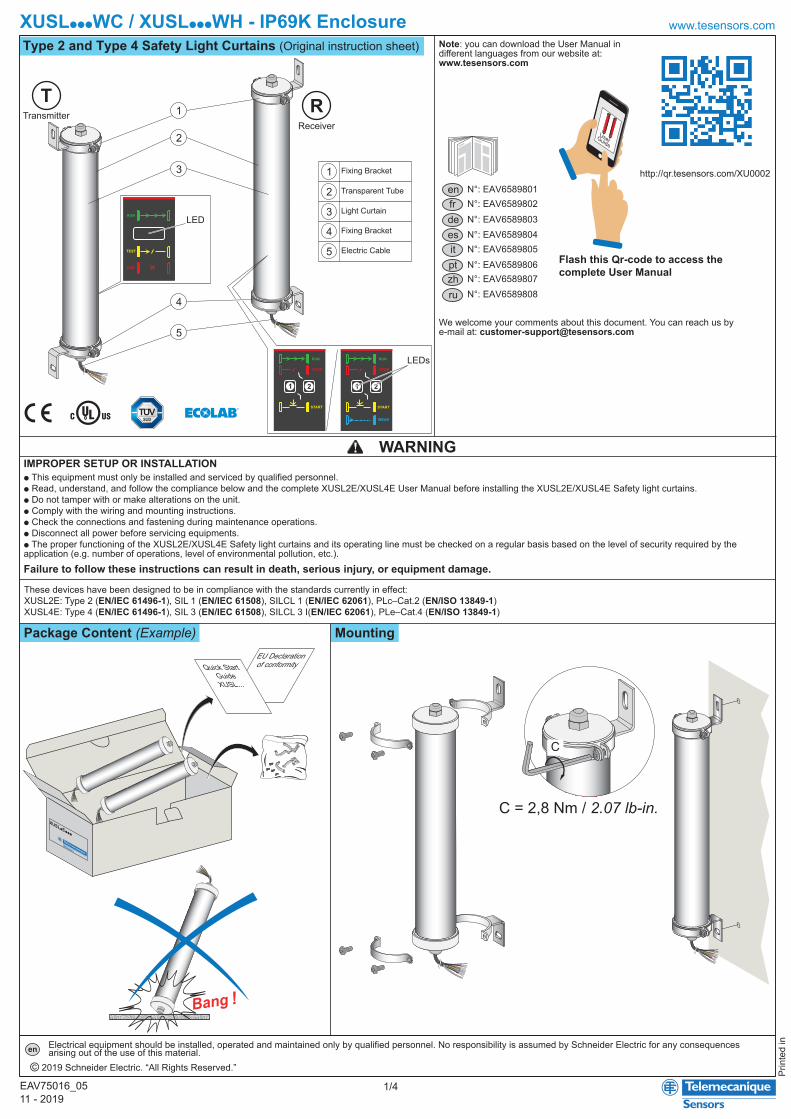
XUSLpppWC / XUSLpppWH - IP69K Enclosure
Prin
ted
in
Type 2 and Type 4 Safety Light Curtains (Original instruction sheet)
Mounting
www.tesensors.com
1/411 - 2019EAV75016_05
Electrical equipment should be installed, operated and maintained only by qualified personnel. No responsibility is assumed by Schneider Electric for any consequencesarising out of the use of this material.en
© 2019 Schneider Electric. “All Rights Reserved.”
These devices have been designed to be in compliance with the standards currently in effect:XUSL2E: Type 2 (EN/IEC 61496-1), SIL 1 (EN/IEC 61508), SILCL 1 (EN/IEC 62061), PLc–Cat.2 (EN/ISO 13849-1)XUSL4E: Type 4 (EN/IEC 61496-1), SIL 3 (EN/IEC 61508), SILCL 3 I(EN/IEC 62061), PLe–Cat.4 (EN/ISO 13849-1)
http://qr.tesensors.com/XU0002
Failure to follow these instructions can result in death, serious injury, or equipment damage.
WARNINGIMPROPER SETUP OR INSTALLATIONp This equipment must only be installed and serviced by qualified personnel.p Read, understand, and follow the compliance below and the complete XUSL2E/XUSL4E User Manual before installing the XUSL2E/XUSL4E Safety light curtains.p Do not tamper with or make alterations on the unit.p Comply with the wiring and mounting instructions.p Check the connections and fastening during maintenance operations.p Disconnect all power before servicing equipments.p The proper functioning of the XUSL2E/XUSL4E Safety light curtains and its operating line must be checked on a regular basis based on the level of security required by the application (e.g. number of operations, level of environmental pollution, etc.).
enfr
esde
itptzhru
Note: you can download the User Manual in different languages from our website at: www.tesensors.com
We welcome your comments about this document. You can reach us by e-mail at: [email protected]
N°: EAV6589801N°: EAV6589802N°: EAV6589803
N°: EAV6589806N°: EAV6589807
N°: EAV6589804N°: EAV6589805
Package Content (Example)
Flash this Qr-code to access thecomplete User Manual
TransmitterReceiver
T R1
2
3
4
5
1
2
3
4
5
Fixing Bracket
Fixing Bracket
Transparent Tube
Light Curtain
Electric Cable
LED
LEDs
EU Declaration of conformityQuick Start
GuideXUSL...
C = 2,8 Nm / 2.07 lb-in.
RUN
STOP
WEAK
START
RUN
STOP
WEAK
START
C
RUN
STOP
WEAK
START
RUNSTOP
WEAK
START
RUNST
OP
WEA
K
START
UserGuide
RUN
TEST
ERR
RUNSTOP
WEAK
START
N°: EAV6589808
XUSLpppWC / XUSLpppWH - IP69K Enclosure
2/4EAV75016_05
www.tesensors.com
Wiring diagrams
Dimensions
Failure to follow these instructions can result in death, serious injury, or equipment damage.
WARNINGIMPROPER CONNECTIONp The XUSL2E/XUSL4E light curtain system must be powered by a safety extra low voltage (SELV) or a protected extra low voltage (PELV)p The XUSL2E/XUSL4E light curtain system is designed for use only on a 24 Vdc negative ground electrical system.p Never connect the XUSL2E/XUSL4E light curtain system to a positive ground system.p Never connect the ground (here the Functional Earth FE) with the 0 Volt reference of the safety extra low voltage (SELV) power supply.p The XUSL2E/XUSL4E safety light curtains must be connected using both safety outputs.p A single safety output, if it fails, may not stop the machine.
Note:The XUSL2E/XUSL4E light curtain system operates directly from a 24 Vdc ±20% power supply. The power supply must meet the requirements of EN/IEC 60204-1 and EN/IEC 61496-1. The SELV Schneider Electric part number ABL8RPS24••• is recommended.
WH: WhiteBK: BlackBN: BrownGN: GreenYE: YellowGY: GreyPK: PinkBU: BlueRD: RedVT: violet
T R
mmin.
32012.60
47018.50
62024.41
77030.31
92036.22
107042.13
122048.03
137053.94
152059.84
167065.75
76029.92
106041.73
116045.67
290 440 590 740 890 1040 1190 1340 1490 1640 730 1030 113011.42 17.32 23.23 29.13 35.04 40.94 46.85 52.76 58.66 64.57 28.74 40.55 44.49
XUSLpE
A
B
C (± 3 mm)
D
ppp016 ppp031 ppp046 ppp061 ppp076 ppp091 ppp106 ppp121 ppp136 ppp151 2B 3B 4B
315 465 615 765 915 1065 1215 1365 1515 1665 755 1055 1155 12.4 18.31 24.21 30.12 36.02 41.93 47.83 53.74 59.65 65.55 29.72 41.53 45.47337 487 637 787 937 1087 1237 1387 1537 1687 777 1077 1177
13.27 19.17 25.08 30.98 36.89 42.8 48.7 54.61 60.51 66.41 30.59 42.4 46.34
182071.65
197077.56
1790 194070.47 76.38
ppp166 ppp181
1815 196571.46 77.361837 198772.32 78.23
762.99562.2
75 2.95
B
D
A
C
Ø = 5,8 mm (max.)Ø = 0.23 in. (max.)
46 1.81
26±1
1.04±0.4
RU
N
TEST
ERR
Manual start/restart without EDM feedback loopAutomatic start/restartwithout EDM feedback loop
Automatic start/restartwith EDM feedback loop
0 Vdc+24 Vdc
1
2
3
4
5
6
7
8FE
0 Vdc
+24 Vdc
Conf._AK1_K2Feedback_Restart
Conf._B
OSSD1
OSSD2
XUSLppp
R
RESTART
Manual start/restart with EDM feedback loop
Transmitter - Low range connection
0 Vdc+24 Vdc 1
2
3
4
5FE
0 Vdc
+24 Vdc
Conf. 0
Conf. 1
XUSLppp
T
Transmitter - high range connection
0 Vdc+24 Vdc 1
2
3
4
5FE
0 Vdc
+24 Vdc
Conf. 0
Conf. 1
XUSLppp
T
Wire color Description
OSSD1
K1_K2 Feedback/RestartConfiguration_B0 VdcFE
OSSD2
WH
BU
BNGN
PK
0 V (heating system)24 V a / c (heating system)VT
BK
GYYE
RD
WH
BU
BNGN
PKGYYE
RD
+ 24 Vdc
Configuration_A
withoutheatingsystem
withheatingsystem
Wire color Description
+ 24 Vdc
FE0 V (heating system)24 V a / c (heating system)-
0 Vdc
BNBN
RD
WHWHBUBU
YEGYGYGN
PK
Configuration_0
Configuration_1
withoutheatingsystem
withheatingsystem
BK
BN
WH
BU
GY
BK
BN
WH
BU
GY
BK
0 Vdc+24 Vdc
1
2
3
4
5
6
7
8FE
0 Vdc
+24 Vdc
Conf._AK1_K2Feedback_Restart
Conf._B
OSSD1
OSSD2
XUSLppp
RBN
GN
GY
WH
BU
YE
RD
PK
BN
GN
GY
WH
BU
YE
RD
PK
1
2
3
4
5
6
7
8FE
0 Vdc
+24 Vdc
Conf._A
K1_K2Feedback_Restart
Conf._B
OSSD1
OSSD2
XUSLppp
R
RESTART
K2
K1
0 Vdc+24 Vdc BN
GN
GY
WH
BU
YE
RD
PK
0 Vdc+24 Vdc
K2
K1
1
2
3
4
5
6
7
8FE
0 Vdc
+24 Vdc
Conf._AK1_K2Feedback_Restart
Conf._B
OSSD1
OSSD2
XUSLppp
R
BN
GN
GY
WH
BU
YE
RD
PK

XUSLpppWC / XUSLpppWH - IP69K Enclosure
3/4EAV75016_05
www.tesensors.comConnection Schematics
Failure to follow these instructions can result in death, serious injury, or equipment damage.
WARNINGUNINTENDED EQUIPMENT OPERATIONThe external KM1 and KM2 contactors must have force-guided contacts.
WH: WhiteBK: BlackBN: BrownGN: GreenYE: YellowGY: GreyPK: PinkBU: BlueRD: RedVT: violet
T
R
+ 24 Vdc
FE0 V (withheating system)
0 Vdc
BN
24 V a / c(with heatingsystem)
RD
WHBU
YE
GYBK or GN
-PK
Configuration_0
Configuration_1
OSSD1
KM1_KM2Feedback/Restart
OSSD2
WHBNGN
GY
YE
Configuration_B0 VdcFE
BUPK
0 V (with heatingsystem)24 V a / c (withheating system)
VT
BK
RD
+ 24 Vdc
Configuration_A
Standalone Application
Connecting with a SafetyControl Unit: XPSU-AF
Connecting with a SafetyController: XPSMCM
(1) : Use of arc suppressors for KM1 & KM2 is recommended
KM1 KM2
KM2
KM1
Start
N L
F1
1 23 45
XUSLppp
Transmitter
FE 0 Vdc +24 Vdc Conf. 0 Conf. 1
12 345 678
XUSLppp
Receiver
FE 0 Vdc +24 Vdc Conf._AK1_K2
Feedback_Restart Conf._B OSSD1 OSSD2
Low range
Power circuit
KM1
KM2
(1) (1)
GND
GND N L
0V 24V
ABL8RPS24p
Power circuit
KM1
KM2
0V
0V
+24V
F3Low range
KM2
KM1Start
F4 F5
KM1 KM2
F2
+24V
0V
AC/DC
DC
DC+ CH+
Input
DC+ CH+
Start
DC+(-) CH+(-)
Input (1)
K1
K2Power-Supply
A1 A2 S11 S12 Y1 Y2
S21 S22 Z1B2
13
14
23
24
33
34
EXT
XPSUAF
1 23 45
XUSLppp
T
FE 0 Vdc +24 Vdc Conf. 0 Conf. 1
12 345 678XUSLppp
R
FE 0 Vdc +24 Vdc Conf._AK1_K2
Feedback_Restart Conf._B OSSD1 OSSD2
N L
F1
0V +24V
GND
GND N L
0V 24V
ABL8RPS24p
(1) Pulsed output for diagnostics
(1)
+24V
0V
1
23
4
56
7
89
10
11
12
19
2021
22
23
24
13
1415
16
1718
OUT_TEST1
OUT_TEST2
OUT_TEST3
OUT_TEST4
+24 Vdc
Master_Enable1
Master_Enable2
OSSD1_B
OSSD1_A
OSSD2_B
OSSD2_A
OUT_STATUS1
OUT_STATUS2
INPUT1
INPUT2
INPUT3
INPUT4
INPUT5
INPUT6
INPUT7
INPUT8
0 Vdc
RESTART1
RESTART2
XPSM
CM
CP0
802
0V
+24VF2
KM2
KM1
KM2 KM
1Re
start
Feed
back
1 23 45
XUSLppp
T
FE 0 Vdc +24 Vdc Conf. 0 Conf. 1
12 345 678XUSLppp
R
FE 0 Vdc +24 Vdc Conf._AK1_K2
Feedback_Restart Conf._B OSSD1 OSSD2
0V +24V
F3Low range
N L
F1
0V +24V
GND
GND N L
0V 24V
ABL8RPS24p
Power circuit
KM1
KM2

XUSLpppWC / XUSLpppWH - IP69K Enclosure
4/4EAV75016_05
www.tesensors.comAlignment procedure
LEDs Status
CharacteristicsProduct certifications CE, cULus, TüV, EAC, RCMAmbient air temperature
Shock and Vibration resistance Conforming to EN/IEC 61496-1:p Shock: 10 gp Impulse: 16 msp Vibration: 10...55 Hzp Amplitude: 0.35 ± 0.05 mm (0.0014 ± 0.00020 inches)
Light source Infrared λ = 950 NmResistance to light disturbance Conforming to EN/IEC 61496-2.Power Supply 24 Vdc ± 20% - 2 A
The power supply must meet the requirements of EN/IEC 60204-1 relative to SELV/PELV power supply
Safety outputs (OSSD) Two PNP - 400 mA per output @ 24 Vdc, drop out voltage <0.5 Vdc (Integrated arc suppressors), leakage current(OFF state) < 2 mA. Load capacity 0.82μF under 24 Vdc
Resistance to interference Level depends if the product is Type 2 or Type 4 conforming to EN/IEC 61496-1.Input power supply Transmitter: 42 mA - Receiver: 900 mA (Including OSSD current)Maximum current consumption (no load) Transmitter: 42 mA - Receiver: 83 mA
Degree of protection Conforming to EN/IEC 60529: IP65, IP67 - DIN 40050: IP69K
Operation
Storage Type2 and 4 - Standard and Long Sensing Range - With and without heating system: - 30…70 °C (- 22 °F to 158 °F)
Note: More characteristics in the User Manual
-20°C…+55°C (- 4 °F to 131 °F)
Type 2 IP69K without heating systemNormal sensing range
Normal sensing range
-30°C...+55°C (- 22 °F to 131 °F)
-30°C...+55°C (- 22 °F to 131 °F)
Long sensing range
XUSL2E30HpppNWCType 2 IP69K with heating systemXUSL2E30HpppNWHType 4 IP69K without heating systemXUSL4E14FpppNWCType 4 IP69K with heating systemXUSL4E14FpppNWH
-20°C…+55°C (- 4 °F to 131 °F)
-30°C...+55°C (- 22 °F to 131 °F)
Type 4 IP69K without heating systemXUSL4EpBBpppLWCXUSL4E30HpppLWCXUSL4EpBBpppLWHXUSL4E30HpppLWH Type 4 IP69K with heating system
RUN
TEST
ERR
T R RUN
STOP
START
1 2
RUN
STOP
WEAK
START
1 2
T R T R T R
T R
T R
L1
L2
L1 = L2
1 2 1
T R
Red Yellow
Yellow
Green BlueBlueBlue -Yellow alternate
Red
RedGreen
GreenGreen
Green Yellow flashes Yellow flashes
(*): When weak signal blue display is available (Type4 finger & long range models). In case of weak signal detected.
(*)
LEDs MeaningOSSD
Power-On Initialization Test.OFF Normal operation.ON Detection zone interrupted.OFFDetection zone clear, waiting for restart.OFF
Detection zone clear, waiting for KM1_KM2 feedback.OFF
2
GreenRed
YellowOFF
(*)
BlueYellow
OFFOFF
OFF OFF
Blue and/orYellow (*)
Green/Yellowor Red (*)
Red
Red
Orange
Green
Green
Red flashes Red flashes
Yellow flashes
OFF
(*) Weak signal (low signal received) only with type 4finger detection and long range models.
OFFOFF
Test state (simulation of a detection zone interruption).
Master: Detection zone clear Slave: Detection zone interrupted.Fail mode (Error state) For more information,refer to “Troubleshooting” section in the User manual.OFF
OFF
Alternate flashes Alternate
Mission Time (TM) 20 years
OSSDs y 200 µs
PFHD Depends on the models. Refer to the complete User ManualFirst-up time y 2 s
Pulse Duration2,5 ms (Type 4 models) and 500 ms (Type 2 models)Minimum pulse period
1) The transmitter and receiver must be installed with the optical surfaces face to face, connectors oriented in the same way. Perfect alignment of the transmitter and the receiver corresponding beams is mandatory for an optimum functioning, meaning that the transmitter and receiver must have the same height and be parallel. A good positioning will be facilitated by using the provided mounting accessories.The use of LED indicators helps in proper alignment as described below:
- For an easier alignment setting, configure the safety light curtain in Automatic mode. That will avoid to restart the system during the alignment adjustments.- For all models align the transmitter until the green LED is lit on the receiver.- For finger detection and long range models, the blue LED weak signal on the receiver will be useful as well. Firstly, find the zone where the blue LED is lit, indicating an approximate alignment, then fine-tune the setting until the blue LED turns OFF and the green LED is lit.- Do not forget to reconfigure the safety light curtain in Manual start mode if this operating mode is required.
2) If vibrations are to be expected in your applications, it is strongly recommended to use vibration dampers (Available as accessories).