ppt-2 orthographic projection - hame.uk.comhame.uk.com/wcs/material/eng comms/ppt-2... ·...
TRANSCRIPT
HNC Engineering Systems
Orthographic Projection
Engineering CommunicationMike Doyle
DV9N 34

NC Engineering Systems
● What is Orthographic Projection?
● Orthographic projection is a means of representing a three-dimensional (3D) object in two dimensions (2D).
● It is a form of parallel projection, where the view direction is orthogonal to the projection plane.
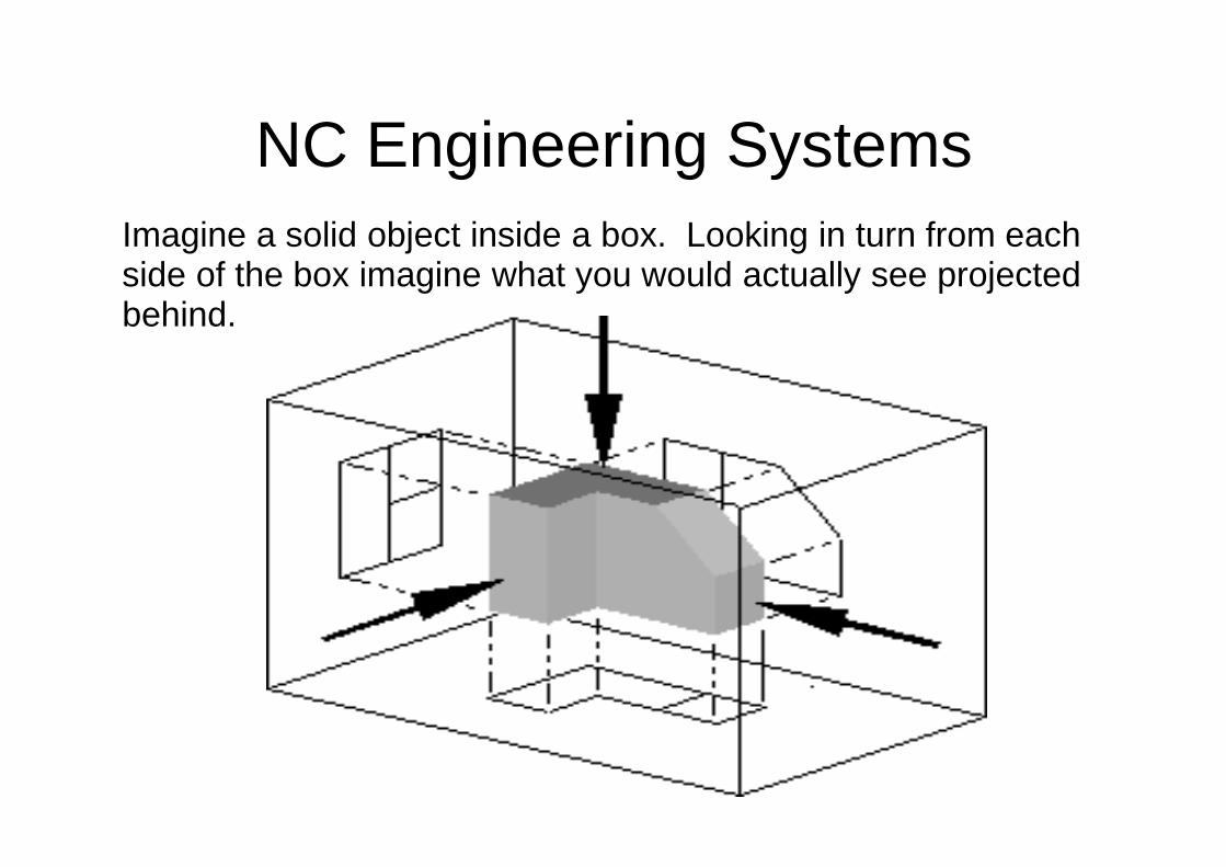
NC Engineering SystemsImagine a solid object inside a box. Looking in turn from each side of the box imagine what you would actually see projected behind.
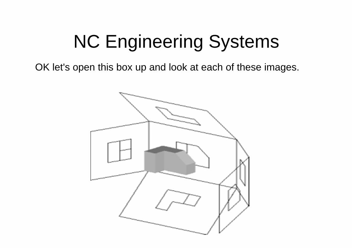
NC Engineering SystemsOK let's open this box up and look at each of these images.

NC Engineering Systems
What you would see is something similar to the diagram below.Six sides of a box flattened out with the 2D representation ofthe 3D block.

NC Engineering Systems

NC Engineering SystemsThe 3D interpretation of the symbol can be deduced byenvisioning a solid truncated cone (Mnemonic: a "gift-wrappedmegaphone"), standing upright with its large end on the floor andthe small end upward. The top view is therefore two concentriccircles ("doughnut"). In particular, the fact that the inner circle isdrawn with a solid line instead of a dashed line this shows theview as the top view, not the bottom view.Any lines we can see are shown as solid lines – any lines that cannot be seen [hidden] are shown as dashed lines.
NC Engineering Systems
* In first-angle projection, the "top" view is pushed down to the floor, and the "front" view is pushed back to the rear wall; the intersection line between these two planes is therefore closest to the large end of the cone, hence the first-angle symbol shows the cone with its large end open toward the doughnut.
* In third-angle projection, the "top" view is pulled up to the ceiling, and the "front" view is pulled forward to the front wall; the intersection line between the two planes is thus closest to the small end of the cone, hence the third-angle symbol shows the cone with its large end away from the doughnut.

NC Engineering Systems
Let's have a look at some objects:- [End Elevation]

NC Engineering Systems
Side Elevation

NC Engineering Systems
Looking down on top [Plan View]
NC Engineering Systems
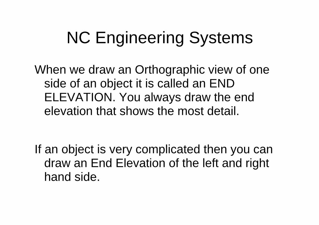
When we draw an Orthographic view of one side of an object it is called an END ELEVATION. You always draw the end elevation that shows the most detail.
If an object is very complicated then you can draw an End Elevation of the left and right hand side.
NC Engineering Systems
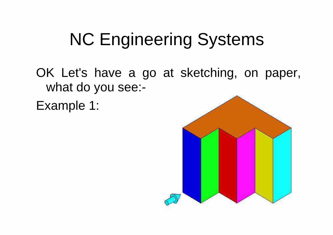
OK Let's have a go at sketching, on paper,what do you see:-
Example 1:

NC Engineering Systems
Example 1:

NC Engineering Systems
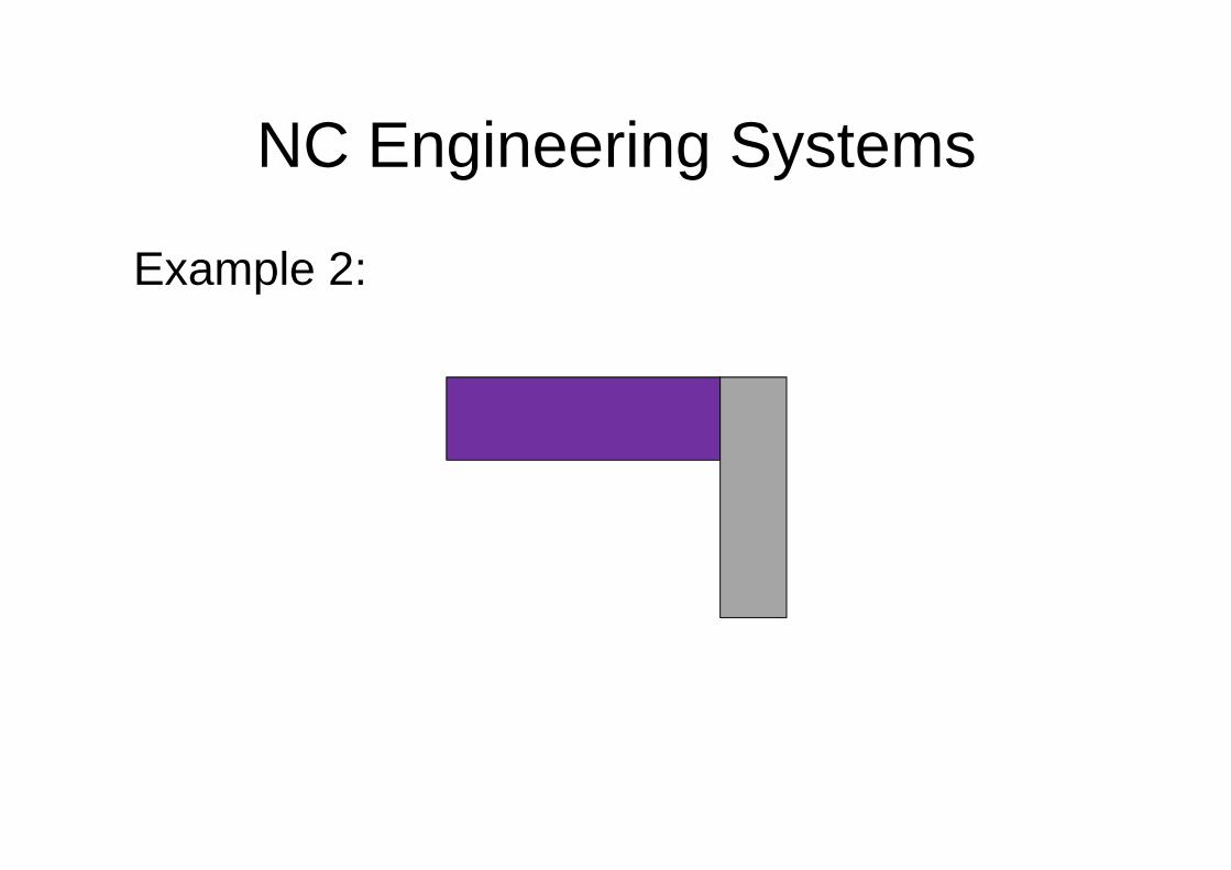
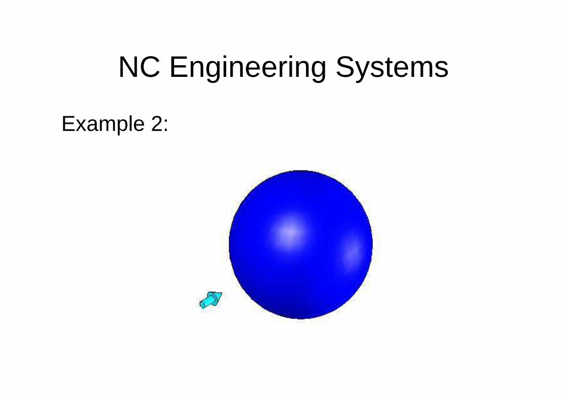
Example 2:
NC Engineering Systems
Example 2:
NC Engineering Systems
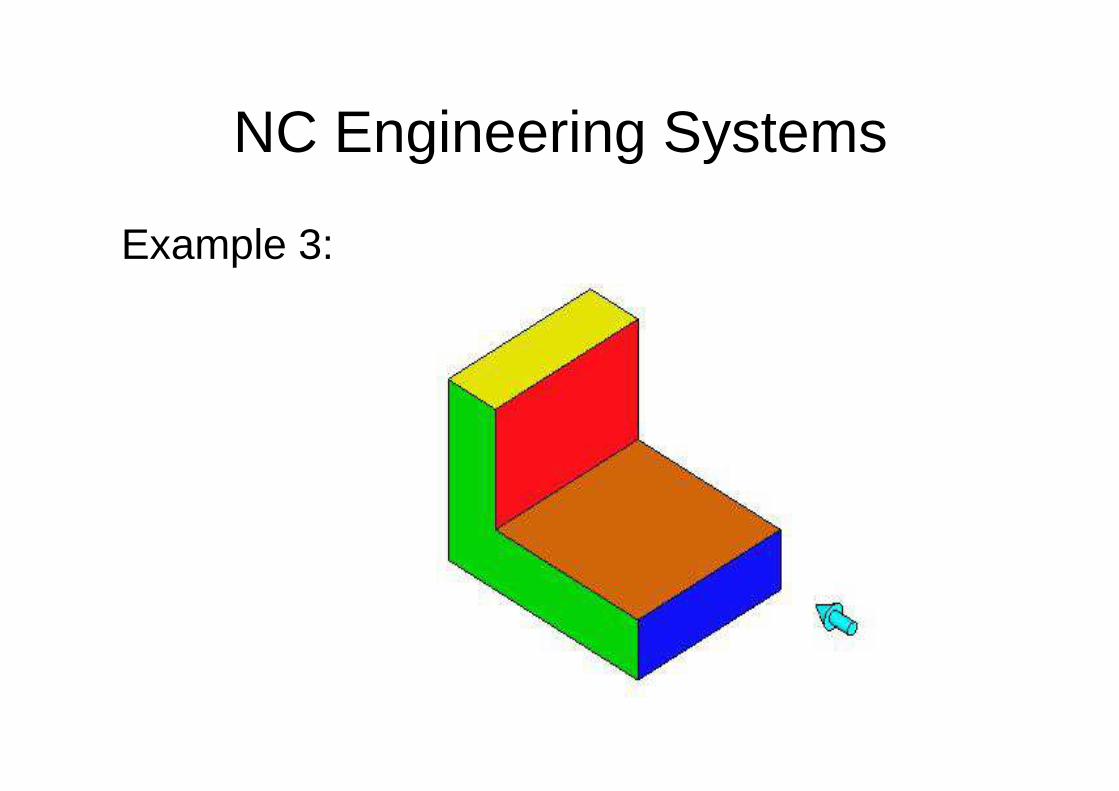
Example 3:

NC Engineering Systems
Example 3:

NC Engineering Systems
Example 4:

NC Engineering Systems
Example 4:

NC Engineering Systems
Example 5:

NC Engineering Systems
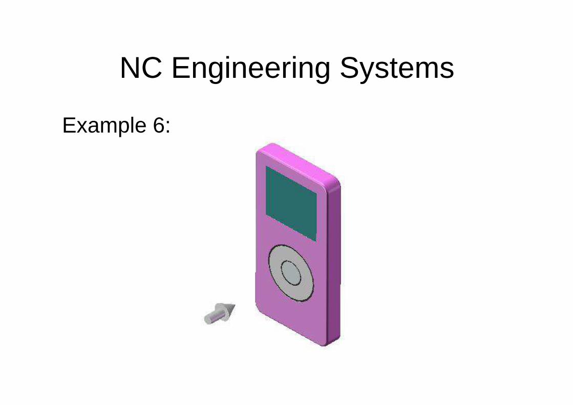
Example 6:
NC Engineering Systems
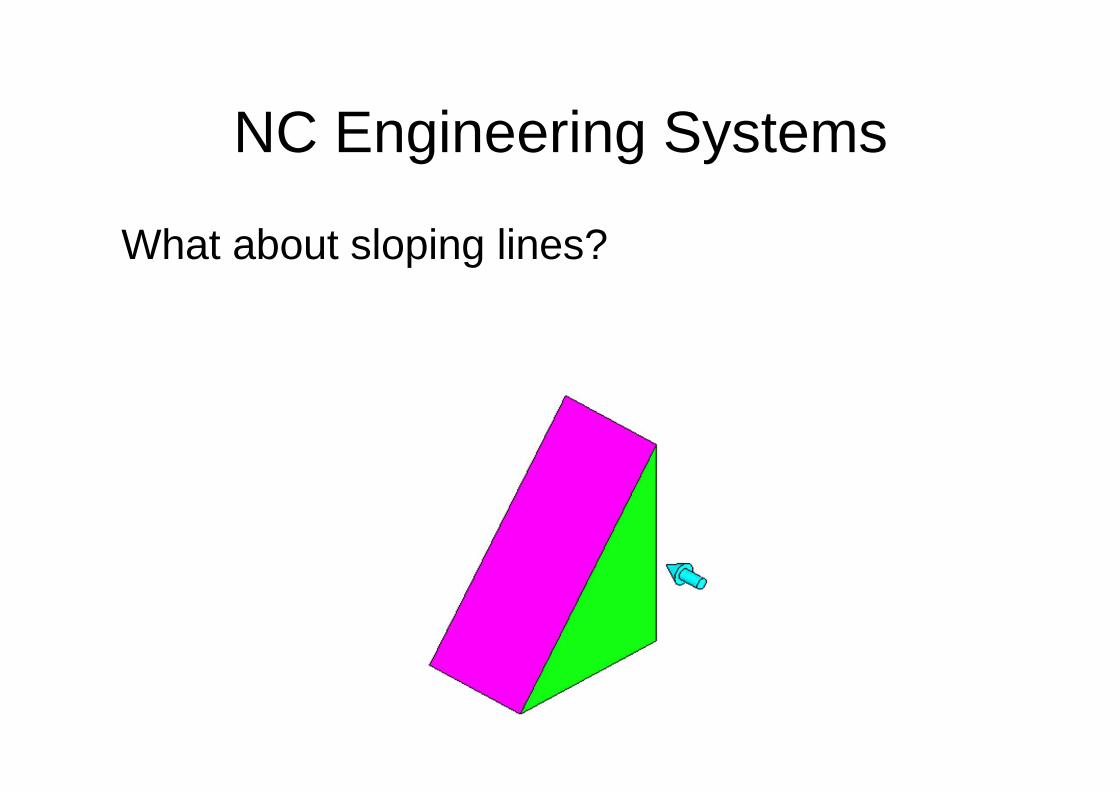
What about sloping lines?
NC Engineering Systems
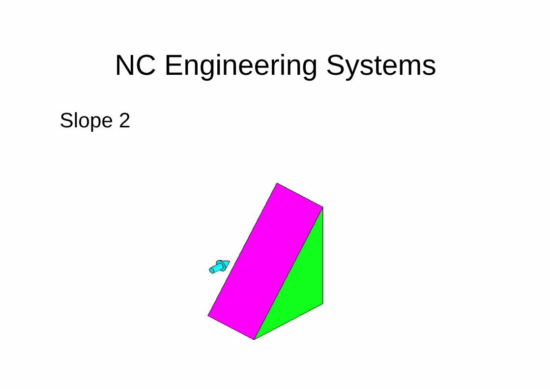
Slope 2

NC Engineering Systems
Slope 3:
NC Engineering Systems
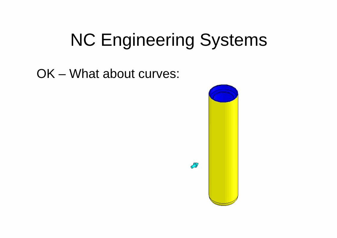
OK – What about curves:
NC Engineering Systems
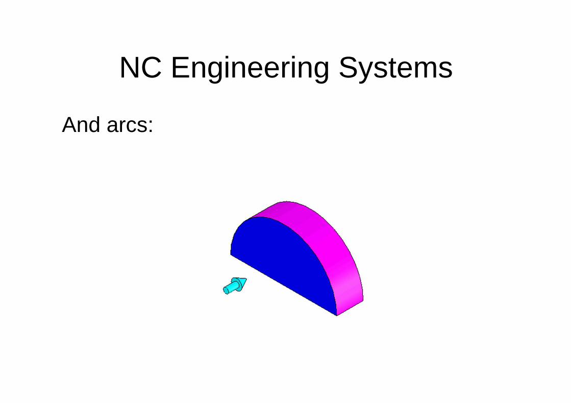
And arcs:
NC Engineering Systems
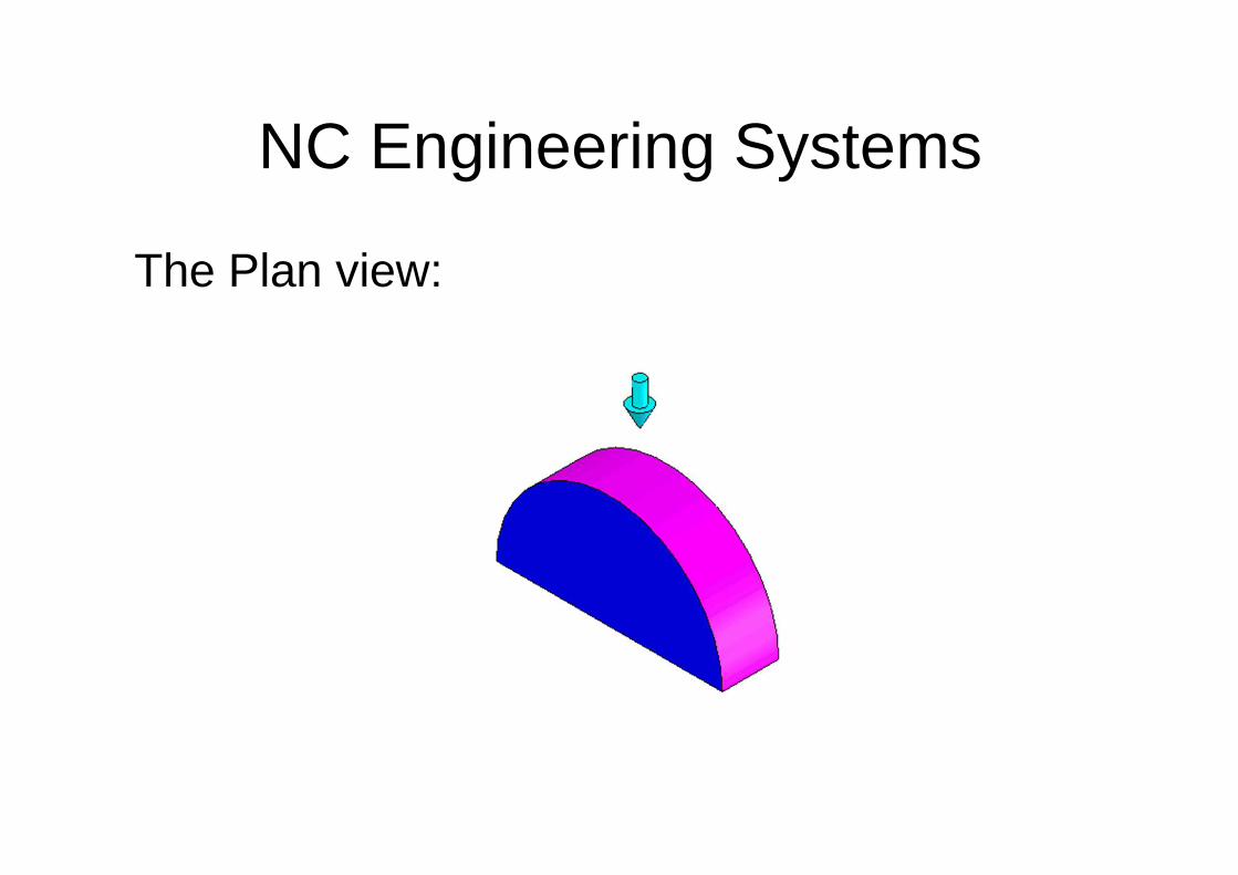
The Plan view:
NC Engineering Systems
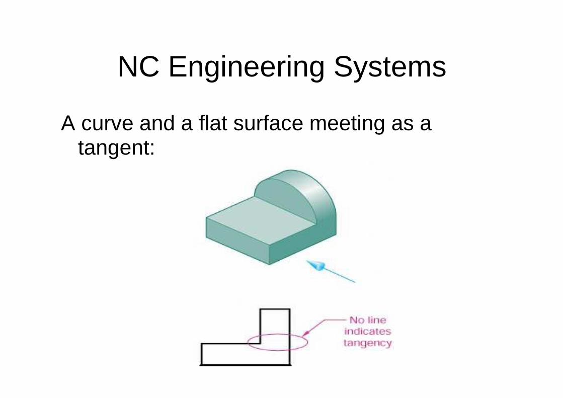
A curve and a flat surface meeting as a tangent:

NC Engineering Systems
A curve and block meeting with no tangent:

NC Engineering Systems
Some more examples for you to sketch: Example 1:
NC Engineering Systems
Example 2:

NC Engineering Systems
● Example 3:

NC Engineering Systems
Example 4:

NC Engineering Systems
Example 5:
NC Engineering Systems
Example 6:

Standard Paper Sizes