practical advanced periodontal surg
TRANSCRIPT

Practical Advanced PeriodontalSurgery
Serge Dibart
Practical Advanced Periodontal Surgery offers astep-by-step guide to cutting-edge surgicaltechniques as well as interdisciplinarytreatment approaches in periodontology. Itdetails procedures in a practical, succinct,thorough, and accessible way, profiling morecomplex and advanced procedures through auser-friendly and highly visual format. Bypresenting an innovative approach to eachtreatment modality, Practical AdvancedPeriodontal Surgery provides predictablesolutions to complex daily dental challenges.
Practical Advanced Periodontal Surgeryexplores the expanding scope ofperiodontics, equipping the reader with aclear understanding of the techniquesinvolved and the rationale needed tocomprehend their context. The bookconcentrates on some of the morechallenging and advanced surgical aspects ofperiodontology, profiling procedures as theyrelate to other disciplines, such asorthodontics, restorative and implantdentistry, oral medicine, and also other newand innovative approaches, such as implantpapillary reconstruction and sinusaugmentation through tissue engineering.
A truly unique book that presents vital newinformation on a range of complex topics in aconcise and reader-friendly format, this will bean essential addition to the library of practicingor studying periodontists, as well as cliniciansand students of other areas of dentistry.
■ Practical and easy to use step-by-step format
■ Highly illustrated with clinical photographydetailing each surgical procedure
■ Profiles the most innovative techniques inperiodontal surgery
■ Introduces and explains advanced surgicalprocedures
■ Features pros and cons as well aslimitations of various procedures andtreatments, their potential complications,and their resolution
■ Focuses on interdisciplinary treatment
Other titles of interest:
Practical Periodontal Plastic SurgerySerge Dibart and Mamdouh KarimaISBN-13 978-0-8138-2268-6
Manual of Minor Oral Surgery for the General DentistEdited by: Karl KoernerISBN-13 978-0-8138-0559-7
Practical Advanced Periodontal Surgery
Serge Dibart
PracticalAdvancedPeriodontal SurgerySerge Dibart
Dibart Advanced PPC Cvr 07-24-07.qxd 24.07.07 6:45 pm Page 1
PRACTICAL ADVANCED PERIODONTAL SURGERY

PRACTICAL ADVANCED PERIODONTAL SURGERY
Serge Dibart, DMDProfessorClinical Director Department of Periodontology and Oral BiologyBoston University School of Dental MedicineBoston, MA

Serge Dibart, DMD, is clinical director of the periodontalresidency program at Boston University Goldman School ofGraduate Dentistry.
© 2007 by Blackwell Munksgaard,a Blackwell Publishing Company
Editorial Offices:Blackwell Publishing Professional,2121 State Avenue, Ames, Iowa 50014-8300, USA
Tel: +1 515 292 0140 9600 Garsington Road, Oxford OX4 2DQ
Tel: 01865 776868
Blackwell Publishing Asia Pty Ltd, 550 Swanston Street, Carlton South, Victoria 3053, Australia
Tel: +61 (0)3 9347 0300
Blackwell Wissenschafts Verlag, Kurfürstendamm 57, 10707 Berlin, Germany
Tel: +49 (0)30 32 79 060
The right of the Author to be identified as the Author of thisWork has been asserted in accordance with the Copyright,Designs and Patents Act 1988.
All rights reserved. No part of this publication may bereproduced, stored in a retrieval system, or transmitted, inany form or by any means, electronic, mechanical, photo-copying, recording or otherwise, except as permitted by theUK Copyright, Designs and Patents Act 1988, without theprior permission of the publisher.
DisclaimerThe contents of this work are intended to further generalscientific research, understanding, and discussion only and are not intended and should not be relied upon asrecommending or promoting a specific method, diagnosis,or treatment by practitioners for any particular patient. The publisher and the author make no representations orwarranties with respect to the accuracy or completeness of the contents of this work and specifically disclaim allwarranties, including without limitation any impliedwarranties of fitness for a particular purpose. In view ofongoing research, equipment modifications, changes ingovernmental regulations, and the constant flow ofinformation relating to the use of medicines, equipment, and devices, the reader is urged to review and evaluate the
information provided in the package insert or instructions foreach medicine, equipment, or device for, among otherthings, any changes in the instructions or indication ofusage and for added warnings and precautions. Readersshould consult with a specialist where appropriate. The factthat an organization or Website is referred to in this work asa citation and/or a potential source of further informationdoes not mean that the author or the publisher endorsesthe information the organization or Website may provide orrecommendations it may make. Further, readers should beaware that Internet Websites listed in this work may havechanged or disappeared between when this work waswritten and when it is read. No warranty may be created or extended by any promotional statements for this work.Neither the publisher nor the author shall be liable for anydamages arising herefrom.
First published 2007 by Blackwell Munksgaard, a BlackwellPublishing Company
Library of Congress Cataloging-in-Publication Data
Practical advanced periodontal surgery / [edited by] Serge Dibart.
p. ; cm.Includes bibliographical references and index.ISBN 978-0-8138-0957-1 (alk. paper)1. Periodontium—Surgery. I. Dibart, Serge.
[DNLM: 1. Periodontium—surgery. 2. Oral SurgicalProcedures, Preprosthetic—methods. 3. Periodontics—methods. WU 240 P895 2007]
RK361.P73 2007617.6�32—dc222007019841
978-0-8138-0957-1
Set by Data ManagementPrinted and bound by C.O.S. Printers PTE LTD
For further information on Blackwell Publishing, visit our website: www.blackwellpublishing.com
The last digit is the print number: 9 8 7 6 5 4 3 2 1
List of Contributors vii
Acknowledgments ix
01. Introduction 3Thomas Van Dyke
02. Bone Physiology and Metabolism 5Jean-Pierre Dibart
Bone Composition 5Bone Types 5Bone Formation 5Bone Density Measuring Techniques 8Implications for Dental Treatments 8
03. The Wound-Healing Process 13Albert Price
Anatomic Review (Emphasis on Vascular Supply) 13The Tissues and Their Vascular Supply 13Alveolar and Basal Bone 14Normal Soft Connective Tissues 16Cementum 19Normal Epithelial Structure 19The Wound-Healing Process Per Se 20
04. The Contribution of Periodontics to 23Orthodontic TherapyDonald J. Ferguson, M. Thomas Wilcko, William M. Wilcko, and M. Gabriela Marquez
Periodontally Accelerated Osteogenic Orthodontics (PAOO) 23
History 23Indications 23Biological Rationale 27Periodontally Accelerated Osteogenic
Orthodontics in the Treatment of Crowding 28Rapid Recovery of Impacted Teeth 28Recovery of Labially Impacted Canines 29Recovery of Deep Palatally Impacted Canines 35Periodontal Surgical Procedures for Orthodontic
Access, Aesthetics, and Stability 38Miniscrew Implants for Orthodontic Anchorage 43
History 43Indications 43Armamentarium 47Complications 49
05. The Contribution of Periodontics to 51Endodontic Therapy: The Surgical Management of Periradicular PeriodontitisMani Moulazadeh
History and Evolution 51Tooth Conservation Versus Implants 51Treatment of Failed Root Canal Therapy 52Rationale for Endodontic Surgery 52Indications for Endodontic Surgery 52Contraindications for Endodontic Surgery 54Types of Endodontic Surgery 56Periradicular Surgery 58Phases of Apicoectomy and Surgical
Technique 59Recall 67
06. The Contribution of Periodontics to 69Prosthodontics: Treatment Planning of Patients Requiring Combined Periodontal and Prosthodontic CareHaneen N. Bokhadoor, Nawaf J. Al-Dousari, andSteven Morgano
Introduction 69Diagnostic Phase (Data Collection) 69Treatment-Planning Phase 70Final Prognosis 71Conclusion 114
07. The Contribution of Periodontics to the 117Correction of Vertical Alveolar Ridge Deficiencies Serge Dibart
Alveolar Distraction Osteogenesis Surgery 117
08. Papillary Construction After Dental Implant 127TherapyPeyman Shahidi, Serge Dibart, and Yun Po Zhang
History 127Indications 127Contraindications 127Armamentarium 127Technique 127Postoperative Instructions 129Surgical Indexing 129Possible Complications 129Healing 130
v
Contents
09. Dental Implant Placement Including the Use 131of Short ImplantsAlbert Price and Ming Fang Su
History 131Indications 133Technique 134Implant Placement 134Site Preparation 135Fixture Installation 138Possible Problems and Complications 138
10. Periodontal Medicine Including Biopsy 143Techniques Vikki Noonan and Sadru Kabani
Gingival Nodules 143Parulis 143Fibroma 143Peripheral Ossifying Fibroma 144Pyogenic Granuloma 144Peripheral Giant Cell Granuloma 144Diagnosis and Treatment of Reactive Gingival
Nodules 144Gingival Cyst of the Adult 144Mucocele 145Desquamative Gingivitis 146Lichen Planus 146Pemphigus Vulgaris 146Mucous Membrane (Cicatricial) Pemphigoid 147Diagnosis and Treatment of Desquamative
Gingival Lesions 147Plasma Cell Gingivitis 148Erythema Multiforme 149Gingival Enlargement 149Epulis Fissuratum 149Medication-Induced Gingival Overgrowth 150Hyperplastic Gingivitis 150Leukemia 150Gingival Fibromatosis 151Ligneous Gingivitis and Conjunctivitis 151
Wegener’s Granulomatosis 151Pigmented Lesions 151Physiologic Pigmentation 152Medication-Induced Pigmentation 152Smoker’s Melanosis 152Amalgam Tattoo 153Melanotic Macule 153Oral Melanoacanthoma (Melanoacanthosis) 154Oral Melanocytic Nevus 154Oral Melanoma 154Sanguinara-Induced Leukoplakia 155Proliferative Verrucous Leukoplakia 155Malignant Neoplasia 155Squamous Cell Carcinoma 156Verrucous Carcinoma 156Metastatic Disease 157Infections 157Herpes 157HIV-Associated Gingivitis 158Oral Soft Tissue Biopsy Techniques 158Armamentarium 159Incisional Scalpel Biopsy 159Excisional Scalpel Biopsy 159Biopsy Data Sheet 160
11. Sinus Augmentation Using Tissue- 165Engineered Bone Ulrike Schulze-Späte and Luigi Montesani
History 165Indications 165Contraindications 165Armamentarium 166Sinus Augmentation Using Tissue-Engineered
Bone Discs 166Transplant Implantation Surgery (Sinus
Augmentation Procedure Using Tissue-Engineered Bone Discs) 167
Index 173
vi Contents

Serge Dibart, DMDProfessor, Department of Periodontology and Oral BiologyDirector, Postgraduate Periodontal ClinicDirector, 2nd Floor Specialty ClinicsBoston University School of Dental Medicine100 East Newton StreetBoston, MA 02118 [email protected]
Nawaf J. Al-Dousari, DDS, MSDPractice limited to prosthodonticsArmed Forces HospitalMinistry of DefenseKuwait Block 1 Street 16 House 2 Shamiya, Kuwait [email protected]
Haneen N. Bokhadoor, DDS, MSDPractice limited to periodontics and dental implantsBneid Al Gar Specialty Dental CenterMinistry of HealthBlock 1 Street 16 House 2 Shamiya, Kuwait [email protected]
Jean-Pierre Dibart, MDRheumatology and Sport Medicine18 Avenue de CorintheMarseilles, [email protected]
Donald J. Ferguson, DMD, MSDProfessor of OrthodonticsThe Anthony Gianelly Chair in OrthodonticsDepartment of Orthodontics and Dentofacial OrthopedicsBoston University School of Dental Medicine100 East Newton StreetBoston, MA 02118 [email protected]
Sadru Kabani, DMD, MS Professor and Chairman Department of Oral and Maxillofacial Pathology Boston University School of Dental Medicine100 East Newton StreetBoston, MA 02118 [email protected]
M. Gabriela Marquez, DMD, MSDClinical InstructorDepartment of Orthodontics and Dentofacial OrthopedicsBoston University School of Dental Medicine100 East Newton StreetBoston, MA [email protected]
Luigi Montesani, MD, DDSPractice limited to periodontology prosthodontics and implant dentistryVia Lazio 600187 [email protected]
Steven Morgano, DMDProfessor and DirectorDivision of Postdoctoral ProsthodonticsBoston University School of Dental Medicine 100 East Newton StreetBoston, MA 02118 [email protected]
Mani Moulazadeh, DMDAssistant Clinical Professor and Clinical DirectorDepartment of EndodonticsBoston University School of Dental Medicine100 East Newton StreetBoston, MA 02118 [email protected]
Vikki Noonan, DMD, DMSc Assistant Professor Department of Oral and Maxillofacial Pathology Boston University School of Dental Medicine 100 East Newton StreetBoston, MA 02118 [email protected]
vii
List of contributors
Albert Price, DMD, MSAssociate Clinical ProfessorDepartment of Periodontology and Oral BiologyBoston University School of Dental Medicine100 East Newton StreetBoston, MA 02118 [email protected]
Ulrike Schulze-Späte, DMD, PhDAssistant ProfessorDepartment of Periodontology and Oral BiologyBoston University School of Dental Medicine100 East Newton StreetBoston, MA 02118 [email protected]
Peyman Shahidi, DDS, MScDPractice limited to periodontology and implant dentistry5 Northtown Way, Suite 2101Toronto, OntarioM2N7A1 [email protected]
Ming Fang Su, DMD, MSAssistant Clinical ProfessorDepartment of Periodontology and Oral BiologyBoston University School of Dental Medicine100 East Newton StreetBoston, MA 02118 [email protected]
M. Thomas Wilcko, DMDClinical Associate Professor in PeriodonticsCase Western Reserve UniversityPrivate practice limited to periodontics6074 Peach StreetErie, PA [email protected]
William M. Wilcko, DMD, MSAdjunct Assistant Professor of OrthodonticsBoston UniversityPrivate practice limited to orthodontics6066 Peach StreetErie, PA [email protected]
Thomas Van Dyke, DDS, PhDProfessor, Department of Periodontology and Oral BiologyDirector, Postgraduate PeriodontologyDirector, Clinical Research CenterBoston University School of Dental Medicine100 East Newton StreetBoston, MA 02118 [email protected]
Yun Po Zhang, PhD, DDS(hon)DirectorClinical Dental ResearchColgate-Palmolive Company909 River RoadPiscataway, NJ 08854 [email protected]
viii List of contributors

I would like to thank Dean Frankl, my colleagues and stu-dents of Boston University School of Dental Medicine for theirinvaluable help. I would also like to thank Ms. Leila JoyRosenthal for drawing Figures 7.32 and 7.33.
ix
Acknowledgments

PRACTICAL ADVANCED PERIODONTAL SURGERY
The specialty of periodontics has grown in the past 25 yearsto encompass a variety of surgical techniques that span thescope of dentistry. The advent of predictable implant place-ment and numerous new bone augmentation techniques hasbroadened the repertoire of the periodontist to a point wheretechnical developments through research have impactedother specialties, including orthodontics, endodontics, oraland maxillofacial surgery, and prosthodontics.
In this book, Practical Advanced Periodontal Surgery, Dr.Serge Dibart has assembled a team of experts, mostly fromthe faculty of Boston University Goldman School of DentalMedicine, who have played a major role in the development ofthese concepts, in some cases, and their implementation, in allcases. It is arranged into 11 chapters that range from a reviewof the science leading up to new technologies to their imple-mentation and the evidence backing their veracity. The contri-bution of periodontal concepts to orthodontics and endodon-tics is just an example of how modern periodontology adds tothe armamentarium of all aspects of the dental profession.
The focus of this book is bone—the biology of bone and howan understanding of the basic principles of biology can beused to enhance treatment. The book begins with a review ofbone biology and current understanding of wound healing.This is followed by the introduction to an exciting new area inbone biology that has been translated into effective newmethods for orthodontic therapy. Dr. Donald J. Ferguson is apioneer in this new area of accelerated osteogenic orthodon-tics, along with the developers of the modern concepts of theprocedures, Drs. William M. Wilcko and M. Thomas Wilcko.The discovery that surgically injured bone becomes rapidlyosteopenic followed by increased turnover has the potentialto revolutionize a number of orthodontic procedures, whichare described in this book.
The chapter on the management of periradicular periodonti-tis is written by a clinician-scientist, Dr. Mani Moulazadeh,who has great insight into how sound periodontal principlescan have a positive impact on endodontic procedures, in-cluding apicoectomy and tooth reimplantation. Likewise, thecombined impact on restoration of complex cases is ad-dressed by a husband-and-wife team, one a periodontist (Dr.Haneen N. Bokhadoor) and one a prosthodontist (Dr. NawafJ. Al-Dousari), and their mentor (Dr. Steven Morgano), all withparticular insight into the possibilities available to practitionersin today’s world. Procedures thought once to be without sci-entific basis and on the fringe of ethical practice have beenscientifically verified, and the evidence is compelling. These
are advanced, difficult procedures, but they open up a worldof possibilities for the management of difficult cases.
The final five chapters of the book are devoted to exploringthe specialized needs of complex cases. The problems of in-adequate vertical bone height and soft tissue defects cannow be predictably addressed in most cases. In particular,the aesthetic issues of lack of papillary redevelopment be-tween adjacent implants are addressed by established inves-tigators in the field. Distraction osteogenesis and papilla re-generation techniques now provide a means to enhance theaesthetics of the most complicated cases.
The use of short implants in cases of minimal interarch distanceor where bone augmentation is contraindicated has been con-troversial for some time. There have been little data available tosupport their use or to contraindicate their use. Investigators atBoston University School of Dental Medicine present a bal-anced look at the pros and cons of short implants.
Periodontal medicine has its roots in oral pathology/oralmedicine. The forefathers of periodontics, physicians such asGottlieb, Orban, and Goldman, were oral pathologists first.No book of advanced periodontal techniques would be com-plete without a review of the most common oral lesions thatface the periodontist and their treatment, along with properbiopsy techniques. The Oral Pathology Department atBoston University School of Dental Medicine, headed by Dr.Sadru Kabani and ably supported by Dr. Vikki Noonan, is inthe unique position of providing services for a large metropol-itan community, Boston, and for New England. The chapteron periodontal medicine provides a state-of-the-art look atoral pathology in the periodontal practice.
Finally, we have a look to the future. Tissue-engineering tech-niques have been researched for a number of years, and sev-eral are ready for the clinic. Two clinician-scientists (Drs. LuigiMontesani and Ulrike Schulze-Späte) take an in-depth look atbone matrix derived from the patient’s own periosteal cellsthat are cultivated on a polymer fleece and used for sinusfloor elevation and augmentation. This is the future of peri-odontology; we are provided an exciting glimpse at proce-dures that are reality today.
Dr. Dibart is to be congratulated for bringing together the sub-ject, the team, and the expertise to produce a most valuablecompilation of advanced techniques of modern periodontics.Moreover, the content is scientific and balanced, providing auseful tool for the practitioner of advanced dentistry.
3
Chapter 1 Introduction
Thomas Van Dyke, DDS, PhD

BONE COMPOSITION
Bone consists of three types of cells and a matrix.
Cells: Osteoblasts, Osteoclasts, andOsteocytes
Osteoblasts and osteocytes (mature osteoblasts) are in-volved in the deposition of bone matrix. Osteoblasts are re-sponsible for the formation of new bone; they secrete osteoidand modulate the crystallization of hydroxyapatite. Osteo-cytes are mature bone cells; they communicate with eachother via gap junctions or canaliculi. Osteoclasts are involvedin the resorption of bone tissue; they are responsible for theresorption of bone, which is necessary for its repair in case offracture or remodeling.
Matrix: Organic and Inorganic
The organic matrix is composed of collagen fibers and aground substance. The collagen fibers are proteins that givebone its flexibility. The ground substance is made of proteo-glycans and glycosaminoglycans: keratin sulfate, chondroitinsulfate, and hyaluronic acid. These components bind cells to-gether and are necessary for the exchange of materials.
The inorganic matrix is composed of hydroxyapatite, calciumcarbonate, and calcium citrate. Hydroxyapatite gives bone itsstrength. Hydroxyapatite is a very hard substance; it is themain mineral component of bone and the enamel of teeth,and it contains calcium, phosphorus, oxygen, and hydrogen.
Bone is the body’s major reservoir of calcium (the skeletoncontains 99% of the body’s calcium, as hydroxyapatite).Mature adults have about 1200 g of calcium.
BONE TYPES
There are two different types of bone:
• Cortical bone, also known as compact bone
• Trabecular bone, also known as cancellous bone
Cortical Bone
Denser and more calcified than trabecular bone, corticalbone is found in the diaphysis of long bones and in the exte-rior of short bones. It is also called compact bone, and it hasa high resistance to bending and torsion. Osteons (Haversian
system) are the predominant structures found in compactbone. Each osteon is composed of a central vascular chan-nel, the Haversian canal, surrounded by concentric layers ofmatrix called lamellae. Osteocytes are found between con-centric lamellae. They are connected to each other and thecentral canal by cytoplasmic processes through the canali-culi. Osteons are separated from each other by cement lines.The space between separate osteons is occupied by intersti-tial lamellae. Osteons are connected to each other and theperiosteum by oblique channels called Volkmann’s canals(Marieb 1998).
Trabecular Bone
Trabecular bone is more spongy than cortical bone, it has alower calcium content and a higher turnover rate, and it ismore vulnerable to bone loss. It is found at the metaphysisand diaphysis of long bones and in the interior of the shortbones (spine). It is composed of bundles of short and paral-lel strands of bone fused together. The external layer of tra-becular bone contains red bone marrow, where the produc-tion of blood cellular components takes place and wheremost of the arteries and veins of bone organs are located(Tortora 1989).
BONE FORMATION
Intramembranous and EndochondralOssifications
• Intramembranous ossification: Direct replacement of con-nective tissue with bone (i.e., mandible and flat bones ofthe skull)
• Endochondral ossification: Cartilage is replaced by miner-alized bone, and the bones become longer, explaininggrowth during childhood (i.e., femur and humerus).
Bone Remodeling
Remodeling is a sequence of activation, resorption, and for-mation. The bone is continuously remodeling; osteoclastsbecome activated and resorb the old bone, and then os-teoblasts begin formation of the new bone, giving rise to theHaversian system. The mature osteoclasts resorb bone byforming a space on the matrix surface; then, the osteoidsbegin to mineralize, regulated by the osteoblasts.
Months later, the crystals are packed closely, and the densityof the bone increases.
5
Chapter 2 Bone Physiology and Metabolism
Jean-Pierre Dibart, MD
Remodeling is necessary to maintain bone structure after afracture or after age-related modifications; osteoclasts resorbaging bone in order to repair damage and maintain the qual-ity of bone and to retain calcium homeostasis.
Bone can also remodel according to stresses, such as ortho-dontic tooth movement, in which there is resorption on thepressure side and apposition on the traction side.
Complete rest results in accelerated bone loss, whereasweight-bearing activities are associated with bone formation.Peak bone mass is the maximum bone mass achieved bymidlife. Exercise programs increase bone mass at all ages;adolescence is a particularly critical period because the ve-locity of bone growth doubles. When women reachmenopause, bone resorption exceeds bone formation, os-teoblastic activity cannot keep up with osteoclastic activity,and women begin to lose bone. This puts them at high riskfor osteoporosis and fractures.
There are five stages in bone remodeling:
1. Quiescence: Resting state of the bone surface
2. Activation: Recruitment of osteoclasts to a bone surface;osteoblasts secrete collagenase
3. Resorption: Removal of bone by osteoclasts; Howship’slacunae are excavated
4. Reversal: Short phase; cement line is formed; osteoclastsstop removing bone; osteoblasts fill the defect
5. Formation: Laying down of bone; osteoblasts produce os-teoid; mineralization begins; then bone is again convertedto a resting surface
Bone is remodeled through the following actions:
• Osteoblasts
• Osteoclasts
• Parathyroid hormone (PTH)
• Vitamin D
• Calcitonin (CT)
• Estrogens
• Corticoids
• Growth hormone (GH)
• Thyroid hormone
Bone Remodeling and Periodontitis
After damage to the bone has occurred, the osteocytessend messages to the surface to produce preosteoblasts.They express RANK-L (receptor activator of nuclear factor
[NF]-�B ligand). Preosteoclasts have receptors called RANK(receptor activator of NF-�B). RANK-ligand (RANK-L) acti-vates these receptors, which produce mature osteoclasts.RANK, RANK-L, and osteoprotegerin (OPG) (RANK-L in-hibitor) are the key factors regulating osteoclast formation innormal bone physiology. The molecular interactions of thesemolecules regulate osteoclast formation and bone loss invarious diseases such as rheumatologic inflammatory dis-eases, periodontitis, or peri-implantitis (Haynes 2004). Thechange in the levels of these regulators plays a role in thebone loss seen in periodontitis. Significantly higher levels ofRANK-L protein were found to be expressed in the peri-odontally affected tissues, whereas OPG protein levels arelower. RANK-L protein is associated with lymphocytes andmacrophages; many leukocytes expressing messenger RNA(mRNA) are observed in periodontitis tissues (Crotti et al.2003). RANK-L is a TNF (tumor necrosis factor) receptor–related protein and a major factor for osteoclast differentia-tion and activation. The levels of RANK-L mRNA are higherin advanced periodontitis; although the levels of OPG mRNAare lower in advanced and moderate periodontitis, the ratioof RANK-L to OPG mRNA is increased in periodontitis.RANK-L mRNA is expressed in proliferating epithelium andin inflammatory cells, mainly lymphocytes and macro-phages. Upregulation of RANK-L mRNA is associated withthe activation of osteoclastic bone destruction in periodonti-tis (Liu et al. 2003).
Markers of Bone Formation
Markers of bone formation measure osteoblastic activity: os-teocalcin, P1NP (N-terminal propeptide of type 1 procolla-gen), and bone-specific alkaline phosphatase (BALP).
Markers of Bone Resorption
These markers measure osteoclastic activity: deoxypyridino-line (DPD), pyridinoline and associated peptides, NTX (cross-linked N-terminal telopeptide of type I collagen), and CTX I(cross-linked C-terminal telopeptide of type I collagen) gener-ated from bone by osteoclasts as a degradation product oftype I collagen and released into circulation.
Vitamin C
This vitamin is necessary for the osteocytes to form collagen;in the case of vitamin C deficiency, collagen formation is de-creased, and so is the thickness of the bone cortex.
Vitamin D
It has an important role in calcium absorption. The two majorforms involved in humans are vitamin D2 (ergocalciferol) andvitamin D3 (cholecalciferol). 1,25-Dihydroxy-vitamin D3 [1,25-(OH)2 vitamin D3] is produced by metabolism in the liver andthe kidneys. It is the most active form of vitamin D, and it in-creases calcium absorption from the intestines. Conversion
6 Practical Advanced Periodontal Surgery

into the active metabolite 1,25-(OH)2 vitamin D3 from its pre-cursor is affected by cytochrome P450 enzymes in the liverand the kidneys. This is tightly regulated by the plasma levelsof calcium, phosphate, PTH, and 1,25-(OH)2 vitamin D3 itself(Tissandie et al. 2006). It affects the kidneys and the intes-tines and stimulates the mineralization of bone. Ultraviolet ir-radiation from the sunlight to the skin will also affect the pro-duction of vitamins D2 and D3.
Genetic polymorphisms in the vitamin D receptor (VDR) geneare associated with parameters of bone homeostasis andwith osteoporosis and rapid bone resorption. Interestingly,some authors have found VDR polymorphism to be associ-ated with localized aggressive periodontal disease (Hennig etal. 1999)
Childhood vitamin D deficiency syndrome is called rickets:unmineralized osteoid accumulates, and the bone formed isweak and can lead to permanent deformities of the skeleton.In adulthood, the absence of adequate amounts of vitamin Dleads to osteomalacia: decalcification of bone occurs by de-fective mineralization of newly formed bone matrix.
What are the sources of vitamin D? Only a few foods containappreciable amounts of vitamin D—fish liver, fish (i.e., sal-mon, mackerel, tuna, sardines), eggs, liver, butter, and Shii-take mushrooms.
Vitamin K
This vitamin is required for the production of osteocalcin (aprotein produced by the osteoblasts); a good vitamin K sta-tus is necessary to prevent osteoporosis. Vitamin K is foundin green leafy vegetables.
Calcitonin
This is a hormone secreted by the thyroid gland. Its effectsare opposite those of the PTH (lowering of blood calcium).Calcitonin inhibits matrix resorption by inhibiting osteoclastactivity; it reverses hypercalcemia.
Parathyroid Hormone
PTH is a hormone produced by the parathyroid glands. It in-creases ionized blood calcium levels. The fall in ionized bloodcalcium causes the release of PTH and vitamin D. PTH stim-ulates osteoclast activity, and calcium is released from thebone. PTH causes resorption of bone, calcium absorptionfrom the kidneys, and synthesis of active vitamin D. Bone cal-cium mobilization is due to the transfer of calcium ions fromhydroxyapatite to blood, to ensure calcium homeostasis.
PTH activates and increases the number of osteoclasts,causing resorption of the bone matrix. PTH also acts on thekidneys to decrease urinary calcium.
Hyperparathyroidism causes increased bone resorption.
Osteoprotegerin
OPG is an inhibitor of bone resorption and is involved in bonedensity regulation. High levels cause the development ofdense bone. OPG blocks the differentiation of osteoclastsand impairs bone resorption.
Low-Density Lipoprotein Receptor–RelatedProteins
Recent analyses revealed a new signaling pathway involvedin the regulation of osteoblastic cells and the acquisition ofpeak bone mass. Wnts are soluble glycoproteins that engagereceptor complexes composed of low-density lipoproteinreceptor–related proteins Lrp 5 and 6 and Frizzled proteins.The loss of function of Lrp 5 causes a decrease in bone for-mation, and Lrp 5 mutations are associated with high bonemass diseases. These mutations influence the Wnt-beta-catenin canonical pathway that increases bone mass througha large number of mechanisms.
Osteoporosis
Osteoporosis means “porous bone.” Calcium deficiencyleads to decalcification of bones and aggravated fracturerisks (especially vertebrae, hip, and forearm). Hyperpara-thyroidism can also cause decalcification. Androgens and es-trogens (especially before menopause), on the other hand,stimulate bone formation.
Osteoporosis is characterized by low bone mass and mi-croarchitectural deterioration due to decreased bone forma-tion and increased bone resorption; this phenomenon leadsto increased bone fragility and fracture. As we age, bone re-sorption exceeds bone formation and the severe loss of bonemass results in gaps in the bone structure, leading to frac-tures (hip, spine, and wrist being the most common).
Bone strength is also determined by another important ele-ment, which is the trabecular microstructure. In estrogen de-ficiency, resorption cavities are too deep and the trabeculaeare not well connected, resulting in increased bone fragility.
In women after age 30, bone resorption exceeds bone forma-tion and bone mass decreases slowly. After menopause, be-cause of a decrease in estrogen levels, bone loss is acceler-ated. Peak bone density is lower in females than in males, andbone mineral status depends on peak bone mass achievedbefore the age of 30. Optimizing peak bone mass, especiallyin children and adolescents, between the ages of 10 to 18, isimportant in reducing the future risk of osteoporosis.
Although most of the variance in peak bone mass is consid-ered to be genetic, bone mineral density is higher with suffi-cient consumption of calcium, fruits, and vegetables. Calcium-rich foods include dairy products, cereals, nuts, seeds, driedfruits, mineral water, and green-leafed vegetables.
Bone Physiology and Metabolism 7
Risk factors include the following:
• Female patients after menopause or age over 60
• First-degree female relative with osteoporosis or fracture
• Personal history of nontraumatic fracture
• Low body mass index (BMI) (<19 kg/m2)
• Anorexia-amenorrhea episodes
• Excessive sports participation
• Prolonged use of cortisone
• Early menopause before age 40, natural or surgicallyinduced
• Smoking
• Excessive alcohol intake
• Sedentary lifestyle
• Excessive caffeine or salt intake
• Low calcium intake
• Thyroid hormone or PTH abnormalities
• Hypercortisolism
• Prevalent radiographic vertebral fracture
BONE DENSITY MEASURING TECHNIQUES
DEXA: Dual Energy X-ray Absorptiometry(Bone Densitometry)
In DEXA, an x-ray with two energy peaks is sent through thebones. One is absorbed by the soft tissues, and the other isabsorbed by the bones; through subtraction, bone mineraldensity (BMD) is measured. This is the most widely usedmethod to measure bone density and provides whole-bodyscans and detailed measurements of the spine (lumbarspine), the hip (femoral neck), and the forearm (wrist).
The World Health Organization definition of osteoporosis isbased on BMD expressed as T scores and Z scores:
• T score is the comparison with the bone density of youngpeople.
• Z score is the comparison with the bone density of agepeers.
• A T score superior to –2.5 standard deviation is the defini-tion of osteoporosis. The WHO based the diagnosis ofpostmenopausal osteoporosis on the presence of a BMDT-score that is 2.5 standard deviations or more below themean for young women.
• A T score between –1 and –2.5 standard deviations is thedefinition of osteopenia.
Quantitative Ultrasound
Quantitative ultrasound (QUS) is a radiation-free reliable tech-nique to evaluate skeletal status. Three parameters aremeasured: broadband ultrasound attenuation (BUA), speedof sound (SOS), and stiffness index (SI).
This is a technique performed with use of the calcaneous orradial bone; it measures the bone mass on the basis of thebone SOS.
Quantitative Computed Tomography
Quantitative computed tomography (QCT) provides three-dimensional BMD of trabecular and cortical components. It isalso used to analyze trabecular microstructure.
This technique measures an imaged slice of the forearm orthe leg; it can be used to measure bone size and the widthof cortical and trabecular bone. It provides a volumetric den-sity of bone. It can also measure the volume and content ofcalcium hydroxyapatite.
Cone Beam Computed Tomography
This technique offers a significant advantage because of itsthree-dimensional capability for osseous defects detection(Misch et al. 2006).
Fractal Analysis of Bone Texture
The analysis of bone texture based on fractal mathematicswhen applied to bone images on plain radiographs can be considered as a reflection of trabecular bone microarchi-tecture.
IMPLICATIONS FOR DENTAL TREATMENTS
Osteonecrosis of the Jaws
Bisphosphonates are used in treatment of cancers and os-teoporosis; as a side effect, they may cause jaw necrosis.These necroses mostly appear after administration of amino-bisphosphonates. They are treated by resection of necroticbone, and repeated surgical interventions are required. Themanagement is difficult and includes surgical procedures andantibiotic therapy (Eckert et al. 2007).
Bisphosphonates somehow cause cell death in the jawbone,which makes it prone to chronic infection; the reduced re-sorptive ability of bone due to bisphosphonates hinders theformation of a fresh bone surface for reestablishment of bonecell coverage (Aspenberg 2006).
The clinical symptoms of jaw necrosis are swelling, exuda-tion, loosening of teeth, and pain. The radiographs show per-sisting tooth sockets after extractions and radiolucency, se-questra, or fracture. Risk factors are as follows:
8 Practical Advanced Periodontal Surgery
• Intravenous or long-term bisphosphonate therapy (over 3years of oral use, over 1 year of intravenous use)
• Chemotherapy
• Radiation
• Corticoids
• Age
• Underlying malignant disease
• Oral infection
Bisphosphonate-associated osteonecrosis is characterizedby the unexpected appearance of necrotic bone. Osteone-crosis can develop spontaneously or after an invasive surgi-cal procedure such as dental extraction. Symptoms canmimic routine dental problems such as decay or periodontaldisease. Risk factors are intravenous bisphosphonate ther-apy, duration of treatment, age greater than 60 years, mye-loma, and history of recent dental extraction (Migliorati et al.2006).
Before bisphosphonate therapy is started, infections shouldbe treated and risk of injuries to the mucosa should be re-duced. Regular dental recall is recommended, for the pre-vention of infection combined with a follow-up of removabledenture for possible ulcerations. Conservative treatmentmeasures are preferred; surgery is carried out nontraumati-cally using sterile techniques, appropriate oral disinfectant,and antibiotic prophylaxis until the day of suture removal. Forpatients following bisphosphonate therapy, the indications fordental implants should be very strict; in case of the os-teonecrosis, dental implants are contraindicated (Piesold etal. 2006).
Early diagnosis is important; it can make a difference in theoutcome of the disease. Technetium 99m-methylene diphos-phonate (MDP) three-phase bone scan can be used as ascreening test to detect subclinical osteonecrosis. Computedtomography (CT) and magnetic resonance imaging (MRI) areuseful in defining the features and extent of lesions.Radiography and CT display osteolytic lesions with the in-volvement of cortical bone, and MRI shows the edema of softtissue. 99mTc-MDP three-phase bone scan is the most sensi-tive tool to detect necrosis at an early stage (Chiandusi et al.2006).
The mandible is more commonly affected than the maxillaand 60% of cases are preceded by a dental surgical proce-dure. Oversuppression of bone turnover is the primary mech-anism of necrosis, and there may be comorbid factors. Allsites of jaw infection should be eliminated before bisphos-phonate therapy in at-risk patients. Conservative debride-ment, pain control, infection management, use of antimicro-bial rinses, and withdrawal of bisphosphonate are preferableto aggressive surgical measures (Woo et al. 2006).
Dental Implants
Bone quality and its presurgical assessment are important forlong-term implant prognosis; the implant length and type canalso influence bone strain, especially in low-density bone(Tada et al. 2003).
The Process of Osseointegration
In the early bone response to the implant, the first tissue thatcomes in contact with the implant is the blood clot withplatelets and fibrin. During the first days, preosteoblasts andosteoblasts adhere to the implant surface covered by an afi-brillar calcified layer to produce osteoid tissue; within a fewdays, a woven bone and then a reparative trabecular boneare present at the junction between the implant and thebone. Trabecular bone is gradually substituted by a maturelamellar bone, which characterizes osseointegration (Marcoet al. 2005).
Osseointegration is a dynamic process: in the establishmentphase, there is an interplay between bone resorption in con-tact regions and bone formation in contact-free areas. Duringthe maintenance phase, osseointegration is secured throughcontinuous remodeling and adaptation to function (Berglundhet al. 2003).
The process of osseointegration is a reliable type of cement-free anchorage for prosthetic tissue substitutes and bone,with a direct contact between living bone and implant (Al-brektsson et al. 1981).
It is important to note that senile and postmenopausal osteo-porosis have important consequences for the success of en-dosseous dental implants, for primary stability, biological fix-ation, and final osseointegration.
Smokers are also at risk. Bone resorption is altered in smok-ers; there are differences between the amounts of pyridino-line around the teeth of nonsmokers and smokers. Smokershave a higher level of pyridinoline than do nonsmokers in thegingival crevicular fluid of implants, suggesting that smokingmay affect implant success (Oates et al. 2004).
Bone-Stimulating Factors
A bone differentiation factor can stimulate bone formation inperi-implant bone defects. Bone morphogenetic proteins (re-combinant human bone morphogenetic protein-2 [rhBMP-2])can be used to stimulate bone growth around and onto thesurface of endosseous dental implants, placed in sites withextended osseous defects (Cochran et al. 1999). Recombin-ant human osteogenic protein-1 (rhOP-1) accelerates thehealing of extraction defects and the osseointegration of im-plants. New bone formation can be induced around and ad-jacent to a dental implant with a recombinantly producedbone inductive protein (Cook et al. 1995).
Bone Physiology and Metabolism 9
Enamel matrix derivative (EMD) may contribute to inducingosteoblast growth and differentiation by helping create a fa-vorable osteogenic microenvironment (reducing RANK-L re-lease and enhancing osteoprotegerin production) (Galli et al.2006). Amelogenins, EMDs, have a stimulatory effect onmesenchymal cells and tissues and on the regeneration ofalveolar bone. They cause an increase in alkaline phos-phatase activity and an increased expression of osteocalcinand type I collagen. Researchers found similarities betweenEMDs and PTH on human osteoblasts (Reseland et al. 2006).
Periodontitis
Patients with aggressive periodontitis share periodontal andhematological characteristics with patients with rheumatoidarthritis or juvenile idiopathic arthritis. Patients with rheuma-toid arthritis have a higher percentage of sites with probingdepth greater than 4 mm, clinical attachment loss greaterthan 2 mm, and alveolar bone loss greater than 2 mm. Thepercentage of sites with clinical attachment loss is correlatedwith the levels of serum rheumatoid factor (Havemose-Poulsen et al. 2006).
For patients with primary Sjöogren syndrome, complicationsof periodontitis such as bleeding, gingival hypertrophy, andpockets are not improved with better oral hygiene. This phe-nomenon is associated with high levels of B-cell activatingfactor (BAFF) in the saliva; the levels of BAFF correlate withthe periodontal pocket depth. The known effect of B cells inperiodontitis is partly mediated by salivary BAFF in patientswith primary Sjögren syndrome (Pers et al. 2005).
Mandibular Osteoporosis
There are relationships between oral bone loss and osteo-porosis. There is a positive correlation between systemicbone mass and oral bone mass (Jeffcoat 2005).
Osteoporosis is a systemic disease in which the skeletal con-dition is characterized by a decreased mass of normally min-eralized bone. Alveolar processes provide the bony frame-work for tooth support; the decline of skeletal mass iscorrelated with an increased risk of oral bone loss and has anegative effect on tooth stability. Aging and estrogen deple-tion have a negative influence on tooth retention and residualalveolar crest preservation (Sanfilippo & Bianchi 2003).
Pixel intensity values and fractal dimensions on radiographicpanoramic images are useful in detecting changes in the os-teoporotic mandibular cancellous bone (Tosoni et al. 2006).The measurement of mandibular alveolar bone mineral den-sity, in postmenopausal women with periodontal disease,shows age-related decrease of alveolar BMD, calcaneusSOS, and vertebral BMD. There are significant correlationsbetween alveolar BMD, calcaneus SOS, and vertebral BMD(Takaishi et al. 2005).
REFERENCESAlbrektsson, T., P.I. Branemark, H.A. Hansson, and J. Lindstrom. 1981.
Osseointegrated titanium implants. Requirements for ensuring along-lasting, direct bone-to-implant anchorage in man. Acta Orthop.Scand. 52(2):155–170.
Aspenberg, P. 2006. Osteonecrosis: what does it mean? One conditionpartly caused by bisphosphonates—or another one, preferablytreated with them? Acta Orthop. 77(5):693–694.
Berglundh, T., I. Abrahamsson, N.P. Lang, and J. Lindhe. 2003. De novoalveolar bone formation adjacent to endosseous implants. Clin. OralImplants Res. 14(3):251–262.
Chiandusi, S., M. Biasotto, F. Dore, F. Cavalli, M.A. Cova, and R. DiLenarda. 2006. Clinical and diagnostic imaging of bisphosphonate-associated osteonecrosis of the jaws. Dentomaxillofac. Radiol.35(4):236–243.
Cochran, D., R. Schenk, D. Buser, J.M. Wozney, and A.A. Jones. 1999.Recombinant human bone morphogenetic protein-2 stimulation ofbone formation around endosseous dental implants. J. Periodontol.70(2):139–150.
Cook, S.D., S.L. Salkeld, and D.C. Rueger. 1995.Evaluation of recombi-nant human osteogenic protein-1 (rhOP-1) placed with dental im-plants in fresh extraction sites. J. Oral Implantol. 21(4):281–289.
Crotti, T., M.D. Smith, R. Hirsch, S. Soukoulis, H. Weedon, M. Capone,M.J. Ahern, and D. Haynes. 2003. Receptor activator NF kappaB lig-and (RANKL) and osteoprotegerin (OPG) protein expression in peri-odontitis. J. Periodont. Res. 38(4):380–387.
Eckert, A.W., P. Maurer, L. Meyer, M.S. Kriwalsky, R. Rohrberg, D.Schneider, U. Bilkenroth, and J. Schubert. 2007. Bisphosphonate-related jaw necrosis—severe complication in maxillofacial surgery.Cancer Treat. Rev. In press.
Galli, C., G.M. Macaluso, S. Guizzardi, R. Vescovini, M. Passeri, and G.Passeri. 2006. Osteoprotegerin and receptor activator of nuclearfactor-kappa B ligand modulation by enamel matrix derivative inhuman alveolar osteoblasts. J. Periodontol. 77(7):1223–1228.
Havemose-Poulsen, A., J. Westergaard, K. Stoltze, H. Skjodt, B.Danneskiold-Samsoe, H. Locht, K. Bendtzen, and P. Holmstrup.2006. Periodontal and hematological characteristics associated withaggressive periodontitis, juvenile idiopathic arthritis, and rheumatoidarthritis. J. Periodontol. 77(2):280–288.
Haynes, D.R. 2004. Bone lysis and inflammation. Inflamm. Res. 53(11):596–600.
Hennig, B.J., J.M. Parkhill, I.L. Chapple, P.A. Heasman, and J.J. Taylor.1999. Association of a vitamin D receptor gene polymorphism withlocalized early-onset periodontal diseases. J. Periodontol.70(9):1032–1038.
Jeffcoat, M. 2005. The association between osteoporosis and oral boneloss. J. Periodontol. 76(11 Suppl):2125–2132.
Liu, D., J.K. Xu, L. Figliomeni, L. Huang, N.J. Pavlos, M. Rogers, A. Tan,P. Price, and M.H. Zheng. 2003. Expression of RANKL and OPGmRNA in periodontal disease: possible involvement in bone destruc-tion. Int. J. Mol. Med. 11(1):17–21.
Marco, F., F. Milena, G. Gianluca, and O. Vittoria. 2005. Peri-implant os-teogenesis in health and osteoporosis. Micron 36(7–8):630–644.
10 Practical Advanced Periodontal Surgery

Marieb, E.N. (1998). Human Anatomy & Physiology, 4th ed. Benjamin/Cummings Science Publishing, Menlo Park, Calif.
Migliorati, C.A., M.A. Siegel, and L.S. Elting. 2006. Bisphosphonate-associated osteonecrosis: a long-term complication of bisphospho-nate treatment. Lancet Oncol. 7(6):508–514.
Misch, K.A., E.S. Yi, and D.P. Sarment. 2006. Accuracy of cone beamcomputed tomography for periodontal defect measurements. J.Periodontol. 77(7):1261–1266.
Oates, T.W., D. Caraway, and J. Jones. 2004. Relation between smok-ing and biomarkers of bone resorption associated with dental en-dosseous implants. Implant Dent. 13(4):352–357.
Pers, J.O., F. d’Arbonneau, V. Devauchelle-Pensec, A. Saraux, Y.L. Pennec, and P. Youinou. 2005. Is periodontal disease mediatedby salivary BAFF in Sjogren’s syndrome? Arthrit. Rheum. 52(8):2411–2414.
Piesold, J.U., B. Al Nawas, and K.A. Grotz. 2006. Osteonecrosis of thejaws by long term therapy with bisphosphonates. Mund KieferGesichtschir. 10(5):287–300.
Reseland, J.E., S. Reppe, A.M. Larsen, H.S. Berner, F.P. Reinholt, K.M.Gautvik, I. Slaby, and S.P. Lyngstadaas. 2006. The effect of enamelmatrix derivative on gene expression in osteoblasts. Eur. J. Oral Sci.114(Suppl 1):205–211.
Sanfilippo, F., and A.E. Bianchi. 2003. Osteoporosis: the effect on max-illary bone resorption and therapeutic possibilities by means of im-
plant prostheses—a literature review and clinical considerations. Int.J. Periodont. Restor. Dent. 23(5):447–457.
Tada, S., R. Stegaroiu, E. Kitamura, O. Miyakawa, and H. Kusakari.2003. Influence of implant design and bone quality on stress/straindistribution in bone around implants: a 3-dimensional finite elementanalysis. Int. J. Oral Maxillofac. Implants 18(3):357–368.
Takaishi, Y., Y. Okamoto, T. Ikeo, H. Morii, M. Takeda, K. Hide, T. Arai,and K. Nonaka. 2005. Correlations between periodontitis and loss of mandibular bone in relation to systemic bone changes in postmenopausal Japanese women. Osteoporosis Int. 16(12):1875–1882.
Tissandie, E., Y. Gueguen, J.M. Lobaccaro, F. Paquet, J. Aigueperse,and M. Souidi. 2006. Effects of depleted uranium after short-termexposure on vitamin D metabolism in rat. Arch. Toxicol. 80(8):473–480.
Tortora, G.J. (1989). Principles of Human Anatomy, 5th ed. Harper &Row, New York.
Tosoni, G.M., A.G. Lurie, A.E. Cowan, and J.A. Burleson. 2006. Pixel in-tensity and fractal analyses: detecting osteoporosis in peri-menopausal and postmenopausal women by using digital panoramicimages. Oral Surg. Oral Med. Oral Pathol. Oral Radiol. Endod.102(2):235–241.
Woo, S.B., J.W. Hellstein, and J.R. Kalmar. 2006. Narrative [corrected]review: bisphosphonates and osteonecrosis of the jaws. Ann. Intern.Med. 144(10):753–761.
Bone Physiology and Metabolism 11

ANATOMIC REVIEW (EMPHASIS ONVASCULAR SUPPLY)
Knowledge of local anatomy and the physiology of healingtissues is the sine qua non of the surgeon’s ability to achievestable results. A practical review of regional and periodontalanatomy needs to consider both the macro and micro levelsthat have a direct effect on surgical care. The basic processand current knowledge of wound healing are reviewed. Thegeneral principles involved are then applied to periodontalsurgery procedures and utilization of dental implants.Throughout this exploration, several themes are reinforced:
1. For parts to heal, they must be stabilized relative to eachother. Lack of mobility allows reconnection of extracellularmatrix and vascular supply between the wound interfacesand eventually leads to an ordered stable repair or regen-eration.
2. Understanding microvascular patterns and local preserva-tion is the key to minimal morbidity. Poorly designed flapscan lead to soft tissue necrosis and subsequent bone lossor sequestration if the bone component is dependent onthe soft tissue supply.
3. Hard and soft tissue architecture influences microvasculararchitecture. The relative physical dimensions and qualityof tissue content determine blood vessel location andvolume. The latter is a paraphrase of the term biotype.Recognition of biotype is part of treatment planning.
Constant reflection on these three themes will maximize theapplication to everyday surgical problems.
THE TISSUES AND THEIR VASCULAR SUPPLY
While the facial artery has some supplementary supply to thelips and nose and a submental branch supplies the sublin-gual gland, the major blood supply to the oral structures isthrough the tributaries of the maxillary artery and its regionaldivisions: the mandibular, the pterygoid (in the infratemporalfossa), and the pterygopalatine (in the sphenopalatine fossa)(Woodburne 1965) (Fig. 3.1).
The mandibular branches of the maxillary artery are the lin-gual, mylohyoid, and inferior alveolar, which enters the man-dibular foramen and distributes to bone, teeth, and periodon-tal ligament and, before spreading out to supply the anteriorteeth, emerges in a reverse curl through the mental foramen.
The pterygoid division supplies muscles with the buccinatorbranch, also supplying the cheek mucosa.
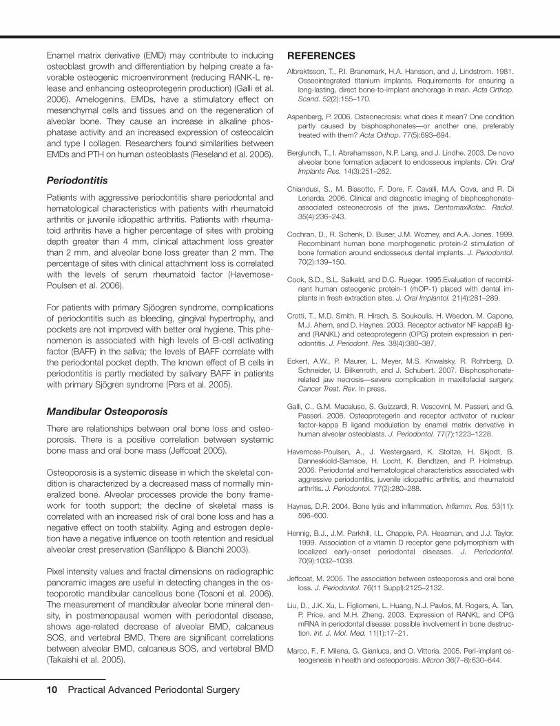
The pterygopalatine division courses through the pterygopala-tine fossa and sends four major branches to the posterior su-perior alveolar, descending palatine, infraorbital, and spheno-palatine. The posterior superior alveolar enters the distal of themaxillary tuberosity and supplies the teeth, gingiva, and max-illary sinus. The descending palatine exits through the greaterpalatine foramen apical to the molars and courses forwardalong the palatal vault (Fig. 3.2), supplying glands and mucosauntil it reaches the incisive canal, where it anastomoses withthe incisive branch of the sphenopalatine artery. The infraor-bital passes medial through the floor of the orbit with branchesto the mid and anterior incisive areas, the maxillary sinus, andthe lacrimal duct and then exits through the infraorbital notchto the face. The sphenopalatine rises to the roof of the noseand then distributes forward and down to the lateral nasal wall(common with the medial wall of maxillary sinus) and mediallyalong the vomer groove to the incisive canal, where it de-
13
Chapter 3 The Wound-Healing Process
Albert Price, DMD, MS
Fig. 3.1 Distribution of the maxillary artery. (From Woodburne 1965.)
scends to merge with the incisive branch of the greater pala-tine (Woodburne 1965) (see Fig. 3.1).
ALVEOLAR AND BASAL BONE
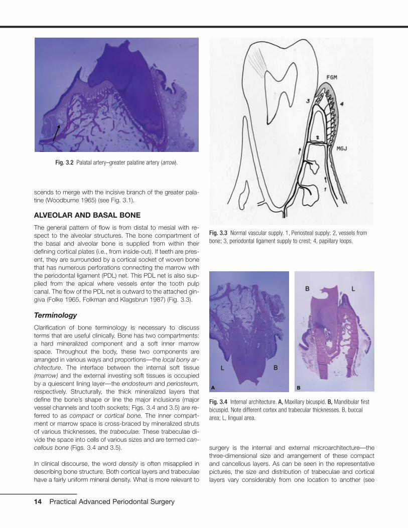
The general pattern of flow is from distal to mesial with re-spect to the alveolar structures. The bone compartment ofthe basal and alveolar bone is supplied from within theirdefining cortical plates (i.e., from inside-out). If teeth are pres-ent, they are surrounded by a cortical socket of woven bonethat has numerous perforations connecting the marrow withthe periodontal ligament (PDL) net. This PDL net is also sup-plied from the apical where vessels enter the tooth pulpcanal. The flow of the PDL net is outward to the attached gin-giva (Folke 1965, Folkman and Klagsbrun 1987) (Fig. 3.3).
Terminology
Clarification of bone terminology is necessary to discussterms that are useful clinically. Bone has two compartments:a hard mineralized component and a soft inner marrowspace. Throughout the body, these two components arearranged in various ways and proportions—the local bony ar-chitecture. The interface between the internal soft tissue(marrow) and the external investing soft tissues is occupiedby a quiescent lining layer—the endosteum and periosteum,respectively. Structurally, the thick mineralized layers thatdefine the bone’s shape or line the major inclusions (majorvessel channels and tooth sockets; Figs. 3.4 and 3.5) are re-ferred to as compact or cortical bone. The inner compart-ment or marrow space is cross-braced by mineralized strutsof various thicknesses, the trabeculae. These trabeculae di-vide the space into cells of various sizes and are termed can-cellous bone (Figs. 3.4 and 3.5).
In clinical discourse, the word density is often misapplied indescribing bone structure. Both cortical layers and trabeculaehave a fairly uniform mineral density. What is more relevant to
surgery is the internal and external microarchitecture—thethree-dimensional size and arrangement of these compactand cancellous layers. As can be seen in the representativepictures, the size and distribution of trabeculae and corticallayers vary considerably from one location to another (see
14 Practical Advanced Periodontal Surgery
Fig. 3.2 Palatal artery–greater palatine artery (arrow).
Fig. 3.3 Normal vascular supply. 1, Periosteal supply; 2, vessels frombone; 3, periodontal ligament supply to crest; 4, papillary loops.
Fig. 3.4 Internal architecture. A, Maxillary bicuspid. B, Mandibular firstbicuspid. Note different cortex and trabecular thicknesses. B, buccalarea; L, lingual area.

Figs. 3.4 and 3.5). Cortical layers form the outer borders of thefacial and lingual (palatal) plates of the alveolar and basal boneand the lining of the tooth sockets. Cortex is also present atthe borders of the sinus, nose, and vascular channels—the in-ferior alveolar canal, mental foramen, and incisal canal.
Cortical by definition is “without marrow” but “not without avasculature.” These cortical parts of bone are densely calci-fied collagen layers with self-entrapped osteoblasts (osteo-cytes). These enclosed cells maintain contact with each otherand outside nutritional sources through tiny cytoplasmic ex-tensions within channels called canaliculi. There is a criticaldistance from the vasculature to these canals beyond whichthese cells cannot survive (0.1 to 0.2 mm) (Ham 1965). Evenin the cortical bone, small vascular channels perfuse thestructure (Fig. 3.6). Marrow of cancellous bone can be fibrousor fatty, or a combination, and it has more varied vascularsupply as well as cells with regenerative potential.
The spatial position of teeth in the alveolar housing requiresconsideration because it influences the vascular distributionin the adjacent bone mass. In most cases, the teeth are settoward the buccal limits of their confining bone “house,”commonly called the alveolar bone. This results in a verythin, entirely cortical bone plate on the buccal (Fig. 3.6),while the lingual limits can have a thicker compact surfacewith marrow between it and the alveolus as the structure ex-tends apically. The vascular supply to these thin buccalplates, because there is no marrow supply, is limited to dif-fusion from the buccal through the investing mucosal tissuesand internally from the PDL. (Note in Fig. 3.6 that resorptionis proceeding on the PDL side of the thin buccal plate, whichhas had a full-thickness flap reflected.) In interproximal, lin-gual, and furcal areas, the internal marrow supply supple-ments the PDL.
The Maxilla and Mandible
The maxilla and mandible have major differences in their bonyarchitecture, and this is reflected in the pattern of their vascu-lar supply. The maxilla is of lighter construction and interfaceswith other cranial structures of intramembranous origin. Themandible is heavy, more self-contained, and closer to the en-dochondral embryology of the other long bones.
In the maxilla, as noted, the major supply of blood comesfrom the pterygopalatine division of the maxillary artery. In thecase of the maxillary sinus, the blood flow is from the supe-rior alveolar, infraorbital, and sphenopalatine arteries. A majorarterial branch is occasionally found running anterior to pos-terior along the lateral wall of the sinus. This artery may fallwithin the marrow of the antral wall if the wall is thick enough,
Wound-Healing Process 15
Fig. 3.6 Small perfused vessels in very thin buccal plate (arrow). Note:Bone cells cannot live more than 0.1 to 0.2 mm from the blood supply.
Fig. 3.5 Internal architecture of furcation area of first molars.A, Maxillary first molar. B, Mandibular first molar. Note differences incortex and trabecular dimensions at maxillary versus mandibular sites.B, buccal area; L, lingual area.
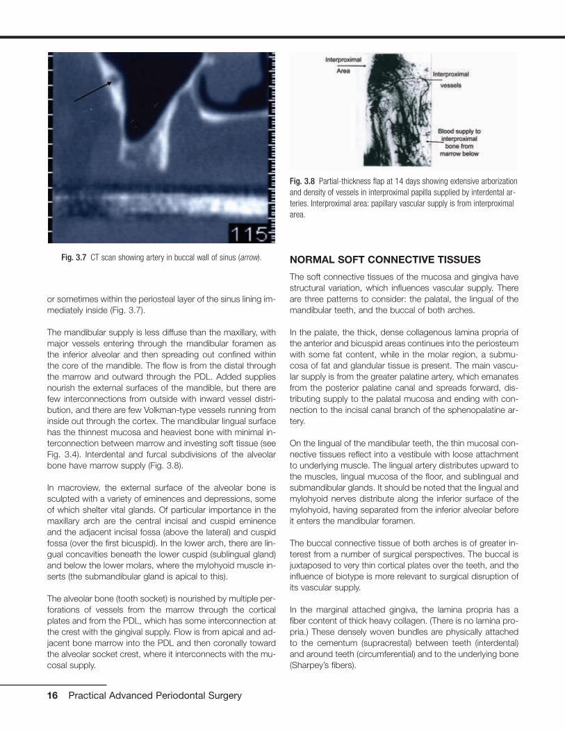
or sometimes within the periosteal layer of the sinus lining im-mediately inside (Fig. 3.7).
The mandibular supply is less diffuse than the maxillary, withmajor vessels entering through the mandibular foramen asthe inferior alveolar and then spreading out confined withinthe core of the mandible. The flow is from the distal throughthe marrow and outward through the PDL. Added suppliesnourish the external surfaces of the mandible, but there arefew interconnections from outside with inward vessel distri-bution, and there are few Volkman-type vessels running frominside out through the cortex. The mandibular lingual surfacehas the thinnest mucosa and heaviest bone with minimal in-terconnection between marrow and investing soft tissue (seeFig. 3.4). Interdental and furcal subdivisions of the alveolarbone have marrow supply (Fig. 3.8).
In macroview, the external surface of the alveolar bone issculpted with a variety of eminences and depressions, someof which shelter vital glands. Of particular importance in themaxillary arch are the central incisal and cuspid eminenceand the adjacent incisal fossa (above the lateral) and cuspidfossa (over the first bicuspid). In the lower arch, there are lin-gual concavities beneath the lower cuspid (sublingual gland)and below the lower molars, where the mylohyoid muscle in-serts (the submandibular gland is apical to this).
The alveolar bone (tooth socket) is nourished by multiple per-forations of vessels from the marrow through the corticalplates and from the PDL, which has some interconnection atthe crest with the gingival supply. Flow is from apical and ad-jacent bone marrow into the PDL and then coronally towardthe alveolar socket crest, where it interconnects with the mu-cosal supply.
NORMAL SOFT CONNECTIVE TISSUES
The soft connective tissues of the mucosa and gingiva havestructural variation, which influences vascular supply. Thereare three patterns to consider: the palatal, the lingual of themandibular teeth, and the buccal of both arches.
In the palate, the thick, dense collagenous lamina propria ofthe anterior and bicuspid areas continues into the periosteumwith some fat content, while in the molar region, a submu-cosa of fat and glandular tissue is present. The main vascu-lar supply is from the greater palatine artery, which emanatesfrom the posterior palatine canal and spreads forward, dis-tributing supply to the palatal mucosa and ending with con-nection to the incisal canal branch of the sphenopalatine ar-tery.
On the lingual of the mandibular teeth, the thin mucosal con-nective tissues reflect into a vestibule with loose attachmentto underlying muscle. The lingual artery distributes upward tothe muscles, lingual mucosa of the floor, and sublingual andsubmandibular glands. It should be noted that the lingual andmylohyoid nerves distribute along the inferior surface of themylohyoid, having separated from the inferior alveolar beforeit enters the mandibular foramen.
The buccal connective tissue of both arches is of greater in-terest from a number of surgical perspectives. The buccal isjuxtaposed to very thin cortical plates over the teeth, and theinfluence of biotype is more relevant to surgical disruption ofits vascular supply.
In the marginal attached gingiva, the lamina propria has afiber content of thick heavy collagen. (There is no lamina pro-pria.) These densely woven bundles are physically attachedto the cementum (supracrestal) between teeth (interdental)and around teeth (circumferential) and to the underlying bone(Sharpey’s fibers).
16 Practical Advanced Periodontal Surgery
Fig. 3.7 CT scan showing artery in buccal wall of sinus (arrow).
Fig. 3.8 Partial-thickness flap at 14 days showing extensive arborizationand density of vessels in interproximal papilla supplied by interdental ar-teries. Interproximal area: papillary vascular supply is from interproximalarea.

This heavy fiber connection continues to the mucogingivaljunction and is the “attachment” of the attached gingiva (Fig.3.9). The dense, compact structural arrangement of the fiberdistribution perpendicular to the bone surface is interlacedwith a fine capillary net fed by both the PDL net and a subep-ithelial plexus of vessels that flows just beneath the rete pegformation. The third source of vascular supply is from larger
vessels that branch from the mucosal corium just below themucogingival junction (Fig. 3.10). The general pattern of flowis from the distal at an angle from apical to coronal throughthe mucogingival junction.
The arrangement of fibers in the periosteal layer of the mu-cosa is quite different. At the transition marked clinically by themucogingival junction, the dense, tight attachment of fibersthrough the periosteum of the attached gingiva changesabruptly to a parallel layering of fibers over the periosteal layerwith very little attachment to the bone (Fig. 3.11).
Between the periosteum and the lamina propria of the mu-cosal epithelium is a less dense submucosa of elastin, fibril-lar collagen, and muscle fibers. The areolar structure of thissubmucosa allows for a larger vascular net in the mucosa in-cluding arterioles and large veins (Fig. 3.12).
Scattered through this matrix are active mesenchymal and in-flammatory cells, which maintain and remodel the matrix; pe-
Wound-Healing Process 17
Fig. 3.10 Full-thickness flap at 7 days. Periosteal zone of connectivetissue was stripped from inner surface of flap. Note the differences invessel size and complexity of mucosa versus gingival (view from buccal).GA, gingival area; MGJ, mucogingival junction; MA, mucosal area. Thelarger vessels are visible.
Fig. 3.11 Periosteum in mucosal zone: fibers run parallel to surface.
Fig. 3.12 Large arteries and veins in mucosal area.
Fig. 3.9 Periosteum in attached gingival zone: dense Sharpey’s fiberinsertion.

riosteal cells, which have bone-repair potential; and the cells,platelets, and soluble biomolecules contained within the vas-cular channels. (It is at the mucogingival junction that com-paction of the gingival collagen fiber density reaches its mostextreme and constricts the corium blood supply most se-verely) (Figs. 3.13 and 3.14).
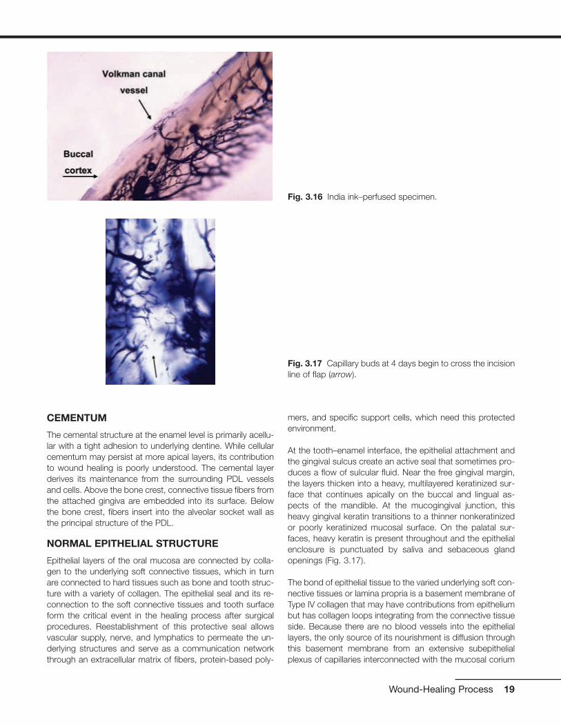
The periosteum of the external bone surfaces receives nour-ishment through diffusion from connective tissue above it andseldom from true Volkman canal vessel penetrations from in-side the bone outward through the cortical layers (Figs. 3.3,3.15, and 3.16).
As previously noted, the marginal gingiva has several sourcesof blood flow: the PDL, the interdental, the subepithelial, andthe deeper mucosal flow. The latter two sources, especially thecorium or central flow, become constricted at the mucogingivaljunction, which is compressed like an hourglass from buccal tolingual and is further limited by the dense fiber arrangement inthe gingival tissues (see Figs. 3.3 and 3.9). The degree of con-finement is influenced by the biotype. In rhesus monkeys, itwas observed that when the biotype was thin, there was usu-ally only one artery (45 to 55 µm) through the mucogingivaljunction, while in thicker tissue, the arteries were slightly smaller(35 to 45 µm) but there were more of them (Price 1974).
18 Practical Advanced Periodontal Surgery
Fig. 3.13 Mucogingival junction (MGJ) transition from denseto areolar base tissue.
Fig. 3.14 Mucogingival junction (MGJ).
Fig. 3.15 A, Partial-thickness flap. B, Full-thickness flap. Novessels are exiting bone surface.
CEMENTUM
The cemental structure at the enamel level is primarily acellu-lar with a tight adhesion to underlying dentine. While cellularcementum may persist at more apical layers, its contributionto wound healing is poorly understood. The cemental layerderives its maintenance from the surrounding PDL vesselsand cells. Above the bone crest, connective tissue fibers fromthe attached gingiva are embedded into its surface. Belowthe bone crest, fibers insert into the alveolar socket wall asthe principal structure of the PDL.
NORMAL EPITHELIAL STRUCTURE
Epithelial layers of the oral mucosa are connected by colla-gen to the underlying soft connective tissues, which in turnare connected to hard tissues such as bone and tooth struc-ture with a variety of collagen. The epithelial seal and its re-connection to the soft connective tissues and tooth surfaceform the critical event in the healing process after surgicalprocedures. Reestablishment of this protective seal allowsvascular supply, nerve, and lymphatics to permeate the un-derlying structures and serve as a communication networkthrough an extracellular matrix of fibers, protein-based poly-
mers, and specific support cells, which need this protectedenvironment.
At the tooth–enamel interface, the epithelial attachment andthe gingival sulcus create an active seal that sometimes pro-duces a flow of sulcular fluid. Near the free gingival margin,the layers thicken into a heavy, multilayered keratinized sur-face that continues apically on the buccal and lingual as-pects of the mandible. At the mucogingival junction, thisheavy gingival keratin transitions to a thinner nonkeratinizedor poorly keratinized mucosal surface. On the palatal sur-faces, heavy keratin is present throughout and the epithelialenclosure is punctuated by saliva and sebaceous glandopenings (Fig. 3.17).
The bond of epithelial tissue to the varied underlying soft con-nective tissues or lamina propria is a basement membrane ofType IV collagen that may have contributions from epitheliumbut has collagen loops integrating from the connective tissueside. Because there are no blood vessels into the epitheliallayers, the only source of its nourishment is diffusion throughthis basement membrane from an extensive subepithelialplexus of capillaries interconnected with the mucosal corium
Wound-Healing Process 19
Fig. 3.16 India ink–perfused specimen.
Fig. 3.17 Capillary buds at 4 days begin to cross the incisionline of flap (arrow).

at several levels and at the alveolar socket crest with the vas-cular net of the PDL (Figs. 3.3, 3.17, 3.18, and 3.19).
THE WOUND-HEALING PROCESS PER SE
While the wound-healing process in periodontal surgery in-volves mechanisms common to other areas of the body,most notably, the skin, it has some unique features related tothe presence of a tooth. Rates of activity may vary (turnoverrate of alveolar bone versus basal bone) (Garant 2003), andmicroenvironments of local tissue architecture (attached gin-giva, PDL, mucogingival junction, and so on) may influencethe local microvasculature (Price 1974), but the general pat-tern and sequence of healing activities seem to be the same.Because vascular disruption and regeneration are central towound-healing response, it is convenient to view the twocompartments—soft tissues of gingiva/mucosa and hard tis-sues of tooth/bone—separately. As noted in the precedinganatomy review, while there is some interconnection, thehard tissues receive their supply from inside the bone, andthe soft tissues are supplied from outside the bone.
Closure of a soft tissue wound requires epithelialization, fibro-plasia, and angiogenesis, which occur simultaneously but atdifferent rates and stages of healing. Immediately following anincision deep enough to injure the vasculature, platelets (nor-mal range, 150,000 to 400,000/µL, produced by megakary-ocytes in the bone marrow; Ganong 2001, Schmeyer 2001)are exposed to adjacent collagen and begin to adhere. Thisadherence activates extrusion of granules from the platelets,some of which facilitate the transformation of prothrombin tothrombin, which in turn catalyzes soluble fibrinogen to fibrin.
A fibrin net enmeshed with increasing numbers of platelets,red blood cells, circulating polymorphonucleocytes (PMNs),and macrophages contributes to an initial vascular plug orclot, which slows and stops further bleeding. This temporaryor provisional matrix of cells and fibers releases a variety ofchemical attractants and activators (platelet-derived growthfactor [PDGF], vascular endothelial growth factor [VEGF], andtransforming growth factor [TGF] ß) that stimulate the sur-rounding tissue layers and attract even more PMNs andmacrophages from adjacent leaky venules (6 to 10 hours)(Clark 1996). The noncollagenous protein vitronectin, whichis produced by the liver and circulates in the blood serum,possibly acts as a preliminary substrate for migration of theseearly scavenger cells.
Epithelial cells adjacent to the wound edge respond almostimmediately and begin to migrate across the fibrin surface atrates estimated to be 0.5 mm/day. Within 24 hours, epithelialcells adjacent to this, formerly quiescent, begin to proliferate.Meanwhile, the PMNs in the clot begin to phagocytize bacte-ria, necrotic cells, and platelet debris. Resident macrophagesare joined by those migrating out of the leaking vascularchannels and begin to cleanse the wound of debris and bro-ken degenerating PMNs (PMNs survive 24 to 48 hours)(Bartold 1998, Davis 2000, Garant 2003). At the same time,the macrophages release additional growth factors and cel-lular fibronectin, which, with fibrin, become the attachmentsurface for the subsequent wave of migrating cells—the fi-broblasts, endothelial, and epithelial cells.
The term fibroplasia embodies a sequence of shifting priori-ties during which the fibroblast undergoes several changes in
20 Practical Advanced Periodontal Surgery
Fig. 3.19 Twenty-one–day regeneration of papillary loops: Atthis stage, web has thinned out to single long arching capil-laries connected to base by newly forming subpapillaryplexus.
Fig. 3.18 Fourteen days: regeneration of papillary loops. Atthis stage, newly forming connective tissue papillas are sup-plied by a web of vessels.

phenotypic expression. Clark in 1993 and later in 1996 de-scribed several phases: proliferation, migration, production,and transformation to myofibroblast. The proliferation phaseof fibroblasts occurs in the first 2 to 3 days in the margins ofthe wound. These early fibroblasts are said to have vit-ronectin adhesion capability but not fibronectin connectivityon their membrane surfaces. By days 4 to 7, the fibroblastsswitch to a migrating mode and, aided by their adhesion tofibronectin (two sources: local made by macrophages andanother in circulating plasma) and fibrin, invade the space for-merly occupied by the provisional matrix. As they migrate, thefibroblasts deposit collagen and matrix molecules externally(Bartold 1998, Clark 1993, Kurkinen 1980, Welsch 1990).
Angiogenesis parallels this activity with venular endotheliumproliferating in place for the first few days. The cell layersthicken and the outer layer lifts off, forming a space or lumenas the endothelial intracellular cementation breaks down, en-abling a migratory phase. This activity at the ends of cut ves-sels results in an abundance of cord-like arrays and loopsthat by days 4 to 5 have started to enter the clot space (seeFig. 3.17). These early activities are characterized clinically bya red, granular appearance consistent with this rapid vesseland matrix formation—the granulation tissue.
This granulation tissue is gradually replaced by mature fibers,matrix, and reconnected blood vessels—the organizationphase. Extracellular fluids that had previously leaked out intothe wound area during this migratory phase are resorbed, andclinical swelling begins to resolve at 5 to 6 days. At 7 days,vessels can be found to be patent but leaky, while at 14 days,the leakage has stopped (see Fig. 3.18). New circulation ismature by 21 to 28 days with gradual reduction of vesselnumber in favor of regular distribution and flow in the newconnective tissue (Price 1974) (compare Figs. 3.18 and 3.19).
Collagens and various noncollagen molecules (hyaluron,elastin, fibronectin, and so on) are expressed into the matrix(days 4 to 10), and this in turn provides further traction andvolume for migrating cells (Bartold 1998). The migrating fi-broblasts now assume a fourth form (myofibroblast), whichhas characteristics of muscle. The combination of tractionand continued migration pulls the edges of the wound inwardin the phenomenon of early wound contraction, which, withcontinued epithelial migration, closes the wound surface(Clark 1996, Kurkinen 1980, Welsch 1990). The maturingcollagen/noncollagen matrix is then in a phase where bonehealing might begin (10 to 14 days). Vascular penetration inbone chambers can move at different rates in cancellousbone (0.5 mm/day) versus cortical bone (0.05 mm/day)(Rhinelander 1974a, 1974b). Osteoblasts differentiate frommesenchymal cells present within the marrow and periocytesaround blood vessel walls, while osteoclasts are said to mi-grate from the blood vascular system (possible monocytelineage?) (Ganong 2001, Schmaier 2003). Vascular ingrowthalways precedes osteogenesis (Albrektsson 1980a, 1980b).
With the increasingly stable and maturing matrix formation,osteoblasts and osteoclasts can begin early cleanup andbone matrix deposition. Injured bone areas show osteoclastactivity as early as 7 days, which persists at 14 days and isfollowed at 21 days by osteoblastic presence (Pfeiffer 1965).
The epithelium is mostly complete with layers by 21 to 28days. Soft connective tissue including its vasculature contin-ues to mature for 35 to 42 days (5 to 6 weeks) (see Figs. 3.17through 3.19). Bone healing continues for 6 to 8 weeks, atwhich time a rapidly formed woven bone is present. This isgradually remodeled in a slower process, which creates ma-ture lamellar bone. All of these events assume a stable envi-ronment with no reinjury or mobility of the site.
Intrabony healing, which is necessary after the controlledtrauma of implant replacement and bone grafting, is a specialsituation that places increased demands on basic processes.The initial rates of activity remain the same but there are sev-eral secondary responses that need to occur for integrationof either implant or graft particle. Additionally, in the case ofthe graft particle, it is desirable that the graft itself eventuallybe replaced by new bone (Branemark 1985).
The final result can be either regeneration (complete restitu-tion of structure and function) or repair (fibrous replacementwith creation of a seal).
REFERENCESAlbrektsson, T. 1980a. The healing of autogenous bone graft after vary-
ing degrees of surgical trauma. J. Bone Joint Surg. 62B:403–410.
Albrektsson, T. 1980b. Repair of bone graft. A vital microscopic and his-tological investigation in the rabbit. Scand. J. Plast. Reconstr. Surg.14:1–12.
Bartold, P.M., et al. 1998. Biology of the Periodontal Connective Tissues.Quintessence Books, Chicago.
Branemark, P.I., et al. 1985. Tissue-Integrated Prostheses. Quintes-sence, Chicago.
Clark, R.A.F. 1993. Regulation of fibroplasia in cutaneous wound repair.Am J. Med. Sci. 306(1):42–48.
Clark, R.A.F. 1996. The Molecular and Cellular Biology of Wound Repair,2nd ed. Kluwer Academic Publishers, Plenum Press, New York.
Folke, L.E.A., et al. 1965. Periodontal microcirculation as revealed byplastic microspheres. J. Periosteal. Res. 2:53–63.
Folkman, J., and M. Klagsbrun. 1987. Angiogenic factors. Science23:442–448.
Ganong, W.F. 2001. Review of Medical Physiology, 20th ed. LangeMedical Books/McGraw-Hill, New York.
Garant, P.R. 2003. Oral Cells and Tissues. Quintessence, Chicago.
Ham, A.W. 1965. Histology, 5th ed. J.B. Lippincott, Philadelphia.
Wound-Healing Process 21
Kurkinen, M., et al. 1980. Sequential appearance of fibronectin and colla-gen in experimental granulation tissue. Lab. Invest. 43:47–51, 1980.
Pfeiffer, J.S. 1965. The growth of gingival tissue over denuded bone. J.Periosteal. 34:10–16, 1965.
Price, A.M. 1974. Comparison of the microvascular disruption and re-generation following full, partial, and modified partial thickness flapsin the alveolar mucosa of Macaca mulatta. DScD thesis, BostonUniversity, Boston.
Rhinelander, F.W. 1974a. The normal circulation of bone and its responseto surgical intervention. J. Biomed. Mater. Res. 8:87.
Rhinelander, F.W. 1974b. Tibial blood supply in relation to fracture heal-ing. Clin. Orthop. 105:34.
Schmaier, A.H., et al. 2003. Hematology for the Medical Student.Lippincott Williams and Wilkins, Philadelphia.
Woodburne, A.M. 1965. Essential of Human Anatomy, 3rd ed. OxfordUniversity Press, New York.
22 Practical Advanced Periodontal Surgery
HISTORY
The innovative combination of selective alveolar periodontaldecortication surgery and augmentation grafting with ortho-dontic treatment results in an acceleration of orthodontictreatment, enhanced stability of orthodontic results, andlong-term improvement of the periodontium (Wilcko 2003).The purposes of this section are to describe the PeriodontallyAccelerated Osteogenic Orthodontics technique and to ex-plain how and why this advanced periodontal surgical tech-nique contributes to orthodontic treatment.
Decortication or corticotomy means simply the intentionalcutting or injury of cortical bone. While the bony jaws arecomposed of both cortical and medullary bone in variouscombinations depending on site and patient demographics,the periodontal surgery of interest in contemporary selectivealveolar decortication involves only surgical injury of alveolarcortical bone.
The application of corticotomy surgery to correct malocclu-sion was first described in 1892 by L. C. Bryan, but it wasHeinrich Köle in 1959 who reintroduced alveolar corticotomyto resolve malocclusion (Köle 1959). He combined interden-tal alveolar corticotomy surgery with a through-and-throughosteotomy apical to the teeth. Generson et al. in 1978 offereda modification of the Köle protocol and eliminated the subapi-cal osteotomy portion of the surgery.
In 2001, Wilcko et al. described selective alveolar decortica-tion with augmentation grafting combined with orthodontictreatment. They patented and trademarked their technique asPeriodontally Accelerated Osteogenic Orthodontics (PAOO).Full-thickness labial and lingual alveolar flaps were laid adja-cent to the teeth intended for movement, and selective decor-tication surgery was performed. Given that the surgery wasdone only in the area of desired tooth movement, it was thethickness of cortical bone that dictated where and how thecortical bone was injured. The depth of the decortication cutsbarely penetrated into medullary bone and bleeding was pro-moted; care was taken not to injure any tooth or encroach onthe periodontal ligament. An allograft of resorbable graftingmaterial plus antibiotic was applied directly over the bleeding
bone, and the surgical site was closed using Gore-Tex suturematerial. A frequently used grafting mixture was equal por-tions of demineralized freeze-dried bone (DFDBA) and bovinebone (Osteograf/N-300 or Bio-Oss) wetted with clindamycinphosphate (Cleocin) solution.
Wilcko et al. observed rapid orthodontics following PAOOand active treatment times of 6 to 8 months were common.They questioned Köle’s precept of “bony block” movementand offered an alternative hypothesis that rapid tooth move-ment resulted from marked but transient decalcification-recalcification of the alveolus. Frost, an orthopedic surgeon,had described a direct correlation between degree and prox-imity of bone trauma and intensity of physiological healing re-sponse, which he coined Regional Acceleratory Phenomena,or RAP (Frost 1983), and the decalcification-recalcificationdescribed by Wilcko et al. (2001, 2003) was consistent withRAP.
INDICATIONS
• Increased alveolar volume and enhanced periodontium(i.e., correction of dehiscences and fenestrations)
• Accelerated treatment (i.e., 3 to 4 times more rapid activeorthodontic treatment)
• Greater stability of clinical outcomes and less relapse
• Enhanced scope of malocclusion treatment (i.e., avoidingorthognathic surgery and extractions in selected cases)
• Enhancement of patient’s profile when indicated
• Rapid recovery of impacted teeth (i.e., canines)
The initial decortication protocol used by the Wilcko brothersdid not include augmentation alveolar grafting. ComputedTomography (CT) scans were taken on the first series of pa-tients to compare pretreatment status with immediate postorthodontics and at least 1-year retention conditions. The CTscans of the alveolus immediately after braces were removedshowed a paucity of alveolar bone in the areas where decor-tication surgery was performed. However, the retention im-ages demonstrated that a minimally adequate amount of
23
Chapter 4 The Contribution of Periodontics to Orthodontic Therapy
Donald J. Ferguson, DMD, MSD, M. Thomas Wilcko, DMD,
William M. Wilcko, DMD, MS, and M. Gabriela Marquez, DMD, MSD
Periodontally Accelerated Osteogenic Orthodontics (PAOO)
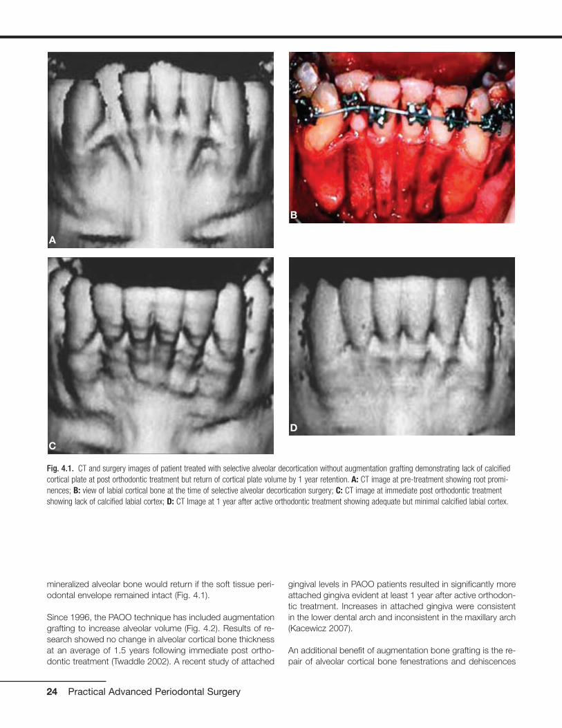
mineralized alveolar bone would return if the soft tissue peri-odontal envelope remained intact (Fig. 4.1).
Since 1996, the PAOO technique has included augmentationgrafting to increase alveolar volume (Fig. 4.2). Results of re-search showed no change in alveolar cortical bone thicknessat an average of 1.5 years following immediate post ortho-dontic treatment (Twaddle 2002). A recent study of attached
gingival levels in PAOO patients resulted in significantly moreattached gingiva evident at least 1 year after active orthodon-tic treatment. Increases in attached gingiva were consistentin the lower dental arch and inconsistent in the maxillary arch(Kacewicz 2007).
An additional benefit of augmentation bone grafting is the re-pair of alveolar cortical bone fenestrations and dehiscences
24 Practical Advanced Periodontal Surgery
Fig. 4.1. CT and surgery images of patient treated with selective alveolar decortication without augmentation grafting demonstrating lack of calcifiedcortical plate at post orthodontic treatment but return of cortical plate volume by 1 year retention. A: CT image at pre-treatment showing root promi-nences; B: view of labial cortical bone at the time of selective alveolar decortication surgery; C: CT image at immediate post orthodontic treatmentshowing lack of calcified labial cortex; D: CT Image at 1 year after active orthodontic treatment showing adequate but minimal calcified labial cortex.
A
B
C
D
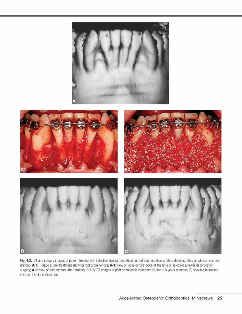
Accelerated Osteogenic Orthodontics, Miniscrews 25
Fig. 4.2. CT and surgery images of patient treated with selective alveolar decortication and augmentation grafting demonstrating ample cortices postgrafting. A: CT image at pre-treatment showing root prominences; A-1: view of labial cortical bone at the time of selective alveolar decorticationsurgery; A-2: view of surgery area after grafting; B & C: CT images at post orthodontic treatment (B) and 2.5 years retention (C) showing increasedvolume of labial cortical bone.
A
B C
A1 A2

(Fig. 4.3). The grafting procedure is done without membranesbecause full-thickness flaps are used followed by primary clo-sure in a healthy periodontium. Under these circumstances,migration of the epithelial attachment is not likely to occur, andthe intact periosteum serves as a natural “membrane.”
PAOO has contributed greater stability of orthodontic clinicaloutcomes and less relapse. Stability of orthodontic clinicaloutcomes was analyzed by Nazarov in 2003 using theObjective Grading System (OGS) sanctioned by theAmerican Board of Orthodontics (ABO). While no differenceswere observed in nonextraction therapies at immediate posttreatment between PAOO and non-PAOO groups, three ofthe nine OGS variables (alignment, marginal ridges, and totalscore) were significantly better in the PAOO group at reten-tion. O’Hara (2005) compared nonextraction orthodontictreatment of moderate malocclusions and found no differ-ences in the OGS alignment variables at post treatment. Butat retention, alignment had improved in the PAOO group,whereas in the two non-PAOO groups, fixed and removableappliance retention, alignment had relapsed. In summary, im-mediate post orthodontic treatment results following nonex-traction therapy are statistically the same with or without
PAOO. However, during retention, the clinical outcomes ofPAOO patients improved and did not demonstrate relapse.
PAOO increases the scope of orthodontic tooth movementand the positions of the teeth after decortication and aug-mentation grafting are stable long-term. Sarver and Proffit(2005) offered guidelines as to the limits of central incisortooth movement in the adult patient with orthodontic treat-ment alone. Ferguson et al. (2006) suggested that these lim-its can be expanded 2-fold to 3-fold in all dimensions exceptretraction following PAOO (see Fig. 4.4) and that the stabilityof these positions is probably due to loss of tissue memoryfrom high turnover of the periodontium as well as increasedthickness of the alveolar cortices from the augmentationgrafting. Rothe et al. (2006) found that patients with thinnermandibular cortices were at increased risk for having dentalrelapse—hence the necessity for osseous grafting during thePAOO procedure.
Periodontics, through PAOO therapy, contributes to ortho-dontic treatment by reducing active orthodontic treatmenttime. Claims of rapid orthodontic treatment times were firstvalidated in research by Hajji in 2000; average active ortho-
26 Practical Advanced Periodontal Surgery
Fig. 4.3. Augmentation alveolar grafting repairs bony dehiscences and fenestrations. A: evidence of bony discrepancies after full thickness flap, B:decortication prior to grafting with dehiscences and fenestrations outlined; C-D: absence of dehiscences and fenestrations 7.5 years post PAOOdecortication and grafting.
BA
DC
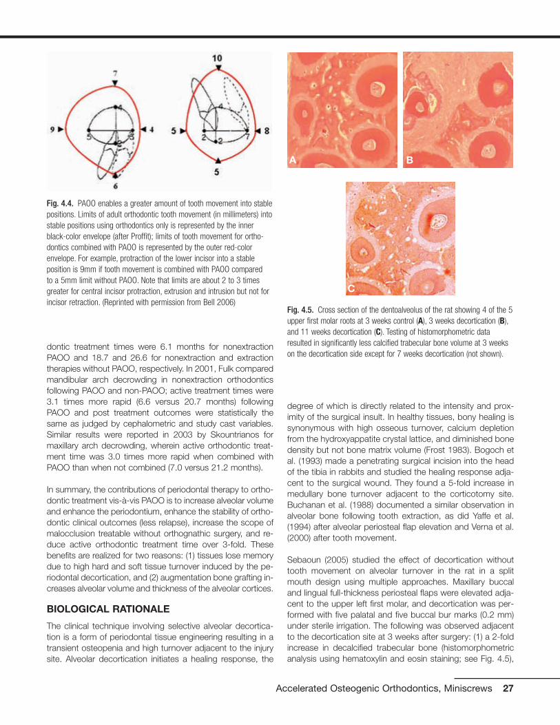
dontic treatment times were 6.1 months for nonextractionPAOO and 18.7 and 26.6 for nonextraction and extractiontherapies without PAOO, respectively. In 2001, Fulk comparedmandibular arch decrowding in nonextraction orthodonticsfollowing PAOO and non-PAOO; active treatment times were3.1 times more rapid (6.6 versus 20.7 months) followingPAOO and post treatment outcomes were statistically thesame as judged by cephalometric and study cast variables.Similar results were reported in 2003 by Skountrianos formaxillary arch decrowding, wherein active orthodontic treat-ment time was 3.0 times more rapid when combined withPAOO than when not combined (7.0 versus 21.2 months).
In summary, the contributions of periodontal therapy to ortho-dontic treatment vis-à-vis PAOO is to increase alveolar volumeand enhance the periodontium, enhance the stability of ortho-dontic clinical outcomes (less relapse), increase the scope ofmalocclusion treatable without orthognathic surgery, and re-duce active orthodontic treatment time over 3-fold. Thesebenefits are realized for two reasons: (1) tissues lose memorydue to high hard and soft tissue turnover induced by the pe-riodontal decortication, and (2) augmentation bone grafting in-creases alveolar volume and thickness of the alveolar cortices.
BIOLOGICAL RATIONALE
The clinical technique involving selective alveolar decortica-tion is a form of periodontal tissue engineering resulting in atransient osteopenia and high turnover adjacent to the injurysite. Alveolar decortication initiates a healing response, the
degree of which is directly related to the intensity and prox-imity of the surgical insult. In healthy tissues, bony healing issynonymous with high osseous turnover, calcium depletionfrom the hydroxyappatite crystal lattice, and diminished bonedensity but not bone matrix volume (Frost 1983). Bogoch etal. (1993) made a penetrating surgical incision into the headof the tibia in rabbits and studied the healing response adja-cent to the surgical wound. They found a 5-fold increase inmedullary bone turnover adjacent to the corticotomy site.Buchanan et al. (1988) documented a similar observation inalveolar bone following tooth extraction, as did Yaffe et al.(1994) after alveolar periosteal flap elevation and Verna et al.(2000) after tooth movement.
Sebaoun (2005) studied the effect of decortication withouttooth movement on alveolar turnover in the rat in a splitmouth design using multiple approaches. Maxillary buccaland lingual full-thickness periosteal flaps were elevated adja-cent to the upper left first molar, and decortication was per-formed with five palatal and five buccal bur marks (0.2 mm)under sterile irrigation. The following was observed adjacentto the decortication site at 3 weeks after surgery: (1) a 2-foldincrease in decalcified trabecular bone (histomorphometricanalysis using hematoxylin and eosin staining; see Fig. 4.5),
Accelerated Osteogenic Orthodontics, Miniscrews 27
Fig. 4.4. PAOO enables a greater amount of tooth movement into stablepositions. Limits of adult orthodontic tooth movement (in millimeters) intostable positions using orthodontics only is represented by the innerblack-color envelope (after Proffit); limits of tooth movement for ortho-dontics combined with PAOO is represented by the outer red-colorenvelope. For example, protraction of the lower incisor into a stableposition is 9mm if tooth movement is combined with PAOO compared to a 5mm limit without PAOO. Note that limits are about 2 to 3 timesgreater for central incisor protraction, extrusion and intrusion but not forincisor retraction. (Reprinted with permission from Bell 2006)
Fig. 4.5. Cross section of the dentoalveolus of the rat showing 4 of the 5upper first molar roots at 3 weeks control (A), 3 weeks decortication (B),and 11 weeks decortication (C). Testing of histomorphometric dataresulted in significantly less calcified trabecular bone volume at 3 weekson the decortication side except for 7 weeks decortication (not shown).
A B
C

(2) a 1.5-fold increase in new trabecular bone formation (vitalstaining ad libitum), (3) a 4-fold increase is osteoclast count(osteoclast count after TRAP staining), and (4) a 2-fold in-crease in lamina dura apposition (vital stain injection series;see Fig. 4.6). These findings collectively indicate high tissueturnover immediately adjacent to the decortication site.
Pham-Nguyen (2006) studied the three-dimensional volumeof periodontal tissues surrounding the upper first molar inthe rat model following buccal and lingual selective decorti-cation. Using micro-CT technology, a significant decrease inalveolar mineralization was evident by 7 days post decorti-cation (Fig. 4.7).
Conceptually, increased tissue turnover (osteopenia) is a con-dition that favors rapid tooth movement. This tenet wasdemonstrated by Verna et al. (2000) using a rat model bymoving teeth after pharmacologically inducing high and lowbone turnover. They showed significantly greater tooth move-ment in the high turnover group compared with normal andlow bone turnover groups. In our laboratory rat studies(Pham-Nguyen 2006, Sebaoun 2005), surgical injury to thealveolus induced a dramatic increase in tissue turnover thatwas expressed both spatially and temporally. The effect ofalveolar decortication was localized to the area immediatelyadjacent to the injury. It is obvious that considerable medul-lary bone demineralization occurs immediately adjacent tothe decortication site. Although induced osteopenia is a tran-sient condition in the functionally normal alveolus, it was sur-mised that tooth movement perpetuates the decalicified con-dition of the trabecular bone (Fig. 4.8).
PERIODONTALLY ACCELERATEDOSTEOGENIC ORTHODONTICS IN THETREATMENT OF CROWDING
Using the PAOO technique, cases of moderate dental archcrowding are routinely completed in 4 to 6 months instead of
18 to 24 months of active orthodontic treatment, and the re-sults have been shown to be remarkably stable (Figs. 4.9 and4.10).
RAPID RECOVERY OF IMPACTED TEETH
Recovery of impacted teeth typically prolongs active ortho-dontic treatment time. Impacted tooth recovery combinedwith selective alveolar periodontal decortication surgery ac-celerates the recovery and reduces orthodontic treatmenttime. The purpose of this section is to describe an advancedperiodontal surgical technique of recovering impacted cus-pids that features the following: (1) complete exposure of theclinical crown, (2) clearing a path for recovery by way of alve-olar ostectomy, and (3) selective alveolar decortication or in-tramarrow penetrations surrounding the impacted tooth root.
With the exception of the third molars, the maxillary caninesare the most frequently encountered impaction, with an inci-dence of approximately 2% according to Ericson and Kurol(1987). The incidence of maxillary canine impaction is 3 timesgreater in females than in males and is often associated withmissing or peg-shaped laterals (Bec et al. 1981, Peck et al.1994). Maxillary permanent canines are impacted palatally
28 Practical Advanced Periodontal Surgery
Fig. 4.6. Amount of apposition of the lamina dura is shown in crosssection of the dentoalveolus of the rat at 4 weeks, the end of the firstseries of vital stain injections. Total width of apposition as revealed bythe three stains together was statistically greater on the decorticationside (A, 0.051mm) at 3 weeks than the control side (B, 0.037mm) at 3 weeks.
Fig. 4.7. Micro-CT analysis of osteopenia at 7 days following selectivealveolar decortication showing gross specimen #602 (A), control side (B)and decortication side (C).On the decortication side, osteopenia wasdemonstrated as the bone volume (BV) to total volume (TV) ratio de-creased to 45% (note the wide spaces surrounding the roots, C) com-pared to 57% on the control side (B). (Pham-Nguyen K, et al. 2006)
AA
B
B C
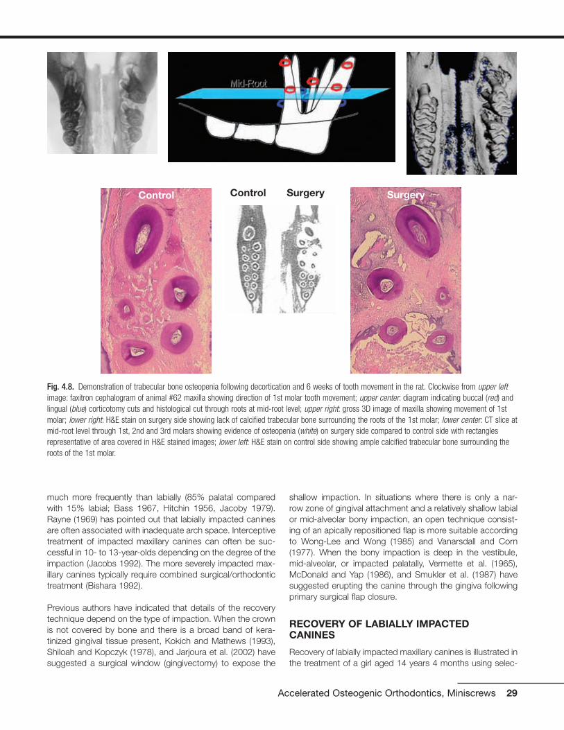
much more frequently than labially (85% palatal comparedwith 15% labial; Bass 1967, Hitchin 1956, Jacoby 1979).Rayne (1969) has pointed out that labially impacted caninesare often associated with inadequate arch space. Interceptivetreatment of impacted maxillary canines can often be suc-cessful in 10- to 13-year-olds depending on the degree of theimpaction (Jacobs 1992). The more severely impacted max-illary canines typically require combined surgical/orthodontictreatment (Bishara 1992).
Previous authors have indicated that details of the recoverytechnique depend on the type of impaction. When the crownis not covered by bone and there is a broad band of kera-tinized gingival tissue present, Kokich and Mathews (1993),Shiloah and Kopczyk (1978), and Jarjoura et al. (2002) havesuggested a surgical window (gingivectomy) to expose the
shallow impaction. In situations where there is only a nar-row zone of gingival attachment and a relatively shallow labialor mid-alveolar bony impaction, an open technique consist-ing of an apically repositioned flap is more suitable accordingto Wong-Lee and Wong (1985) and Vanarsdall and Corn(1977). When the bony impaction is deep in the vestibule,mid-alveolar, or impacted palatally, Vermette et al. (1965),McDonald and Yap (1986), and Smukler et al. (1987) havesuggested erupting the canine through the gingiva followingprimary surgical flap closure.
RECOVERY OF LABIALLY IMPACTEDCANINES
Recovery of labially impacted maxillary canines is illustrated inthe treatment of a girl aged 14 years 4 months using selec-
Accelerated Osteogenic Orthodontics, Miniscrews 29
Fig. 4.8. Demonstration of trabecular bone osteopenia following decortication and 6 weeks of tooth movement in the rat. Clockwise from upper leftimage: faxitron cephalogram of animal #62 maxilla showing direction of 1st molar tooth movement; upper center: diagram indicating buccal (red) andlingual (blue) corticotomy cuts and histological cut through roots at mid-root level; upper right: gross 3D image of maxilla showing movement of 1stmolar; lower right: H&E stain on surgery side showing lack of calcified trabecular bone surrounding the roots of the 1st molar; lower center: CT slice atmid-root level through 1st, 2nd and 3rd molars showing evidence of osteopenia (white) on surgery side compared to control side with rectanglesrepresentative of area covered in H&E stained images; lower left: H&E stain on control side showing ample calcified trabecular bone surrounding theroots of the 1st molar.
Control Control Surgery Surgery
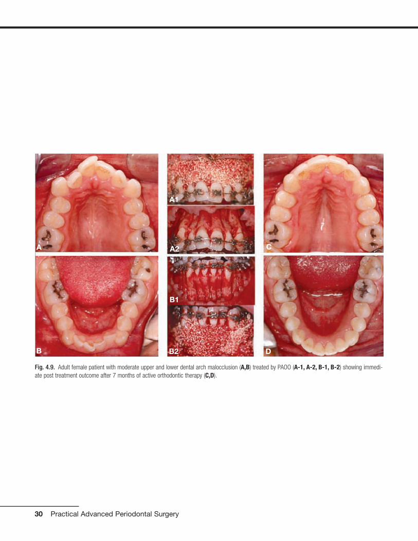
30 Practical Advanced Periodontal Surgery
Fig. 4.9. Adult female patient with moderate upper and lower dental arch malocclusion (A,B) treated by PAOO (A-1, A-2, B-1, B-2) showing immedi-ate post treatment outcome after 7 months of active orthodontic therapy (C,D).
A
B
C
D
A2
A1
B1
B2

Accelerated Osteogenic Orthodontics, Miniscrews 31
Fig. 4.10. Retention outcome at 2 years (A,B) and 9 years (C,D) after the completion of PAOO treatment. Improvement during retention and long termstability are likely due to high tissue turnover induced by decortication and increase in cortical bone thickness.
A B
C D

tive decortication technique (Figs. 4.11, 4.12, and 4.13). Afull-thickness labial flap, using a sulcular incision with verticalreleasing incisions mesial to the first premolars, was reflectedto reveal upper cuspid crowns labial to the upper permanentlateral incisors. No lingual flap was reflected. The upper pri-mary canines were extracted, and the soft tissue follicle andthin layer of bone surrounding cuspid crowns were removed.A path (trough) was cleared for the forced eruptions by re-moving the facial cortical plate between the cuspid crownsand extraction sockets including the facial plates over thesockets. In addition, numerous intramarrow penetrationswere made to stimulate alveolar bone turnover and to induce
32 Practical Advanced Periodontal Surgery
Fig. 4.11. Labially impacted maxillary canines showing pre-surgery (A),partial exposure of canine crowns after full-thickness flap (B), and boneremoval to expose canine crowns completely, intramarrow penetrations,and creation of a path by removing facial cortical plates of extractionsocket (C).
Fig. 4.12. Treatment for labially impacted maxillary canines showingviews of different cases at the time of surgery (A, D, G, B, E, H) and at10 weeks post surgery (C, F, I). An orthodontic bracket was placed in an optimal position on the exposed right canine (A) but on the lingualsurface of the crown on the left canine (G). At the time of soft tissueclosure, a vertical incision was made in the flap allowing exposure of theright canine bracket (B) but not the left canine (H) before suturing theflap to the original position (E). The canines were beginning to moverapidly by 10 weeks after the canine recovery surgery (C, F, I).
A
A
B
C
B
C
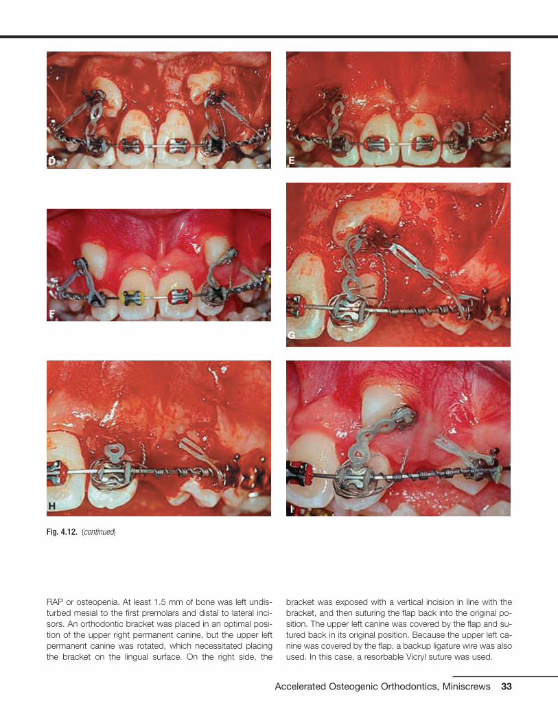
RAP or osteopenia. At least 1.5 mm of bone was left undis-turbed mesial to the first premolars and distal to lateral inci-sors. An orthodontic bracket was placed in an optimal posi-tion of the upper right permanent canine, but the upper leftpermanent canine was rotated, which necessitated placingthe bracket on the lingual surface. On the right side, the
bracket was exposed with a vertical incision in line with thebracket, and then suturing the flap back into the original po-sition. The upper left canine was covered by the flap and su-tured back in its original position. Because the upper left ca-nine was covered by the flap, a backup ligature wire was alsoused. In this case, a resorbable Vicryl suture was used.
Accelerated Osteogenic Orthodontics, Miniscrews 33
Fig. 4.12. (continued)
D
G
F
I
E
H

34 Practical Advanced Periodontal Surgery
Fig. 4.13. Results of treatment for labially impacted maxillary canines showing pre-treatment malocclusion (A-C) and clinical outcome 4 months afterremoval of orthodontic appliances (D-F). Active treatment time to recover the canines was 5 months and 2 weeks.
A B
C D
E F
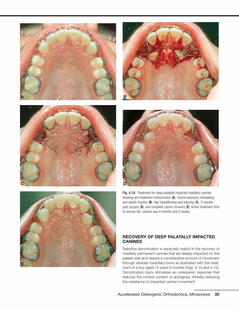
RECOVERY OF DEEP PALATALLY IMPACTEDCANINES
Selective decortication is especially helpful in the recovery ofmaxillary permanent canines that are deeply impacted on thepalatal side and require a considerable amount of movementthrough alveolar medullary bone as illustrated with the treat-ment of a boy aged 14 years 6 months (Figs. 4.14 and 4.15).Decortication injury stimulates an osteopenic response thatreduces the mineral content of spongiosa, thereby reducingthe resistance to impacted canine movement.
Accelerated Osteogenic Orthodontics, Miniscrews 35
Fig. 4.14. Treatment for deep palatally impacted maxillary caninesshowing pre-treatment malocclusion (A), canine exposure, bracketingand elastic traction (B), flap repositioning and suturing (C), 3 monthspost surgery (D), and complete canine recovery (E). Active treatment timeto recover the canines was 6 months and 0 weeks.
A
C D
E
B

36 Practical Advanced Periodontal Surgery
Fig. 4.15. Treatment for deep palatally impacted maxillary canine showing pretreatment malocclusion (A) and radiograph (H), flap with verticalreleasing incision showing labial cortical plate (B), ostectomy removal of labial cortical and medullary bone to clear a movement path and exposecanine crown, and labial intramarrow penetrations (C), bracket placement and application of elastic traction (D), immediate postsurgical flap suturing(E) and radiograph (F) with radiograph (I), and 9 days after orthodontic appliance removal (G) with radiograph (K). Active treatment time to recover thecanine was 6 months 0 weeks.
A
B
F
C
D
E

Accelerated Osteogenic Orthodontics, Miniscrews 37
Fig. 4.15. (continued)
G
H
I
J
K

Both facial and lingual full-thickness flaps are used with dis-tal vertical releasing incisions for access to deep palatally im-pacted canines. Preference is given to placement of ortho-dontic brackets into an optimal positioned on the labialsurface of the canine crown for control and efficiency. Whendirect access to the labial surface and optimal bracket place-ment is not possible, the surface of choice for bracket place-ment is the distolabial surface of impacted canines. An ostec-tomy is required between the first premolar and the lateralincisor to gain access to the appropriate impacted caninesurface. The ostectomy not only permits optimal bracketplacement but also creates a space for the elastic chain fromthe bracket on the impacted canine to the brackets on theadjacent teeth already well positioned in the dental arch.Moreover, bone needs to be removed when crowns are ex-posed because the follicle surrounding the enamel is elimi-nated and bone resorption secondary to follicular activity islost. The ostectomy should eliminate all bone in the move-ment path of the crown during impacted canine recovery, butit is important to leave about 1.5 mm of bone on the proximalsurfaces of the adjacent teeth. Intramarrow penetrations arealso performed, especially in the bone that lies between theimpacted tooth and its eventual position in the dental arch.Intramarrow penetrations over the root prominence of the im-pacted tooth facing in the direction of movement stimulatemedullary osteopenia and reduce tooth movement resist-ance. After the bracket has been placed, a ligature wire is se-cured to the bracket of the impacted tooth as backup in theevent the elastic chain was to break. A bracket with a post orpower arm pointing apically is preferred to reduce the likeli-hood of the chain elastic slipping off the bracket. The full-thickness flaps are returned to their original positioning andsutured. In the case demonstrating recovery of deep palatallyimpacted canines (Figs. 4.14 and 4.15), nonresorbable 5-0 green braided polyester suture material was used, butthe type of suture material used is usually not relevant. Sutureremoval, when necessary, is recommended anytime after 1week of postoperative healing.
PERIODONTAL SURGICAL PROCEDURES FORORTHODONTIC ACCESS, AESTHETICS, ANDSTABILITY
Excessive gingival attachment serves no useful purpose be-fore, during, or after orthodontic treatment. There are severalreasons for excessive gingival attachment. Gingival excess canresult from systemic medications that produce undesirableside effects of gingival hyperplasia such as dilantin, nifedipine,and amlodipine or gingival swelling such as cyclosporine; thick,fibrotic gingival overgrowth can produce tooth movementand/or malocclusion. Excessive gingival attachment can resultfrom familial hereditary gingival hyperplasia or, more commonly,by delayed passive eruption of teeth (Fig. 4.16).
Surgical removal of gingiva is called gingivectomy, and gin-givoplasty refers to recontouring the gingival architecture
and/or changing the gingival shape. These simple periodon-tal surgical procedures can contribute meaningfully to ortho-dontic access, aesthetics, and treatment outcome stability.The fundamental reasons for gingivoplasty procedures are toprovide more optimal clinical crown appearances or accessand to change gingival shape. According to Sarver (2004),exposure of the clinical crowns that contribute most to theaesthetic smile, the maxillary central incisors, should be ap-proximately 80% width compared with height. Moreover, thegingival architecture for the anterior teeth should have certaincharacteristics. The gingival shape of the mandibular incisorsand the maxillary laterals should exhibit a symmetrical half-oval or half-circular shape, and the maxillary centrals and ca-nines should exhibit a gingival shape that is more elliptical.Thus, the gingival zenith (the most apical point of the gingivaltissue) should be located distal to the longitudinal axis of themaxillary centrals and canines, and the gingival zenith of themaxillary laterals and mandibular incisors should coincidewith their longitudinal axis (Fig. 4.17).
Excessive gingival attachment often makes optimal ortho-dontic bracket placement difficult. When the patient is readyfor orthodontic treatment with fixed appliances but access tothe clinical crown precludes optimal bracket position place-ment, a gingivoplasty procedure can be used to establish amore favorable crown-to-crestal height relationship by re-moval of excess gingiva. This is a frequent finding in youngpatients ready for orthodontic treatment in the late mixed orearly permanent dentition (Fig. 4.18).
Removal of excessive gingival tissues is useful during thecourse of orthodontic treatment to facilitate good oral hy-giene and to help in the consolidation of the dental arch
38 Practical Advanced Periodontal Surgery
Fig. 4.16. Delayed passive eruption of teeth can lead to excessive gingi-val attachment: normal attachment (left), moderate excess attachment(center), and severe excess attachment (right). Note that the tip of theperiodontal probe rests at the gingival crest demonstrating that clinicalcrown length deceases as gingiva excess increases.

Accelerated Osteogenic Orthodontics, Miniscrews 39
Fig. 4.17. Optimal maxillary incisor exposure for esthetics is 1.0 to 0.8crown height-to-width ratio and ideally, gingival zenith or most apicalpoint of the gingival tissue is distal to longitudinal crown axis. (After:Sarver MS, AJODO, 126:749-753, 2004.)
Fig. 4.18. Increasing access to upper incisor clinical crowns for bracketing on an 11 year old orthodontic patient: pre-treatment (A), 15 days postgingivoplasty (B), and post incisor bracketing (C).
A B
C

spacing and orthodontic detailing and finishing. Moreover,gingivoplasty at least 2 weeks before removal of fixed ortho-dontic appliances allows sufficient gingival healing to enablethe fabrication of an overlay, Essix type of orthodontic retainerthat is well adapted to the gingival contours (Fig. 4.19).
Post orthodontic gingivoplasty can contribute to both smileaesthetics and stability of treatment outcomes (Fig. 4.20).The supracrestal gingival fibers have been identified as con-
tributing to orthodontic relapse, especially rotation relapse,and consequently the procedure called supracrestal fibro-tomy has been recommended (Edwards 1988). Others havesuggested that orthodontic treatment outcome stability ismore likely due to an increase in the elasticity of the wholecompressed gingival tissue (Redlich et al. 1996). In eithercase, gingivoplasty influences the turnover and adaptation ofboth supracrestal and compressed gingival tissues, therebyreducing orthodontic treatment outcome instability.
40 Practical Advanced Periodontal Surgery
Fig. 4.19. Removal of excessive upper anterior gingiva was accom-plished during the course of active orthodontic treatment in a 15 yearold patient: pre-gingivoplasty (A,B), gingivoplasty and frenectomy (C),and 7 days after the gingivoplasty (D) and post orthodontic treatment (E).
AB
C D
E
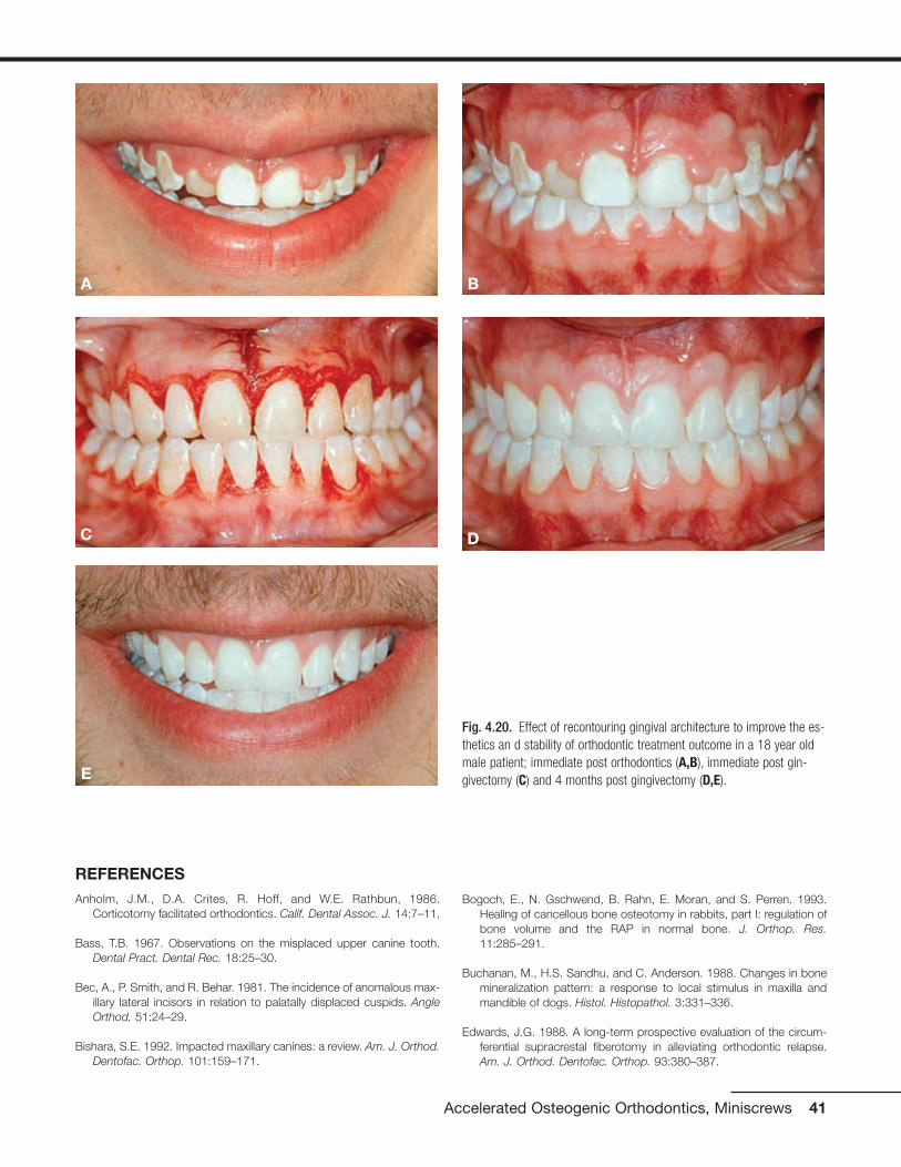
REFERENCES Anholm, J.M., D.A. Crites, R. Hoff, and W.E. Rathbun, 1986.
Corticotomy facilitated orthodontics. Calif. Dental Assoc. J. 14:7–11.
Bass, T.B. 1967. Observations on the misplaced upper canine tooth.Dental Pract. Dental Rec. 18:25–30.
Bec, A., P. Smith, and R. Behar. 1981. The incidence of anomalous max-illary lateral incisors in relation to palatally displaced cuspids. AngleOrthod. 51:24–29.
Bishara, S.E. 1992. Impacted maxillary canines: a review. Am. J. Orthod.Dentofac. Orthop. 101:159–171.
Bogoch, E., N. Gschwend, B. Rahn, E. Moran, and S. Perren. 1993.Healing of cancellous bone osteotomy in rabbits, part I: regulation ofbone volume and the RAP in normal bone. J. Orthop. Res.11:285–291.
Buchanan, M., H.S. Sandhu, and C. Anderson. 1988. Changes in bonemineralization pattern: a response to local stimulus in maxilla andmandible of dogs. Histol. Histopathol. 3:331–336.
Edwards, J.G. 1988. A long-term prospective evaluation of the circum-ferential supracrestal fiberotomy in alleviating orthodontic relapse.Am. J. Orthod. Dentofac. Orthop. 93:380–387.
Accelerated Osteogenic Orthodontics, Miniscrews 41
Fig. 4.20. Effect of recontouring gingival architecture to improve the es-thetics an d stability of orthodontic treatment outcome in a 18 year oldmale patient; immediate post orthodontics (A,B), immediate post gin-givectomy (C) and 4 months post gingivectomy (D,E).E
A B
C D

Ericson, S., and J. Kurol. 1987. Radiographic examination of ectopicallyerupting maxillary canines. Am. J. Orthod. Dentofac. Orthop.91:483–492.
Ferguson, D.J., W.M. Wilcko, and M.T. Wilcko. 2006. Selective alveolardecortication for rapid surgical-orthodontic resolution of skeletal mal-occlusion. In W.E. Bell and C. Guerrero, editors. DistractionOsteogenesis of the Facial Skeleton. BC Decker, Hamilton, Ontario,Canada.
Frost, H.A. 1983. The regional acceleratory phenomena: a review. HenryFord Hosp. Med. J. 31:3–9.
Fulk, L.A. 2001. Lower arch decrowding comparing corticotomy-facilitated, midline distraction and conventional orthodontic tech-niques. Master’s degree thesis in orthodontics, Saint Louis University.
Gantes, B., E. Rathburn, and M. Anholm. 1990. Effects on the periodon-tium following corticotomy-facilitated orthodontics. J. Periodontol.61:234–238.
Generson, R.M., J.M. Porter, A. Zell, and G.T. Stratigos. 1978.Combined surgical and orthodontic management of anterior openbite using corticotomy. J. Oral Surg. 36:216–219.
Hajji, S.S. 2000. The influence of accelerated osteogenic response onmandibular decrowding. Master’s degree thesis in orthodontics, SaintLouis University.
Hitchin, A.D. 1956. The impacted maxillary canine. Br. Dental J.100:1–14.
Jacobs, S.G. 1992. Reducing the incidence of palatally impacted maxil-lary canines: a useful preventative interceptive orthodontic procedure:case report. Austral. Dental J. 37: 6–11.
Jacoby, H. 1979. The “Batista spring” system for impacted teeth. Am. J.Orthod. 75:43–51.
Jarjoura, K., P. Krespo, and J.B. Fine. 2002. Maxillary canine impactions:orthodontic and surgical management. Comp. Cont. Educ. Dent.23:23–38.
Kokich, V., and D.P. Mathews. 1993. Surgical and orthodontic manage-ment of impacted teeth. Dent. Clin. North Am. 37:181–204.
Köle, H. 1959. Surgical operations on the alveolar ridge to correct oc-clusal abnormalities. Oral Surg. Oral Med. Oral Pathol. 12:515–529.
Machado, I.M., D.J. Ferguson, W.M. Wilcko, and M.T. Wilcko. 2002.Reabsorcion radicular despues del tratamiento ortodoncico con o sincorticotomia alveolar. Rev. Venezuelana Orthod. 19:647–653.
McDonald, F., and W.L. Yap. 1986. Surgical exposure and application ofdirect traction of unerupted teeth. Am. J. Orthod. 89: 331–340.
Nazarov, A.D. 2003. Improved retention following corticotomy using BOObjective Grading System. Master’s degree thesis in orthodontics,Saint Louis University.
O’Hara, P. 2005. Orthodontic treatment and retention outcomes withand without PAOO and fixed retainers. Master’s thesis in orthodon-tics, Boston University.
Peck, S., and M. Kataja. 1994. The palatally displaced canine as a den-tal anomaly of genetic origin. Angle Orthod. 64:249–256.
Pham-Nguyen, K. 2006. Micro-CT analysis of osteopenia following se-lective alveolar decortication and tooth movement. Master’s degreethesis in orthodontics, Boston University.
Rayne, J. 1969. The unerupted maxillary canine. Dental Pract. DentalRec. 19:194–204.
Redlich, M., E. Rahamim, A. Gaft, and S. Shoshan. 1996. The responseof supra-alveolar gingival collagen to orthodontic rotation movementsin dogs. Am. J. Orthod. Dentofac. Orthop. 110:247–255.
Rothe, L.E. 2006. Trabecular and cortical bone as risk factors for ortho-dontic relapse. Am. J. Orthod. Dentofac. Orthop. 129:316.
Rothe, L.E., A.M. Bollen, R.M. Little, S.W. Herring, J.B. Chaison, C.S.K.Chen, and L.G. Hollender. 2006. Trabecular and cortical bone as riskfactors for orthodontic relapse. Am. J. Orthod. Dentofac. Orthop.130:476–484.
Sarver, D.M., and W.R. Proffit. 2005. Special considerations in diagnosisand treatment planning. In T.M. Graber, R.L. Vanarsdall, and K.W.L.Vig, editors. Orthodontics: Current Principles and Techniques.Elsevier, St. Louis, p. 15.
Sarver, D.M. 2004. Principles of cosmetic dentistry in orthodontics: part1. Shape and proportionality of anterior teeth. Am. J. Orthod.Dentofac. Orthop. 126:749–753.
Sebaoun, J.D. 2005. Trabecular bone modeling and RAP following se-lective alveolar decortication. Master’s degree thesis in orthodontics,Boston University.
Shiloah, J., and R. Kopczyk. 1978. Mucogingival considerations in sur-gical exposure of maxillary canines: report of case. ASDC J. Dent.Child. 45: 79–81.
Skountrianos, H.S. 2003. Maxillary arch decrowding and stability withand without corticotomy-facilitated orthodontics. Master’s degreethesis in Orthodontics, Saint Louis University.
Smukler, H., G. Castellucci, and H.M. Goldman. 1987. Surgical manage-ment of palatally impacted cuspids. Comp. Cont. Educ. Dent.8:10–77.
Suya, H. 1991. Corticotomy in orthodontics. In E. Hösl and A. Baldauf,editors. Mechanical and Biological Basics in Orthodontic Therapy.Hüthig, Heidelberg, pp. 207–226.
Twaddle, B.A., D.J., Ferguson, W.M., Wilcko, M.T., Wilcko, and C.-Y. Lin.2002. Dento-alveolar bone density changes following accelerated or-thodontics. J. Dental Res. 80:301.
Vanarsdall, R.L., and H. Corn. 1977. Soft tissue management of labiallypositioned unerupted teeth. Am. J. Orthod. 72:53–66.
Vermette, M.E., V.G. Kokich, and D.B. Kennedy. 1995. Uncovering labi-ally impacted teeth: apically positioned flap and closed eruption tech-nique, Angle Orthod. 65:23–32.
Verna, C., M. Dalstra, and B. Melsen. 2000. The rate and type of ortho-dontic tooth movement is influenced by bone turnover in the ratmodel. Eur. J. Orthod. 22:343–352.
Wilcko, W.M., D.J. Ferguson, J.E. Bouquot, and M.T. Wilcko. 2003.Rapid orthodontic decrowding with alveolar augmentation: case re-port. World J. Orthod. 4:197–205.
42 Practical Advanced Periodontal Surgery

HISTORY
Implants for use as orthodontic anchorage devices have re-cently become very popular because most are easy to placeand remove and inexpensive and can be directly or indirectlyloaded with biomechanical forces immediately after place-ment. Unlike the osseointegrated implants used for pros-thetic restorations, implants for orthodontic anchorage relyon mechanical retention and depend on the thickness of cor-tical bone for stability (Huja 2005). This screw-in type of im-plant is known by many names such as temporary anchor-age devise (TAD), mini-implant, microscrew, or miniscrew.
Implants for orthodontic anchorage were first described inthe literature in 1945 by Gainsforth and Higley and were usedto retract the canine tooth in the dog model. In 1983,Creekmore and Eklund reported placement of a screw devicein the anterior nasal spine area for use in the intrusion ofupper permanent incisors in the treatment of adult deep bitemalocclusion. Kanomi in 1997 provided detailed descriptionof loading microimplants less than 1.0 mm in diameter follow-ing 3 months of osseous integration. Since 2000, the dentalliterature has been inundated with articles describing new de-signs and the use of immediate-load implants as anchoragedevices for the treatment of malocclusion. In general, theyhave proved successful for intrusion and extrusion, protrac-tion, and retraction of individual teeth as well as groups ofteeth.
Miniscrew implants are the smallest among all fixed implants;they are the most versatile and adaptable for clinical use andare categorized as either non–bracket-head or bracket-head.The most commonly used implant for orthodontic anchorageis self-drilling with a nonbracket head. These self-drilling andself-tapping (a different cutting point for self-drilling) miniscrewshave emerged during the past 6 years as the most popular andfrequently used type of orthodontic anchorage implant, andthis type of miniscrew will be the focus of this chapter.
Desirable features of a miniscrew include the screw threads,soft tissue sleeve or transmucosal collar, platform, and head(Fig. 4.21). The screw thread portion interfaces with corticalbone; the transmucosal collar interfaces with the soft tissuesof the periosteum, either keratinized or nonkeratinized; the
platform or soft tissue stop protects the soft tissue from theattachments that connect the miniscrew to the orthodonticappliance and also decreases the likelihood of tissue over-growth around the screw head; and the head provides themeans (often a round hole) for connecting the miniscrew tothe orthodontic appliance as well as the screwdriver slots forapplying self-drilling and self-tapping pressure.
INDICATIONS
• When “absolute” orthodontic anchorage is needed
• Adequate cortical bone thickness and quality
• Healthy soft and hard tissues of the periodontium
Miniscrews are now considered a reliable anchorage devicefor orthodontic treatment. Since Food and Drug Admini-stration approval in 1999, these devices have broadened thescope of treatment possibilities not only in orthodontics but inperiodontics and prosthodontics as well. Without the use of
Accelerated Osteogenic Orthodontics, Miniscrews 43
Wilcko, W.M., M.T. Wilcko, J.E. Bouquot, and D.J. Ferguson. 2001.Rapid orthodontics with alveolar reshaping: two case reports of de-crowding. Int. J. Periodont. Restor. Dent. 21:9–19.
Wong-Lee, T.H., and F.C. Wong. 1985. Maintain an ideal tooth-gingivalrelationship when exposing and aligning an impacted tooth. Br. J.Orthod. 12:189–192.
Yaffe, A., N. Fine, I. Alt, and I. Binderman. 1994. Regional acceleratedphenomena in the mandible following mucoperiosteal flap surgery. J.Periodontol. 65:79–83.
Miniscrew Implants for Orthodontic Anchorage
Fig. 4.21. Desirable features of self-drilling miniscrews include thescrew threads, soft tissue sleeve or transmucosal collar, platform andhead. Left: Self-drilling miniscrew with non-bracket head (Courtesy ofKLS Corporation). Middle and Right: Self-drilling, self-tapping SpiderScrew K1 short transmucosal collar (middle) and long neck (right) withbracket like head (Courtesy of Ortho Technology, Inc. exclusive distributorof Spider Screw products for HDC Italy.)
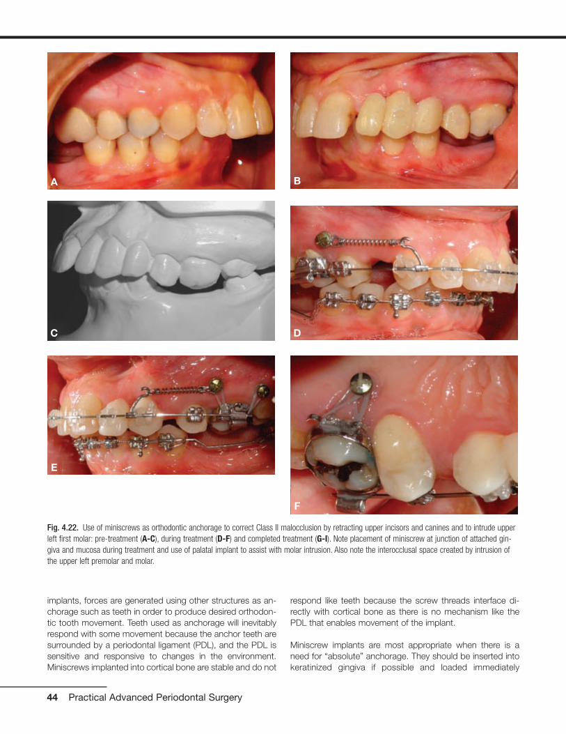
implants, forces are generated using other structures as an-chorage such as teeth in order to produce desired orthodon-tic tooth movement. Teeth used as anchorage will inevitablyrespond with some movement because the anchor teeth aresurrounded by a periodontal ligament (PDL), and the PDL issensitive and responsive to changes in the environment.Miniscrews implanted into cortical bone are stable and do not
respond like teeth because the screw threads interface di-rectly with cortical bone as there is no mechanism like thePDL that enables movement of the implant.
Miniscrew implants are most appropriate when there is aneed for “absolute” anchorage. They should be inserted intokeratinized gingiva if possible and loaded immediately
44 Practical Advanced Periodontal Surgery
Fig. 4.22. Use of miniscrews as orthodontic anchorage to correct Class II malocclusion by retracting upper incisors and canines and to intrude upperleft first molar: pre-treatment (A-C), during treatment (D-F) and completed treatment (G-I). Note placement of miniscrew at junction of attached gin-giva and mucosa during treatment and use of palatal implant to assist with molar intrusion. Also note the interocclusal space created by intrusion ofthe upper left premolar and molar.
A B
C D
E
F

(Melsen and Costa 2000) or within the first 2 weeks of heal-ing (Liou et al. 2004). These devices are effective as anchor-age for moving teeth in three spatial planes such as retract-ing the upper incisors and canines in the treatment of ClassII malocclusion following first premolar extraction or intrusionof molars (Fig. 4.22) or protracting posterior teeth to closespace (Fig. 4.23).
Miniscrew stability depends on cortical bone thicknessbecause spongy bone contributes virtually nothing to im-plant stability (Melsen 2005). Alveolar bone is composed ofcompact (cortical) and spongy (trabecular or medullary)bone. Medullary bone is a highly adaptable tissue, and it re-sponds quickly to changes in the environment with model-ing or surface change, whereas cortical bone responds
Accelerated Osteogenic Orthodontics, Miniscrews 45
Fig. 4.22. (continued)
Fig. 4.23. Two uses of miniscrew as orthodontic anchorage to protract posterior teeth: Left: Miniscrew used to secure NiTi closed coil spring formolar protraction and elastic chain for premolar protraction. Right: Open coil spring placed mesial to molar allows protraction of the premolar only;steel ligature tie from miniscrew to molar prevents distal molar movement. Note the less desirable placement of the miniscrew below mucogingivaljunction (left) and more desirable placement of the miniscrew at junction of attached gingiva and mucosa (right).
G
I
H

slowly to stimuli with remodeling or internal change. Bonemodeling is an uncoupled activity of activation (A) followedby formation (F) or resorption (R). Because an activation canlead to either resorption (A-R) or formation (A-F), spongybone very quickly adapts to any stimuli or change in en-vironment. In contrast, compact bone undergoes boneremodeling which is a coupled sequence of activation (A)followed by resorption (R) followed by formation (F) or A-R-F sequence. The A-R-F sequence is otherwise knownas the process of secondary osteon formation: physiologi-cal activation (a stimulus) followed by bone resorption (cut-ting cone) followed by bone formation (filling cone).Remodeling (A-R-F) is a slow process that assures struc-tural integrity of the host skeleton (Roberts et al. 2004). The principal reason for miniscrew implant stability is attrib-uted to the slow bony turnover response of cortical bone(Fig. 4.24).
Miniscrew thread lengths vary from 4 mm to 12 mm withlonger thread lengths recommended for bicortical retention(Freudenthaler et al. 2001). In most circumstances, mini-screw thread length need not exceed the width of monocor-tical thickness. A miniscrew thread length of 6 mm should beadequate and a 4-mm thread length is optimal under mostcircumstances because monocortical alveolar bone thick-ness ranges between 2 and 3.5 mm on the facial or lingualmandible in the areas of the first and second molars(Masumoto et al. 2001) and 2 and 7 mm in the palate
(Bernhart et al. 2000, King et al. 2006). The soft tissue sleevewidth should be at least 2.5 mm, as this is approximately theaverage thickness of keratinized soft tissue of the periodon-tium (Costa et al. 2005). Some manufacturers provide shortand long transmucosal collars to accommodate variations ofsoft tissue thickness.
Some situations contraindicate use of miniscrews, accordingto Park et al. (2003). Miniscrews are contraindicated in thepresence of active infection such as untreated periodontaldisease and when there is inadequate bone quantity such asin severe alveolar bone loss. When bone quality is compro-mised, as in untreated osteoporosis or a history of systemicdrug use to counteract calcium depletion, miniscrews maybe contraindicated. Miniscrews should not be used whenthere is a limitation in blood supply, when patients are inca-pable of following home care instructions, and during themixed dentition if there is risk of permanently damaging toothbuds. The small size of the miniscrews for the most part pre-cludes any permanent tissue damage (Kanomi 1997); rootperforation is unlikely and any minor root damage will healuneventfully (Mah and Bergstrand 2005). No litigation con-cerning miniscrew use has yet been reported; however, caseselection should be carefully considered. An informed con-sent should be presented to the patient, fully explaining thebenefits and risks (including pain, bleeding, inflammation, im-plant fracture and implant mobility, and/or failure) of usingminiscrews.
46 Practical Advanced Periodontal Surgery
Fig. 4.24. Diagrams illustrating the differences in cortical and spongy bone response to a miniscrew. A: Compact or cortical bone undergoes remod-eling, a coupled sequence of activation then resorption then formation (A-R-F), whereas spongy bone undergoes modeling which is activation followedby either resorption or formation (A-R or A-F). B: Miniscrew implanted into slow turnover cortical bone and rapid reacting spongy bone; miniscrew sta-bility comes from cortical bone.
A B

ARMAMENTARIUM
• Self-drilling or self-tapping miniscrews
• Profound topical anesthetic or an injectable anesthetic
• Manual screwdriver or slow-speed handpiece with appro-priate screwdriver attachment
Technique
The overall soft and hard tissue periodontal condition of thepatient should be thoroughly evaluated and healthy beforeminiscrew placement and application of biomechanicalforces. Self-drilling miniscrews are easy to place and can beimplanted under local soft tissue anesthesia or with the useof a topical anesthetic alone (Graham 2006). A profoundtopical anesthetic is preferred because anesthetizing the
teeth alters the patient’s perception of increased resistanceto screwdriver pressure (suggesting contact with a root)and a change in sensitivity from pressure to sharp pain. Ifresistance is encountered during placement, the miniscrewshould be backed away and redirected or removed com-pletely and placed elsewhere. Melsen (2005) suggests atleast 1 month of healing if there is a desire to place a minis-crew at the identical location of a previous miniscrew. Whena miniscrew needs to be relocated immediately, she sug-gests at least a 5-mm distance from the initial implant site.Vital structures such as major blood vessels, nerves, maxil-lary sinus, and tooth roots need to be avoided during im-plant placement. The use of a guide or “jig” and a verticalbitewing as a reference point to determine the location ofinsertion can be useful in miniscrew placement (Figs. 4.25and 4.26).
Accelerated Osteogenic Orthodontics, Miniscrews 47
Fig. 4.25. Example of an implant guide or “jig” fabricated to assist in the placement of a miniscrew implant: Vacuum-type retainer fabricated on studycast incorporating wire adapted approximating the long axis of 1st molar and 2nd premolar (top left); transfer of guide to patient’s mouth (top right);radiographic image of patient with guide seated (bottom left); and transfer of guide back to study cast to mark position of miniscrew placement aftermeasuring distance between wires on the radiograph (bottom right).

Optimal placement of the miniscrew is into attached or kera-tinized gingiva or at the junction of attached gingiva and mu-cosa (Fig. 4.27). Keratinized gingiva is abundant on the hardpalate but usually limited on the buccal or labial alveolus. Anapically directed insertion is suggested when the band of at-tached gingiva is thin or the attached gingiva level is coronalto the mid-root.
Depending on design, some miniscrews require drilling a pilothole using a dental handpiece before insertion. Self-drillingand self-tapping miniscrews are placed without the assis-tance of a preliminary tap-hole and require only a screw-driver to turn the screw. Miniscrews can be inserted using aslow-speed handpiece attachment, but the use of a hand-manipulated screwdriver is more common. Whenever a man-ual screwdriver is used, irrigation is not necessary; however,a slow insertion speed should be used to minimize the heatgenerated in the bone. The type of equipment needed to in-sert the implant device depends on the screw diameter,screw design (cylindrical versus conical), location (palate ver-sus buccal-labial), and recipient’s bone density.
Where the miniscrew is to be inserted should be determinedbased on the biomechanical requirements and type of me-chanics as well as the root proximity. The location of mini-screw placement between the permanent second premolarand first molar at the level between mid-root to apex is fre-quently used in orthodontics because this location typicallyprovides adequate cortical bone thickness (Masumoto 2001)and is both convenient and strategic as a biomechanical an-chorage site. In general, the hard palate provides ample cor-
tical bone thickness, and all soft tissue is keratinized. Alveolarcortical bone is typically thinner in the maxilla than in themandible and thinner in females than in males, and the ca-nine fossa regions can be particularly thin and problematic forminiscrew retention (Costa et al. 2005).
48 Practical Advanced Periodontal Surgery
Fig. 4.26. Example of a guide fabricated with fixed orthodontic appliances in place. An arch wire segment placed in the brackets of the upper secondpremolar and first molar with loop extended toward vestibule (left). A bitewing radiograph shows the position of wire loop relative to the roots of thetwo teeth (right). The clinician will place the miniscrew mesio-apical to the height of the wire loop.
Fig. 4.27. Optimal placement of the miniscrew is into attached gingiva(AG) or at the junction of the mucosa and attached gingiva (MGJ). Theminiscrew should be directed apically during insertion if the band ofattached gingiva is thin.

Clinical success of the miniscrew is determined by implant sta-bility as long as it is being used as an anchorage device. Norandomized clinical trials have yet been published but manycase reports describe miniscrew failure rates (screw loss ormobility) ranging from 3% to 50% (Cheng et al. 2003, Deguchiet al. 2003, Melsen 2005B, Miyawaki et al. 2003). The stabil-ity depends on mechanical retention at the interfaces of thecortical bone and the screw threads; physical factors that in-fluence stability are screw diameter, thickness of cortical bone,and placement orientation (Miyawaki et al. 2003). There is a di-rect relationship between miniscrew diameter and stability butan inverse relationship between miniscrew diameter and easeof placement with screw thread diameters over 2.5 mm. Self-drilling miniscrews with diameters greater than 2.5 mm be-come difficult to place and screws less than 1.0 mm in diam-eter are at risk for implant fracture, increased instability and/orcomplete failure (loss). The optimal range of self-drilling mini-screw diameter is between 1.5 and 2.0 mm. Placement of aminiscrew perpendicular to cortical bone surface is acceptablewhen cortices are at least 2 mm thick, but when cortical boneis thinner, changing the orientation of the screw and insertingin a more apical direction allows greater screw thread to corti-cal bone contact and greater stability. Optimally, the miniscrewshould be placed into keratinized attached gingival or at leastat the boundary between attached gingival and unbound mu-cosal tissue. While some implant systems advocate place-ment in mucosa to favor distance and/or vector of force be-tween the miniscrew and the target teeth, inflammation andsoft tissue overgrowth are often problems. In those caseswhere miniscrew placement in mucosa cannot be avoided, asoft tissue punch prior to insertion is highly recommended toprevent the loose tissue from engaging the threads of thescrew. A postinsertion radiograph should be taken to confirmappropriate location of the miniscrew, and a 1-week follow-upvisit whenever possible is recommended to check for pain,peri-implantation soft tissue inflammation, and stability. Aftertreatment has been completed, removal of the miniscrew doesnot require anesthesia.
COMPLICATIONS
• Miniscrew mobility
• Peri-implantation inflammation
• Soft tissue injury
• Root damage
• Root resorption/bone loss
• Sinus perforation
• Implant fracture
Complications are less likely to occur with self-drilling or self-tapping miniscrews than with immediate load orthodontic an-chorage systems that require soft tissue incisions or surgicalflaps during placement. Complications that may arise during
self-drilling and/or self-tapping miniscrew placement and useinclude the following.
Miniscrew Mobility
Instability occurs when the interface between cortical boneand miniscrew is not sufficient to provide adequate supportfor the implant. The most common scenarios are when corti-cal bone is too thin or when there is sufficient thickness of thealveolar cortex, but soft tissue thickness is excessive, theminiscrew is too short, and screw threads do not sufficientlyimplant into bone. Failing to load the miniscrew within 2weeks of placement promotes epithelial proliferation in the in-terface of the bone and miniscrew and is another reason forexcessive implant mobility. Miniscrews often become loose in patients with compromised bone quality resulting fromsome systemic bone conditions or the therapeutic effects ofosteoporosis/osteopenia treatment. The miniscrew should beadequate if it is stable enough to withstand the loadingforces; however, if mobility is excessive, then the miniscrewshould be removed.
Peri-implantation Inflammation
Placing miniscrews into alveolar mucosa introduces the riskof soft tissue inflammation and overgrowth with the mini-screw head buried and out of reach. The risk of soft tissue in-flammation can be reduced by prescribing and using cloro-hexidine rinses for 7 days starting the day of the miniscrewinsertion into alveolar mucosa. When miniscrews are used,home care instruction should be carefully explained to thepatient and monitored throughout the treatment, especiallywhen miniscrews are placed into nonkeratinized periodontalsoft tissues.
Soft Tissue Injury
Soft tissue injury may result during placement of a miniscrewinto alveolar mucosa if a soft tissue punch is not used beforeinsertion because the loose mucosa easily engages thethreads of the screw. Attachments from the fixed orthodonticappliance to the head of the screw can injure soft tissue; thisproblem can be minimized by using screws designed withsoft tissue stops or platforms.
Root Damage
Minor root damage usually heals with no consequence (Mahand Bergstrand 2005), especially if the damaged PDL areadoes not exceed 2 mm (Andreasen and Kristerson 1981). Ifthe damage is greater than 2 mm, ankylosis and/or external/internal root resorption may result. In these situations de-velop, close radiographic monitoring is recommended.
Root Resorption/Bone Loss
Root resorption can be the result of excessive force, espe-cially during intrusion. Park et al. (2003) used between 200g
Accelerated Osteogenic Orthodontics, Miniscrews 49
and 300g force to intrude posterior teeth without noticeableroot resorption or vitality problems. Melsen et al. (1988) re-ported that following tooth intrusion, periodontal tissue wasrecovered by new attachment only when good hygiene wasenforced. Intrusion under unhealthy conditions can precipi-tate bone loss; therefore, a 3-month recall regimen is recom-mended for all patients undergoing intrusion movement.
Sinus Perforation
Sinus perforation can be easily avoided by close inspectionof the patient’s radiographs. Pneumatization of the sinus canincrease the likelihood of perforation. If the communicationdoes not exceed 2 mm, no further action needs to be taken.
Implant Fracture
The greater the miniscrew diameter, the less likely it is that theimplant will fracture or break. Miniscrews with diameters ex-ceeding 1.5 mm are easy to place, and the likelihood ofscrew breakage is minimal. A broken miniscrew should be re-moved unless the retrieval effort will result in an excessiveamount of tissue removal.
Complications in the placement and use of self-drilling and self-tapping miniscrews are infrequent. As with other forms of ther-apy, complications are minimized when miniscrews are placed,used, and monitored with careful and continuous attention tothe patient’s physical anatomy, health, and well-being.
REFERENCESAndreasen, J.O., and Kristerson, L. 1981. The effect of limited drying or
removal of the periodontal ligament: Periodontal healing after replan-tation of mature permanent incisors in monkeys. Acta Odontol.Scand. 29:1–13.
Bernhart, T., A. Völlgruber, A. Gahleitner, O. Dortbudak, and R. Haas.2000. Alternative to the median region of the palate for placement ofan orthodontic implant. Clin. Oral Implant Res. 11:595–601.
Cheng, H.C., E. Yen, L.S. Chen, and S.Y. Lee. 2003. The analysis of fail-ure using Orthoanchor K1 mini-implant system as orthodontic an-chorage. J. Dent. Res. 82(Spec Issue B):B-214:1624.
Costa, A., G. Pasta, and G. Bergamaschi. 2005. Intraoral hard and softtissue depths for temporary anchorage devices. Semin. Orthod.11:10–15.
Creekmore, T.D., and M.K. Eklund. 1983. The possibility of skeletal an-chorage. J. Clin. Orthod. 17:266–269.
Deguchi, T., T. Takano-Yamamoto, R. Kanomi, J.K. Hartsfield, Jr., W.E.Roberts, and L.P. Garetto. 2003. The use of small titanium screws fororthodontic anchorage. J. Dent. Res. 82:377–381.
Freudenthaler, J.W., R. Haas, and H.P. Bantleon. 2001. Bicortical tita-nium screws for critical orthodontic anchorage in the mandible: a pre-liminary report on clinical applications. Clin. Oral Implants Res.12:358–363.
Gainsforth, B.L., and L.B. Higley. 1945. A study of orthodontic anchor-age possibilities in basal bone. Am. J. Orthod. Oral Surg.31:406–416.
Graham, J.W. 2006. Profound, needle-free anesthesia in orthodontics. J.Clin. Orthod. 40:723–724.
Huja, S.S. 2005. Biologic parameters that determine success of screwsused in orthodontics to supplement anchorage. In J.J. McNamara,editor. Implants in Orthodontics. Ann Arbor, MI.
Kanomi, R. 1997. Mini-implant for orthodontic anchorage. J. Clin.Orthod. 31:763–767.
King, K.S., E.W. Lam, M.G. Faulkner, G. Heo, and P.W. Major. 2006.Predictive factors of vertical bone depth in the paramedian palate ofadolescents. Angle Orthod. 76:743–749.
Liou, E.J., B.C. Pai, and J.C. Lin. 2004. Do miniscrews remain station-ary under orthodontic forces? Am. J. Orthod. Dentofac. Orthop.126:42–47.
Mah, J., and F. Bergstrand. 2005. Temporary anchorage devices: a sta-tus report. J. Clin. Orthod. 39:132–136.
Masumoto, T., I. Hayashi, A. Kawamura, K. Tanaka, and K. Kasai. 2001.Relationship among facial type, buccolingual molar inclination, andcortical bone thickness on the mandible. Eur. J. Orthod. 23:15–23.
Melsen, B. 2005. Intraoral extradental anchorage. In J.A. McNamara,editor. Implants in Orthodontics. Ann Arbor, MI.
Melsen, B., N. Agerbaek, J. Eriksen, and S. Terp. 1988. New attachmentthrough periodontal treatment and orthodontic intrusion. Am. J.Orthod. Dentofac. Orthop. 94:104–116.
Melsen, B., and A. Costa. 2000. Immediate loading of implants used fororthodontic anchorage. Clin. Orthod. Res. 3:23–28.
Melsen, B., and C. Verna. 2005. Miniscrew implants: the Aarhus Anchor-age System. Semin. Orthod. 11:24–31.
Miyawaki, S., I. Koyama, M. Inoue, K. Mishima, T. Sugahara, and T.Takano-Yamamoto. 2003. Factors associated with the stability of ti-tanium screws placed in the posterior region for orthodontic anchor-age. Am. J. Orthod. Dentofac. Orthop. 124:373–378.
Park, Y.C., S.Y. Lee, D.H. Kim, and S.H. Jee. 2003. Intrusion of poste-rior teeth using mini-screw implants. Am. J. Orthod. Dentofac.Orthop. 123:690–694.
Roberts, W.E., A. Huja, and J.A. Roberts. 2004. Bone modeling: biome-chanics, molecular mechanics and clinical perspectives. Semin.Orthod. 10:123–161.
50 Practical Advanced Periodontal Surgery
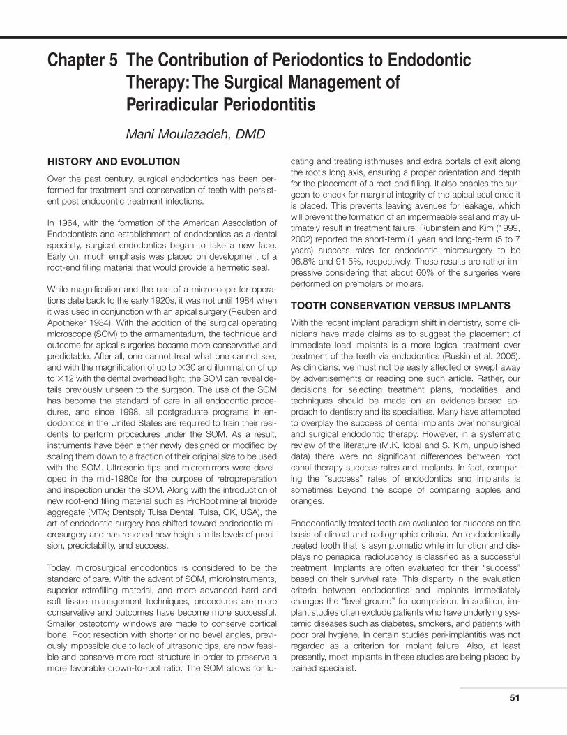
HISTORY AND EVOLUTION
Over the past century, surgical endodontics has been per-formed for treatment and conservation of teeth with persist-ent post endodontic treatment infections.
In 1964, with the formation of the American Association ofEndodontists and establishment of endodontics as a dentalspecialty, surgical endodontics began to take a new face.Early on, much emphasis was placed on development of aroot-end filling material that would provide a hermetic seal.
While magnification and the use of a microscope for opera-tions date back to the early 1920s, it was not until 1984 whenit was used in conjunction with an apical surgery (Reuben andApotheker 1984). With the addition of the surgical operatingmicroscope (SOM) to the armamentarium, the technique andoutcome for apical surgeries became more conservative andpredictable. After all, one cannot treat what one cannot see,and with the magnification of up to �30 and illumination of upto �12 with the dental overhead light, the SOM can reveal de-tails previously unseen to the surgeon. The use of the SOMhas become the standard of care in all endodontic proce-dures, and since 1998, all postgraduate programs in en-dodontics in the United States are required to train their resi-dents to perform procedures under the SOM. As a result,instruments have been either newly designed or modified byscaling them down to a fraction of their original size to be usedwith the SOM. Ultrasonic tips and micromirrors were devel-oped in the mid-1980s for the purpose of retropreparationand inspection under the SOM. Along with the introduction ofnew root-end filling material such as ProRoot mineral trioxideaggregate (MTA; Dentsply Tulsa Dental, Tulsa, OK, USA), theart of endodontic surgery has shifted toward endodontic mi-crosurgery and has reached new heights in its levels of preci-sion, predictability, and success.
Today, microsurgical endodontics is considered to be thestandard of care. With the advent of SOM, microinstruments,superior retrofilling material, and more advanced hard andsoft tissue management techniques, procedures are moreconservative and outcomes have become more successful.Smaller osteotomy windows are made to conserve corticalbone. Root resection with shorter or no bevel angles, previ-ously impossible due to lack of ultrasonic tips, are now feasi-ble and conserve more root structure in order to preserve amore favorable crown-to-root ratio. The SOM allows for lo-
cating and treating isthmuses and extra portals of exit alongthe root’s long axis, ensuring a proper orientation and depthfor the placement of a root-end filling. It also enables the sur-geon to check for marginal integrity of the apical seal once itis placed. This prevents leaving avenues for leakage, whichwill prevent the formation of an impermeable seal and may ul-timately result in treatment failure. Rubinstein and Kim (1999,2002) reported the short-term (1 year) and long-term (5 to 7years) success rates for endodontic microsurgery to be96.8% and 91.5%, respectively. These results are rather im-pressive considering that about 60% of the surgeries wereperformed on premolars or molars.
TOOTH CONSERVATION VERSUS IMPLANTS
With the recent implant paradigm shift in dentistry, some cli-nicians have made claims as to suggest the placement ofimmediate load implants is a more logical treatment overtreatment of the teeth via endodontics (Ruskin et al. 2005).As clinicians, we must not be easily affected or swept awayby advertisements or reading one such article. Rather, ourdecisions for selecting treatment plans, modalities, andtechniques should be made on an evidence-based ap-proach to dentistry and its specialties. Many have attemptedto overplay the success of dental implants over nonsurgicaland surgical endodontic therapy. However, in a systematicreview of the literature (M.K. Iqbal and S. Kim, unpublisheddata) there were no significant differences between rootcanal therapy success rates and implants. In fact, compar-ing the “success” rates of endodontics and implants issometimes beyond the scope of comparing apples andoranges.
Endodontically treated teeth are evaluated for success on thebasis of clinical and radiographic criteria. An endodonticallytreated tooth that is asymptomatic while in function and dis-plays no periapical radiolucency is classified as a successfultreatment. Implants are often evaluated for their “success”based on their survival rate. This disparity in the evaluationcriteria between endodontics and implants immediatelychanges the “level ground” for comparison. In addition, im-plant studies often exclude patients who have underlying sys-temic diseases such as diabetes, smokers, and patients withpoor oral hygiene. In certain studies peri-implantitis was notregarded as a criterion for implant failure. Also, at leastpresently, most implants in these studies are being placed bytrained specialist.
51
Chapter 5 The Contribution of Periodontics to EndodonticTherapy:The Surgical Management of Periradicular Periodontitis
Mani Moulazadeh, DMD

Meanwhile, the success of endodontic therapy as evaluatedby studies did not abide to the same strict patient exclusioncriteria as did the implant studies. Persistent radiographicdemineralization was considered to be a sign of failure. Last,the success rate of endodontic therapy as reported by suchstudies as the Toronto Study is based on treatments per-formed by dental students, general dentists, and endodon-tists. In 1999, American Dental Association reported that only25% of all endodontic cases were being performed by en-dodontists (ADA Report 1999).
It is clear that implants have changed the face of dentistryand the way we treatment plan restoring edentulous spaces.They are a great adjunct when treatment is planned properlyand when bone quality and aesthetics allow for their place-ment. Implants are clearly not an alternative for periodontallysound and endodontically treatable (nonsurgical or surgical)teeth. Retaining our patients’ healthy natural dentition shouldbe our main priority as health care providers.
TREATMENT OF FAILED ROOT CANALTHERAPY
When the initial root canal therapy has resulted in a negativeoutcome, two revisions are possible:
• Nonsurgical retreatment aimed to eliminate bacteria fromthe canal
• Surgical retreatment aimed to encapsulate bacteria insidethe canal
The decision as to which approach to take should be basedon the level of evidence and other criteria such as the den-tist’s training and experience, availability of the necessary ar-mamentarium, and the patient’s decision based on informedconsent.
Historically, nonsurgical retreatment has enjoyed a highersuccess rate than the surgical approach. Studies also sup-port that in the event of a surgical approach, prior nonsurgi-cal retreatment will increase the chance of a positive outcome(Zuolo 2000). Therefore, unless nonsurgical retreatment is notfeasible due to physical, anatomical, time, or financial hard-ships, surgical endodontics should not be considered as thetreatment of choice.
RATIONALE FOR ENDODONTIC SURGERY
Periapical surgery is performed to eradicate persistent infection/inflammation associated with teeth with previously negativepost-treatment outcome from either initial endodontic ther-apy or retreatment. With advancement in microsurgical en-dodontics, surgery should not be labeled as a last option, butit should be performed when either initial endodontic treat-ment or retreatment is not possible or feasibly cannot securea better outcome. Factors such as inability to properly access
the root canal system in order to adequately clean, shape,and obtain an apical seal may warrant surgery as the treat-ment of choice. The ability of the clinician to properly diag-nose which case is suitable for surgery is as important as hisor her clinical skills. It was Dr. Irving J. Naidorf who said, “Agood surgeon knows how to cut, and an excellent surgeonknows when to cut” (Kim 2002).
INDICATIONS FOR ENDODONTIC SURGERY
Anatomical Challenges
In certain cases, the tooth anatomy renders itself unwilling toproper debridement and obturation, leaving a portion of canaluntreated by nonsurgical methods. Teeth with canal block-ages due to severe calcification or with severe radicular cur-vatures fall under such category.
Also, in a few cases when endodontic therapy is performedat a clinically acceptable level, symptoms may continue topersist when the apex of the root may be fenestratingthrough the facial cortical plate of bone. In these cases, asmall surgical procedure to recontour the root end and alignit within its bony housing may solve the problem.
Iatrogenic Factors
Previous endodontic “misadventures” account for the needfor surgery in cases with persistent symptoms. These includebut are not limited to canal blockages, ledges, perforations,separated instruments or posts, underfilled canals, andcanals with dental material extruding beyond the biologicallytolerant buffer zone around the anatomical apex (Figs. 5.1through 5.3).
In most of these cases, proper canal debridement is compro-mised as is the ability to properly obturate the canal and ob-tain a proper apical seal.
52 Practical Advanced Periodontal Surgery
Fig. 5.1. Persistent inflammation associated with the mesial root of amandibular molar with a separated instrument.
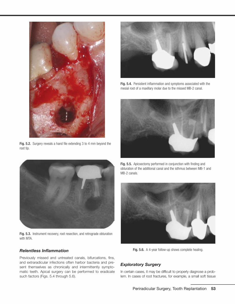
Relentless Inflammation
Previously missed and untreated canals, bifurcations, fins,and extraradicular infections often harbor bacteria and pre-sent themselves as chronically and intermittently sympto-matic teeth. Apical surgery can be performed to eradicatesuch factors (Figs. 5.4 through 5.6).
Exploratory Surgery
In certain cases, it may be difficult to properly diagnose a prob-lem. In cases of root fractures, for example, a small soft tissue
Periradicular Surgery, Tooth Replantation 53
Fig. 5.3. Instrument recovery, root resection, and retrograde obturationwith MTA.
Fig. 5.4. Persistent inflammation and symptoms associated with themesial root of a maxillary molar due to the missed MB-2 canal.
Fig. 5.6. A 4-year follow-up shows complete healing.
Fig. 5.5. Apicoectomy performed in conjunction with finding andobturation of the additional canal and the isthmus between MB-1 andMB-2 canals.
Fig. 5.2. Surgery reveals a hand file extending 3 to 4 mm beyond theroot tip.

flap followed by dying the area in question with methylene blueand inspection under the SOM can quickly reveal a root fracture,which can then prevent unnecessary endodontic treatment tobe performed on a nonrestorable tooth (Figs. 5.7 and 5.8).
Also, collection of a biopsy specimen may be another indica-tion for performing an exploratory surgery.
CONTRAINDICATIONS FOR ENDODONTICSURGERY
Medical History
Patients with recent myocardial infarction, with uncontrolleddiabetes, patients who are under anticoagulant therapy, pa-tients who received head and neck radiation, or patients withsevere neutropenia are not good candidates for surgery.Surgery should be postponed until they are cleared by theirtreating physician.
Compromised Periodontium
Periodontal pockets and tooth mobility reduce the success of en-dodontic surgery. High success rates in endodontic microsurgerywas achieved in studies where the prospective teeth did notexhibit any pathologic periodontal pocketing or pocketing thateither communicated with the apical endodontic componentor had completely denuded the buccal or lingual cortical plateof bone resulting in a dehiscence (Rubinstein and Kim 1999).
Skill, Knowledge, and Proper Instruments
General practitioners must be knowledgeable to properly diag-nose and refer patients with surgical needs to surgeons who havethe specialized training in diagnosing and treating these cases.
Although the skill levels of the surgeons should theoretically bethe same, in reality this may not be the case. A study reviewedthe outcome of treatment in the oral surgical and endodonticsdepartments of a teaching hospital 4 years following surgery.Complete healing for cases performed by the endodontic unitwas nearly twice as high for those performed in the oral sur-gery unit. The single most important contributing factor wasthe quality of the procedure, which in turn translated into thesurgeon’s skill and perhaps level of training and understand-ing of the problem at hand (Rahbaran 2001).
Despite the surgeon’s highest level of clinical competence,proper instrumentation is required for achieving the highestlevel of technical excellence. It may sound anecdotal, but it isimpractical for a world class skier to win any race while ski-ing on tennis rackets!
Finally, surgeons must keep the welfare of the patient in mindat all times. Case selection for surgery is very important, andindiscriminant use of surgeries to treat endodontic problemsis discouraged. Remember, just because you can, does notmean you should (Figs. 5.9 and 5.10).
Anatomical Challenges
Proximity to the maxillary sinus, mental nerve, and inferior alve-olar canal and the thickness of the buccal bone in the mandib-ular second molar area due to the external oblique ridge mayserve as a contraindication or deterrent for surgery. As long asa properly trained clinician is aware of such hurdles and con-ceivably knows how to work around them and manage mid-procedure and postprocedure potential complications, thesefactors may be downgraded to potential risks or contraindica-tions. Extra caution or modifications in the procedure may berequired in order to avoid damage to such structures.
As an example, the roots of many maxillary molars and pre-molars are separated from the maxillary sinus by a thin layerof cortical bone and the Schneiderian membrane. Care mustbe taken not to violate this space. However, in the event thatthe sinus is inadvertently perforated, with proper care, the
54 Practical Advanced Periodontal Surgery
Fig. 5.7. Multiple sinus tracts trace to the location of the endodonticlesion.
Fig. 5.8. An exploratory surgery and staining reveal a vertical rootfracture.

membrane usually heals uneventfully, without any negativeeffect on the outcome of the apical surgery (Fig. 5.11).
Inadequate Root Length
As a critical part of thorough treatment planning, the length ofthe root before surgery must be estimated. This will allow theclinician to have an understanding whether a favorable crownto root ratio is achievable once the root is resected. If the lengthof the root after resection is conceived to be inadequate, thismay be ground for aborting the surgical procedure and lookingfor an alternative plan. Although, in select cases where patientis free of periodontal disease, parafunctional habits, and mal-occlusion, teeth have been known to survive with as low as 1:1crown-to-root ratio (Figs. 5.12 through 5.14).
Periradicular Surgery, Tooth Replantation 55
Fig. 5.9. Apicoectomy was per-formed on a “calcified” central inci-sor without treating the tooth bynonsurgical root canal therapy first.
Fig. 5.10. Nonsurgical root canaltreatment was performed with theaid of the SOM. The tooth was freeof symptoms thereafter.
Fig. 5.11. Osteotomy and stained resected root ends of a maxillarymolar. Note the maxillary sinus and its lining deep to the root tips.
Fig. 5.12. Failing apicoectomy and sinus tract tracing in a maxillarysecond premolar.
Fig. 5.13. Conservative apicoectomy and obturation with MTA was per-formed despite the unfavorable crown-to-root ratio.
Fig. 5.14. Five-year recall revealed complete healing with no signs ofthe sinus tract or presence of mobility.

TYPES OF ENDODONTIC SURGERY
Incision and Drainage
Incision and drainage is used for treating necrotic teeth withacute apical abscess. After primary drainage through thetooth is established by performing a pulpectomy, a small in-cision is made at the base of the fluctuant swelling. Blunt dis-section with a curved hemostat facing the bone plate is car-ried out to dissect tissue plains and establish furtherdrainage. A drain must be placed for up to 48 hours to pre-vent wound closure. Keeping the incision site open will en-sure continuous drainage and patient comfort by allowing thepressure to be relieved (Fig. 5.15).
In addition, by allowing oxygen to gain access to the site ofinfection, the anaerobic bacteria are killed, the balance ofbacteria colony is disrupted, and the rate of healing may beaccelerated.
Root Amputation and Hemisection
Root amputation and hemisection involve surgical removaland surgical division of roots of multirooted teeth. Althoughonce performed more frequently, with the increased preva-lence of dental implants, the frequency is declining. It is pre-ferred that if a tooth is treatment planned for either of thesetwo procedures, the root canal treatment is performed beforethe surgical phase. It should be noted that with proper caseselection, both procedures are viable options for maintainingthe natural teeth. As prudent dentists, we must subdue oururges to perform “herodontics” at all cost in order to maintaina tooth in the oral cavity. Teeth that may serve as strategicabutments, exhibit advanced periodontitis or nonrestorable
remaining segment, and have fused roots or very low furca-tions are not good candidates for these types of surgery.
Intentional Replantation
As defined by Dr. Grossman, replantation is “the purposefulremoval of a tooth and its almost immediate replacementwith the object of obturating the canals apically while thetooth is out of its socket” (Kim 2001). Intentional replantationis an artificial setting mimicking complete tooth avulsion, andits management as defined by the guidelines of the AmericanAssociation of Endodontists. However, the circumstancingfactors are near ideal. The level of tooth contamination andphysical damage is likely to be far less than in the case of anaccidental injury. Moreover, the single most important factorin the demise of an avulsed tooth, the extraoral dry time, isnot a factor because it is practically nonexistent. During in-tentional replantation, the tooth is immediately submerged intissue culture medium, with the tooth out-of-socket timesbeing under 10 minutes.
The procedure dates back to the late 1500s, when Paré re-planted three avulsed teeth (Kupfer 1952). Intentional replan-tation has been performed for over half a century with suc-cess rates being reported between 80% and 95% forfollow-ups of 2 to 22 years by Grossman, Kingsbury, andBender (Kim 2001). Although many of these teeth exhibitedsome degree of ankylosis and replacement resorption, theywere clinically functional and did not exhibit any signs of peri-radicular pathosis. With the development of new protocolsthat call for the use of Hanks balanced salt solution (HBSS)(BioWhittaker, Walkersville, MD, USA) as an intermediatestorage and operating medium, and the use of enamel ma-trix derived protein (Emdogain; Straumann, Waldenburg,Switzerland) along with careful extraction techniques to pre-vent damage to the cementum and the PDL cells, thechances of resorption can be minimized.
Indications and Case Selection
Intentional replantation should not be the treatment of choiceif endodontic retreatment or surgery can be performed with aforeseeable positive outcome. Intentional replantation may beconsidered to be the treatment of choice for treatment ofcases where surgical access to the site is impractical or im-possible. Teeth with root perforations in mesial, distal, or fur-cal regions are great candidates. Teeth with expected elabo-rate apical anatomy and portals of exit or teeth where theapices are lying deep within the jaw bone and surgical accessis difficult are also good candidates.
Case selection in intentional replantation plays a big role onthe success of the treatment. Teeth with conical fused rootsare generally good candidates because of their ease of ex-traction. On the other hand, teeth with periodontal involve-ment, thick interseptal bone, or dilacerated roots are con-traindicated for intentional replantation.
56 Practical Advanced Periodontal Surgery
Fig. 5.15. Incision and drainage of an intraoral abscess. Note the latexdrain was sutured to prevent its premature removal.
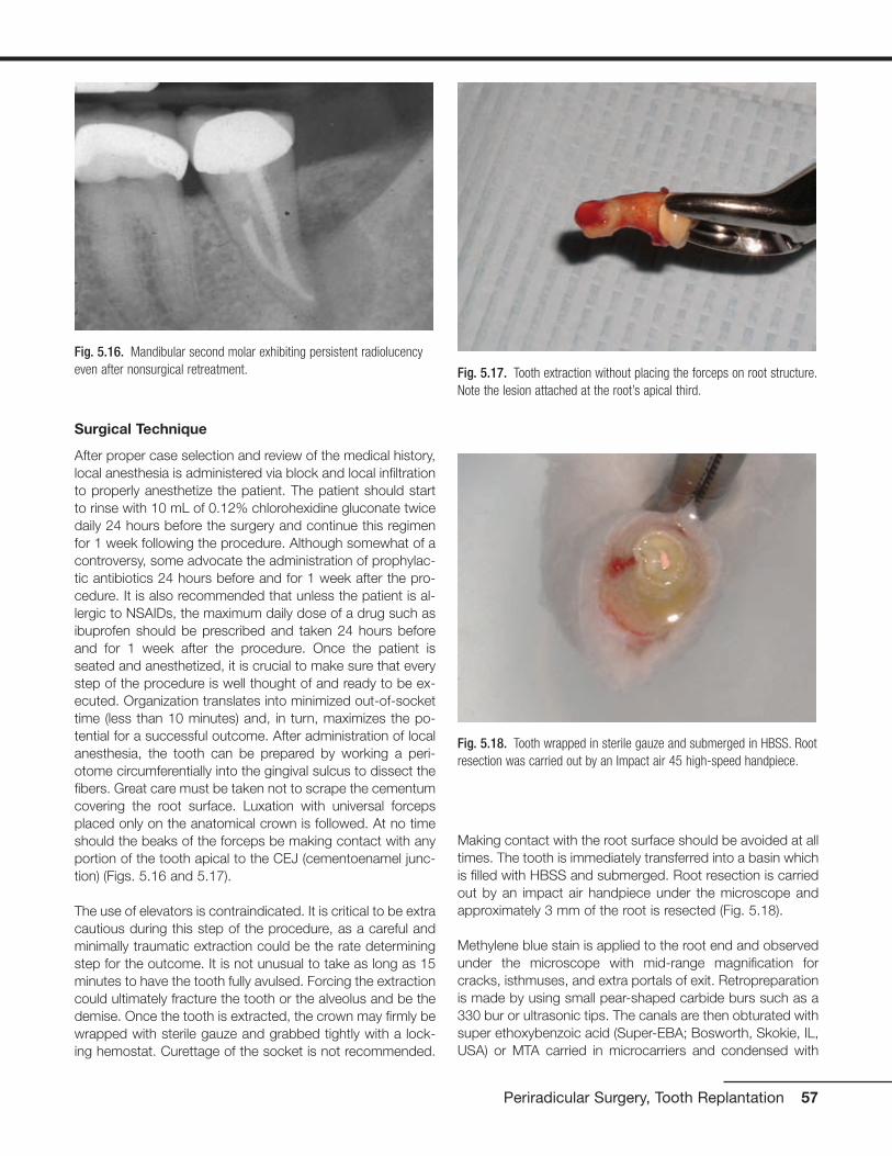
Surgical Technique
After proper case selection and review of the medical history,local anesthesia is administered via block and local infiltrationto properly anesthetize the patient. The patient should startto rinse with 10 mL of 0.12% chlorohexidine gluconate twicedaily 24 hours before the surgery and continue this regimenfor 1 week following the procedure. Although somewhat of acontroversy, some advocate the administration of prophylac-tic antibiotics 24 hours before and for 1 week after the pro-cedure. It is also recommended that unless the patient is al-lergic to NSAIDs, the maximum daily dose of a drug such asibuprofen should be prescribed and taken 24 hours beforeand for 1 week after the procedure. Once the patient isseated and anesthetized, it is crucial to make sure that everystep of the procedure is well thought of and ready to be ex-ecuted. Organization translates into minimized out-of-sockettime (less than 10 minutes) and, in turn, maximizes the po-tential for a successful outcome. After administration of localanesthesia, the tooth can be prepared by working a peri-otome circumferentially into the gingival sulcus to dissect thefibers. Great care must be taken not to scrape the cementumcovering the root surface. Luxation with universal forcepsplaced only on the anatomical crown is followed. At no timeshould the beaks of the forceps be making contact with anyportion of the tooth apical to the CEJ (cementoenamel junc-tion) (Figs. 5.16 and 5.17).
The use of elevators is contraindicated. It is critical to be extracautious during this step of the procedure, as a careful andminimally traumatic extraction could be the rate determiningstep for the outcome. It is not unusual to take as long as 15minutes to have the tooth fully avulsed. Forcing the extractioncould ultimately fracture the tooth or the alveolus and be thedemise. Once the tooth is extracted, the crown may firmly bewrapped with sterile gauze and grabbed tightly with a lock-ing hemostat. Curettage of the socket is not recommended.
Making contact with the root surface should be avoided at alltimes. The tooth is immediately transferred into a basin whichis filled with HBSS and submerged. Root resection is carriedout by an impact air handpiece under the microscope andapproximately 3 mm of the root is resected (Fig. 5.18).
Methylene blue stain is applied to the root end and observedunder the microscope with mid-range magnification forcracks, isthmuses, and extra portals of exit. Retropreparationis made by using small pear-shaped carbide burs such as a330 bur or ultrasonic tips. The canals are then obturated withsuper ethoxybenzoic acid (Super-EBA; Bosworth, Skokie, IL,USA) or MTA carried in microcarriers and condensed with
Periradicular Surgery, Tooth Replantation 57
Fig. 5.16. Mandibular second molar exhibiting persistent radiolucencyeven after nonsurgical retreatment. Fig. 5.17. Tooth extraction without placing the forceps on root structure.
Note the lesion attached at the root’s apical third.
Fig. 5.18. Tooth wrapped in sterile gauze and submerged in HBSS. Rootresection was carried out by an Impact air 45 high-speed handpiece.

micropluggers. The root end is then polished or burnishedand inspected one last time under the microscope before re-plantation (Fig. 5.19).
The tooth is then reoriented properly and gently placed in itssocket. Light apical pressure is applied until the tooth isseated in its correct, most apical position. It is prudent to ra-diographically confirm the complete seating of the tooth inthe socket at this time (Fig. 5.20).
The tooth is then splinted by suturing a monofilament sutureover the occlusal surface of the tooth. Fishing line and com-posite bonding can also be used by providing a physiologicalsplint when the treated tooth is splinted to its neighbor on theirbuccal surfaces. The limitation of this method is that it requiresboth of the teeth being splinted to have enamel on their buc-cal surfaces to facilitate bonding. This method excludes teeth
with metal or porcelain coronal coverage, which may be agood number of teeth treated by intentional replantation. Thepatient should be instructed to maintain a maximum intercus-pal position at least for the remainder of the day and to chewaway from the side for about 1 week. Postoperative instruc-tions are given and the patient should be reappointed forfollow-up visit in 1 week, at which time the sutures are re-moved if still intact. Pain management instructions are givenas described earlier. Once regarded as a last resort before ex-traction, today intentional replantation in selected cases is aviable and logical mode of treatment. With the development ofnew protocols for intentional replantation, the procedure hasbecome more predictable and should always be consideredas a part of possible treatment planning (Fig. 5.21).
PERIRADICULAR SURGERY
Periradicular surgeries, otherwise known as apicoectomy,constitute the bulk of endodontic surgeries. By definition, api-coectomy involves the reflection of a soft tissue flap, os-teotomy of both cortical and cancellous bone, and resectionof the root segment, which is suspected to be associatedwith a persistent inflammatory process. The preparation of aretrocavity and placement of a root-end filling material are notnecessary requirements for an apicoectomy, although theyare highly recommended. Apicoectomy is perceived to betechnically more difficult than other endodontic surgeries dueto difficulties in its accessibility, illumination, and small operat-ing field. This is especially true with the case of posteriorteeth, that the access more than the anatomy renders themmore difficult to treat (Wang 2004). However, since the addi-tion of the SOM to our arsenal of armamentarium, we havebeen able to overcome many of the challenges associatedwith apicoectomy.
Indications
Apicoectomy is indicated for treatment of teeth with persist-ent apical or periradicular pathosis due to anatomical chal-
58 Practical Advanced Periodontal Surgery
Fig. 5.21. Two-year recall exhibits complete healing.
Fig. 5.19. White MTA retrofill.
Fig. 5.20. Radiograph immediately post reimplantation

lenges, iatrogenic factors, irretrievable dental material insideand outside of the canal, fractures, and repair of resorptionsor perforations (Figs. 5.22 to 5.25).
PHASES OF APICOECTOMY AND SURGICALTECHNIQUE
Review of Medical History
Once the patient has been selected as a candidate for apicalsurgery, a complete review of the systemic health of the pa-tient must be performed. High-risk patients as defined by theAmerican Heart Association are to be pretreated prophylacti-cally with oral antibiotics. After consultation with their physi-cian, patients who are on anticoagulant therapy should be
taken off of the medication in time before the surgery. Last,patients who have been on oral or intravenous bisphospho-nates should be informed about the potential risks and com-plications that may arise after the surgery as sequelae of thedrug therapy.
Intraoral Examination
A thorough intraoral examination is crucial in postulating anddesigning the appropriate approach for treatment via sur-gery. Intraorally, the surgical site should be investigated forany type of periodontal defect by careful probing. Evaluationof periodontal recession, width of attached gingiva, and the patient’s gingival biotype may ultimately determine the
Periradicular Surgery, Tooth Replantation 59
Fig. 5.22. Sinus tract tracing and the location of the mid-root radiolu-cency is suggestive of a post perforation.
Fig. 5.23. Upon the reflection of the soft tissue flap, an isolated en-dodontic fenestration is visible.
Fig. 5.24. Staining reveals a perforation on the mesial aspect of theroot. The defect was filled with Super-EBA cement.
Fig. 5.25. A 3-month recall revealed partial healing and no signs of thesinus tract.

type of incision used during the surgery. Any sinus tracts,swellings, or areas sensitive to palpation should be noted.Evaluation of muscle attachments and patient’s opening arecritical in determining accessibility to the prospective surgi-cal site.
Radiographic Examination
Exposure of two periapical radiographs is the minimum re-quirement before commencement of surgery. The first radi-ograph should be exposed using a paralleling technique andthe second should be deviated in its horizontal componentby 20 degrees to the mesial or distal. The radiograph shouldbe studied for root length, number of roots, root curvature,size of the potential lesion, and proximity of the osteotomy toneurovascular bundles, maxillary sinus, and neighboringteeth. It is strongly recommended that, when possible, apanoramic radiograph is obtained, especially when treatingmandibular posterior teeth.
Presurgical Preparation
Preoperatively, unless contraindicated, the patient should take600 to 800 mg of ibuprofen just before surgery. The patientshould continue to take this regimen of anti-inflammatoryevery 8 hours for up to 3 days after the surgery.
In addition, the patient should commence rinsing with 10 mLof 0.12% chlorohexidine gluconate twice daily, 24 hours be-fore surgery. This oral rinse should be used before surgery toreduce the quantity of the microorganisms in the mouth anddecrease the chance of a postsurgical flap infection.
Local Anesthesia (Pain Control andHemostasis)
Choosing and administering the appropriate local anesthetichas a trifold effect. First, it provides pain control during thesurgery. Second, it provides hemostasis. Third, by adminis-tering a long-lasting anesthetic, postoperatively, the cycle ofpain is broken. This is in part due to prevention in amplifica-tion of responses from the peripheral nerves, which could ul-timately lead to central sensitization.
Typically, local anesthesia is administered via nerve blocksand local infiltrations. Nerve blocks are aimed at achievingprofound pain control but must be supplemented by local in-filtrations and papillary injections on both the buccal andlingual aspects of the teeth for additional pain control andhemostasis.
Unless contraindicated, 2% lidocaine with 1:50,000 epineph-rine is the anesthetic of choice because of its high concen-tration of epinephrine, which is suitable for hemostasis.Although this high concentration of epinephrine may cause atransient tachycardia in the patient, the effects are generallyshort lived. It should be noted that some clinicians prefer 3%
Marcaine with epinephrine for nerve block because of its longduration of action.
In addition to the administration of one cartridge of anestheticfor the appropriate nerve block when working on maxillary ormandibular teeth, local infiltration into oral tissue for hemosta-sis is required. Generally, up to two cartridges of anestheticshould be infiltrated locally around two or three teeth on ei-ther side of the surgical site. Because most of the receptorsin the masticatory mucosa are of �–adrenergic type, oncebound to epinephrine, they produce a desired vasoconstric-tive effect. In contrast, because the majority of the receptorsin skeletal muscles are of the ß2–adrenergic variety and theirbinding to epinephrine causes vasodialation, care must betaken to prevent injecting deep into these tissues.
Soft Tissue Flap Design
Proper flap design not only should provide easy access to the location of the pathosis but also should consider and pro-vide postsurgical aesthetics of the periodontium and the gin-giva, especially preserving marginal gingiva and papillaryheights. With the evolution of periodontal surgery and intro-duction of new techniques, some older techniques havebeen phased out.
Periodontal condition of the failing tooth and its neighboringteeth play an important role in the design of the soft tissueflap; so does the prosthetic state of the surgical site. Whenworking on teeth with crowns or areas near the pontic of afixed partial denture, modifications to the incision line may beneeded to facilitate suturing and ensure soft tissue aestheticsin the long term. Also of importance are anatomical factors,such as the mental foramen, which may ultimately play a rolein the selection of the location for the placement of the verti-cal release incision.
In endodontic surgery, incisions are made to facilitate eleva-tion and reflection of a full-thickness flap. Generally, a hori-zontal component and two vertical release incisions are usedto provide easy access without pulling and tearing the cor-ners of the flap. Once the tissue is reflected, great care mustbe taken to prevent the placement of the retractors on softtissue. Many manufacturers have developed contour specificretractors that provide good ergonomic retraction of the flapin different locations of the mouth. In some cases, slipping ofthe retractor can be prevented by placing a notch or a groovesuperficially on the cortical bone and subsequently placingthe retractor in this groove.
The following is a list of flaps that are associated with en-dodontic surgery:
Semilunar Incision
Although once frequently used by endodontists and oral sur-geons for performing apicoectomies, semilunar incisions are
60 Practical Advanced Periodontal Surgery

an inferior and obsolete technique. Typically, they providepoor access to the site and do not allow for addressing ortreating periodontal–endodontic involvements. They often re-sult in unsightly scars as the incision line is made in unat-tached, mobile oral mucosa, and over the osteotomy wherehealing by primary intention is impractical, if not impossible.
Today, semilunar incisions are performed only during emer-gency incision and drainage.
Full-Thickness Intrasulcular Incision
In this technique, the horizontal incision commences at thebase of the gingival sulcus and is carried through to the crestof the bone by dissecting the periodontal ligament fibers.Generally, the horizontal component should be extended bythe width of two teeth on either side of the tooth beingtreated. Interproximally, the incision should be made with asharp 15C or a CK-2 microblade (Sybron Endo, Orange, CA,USA) lingually while following the contour of the teeth. Thecomplete dissection of the interdental papilla before elevationis desired to prevent recession and formation of “black trian-gles” postoperatively.
Two variations of the full thickness intrasulcular flap exist:
• The triangular flap, which uses one vertical releasing inci-sion in the more medial aspect of the flap, typically requiresa longer horizontal incision. The releasing incision shouldbegin perpendicular to the line of the free gingival marginfor a short distance of approximately 2 to 3 mm. It is thenrounded off at the corner and transitioned into the verticalcomponent of the releasing incision. It is not unusual to ex-tend the release incision up to the mucobuccal fold and upto 2 times the length of release incisions in periodontal sur-gery in order to access the root apex easily. Triangular flapsare commonly used in surgeries of the posterior region
(Figs. 5.26 to 5.28), or in the anterior region when treatingteeth with cervical resorptions or perforations.
• The rectangular flap is similar to the triangular flap, exceptit uses two vertical releasing incisions and as a result, thehorizontal incision may be shorter. This flap provides betteraccess to the apex of anterior teeth than the triangular flap.
Full-Thickness Submarginal Incision
Also known as the mucogingival flap, it is indicated primarilyin anterior surgeries to treat teeth with crowns and whereaesthetics of the crown margin is of a great deal of impor-tance. The beveled scalloped horizontal component of the in-cision is placed in attached gingiva and is terminated byrounding off and transitioning into the placement of two par-allel vertical releasing incisions at either end. The scallopingaids in exact repositioning of the flap postsurgically to ensure
Periradicular Surgery, Tooth Replantation 61
Fig. 5.26. Maxillary first molar exhibiting persistent symptoms despitethe radiographically acceptable appearance of the nonsurgical root canaltherapy.
Fig. 5.27. Triangular full-thickness flap provides access to the surgicalsite.
Fig. 5.28. Apicoectomy and retrofill with MTA was performed on allthree roots via a buccal approach.
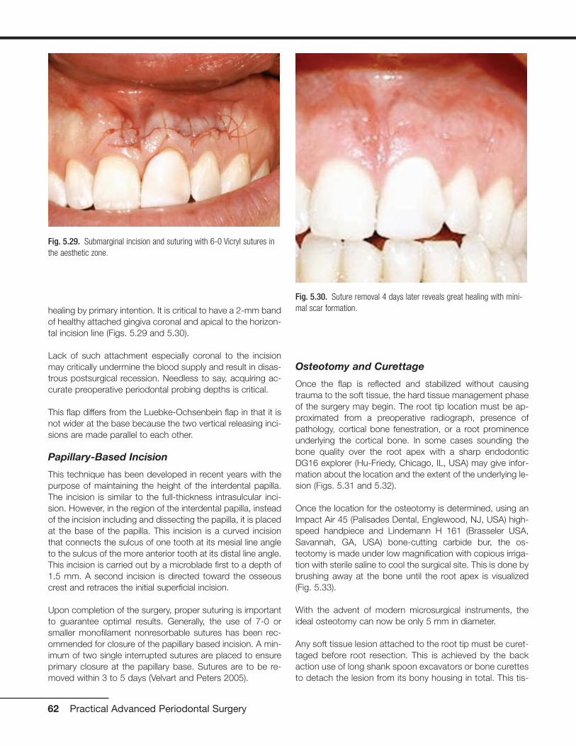
healing by primary intention. It is critical to have a 2-mm bandof healthy attached gingiva coronal and apical to the horizon-tal incision line (Figs. 5.29 and 5.30).
Lack of such attachment especially coronal to the incisionmay critically undermine the blood supply and result in disas-trous postsurgical recession. Needless to say, acquiring ac-curate preoperative periodontal probing depths is critical.
This flap differs from the Luebke-Ochsenbein flap in that it isnot wider at the base because the two vertical releasing inci-sions are made parallel to each other.
Papillary-Based Incision
This technique has been developed in recent years with thepurpose of maintaining the height of the interdental papilla.The incision is similar to the full-thickness intrasulcular inci-sion. However, in the region of the interdental papilla, insteadof the incision including and dissecting the papilla, it is placedat the base of the papilla. This incision is a curved incisionthat connects the sulcus of one tooth at its mesial line angleto the sulcus of the more anterior tooth at its distal line angle.This incision is carried out by a microblade first to a depth of1.5 mm. A second incision is directed toward the osseouscrest and retraces the initial superficial incision.
Upon completion of the surgery, proper suturing is importantto guarantee optimal results. Generally, the use of 7-0 orsmaller monofilament nonresorbable sutures has been rec-ommended for closure of the papillary based incision. A min-imum of two single interrupted sutures are placed to ensureprimary closure at the papillary base. Sutures are to be re-moved within 3 to 5 days (Velvart and Peters 2005).
Osteotomy and Curettage
Once the flap is reflected and stabilized without causingtrauma to the soft tissue, the hard tissue management phaseof the surgery may begin. The root tip location must be ap-proximated from a preoperative radiograph, presence ofpathology, cortical bone fenestration, or a root prominenceunderlying the cortical bone. In some cases sounding thebone quality over the root apex with a sharp endodonticDG16 explorer (Hu-Friedy, Chicago, IL, USA) may give infor-mation about the location and the extent of the underlying le-sion (Figs. 5.31 and 5.32).
Once the location for the osteotomy is determined, using anImpact Air 45 (Palisades Dental, Englewood, NJ, USA) high-speed handpiece and Lindemann H 161 (Brasseler USA,Savannah, GA, USA) bone-cutting carbide bur, the os-teotomy is made under low magnification with copious irriga-tion with sterile saline to cool the surgical site. This is done bybrushing away at the bone until the root apex is visualized(Fig. 5.33).
With the advent of modern microsurgical instruments, theideal osteotomy can now be only 5 mm in diameter.
Any soft tissue lesion attached to the root tip must be curet-taged before root resection. This is achieved by the backaction use of long shank spoon excavators or bone curettesto detach the lesion from its bony housing in total. This tis-
62 Practical Advanced Periodontal Surgery
Fig. 5.29. Submarginal incision and suturing with 6-0 Vicryl sutures inthe aesthetic zone.
Fig. 5.30. Suture removal 4 days later reveals great healing with mini-mal scar formation.

sue must be submitted for biopsy. Any remnants still at-tached to the root can be removed via a 34/35 Jaquettescaler or a 13/14 periodontal curette (Hu- Friedy). Excessivecurettage of the bony crypt may cause excessive bleeding,which may in turn complicate and compromise the stagesof root-end resection, retropreparation, and retrofilling.Therefore, it may be more strategic to leave small amountsof granulation tissue behind and clean it after the root-endfilling is placed.
The Impact Air 45 high-speed handpiece is designed in suchway that only a water coolant is sprayed out from the frontonto the bur. The air jet is contained within a closed circuitand ejected from the rear of the handpiece. This innovationallows for a much cleaner operation due to the lack of splat-ter previously caused by the air stream forced out of the head
of conventional handpieces. Most important, it creates asafer operation by eliminating the air that may be forced intothe open vessels of the surgical site and potentially cause anair emphysema.
Root Resection
The logic behind root resection and its extent is derived fromthe models developed by Hess. A 3-mm reduction in the rootend will decrease the incidence of lateral canals by 93% andapical ramifications by 98%. Therefore statistically, a 3-mmapicoectomy will markedly favor the elimination of persistentbacteria and undebrided tissue in the apical root canal por-tion (Kim 2001). This will also enable the surgeon to removeand eliminate iatrogenic factors more prevalent to the last 2to 3 mm of the root canal system. Once the root is resected,access to the canal is possible for evaluation and formationof an impervious retroseal.
Up until the early 1990s, the practice was to resect the rootend with a 45-degree buccolingual bevel. This was practicedbecause it was impossible to form a cavity preparation intothe canal even with the smallest handpiece. Presently, withthe development of microsurgical instruments, and, morespecifically, ultrasonic tips, micromirrors, and pluggers, therecommended root-end resection bevel angle is between 0and 10 degrees. This modification in technique has its manyadvantages. It conserves root and buccal cortical bone andreduces the chance of incomplete resection and perhapsmissing lingual anatomy. By reducing the cavity preparation,cavosurface margin, and number of exposed dentinaltubules, the risk of microleakage is reduced (Kim 2002).
This phase of the procedure should be carried out under mid-range magnification using the Impact Air 45 handpiece and
Periradicular Surgery, Tooth Replantation 63
Fig. 5.31. Failing root canal treatment on maxillary first and secondpremolars.
Fig. 5.33. Osteotomy is initiated by slow removal of the buccal corticalbone until the root tips are visible.
Fig. 5.32. Flap elevation reveals fenestrations over the root promi-nences identifying the location of the defects.
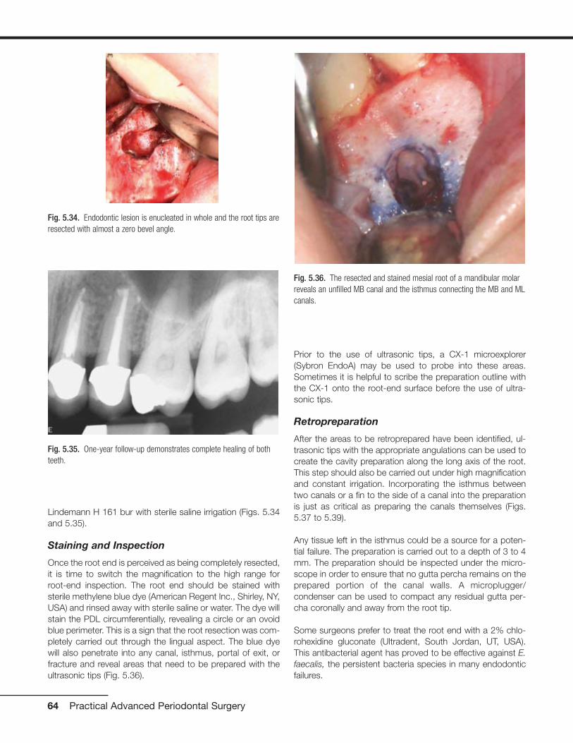
Lindemann H 161 bur with sterile saline irrigation (Figs. 5.34and 5.35).
Staining and Inspection
Once the root end is perceived as being completely resected,it is time to switch the magnification to the high range forroot-end inspection. The root end should be stained withsterile methylene blue dye (American Regent Inc., Shirley, NY,USA) and rinsed away with sterile saline or water. The dye willstain the PDL circumferentially, revealing a circle or an ovoidblue perimeter. This is a sign that the root resection was com-pletely carried out through the lingual aspect. The blue dyewill also penetrate into any canal, isthmus, portal of exit, orfracture and reveal areas that need to be prepared with theultrasonic tips (Fig. 5.36).
Prior to the use of ultrasonic tips, a CX-1 microexplorer(Sybron EndoA) may be used to probe into these areas.Sometimes it is helpful to scribe the preparation outline withthe CX-1 onto the root-end surface before the use of ultra-sonic tips.
Retropreparation
After the areas to be retroprepared have been identified, ul-trasonic tips with the appropriate angulations can be used tocreate the cavity preparation along the long axis of the root.This step should also be carried out under high magnificationand constant irrigation. Incorporating the isthmus betweentwo canals or a fin to the side of a canal into the preparationis just as critical as preparing the canals themselves (Figs.5.37 to 5.39).
Any tissue left in the isthmus could be a source for a poten-tial failure. The preparation is carried out to a depth of 3 to 4mm. The preparation should be inspected under the micro-scope in order to ensure that no gutta percha remains on theprepared portion of the canal walls. A microplugger/condenser can be used to compact any residual gutta per-cha coronally and away from the root tip.
Some surgeons prefer to treat the root end with a 2% chlo-rohexidine gluconate (Ultradent, South Jordan, UT, USA).This antibacterial agent has proved to be effective against E.faecalis, the persistent bacteria species in many endodonticfailures.
64 Practical Advanced Periodontal Surgery
Fig. 5.34. Endodontic lesion is enucleated in whole and the root tips areresected with almost a zero bevel angle.
Fig. 5.35. One-year follow-up demonstrates complete healing of bothteeth.
Fig. 5.36. The resected and stained mesial root of a mandibular molarreveals an unfilled MB canal and the isthmus connecting the MB and MLcanals.

Moisture Control
The bone crypt must be dry before the placement of theretrofill material. If bleeding is present, it may be controlled bythe application of topical hemostatic agents. Racellet #3(Pascal Co., Bellevue, WA, USA) epinephrine pellets are usu-ally effective in controlling the bleeding in most osteotomysites. They contain racemic epinephrine, which aid in hemo-stasis. These pellets are packed into the osteotomy site withmoderate pressure maintained on them for a few minutes.Once hemostasis is achieved, all but the last of the pellets areremoved. The last pellet is deliberately left in the crypt tomaintain the hemostasis. Aspiration into the crypt once he-mostasis has been achieved should be prevented, becauseit may draw blood out of the capillaries and initiate bleedingagain. It is important to keep track of the number of pelletsplaced, so at the end of the procedure, pellets are not forgot-ten and left behind.
For more persistent bleeding in larger osteotomies, ferric sul-fate solution such as Cut-Trol (Ichthys Inc., Mobile, AL, USA)may be used. Ferric sulfate has been shown to delay postop-erative healing (Lemon 1993). Therefore, it should only beused sparingly and currettaged and rinsed thoroughly at theend of the surgery before suturing.
Calcium sulfate such as Surgiplast (ClassImplant, Rome, Italy)can also be used as a mechanical barrier to promote hemo-stasis in large osteotomies. Calcium sulfate is an osteoinduc-tive resorbable agent that may act as a barrier against themore rapid mobilization of soft tissue cells towards the os-teotomy site and, therefore, promote bone formation.
Retrofill
Once the moisture is controlled, it is time for sealing the rootend. The root end must be irrigated and air dried with aStropko irrigator/drier with a microtip (Sybron Endo).
Although amalgam was once the root-end filling of choice,today it is no longer the standard of care to place amalgamas a retrograde filling. Today’s materials provide a better seal,do not tattoo the gingiva, do not corrode, and are more bio-compatible than amalgam. Although an array of materials arepresently available, MTA and Super-EBA are the most prom-ising and most widely used.
MTA exhibits many of the desired characteristics of a retrofillmaterial. MTA is radiopaque and gentle to the periapical tis-sue, induces cementogenesis, has great sealing ability, and istolerant to moisture. In fact, MTA requires moisture to hardenand set. Unfortunately, it is difficult to handle. MTA is mixedwith sterile water to form a wet sand–like granular mixture.The easiest way to place it into the root-end preparation is
Periradicular Surgery, Tooth Replantation 65
Fig. 5.37. Mandibular first molar exhibiting persistent pathology of themesial root.
Fig. 5.38. Apicoectomy, retropreparation, and retrofill of the MB and MLcanals and the isthmus connecting them.
Fig. 5.39. Near-complete healing is noted at 6-month recall appointment.

with the MAP System (Roydent, Johnson City, TN, USA) orthe MTA pellet forming block (G. Hartzell & Son, Concord,CA, USA). Once placed, MTA takes a long time to set andshould not be rinsed out. The crypt may be cleaned with amoist cotton pellet.
Super-EBA, on the other hand, is difficult to mix but easier tohandle. It is mixed into a hard, dull, dough-like mixture by in-corporating powder into liquid with a thick spatula over aglass slab. Once ready, time is limited to place it because itsets quickly, especially in the presence of heat and humidity.Super-EBA is rolled into a small cone and picked up in smallsegments with an instrument such as a Hollenbeck or theback side of a spoon excavator. It is then placed into the rootend, compacted gently with a microplugger, and finally bur-nished with a microball burnisher. After the material is fullyset, it may be polished with a composite finishing bur using ahigh speed handpiece with irrigation.
Once the retrofill material is placed, it is a good practice to ra-diographically verify the density and the depth of the fill be-fore suturing the flap. If any modifications need to be made,this is a good time for it.
After the quality of the filling is confirmed to be satisfactory,the crypt must be curettaged to remove any residual materialor coagulum and to induce bleeding. The surgical site shouldbe rinsed with sterile saline to wash off any particles or loosedebris and also to rehydrate the flap and the cortical bone,which may have been drying under the intense illuminationfrom the SOM.
Suturing and Suture Removal
The flap needs to be reapproximated passively before sutur-ing. Best results are obtained when the flap margins approx-imate without the use of force or under tension. For this pur-pose, a wet 2 � 2 guaze is compressed gently over the flapand cortical bone until tissue margins assume their preferredposition.
As for suture material, monofilament nonresorbable Prolene(Ethicon Inc., Somerville, NJ, USA) sutures in sizes of 6-0 orsmaller provide the optimal results. The advantage of thesetypes of sutures is that their size causes the least amount oftrauma and that they are nonresorbable, which minimizes theinflammation typically associated with suture materials. Whensuturing the apical margins of the vertical release incisionnear the mucobuccal fold, however, it is advantageous to usea resorbable suture such as a coated Vicryl or Monocryl(Ethicon Inc.). Sutures in this region sometimes have a ten-dency to become imbedded into the wound closure and maybe difficult to remove.
In terms of suturing technique, single interrupted and verticalmattress sutures are the most commonly used. Vertical mat-
tress sutures are preferred when suturing mobilized interden-tal papillae in the anterior esthetic zone. Sling sutures in theposterior region can be used in place of two single inter-rupted sutures. When suturing the vertical releasing incision,a continuous interlocking suture can be used to expedite su-turing by eliminating the need for multiple knots.
Whatever the suturing technique, care must be taken that thesuture and the knots are free of any tension. Tissue marginsmay be torn when sutures are tight and act as a guillotine. Inaddition, the underlying tissue may become deprived ofblood perfusion and ultimately necrose in presence of over-tighten knots.
Postsurgically, sutures should be removed within 3 to 5 days,although some studies advocate suture removal by 48 hours.
Postoperative Instructions
Postoperative instructions should be directed toward ensur-ing patient’s comfort, control of bleeding and swelling, andprevention of infections.
Patient reassurance is an important part of postoperative in-structions. It is better for the patient to know about potentialpain, swelling, or bruising ahead of time rather than beingcaught by surprise.
Pain following endodontic surgery is usually mild. For this rea-son non-narcotic analgesics are more than adequate in con-trolling patient’s pain. Just before the start of the procedure,1000 mg of acetaminophen or 800 mg of ibuprofen shouldbe taken by the patient as a preemptive strike against painwhen the local anesthetic slowly wears off. Postsurgically,ibuprofen 800 mg three times daily should be prescribed andtaken by the patient for 3 to 5 days. This regimen should befollowed regardless of the level of patient’s comfort as ananti-inflammatory medication. For those patients who are al-lergic to ibuprofen, 1000 mg acetaminophen can be takenfour times daily. Some more recent studies suggest combina-tion therapy with ibuprofen and acetaminophen will achievemore effective levels of analgesia (Menhinick 2004).
Applying an ice pack to the face over the region of surgerywith moderate pressure for 20 minutes on and 20 minutes offis very important in controlling inflammation, swelling, and ec-chymosis. This regimen is most effective if followed up to 8hours postsurgically. Moist heat application is recommendedfor 24 to 48 hours after surgery.
Rinsing with 10 mL of 0.12% chlorohexidine gluconate solu-tion twice daily should begin 24 hours before surgery andcontinue for up to 2 days after suture removal. Gentle brush-ing with a soft bristle tooth brush should be limited to theareas away from the surgical site and to the occlusal surfacesof teeth proximal to the incision line.
66 Practical Advanced Periodontal Surgery
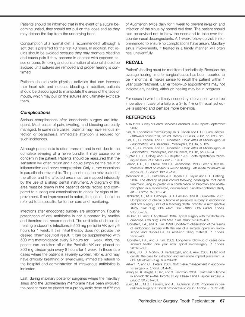
Patients should be informed that in the event of a suture be-coming untied, they should not pull on the loose end as theymay detach the flap from the underlying bone.
Consumption of a normal diet is recommended, although asoft diet is preferred for the first 48 hours. In addition, hot liq-uids should be avoided because they may promote bleedingand cause pain if they become in contact with exposed tis-sue or bone. Smoking and consumption of alcohol should beavoided until sutures are removed and proper healing is con-firmed.
Patients should avoid physical activities that can increasetheir heart rate and increase bleeding. In addition, patientsshould be discouraged to manipulate the areas of the face ormouth, which may pull on the sutures and ultimately extricatethem.
Complications
Serious complications after endodontic surgery are infre-quent. Most cases of pain, swelling, and bleeding are easilymanaged. In some rare cases, patients may have serious in-fection or parasthesia. Immediate attention is required forsuch incidences.
Although parasthesia is often transient and is not due to thecomplete severing of a nerve bundle, it may cause someconcern in the patient. Patients should be reassured that thesensation will often return and it could simply be the result ofinflammation and nerve compression. Only in rare occasionsis parasthesia irreversible. The patient must be reevaluated atthe office, and the affected area must be mapped intraorallyby the use of a sharp dental instrument. A diagram of thisarea must be drawn in the patient’s dental record and com-pared to subsequent examinations to check for signs of im-provement. If no improvement is noted, the patient should bereferred to a specialist for further care and monitoring.
Infections after endodontic surgery are uncommon. Routineprescription of oral antibiotics is not supported by studiesand therefore not recommended. The antibiotic of choice fortreating endodontic infections is 500 mg penicillin VK every 6hours for 1 week. If this initial therapy does not provide thedesired pharmaceutical result, it can be supplemented with500 mg metronidazole every 6 hours for 1 week. Also, thepatient can be taken off of the Penicillin VK and placed on300 mg clindamycin every 8 hours for 1 week. In those rarecases where the patient is severely swollen, febrile, and mayhave difficulty breathing or swallowing, immediate referral tothe hospital and administration of intravenous antibiotics isindicated.
Last, during maxillary posterior surgeries where the maxillarysinus and the Schneiderian membrane have been involved,the patient must be placed on a prophylactic dose of 875 mg
of Augmentin twice daily for 1 week to prevent invasion andinfection of the sinus by normal oral flora. The patient shouldalso be advised not to blow the nose and to take over-the-counter nasal decongestants. A 1-week follow-up visit is rec-ommended to ensure no complications have arisen. Maxillarysinus involvements, if treated in a timely manner, will oftenheal uneventfully.
RECALL
Patient’s healing must be monitored periodically. Because theaverage healing time for surgical cases has been reported tobe 7 months, it makes sense to recall the patient within 1year post-treatment. Earlier follow-up appointments may notindicate any healing, although healing may be in progress.
For cases in which a timely secondary intervention would beimperative in case of a failure, a 3- to 4-month recall sched-ule is justified and perhaps more beneficial.
REFERENCESADA 1999 Survey of Dental Services Rendered. ADA Report: September
2002.Kim, S. Endodontic microsurgery. In S. Cohen and R.C. Burns, editors.
Pathways of the Pulp, 8th ed. Mosby, St Louis, 2002, pp. 683–725.Kim, S., G. Pecora, and R. Rubinstein. Color Atlas of Microsurgery in
Endodontics. WB Saunders, Philadelphia, 2001a, p. 125.Kim, S., G. Pecora, and R. Rubinstein. Color Atlas of Microsurgery in
Endodontics. Philadelphia, WB Saunders, 2001b, pp. 85–94.Kupfer, I.J., R. Sidney, and B.S. Kupfer. 1952. Tooth replantation follow-
ing avulsion. N.Y. State Dent. J. 19:80.Lemon, R.R., P.J. Steele, and B.G. Jeansonne. 1993. Ferric sulfate he-
mostasis: effect on osseous wound healing. Left in-situ for maximumexposure. J. Endod. 19:170–173.
Menhinick, K., J.L. Gutmann, J.D. Regan, S.E. Taylor, and P.H. Bushang.2004. The efficacy of pain control following nonsurgical root canaltreatment using ibuprofen or a combination of ibuprofen and aceta-minophen in a randomized, double-blind, placebo-controlled study.Int. J. Endod. 37:531–541.
Rahbaran, S., M.S. Gilthorpe, S.D. Harrison, and K. Gulabivala. 2001.Comparison of clinical outcome of periapical surgery in endodonticand oral surgery units of a teaching dental hospital: a retrospectivestudy. Oral Surg. Oral Med. Oral Pathol. Oral Radiol. Endod.91:700–709.
Reuben, H., and H. Apotheker. 1984. Apical surgery with the dental mi-croscope. Oral Surg. Oral Med. Oral Pathol. 57:433–435.
Rubinstein, F.A., and S. Kim. 1999. Short-term observation of the resultsof endodontic surgery with the use of a surgical operation micro-scope and Super-EBA as root-end filling material. J. Endod.25:43–48.
Rubinstein, F.A., and S. Kim. 2002. Long-term follow-up of cases con-sidered healed one year after apical microsurgery. J. Endod.28:378–383.
Ruskin, J.D., D. Morton, B. Karayazgan, and J. Amir. 2005. Failed rootcanals: the case for extraction and immediate implant placement. J.Oral Maxillofac. Surg. 63:829–831.
Velvart, P., and C.I. Peters. 2005. Soft tissue management in endodon-tic surgery. J. Endod. 31:4–16.
Wang, N., K. Knight, T. Dao, and S. Friedman. 2004. Treatment outcomein endodontics—the Toronto study. Phase I and II: apical surgery. J.Endod. 30:751–761.
Zuolo, M.L., M.O.F. Ferreira, and J.L. Gutmann. 2000. Prognosis in peri-radicular surgery: a clinical prospective study. Int. Endod. J. 33:91–98.
Periradicular Surgery, Tooth Replantation 67
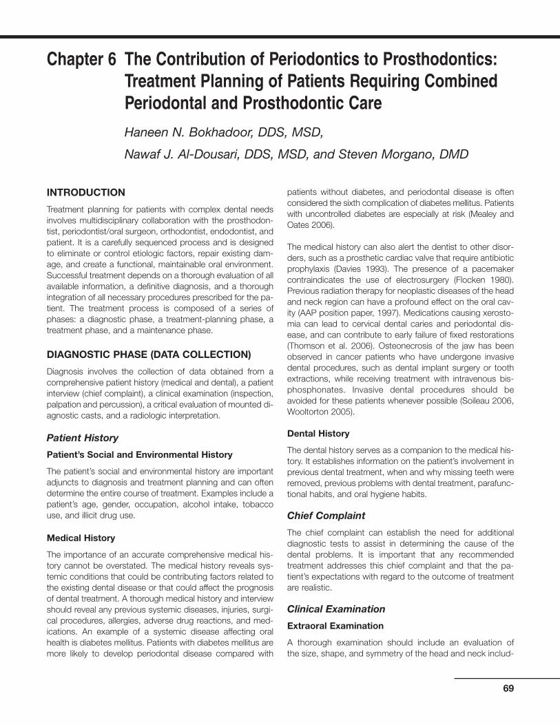
INTRODUCTION
Treatment planning for patients with complex dental needsinvolves multidisciplinary collaboration with the prosthodon-tist, periodontist/oral surgeon, orthodontist, endodontist, andpatient. It is a carefully sequenced process and is designedto eliminate or control etiologic factors, repair existing dam-age, and create a functional, maintainable oral environment.Successful treatment depends on a thorough evaluation of allavailable information, a definitive diagnosis, and a thoroughintegration of all necessary procedures prescribed for the pa-tient. The treatment process is composed of a series ofphases: a diagnostic phase, a treatment-planning phase, atreatment phase, and a maintenance phase.
DIAGNOSTIC PHASE (DATA COLLECTION)
Diagnosis involves the collection of data obtained from acomprehensive patient history (medical and dental), a patientinterview (chief complaint), a clinical examination (inspection,palpation and percussion), a critical evaluation of mounted di-agnostic casts, and a radiologic interpretation.
Patient History
Patient’s Social and Environmental History
The patient’s social and environmental history are importantadjuncts to diagnosis and treatment planning and can oftendetermine the entire course of treatment. Examples include apatient’s age, gender, occupation, alcohol intake, tobaccouse, and illicit drug use.
Medical History
The importance of an accurate comprehensive medical his-tory cannot be overstated. The medical history reveals sys-temic conditions that could be contributing factors related tothe existing dental disease or that could affect the prognosisof dental treatment. A thorough medical history and interviewshould reveal any previous systemic diseases, injuries, surgi-cal procedures, allergies, adverse drug reactions, and med-ications. An example of a systemic disease affecting oralhealth is diabetes mellitus. Patients with diabetes mellitus aremore likely to develop periodontal disease compared with
patients without diabetes, and periodontal disease is oftenconsidered the sixth complication of diabetes mellitus. Patientswith uncontrolled diabetes are especially at risk (Mealey andOates 2006).
The medical history can also alert the dentist to other disor-ders, such as a prosthetic cardiac valve that require antibioticprophylaxis (Davies 1993). The presence of a pacemakercontraindicates the use of electrosurgery (Flocken 1980).Previous radiation therapy for neoplastic diseases of the headand neck region can have a profound effect on the oral cav-ity (AAP position paper, 1997). Medications causing xerosto-mia can lead to cervical dental caries and periodontal dis-ease, and can contribute to early failure of fixed restorations(Thomson et al. 2006). Osteonecrosis of the jaw has beenobserved in cancer patients who have undergone invasivedental procedures, such as dental implant surgery or toothextractions, while receiving treatment with intravenous bis-phosphonates. Invasive dental procedures should beavoided for these patients whenever possible (Soileau 2006,Wooltorton 2005).
Dental History
The dental history serves as a companion to the medical his-tory. It establishes information on the patient’s involvement inprevious dental treatment, when and why missing teeth wereremoved, previous problems with dental treatment, parafunc-tional habits, and oral hygiene habits.
Chief Complaint
The chief complaint can establish the need for additionaldiagnostic tests to assist in determining the cause of thedental problems. It is important that any recommendedtreatment addresses this chief complaint and that the pa-tient’s expectations with regard to the outcome of treatmentare realistic.
Clinical Examination
Extraoral Examination
A thorough examination should include an evaluation of the size, shape, and symmetry of the head and neck includ-
69
Chapter 6 The Contribution of Periodontics to Prosthodontics:Treatment Planning of Patients Requiring CombinedPeriodontal and Prosthodontic Care
Haneen N. Bokhadoor, DDS, MSD,
Nawaf J. Al-Dousari, DDS, MSD, and Steven Morgano, DMD

ing the patient’s profile (retrognathic, mesiognathic, prog-nathic). Normal and abnormal clinical findings should benoted in detail as a permanent component of the patient’srecord.
Intraoral Examination
The intraoral examination includes screening for malignan-cies, an evaluation of the patient’s overall caries activity, ageneral overview of the periodontal status, and the qualityand quantity of saliva. The dentist should then thoroughly ex-amine the existing restorations and their status, the presenceof dental caries, and missing teeth. A complete periodontalassessment is an important component of a comprehensiveoral examination. It includes an evaluation of the oral hygiene,a description of the color, form, and texture of the gingiva, arecording of probing depths, an assessment of bleeding onprobing, a determination of tooth mobility, a mucogingivalevaluation, and an evaluation of furcations.
Occlusal Examination and Analysis
One of the most critical factors with regard to treatment plan-ning is an evaluation of the patient’s occlusion. Alterationsand deviations in the occlusal plane can result in a dysfunc-tional maximal intercuspal position (MIP), attrition, bruxism,widened periodontal ligament spaces (trauma from occlu-sion), and impaired mastication. Mounted diagnostic castsrepresent an important diagnostic aid for the thorough evalu-ation of a patient’s occlusion (Morgano et al. 1989).
Radiographic Examination
Basic knowledge of normal radiographic appearances is es-sential. The minimal examination requirements for a compre-hensive treatment plan include a panoramic radiograph anda complete-mouth radiographic series. The presence of den-tal caries, loss of tooth-supporting bone, furcation invasions,and any other abnormalities should be carefully noted andrecorded in the patient’s record.
Diagnostic Casts and Diagnostic Waxing
Diagnostic casts are made from impressions of the dentalarches. Irreversible hydrocolloid (alginate) material is usuallyused in stock metal trays. The trays should allow a uniformthickness of 3 to 5 mm of impression material. These traysshould be large enough to cover the retromolar pads in themandible and the hamular (pterygomaxillary) notches in themaxillary arch. The impressions should be poured immediatelywith cast (Type III) stone. Once the casts are retrieved, smallnodules are removed. The casts are mounted in a semiad-justable articulator with a face-bow transfer. Duplicate diag-nostic casts are also made and mounted. A diagnostic wax-ing of the proposed treatment plan is then made. Diagnosticcasts and the diagnostic waxing represent the guide or “blue-print” for the restorative plan that assists the dentist and lab-
oratory technician in coordinating the reconstruction of aes-thetics, phonetics, and function (Morgano et al. 1989).
Prognosis
The prognosis is a forecast of the probable course and out-come of a disorder. The overall prognosis is concerned withthe entire dentition. Criteria used to assign a prognosis toindividual teeth are subjective and are usually based on clini-cal and radiographic findings. A favorable, questionable(guarded), unfavorable (poor) or hopeless prognosis is as-signed to each tooth depending on available bone support,probing depths, furcation exposure, mobility, crown-to-rootratio, root proximity, occlusal relationships, extent of toothdamage, abutment status, endodontic status, remainingtooth structure (restorability), caries susceptibility, quality andquantity of saliva, and parafunctional habits.
Making the decision to retain or extract a compromisedtooth requires a thorough evaluation of all factors, includingthe expense and discomfort involved in maintaining thetooth, the overall strategic value of the tooth, available liter-ature from clinical studies on the probability of success ofthe treatment required to retain the tooth, the prognosis ofan artificial replacement for the tooth, and the patient’s de-sires, expectations and needs. Extraction of one or moreteeth may be prescribed based on the presence of one ormore of the following factors: greater than 75% bone loss,Miller Class III mobility (greater than 1-mm buccolingually, ora vertical mobility) (Miller 1950), Glickman advanced GradeII or Grade III/IV (through-and-through defect) furcation in-vasion (Glickman 1958), recalcitrant probing depth(s)greater than 8 mm, unfavorable crown-to-root ratio, and ahistory of recurrent periodontal abscesses. A tooth can also be extracted for aesthetic reasons or to improve the re-sults of orthodontic treatment. When a surgical crown-lengthening procedure will lead to compromised esthetics,furcation invasion, and/or poor crown-to-root ratio, extrac-tion is commonly advised (Becker et al. 1984, Chase andLow 1993).
Diagnosis
Diagnosis is a determination of any variations from what isconsidered normal. The dentist should be sensitive to thesigns and symptoms presented and note any variationsfrom normal. The dental diagnosis commonly includes a de-termination of the periodontal health, occlusal relationships,function of the temporomandibular joints (TMJs) and mus-cles of mastication, condition of edentulous areas,anatomic abnormalities, serviceability of existing prosthesesand restorations, and status the of the remaining dentition.
TREATMENT-PLANNING PHASE
Sequencing of the treatment plan involves the process ofscheduling the necessary procedures into a time-frame.
70 Practical Advanced Periodontal Surgery
Effective sequencing is critical to the success of any treat-ment plan. Some treatment procedures must follow others ina logical order, while other treatment procedures can or mustoccur concurrently. Thus, thoughtful coordination is manda-tory. Complex treatment plans are commonly sequenced intophases, including a control phase, an evaluative phase, a de-finitive phase, and a maintenance phase.
Control Phase
The control phase is divided into two parts: an initial peri-odontal phase and a provisional phase. This phase is in-tended to remove the etiologic factors, stabilize the patient’soral health, eliminate any active periodontal disease, and re-solve inflammation. In this phase, often only a tentative treat-ment plan can be presented to the patient. Changes com-monly occur relative to the prognosis of individual teeth at thetermination of this phase. The initial periodontal phase in-cludes extraction of hopeless teeth, periodontal debridementand scaling, oral hygiene instructions, and any indicated oc-clusal adjustments. The provisional phase then strives to re-move conditions preventing effective maintenance, beginningthe preventive dentistry component of the treatment. Thisphase includes caries control to determine restorability ofteeth, replacement or repair of defective restorations, minortooth changes, and an endodontic evaluation of all remainingteeth.
Evaluative Phase
The evaluative phase occurs between the control and the de-finitive phase. It allows for resolution of inflammation and timefor healing. Home-care habits are reinforced, motivation forfurther treatment is assessed, and all preliminary treatment isreevaluated before definitive care is initiated.
Definitive Phase
After completing the control and the evaluative phase, thepatient can enter the definitive phase. This phase begins withpresenting the definitive treatment plan to the patient, includ-ing a wax replica of the proposed treatment plan. This phaseis also divided into two parts: a preprosthetic phase and aprosthetic phase. The preprosthetic phase includes prepros-thetic periodontal, oral surgical, endodontic, or orthodonticprocedures. If implant surgery is proposed, then a computedtomographic (CT) scan is prescribed to evaluate the widthand height of available bone as well as the location of vitalstructures, such as the inferior alveolar nerve, artery, and vein(inferior alveolar canal and mental foramen). The definitivephase is completed with the prosthetic phase for the fabrica-tion and delivery of prostheses.
Some of the considerations and suggestions a dentist shouldfollow when providing fixed prosthodontic treatment includethe following (Morgano et al. 1989):
• A physiologic plane of occlusion
• A physiologic vertical dimension of occlusion (VDO)
• Simultaneous contacts of all anterior and posterior teeth inMIP
• A functional anterior guidance free of posterior interceptiveocclusal contacts
• An unlocked arrangement of cusps and fossae that willallow comfortable jaw function
• Axial loading of posterior teeth
• The use of a material that will not unduly abrade the op-posing dentition
• Narrowed occlusal tables, especially with implant-supported restorations, to minimize unfavorable leverageand bending moments
Maintenance Phase
This phase includes regular recall examinations that may re-veal the need for adjustments to prevent future breakdownand provides an opportunity to reinforce home care. The fre-quency of this phase depends on the patient’s risk for devel-oping new dental disease. Maintenance visits are usually at3- to 6-month intervals.
FINAL PROGNOSIS
The prognosis can be divided into a short- and long-termprediction, based on an educated forecast of the response tothe planned treatment. It must take into account existingdental and periodontal support, vulnerability to expected dis-ease, host resistance, the patient’s adaptability, the dentist’scapabilities, and expectations with regard to the patient’scompliance with prescribed measures. When determining aprognosis, it should be tailored to the specific clinical situa-tions. The prognosis can be (1) favorable, (2) guarded (ques-tionable), (3) unfavorable (poor), or (4) hopeless. The dentistshould provide a treatment plan that offers a favorable prog-nosis (McGuire 1991).
A favorable prognosis implies a high probability of successbased on the best available evidence. A guarded or question-able prognosis suggests that one or more mitigating factorsare present that are known to adversely affect the outcomeof care. As an example, an endodontically treated tooth re-stored with a post-and-core and crown but lacking a ferrulewould have a questionable prognosis (Morgano and Brackett1999). An unfavorable (poor) prognosis implies a high proba-bility of failure. A molar with a Glickman Grade III or IV furca-tion invasion will usually have a poor prognosis. Teeth with ahopeless prognosis cannot be treated with current materialsand methods and must be extracted. An example is a pulp-less tooth with a longitudinal root fracture that extends deeplyinto the alveolar bone.
Periodontal and Prosthetic Treatment Planning 71
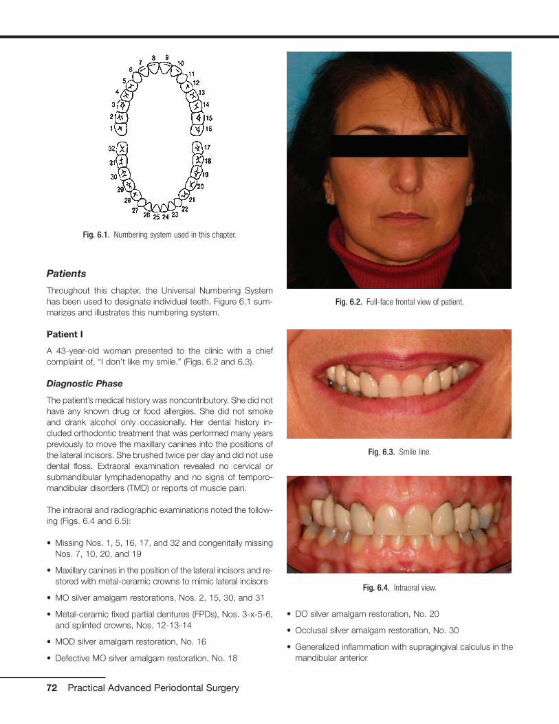
Patients
Throughout this chapter, the Universal Numbering Systemhas been used to designate individual teeth. Figure 6.1 sum-marizes and illustrates this numbering system.
Patient I
A 43-year-old woman presented to the clinic with a chiefcomplaint of, “I don’t like my smile.” (Figs. 6.2 and 6.3).
Diagnostic Phase
The patient’s medical history was noncontributory. She did nothave any known drug or food allergies. She did not smokeand drank alcohol only occasionally. Her dental history in-cluded orthodontic treatment that was performed many yearspreviously to move the maxillary canines into the positions ofthe lateral incisors. She brushed twice per day and did not usedental floss. Extraoral examination revealed no cervical orsubmandibular lymphadenopathy and no signs of temporo-mandibular disorders (TMD) or reports of muscle pain.
The intraoral and radiographic examinations noted the follow-ing (Figs. 6.4 and 6.5):
• Missing Nos. 1, 5, 16, 17, and 32 and congenitally missingNos. 7, 10, 20, and 19
• Maxillary canines in the position of the lateral incisors and re-stored with metal-ceramic crowns to mimic lateral incisors
• MO silver amalgam restorations, Nos. 2, 15, 30, and 31
• Metal-ceramic fixed partial dentures (FPDs), Nos. 3-x-5-6,and splinted crowns, Nos. 12-13-14
• MOD silver amalgam restoration, No. 16
• Defective MO silver amalgam restoration, No. 18
• DO silver amalgam restoration, No. 20
• Occlusal silver amalgam restoration, No. 30
• Generalized inflammation with supragingival calculus in themandibular anterior
72 Practical Advanced Periodontal Surgery
Fig. 6.1. Numbering system used in this chapter.
Fig. 6.2. Full-face frontal view of patient.
Fig. 6.3. Smile line.
Fig. 6.4. Intraoral view.
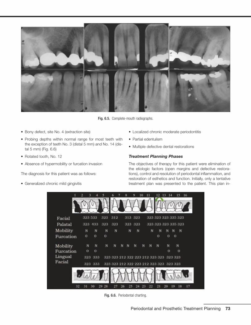
• Bony defect, site No. 4 (extraction site)
• Probing depths within normal range for most teeth with the exception of teeth No. 3 (distal 5 mm) and No. 14 (dis-tal 5 mm) (Fig. 6.6)
• Rotated tooth, No. 12
• Absence of hypermobility or furcation invasion
The diagnosis for this patient was as follows:
• Generalized chronic mild gingivitis
• Localized chronic moderate periodontitis
• Partial edentulism
• Multiple defective dental restorations
Treatment Planning Phases
The objectives of therapy for this patient were elimination ofthe etiologic factors (open margins and defective restora-tions), control and resolution of periodontal inflammation, andrestoration of esthetics and function. Initially, only a tentativetreatment plan was presented to the patient. This plan in-
Periodontal and Prosthetic Treatment Planning 73
Fig. 6.5. Complete-mouth radiographs.
Fig. 6.6. Periodontal charting.

cluded the removal of artificial crowns, evaluation of the re-storability of teeth, and plaque control measures.
Initial Periodontal Phase
This phase included scaling and root planing on the distalsurfaces of Nos. 3 and 14, oral hygiene instructions, andreevaluation of any pocket reduction and oral hygiene.
Provisional Phase
In the provisional phase, the defective fixed restorations wereremoved (Figs. 6.7 and 6.8) and replaced with physiologicallyand aesthetically acceptable provisional restorations.
In evaluating the gingival line in the maxillae, a gingival line dis-crepancy was noted that was caused by the pontic in the areaof No. 4. This discrepancy compromised the overall aesthetic
appearance and contributed to plaque accumulation. Therewas also a gingival line discrepancy between the central inci-sors and the lateral incisors because the lateral incisors wereoriginally canines that were orthodontically repositioned.
74 Practical Advanced Periodontal Surgery
Fig. 6.7. A, Teeth Nos. 3, 5, and 6 after removal of defective restora-tions. B, Teeth after repreparation.
Fig. 6.9. Provisional restorations, Nos. 3-x-5, 6, 11, 12, and 13. Notethe gingival line discrepancies at sites Nos. 3-x-5, 8-9, and 11-12-13.
A
B
Fig. 6.8. A, Teeth Nos. 11, 12, and 13 after removal of defectiverestorations. B, Teeth after repreparation.
A
B

In addition, there was a gingival line discrepancy betweenNos. 11, 12, and 13 (Fig. 6.9). Based on these findings, a de-finitive treatment plan was presented to the patient. This planwas (Fig. 6.10) as follows:
• Soft tissue augmentation, area No. 4
• Microsurgical crown lengthening procedure, Nos. 8 and 9for aesthetic purposes
• Surgical crown-lengthening procedure, No. 13 for aes-thetic purposes
• Metal-ceramic FPD, No. 3-x-5
• Ceramic crowns, Nos. 6 and 11
• Porcelain laminate veneers, Nos. 8 and 9
• Metal-ceramic crowns, Nos. 12 and 13
Preprosthetic Periodontal Phase
Soft tissue inlay graft, site No. 4. A split-thickness flapwas elevated. Soft tissue augmentation for site No. 4 was ac-complished by using an autogenous connective tissue inlaygraft obtained from the patient’s palate. The graft was su-tured and secured to the periosteum. The flap was posi-tioned and sutured without tension. The tissue surface of thepontic was relieved in the area of the surgical site to preventtissue impingement. The pontic was relined 8 weeks aftersurgery with autopolymerizing acrylic resin (Coldpac; theMotloid Co., Chicago, IL, USA) to allow gentle pressure onthe graft to contour the soft tissue at the pontic site and de-velop an esthetic gingival line. The pontic was relined again 1week later to allow for additional contouring of the gingivalline (Fig. 6.11).
Periodontal and Prosthetic Treatment Planning 75
Fig. 6.10. Preprosthetic treatment plan: A, Soft tissue augmentation,area No. 4. B, Microsurgical crown-lengthening procedure, Nos. 8 and 9,for aesthetic purposes. C, Crown-lengthening procedure, No. 13, foraesthetic purposes.
A
B
C
Fig. 6.11. A, B, Soft tissue inlay graft site No. 4, preoperative view.
A
B
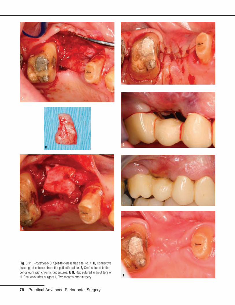
76 Practical Advanced Periodontal Surgery
C
E
F
G
H
I
D
Fig. 6.11. (continued) C, Split-thickness flap site No. 4. D, Connectivetissue graft obtained from the patient’s palate. E, Graft sutured to theperiosteum with chromic gut sutures. F, G, Flap sutured without tension.H, One week after surgery. I, Two months after surgery.

Surgical crown lengthening, No. 13. A submarginal inci-sion was made at the anticipated gingival line and a full-thickness flap was elevated. Ostectomy was performed toallow a 3-mm distance between the anticipated gingival lineand the crest of the alveolar bone (Rosenberg et al. 1980).
The flap was repositioned and sutured with 4-0 chromic gutsutures (Fig. 6.12).
Surgical crown lengthening, Nos. 8 and 9. Surgicalcrown lengthening was required for aesthetic reasons on thefacial surfaces of Nos. 8 and 9 only (Fig. 6.13).
Periodontal and Prosthetic Treatment Planning 77
Fig. 6.12. Surgical crown lengthening procedure tooth No. 13. A, Preoperative view. B, 3-mm distance allowed between anticipated finish line ofcrown preparation and alveolar crest. C, Site sutured with vertical mattress technique and 4-0 chromic gut sutures. D, Two weeks after surgery.
CA
B D
Fig. 6.13. Microsurgical crown-lengthening procedure for the facial surfaces of Nos. 8 and 9 to correct gingival line discrepancy. A, Preoperativeview. B, Vertical incisions at the line angles of Nos. 8 and 9 by using a microsurgical blade.
A B

To preserve the papillae and the soft tissue around Nos. 7and 10, a microsurgical crown-lengthening procedure was performed. There are many advantages of this techniquewhen compared with conventional surgical crown lengthen-ing procedures (Dibart and Karima 2006). This procedure
• Is less invasive
• Requires smaller incisions
• Allows greater precision when closing wounds
• Is less traumatic
• Is less painful postoperatively
• Allows faster healing and vascularization
• Produces more predictable results in areas with very thingingiva or in the “aesthetic zone”
Prosthetic Phase
Figure 6.14 is a wax replica of the proposed treatment plan.
Two months after completion of all periodontal surgical pro-cedures, the margins for all crown preparations were final-ized, and Nos. 8 and 9 were prepared for porcelain laminateveneers (Fig. 6.15).
New provisional restorations were fabricated, relined and ce-mented with temporary cement (Temp Bond; Kerr, Romulus,MI, USA) (Fig. 6.16).
78 Practical Advanced Periodontal Surgery
C
D
E
F
G
Fig. 6.13. (continued) C, Full-thickness flap elevated. D, Ostectomycompleted. E, Flaps sutured with 7-0 Vicryl sutures. F, One week aftersurgery. G, Two weeks after surgery.
Fig. 6.14. Wax replica of proposed treatment plan.

Periodontal and Prosthetic Treatment Planning 79
Fig. 6.15. Preparations for veneers, Nos. 8 and 9.
A C
DB
Fig. 6.16. Provisional restoration, Nos. 3-x-5-6-8-9-11-12-13. A, After contouring. B, In the mouth.
A B

One week later, a final impression was made with polyetherimpression material (Permadyne Penta L and ImpregumPenta; 3M ESPE, Seefeld, Germany) (Fig. 6.17).
A face-bow record was made and jaw relation records at MIPwere made. A definitive cast was fabricated, along with a castof the provisional restorations, and these casts were mountedin an articulator (Mark II Denar; Water Pik Technologies, Fort
Collins, CO, USA). The shade was selected (Vita B1) (VITAPANClassical Shade Guide; H Rauter GmbH & Co., Sackinggen,Germany). Porcelain laminate veneers for Nos. 8 and 9, zirco-nia copings for Nos. 6 and 11, metal copings for No. 12 and13, and a metal framework for No. 3-x-5 were made. All cop-ings and castings were tried in the mouth, and the fit was ver-ified with black and white silicone disclosing material (FitChecker; GC Corporation, Tokyo, Japan) (Fig. 6.18).
80 Practical Advanced Periodontal Surgery
Fig. 6.17. A, Gingival displacement cord in place. B, Final impression with polyether impression material.
A B
Fig. 6.18. Porcelain laminate veneers, Nos. 8 and 9, on cast (A) and bonded (B). C, Cast framework for FPD, Nos. 3-x-5, and zirconia coping, No. 6.D, Zirconia coping, No. 11, and castings for crowns, Nos. 12 and 13.
A C
DB

The veneers were luted with resin cement (Variolink II, IvoclarVitadent, Amherst, NY, USA). The provisional restorations for Nos. 3-x-5, 12, and 13 were recemented with Temp Bond cement. Because the resin luting agent requires an av-erage of 2 weeks for the shade to mature beneath the ve-neers, the final shade selection for the remaining restorationswas delayed. The final determination after 2 weeks was VitaA2 (Fig. 6.19).
At that stage, the application of porcelain to the remainder ofthe restorations was accomplished with Vita A2 porcelain.Restorations were glazed and the metal was polished. At theday of final delivery, provisional restorations were removed.A cleaning solution (Cavidry; Parkell, Farmingdale, NY, USA)was applied to all preparations to remove any oily residue,and clinical try-in of all restorations was completed. A resin-modified glass ionomer cement (Rely-X Luting; 3M ESPE)was used for final cementation of all restorations (Figs. 6.20
Periodontal and Prosthetic Treatment Planning 81
Fig. 6.19. Two weeks after cementation of veneers, shade was selected(Vita A2).
Fig. 6.20. A, Final restorations after porcelain application and glazing.B, Intraoral try-in. C, Corrected soft tissue profile Nos. 6, 8, 9, and 11.
A
B
C
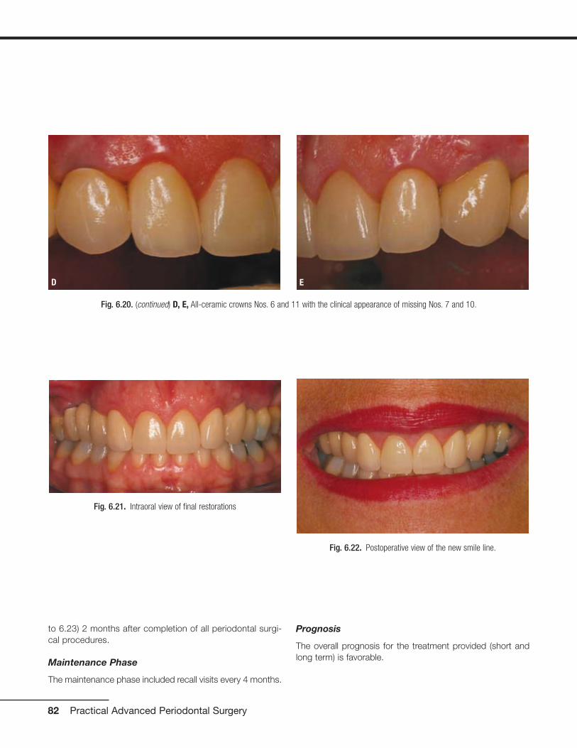
to 6.23) 2 months after completion of all periodontal surgi-cal procedures.
Maintenance Phase
The maintenance phase included recall visits every 4 months.
Prognosis
The overall prognosis for the treatment provided (short andlong term) is favorable.
82 Practical Advanced Periodontal Surgery
Fig. 6.20. (continued) D, E, All-ceramic crowns Nos. 6 and 11 with the clinical appearance of missing Nos. 7 and 10.
D E
Fig. 6.21. Intraoral view of final restorations
Fig. 6.22. Postoperative view of the new smile line.

Patient II
A 70-year-old man presented to the clinic with a chief com-plaint of, “I need some implants for my lower jaw. My otherdentist just finished all my upper teeth last year, and he sentme to you for the implants” (Fig. 6.24).
Diagnostic Phase
The patient’s medical history was noncontributory. He did nothave any known drug or food allergies. He had a previoushistory of smoking for 30 years, but for the past 3 years hehas been using a nicotine patch and nicotine supplementgum. He had been smoke-free since then. He drank alcoholoccasionally. His dental history included multiple extractionsand fixed restorations. Extra-oral examination revealed nocervical or submandibular lymphadenopathy and no signs ofTMD or reports of muscle pain.
Periodontal and Prosthetic Treatment Planning 83
Fig. 6.24. Full-face frontal view of patient.
Fig. 6.23. Before (A) and after (B) (full-face view). Before (C) and after (D) (close-up view).
A C
DB

The intraoral and radiographic examinations revealed the fol-lowing (Figs. 6.25 and 6.26):
• Missing, Nos. 1, 2, 3, 5, 14, 15, 16, 17, 19, 21, 23, 24, 25,26, 29, 30, and 32
• Metal-ceramic FPD, Nos. 4-x-6
• Metal-ceramic crowns, Nos. 7, 8, 9, 10, 11, 12, and 13
• Defective metal-ceramic FPD, 22-x-x-x-x-27-28
• MOD silver amalgam restorations, Nos. 18 and 31
• Inadequate endodontic therapy, No. 20 with defectiverestoration
• Normal probing depths (between 2-3 mm), without bleed-ing upon probing, except for No. 18 where the probingdepths were 6 mm on the mesial surface and 5 mm on thedistal surface
• No hypermobility of the teeth or furcation invasions, exceptfor No. 18, which had Class II hypermobility and Grade IIIfurcation invasion
Maxillary and mandibular alginate impressions were made,along with a face-bow transfer and centric jaw relationrecord. The diagnostic casts were mounted in a semiad-justable articulator.
The diagnosis for this patient was as follows:
• Generalized mild gingivitis with localized moderate peri-odontitis, No. 18
• Partial edentulism
• Recurrent dental caries
• Defective dental restorations
• Inadequate endodontic treatment
Treatment Planning Phases
The treatment plan for this patient included the following:
• Extraction of Nos. 18, 20 and 31
• Implant-supported metal-ceramic crowns, sites Nos. 19-20-21 (immediate implant placement for No. 20), and 29
• Replacement of the defective metal-ceramic FPD, Nos.22-x-x-x-x-27-28, to restore aesthetics and function
Initial Periodontal Phase
The initial periodontal phase included complete-mouth pro-phylaxis and oral hygiene instructions.
Preprosthetic Periodontal Phase
For the preprosthetic periodontal phase, a CT scan was pre-scribed and the proposed implant sites (Nos. 19, 20, 21, and29) were evaluated (Fig. 6.27).
84 Practical Advanced Periodontal Surgery
Fig. 6.25. Intraoral views. A, MIP. B, Maxillary arch. C, Mandibular arch.
A
B
C

Periodontal and Prosthetic Treatment Planning 85
Fig. 6.26. Complete-mouth radiographs.
Fig. 6.27. CT scan evaluation. A, Panoramic cut. B, Horizontal cut. C,Segmental cut.
A
B
C
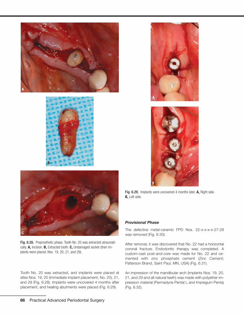
Tooth No. 20 was extracted, and implants were placed atsites Nos. 19, 20 (immediate implant placement, No. 20), 21,and 29 (Fig. 6.28). Implants were uncovered 4 months afterplacement, and healing abutments were placed (Fig. 6.29).
Provisional Phase
The defective metal-ceramic FPD Nos. 22-x-x-x-x-27-28was removed (Fig. 6.30).
After removal, it was discovered that No. 22 had a horizontalcoronal fracture. Endodontic therapy was completed. Acustom-cast post-and-core was made for No. 22 and ce-mented with zinc phosphate cement (Zinc Cement;Patterson Brand, Saint Paul, MN, USA) (Fig. 6.31).
An impression of the mandibular arch (implants Nos. 19, 20,21, and 29 and all natural teeth) was made with polyether im-pression material (Permadyne Pental L and Impregum Penta)(Fig. 6.32).
86 Practical Advanced Periodontal Surgery
Fig. 6.28. Preprosthetic phase. Tooth No. 20 was extracted atraumati-cally. A, Incision. B, Extracted tooth. C, Undamaged socket (then im-plants were placed, Nos. 19, 20, 21, and 29).
A
B
C
Fig. 6.29. Implants were uncovered 4 months later. A, Right side.B, Left side.
A
B

Periodontal and Prosthetic Treatment Planning 87
Fig. 6.30. A, Removal of defective FPD Nos. 22-x-x-x-x-27-28. B,Horizontal tooth fracture No. 22 was noted.
A
B
Fig. 6.32. Impression was made for fabrication of provisional restorations. A, Impression copings in place. B, Impression.
A B
Fig. 6.31. Cast post-and-core. A, Try-in. B, Delivery.
A
B

Alginate impression material (Jeltrate; Dentsply, Melford, DE,USA) was used for the maxillary arch. A face-bow transferwas made, and a centric jaw relation record was made forthe fabrication of the provisional restorations (Fig. 6.33).
The surgical mounts for the dental implants were prepared tobe used as provisional abutments (Fig. 6.34).
A wax replica of the proposed treatment plan was prepared,and the wax pattern was invested and heat processed toproduce an acrylic resin (Namilon; Justi, Oxnard, CA, USA)provisional restoration (Fig. 6.35).
The provisional FPD was cemented with Temp Bond cement(Fig. 6.36).
88 Practical Advanced Periodontal Surgery
Fig. 6.33. A, Face-bow transfer. B, Casts mounted in centric relation.
A B
Fig. 6.34. Surgical mounts (A, B) of the dental implants were prepared to be used as temporary abutments (C, D).
A
B
C
D

Periodontal and Prosthetic Treatment Planning 89
Fig. 6.35. A, Wax replica of the mandibular arch. B, Heat processed provisional restoration. C, D, Provisional restoration after reline and temporarycementation.
A
B
C
D
Fig. 6.36. Patient’s smile after provisional restorations were placed.

Prosthetic Phase
Two weeks later, the patient presented for definitive impres-sions with polyether impression material (Permadyne Pental Land Impregum Penta) (Fig. 6.37).
A centric jaw relation record was completed and themandibular cast was mounted. An alginate impression(Jeltrate) of the mandibular provisional restorations was madefor the dental laboratory technician to use as a guide in thefabrication of the final restorations (Fig. 6.38).
90 Practical Advanced Periodontal Surgery
Fig. 6.37. A, Final impression made with polyether impression material. B, Soft tissue replicas around implant analogs. C,D, E, Fixed bilateralmandibular record bases for centric relation record.
A
B
E
C
D

Periodontal and Prosthetic Treatment Planning 91
Fig. 6.38. A, Jaw relation record at centric relation with Lucia jig (Lucia, 1983) on anterior teeth and silicone registration material (Blu Mousse) on theposterior teeth. B, Lucia jig was then replaced with hard wax and relined with Temp Bond cement for stability of the casts during the mounting. C,Casts mounted. D, Diagnostic cast of existing mandibular provisional restoration was also mounted.
A
B
C
D

A clear plastic, vacuum-formed shell of the mandibular provi-sional restoration was also provided to the dental laboratorytechnician as a three-dimensional guide for the fabrication ofthe custom abutments (Fig. 6.39).
Metal castings and frameworks were fabricated. The fit of
all metal castings was verified with silicone disclosing mate-rial (Fit Checker). The selected shade was Vita A2 (Fig.6.40).
Metal castings and frameworks were returned to the dentallaboratory for porcelain application (Fig. 6.41). Canine guid-
92 Practical Advanced Periodontal Surgery
Fig. 6.39. A, B, Clear vacuum-formed shell of duplicate cast of patient’s provisional restoration to be used as a three-dimensional guide for fabrica-tion of custom abutments. C, D, Milled custom abutments.
A
B
C
D
A B
Fig. 6.40. A, Metal castings and frameworks. B, Metal try-in.

Periodontal and Prosthetic Treatment Planning 93
Fig. 6.40. (continued) C, Fit Checker silicone disclosing material to verify fit. D, Final shade was Vita A2.
C D
Fig. 6.41. Restorations after porcelain application. A, In occlusion. B, Frontal view. C, Occlusal view.
A
C
B

ance was established for the dynamic occlusal scheme (Fig.6.42). Final delivery of the fixed prostheses was completed byusing zinc phosphate cement (Zinc Cement) for the cemen-tation of the tooth-supported FPD and by using Temp Bondcement for the cementation of implant-supported restora-tions (Figs. 6.43 to 6.45).
Maintenance Phase
The maintenance phase included recall visits every 3 to 4months.
Prognosis
The overall prognosis for the treatment provided (short- andlong-term) is favorable.
Patient III
A 40-year-old woman presented to the clinic with a chiefcomplaint of, “I need new crowns, and I want a better smile”(Fig. 6.46).
Diagnostic Phase
The patient’s medical history was noncontributory. She didnot have any known drug or food allergies. She did notsmoke or drink alcohol. Her dental history included multipleextractions and multiple restorations performed outside ofthe United States in 2001. She brushed twice per day anddid not use dental floss. Extraoral examination revealed nocervical or submandibular lymphadenopathy and no signs ofTMD or reports of muscle pain.
94 Practical Advanced Periodontal Surgery
Fig. 6.43. Clinical try-in (A) and final delivery (B).
A B
Fig. 6.42. Canine guidance. A, Right side. B, Left side.
A B

Periodontal and Prosthetic Treatment Planning 95
Fig. 6.44. Intraoral view before (A) and after (B) treatment.
A B
Fig. 6.45. Patient’s smile after treatment. Fig. 6.46. Full-face frontal view of patient.

The intraoral and radiographic examinations noted the follow-ing (Figs. 6.47 and 6.48):
• Generalized redness, edema, and glazing of the gingiva,especially in the maxillary anterior sextant
• Missing, Nos. 1, 3, 5, 9, 13, 14, 17, 18, 19, 28, 30, and 32
• Multiple defective restorations, Nos. 2-x-4-x-6, Nos. 7-8-x-10, and Nos. x-29-x-31
• Endodontic therapy, Nos. 4, 7, 11, 29, and 31
• Periapical radiolucency, No. 29
• Inadequate endodontic therapy, No. 31
96 Practical Advanced Periodontal Surgery
Fig. 6.47. Intraoral view.
Fig. 6.48. Complete-mouth radiographs.

• Occlusal silver amalgam restoration, No. 16 with mesialand distobuccal carious lesions
• Mesial drift, Nos. 15 and 16
• Defective restorations, dental caries, and inadequate en-dodontic therapy, No. 20 and 21
• Distal carious lesions, Nos. 22 and 27
• Probing depths within the normal range (2 to 3 mm), ex-cept for teeth Nos. 4, 6, 10, 11, and 15, where probingdepths ranged between 4 and 5 mm (Fig. 6.49)
• Generalized bleeding upon probing
• No hypermobility or furcation invasions (Fig. 6.49)
• Multiple defective FPDs
• Multiple teeth with inadequate endodontic therapy
• Localized bone loss (10% to 15%), distal surface of No. 15and the mesial surface of No. 10 (Fig. 6.48)
Impressions were made with alginate (Jeltrate). Her diagnos-tic casts were mounted in centric relation in a semiadjustablearticulator with a face-bow record (Fig. 6.50).
The diagnosis for this patient was as follows:
• Generalized moderate chronic gingivitis
• Localized moderate chronic periodontitis, No. 15
• Partial edentulism
• Defective dental restorations
• Carious lesions
• Chronic periradicular periodontitis, No. 29
The etiologic factors contributing to this diagnosis were bac-terial plaque as the primary factor and previous dentistry andpatient neglect as secondary factors.
Treatment-Planning Phase
The objectives of therapy for this patient were elimination ofthe etiologic factors (open margins, overcontoured artificialcrowns, inadequate endodontic therapy, and dental caries),control and resolution of periodontal inflammation, andrestoration of aesthetics and function.
Periodontal and Prosthetic Treatment Planning 97
Fig. 6.50. Diagnostic casts.
Fig. 6.49. Periodontal charting.

Initially, only a tentative treatment plan could be presented tothe patient. This plan, according to the diagnostic waxing, in-cluded the following (Fig. 6.51):
• Removal of artificial crowns to evaluate the restorability ofthe teeth and to eliminate plaque retentive factors
• Extraction of No. 16
• Metal-ceramic FPDs, Nos. 2-x-4-x-6, 12-x-15, 27-x-29-x-31, and 8-x-10
• Metal-ceramic crowns, Nos. 7, 11, 20, and 21
• Endodontic retreatment, cast posts-and-cores, and metal-ceramic crowns, Nos. 7, 20, 21, 29, and 31
Initial Periodontal Phase
This phase included complete-mouth dental prophylaxis withscaling and root planning on the distal surface of No. 15, oralhygiene instructions, reevaluation of oral hygiene and pocketreduction, 3 to 4 weeks after the initial therapy.
Provisional Phase
The purpose of the provisional phase was the elimination ofthe etiologic factors and the maintenance of the health of thetreated periodontium. The defective fixed restorations wereremoved and caries control was completed to evaluate theremaining teeth and determine their restorability and progno-sis. At this stage, it was determined that all of her abutmentteeth were restorable except for No. 4. Tooth No. 4 was com-promised because of limited remaining tooth structure anddeep subgingival margins (Fig. 6.52).
A crown-lengthening procedure would lead to furcation ex-posure and an unfavorable crown-to-root ratio. The recom-mended treatment was extraction of No. 4 and replacementwith an implant-supported metal-ceramic crown. Caries con-
trol and temporization for teeth Nos. 20 and 21 were com-pleted. Evaluation of the abutments indicated that surgicalcrown lengthening was required in the interproximal area be-tween Nos. 20 and 21 (Fig. 6.53).
As a result of meticulous oral hygiene and replacement of thedefective fixed restorations with physiologically and estheti-cally acceptable provisional restorations, the tissue health im-proved within 2 weeks, and the patient was satisfied with herappearance (Fig. 6.54). A gingival line discrepancy was notedbetween Nos. 8 and 9 (Fig. 6.55).
98 Practical Advanced Periodontal Surgery
Fig. 6.51. Wax replica of tentative treatment plan.
Fig. 6.52. A, B, Defective fixed restorations were removed. Note thecompromised remaining tooth structure on No. 4 (C).
A
B
C
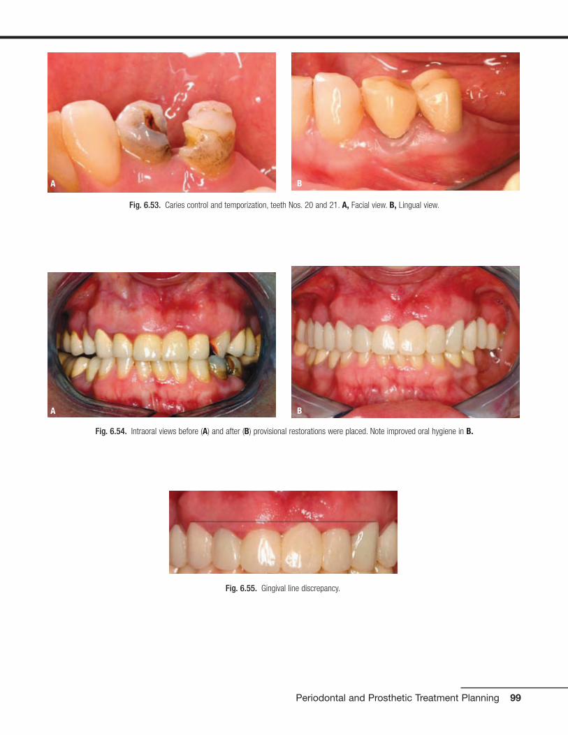
Periodontal and Prosthetic Treatment Planning 99
Fig. 6.55. Gingival line discrepancy.
Fig. 6.53. Caries control and temporization, teeth Nos. 20 and 21. A, Facial view. B, Lingual view.
A B
Fig. 6.54. Intraoral views before (A) and after (B) provisional restorations were placed. Note improved oral hygiene in B.
A B

At this stage, the definitive treatment plan was presented tothe patient (Figs. 6.56 and 6.57).
The treatment plan consisted of the following:
• Extraction of No. 16
• Metal-ceramic FPD, Nos. 8-x-10, 12-x-15
• Metal-ceramic crowns, Nos. 2, 6, 11, 20, 21, and 27
• Implant-supported metal-ceramic crowns, Nos. 3-4-5, 18-19, 28, and 31
• Surgical crown-lengthening procedure, Nos. 6 to 11
• Endodontic retreatment, cast posts-and-cores, and metal-ceramic crowns, Nos. 7, 20, 21, 29, and 31
The patient accepted the proposed treatment plan for themaxillae, but because of financial constraints, she acceptedan alternative treatment plan for the mandible that includedthe following:
• Endodontic retreatment, Nos. 20, 21, 29, and 31
• Metal-ceramic crowns, Nos. 20 and 21
• Metal-ceramic FPD, Nos. 27-x-29-x-31
100 Practical Advanced Periodontal Surgery
Fig. 6.57. Wax replica of finalized treatment plan for mandibular arch.
Fig. 6.56. Wax replica of finalized treatment plan for maxillary arch.
Fig. 6.58. Crown lengthening for the anterior sextant to gain crownlength and for aesthetic purposes (A) with the use of a surgical guidetemplate to assist the periodontist (B).
A
B

Preprosthetic Periodontal Phase
After the definitive treatment plan was presented to the pa-tient, the patient entered phase III of the treatment, whichwas the pre-prosthetic periodontal phase. This phase beganwith surgical crown lengthening in the anterior sextant to ob-tain more crown length and to improve esthetics. A surgicalguide was used (Fig. 6.58).
A full-thickness flap was elevated and ostectomy was per-formed to obtain a 3-mm distance between the anticipated
gingival line Pas displayed in the template and the osseouscrest, allowing space for the supracrestal gingival tissues.The flap was placed at the desired position and sutured witha vertical mattress technique by using 4-0 chromic gut su-tures (Fig. 6.59).
After crown-lengthening procedures, a minimal healingperiod of 6 weeks was required before repreparation of theteeth and relining of the provisional restorations because 12 days are required for the junctional epithelium to form,
Periodontal and Prosthetic Treatment Planning 101
Fig. 6.59. Crown-lengthening procedure for teeth Nos. 6–11. A, Preoperative view. B, Full-thickness flap elevated and ostectomy performed. C,Closure with 4-0 chromic gut sutures. D, One week after surgery.
A
B
C
D

but the lamina propria is not completely formed until 6weeks (Listgarten 1972) (Fig. 6.60). This patient also re-quired a surgical crown lengthening procedure for Nos. 20and 21. This procedure was required primarily in the inter-proximal area to ensure sufficient height of tooth structureto develop an acceptable ferrule effect. After flap elevation,ostectomy was completed, and the area was sutured with
a vertical mattress technique and 4-0 chromic gut sutures(Fig. 6.61).
The last phase of the preprosthetic periodontal phase wasthe implant phase for sites Nos. 3, 4, and 5. For this phase,the patient was referred for a CT scan with a dual-purposetemplate (Fig. 6.62).
102 Practical Advanced Periodontal Surgery
Fig. 6.60. Intraoral view before (A) and after (B) surgery. Smile before (C) and after (D) surgery.
A
B
C
D
Fig. 6.61. Crown-lengthening procedure for teeth Nos. 20 and 21. A, Preoperative. B, Provisional crowns removed.
A B

Periodontal and Prosthetic Treatment Planning 103
Fig. 6.61. (continued) C, Incision. D, Suturing. E, After suture removal.
C D
E
Fig. 6.62. Dual-purpose template for implants Nos. 3, 4, and 5.

The CT scan was evaluated for the selection of the size of theimplants (Fig. 6.63).
For site No. 3, the available bone width was 5 mm and theheight was 4 mm. The implant size planned for this site was4 mm � 11.5 mm. Because of the location of the maxillarysinus and the width of the bone, the treatment plan for thissite included a sinus floor elevation along with buccal aug-mentation of the residual alveolar bone with demineralizedfreeze-dried bone allograft (DFDBA; ACE Surgical, Brockton,MA, USA) and bovine bone (Bio-Oss; Osteohealth, Shirley,VA, USA).
For site No. 5, the available bone width was 5 mm and theheight was 15 mm. The implant size planned for this site was3.75 mm � 13 mm. Placing this implant according to the sur-gical guide would result in a thin buccal plate that is primarilycomposed of cortical bone; therefore, the recommendedtreatment included buccal augmentation with DFDBA (ACEsurgical) and bovine bone (Bio-Oss).
A full-thickness flap was elevated, and tooth No. 4 was ex-tracted. In evaluating the ridge at sites Nos. 3 and 5, Seibert’sClass I ridge defect was noted (a defect in the buccolingualdirection) (Seibert 1983) (Fig. 6.64).
104 Practical Advanced Periodontal Surgery
Fig. 6.63. CT scan evaluation for the implants. A, Panoramic cut. Thesegmental cuts. B, No. 3. C, No. 4. D, No. 5.
A
B C
D
Fig. 6.64. Extraction of tooth No. 4. Note the Seibert’s Class I ridgedefect. A, Incision. B, Socket. C, Tooth sectioned and removed in twopieces.
A
B
C

Sinus floor elevation for the site was accomplished by using thelateral window approach. The sinus membrane was elevated toreceive an implant 11.5 mm in length. The sinus was graftedwith DFDBA (Ace Surgical), bovine bone (Bio-Oss), and autoge-nous bone obtained from the palatal aspect of the surgical site.After the sinus was elevated and grafted, guided bone regener-ation for sites Nos. 3, 4, and 5 was completed. The first step inaccomplishing guided bone regeneration was decortication ofthe site with a No. 1 round carbide bur to increase the blood
supply to the graft material. After decortication (Buser et al.1990, 1996), the site was grafted with DFDBA (ACE surgical)and bovine bone (Bio-Oss). A resorbable membrane (Osteohealth)was used to protect and contain the graft material (Fig. 6.65).
The surgical area was closed without tension, and the ponticof the provisional FPD was trimmed away from the tissue toavoid irritation and facilitate plaque control. Another CT scanwas made 9 months after surgery to determine the bone
Periodontal and Prosthetic Treatment Planning 105
Fig. 6.65. Sinus floor elevation and guided bone regeneration. A,Lateral window approach performed and sinus membrane elevated. B,Sinus augmented with DFDB, Bio-Oss bovine bone, and autogenousbone. C, Decortication of buccal plate for ridge augmentation. D, Sitegrafted with DFDBA and Bio-Oss bovine bone. E, Resorbable membraneplaced. F, Closure with 4-0 Vicryl sutures.
A B
C
D
E
F

106 Practical Advanced Periodontal Surgery
Fig. 6.66. CT scan evaluation after sinus floor elevation (A). Note thegain in the vertical height (B and C) and the gain in horizontal width (D).
A
B C
D
Fig. 6.67. Implant placement sites Nos. 3, 4, and 5. A, Full-thickness flap elevated. B, The provisional restoration used as a surgical guide. C,Osteotomy sites. D, Implants placed.
A
B
C
D

width and height in preparation for implant placement afterthe sinus elevation and grafting procedure (Fig. 6.66).
A full-thickness flap was elevated. The patient’s provisionalrestoration was used as a surgical guide to place the implants.The flap was repositioned and sutured with 4-0 chromic gutsutures (Fig. 6.67).
Prosthetic Phase
The implants were uncovered six months after placement(Fig. 6.68). The provisional restoration was relined over thehealing abutments 4 weeks after uncovering (Fig. 6.69).
Four weeks later, final impressions of all teeth and implantswere made with polyether impression material (Permadyne
Periodontal and Prosthetic Treatment Planning 107
Fig. 6.68. Uncovering of implants. A, B, Implants uncovered 6 months after implant surgery. C, D, Tissue healing, 4 weeks after uncovering. Note for-mation of papillae.
A
B
C
D
A B
Fig. 6.69. Provisional restoration relined 4 weeks after uncovering. A, Intaglio surface. B, Provisional restoration in the mouth.

Penta L and Impregum Penta) and plastic stock trays (CoeSpacer Trays, Disposable Plastic Trays: GC America Inc.,Alsip, IL, USA) (Fig. 6.70). A face-bow transfer and centricjaw relation record were made for the mounting of the defin-itive cast and for the cross mounting with the cast of the pro-visional restorations. A jig described by Lucia (Lucia 1983)was used as an anterior stop and extra-hard baseplate wax(Tru Wax; Dentsply, York, PA, USA) was used to make the
record on the posterior teeth (Fig. 6.71). The definitive castand the cast of the provisional restorations were mountedand cross-mounted (Fig. 6.72).
Die relief was placed on the dies (Die Spacer; PattersonBrand), and an artificial acrylic resin tooth (Pilkington Turner 30-degree tooth, 230 LS; Dentsply) was arranged to replace No.19 at a height equal to half the height of the retromolar pad.
108 Practical Advanced Periodontal Surgery
Fig. 6.70. Final impression of all teeth and implants. A, B, Gingival displacement cords. C, D, Impressions.
A
B
C
D

Periodontal and Prosthetic Treatment Planning 109
Fig. 6.72. Definitive casts mounted and cross mounted with the provi-sional restorations. A, Definitive cast against definitive cast. B, Definitivecast against cast of provisional restorations. C, Cast of provisionalrestorations against definitive cast. D, Cast of provisional restorationsagainst cast of provisional restorations.
A
B
C
D
Fig. 6.71. Face-bow transfer (A) and centric jaw relation record (B, C)by using a Lucia jig on the anterior teeth and extra-hard baseplate waxon the posterior teeth.
A
B
C

(Fig. 6.73). A putty (Exaflex Putty; GC America Inc.) index of theprovisional restorations was made to provide a three-dimensionalview of the available space to the dental laboratory technician forthe fabrication of the custom abutments (Fig. 6.74).
A clinical try-in was accomplished to verify the position of thecustom abutments by using a verification jig fabricated fromlight polymerizing urethane dimethacrylate resin (Triad Tru
Tray VLC Custom Impression Tray Material; Dentsply) on thedefinitive cast (Fig. 6.75). At try in, it was noted that the cus-tom abutment for No. 4 was rotated on the cast. The verifi-cation jig was relieved in the area of No. 4, and autopolymer-izing resin material (Pattern resin LS: GC America Inc.) wasused to reline and re-register the position of the custom abut-ment in the mouth. This relationship was then transferred tothe definitive cast by altering the cast (Fig. 6.76).
110 Practical Advanced Periodontal Surgery
Fig. 6.73. A, Die relief placed on dies. B, Acrylic resin artificial tooth placed in position of No. 19 to establish occlusal plane at a height equal to halfthe height of the retromolar pad (marked in red).
A B
Fig. 6.74. Putty index of the provisional restoration was made to providea three-dimensional view of the available space for custom abutmentsfor implants. A, Facial view. B, C, Proximal views.
A C
B

Periodontal and Prosthetic Treatment Planning 111
Fig. 6.75. A, Custom abutments were fabricated. B, C, Verification jigwas made.
A
C
B
Fig. 6.76. A, Try-in of custom abutments. B, Verification jig indicatedthat custom abutment for No. 4 was malpositioned. Jig was hollowed outin area of No. 4. C, Autopolymerizing acrylic resin was used to registercorrect position of custom abutment. D, Position was transferred todefinitive cast, and cast was altered. Note pink stone where cast wasaltered (arrows).
A
B
C
D

Metal castings and frameworks were fabricated. The cast-ings were tried in the mouth, and the fit was verified with a sil-icone disclosing material (Fit Checker). The framework wassectioned between Nos. 3-4 and 4-5 and then soldered (Fig.6.77). The soldered casting for Nos. 3-4-5 was tried again inthe mouth, and the fit was verified.
A second jaw relation record was made at the desired VDOwith the use of a Lucia jig as an anterior stop and extra-hardbaseplate wax (Tru Wax; Dentsply) on the posterior teeth. Apick-up impression was made of the metal castings with theuse of polyether impression material (Permadyne Penta L andImpregum Penta). The casts were mounted and sent to thedental laboratory for porcelain application (Fig. 6.78). Theshade selected was Vita B1, as per the patient’s request.
At the porcelain bisque try-in, modifications to proximal and occlusal contacts were made. Some adjustments were
made also to the contours of the restorations. Canine guid-ance was established. The restorations were then sent forfinal glazing. At the day of final delivery, gold screws for the custom abutments Nos. 3, 4, and 5 were torqued to 32 N•cm with a torque wrench (Torque Indicator; 3I, Palm Beach Gardens, FL, USA). The abutments were then torqued again to 32 N•cm after a 10-minute waitingperiod to compensate for embedment relaxation of thescrews.
All restorations were cemented with Rely-X Luting resin-modified glass ionomer cement, with the exception of theimplant-supported restorations Nos. 3-4-5, which were ce-mented with temporary cement (Temp Bond) after sealing thescrew holes with a temporary sealer (Dura-Seal; Reliance,Worth, IL, USA). Temporary cement was used for the im-plant-supported restorations to ensure retrievability (Figs.6.79 and 6.80).
112 Practical Advanced Periodontal Surgery
Fig. 6.77. A, Metal castings and frameworks were fabricated. B, Castings were tried in the mouth. C, Fit verified with silicone disclosing material (FitChecker). D, Metal framework for implant-supported splinted crowns, Nos. 3–5, was sectioned, and reconnected with autopolymerizing acrylic resin inpreparation for soldering.
A
B
C
D
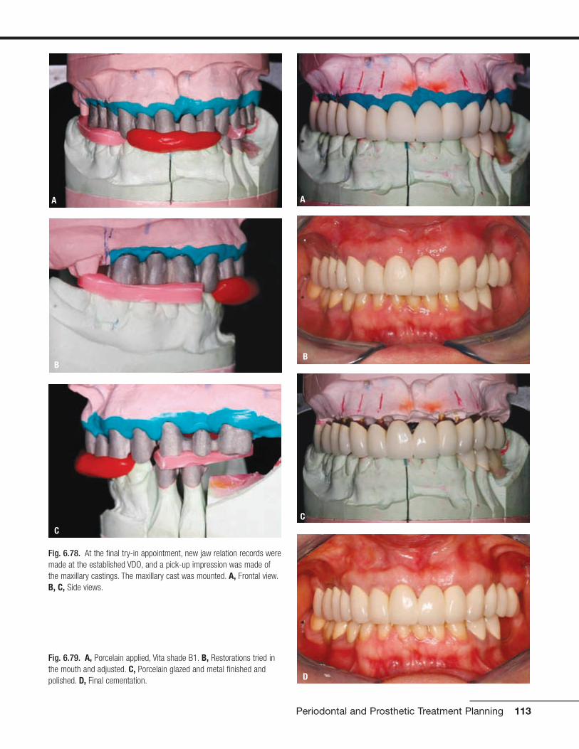
Periodontal and Prosthetic Treatment Planning 113
Fig. 6.78. At the final try-in appointment, new jaw relation records weremade at the established VDO, and a pick-up impression was made ofthe maxillary castings. The maxillary cast was mounted. A, Frontal view.B, C, Side views.
A
C
B
Fig. 6.79. A, Porcelain applied, Vita shade B1. B, Restorations tried inthe mouth and adjusted. C, Porcelain glazed and metal finished andpolished. D, Final cementation.
A
B
C
D

Maintenance Phase
The maintenance phase included recall visits every 3 to 4months.
Prognosis
The overall prognosis for the treatment provided (short andlong term) is favorable.
CONCLUSION
The overall quality of dental care depends on a concerted ef-fort among the various dentists involved, a thorough andcomplete diagnosis that addresses all disease processes,and a realistic, carefully sequenced treatment plan that offersa favorable prognosis.
REFERENCESAAP position paper. Periodontal considerations in the management of
cancer patients. Committee on Research, Science and Therapy ofthe American Academy of Periodontology. 1997. J. Periodontol.68:791–801.
Becker, W., L. Berg, and B. Becker. 1984. The long-term evaluation ofperiodontal treatment and maintenance in 95 patients. Int. J.Periodont. Restor. Dent. 2:55–72.
Buser, D., U. Bragger, N.P. Lang, et al. 1990. Regeneration and enlarge-ment of jaw bone using guided tissue regeneration. Clin. OralImplants Res. 1:22–32.
Buser, D., K. Dula, H.P. Hirt, et al. 1996. Lateral ridge augmentationusing autografts and barrier membranes: A clinical study with 40 par-tially edentulous patients. J. Oral Maxillofac. Surg. 54:420–432.
Chase, R., Jr., and S.B. Low. 1993. Survival characteristics of periodontally-involved teeth: a 40-year study. J. Periodontol. 64:701–705.
Davies, R. 1993. Antibiotic prophylaxis in dental practice. Br. Med. J.307:1210–1211.
Dibart, S, and M. Karima. 2006. Practical Periodontal Plastic Surgery.Ames, IA, Blackwell Publishing.
Flocken, J.E. 1980. Electrosurgical management of soft tissues inrestorative dentistry. Dent. Clin. North Am. 24:247–269.
Glickman, I. 1958. Clinical Periodontology, 2nd ed. Philadelphia, W.B.Saunders, pp. 694–696.
114 Practical Advanced Periodontal Surgery
Fig. 6.80. Intraoral views before (A) and after (B). Smile before (C) and after (D).
A B
C D
Listgarten, M.A. 1972. Normal development, structure, physiology andrepair of gingival epithelium. Oral Sci. Rev. 1:3–67.
Listgarten, M.A. 1972. Ultrastructure of the dento-gingival junction aftergingivectomy. J. Periodont. Res. 7:151–160.
Lucia, V.O. 1983. Modern Gnathological Concepts—Updated. Chicago,Quintessence, pp. 83–107.
McGuire, M. 1991. Prognosis versus actual outcome: a long-term surveyof 100 treated periodontal patients under maintenance care. J.Periodontol. 62:51–58.
Mealey, B.L., and T.W. Oates. 2006. Diabetes mellitus and periodontaldiseases. J. Periodontol. 77:1289–1303.
Miller, S.C. Textbook of Periodontia, 3rd ed. Philadelphia, Blackstone,1950, p. 125.
Morgano, S.M., P.M. Garvin, B.L. Muzynski, and W.F. Malone. 1989.Diagnosis and treatment planning. In W.F. Malone, D.L. Koth, E.Cavazos Jr., D.A. Kaiser, and S.M. Morgano, editors. Tylman’sTheory and Practice of Fixed Prosthodontics, 8th ed. St Louis,Ishiyaku EuroAmerica, pp. 1–23.
Morgano, S.M., and S.E. Brackett. 1999. Foundation restorations infixed prosthodontics: current knowledge and future needs. J.Prosthet. Dent. 82:643–657.
Rosenberg, E.S., D.A. Garger, and C.I. Evian. 1980. Tooth lengtheningprocedures. Compend. Cont. Educ. Dent. 1:161–173.
Seibert, J. 1983. Reconstruction of deformed, partially edentulousridges, using full thickness onlay grafts. Part I. Technique and woundhealing. Compend. Cont. Educ. Dent. 4:437–453.
Soileau, K.M. 2006. Oral post-surgical complications following the ad-ministration of bisphosphonates given for osteopenia related to ma-lignancy. J. Periodontol. 77:738–743.
Thomson, W.M., H.P. Lawrence, J.M. Broadbent, and R. Poulton 2006.The impact of xerostomia on oral-health-related quality of life amongyounger adults. Health and quality of life outcomes. 4:86 (publishedonline before print November 8, 2006).
Wooltorton, E. 2005. Health and Drug Alerts: Patients receiving intra-venous bisphosphonates should avoid invasive dental procedures.Can. Med. Assoc. J. 172:1684.
Periodontal and Prosthetic Treatment Planning 115
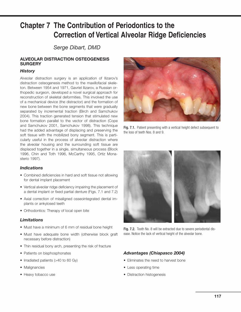
ALVEOLAR DISTRACTION OSTEOGENESISSURGERY
History
Alveolar distraction surgery is an application of Ilizarov’sdistraction osteogenesis method to the maxillofacial skele-ton. Between 1954 and 1971, Gavriel Ilizarov, a Russian or-thopedic surgeon, developed a novel surgical approach forreconstruction of skeletal deformities. This involved the useof a mechanical device (the distractor) and the formation ofnew bone between the bone segments that were graduallyseparated by incremental traction (Birch and Samchukov2004). This traction generated tension that stimulated newbone formation parallel to the vector of distraction (Copeand Samchukov 2001, Samchukov 1998). This techniquehad the added advantage of displacing and preserving thesoft tissue with the mobilized bony segment. This is parti-cularly useful in the process of alveolar distraction where the alveolar housing and the surrounding soft tissue aredisplaced together in a single, simultaneous process (Block1996, Chin and Toth 1996, McCarthy 1995, Ortiz Mona-sterio 1997).
Indications
• Combined deficiencies in hard and soft tissue not allowingfor dental implant placement
• Vertical alveolar ridge deficiency impairing the placement ofa dental implant or fixed partial denture (Figs. 7.1 and 7.2)
• Axial correction of misaligned osseointegrated dental im-plants or ankylosed teeth
• Orthodontics: Therapy of local open bite
Limitations
• Must have a minimum of 6 mm of residual bone height
• Must have adequate bone width (otherwise block graftnecessary before distraction)
• Thin residual bony arch, presenting the risk of fracture
• Patients on bisphosphonates
• Irradiated patients (>40 to 60 Gy)
• Malignancies
• Heavy tobacco use
Advantages (Chiapasco 2004)
• Eliminates the need to harvest bone
• Less operating time
• Distraction histogenesis
117
Chapter 7 The Contribution of Periodontics to the Correction of Vertical Alveolar Ridge Deficiencies
Serge Dibart, DMD
Fig. 7.1. Patient presenting with a vertical height defect subsequent tothe loss of teeth Nos. 8 and 9.
Fig. 7.2. Tooth No. 8 will be extracted due to severe periodontal dis-ease. Notice the lack of vertical height of the alveolar bone.

• Lower risk of morbidity of the surgical site
• Crestal part of the distracted segment has lower risk ofresorption
• Greater vertical bone gain
Armamentarium
• Standard surgical kit, as described in Practical PeriodontalPlastic Surgery plus:
• Alveolar Distraction Track Plus Kit (KLS Martin, Jackson-ville, FL, USA) and oscillating and sagittal microsaws (KLSMartin, Jacksonville, FL, USA)
Technique for the Anterior Segment
After proper local anesthesia (infiltration with xylocaine 2%with 1:100,000 epinephrine and 1:50,000 epinephrine for he-mostasis), an incision is made in the vestibule using a No. 15blade. The incision is made high enough in the mucosa toallow for proper mobilization of the flap (Fig. 7.3). The incisionmay be done in two steps: incision of the mucosal layer first,then incision of the connective tissue, muscles, and peri-osteum. Keep the blade oriented toward the alveolar bone.The incision has to be long enough to allow for easy bluntdissection with a periosteal elevator.
The role of the elevator is to now reflect the flap all the wayup to the alveolar crest of the edentulous site but not beyond(Figs. 7.4 and 7.5). It is critical to leave the palatal or lingualperiosteum attached to the bone, because it will be the onlysource of vascularization of the bony fragment during the dis-traction process. Once the bony area is exposed, it is usefulto draw a picture of the segment to be distracted on the boneusing a sterile No. 2 pencil (Fig. 7.6). The base of the bonysegment should be wider at the crest than apically (Fig. 7.7)to allow for unimpaired sliding movement during the traction
118 Practical Advanced Periodontal Surgery
Fig. 7.3. The incision is high up in the vestibule to allow for flap mobi-lization and access.
Fig. 7.4. The full-thickness flap is reflected using a periosteal elevator.
Fig. 7.5. Reflection stops at the alveolar crest.
Fig. 7.6. The segment to be distracted is delineated with a sterile No. 2pencil.

process. Also at this point, it is important to remember thatthe distracted segment should be no shorter than 5 mm.
Once the segment is visualized, it is time to adapt the distrac-tor to fit the clinical picture. This is the most time-consumingpart of the operation, because one has to adapt (cut) andbend the upper and lower arms of the distractor to fit the un-derlying bone architecture, while preserving the proper direc-tion of the vector (Figs. 7.8 to 7.10). Distractors are availablein 6-, 9-, 12-, and 15-mm lengths. After predrilling one holefor each arm while holding the distractor in place, the sagittalsaw (set at 20,000 RPM) is used to cut the bone (Fig. 7.11).It is better not to do a through-and-through cut at the begin-ning but to get as close as possible to the palatal/lingual bony
Alveolar Distraction Osteogenesis 119
Fig. 7.7. The segment to be cut is drawn on the bone. Notice the diver-gence of the cuts that will allow for free movement of the segment.
Fig. 7.10. One hole in each arm of the distractor is predrilled; this willallow accurate repositioning of the device.
Fig. 7.11. Using the oscillating microsaw (KLS Martin, Jacksonville, FL,USA), the osteotomy is started.
Fig. 7.8. The distractor is modified to fit the clinical picture.
Fig. 7.9. The distractor is placed, verifying the correct direction of thedistraction vector.
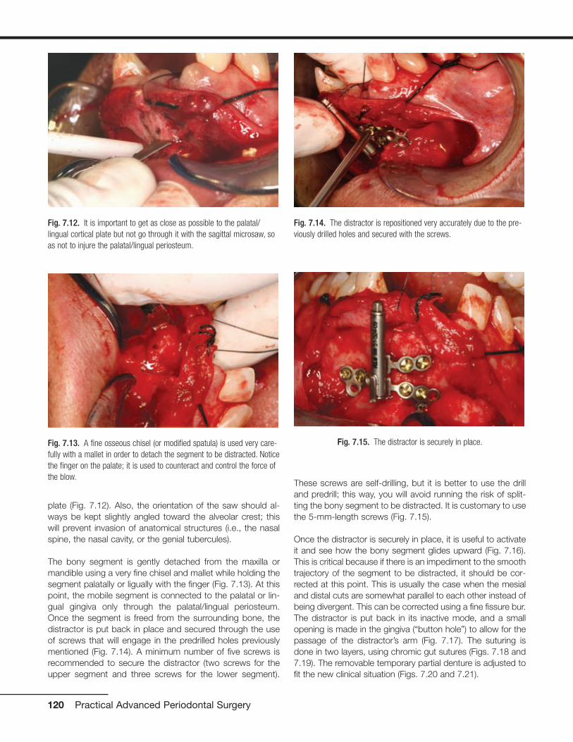
plate (Fig. 7.12). Also, the orientation of the saw should al-ways be kept slightly angled toward the alveolar crest; thiswill prevent invasion of anatomical structures (i.e., the nasalspine, the nasal cavity, or the genial tubercules).
The bony segment is gently detached from the maxilla ormandible using a very fine chisel and mallet while holding thesegment palatally or ligually with the finger (Fig. 7.13). At thispoint, the mobile segment is connected to the palatal or lin-gual gingiva only through the palatal/lingual periosteum.Once the segment is freed from the surrounding bone, thedistractor is put back in place and secured through the useof screws that will engage in the predrilled holes previouslymentioned (Fig. 7.14). A minimum number of five screws isrecommended to secure the distractor (two screws for theupper segment and three screws for the lower segment).
These screws are self-drilling, but it is better to use the drilland predrill; this way, you will avoid running the risk of split-ting the bony segment to be distracted. It is customary to usethe 5-mm-length screws (Fig. 7.15).
Once the distractor is securely in place, it is useful to activateit and see how the bony segment glides upward (Fig. 7.16).This is critical because if there is an impediment to the smoothtrajectory of the segment to be distracted, it should be cor-rected at this point. This is usually the case when the mesialand distal cuts are somewhat parallel to each other instead ofbeing divergent. This can be corrected using a fine fissure bur.The distractor is put back in its inactive mode, and a smallopening is made in the gingiva (“button hole”) to allow for thepassage of the distractor’s arm (Fig. 7.17). The suturing isdone in two layers, using chromic gut sutures (Figs. 7.18 and7.19). The removable temporary partial denture is adjusted tofit the new clinical situation (Figs. 7.20 and 7.21).
120 Practical Advanced Periodontal Surgery
Fig. 7.12. It is important to get as close as possible to the palatal/lingual cortical plate but not go through it with the sagittal microsaw, soas not to injure the palatal/lingual periosteum.
Fig. 7.13. A fine osseous chisel (or modified spatula) is used very care-fully with a mallet in order to detach the segment to be distracted. Noticethe finger on the palate; it is used to counteract and control the force ofthe blow.
Fig. 7.14. The distractor is repositioned very accurately due to the pre-viously drilled holes and secured with the screws.
Fig. 7.15. The distractor is securely in place.
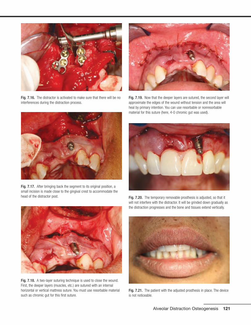
Alveolar Distraction Osteogenesis 121
Fig. 7.16. The distractor is activated to make sure that there will be nointerferences during the distraction process.
Fig. 7.17. After bringing back the segment to its original position, asmall incision is made close to the gingival crest to accommodate thehead of the distractor post.
Fig. 7.18. A two-layer suturing technique is used to close the wound.First, the deeper layers (muscles, etc.) are sutured with an internalhorizontal or vertical mattress suture. You must use resorbable materialsuch as chromic gut for this first suture.
Fig. 7.19. Now that the deeper layers are sutured, the second layer willapproximate the edges of the wound without tension and the area willheal by primary intention. You can use resorbable or nonresorbablematerial for this suture (here, 4-0 chromic gut was used).
Fig. 7.21. The patient with the adjusted prosthesis in place. The deviceis not noticeable.
Fig. 7.20. The temporary removable prosthesis is adjusted, so that itwill not interfere with the distractor. It will be grinded down gradually asthe distraction progresses and the bone and tissues extend vertically.
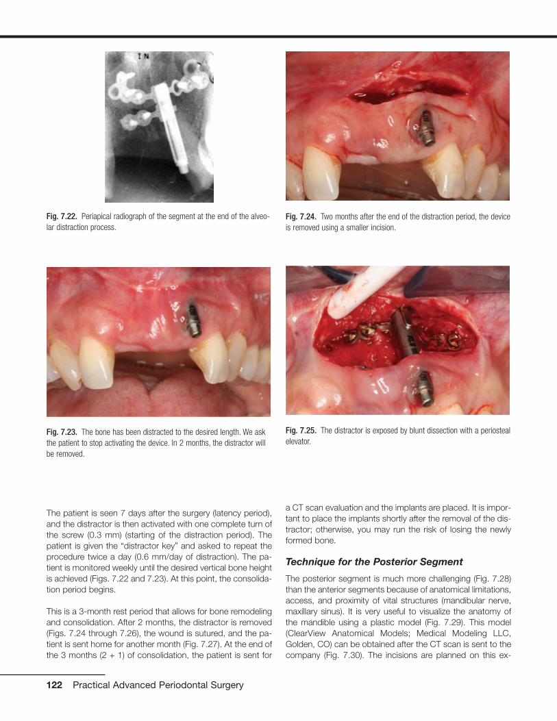
The patient is seen 7 days after the surgery (latency period),and the distractor is then activated with one complete turn ofthe screw (0.3 mm) (starting of the distraction period). Thepatient is given the “distractor key” and asked to repeat theprocedure twice a day (0.6 mm/day of distraction). The pa-tient is monitored weekly until the desired vertical bone heightis achieved (Figs. 7.22 and 7.23). At this point, the consolida-tion period begins.
This is a 3-month rest period that allows for bone remodelingand consolidation. After 2 months, the distractor is removed(Figs. 7.24 through 7.26), the wound is sutured, and the pa-tient is sent home for another month (Fig. 7.27). At the end ofthe 3 months (2 + 1) of consolidation, the patient is sent for
a CT scan evaluation and the implants are placed. It is impor-tant to place the implants shortly after the removal of the dis-tractor; otherwise, you may run the risk of losing the newlyformed bone.
Technique for the Posterior Segment
The posterior segment is much more challenging (Fig. 7.28)than the anterior segments because of anatomical limitations,access, and proximity of vital structures (mandibular nerve,maxillary sinus). It is very useful to visualize the anatomy ofthe mandible using a plastic model (Fig. 7.29). This model(ClearView Anatomical Models; Medical Modeling LLC,Golden, CO) can be obtained after the CT scan is sent to thecompany (Fig. 7.30). The incisions are planned on this ex-
122 Practical Advanced Periodontal Surgery
Fig. 7.22. Periapical radiograph of the segment at the end of the alveo-lar distraction process.
Fig. 7.23. The bone has been distracted to the desired length. We askthe patient to stop activating the device. In 2 months, the distractor willbe removed.
Fig. 7.24. Two months after the end of the distraction period, the deviceis removed using a smaller incision.
Fig. 7.25. The distractor is exposed by blunt dissection with a periostealelevator.
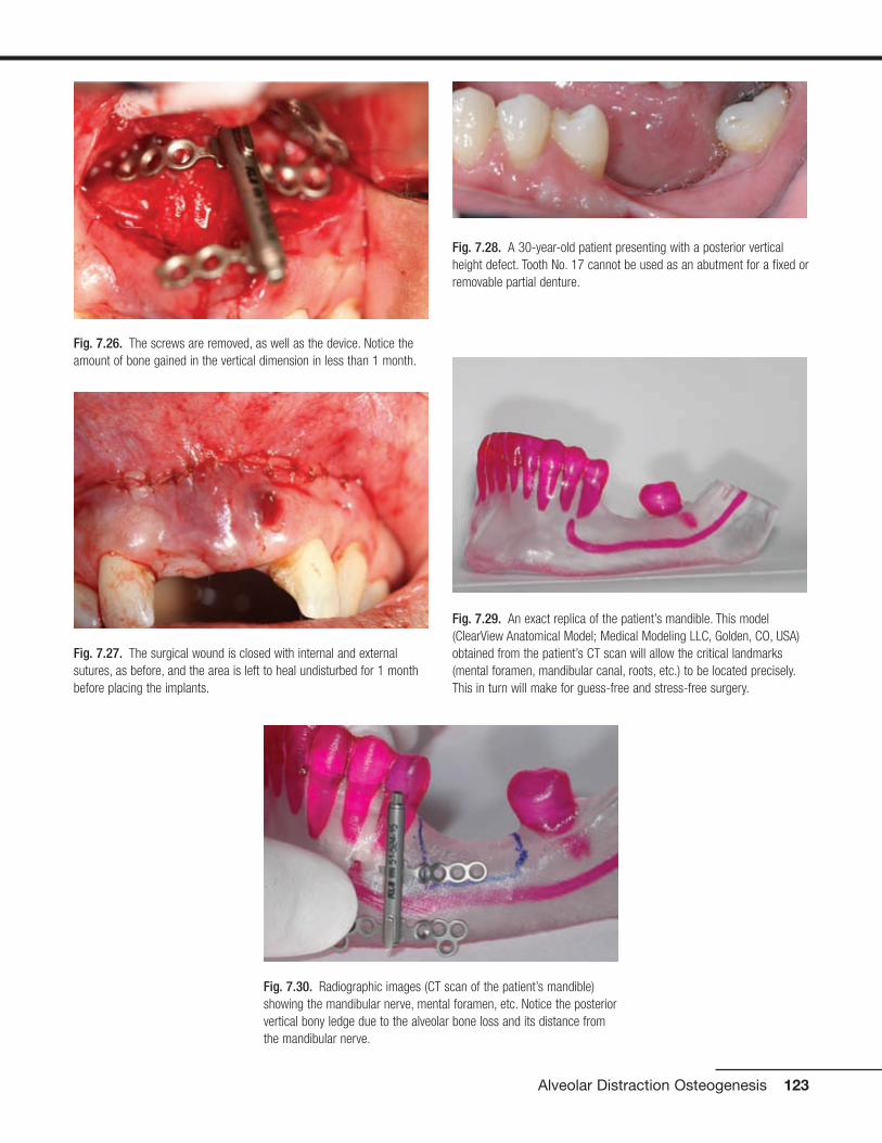
Alveolar Distraction Osteogenesis 123
Fig. 7.26. The screws are removed, as well as the device. Notice theamount of bone gained in the vertical dimension in less than 1 month.
Fig. 7.27. The surgical wound is closed with internal and externalsutures, as before, and the area is left to heal undisturbed for 1 monthbefore placing the implants.
Fig. 7.28. A 30-year-old patient presenting with a posterior verticalheight defect. Tooth No. 17 cannot be used as an abutment for a fixed orremovable partial denture.
Fig. 7.29. An exact replica of the patient’s mandible. This model(ClearView Anatomical Model; Medical Modeling LLC, Golden, CO, USA)obtained from the patient’s CT scan will allow the critical landmarks(mental foramen, mandibular canal, roots, etc.) to be located precisely.This in turn will make for guess-free and stress-free surgery.
Fig. 7.30. Radiographic images (CT scan of the patient’s mandible)showing the mandibular nerve, mental foramen, etc. Notice the posteriorvertical bony ledge due to the alveolar bone loss and its distance fromthe mandibular nerve.

tremely accurate model, and the distractor is bent andadapted beforehand (Fig. 7.31). This will save considerabletime, stress, and aggravation during the surgery.
A Few Words of Caution
• Pay special attention to the direction of the vector in thelower anterior mandibular region (Figs. 7.32 and 7.33).
• Make sure that the distractor does not interfere with theocclusion.
• Select patients who are reliable and compliant.
• Always “overdistract” by a couple of miilimeters to ensureyou will have enough bone.
Preoperative Instructions
• Antibiotherapy (i.e., amoxicillin 500 mg 3 times a day start-ing the day of surgery and for 7 days) is indicated.
• Mild oral sedation could be useful (i.e., diazepam 5 mg thenight before and 5 mg 1 hour before the procedure).
• Analgesics are recommended (i.e., ibuprofen 600 mg 1hour before the surgery).
124 Practical Advanced Periodontal Surgery
Fig. 7.31. The segment to be distracted is drawn on the model and willbe replicated in the mouth precisely during the surgery. The distractorarms are modified and bent prior to the surgery to fit the clinical situa-tion. This will save a lot of time and aggravation during the surgery.
Fig. 7.32. The arrow shows an incorrect vector of distraction. The bonysegment will be too lingual and therefore could not be used for properdental implant placement.
Fig. 7.33. The arrow shows a correct vector of distraction. The bonysegment will be distracted parallel with the long axis of the adjacentteeth. Dental implants can be placed in the proper alignment.

Postoperative Instructions
• Corticosteroids for 5 days: dexamethasone 0.75 mg, 5tablets the day of surgery, then 4 tablets the next day, then3 tablets, and so on, to control the swelling
• Analgesics: acetaminophen with codeine (Tylenol #3) oribuprofen 600 mg (Motrin 600) to control the pain
• Ice pack 20 minutes on/20 minutes off for the first 24 hours
• Chlorhexidine rinses twice a day for 7 days
Possible Complications
• Possible necrosis of the bony segment if it is too small orcompletely detached from the periosteum
• Fibrous tissue formation at the end of the traction period:this is more likely to occur if the traction has been too vig-orous (i.e., 1 mm/day or more)
• Infection
• Fracture of transport segment
• Fracture of anchorage segment
• Premature consolidation
• Undesirable transport vector
• Fracture of the distraction rod or of the transport disc(Mazzonetto and Torrezan, 2003)
REFERENCESBirch, J.G., and M.L. Samchukov. 2004. Use of the Ilizarov method to
correct lower limb deformities in children and adolescents. J. Am.Acad. Orthop. Surg. 12(3):144–154.
Block, M.S., A. Chang, and C. Crawford. 1996. Mandibular alveolarridge augmentation in the dog using distraction osteogenesis. J. OralMaxillofac. Surg. 54(3):309–314.
Chiapasco, M., U. Consolo, A. Bianchi, and P. Ronchi. 2004. Alveolardistraction osteogenesis for the correction of vertically deficient eden-tulous ridges: a multicenter prospective study on humans. Int. J. OralMaxillofac. Implants 19(3):399–407.
Chin, M., and B.A. Toth. 1996. Distraction osteogenesis in maxillofacialsurgery using internal devices: review of five cases. J. Oral Maxillofac.Surg. 54(1):45–53.
Cope, J.B., and M.L. Samchukov. 2001. Mineralization dynamics of re-generate bone during mandibular osteodistraction. Int. J. OralMaxillofac. Surg. 30(3):234–242.
Dibart, S., and M. Karima. 2006. Practical Periodontal Plastic Surgery.Blackwell Publishing, Ames, IA.
Ilizarov, G.A. 1971. Basic principles of transosseous compression anddistraction osteosynthesis. Orthop. Travmatol. Protez. 32(11):7–15.
Mazzonetto, R., M. Allais, P.E. Maurette, and R.W. Moreira. 2007. A ret-rospective study of the potential complications during alveolar distrac-tion osteogenesis in 55 patients. J. Oral Maxillofac. Surg. 36:6–10.
McCarthy, J.G., D.A. Staffenberg, R.J. Wood, C.B. Cutting, B.H. Gray,and T.H. Thorne. 1995. Introduction of an intra-oral bone lengtheningdevice. Plast. Reconstr. Surg. 96(4):978–981.
Ortiz Monasterio, F., F. Molina, L. Andrade, C. Rodrigues, and J. SainzArregui. 1997. Simultaneous mandibular and maxillary distraction inhemifacial microsomia in adults: avoiding occlusal disasters. Plast.Reconstr. Surg. 100(4):852–861.
Samchukov, M.L., J.B. Cope, R.B. Harper, and J.D. Ross. 1998.Biomechanical considerations of mandibular lengthening and widen-ing by gradual distraction using a computer model. J. Oral Maxillofac.Surg. 56(1):51–59.
Alveolar Distraction Osteogenesis 125

HISTORY
The presence of a “black triangle” due to the absence of inter-proximal papilla between two adjacent implants has become asteady concern among implant surgeons and restorative den-tists. Three main surgical methods have been proposed in thepast at second-stage surgery (uncovering) to correct the prob-lem. Palacci in 1995 suggested that a full-thickness flap beraised from the palatal side of the implant and a portion of it berotated 90 degrees to accommodate the interproximal spaceof the implant. Possible compromise of the blood supply of therotated small flap, limited amount of pedunculated soft tissuefor some larger interproximal areas, and lack of keratinized tis-sue in cases with a narrow band of attached gingiva on the fa-cial seem to be some of the limitations of this technique. In1999, Adriaenssens et al. introduced a novel flap design, the“palatal sliding strip flap,” to help form papillae between im-plants and between natural teeth on the anterior area of themaxilla. The flap was designed and managed in a way that al-lowed the palatal mucosa to slide in a labial direction after dis-section of two mesial and distal strips (to create papillae and atthe same time augment the labial ridge).
Nemcovsky et al. in 2000 introduced a U-shaped flap raised to-ward the buccal; the nature of this design was essentially thesame as the one introduced earlier by Adriaenssens, with someminor differences. In 2004, Misch et al. modified Nemcovsky etal.’s technique further by raising the U-shaped flap toward thepalatal rather than the buccal side. In 2004, Shahidi developeda surgical procedure with the goal of guiding the soft tissue thatformerly covered the implant over to the sides of the implant
and to gently squeeze this piece of tissue after insertion of thehealing abutment. This was done to provide enough soft tissuein the interproximal spaces to allow for papilla generation.
In brief, there is not one single technique that is universallyaccepted to be the one that works 100% of the time. Tissueengineering, with the implantation of fibroblasts in the papil-lary area, may, in the future, help solve this problem by pro-viding more predictability.
INDICATIONS
• At second-stage dental implant uncovering, between animplant and a tooth or between two or more implants, tominimize the formation of a “black triangle”
• Thick periodontal biotype
CONTRAINDICATIONS
• Thin periodontal biotype
• Lack of keratinized gingiva around the implant(s)
• Need to correct underlying bone
ARMAMENTARIUM
• A basic surgical set as described in Practical PeriodontalPlastic Surgery
• Implant kit
• Healing abutments
TECHNIQUE
In the single implant model, a small U-shaped flap is created toallow mobilization of the tissue in the mesial direction. AnotherU-shaped flap, mirror image of the first one and sharing thesame buccolingual incision, allows mobilization of the tissuesto the distal direction. Occlusally, these full- or partial-thicknessU-shaped flaps form an H-shape design (Fig. 8.1). The exact
127
Chapter 8 Papillary Construction After Dental Implant Therapy
Peyman Shahidi, DDS, MScD, Serge Dibart, DMD,
and Yun Po Zhang, PhD, DDS(hon)
Fig. 8.1. Diagram showing the uncovering incision and procedures for asingle implant occlusally (a) and buccally (b) and with the healing abut-ment in place (c).

location of the implant is obtained using periapical/bitewing radiographs in combination with alveolar ridge map-ping with an explorer following local anesthesia.
In a multiple implant model (Fig. 8.2), the covering tissue ofthe most mesial implant provides the proximal papilla (i.e.,mesial) of that implant using the U-shape design; the secondimplant provides the contralateral papilla (i.e., distal) of thefirst implant.
After proper local anesthesia (Fig. 8.3), the initial incisions,made using a No. 15 blade, are done as follows:
1. The first incision is done in a buccopalatal–lingual direc-tion. The location ranges from the distal edge of the plat-form of the implant to the middle of the platform, depend-ing upon the amount of tissue needed between implantsor between implant and adjacent tooth.
2. The second step involves the placement of a mesiodistalincision on the buccal side for each implant, perpendicu-lar to the first buccolingual incision. The incision is contin-ued in a slight parabola buccally when there is adequatekeratinized gingiva on the buccal to create a gingival mar-gin around the implant. The incision is continued in a slightparabola palatally if there is insufficient keratinized gingivaon the buccal. Precautions must be taken to preservebuccal keratinized tissue. The incision passes the mesial
or distal platform of the implant and ends halfway betweenthe platform and the adjacent implant or tooth.
3. The third step involves the placement of a mesiodistal inci-sion on the lingual/palatal parallel to the incision on thebuccal. The incision for the anterior implants curves slightlyoff buccally in the middle, as the top of the papilla shouldbe smaller than its base in the buccolingual direction. Inposterior implants, the incision is also placed slightlypalatally because the width of the platform of a posteriorimplant is usually smaller than the width of its crown. Thisis essential in gaining an adequate buccolingual/palatalpapilla or col width to cover the interproximal space.
4. Flaps are elevated by using the tip of the blade and the tipof an Orban knife. First, the soft tissues are reflected fromthe underlying implant; then each mini-flap is underminedby the No. 15 blade and the Orban knife, and the full- orpartial-thickness mini-flap is extended to about 1 mm fromthe adjacent implant or tooth.
Flaps are mobilized and pushed in the mesial and distal di-rections to open a “window” and place the healing abutment.The application of gauze in the area for a few minutes facili-tates the molding of the tissues while pushing the tissues tothe sides. After removing the cover screw, a healing abut-ment with proper height, width, and shape is inserted into theimplant with or without a provisional restoration. This shapesthe future papilla by pushing the tissues to the sides andholding them upright (Figs. 8.4 and 8.5). The same techniqueis repeated for implant(s) distal to the first implant. No suturesare applied, because healing abutments hold the tissues inthe proper position.
The patient then receives postoperative instructions and isscheduled for a follow-up visit within 7 to 10 days.
128 Practical Advanced Periodontal Surgery
Fig. 8.3. Before uncovering of implant Nos. 4 and 5.
Fig. 8.2. Diagram showing the uncovering incision and procedures fortwo implants side by side, occlusally (a) and bucally (b) with the healingabutments in place (c).
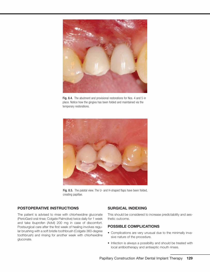
POSTOPERATIVE INSTRUCTIONS
The patient is advised to rinse with chlorhexidine gluconate(PerioGard oral rinse; Colgate Palmolive) twice daily for 1 weekand take ibuprofen (Advil) 200 mg in case of discomfort.Postsurgical care after the first week of healing involves regu-lar brushing with a soft bristle toothbrush (Colgate 360-degreetoothbrush) and rinsing for another week with chlorhexidinegluconate.
SURGICAL INDEXING
This should be considered to increase predictability and aes-thetic outcome.
POSSIBLE COMPLICATIONS
• Complications are very unusual due to the minimally inva-sive nature of the procedure.
• Infection is always a possibility and should be treated withlocal antibiotherapy and antiseptic mouth rinses.
Papillary Construction After Dental Implant Therapy 129
Fig. 8.4. The abutment and provisional restorations for Nos. 4 and 5 inplace. Notice how the gingiva has been folded and maintained via thetemporary restorations.
Fig. 8.5. The palatal view. The U- and H-shaped flaps have been folded,creating papillae.
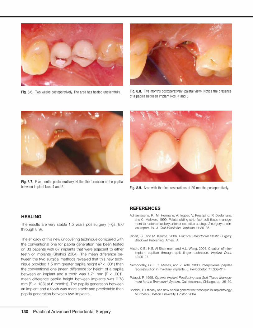
HEALING
The results are very stable 1.5 years postsurgery (Figs. 8.6through 8.9).
The efficacy of this new uncovering technique compared withthe conventional one for papilla generation has been testedon 33 patients with 67 implants that were adjacent to eitherteeth or implants (Shahidi 2004). The mean difference be-tween the two surgical methods revealed that this new tech-nique provided 1.5 mm greater papilla height (P < .001) thanthe conventional one (mean difference for height of a papillabetween an implant and a tooth was 1.71 mm [P < .001],mean difference papilla height between implants was 0.78mm [P < .138] at 6 months). The papilla generation betweenan implant and a tooth was more stable and predictable thanpapilla generation between two implants.
REFERENCESAdriaenssens, P., M. Hermans, A. Ingber, V. Prestipino, P. Daelemans,
and C. Malevez. 1999. Palatal sliding strip flap: soft tissue manage-ment to restore maxillary anterior esthetics at stage 2 surgery: a clin-ical report. Int. J. Oral Maxillofac. Implants 14:30–36.
Dibart, S., and M. Karima. 2006. Practical Periodontal Plastic Surgery.Blackwell Publishing, Ames, IA.
Misch, C.E., K.E. Al Shammori, and H.L. Wang. 2004. Creation of inter-implant papillae through split finger technique. Implant Dent.13:20–27.
Nemcovsky, C.E., O. Moses, and Z. Artzi. 2000. Interproximal papillaereconstruction in maxillary implants. J. Periodontol. 71:308–314.
Palacci, P. 1995. Optimal Implant Positioning and Soft Tissue Manage-ment for the Branemark System. Quintessence, Chicago, pp. 35–39.
Shahidi, P. Efficacy of a new papilla generation technique in implantology.MS thesis. Boston University. Boston 2004.
130 Practical Advanced Periodontal Surgery
Fig. 8.8. Five months postoperatively (palatal view). Notice the presenceof a papilla between implant Nos. 4 and 5.
Fig. 8.9. Area with the final restorations at 20 months postoperatively.
Fig. 8.6. Two weeks postoperatively. The area has healed uneventfully.
Fig. 8.7. Five months postoperatively. Notice the formation of the papillabetween implant Nos. 4 and 5.
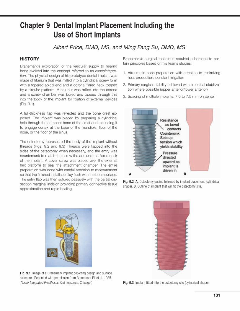
HISTORY
Branemark’s exploration of the vascular supply to healingbone evolved into the concept referred to as osseointegra-tion. The physical design of his prototype dental implant wasmade of titanium that was milled into a cylindrical screw formwith a tapered apical end and a coronal flared neck toppedby a circular platform. A hex nut was milled into the coronaand a screw chamber was bored and tapped through thisinto the body of the implant for fixation of external devices(Fig. 9.1).
A full-thickness flap was reflected and the bone crest ex-posed. The implant was placed by preparing a cylindricalhole through the compact bone of the crest and extending itto engage cortex at the base of the mandible, floor of thenose, or the floor of the sinus.
The osteotomy represented the body of the implant withoutthreads (Figs. 9.2 and 9.3) Threads were tapped into thesides of the osteotomy when necessary, and the entry wascountersunk to match the screw threads and the flared neckof the implant. A cover screw was placed over the externalhex platform to seal the attachment chamber. The entirepreparation was done with careful attention to measurementso that the finished installation lay flush with the bone surface.The entry flap was then sutured passively with the partial dis-section marginal incision providing primary connective tissueapproximation and rapid healing.
Branemark’s surgical technique required adherence to cer-tain principles based on his teams studies:
1. Atraumatic bone preparation with attention to minimizingheat production: constant irrigation
2. Primary surgical stability achieved with bicortical stabiliza-tion where possible (upper anterior/lower anterior)
3. Spacing of multiple implants: 7.0 to 7.5 mm on center
131
Chapter 9 Dental Implant Placement Including the Use of Short Implants
Albert Price, DMD, MS, and Ming Fang Su, DMD, MS
Fig. 9.1 Image of a Branemark implant depicting design and surfacestructure. (Reprinted with permission from Branemark PI, et al. 1985.Tissue-Integrated Prostheses. Quintessence, Chicago.)
Fig. 9.2 A, Osteotomy outline followed by implant placement (cylindricalshape). B, Outline of implant that will fit the osteotomy site.
Fig. 9.3 Implant fitted into the osteotomy site (cylindrical shape).

4. Provide healing interval with no direct load to allow undis-turbed osseointegration
Most of these early implants were placed in the mandibulebetween the mental foramina and maxillary anterior/bicuspidregions. The objective was to offer an alternative to an inad-equate removable prosthesis.
Implants have become a standard of care and the treatmentof choice for replacement of missing teeth. All areas of themouth have been restored, and while the threaded implant isstill the dominant form, the cylindrical shape and the attach-ment platform have evolved.
Three basic forms that are available are the cylinder withscrew threads (Branemark’s design), the tapered cylinderwith threads (e.g., Zimmer [Figs. 9.4 and 9.5]), and the ta-pered form without threads, which is press fit (Bicon [Fig. 9.6]and Endopore). The internal architecture of the bone influ-ences the effectiveness of these forms to gain the necessarystability at time of placement.
Branemark stressed bicortical stabilization as a method tosecure his implant system. His mechanical shape createsstability by the resistance of the countersink to the draw orpull of the threads into the bony preparation (Fig. 9.2A); thisrequires heavy compact bone at each end of the osteotomy.To ensure maximum use of bone and bicortical engagement(CT was not available then), the suggestion was made toplace the finger firmly against the base of the mandible andto feel that the bur had penetrated the cortex. In the maxillaryanterior, one was to place the finger in the nasal areas to feelthe penetration of the floor of the nose (cortex). If the internal
architecture had trabeculae of sufficient bulk, then the en-gagement of the more compact border areas was notneeded. However, if the trabeculae were thin and widelyspaced, such as in the upper and lower posterior, then thescrew pressures could break or strip the bone threads in thebody and apex area of the implant or collapse the coronalbevel and result in a “spinner.” It is possible to engage thecortex at the floor of the sinus and the top of the mandibularcanal, but this is often not desirable.
As the scope of placement widened to include the posteriorareas and single tooth sites, the need for alternate mechan-ics of surgical stability evolved.
132 Practical Advanced Periodontal Surgery
Fig. 9.6 Bicon short implant (5.7 � 6 mm) placed in the mandible(especially useful in cases with insufficient bony height).
Fig. 9.4 Tapered implant and outline of osteotomy site.Fig. 9.5 Tapered implant within the osteotomy site.

Originally designed to fit tapered cross sectional sites (areaswith depressions like the incisal fossa and the depressionover the upper first bicuspid) the tapered form is especiallyuseful in areas of light, thin trabeculation (Fig. 9.7)
The tapered screw form provides an alternative method ofachieving surgical stability. Its wedge-shaped screw formachieves compression of the tapered osteotomy along its en-tire surface (see Figs. 9.4 and 9.5).
INDICATIONS
Dental implants are used to:
1. Replace individual teeth
2. Support fixed and removable prostheses
3. Anchor maxillofacial prosthesis
4. Act as anchorage for orthodontic movement
Dental Implant Placement 133
Fig. 9.7 Dry scull and CT scan showing specific anatomic features and trabeculation of the maxillary bone.

TECHNIQUE
Anesthesia
Block anesthesia is the most efficient. Marcaine supple-mented with lidocaine provides 3 to 4 hours of good workinganesthesia with minimal local reinforcement. Some practition-ers prefer only infiltration so that the patient “feels” the prox-imity to vital structures and thus avoid potential damage tonerves. With a distortion level of 1% or less, the reformattedCT images, coupled with a surgeon’s “feel” for anatomy, canbe used with confidence (Figs. 9.8 and 9.9).
IMPLANT PLACEMENT
Entry Incision
The objective is to expose the bone where the osteotomy isto be placed and to minimize vascular disruption to sensitivebone areas (Fig. 9.10).
134 Practical Advanced Periodontal Surgery
Fig. 9.8 A, Panoramic radiograph (distortion ±25%). B, Periapical radiograph (distortion ±15%).
Fig. 9.9 A, Tomograph: “foggy” quality and slice thickness distortimage. B, CT scan: distortion ±1%.

Incisions vary with site objective and history of local trauma.
1. If one-stage implant or immediate load, a mid crestal inci-sion with intrasulcular extensions buccally and lingually isused.
2. If classic delayed, two-stage implant, then
• In the maxillary arch, a horizontal incision is usuallymade just to the palatal of line angles and two verticalincisions sparing the proximal papillae are extendedthrough the mucogingival junction (MGJ) on the buccal.The flap is reflected into the vestibule and no retractionis needed (Fig. 9.11).
• In the mandibular arch, an incision is made just to thebuccal of line angles, or if the MGJ is close to this area,the incision is made below the MGJ and reverse split forabout 2 mm to leave a small bed of periosteum behind.Vertical incisions sparing the papillae are extended overthe crest and through the lingual MGJ. The flap is re-
flected to the lingual and usually buckles over onto itself,avoiding need for retraction.
3. If dealing with multiple implants in a severely resorbedlower arch with no vestibular depth, then an incision ismade in middle of available keratinized tissue, reflectingenough to expose the crest.
SITE PREPARATION
The only time one needs to reduce bone at the site is a re-quirement for increased interocclusal space. It should bekept in mind that reducing the bone increases the crown-rootratio of the prosthesis, which increases stress-strain relation-ships at the abutment–implant interface.
The Osteotomy: Single Implant
The central goal is to have the implant perpendicular to theplane of occlusion, in the center of the occlusal table of therespective tooth form, and to have at least 1 mm of bone on
Dental Implant Placement 135
Fig. 9.10 Incision design buccally (A) and palatally (B) before the place-ment of implant No. 4.
A
B
Fig. 9.11 Full-thickness flap is reflected, exposing the alveolar crest,(A), buccally and (B), palatally.
A
B

all sides of implant. It is estimated that at least 0.5 mm ofbone is necrosed in the most careful surgery (Rhinelander1974a, 1974b).
Preparation
1. Using a small round bur (Fig. 9.12), the mesial–distal, buc-cal–lingual location is marked with a small depression.This is remeasured and accepted or changed, and thenthe crest is deepened for 2 to 3 mm with copious irriga-tion to penetrate the crestal cortex. In some sites, afterpenetrating 1 to 2 mm, the bur may suddenly drop (upperand lower posterior). If this happens, a perioprobe shouldbe inserted and pushed until resistance is detected. Theprobe may drop 10 mm in areas of very little trabecularcontent. Caution during preparation should be used toachieve surgical stability.
2. The starting cylinder bur is usually 2.0 to 2.5 mm in diam-eter (Fig. 9.13), but in very dense bone, the addition of a1.5-mm bur is useful. The burs should have guide marksto mark vertical depth, and these should be checkedagainst a common rule (periodontal probe) for actualdepth and reference to CT scan measurements. Many drillsystems do not count the bevel at tip of bur, and the mark-ings may not represent millimeters but instead a preferreddepth for ideal placement of the implant. (It is assumedthat a CT scan or some method of judging distance to vitalstructure has been used in treatment planning.)
At this stage, it is prudent to drill only as deep as needed tocheck vertical angulation (7 to 8 mm) with a direction guide.If a change is to be made, then it should be done before pro-ceeding to larger drills. Sometimes it is necessary to use theround bur again to force this change. The direction guide withstring attached is then placed (Figs. 9.14 and 9.15). Thecylinder bur is aligned with this guide and then changed to
the new direction. The guide is pulled and the correction ismade. Once the new direction is acceptable, the site is drilledto final depth. If vertical bone allows, overdrill the depth of thesite by about 1.0 mm in the initial drill steps. This allows moreflexibility as larger burs are used because they are not effi-cient end-cutters and can generate heat if pushed too hardtrying to achieve increased depth at later stages. (Internally ir-rigated burs have not been found practical because theyconstantly clog and irrigation fails.)
Once the initial burs have created place and angulation, thesite is gradually enlarged to the final size according to thesteps recommended by the implant system guide.
WARNING: DRILL SPEED: Each drill system has beenengineered to be run at certain speeds; failure to followrecommendations may overheat bone. Irrigation shouldbe constant and drilling is done in a pumping action toremove bone filings, especially in very compact bone.(In the lower anterior, it is sometimes necessary tochange to a new bur after one osteotomy; rememberthat the smaller burs are being used in every case.)
136 Practical Advanced Periodontal Surgery
Fig. 9.12 Using a round bur, future site of implant osteotomy is marked.
Fig. 9.13 Pilot drill is used to initiate the osteotomy.
Fig. 9.14 Directional guide shows the proper alignment of the implantbuccally.
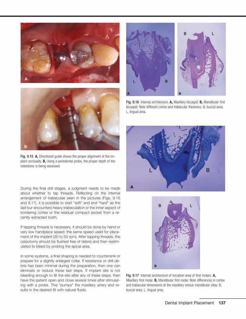
During the final drill stages, a judgment needs to be madeabout whether to tap threads. Reflecting on the internalarrangement of trabeculae seen in the pictures (Figs. 9.16and 9.17), it is possible to start “soft” and end “hard” as thelast bur encounters heavy trabeculation or the inner aspect ofbordering cortex or the residual compact socket from a re-cently extracted tooth.
If tapping threads is necessary, it should be done by hand orvery low handpiece speed; the same speed used for place-ment of the implant (30 to 50 rpm). After tapping threads, theosteotomy should be flushed free of debris and then restim-ulated to bleed by probing the apical area.
In some systems, a final shaping is needed to countersink orprepare for a slightly enlarged collar. If resistance or drill de-bris has been minimal during the preparation, then one caneliminate or reduce these last steps. If implant site is notbleeding enough to fill the site after any of these steps, thenhave the patient open and close several times after stimulat-ing with a probe. This “pumps” the maxillary artery and re-sults in the desired fill with natural fluids.
Dental Implant Placement 137
Fig. 9.15 A, Directional guide shows the proper alignment of the im-plant occlusally. B, Using a periodontal probe, the proper depth of theosteotomy is being assessed.
Fig. 9.17 Internal architecture of furcation area of first molars. A,Maxillary first molar. B, Mandibular first molar. Note differences in cortexand trabecular dimensions at the maxillary versus mandibular sites. B,buccal area; L, lingual area.
Fig. 9.16 Internal architecture. A, Maxillary bicuspid. B, Mandibular firstbicuspid. Note different cortex and trabecular thickness. B, buccal area;L, lingual area.
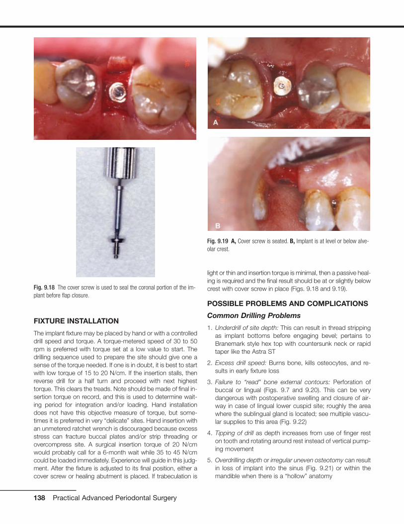
FIXTURE INSTALLATION
The implant fixture may be placed by hand or with a controlleddrill speed and torque. A torque-metered speed of 30 to 50rpm is preferred with torque set at a low value to start. Thedrilling sequence used to prepare the site should give one asense of the torque needed. If one is in doubt, it is best to startwith low torque of 15 to 20 N/cm. If the insertion stalls, thenreverse drill for a half turn and proceed with next highesttorque. This clears the treads. Note should be made of final in-sertion torque on record, and this is used to determine wait-ing period for integration and/or loading. Hand installationdoes not have this objective measure of torque, but some-times it is preferred in very “delicate” sites. Hand insertion withan unmetered ratchet wrench is discouraged because excessstress can fracture buccal plates and/or strip threading orovercompress site. A surgical insertion torque of 20 N/cmwould probably call for a 6-month wait while 35 to 45 N/cmcould be loaded immediately. Experience will guide in this judg-ment. After the fixture is adjusted to its final position, either acover screw or healing abutment is placed. If trabeculation is
light or thin and insertion torque is minimal, then a passive heal-ing is required and the final result should be at or slightly belowcrest with cover screw in place (Figs. 9.18 and 9.19).
POSSIBLE PROBLEMS AND COMPLICATIONS
Common Drilling Problems
1. Underdrill of site depth: This can result in thread strippingas implant bottoms before engaging bevel; pertains toBranemark style hex top with countersunk neck or rapidtaper like the Astra ST
2. Excess drill speed: Burns bone, kills osteocytes, and re-sults in early fixture loss
3. Failure to “read” bone external contours: Perforation ofbuccal or lingual (Figs. 9.7 and 9.20). This can be verydangerous with postoperative swelling and closure of air-way in case of lingual lower cuspid site; roughly the areawhere the sublingual gland is located; see multiple vascu-lar supplies to this area (Fig. 9.22)
4. Tipping of drill as depth increases from use of finger reston tooth and rotating around rest instead of vertical pump-ing movement
5. Overdrilling depth or irregular uneven osteotomy can resultin loss of implant into the sinus (Fig. 9.21) or within themandible when there is a “hollow” anatomy
138 Practical Advanced Periodontal Surgery
Fig. 9.18 The cover screw is used to seal the coronal portion of the im-plant before flap closure.
Fig. 9.19 A, Cover screw is seated. B, Implant is at level or below alve-olar crest.
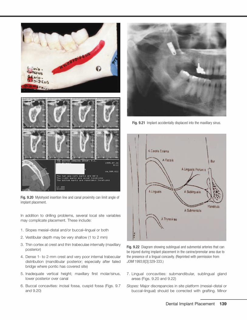
In addition to drilling problems, several local site variablesmay complicate placement. These include:
1. Slopes mesial–distal and/or buccal–lingual or both
2. Vestibular depth may be very shallow (1 to 2 mm)
3. Thin cortex at crest and thin trabeculae internally (maxillaryposterior)
4. Dense 1- to 2-mm crest and very poor internal trabeculardistribution (mandibular posterior; especially after failedbridge where pontic has covered site)
5. Inadequate vertical height; maxillary first molar/sinus,lower posterior over canal
6. Buccal concavities: incisal fossa, cuspid fossa (Figs. 9.7and 9.20)
7. Lingual concavities: submandibular, sublingual glandareas (Figs. 9.20 and 9.22)
Slopes: Major discrepancies in site platform (mesial–distal orbuccal–lingual) should be corrected with grafting. Minor
Dental Implant Placement 139
Fig. 9.20 Mylohyoid insertion line and canal proximity can limit angle ofimplant placement.
Fig. 9.21 Implant accidentally displaced into the maxillary sinus.
Fig. 9.22 Diagram showing sublingual and submental arteries that canbe injured during implant placement in the canine/premolar area due tothe presence of a lingual concavity. (Reprinted with permission fromJOMI 1993;8[3]:329-333.)

contour differences can be adjusted for by interplay be-tween implant anatomy and site anatomy. For example, ifa site has a 2-mm deficiency from mid crest to buccal lineangles, then a Branemark style implant can be used byplacing the implant at the level of the lingual crest. This in-tentionally leaves the buccal bevel exposed, but at 1 year,this bone would have been lost in the cupping resorptionusually seen with this style implant. As long as the palatalbone and half the mesial and distal bone serve the pur-pose of creating surgical stability, the implant placementcan be left at a reasonable height and the C/R ratio is notaffected.
Minimal vestibular depth: This often happens in the lower an-terior with severe resorption, classic Branemark case. Ifthe crest was leveled and the implants are placed by thestandard protocol, then the connections could fall belowthe floor and vestibular depth. By ignoring the buccal andlingual slopes and seating implants at mesial and distal
bone level, the implants can be left above the floor and stillretain maximum bone integration. It is even possible toleave the majority of the bevel above the crest, but thismust be planned ahead and use of mid crestal incision isnecessary.
Thin bone and minimal internal support: The site can be un-derdrilled (stop one drill short of final), laterally compressedwith osteotomes, or site abandoned and allowed to rehealor even grafted internally and revisited at 3 to 4 months.
Inadequate vertical height: Site can be grafted with a blockgraft, or short implants with increased surface area can beused (Fig. 9.23).
Buccal concavities: This can present the most difficulty.Sometimes threaded implants are placed and thengrafted. The implant may be placed at an acute angle andrestored with an angled abutment. This often results in a“knee” at gingival margin, which then recedes and can ex-pose the restorative margin. Another alternative in multiplesite cases is to skip this site and bridge it with a pontic.
Lingual concavities: In the mandibular second molar, one canchange the angle with the direction following the buccalplate. It is necessary to avoid encroachment on tonguespace. Lower cuspid lingual concavity has multiple vascu-lar supply, so it is very dangerous to perforate this area,with the potential for submylohyoid swelling and closure ofairspace (see Fig. 9.22).
Multiple sites: Most of the issues with multiple sites aresolved by good prosthetic guidance. In general, the im-plants need to be placed in the center of the crown shapeto be supported in a buccal–lingual and mesial–distalmanner.
The limits of placement proximity are different for implant-to-implant versus implant-to-tooth.
The general rule is to have at least 2 mm of bone between.This is problematic for two reasons: Tarnow et al. (2003)published data supporting the need for at least 3 mm tosupport interdental papillae. This would apply toBranemark-style implants where the cupping of adjacentimplants would overlap and drop interproximal bone andthe soft tissue above—the interproximal papillae. Otherstyle implants may not present this problem. If one is deal-ing with heavy compact bone such as in the lower ante-rior, then placing implants too close endangers the en-dosseous vascular supply between them and there is therisk of bone necrosis between and loss of both implantsand bone.
Implants can be placed closer to teeth because they havea greater vascular net in their PDL, which is connectedthrough numerous holes to the adjacent marrow.
It may be more prudent to skip an implant and bridge asite if mesial–distal proximity becomes a problem. For ex-
140 Practical Advanced Periodontal Surgery
Fig. 9.23 Anatomic limits. Sinus extension, resulting in less than 1 mmbone at the alveolar crest (top). Crestal resorption: there is less than 7 mm bone above the mandibular canal, impairing standard implantplacement (bottom).

ample, in the upper anterior, it might be better to skip thelateral site if inadequate spacing exists and/or to use thelateral and skip the central position if an overly large incisalforamen is present.
Short implants: In the past several years, the statistical analy-sis has shown decreased success rates with implants lessthan 10 mm. This is being challenged by newer forms and
changed surface textures and treatments. Roughenedsurfaces, square threads, and plate form implants withgreater surface area have been used successfully (Gentile2005). While success rates may not be 100%, it is stillpossible and judicious to use short implants in selectcases, especially when patients refuse extensive graftplacement (Figs. 9.24 through 9.29).
Dental Implant Placement 141
Fig. 9.24 Periapical radiograph showing mandibular molar necessitatingextraction and replacement with implants. Due to insufficient verticalbony height above the mandibular canal, short implants were selected torestore missing dentition.
Fig. 9.25 Short implants (Bicon, Boston, MA, USA) were placed to over-come vertical limitation.
Fig. 9.26 Periapical radiograph showing implants restored.
Fig. 9.27 Clinical picture of restored short implants.
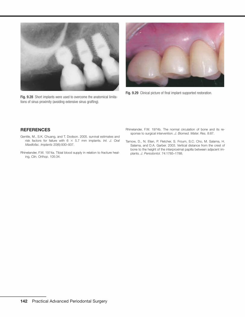
REFERENCES Gentile, M., S.K. Chuang, and T. Dodson. 2005. survival estimates and
risk factors for failure with 6 � 5.7 mm implants. Int. J. OralMaxillofac. Implants 20(6):930–937.
Rhinelander, F.W. 1974a. Tibial blood supply in relation to fracture heal-ing, Clin. Orthop. 105:34.
Rhinelander, F.W. 1974b. The normal circulation of bone and its re-sponse to surgical intervention. J. Biomed. Mater. Res. 8:87.
Tarnow, D., N. Elian, P. Fletcher, S. Froum, S.C. Cho, M. Salama, H.Salama, and D.A. Garber. 2003. Vertical distance from the crest ofbone to the height of the interproximal papilla between adjacent im-plants. J. Periodontol. 74:1785–1788.
142 Practical Advanced Periodontal Surgery
Fig. 9.28 Short implants were used to overcome the anatomical limita-tions of sinus proximity (avoiding extensive sinus grafting).
Fig. 9.29 Clinical picture of final implant-supported restoration.

GINGIVAL NODULES
Nodular proliferations on the gingiva are frequently encoun-tered and represent a number of distinct entities with differ-ent etiologies and treatment strategies. While most representreactive or inflammatory processes, occasionally lesions arisethat are developmental in nature, perhaps resulting fromstimulation of residua of odonotogenesis that persist in theoral mucosa following tooth development.
PARULIS
Inflammatory infiltrates at the apices of nonvital teeth occa-sionally channelize through medullary alveolar bone, pene-trate the cortical bone and soft tissue, and drain into the oralcavity. These inflammatory infiltrates typically follow a path ofleast resistance. Given this trend, in most regions inflamma-tory apical lesions will drain into the oral cavity through asinus tract on the buccal aspect of the alveolar bone due todecreased thickness of the buccal cortical plate comparedwith the lingual cortex. Exceptions to this rule are the man-dibular second and third molars, the palatal roots of maxillarymolars and the maxillary lateral incisors, which typically per-forate lingually. At the orifice of the sinus tract, a focal nodu-lar proliferation of inflamed granulation tissue may arise,termed a “parulis” or “gum boil” (Fig. 10.1).
The parulis represents a focus of communication between apathologic cavity associated with an odontogenic infectionand the oral cavity. Therefore, it is frequently possible to insert
a gutta-percha point into the sinus tract and trace its path tothe tooth that represents the source of the infection. If thesinus tract remains patent, chronic drainage will allow the of-fending tooth to be asymptomatic. If the sinus tract becomesobstructed, symptoms of odontogenic infection will typicallyarise. A parulis typically resolves following endodontic ther-apy or extraction of the offending tooth; however, residual mi-croorganisms and inflammation that persist along a sinustract following treatment may cause the parulis to persist. Insuch instances, excision may be required.
FIBROMA
A fibroma represents a nodular proliferation of dense fibrousconnective tissue that arises secondary to trauma or focal ir-ritation. Representing the most common reactive proliferationof the oral cavity, fibromas typically present as smooth-surfaced firm nodular lesions that are similar in color to thesurrounding mucosa (Fig. 10.2). If the lesion is frequentlytraumatized or subjected to constant irritation, surface ulcer-ation or hyperkeratosis may result. One form of fibroma withdistinctive clinicopathologic characteristics termed the giantcell fibroma appears to have no association with trauma andis often described clinically as having a papillary surface ar-chitecture. With a predilection for occurring on the gingiva(Magnusson and Rasmusson 1995), the giant cell fibroma istypically diagnosed in patients under age 30. The histopatho-logic appearance is distinctive due to the presence of multi-nucleated and stellate cells throughout the densely collage-nized connective tissue stroma thought to be derived from
143
Chapter 10 Periodontal Medicine Including Biopsy Techniques
Vikki Noonan, DMD, DMSc, and Sadru Kabani, DMD, MS
Fig. 10.1 Nodular erythematous mass of granulation tissue near themucobuccal fold and associated with an asymptomatic nonvital premolar.(Image courtesy of Dr. Helen Santis.)
Fig. 10.2 Pink, smooth-surfaced nodular mass of the mandibularattached gingiva. (Image courtesy of Dr. Helen Santis.)
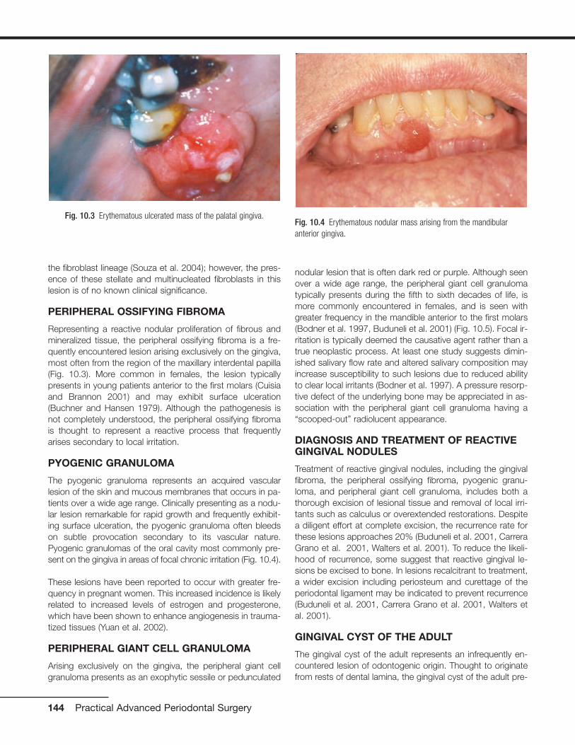
the fibroblast lineage (Souza et al. 2004); however, the pres-ence of these stellate and multinucleated fibroblasts in thislesion is of no known clinical significance.
PERIPHERAL OSSIFYING FIBROMA
Representing a reactive nodular proliferation of fibrous andmineralized tissue, the peripheral ossifying fibroma is a fre-quently encountered lesion arising exclusively on the gingiva,most often from the region of the maxillary interdental papilla(Fig. 10.3). More common in females, the lesion typicallypresents in young patients anterior to the first molars (Cuisiaand Brannon 2001) and may exhibit surface ulceration(Buchner and Hansen 1979). Although the pathogenesis isnot completely understood, the peripheral ossifying fibromais thought to represent a reactive process that frequentlyarises secondary to local irritation.
PYOGENIC GRANULOMA
The pyogenic granuloma represents an acquired vascularlesion of the skin and mucous membranes that occurs in pa-tients over a wide age range. Clinically presenting as a nodu-lar lesion remarkable for rapid growth and frequently exhibit-ing surface ulceration, the pyogenic granuloma often bleedson subtle provocation secondary to its vascular nature.Pyogenic granulomas of the oral cavity most commonly pre-sent on the gingiva in areas of focal chronic irritation (Fig. 10.4).
These lesions have been reported to occur with greater fre-quency in pregnant women. This increased incidence is likelyrelated to increased levels of estrogen and progesterone,which have been shown to enhance angiogenesis in trauma-tized tissues (Yuan et al. 2002).
PERIPHERAL GIANT CELL GRANULOMA
Arising exclusively on the gingiva, the peripheral giant cellgranuloma presents as an exophytic sessile or pedunculated
nodular lesion that is often dark red or purple. Although seenover a wide age range, the peripheral giant cell granulomatypically presents during the fifth to sixth decades of life, ismore commonly encountered in females, and is seen withgreater frequency in the mandible anterior to the first molars(Bodner et al. 1997, Buduneli et al. 2001) (Fig. 10.5). Focal ir-ritation is typically deemed the causative agent rather than atrue neoplastic process. At least one study suggests dimin-ished salivary flow rate and altered salivary composition mayincrease susceptibility to such lesions due to reduced abilityto clear local irritants (Bodner et al. 1997). A pressure resorp-tive defect of the underlying bone may be appreciated in as-sociation with the peripheral giant cell granuloma having a“scooped-out” radiolucent appearance.
DIAGNOSIS AND TREATMENT OF REACTIVEGINGIVAL NODULES
Treatment of reactive gingival nodules, including the gingivalfibroma, the peripheral ossifying fibroma, pyogenic granu-loma, and peripheral giant cell granuloma, includes both athorough excision of lesional tissue and removal of local irri-tants such as calculus or overextended restorations. Despitea diligent effort at complete excision, the recurrence rate forthese lesions approaches 20% (Buduneli et al. 2001, CarreraGrano et al. 2001, Walters et al. 2001). To reduce the likeli-hood of recurrence, some suggest that reactive gingival le-sions be excised to bone. In lesions recalcitrant to treatment,a wider excision including periosteum and curettage of theperiodontal ligament may be indicated to prevent recurrence(Buduneli et al. 2001, Carrera Grano et al. 2001, Walters etal. 2001).
GINGIVAL CYST OF THE ADULT
The gingival cyst of the adult represents an infrequently en-countered lesion of odontogenic origin. Thought to originatefrom rests of dental lamina, the gingival cyst of the adult pre-
144 Practical Advanced Periodontal Surgery
Fig. 10.4 Erythematous nodular mass arising from the mandibularanterior gingiva.
Fig. 10.3 Erythematous ulcerated mass of the palatal gingiva.

sents as a fluid-filled swelling typically arising on the labial at-tached gingiva of the premolar-canine region of the mandible(Buchner and Hansen 1979, Nxumalo and Shear 1992) (Fig.10.6). Reported to primarily present during the fifth and sixthdecades of life (Giunta 2002, Nxumalo and Shear 1992), thegingival cyst of the adult may occasionally cause a pressureresorptive defect of the subjacent alveolar bone that maycause the entity to be mistaken for a lateral periodontal cyst(Giunta 2002). Rare examples of multiple lesions have beendescribed (Giunta 2002, Shade et al. 1987). Treatment con-sists of simple surgical excision with submission of lesionaltissue for histopathologic examination.
MUCOCELE
The mucocele is a frequently encountered lesion of the oralmucosa characterized by extravasated mucoid material that
leads to a fluctuant nodular swelling of the mucosa, often re-markable for a bluish hue. Typically found on the lower labialmucosa lateral to the midline (Fig. 10.7) but noted in the buc-cal mucosa, floor of the mouth (ranula), and the anterior ven-tral tongue, mucoceles frequently arise secondary to a focaltraumatic injury that causes rupture of an excretory duct withsubsequent spillage of mucin into the surrounding connectivetissue. The feeder salivary gland typically retains its capacityto produce secretion; however, the damaged duct preventspassage of saliva into the oral cavity. Patients typically com-plain of the lesion waxing and waning as the gland producessaliva and then empties. Occasionally, mucoceles are foundon the posterior palate, posterior buccal mucosa, and retro-molar trigone; most frequently, these lesions represent super-ficial mucoceles. These lesions typically present as smallfluid-filled vesicles that rupture, leaving ulcerative lesions thatoccasionally recur. Tarter control toothpaste (Navazesh 1995)has been linked to the formation of these lesions, and theyhave also been described to occur more frequently at meal-time.
Additionally, superficial mucoceles have been reported inearly stages of graft-versus-host disease (Garcia et al. 2002).A mucous cyst represents a true cystic lesion; the lining is de-rived from salivary ductal epithelium. These lesions are fre-quently located in the lips and buccal mucosa and are seenin association with ductal obstruction such as sialolithiasisthat may increase intraluminal pressure; however, true devel-opmental cystic lesions are seen.
Periodontal Medicine and Biopsy Techniques 145
Fig. 10.7 Bluish fluctuant swelling of the lower labial mucosa. (Imagecourtesy of Dr. Helen Santis.)
Fig. 10.5 Ulcerated reddish-purple mass of the mandibular anteriorgingiva.
Fig. 10.6 Fluid-filled lesion in the mandibular premolar region of theattached gingiva.

DESQUAMATIVE GINGIVITIS
Desquamative gingivitis is a clinically descriptive term that ischaracterized by sloughing, erythematous areas of the at-tached gingiva. These desquamative gingival changes maybe appreciated in the context of vesiculoerosive conditions,including pemphigus vulgaris, mucous membrane (cicatricial)pemphigoid, erosive lichen planus, linear IgA disease, graft-versus-host disease, paraneoplastic pemphigus, epidermoly-sis bullosa acquisita, systemic lupus erythematosus, chroniculcerative stomatitis, contact hypersensitivity reactions, andforeign-body gingivitis (2003) (Portions reprinted with permis-sion from the Journal of the Massachusetts Dental Society2005 Fall;54(3):38).
LICHEN PLANUS
Lichen planus represents an immunologically mediated mu-cocutaneous disease that affects the oral cavity in as muchas 2% of the population. Typically presenting in the fourth tofifth decades of life, lichen planus is characterized by a vari-ety of clinical manifestations including the reticular, erosive,and atrophic forms of the disease. The most commonly af-fected site is the buccal mucosa, followed by the tongue, gin-giva, labial mucosa and lower labial vermilion (Eisen 2002). Injust under 10% of patients lichen planus presents exclusivelyon the gingiva (Eisen 2002, Mignogna et al. 2005) (Fig. 10.8).These cases typically present as the reticular or erosive formsof the disease involving wide areas of marginal and attachedgingiva and most commonly affect women (Mignogna et al.2005). A number of medications (especially antihypertensiveagents), flavoring agents, oral hygiene products, and candiesand chewing gum can elicit a mucosal reaction clinically in-distinguishable from lichen planus. Termed lichenoid mucosi-tis, clinical features, when correlated with histopathologicfindings, help to distinguish the entity from bona fide lichenplanus (Thornhill et al. 2006). Diagnosis is based on aprocess of elimination of suspected stimuli. This is frequentlybased on trial and error and is time consuming. If there is areason to suspect medication-induced mucositis, consulta-tion with the patient’s physician may be helpful to explore thepossibility of substituting the medication. It is reasonable totreat this affliction with topical corticosteroids to controlsymptoms. Chronic ulcerative stomatitis represents an infre-quently encountered condition that shares clinical features oferosive lichen planus superficially and may present asdesquamative gingivitis. While the tongue and buccal mu-cosa are more commonly affected, gingival involvement isclinically indistinguishable from the erosive form of lichenplanus (Solomon et al. 2003). This condition typically pre-sents in women and is characterized by episodes of waxingand waning. Differences in the immunofluorescence profileaid in distinguishing chronic ulcerative stomatitis from lichenplanus. The immunopathologic pattern for lichen planus isnonspecific but frequently consists of shaggy deposition offibrinogen along the epithelial–connective tissue interface,whereas that of chronic ulcerative stomatitis consists of IgG
autoantibodies directed against parabasal and basal strati-fied squamous epithelial cell nuclei. In some instances, alichenoid appearance of the gingiva is seen secondary to theimpregnation of dental materials into the gingiva during den-tal treatment. The term foreign body gingivitis is used todescribe this entity. More common in females, foreign bodygingivitis typically presents as an erythroplakic or erythroleu-koplakic lesion of the gingiva (Fig. 10.9) that does not re-spond to improved oral hygiene measures or minimal im-provement with topical steroid therapy as a result of itsanti-inflammatory effect (Gordon 2000).
PEMPHIGUS VULGARIS
Pemphigus vulgaris represents an autoimmune-mediatedmucocutaneous disease characterized by autoantibody at-tack against components of desmosomes. Frequently repre-senting the initial manifestation of the disease, oral lesions are
146 Practical Advanced Periodontal Surgery
Fig. 10.8 Erosive lichen planus presenting as desquamative gingivitiswith erythema and discomfort. (Image courtesy of Dr. Helen Santis.)
Fig. 10.9 Focal areas of painful erythematous marginal gingiva.

found in most instances and typically present as blisters orerosive lesions of the oral and pharyngeal mucosa. Often theonset is insidious with lesions getting progressively worseover time. Desquamative gingivitis in absence of other clinicalfeatures is a frequently encountered clinical presentation.Here, blisters and/or erosive lesions are seen often extendingto the free gingival tissues (Mignogna et al. 2001) (Fig.10.10). Direct immunofluorescence findings from tissue sub-mitted in Michel’s media shows IgG or IgM antibodies andcomplement (typically C3) deposited in the intercellular areasof the epithelium. A condition linked to underlying lymphopro-liferative disease termed paraneoplastic pemphigus maypresent with oral mucosal involvement yielding clinical char-acteristics indistinguishable from pemphigus vulgaris. In thiscondition, circulating autoantibodies produced in response tolymphoid neoplasia crossreact with antigens associated withepithelial desmoplakins and desmosomal proteins. Involve-ment of the oral mucosa is frequently seen and has been re-ported as the only manifestation of the disease (Bialy-Golanet al. 1996, Wakahara et al. 2005). Clinically, painful oral ero-sions and blister formation are appreciated on any mucosalsurface including the labial vermilion. Skin eruptions are typi-cally seen. Direct immunofluorescence findings for paraneo-plastic pemphigus show deposition of IgG and complementintercellularly within the epithelium and in a linear fashionalong the basement membrane. These findings together witha history of lymphoproliferative disease and unique circulatingautoantibody profile help to distinguish paraneoplastic pem-phigus from other vesiculobullous disorders.
MUCOUS MEMBRANE (CICATRICIAL)PEMPHIGOID
Mucous membrane (cicatricial) pemphigoid represents agroup of immune-mediated mucocutaneous disorders inwhich autoantibodies are directed against basement mem-
brane components. Although the disease typically affects pa-tients in the fifth to sixth decades of life, rare examples ofpemphigoid have presented in childhood; in some instances,lesions were limited exclusively to the gingiva (Cheng et al.2001, Laskaris et al. 1988, Musa et al. 2002, Sklavounou andLaskaris 1990) (Fig. 10.11). Characterized by subepithelialseparation from the underlying connective tissue, cicatricialpemphigoid presents as areas of erosive or vesiculobullouschange throughout the oral mucosa with subsequent scar-ring. Ocular involvement and conjunctival scarring caused bythe disease can lead to blindness. A subgroup of patientsmore severely affected by the disease appear to have bothIgG and IgA circulating anti–basement membrane zone anti-bodies and frequently require systemic management(Setterfield et al. 1998). One condition clinically indistinguish-able from cicatricial pemphigoid termed linear IgA disease ischaracterized by deposition of IgA along the basement mem-brane. The immunostaining profile is distinct from that ofcicatricial pemphigoid, which is characterized by liner depo-sition of IgG (and occasionally IgM and IgA) and C3 along thebasement membrane and is used to distinguish the two dis-ease processes.
DIAGNOSIS AND TREATMENT OFDESQUAMATIVE GINGIVAL LESIONS
Nonspecific inflammation frequently obscures critical fea-tures of underlying disease; therefore, it is recommended toavoid marginal gingiva when choosing a biopsy site for the
Periodontal Medicine and Biopsy Techniques 147
Fig. 10.10 Erosive lesions affecting the anterior mandibular gingiva andmandibular mucobuccal fold.
Fig. 10.11 Desquamative gingival lesions representing the only affectedsite in this patient. (Image courtesy of Dr. Helen Santis.)
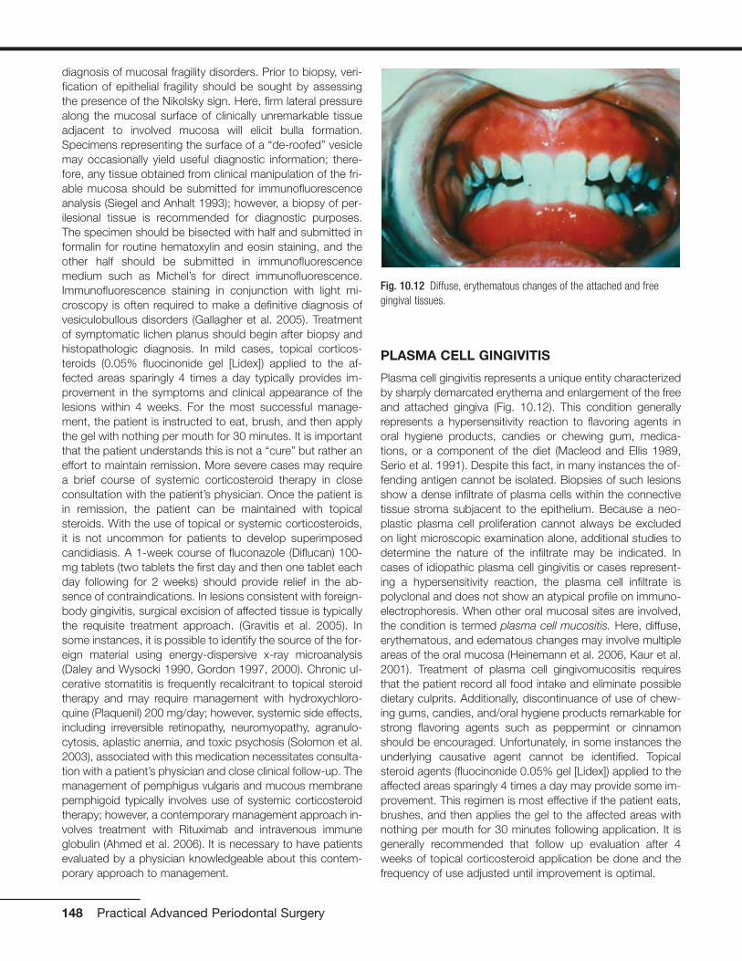
diagnosis of mucosal fragility disorders. Prior to biopsy, veri-fication of epithelial fragility should be sought by assessingthe presence of the Nikolsky sign. Here, firm lateral pressurealong the mucosal surface of clinically unremarkable tissueadjacent to involved mucosa will elicit bulla formation.Specimens representing the surface of a “de-roofed” vesiclemay occasionally yield useful diagnostic information; there-fore, any tissue obtained from clinical manipulation of the fri-able mucosa should be submitted for immunofluorescenceanalysis (Siegel and Anhalt 1993); however, a biopsy of per-ilesional tissue is recommended for diagnostic purposes.The specimen should be bisected with half and submitted informalin for routine hematoxylin and eosin staining, and theother half should be submitted in immunofluorescencemedium such as Michel’s for direct immunofluorescence.Immunofluorescence staining in conjunction with light mi-croscopy is often required to make a definitive diagnosis ofvesiculobullous disorders (Gallagher et al. 2005). Treatmentof symptomatic lichen planus should begin after biopsy andhistopathologic diagnosis. In mild cases, topical corticos-teroids (0.05% fluocinonide gel [Lidex]) applied to the af-fected areas sparingly 4 times a day typically provides im-provement in the symptoms and clinical appearance of thelesions within 4 weeks. For the most successful manage-ment, the patient is instructed to eat, brush, and then applythe gel with nothing per mouth for 30 minutes. It is importantthat the patient understands this is not a “cure” but rather aneffort to maintain remission. More severe cases may requirea brief course of systemic corticosteroid therapy in closeconsultation with the patient’s physician. Once the patient isin remission, the patient can be maintained with topicalsteroids. With the use of topical or systemic corticosteroids,it is not uncommon for patients to develop superimposedcandidiasis. A 1-week course of fluconazole (Diflucan) 100-mg tablets (two tablets the first day and then one tablet eachday following for 2 weeks) should provide relief in the ab-sence of contraindications. In lesions consistent with foreign-body gingivitis, surgical excision of affected tissue is typicallythe requisite treatment approach. (Gravitis et al. 2005). Insome instances, it is possible to identify the source of the for-eign material using energy-dispersive x-ray microanalysis(Daley and Wysocki 1990, Gordon 1997, 2000). Chronic ul-cerative stomatitis is frequently recalcitrant to topical steroidtherapy and may require management with hydroxychloro-quine (Plaquenil) 200 mg/day; however, systemic side effects,including irreversible retinopathy, neuromyopathy, agranulo-cytosis, aplastic anemia, and toxic psychosis (Solomon et al.2003), associated with this medication necessitates consulta-tion with a patient’s physician and close clinical follow-up. Themanagement of pemphigus vulgaris and mucous membranepemphigoid typically involves use of systemic corticosteroidtherapy; however, a contemporary management approach in-volves treatment with Rituximab and intravenous immuneglobulin (Ahmed et al. 2006). It is necessary to have patientsevaluated by a physician knowledgeable about this contem-porary approach to management.
PLASMA CELL GINGIVITIS
Plasma cell gingivitis represents a unique entity characterizedby sharply demarcated erythema and enlargement of the freeand attached gingiva (Fig. 10.12). This condition generallyrepresents a hypersensitivity reaction to flavoring agents inoral hygiene products, candies or chewing gum, medica-tions, or a component of the diet (Macleod and Ellis 1989,Serio et al. 1991). Despite this fact, in many instances the of-fending antigen cannot be isolated. Biopsies of such lesionsshow a dense infiltrate of plasma cells within the connectivetissue stroma subjacent to the epithelium. Because a neo-plastic plasma cell proliferation cannot always be excludedon light microscopic examination alone, additional studies todetermine the nature of the infiltrate may be indicated. Incases of idiopathic plasma cell gingivitis or cases represent-ing a hypersensitivity reaction, the plasma cell infiltrate ispolyclonal and does not show an atypical profile on immuno-electrophoresis. When other oral mucosal sites are involved,the condition is termed plasma cell mucositis. Here, diffuse,erythematous, and edematous changes may involve multipleareas of the oral mucosa (Heinemann et al. 2006, Kaur et al.2001). Treatment of plasma cell gingivomucositis requiresthat the patient record all food intake and eliminate possibledietary culprits. Additionally, discontinuance of use of chew-ing gums, candies, and/oral hygiene products remarkable forstrong flavoring agents such as peppermint or cinnamonshould be encouraged. Unfortunately, in some instances theunderlying causative agent cannot be identified. Topicalsteroid agents (fluocinonide 0.05% gel [Lidex]) applied to theaffected areas sparingly 4 times a day may provide some im-provement. This regimen is most effective if the patient eats,brushes, and then applies the gel to the affected areas withnothing per mouth for 30 minutes following application. It isgenerally recommended that follow up evaluation after 4weeks of topical corticosteroid application be done and thefrequency of use adjusted until improvement is optimal.
148 Practical Advanced Periodontal Surgery
Fig. 10.12 Diffuse, erythematous changes of the attached and freegingival tissues.
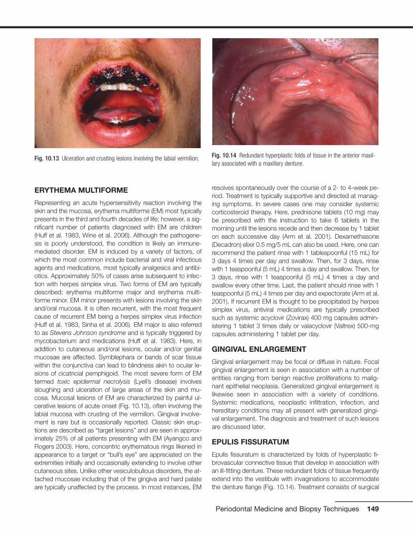
ERYTHEMA MULTIFORME
Representing an acute hypersensitivity reaction involving theskin and the mucosa, erythema multiforme (EM) most typicallypresents in the third and fourth decades of life; however, a sig-nificant number of patients diagnosed with EM are children(Huff et al. 1983, Wine et al. 2006). Although the pathogene-sis is poorly understood, the condition is likely an immune-mediated disorder. EM is induced by a variety of factors, ofwhich the most common include bacterial and viral infectiousagents and medications, most typically analgesics and antibi-otics. Approximately 50% of cases arise subsequent to infec-tion with herpes simplex virus. Two forms of EM are typicallydescribed: erythema multiforme major and erythema multi-forme minor. EM minor presents with lesions involving the skinand/oral mucosa. It is often recurrent, with the most frequentcause of recurrent EM being a herpes simplex virus infection(Huff et al. 1983, Sinha et al. 2006). EM major is also referredto as Stevens Johnson syndrome and is typically triggered bymycobacterium and medications (Huff et al. 1983). Here, inaddition to cutaneous and/oral lesions, ocular and/or genitalmucosae are affected. Symblephara or bands of scar tissuewithin the conjunctiva can lead to blindness akin to ocular le-sions of cicatricial pemphigoid. The most severe form of EMtermed toxic epidermal necrolysis (Lyell’s disease) involvessloughing and ulceration of large areas of the skin and mu-cosa. Mucosal lesions of EM are characterized by painful ul-cerative lesions of acute onset (Fig. 10.13), often involving thelabial mucosa with crusting of the vermilion. Gingival involve-ment is rare but is occasionally reported. Classic skin erup-tions are described as “target lesions” and are seen in approx-imately 25% of all patients presenting with EM (Ayangco andRogers 2003). Here, concentric erythematous rings likened inappearance to a target or “bull’s eye” are appreciated on theextremities initially and occasionally extending to involve othercutaneous sites. Unlike other vesiculobullous disorders, the at-tached mucosae including that of the gingiva and hard palateare typically unaffected by the process. In most instances, EM
resolves spontaneously over the course of a 2- to 4-week pe-riod. Treatment is typically supportive and directed at manag-ing symptoms. In severe cases one may consider systemiccorticosteroid therapy. Here, prednisone tablets (10 mg) maybe prescribed with the instruction to take 6 tablets in themorning until the lesions recede and then decrease by 1 tableton each successive day (Arm et al. 2001). Dexamethasone(Decadron) elixir 0.5 mg/5 mL can also be used. Here, one canrecommend the patient rinse with 1 tablespoonful (15 mL) for3 days 4 times per day and swallow. Then, for 3 days, rinsewith 1 teaspoonful (5 mL) 4 times a day and swallow. Then, for3 days, rinse with 1 teaspoonful (5 mL) 4 times a day andswallow every other time. Last, the patient should rinse with 1teaspoonful (5 mL) 4 times per day and expectorate (Arm et al.2001). If recurrent EM is thought to be precipitated by herpessimplex virus, antiviral medications are typically prescribedsuch as systemic acyclovir (Zovirax) 400 mg capsules admin-istering 1 tablet 3 times daily or valacyclovir (Valtrex) 500-mgcapsules administering 1 tablet per day.
GINGIVAL ENLARGEMENT
Gingival enlargement may be focal or diffuse in nature. Focalgingival enlargement is seen in association with a number ofentities ranging from benign reactive proliferations to malig-nant epithelial neoplasia. Generalized gingival enlargement islikewise seen in association with a variety of conditions.Systemic medications, neoplastic infiltration, infection, andhereditary conditions may all present with generalized gingi-val enlargement. The diagnosis and treatment of such lesionsare discussed later.
EPULIS FISSURATUM
Epulis fissuratum is characterized by folds of hyperplastic fi-brovascular connective tissue that develop in association withan ill-fitting denture. These redundant folds of tissue frequentlyextend into the vestibule with invaginations to accommodatethe denture flange (Fig. 10.14). Treatment consists of surgical
Periodontal Medicine and Biopsy Techniques 149
Fig. 10.13 Ulceration and crusting lesions involving the labial vermilion. Fig. 10.14 Redundant hyperplastic folds of tissue in the anterior maxil-lary associated with a maxillary denture.
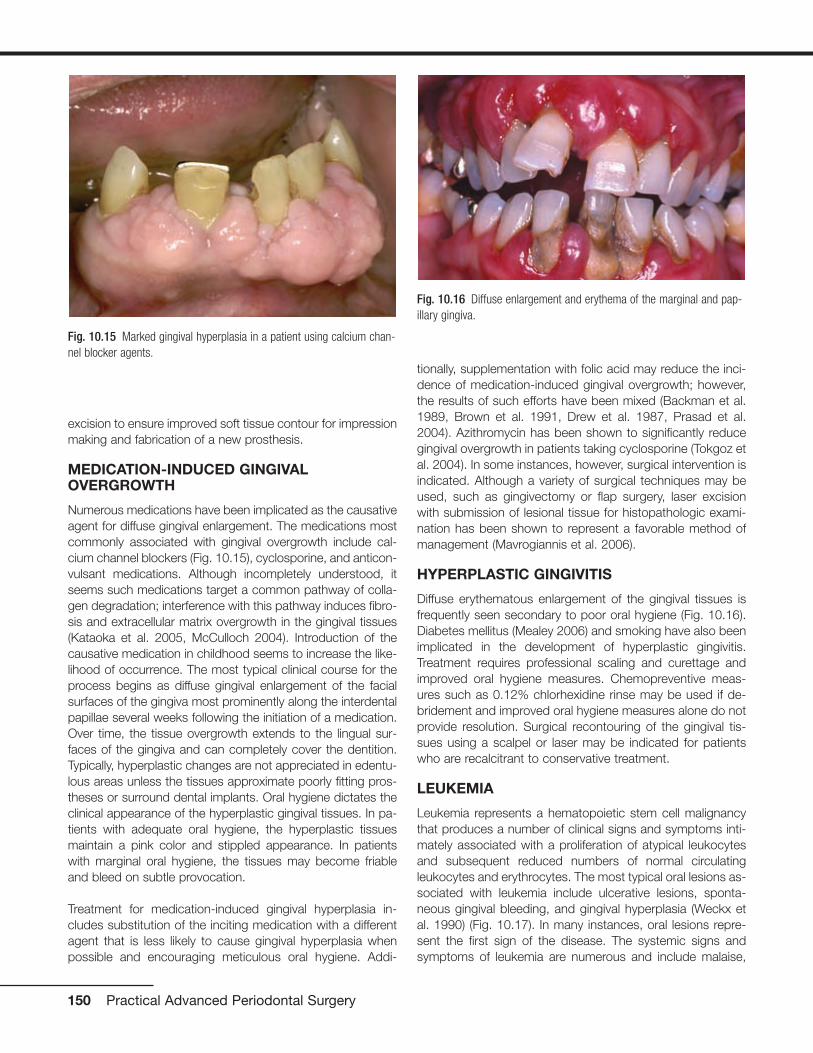
excision to ensure improved soft tissue contour for impressionmaking and fabrication of a new prosthesis.
MEDICATION-INDUCED GINGIVALOVERGROWTH
Numerous medications have been implicated as the causativeagent for diffuse gingival enlargement. The medications mostcommonly associated with gingival overgrowth include cal-cium channel blockers (Fig. 10.15), cyclosporine, and anticon-vulsant medications. Although incompletely understood, itseems such medications target a common pathway of colla-gen degradation; interference with this pathway induces fibro-sis and extracellular matrix overgrowth in the gingival tissues(Kataoka et al. 2005, McCulloch 2004). Introduction of thecausative medication in childhood seems to increase the like-lihood of occurrence. The most typical clinical course for theprocess begins as diffuse gingival enlargement of the facialsurfaces of the gingiva most prominently along the interdentalpapillae several weeks following the initiation of a medication.Over time, the tissue overgrowth extends to the lingual sur-faces of the gingiva and can completely cover the dentition.Typically, hyperplastic changes are not appreciated in edentu-lous areas unless the tissues approximate poorly fitting pros-theses or surround dental implants. Oral hygiene dictates theclinical appearance of the hyperplastic gingival tissues. In pa-tients with adequate oral hygiene, the hyperplastic tissuesmaintain a pink color and stippled appearance. In patientswith marginal oral hygiene, the tissues may become friableand bleed on subtle provocation.
Treatment for medication-induced gingival hyperplasia in-cludes substitution of the inciting medication with a differentagent that is less likely to cause gingival hyperplasia whenpossible and encouraging meticulous oral hygiene. Addi-
tionally, supplementation with folic acid may reduce the inci-dence of medication-induced gingival overgrowth; however,the results of such efforts have been mixed (Backman et al.1989, Brown et al. 1991, Drew et al. 1987, Prasad et al.2004). Azithromycin has been shown to significantly reducegingival overgrowth in patients taking cyclosporine (Tokgoz etal. 2004). In some instances, however, surgical intervention isindicated. Although a variety of surgical techniques may beused, such as gingivectomy or flap surgery, laser excisionwith submission of lesional tissue for histopathologic exami-nation has been shown to represent a favorable method ofmanagement (Mavrogiannis et al. 2006).
HYPERPLASTIC GINGIVITIS
Diffuse erythematous enlargement of the gingival tissues isfrequently seen secondary to poor oral hygiene (Fig. 10.16).Diabetes mellitus (Mealey 2006) and smoking have also beenimplicated in the development of hyperplastic gingivitis.Treatment requires professional scaling and curettage andimproved oral hygiene measures. Chemopreventive meas-ures such as 0.12% chlorhexidine rinse may be used if de-bridement and improved oral hygiene measures alone do notprovide resolution. Surgical recontouring of the gingival tis-sues using a scalpel or laser may be indicated for patientswho are recalcitrant to conservative treatment.
LEUKEMIA
Leukemia represents a hematopoietic stem cell malignancythat produces a number of clinical signs and symptoms inti-mately associated with a proliferation of atypical leukocytesand subsequent reduced numbers of normal circulatingleukocytes and erythrocytes. The most typical oral lesions as-sociated with leukemia include ulcerative lesions, sponta-neous gingival bleeding, and gingival hyperplasia (Weckx etal. 1990) (Fig. 10.17). In many instances, oral lesions repre-sent the first sign of the disease. The systemic signs andsymptoms of leukemia are numerous and include malaise,
150 Practical Advanced Periodontal Surgery
Fig. 10.15 Marked gingival hyperplasia in a patient using calcium chan-nel blocker agents.
Fig. 10.16 Diffuse enlargement and erythema of the marginal and pap-illary gingiva.
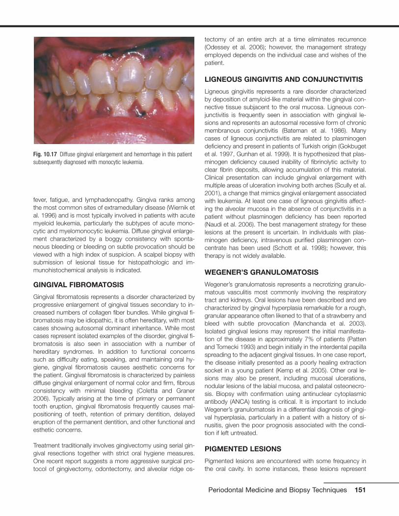
fever, fatigue, and lymphadenopathy. Gingiva ranks amongthe most common sites of extramedullary disease (Wiernik etal. 1996) and is most typically involved in patients with acutemyeloid leukemia, particularly the subtypes of acute mono-cytic and myelomonocytic leukemia. Diffuse gingival enlarge-ment characterized by a boggy consistency with sponta-neous bleeding or bleeding on subtle provocation should beviewed with a high index of suspicion. A scalpel biopsy withsubmission of lesional tissue for histopathologic and im-munohistochemical analysis is indicated.
GINGIVAL FIBROMATOSIS
Gingival fibromatosis represents a disorder characterized byprogressive enlargement of gingival tissues secondary to in-creased numbers of collagen fiber bundles. While gingival fi-bromatosis may be idiopathic, it is often hereditary, with mostcases showing autosomal dominant inheritance. While mostcases represent isolated examples of the disorder, gingival fi-bromatosis is also seen in association with a number ofhereditary syndromes. In addition to functional concernssuch as difficulty eating, speaking, and maintaining oral hy-giene, gingival fibromatosis causes aesthetic concerns forthe patient. Gingival fibromatosis is characterized by painlessdiffuse gingival enlargement of normal color and firm, fibrousconsistency with minimal bleeding (Coletta and Graner2006). Typically arising at the time of primary or permanenttooth eruption, gingival fibromatosis frequently causes mal-positioning of teeth, retention of primary dentition, delayederuption of the permanent dentition, and other functional andesthetic concerns.
Treatment traditionally involves gingivectomy using serial gin-gival resections together with strict oral hygiene measures.One recent report suggests a more aggressive surgical pro-tocol of gingivectomy, odontectomy, and alveolar ridge os-
tectomy of an entire arch at a time eliminates recurrence(Odessey et al. 2006); however, the management strategyemployed depends on the individual case and wishes of thepatient.
LIGNEOUS GINGIVITIS AND CONJUNCTIVITIS
Ligneous gingivitis represents a rare disorder characterizedby deposition of amyloid-like material within the gingival con-nective tissue subjacent to the oral mucosa. Ligneous con-junctivitis is frequently seen in association with gingival le-sions and represents an autosomal recessive form of chronicmembranous conjunctivitis (Bateman et al. 1986). Manycases of ligneous conjunctivitis are related to plasminogendeficiency and present in patients of Turkish origin (Gokbugetet al. 1997, Gunhan et al. 1999). It is hypothesized that plas-minogen deficiency caused inability of fibrinolytic activity toclear fibrin deposits, allowing accumulation of this material.Clinical presentation can include gingival enlargement withmultiple areas of ulceration involving both arches (Scully et al.2001), a change that mimics gingival enlargement associatedwith leukemia. At least one case of ligneous gingivitis affect-ing the alveolar mucosa in the absence of conjunctivitis in apatient without plasminogen deficiency has been reported(Naudi et al. 2006). The best management strategy for theselesions at the present is uncertain. In individuals with plas-minogen deficiency, intravenous purified plasminogen con-centrate has been used (Schott et al. 1998); however, thistherapy is not widely available.
WEGENER’S GRANULOMATOSIS
Wegener’s granulomatosis represents a necrotizing granulo-matous vasculitis most commonly involving the respiratorytract and kidneys. Oral lesions have been described and arecharacterized by gingival hyperplasia remarkable for a rough,granular appearance often likened to that of a strawberry andbleed with subtle provocation (Manchanda et al. 2003).Isolated gingival lesions may represent the initial manifesta-tion of the disease in approximately 7% of patients (Pattenand Tomecki 1993) and begin initially in the interdental papillaspreading to the adjacent gingival tissues. In one case report,the disease initially presented as a poorly healing extractionsocket in a young patient (Kemp et al. 2005). Other oral le-sions may also be present, including mucosal ulcerations,nodular lesions of the labial mucosa, and palatal osteonecro-sis. Biopsy with confirmation using antinuclear cytoplasmicantibody (ANCA) testing is critical. It is important to includeWegener’s granulomatosis in a differential diagnosis of gingi-val hyperplasia, particularly in a patient with a history of si-nusitis, given the poor prognosis associated with the condi-tion if left untreated.
PIGMENTED LESIONS
Pigmented lesions are encountered with some frequency inthe oral cavity. In some instances, these lesions represent
Periodontal Medicine and Biopsy Techniques 151
Fig. 10.17 Diffuse gingival enlargement and hemorrhage in this patientsubsequently diagnosed with monocytic leukemia.

generalized or diffuse changes; in other instances, the pig-mented change is focal in nature.
PHYSIOLOGIC PIGMENTATION
Most commonly noted on attached gingiva in darker-skinnedpatients, physiologic pigmentation presents as a diffusebrown-black pigmentation secondary to increasedmelanocyte activity. Here, pigmentation develops during thefirst two decades of life. Physiologic pigmentation is typicallybilaterally symmetrical in distribution and most prominentalong the labial attached gingiva in the region of the maxillaryand mandibular incisors. The distribution is likened to aribbon-like band that spares the marginal gingiva (Eisen 2000)(Fig. 10.18). Pigmentation may also be appreciated within thebuccal mucosa, lips, tongue (particularly of the fungiformpapillae), and hard palate and is notable for a macular appear-ance with indistinct borders (Kauzman et al. 2004). Althoughphysiologic pigmentation is not a medical concern, recentpublications suggest social pressures influence some patientsto request gingival depigmentation for esthetic purposes (Talet al, Oegiesser and Ta. 2003). The most significant factor forclinicians is to recognize the entity as a normal manifestationas opposed to a pathologic process.
MEDICATION-INDUCED PIGMENTATION
Drug-induced discoloration of the oral mucosa is caused byan increasing number of medications. The discoloration canoccur after direct contact with the medication or following itssystemic absorption. In some instances, medication stimu-lates melanocytes to increase melanin production; in other in-stances, medication causes formation of metabolites that arethought to be the cause of increased pigmentation.Medications typically associated with pigmentation of the oralmucosa include minocycline (Fig. 10.19), antimalarial med-ications, estrogens, tranquilizers, phenolphthalein found in
laxatives, chemotherapy medications, and medications usedto manage patients with HIV infection (Abdollahi and Radfar2003). In some instances, discoloration caused by medica-tion resolves in the weeks following discontinuation of themedication; however, in some instances, the change is per-manent. Many accounts of exposure to metals such as gold,lead, mercury, and silver have been historically documentedin the literature with a classic presentation of linear pigmenta-tion following the gingival margins described. Other presen-tations of drug-induced pigmentation vary but include diffusepigmentation of the palate and rare descriptions of pigmen-tation changes of the soft tissues of the lips, tongue, eyes,and perioral skin.
Antimalarial agents are typically linked to discoloration of thepalate; minocycline use is frequently associated with palataland occasionally skin lesions (Treister et al. 2004); phenolph-thalein is associated with well-circumscribed macular pig-mented lesions of the skin and mucosa; and estrogens areassociated with diffuse melanosis and most typically seen infemale patients. In some instances, a biopsy may be indi-cated to confirm the diagnosis and rule out the presence ofunderlying melanocytic pathology.
SMOKER’S MELANOSIS
Smoker’s melanosis represents diffuse benign pigmentation ofthe oral mucosa, particularly noted on the anterior facial at-tached gingiva (Axell and Hedin 1982, Hedin 1977) (Fig.10.20). Typically, the distribution of pigmented changes beginsin the interdental papilla region and may extend to form con-tinuous ribbons involving the anterior attached gingiva with theapical extension of the lesions not exceeding the mucogingi-val junction (Hedin 1977). Unlike physiologic pigmentation,smoker’s melanosis does not spare the marginal gingiva, is ofrecent onset, and increases in intensity and number of lesions
152 Practical Advanced Periodontal Surgery
Fig. 10.18 Band-like pigmentation of the attached gingiva. (Image cour-tesy of Dr. Helen Santis.)
Fig. 10.19 Pigmentation of the gingiva associated with use of mino-cycline.

with an increase in the number of cigarettes used daily. In pa-tients who consume alcohol in addition to smoking, areas oforal depigmentation surrounded by hyperpigmentation arefrequently noted (Natali et al. 1991). In a study of dark-skinnedpatients, while most non–tobacco users exhibited some levelof physiologic oral melanin pigmentation, tobacco smokershad significantly more oral surfaces pigmented than did thenon–tobacco users (Ramer and Burakoff 1997). Reports havebeen described of reduction in smoking leading to the disap-pearance of smoking-induced melanosis (Hedin et al. 1993).Given that these lesions present in patients in adulthood andoften darken progressively over time, biopsy is often indicatedto rule out melanoma. (Portions reprinted with permissionfrom the Journal of the Massachusetts Dental Society 2007Spring;in press).
AMALGAM TATTOO
An amalgam tattoo typically presents as a gray-blue macularlesion of the oral mucosa that occurs following implantationof dental amalgam into the oral soft tissues (Fig. 10.21).Common clinical scenarios associated with this phenomenoninclude introduction of amalgam into the oral soft tissues byhigh-speed hand pieces, contamination of extraction siteswith amalgam debris, and linear impregnation of interdentaltissues with amalgam-laden dental floss following restorativeprocedures (Mirowski and Waibel 2002). Small radiopaqueparticles may be evident on radiographic examination to cor-roborate the clinical impression; however, the metallic parti-cles are often too small to be appreciated. Over time, anamalgam tattoo may appear to enlarge as the amalgam-carrying macrophages migrate away from the initial site of im-plantation. In some individuals, an inflammatory response tothe amalgam may be accompanied by clinical discomfort thatwould predicate the need for biopsy. When a suspectedamalgam tattoo presents in an unusual location, a biopsy
may be indicated to exclude other pigmented lesions such asmelanoacanthoma and melanoma. (Portions reprinted withpermission from the Journal of the Massachusetts DentalSociety 2005 Spring;54(1):55).
MELANOTIC MACULE
The oral melanotic macule is a frequently encountered pig-mented lesion of the oral mucosa. Typically found on thelower labial vermilion, buccal mucosa, gingiva, and palate,the oral melanotic macule is characterized as a solitary, well-demarcated, uniformly pigmented, macular brown lesion (Fig.10.22). Although exposure to ultraviolet radiation can clearlybe excluded as a causative agent in intraoral lesions, the re-lationship between lesions of the lower labial vermillion andsun exposure is unclear. While the oral melanotic macule is
Periodontal Medicine and Biopsy Techniques 153
Fig. 10.20 Diffuse pigmentation of the anterior attached gingiva in aheavy smoker. (Image courtesy of Dr. Brad Neville.)
Fig. 10.21 Multifocal areas of mucosal pigmentation at the apices ofteeth treated with apical retrofill procedures. (Image courtesy of Dr. HelenSantis.)
Fig. 10.22 Well-demarcated brown macular lesion of the lower labialmucosa.

generally not regarded as a lesion with potential to undergomalignant transformation, rare examples of malignant trans-formation have been reported in the literature (Kahn et al.2005). Given the predilection for melanoma to present on thegingiva and palate, lesions presenting in these locationsshould be viewed with a high index of suspicion. Additionally,features such as asymmetry and color variegation are worri-some. Because malignancy cannot always be excluded onclinical presentation alone, an excisional biopsy may be indi-cated with submission of lesional tissue for histopathologicevaluation.
ORAL MELANOACANTHOMA(MELANOACANTHOSIS)
Oral melanoacanthoma represents an acquired melanocyticpigmentation that arises suddenly and most likely representsa reactive phenomenon. Presenting most frequently in blackfemales, the lesion is characterized by a brown-black ap-pearance exhibiting a smooth to somewhat raised surfacecontour (Fig. 10.23). Typically found on the buccal mucosa,oral melanoacanthoma has been reported to arise on the lip,palate, and gingiva (Flaitz 2000). As the lesion arises sud-denly with marked growth potential, melanoacanthoma can-not be differentiated from other melanocytic lesions withoutbiopsy. Distinctive histopathologic features particularly thepresence of dendritic melanocytes within the epithelial spin-ous cell layer differentiates melanoacanthoma from othermelanocytic lesions. Once definitive diagnosis is made, fur-ther treatment is unnecessary. Although rare, cases of spon-taneous resolution of oral melanoacanthoma have been re-ported (Fatahzadeh and Sirois 2002, Wright 1988).
ORAL MELANOCYTIC NEVUS
Oral melanocytic nevi typically present as well-circumscribedpapules that range in color from brown to black and may be
devoid of pigmentation (Fig. 10.24). The most common loca-tions for melanocytic nevi in the oral cavity include the buccalmucosa, gingiva, lips, and palate (Buchner and Hansen1987, 1987). One form of melanocytic nevus termed the bluenevus typically presents on the palate (Buchner and Hansen1987, 1987). Oral melanocytic nevi are somewhat more com-mon in women and occur over a wide age range, with mostlesions noted in the third to fourth decades of life (Buchner etal. 2004). Although the malignant transformation potential oforal mucosal melanoma is not proved, given that oralmelanocytic nevi frequently present on the palate, similar tooral mucosal melanoma, and are relatively uncommon le-sions, excision with submission of lesional tissue forhistopathologic evaluation is recommended.
ORAL MELANOMA
Typically occurring on the palate, maxillary gingiva, and max-illary alveolar mucosa (Barker et al. 1997), oral melanomarepresents an uncommon malignancy of the oral cavity. The5-year survival rate for oral melanoma persists unchangedsince initially being reported in the literature and ranges from10% to 20% (Eisen and Voorhees 1991). Oral melanomapresents as pigmented plaques remarkable for irregularasymmetric borders exhibiting brown-black coloration (Fig.10.25). Some melanomas are notable for lack of melanocyticpigmentation (Eisen and Voorhees 1991). Clinical evidence ofulceration, bone erosion, or frank invasion of bone is not un-common. When intraoral melanoma represents metastaticrather than a primary oral lesion, such lesions typically pre-sent on the buccal mucosa, tongue, and at the site of a non-healing extraction socket (Patton et al. 1994). Given that theprognosis of oral melanoma depends on the stage of the dis-ease at the time of diagnosis and that the depth of most orallesions at the time of diagnosis is advanced, early detectionis critical. Pigmented lesions with irregular borders presenting
154 Practical Advanced Periodontal Surgery
Fig. 10.23 Smooth pigmented lesion of recent onset of the posteriorbuccal mucosa.
Fig. 10.24 Slightly raised pigmented lesion of the posterior hard palate.

on the palate or maxillary gingiva or alveolar mucosa shouldbe viewed with suspicion. Treatment typically involves radicalsurgical excision together with neck dissection and adjuvantchemotherapy (Umeda and Shimada 1994).
SANGUINARIA-INDUCED LEUKOPLAKIA
Exposure of the oral cavity to chemical substances, medica-tions, or dentifrice can lead to specific mucosal changes.Chronic use of mouth rinses containing sanguinaria extract(also known as bloodroot extract) has been shown to pro-duce leukoplakic lesions with an implied potential for malig-nant transformation (Damm et al. 1999). The use of Viadentbrand mouth rinse (Colgate Oral Pharmaceuticals, Canton,MA) containing sanguinaria extract, a product of the blood-root plant, has been shown to produce leukoplakic lesions ofthe maxillary vestibule, a site that is uncommon for white le-sions (Fig. 10.26). It is generally recognized that these lesionsfrequently persist and even recur following discontinuation ofthe product. Because biopsy may show areas of mild tomoderate epithelial dysplasia, these patients need to be keptunder close surveillance (Eversole et al. 2000). Given the ap-parent association between sanguinaria-containing dentifriceand dysplastic leukoplakia, it is recommended individualspresenting with leukoplakic lesions and history of exposure toViadent submit for biopsy and discontinue use of the product(Damm et al. 1999). (Portions reprinted with permissionpending from Otolaryngol Clin N Am (38)2005 21-35).
PROLIFERATIVE VERRUCOUS LEUKOPLAKIA
One particularly persistent and importunate form of leuko-plakia can be difficult to distinguish from verrucous carci-noma. Proliferative verrucous leukoplakia (PVL) is character-ized as an extensive exophytic papillary proliferation thatoften involves multiple sites and is recalcitrant to treatment.
Initial PVL lesions present in a solitary fashion characterizedby thin hyperkeratosis and are well delineated from the sur-rounding mucosa. As the lesion evolves, it may develop aperceptually thickened quality with superficial undulationsconsistent with verrucous hyperplasia. The lesions becomemultifocal and recur following excision. Over time, the lesionsprogress to verrucous carcinoma or squamous cell carci-noma (Hansen et al. 1985).
Unique in its predilection for women nearly 4:1 over men, PVLis generally diagnosed in the seventh decade of life. Studiesreport from 70% to nearly 100% of PVL lesions progress tosquamous cell carcinoma (Batsakis et al. 1999, Silvermanand Gorsky 1997), with the gingiva and tongue being thesites showing the highest incidence of transformation(Silverman and Gorsky 1997). Months to years may transpirefrom the time of initial recognition of the process to its ulti-mate transformation to invasive carcinoma. No apparent linkbetween use of tobacco products has been firmly estab-lished with regard to PVL (Fettig et al. 2000, Silverman andGorsky 1997), and the link between human papilloma virusand PVL is controversial (Bagan et al. 2007, Palefsky et al.1995). Given that PVL most likely represents a disease that ismultifactorial in nature, it is difficult to anticipate specificallywho is at high risk for developing the condition. (Portionsreprinted with permission pending from Otolaryngol Clin NAm (38)2005 21-35).
MALIGNANT NEOPLASIA
Malignant neoplasia involving the oral cavity may representprimary disease or metastasis, particularly from the breast,lung, kidney, prostate, gastrointestinal tract, and thyroid gland.
Periodontal Medicine and Biopsy Techniques 155
Fig. 10.25 Irregular pigmented lesion of the posterior palate.
Fig. 10.26 White plaque of the maxillary mucobuccal fold.

SQUAMOUS CELL CARCINOMA
Oral squamous cell carcinoma represents the most commonintraoral malignancy and is remarkable for a variety of clinicalpresentations ranging from erythroplakia to leukoplakia, or itmay present as a combination of the two. Incipient lesionsare typically painless; however, as the lesion progresses,areas of ulceration and induration may be seen and the lesionmay become more nodular. Fixation to underlying tissues andlocal-regional lymph node metastasis indicate further pro-gression to an intermediate stage of malignancy. Late-stagelesions may present with bony involvement, tooth mobility,pain, and paresthesia (Zakrzewska 1999).
All forms of tobacco use are associated with an increasedrisk of developing oral squamous cell carcinoma. When com-bined, tobacco and alcohol work in synergy to potentiate theincreased risk of developing invasive tumor (Scully and Porter2000, Zakrzewska 1999). Additionally, exposure to ultravioletradiation (lip) or betel quid (a mixture of slaked lime, arecanut, and tobacco wrapped in betel leaf and chewed—a so-cial habit quite prevalent in the Indian subcontinent) may pre-dispose susceptive individuals to submucous fibrosis, a con-dition that has an approximately 17% chance of malignanttransformation and immunosuppression; these are well-recognized etiologic factors that when paired with a geneti-cally susceptible individual may yield transformation to oralsquamous cell carcinoma (Scully and Porter 2000).
The most common sites for oral squamous cell carcinomaare the posterior lateral and ventral tongue, floor of themouth, and soft palate, although gingival lesions are also re-ported (Seoane et al. 2006) (Fig. 10.27). In some instances,the similarities between gingival squamous cell carcinomaand periodontal disease may lead to a delay in diagnosis. Theprognosis for oral squamous cell carcinoma is largely basedon the stage of presentation (Sanderson and Ironside 2002)and the lesion’s location. The presence of positive nodal in-volvement reduces long-term survival by as much as 50%(Sanderson and Ironside 2002).
Clinical presentations that warrant immediate action to ruleout squamous cell carcinoma include nonhealing ulcerationor unexplained swelling of approximately 3 weeks’ durationand all red and/or white lesions. A biopsy is mandatory withdefinitive diagnosis via histolopathologic examination. Addi-tionally, it is recommended that tooth mobility unrelated toperiodontal disease receive thorough investigation (Sander-son and Ironside 2002).
Early biopsy is recommended for any nonhealing or slowly re-solving lesion even if the patient is young and/or denies expo-sure to tobacco products. Although extremely rare, occa-sional accounts of squamous cell carcinoma arising inpediatric patients have been made (Bill et al. 2001). Addi-tionally, recent reports have shown an increased incidence of
squamous cell carcinoma in female patients and in those pa-tients younger than 40 years (Martin-Granizo et al. 1997).Ultimately, despite advances in treatment, prognosis dependsheavily on tumor staging at the time of presentation. Thoroughclinical examination and a high index of suspicion for mucosalalterations at high-risk sites provide the best chance for a pos-itive outcome. (Portions reprinted with permission pendingfrom Otolaryngol Clin N Am (38)2005 21-35).
VERRUCOUS CARCINOMA
Verrucous carcinoma represents a low-grade variant of squa-mous cell carcinoma with a characteristic papillary exophyticgrowth pattern (Fig. 10.28). A superficial insidious neoplasmprincipally due to its indolent growth course, verrucous carci-noma can be extensive and multifocal at the time of clinicalpresentation. Within the oral cavity, the most common sitesof occurrence are the buccal mucosa and gingiva, sites typi-cally not considered “high risk” with regard to traditionalsquamous cell carcinoma (Koch et al. 2001).
Although verrucous carcinoma is not confined exclusively inpresentation to the upper aerodigestive tract, a significant link between oral verrucous carcinoma and tobacco prod-ucts has been made (Ferlito and Recher 1980, Medina et al.1984, Spiro 1998). Surgical excision is advocated as thestandard of care for treatment, and many years of follow-upare required to capture additional foci, as dictated by themulticentric nature of the process and apparent increasedlikelihood that recurrent lesions may prove to be more poorlydifferentiated than their predecessor (Ferlito and Recher1980, Medina et al. 1984, Spiro 1998). Further, studies havereported a near 20% incidence of squamous cell carcinomaarising in lesions of verrucous carcinoma. Clinical distinction
156 Practical Advanced Periodontal Surgery
Fig. 10.27 Exophytic erythroleukoplakic lesion of the anterior maxillarygingiva.

cannot be made between traditional verrucous carcinomalesions and those containing foci of invasive squamous cellcarcinoma (Medina et al. 1984). This finding dictates thor-ough surgical excision extending deep into connective tissueto allow adequate assessment of the epithelial–connectivetissue interface histologically and that multiple levels throughthe specimen be subjected to histologic evaluation. Given the propensity for verrucous carcinoma lesions to grow in aslow fashion, adequate surgical excision coupled with rigor-ous clinical follow-up provides the most optimistic prog-nosis (McCoy and Waldron 1981). (Portions reprinted withpermission pending from Otolaryngol Clin N Am (38)2005 21-35).
METASTATIC DISEASE
Although metastatic disease is uncommon in the oral cavity,representing less than 1% of oral neoplasia (van der Waal etal. 2003), in at least one third of patients, metastasis to thejawbones or oral soft tissues represents the first clinical signof the disease (D’Silva et al. 2006, Hirshberg and Buchner1995, van der Waal et al. 2003). Of lesions inclined to metas-tasize to the oral soft tissues, metastatic disease from thelung is the most commonly encountered (Hirshberg andBuchner 1995). When lesions metastasize to the gingiva, le-sions typically present as polypoid masses that may be mis-taken for a benign reactive gingival nodule (Ramon Ramirezet al. 2003) (Fig. 10.29), and the most common primary tu-mors to metastasize to the gingiva are those originating inthe lung, kidney, breast, bone, and liver (Elkhoury et al.2004). Obviously, it is of utmost importance to distinguishmetastatic disease from benign lesions that can share simi-lar clinical features. Biopsy with submission of lesional tissuefor histopathologic analysis is important to ensure the bestprognosis.
INFECTIONS
The oral cavity is susceptible to infections with fungal, bac-terial and viral organisms. Infections with herpes simplexvirus and/oral manifestations of HIV infection are discussedlater.
HERPES
Primary herpetic infection typically presents as gingivosto-matitis with the recurrence manifesting as cutaneous/mucocutaneous disease. Symptoms of primary herpeticstomatitis arise after an incubation period of up to 3 weeksfollowing infection. The prodromal symptoms are not patho-gnomonic and include malaise, fever, headache, nausea,anorexia, and irritability. Acute onset of pain in the oral cavityis seen with the development of numerous small vesicular le-sions that quickly coalesce and ulcerate. These lesions mayinvolve any area of the oral cavity, including the gingiva, buc-cal mucosa, tongue, palatal mucosa, vermillion, perioral skin,and oropharynx. A severe complication of primary herpeticgingivostomatitis is ocular involvement. After initial infection,oral herpes simplex virus remains latent in the trigeminal gan-glion. Upon activation, the virus utilizes the axons of sensoryneurons as a means to reach overlying tissues. Symptomaticrecurrences are common and can be preceded by a pro-drome of “tingling” or discomfort in the affected region,sometimes initially mistaken for a toothache. The typical clin-ical presentation for recurrent intraoral herpetic infection is ofmultiple “punched-out” painful areas of ulceration that maycoalesce and often follow the distribution of the greater pala-tine nerve. Recurrences are frequently attributed to manipu-lation of oral tissues during routine dental procedures. Thedistinction between recurrent herpetic lesions and recurrentapthous stomatitis (canker sores) is that herpetic ulcerations
Periodontal Medicine and Biopsy Techniques 157
Fig. 10.29 Metastatic melanoma to the anterior maxillary gingiva.Fig. 10.28 Extensive exophytic white papillary lesion involving the eden-tulous maxillary alveolar ridge and vestibule.

typically involve keratinized tissues (Fig. 10.30) and recurrentapthous ulcerations are seen on moveable mucosa.Systemic antiviral therapy is generally accepted as being ef-fective for management of primary herpetic stomatitis usingacyclovir (Zovirax) 200-mg capsules administering 1 capsule5 times a day for 5 to 7 days; however, the effectiveness ofother antiviral medications such as famciclovir or valaciclovirhas not been fully evaluated (Arduino and Porter 2006).Further, the optimal timing of initiating therapy and optimumdose are not fully defined. Reduction of clinical signs and pa-tient symptoms has been reported for recurrent herpeticstomatitis using acyclovir (Zovirax) cream (5%) one applica-tion topically every 3 to 4 hours for 5 days and penciclovir(Denavir) cream (1%) every 2 hours for 5 days, but studies arestill needed to determine which is more effective (Arduino andPorter 2006). A recent report advocates the utility of oral fam-ciclovir (Famvir) in the management of herpes labialis(Spruance et al. 2006). Here, 1500 mg is taken within 1 hourof the onset of prodromal symptoms. This protocol was re-ported to reduce duration of symptoms by approximately 2days. In immunocompromised patients, topical therapeuticsoffer little benefit. Acyclovir remains the medication of choice(Arduino and Porter 2006). As self-inoculation is possible, it isrecommended patients be advised to avoid touching the le-sions and then touching the eyes, genitalia, or other bodyareas to prevent infection at new sites. (Portions reprintedwith permission from the Journal of the MassachusettsDental Society 2005 Winter; 53(4):55).
HIV-ASSOCIATED GINGIVITIS
Initially termed “HIV-related gingivitis,” linear gingival ery-thema presents as a red band involving the free gingival mar-
gin. This change is typically most prominent in the region ofthe anterior dentition but extends to involve the posteriorquadrants with some frequency (Reznik 2005). Mild bleedingon subtle provocation has been reported, and efforts at im-proved oral hygiene do not lead to resolution. Some reportssuggest this pattern of gingivitis represents a form of candidi-asis (Velegraki et al. 1999). Lesions typically resolve followingprofessional plaque removal and rinses with a 0.12% sus-pension of chlorhexidine gluconate twice per day for 2weeks. Additional HIV-related conditions involving the gingivainclude necrotizing ulcerative gingivitis (NUG) involving necro-sis of one or more interdental papillae and necrotizing ulcer-ative periodontitis with features of NUG in addition to rapidlyprogressing loss of periodontal attachment. Treatment forthese conditions includes gentle debridement with povidone-iodine irrigation. The standard management approach in-cludes rinsing with a suspension of 0.12% chlorhexidine.Follow-up with additional debridement at 24 hours and againevery 7 to 10 days is required. In the acute phase with sys-temic symptoms of fever and malaise, antibiotic therapy is in-dicated (amoxicillin 2 g a day for 7 days or metronidazole).
ORAL SOFT TISSUE BIOPSY TECHNIQUES
It is usually prudent to recommend a biopsy on lesions thathave persisted for over 2 weeks after the removal of a poten-tial irritant. Lesions that are related to infection, inflammation,or local trauma may resolve during this time.
Biopsies can be incisional or excisional depending on the na-ture of the lesion and the comfort level and skills of the prac-titioner. If the lesion is large or malignancy is suspected, anincisional biopsy is indicated in order to not compromise thedefinitive treatment of the potentially malignant lesion. If thelesion is benign, located away from vital structures and ofsmall diameter (less than 1 cm), an excisional biopsy couldbe recommended. In both cases, it is important to includesome of the surrounding healthy tissue in the biopsy speci-men. The incision should be made parallel to the normalcourse of nerves, arteries, and veins to minimize injury (Ellis2003). Also, when opting for an incisional biopsy you shouldkeep in mind that “deeper is better” and it is much better totake a deep, narrow biopsy rather than a broad, shallow onein order to not miss the cellular changes at the base of the le-sion (Ellis 2003). Because of the size and morphology of thelesion requiring an incisional approach, it is sometimes nec-essary to obtain more than one biopsy sample of the samelesion (different locations).
The following methods are used to collect tissue samplesfrom the oral cavity (Campisi et al. 2003, Ellis 2003). • Needle biopsy
• Tissue punch biopsy
• Scalpel biopsy
• Laser biopsy
158 Practical Advanced Periodontal Surgery
Fig. 10.30 Multiple painful punctate areas of ulceration involving themaxillary attached gingiva.

This chapter will be limited to describing techniques usingscalpel biopsy.
ARMAMENTARIUM
Surgical set that is recommended is given in PracticalPeriodontal Plastic Surgery (Dibart and Karima).
INCISIONAL SCALPEL BIOPSY
After proper local anesthesia is achieved by infiltrating thearea 1 cm peripheral to the lesion with xylocaine 2% with1:100,000 epinephrine, the surgeon focuses on the areawhere the incision will take place. With a No. 15 blade, asmall wedge that is approximately 3 mm deep, 5 mm long,and 3 mm wide is excised. The specimen needs to include aportion of the margin as well as some healthy tissue. Thespecimen is then very delicately transferred to a biopsy con-tainer with 10% formalin. It is very important not to crush thetissues during excision or transfer into the fixative solution asthat may interfere with the proper oral pathology diagnosis.The surgical site can be closed with a single suture; the pa-tient is given some mild analgesics (acetaminophen 500 mg)and advised to rinse with an antiseptic mouthwash (chlorhex-idine 0.12%) for 1 week.
EXCISIONAL SCALPEL BIOPSY
After proper local anesthesia is achieved by infiltrating thearea 1 cm peripheral to the lesion with xylocaine 2% with1:100,000 epinephrine, an elliptical incision is made aroundthe lesion with the blade angled toward the lesion (Fig.10.31). Tissue stabilization and hemostasis can be achievedmanually (assistant’s fingers pinching the soft tissue on bothsides of the biopsy) or mechanically by using a clamp (i.e.,Chalazion clamp for a biopsy of the lip) (Fig. 10.32). Again, itis important to remember to remove some healthy tissue withthe specimen. The rule of thumb for easy closure is to havean ellipse that is 3 times longer than wide. Also, dependingon the location of the biopsy site and the size of the wound,there may be a need to undermine the mucosa (with scissors)in order to obtain tension-free closure. Primary closure of anelliptic wound is easily achieved provided that the margins ofthe wound are gently undermined.
Elliptical incisions on the attached gingiva or palate are notsutured but are left to heal by secondary intention. The ex-cised specimen is then very delicately transferred to a biopsycontainer with 10% formalin for fixation (Fig. 10.33). Again, itis very critical not to crush the tissues during excision ortransfer into the fixative solution as that may interfere with theproper oral pathology diagnosis.
The patient is given some mild analgesics (acetaminophen500 mg) and advised to rinse with an antiseptic mouthwash(chlorhexidine 0.12%) for 1 week.
Periodontal Medicine and Biopsy Techniques 159
Fig. 10.31 Excisional biopsy. Notice the angulation of the blade, whichwill create a wedge as well as the amount of healthy tissue removed.
Fig. 10.32 Elliptical incision to remove a growth located on the lowerlip. The lip is stabilized here with a Chalazion clamp.
Fig. 10.33 Biopsy container, the amount of liquid present should be suf-ficient to completely cover the biopsy specimen.
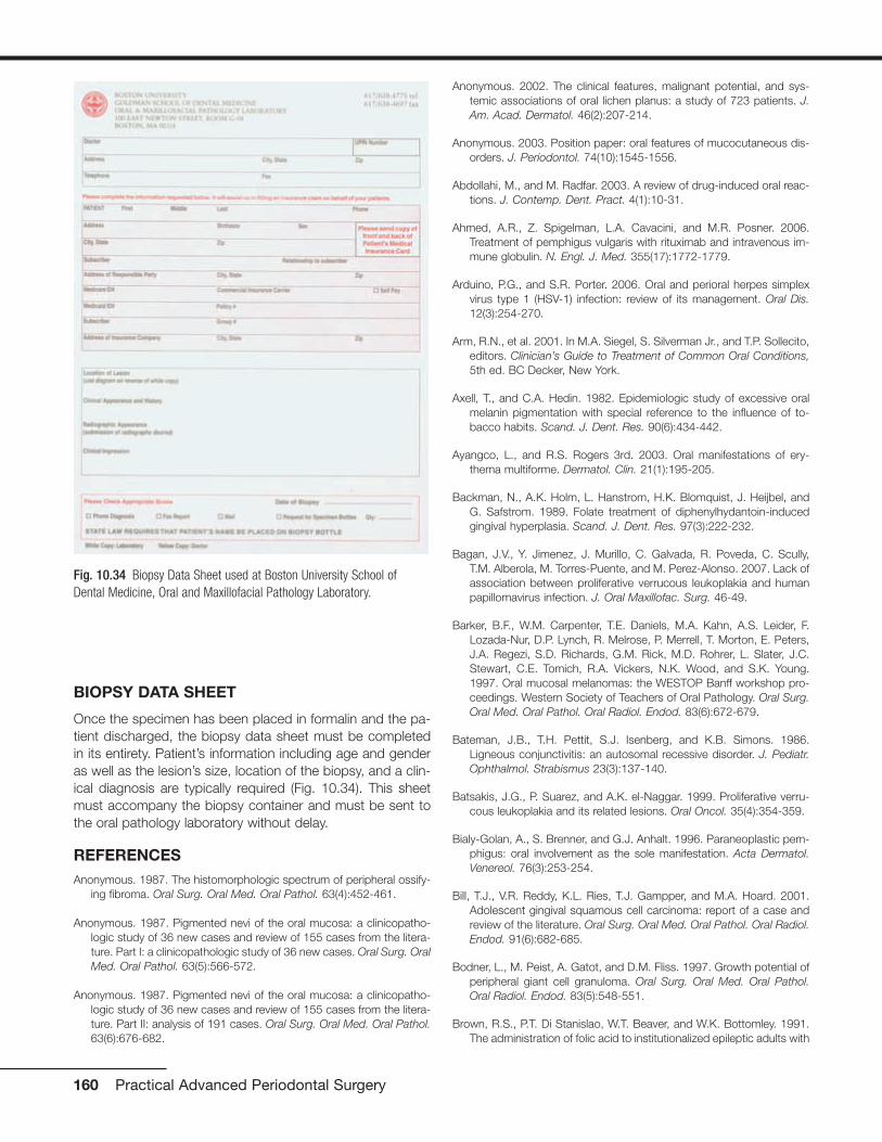
BIOPSY DATA SHEET
Once the specimen has been placed in formalin and the pa-tient discharged, the biopsy data sheet must be completedin its entirety. Patient’s information including age and genderas well as the lesion’s size, location of the biopsy, and a clin-ical diagnosis are typically required (Fig. 10.34). This sheetmust accompany the biopsy container and must be sent tothe oral pathology laboratory without delay.
REFERENCESAnonymous. 1987. The histomorphologic spectrum of peripheral ossify-
ing fibroma. Oral Surg. Oral Med. Oral Pathol. 63(4):452-461.
Anonymous. 1987. Pigmented nevi of the oral mucosa: a clinicopatho-logic study of 36 new cases and review of 155 cases from the litera-ture. Part I: a clinicopathologic study of 36 new cases. Oral Surg. OralMed. Oral Pathol. 63(5):566-572.
Anonymous. 1987. Pigmented nevi of the oral mucosa: a clinicopatho-logic study of 36 new cases and review of 155 cases from the litera-ture. Part II: analysis of 191 cases. Oral Surg. Oral Med. Oral Pathol.63(6):676-682.
Anonymous. 2002. The clinical features, malignant potential, and sys-temic associations of oral lichen planus: a study of 723 patients. J.Am. Acad. Dermatol. 46(2):207-214.
Anonymous. 2003. Position paper: oral features of mucocutaneous dis-orders. J. Periodontol. 74(10):1545-1556.
Abdollahi, M., and M. Radfar. 2003. A review of drug-induced oral reac-tions. J. Contemp. Dent. Pract. 4(1):10-31.
Ahmed, A.R., Z. Spigelman, L.A. Cavacini, and M.R. Posner. 2006.Treatment of pemphigus vulgaris with rituximab and intravenous im-mune globulin. N. Engl. J. Med. 355(17):1772-1779.
Arduino, P.G., and S.R. Porter. 2006. Oral and perioral herpes simplexvirus type 1 (HSV-1) infection: review of its management. Oral Dis.12(3):254-270.
Arm, R.N., et al. 2001. In M.A. Siegel, S. Silverman Jr., and T.P. Sollecito,editors. Clinician’s Guide to Treatment of Common Oral Conditions,5th ed. BC Decker, New York.
Axell, T., and C.A. Hedin. 1982. Epidemiologic study of excessive oralmelanin pigmentation with special reference to the influence of to-bacco habits. Scand. J. Dent. Res. 90(6):434-442.
Ayangco, L., and R.S. Rogers 3rd. 2003. Oral manifestations of ery-thema multiforme. Dermatol. Clin. 21(1):195-205.
Backman, N., A.K. Holm, L. Hanstrom, H.K. Blomquist, J. Heijbel, andG. Safstrom. 1989. Folate treatment of diphenylhydantoin-inducedgingival hyperplasia. Scand. J. Dent. Res. 97(3):222-232.
Bagan, J.V., Y. Jimenez, J. Murillo, C. Galvada, R. Poveda, C. Scully,T.M. Alberola, M. Torres-Puente, and M. Perez-Alonso. 2007. Lack ofassociation between proliferative verrucous leukoplakia and humanpapillomavirus infection. J. Oral Maxillofac. Surg. 46-49.
Barker, B.F., W.M. Carpenter, T.E. Daniels, M.A. Kahn, A.S. Leider, F.Lozada-Nur, D.P. Lynch, R. Melrose, P. Merrell, T. Morton, E. Peters,J.A. Regezi, S.D. Richards, G.M. Rick, M.D. Rohrer, L. Slater, J.C.Stewart, C.E. Tomich, R.A. Vickers, N.K. Wood, and S.K. Young.1997. Oral mucosal melanomas: the WESTOP Banff workshop pro-ceedings. Western Society of Teachers of Oral Pathology. Oral Surg.Oral Med. Oral Pathol. Oral Radiol. Endod. 83(6):672-679.
Bateman, J.B., T.H. Pettit, S.J. Isenberg, and K.B. Simons. 1986.Ligneous conjunctivitis: an autosomal recessive disorder. J. Pediatr.Ophthalmol. Strabismus 23(3):137-140.
Batsakis, J.G., P. Suarez, and A.K. el-Naggar. 1999. Proliferative verru-cous leukoplakia and its related lesions. Oral Oncol. 35(4):354-359.
Bialy-Golan, A., S. Brenner, and G.J. Anhalt. 1996. Paraneoplastic pem-phigus: oral involvement as the sole manifestation. Acta Dermatol.Venereol. 76(3):253-254.
Bill, T.J., V.R. Reddy, K.L. Ries, T.J. Gampper, and M.A. Hoard. 2001.Adolescent gingival squamous cell carcinoma: report of a case andreview of the literature. Oral Surg. Oral Med. Oral Pathol. Oral Radiol.Endod. 91(6):682-685.
Bodner, L., M. Peist, A. Gatot, and D.M. Fliss. 1997. Growth potential ofperipheral giant cell granuloma. Oral Surg. Oral Med. Oral Pathol.Oral Radiol. Endod. 83(5):548-551.
Brown, R.S., P.T. Di Stanislao, W.T. Beaver, and W.K. Bottomley. 1991.The administration of folic acid to institutionalized epileptic adults with
160 Practical Advanced Periodontal Surgery
Fig. 10.34 Biopsy Data Sheet used at Boston University School ofDental Medicine, Oral and Maxillofacial Pathology Laboratory.

phenytoin-induced gingival hyperplasia. A double-blind, randomized,placebo-controlled, parallel study. Oral Surg. Oral Med. Oral Pathol.71(5):565-568.
Buchner, A., and L.S. Hansen. 1979. The histomorphologic spectrum ofthe gingival cyst in the adult. Oral Surg. Oral Med. Oral Pathol.48(6):532-539.
Buchner, A., P.W. Merrell, and W.M. Carpenter. 2004. Relative frequencyof solitary melanocytic lesions of the oral mucosa. J. Oral Pathol.Med. 33(9):550-557.
Buduneli, E., N. Buduneli, and T. Unal. 2001. Long-term follow-up of pe-ripheral ossifying fibroma: report of three cases. Periodontal. Clin.Investig. 23(1):11-14.
Campisi, G., O. Di Fede, and C. Di Liberto. 2003. [Incisional biopsy inoral medicine: punch vs traditional procedure]. Minerva Stomatol.52(11-12):481-488.
Carrera Grano, I., L. Berini Aytes, and C.G. Escoda. 2001. Peripheral os-sifying fibroma. Report of a case and review of the literature. Med.Oral 6(2):135-141.
Cheng, Y.S., T.D. Rees, J.M. Wright, and J.M. Plemons. 2001.Childhood oral pemphigoid: a case report and review of the literature.J. Oral Pathol. Med. 30(6):372-377.
Coletta, R.D., and E. Graner. 2006. Hereditary gingival fibromatosis: asystematic review. J Periodontol. 77(5):753-764.
Cuisia, Z.E., and R.B. Brannon. 2001. Peripheral ossifying fibroma—a clin-ical evaluation of 134 pediatric cases. Pediatr. Dent. 23(3):245-248.
Daley, T.D., and G.P. Wysocki. 1990. Foreign body gingivitis: an iatro-genic disease? Oral Surg. Oral Med. Oral Pathol. 69(6):708-712.
Damm, D.D., A. Curran, D.K. White, and J.F. Drummond. 1999.Leukoplakia of the maxillary vestibule—an association with Viadent?Oral Surg. Oral Med. Oral Pathol. Oral Radiol. Endod. 87(1):61-66.
Dibart, S., and M. Karima. 2006. Practical Periodontal Plastic Surgery.Blackwell Publishing, Ames, IA.
Drew, H.J., R.I. Vogel, W. Molofsky, H. Baker, and O. Frank. 1987. Effectof folate on phenytoin hyperplasia. J. Clin. Periodontol. 14(6):350-356.
D’Silva, N.J., D.J. Summerlin, K.G. Cordell, R.A. Abdelsayed, C.E.Tomich, C.T. Hanks, D. Fear, and S. Meyrowitz. 2006. Metastatic tu-mors in the jaws: a retrospective study of 114 cases. J. Am. Dent.Assoc. 137(12):1667-1672.
Eisen, D. 2000. Disorders of pigmentation in the oral cavity. Clin.Dermatol. 18(5):579-587.
Eisen, D., and J.J. Voorhees. 1991. Oral melanoma and other pigmentedlesions of the oral cavity. J. Am. Acad. Dermatol. 24(4):527-537.
Elkhoury, J., D.A. Cacchillo, D.N. Tatakis, J.R. Kalmar, C.M. Allen, andP.P. Sedghizadeh. 2004. Undifferentiated malignant neoplasm in-volving the interdental gingiva: a case report. J. Periodontol. 75(9):1295-1299.
Ellis, E. 2003. Principles of differential diagnosis and biopsy. In L.J.Peterson, E. Ellis III, J.R. Hupp, and M.R. Tucker, editors. Contem-porary Oral and Maxillofacial Surgery, 4th ed. Elsevier, Philadelphia,pp. 458-478.
Eversole, L.R., G.M. Eversole, and J. Kopcik. 2000. Sanguinaria-associated oral leukoplakia: comparison with other benign and dys-plastic leukoplakic lesions. Oral Surg. Oral Med. Oral Pathol. OralRadiol. Endod. 89(4):455-464.
Fatahzadeh, M., and D.A. Sirois. 2002. Multiple intraoral melanoacan-thomas: a case report with unusual findings. Oral Surg. Oral Med.Oral Pathol. Oral Radiol. Endod. 94(1):54-56.
Ferlito, A., and G. Recher. 1980. Ackerman’s tumor (verrucous carci-noma) of the larynx: a clinicopathologic study of 77 cases. Cancer46(7):1617-1630.
Fettig, A., M.A. Pogrel, S. Silverman, Jr., T.E. Bramanti, M. Da Costa, andJ.A. Regezi. 2000. Proliferative verrucous leukoplakia of the gingiva.Oral Surg. Oral Med. Oral Pathol. Oral Radiol. Endod. 90(6):723-730.
Flaitz, C.M. 2000. Oral melanoacanthoma of the attached gingiva. Am.J. Dent. 13(3):162.
Gallagher, G., S. Kabani, and V. Noonan. 2005. Desquamative gingivitis.J. Mass. Dent. Soc. 54(3):38.
Garcia, F.V.M.J., M. Pascual-Lopez, M. Elices, E. Dauden, A. Garcia-Diez, and J. Fraga. 2002. Superficial mucoceles and lichenoid graftversus host disease: report of three cases. Acta Derm. Venereol.82(6):453-455.
Giunta, J.L. 2002. Gingival cysts in the adult. J. Periodontol. 73(7):827-831.
Gokbuget, A.Y., S. Mutlu, C. Scully, A. Efeoglu, S.R. Porter, P. Speight,G. Erseven, and M. Karacorlu. 1997. Amyloidaceous ulcerated gingi-val hyperplasia: a newly described entity related to ligneous conjunc-tivitis. J. Oral. Pathol. Med. 26(2):100-104.
Gordon, S. 2000. Foreign body gingivitis associated with a new crown:EDX analysis and review of the literature. Oper. Dent. 25(4):344-348.
Gordon, S.C., and T.D. Daley. 1997. Foreign body gingivitis: identificationof the foreign material by energy-dispersive x-ray microanalysis. OralSurg. Oral Med. Oral Pathol. Oral Radiol. Endod. 83(5):571-576.
Gravitis, K., T.D. Daley, and M.A. Lochhead. 2005. Management of pa-tients with foreign body gingivitis: report of 2 cases with histologicfindings. J. Can. Dent. Assoc. 71(2):105-109.
Gunhan, O., M. Gunhan, E. Berker, C.A. Gurgan, and H. Yildirim. 1999.Destructive membranous periodontal disease (Ligneous periodonti-tis). J. Periodontol. 70(8):919-925.
Hansen, L.S., J.A. Olson, and S. Silverman Jr. 1985. Proliferative verru-cous leukoplakia. A long-term study of thirty patients. Oral Surg. OralMed. Oral Pathol. 60(3):285-298.
Hedin, C.A. 1977. Smoker’s melanosis. Arch. Dermatol. 113:1533-1538.
Hedin, C.A., J.J. Pindborg, and T. Axell. 1993. Disappearance ofsmoker’s melanosis after reducing smoking. J Oral Pathol Med22(5):228-230.
Heinemann, C., T. Fischer, U. Barta, A. Michaelides, and P. Elsner. 2006.Plasma cell mucositis with oral and genital involvement—successfultreatment with topical cyclosporin. J. Eur. Acad. Dermatol. Venereol.20(6):739-740.
Hirshberg, A., and A. Buchner. 1995. Metastatic tumours to the oral re-gion. An overview. Eur. J. Cancer B Oral Oncol. 31B(6):355-360.
Periodontal Medicine and Biopsy Techniques 161
Huff, J.C., W.L. Weston, and M.G. Tonnesen. 1983. Erythema multi-forme: a critical review of characteristics, diagnostic criteria, andcauses. J. Am. Acad. Dermatol. 8(6):763-775.
Kahn, M.A., D.R. Weathers, and J.G. Hoffman. 2005. Transformation ofa benign oral pigmentation to primary oral melanoma. Oral Surg. OralMed. Oral Pathol. Oral Radiol. Endod. 100(4):454-459.
Kataoka, M., J. Kido, Y. Shinohara, and T. Nagata. 2005. Drug-inducedgingival overgrowth—a review. Biol. Pharm. Bull. 28(10):1817-1821.
Kaur, C., G.P. Thami, R. Sarkar, and A.J. Kanwar. 2001. Plasma cell mu-cositis. J. Eur. Acad. Dermatol. Venereol. 15(6):566-567.
Kauzman, A., M. Pavone, N. Blanas, and G. Bradley. 2004. Pigmentedlesions of the oral cavity: review, differential diagnosis, and case pre-sentations. J. Can. Dent. Assoc. 70(10):682-683.
Kemp, S., G. Gallagher, and S. Kabani. 2005. Case report: Oral involve-ment as an early manifestation of Wegener’s granulomatosis. OralSurg. Oral Med. Oral Pathol. 100(2):187.
Koch, B.B., D.K. Trask, H.T. Hoffman, L.H. Karnell, R.A. Robinson, W.Zhen, and H.R. Menck. 2001. National survey of head and neck ver-rucous carcinoma: patterns of presentation, care, and outcome.Cancer 92(1):110-120.
Laskaris, G., A. Triantafyllou, and P. Economopoulou. 1988. Gingivalmanifestations of childhood cicatricial pemphigoid. Oral Surg. OralMed. Oral Pathol. 66(3):349-352.
Macleod, R.I., and J.E. Ellis. 1989. Plasma cell gingivitis related to theuse of herbal toothpaste. Br. Dent. J. 166(10):375-376.
Magnusson, B.C., and L.G. Rasmusson. 1995. The giant cell fibroma. Areview of 103 cases with immunohistochemical findings. ActaOdontol. Scand. 53(5):293-296.
Manchanda, Y., T. Tejasvi, R. Handa, and M. Ramam. 2003. Strawberrygingiva: a distinctive sign in Wegener’s granulomatosis. J. Am. Acad.Dermatol. 49(2):335-337.
Martin-Granizo, R., F. Rodriguez-Campo, L. Naval, and F.J. DiazGonzalez. 1997. Squamous cell carcinoma of the oral cavity inpatients younger than 40 years. Otolaryngol Head Neck Surg. 117(3 Pt 1):268-275.
Mavrogiannis, M., J.S. Ellis, R.A. Seymour, and J.M. Thomason. 2006.The efficacy of three different surgical techniques in the managementof drug-induced gingival overgrowth. J. Clin. Periodontol. 33(9):677-682.
McCoy, J.M., and C.A. Waldron. 1981. Verrucous carcinoma of the oralcavity. A review of forty-nine cases. Oral Surg. Oral Med. Oral Pathol.52(6):623-629.
McCulloch, C.A. 2004. Drug-induced fibrosis: interference with the intra-cellular collagen degradation pathway. Curr. Opin. Drug Disc. Dev.7(5):720-724.
Mealey, B.L. 2006. Periodontal disease and diabetes: a two-way street.J. Am. Dent. Assoc. 137(Suppl 2):26S-31S.
Medina, J.E., W. Dichtel, and M.A. Luna. 1984. Verrucous-squamouscarcinomas of the oral cavity. A clinicopathologic study of 104 cases.Arch. Otolaryngol. 110(7):437-440.
Mignogna, M.D., L. Lo Muzio, and E. Bucci. 2001. Clinical features ofgingival pemphigus vulgaris. J. Clin. Periodontol. 28(5):489-493.
Mignogna, M.D., L. Lo Russo, and S. Fedele. 2005. Gingival involvementof oral lichen planus in a series of 700 patients. J. Clin. Periodontol.32(10):1029-1033.
Mirowski, G.W., and J.S. Waibel. 2002. Pigmented lesions of the oralcavity. Dermatol. Therapy 15(3):218-228.
Musa, N.J., V. Kumar, L. Humphreys, A. Aguirre, and M.E. Neiders.2002. Oral pemphigoid masquerading as necrotizing ulcerative gin-givitis in a child. J. Periodontol. 73(6):657-663.
Natali, C., J.L. Curtis, L. Suarez, and E.J. Millman. 1991. Oral mucosapigment changes in heavy drinkers and smokers. J. Natl. Med.Assoc. 83(5):434-438.
Naudi, K.B., K.D. Hunter, D.G. MacDonald, and D.H. Felix. 2006.Ligneous alveolar gingivitis in the absence of plasminogen deficiency.J. Oral. Pathol. Med. 35(10):636-638.
Navazesh, M. 1995. Tartar-control toothpaste as a possible contributoryfactor in the onset of superficial mucocele: a case report. Spec. CareDentist 15(2):74-78.
Noonan, V., S. Kabani, and G. Gallagher. 2005. Recurrent intraoral her-pes infection. J Mass Dent Soc 53(4):55.
Nxumalo, T.N., and M. Shear. 1992. Gingival cyst in adults. J. OralPathol. Med. 21(7):309-313.
Odessey, E.A., A.B. Cohn, F. Casper, and L.S. Schechter. 2006.Hereditary gingival fibromatosis: aggressive 2-stage surgical resec-tion in lieu of traditional therapy. Ann. Plast. Surg. 57(5):557-560.
Palefsky, J.M., S. Silverman, Jr., M. Abdel-Salaam, T.E. Daniels, and J.S.Greenspan. 1995. Association between proliferative verrucous leuko-plakia and infection with human papillomavirus type 16. J. OralPathol. Med. 24(5):193-197.
Patten, S.F., and K.J. Tomecki. 1993. Wegener’s granulomatosis: cuta-neous and/oral mucosal disease. J. Am. Acad. Dermatol. 28(5 Pt 1):710-718.
Patton, L.L., J.S. Brahim, and A.R. Baker. 1994. Metastatic malignantmelanoma of the oral cavity. A retrospective study. Oral Surg. OralMed. Oral Pathol. 78(1):51-56.
Prasad, V.N., H.S. Chawla, A. Goyal, K. Gauba, and P. Singhi. 2004.Folic acid and phenytoin induced gingival overgrowth—is there a pre-ventive effect. J. Indian Soc. Pedod. Prev. Dent. 22(2):82-91.
Ramer, M., and R.P. Burakoff. 1997. Smoker’s melanosis. Report of acase. N. Y. State Dent. J. 63(8):20-21.
Ramon Ramirez, J., J. Seoane, J. Montero, G.C. Esparza Gomez, andR. Cerero. 2003. Isolated gingival metastasis from hepatocellular car-cinoma mimicking a pyogenic granuloma. J. Clin. Periodontol.30(10):926-929.
Reznik, D.A. 2005. Oral manifestations of HIV disease. Top. HIV Med.13(5):143-148.
Sanderson, R.J., and J.A. Ironside. 2002. Squamous cell carcinomas ofthe head and neck. BMJ 325(7368):822-827.
162 Practical Advanced Periodontal Surgery

Schott, D., C.E. Dempfle, P. Beck, A. Liermann, A. Mohr-Pennert, M.Goldner, P. Mehlem, H. Azuma, V. Schuster, A.M. Mingers, H.P.Schwarz, and M.D. Kramer. 1998. Therapy with a purified plasmino-gen concentrate in an infant with ligneous conjunctivitis and homozy-gous plasminogen deficiency. N. Engl. J. Med. 339(23):1679-1686.
Scully, C., A.Y. Gokbuget, C. Allen, J.V. Bagan, A. Efeoglu, G. Erseven,C. Flaitz, S. Cintan, T. Hodgson, S.R. Porter, and P. Speight. 2001.Oral lesions indicative of plasminogen deficiency (hypoplasminogen-emia). Oral Surg. Oral Med. Oral Pathol. Oral Radiol. Endod.91(3):334-337.
Scully, C., and S. Porter. 2000. ABC of oral health. Oral cancer. BMJ321(7253):97-100.
Seoane, J., P.I. Varela-Centelles, T.F. Walsh, J.L. Lopez-Cedrun, and I.Vazquez. 2006. Gingival squamous cell carcinoma: diagnostic delayor rapid invasion? J. Periodontol. 77(7):1229-1233.
Serio, F.G., M.A. Siegel, and B.E. Slade. 1991. Plasma cell gingivitis ofunusual origin. A case report. J. Periodontol. 62(6):390-393.
Setterfield, J., P.J. Shirlaw, M. Kerr-Muir, S. Neill, B.S. Bhogal, P. Morgan,K. Tilling, S.J. Challacombe, and M.M. Black. 1998. Mucous mem-brane pemphigoid: a dual circulating antibody response with IgG andIgA signifies a more severe and persistent disease. Br. J. Dermatol.138(4):602-610.
Shade, N.L., W.M. Carpenter, and D.D. Delzer. 1987. Gingival cyst of theadult. Case report of a bilateral presentation. J. Periodontol.58(11):796-799.
Siegel, M.A., and G.J. Anhalt. 1993. Direct immunofluorescence of de-tached gingival epithelium for diagnosis of cicatricial pemphigoid.Report of five cases. Oral Surg. Oral Med. Oral Pathol. 75(3):296-302.
Silverman, S., Jr., and M. Gorsky. 1997. Proliferative verrucous leuko-plakia: a follow-up study of 54 cases. Oral Surg. Oral Med. OralPathol. Oral Radiol. Endod. 84(2):154-157.
Sinha, A., J. Chander, and S. Natarajan. 2006. Erythema multiforme pre-senting as chronic oral ulceration due to unrecognised herpes sim-plex virus infection. Clin. Exp. Dermatol. 31(5):737-738.
Sklavounou, A., and G. Laskaris. 1990. Childhood cicatricial pemphigoidwith exclusive gingival involvement. Int. J. Oral Maxillofac. Surg.19(4):197-199.
Solomon, L.W., A. Aguirre, M. Neiders, A. Costales-Spindler, G.J.Jividen, Jr., M.G. Zwick, and V. Kumar. 2003. Chronic ulcerativestomatitis: clinical, histopathologic, and immunopathologic findings.Oral Surg. Oral Med. Oral Pathol. Oral Radiol. Endod. 96(6):718-726.
Souza, L.B., E.S. Andrade, M.C. Miguel, R.A. Freitas, and L.P. Pinto.2004. Origin of stellate giant cells in oral fibrous lesions determinedby immunohistochemical expression of vimentin, HHF-35, CD68 andfactor XIIIa. Pathology 36(4):316-320.
Spiro, R.H. 1998. Verrucous carcinoma, then and now. Am J Surg176(5):393-397.
Spruance, S.L., N. Bodsworth, H. Resnick, M. Conant, C. Oeuvray, J.Gao, and K. Hamed. 2006. Single-dose, patient-initiated famciclovir:
a randomized, double-blind, placebo-controlled trial for episodictreatment of herpes labialis. J. Am. Acad. Dermatol. 55(1):47-53.
Tal, H., D. Oegiesser, and M. Tal. 2003. Gingival depigmentation by er-bium:YAG laser: clinical observations and patient responses. J.Periodontol. 74(11):1660-1667.
Thornhill, M.H., V. Sankar, X.J. Xu, A.W. Barrett, A.S. High, E.W. Odell,P.M. Speight, and P.M. Farthing. 2006. The role of histopatholo-gical characteristics in distinguishing amalgam-associated orallichenoid reactions and/oral lichen planus. J Oral Pathol Med.35(4):233-240.
Tokgoz, B., H.I. Sari, O. Yildiz, S. Aslan, M. Sipahioglu, T. Okten, O.Oymak, and C. Utas. 2004. Effects of azithromycin on cyclosporine-induced gingival hyperplasia in renal transplant patients. TransplantProc. 36(9):2699-2702.
Treister, N.S., D. Magalnick, and S.B. Woo. 2004. Oral mucosal pigmen-tation secondary to minocycline therapy: report of two cases and areview of the literature. Oral Surg. Oral Med. Oral Pathol. Oral Radiol.Endod. 97(6):718-725.
Umeda, M., and K. Shimada. 1994. Primary malignant melanoma of theoral cavity—its histological classification and treatment. Br. J. OralMaxillofac. Surg. 32(1):39-47.
van der Waal, R.I., J. Buter, and I. van der Waal. 2003. Oral metastases:report of 24 cases. Br. J. Oral Maxillofac Surg. 41(1):3-6.
Velegraki, A., O. Nicolatou, M. Theodoridou, G. Mostrou, and N.J.Legakis. 1999. Paediatric AIDS—related linear gingival erythema: aform of erythematous candidiasis? J. Oral Pathol. Med. 28(4):178-182.
Wakahara, M., T. Kiyohara, M. Kumakiri, T. Ueda, K. Ishiguro, T. Fujita,M. Amagai, and T. Hashimoto. 2005. Paraneoplastic pemphigus withwidespread mucosal involvement. Acta Derm. Venereol. 85(6):530-532.
Walters, J.D., J.K. Will, R.D. Hatfield, D.A. Cacchillo, and D.A. Raabe.2001. Excision and repair of the peripheral ossifying fibroma: a reportof 3 cases. J. Periodontol. 72(7):939-944.
Weckx, L.L., L.B. Hidal, and G. Marcucci. 1990. Oral manifestations ofleukemia. Ear Nose Throat J. 69(5):341-342, 345-346.
Wiernik, P.H., R. De Bellis, P. Muxi, and J.P. Dutcher. 1996. Ex-tramedullary acute promyelocytic leukemia. Cancer 78(12):2510-2514.
Wine, E., A. Ballin, and I. Dalal. 2006. Infantile erythema multiforme fol-lowing hepatitis B vaccine. Acta Paediatr. 95(7):890-891.
Wright, J.M. 1988. Intraoral melanoacanthoma: a reactive melanocytichyperplasia. Case report. J. Periodontol. 59(1):53-55.
Yuan, K., L.Y. Wing, and M.T. Lin. 2002. Pathogenetic roles of angio-genic factors in pyogenic granulomas in pregnancy are modulated byfemale sex hormones. J. Periodontol. 73(7):701-708.
Zakrzewska, J.M. 1999. Fortnightly review: oral cancer. BMJ 318(7190):1051-1054.
Periodontal Medicine and Biopsy Techniques 163
HISTORY
Implant placement in the edentulous maxilla often representsa clinical challenge due to insufficient bone height aftercrestal bone resorption and maxillary sinus pneumatization.Surgical approaches that were developed over the past yearsaim to restore bone height in the posterior maxilla to create asufficient implant bed. Boyne and James (1980) were the firstto describe a procedure that uses existing space in the max-illary sinus by lifting up the Schneiderian membrane from itsbony surface and filling this newly created space with aug-mentation material. Several modifications of the originally de-scribed surgical procedure were developed; however, thebasic principle of increasing maxillary bone height by placinggraft material in the maxillary sinus after detaching theSchneiderian membrane remained the same (Davarpanah etal. 2001, Fugazzotto and De Paoli 2002, Summers 1994).Grafting materials used to augment bone height in the poste-rior maxilla can be categorized into four groups: autogenousbone, allografts (from human), xenografts (from a nonhumanspecies), and alloplasts (synthetic materials). Autogenousbone is the only grafting material with an osteogenic poten-tial, and it has been shown that its use in sinus augmentationcan achieve predictable results. Furthermore, autogenousbone requires shorter healing times (4 months versus 8 to 10months) because it contains living cells and growth factors.Unfortunately, its availability is limited due to anatomical con-fines and donor site morbidity (Block and Kent 1997,Cammack et al. 2005, Froum et al. 1998, Garg 1999, Pikos1996, Wheeler 1997). Several current approaches aim toovercome those boundaries; one novel approach uses con-cepts previously established in the field of tissue engineering.In contrast to conventional one-dimensional in vitro cell cul-ture, tissue-engineering techniques aim to mimic an in vivoenvironment by using scaffolds, which arrange cells in athree-dimensional fashion (Risbud 2001). Living tissues thatotherwise would be limited in their potential to grow can becontained and even expanded in vitro before being reintro-duced in vivo.
Periosteum, a membrane that closely enfolds bone, consistsof connective tissue and contains chondroprogenitor and os-teoprogenitor cell populations (Hutmacher and Sittinger2003). It has been shown that these progenitor cells can beisolated and stimulated in vitro to form cartilage and boneusing tissue-engineering techniques (Arnold et al. 2002,Breitbart et al. 1998). In 2003, Schmelzeisen and colleaguesdescribed a clinical procedure that substitutes autogenousbone graft material with tissue-engineered bone in a sinus
augmentation procedure. Periosteal tissue was harvestedfrom the oral cavity, and its progenitor cells were isolated andexpanded in a three-dimensional bioabsorbable polymerfleece matrix in vitro. The matured transplants were insertedin the maxillary sinus between the elevated Schneiderianmembrane and the bony floor of the sinus. A number offollow-up publications and a prospective clinical study demon-strated successful remodeling of the graft material, thereby es-tablishing sinus augmentation with tissue-engineered bone asa possible option for overcoming current limitations of autoge-nous bone grafting in the posterior maxilla (Schimming andSchmelzeisen 2004, Schmelzeisen et al. 2003).
Implant placement can occur at the same surgical appoint-ment (immediate placement) or following a healing period(delayed placement) depending on the remaining boneheight. It is generally acknowledged that for an immediateplacement, at least 4 to 5 mm of remaining ridge height isnecessary to achieve sufficient immobilization of implantsduring maturation of the sinus graft (Jensen et al. 1998).
INDICATIONS
• Insufficient bone height in the posterior maxilla for dentalimplant placement
• Need for a large amount of autogenous bone graftingmaterial
• Patient’s refusal to have a bone graft from a source that isnot his or her own
CONTRAINDICATIONS
• Presence of uncontrolled diabetes, immune diseases, orother contraindicating systemic conditions
• Thrombocytopenia or allergically induced thrombocytope-nia (type II)
• Radiation therapy to the head and neck area 12 monthsbefore proposed surgical treatment
• Chemotherapy in the 12 months before proposed surgicaltreatment
• Active sinus infection or a history of persistent sinus in-fections
• Hypersensitivity to bovine albumin, penicillin, gentamicin,amphotericin B
• Excessive smoking habit
165
Chapter 11 Sinus Augmentation Using Tissue-Engineered Bone
Ulrike Schulze-Späte, DMD, PhD, and Luigi Montesani, MD, DDS

• Alcohol and drug abuse
• Physical and psychological handicaps
• Pregnancy and lactating patients
ARMAMENTARIUM
1. For the harvesting procedure, a basic surgical kit such asthe one described in Practical Periodontal Plastic Surgery(Dibart and Karima) and an osseous coagulum collector(Citagenix Inc., Laval, Quebec, Canada) can be used.
2. For the sinus augmentation procedure, a basic surgical kitand the following can be used:
• Angulated elevation instruments for separation of theSchneiderian membrane from the inner bony surface ofthe maxillary sinus (Hu-Friedy, Chicago, IL, USA)
• CollaTape (Zimmer Dental, Carlsbad, CA, USA)
• Bio-Oss (Osteohealth, Shirley, NY, USA)
• Resorbable membrane (Bio-Guide; Osteohealth; andRCM, Bicon, Boston, MA, USA)
SINUS AUGMENTATION USING TISSUE-ENGINEERED BONE DISCS
Technique
Sinus augmentation using tissue-engineered bone requirestwo surgical procedures: harvesting and transplant implanta-tion surgery.
Harvesting Procedure
Periosteal tissue can be obtained from several locations in theoral cavity. However, access to the lateral cortex of themandibular body in the apical region of the first molar area isrelatively easy and not too invasive. After administering localanesthesia, an intrasulcular or intravestibular incision parallelto the mucogingival junction is made using a No. 15 blade.The incision on the buccal side of the first mandibular molarshould extend at least one and one-half teeth toward theanterior and posterior in order to obtain sufficient access. Apartial thickness flap is elevated to expose the underlyingperiosteum. After outlining the area with a No. 15 blade, theperiosteal biopsy (approximately 1 cm2) can be collected usinga back action chisel or osseous coagulum collector (Fig. 11.1).
Alternatively, an alveolar bone biopsy (8 � 10 � 2 mm) canbe taken from the same side or the tuberosity area after ex-posing the bone using a distal wedge incision. The collectedtissue biopsy needs to be stored in appropriate sterile tissuecontainers and transferred to an in vitro cell/tissue facility forfurther culturing and tissue expansion. In addition, a bloodsample (approximately 126 mL of blood will be sufficient for10 tissue-engineered discs) needs to be taken from the pa-tient. This blood sample will be used to produce serum,
which is essential for future culturing of the isolated periostealcells (Schimming and Schmelzeisen 2004). The donor sidecan be sutured with either resorbable (5-0 chromic gut) ornonresorbable (5-0 silk) suture material.
Postoperative Management
Pain medications should be prescribed as needed. In addition,chlorhexidine rinses twice a day for 21 days starting 1 day afterthe surgery should be included in the postoperative regimen.
Treatment and Expansion of PeriostealBiopsies
The periosteal tissue biopsy can be cultured using a tissueengineering protocol described by Schmelzeisen and col-leagues (2003). In addition, commercial companies such asBio Tissue Technology, Freiburg, Germany, offer to overtakelaborious cell culturing and provide the clinician with the fin-ished tissue-engineered bone discs.
The periosteum needs to be enzymatically digested to isolateprogenitor cells. Collagenase CLSII (Clostridium histolyticum)at a concentration of 333 U/mL (Biochrom, Cambridge, UK)in 1:1 DMEM/Ham’s F-12 (Dulbecco’s modified Eagle’smedium; Invitrogen, Carlsbad, CA, USA) can be used, andthe resulting cell suspension needs to be washed with phos-phate-buffered saline (PBS; Invitrogen). Cells are countedusing a hemocytometer and stained with Trypan blue dye todetermine the overall cell viability. Afterward, they are resus-pended in 1:1 DMEM/Ham’s F-12 supplemented with 10%autologous serum and seeded into cell culture flasks. The
166 Practical Advanced Periodontal Surgery
Fig. 11.1. Collection of a periosteal biopsy. Periosteal tissue was har-vested from the goniac angle of the mandible.

flasks are cultured in a cell culture incubator adjusted to37°C, 3.5% CO2, and 95% humidity. The medium needs tobe replaced every 2 days until cells reach a 70% confluency.At this point, cells are trypsinized (0.02% trypsin and 0.02%EDTA in PBS) for 5 minutes and seeded at a density of5000/mm2. This step needs to be repeated four times to in-crease cell number. Following trypsinization, cells are nowready to be incorporated into the transplant discs (Perka etal. 2000). Several scaffold materials such as synthetic andnatural polymers, composites, and ceramics have beentested in recent years (Sittinger et al. 2004). They need to bebiocompatible and resorbable to facilitate integration of thefuture graft into an in vivo environment. To incorporate cellsinto the scaffold, cells are suspended in 1:1 DMEM/Ham’sand mixed with human fibrinogen (TissueColl; BaxterImmuno, Vienna, Austria) in a 3:1 ratio. The resulting cell so-lution is soaked into polymer fleeces (e.g., Ethicon, Cornelia,GA, USA) and subsequently polymerized by adding bovinethrombin (TissueColl) in a 1:10 PBS dilution. The transplantdiscs are cultured for an additional week in DMEM/Ham’ssupplemented with 5% autologous serum, dexamethasone10�7 Mol, ß-glycerophosphate 10 mM, and ascorbic acid (50mg/L). At this point (approximately 7 weeks after the harvest-ing procedure), the transplants are ready for implantation.Each final disc contains around 1.5 � 106 cells and is circa 2 � 10 mm in size (Fig. 11.2A, B).
TRANSPLANT IMPLANTATION SURGERY(SINUS AUGMENTATION PROCEDURE USINGTISSUE-ENGINEERED BONE DISCS)
Before the sinus augmentation procedure, a computer to-mography scan or panoramic radiograph should be takenfrom the selected area (see Fig. 11.4A later). The procedurecan be performed under local anesthesia. A midcrestal inci-sion is made with mesial and distal releasing incisions ex-tending well into the buccal fold. The mucoperiosteal flap isreflected in a full-thickness manner, and care needs to betaken to completely release the tissue for a tension-free ac-cess to the lateral wall of the maxillary sinus.
There are three classic approaches to enter the maxillarysinus. In the Caldwell-Luc approach, the window is anteriorto the zygomatic buttress; in a low position, the window is sit-uated next to the alveolar crest; and in a mid maxillary posi-tion, the lateral window is situated between alveolar crest andzygomatic buttress (Lazzara 1996, Summers 1994, Zitzmannand Scharer 1998). In the above-introduced application, alateral window approach is recommended. However, in anycase, the osteotomy window should be placed according tothe anatomical structure of the maxillary sinus and its inferiorhorizontal border should be 3 to 4 mm above the sinus floor.The oval window is outlined under continuous sterile saline ir-rigation with a high-speed handpiece and either a carbide or
Sinus Augmentation Using Tissue-Engineered Bone 167
Fig. 11.2. Tissue-engineered bone discs. A, Discs were kept in transportation medium until implantation. B, Scaffolds need to be carefully handled soas to not destroy the incorporated cells.
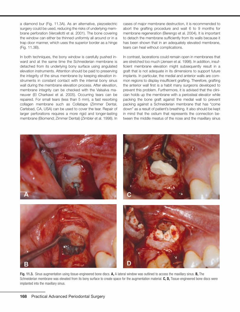
a diamond bur (Fig. 11.3A). As an alternative, piezoelectricsurgery could be used, reducing the risks of underlying mem-brane perforation (Vercellotti et al. 2001). The bone coveringthe window can either be thinned uniformly all around or in atrap door manner, which uses the superior border as a hinge(Fig. 11.3B).
In both techniques, the bony window is carefully pushed in-ward and at the same time the Schneiderian membrane isdetached from its underlying bony surface using angulatedelevation instruments. Attention should be paid to preservingthe integrity of the sinus membrane by keeping elevation in-struments in constant contact with the internal bony sinuswall during the membrane elevation process. After elevation,membrane integrity can be checked with the Valsalva ma-neuver (El Charkawi et al. 2005). Occurring tears can berepaired. For small tears (less than 5 mm), a fast resorbingcollagen membrane such as Collatape (Zimmer Dental,Carlsbad, CA, USA) can be used to cover the tear. Repair oflarger perforations requires a more rigid and longer-lastingmembrane (Biomend; Zimmer Dental) (Zimbler et al. 1998). In
cases of major membrane destruction, it is recommended toabort the grafting procedure and wait 6 to 9 months formembrane regeneration (Berengo et al. 2004). It is importantto detach the membrane sufficiently from its walls because ithas been shown that in an adequately elevated membrane,tears can heal without complications.
In contrast, lacerations could remain open in membranes thatare stretched too much (Jensen et al. 1998). In addition, insuf-ficient membrane elevation might subsequently result in agraft that is not adequate in its dimensions to support futureimplants. In particular, the medial and anterior walls are com-mon regions to display insufficient grafting. Therefore, graftingthe anterior wall first is a habit many surgeons developed toprevent this problem. Furthermore, it is advised that the clini-cian holds up the membrane with a periosteal elevator whilepacking the bone graft against the medial wall to preventpacking against a Schneiderian membrane that has “comedown” as a result of patient’s breathing. It also should be keptin mind that the ostium that represents the connection be-tween the middle meatus of the nose and the maxillary sinus
168 Practical Advanced Periodontal Surgery
Fig. 11.3. Sinus augmentation using tissue-engineered bone discs. A, A lateral window was outlined to access the maxillary sinus. B, TheSchneiderian membrane was elevated from its bony surface to create space for the augmentation material. C, D, Tissue-engineered bone discs wereimplanted into the maxillary sinus.

is approximately 25 mm above the floor of the sinus. Blockadedue to extensive sinus grafting can result in a chronic infectionof the maxillary sinus (Doud Galli et al. 2001).
Assuming that the membrane is elevated sufficiently, thetissue-engineered discs, which can be kept in the transporta-tion medium during the procedure, are then inserted into thesinus and gently packed until the space between the sinusmembrane and bony walls of the sinus is filled (Fig. 11.3C, D).In addition, bone augmentation material such as BioOss(Osteohealth, Shirley, NY, USA) can be used as a protectivelayer on the outside of the graft (Fig. 11.3E). The windowshould be covered with a membrane that overlaps its outlinesand thereby protects the grafted side. Either a nonresorbablemembrane with securing tacks or a resorbable one can beused for this purpose (Fig. 11.3F).
Afterward, the mucoperiosteal flap is positioned back tocover the surgical site. It might be necessary to release theperiosteum of the flap with a No. 15 blade in order to facili-
tate a tension-free closure. The flap can now be sutured witheither resorbable (such as Vicryl; Ethicon, Carnelia, GA, USA)or nonresorbable (such as Gore-Tex suture; Gore Medical,Flagstaff, AZ, USA) suture material in single interrupted su-tures (Fig. 11.3G). Whenever necessary, these sutures can bereplaced by a continuous suture and further secured withhorizontal mattress sutures.
Postoperative Management
• Antibiotic therapy should be started the day before the pro-cedure: 500 mg amoxicillin 3 times daily for 7 days (300mg clindamycin 4 times daily should be prescribed forpenicillin-sensitive patients).
• Analgesics: Acetaminophen plus codeine (Tylenol #3) oribuprofen (Motrin 600 mg) 3 times a day or as necessary isrecommended.
• Anti-inflammatory drugs: Dexamethasone can be pre-scribed for 5 days in the following manner (day of surgery:
Sinus Augmentation Using Tissue-Engineered Bone 169
Fig. 11.3. (continued) E, The discs were covered with BioOss (Osteohealth) augmentation material (optional). F, The grafted area was covered with aresorbable membrane (Bioguide; Osteohealth). G, The flap was sutured in its original position with single interrupted sutures (Gore-Tex; Gore Medical).

3.75 mg; day 2: 3 mg; day 3: 2.25 mg: day 4: 1.5 mg; day5: 0.75 mg). This will control the swelling and alleviate thediscomfort.
• Afrin spray: Patients should be given this spray to use sothey will not blow their nose for 2 weeks, as that will impairproper healing of the graft.
• Antiseptic rinses: Chlorhexidine digluconate rinses twice aday for 21 days starting 1 day after the surgery are recom-mended.
• Patients can wear their complete dentures after the proce-dure; however, the buccal flange needs to be reduced andlater on relined with a soft reliner. Partial dentures shouldbe worn only if they have an acrylic base, which allows ap-
propriate relief and facilitates soft relining. However, it isrecommended to advise the patient that the denture isworn for aesthetic reasons and not for function until theday of suture removal.
Healing
Studies revealed sufficient new bone formation 4 monthsafter implantation of the tissue-engineered bone discs(Schmelzeisen et al. 2003). Therefore, dental implants can beplaced 4 months after the grafting procedure (Fig. 11.4B, C).A core biopsy can be taken during the surgery and subjectedto histologic staining to determine current mineralization sta-tus of the augmented bone (Fig. 11.5). Afterward, implantscan be restored according to standard protocols (Fig. 11.6).
170 Practical Advanced Periodontal Surgery
Fig. 11.4 Radiographic evaluation of the grafted site. A, A periapicalradiograph was taken and revealed inadequate bone height beforeimplant placement. B, Radiograph depicting the augmented site beforeimplant placement. C, Implant was placed successfully in the grafted siteachieving primary stability.

Possible Complications
Complications occurring after sinus augmentation with tissue-engineered bone should not be different from complicationsassociated with other grafting materials, assuming that thediscs were prepared and transported under sterile conditions.
Swelling, Bruising, and Bleeding
Patients might experience swelling and bruising in the surgi-cal areas after the procedures. It is recommended that coldpads be used for the initial 24 hours. Afterward, the applica-tion of warm pads in combination with anti-inflammatorymedications will help to reduce swelling and discomfort. It isnot unusual for patients to report an exacerbated feeling ofpain 5 days after the procedure because at this time point thecorticosteroid regimen has ended. Therefore, patients shouldbe informed beforehand and advised to continue taking thenonsteroidal anti-inflammatory drugs for 1 week.
In the case of nasal bleeding due to laceration of the Schnei-derian membrane, patients should be reassured (as this willhappen after they have left your office) and pressure with acotton ball should be applied to stop the nasal bleeding.
Infraorbital Nerve Paresthesia
Paresthesia of the area innervated by the infraorbital nervecan be caused by blunt retraction over the neurovascularbundle. It usually is transient and disappears within a fewweeks. However, in some cases, long-lasting paresthesia, upto several months, is possible.
Infection of the Grafted Site and MembraneExposure
Infection spreading from an infected graft can lead to pansi-nusitis, can spread to the orbit, dura, and brain, and requiresintervention. An early sign is the occurrence of an intraoralswelling 1 week postsurgery; however, signs of infections canbe detected as early as 3 days. In the case of an infection,prescription of antibiotics such as clindamycin with a loadingdose of 600 mg followed by a dosage of 300 mg 4 times isrecommended. Metronidazole can be added for anaerobiccoverage at 500 mg 3 times daily. Usually, localized infectionswill respond to the treatment. However, in case of persistentsymptomatology, it is imperative to pursue aggressive treat-ment, which includes incision and drainage over the originalincision line. In addition, aerobic and anaerobic culture resultscould be used as a supportive adjunct to determine futuretreatment.
Sometimes local debridement is appropriate and sufficient. Ifthe graft needs to be completely removed, a long-lasting col-lagen membrane should be used to cover the window. Aftera healing period of 3 to 4 months, the site can be reenteredfor an additional grafting procedure. In response to an infec-tion, oroantral fistulas can form that are treatable with antibi-otics and oral chlorhexidine rinses. Nevertheless, large and
Sinus Augmentation Using Tissue-Engineered Bone 171
Fig. 11.5 Histologic staining of core biopsy taken from the futureimplant side. Goldner`s staining shows mineralized bone (green; seewhite arrow) and newly formed osteoid (red; see black arrow).
Fig. 11.6 Clinical view of the restored implant. A, B. Implant wasrestored with a single porcelain-fused metal (PFM) crown.
A
B
persistent fistulas require surgical intervention. In case of apremature exposure of the membrane, it has been shownthat oral bacteria can penetrate the membrane surface within4 weeks (Simion et al. 1994). Thus, it is advised to continuethe use of chlorhexidine mouth rinses until the final implantsurgery. In any case, the patient should be closely followed inorder to intervene if an infection develops and the membraneneeds to be removed.
Taken together, infection should be treated in a comprehen-sive way to minimize the risk of spreading and maximize thesuccess of the grafting procedure.
REFERENCESArnold, U., K. Lindenhayn, and C. Perka. 2002. In vitro-cultivation of
human periosteum derived cells in bioresorbable polymer-TCP-composites. Biomaterials 23:2303–2310.
Berengo, M., S. Sivolella, Z. Majzoub, and G. Cordioli. 2004. Endoscopicevaluation of the bone-added osteotome sinus floor elevation proce-dure. Int. J. Oral Maxillofac. Surg. 33(2):189–194.
Block, M.S., and Kent J.N. 1997. Sinus augmentation for dental im-plants: the use of autogenous bone. J. Oral Maxillofac. Surg.55(11):1281–1286.
Boyne, P.J., and R.A. James. 1980. Grafting of the maxillary sinus floorwith autogenous marrow and bone. J. Oral Surg. 38(8):613–616.
Breitbach, A.S., D.A. Grande, R. Kessler, J.T. Ryabi, R.J. Fitzsimmons,and R.T. Grant. 1998. Tissue engineered bone repair of calvarial de-fects using culture periosteal cells. Plast. Reconstr. Surg.101:567–574.
Cammack, G.V. 2nd., M. Nevins, D.S. Clem 3rd., J.P. Hatch, and J.T.Mellonig. 2005. Histologic evaluation of mineralized and demineral-ized freeze-dried bone allograft for ridge and sinus augmentations.Int. J. Periodont. Restor. Dent. 25(3):231–237.
Davarpanah, M., H. Martinez, J.F. Tecucianu, G. Hage, and R. Lazzara.2001. The modified osteotome technique. Int. J. Periodont. Restor.Dent. 21(6):599–607.
Dibart, S., and M. Karima. 2006. Practical Periodontal Plastic Surgery.Blackwell Publishing, Ames, IA.
Doud Galli, S.K., R.A. Lebowitz, R.J. Giacchi, R. Glickman, and J.B.Jacobs. 2001. Chronic sinusitis complicating sinus lift surgery. Am. J.Rhinol. 15(3):181–186.
El Charkawi, H.G., A.S. El Askary, and A. Ragab. 2005. Endoscopic re-moval of an implant from the maxillary sinus: a case report. ImplantDent. 14(1):30–35.
Froum, S.J., D.P. Tarnow, S.S. Wallace, M.D. Rohrer, and S.C. Cho.1998. Sinus floor elevation using an organic bovine bone matrix(OsteoGraf/N) with and without autogenous bone: a clinical, histo-logic, radiographic, and histomorphometric analysis—part 2 of anongoing prospective study. Int. J. Periodont. Restor. Dent. 18(6):528-543.
Fugazzotto, P.A., and S. De Paoli. 2002. Sinus floor augmentation at the time of maxillary molar extraction: success and failure rates of
137 implants in function for up to 3 years. J. Periodontol. 73(1):39-44.
Garg, A.K. 1999. Augmentation grafting of the maxillary sinus for place-ment of dental implants: anatomy, physiology, and procedures.Implant Dent. 8(1):36-46.
Hutmacher, D.W., and M. Sittinger. 2003. Periosteal cells in bone tissueengineering. Tiss. Eng. 9(Suppl 1):S45-S64.
Jensen, O.T., L.B. Shulman, M.S. Block, and V.J. Iacono. 1998. Reportof the Sinus Consensus Conference of 1996. Int. J. Oral Maxillofac.Implants 13(Suppl):11-45.
Lazzara, R.J. 1996. The sinus elevation procedure in endosseous im-plant therapy. Curr. Opin. Periodontol. 3:178-183.
Perka, C., O. Schultz, R.S. Spitzer, K. Lindenhayn, G.R. Burmester, andM. Sittinger. 2000. Segmental bone repair by tissue-engineeredperiosteal cell transplants with bioresorbable fleece and fibrin scaf-folds in rabbits. Biomaterials 21(11):1145-1153.
Pikos, M.A. 1996. Chin grafts as donor sites for maxillary boneaugmentation—part II. Dental Implantol. Update 7(1):1-4.
Risbud, M. 2001. Tissue engineering: implications in the treatment oforgan and tissue defects. Biogerontology 2:117-125.
Schmelzeisen, R., R. Schimming, and M. Sittinger. 2003. Making bone:implant insertion into tissue-engineered bone for maxillary sinus flooraugmentation—a preliminary report. J. Craniomaxillofac. Surg.31:34-39.
Schimming, R., and R. Schmelzeisen. 2004. Tissue-engineered bone formaxillary sinus augmentation. J. Oral Maxillofac. Surg. 62(6):724-729.
Sittinger, M., D.W. Hutmacher, and M.V. Risbud. 2004. Current strategiesfor cell delivery in cartilage and bone regeneration. Curr. Opin.Biotechnol. 15(5):411-418.
Simion, M., P. Trisi, M. Maglione, and A. Piattelli. 1994. A preliminaryreport on a method for studying the permeability of expandedpolytetrafluoroethylene membrane to bacteria in vitro: a scanningelectron microscopic and histological study. J. Periodontol. 65(8):755-761.
Summers, R.B. 1994. A new concept in maxillary implant surgery: the osteotome technique. Compend. Cont.g Educ. Dent. 15(2):152,154-156.
Vercellotti, T., S. De Paoli, and M. Nevins. 2001. The piezoelectric bonywindow osteotomy and sinus membrane elevation: introduction of anew technique for simplification of the sinus augmentation proce-dure. Int. J. Periodont. Restor. Dent. 21(6):561-567.
Wheeler, S.L. 1997. Sinus augmentation for dental implants: the use ofalloplastic materials. J. Oral Maxillofac. Surg. 55(11):1287-1293.
Zimbler, M.S., R.A. Lebowitz, R. Glickman, L.E. Brecht,and J.B. Jacobs.1998. Antral augmentation, osseointegration, and sinusitis: the oto-laryngologist’s perspective. Am. J. Rhinol. 12(5):311-316.
Zitzmann, N.U., and P. Scharer. 1998. Sinus elevation procedures in theresorbed posterior maxilla. Comparison of the crestal and lateral ap-proaches. Oral Surg. Oral Med. Oral Pathol. Oral Radiol. Endod.85(1):8-17.
172 Practical Advanced Periodontal Surgery

ABO. See American Board ofOrthodontics
Acyclovir, for herpes, 158Afrin spray, for sinus augmentation, 170Alveolar bone, 14-16
decortication of, 27-28, 27fmaxilla and mandible, 15-16terminology for, 14-15
Alveolar distraction surgeryfor gingival fibromatosis, 151for vertical alveolar ridge deficiencies,
117-25advantages of, 117-18armamentarium for, 118caution for, 124, 124fcomplications of, 125history of, 117indications for, 117, 117flimitations of, 117postoperative instructions for, 125preoperative instructions for, 124technique for anterior segment,
118-22, 118f-123ftechnique for posterior segment,
122-24, 123f-124fAlveolar volume, PAOO enhancement
of, 27Amalgam
for apicoectomy, 65tattoo, 153, 153f
Amelogenins, in bone stimulation, 10American Board of Orthodontics (ABO),
OGS with, 26Analgesics, for sinus augmentation, 169Anesthesia, local
for alveolar distraction surgery, 118for apicoectomy, 60for papillary construction, 128, 128f
Angiogenesis, in wound-healing, 20-21Antibiotics, for sinus augmentation, 169Anticoagulant therapy, endodontic
therapy and, 54Anti-inflammatory drugs, for sinus
augmentation, 169-70Antiseptic rinses, for sinus augmenta-
tion, 170Antiviral therapy, for herpes, 158Apicoectomy
complications of, 67indications for, 58-59, 59fintraoral examination for, 59-60local anesthesia for, 60medical history review for, 59
moisture control for, 65osteotomy and curettage for, 62-63,
63foverview of, 58postoperative instructions for, 66-67presurgical preparation for, 60radiographic examination for, 60retrofill for, 65-66retropreparation, 64, 65froot resection, 63-64, 64fsoft tissue flap design, 60-61
full-thickness intrasulcular incision,61, 61f
full-thickness submarginal incision,61-62, 62f
papillary-based incision, 62semilunar incision, 60-61
staining and inspection, 64, 64fsuturing and suture removal, 66
Arthritis, periodontitis and, 10Augmentation grafting, with PAOO,
24-26, 25f-26fAutopolymerizing acrylic resin, for
prosthodontics, 75
BAFF. See B-cell activating factorBALP. See Bone-specific alkaline
phosphataseBasal bone, 14-16
maxilla and mandible, 15-16terminology for, 14-15
B-cell activating factor (BAFF), inperiodontitis, 10
Bicon short implant, 132, 132fBiopsy
for desquamative gingivitis, 147-48for metastatic disease, 157for plasma cell gingivitis, 148for sanguinaria-induced leukoplakia,
155, 155ffor squamous cell carcinoma, 156techniques for, 158-60
armamentarium for, 159data sheet for, 160, 160fexcisional scalpel, 159, 159fincisional scalpel, 159
Bisphosphonates, osteonecrosis and, 8-9, 69
“Black triangle,” papillary constructionfor, 127-30
armamentarium for, 127contraindications for, 127
healing of, 130, 130fhistory of, 127indications for, 127possible complications of, 129postoperative instructions for, 129technique for, 127-28, 127f-129f
Bleeding, with sinus augmentation, 171Bone
alveolar, 14-16maxilla and mandible, 15-16terminology for, 14-15
basal, 14-16maxilla and mandible, 15-16terminology for, 14-15
cortical, description of, 5loss of, with miniscrew implants,
49-50physiology and metabolism of, 5-10
composition of, 5density measuring techniques, 8formation of, 5-8implications for dental treatments
of, 8-10types of, 5
remodeling of, 5-8bone formation markers, 6bone resorption markers, 6importance of, 5-6osteoporosis, 7-8periodontitis and, 6stages of, 6
Bone-specific alkaline phosphatase(BALP), as bone formation marker,6
Bone-stimulating factors, for dentalimplants, 9-10
Bovine bone, for PAOO, 23Branemark implant, history of, 131-32,
131f-132fBruising, with sinus augmentation,
171Buccal concavities, in dental implant,
140Buccal connective tissue, vascular
supply of, 16Buccal mucosa, lichen planus of, 146,
146f
Calcitoninin bone remodeling, 7PTH v., 7
Calcium carbonate, in bone matrix, 5
173
Index
Calcium citrate, in bone matrix, 5Calcium sulfate, for apicoectomy, 65Calcium, vitamin D for absorption of,
6-7Caldwell-Luc approach, for sinus
augmentation, 167-68Canines, recovery of impacted, 28-29
labially impacted, 29-33, 32f-34fpalatally impacted, 35-38, 35f-37f
Cells, of bones, 5Cementum
vascular supply to, 19in wound-healing process, 19
Chemotherapy, sinus augmentation and,165
Chlorohexidine gluconate, for apicoec-tomy, 64, 66
Chondroitin sulfate, in groundsubstance, 5
Cleocin. See Clindamycin phosphateClindamycin phosphate (Cleocin), for
PAOO, 23Coldpac, for prosthodontics, 75Collagen
in bone matrix, 5vitamin C for, 6in wound healing, 21
Compact bone, description of, 14, 14fComputed tomography (CT)
for alveolar distraction surgery, 122for dental implant placement, 133-34,
133f-134ffor osteonecrosis, 9for PAOO, 23-24, 24f-25ffor prosthodontics, 71, 105-7, 106f
Cone beam computed tomography, forbone density, 8
Conjunctivitis, 151Cortical bone
density of, 14-15description of, 5, 14-15, 14fminiscrew implants in, 44-46, 46f, 49vascular supply of, 15, 15f
Corticosteroid therapyfor desquamative gingivitis, 148for EM, 149
Corticotomy, description of, 23Crown-lengthening procedure
microsurgical, for prosthodontics, 77-78, 77f, 101, 101f
surgical, microsurgical crown-lengthening procedure v., 77-78,102, 102f
CT. See Computed tomographyCurettage, for apicoectomy, 62-63, 63fCyst, of gingiva, 144-45, 145f
Decorticationdescription of, 23healing of, 27-28, 27f
for labially impacted canines, 29-33,32f-34f
for palatally impacted canines, 35-38,35f-37f
Demineralized freeze-dried bone(DFDBA), for PAOO, 23
Density, description of, 14-15, 14f-15fDental implants, 9-10. See also
Miniscrew implantsbone-stimulating factors, 9-10osseointegration, 9papillary construction after, 127-30
armamentarium for, 127contraindications for, 127healing of, 130, 130fhistory of, 127indications for, 127possible complications of, 129postoperative instructions for, 129technique for, 127-28, 127f-129f
placement of, 131-42entry incision for, 134-35, 135ffixture installation for, 138, 138fhistory of, 131-33, 131f-133fimplants for, 131-32, 132findications for, 133problems and complications of,
138-41, 139f-142fsite preparation for, 135-37,
136f-137ftechnique for, 134, 134f
short, problems with, 141, 141f-142fsinus augmentation for, 165-72
Dental treatments, 8-10dental implants, 9-10mandibular osteoporosis, 10osteonecrosis of jaw, 8-9periodontitis, 10
Desquamative gingivitis, 146diagnosis and treatment of, 147-48pemphigus vulgaris with, 147
DEXA. See Dual Energy X-rayAbsorptiometry
DFDBA. See Demineralized freeze-driedbone
Diabetesendodontic therapy and, 54hyperplastic gingivitis and, 150, 150fsinus augmentation and, 165
Diagnostic casts, for prosthodontics, 70Diagnostic phase, for prosthodontics,
69-70patient I, 72-73, 72f-73fpatient II, 82-84, 84f-85fpatient III, 94-97, 96f-97f
Diagnostic waxing, for prosthodontics,70
Distractorin alveolar distraction surgery, 119-20,
119f-120f, 123-24, 124fgingiva and, 120, 121f
Drillingfor dental implants, 136-37, 136ffor miniscrew implants, 48problems with, 138, 139fwarning for, 136
Dual Energy X-ray Absorptiometry(DEXA), for bone density, 8
Elevatorsfor alveolar distraction surgery, 118,
118ffor tooth replantation, 57
EM. See Erythema multiformeEMD. See Enamel matrix derivativeEnamel matrix derivative (EMD), in bone
stimulation, 10Endochondral ossification, of bone, 5Endodontic therapy
contraindications for, 54-55anatomical challenges, 54-55, 55fcompromised periodontum, 54inadequate root length, 55, 55fmedical history, 54skill, knowledge, and proper
instruments, 54, 55fhistory and evolution of, 51indications for, 52-54
anatomical challenges, 52exploratory surgery, 53-54, 54fiatrogenic factors, 52, 52f-53frelentless inflammation, 53, 53f
periodontic contribution to, 51-67periradicular surgery for, 58-67
complications of, 67indications for, 58-59, 59fintraoral examination for, 59-60local anesthesia for, 60medical history review for, 59moisture control for, 65osteotomy and curettage for,
62-63, 63foverview of, 58postoperative instructions for,
66-67presurgical preparation for, 60radiographic examination for, 60retrofill for, 65-66retropreparation, 64, 65froot resection, 63-64, 64fsoft tissue flap design, 60-61staining and inspection, 64, 64fsuturing and suture removal, 66
rationale for, 52tooth conservation v. implants,
51-52treatment of failed root canal therapy,
52types of, 56-58
incision and drainage, 56, 56fintentional replantation, 56-58
174 Index

root amputation and hemisection,56
Endosteum, description of, 14Epinephrine
for apicoectomy, 65for biopsy, 159
Epithelialization, in wound-healing, 20Epithelial layer, vascular supply to,
19-20, 19f-20fEpulis fissuratum, 149-50, 149fErythema multiforme (EM), 149, 149fExcisional scalpel biopsy, technique for,
159, 159f
Fibroblasts, in wound healing, 20-21Fibroma
diagnosis and treatment of, 144overview of, 143-44, 143fperipheral ossifying, 144, 144f
Fibronectin, in wound healing, 21Fibroplasia, in wound-healing, 20-21Foreign body gingivitis, lichen planus
and, 146, 146fFractal analysis of bone texture, for
bone density, 8Full-thickness intrasulcular incision, in
apicoectomy, 61, 61fFull-thickness submarginal incision, in
apicoectomy, 61-62, 62f
Giant cell fibroma, 143Gingiva
connective tissues of, 16-17, 17f, 19,19f
cyst of, 144-45, 145fdiscrepancy in, 98, 99fdistractor and, 120, 121fenlargement of, 149
leukemia and, 151ligneous gingivitis and, 151
excess, 38-40overview of, 38-39, 38f-39fremoval of, 38-40, 39f-41f
fibroma of, 143-44, 143fminiscrew placement in, 49nodules of, 143overgrowth of, medication-induced,
150, 150fperipheral giant cell granuloma of,
144, 145fpyogenic granuloma of, 144, 144fvascular supply of, 17-18, 17f
Gingival fibromadiagnosis and treatment of, 144overview of, 143-44, 143f
Gingival fibromatosis, 151Gingivectomy
description of, 38-39for gingival fibromatosis, 151
for gingival overgrowth, 150for impacted canines, 29
Gingivitisdesquamative, 146hyperplastic, 150, 150fligneous, 151plasma cell, 148, 148f
Gingivoplastydescription of, 38-39purpose of, 39-40
Gingivostomatitis, herpes with, 157Glycosaminoglycans, in ground
substance, 5Gore-Tex suture material, for PAOO, 23Graft-versus-host disease, mucocele of,
145, 145fGranuloma
diagnosis and treatment of, 144, 145fperipheral giant cell, 144, 145fpyogenic, 144, 144f
Ground substance, in bone matrix, 5Guide, for miniscrew placement, 47,
47f-48f
Hanks balanced salt solution (HBSS), for intentional replantation, 56-57,57f
Haversian system, of bones, 5HBSS. See Hanks balanced salt
solutionHerpes, 157-58, 158fHIV-associated gingivitis, 158Hyaluronic acid, in ground substance, 5Hydroxyapatite, in bone matrix, 5Hyperparathyroidism, bone resorption
and, 7Hyperplastic gingivitis, 150, 150f
Iatrogenic factors, as indication forendodontic therapy, 52, 52f-53f
Implant. See specific implantIncisional scalpel biopsy, technique for,
159Incision and drainage, as endodontic
surgery, 56Infections
with apicoectomy, 67herpes, 157-58, 158fHIV-associated gingivitis, 158with papillary construction, 129with sinus augmentation, 171-72
Inflammationendodontic therapy for, 53, 53fwith miniscrew implants, 49
Initial periodontal phase, for prostho-dontics
patient I, 73patient II, 84patient III, 98
Intentional replantationas endodontic surgery, 56-58indications and case selection for, 56technique for, 57-58, 57f-58f
Intrabony healing, in wound-healing, 21Intramembranous ossification, of bone,
5Intraoral examination
for endodontic therapy, 59-60for prosthodontic care, 70
Jig. See Guide
Keratan sulfate, in ground substance, 5Keratin, on palatal surfaces, 19
Leukemia, 150-51, 151fLeukoplakia
proliferative verrucous, 155sanguinaria-induced, 155, 155f
Lichenoid mucositis, lichen planus v.,146
Lichen planus, 146, 146fLidocaine, for apicoectomy, 60Ligneous gingivitis, 151Linear gingival erythema. See HIV-
associated gingivitisLinear IgA disease, mucous membrane
pemphigoid v., 147Lingual concavities, in dental implant,
140Lyell’s disease. See Toxic epidermal
necrolysis
Magnetic resonance imaging (MRI), forosteonecrosis, 9
Maintenance phase, for prosthodonticspatient I, 82patient II, 94patient III, 114
Malignant neoplasia, 155Malocclusion
miniscrew implants for, 44-45, 44fPAOO for, 23-27treatment without orthognathic
surgery, 27Mandible
bony architecture of, 15-16, 16fvascular supply of, 16, 16f
Mandibular division, of maxillary artery,13, 13f
Mandibular osteoporosis, 10Mandibular teeth, connective tissues of,
16Marrow
of cancellous bone, 15description of, 14
Index 175

Matrixof bones, 5inorganic, 5organic, 5
Maxillabony architecture of, 15-16, 16fvascular supply of, 15-16, 16f
Maxillary artery, distribution of, 13-14,13f
MedicationsEM from, 149gingival enlargement with, 149gingival overgrowth from, 150, 150f
Melanotic macule, 153-54, 153fMetastatic disease, 157, 157fMethylene blue stain, for tooth
replantation, 57MGJ. See Mucogingival junctionMiniscrew implants, 43-50
armamentarium for, 47-49clinical success of, 49complications of, 49-50contraindications for, 46features of, 43, 43fhistory of, 43, 43findications for, 43-46, 46fneed for, 44-45osseointegrated implants v., 43placement of, 48, 48fsizes of, 46stability of, 45-46technique for, 47-49, 47f-48f
MRI. See Magnetic resonance imagingMTA, for apicoectomy, 65-66Mucocele, 145, 145fMucogingival junction (MGJ), connective
tissues in, 17-19, 18fMucosa
connective tissues of, 19miniscrew placement in, 49mucocele of, 145, 145fvascular supply of, 17, 17f
Mucous membrane pemphigoiddiagnosis and treatment of, 148overview of, 147, 147f
Mycobacterium, EM from, 149Myocardial infarction, endodontic
therapy and, 54
Necrotizing ulcerative gingivitis (NUG),158
Necrotizing ulcerative periodontitis, 158Neutropenia, endodontic therapy and,
54Nodules
diagnosis and treatment of, 144of gingiva, 143
N-terminal propeptide of type 1procollagen (P1NP), as boneformation marker, 6
NUG. See Necrotizing ulcerativegingivitis
Objective Grading System (OGS), forPAOO, 26
Occlusal examination, for prosthodonticcare, 70
Odontectomy, for gingival fibromatosis,151
OGS. See Objective Grading SystemOPG. See OsteoprotegerinOral melanoacanthoma, 154, 154fOral melanocytic nevus, 154, 154fOral melanoma, 154-55, 155fOral pathology, periodontal medicine
roots in, 3Orthodontics, periodontic contribution to
miniscrew implants, 43-50armamentarium for, 47-49clinical success of, 49complications of, 49-50contraindications for, 46features of, 43, 43fhistory of, 43, 43findications for, 43-46need for, 44-45osseointegrated implants v., 43placement of, 48, 48fsizes of, 46stability of, 45-46technique for, 47-49, 47f-48f
PAOO, 23-41benefits of, 26-27, 27fbiological rationale for, 27-28crowded treatment with, 28,
30f-31fhistory of, 23impacted teeth recovery with,
28-29indications for, 23-27
Osseointegrated implants, miniscrewimplants v., 43
Osseointegrationhistory of, 131process of, 9
Ossification. See Endochondralossification; Intramembranousossification
Osteoblastsin bone formation, 6in bones, 5in osseointegration, 9
Osteocalcinas bone formation marker, 6vitamin K for, 7
Osteoclastsin bone remodeling, 6in bone resorption, 6in bones, 5PTH and, 7
Osteocytesin bone remodeling, 6in bones, 5
Osteonecrosis, of jaw, 8-9, 69Osteopenia
induction for impacted canines, 32-33, 35-38
in PAOO, 28, 28f-29fOsteoporosis. See also Mandibular
osteoporosisoverview of, 7risk factors for, 7-8
Osteoprotegerin (OPG)bone resorption and, 7osteoclasts and, 6
Osteotomyfor apicoectomy, 62-63, 63ffor dental implant, 135-37, 136f-137ffor malocclusion, 23for palatally impacted canines, 38
P1NP. See N-terminal propeptide oftype 1 procollagen
Palatal artery, of pterygopalatine division,13, 14f
Palate, soft connective tissues of, 16,19, 19f
PAOO. See Periodontally AcceleratedOsteogenic Orthodontics
Papillary-based incision, in apicoectomy,62
Papillary constructionarmamentarium for, 127contraindications for, 127after dental implant therapy, 127-30healing of, 130, 130fhistory of, 127indications for, 127possible complications of, 129postoperative instructions for, 129surgical indexing of, 129technique of, 127-28, 127f-129f
Parathyroid hormone (PTH)in bone remodeling, 7calcitonin v., 7
Paresthesia, with sinus augmentation, 171Parulis
description of, 143, 143fresolution of, 143
PDL. See Periodontal ligamentPemphigus vulgaris
diagnosis and treatment of, 148overview of, 146-47, 147f
Periodontal disease, vitamin D receptorand, 7
Periodontal ligament (PDL)anchor teeth and, 44with basal and alveolar bone, 14, 14f,
16in vascular supply, 18-19
176 Index

Periodontally Accelerated OsteogenicOrthodontics (PAOO), 23-43
benefits of, 26-27, 27fbiological rationale for, 27-28crowded treatment with, 28, 30f-31fhistory of, 23impacted teeth recovery with, 28-29indications for, 23-27, 25f-26ffor orthodontic access, aesthetics,
and stability, 38-40, 38f-41fPeriodontal medicine
introduction to, 3roots of, 3
Periodontic contributionto endodontic therapy, 51-67to orthodontics
miniscrew implants, 43-50PAOO, 23-41
to prosthodontics, 69-114to vertical alveolar ridge deficiencies,
117-25Periodontitis
arthritis and, 10RANK-L in, 6
Periodontiumendodontic therapy and, 54PAOO enhancement of, 27
Periosteumconnective tissue of, 17, 17fdescription of, 14nourishment for, 18, 18f-19fvascular supply of, 16
Peripheral giant cell granulomaoverview of, 144, 145ftreatment of, 144
Peripheral ossifying fibromaoverview of, 144, 144ftreatment of, 144
Periradicular surgery. See ApicoectomyPiezoelectric surgery, for sinus
augmentation, 167-68Pigmented lesions, 151-52Plasma cell gingivitis, 148, 148fPlasma cell mucositis, 148Polyether impression material, for
prosthodontics, 90, 90fPreosteoblasts
in bone remodeling, 6in osseointegration, 9
Preosteoclasts, in bone remodeling, 6Preprosthetic periodontal phase, for
prosthodonticspatient I, 75-78, 75f-77fpatient II, 84-86, 85f-86fpatient III, 100f-106f, 101-7
Proliferative verrucous leukoplakia (PVL),155
Prosthetic phase, for prosthodonticspatient I, 78-82, 78f-83fpatient II, 90-94, 90f-95fpatient III, 107-12, 107f-114f
Prosthodonticsconcluding remarks on, 114diagnostic phase of, 69-70
chief complaint, 69clinical examination, 69-70diagnosis, 70diagnostic casts and diagnostic
waxing, 70patient history, 69prognosis, 70radiographic examination, 70
final prognosis for, 71introduction to, 69patient I for, 72-82
diagnostic phase for, 72-73, 72f-73f
initial periodontal phase for, 73maintenance phase for, 82preprosthetic periodontal phase for,
75-78, 75f-77fprognosis for, 82prosthetic phase for, 78-82, 78f-83fprovisional phase for, 74-75, 74f-75ftreatment plan phase for, 73
patient II for, 82-94, 83fdiagnostic phase for, 82-84, 84f-
85finitial periodontal phase for, 84maintenance phase for, 94preprosthetic periodontal phase for,
84-86, 85f-86fprognosis for, 94prosthetic phase for, 90-94, 90f-95fprovisional phase for, 86-89, 87f-
89ftreatment plan phase for, 84
patient III for, 94-114, 95fdiagnostic phase for, 94-97,
96f-97finitial periodontal phase for, 98maintenance phase for, 114preprosthetic phase for, 100f-106f,
101-7prognosis for, 114prosthetic phase for, 107-12,
107f-114fprovisional phase for, 98-100,
98f-100ftreatment-planning phase for,
97-98, 98fperiodontic contribution to, 69-114treatment planning phase for, 70-71
control phase, 71definitive phase, 71evaluative phase, 71maintenance phase, 71
Proteoglycans, in ground substance, 5Provisional phase, for prosthodontics
patient I, 74-75, 74f-75fpatient II, 86-89, 87f-89fpatient III, 98-100, 98f-100f
Pterygoid division, of maxillary artery,13, 13f
Pterygopalatine division, of maxillaryartery, 13-14, 13f
PTH. See Parathyroid hormonePVL. See Proliferative verrucous
leukoplakiaPyogenic granuloma
overview of, 144, 144ftreatment of, 144
Pyridinoline, in osseointegration, 9
QCT. See Quantitative computedtomography
Quantitative computed tomography(QCT), for bone density, 8
Quantitative ultrasound (QUS), for bonedensity, 8
QUS. See Quantitative ultrasound
Radiation therapy, sinus augmentationand, 165
Radiographfor endodontically treated teeth, 51examination for apicoectomy, 60for intentional replantation, 58, 58ffor miniscrew insertion, 49for prosthodontic care, 70
RANK-L. See Receptor activator ofnuclear factor [NF]-�B ligand
Receptor activator of nuclear factor[NF]-�B ligand (RANK-L)
in bone remodeling, 6osteoclasts and, 6
Recombinant human bonemorphogenetic protein-2 (rhBMP-2), bone growth stimulationand, 9
Recombinant human osteogenicprotein-1 (rhOP-1), inosseointegration, 9
Remodeling, of bone, 5-8bone formation markers, 6bone resorption markers, 6importance of, 5-6osteoporosis, 7-8periodontitis and, 6stages of, 6
Retrofill, for apicoectomy, 65-66rhBMP-2. See Recombinant human
bone morphogenetic protein-2rhOP-1. See Recombinant human
osteogenic protein-1Root
amputation and hemisection, inendodontic surgery, 56
damage to, with miniscrew implants, 49endodontic therapy and length of, 55,
55f
Index 177

178 Index
Root (continued)resection of, in apicoectomy, 63-64,
64fresorption of, with miniscrew implants,
49-50staining and inspection of, in
apicoectomy, 64, 64fRoot canal therapy, treatment of failed,
52
Sanguinaria-induced leukoplakia, 155,155f
Screws. See also Miniscrew implantsfor alveolar distraction surgery, 120,
120fSemilunar incision, in apicoectomy,
60-61Sinus augmentation, 165-72
armamentarium for, 166bone harvesting, 166-67
harvesting procedure for, 166, 166fpostoperative management for, 166treatment and expansion of
periosteal biopsies, 166-67,167f
bone transplanting, 167-72complications of, 171-72healing of, 170, 170f-171fpostoperative management for,
169-70technique for, 167-70, 167f-170f
contraindications for, 165-66history of, 165indications for, 165
Sinus floor elevation, for prosthodontics,105-7, 106f
Sinus, perforation of, with miniscrewimplants, 50
Sjöogren syndrome, periodontitis and,10
Slope, in dental implant, 139-40Smoking
osseointegration and, 9pigmented lesions and, 151-52PVL and, 155sinus augmentation and, 165squamous cell carcinoma and, 156verrucous carcinoma and, 156-57
Soft connective tissues, 16-18SOM. See Surgical operating
microscopeSquamous cell carcinoma, 156, 156fStevens Johnson syndrome. See
Erythema multiformeSuper-EBA, for apicoectomy, 65-66Surgical operating microscope (SOM)
for apicoectomy, 58for endodontic surgery, 51
Swelling, with sinus augmentation, 171
Tapered implant, 132-33, 132fTeeth, conservation of v. implants,
51-52Thin bone, in dental implant, 140Threads, tapping of, 137, 137fThrombocytopenia, sinus augmentation
and, 165Tissues
soft connective, 16-18injury with miniscrew implants, 49
vascular supply of, 13-14, 13fToxic epidermal necrolysis, 149Trabecular bone
decortication healing of, 27-28density of, 14-15description of, 5, 14, 14f-15fin osseointegration, 9osteopenia of, 28, 29f
Treatment plan phase, for prostho-dontics, 70-71
patient I, 73patient II, 84patient III, 97-98, 98f
Ulcerative stomatitis, chroniclichen planus v., 146treatment for, 148
Ultrasonic tips, for apicoectomy, 64Universal Numbering System, 72, 72f
Vascular supplyof maxilla and mandible, 15-16, 16fof tissues, 13-14, 13f, 16-18in wound-healing, 13
VDR. See Vitamin D receptorVerrucous carcinoma, 156-57, 157fVertical alveolar ridge deficiencies,
alveolar distraction surgery for, 117-25
advantages of, 117-18armamentarium for, 118caution for, 124, 124fcomplications of, 125history of, 117indications for, 117, 117flimitations of, 117postoperative instructions for, 125preoperative instructions for, 124technique for anterior segment,
118-22, 118f-123ftechnique for posterior segment,
122-24, 123f-124fVestibular depth, in dental implant, 140Vitamin C, in bone remodeling, 6Vitamin D, in bone remodeling, 6-7Vitamin D receptor (VDR), periodontal
disease and, 7Vitamin K, in bone remodeling, 7Volkman canal vessel, in vascular
supply, 18, 19f
Wegener’s granulomatosis, 151Wound-healing process, 13-21
alveolar and basal bone, 14-16anatomic review, 13angiogenesis in, 21cementum, 19description of, 20-21fibrin net in, 20fibroplasia in, 20-21intrabony healing in, 21normal epithelial structure, 19-20normal soft connective tissues, 16-18regeneration v. repair, 21tissues and vascular supply, 13-14
Zimmer implant, 132, 132f