practical and theoretical aspects of forth software development
TRANSCRIPT

Practical and Theoretical Aspects of
Forth Software Development
Peter J. Knaggs
A thesis submitted in partial ful�llment of the requirements of the
University of Teesside for the degree of Doctor of Philosophy.
The University of Teesside in collaboration with Computer
Solutions Limited
March 1993

Practical and Theoretical Aspects of
Forth Software Development
Copyright c Peter J. KnaggsMarch 1993
The author hereby grants The University of Teesside permission to
reproduce and to distribute copies of this document in whole or in part.

Practical and Theoretical Aspects of
Forth Software Development
Copyright c March 1993, Peter J. Knaggs
Abstract
This is an investigation into the use of the Forth programming environment. The main areas of enquirywere: interfacing Forth to other languages; interfacing Forth and local area networks; and the use ofRISC processors with stack based architecture such as the NC4000 and Harris RTX series.
We describe how to interface Forth and C. We also provide a system with a multi-taskinginterrupt driven interface to the Ibm NetBios networking software and a simple, generic, method of taskactivation through message passing.
Many aspects of the investigation proved to be dependent on a more thorough theoretical under-pinning for the Forth language. The use of a typeless parameter stack means that a programmer mustconcern himself with the intellectual burden of managing the parameter stack. The mismatching of stackelements can be the cause of subtle logic errors. We therefore investigated the possibility of developing a\type algebra" that would allow us to develop a typed version of Forth. This thesis includes a theoryfor a \type signature algebra" for the stack based argument passing method used by Forth.
To support the use of multi-tasking we provide a simple, but formal, theory of concurrent tasksbased on state machines that synchronise on events. This has a graphical notation for people who arenot familiar with formal notations.
We also looked at how formalisms might be used to de�ne a semantic model for the Forthlanguage and how formalisms can help to de�ne the relationship between Forth's stack based virtualmachine and register based target processors.

i
Contents
1 Overview 1
1.1 Introduction : : : : : : : : : : : : : : : : : : : : : : : : : : : : : : : : : : : : : : : : : : : : 11.2 Equipment : : : : : : : : : : : : : : : : : : : : : : : : : : : : : : : : : : : : : : : : : : : : 21.3 Forth : : : : : : : : : : : : : : : : : : : : : : : : : : : : : : : : : : : : : : : : : : : : : : : 21.4 The Novix NC4000 Forth Engine : : : : : : : : : : : : : : : : : : : : : : : : : : : : : : : 41.5 The Harris RTX-2000 Forth Engine : : : : : : : : : : : : : : : : : : : : : : : : : : : : : : 41.6 Networks : : : : : : : : : : : : : : : : : : : : : : : : : : : : : : : : : : : : : : : : : : : : : 51.7 Mixed Languages Interface : : : : : : : : : : : : : : : : : : : : : : : : : : : : : : : : : : : 51.8 Formal Methods : : : : : : : : : : : : : : : : : : : : : : : : : : : : : : : : : : : : : : : : : 5
1.8.1 Formal Forth : : : : : : : : : : : : : : : : : : : : : : : : : : : : : : : : : : : : : : : 61.8.2 Type Algebra : : : : : : : : : : : : : : : : : : : : : : : : : : : : : : : : : : : : : : : 61.8.3 The Event Calculus : : : : : : : : : : : : : : : : : : : : : : : : : : : : : : : : : : : 7
2 Using IBM's NetBios 8
2.1 Introduction : : : : : : : : : : : : : : : : : : : : : : : : : : : : : : : : : : : : : : : : : : : : 82.2 Functions : : : : : : : : : : : : : : : : : : : : : : : : : : : : : : : : : : : : : : : : : : : : : 8
2.2.1 Naming : : : : : : : : : : : : : : : : : : : : : : : : : : : : : : : : : : : : : : : : : : 82.2.2 Sessions : : : : : : : : : : : : : : : : : : : : : : : : : : : : : : : : : : : : : : : : : : 92.2.3 Datagrams : : : : : : : : : : : : : : : : : : : : : : : : : : : : : : : : : : : : : : : : 92.2.4 Broadcasting : : : : : : : : : : : : : : : : : : : : : : : : : : : : : : : : : : : : : : : 92.2.5 House keeping : : : : : : : : : : : : : : : : : : : : : : : : : : : : : : : : : : : : : : 9
2.3 Invoking NetBios Functions : : : : : : : : : : : : : : : : : : : : : : : : : : : : : : : : : : 92.4 Multi-Tasking : : : : : : : : : : : : : : : : : : : : : : : : : : : : : : : : : : : : : : : : : : : 102.5 Examples : : : : : : : : : : : : : : : : : : : : : : : : : : : : : : : : : : : : : : : : : : : : : 10
2.5.1 Block Transfer : : : : : : : : : : : : : : : : : : : : : : : : : : : : : : : : : : : : : : 102.5.2 Net-Chat : : : : : : : : : : : : : : : : : : : : : : : : : : : : : : : : : : : : : : : : : 11
2.6 Problems : : : : : : : : : : : : : : : : : : : : : : : : : : : : : : : : : : : : : : : : : : : : : 112.6.1 PolyForth : : : : : : : : : : : : : : : : : : : : : : : : : : : : : : : : : : : : : : : : 112.6.2 Interrupts : : : : : : : : : : : : : : : : : : : : : : : : : : : : : : : : : : : : : : : : : 112.6.3 Porting : : : : : : : : : : : : : : : : : : : : : : : : : : : : : : : : : : : : : : : : : : 12
2.7 Comparison with C interface : : : : : : : : : : : : : : : : : : : : : : : : : : : : : : : : : : 122.8 Interface Code : : : : : : : : : : : : : : : : : : : : : : : : : : : : : : : : : : : : : : : : : : 12
2.8.1 Error Handler : : : : : : : : : : : : : : : : : : : : : : : : : : : : : : : : : : : : : : : 122.8.2 Network Control Block : : : : : : : : : : : : : : : : : : : : : : : : : : : : : : : : : : 142.8.3 Assembler Interface : : : : : : : : : : : : : : : : : : : : : : : : : : : : : : : : : : : 142.8.4 Low-Level interface : : : : : : : : : : : : : : : : : : : : : : : : : : : : : : : : : : : : 162.8.5 General Support : : : : : : : : : : : : : : : : : : : : : : : : : : : : : : : : : : : : : 172.8.6 Naming Support : : : : : : : : : : : : : : : : : : : : : : : : : : : : : : : : : : : : : 182.8.7 Session Support : : : : : : : : : : : : : : : : : : : : : : : : : : : : : : : : : : : : : : 182.8.8 Datagram Support : : : : : : : : : : : : : : : : : : : : : : : : : : : : : : : : : : : : 20

Practical and Theoretical Aspects of Forth Software Development: CONTENTS ii
2.8.9 Broadcast Support : : : : : : : : : : : : : : : : : : : : : : : : : : : : : : : : : : : : 202.9 The \Net-Chat" Application : : : : : : : : : : : : : : : : : : : : : : : : : : : : : : : : : : 21
2.9.1 Memory Bu�ers : : : : : : : : : : : : : : : : : : : : : : : : : : : : : : : : : : : : : 212.9.2 Listening : : : : : : : : : : : : : : : : : : : : : : : : : : : : : : : : : : : : : : : : : 222.9.3 Sending : : : : : : : : : : : : : : : : : : : : : : : : : : : : : : : : : : : : : : : : : : 232.9.4 Initialisation : : : : : : : : : : : : : : : : : : : : : : : : : : : : : : : : : : : : : : : 232.9.5 Close Down : : : : : : : : : : : : : : : : : : : : : : : : : : : : : : : : : : : : : : : : 25
3 Mixed Languages interface 26
3.1 Principles : : : : : : : : : : : : : : : : : : : : : : : : : : : : : : : : : : : : : : : : : : : : : 263.2 Argument Passing : : : : : : : : : : : : : : : : : : : : : : : : : : : : : : : : : : : : : : : : 263.3 Programming : : : : : : : : : : : : : : : : : : : : : : : : : : : : : : : : : : : : : : : : : : : 263.4 The C Heap : : : : : : : : : : : : : : : : : : : : : : : : : : : : : : : : : : : : : : : : : : : : 273.5 Organisation : : : : : : : : : : : : : : : : : : : : : : : : : : : : : : : : : : : : : : : : : : : 283.6 Generalisation : : : : : : : : : : : : : : : : : : : : : : : : : : : : : : : : : : : : : : : : : : : 28
4 Formal Forth 29
4.1 Introduction : : : : : : : : : : : : : : : : : : : : : : : : : : : : : : : : : : : : : : : : : : : : 294.2 The Forth Toolbox : : : : : : : : : : : : : : : : : : : : : : : : : : : : : : : : : : : : : : : 294.3 The Basic Model : : : : : : : : : : : : : : : : : : : : : : : : : : : : : : : : : : : : : : : : : 304.4 Word De�nitions : : : : : : : : : : : : : : : : : : : : : : : : : : : : : : : : : : : : : : : : : 304.5 Immediate Words : : : : : : : : : : : : : : : : : : : : : : : : : : : : : : : : : : : : : : : : : 304.6 Storage Units : : : : : : : : : : : : : : : : : : : : : : : : : : : : : : : : : : : : : : : : : : : 304.7 Stacks : : : : : : : : : : : : : : : : : : : : : : : : : : : : : : : : : : : : : : : : : : : : : : : 314.8 Code De�nitions : : : : : : : : : : : : : : : : : : : : : : : : : : : : : : : : : : : : : : : : : 314.9 Wordlists : : : : : : : : : : : : : : : : : : : : : : : : : : : : : : : : : : : : : : : : : : : : : 324.10 De�ning words : : : : : : : : : : : : : : : : : : : : : : : : : : : : : : : : : : : : : : : : : : 32
4.10.1 High-Level words : : : : : : : : : : : : : : : : : : : : : : : : : : : : : : : : : : : : : 334.10.2 Immediate words : : : : : : : : : : : : : : : : : : : : : : : : : : : : : : : : : : : : : 334.10.3 Code words : : : : : : : : : : : : : : : : : : : : : : : : : : : : : : : : : : : : : : : : 33
4.11 Dictionary Searching : : : : : : : : : : : : : : : : : : : : : : : : : : : : : : : : : : : : : : : 34
5 Stack Optimisation 35
5.1 Introduction : : : : : : : : : : : : : : : : : : : : : : : : : : : : : : : : : : : : : : : : : : : : 355.2 Code Generation : : : : : : : : : : : : : : : : : : : : : : : : : : : : : : : : : : : : : : : : : 375.3 Inline Compilation : : : : : : : : : : : : : : : : : : : : : : : : : : : : : : : : : : : : : : : : 375.4 Peep-Hole Optimisation : : : : : : : : : : : : : : : : : : : : : : : : : : : : : : : : : : : : : 38
5.4.1 Conditionals : : : : : : : : : : : : : : : : : : : : : : : : : : : : : : : : : : : : : : : 395.5 Registers : : : : : : : : : : : : : : : : : : : : : : : : : : : : : : : : : : : : : : : : : : : : : : 395.6 Optimisation using a Stack image : : : : : : : : : : : : : : : : : : : : : : : : : : : : : : : : 40
5.6.1 Argument Passing : : : : : : : : : : : : : : : : : : : : : : : : : : : : : : : : : : : : 405.6.2 Conditional execution : : : : : : : : : : : : : : : : : : : : : : : : : : : : : : : : : : 425.6.3 Looping structures : : : : : : : : : : : : : : : : : : : : : : : : : : : : : : : : : : : : 43
6 The Cell Type 44
6.1 Introduction : : : : : : : : : : : : : : : : : : : : : : : : : : : : : : : : : : : : : : : : : : : : 446.2 Stack Types : : : : : : : : : : : : : : : : : : : : : : : : : : : : : : : : : : : : : : : : : : : : 446.3 Notation : : : : : : : : : : : : : : : : : : : : : : : : : : : : : : : : : : : : : : : : : : : : : : 456.4 Rules : : : : : : : : : : : : : : : : : : : : : : : : : : : : : : : : : : : : : : : : : : : : : : : : 45
6.4.1 Composition Rules : : : : : : : : : : : : : : : : : : : : : : : : : : : : : : : : : : : : 456.4.2 Reduction Rules : : : : : : : : : : : : : : : : : : : : : : : : : : : : : : : : : : : : : 466.4.3 Wildcard Rules : : : : : : : : : : : : : : : : : : : : : : : : : : : : : : : : : : : : : : 46

Practical and Theoretical Aspects of Forth Software Development: CONTENTS iii
6.5 Simple Examples : : : : : : : : : : : : : : : : : : : : : : : : : : : : : : : : : : : : : : : : : 476.6 Multiple Signatures : : : : : : : : : : : : : : : : : : : : : : : : : : : : : : : : : : : : : : : : 486.7 Pass by reference : : : : : : : : : : : : : : : : : : : : : : : : : : : : : : : : : : : : : : : : : 486.8 Control Structures : : : : : : : : : : : : : : : : : : : : : : : : : : : : : : : : : : : : : : : : 496.9 Casting : : : : : : : : : : : : : : : : : : : : : : : : : : : : : : : : : : : : : : : : : : : : : : 506.10 Strong vs Weak Typing : : : : : : : : : : : : : : : : : : : : : : : : : : : : : : : : : : : : : 50
6.10.1 Strong Typing : : : : : : : : : : : : : : : : : : : : : : : : : : : : : : : : : : : : : : 506.10.2 Weak Typing : : : : : : : : : : : : : : : : : : : : : : : : : : : : : : : : : : : : : : : 51
7 A Forth Type Checker 52
7.1 Invocation : : : : : : : : : : : : : : : : : : : : : : : : : : : : : : : : : : : : : : : : : : : : : 527.2 Stack Notation : : : : : : : : : : : : : : : : : : : : : : : : : : : : : : : : : : : : : : : : : : 527.3 Commands : : : : : : : : : : : : : : : : : : : : : : : : : : : : : : : : : : : : : : : : : : : : 53
7.3.1 Classes : : : : : : : : : : : : : : : : : : : : : : : : : : : : : : : : : : : : : : : : : : 537.3.2 Type Command : : : : : : : : : : : : : : : : : : : : : : : : : : : : : : : : : : : : : 547.3.3 Stack Command : : : : : : : : : : : : : : : : : : : : : : : : : : : : : : : : : : : : : 557.3.4 Assume Command : : : : : : : : : : : : : : : : : : : : : : : : : : : : : : : : : : : : 557.3.5 Assert Command : : : : : : : : : : : : : : : : : : : : : : : : : : : : : : : : : : : : : 567.3.6 Syntax Command : : : : : : : : : : : : : : : : : : : : : : : : : : : : : : : : : : : : 56
7.4 Variable Stack Items : : : : : : : : : : : : : : : : : : : : : : : : : : : : : : : : : : : : : : : 567.4.1 Or | | : : : : : : : : : : : : : : : : : : : : : : : : : : : : : : : : : : : : : : : : : : 567.4.2 Alternative descriptions | + : : : : : : : : : : : : : : : : : : : : : : : : : : : : : : 57
7.5 Flow Control : : : : : : : : : : : : : : : : : : : : : : : : : : : : : : : : : : : : : : : : : : : 587.6 De�ning words : : : : : : : : : : : : : : : : : : : : : : : : : : : : : : : : : : : : : : : : : : 59
7.6.1 Pre-de�ned : : : : : : : : : : : : : : : : : : : : : : : : : : : : : : : : : : : : : : : : 597.6.2 User-de�ned : : : : : : : : : : : : : : : : : : : : : : : : : : : : : : : : : : : : : : : : 59
7.7 Vocabularies : : : : : : : : : : : : : : : : : : : : : : : : : : : : : : : : : : : : : : : : : : : 607.8 Error Log : : : : : : : : : : : : : : : : : : : : : : : : : : : : : : : : : : : : : : : : : : : : : 60
7.8.1 Error report : : : : : : : : : : : : : : : : : : : : : : : : : : : : : : : : : : : : : : : : 607.8.2 Verbose reports : : : : : : : : : : : : : : : : : : : : : : : : : : : : : : : : : : : : : : 607.8.3 Statistics : : : : : : : : : : : : : : : : : : : : : : : : : : : : : : : : : : : : : : : : : 617.8.4 Statistics ag : : : : : : : : : : : : : : : : : : : : : : : : : : : : : : : : : : : : : : : 61
7.9 Problems : : : : : : : : : : : : : : : : : : : : : : : : : : : : : : : : : : : : : : : : : : : : : 61
8 The Event Calculus 63
8.1 Introduction : : : : : : : : : : : : : : : : : : : : : : : : : : : : : : : : : : : : : : : : : : : : 638.2 State Machines : : : : : : : : : : : : : : : : : : : : : : : : : : : : : : : : : : : : : : : : : : 648.3 The Formal Model : : : : : : : : : : : : : : : : : : : : : : : : : : : : : : : : : : : : : : : : 658.4 An Algebra of machine behaviours : : : : : : : : : : : : : : : : : : : : : : : : : : : : : : : 678.5 Labelled Transitions : : : : : : : : : : : : : : : : : : : : : : : : : : : : : : : : : : : : : : : 678.6 Simple Examples : : : : : : : : : : : : : : : : : : : : : : : : : : : : : : : : : : : : : : : : : 68
8.6.1 The speci�cation of mutual exclusion (without fairness) : : : : : : : : : : : : : : : 688.6.2 Asynchronous Events : : : : : : : : : : : : : : : : : : : : : : : : : : : : : : : : : : 698.6.3 Value passing : : : : : : : : : : : : : : : : : : : : : : : : : : : : : : : : : : : : : : : 718.6.4 Mutual Exclusion with fairness : : : : : : : : : : : : : : : : : : : : : : : : : : : : : 71
8.7 A GCD algorithm, modelling parameter passing and procedure call : : : : : : : : : : : : : 728.8 Variables and Scopes : : : : : : : : : : : : : : : : : : : : : : : : : : : : : : : : : : : : : : : 738.9 Time : : : : : : : : : : : : : : : : : : : : : : : : : : : : : : : : : : : : : : : : : : : : : : : : 748.10 The Dynamic model : : : : : : : : : : : : : : : : : : : : : : : : : : : : : : : : : : : : : : : 768.11 Combining the Event Calculus with Z schema calculus : : : : : : : : : : : : : : : : : : : : 788.12 A Distributed seat booking system : : : : : : : : : : : : : : : : : : : : : : : : : : : : : : : 80

Practical and Theoretical Aspects of Forth Software Development: CONTENTS iv
9 Conclusions and Recommendations 84
9.1 Introduction : : : : : : : : : : : : : : : : : : : : : : : : : : : : : : : : : : : : : : : : : : : : 849.2 Networks : : : : : : : : : : : : : : : : : : : : : : : : : : : : : : : : : : : : : : : : : : : : : 859.3 Mixed Languages Interface : : : : : : : : : : : : : : : : : : : : : : : : : : : : : : : : : : : 859.4 Formal Forth : : : : : : : : : : : : : : : : : : : : : : : : : : : : : : : : : : : : : : : : : : 859.5 Stack Optimisation : : : : : : : : : : : : : : : : : : : : : : : : : : : : : : : : : : : : : : : : 869.6 Type Algebra : : : : : : : : : : : : : : : : : : : : : : : : : : : : : : : : : : : : : : : : : : : 869.7 Forth Type Checker : : : : : : : : : : : : : : : : : : : : : : : : : : : : : : : : : : : : : : 869.8 The Event Calculus : : : : : : : : : : : : : : : : : : : : : : : : : : : : : : : : : : : : : : : 879.9 Future Directions : : : : : : : : : : : : : : : : : : : : : : : : : : : : : : : : : : : : : : : : : 87
9.9.1 Type Algebra : : : : : : : : : : : : : : : : : : : : : : : : : : : : : : : : : : : : : : : 879.9.2 Formal Forth : : : : : : : : : : : : : : : : : : : : : : : : : : : : : : : : : : : : : : 879.9.3 Event Calculus : : : : : : : : : : : : : : : : : : : : : : : : : : : : : : : : : : : : : : 88
Bibliography 89
Bibliography 89
A Communicating Novix NC4016s 95
A.1 Introduction : : : : : : : : : : : : : : : : : : : : : : : : : : : : : : : : : : : : : : : : : : : : 95A.2 Programming : : : : : : : : : : : : : : : : : : : : : : : : : : : : : : : : : : : : : : : : : : : 95
A.2.1 cmForth : : : : : : : : : : : : : : : : : : : : : : : : : : : : : : : : : : : : : : : : : 95A.2.2 SCForth : : : : : : : : : : : : : : : : : : : : : : : : : : : : : : : : : : : : : : : : : 95A.2.3 PolyForth : : : : : : : : : : : : : : : : : : : : : : : : : : : : : : : : : : : : : : : : 96A.2.4 FATWIN : : : : : : : : : : : : : : : : : : : : : : : : : : : : : : : : : : : : : : : : : 96
A.3 Single Boards : : : : : : : : : : : : : : : : : : : : : : : : : : : : : : : : : : : : : : : : : : : 96A.4 Host Services : : : : : : : : : : : : : : : : : : : : : : : : : : : : : : : : : : : : : : : : : : : 97A.5 Parallel Boards : : : : : : : : : : : : : : : : : : : : : : : : : : : : : : : : : : : : : : : : : : 97
A.5.1 First Method : : : : : : : : : : : : : : : : : : : : : : : : : : : : : : : : : : : : : : : 98A.5.2 Second Method : : : : : : : : : : : : : : : : : : : : : : : : : : : : : : : : : : : : : : 99A.5.3 Comparison : : : : : : : : : : : : : : : : : : : : : : : : : : : : : : : : : : : : : : : : 99
A.6 Communicating Systems : : : : : : : : : : : : : : : : : : : : : : : : : : : : : : : : : : : : : 100A.6.1 Hardware Restrictions : : : : : : : : : : : : : : : : : : : : : : : : : : : : : : : : : : 100A.6.2 Communication : : : : : : : : : : : : : : : : : : : : : : : : : : : : : : : : : : : : : : 100
A.7 Code : : : : : : : : : : : : : : : : : : : : : : : : : : : : : : : : : : : : : : : : : : : : : : : : 101A.7.1 Multiple Boards \Boot" code : : : : : : : : : : : : : : : : : : : : : : : : : : : : : : 102A.7.2 First attempt at providing Host Services : : : : : : : : : : : : : : : : : : : : : : : : 103A.7.3 Revised Boot and Host code : : : : : : : : : : : : : : : : : : : : : : : : : : : : : : 104
B Forth++ and the MACH1 107
B.1 The MACH1 : : : : : : : : : : : : : : : : : : : : : : : : : : : : : : : : : : : : : : : : : : : 107B.2 The MACH2 : : : : : : : : : : : : : : : : : : : : : : : : : : : : : : : : : : : : : : : : : : : 107B.3 Forth++ : : : : : : : : : : : : : : : : : : : : : : : : : : : : : : : : : : : : : : : : : : : : : 107
B.3.1 Memory Organisation : : : : : : : : : : : : : : : : : : : : : : : : : : : : : : : : : : 108B.3.2 Multi-Tasking and Windows : : : : : : : : : : : : : : : : : : : : : : : : : : : : : : : 108B.3.3 Argument Records : : : : : : : : : : : : : : : : : : : : : : : : : : : : : : : : : : : : 108
B.4 The Multi-Processor Forth Interpreter : : : : : : : : : : : : : : : : : : : : : : : : : : : : 110B.4.1 The Users View : : : : : : : : : : : : : : : : : : : : : : : : : : : : : : : : : : : : : : 110B.4.2 Implementation Notes : : : : : : : : : : : : : : : : : : : : : : : : : : : : : : : : : : 111
B.5 Code Optimisation : : : : : : : : : : : : : : : : : : : : : : : : : : : : : : : : : : : : : : : : 111B.6 Graphics : : : : : : : : : : : : : : : : : : : : : : : : : : : : : : : : : : : : : : : : : : : : : : 112

Practical and Theoretical Aspects of Forth Software Development: CONTENTS v
C Mixed Languages Interface: Source Code 114
C.1 Loader : : : : : : : : : : : : : : : : : : : : : : : : : : : : : : : : : : : : : : : : : : : : : : : 114C.2 Making the loader : : : : : : : : : : : : : : : : : : : : : : : : : : : : : : : : : : : : : : : : 126C.3 Overlay initialisation : : : : : : : : : : : : : : : : : : : : : : : : : : : : : : : : : : : : : : : 126C.4 Context Switching : : : : : : : : : : : : : : : : : : : : : : : : : : : : : : : : : : : : : : : : 128C.5 Stack access : : : : : : : : : : : : : : : : : : : : : : : : : : : : : : : : : : : : : : : : : : : : 132C.6 User code : : : : : : : : : : : : : : : : : : : : : : : : : : : : : : : : : : : : : : : : : : : : : 134C.7 Making the C Overlay : : : : : : : : : : : : : : : : : : : : : : : : : : : : : : : : : : : : : : 139

1
Chapter 1
Overview
This project has the aim of developing software tools and formal notations that facilitate targetsoftware development for Multi-processor systems.
As Computer Solutions (our industrial partners) specialise in \Real-Time" and safety criticalsystems, the work has been slanted toward providing development methods for this form of programming.Computer Solutions are also one of the few companies that specialise in using the Forth programminglanguage. Thus our main objective is to investigate software development on multi-processor RISCsystems under the Forth development environment.
In this chapter we provide an overview of the entire project, from start to �nish. This chapter isintended to introduce the reader to the work, which is described in more detail in the rest of this report.It is also intended to acquaint the reader with the results of this work.
1.1 Introduction
The initial areas of investigation were as follows:
� The provision of a method of communicating between multiple processors, and the message passingsystem that this would involve.
� The interfaces between Forth and other high-level languages, for example allowing the developerthe freedom to interface with supplier propriety code. This is to be done in such a way that Forth'sinteractive user interface is maintained.
� The interface between Forth and a local area network as a method of providing a multi-processormessage passing system.
� The provision of such system on RISC based micro-controllers such as the Novix NC4000, HarrisRTX-2000 or other such processors.
We were able to address some of these problems directly. We describe a mixed language interface,an interrupt driven network interface etc. However, many aspects of our investigations proved to bedependent on a more thorough theoretical underpinning of the Forth language. Thus our attentionmoved to providing such a foundation. This work mainly consisted of:
� Forth uses a typeless parameter stack to pass arguments, a programmer must concern himselfwith the intellectual burden of managing the parameter stack. He must not only know the locationof each argument on the stack, but also its logical type. The mismatching of types can be the causeof a subtle logic error. We therefore investigated the possibility of developing a \type algebra" thatwould allow us to check the type of stack elements. We have suggested how this algebra could bebuilt into a stand alone program, or more properly into the standard compiler mechanism.

Practical and Theoretical Aspects of Forth Software Development: Overview 2
� In order to support the speci�cation and use of multi-tasking, we supply a theory of concurrent tasksbased on state machines that synchronise on events. This should provide a close match betweenthe theoretical state machine and a task in the �nal implementation. To allow people not familiarwith formal notations to use this theory we have provided a graphical representation for use withthis theory.
� We also looked at how formalisms might be used to de�ne a semantic model of the Forth language.We have provided a formal base from which the semantic meaning of a program can be derived.We used this formal base to investigate the relationship between the stack based virtual machineand register based target processors.
1.2 Equipment
Novix{4000 Boards: We were using PC4000 boards made by Silicon Composers. This was a boardthat contained a Novix NC4016 CPU running at 4 MHz. The board is �tted with an edge connectorsuitable for connection to an Ibm Pc.
The PC4000 board has 512 KBytes of processor memory dedicated to the Novix processor. Some16 KBytes of this memory is shared with the Ibm Pc. This \Dual ported memory" provides amechanism by which the Ibm Pc can communicate with the Novix.
As the PC4000 board does not contain any rom the Novix is placed in an idle state when �rstpowered up. It is the responsibility of the Ibm Pc to load a Novix \boot" program into the dualported memory and then to provide an interrupt signal that sets the Novix executing the codeplaced in the dual ported memory.
This memory is located at memory location 00000 on the Novix board. It is mapped into theIbm Pc's memory space at a variable location (set via the shorting of jumper switches on thePC4000 board). The �rst board had the dual ported memory mapped into the segment addressCC00, with the second board mapped to segment address D000.
RTX{2000 Board: The MACH1 board, supplied by MicroAMPS Ltd., shares the advantages of priorRTX boards which are plug-compatible with a full Ibm Pc expansion slot. It also dedicates about13 square inches of board area (approximately 1
3of its full length) to a hardware prototyping area
which is suitable for sophisticated project development. An uncommitted backplane connectorpermits the use of a DB-25 or similar connectors to communicate with any other special equipment.
The Harris RTX-2001A is the board's standard microprocessor operating at 8 or 10 MHz and canbe combined with 32 KBytes to 128 KBytes of inexpensive 1- or 0-wait-state Sram (static random-access memory). The minimum 8 MHz RTX can deliver bursts of 50 Mips (Million InstructionsPer Second) and sustained operations at 12 Mips; the faster 10 MHz chip can deliver sustainedrates of 15 Mips.
Existing Forth cross-compilers using the Forth-83 and PolyForth standards are fully compatiblewith the MACH1 board. A version of the Forth++ system was designed to be used with the boardand is now distributed with the board as part of a development package.
1.3 Forth
Forth is an extensible language based on an abstract processor with two stacks (parameterand return). The Forth interpreter can be seen as a full macro-assembler and fully integrated operatingsystem for this abstract processor. Due to the size and speed of this abstract processor Forth is asuitable language for use in \Real-Time" embedded control applications.
It provides us with an interactive debugging environment where we can add new macros (high-level de�nitions) and new instructions (low-level de�nitions). It even allows us to extend the macro

Practical and Theoretical Aspects of Forth Software Development: Overview 3
system by de�ning new data types (de�ning words). As this interpreter can also act as a fully integratedoperating system, the programmer needs only to learn one set of rules.
However, Forth is not simply a programming language well suited for embedded applications.It embodies a philosophy of solving problems that is appreciated by the engineers that use it. It has fourprimitive virtues: (a) Intimacy, (b) Immediacy, (c) Extensibility and (d) Economy. It has two derivedvirtues: Total Comprehension and Symbiosis.
While Forth has advantages over many other languages in the e�ciency of the code producedand in the development time. More emphasis has been placed on the e�ciency of the language than thatof the programmer in its evolution thus far (Du� and Iverson 1984).
Du� (1986) claims that Forth is seriously limited by its lack of sophisticated, structured andconsistent data de�nition facilities. Forth does not support nested or composite structures and can onlyassociate a single behavior with a data structure. Du� goes on to suggest that object-oriented techniquescould provide a model for a more advanced data structuring facility within Forth.
Standard Forth is also lacking in a number of other ways when compared to other, similar,languages. Carr and Kessler (1986) identify four major areas where Forth is lacking:
Symbols: Symbols are distinct from variables. For example given the statement X , when X is interpretedas a variable, the statement would evaluate X and return its value as the result. When interpretedas a symbol the statement simply returns the symbol X .
In Forth it would be possible to declare a named constant and then use this as a symbolic namethroughout the program, but it is the programmer's responsibility to make sure that no two distinctsymbols have the same value. Further, if it is possible for the user of the program to input anyarbitrary symbol, the programmer will have to explicitly make provisions for this.
Lists: Any kind of structured data can be represented by a list structure (including lists of lists). Forthhas many examples of lists, arguments to a de�nition, the stacks and wordlists. However, theseare all built into the system and are required for the abstract machine. There is currently nostandard mechanism for a programmer to maintain his own application based list. There have beena number of implementations of list based data structures, but no mechanism is included as partof the standard.
Automatic Dereferencing: When referencing a variable one is required to dereference it. Ie, one does notsimply refer to the variable X as this returns the address of the variable. To refer to its value oneis forced to dereference the pointer by writing X @. This not only clutters up the code but requiresconscious thought. It is also a source of many obscure programming bugs when left out.
The majority of languages will automatically dereference a variable for you. You are required toinstruct the compiler not to dereference the variable if you wish to refer to it as a pointer. Ie, inC one would write `X' to refer to the contents of the variable X and `* X' to refer to the addressholding the value of X .
Named Parameters: As Forth does not have named parameters to a de�nition, they are passed on thestack, a programmer must concern himself with the intellectual burden of managing the param-eter stack. By providing a means of associating symbolic names with parameters we release theprogrammer from this unnecessary detail by automatically handling the parameter stack.
Du� argues that it is not simply that these facilities are missing from Forth but that theyare missing from the language standard. It would not be too di�cult to extend a given implementationto provide these facilities, but they must be present in the standard before they can be relied on by anapplication developer.
For a full introduction to the Forth language see (Moore 1974; Moore 1980; Brodie 1982; Kogge1982; Brodie 1984; Stephens and Rodriguez 1986; Rather 1987; ANSI 1991).

Practical and Theoretical Aspects of Forth Software Development: Overview 4
1.4 The Novix NC4000 Forth Engine
In the early 1980's Charles Moore introduced the idea of designing a microprocessor chip aroundthe Forth language. Later the Novix company produced a RISC based micro-controller that executeda version of Forth as its native language.
The Novix design takes only 4000 gates in a programmable logic array to implement. The chiphas four di�erent data paths and it is possible to use all four within one machine instruction, therebyproviding the ability to execute up to �ve Forth instructions in one machine cycle. Since the majorityof machine instructions are executed in one clock cycle, a system clocked at 10 MHz has a peak e�ectivethroughput of 50 MHz or 50 Mips.
Novix produced this chip and marketed it under the name of \NC4000" (Novix Controller{4000),although the name was later changed to NC4016 to show that it had a 16 Bit data path. The NC4000was a \�rst-pass" piece of silicon, and as such it had some hardware problems. A revised version of thechip was designed (the NC6000) but never produced.
Our industrial partners were interested in any programming techniques that would improve thee�ciency of their programmers in general and of programming for Novix chip in particular. They foresawseveral projects where the use of a cluster of communicating Novix chips would be of interest.
We were given two NC4000 Ibm Pc plug-in boards, the PC4000 from Silicon Composers, com-plete with two di�erent development environments. We have developed a system where a programmeris able to program both Novix systems in a way that they can operate independently and in parallel,communicate with each other and a host system (Appendix A).
1.5 The Harris RTX-2000 Forth Engine
For various reasons the Novix company had problems which prevented them from producing thenew NC6000 chip, or any more NC4000 chips. As one of the chip designers comments (comp.lang.forth1992):
Novix made the NC4016. It was a �rst-pass piece of silicon, and had bugs. For various reasons theydidn't get any more chips made, thus the supply of Novix chips ran out. Novix licensed the NC6000design to Harris.
Harris cleaned up the NC6000 design and made it into the RTX processor core. Harris later acquiredownership of the Novix patent application and designs (at �rst it was just a license agreement).
The Harris corporation took the NC6000 as a basic design and extended it to produce the RTX-2000 chip set. The comment goes on to say \this was a long, drawn out, and messy a�air". As ComputerSolutions were acting as agents for Novix in the UK they found themselves without a product, a rivalcompany having already arranged a supply deal with Harris for the RTX-2000 systems.
This turn of events had a major e�ect on the work that we were doing. Rather than concentratingon a particular hardware architecture, we focused more of our attention on the programming environment.
To the extent that we were still interested in the hardware architecture, we switched our attentionto the Harris chip. The development work that had been performed up to that stage was now obsolete.In order to continue with our development work, we obtained a RTX-2000 based system. However,work with this could not form the main focus of our research as the machine was of little interest to ourindustrial partners.
The reasons why we abandoned our interests in the Novix were outlined by one of the design-ers (comp.lang.forth 1992):
The reason you had to switch from Novix to Harris was because Novix:
1. Didn't come through with �xed versions of its chip.
2. Had di�culties that prevented them from acquiring more chips of even the �rst design.

Practical and Theoretical Aspects of Forth Software Development: Overview 5
3. Had sold the design to Harris, who became the primary supplier.
As we were still interested in the hardware, we purchased a PP2000 board, an RTX-2000 based Ibm Pcplug in board from SMIS (Surrey Medical Imaging Systems Ltd.). The development software suppliedwith the system was a very basic system with little (almost no) host services. We later developed aversion of our Forth system for the processor (Appendix B).
1.6 Networks
Our industrial partners wanted the ability to have several Ibm Pc's around a workshop, alllinked to the one \Master" system, thus giving engineers the ability to interrogate a section of the plantthat the Ibm Pc in question is unable to monitor. Any system we develop would not only have tooperate correctly with multiple processes on the same processor but also with multiple processes onmultiple processors connected via some kind of Local Area Network (lan).
It should be possible to link several processes together, even though they are not physicallylocated on the same system. By use of a lan it should be possible for one process to send a messageto another process without knowing where the other process is physically located. Where a process isphysical located (on a di�erent or the same machine) is of no interest to the process. It is the responsibilityof the message passing system to hide this information from the process.
We investigated the Ibm NetBios system as a standard for (a generalised method of) interfacingwith lans. The NetBios system is designed to operate in parallel with any application. We havedeveloped a Forth interface that exploits this ability (Chapter 2). We have also developed severaldemonstration programs to show how this system can be used to pass messages from one Ibm Pc toanother, one of which is discussed along with the interface.
1.7 Mixed Languages Interface
There are several Forth systems available that allow the programmer to invoke functions writ-ten in C. However these systems are either written in C, or are designed with one particular compiler inmind, thus are \tied" to a given compiler.
Our mixed languages interface is an interface between the Forth programming environmentand any other programming language. The system (described in Chapter 3 and Appendix C) is designedto interface to code written using Microsoft C, however, the system is language independent, thus allowingthe developer to interface with code written in any language (or second party supplied code). Althoughthe system was required for the Microsoft C compiler, it was developed with the Turbo C compiler fromBorland. We have tested the \portability" of this system, by compiling the same code under the MicrosoftC, Turbo C, ZorTech C and C++ compilers.
1.8 Formal Methods
Formal notations provide a way of specifying a problem in a precise mathematical notation.The speci�cation is an abstract mathematical model of the problem, describing what the system has todo, rather than how it is to be done. The notations use set theory and �rst-order predicate logic to buildsuch models. There are several reasons for using formal notations:
Understanding: A formal speci�cation can be passed from one person to another without the possibilityof misunderstanding. Due to the ambiguity of natural language, we can never be certain if anotherperson fully understands our meaning from a statement. When using formal notations we can besure that our exact meaning is presented, as we are using a precise mathematical language (Spivey1989; McMorran and Nicholls 1989).

Practical and Theoretical Aspects of Forth Software Development: Overview 6
Manageability: It has been found that, when specifying large systems, the formal speci�cation is agreat deal smaller than the natural language speci�cation. Additionally, the writing of the formalspeci�cation can bring out some of the more complex problems that would have remained hiddenin the natural language speci�cation (Hayes 1987; Nash 1989; Phillips 1989).
Reasoning: As the speci�cation has been written using a formal notation that is �rmly grounded inmathematics, we can mathematically reason about the speci�cation (Woodcock and Loomes 1988;Morgan 1990).
Requirement: There are several companies that now insist on the use of formal methods on safetycritical systems. The British Ministry of Defence require formal methods to be used on high levelsafety critical systems. Lloyds Register now advises that a formal model of all new safety criticalsystems should be presented before insurance cover is issued.
1.8.1 Formal Forth
As the Forth language is predominantly used in the �elds of real-time process control andsafety critical systems, it will become necessary to have the ability to prove that a program meets itsspeci�cation in every detail.
As the use of formal methods becomes more widespread, it is becoming more important thatsystems are developed from a formal speci�cation. Lloyds Register now recommend that highly safetycritical systems are formally modelled before implementation. The British Ministry of Defence now insistthat all \safety critical" software is formally speci�ed.
Due to the philosophies behind Forth and the nature of the Forth abstract machine, it ispossible to provide a set of tools that will aid a designer/programmer in ascertaining whether a Forthprogram meets its (formal) speci�cation. We have performed preliminary work that has laid down thefoundations of such a system (Chapter 4). We have provided a mathematical toolset that will allowdesigners to produce mathematical models of their actual program thus allowing them to conduct proofson the program and to compare them against proofs conducted on the speci�cation.
In this toolset, we treat the stacks as a sequence of untyped elements. This has lead to thedevelopment of a compiler optimisation technique that uses this idea (Chapter 5). It keeps the topthree elements of the stack in internal registers (this is only applicable to systems with large register�les). Unlike traditional system that keep the items in speci�c registers, our system allocates the internalregisters dynamically . We use a stack image to keep track of which stack element is in which register,thus it is possible to obtain 100% optimisation on certain stack manipulation operations.
1.8.2 Type Algebra
One of the limitations of programming in Forth is also one of its major advantages. We referto the use of a parameter stack for the holding and passing of parameters. The use of a parameter stackallows us to write re-entrant code very simply. It means that the programmer must keep an image ofthe stack in his mind whilst programming. As the stack is e�ectively type-less it allows him to \cast"data items without recourse to ine�cient subroutines (as in C). This ability is one used by most Forthprogrammers and can assist in keeping program development time down.
This ability also carries with it a problem when the programmer is unable to keep track of all ofthe items on the stack. As the system e�ectively performs all casting for him, it is possible for him to castan item that is not required at that point. For example, to convert an integer into an execution-token.
Jaanus P�oial, of Tartu University, has developed a \Stack Type Algebra" that provides thecapability of checking for such unintended type mismatches (P�oial 1990). This system works when allstack items are of a known type. We have developed a similar algebra based around his ideas. Our typealgebra (presented in Chapter 6) includes the capability of handling items of variable type, in addition tocatering for program structures and conditional execution. We have used the rules from this algebra to

Practical and Theoretical Aspects of Forth Software Development: Overview 7
specify the action of a \type checker" program (Chapter 7) that should be able to scan a Forth programand state whether it is \type correct".
1.8.3 The Event Calculus
The \Event Calculus" is a diagrammatic notation which provides an easily used means of for-mally specifying the behaviour of concurrent systems (Chapter 8). It can describe synchronous andasynchronous communications, data ow modelling and function application, and the expression of tem-poral constraints. It also has the ability to abbreviate the description of complex state changes, such asdata base updates via the use of Z schemas. See (Woodcock and Loomes 1988; Spivey 1989; Diller 1990)for an introduction to the Z notation.
Due to the diagrammatic nature of the calculus, it appears relatively easy for a non specialist touse when compared to other (event based) process algebras such as csp (Hoare 1985), ccs (Milner 1989)and lotos (Brinksma and Bolognesi 1987). As the calculus is also based on formal notations, it givesgood control of levels of abstraction that can be used in a model. As a speci�cation produced using thecalculus has an underlying formal speci�cation, it is possible to use this speci�cation for deriving proofsof the system begin modelled.

8
Chapter 2
Using IBM's NETBIOS
A general overview of the Ibm NetBios system is given and its Multi-Tasking abilities arediscussed. A Forth interface that exploits these is presented and a \Net-Chat" program, which illustratesthe integration of NetBios with Forth's Multi-Tasker is described.
2.1 Introduction
The Network Basic I nput/Output System (NetBios) is an \application program interface"(Ibm Corporation 1987) between an application task and a Local Area N etwork (Lan) designed to providea common communication capability between Ibm Pcs and compatibles. It has been implemented on awide variety of physical networks including Ethernet, Token ring, Insertion ring, etc.
NetBios provides a communication link (or connection) betweennamed entities using two main forms of communication, known as sessions and datagrams. Any ap-plication may add a name to the network. In a Forth Multi-Tasking system it would be possible toprovide two separate application tasks, each with its associated name, on the same host machine. Thetwo tasks would then communicate with each other using the NetBios and neither task need know wherethe other is situated.
All requests to the NetBios are made using a N etwork Control B lock (ncb) supplied by theapplication program. The ncb holds parameters for the network call and, on completion, contains statusinformation.
2.2 Functions
The functions provided by NetBios can be broken down into �ve groups: Naming, Sessions,Datagrams, Broadcasting and General Housekeeping. (See (Ibm Corporation 1987) or (Nine Tiles 1988b)for a complete breakdown of the NetBios functions.)
2.2.1 Naming
Each network card has its own unique physical name. To use this name in an applicationwould be too restrictive as such an application would be forced to know with which physical system tocommunicate. NetBios provides some naming capabilities to allow applications to refer to logical, ratherthan physical, names thus allowing a network application to be independent of any physical machine.
The Add Name function will add a unique name to the network. This will provide a logicalname for the physical system performing the add name function. Each physical system may have severallogical names that could be used by di�erent tasks or applications.

Practical and Theoretical Aspects of Forth Software Development: Using IBM's NetBios 9
The function Add Group Name will add a group name to the network. Several machines mayhave the same group name and will then be classed as members of the same group. This facilitatescommunication to a selected group of machines.
Remove is used to remove a name from the Network. If the name is an individual name, thename is completely removed. If it is a group name, the machine is removed from the group.
2.2.2 Sessions
A Session provides a one-to-one connection, analogous to a telephone call.
A Session is started by one application making a call to another. The called application must belistening for an incoming call. To call another application, the Call function is used. The Listen functionis used to wait for an incoming call, while Hangup is used to disconnect the call. If you call a groupname, only one member of the group will receive the call.
Once the connection has been established, the applications can exchange data (up to 64K at atime) with the guarantee that it will arrive. To exchange data, one application must use the Transmitfunction while the other is using a Receive function. If one side issues a transmit before the other hasissued the corresponding receive, the data will be bu�ered until the receive is issued.
2.2.3 Datagrams
A datagram is a one-shot communication of up to 512 bytes.
A Datagram Transmit will send a datagram to a given name. The receiving name must bewaiting to receive it otherwise it will be lost. When a datagram is sent to an individual name, only thatname will receive it. However, if it is sent to a group name, all the members of that group will receive acopy.
A Datagram Receive will wait for a datagram to be received by a given name. A datagramtransmitted from any name to the given name will be accepted.
2.2.4 Broadcasting
A Broadcast is a special form of datagram that is sent to all names. The Broadcast Transmitfunction will send a datagram to all names known to the network. The Broadcast Receive function issimilar to the datagram receive function, except it will only receive a Broadcast message.
2.2.5 House keeping
There are four basic functions that are designed for the network manager to control the networksystem. The Reset function is used to totally reset the network card. Network Status will return thecurrent status of the network card. A Cancel function is used to cancel a given command. Finally theUn-Link function disconnects from a remote disk server.
2.3 Invoking NetBios Functions
All NetBios functions are invoked in the same manner. The data required by the function isplaced in the relevant �elds of the ncb and the NetBios system call is invoked. This will take the ncband post it into the NetBios for processing. The actual processing of the function is interrupt drivenand will run concurrently with the application program.
NetBios has three di�erent ways of returning back to the application program. The �rst isreferred to as a Wait function, where NetBios will process the complete function before returning tothe application.

Practical and Theoretical Aspects of Forth Software Development: Using IBM's NetBios 10
The second is to post a No-Wait function. NetBios will add the function to its internal listof functions and return to the application directly. The application program must poll the \commandcomplete" ag of the ncb to determine if the NetBios has completed the function.
The �nal method is to post a No-Wait function giving the address of an interrupt routine. TheNetBios will add the function request to its internal list and return to the application program. Whenthe function has been completed, it will invoke the given interrupt code.
2.4 Multi-Tasking
In order to exploit the concurrent execution abilities of Forth and the NetBios, we use the\No-Wait with Interrupt" invocation method. When a NetBios function is used, the invoking task willtypically execute a STOP after making the NetBios call.
In the Forth/NetBios interface, a �eld has been added to the ncb to store the identity ofthe invoking task. The interrupt routine passed to the NetBios is always a \wake task" routine thatextracts the task identity from the ncb and sets the task status to active, thus waking the task associatedwith the NetBios function.
More than one task can have a NetBios request pending. For example, one task may bewaiting on a Broadcast Receive, whilst another is waiting on a Datagram Transmit. Any one task mayhave several NetBios requests pending. For example, in the \Net-Chat" application, one of the tasksposts four Datagram Receive requests to ensure that no incoming datagrams are lost (see sections 2.5.2and 2.9). When the task is made active it has to poll the ncbs of the pending commands in order todiscover which of them has completed.
2.5 Examples
In this section we provide the reader with two examples of how the Forth/NetBios interfacecan be used.
2.5.1 Block Transfer
To transfer a block of data from one system to another, both systems must make themselvesknown to the network. This would be done by each of them creating an ncb. They would then add theirindividual names to the network.
System 1 System 2
NEWNCB NCB
" PETER" NCB ADD-NAME
NEWNCB NCB
" JOHN" NCB ADD-NAME
Now PETER may call JOHN. The connection is made when Peter is calling John and John is listening for acall from Peter (or when John makes a call to Peter, although Peter must be listening for the call in thiscase).
" JOHN" NCB PHONE
STOP
" PETER" NCB LISTEN
STOP
PETER will now send a block of data over the network to JOHN.
9 BLOCK ( Address of bu�er )1024 ( Number of bytes )NCB ( NCB to use )TX STOP ( Transmit )
10 BLOCK ( Address of bu�er )1024 ( Number of bytes )NCB ( NCB to use )RX STOP ( Receive )
One of the systems must now disconnect. Our convention is that the caller is in charge of the connectionand hence is responsible for the disconnection.

Practical and Theoretical Aspects of Forth Software Development: Using IBM's NetBios 11
NCB HANGUP ( Disconnect )
The STOPs are required to allow other tasks to continue executing and to synchronise communications.
2.5.2 Net-Chat
A simple example application program has been developed along the lines of the \Net-Chat"program by Glass (1989). This is a Citizen Band radio emulation, in that if anyone sends a message over\Net-Chat", it will be received by all other systems running the application.
The basic principle to a \Net-Chat" implementation is to have a group name of \NET-CHAT"and an individual name for each person on the system. The screen is divided into two sections with asmall 5 line window provided for the Net-Chat display and a larger second window displaying the normalOPERATOR environment.
A task (\CHAT-TASK") will post four Datagram Receive requests on the group name NET-CHAT.When a datagram is sent to NET-CHAT, all the members in the group will receive a copy (including thesender). When receiving messages, CHAT-TASK will scan through the ncbs to discover which one washonoured. It will take the message bu�er of the ncb, display it in the Net-Chat window and will use thencb to post a new Datagram Receive request. If only a single Datagram Receive was posted, it would bepossible to miss a datagram that arrives between the previous datagram being received and the DatagramReceive request being re-posted.
To send a message, the user must type the word CHAT. This will ask for a message to be sent.It will send the message bu�er to the group name NET-CHAT.
The code and a more detailed description, is given in section 2.9.
2.6 Problems
As this system was originally intended for use with the Novix micro-processor system, it wasdeveloped using the PolyForth system. It was later ported to the Forth++ system (see chapter 1). Inthis section we describe some of the problems that had to be overcome before this system became fullyoperational.
2.6.1 PolyForth
The PolyForth system operated correctly when used in a network based environment. Whenwe loaded the NetBios interface code, the system stopped operating altogether. The PolyForth codeappeared to be correct while the interface code also appeared to be correct.
After some experimentation, we discovered that the problem only occurred when the PolyForthserial communications package was loaded. By forcing the system not to load this package, the problemwas overcome. In order to continue with this project, it was necessary to convert this system for use withthe Forth++ system. Thus, the real cause of the problem was never investigated.
2.6.2 Interrupts
The original version of this system used the No-Wait and Poll method of posting a NetBiosfunction. This meant that when an application task had posted a NetBios function, it would entera loop testing the command complete ag of the relevant ncb. As the task is actively waiting for thefunction to complete, it is scheduled for time by the multi-tasking scheduler.
The system was redeveloped to take advantage of the \No-Wait with Interrupt" ability of theNetBios. The system developed to utilise this facility is described in section 2.4. The task posting aNetBios function is allowed to continue execution. Eventually the task will execute a STOP. When theNetBios function has been completed the NetBios will invoke the given interrupt code. This code willreset the associated task's status to active thereby making sure that the task will be executed.

Practical and Theoretical Aspects of Forth Software Development: Using IBM's NetBios 12
This allows a task to post as many NetBios functions as it requires. It also allows the task tobe removed from the scheduler's active tasks list. When the NetBios function has completed1 it willadd the task to the active task list, thus removing the responsibility of polling the command complete ag altogether.
2.6.3 Porting
The port from PolyForth to Forth++ was a very simple one with only one small problem.None of the code had to be changed with the exception of the two machine code words.
The PolyForth assembler system is designed to be as processor independent as possible, whilethe assembler provided with the Forth++ system is designed around the Intel 80x86 family of processors.The two machine code words had to be converted from the PolyForth assembler form into the Forth++form. The function of the code was not altered in any way, nor was the machine code produced altered.The only alteration was to the source code in order to produce the same object code.
We also took this opportunity to exploit Forth++'s ability of holding 64 KBytes of strings toenhance the error messages and improve the error handling provided by the interface.
2.7 Comparison with C interface
When compiled, the NetBios interface shown in section 2.8 forms a run-time library. Thelibrary comprises of 186 lines of Forth code and compiles to just 1.2 KBytes (when compiled underForth++). A simple C interface (taken from Schwaderer (1988)) takes some 110 lines of code (1.8 KByteswhen compiled) and 270 lines of compile time de�nitions to provide the same functionality as the (net)
word. The C interface requires the application developer to have a full knowledge of the NetBios andthe ncb. A full C library that provides the same functionality as the interface shown in section 2.8requires some 115 KBytes (when compiled).
As the C language does not directly cater for multi-tasking, such an interface has to use theNo-Wait or No-Wait and Poll techniques for invoking a NetBios function. Using the No-Wait and Pooltechnique puts the onus on the application programmer to poll the command complete ag, thus doesnot provide the full abstraction one might hope for.
2.8 Interface Code
The following is an annotated source listing of the NetBios Interface provided for use with theForth++ system.
2.8.1 Error Handler
Here we de�ne the word \(netable)" to display an understandable network error message. Itonly displays the errors documented in the NetBios manual (Ibm Corporation 1987). Any error codenot de�ned in the manual will be displayed as \Unknown".
HEX
: (netable)
CASES
01 CASE ." Illegal Buffer Length" END-CASE
03 CASE ." Illegal Command" END-CASE
05 CASE ." Timed Out" END-CASE
06 CASE ." Message Incomplete" END-CASE
08 CASE ." Illegal Session Number" END-CASE
1or any one of the NetBios functions associated with the task has completed.

Practical and Theoretical Aspects of Forth Software Development: Using IBM's NetBios 13
09 CASE ." No Resource Available" END-CASE
0A CASE ." Session Closed" END-CASE
0B CASE ." Command Cancelled" END-CASE
0D CASE ." Local Duplicate Name" END-CASE
0E CASE ." Name Table Full" END-CASE
0F CASE ." Name Not Registered" END-CASE
11 CASE ." Session Table Full" END-CASE
12 CASE ." Call Rejected" END-CASE
13 CASE ." Illegal Name Number" END-CASE
14 CASE ." Destination Not Found" END-CASE
15 CASE ." Name Not Found" END-CASE
16 CASE ." Remote Duplicate Name" END-CASE
17 CASE ." Name Deleted" END-CASE
18 CASE ." Session Aborted" END-CASE
21 CASE ." NetBios is busy" END-CASE
23 CASE ." Invalid LAN number" END-CASE
24 CASE ." Command not found" END-CASE
26 CASE ." Illegal Cancel Command" END-CASE
34 CASE ." Illegal Data Format" END-CASE
DROP
." Unknown"
END-CASES
;
We now de�ne the default action to be taken when a network error occurs. This is de�ned in the word(neterror), it will abort the current operation and display an error message of the form:
Network Error code: 15 (Name Not Found)
Displaying the network return code and a text message relating to the code (if known). Note that theword ?CASE takes a ag of the stack and executes the code between the ?CASE and the END-CASE if the ag is true, otherwise it simply skips over the code.
: (neterror) ( n -- )
CR ." Network Error code: " DUP . ASCII ( EMIT
CASES
FF CASE ." Not Finished" END-CASE
DUP 50 FF WITHIN ?CASE ." Hardware Fault" DROP END-CASE
DUP 40 50 WITHIN ?CASE ." Unusual Condition" DROP END-CASE
(netable)
END-CASES
ASCII ) EMIT CR ABORT
;
DECIMAL
Next we de�ne the network error handling. This is provided by the word NETERROR, it takes the NetBiosreturn code and invokes the word, the execution token of which is stored in the user variable 'NETERROR,if there has been an error, otherwise it simply removes the return code. The de�ning word USER* is usedto de�ne a user variable at the next free slot in the user area.
USER* 'NETERROR
: NETERROR ( n -- )
?DUP IF 'NETERROR @ EXECUTE THEN
;
Finally we initialise the network error handler to be our default error handler.
' (neterror) 'NETERROR !

Practical and Theoretical Aspects of Forth Software Development: Using IBM's NetBios 14
2.8.2 Network Control Block
In this part of the system we de�ne the logical names for the �elds of the network control block(ncb), these are the names as given in the manual. It should be noted that we are using the @ symbol toindicate a segment and o�set pair in accordance with the manual. The run-time action of these words isto return the address of the given �eld in the given ncb.
The word pos is a de�ning word, the size of the �eld (in bytes) is given on the stack, pos willthen de�ne a word, the action of which is to add the required byte o�set to an address in order to givethe address of the required �eld. We have added the TASK@ �eld to hold the address of the invokingtask. This is not part of the standard ncb structure but has been added to allow the interrupt routineto identify the associated task. Finally, the constant ncb_size is de�ned to hold the size of our ncbstructure (in bytes).
: pos CREATE OVER C, + DOES> C@ + ;
0 \ Initial byte count
1 pos CMD 1 pos RETCODE 1 pos LSN 1 pos NUM
4 pos BUFFER@ 2 pos LENGTH 16 pos CALLNAME 16 pos NAME
1 pos RTO 1 pos STO 4 pos POST@ 1 pos LANA_NUM
1 pos CMD_CPLT 14 pos RESERVED 4 pos TASK@
CONSTANT ncb_size
Next we de�ne some ncb control words. The �rst of these is NEWNCB, this will allocate ncb_size bytesof memory to act as an ncb. It also creates a word, the action of which is to place the address of thismemory area onto the stack.
: NEWNCB ( -- )
CREATE HERE ncb_size DUP ALLOT ERASE
;
The second control word is TIME-OUT, this is used to set the \Receive" and \Send" time-outs for a givenncb. The time-outs are given in increments of 1
2seconds. The system is initialised to no time-outs by
default.
: TIME-OUT ( Receive-Time-Out Send-Time-Out NCB -- )
DUP STO ROT SWAP C! RTO C!
;
The last of the ncb control words is COPYNCB. This is used to copy the data from one ncb to another.
: COPYNCB ( Source-NCB Destination-NCB -- ) ncb_size CMOVE ;
2.8.3 Assembler Interface
This is where we have developed the assembler code that interfaces between the Forth++system and the NetBios.
First, we de�ne a word FIELD that returns the byte o�set of a named �eld in the ncb. As thisword is being de�ned exclusively for use in code level de�nitions, we place its de�nition in the ASSEMBLER
wordlist.
ASSEMBLER DEFINITIONS
: FIELD ' >BODY C@ ;

Practical and Theoretical Aspects of Forth Software Development: Using IBM's NetBios 15
FORTH DEFINITIONS
We now de�ne the assembler word (post). This is the code that will be invoked by NetBios when ithas completed a No-Wait with Interrupt operation. On entry to this code, the ES:BX register pair arepointing to the start of the ncb that has completed.
This code is invoked by an interrupt request from the NetBios. As a result, we can not makeany assumptions about the state of the system (other than the value of ES:BX). The code given in (post)
uses the address stored in the TASK@ �eld of the ncb to discover which task is related to the ncb. It willthen place a 1 in that task's STATUS variable, thereby adding that task to the scheduler active task list.
CREATE-INTERRUPT (post)
DS PUSHSEG BX PUSH AX PUSH ES AX MOV AX DS MOV
FIELD TASK@ 2+ ) BX@ AX MOV AX PUSH
FIELD TASK@ ) BX@ AX MOV AX BX MOV
DS POPSEG 1 # USER STATUS MOV
AX POP BX POP DS POPSEG
IRET
END-CODE
This code is given as it is provided in the Forth++ interface. We now give the code again in a commentedIntel assembler format.
post: push ds ; Save the registers
push bx ; we are going to use
push ax
mov ax,es ; Copy ES to DS
mov ds,ax
mov ax,[bx+66] ; Get the DS for the task
push ax ; Save it for later
mov ax,[bx+64] ; Get the offset of the task
mov bx,ax ; Save in BX
pop ds ; Recover task's DS
mov [bx+0],#1 ; Set task's status to active
pop ax ; Recover registers
pop bx
pop ds
iret ; Return from interrupt
The next word we de�ne is (net). This word will initialise the ncb with a given command (CMD), bu�er(BUFFER@) and post routine (POST@). It will then invoke the NetBios interrupt asking the NetBios toperform the function indicated by the command number. The POST@ value passed to this word is the16 bit o�set of the (post) routine. If this o�set is 0, an address of 0000:0000 is placed in the POST@
�eld. When the NetBios returns from the interrupt it provides a \return value" that is passed back tothe calling word.
HEX
CODE (net) ( NCB Buffer Command 'Post -- Retcode )
CX POP AX POP DX POP DI POP
AL FIELD CMD ) DI@ MOV DS AX MOV

Practical and Theoretical Aspects of Forth Software Development: Using IBM's NetBios 16
AX FIELD BUFFER@ 2+ ) DI@ MOV DX FIELD BUFFER@ ) DI@ MOV
CX AX MOV 0 # AX = NOT IF CS AX MOV THEN
AX FIELD POST@ 2+ ) DI@ MOV CX FIELD POST@ ) DI@ MOV
DS AX MOV
AX FIELD TASK@ 2+ ) DI@ MOV BX FIELD TASK@ ) DI@ MOV
ES PUSHSEG BX PUSH DS AX MOV AX ES MOV DI BX MOV
5C INT BX POP ES POPSEG 0 # AH MOV AX PUSH
NEXT
END-CODE
DECIMAL
Again, this code is given as it is provided in the Forth++ interface. We now give a version of the samecode, with comments, in Intel assembler format.
net: pop cx ; CX = POST@ offset
pop ax ; AX = NetBios command
pop dx ; DX = BUFFER@ offset
pop di ; DI = NCB offset
mov [di+00],al ; Set NetBios command in the NCB
mov ax,ds
mov [di+06],ax ; Set the BUFFER@ segment to the current DS
mov [di+04],dx ; Set BUFFER@ to the given offset
mov ax,cx ; Is POST@ offset zero?
cmp ax,#0
jne $1 ; Yes, then AX and CX = 0
mov ax,cs ; No, then set AX to current CS
$1: mov [di+46],ax ; Set POST@ segment to CS (0000 if CX=0000)
mov [di+44],cx ; Set POST@ offset to CX
mov ax,ds
mov [di+66],ax ; Set TASK@ segment to current DS
mov [di+64],bx ; Set TASK@ offset to task user area
push es ; Save registers ES:BX
push bx
mov ax,ds
mov es,ax ; ES:BX = NCB address
mov bx,di
int 5Ch ; Invoke NetBios interrupt
pop bx ; Recover ES:BX
pop es
mov ah,#0 ; Clear top byte of "Return Value"
push ax ; Return "Return value"
NEXT ; Re-enter inner interpreter
2.8.4 Low-Level interface
The next part of the interface de�nes the low-level Forth words that are used to interface withthe assembler de�nitions.
The �rst of these words is +NET. It will post a NetBios function and wait for it to completebefore returning. It will then process the \Return Value", checking it for errors.
: +NET ( Buffer NCB Command -- )
Practical and Theoretical Aspects of Forth Software Development: Using IBM's NetBios 17
ROT SWAP 0 (net) NETERROR
;
The second word being -NET which will post a network function to the NetBios system using the No-Wait with Interrupt variant of the command. The calling task will be placed in the scheduler's active liston completion of the function. However, the task is not removed from the active list by this word. Thisis left to the application.
: -NET ( Buffer NCB Command -- )
128 OR ROT SWAP (post) (net) NETERROR
;
We now de�ne the word COMPLETE to check the ncb command complete(CMD_CPLT) ag. It will return a TRUE when the function has completed. This word is provided sothat an application may test which of several possible NetBios commands has been honoured (seesections 2.4 and 2.5.2 for a description of its use and section 2.9.2 for an example of its use).
: COMPLETE ( NCB -- f )
CMD_CPLT C@ 255 = NOT
;
The �nal de�nition in this section is NERROR which is used in conjunction with the COMPLETE word. Itwill check the return code (RETCODE) of a given ncb returning the NetBios return code, if the functionassociated with the ncb has completed, otherwise it returns a -1.
: NERROR ( NCB -- n )
DUP COMPLETE IF RETCODE C@ ELSE DROP -1 THEN
;
2.8.5 General Support
Here we de�ne a number of words for the general administration of the network. Most of thesecommands would only be used by a supervisor or supervising software. These commands do not haveNo-Wait variants, thus they all wait for the NetBios command to complete before returning to thecaller.
NET-RESET will Reset the network with the support for the given number of sessions and thegiven number of outstanding commands using the given ncb.
: NET-RESET ( #sessions #commands NCB -- )
DUP >R NUM C! R@ LSN C! 0 R> 50 +NET
;
NET-CANCEL is used to Cancel a NetBios command. The NetBios command associated with NCB1 iscancelled (removed from the command-pending list). Due to the way that the NetBios system operates,it requires a second ncb to be used to issue the cancel command.
: NET-CANCEL ( NCB1 NCB2 -- ) 53 +NET ;
The UNLINK word will disconnect the node from the \Remote Program Link". This is only used whenbooting the system over a network.
: UNLINK ( NCB -- ) DUP 112 +NET ;

Practical and Theoretical Aspects of Forth Software Development: Using IBM's NetBios 18
Finally the NET-STAT word returns the current status of the network to the given bu�er (addr) of a givenmaximum size (len1 bytes). Returning the number of bytes (len2) of actual data received. This data isdependent on both the network hardware and the particular NetBios implementation.
: NET-STAT ( addr len1 NCB -- len2 )
SWAP OVER LENGTH DUP >R ! DUP CALLNAME ASCII * SWAP C!
51 +NET R> @
;
2.8.6 Naming Support
In this section we de�ne the Forth words that will give the programmer access to the NetBios\Naming" functions.
Firstly, the word (name) is de�ned. This word takes a counted string (s) as a symbolic name.It will place the name in the given NCB's NAME �eld. This takes a �xed 16 character name, thus (name)
also pads out the �eld with zeros. Having copied the name into the NAME �eld, it will then invoke theNetBios function given in n (either Add Name or Add Group Name). Notice that it uses +NET to invokethe function, thus the system will wait for the name to be added to the local name table before returning.This word forms the bases of both the ADD-NAME and ADD-GROUP words.
: (name) ( s NCB n -- )
>R DUP NAME DUP 16 ERASE ROT COUNT ROT SWAP CMOVE
0 SWAP R> +NET
;
The word ADD-NAME is used to add an individual name to the list of logical names for this node. It takesa counted string (s) and an NCB. It will add the name to the system, associating the name with the ncb.Any command sent out using that ncb will be issued under the given name. You must copy the ncb ifyou wish to post more than one (simultaneous) command under this name.
: ADD-NAME ( s NCB -- ) 48 (name) ;
The ADD-GROUP command works in much the same way as the ADD-NAME command with the one exceptionthat the name added to the local node is a group name. Thus several di�erent nodes may be known bythe same name.
: ADD-GROUP ( s NCB -- ) 54 (name) ;
The �nal word in this section is REMOVE-NAME. This will remove the name associated with the NCB fromthe local name table. If the ncb is associated with a group name, the node is removed from the group.The name is disassociated from the NCB, thus allowing the NCB to be associated with another name.
: REMOVE-NAME ( NCB -- ) 0 SWAP 49 +NET ;
2.8.7 Session Support
In this section, we provide words that allow the application programmer to access the sessionhandling facility of the NetBios.
Before we de�ne the words that the application programmer is to use, we �rst de�ne two wordsthat perform most of the operations. These words are internal to the interface and are not meant to beused by the application programmer.

Practical and Theoretical Aspects of Forth Software Development: Using IBM's NetBios 19
The �rst of these is (cname) which takes a counted string (s) and places it in the CALLNAME
�eld of the given NCB. As with the (name) word, this also pads the �eld out to 16 characters by addingzeros. (cname) not only leaves the ncb address on the stack, it also places a 0 onto the stack to be usedas a null bu�er address. See the words PHONE and LISTEN to see how the word is used.
: (cname) ( s NCB -- 0 NCB )
DUP CALLNAME DUP 16 ERASE ROT COUNT ROT SWAP CMOVE 0 SWAP
;
The second internal word is (len). This will simply place the given bu�er length (len) into the LENGTH
�eld of the given NCB without removing the ncb address from the stack.
: (len) ( len NCB -- NCB )
SWAP OVER LENGTH !
;
Having de�ned the two supporting words, we can now go on to de�ne the words that the applicationprogrammer will use to gain access to the NetBios session capability. As we have already likened asession connection to a telephone connection, we use telephone-like words in our interface.
The word PHONE is used to establish a connection. This is similar to making a telephone callwhere you give the name of the recipient as a counted string (s). If the call is being made to a groupname, only one member of the group will receive the call. The NetBios selects the group member, aone-to-one connection is made with one of the group members. The particular member is not known andis non-deterministic.
: PHONE ( s NCB -- ) (cname) 16 -NET ;
The word LISTEN is similar to listening for a telephone call. You give the name of the node you arewaiting to hear from as a counted string (s). However, you will only hear calls from that node, if anothernode is attempting to contact this name, the listen command will not register the call. When a call isdetected, a connection (session) is established on both nodes.
There is a special name of \*" that will listen for a call from anyone. When a call is detected,the session (connection) is established and the name of the caller is placed in the CALLNAME �eld of thencb.
: LISTEN ( s NCB -- ) (cname) 17 -NET ;
The word HANGUP is used to disconnect the session. This is similar to someone hanging up the telephoneto break the connection. We use the same convention as is used for telephones in that the caller isresponsible for clearing the connection.
: HANGUP ( NCB -- ) 0 SWAP 18 -NET ;
We now have the words that will allow one to set up a connection but we are still unable totransfer data over this connection. The next two words provide this capability. The connection must beestablished prior to any attempt to transmit data.
To transmit data over the connection (to source the data) we use the TX word. This takes a bu�er(buff) of len bytes (the maximum bu�er size being 64 KBytes) and transmits it over the connection.As this is a session connection NetBios provides a guarantee that the data will arrive.
: TX ( Buff Len NCB -- ) (len) 20 -NET ;

Practical and Theoretical Aspects of Forth Software Development: Using IBM's NetBios 20
To sink (receive) the data the RX word is used. We give the system a bu�er area (buff) with a maximumsize of len bytes where it can place the data when it is received. When data has been received, theLENGTH �eld of the ncb will hold the actual number of bytes received. If the bu�er is not large enough tohold all the data, the system will bu�er the remaining data internally and report an error. Under theseconditions an error code of 6 is placed in the RETCODE �eld of the ncb. It is the responsibility of theapplication programmer to detect and act on this condition by issuing another receive request.
: RX ( Buff Len NCB -- ) (len) 21 -NET ;
The �nal word in this section is CALL-STAT which is used to obtain status information on the connection(session) associated with the given NCB. It is given a bu�er (buff) of len1 bytes into which it will placethe current status. The CALL-STAT word will return the actual number of bytes used (len2) by the statusinformation. The status information returned by this word is partly de�ned, however a large part of thedata is dependent on the NetBios implementation.
: CALL-STAT ( Buff Len1 NCB -- Len2 )
SWAP OVER LENGTH DUP >R ! 52 +NET R> @
;
2.8.8 Datagram Support
This is where we develop the Forth words that will give the application programmer accessto the \Datagram" communication level provided by the NetBios. A datagram can be thought of as apacket of up to 512 bytes on the network. Unlike session communication, there is no built-in protocolassociated with datagrams. The receiving node must be listening for an incoming datagram, otherwiseit will not receive it. The NetBios provides no guarantee that the datagram will be delivered.
The �rst word we de�ne in this section is DTX, the Datagram Transmit function. This will takean area of memory (buff) of len bytes in length (maximum size being 512 Bytes). This is sent, as asingle unit, to the indicated node (whose name is given as the counted string s).
Notice how this word uses (cname) to copy the destination node name into the CALLNAME �eldof the ncb. The NIP is required to disregard the extra 0 that (cname) places on the stack. We use (len)
to copy the byte length into the LENGTH �eld of the ncb. We can make the NetBios call with the -NET
word.
: DTX ( Buff Len s NCB -- )
(cname) NIP (len) 32 -NET
;
The Datagram Receive function is provided by the word DRX. This is given an area of memory to placethe received data (buff) which is a maximum size of len bytes (maximum bu�er size is 512 bytes). Thisword will wait for an incoming datagram addressed to the name associated with the ncb. On receiving adatagram, it will place as much data as it can in the bu�er returning the actual number of bytes receivedin the LENGTH �eld of the ncb. Note that if the received datagram was too large for the receiving bu�er,the bu�er is �lled, the remaining data is lost, and a return value of 6 is given (in the RETCODE �eld).The name of the sending node is placed in the CALLNAME �eld. See section 2.9.2 for an example of usingdatagrams.
: DRX ( Buff Len NCB -- ) (len) 33 -NET ;
2.8.9 Broadcast Support
In this, the �nal part of the interface, we de�ne the words that provide access to the NetBios\Broadcast" commands. A broadcast can be thought of as sending a datagram to everybody. If you are

Practical and Theoretical Aspects of Forth Software Development: Using IBM's NetBios 21
not listening for a broadcast, you will miss it. Like the datagram it will not be bu�ered for you. As withdatagram support, we only need two words to provide broadcast support, one to transmit and one toreceive.
The �rst of these words is BTX, providing the Broadcast Transmit function. This takes theaddress of the memory bu�er (buff) of len bytes in length (maximum size of 512 bytes). The data isthen transmitted to every node on the system.
: BTX ( Buff Len NCB -- ) (len) 34 -NET ;
The second word required to provide broadcast support is BRX, providing the Broadcast Receive function.As with DRX, the address of a receive bu�er is given (buff) with a maximum length of len (maximumbu�er size is 512 bytes). When the system receives a broadcast message, it will place up to len bytes inthe bu�er loosing any additional data. The LENGTH �eld holds the actual number of bytes received. TheCALLNAME �eld will hold the name of the sending node. If more than one Broadcast Receive is posted,they will all receive the same message.
: BRX ( Buff Len NCB -- ) (len) 35 -NET ;
It should be noted that the words (netable), (neterror), pos, FIELD, (post), (net), +NET,-NET, (name), (cname) and (len) are internal to the interface and should not be used when programmingapplications with this package.
2.9 The \Net-Chat" Application
The following is an annotated source listing of the \Net-Chat" example application as describedin Section 2.5.2.
2.9.1 Memory Bu�ers
The �rst part of the application is to reserve the memory bu�ers that are going to be used. Thissection not only reserves the memory but also de�nes words that allow easy access to this memory.
We are going to require �ve ncbs and bu�ers. We �rst reserve the space for the �ve ncbs (oneoutgoing, four incoming). The number of bytes to reserve is calculated by multiplying the number ofbytes required for an ncb (ncb_size) by �ve. We then initialise this memory to zeros using the ERASE
word.
CREATE ncbs ncb_size 5 * ALLOT ncbs ncb_size 5 * ERASE
Thus the word ncbs will return the start address of a block of memory large enough to hold �ve ncbs.We now de�ne a word NCB that take an ncb number and returns the address of the indicated ncb fromour table.
: NCB ( n -- NCB ) ncb_size * ncbs + ;
Now we do the same for the data bu�ers. This time the bu�ers are 60 bytes long and is given the namebuff, while the accessing word is called BUFF.
CREATE buff 60 5 * ALLOT buff 60 5 * ERASE
: BUFF ( n -- buff ) 60 * buff + ;

Practical and Theoretical Aspects of Forth Software Development: Using IBM's NetBios 22
We now de�ne the word name that takes an ncb number and initialises the stack ready for a NetBioscall to the Datagram Receive function, placing the corresponding bu�er address (buff), the maximumsize of the bu�er (60) and the indicated ncb (NCB) on the stack.
: name ( n -- buff 60 NCB )
DUP BUFF SWAP NCB 60 SWAP
;
2.9.2 Listening
In this section we de�ne the \Listening" part of the application. This code will post fourDatagram Receives to the NetBios and wait for one of them to be honoured. It will then display thename of the sender and a one line message.
The �rst item to de�ne is the actor that is going to execute the code (CHAT-TASK). The actor isde�ned now so as to indicate that all the code that follows (upto the CONSTRUCT word) will be performedby the actor concurrently with the main system.
ACTOR CHAT-TASK
The �rst word we de�ne in the section is NET-LISTEN which simply posts four Datagram Receive functionswhich will operate in unison. It should be noted that ncb 0 has been reserved for outgoing messages.
: NET-LISTEN
5 1 DO
I name DRX
LOOP
;
When one of these Datagram Receive functions has been honoured, the system will execute the NET-DISP
word. This will scan through the ncbs to discover which of them has been honoured. It will then displaythe name of the sender (taking it from the CALLNAME �eld) and the associated message. Finally it re-poststhe Datagram Receive command.
: NET-DISP
5 1 DO \ Scan through the incoming NCBs
I NCB COMPLETE \ Has the command been honoured ?
IF
I NCB CR
CALLNAME 16 0 DO \ Display the CALLNAME filed
DUP C@ ?DUP 0= IF LEAVE THEN EMIT 1+
LOOP DROP
." : " \ Display a name separator
I BUFF I NCB LENGTH @ TYPE \ Display the message
I name DRX \ Re-post the DRX
THEN
LOOP
;
The output from NET-DISP will be displayed in a small window at the top of the screen. The followingline de�nes the window to start at the top left of the screen, being 78 characters wide and 5 lines high.The WITH-BORDER indicates that the window will have a line boarder displayed around it. Finally thewindow will be called NET-WIN.
1 1 78 5 WITH-BORDER CREATE-WINDOW NET-WIN

Practical and Theoretical Aspects of Forth Software Development: Using IBM's NetBios 23
The last word to be de�ned in this section is NET-GO. This is the word that the CHAT-TASK will be asked toperform (by the GO word). It initialises the window and posts the initial four Datagram Receive requests.It then enters into an in�nite loop waiting for one (or more) of the requests to be honoured when it willcall the NET-DISP word to display the message and re-post the receive request.
: NET-GO
NET-WIN <WIN \ Open the window.
*WCLEAR \ Clear it
*TITLE" Net Chat " \ Give it a title
NET-LISTEN \ Post initial four DRX commands
BEGIN
STOP \ Wait for one to be honoured
NET-DISP \ Display the message & re-post
AGAIN
WIN>
;
The �nal act in this section is to indicate the completion of the code that is to be executed by theCHAT-TASK actor. This also completes the de�nition of the actor. Any words de�ned from this point onwould not be accessible to the CHAT-TASK actor.
CHAT-TASK CONSTRUCT
2.9.3 Sending
In this section we de�ne the \Sending" part of the application. In reality this consists of onede�nition. The word CHAT will ask the user to type in a one line message. It will then send the messageas a datagram to the group name \NET-CHAT", thus any node with a Datagram Receive posted on thegroup name NET-CHAT will receive a copy of the message (including the sending node).
Firstly, the word locates the outgoing message bu�er (bu�er 0). It then erases the bu�er makingsure no other message is stored there. It now displays a message asking the user to input the messagethey wish to transmit. The message is read directly into the bu�er with a maximum of 60 characters inlength:
78 Characters in the display line� 16 Maximum characters in user name� 2 Name/Message separator (\: ")
60 Total allowable size of message
The number of characters actually typed is taken as the size of the bu�er. The bu�er is sentto the group name NET-CHAT via the outgoing ncb (ncb 0). Finally, the word waits for the DatagramTransmit function to complete before returning to the user.
: CHAT
0 BUFF \ Find outgoing buffer
DUP 60 ERASE \ Erase buffer
CR ." Message: " \ Ask for the message
DUP 60 EXPECT \ Read in the message
SPAN @ " NET-CHAT" 0 NCB DTX \ Send the message
STOP \ Wait for NetBios to complete
;
2.9.4 Initialisation
In this part of the application, we provide the initilisation of the system. The word GO initialisesthe system for use with the \Net-Chat" application as outlined in section 2.5.2.

Practical and Theoretical Aspects of Forth Software Development: Using IBM's NetBios 24
The �rst part of the initialisation is to de�ne a word that is going to become the network errorhandler for the application. This is a very simple word that simply ignores any errors. This de�nitionis required so that the INIT-CHAT word can examine the return code and take appropriate action. (Thedefault action will cause the system to abort on an error.)
: NO-ERROR DROP ;
The next part of the initialisation process is coded into the word INIT-CHAT. This initialises the networkhandling side of the system. Firstly, it replaces the standard error handling with our error handlingsystem (NO-ERROR). It will then ask the user to type in a unique name that it will use to identify the userto the other uses of the system. It attempts to add the name to the network (Add Name). If an erroroccurs a message is displayed and the user is asked to supply an alternative name.
When the individual name has been established (on the outgoing ncb, ncb 0), the error handleris reset back to the default. The NO-ERROR handler is only used to allow the word to extract the errorcode and ask for another name if necessary.
The group name NET-CHAT is added to the network (on ncb 1). The information placed in thencb by the Add Group Name function is copied to the remaining incoming ncbs (2, 3 and 4).
: INIT-CHAT
'NETERROR @ \ Save the default error handler
['] NO-ERROR 'NETERROR ! \ Reset the error handler
BEGIN
CR ." Enter your name: " \ Ask for a name
0 BUFF DUP 1+ 16 EXPECT \ Read the name (max 16 chars)
SPAN @ SWAP C! \ Make buff a counted string
0 BUFF 0 NCB ADD-NAME \ Add name to Network
0 NCB NERROR
WHILE \ While error in Add-Name
CR ." Sorry, someone else is already using that name, try another."
REPEAT \ Repeat input sequence
'NETERROR ! \ Reset error handler to default
" NET-CHAT" 1 NCB ADD-GROUP \ Add the group name
1 NCB DUP DUP
2 NCB COPYNCB \ Copy the NCB data to NCB 2
3 NCB COPYNCB \ '' NCB 3
4 NCB COPYNCB \ '' NCB 4
;
The window for use by the OPERATOR actor is now de�ned to be 15 lines of 78 characters starting at line 8,complete with a line boarder.
1 8 78 15 WITH-BORDER CREATE-WINDOW OP-WIN
Finally, the word GO is de�ned. This is the word that the user will type to initialise the \Net-Chat"application.
The �rst action of GO is to call the INIT-CHAT word. Thus it asks for an individual name andinitialise the ncbs. GO will then clear the screen (CLEAR) and turn the hardware cursor o� (HWC-OFF)ready for the windowing environment. It will then redirect the OPERATOR output to the OP-WIN window(<WIN). Finally, the actor CHAT-TASK is sent the message (SEND") to initialise its window and listen forand display incoming messages (NET-GO).
: GO
INIT-CHAT \ Initialise the Network
CLEAR \ Clear the screen
HWC-OFF \ Turn the hardware cursor off

Practical and Theoretical Aspects of Forth Software Development: Using IBM's NetBios 25
OP-WIN <WIN \ Redirect output to the OP-WIN window
*WCLEAR \ Clear the window
*TITLE" Operator " \ Title the window
CHAT-TASK SEND" NET-GO " \ Set the CHAT-TASK listening
;
2.9.5 Close Down
In this, the �nal section of the application, we provide the code that will close down the appli-cation. All applications should provide a graceful close down, especially when they are using the servicesof some kind of server such as the NetBios.
There are a number of things we need to do to close down: stop the CHAT-TASK actor; remove theunique name from the system; cancel any outstanding commands; resign from the NET-CHAT group; tidyup the screen. The order in which these events occur is quite important. All of this can be accomplishedin the one Forth word, CLOSE-CHAT. This is the word that the user will type when they wish to close orleave \Net-Chat".
Our �rst task is to force the CHAT-TASK actor to stop processing. This we do by forcing itto accept a new task (via the MUST SEND" operation). We ask CHAT-TASK to close its window (WIN>)and then to stop processing until further notice (HALT). Having stopped CHAT-TASK from receiving anymessages, we are now able to alter the status of the network. We �rst remove the unique name fromthe name table (REMOVE-NAME). This provides us with a free ncb which we use to cancel the DatagramReceive requests that CHAT-TASK would have posted (NET-CANCEL). Notice how any task can cancel theserequests as the NetBios is unaware of our tasking mechanism, thus does not consider a NetBios requestto be owned by any particular task.
We are no longer able to send a message as we do not have a unique name. We are no longerable to see messages as CHAT-TASK is not running. We are no longer listening for messages sent to theNET-CHAT group as we have just cancelled all such requests. Thus we are now in a position to be able toresign our membership of the NET-CHAT group (REMOVE-NAME). Finally, we close the operations window(WIN>) and re-establish the cursor (HWC-ON).
: CLOSE-CHAT
CHAT-TASK MUST SEND" WIN> HALT" \ Close NET-WIN and stop the task
0 NCB REMOVE-NAME \ Remove the outgoing unique name
1 NCB 0 NCB NET-CANCEL \ Cancel the DRX commands
2 NCB 0 NCB NET-CANCEL
3 NCB 0 NCB NET-CANCEL
4 NCB 0 NCB NET-CANCEL
1 NCB REMOVE-NAME \ Remove the group name
WIN> \ Close OP-WIN
HWC-ON \ Turn hardware cursor on
;
If the user wanted to restart the application, he would simply type GO and he would be back in theapplication.

26
Chapter 3
Mixed Languages interface
In this chapter we describe a mixed languages interface developed for use between the C andForth languages. The general ideas and principles used in developing this code are independent of theForth and C systems being used. This interface has been compiled under a number of di�erent systemsincluding Borland's \Turbo C", the ZorTech C and C++ compilers in addition to the Microsoft Ccompiler.
3.1 Principles
The basic principle of the interface is that su�cient state information is stored when switchingbetween Forth and C operations for both languages to appear to be in full control of the system. Thesystem starts with the C main program which loads and executes the Forth system. Control will nowstay with the Forth system until such time that Forth passes control back to C. At this point, C seesthe Forth parameter stack as a simple data structure. The C code will pop an item o� the Forthstack and use it as an index into a function table. The requested function is then executed and controlis returned to Forth.
3.2 Argument Passing
All of the argument passing between the two languages is performed by the C system manipulat-ing the Forth parameter stack as a data structure. Several C functions have been de�ned to manipulatethe Forth stack. These include operations to drop an item, pop an item, push a value and a functionthat allows us to index into the stack.
In order to make this system more usable, these functions have been de�ned as type independentmacros, thus they take a type indicator as an argument. To pop an integer o� the stack we wouldwrite the statement \x = POP(int);" and to push a oating point value onto the stack the statement\PUSH(float, n);" would be used.
3.3 Programming
In order to show the way in which you would program some code, let us look at an interface tothe memory allocation system (C heap management).
The code fragment in �gure 3.1 is placed in the users C �le. A reference to this function mustbe placed into a jump table (�g 3.2).
In the Forth system, a word has been de�ned that calls the C code via a vector address. Toexecute this function you would de�ne a Forth word such as GETMEM as shown in �gure 3.3.

Practical and Theoretical Aspects of Forth Software Development: Mixed Languages interface 27
getmem()
{
void *ptr;
int size;
size = POP(int);
ptr = (void *)malloc(size);
PUSH(void *,ptr);
}
Figure 3.1: The C getmem function.
TBL jmptbl [] =
{
...
/* Function 8 */ getmem,
...
}
Figure 3.2: Example jump table.
This would be used as `1000 GETMEM'. The C code pops the value (1000) into an integer variable(size). It will then return a pointer to the memory (ptr) allocated by the C system call.
In our implementation, we have de�ned two Forth words CCALL and -CCALL to handle Cfunction calls. Suppose that we wanted to de�ne words to access the function table as given in �gure 3.4,we would write the code given in �gure 3.5.
The Forth words ARC and CIRCLE are de�ned to call the C code with the relevant functionnumber. However, the BAR function is used as a place holder. If at some time in the future we wish tode�ne the BAR word, we would simply remove the - from the -CCALL that is holding BAR in place.
3.4 The C Heap
The C system assumes that it has full control of the system memory. Due to this assumption,we must take care when deciding how to load the Forth system into memory.
The correct method is to request space for the Forth system from the C heap. Forth shouldrequest memory only via a call to the C system. If the Forth system were to invoke the memorymanagement system calls directly, this may cause the C heap to become invalid.
This is particularly relevant with regard to Ms-Dos where some of the C systems we have usedattempt to expand their heap by resizeing the memory space allocated to it rather than by requesting afresh memory area. If an area of memory allocated to Forth prevents this operation, the C system will
: GETMEM 8 CCALL ;
Figure 3.3: The GETMEM word.

Practical and Theoretical Aspects of Forth Software Development: Mixed Languages interface 28
TBL jmptbl [] =
{
/* Function 1 */ draw_arc,
/* Function 2 */ draw_bar,
/* Function 3 */ draw_circle
}
Figure 3.4: Another example jump table
CCALL ARC
-CCALL BAR
CCALL CIRCLE
Figure 3.5: Example of using CCALL and -CCALL to de�ne words
incorrectly assume that it has run out of available memory.
3.5 Organisation
Our system has been split into three modules. The �rst of these is the main C module thatholds the C main() function. A second module was written to hold non-portable code (this loads theForth system and handles the transfer of control between the two systems). Neither of these modulesshould be changed by the user. We have placed them into a C library �le to be linked in with the thirdmodule supplied by the user.
This third module holds all of the users C code and the function jump table. The user compilesthis module and links it with the required libraries (including ours) to produce a new C base program.
The source of this interface is far too large to be included here. The full, documented, sourcesto the interface (including various development macros or scripts), along with a number of technicalcomments about the system is given, in Appendix C.
3.6 Generalisation
We have made our implementation as general as possible. However, the two routines to loadand initialise the Forth system and to transfer control between the two systems have to be speci�c tothe systems being used.
In our implementation, it is assumed that all memory references are in long (or far) form. Thus,it is necessary that all the modules be compiled using the large memory model. This is a restrictionimposed on use by using a segmented memory structure.
All of the �les have been written using standard coding. The Forth code is a very simplechange to the compiled system. The C code has been written to the Ansi standard while the assemblercode is written using the standard Microsoft assembler.

29
Chapter 4
Formal FORTH
In this chapter, we present a system that will aid in ascertainingwhether a program meets its speci�cation. By providing a formal base for the Forth language, wecan formally discover the coherence between the speci�cation and its implementation, thus we have theability to prove that the program meets its speci�cation.
4.1 Introduction
The conventional computer science approach to programminglanguages starts by separating syntax from semantics.
The syntax deals with allowable statements or sentence formation and has been investigatedusing techniques that apply equally well to simpli�ed forms of natural language. These techniques resultin a classi�cation of languages into categories such as phrase structured, context sensitive and contextfree. A powerful body of theory (and application) has built up around the syntax of a language.
The semantics of a language deals with the meaning of program text; the interpretation that isplaced on a syntactically correct phrase in a given language.
Most language de�nitions have a formal description of the grammar that describes syntacticallycorrect statements for the given language, however, the syntax of a Forth system is semantically de�ned.You could say that Forth is not a computer language, rather a dictionary of words where each word hasa de�nition which describes the operation it performs in terms of existing de�nitions or in terms of thenative code of the machine on which the system is implemented.
The set of words thus de�ned perform all operations executed by the system including thescanning of Forth text to be compiled or interpreted. A word may be de�ned to ignore or amendfollowing words in the input stream. It is these abilities that make it di�cult to apply classical syntaxtheory to Forth.
Many compiler developers use a virtual machine similar to the Forth abstract machine as auniversal intermediate code (Cook and Lee 1980; Miller 1987). Thus, one could say that the Forthabstract machine is the ideal computer model (Kavipurapu and Cragon 1980).
4.2 The Forth Toolbox
In order to talk formally about a program, we must have a formally described programminglanguage/environment. Forth provides us with a simple language with a programming environment anddebugger. Due to the simple nature of Forth, this can be formalised much more readily than most otherlanguages (Stoddart 1988). The formal description of the Forth programming environment will provideus with an additional toolbox to use when formally describing an application program.

Practical and Theoretical Aspects of Forth Software Development: Formal Forth 30
4.3 The Basic Model
Let us assume that we have a set of all of the known memory locations in a system and that wehave a set of all the possible (allowable) names for a Forth system:
[ADDRS ; NAMES ]
It is possible to say that the Forth dictionary is a relation between names and addresses.However, de�ning a simple relation does not capture the ordered (historical) nature of the dictionary sowe make this a sequential relationship:
dict : seq (NAMES � ADDRS )
An example entry of this type would be (6; (\@"; 204)) where the Forth word \@" is the 6th
entry in the dictionary and has an address of 204, quite how this is implemented is unimportant. In atoken based system, the 6 could be thought of as being the token for the word while a threaded codesystem may not store the 6 at all but uses the associated address. For our purposes we will use the notionof a token:
token : N
4.4 Word De�nitions
We now have the sequence dict that tells us what words are in the dictionary and where theycan be found. We have yet to record the de�nition of a given word, to do this we introduce a functionthat relates known words to their de�nitions:
body : token ! seqNAME
where token is the index number of the word in the dictionary and seqNAME is the sequence of wordsthat make up the de�nition. Hence, a word such as NIP may have a dictionary entry of1:
f33; (\NIP"; 378)g
and a de�nition of:f33 7! hSWAP; DROPig
4.5 Immediate Words
We must be able to discover if a word is immediate or not. Hence, we introduce a functiontaking the token of a word and returning a true if the word is immediate or a false if not:
immediate : token ! ftrue; falseg
4.6 Storage Units
Forth does not use types in the conventional manner. Instead of types it uses classes of storageunit. There are three classes of storage unit: Character, Cell and Double Cell.
Each class of storage unit is able to store any number of types that the application programrequires. The only limitations being hardware restrictions. The application programmer may add to thelist of possible types that a given storage class can hold, indeed he can even add new storage classes.
1Note that the addresses and token values given in this chapter are for example only and do not relate to any givensystem.

Practical and Theoretical Aspects of Forth Software Development: Formal Forth 31
Words are de�ned with reference to the unit class rather than the exact type required. If wewere to enforce the use of types in our model we would not be modelling the full behaviour of a Forthsystem. Hence this system uses the notion of classes of storage unit.
We must introduce the classes of storage unit as given sets of types:
[Char ; Cell ; DoubleCell ]
4.7 Stacks
We must provide a mechanism for the parameter and return stacks. This we do by de�ning twoglobal variables consisting of a sequence of stack cells:
pstack ; rstack : seqCell
Thus we could de�ne the Forth word DEPTH as:
DEPTH b= [pstack 0 = h#pstacki a pstack ]
Ie, we push onto the stack (add to the start of the sequence) the size of the stack (sequence) as it was atthe start of the statement. It should be noted that pstack 0 is the standard way of indicating the state ofthe parameter stack after the operation while pstack refers to the state of the parameter stack prior tothe operation.
A possible de�nition for DROP would be:
DROP b= [pstack 0 = tail pstack ]
Ie, the stack (sequence) now holds all that was previously on the stack (in the sequence) except for thetop most (�rst) element.
Our system will also have to cater for words with variable stack e�ects such as the ?DUP word.We can represent this by placing a side condition on the stack description. Ie, ?DUP is de�ned as:
?DUP b=2664
�(pstack 0 = pstack) ^ (pstack(1) = 0)
�_�
(pstack 0 = hpstack(1)i a pstack) ^ (pstack(1) 6= 0)�3775
So far we have only discussed words that e�ect the parameter stack (pstack). However, thesystem is su�ciently exible, we can de�ne words such as >R which not only e�ect the parameter stackbut also the return stack (rstack). The de�nition of >R would be:
>R b= �pstack 0 = tail pstack ^
rstack 0 = hpstack(1)i a rstack
�
while the de�nition for R> would be:
R> b= �pstack 0 = hrstack(1)i a pstack ^
rstack 0 = tail rstack
�
4.8 Code De�nitions
There are many words that are coded in the native machine language of the host computer,SWAP and DROP are two such words. In order to cater for such words, we introduce a set of code levelwords. As these words are de�ned in the native machine language, we can not give their de�nitions,however, we can give a formal description of the function that they perform.
Assuming that the words SWAP and DROP have the following dictionary entries:
Practical and Theoretical Aspects of Forth Software Development: Formal Forth 32
(3; (\SWAP"; 30)) and (4; (\DROP"; 36))
then we could represent there actions as:n3 7! [pstack 0 = hpstack(2); pstack(1)i a tail tail pstack ]
oand�
4 7! [ pstack 0 = tail pstack ]
So we now have a function that relates known \code-level" words to their required action:
code : token ! axiom
Thus giving us an additional set of axioms to work with when reasoning about the implementation. Thusthe dictionary is split into \high-level" (body) or \code" (code) words.
dom body \ domcode = ?
It should be noted that we have not provided an instruction pointer. To do so would be torestrict the number of possible implementation techniques. Although the Forth abstract machine callsfor an instruction pointer, we leave it up to the implementor to introduce and de�ne their own.
A consequence of this is that operations such as NEXT, EXIT and the run-time action of : and ;
are currently not speci�able. They must be provided by the implementor, thus allowing them to modeltheir particular method of implementation.
4.9 Wordlists
We de�ne a set of wordlists so that the dictionary is composed of several wordlists, where thewordlists include all the entries in the dictionary. Yet no single entry occurs in more than one wordlist,ie, the dictionary is partitioned into wordlists:
wordlist partitiondict
At any point in time, the dictionary has a search order associated with it. The search order issimply a sequence of wordlists that are to be searched:
search order : seqwordlist
There is also the compilation wordlist:
compilation wl : wordlist
4.10 De�ning words
When a new word is created, the system state is updated in three ways:
1. Its name is appended to the current compilation wordlist and thereby to the dictionary.
2. Its de�nition is appended to the body or code relations dependent on the type of word being de�ned.
3. The immediate relation is updated to indicate if the word is immediate or not.
Let us look at a few examples to see how this works.

Practical and Theoretical Aspects of Forth Software Development: Formal Forth 33
4.10.1 High-Level words
We could de�ne the word +! as:
: +! ( n addr -- ) DUP @ ROT + SWAP ! ;
This would add the name +! to the currently de�ned compilation wordlist:
compilation wl 0 = compilation wl [ f(244; (\+!"; 8270))g
We now add the word's de�nition to the system. As it is a \high-level" de�nition we do this by addingan entry to the body relation:
body 0 = body [ f224 7! hDUP; @; ROT; +; SWAP; !ig
Finally, we extend the immediate function so as to return a false value for this word:
immediate 0 = immediate [ f244 7! falseg
4.10.2 Immediate words
The de�nition for the word IF could be:
: IF COMPILE ?BRANCH >MARK ; IMMEDIATE
This would add the name IF to the current compilation wordlist:
compilation wl 0 = compilation wl [ f(300; (\IF"; 10030))g
The de�nition of the word is also added to the body relation:
body 0 = body [ f300 7! hCOMPILE; ?BRANCH; >MARKig
While the IMMEDIATE places a true mapping into the immediate function:
immediate 0 = immediate [ f300 7! trueg
4.10.3 Code words
When a \code" level word, such as ROT, is de�ned, we add its name to the current compilationwordlist:
compilation wl 0 = compilation wl [ f(5; (\ROT"; 40))g
We must now assume that its de�nition is correct and simply add the description of its function to theset of axiomatic de�nitions:
code0 = code [n
5 7! [hpstack(3); pstack(1); pstack(2)i a tail tail tail pstack ]o
Finally, the immediate function is updated in the same manner as for \high-level" de�nitions. It isassumed that the word is not immediate unless the IMMEDIATE word is placed after its de�nition.
immediate0 = immediate [ f5 7! falseg

Practical and Theoretical Aspects of Forth Software Development: Formal Forth 34
4.11 Dictionary Searching
In order to model the dictionary search, we de�ne a boolean function that returns a true if agiven word is in a given wordlist, otherwise it returns a false:
inwordlist1(n;wl) = n 2 dom(ran(wl))
A true result is obtained if n belongs to the set dom(ran(wl)). Let us clarify this by means of an example:
Assume wl = f(3; (\SWAP"; 30)) ; (4; (\DROP"; 36)) ; (5; (\ROT"; 40))gthen ranwl = f(\SWAP"; 30) ; (\DROP"; 36) ; (\ROT"; 40)g) domranwl = f\SWAP"; \DROP"; \ROT"g
We can now de�ne a function to �nd a given name within a given wordlist:
�nd1(n;wl) = if n = �rst(second(wl))then second(second(wl))else �nd1(n; front wl)
This recursive de�nition says that if the name being searched for (n) in wordlist (wl) is thelast name in the wordlist (�rst(second(wl))) then return its associated address (second(second(wl))).Otherwise, it repeats the operation on a new wordlist being the front of the current wordlist. Note thatthe de�nition for �nd1 does not indicate what will happen if the name is not in the wordlist.
We now introduce a boolean variable to indicate if the word has been found or not:
wordfound : ftrue; falseg
We can now complete our model of the dictionary search operation by de�ning a function thattakes a name and a search order as arguments, returning an address:
�nd(n; so) = if so 6= ?then if inwordlist1(n; head so)
then �nd1(n; head so)wordfound 0 = true
else �nd(n; tail so)else wordfound 0 = false
0
This function works by checking that the required word (n) can be found in the �rst wordlistof the search order (so). If it can, we use the function �nd1 to �nd it and set the variable wordfound totrue otherwise we start again using the �rst wordlist from the remaining wordlists in the search order.Note that if the search order becomes empty, then we have searched through all of the given wordlistswithout �nding the word. Hence, we simply set the variable wordfound to false. Thus, we can use thevalue of wordfound to indicate that the word has been found in one of the given wordlists.

35
Chapter 5
Stack Optimisation
In the previous chapter we saw how representing the Forth stack as a sequence of untypedelements can be useful when formally de�ning the operations of a Forth system, compiler or application.
This concept has lead us on to viewing the stack as a simple sequence of (untyped) elements. Inturn, this has lead to the development of a compiler optimisation technique that uses these ideas. In thischapter, we review the traditional methods of optimisation used in native code Forth implementations.We then go on to describe our new technique and how it can be applied to a micro-processor with a largeregister �le, such as the Motorola 68000 or a RISC processor.
5.1 Introduction
Over the years, Forth compilers have been implemented in a number of di�erent ways. Theseinclude:
Threaded Code: In this type of system the compiler will simply generate a list of addresses for ade�nition. An \Inner Interpreter" is used to pass through the words de�nition. The �rst cell of thede�nition is the address of some assembler code that is able to interpret the rest of the de�nition.Every Forth word in the dictionary is de�ned in this manner including assembler level words.
This is probably the most commonly used method of implementation. It is the implementationmethod promoted by the early standards (Forth Interest Group 1980; Forth Interest Group 1983).It leads to a system that tend to be small in size (as most of the de�nitions are lists of addresses)and have a very fast compile time. The method does lead to relatively slow execution timings. It isfairly simple to develop interactive debuggers and structured de-compilers (Buege 1984; Sjolander1987; Bradley 1985) for such systems.
This method is known as \Indirect threaded code". A slight variation on this system (known as\Direct threaded code") is also widely used. In this variant, each word is assumed to be an assemblerde�nition, thus when a word is invoked, the system makes a machine level call to the word. Sucha system will compile a call to the inner interpreter as the �rst operation of a high-level de�nition.This method is well suited for systems that are capable of easily supporting two (or more) stacks.
The \Direct" system has a level of indirection removed, thus it tends to be slightly faster than\Indirect" systems. Applications consisting mainly of low level (assembler) de�nitions tend to showan execution speed increase due to the inner interpreter being invoked only when required. Thesize of the �nal code is dependent on the system and the complexity of the application. On a Z80based system the code will be slightly larger than that produced with a Indirect system, whilst ona RISC based system there will be no size di�erence. If the application consists mainly of low levelde�nitions the code may be smaller.

Practical and Theoretical Aspects of Forth Software Development: Stack Optimisation 36
In general, it is considered that the slow execution speed disadvantage is overshadowed by the sizeand de-compiler advantages. The portability of high level de�nitions is also considered a majoradvantage of this method.
Subroutines: In some systems, a high level de�nition consists of a sequence of subroutine calls to therelevant words. Every word is assumed to be a machine code de�nition. This kind of system isreferred to as using the \Threaded Subroutine" method as it is close to the Direct Threaded Codemethod using subroutines rather than an inner interpreter.
The main advantage in using this method is that it does away with the need for an inner interpreter.A result of this is a speed increase over Direct Threaded systems, although compilation speed maybe slightly reduced (Dowling 1981).
The size of the code is dependent on the system and complexity of the application. On a 68000system although we gain a speed advantage, the code produced is normally larger than DirectThreaded Code. On a RISC system there is not only a speed advantage but also a small saving incode size as we don't need to invoke an inner interpreter to interpret high level de�nitions.
This kind of coding is only useful on systems that can support two or more stacks. On systems thatonly support one (processor) stack, it is necessary to synthesize one of Forth's stacks. It is normalto synthesize the \return" stack leaving the built in (faster) stack for the \parameter" passing.
It is a fairly simple step to make some of the low level kernel words macros, such that, rather thancompiling a subroutine call, it compiles the instructions needed to perform the function directly.This is referred to as \inline code".
Typically, the code compiled into the de�nition consists of simple stack manipulations and some ow control operations. The code that is compiled \inline" in this way is normally �xed by thecompiler designer. A number of people have looked at automating this process (Pawley 1984; Rose1986; Almy 1987). In this chapter, we look into these methods and show how treating the stackformally (as a sequence of items) can lead to an advanced optimisation technique.
In such a system, we would expect to �nd a dramatic speed increase although a slight compilationspeed decrease is also possible. We would also expect to see less use of the return stack. Thecompiler designer will have to make the choice of possible smaller slower code or slightly largerand faster code. Although the �nal code may be faster, it may also be larger, dependent on thecompiler.
Hardware: A number of attempts have been made to produce micro-processors that are capable ofexecuting a Forth-like machine language. Chips such as the Novix{4016 (Golden, Moore, andBrodie 1985; Jennings 1985; Miller 1987), Harris RTX{2000 (Danile and Malinowski 1987; Jones,Malinowski, and Zepp 1987; Harris Semiconductor 1988c) and the MuP20 (Moore 1990a) have beendesigned along these lines. The binary instruction set of these processors is a basic implementationof the low level kernel required to execute a Forth program. A compiler will generate native codeto execute on one of these chips. As this code is close to the Forth system, such compilers producefast and small code.
A number of more advanced designs are currently under development including designs by ChuckMoore (Computer Cowboys), Marty Fraeman (Johns Hopkins University/Applied Physics Labo-ratory), Pedro Luis Prospero Sanchez (Cidade University in Sao Paulo) and Sergei Barano� (St.Petersburg Institute for Informatics and Automation).
The majority of Forth system use \threaded code" techniques, thus the compilers are quickand simple. The alternative \native code" techniques tend to use more space but o�er more opportunityfor optimisation. The rest of this chapter looks at some of these optimisation techniques and introducesa new one based on a formal view of the parameter stack.

Practical and Theoretical Aspects of Forth Software Development: Stack Optimisation 37
It is worth noting that the nature of the language makes many of the traditional optimisationtechniques (such as common subexpression, copy propagation, loop optimisation and code motion) irrel-evant. There are, however, a couple of the traditional techniques (such as dead-code elimination and owgraphs) that can be used (Aho, Sethi, and Ullman 1986; Bruno and Lassagne 1975).
5.2 Code Generation
In a Forth system that generates native code instead of threaded code, the operation of a wordcould simply be described by a sequence of subroutine calls to the relevant operations. This has beentermed \subroutine threaded code". For example, a de�nition of the standard word +! could be:
: +! ( n1 addr -- ; Add n to contents of addr )
DUP ( n1 addr addr )
@ ( n1 addr n2 )
ROT ( addr n2 n1 )
+ ( addr n1+n2 )
SWAP ( n2+n1 addr )
! ( )
;
This would produce a operation body of:
JSR DUP Dup
JSR _Fetch @
JSR ROT Rot
JSR _Add +
JSR SWAP Swap
JSR _Store !
RTS ; (Return to caller)
5.3 Inline Compilation
The code generated by this de�nition is just as simple to produce as in the threaded codetechnique. However, we now incur an overhead in using the subroutine (JSR) instruction. This placesan inherent slowness into the system, a subroutine call has to place its return address on the stack,execute the target code and return to its calling location. On the 68000, the threaded code method ismore complex and slightly slower (Almy 1987) whilst a RISC is additionally required to clear out itsinstruction pipeline. Anthony Rose (1986) has proposed a system of \inline compilation" that reducesthis overhead.
The basic principal behind Rose's idea is that each word is to be compiled so that it can beused as a subroutine call (as with subroutine threaded systems). The length of the code (excluding thesubroutine return (RTS) instruction) will be stored in the word's header. When a reference to the wordis to be compiled, the compiler will compare the length of the word's body to a compilation variable(CSIZE). If the word is smaller in length to the given size then the code will be copied directly into thenew de�nition. If, however, the code is over the limit set by CSIZE, a subroutine call to the code will becompiled into the new de�nition. By having a reasonable value for the \inline" limit (Rose suggest 13 fora 68000 based system), the overhead of making a subroutine call can be removed as the code is compileddirectly into the de�nition. Note, this does not eliminate the subroutine calls to pre-compiled code, itsimply reduces the frequency of them.
Rose also noted a requirement for two additional compilation ags, subroutine (SUBR) and inline(INLINE) to be used in the same manner as IMMEDIATE. If the INLINE ag is set, the word is compileddirectly into the code ignoring the value of CSIZE. Conversely, if the SUBR ag is set, a subroutine call tothe code will always be compiled.

Practical and Theoretical Aspects of Forth Software Development: Stack Optimisation 38
5.4 Peep-Hole Optimisation
Using inline compilation, the word +! would now have a operation body of (in standard 68000assembler notation):
MOVE.L (A6),-(A6) Dup
MOVEA.L (A6),A0 @
MOVE.L (A0),(A6)
JSR ROT Rot
MOVE.L (A6)+,D0 +
ADD.L D0,(A6)
MOVE.L (A6)+,D0 Swap
MOVE.L (A6),D1
MOVE.L D0,(A6)
MOVE.L D1,-(A6)
MOVEA.L (A6)+,A0 !
MOVE.L (A6)+,(A0)
RTS ;
Notice the additional time incurred by the passing of arguments on the stack which is then usedby the next word in the de�nition. The DUP is used so that the @ will not destroy the address on the stack.This is an additional overhead caused by using this inline compilation. However, if the word @ were tobe IMMEDIATE, it can scan back through the code just compiled. This means that it can recognise that aDUP was compiled just prior to it. Having done this it can now overwrite the code for DUP with some codethat would perform the fetch without removing the address from the stack (or compile an implied DUP@).Given that all the basic1 words perform this kind of scanning back to the previous word compiled, thebody for +! would now be:
* Dup
MOVEA.L (A6),A0 @
MOVE.L (A0),-(A6)
JSR ROT Rot
MOVE.L (A6)+,D0 +
ADD.L D0,(A6)
* Swap
MOVEA.L 4(A6),A0 !
MOVE.L (A6)+,(A0)
ADDQ #8,A6
RTS ;
The ! word has replaced the code generated by SWAP. Notice how ! has used the instructionADDQ #8,A6 to move the parameter stack back to its expected location.
Here a saving is made by each word scanning back to the previous word compiled. It is commonfor a word to be able to scan back up to four previously compiled words. If the word can scan backfurther (to the beginning of the de�nition), a greater saving can be achieved. The body for this couldthen be:
1There is an ongoing argument in the Forth community as to what precisely constitutes this basic set of words.

Practical and Theoretical Aspects of Forth Software Development: Stack Optimisation 39
MOVEA.L (A6)+,A0 Dup @
MOVE.L (A6)+,D0 Rot
ADD.L D0,(A0) + Swap !
RTS ;
This form of backwards scanning of the compiled code (known as \peep-hole optimisation"(Tanenbaum, van Staveren, and Stevenson 1982)) can give rise to some rather more optimal coding thatwould not otherwise be available. Any function that relies on information from the stack can be optimisedin this way.
5.4.1 Conditionals
Another place for excessive optimisation is the conditional words (such as IF). Including all ofthe words that leave a boolean ag on the stack (such as =). Currently, the word IF simply interrogatesthe boolean ag on the top of the stack to make a conditional jump. If it were to scan backwards then theboolean ag would not be required as it could be integrated into the jump instruction at the conditiontest. For example, let us take the code \0 > IF", this would normally be compiled as:
MOVE.L #0,-(A6) 0
MOVE.L (A6)+,D0 >
MOVE.L (A6),D1
CLR.L D2 0 (false)
CMP D1,D0
BLE f0
SUBQ #1,D2 -1 (true)
0: MOVE.L D2,(A6)
MOVE.L (A6)+,D0 IF
BEQ <n>
Where <n> is the conditional o�set. It is initially set to 0 while its correct value is calculated by the word`THEN'.
With the > and IF words producing optimal code, this could now be compiled as:
CLR.L D0 0
MOVE.L (A6)+,D1 >
CMP D1,D0
BLE <n>
Here the > word replaced the code to place a literal 0 on the stack as it is not required. TheIF word replaces the processing (and production) of the boolean ag by placing its o�set in the codeproduced by > (the BLE instruction), thus removing the need to pass the boolean ag from the one wordto the next.
If multiple conditions are being tested (ie a logical OR or AND is being used), it would be possibleto use lazy evaluation (Minker and Minker 1980; Hanson 1980) to reduce the time taken to evaluate thelogical expression prior to the IF.
5.5 Registers
Some implementors have extended this thinking so that they place the top of the stack in aspeci�c (static) register (Bradley and Saari 1988). Others have tried placing the top three items inregisters. The second one being in an Address register rather than an Data register (comp.lang.forth1992).

Practical and Theoretical Aspects of Forth Software Development: Stack Optimisation 40
This form of optimisation can be used with all of the implementation methods. However, it isfelt that the use of static registers to hold elements of the stack is cumbersome. The speed advantageis outweighed by the complexity of the system. Indeed this is often quoted as being the most frequentsource of error in such systems (comp.lang.forth 1992).
5.6 Optimisation using a Stack image
In the rest of this chapter we present a new technique which allows the top items of the stack tobe stored in internal registers. The registers used to store the items (S0, S1 and S2) are to be allocateddynamically . In order to do this, the compiler will have to maintain a record of which register holds whichstack element. This record is in the form of an image. To show this \stack image" we use a notation thatrelates a register to its stack element, thus the sequence:
< D0;D1;D2 >
indicates that the top item of the stack (S0) is stored in the register D0 with the second stack element(S1) in D1 and the third (S2) in D2. Any stack item not given in the sequence is assumed to be on thephysical stack of the micro-processor. Hence, the notation < D2;D0 > signi�es that S0 is in register D2,S1 is in D0 and that S2 is not being held in an internal register but is on the micro-processors `physical'stack.
Under ow of the parameter stack may still occur, however it is possible to include some form ofchecking into the compiler to check for this (Ho�mann 1991). By having a formal list of arguments intoand out-of a word, the compiler will be able to �nd out if under ow will result from the expected usage.
To show how our system works, let us look at the standard word SWAP. If the top two elementsof the stack are stored in registers, SWAP need only change the compilation stack image to achieve itsrun-time e�ect. However, if one or both of the elements are on the parameter stack then they will haveto be brought into internal registers. We now have to update the stack image. In doing so it can alsoswap the items around.
Table 5.1 shows the possible compilation actions that can be taken by the word SWAP dependenton the current state of the stack image2.
Code Generated: Stack Imagenone Before: < D0; D1 >
After: < D1; D0 >MOVE.L (A6)+,D1 Before: < D0 >
After: < D1; D0 >
MOVE.L (A6)+,D1 Before: <>MOVE.L (A6)+,D0 After: < D0; D1 >
Table 5.1: Example SWAP actions
5.6.1 Argument Passing
Sometimes it will be necessary to invoke these (compiling) words as a subroutine (Ie wheninvoked from the keyboard interpreter). In such cases we do not know the state of the stack. To counterthis, we say that the stack image must always be
< D0; D1; D2>
2By this we mean the current values in the stack image.

Practical and Theoretical Aspects of Forth Software Development: Stack Optimisation 41
on entry to and exit from the subroutine. Thus it is now the responsibility of the subroutine to makesure that the stack image is in the same form on exit of the routine.
Let us take the SWAP word. This now has two di�erent actions to take depending on whetherit was invoked as a subroutine or from the compiler. If the word is invoked from the compiler, it mustcompile the relevant code into the dictionary (as shown in table 5.1). Otherwise it will have to performas a subroutine, the following code de�nes the action of the word when invoked as a subroutine:
_SWAP: EXG D1,D0
RTS
This subroutine knows what the stack image is supposed to be on entry and exit of the code.By simply exchanging the contents of the top two registers, it has performed its function without havingto alter the stack image.
The de�nition of the compiler word SWAP would have to be intelligent enough to discover whetherit was invoked from the compiler or interpreter taking the required action. The following is a possiblede�nition of the SWAP word3:
HEX
: SWAP ( n1 n2 -- n2 n1 ; Swap over the top two stack elements )
?COMP IF
( In compilation mode - Take relevant action )
SLEN @ CASE
0 OF ( All argument on physical stack )
IN-LINE A6 )+ D0 .L MOVE
A6 )+ D1 .L MOVE END-CODE
, , ( Place Op-Code into Definition )
2 SLEN ! ( Update Stack Len )
0 >S0 1 >S1 ( Set up Stack Image )
ENDOF
1 OF ( Second argument on physical stack )
S0> 1+ 3 MOD DUP ( Find next register )
IN-LINE A6 )+ D0 .L MOVE END-CODE
200 * OR ( Replace D0 with correct reg.)
, ( Compile into the definition )
2 SLEN ! ( Update Stack Length )
S0> >S1 >S0 ( Update stack image )
ENDOF
( Both in internal registers )
S0> S1> ( Read old stack image )
>S0 >S1 ( Set new stack image )
ENDCASE
ELSE
( Called form Keyboard Interpreter )
_SWAP
THEN
; IMMEDIATE
Here we can see the de�nition of the kernel words, such as SWAP, are far more complex than thesimple CODE de�nitions that we are used to in the more traditional compilers. However, only the basic(kernel) operations will need such a complex de�nition.
3The method of implementing the interrogation of the current interpreting/compiling state was chosen to show theconcept, other methods may be better for full implementations.

Practical and Theoretical Aspects of Forth Software Development: Stack Optimisation 42
In this de�nition, we have used many non-standard words. These have been used to make thede�nitions more readable. The function ?COMP is used to detect whether the Forth system is in interpretor compilation mode. The version of the word used here is di�erent from its conventional usage in thatit returns a ag rather than producing an error message. The words S0>, S1> and S2> read the value ofthe register holding the stack elements S0, S1 and S2 respectively. In contrast, the words >S0, >S1 and>S2 place a register number in the stack image for the relevant element. The variable SLEN is used tohold the current size of the stack image. The action taken by the word at compile time is dependent ofthe size of the stack image.
Finally, we have introduced the new concept in the word IN-LINE. It is used to enter theassembler such that the machine instructions are compiled into the de�nition as literal values and notas executable code. This is the same as working out the op-codes by hand and coding them into thede�nition as literal values. However, IN-LINE uses the built in assembler to compute the op-codes for us,it also makes the source code a lot more readable.
Now let us apply this idea to our de�nition of +!. The body of the word (after compilation withsuch words) could now be:
* < D0; D1; D2>MOVE.L D2,-(A6) DupMOVE.L D0,D2 < D2; D0; D1>MOVEA.L D2,A0 @MOVE.L (A0),D2 < D2; D0; D1>
* Rot < D1; D2; D0>ADD.L D1,D2 + < D2; D0 >
* Swap < D0; D2 >MOVEA.L D0,A0 !MOVE.L D2,(A0) <>MOVE.L (A6)+,D0 ;MOVE.L (A6)+,D1
MOVE.L (A6)+,D2
RTS < D0; D1; D2>
Notice how the ; word has compiled three MOVE.L (A6)+,Dn instructions. This is in order to regeneratethe correct stack image for exit from the subroutine. This is the \worst case" situation as all threeregisters have to be popped o� the physical stack into registers.
5.6.2 Conditional execution
When a branch is made in the code (an IF instruction), the state of the stack image could di�erbetween compile and run time. If the compiler did not take account of this it would compile code to workwith one stack image when in fact another stack image is being used. To overcome this, we save a copyof the stack image at the start of the conditional (after the IF). At the end of the conditional (the wordTHEN), we will have to force the stack image to be the same as when the condition started (the savedimage). In this way, we can say that the stack image will be the same if we skip over the conditional or ifwe execute it. Notice that the extra code to realign the stack is included with the condition. An exampleof this is shown in �gure 5.1.
For an IF: : :ELSE: : :THEN construct, we can extend this idea such that the ELSE word will swapthe current stack image with the saved one. This means that both parts of the conditional code startwith the same stack image and that the false part is required to realign its stack to be the same as thatat the end of the true part. Figure 5.2 shows an example of this method.

Practical and Theoretical Aspects of Forth Software Development: Stack Optimisation 43
IF � Save stack imagetrue part
THEN � Realign stack image
Figure 5.1: Handling a conditional
IF � Save stack imagetrue part
ELSE � Swap current/saved stack imagesfalse part
THEN � Realign stack image
Figure 5.2: Handling multiple conditions
5.6.3 Looping structures
It is possible to handle loop structures in the same way as conditional structures. We savethe stack image at the start of the iteration and realign it at the end. Figure 5.3 shows how we wouldimplement this idea on a BEGIN: : :WHILE: : :REPEAT structure.
BEGIN � Save stack imagecondition test
WHILE � Save stack imageloop code
REPEAT � Realign to BEGIN image � Recover WHILE stack image
Figure 5.3: Handling loops
This �gure shows a peculiar problem with the looping system. When we compile the BEGIN
word we do not know what kind of loop structure we are compiling. Thus, we save the current stackimage in anticipation of it being used. All of the control structures that start with the word BEGIN willrealign to this value at some point. The WHILE loop is a special case as we are required to remember thestack image twice, at the `BEGIN' and at the `WHILE'. The `REPEAT' command will realign the stack to theBEGIN stack image. On completion of the loop, the WHILE stack image will be in force, thus REPEAT willalso have to reset the compilation stack image back to the WHILE version.

44
Chapter 6
The Cell Type
It is generally considered that the lack of typing in Forth is useful. This can be seen by thede�nition of the stack to hold values of type \cell". The de�nition of the type cell is su�ciently vague toallow any data type. However, this can also be misleading and confusing. Here we present a theory thatallows us not only to type the arguments of a function, but additionally to check that the arguments arecorrect for any given function.
6.1 Introduction
The Ans Asc X3/X3J14 Technical Committee de�nes a cell as:
The primary unit of information in the architecture of a Forth system. Data stack elements, returnstack elements, addresses, and single-cell numbers are one cell wide. Cell size is implementation-de�ned, speci�ed in integer address units and the corresponding number of bits. The size of a cell isan integral multiple of the size of a character.
Let us look at the following Forth code:
X @ EXECUTE
where the variable X is holding an integer. The word @ will fetch a value of storage class cell and place iton the stack. The word EXECUTE will then take the cell storage class and execute the related de�nition.
There are two types used in this example, \integer" and \execution-token". Both types belongto the storage unit class cell . In this example, we have the word EXECUTE expecting a value of typeexecution-token when there is a value of type integer on the stack. This is obviously a type clash. Dueto the de�nition of a cell, we have no choice but to let this error stand. This is not a new problem, it hasexisted from the �rst implementations of Forth.
6.2 Stack Types
One way to solve this problem is to implement some form of typing mechanism. Implementinga run time type checking mechanism would be too cumbersome to be of use. It would also restrict theprogrammer from performing certain \tricks" that require a change of type part way though a de�nition.
In this chapter, we propose a system that can be used to check the type requirements of asequence of words at compile time. This has the advantage of not being operational at run time. It alsohas the advantage of not restricting the programmer from changing the type of a stack argument midword.

Practical and Theoretical Aspects of Forth Software Development: The Cell Type 45
This system can be used to check that any given program meets its stack requirements. Thisis not the same as saying that the program is complete or correct in operation. That is to say thata program does not invalidate the stack, but may be logically incorrect. This is the same as a Pascalprogram compiling, but not executing correctly. Such a program is known as having a \logic error" asopposed to a \syntax error" or a \type mismatch".
6.3 Notation
In order to discuss these ideas in a clear manner, we use the notations of set theory and newnotations that we have developed for this system.
We give each word a \type signature" in the way that we currently give each word a signature(in comments). In order to make things look similar to the current practise, we use the notation ( s1--- s2 ) to indicate a words type signature. In this example, the word is expecting a type sequence s1on entry and will leave the type sequence s2 on exit from the word.
It would be possible to de�ne a word with a type signature of ( a; b; c --- a; a ) to indicatethat the word will take three arguments of type a, b and c returning two values of type a on the stack.Using this system, it is be possible to prove that the sequence of words that makes up a new word willactually perform the required type transformation.
Let us take another example, this time we will use the word SWAP. This has a type signature of( w1;w2 --- w2;w1 ). Notice that here we are using the type w1 to indicate a wildcard type, while thetype w2 indicates another wildcard type. Wildcards are items of unknown type.
We show a sequence of signatures by writing them next to each other. Thus a two word(signature) sequence would be written ( s1 --- s2 )( t1 --- t2 ) where s1 is the stack image on entryto the sequence and t2 is the stack image on exit from the sequence.
6.4 Rules
In order to discover if a sequence of type signatures perform the type transformation we require,we use a number of rules for manipulating the signatures. The rules are broken into three logical groups:composition; reduction and wildcard.
6.4.1 Composition Rules
The Composition Rules are used to rewrite two signatures into one new signature. We will usethe notation ( s1 --- s2 )( t1 --- t2 ) to indicate two adjacent type signatures, where s1, s2, t1 andt2 are type sequences.
Rule 1: If s2 is null (there are no types indicated) then we can add the requirements of the second wordto that of the �rst, generating one signature.
( s1 --- s2 )( t1 --- t2 );#s2 = 0
( t1; s1 --- t2 )
For example: ( a; b --- )( c --- d ) = ( c; a; b --- d )
Here the �rst word takes arguments of type a and b o� the stack and returns no arguments. Thesecond word takes an argument of type c o� the stack and returns a value of type d . Hence theargument c must be on the stack before this sequence is executed.
Rule 2: If t1 is null (the second word takes no arguments) then we can append the results of the secondword to those of the �rst word.
( s1 --- s2 )( t1 --- t2 );#t1 = 0
( s1 --- s2; t2 )

Practical and Theoretical Aspects of Forth Software Development: The Cell Type 46
For example: ( a --- b )( --- c ) = ( a --- b; c )
The second word takes no arguments and so the combination of the two sequences can be given bysimply adding t2 onto the end of s2.
Rule 3: If the last element of s2 does not match the last element of t1 then we have a type clash.
( s1 --- s2 )( t1 --- t2 ); last s2 6= last t10
Eg: ( a --- a; b )( a; c --- d ) = 0
Here we have the �rst word leaving an element of type b on the stack while the second word requiresan element of type c. This is a type clash and is written as 0.
6.4.2 Reduction Rules
The following Reduction Rule is used to reduce the type signatures until a composition rule canbe used on the sequence.
Rule 4: If the last element of s2 is the same as the last element of t1 then the types do not clash andthe argument passing is internal to the sequence of operations. Hence we can rewrite the sequenceremoving this element.
( s1 --- s2 )( t1 --- t2 ); last s2 = last t1( s1 --- front s2 )( front t1 --- t2 )
Eg: ( a --- b )( a; b --- c ) = ( a --- )( a --- c )
The �rst word passes an argument of type b to the second word. This is internal to the sequenceof operation and so does not need to be shown.
6.4.3 Wildcard Rules
The remaining rules are intended to provide for wildcards, where a wildcard argument is ableto match with an argument of any known type. We refer to these as wildcard rules even though they arereducing the type signature and thus can be considered as reduction rules. We indicate a known type asbeing a member of the set K and a wildcard type as being a member of the set W.
Rule 5: If the last element of s2 is of a known type and the last element of t1 is a wildcard we removethe matching items, rename any additional occurrences of the wildcard in the second signature withthe known type from the �rst signature.
( s1 --- s2 )( t1 --- t2 ); last s2 2 K; last t1 2W
( s1 --- front s2 )(( front t1 --- t2 )[last s2= last t1])
Example: ( a --- b; c )( w1;w2 --- w1;w2;w1 )
) ( a --- b )(( w1 --- w1;w2;w1 )[c=w2])) ( a --- b )( w1 --- w1; c;w1 )
The �rst word passes the second word an argument of type c which is matched with the wildcardw2 expected by the second word. Thus we can determine the type of w2 for the second signature.
Rule 6: If the last element of s2 is a wildcard and the last element of t1 is of a known type, we canremove the matching types and replace any occurrences of the wildcards in the �rst signature bythe known type.
( s1 --- s2 )( t1 --- t2 ); last s2 2W; last t1 2 K
(( s1 --- front s2 )[last t1= last s2])( front t1 --- t2 )

Practical and Theoretical Aspects of Forth Software Development: The Cell Type 47
For Example: ( w1;w2 --- w2;w1 )( a; b --- c )
) (( w1;w2 --- w2 )[b=w1])( a --- c )
) ( b;w2 --- w2 )( a --- c )
We can determine the type of w1 because it must match the type b given in the second word.
Rule 7: If there are wildcard types in the �rst signature and similarly named wildcard types in thesecond signature, we rename the wildcards in the second signature by decorating them with aprime.
( s1 --- s2 )( t1 --- t2 ); ran(s1 [ s2) \ ran(t1 [ t2) \W 6= ?
( s1 --- s2 )(( t1 --- t2 )[w 0=w ])
Eg: ( w1;w2 --- w2;w1 )( w1;w2 --- w2;w1 )
) ( w1;w2 --- w2;w1 )(( w1;w2 --- w2;w1 )[w 0=w ])) ( w1;w2 --- w2;w1 )( w 0
1;w 0
2--- w 0
2;w 0
1)
We have renamed all of the wildcards in the second signature to be di�erent to those in the �rstsignature.
Rule 8: If the last element of s2 is a wildcard and the last element of t1 is a wildcard, we can removethe matching wildcards, renaming all remaining occurrences of the wildcard in the second signaturewith the wildcard from the �rst signature, provided that the wildcard does not already exist in thesecond signature (there is not a name clash).
( s1 --- s2 )( t1 --- t2 ); last s2 2W; last t1 2W; last s2 62 ran(t1 [ t2)
( s1 --- front s2 )(( front t1 --- t2 )[last s2= last t1])
Example: ( w1;w2 --- w2;w1 )( w 01;w
02 --- w 0
2;w01 )
) ( w1;w2 --- w2 )(( w 01 --- w 0
2;w01 )[w1=w 0
2])) ( w1;w2 --- w2 )( w 0
1 --- w1;w0
1 )
The wildcard w1 from the �rst signature has been matched with the wildcard w 0
2from the second
signature. The operation of this rule is exactly the same as rule 4 with the exception that it is forwildcard arguments and not for arguments of known types.
6.5 Simple Examples
Here are some examples of how you would compose two or more signatures together using theserules.
1.
( a --- b; c; d )( w1;w2 --- w2;w1 )
( a --- b; c )( w1 --- d ;w1 ) Resolve wildcard (5)
( a --- b )( --- d ; c ) Resolve wildcard (5)
( a --- b; d ; c ) Combine (2)
2.
( w1;w2;w3 --- w2;w3;w1 )( a; b --- c )
( b;w2;w3 --- w2;w3 )( a --- c ) Resolve wildcard (6)
( b;w2; a --- w2 )( --- c ) Resolve wildcard (6)
( b;w2; a --- w2; c ) Combine (2)
Since the naming of wildcards is arbitrary we could simply write the last line of this example as( b;w ; a --- w ; c ).

Practical and Theoretical Aspects of Forth Software Development: The Cell Type 48
3.
( w1;w2 --- w1;w2;w1 )( w1;w2 --- w1;w2;w1 )
( w1;w2 --- w1;w2;w1 )( w 01;w 0
2--- w 0
1;w 0
2;w 0
1) Rename (7)
( w1;w2 --- w1;w2 )( w 01--- w 0
1;w1;w
01) Match wildcards (8)
( w1;w2 --- w1 )( --- w2;w1;w2 ) Match wildcards (8)
( w1;w2 --- w1;w2;w1;w2 ) Combine (2)
4. Let us assume the following signatures for Forth words:
DROP ( w --- )
OVER ( w1;w2 --- w1;w2;w1 )
SWAP ( w1;w2 --- w2;w1 )
ROT ( w1;w2;w3 --- w2;w3;w1 )
We can show that the sequence OVER ROT DROP has the same type signature as the word SWAP:
( w1;w2 --- w1;w2;w1 )( w1;w2;w3 --- w2;w3;w1 )( w --- )
( w1;w2 --- w1;w2;w1 )( w 01;w
02;w
03 --- w 0
2;w03;w
01 )( w --- ) (7)
( w1;w2 --- w1;w2 )( w 01;w
02 --- w 0
2;w1;w01 )( w --- ) (8)
( w1;w2 --- w1 )( w 0
1--- w2;w1;w
0
1)( w --- ) (8)
( w1;w2 --- )( --- w2;w1;w1 )( w --- ) (8)
( w1;w2 --- w2;w1;w1 )( w --- ) (2)
( w1;w2 --- w2;w1 )( --- ) (8)
( w1;w2 --- w2;w1 ) (2)
6.6 Multiple Signatures
It is possible for a Forth word to have more than one acceptable signature. Indeed there aremany words in Forth that require more than one signature. For this reason we have introduced the \+"symbol to indicate the existence of another possible signature for the same word.
Let us take the Forth word AND, there are two functions associated with this word. The �rstis that of a logical (Boolean) AND, while the second is that of a binary (bitwise) AND. The signature fora Boolean AND is ( ag ; ag --- ag ), while the signature for a bitwise AND is ( logical ; logical ---
logical ), thus the true signature is:
sig(AND) = ( ag ; ag --- ag ) + ( logical ; logical --- logical )
The correct signature will be used in composition due to the naming of a known type. Letus assume that the Forth word IF has the signature ( ag --- ). When we come to compose thesequence AND IF we will know (from the signature of IF) that the Boolean AND signature is required.
Notice that we have also introduced the notation sig(�) to indicate all of the possible signaturecompositions of the phrase �.
6.7 Pass by reference
We indicate a pointer to a known type by writing �nk . Where the �n is used to indicate n levelsof indirection and the k is the known type being referenced. For simplicity we write �k to indicate �1k .The notation �0k is the same as the basic type k without indirection.

Practical and Theoretical Aspects of Forth Software Development: The Cell Type 49
A possible de�nition of the Forth word @ would be ( �w --- w ), however we have notde�ned the pointer type to be able to point to wildcard types. Hence the actual signature for @ is:X
k2K
( �k --- k )
This produces a collection of signatures, (one for every entry in K). The correct signature willbe selected when this word is being composed.
6.8 Control Structures
We use the ideas of multiple signatures (and summation) to show all of the possible pathsthrough a control sequence. This is best shown by example.
Let us take the Forth statement: IF � ELSE � THEN. We must compose the signature for bothcases of the IF condition. Hence for a true condition the sequence ( ag --- )sig(�) exists, while fora false condition the sequence ( ag --- )sig(�) exists. These two signature can be written as onemultiple signature:
( ag --- ) (sig (�) + sig (�))
For a more complex control structure, such as BEGIN � WHILE � REPEAT, we have no way ofknowing how many times the loop will be executed. We must therefore produce a multiple type signaturefor all the possible di�erent number of iterations:
1Xi=0
(sig (�) ( ag --- )sig (�))i sig (�)( ag --- )
However, it is normally the case that a loop of this form is \balanced" in terms of its stackarguments. In the case of a balanced stack, the loop can be simpli�ed to a single term. If the sequencesig(�)( ag --- )sig(�) can be reduced to a signature of ( s --- s ), (ie a balanced signature) wecan reduce this signature to:
( s --- s )sig(�)( ag --- )
In order to fully satisfy ourselves that a program is complete, we must follow though every singlepath of execution. We can say that a word de�nition (or program) is type correct if its expected inputand output types can be reduced to the single signature holding the same input and output types.
For example: Let us de�ne a Forth word EXAMPLE which takes an input signature of s and isexpected to produce an output signature of t . The word is type correct if
sig(EXAMPLE) = ( s --- t )
It should be noted that we are currently unable to check words that make use of the EXECUTE
word. For example, given the de�nition:
: TEST ( char --- ) 'TEST @ EXECUTE ;
it would be possible for us to check that the body of TEST is correct. However the action of TEST is toexecute the de�nition, the execution token of which, is stored in the variable 'TEST. As we do not knowthe signature of this de�nition, we can not check against the speci�cation given, ie ( char --- ).
This problem may be overcome by expanding the role of the execution token to include a typesignature within a type signature. Ie, the signature ( char, ( char --- ) --- ) indicates a characterand an execution token are expected where the execution token has the signature of ( char --- ).There are a number of ways in which one might resolve this restriction, several of which are currentlyunder investigation.

Practical and Theoretical Aspects of Forth Software Development: The Cell Type 50
6.9 Casting
There are occasions when a programmer will want to convert the type of a stack item that isnot catered for by the default matching type signatures. We have introduced a notation that will allowthe programmer to alter the current type signature at compile time.
Let us assume that the programmer would like to convert a single-cell integer into an executiontoken. He would have to add the following line to his code:
<< int --- token >>
Where the Forth word << enters into a \alter type signature" mode. He then gives a represen-tation of what he expects the current stack type signature to be (int). The word --- is used to indicatethe end of the current stack and the start of a description indicating what he would like the current stacktype signature to become (token). Finally, the word >> replaces the current type signature with therequired signature.
Obviously, there are many checks we can make at this point. The number of stack items expected(between << and ---) must be equal to (or less than) the actual number of item calculated to be on thestack (and of the correct type). The number of stack items given in the expected part must be the sameas the number given in the wanted part (between the --- and >>), thus protecting the compilers imageof the stack.
6.10 Strong vs Weak Typing
6.10.1 Strong Typing
In a strongly typed system, every variable will have a known type associated with it. Hence asingle-cell variable that has been de�ned to hold an integer could not hold a token as that would lead toa type clash.
A strongly typed system would be di�cult to implement compared to a weakly typed system.It would have to keep track of the type associated with each memory cell in the system where as a weaklytyped system would not retain this information. Due to the nature of types in Forth, a strongly typedsystem would require the programmer to give additional information. See sections 4.6 and 7.3.1 for adiscussion on Forth's type structure.
In a strongly type system, the programmer would have the bene�t of peace of mind, insomuchas he knows that the system will report an error if he attempts to develop code that uses the stack inwhat would be considered the wrong way.
This can be seen by examining the following code:
X @ EXECUTE
This would have the following type signatures:
( --- �int )( �int --- int )( token --- )
This would obviously clash on the ( �int --- int )( token --- ) section.In order to compile this code the programmer would have to write:
X @ << int --- token >> EXECUTE
To convert the int returned from the @ into the token that is excepted by EXECUTE. Thus the programmerhas to explicitly instruct the compiler to make the conversion and allow this code.

Practical and Theoretical Aspects of Forth Software Development: The Cell Type 51
6.10.2 Weak Typing
In a weakly typed, system all memory cells will be de�ned to hold any of the known types. Thisis simpler to implement, however it does not bring with it the same peace of mind that a strongly typedsystem would.
If we take the same code as before:
X @ EXECUTE
which will now have a type signature of:
( --- �k )( �token --- token )( token --- )
We can see that in the weakly typed system the X returns a referenced known type (�k) this willbe matched with the referenced token (�token) type required by @. Thus, this code will be acceptable toa weakly typed system. Hence, a weakly typed system can aid in program construction but will not beable to catch misusage of variables.

52
Chapter 7
A FORTH Type Checker
In this chapter we look at the possibility of implementing a Forth type checker based on therules given in the previous chapter. We will be calling this type checking program \Flint" by analogywith the lint program used for checking C programs.
Flint is to provide a consistency check of Forth source code. It will examine a �le, checkinghigh level Forth de�nitions for stack depth and stack types. If an error is detected, the o�ending word,line, �le and an appropriate error (or warning) message will be written to an error log. Checking willcontinue after the erroneous word.
In this chapter we give an initial speci�cation for the Flint program.
7.1 Invocation
The Flint program should be used from the command line. The user will give the command\flint foo" to instruct the Flint system to check the Forth source code given in the �le \foo.fth".The system should also check all of the \include" �les used.
The user should have the ability to select warnings or errors only. The default being that bothwarnings and errors are written to the error log (in this instance \foo.log"). The user should be able toprovide a command line switch to indicate the production the form of report they wish, possible switchesare:
-E Report errors only to the error log.
-W Report warnings only to the error log.
-C Check the �le, reporting number of errors and warnings to the video. Does not producean error log but simply counts the errors.
-V Produce verbose error/warning reports.
-S Produce additional statistical information at the end of the error log.
-O Set maximum stack size (for over ow checking).
For such a system to be of any real practical use it must have the ability of being extended bythe application code. As such, the system is to provide a basic programming ability that can be \hidden"from the Forth compiler.
7.2 Stack Notation
For this system to operate a formal stack notation system must be provided. A system basedon the following rules should be provided:

Practical and Theoretical Aspects of Forth Software Development: A Forth Type Checker 53
<stack-de�nition> ::= [<stack-items>] --- [<stack-items>]<stack-items> ::= <stack-item> [<stack-item>]<stack-item> ::= [<reference>] <type><reference> ::= *[<reference>]
Thus the user is allowed to place as many type indicators before the --- part (verbalised as\gives" or \giving") indicating what is currently on the stack. He may also place as many type indicatorsafter the \gives" indicating what is left on the stack after the operation has been performed. The typeindicator may consist of any number of references to a given type, where <type> is a known type (ofa known type class) de�ned by the system (or by the user) or a wildcard. A reference to a type is theaddress of the type. Hence if we have a type \u" indicating an \unsigned integer" (of class \single-cell")then we indicate the \address of an unsigned integer" with the type indicator \*u". The type \**u" is the\address of an address of an unsigned integer" (this is the same as the �2u notation used in section 6.7).
In this discussion we have referred to \user-de�ned types" and \classes of types". This relatesback to the need to allow an application to expand on the types available in the checking mechanism.
7.3 Commands
The commands of the type checking mechanism should be totally \hidden" from the normalForth compiler. Hence all control operators must be given in comments:
<command> ::= n <function> [ ; <comment>]j ( <function> [ ; <comment>] )
Thus provided that the command<function> is the �rst word in a comment the function will beinvoked. If Flint does not recognise the text at the start of a comment to be a command, the commentis ignored and processing continues from the end of the comment. A Forth system will simply ignorethe comments, thus \hiding" the type commands from the Forth compiler.
The following table lists the possible commands. The requirement for the command and itsfunction is given in more detail in the following sections.
<function> ::= <type-command>j <stack-command>j <assume-command>j <assert-command>j <syntax-command>
7.3.1 Classes
There are to be a number of type classes. The user will not be able to provide any additionaltype classes1 this must be coded into the Flint system. The system will have the following classes:
Single-Cell: The base type for all items that occupy a single cell. There is provision for up to 255 pre-and user-de�ned types of this class.
Double-Cell: The class of types that require two cells on the stack. If any attempt is made to access partof the item then a type violation is reported. There is provision for up to 255 pre- and user-de�nedtypes of this class.
1This is a limitation of the proposed implementationmethod. It is hoped that a method of allowing the user to add newtype classes may be addressed in the future.

Practical and Theoretical Aspects of Forth Software Development: A Forth Type Checker 54
Two-Cell: A class of types that may be considered a double number at times, but is really made up oftwo single-cell types. Such types use double number words (such as 2! and 2@) when accessing twosingle-cell items. There is provision for up to 255 pre- and user-de�ned types of this class.
Reference: A special class for address types. All locations must have a type associated with it. It ispossible to make reference to all possible types2 (no matter their class). Thus the reference typemust be able to cater for all possible classes including a reference to a reference to a structure type.So, the reference class is really a super-class encompassing references to all types within it. Flintshould be able to cater for up to 255 levels of referencing (ie �255k).
Wildcard: A special class of single-cell wildcards. An item of type wildcard will match with any othersingle-cell type. This is used in the de�nition of words such as SWAP where the de�nition is \w1 w2
--- w2 w1" (verbalised as \wild-one, wild-two, gives wild-two, wild-one"). w1 and w2 are consideredto be two separate types of class wildcard. Thus when w1 is matched to a known type, w2 may bematched with another. There are 255 possible wildcard types under this class.
Double-Wildcard: A special class of double-cell wildcards. This operates in the same way as single-cell wildcards except that a double-cell wildcard will match with any value of the double-cell class,two-cell class or two values of the single-cell class. There are 255 possible wildcard types under thisclass.
7.3.2 Type Command
The type command allows the application programmer to add a new type to the list of knowntypes. The type is de�ned to be of a given type-class. The format of the type command is:
<type-command> ::= type: single-cell <type>j type: double-cell <type>j type: two-cell <type> =
<cell-item><cell-item>j type: structure <type> = <stack-items>
The type: command is followed by a one of four type-class identi�ers. The name of the newtype is then given with the remainder of the command dependent on the class identi�er:
single-cell The new type will be de�ned to be of one cell in length. All of the base types are de�nedto be of the single-cell class.
double-cell The new type is de�ned to be two cells long. Any attempt to gain access to a part of thetype will be considered a type violation. For such access an \assume" command will be required toconvert the double cell into two single cells.
two-cell The new type is de�ned to be two cells long. The type name is followed by two <cell-item>s(single-cell type names) that comprise this double cell. Ie, to de�ne a co-ordinate pair that maybe broken down into its two (single cell) signed integer parts. Hence when the two-cell type isused the system considers the stack image to be of the two single-cell types. Thus allowing aconvenient short hand notation for such \doubles".
structure The new type is a compound structure consisting of other stack items3. All the types mustbe de�ned before the structure is declared. A structure may only be passed by reference. Anyattempt to access the structure will result in a type violation. When an item is to be extractedfrom the structure an \assume" command should be used4.
2Pass the address of a type, no matter what the type.3Including possible other structures and references.4Given that we know the size and position of each element in the structure, it should be possible to validate an access
into a structure. This extension has not, as yet, been investigated.

Practical and Theoretical Aspects of Forth Software Development: A Forth Type Checker 55
7.3.3 Stack Command
The stack command is used to give the expected stack operation of a word. Its format is:
<stack-command> ::= stack : <stack-de�nition>
The system will scan the de�nition of the next word to check that its de�nition meets the givenstack. Flint will assume the stack will be as given on entry and check that the stack is as given on exit.If the expected exit condition is not the same as the \found" condition, an error is reported.
When further words use the word, the \expected" condition will be used and the word will be agged with a warning.
The given stack image will be placed into a bu�er and will be associated with all new wordsuntil a new stack: command is given, a ; is found or an \include" is found. Thus the following codefragments are all valid.
\ Stack: --- *n \ Stack: w --- w w : xxx ( stack: w --- w w )
VARIABLE A : xxx : : :VARIABLE B : : : ; ;
It may be possible to do without the \stack:" part of this command and assume that allcommands are \stack" unless their name is found. Thus, the format of the command would now read:
<stack-command> ::= [stack :] <stack-de�nition>
However, this would make it more di�cult to write good comments.
7.3.4 Assume Command
The assume command will force the system to make an assumption about the current stacktype. Its format is:
<assume-command> ::= assume : <stack-items> --- <stack-items>
Flint will �rst check that its current stack image is the same as the stack image given in thecommand, before the \gives". Only the top most elements need be given. It will then replace thoseelements with the ones given in the stack image after the \gives". An example usage would be to convertan integer into an execution token:
\ assume: int --- token
This allows the programmer to \cast" form one type to another without supplying code to perform thetransformation. The user is allowed to transform any class into any class. The number of <stack-items>on either side of the \gives" may vary. Hence:
\ assume: w ---
is a valid assumption that removes a single-cell item from the stack. While:
\ assume: --- n
is also a valid assumption that introduces a signed integer to the stack.

Practical and Theoretical Aspects of Forth Software Development: A Forth Type Checker 56
7.3.5 Assert Command
The assert command instructs the system to check the current stack image against that givenin the command. Its format is:
<assert-command> ::= assert : <stack-items>j check : <stack-items>
If the current stack image does not match that given in the command, an error is reported givingthe current stack image. If the stack holds more items than is given in the assert command, only thoseitems given will be checked.
It may be better to insist that the given stack must match all of the current stack items, thusforcing the programmer to identify the complete stack and not only the top-most elements they areinterested in. This has the advantage that the programmer will realise how many items are on the stack.This could also be extended to include a special stack item of \: : :", as the �rst element to indicate anunknown number of elements before the stack description, thus providing the \partial" check we currentlyhave.
7.3.6 Syntax Command
The syntax command provides the ability for the programmer to de�ne additional syntax struc-tures. Its format is:
<syntax-command> ::= syntax : <word><syntax-items><syntax-items> ::= <syntax-item> [<syntax-item>]<syntax-item> ::= <<text>> <delimiter>
The syntax command is only required when de�ning a word that de�nes its own syntax. Thefollowing shows some Forth words and their syntax de�nitions. Note the space delimiter ( ) on theCREATE de�nition.
CREATE \ syntax: CREATE <word>
ABORT" \ syntax: ABORT" <error message>"
This facility is provided so that, when the new <word> is used, the system can take accountof the fact that the word will scan ahead in the input stream (as far as the indicated <delimiter>).The given syntax is associated with the next or currently de�ned word. Thus the following two codefragments will give the same results:
\ stack: --- : mess ( stack: --- )
\ syntax: mess <id> <message># ( syntax: mess <id> <message># )
: mess : : : ; : : : ;
It should be possible for Flint to check that any word de�ned as having a syntax does have thegiven syntax. Hence any word that includes a syntax word (ie, uses a word with a syntax) but does notdeclare a syntax, could generate a warning. If there is a declared syntax and the \found" syntax doesnot match then an error may be reported.
7.4 Variable Stack Items
7.4.1 Or | |
There are words that would bene�t from having more than one possible stack image. There areoccasions where you would not want to place a wildcard, however, the value may be of two (or more)

Practical and Theoretical Aspects of Forth Software Development: A Forth Type Checker 57
types. Thus we introduce the \|" notation to indicate a possible other valid type for a given stack entry.Hence, to indicate that a word takes a single item from the stack, being an unsigned integer (u) or asigned integer (n), the de�nition would be:
u | n ---
Note, that the | is considered to be left associative. Hence:
n u | n | f --- n | u f
indicates that the word takes two value from the stack, the �rst being a signed integer (of type n) andthe second being an unsigned integer (u) or a signed integer (n) or a boolean ag (f). The result of thefunction is either a singed integer (n) or an unsigned integer (u), and a ag (f).
Flint will treat such an entry as a special (restricted) form of wildcard. When the wildcard ismatched with a known type, it becomes that type for the rest of the de�nition.
We must rede�ne <stack-image> thus:
<stack-item> ::= [<reference-part>] <type> [| <stack-item>]
7.4.2 Alternative descriptions | +
There are words that have a stack image that do not di�er in type but in the number ofarguments. One such word is ?DUP, for this we introduce the \+" notation. A stack de�nition for theword ?DUP could be:
u --- u + u --- u u
Indicating that the word takes an unsigned value (u) and returns an unsigned value, or it takesan unsigned value and returns two unsigned values.
On words such as these, Flint will match the relative stack description dependent on thematching types. When such a word is used in a de�nition, the system will pass though that de�nitiontwice, using di�erent versions of the stack de�nition.
This form of programming is not recommended, thus the use of such words will produce awarning and all words that are de�ned using it will be agged with a warning.
Thus we must rede�ne <stack-de�nition>:
<stack-de�nition> ::= [<stack-items>] --- [<stack-items>][+ <stack-de�nition>]
It should be noted that the \|" notation can be thought of as a special form of the \+" notation.Ie, that stack de�nition:
n --- n | f
can be thought of as being the same as the stack de�nition:
n --- n + n --- f

Practical and Theoretical Aspects of Forth Software Development: A Forth Type Checker 58
7.5 Flow Control
Flint is able to handle the basic ow control words. There is no mechanism for extending thissystem to cater for application de�ned control mechanisms. However this could be added by taking noteof where the ow control words are used. This will be made simpler by the adoption of the Ansi standardfor the writing of new control words.
The following is a list of ow control words and the action take by Flint when the word isencountered:
RECURSE will compare the current stack image to the entry stack assumption. If there is a type mismatchan error is reported. Note: if additional items are left on the stack, this is not considered an error.
?DUP is de�ned as \u --- false + u --- u true" thus the code will be checked twice, once for the\true" condition, once for the \false" condition.
IF : : : is de�ned as \flag --- " (where \flag" is de�ned as \true | false"). It will consume the ag and save the current stack image in a bu�er.
: : :ELSE : : : will swap the contents of the saved bu�er with the current stack image.
: : :THEN compares the current stack image with the one in the saved bu�er. Thus, checking that thestack image has not been changed by the IF condition. This also checks that an IF: : :ELSE: : :THENstatement leaves the stack in the same condition, no matter which execution path is taken. Anerror is produced if these stack images do not match.
BEGIN : : : will save the current stack image in a bu�er for later processing.
: : :AGAIN compares the current stack image to the bu�ered one. If they do not match exactly an erroris produced. Thus a BEGIN: : :AGAIN sequence must have a balanced stack.
: : :UNTIL consumes a ag and then compares the current stack image with the bu�ered one. If they donot match an error is given.
: : :WHILE : : : will consume a ag, then compares the current stack image against the bu�ered image.An error exists if they do not match.
: : :REPEAT compares the current stack image against the bu�ered one, reporting an error if they di�er.Hence the stack image must be the same at BEGIN, WHILE (except for the ag) and REPEAT. Thus,no matter how many times the loop is executed we know the condition of the stack on exit.
DO : : : will consume two (signed) numbers, then save the current stack image.
: : :LEAVE : : : , de�nition take from (ANSI 1991), compares the current stack image against the bu�eredimage that will take e�ect if the leave were to be executed. An error exists if there is a mismatch.
: : :LOOP checks that the current stack image matches with the bu�ered one. An error exists if not. Notethat this enforces \balanced" stacks when using the DO: : :LOOP structure.
: : :+LOOP is the same as LOOP except it �rst consumes a signed integer.
Note: If at any comparison too many items are found in the current image a \possible over ow" error isproduced. If too few items are found a \possible under ow" error is given. As we are unable to discoverhow many times a loop is executed these must be errors and not warnings.
Flint may be able to \syntax check" the high level code, stopping the mismatching of control ow words.

Practical and Theoretical Aspects of Forth Software Development: A Forth Type Checker 59
7.6 De�ning words
De�ning words can be broken into two parts. The \Pre-de�ned" words and the building blocksto allow \user-de�ned" de�ning words.
7.6.1 Pre-de�ned
CODE words cannot be checked. Thus the given stack comment is taken to be correct. If no stackcomment is given then an error is recorded. The system could be made to give a warning when theCODE word was used indicating that the word could not be fully type-checked.
When a method of type checking assembler code is developed, (possibly similar to the type checkingsystem given in chapter 6) it may be possible to provide type checking of CODE level words. How-ever, this currently does not exist (to our knowledge), thus we are unable to type check assemblerde�nitions.
: will de�ne an entry in the data-base, associating the (checked) stack comment with the word. Later(when the word is used) its stack comment is assumed to be correct. If an error occurred whenchecking the de�nition, a warning is given for any word that uses it indicating the uncertain statusof the check.
VARIABLE de�nes a word with the stack description of \ --- *w" (giving a reference to a wildcard).Thus allowing any single-cell type to be stored in the variable. If a stack comment is given then itwill be used (provided that it matches with the default).
2VARIABLE acts in the same way as VARIABLE except that the default stack description is \ --- *dw"(giving a reference to a double wildcard).
7.6.2 User-de�ned
CREATE will mark the current word as a de�ning word. Words de�ned using this word will inherit therun time stack signature associated with the word. The system may also check the syntax de�nitionof the de�ning word.
DOES> will check that the current stack signature matches the stack command given for the word. Itwill then take the following stack command as the run-time stack signature. The system will checkthat the typing of the run-time part of the word is correct. Note that the address reference placedon the stack by the DOES> word must be given in the stack comment.
;CODE will check that the current stack signature matches with the signature given for the word. Anerror is reported if the two signatures do not match. As code entries cannot be checked the run-timestack signature is assumed to be correct. When the de�ned word is used the system can be madeto give a warning indicating the use of an unchecked word.
Thus a de�ning word may be de�ned:
: CCONST \ syntax: CCONST <char> <word>
\ stack: ---
BL WORD 1+ C@ CREATE C,
DOES> \ stack: *c --- c
C@
;

Practical and Theoretical Aspects of Forth Software Development: A Forth Type Checker 60
7.7 Vocabularies
To increase the speed of the system, it will store the checked type signature as part of a word'sheader de�nition. As the type signature is being stored along with the word name, the vocabularystructure o�ered by the host system will automatically be adhered to. Thus, Flint will need to followthe host systems vocabulary structure. Adoption of the standard vocabulary mechanism (such as the oneproposed in the Ansi standard) would be an advantage to this system.
7.8 Error Log
The error log is the output �le from the Flint system. It will consist mainly of error andwarning reports.
7.8.1 Error report
The format of the error/warning report will look something like:
<level>: <�lename> ( <line-no> )
<word>:- <message>.
where:
<level> indicates the level of the error. That is to say that it is \Error" or \Warning", where \Error"is fatal and must be resolved, \Warning" is only informative and is probably caused by a previouserror.
<�lename> is the name of the �le being processed when the error or warning was discovered. This isthe name of the current �le, thus if the main �le includes sub-�les, this will be the name of thesub-�le.
< line-no > is the line number in the given �le upon which the error or warning occurred. Moreimportantly, it is the line at which the error/warning was discovered.
<word> is the word de�nition that was being checked at the time the error or warning was produced.
<message> is a single line text message given the error or warning condition.
7.8.2 Verbose reports
If the verbose ag (-V) is given on the command line the reports will have four parts:
<level>: <�lename> (<line-no>)<word> :- <message>.<stack><processed-line>
<unprocessed-line>
where <level>, <�lename>, <line-no>, <word> and <message> are the same as for the normal errorlog, <stack>, <processed-line> and <unprocessed-line> are given as:
<stack> is the current stack image held by the system at the point of error.
<processed-line> shows the error line. The line up to the point at which the error was discovered isshown on this line.

Practical and Theoretical Aspects of Forth Software Development: A Forth Type Checker 61
<unprocessed-line> shows what is left on the line. If the report was simply a warning, the text on thisline will be processed. However, if the report was an error then the rest of this line and indeed thede�nition is ignored.
It should also be noticed that each error or warning starts at the �rst character of the line. Allsubsequent lines are indented, leaving a space at the start of the line and a blank line between errors.The system is designed in this way so as to ease the automatic searching of the error log.
7.8.3 Statistics
At the end of the error log the system will output the following statistics that it has managedto discover during the type checking:
<n> Error[s]<n> Warning[s]
Note that the optional \s" is only left o� the word when the number <n> is 1. This is correct Englishand should be provided on all such programs.
7.8.4 Statistics ag
When the -S (statistics) command line option is given then the following lines of additionalstatistical information is also given:
<n> line[s],<n> file[s],<n> assumption[s],<n> assert[s],<n> definition[s],<n> user defined type[s].
Although the information given in these statistics is only concerned with the type checking,there is no reason why the system could not be made to give statistical information, and software metrics(Hand 1988), should the user require it.
7.9 Problems
When this system is implemented there are several design decisions that must be made. Theyare:
1. How to check if a word's de�nition will cause a stack under ow to occur and how to report thecondition.
2. How to check that a de�nition will not cause a stack over ow to occur when executed. If it will,how is the condition to be reported.
3. How is the system to handle the error reporting around the PICK and ROLL words. The systemcould enforce the use of the assert: command before the word and the assume: command afterthe word, reporting an error if they are not presence. Alternatively, it can simply mark the wordas being unchecked due to the presents of these words.
4. Whether or not to implement the syntax: command. They will also need to add checking tocompare the declared syntax is correct compared with the word's de�nition.

Practical and Theoretical Aspects of Forth Software Development: A Forth Type Checker 62
5. The capability to type check \in-to" a structure de�nition. This will require the de�nition of astandard structure de�nition operator within the Forth system.
As Flint is mainly concerned with the type checking of Forth programs, these problems areincidental and could be seen as optional extras.

63
Chapter 8
The Event Calculus
Formal Speci�cation of Real TimeSystems by means of Diagrams and Z schemas
The \Event Calculus" is a diagrammatic notation which provides an easily used means of for-mally specifying the behaviour of concurrent systems. It can describe synchronous and asynchronouscommunications, data ow modelling and function application, and the expression of temporal con-straints. It has the ability to abbreviate the descriptions of complex state changes, such as data baseupdates, by means of Z schemas.
The Calculus models system states with sets of parameterised state machines which can com-municate via n way synchronisations known as \events". In comparison with process algebras such asCsp, Ccs and Lotos, the calculus is relatively easy for a non specialist to use. It is also easier to presentspeci�cations that can be understood by developers who do not have a sophisticated mathematical back-ground. The calculus provides a good control of the level of abstraction used in a model.
In this chapter we introduce the Event Calculus with a series of examples and give a formalmathematical interpretation of the diagram notation.
8.1 Introduction
The Event Calculus resembles process algebras such as Ccs (Milner 1989) and Csp (Hoare1985) in that the mathematical model of communication derives from a simultaneous state change inmore than one state machine. We provide a model theoretic description of how the behaviour of acomposite state machine can be derived from the behaviour of its component state machines. The basicmodel is then extended to include asynchronous events, value passing, function application and time.Finally, we introduce the use of supplementary Z schemas to augment the diagram notation and the useof \Schema Transitions" to describe complex state changes such as data base updates.
An important aim of the calculus is that the use of diagrams should give the user a more intuitiveand direct view of system behaviour than can be achieved by algebraic expressions alone. Unlike lessformal diagram notations, such as DFDs, our diagrams give a complete model of system behaviour andmay be thought of as the user interface to an underlying algebra of machine behaviours. Unlike otherformal models of concurrency which can also provide a diagrammatic representation of simple processes,the diagram notation for the Event Calculus is fully equipped to deal with complex examples involvingparameter passing, function application, asynchronous events and data base updates.
The Event Calculus is particularly well suited for use with the Forth language. Each Forthactor (or task) can be represented in the Event Calculus as a state machine.

Practical and Theoretical Aspects of Forth Software Development: The Event Calculus 64
8.2 State Machines
The Event Calculus is based on state machines which are associated with a set of state changing\events". Our state machines are described in terms of a set of states, a set of events and a next statefunction which maps a state event pair to a new state.
Our �rst example consists of a pair of state machines, V and C . The next state functions Vand C are as shown in �gure 8.1.
&%'$
&%'$&%'$&%
'$V0
V1 V2
V3
one ecutwo ecu
smallbig
collect
&%'$
&%'$&%
'$&%'$&%
'$&%'$&%
'$&%'$
?
?
?
?
?
?
C1
C3
C5
C7 C8
C6
C4
C2
two ecu
big
collectcollect
small
one ecu
&%'$
C0
get1ecu get2ecu���=
QQQQs
@@@@R
��
��=
��
��
QQQQs
$
%
�
-one ecu
Figure 8.1: The state machines V and C
V is a simple futuristic vending machine which can accept one ecu or two ecu coins and candispense either a small or big chocolate bar.
states V = fV0;V1;V2;V3g
events V = fone ecu; two ecu; small ; big ; collectg
C is a child who gets a one ecu coin or a two ecu coin and inserts it into the vending machineto purchase a chocolate bar.
states C = fC0;C1;C2;C3;C4;C5;C6;C7;C8g
events C = fget1ecu; get2ecu; one ecu; two ecu; small ; big ; collectg
Some of the events of C , such as one ecu, are shared with V . When a shared event occurs bothC and V will simultaneously move to a new state. We call such an event \synchronous". The child putsthe coin in at the same instant as the machine has the coin put in.
We now describe (informally) the Event Calculus rules for determining the behaviour of thecomposite machine fV ;Cg.

Practical and Theoretical Aspects of Forth Software Development: The Event Calculus 65
Let us suppose we start in state fV0;C0g. In state V0 machine V is ready to participate inevents one ecu and two ecu. However, these are both events that are in the event set of machine C .Events are enabled only when all machines capable of taking part in them are ready to do so. Thus fromour initial state these events are disabled and cannot occur.
In state C0, machine C is ready to perform the events get1ecu and get2ecu. These events areunique to machine C , so they are enabled (We could also say they can occur because all machines capableof taking part in them are ready to do so, the only such machine being C ).
At each stage, any enabled event can occur. Suppose get1ecu occurs. The composite machineis now in state fV0;C1g. We denote this state change by writing:
fV0;C0gget1ecu�������!fV0;C1g
Now both C and V are ready to take part in the event one ecu. This is now the only eventenabled. In fact the remainder of the behaviour of fV ;Cg is deterministic. All possible compositebehaviours of fV ;Cg (there are only two) are shown in �gure 8.2.
f V0;C7 g
f V3;C5 g
f V1;C3 g
f V0;C1 g f V0;C2 g
f V2;C4 g
f V3;C6 g
f V0;C8 g
f V0;C0 g
get1ecu get2ecu
one ecu
small
collect collect
big
two ecu
??
? ?
? ?
�
SSSSSw
Figure 8.2: Graph of behaviours for the model of �gure 8.1
We follow a naming convention that uses machine names derived from the common root of thestate names for that machine. Thus the state names V0, V1, V2 and V3 have a common root V whichis the name of the corresponding machine.
8.3 The Formal Model
We now provide formal rules for deriving the behaviour of a set of machines from the next statefunctions of each individual machine.
Basic types for our discussion are:
[MACHINE ; STATE ;EVENT ]

Practical and Theoretical Aspects of Forth Software Development: The Event Calculus 66
MACHINE is the set of state machines (or more precisely state machine identi�ers).
STATE is the set of possible machine states.
EVENT is the set of events.
We de�ne a \next state" function:
: MACHINE ! ((STATE � EVENT ) 7! STATE )
The idea here is that is a function from machines to next state functions. Thus m will returnthe next state function for machine m.
We de�ne a function to identify the set of states associated with a particular machine and tospecify that each state is associated with only one machine.
states :MACHINE ! PSTATE
8m :MACHINE �states m = ran( m) [ dom (dom ( m))
8m1;m2 :MACHINE �m1 6= m2 ) states m1 \ states m2 = ?
We de�ne a function to return the unique machine associated with a given state.
machine == fs : STATE ; m :MACHINE j s 2 state m � s 7! mg
The basis of the Event Calculus is the de�nition of a function � that describes the behaviour ofa set of possibly communicating machines in terms of the next state functions of each individual machine.First, however, we de�ne some functions and sets which we will use to make the de�nition of � morereadable.
First, we de�ne a function that tells us whether an event can occur when a machine is in a givenstate.
ready : STATE � EVENT ! B
8 e : EVENT ; s : STATE �ready(s;e) = (s;e) 2 dom ( (machine s))
Considering our vending machine V as an example:
ready(V0; one ecu) = true as event one ecu can occur in state V0.ready(V0; big) = false as event big cannot occur in state V0.
The repertoire of a machine is the set of all events in which it can participate. The set of eventsassociated with the next state function of a machine is a subset of its repertoire1.
events; repertoire : MACHINE ! PEVENT
8m :MACHINE � events m = ran (dom( m)) ^ events � repertoire
When considering a set of state machines we think of an event as causing a composite statechange which may a�ect more than one machine. Valid composite states are ones in which each constituentstate represents the state of a di�erent machine. Formally, we de�ne the set of valid state sets as follows:
validstateset =fsset : PSTATE j 8 s1; s2 : sset �
s1 6= s2 ) machine s1 6= machine s2g
1This distinction is useful because we may wish to provide a next state function which shows only part of the behaviourof a machine, a subset of events from a machines repertoire.

Practical and Theoretical Aspects of Forth Software Development: The Event Calculus 67
In the context of a composite state set, an event may only occur if every machine which has thatevent in its repertoire is ready for it. We de�ne a boolean function that will tell us whether a particularevent is enabled for a given composite state.
enabled : (validstateset� EVENT )! B
8 sset : validstateset ; e : EVENT �enabled(sset;e) =
(8 s : sset � e 2 repertoire(machine s)) ready(s;e))^ (9 s : sset � ready(s;e))
We now de�ne the function � which derives the behaviour of a set of state machines from theindividual behaviours of each machine plus the enabling rule for composite events. We will de�ne � totake a set of machines as its argument and to return a next state function for that set of machines. � isdescribed by giving its domain and by describing its application to an arbitrary element of its domain.
� : PMACHINE ! ((validstateset� EVENT )! validstateset)
8 sset : validstateset ; e : EVENT ; mset : PMACHINE �dom(�mset) = fe : EVENT ; sset : validstateset j
machine (j sset j) = mset ^ enabled(sset ;e) � (sset ;e)g^
(sset ;e) 2 dom(�mset))(�mset)(sset ;e) = fs 0 : STATE j
s 0 2 sset ^ e 62 events(machine s 0)_
9 s : sset � e 2 events(machine s) ^ s 0 = ( (machine s))(s; e)g
8.4 An Algebra of machine behaviours
The function � maps from a set of machines to a function which describes the possible compositebehaviours of those machines. We now introduce a binary operation to compose such behaviours. Wewrite this operation as k (pronounced \par").
k : range �� range �! �
8mset1;mset2 : PMACHINES ��mset1k�mset2 = �(mset1 [mset2)
� is now a homomorphism from the algebra of set unions[PMACHINES ;[] to the algebra of machine behaviours [range �; k]. It follows that [range �; k] is acommutative monoid (ie, k is commutative, associative and has a unit element).
8.5 Labelled Transitions
For arbitrary s; t : STATE ; e : EVENT we introduce the notation:
se��! t
to indicate that the machine associated with state s goes from state s to state t when event e occurs.We call this a \labelled transition". Formally the notation is introduced as follows.
�! : STATE � EVENT � STATE ! B
se��! t , ( (machine s))(s; e) = t

Practical and Theoretical Aspects of Forth Software Development: The Event Calculus 68
8.6 Simple Examples
In this section we provide some simple examples of Event Calculus models and at the same timeintroduce some additional notations for use in Event Calculus diagrams.
8.6.1 The speci�cation of mutual exclusion (without fairness)
Consider two processes A and B , and a semaphore S .
states A = fA0;A1gstates B = fB0;B1gstates S = fS0; S1g
A1 and B1 are the critical regions of processes A and B .S will be in state S1 when one of the processes is inside its critical region and in state S0
otherwise.Starting from initial composite state fA0;B0; S0g, any composite state which includes fA1;B1g
will be impossible to reach.The individual machines are as shown in �gure 8.3.
&%'$&%'$
&%'$&%'$
&%'$&%'$�
�-
�
A1
A0 S0
S1 B1
B0aget
arel
bget
brel
_
aget
bget brel
arel
_
'
&-
'
&-
'
&
�
�
��
�
�
Figure 8.3: Mutual exclusion without fairness
This diagram introduces a convention by which two alternative transitions with the same startand end states are shown by a single line with an appropriate label. For example the arc from S0 to S1which is labelled aget _ bget .
Suppose we start the model in composite state fA0;B0; S0g. The possible transitions for thecomposite state are as shown in �gure 8.4.
f A1; S1;B0 g f A0; S1;B1 g
f A0; S0;B0 g
bgetaget
brelarelZZZZZZ~
��
��
��+
' $- �
Figure 8.4: Graph of behaviours for the model given in �gure 8.3

Practical and Theoretical Aspects of Forth Software Development: The Event Calculus 69
When two (or more) alternative transitions are available (in this case aget and bget) it is uptothe designer to �re and trace the events as appropriate (see the trace on page 72 of section 8.6.4 for anexample of tracing events).
If we were to give machine A precedence over machine B , we would observe the unfair natureof this model, in that machine B will never be capable of reaching state B1. The event bget is only validwhen we have the composite state fA0;B0; S0g, however the event aget is also valid in this state. As weare favouring machine A over machine B , we now �re the aget event, thus preventing the bget event fromever being �red (a condition referred to as inde�nite postponement).
8.6.2 Asynchronous Events
Machine A broadcasts job requests to machines B and C . The broadcast event, which we denoteby job, is to be asynchronous. That is, B and C do not have to be ready for the broadcast for it to occur.We distinguish such asynchronous events in our diagram notation by underlining them in the graph ofthe state machine which originates them.
In this simple model, A knows that it can have two jobs outstanding at any one time and willnot attempt to broadcast a further job until one of these is done (see �gure 8.5).
&%'$&%'$
back
cack_
&%'$
?
&%'$&%'$
?
&%'$&%'$
?
&%'$
?
&%'$&%'$
?
&%'$
?
back
cack_
A0
A1
A2
A3
A4
B0
B1
B2
C0
C1
C2
job
job
job back
job
cack
'
&
- �
�
�'
&
!
- � cackbdone cdone back
_bdone
cdone
_bdone
cdone
?
?
#
"
#
"-
-
Figure 8.5: An example using asynchronous broadcasts
Now consider the following composite state transitions from an initial composite state fA0;B0;C0g

Practical and Theoretical Aspects of Forth Software Development: The Event Calculus 70
fA0;B0;C0gjob���!fA1;B1;C1g (8.1)
fA1;B1;C1gback����!fA2;B2;C0g (8.2)
fA2;B2;C0gjob���!fA3;B2;C1g (8.3)
fA3;B2;C1gcack����!fA4;B2;C2g (8.4)
According to our laws for composite transitions, the composite transitions 8.3 and 8.4 cannotoccur, as they are not synchronised. To allow asynchronous events to be declared we must add someadditional structure to our calculus.
One possibility would be to distinguish two types of event (synchronous and asynchronous) andformulate rules for the underlying calculus accordingly. Another approach, which we follow here, is todescribe asynchronous events in terms of the existing calculus. In terms of the underlying formalism, thee�ect of declaring job as an asynchronous event originated by machine A is to add some additional nulltransitions to B and C to allow job to occur in all states of B and C .
Let the original next state function as given by the above graphs be 0. We construct 1 whichallows job to be asynchronously originated by A:
1m =if m = A then 0A
else[s2states m
f(s; job) 7! sg � 0
The idea is to add labelled transitions of the form sjob���! s to the next state functions of B and
C for all states s which are not otherwise ready to participate in the event job.The event back is asynchronously originated by B and event cack is asynchronously originated
by C . We can construct appropriate next state functions to express this as follows.From 1 we can construct 2 which allows back to be asynchronously originated by B and from
2 construct 3 which allows cack to be asynchronously originated by C .In general, we describe a constructor function async which takes a next state function , a
machine m�, an event e and returns a new next state function async( ;m� ; e) which has the additionallabelled transitions required to allow e to be asynchronously originated by m�.
SIMPLE NEXT STATE FUNCTION ==
MACHINE ! (STATE � EVENT ) 7! STATE
async : SIMPLE NEXT STATE FUNCTION �MACHINE � EVENT
7! SIMPLE NEXT STATE FUNCTION
8 : SIMPLE NEXT STATE FUNCTION ;m;m� :MACHINE ;e : events m� �
e 2 events m ^async( ;m�; e)m =
if m = m� then melse[
s:states mf(s; e) 7! sg � m
_e 62 events m ^
async( ;m�; e)m = m

Practical and Theoretical Aspects of Forth Software Development: The Event Calculus 71
8.6.3 Value passing
Our calculus is based on a primitive notion of synchronised events which do not, of themselves,admit any notion of direction in communication. However, we can build such a notion and use it toexpress ideas such as value passing and function application. The basic idea is taken from the valuepassing calculus of Ccs.
Consider the state machines shown in �gure 8.6, where A may start in initial state A00 or A01,and B starts in initial state B0.
&%'$
&%'$
&%'$
A00 A01
A1 &%'$
&%'$
&%'$������
AAAAAU
������
AAAAAU
send0 send1
B0
B11B10
send0 send1
Figure 8.6: Primitive value passing
Depending on the initial state of A, the possible events are send0 or send1 which lead to a �nalstate for B of B10 or B11 respectively.
We can think of events send0 and send1 as conveying state information from machine A tomachine B . This idea is the basis of the value passing calculus.
Given the following schema text:
X : PNx : XA0;B1 : X 7� STATE
send : X 7� EVENT
X = f0; 1gA0 = f0 7! A00; 1 7! A01gB1 = f0 7! B10; 1 7! B11gsend = f0 7! send0; 1 7! send1g
We will be able to show the simple example given in �gure 8.6 as in �gure 8.7. In the above schema, A0and B1 are declared as (partial) injections because each element in their domain must map to a di�erentstate. Similarly send is declared as a (partial) injection because each element in its domain must map toa di�erent event. Such partial injections identify, by their range, a family of states or events, and we willrefer to, for example, \the family of states A0" or \the family of states A0(x )" (where x is an arbitrarymember of the domain of A0). In future, we will not name individual states or events from such familiesbut will refer to them by means of the functions that map onto them (eg, we refer to A0(0) rather thanto an actual state name such as A00).
8.6.4 Mutual Exclusion with fairness
Processes A and B submit requests to enter their critical regions by adding an identity token toa two place queue modelled by QA and QB . The requests are granted when the tokens are removed from

Practical and Theoretical Aspects of Forth Software Development: The Event Calculus 72
&%'$&%'$
&%'$&%'$
? ?
A0(x ) B0
send(x )send(x )
A1 B1(x )
Figure 8.7: Parameterised value passing
the other end of the queue. Entry to the critical region is governed by a semaphore S . When a processis in its critical region the state of S records this and also records the identity of the process.
The event calculus diagram for the model is given in �gure 8.8. Some event identi�ers (req(p))represent a family of events and some state identi�ers (QA(p)) represent a family of states. Since thedomains of these injections contain two members, these families each contain two members as well. Thediagram includes basic declarations of the functions req , QA etc. In an actual formal speci�cation thesedeclarations would be in schema form with additional predicates de�ning, for example, the exact domainsof such functions. In this chapter such details have been omitted.
We could write out a trace of events from a the model as follows:
Event StatefA0;B0; S0;QAE ;QBEg
req(A) fA1;B0; S0;QA(A);QBEgpass(A) fA1;B0; S0;QAE ;QB(A)greq(B) fA1;B1; S0;QA(B);QB(A)g
grant(A) fA2;B1; S1(A);QA(B);QBEgpass(B) fA2;B1; S1(A);QAE ;QB(B)grel(A) fA0;B1; S0;QAE ;QB(B)greq(A) fA1;B1; S0;QA(A);QB(B)g
grant(B) fA1;B2; S1(B);QA(A);QBEg
This model is considered \fair" where the model show in �gure 8.3 is \without fairness". Ifwe were to take the same disposition as we do in section 8.6.1, ie, if we were to prefer machine A overmachine B , we would have di�erent results. When machine A enters into state A2, we are in a positionof being able to �re the req(B) event (as shown in the above trace). Thus machine B is now able to enterinto state B2 (after machine A releases the semaphore with a rel(A) event, as shown in the above trace).Machine B is now sure to get a \turn" in its critical region before machine A gets its next trun.
8.7 A GCD algorithm, modelling parameter passing and pro-
cedure call
The greatest common divisor function may be de�ned recursively as follows:

Practical and Theoretical Aspects of Forth Software Development: The Event Calculus 73
&%'$&%'$&%'$
?
?
#
"
-
&%'$&%'$&%'$
?
?
#
"
-
&%'$&%'$#
"
$
%
�
-
&%'$&%'$#
"
$
%
�
- &%'$&%'$#
"
$
%
�
-
A0
A1
A2 B2
B1
B0S0
S1
QAE
QA(p)
QBE
QB(p)
grant(p)
rel(p)
grant(p)
pass(p)
pass(p)
req(p)
rel(A)
req(A)
grant(A)
rel(B)
req(B)
grant(B)
Declarations:S1;QA;QB :MACHINE 7� STATE
req; grant; rel; pass : MACHINE 7� EVENT
Figure 8.8: Mutual exclusion with fairness
gcd : N�N! N
8 x ;y : N �gcd(x ;0) = x
gcd(x ;y) = gcd(y;x mod y)
Figure 8.9 provides a composite state machine for calculating a greatest common divisor. Ma-chine A models a \main program" and machine B models a procedure for calculating x mod y .
To see how function application is being modelled, consider the family of transitions:
B1(u; v)calc(w)������!B2(w) (w = u mod v)
Each di�erent (u; v) pair is associated with a di�erent state in the family of states B1(u; v).With each of these states we associate an event calc(w) where w = u mod v . For each w the occurrenceof event calc(w) will take machine B into state B2(w).
In drawing machine A we have included an unnamed transition from A0(y ; z ) to A0(x ; y). Wethink of this as an instantaneous unsynchronised transition in which nothing changes except the parameternames. The old value of y becomes the new value of x , and the old value of z becomes the new value ofy .
8.8 Variables and Scopes
Consider machine A as given in �gure 8.9. We appear to be able to follow the state history ofvariables x and y as the \program" progresses. Although this intuition is correct, is should be underpinnedwith an appreciation of the underlying formalism. Formally the diagram for machine A declares thefollowing families of labelled transitions.
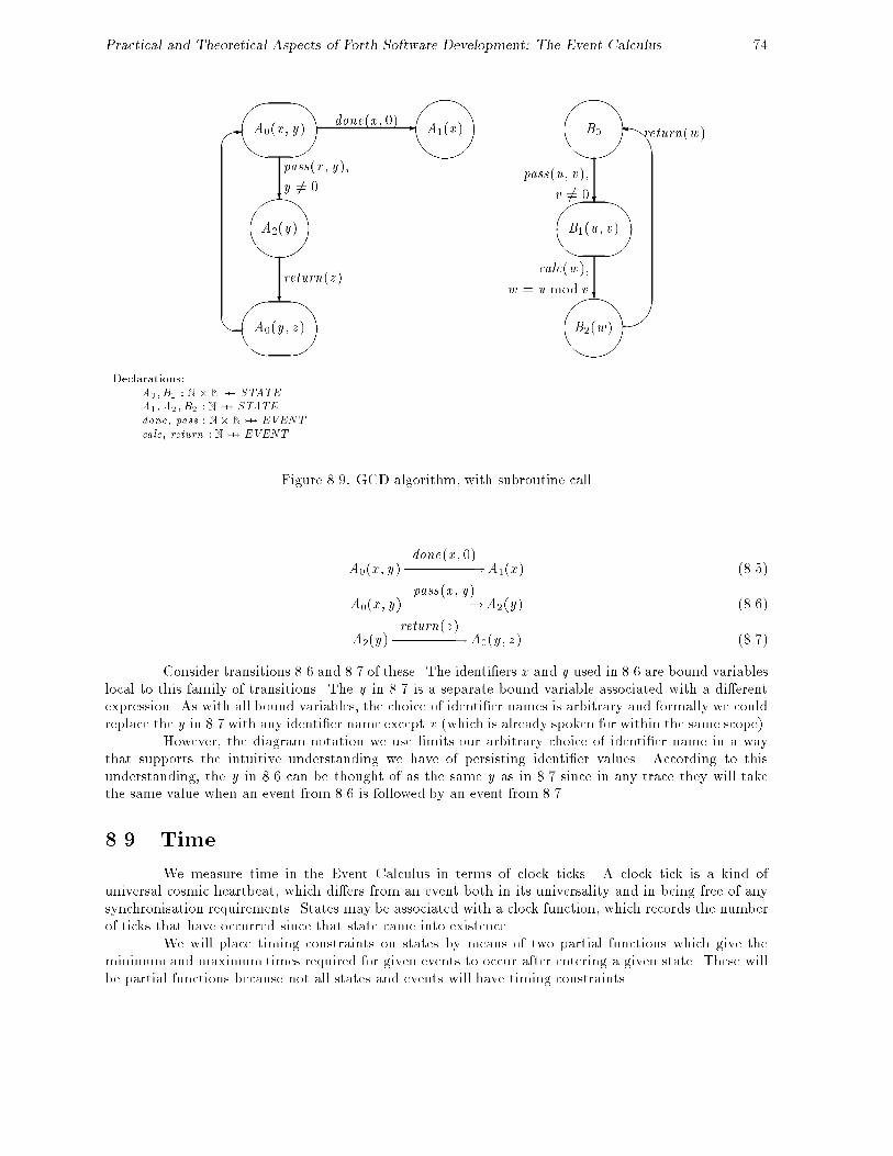
Practical and Theoretical Aspects of Forth Software Development: The Event Calculus 74
&%'$
&%'$
&%'$
&%'$
A0(x ; y)
A2(y)
A0(y ; z )
A1(x ) B0
B1(u; v)
B2(w)
�return(w)
pass(u; v);
calc(w);
w = u mod vreturn(z )
done(x ; 0)
v 6= 0y 6= 0
pass(x ; y);
#" !
#" !
#" !
?
?
?
?
!
�
�
- -
Declarations:A0;B1 : N�N 7� STATE
A1;A2;B2 : N 7� STATE
done; pass : N� N 7� EVENT
calc; return : N 7� EVENT
Figure 8.9: GCD algorithm, with subroutine call
A0(x ; y)done(x ; 0)���������!A1(x ) (8.5)
A0(x ; y)pass(x ; y)��������!A2(y) (8.6)
A2(y)return(z )��������!A0(y ; z ) (8.7)
Consider transitions 8.6 and 8.7 of these. The identi�ers x and y used in 8.6 are bound variableslocal to this family of transitions. The y in 8.7 is a separate bound variable associated with a di�erentexpression. As with all bound variables, the choice of identi�er names is arbitrary and formally we couldreplace the y in 8.7 with any identi�er name except x (which is already spoken for within the same scope).
However, the diagram notation we use limits our arbitrary choice of identi�er name in a waythat supports the intuitive understanding we have of persisting identi�er values. According to thisunderstanding, the y in 8.6 can be thought of as the same y as in 8.7 since in any trace they will takethe same value when an event from 8.6 is followed by an event from 8.7.
8.9 Time
We measure time in the Event Calculus in terms of clock ticks. A clock tick is a kind ofuniversal cosmic heartbeat, which di�ers from an event both in its universality and in being free of anysynchronisation requirements. States may be associated with a clock function, which records the numberof ticks that have occurred since that state came into existence.
We will place timing constraints on states by means of two partial functions which give theminimum and maximum times required for given events to occur after entering a given state. These willbe partial functions because not all states and events will have timing constraints.

Practical and Theoretical Aspects of Forth Software Development: The Event Calculus 75
We also introduce the set timed which is the set of all time constrained STATE �EVENT pairsand the set timed states, which is the set of states which have any time constrained events.
minreq;maxreq : STATE � EVENT ! N
timed : STATE � EVENT
timed states : PSTATE
timed = domminreq = dommaxreq
^timed states = fs : STATE j 9 e : EVENT � (s; e) 2 timedg
^8 s : STATE ; e : EVENT � ((s; e) 2 timed ) minreq s � maxreq s)
^
8 s : STATE ; e : EVENT � (s; e) 2 timed ) : (se��! s)
In the next section we will formally introduce a clock function as part of the system state.States which are subject to timing constraint have an associated clock which records how long they havebeen in existence, any new time constrained state that results from the event has its clock initialised tozero. Note that the �nal predicate of the above schema is to disallow null transitions from being timeconstrained. This is to avoid having to decide whether a null transition should reset a state clock.
Since timing constraints place additional restrictions on whether events can occur, we will hence-forth distinguish \enabled events" (those capable of occurring if timing restraints are not considered) from\�rable events" (those capable of occurring given that timing constraints are to be taken into considera-tion). All �rable events are necessarily enabled, but not all enabled events need be �rable.
In de�ning what we mean by a �rable event we make use of the functions minreq and maxreqas follows. A time constrained state s must exist for at least minreq(s; e) ticks before event e can occur.After s has persisted for minreq(s; e) ticks the event e may occur if it is �rable, but another clock tick(or another enabled event) may occur instead. After s has persisted for maxreq(s; e) ticks or longer, theevent e will occur before the next clock tick if it can. However, another tick may occur if e is not enabled.Even if e is enabled it may not occur as there may be other �rable events which may occur instead.
Figure 8.10 shows a simple mutual exclusion model with time constraints on the states ofmachines A and B .
Figure 8.11 shows a partial graph of the possible behaviours of the composite machine shownin �gure 8.10. In this graph we use the notation (s; n) to show that the timed state s has persisted forn clock ticks. Thus (A0; 2) indicates that state A0 has persisted for 2 clock ticks.
Initially, although the events get(A) and get(B) are enabled, they are not �rable because oftiming constraints. After the �rst clock tick the event get(B) becomes �rable. We now have a choice ofpossible behaviours consisting of another clock tick or the event get(B).
The trace consisting of \tick ; tick", brings us to a composite state where B0's clock has reachedmaxreq(B0; get(B)). Some event must now occur before the next clock tick. Two events are �rable,get(A) and get(B). If get(B) now occurs we enter the composite state:
f(A0; 2); S1(B); (B1; 0)g
State B1 is a new member of the compound state and has its clock initialised to zero.If, on the other hand, get(A) occurs we enter the composite state:
f(A1; 0); S1(A); (B0; 2)g
Now although B0's clock has reached maxreq(B0; get(B)) the event get(B) is not enabled. Atthis point a tick can occur, or the event rel(A) can occur.
The form of the timing constraints was chosen to allow the modelling of interrupts, time outsand to allow maximum and minimum times for complex behaviours to be calculated. We base these

Practical and Theoretical Aspects of Forth Software Development: The Event Calculus 76
&%'$&%'$#
"
!
�
-
A0
A1get(A)
rel(A)
&%'$&%'$#
"
!
�
-
S0
S1(p)get(p)
rel(p)
&%'$&%'$#
"
!
�
-
B0
B1get(B)
rel(B)
Declarations:get ; rel :MACHINE 7� EVENT
S1 : MACHINE 7� STATE
Timing Constraints:minreq = f((A0; get(A)); 2); ((A1; rel(A)); 0); ((B0; get(B)); 1); ((B1; rel(B)); 1)gmaxreq = f((A0; get(A)); 3); ((A1 ; rel(A)); 1); ((B0; get(B)); 2); ((B1; rel(B)); 1)g
Figure 8.10: Timing constraints example
calculations on the maximum and minimum times required for the possible event sequences that makeup the behaviour.
Consider the event sequence:
get(A); rel(A); get(B); rel(B)
We can deduce the minimum time this sequence can take by generating a trace which includes theseevents and which will always prefer an event to a clock tick:
tick ; tick ; get(A); rel(A); get(B); tick ; rel(B)
and we can deduce the maximum time by generating a trace which always prefers a tick to an event:
tick ; tick ; get(A); tick ; rel(A); get(B); tick ; rel(B)
A formal speci�cation of the timing rules for the system requires a notion of current systemstate, which is given in the following section.
8.10 The Dynamic model
Until now our formalisation of the Event Calculus has used a static model, in the sense thatour next state functions have held information from which all possible behaviours of an Event Calculusmodel could be deduced.
We now supplement this static description with a dynamic model which has a notion of thecurrent system state. As part of this model we introduce schemas to describe how the current state isupdated by the occurrence of an event or a clock tick.
The \data base schema" for the dynamic model records the composite current state and theclock value of each time constrained state within this composite state.

Practical and Theoretical Aspects of Forth Software Development: The Event Calculus 77
f (A1; 0); S1(A); (B0; 2) g
f (A1; 1); S1(A); (B0; 3) g
f (A0; 2); S1(B); (B1; 0) g
f (A0; 2); S0; (B0; 2) g
f (A0; 1); S0; (B0; 1) g
f (A0; 0); S0; (B0; 0) g
f (A0; 1); S1(B); (B1; 0) g
tick
tick get(B)
get(B)get(A)
tick
?
��
��
���+
?
QQQQQQQs
QQQQQQQs
��
��
���+
Figure 8.11: Partial graph of behaviours for the machine of �gure 8.10
MachineState
machines : PMACHINE
current state : validstatesetclock : (timed states \ current state) 7! N
�rable : EVENT ! B
machine (j current state j) = machines
8 e : EVENT ��rable(e) = enabled(current state;e)^8 s : current state �
(s; e) 2 timed ) clock s � minreq(s;e)
In this schema we declare the set of machines to be modelled, a set of states which gives thecurrent state of each of these machines and a clock function to give the clock value associated with eachtime constrained state. We also declare a boolean function which tells us whether a given event mayoccur (is �rable) in the given system state. An event may �re if it is enabled and if all time constrainedstates that will change as a result of the event have clocks that are past their minimum tick values.
We next describe the changes caused by �ring an event.

Practical and Theoretical Aspects of Forth Software Development: The Event Calculus 78
FireEvent
�MachineState
e? : EVENTresult ! : f\ok"; \cannot fire"g
�rable e?^ current state 0 = (�machines)(current state;e?)^ clock 0 = ((current state)�C clock)[
fs : timed states j s 2 current state 0 n current state � s 7! 0g^ result ! = \ok"
_: �rable e?^ current state 0 = current state
^ clock 0 = clock
^ result ! = \cannot fire"
If an event which can �re is input, the new composite state is found by applying the compositenext state function �. Any new time constrained state that results from the event has its clock initialisedto zero and the message \ok" is output.
If an event is input which cannot �re the system state does not change and the message \cannot�re" is output.
The �nal fundamental aspect of our dynamic model is the clock tick. This increments the clockvalue associated with each time constrained state in the current state space. However, there are somecircumstances in which a tick cannot occur. Suppose we have one or more state event pairs (s; e) suchthat e is a �rable event and clock s � maxreq(s; e). Then an event must occur before the next clock tick.
Tick
�MachineState
result ! : f\ok"; \an event must occur before the next tick"g
current state 0 = current state
^ (: 9 e : EVENT � (�rable e ^9 s : dom clock � clock s � maxreq(s;e)) ^
clock 0 = fs : STATE ;n : N j s 7! n 2 clock � s 7! n + 1g^ result ! = \ok")
_(9 e : EVENT � �rable e ^
9 s : dom clock � clock s � maxreq(s;e)^ clock 0 = clock
^ result ! = \an event must occur before the next tick")
8.11 Combining the Event Calculus with Z schema calculus
Data base operations are typically described in Z by �rst giving a data base schema:
S0 b= [D0 j P0 ]
then de�ning operations on this data base with schemas having a general form:
S1 b= [�S0; D1 j P1 ]
The declaration D0 will give the data structures of the data base. The predicate P0 will describedata base invariants. D1 will declare Input/Output identi�ers associated with the update. P1 will giveany restrictions and preconditions on the form of these identi�ers and will also describe how the newsystem state D 0
0 is related to the previous system state D0.

Practical and Theoretical Aspects of Forth Software Development: The Event Calculus 79
Suppose that in an event calculus model the state of this data base is maintained by a machineM . We will provide an interpretation for a \Schema Transition" of the form:
M0(S0)S1��!M1(S
0
0)
such that the Schema Transition describes, in terms of the event calculus, the data base update describedby the schema S1 in Z.
In formulating this interpretation we face certain di�culties. Firstly, in the Event Calculus,parameterised events accept tuples as arguments and identify arguments by their position within thetuple. In Z schemas, on the other hand, declarations do not have any particular order and arguments areidenti�ed by name. To handle this problem, we extend Z with an alphabetic ordering symbol � so thatif D is a declaration, �D will be the same declaration with its components written in alphabetic orderby identi�er name. Thus if X and Y are basic types and:
D is x ; z : X ; y : Y
then�D is x : X ; y : Y ; z : X
In addition, we use �D to represent the type obtained from the declaration D by taking thecartesian product of the types of its identi�ers in the order in which they are written, following Spivey(1989) we use �D to represent the characteristic tuple formed by writing out the identi�ers of D . Forexample
�(�D) is X � Y �X
and�(�D) is (x ; y ; z )
These notations will allow us to construct certain tuples required in our event calculus model.There is also a problem with respect to identi�er scope. In a parameterised labelled transition,
identi�ers are bound variables the scope of which is the labelled transition together with any qualifyingpredicate. Thus
A0(x )step(y)������!A1(z ); (y < x ^ z = x � y)
could equally well be written as:
A0(a)step(b)������!A1(c); (b < a ^ c = a � b)
In a schema, on the other hand, any identi�ers declared in the schema have a scope which laststill the end of the schema but may subsequently be reintroduced into the formal discussion by quoting theschema name. To overcome this discrepancy we use universal schema quanti�cation. If D is a declarationrestricted by a property P and if S is a schema, the declaration part of which includes all the identi�ersof D such that S can be expressed in the form:
S b= [D ; Ds j Ps ]
then8D j P � S
represents the schema[Ds j (8D j P � Ps ) ]
In our usage of this notation, D and P will be the declarations and predicate of the schemadescribing the data base update. Ds and Ps are the additional declarations and predicates required todescribe the labelled transition which will perform the data base update in the event calculus model.

Practical and Theoretical Aspects of Forth Software Development: The Event Calculus 80
We need some �nal conventions to generate the declarations of the parameterised states and theparameterised event needed in the event calculus model. We derive their names from those used in theschema transition
M0(S0)S1��!M1(S
0
0)
We take M0 and M1 as the names of our parameterised state functions. We obtain the pa-rameterised event function name by converting the �rst character of the data base update schema S1 tolower case. We represent this name informally as s1. This usage is informal because it does not show thederivation of the name s1 from the name S1. For example, if the name of the data base update schemais Book , the corresponding parameterised event name is book .
We are now ready to give the event calculus interpretation of the schema transition:
M0(S0)S1��!M1(S
0
0)
where S0 is a data base description schema
S0 b= [D0 j P0 ]
and S1, which describes a data base update operation, has the form:
S1 b= [�S0;D1 j P1 ]
Our interpretation of this text at the event calculus level will be:
8D0; D0
0; D1 � S
where
S
S1;M : MACHINE
M0;M1 : ��D0 7! states M
s1 : ��D1 7! EVENT
M0(��D0)s1(��D1)��������!M1(��D
0
0)
8.12 A Distributed seat booking system
As an example of the techniques described above, we specify a simple seat booking system inwhich bookings can be made from a number of di�erent nodes. We use Z schemas to describe the database and the update and enquiry operations to be performed upon it. We use an Event Calculus diagramto describe the manner in which each node is able to gain access to the data base. Together with therules of interpretation given above, these two parts of the system description generate a formal model, inZ, of the next state functions for the system's component state machines.
We introduce two basic types, the set of all seats and the set of names for people who may bookthe seats.
[SEAT ;NAME ]
The state of the data base is described in the following schema using a function from seats tonames. Seats which are not in the domain of this function are still free. There is an implicit invariantwhich disallows double booking of a seat. This invariant arises from the declaration of the relationshipbetween seats and names as a partial function.

Practical and Theoretical Aspects of Forth Software Development: The Event Calculus 81
Booking
booked : SEAT 7! NAME
free : PSEAT
free = SEAT n dom booked
We specify an enquiry operation which will return the set of free seats.
Enquire
�Bookingfree! : PSEAT
free! = free
We specify an operation to book a seat. The operation takes as inputs a seat and a name. Ithas the precondition that the given seat should not be already booked and, if this is satis�ed, it addsthe new booking to the data base. There will be no need to specify what happens if the seat is alreadybooked, as the event calculus part of the speci�cation will render this event impossible by specifying adata validation check.
Book
�Bookingseat? : SEATname? : NAME
seat? 2 free
booked 0 = booked [ fseat? 7! name?g
We now associate these schema with an Event Calculus diagram that models a system in whichmultiple nodes are able to share access to the data base. Figure 8.12 shows an Event Calculus diagramwhich, together with the seat booking speci�cation, provides the formal speci�cation for the system.
The seat bookings data base is maintained by machine A. There are two possible operationswhich can be performed on the data base, a seat booking and an enquiry. These are denoted in the EventCalculus diagram by writing:
Book _ Enquire
This declares the two schema transitions:
A0(Booking)Book�����!A0(Booking
0)
and
A0(Booking)Enquire�������!A0(Booking
0)
There is a possible ambiguity of notation here since the expression
Book _ Enquire
could also be taken to be a single schema formed by the \schema or" of Book and Enquire. To avoidthis, we do not allow schema expressions other than schema names to be written on an event calculusdiagram.
The data base update that occurs when a seat is booked is described by the schema transition:
A0(Booking)Book�����!A0(Booking
0)
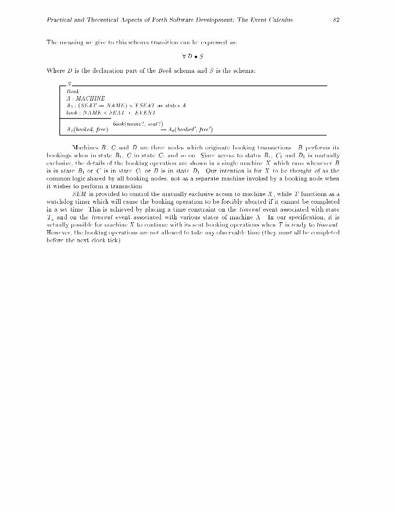
Practical and Theoretical Aspects of Forth Software Development: The Event Calculus 82
The meaning we give to this schema transition can be expressed as:
8D � S
Where D is the declaration part of the Book schema and S is the schema:
S
Book
A : MACHINE
A0 : (SEAT 7! NAME)�PSEAT 7! states A
book : NAME � SEAT 7! EVENT
A0(booked ; free)book(name?; seat?)����������������!A0(booked
0; free 0)
Machines B , C and D are three nodes which originate booking transactions. B performs itsbookings when in state B1, C in state C1 and so on. Since access to states B1, C1 and D1 is mutuallyexclusive, the details of the booking operation are shown in a single machine X which runs whenever Bis in state B1 or C is in state C1 or D is in state D1. Our intention is for X to be thought of as thecommon logic shared by all booking nodes, not as a separate machine invoked by a booking node whenit wishes to perform a transaction.
SEM is provided to control the mutually exclusive access to machine X , while T functions as awatchdog timer which will cause the booking operation to be forcibly aborted if it cannot be completedin a set time. This is achieved by placing a time constraint on the timeout event associated with stateT1 and on the timeout event associated with various states of machine X . In our speci�cation, it isactually possible for machine X to continue with its seat booking operations when T is ready to timeout .However, the booking operations are not allowed to take any observable time (they must all be completedbefore the next clock tick).

Practical and Theoretical Aspects of Forth Software Development: The Event Calculus 83
&%'$&%'$
&%'$
&%'$
&%'$
�
&%'$T1
T0
B1
C1
D1
D0
C0
B0
A0(Booking) SEM0
SEM1(p)
�
�
�-
�
-
�
�
�
�
-
�
�
�
&%'$
�
&%'$�
�
�-
A0(Booking 0)
? #" !
#" !
&%'$
&%'$&%'$&%'$
&%'$
X0
X1
X2
X3(free)
X4(free; seat)
X5(name; seat)
X6X7
reset
#" !
?
?
?
�
����������
set
reset
_timeout
get(B)
rel(B)
rel(C )
get(C )
get(D)
rel(D)
�
�
�
�-
�rel(p)
get(p)
Book_
Enquire
get(p)
set
enquire(free)
in1(seat)
in2(name);seat 2 free
book(name; seat)
timeout
timeout
abort ;seat 62 free
timeout
timeout
��
��
?
?
?
$
%
'-
��������������
rel(p)
#"
!
#"
!
��
��
�
�
-
�����/
$
%�
��
$
%66
Declarations: Time Constraints:
A0 : (SEAT 7! NAME) �PSEAT 7� states A
X4 : PSEAT � SEAT 7� states X
X5 : NAME � SEAT 7� states X minreq(T1; timeout) = 10
X3 : PSEAT 7� states X maxreq(T1; timeout) = 10
S1 :MACHINE 7� states S maxreq(X2 ; timeout) = 0
enquire : PSEAT 7� EVENT 8s : range X3 � maxreq(s ; timeout) = 0
book : NAME � SEAT 7� EVENT 8s : range X4 � maxreq(s ; timeout) = 0
get; rel :MACHINE 7� EVENT 8s : range X5 � maxreq(s ; timeout) = 0
in1 : SEAT 7� EVENT
in2 : NAME 7� EVENT
Figure 8.12: Seat booking, with mutual exclusion & time out

84
Chapter 9
Conclusions and Recommendations
In this project, our aim has been to develop software tools and formal notations that facilitatesoftware development in the Forth programming environment with a particular interest in \Real-Time"and safety critical systems. In this chapter, we provide an overview of the project, linking the variousparts, giving comments on the work and making suggestions for possible further work.
9.1 Introduction
Our initial areas of investigation were:
� To provide a method of communicating between multiple Forth-based RISC systems.
� A version of the Forth++ compiler to operate with the Harris RTX{2000 stack based RISCprocessor. This compiler also includes an extensive native-code optimisation technique.
� An interface between Forth and a local area network. This is to provide a multi-platform devel-opment environment. The interface can also be used to pass messages between di�erent (possiblyremote) nodes.
� The interfaces between Forth and other high-level languages, allowing the developer the freedomto interface with supplier propriety code. This was done in such a way that Forth's interactiveuser interface is maintained and may be used to enhance the original (non interactive) system.
We have been able to address some of these problems directly. We have described these invarious sections: Communicating Novix NC4016s (Appendix A); Forth++ and the Harris RTX{2000(Appendix B); Using Ibm's NetBios from Forth (Chapter 2); Mixed Language Interface (Chapter 3and Appendix C).
Many aspects of our investigations proved to be dependent on a more thorough theoreticalunderpinning of the Forth language. Thus our attention moved to providing such an underpinning.This work mainly consisted of:
� We looked at how formalisms might be used to de�ne a semantic model of the Forth language.We have provided a formal base from which the semantic meaning of a program can be derived(Chapter 4).
� In de�ning our formal base we found a relationship between the stack based virtual machine and aregister based target processor. We investigated this relationship, developing a single pass optimi-sation method (Chapter 5).

Practical and Theoretical Aspects of Forth Software Development: Conclusions/Recommendataions 85
� When using our formal de�nition we found that the parameter stack was a source of uncertainty.The stack is type free, yet to formally de�ne the meaning of a routine we must know the type ofthe stack items. We therefore investigated the possibility of developing a typed version of Forth,developing a \type signature algebra" that allows us to type check the Forth parameter stack(Chapter 6).
Having de�ned a type signature algebra we then investigated how this may be implemented andwhat e�ect it may have on a program (Chapter 7).
� In order to support the multi-tasking capabilities of Forth we developed a (formal) theory ofconcurrent tasks based on state machines that synchronise on events.
As this system is to be used by people unfamiliar with formal notations we have provided a graphicalrepresentation of the theory (Chapter 8).
9.2 Networks
We investigated the Ibm NetBios system as a standard for interfacing with lans. The Net-Bios system is designed to operate in parallel with any application. Chapter 2 describes an interfacethat we have developed to exploit this ability. We have also developed several demonstration programsto show how this system can be used to pass messages from one Ibm Pc to another.
9.3 Mixed Languages Interface
Our mixed languages interface is an interface between the Forth programming environmentand another programming language. The system described in Chapter 3 is designed to interface withcode written in the C language, however, the method is largely language independent thus allowing thedeveloper to interface with code written in any language. Although the system was written with theMicrosoft C compiler in mind, it was developed using Borland's Turbo C compiler. We have tested the\portability" of this system by compiling the same code under a number of di�erent compilers.
This interface has shown how we can tap into the ever growing pool of application librariesavailable for C (and other languages), thus reducing the maintenance and manufacturing costs of oursystem while providing more functionality.
We have seen one implementation of the general method of integrating these language features.We can see how the general methods can be used to extend the Forth system into areas that were outof reach. This system would allow us to indulge in hiding of information that the Forth system has norequirement to access in the C system, such as the oating point stack in Appendix C.
There are several ways in which this work could be advanced. It should be possible to providea Forth to C interface on a remote target system or a Pascal or even an Ada interface based on theseideas. It would also be possible to apply this interface to other Forth systems with relative ease.
9.4 Formal Forth
Several aspects of our investigations appear to be dependent on a more thorough theoretical un-derpinning of the language. Thus we moved our attentions to providing such support. Due to the natureof the Forth abstract machine it is possible to provide a set of tools that will aid a designer/programmerin ascertaining whether a Forth program meets its (formal) speci�cation. Chapter 4 shows some pre-liminary investigations in to how formal descriptions can be applied to parts of the Forth programmingenvironment.

Practical and Theoretical Aspects of Forth Software Development: Conclusions/Recommendataions 86
9.5 Stack Optimisation
We investigated the relationship between the Forth virtual stack machine and a register basedhost processor. In developing our formal support (Chapter 4) we modelled the stack as a sequence ofuntyped elements. This has lead to the development of a compiler optimisation technique based onthis concept. Chapter 5 reviews the more common optimisation techniques and develop our own \stackregisters" technique. This technique keeps the top three elements of the stack in internal registers. Unliketraditional systems that keep the items in speci�c registers, our system allocates the internal registersdynamically. We use a relationship between the top elements of the stack and their allocated register toproduce a stack image. Using this technique it is possible to obtain 100% optimisation on certain stackmanipulation operations (such as SWAP, ROT and DROP).
By combining the most common existing techniques (inline compilation, and peep-hole optimi-sation) with our stack registers we can provide a very powerful optimising compiler.
9.6 Type Algebra
Traditionally the Forth parameter stack has always been typeless. This allows the programmerto \cast" data items without recourse to ine�cient and unnecessary subroutines (as in C). The majorityof Forth programmers use this ability (either directly or indirectly) in almost all applications. Yet itcarries with it the problem that the programmer must keep track of the logical type of all the items he isusing. It would be possible to fetch an integer from a variable, thinking that it was an execution-token,causing the system to crash when this pseudo execution-token was executed.
In developing our formal support we found that we had to leave the stack as a sequence ofuntyped elements. Although we could reason about the logic of a program, we need to know the stacktypes to be able to check if a program is \correct" or not. For this we would need to provide some formof typing mechanism.
Jaanus P�oial of Tartu University has developed a \Stack Type Algebra" (P�oial 1990) thatprovides the capability of checking the type of stack elements. Chapter 6 presents a new type algebrabased on these ideas. The algebra includes the capability of handling items of variable type in additionto catering for program structures and conditional execution.
Using our type algebra, it would be possible to say that a program handles its stack correctly.It is not possible to say that the program will perform as required. By combining the type algebra withthe formal toolset, given in Chapter 4, it should be possible to formally prove that a Forth programhas a given property. In this way, we can prove that the Forth program has the same properties as thespeci�cation and is thus a true implementation of that speci�cation.
9.7 Forth Type Checker
Having developed our \type algebra" we investigated the possibility of implementing a Forthtype checker based on these ideas. Chapter 7 presents an initial speci�cation for such a program, referredto as \Flint". The speci�cation also allows the program to check for a number of additional errors (suchas stack under ow) and various software metrics in addition to its type checking role. Such a system willstop the abuse of the typeless stack whilst maintaining the exibility of a type free stack.
Although we have speci�ed a possible type checker and some thought to its initial design hasbeen incorporated in this speci�cation, we have not, as yet, developed the system. A commercial vendorhas shown an interest in this work and may develop an implementation.

Practical and Theoretical Aspects of Forth Software Development: Conclusions/Recommendataions 87
9.8 The Event Calculus
The \Event Calculus" is a diagrammatic notation that provides an easily used means of for-mally specifying the behaviour of concurrent systems. It can describe synchronous and asynchronouscommunications, data ow modelling and function application, in addition to temporal constraints. Italso abbreviates the description of complex state changes such as data base updates via the use of formalnotations. This gives the designer a good level of control over the levels of abstraction used.
Chapter 8 introduces the Calculus in a tutorial like manner, initially introducing the notationthen building up its functionality one step at a time. The formal de�nition of the Calculus is givenalongside an informal introduction to the notation.
We have found that the diagrammatic nature of the Calculus makes it relatively easy for nonspecialist to use when compared to other (event based) process algebras such as csp, ccs and lotos. Asa speci�cation produced using the Calculus has an underlying formal speci�cation, it is possible to usethis speci�cation for deriving proofs of the system begin modelled.
The Calculus is used to not only represent the state transitions in one system but also theinteraction between di�erent state machines. There is a very simple correlation between a state machineas represented in the Calculus and a Forth task. Indeed, the Calculus appears to be an e�ectivemechanism for breaking down a complex problem into a multi-tasking implementation.
9.9 Future Directions
In this section we describe how the work presented in this document could be extended. Wehave identi�ed three areas of interest that we feel worthy of further development.
9.9.1 Type Algebra
The type algebra can be developed further:
� The rules for handling variable types (rules 5{8) are probably not required, they can be derivedfrom the matching rules (rules 1{3) and the reduction rule (rule 4).
� The \Multiple Signature" (+) and \Alternative Type" (|) capabilities are the only way subtypescan be expressed at current. The provision of a types hierarchy should be investigated.
� The implementation of the algebra in some form of automatic tool, such as Flint, or by incorpo-rating the algebra into an existing compiler.
9.9.2 Formal Forth
It is our intention to provide a secure Forth programming environment. We intend to producesuch a system on a Windows based workstation, such as a Sun (Sparc station) or an Ibm Pc underWindows. This system should be a formally speci�ed standard Forth implementation1. The formalspeci�cation, probably written in Z, will be based on the preliminary \Formal Forth" work.
We would like to include type checking facilities based on the type algebra, similar to thoseprescribed for the Flint program. In time we would like to extend this system to include a formalisedvariant of the stack registers optimisation technique.
1Probably the Ansi Standard, when it is released.

Practical and Theoretical Aspects of Forth Software Development: Conclusions/Recommendataions 88
9.9.3 Event Calculus
The interface between an event and a Z Schema is perhaps more complicated than is necessary.This interface should be investigated, a new less complex one should be provided if possible.
The Event Calculus should be used to generate some example speci�cations. Taking a numberof case studies from initial speci�cation, through to �nal implementation (in Forth), complete withcorresponding proofs. This will also provide us with a less formal introduction to the Calculus.
Such examples could be used to introduce the Forth community to formal methods whilst theEvent Calculus could be used to introduce the formal methods community to the Forth language.

89
Bibliography
Aho, A. V., R. Sethi, and J. D. Ullman (1986). Compilers: Principles, Techniques, and Tools. Reading,MA: Addison-Wesley.
Almy, T. (1987). Compiling of Forth for performance. Journal of Forth Application and Re-search 4 (3), 379{388.
ANSI (1991). ANS ACS X3/X3J14 Programming languages | Forth: Draft Standard (�rst ed.).American National Standards Institute.
Astle, R. (1985). Yet another recursive decompiler. In Proc. FORML Conf., San Carlos, CA. ForthInterest Group.
Bailey, G. V. et al. (1987, February). PolyForth ISD-4 NC4000 CPU Supplement. Manhattan Beach,CA: FORTH Inc.
Borland International (1988). Turbo C Reference Guide. Scotts Valley, CA: Borland International.Version 2.
Borland International Inc. (1988). Turbo C User's Guide. Scotts Valley, CA: Borland InternationalInc. Version 2.
Bowen, J. P. (1987, January). The formal speci�cation of a microprocessor instruction set. TechnicalMonograph PRG-60, Oxford University Computing Laboratory, Oxford.
Bradley, M. (1985). Self-understanding programs. In Proc. FORML Conf., San Carlos, CA. ForthInterest Group.
Bradley, M. and M. Saari (1988). Sun Forth User's Guide. Mountain View, CA: Bradley Forthware.
Brinksma, E. and T. Bolognesi (1987). Introduction to the ISO speci�cation language LOTOS. Com-puter Networks and ISDN Systems 14, 25{59.
Brodie, L. (1982). Starting Forth (second ed.). London: Prentice Hall International.
Brodie, L. (1984). Thinking Forth. London: Prentice Hall International.
Bruno, J. and T. Lassagne (1975). The generation of optimal code for stack machines. Journal of theACM 22 (3), 382{396.
Buege, B. (1984). A decompiler design. In Proc. FORML Conf., San Carlos, CA. Forth InterestGroup.
Carr, H. and R. R. Kessler (1986). Forth and AI? Journal of Forth Application and Research 4 (2),177{180.
comp.lang.forth (1987{1992). Usenet newsgroup.

Practical and Theoretical Aspects of Forth Software Development: Conclusions/Recommendataions 90
Cook, R. and I. Lee (1980, 26{28 May). An extensible stack-oriented architecture for a high-level lan-guage machine. In Proc. of the International Workshop of High-Level Language Computer Architecture,Fort Lauderdale, FL, pp. 231{237.
Danile, P. and C. Malinowski (1987, June). Forth processor core for integrated 16-bit systems. VLSISystems Design 8 (7), 98{104.
Diller, A. (1990). Z: An introduction to Formal Methods. London: John Wiley & Son.
Dowling, T. (1981). Automatic code generator for Forth. In Proc. FORML Conf., San Carlos, CA.Forth Interest Group.
Du�, C. B. (1984). NEON | extending Forth in new directions. In Proc. FORML Conf., San Carlos,CA. Forth Interest Group.
Du�, C. B. (1986). ACTOR, a threaded object-oriented language. Journal of Forth Application andResearch 4 (2), 155{161.
Du�, C. B. and N. D. Iverson (1984). Forth meets SmallTalk. Journal of Forth Application andResearch 2 (3), 7{26.
Duncan, R. et al. (1988). The MS-DOS Encyclopedia. Redmond, WA: Microsoft Press.
Forth Interest Group (1980). Forth-79 Standard. San Carlos, CA: Forth Interest Group.
Forth Interest Group (1983). Forth-83 Standard. San Carlos, CA: Forth Interest Group.
Glass, B. (1989, January). Understanding NetBios. Byte, 301{306.
Golden, J., C. Moore, and L. Brodie (1985, March). Fast processor chip takes its instructions directlyfrom Forth. Electronic Design, 127{138.
Hand, T. (1988). Software metrics for Forth. In Proc. Rochester Forth Conf. on ProgrammingEnvironments, Rochester, NY, pp. 67{68. Institute of Applied Forth Research.
Hanson, D. R. (1980). Code improvement via lazy evaluation. Information Processing Letters 11 (4{5),163{167.
Harris, K. R. (1985). Analyzing large Forth programs by using the STRUCTURE-TOOL program.In Proc. FORML Conf., San Carlos, CA. Forth Interest Group.
Harris Semiconductor (1988a). Harris RTX-2000 Programmer's Reference Manual. Melbourne, FL:Harris Corporation.
Harris Semiconductor (1988b). RTX 2000 Instruction Set. Melbourne, FL: Harris Corporation.
Harris Semiconductor (1988c). RTX 2000 Real Time Express Microcontroller Data Sheet. Melbourne,FL: Harris Corporation.
Hayes, I. (Ed.) (1987). Speci�cation Case Studies. Computer Science. London: Prentice Hall Interna-tional.
Hoare, C. A. R. (1985). Communicating Sequential Processes. Computer Science. London: PrenticeHall International.
Ho�mann, U. (1991). Stack checking | a debugging aid. In Proc. EuroFORML Conf., San Carlos,CA. Forth Interest Group.
Ibm Corporation (1987, April). NetBios Application Development Guide. Ibm Corporation.

Practical and Theoretical Aspects of Forth Software Development: Conclusions/Recommendataions 91
Intel Corporation (1981, August). iAPX 86,88 User's Manual. Berkeley, CA: Intel Corporation.
Jennings, E. (1985, October). The novix NC4000 project. Computer Language 2 (10), 37{46.
Jones, T., C. Malinowski, and S. Zepp (1987, May). Standard-cell CPU toolkit crafts potent processors.Electronic Design 35 (12), 93{101.
Kavipurapu, K. and H. Cragon (1980, 26{28 May). Quest for an `ideal' machine language. In Proc. ofthe International Workshop of High-Level Language Computer Architecture, Fort Lauderdale, FL, pp.33{39.
Kernighan, B. W. and D. M. Ritchie (1988). The C Programming Language (Second ed.). Software.Englewood Cli�s, NJ: Prentice Hall International.
Knaggs, P. J. and W. J. Stoddart (1990). The Forth++ `C' interface. In Proc. FORML Conf., Proc.EuroFORML Conf., San Carlos, CA. Forth Interest Group.
Knaggs, P. J. and W. J. Stoddart (1991a). The cell type. In Proc. Rochester Forth Conf. on AutomatedInstruments, Rochester, NY, pp. 55{57. Institute of Applied Forth Research.
Knaggs, P. J. and W. J. Stoddart (1991b). Formal Forth. In Proc. Rochester Forth Conf. onAutomated Instruments, Rochester, NY, pp. 50{55. Institute of Applied Forth Research.
Knecht, K. (1982). Introduction to Forth. Indiana: Howard Sams & Co.
Kogge, P. M. (1982, March). An architectural trail to threaded code systems. IEEE Computer , 22{32.
Koopman, P. J. (1989). Stack Computers: The New Wave. Chichester: Ellis Horwood.
Lukasiewicz, J. (1963). Elements of Mathematical Logic (Second ed.), Volume 31 of International Seriesof Monographs in Pure and Applied Mathematics. Oxford: Pergamon Press Ltd. First published in1929.
Lyons, G. B. (1980). Compressed Forth object code. In Proc. FORML Conf., San Carlos, CA. ForthInterest Group.
Marriot, R. (1989a). MACH1 Hardware Reference Manual. Cranleigh, UK: Micro-Amps Ltd.
Marriot, R. (1989b). MACH2 Hardware Reference Manual. Cranleigh, UK: Micro-Amps Ltd.
McMorran, M. A. and J. E. Nicholls (1989, July). Z user manual. Technical Report TR12.274, IbmHursley Park. Version 1.0.
Microsoft Corporation (1984{85). Microsoft Macro Assembler. Redmond, WA: Microsoft Corporation.Version 4.0.
Microsoft Corporation (1984{87a). Microsoft C Language reference. Redmond, WA: Microsoft Corpo-ration. Version 5.
Microsoft Corporation (1984{87b). Microsoft C Run-Time Library Reference. Redmond, WA: MicrosoftCorporation. Version 5.
Microsoft Corporation (1984{87c). Microsoft C Users Guide. Redmond, WA: Microsoft Corporation.Version 5.
Microsoft Corporation (1984{87d). Mixed Language Guide. Redmond, WA: Microsoft Corporation.
Microsoft Corporation (1987). Code View and Utilities. Redmond, WA: Microsoft Corporation.

Practical and Theoretical Aspects of Forth Software Development: Conclusions/Recommendataions 92
Miller, D. (1987, April). Stack machines and compiler design. Byte 12 (4), 177{185.
Milner, R. (1989). Communication and Concurrency. Computer Science. London: Prentice HallInternational.
Minker, J. and R. G. Minker (1980). Oprimization of boolean expressions | historical developments.A. of the History of Computing 2 (3), 227{238.
Moore, C. (1974). Forth: a new way to program a mini-computer. Astronomy & AstrophysicsSupplement 15, 497{511.
Moore, C. (1980, August). The evolution of Forth: an unusual language. Byte 5 (8), 76{92.
Moore, C. (1990a). MuP20 Microprocessor: Preliminary Speci�cations. Woodside, CA: ComputerCowboys.
Moore, C. (1990b). ShBoom on ShBoom: A microcosm of software and hardware tools. In Proc.Rochester Forth Conf. on Embedded Systems, Rochester, NY, pp. 21{27. Institute of Applied ForthResearch.
Morgan, C. (1990). Programming from Speci�cations. Computer Science. London: Prentice HallInternational.
Morse, S. P. (1982). The 8086/8088 Primer (Second ed.). Chichester: Hayden Book Company.
Nash, T. (1989). Using Z to describe really large system. In Proc. Z Users Meeting, pp. 150{178.Oxford.
Nine Tiles (1987, September). Superlink Reference Manual. Cambridge, UK: Nine Tiles.
Nine Tiles (1988a, February). SimpleNet User Guide. Cambridge, UK: Nine Tiles.
Nine Tiles (1988b, June). SimpleNetBIOS Reference Guide. Cambridge, UK: Nine Tiles.
Novix (1985). Programmers' Introduction to the NC4000 Microprocessor. Cupertino, CA: Novix Inc.
Pawley, W. (1984). Using native machine code analogs of interpreted Forth's elements for highperformance. In Proc. Rochester Forth Conf. on Real Time Systems, Rochester, NY, pp. 115{120.Institute of Applied Forth Research.
Phillips, M. (1989). CICS/ESA 3.1 experiences. In Proc. Z Users Meeting, pp. 179{185. Oxford.
P�oial, J. (1990). The algebraic speci�cation of stack e�ects for Forth programs. In Proc. FORMLConf., Proc. EuroFORML Conf., San Carlos, CA. Forth Interest Group.
P�oial, J. (1991). Multiple stack e�ects of Forth programs. In Proc. EuroFORML Conf., San Carlos,CA, pp. 400{406. Forth Interest Group.
Rather, E. D. (1985). Forth. Computer Programming Management .
Rather, E. D. (1987). Forth programming language. Encyclopedia of Physical Science & Technology 5.
Rather, E. D., L. Brodie, et al. (1986, November). PolyForth ISD-4 Reference Manual (�fth ed.).Manhattan Beach, CA: FORTH Inc.
Rose, A. (1986). Design of a fast 68000-based subroutine threaded Forth with inline code & optimiser.In Proc. Rochester Forth Conf. on Arti�cal Intelligence, Rochester, NY, pp. 285{288. Institute ofApplied Forth Research.

Practical and Theoretical Aspects of Forth Software Development: Conclusions/Recommendataions 93
Schwaderer, W. D. (1988, August). C Programmer's Guide to NetBIOS. Indianapolis: Howard W.Sams & Company.
Scott, A. (1989). An extensible optimizer for compiling Forth. In Proc. FORML Conf., San Carlos,CA. Forth Interest Group.
Silicon Composers (1987a, March). PC4000 Board User Manual. Palo Alto, CA: Silicon Composers.
Silicon Composers (1987b, January). SCForth User Manual (second ed.). Palo Alto, CA: SiliconComposers.
Sjolander, S. (1987). Novix decoder. In Proc. FORML Conf., San Carlos, CA. Forth Interest Group.
Sjolander, S. et al. (1987, June). PolyForth ISD-4 Intel 8086 CPU Supplement (ninth ed.). ManhattanBeach, CA: FORTH Inc.
Spivey, J. M. (1989). The Z Notation: A Reference Manual. Computer Science. London: Prentice HallInternational.
Spivey, J. M. (1990, September). Specifying a real-time kernel. IEEE Software, 21{28.
Stephens, C. L. and R. M. Rodriguez (1986, July). PolyForth: an electronics engineer's programmingtool. Software Engineering Journal 1, 154{158.
Stoddart, W. J. (1984). Readable and e�cient parameter access via argument record. Journal ofForth Application and Research 3 (1), 61{82.
Stoddart, W. J. (1987). Nested error handlers. Journal of Forth Application and Research 4 (3),443{445.
Stoddart, W. J. (1988). Speci�cation & optimisation. In Proc. EuroFORML Conf., Southampton.MicroProcessor Engineering Ltd.
Stoddart, W. J. (1989a). Forth++ Course Notes | Part 1: An introduction to Forth. Middles-brough, UK: Teesside Polytechnic.
Stoddart, W. J. (1989b). Forth++ System Documentation. Middlesbrough, UK: Teesside Polytechnic.
Stoddart, W. J. (1990a). Forth++ Course Notes | Part 2: Multi-tasking and Windows. Middles-brough, UK: Teesside Polytechnic.
Stoddart, W. J. (1990b). Forth++ Course Notes | Part 3: Argument Records. Middlesbrough, UK:Teesside Polytechnic.
Stoddart, W. J. (1990c). MACH1 Forth++ evaluation system. Middlesbrough, UK: Teesside Poly-technic.
Stoddart, W. J. (1990d). RTX Forth++ MACH1 Speci�cs. Middlesbrough, UK: Teesside Polytechnic.
Stoddart, W. J. (1990e). RTX Forth++ Manual. Middlesbrough, UK: Teesside Polytechnic.
Stoddart, W. J. (1991a). Forth++ C/Forth Interface. Middlesbrough, UK: Teesside Polytechnic.
Stoddart, W. J. (1991b). Forth++ Extras: Graphics support and software Floating point. Middles-brough, UK: Teesside Polytechnic.
Stoddart, W. J. and P. J. Knaggs (1990). Forth++ and the MACH1 RTX-2000 board. In Proc.FORML Conf., Proc. EuroFORML Conf., San Carlos, CA. Forth Interest Group.

Practical and Theoretical Aspects of Forth Software Development: Conclusions/Recommendataions 94
Stoddart, W. J. and P. J. Knaggs (1991). Type inference in stack based languages. In Proc. Euro-FORML Conf., San Carlos, CA. Forth Interest Group.
Stoddart, W. J. and P. J. Knaggs (1992, September). The Event Calculus (Formal Speci�cation of RealTime Systems by means of Diagrams and Z Schemas). In Proc. 5th International Conf. on Putting intopractice methods and tools for information system design. University of Nantes, Institut Universitairede Technologie, 3 Rue du Mar�echal Jo�re, 44041 NANTES Cedex 01, France.
Surrey Medical Imaging Systems Ltd. (1988). PP2000 50 MIP parallel processor RTX-2000 Forthdevelopment board. Guildford, UK: Surrey Medical Imaging Systems Ltd.
Tanenbaum, A. S., H. van Staveren, and J. W. Stevenson (1982). Using peephole optimization onintermediate code. TOPLAS 4 (1), 21{36.
Wickes, W. C. (1988). RPL: A mathematical control language. In Proc. Rochester Forth Conf. onProgramming Environments, Rochester, NY, pp. 27{32. Institute of Applied Forth Research.
Woodcock, J. C. P. and M. Loomes (1988). Software Engineering Mathematics: Formal MethodsDemysti�ed. London: Pitman Publishing Ltd.
Zorland Inc. (1987). Zorland C Compiler. Zorland Inc. Version 2.
ZorTech Inc. (1989a). ZorTech C++ Compiler Compiler Reference. ZorTech Inc. Version 2.
ZorTech Inc. (1989b). ZorTech C++ Compiler Function Reference. ZorTech Inc. Version 2.

95
Appendix A
Communicating Novix NC4016s
At the start of this project we were given two Novix NC4016 boards. The intention being towork with these boards to provide systems that could communicate over multiple CPUs. The NovixNC4016 being a RISC based processor that is capable of executing a Forth program at great speed.
A.1 Introduction
The Novix processor is su�ciently small that it takes only 4000 gates in a programmable logicarray to implement. The chip has four di�erent data paths, it is possible to use all four within onemachine instruction, thus providing the capability of executing up to �ve Forth instructions in onemachine cycle. The majority of machine instructions are executed in one clock cycle. As a result a Novixsystem operating at 10 MHz has a peek e�ective throughput of 40 MHz or 40 MIPS (Million InstructionsPer Second).
The machine instructions of the Novix are designed to execute Forth. The Forth systemssupplied with the boards were designed to compile optimised native code for the Novix system.
In this annex we describe the Novix plug in boards in detail and describe how we made the twototally independent boards communicate with each other.
A.2 Programming
Four di�erent implementations of the Forth programming language were provided:
A.2.1 cmForth
This is an implementation by Chuck Moore. It is a basic system that has been modi�ed toexploit the abilities of the Novix. We found the Forth itself, whilst a valid implementation, to belacking in features1. This is used in conjunction with the SCForth system to provide a programmingenvironment on the Novix board.
A.2.2 SCForth
This is a system provided by Silicon Composers to operate on the Ibm Pc. It is a rather basicimplementation of the language that had been extended to allow communication with the Novix boards.Although the implementation is valid, it was of a rather basic system with few features.
1This is a common feature of all of Chuck's Forth systems.

Practical and Theoretical Aspects of Forth Software Development: Communicating Novix NC4016s 96
To use the Novix board, the user would load the SCForth system. He would then load thecmForth system into a 16 KBytes dual ported memory bu�er. The SCForth would then producean interrupt signal that instructs the Novix to start executing the cmForth system. This provides aprogramming environment on the Novix system and a support environment on the Ibm Pc.
Having set the Novix executing the cmForth system, and any application the user may haveloaded, he can then exit from the SCForth system back to the Ibm Pc's operating system. Thusleaving the Novix system to continue executing its application. This is only valid if the application doesnot require any facilities from the Ibm Pc \Host" (see section A.4), as these facilities have now beenremoved.
A.2.3 PolyForth
This is a fully implemented Forth development system. Two versions of the system are pro-vided. One operated on the Ibm Pc while the other operated on the Novix. This is a full Forthsystem with a full screen editor, multi-tasking and meta-compilation. The system also provided a targetcompilation system for use with the Novix.
The Novix PolyForth system is also a full development system. It has multi-tasking, meta-compilation and optimisation. As with the Silicon Composers system, the user has to load the PolyForthsystem. This will then load the Novix PolyForth system into the dual ported memory and set the Novixexecuting it. The Ibm Pc system provides \Host" services for the Novix system.
As with the Silicon Composers system, once the Novix system has been loaded and is executingan application, the Ibm Pc's PolyForth system may be removed providing that the Novix applicationdoes not require any of the \Host" facilities provided by the Ibm Pc software.
A.2.4 FATWIN
The \Forth with Argument records, Multi-Tasking and Windows" system developed by BillStoddart was supplied as a Forth system that operated on the Ibm Pc. This is a full implementationof Forth with many standard extensions and several non-standard features. Most of the extensions onthis system are provided in a manner that is compatible with the PolyForth implementation.
Whilst this system was of little interest when the project began it was latter developed into theForth++ system and has played a large part in this project (see chapter 1).
A.3 Single Boards
We were using the PolyForth system to develop the multi-processor communications systems.This operated correctly with the �rst of the two boards but not with the second. The location of thedual ported memory of the �rst board was at segment CC00 and segment D000 for the second.
All of the software in the Ibm Pc PolyForth system used the variable 'FB to hold the segmentaddress of the dual ported memory. The software in the Novix PolyForth system does not need to knowwhere this memory is located in the Ibm Pc, it simply uses the memory at 00000 though to 04000 as itscommunication area.
Thus we can change the board that the PolyForth system is communicating with simply bychanging the value stored in the 'FB variable. We de�ned two new words FB1 and FB2 to set the valueof 'FB to communicate with the �rst or second board as required. As the PolyForth system only copiesthe Novix PolyForth to the �rst board it is left to the user to \boot" the second board. This is doneby selecting the second board and typing the Forth word BOOT:
FB2 BOOT
Whilst this method of booting the second board works, we want to hide such information fromthe user. Thus, we redeveloped the code for FB1, FB2, BOOT (and PLUG) so that when the user selected a

Practical and Theoretical Aspects of Forth Software Development: Communicating Novix NC4016s 97
board that had not been initialised, the system would automatically copy the PolyForth system to thenew board and set it operating. The code that created the words FB1 and FB2 was developed in such away that the user can add new boards to the system at will. The code is given in section A.7.1.
A.4 Host Services
When the Forth word PLUG is executed the PolyForth system connects with the current Novixboard (indicated by the value of 'FB). The OPERATOR task is set up to provide \Host Services" to the Novixsystem. The purpose of this is to provide the Novix system with a method of accessing the Ibm Pc'shardware. The PolyForth system provides access to the Keyboard, Video, Disks, Communication Portsand Printer.
The mechanism by which these services are provided is that of a \Mailbox". One mailbox isused for each device that the system is supporting. The mailboxes are stored in the dual ported memory,thus being accessible by both the Novix and the Ibm Pc. The mailboxes are of di�ering length dependingon the device that they are controlling and the functions it can perform.
The Novix will place a value in the �rst word of the mailbox indicating the function it would liketo perform. The Ibm Pc will take this value and use it as an o�set into a table of functions2 executingthe required function. The Ibm Pc will place the value �1 in the mailbox to indicate to the Novix thatit has completed the requested function. Whilst this is not a very good Forth based approach to theproblem, it is the way the original PolyForth system operated. In our work, we have tried not to alterthe way in which the Novix communicates with the Host in any way thus we have inherited this messagepassing mechanism.
For the Novix to display a message on the Ibm Pc's screen, it would place the required text intothe bu�er area of the mailbox. It will then set a function code in the mailbox and wait for the Ibm Pcto acknowledge the function code. The Ibm Pc will interpret the function code and display the text inthe bu�er. Having completed the function it will send a message back to the Novix in the form of anacknowledgment. Having received the acknowledgment the Novix will now continue with its processing.
The system is designed in this way in order to provide multi-tasking on the Novix board. Letus say, for example, that two independent tasks on the Novix would like to access the same device. The�rst task would place its function code into the mailbox (and additional data if required). This taskwould then continue processing. However, the second task would see that the mailbox has a functionpending (ie, that the function request code is not �1) and so will wait (in a multi-tasking manner) untilthe Ibm Pc acknowledges the �rst task request by placing �1 in the request code area. The second taskcan now continue and place its request in the mailbox.
The PolyForth \Host" system has a task constantly monitoring the function request value foreach mailbox, with the exception of the Keyboard and Video mailboxes. When the Ibm Pc is PLUGed intothe Novix board the OPERATOR task monitors the Keyboard and Video mailboxes. One of the functionsassociated with this mailbox is \return to host". On receiving this request the OPERATOR reverts back toits normal action of interpreting keyboard commands for the Ibm Pc system.
A.5 Parallel Boards
The system described in sections A.3 and A.4 provides us with a mechanism that allows two (ormore) separate Novix boards operating in parallel. There are still two problems to be solved:
1. Only one Novix board may have access to the \Host" facilities at any given time. This access iscontrolled by the operator connecting with the relevant board (via the use of FB1 and FB2).
2. Although the boards may be operating in parallel, they are also operating in isolation. A methodthat allows the boards to communicate with each other is to be found.
2This means that the function numbers must be even.

Practical and Theoretical Aspects of Forth Software Development: Communicating Novix NC4016s 98
We see two methods of solving the �rst of these problems. Namely the provision of \Host"services to all of the Novix systems available.
A.5.1 First Method
The monitoring of the mailbox function request area is performed by the word AWAIT. The codefor AWAIT was redeveloped to scan for both Novix systems (see section A.7.2). Thus when the monitoringtask executed the AWAIT word it would automatically monitor both of the Novix boards. When AWAIT
returned the system would be ready to perform the required action for the correct board.
This system failed to operate to our expectations for various reasons:
1. The system is based around the ability of altering the value of the 'FB variable to indicate therelevant Novix board. This is a global variable, thus, changing its value, will e�ect other tasks. Asthe system is multi-tasking, it is not possible to change such a variable and expect its value to bethe same when next used.
This is a common problem when dealing with multi-tasking systems. By changing the 'FB variablefrom a global to a user variable, each task will have its own copy of the variable. Hence it can takeon di�erent values for each di�erent task.
2. The code (as given in section A.7.2) is explicitly written for use on two boards and is not capableof expansion (without rewriting it each time a new board is added).
By changing MAKE.FB we could make a cyclic list out of the possible Novix boards present. We arethen able to rewrite AWAIT to scan through the cyclic list of possible boards. Hence, when the usercreates another board, it would automatically be added to the list of boards. Thus, the monitoringsoftware will automatically start servicing it.
This has a problem in that the host will start servicing the board before it has been initialised. Bymoving the code that links the new board into this cyclic list to be the last function performed bythe FBOOT word we stop the host from servicing the new board until after it has been initialised.The code for this system is given in section A.7.3.
3. The DISKER task provides access to the disk system, via use of the disk mailbox. This is a shortmailbox holding two data �elds, the value #BLK indicating which disk block the Novix requires andthe value of BUFFER indicating whereabouts in the Ibm Pc's memory the block has been located.To read the contents of the disk block, the Novix issues keyboard input requests. The keyboardserver will take its input from the indicated block rather than the keyboard.
Whilst this is (in principle) the correct way of performing this function3 it has two problems:
(a) It relies on the interaction of two servicing tasks, the DISKER task (monitoring the disk mail-box) and the OPERATOR task (monitoring the keyboard/video mailbox). It is possible for theOPERATOR to be processing another board's request at the same time the DISKER request ismade. However, the OPERATOR will see the ag indicating it should take input data from thedisk block and will therefore pass the disk block information to the wrong Novix system.
(b) It means that the Novix system can only process disk information when the keyboard/videomailbox server is in operation. Ie, the board in question is connected.
If we were to \tighten up" the synchronisation between the two tasks, so that the OPERATOR taskwere to know for which Novix board the disk request applies, it would stop the �rst problem.However, the Novix system would still only be able to access the disk services when it has beenconnected too.
3Based on the description of disk accessing given in the Forth'83 standard.

Practical and Theoretical Aspects of Forth Software Development: Communicating Novix NC4016s 99
4. In order to communicate with the boards the user must connect with one of them (using the FB1
or FB2 words). This will set the OPERATOR task servicing the keyboard/video mailbox. However, asthe keyboard is being treated as a normal device two (or more) Novix system may make a requestto obtain input from the keyboard. One of the systems will be honoured, however, the user willhave no knowledge as to which system he is communicating. This relates to the previous problemof the disk accessing being directed through the keyboard/video mailbox.
By providing an additional task TERM that will service most of the keyboard/video mailbox requests,we can provide all of the boards with access to the video. We can also provide access to the disksystem by synchronising the TERM task with the disk accessing of the DISKER task. This will leavethe OPERATOR task to be used in the conventional manner.
The TERM task will be able to process requests for text from the keyboard under two circumstances:
(a) The Novix board making the request has previously made a request of the DISKER task (ie, isinputting a disk block).
(b) The OPERATOR task had been directed to operate as the keyboard for the Novix system makingthe request.
In this manner, we can provide a mechanism that allows any of the Novix boards to access theIbm Pc's disk drives. The user will be able to PLUG into any of the boards and know that allkeyboard communication is being directed to that board.
This solution still has a problem. When the user is connected to one of the boards, it will stop anyform of disk accessing. The Novix will issue a \Read data from the keyboard" request. While theTERM task is processing this request it will not be able to process any other requests. The solution tothis problem is to totally redevelop the functions provided by the disk mailbox such that it operatesindependently of the keyboard mailbox.
A.5.2 Second Method
The second method of provided this facility is to totally redevelop the servicing code. Byproviding a single task that scanned and processed all of the mailboxes connected with the one board itis possible to add as many tasks as required, each servicing its own Novix system.
Whilst this method is conceptually simpler than the �rst, it means a complete redevelopment ofthe existing code, the converging of several tasks into one. Although this made the problems of handlingthe disk and keyboard into simple problems.
A.5.3 Comparison
Both methods provided the environment that is required. The �rst method is more di�cult tounderstand and leads to complicated problems that were solved by redeveloping part of the server code(and the Novix code). It is simpler to use, as it is more automatic than the second method.
The second method is simpler to understand but requires a great deal more e�ort to totallyredevelop the servicing code, although no Novix code has to be changed. The coding has to take intoaccount the fact that several tasks may be requesting access to the same resource simultaneously whilst,in the �rst method, this is taken care of automatically (by the logical splitting of tasks).
The second method is more open to adaptability than the �rst. With the second method it ispossible to use two entirely di�erent Forth systems on the Novix boards, each having its own servicingtask on the Ibm Pc. For instance, it is possible to run PolyForth on the �rst Novix board and cmForthon the second (provided that a servicing task has been developed to operate with the cmForth system).The �rst method is simply not easily extendible.

Practical and Theoretical Aspects of Forth Software Development: Communicating Novix NC4016s 100
A.6 Communicating Systems
Section A.5 describes a system that allows any number of Novix boards to operate in parallel,accessing host services as required. The user may communicate with one board at a time from thekeyboard. Although the boards may be operating in parallel, they are still unable to communicate withanything except for the host. In this section, we extend this system to allow di�erent Novix boards tocommunicate with each other without the intervention of the user.
A.6.1 Hardware Restrictions
The main problem in providing such a facility is the Hardware Restrictions inherent in thedesign of the board. The boards provide a 16 KBytes area of dual ported memory that is mapped intothe Ibm Pc's main memory area thus allowing the Ibm Pc to access the �rst 16 KBytes of the Novixmemory. The exact location of this memory can be con�gured (in the Ibm Pc) by setting jump switcheson the Novix board. No two Novix boards may have a con�guration using the same memory area on theIbm Pc for their dual ported memory as this would cause a \bus error", in addition to being a logicalerror. No two dual ported memory areas may overlap as this will also cause a \bus error".
Thus, for each Novix board in use this 16 KBytes of dual ported memory are physically separated(by being located on the Novix boards) and must be logically separated (by being mapped into di�erentareas of the Ibm Pc's memory).
A.6.2 Communication
Given that the hardware design inhibits any form of inter-processor communication (except withthe Ibm Pc), a software solution is to be found.
As the Ibm Pc is the only system that is able to communicate with all of the boards present, wecan consider a facility to allow communication between boards to be an additional host service. As wehave already modi�ed the way in which the host services are provided we are able to extend the systemto include inter-processor communication (between Novixs). For further information on host services seesection A.4, and section A.5 for more information on their modi�cation to allow multiple board operation.
Mailbox
We have provided an additional mailbox for \Inter-Processor Communication" (IPC). The mailbox hasthe format given in �gure A.1.
Function Processor
Code Number� � � Data Area � � �
Figure A.1: Format of the IPC Mailbox
Where Function code is the function request code area, Processor number is a special data areaused by all of the available functions and the Data area is where the IPC message is placed. The systemwe provide does not make any checks on the data area. The message may be in any format, as requiredby the application.
Identi�cation
A system of identifying processors is required. There are basically three di�erent ways of identifying aprocessor:

Practical and Theoretical Aspects of Forth Software Development: Communicating Novix NC4016s 101
1. The segment address of its dual ported memory area can be given. This would seem the most usefuloption as it requires less code and is quick in operation. However, it means that each existing Novixwill need to know the con�guration of the other Novix's dual ported memory.
2. The address of its data area (in the cyclic list). This still has the problem that every Novix will haveto have knowledge about every other Novix. This will also add a level of indirection to the system,thus slowing it down. In addition these addresses are likely to change as new code is developed.
3. An index value that indicates the Novix's position in the system. Thus the �rst system initialised isreferred to as processor 1, the second as processor 2 etc. This requires two levels of indirection withextra processing by the Ibm Pc, however, it also means that the Novix systems needs no knowledgeof the other Novix systems. Indeed it will also allow on-line recon�guration of the Novix systemsavailable.
It would also be possible for an application to send messages using this IPC system between theIbm Pc and the Novixs using this method. In such a case the Ibm Pc's identi�cation number isgiven to be 0.
Functions
There are three functions associated with the IPC system:
Who am I? This function places the processor identi�cation number of the calling Novix system in theprocessor number area of the mailbox, thus providing the method for a Novix to discover what itsidenti�cation number is.
The number of Novix systems currently accessible to the host is placed in the data area of themailbox. This is provided so that application software may con�gure itself to use all of the Novixsystems available to the best advantage.
Wait will wait for a message being directed to this board. A task will be set up on the Novix systemthat waits for a message from another board. On receiving a message, it will interpret it and acton it as required. The processor identi�cation number of the sending processor is placed in theprocessor number while the message is placed in the data area.
Message sends a message to another system. The message to be sent is placed in the data area whilethe processor identi�cation number of the destination processor is in the processor number area.
The exact form of the message is application dependent. You may transfer data, in any form, fromone processor to another (including the host). The host's message passing service simply copies thedata area of the message bu�er from one mailbox to the other. The target system must be waitingfor a message otherwise an error code is returned (a �1 is placed in the \processor number" area).
As a board can discover its own processor number (via the Who am I? IPC function), it would bepossible for a multi-tasking application to post a message to another task on the same board byplacing its own processor id into the processor number �eld.
A.7 Code
In this section we present the code that was developed during this project. The code is presentedin the order it was written with the multi-board boot code �rst followed by the �rst attempt at providinghost services for multiple boards.
This code is explicitly designed for use with two boards. The redeveloped (true multi-board)version of the code is given in the �nal section.

Practical and Theoretical Aspects of Forth Software Development: Communicating Novix NC4016s 102
A.7.1 Multiple Boards \Boot" code
We start by de�ning the new version of the two words PLUG and BOOT. Finally, we de�ne theword MAKE.FB. We tell the system that a new board is present by de�ning a new data area for it withthe MAKE.FB word. This de�nes a new word and de�nes a data area for the new board.
When the new word is executed (the board is referenced) for the �rst time it will load thePolyForth system into the board's dual port memory and start the board executing. MAKE.FB con�guresthe new word's data area to execute the FBOOT word to perform this task.
The last action of the FBOOT word is to alter the action of the new word, so that next time it isexecuted, the system will execute the FPLUG word, thus given access to the given board.
We de�ne a new version of PLUG that takes the address of the boards data area o� the stackand ignores it.
: FPLUG ( addr -- ; Version of PLUG invoked by MAKE.FB words )
DROP \ Ignore data area address
PLUG \ Plug into the given board
;
Next, we de�ne a new version of BOOT that takes the address of the boards data area and bootsthe given board. It will then change the value of the board's data area such that the next time the wordis executed it will invoke the FPLUG word rather than the FBOOT word.
: FBOOT ( addr -- ; Version of BOOT invoked by MAKE.FB words )
BOOT \ Copy PolyFORTH to the Novix board
['] FPLUG \ Get the execution token for FPLUG
! \ Alter the data area of the MAKE.FB word
PLUG \ Connect with the Novix board
;
Now we can de�ne the MAKE.FB word. This is a creating word, it will create a named referencefor the board, the dual ported memory of which is located at the given segment address.
When the new word is executed the system will connect with the given board, booting it, if theboard has not been accessed before.
: MAKE.FB ( seg -- ; Create Novix Board access word with
dual ported memory at seg )
CREATE \ Create the new word
, \ Its body has the segment address of the dual
\ port memory for the given board
['] FBOOT , \ And the execution token of the FBOOT word
DOES> ( addr -- ) \ When executed the new word will:
DUP @ \ Fetch the dual port memory segment address
'FB ! \ Store it in 'FB
2+ \ Move to the execution token
DUP \ Get the execution token
@EXECUTE \ Execute the word (FBOOT or FPLUG)
;

Practical and Theoretical Aspects of Forth Software Development: Communicating Novix NC4016s 103
It should be noted that when the @EXECUTE is executed the 'FB variable has been set to the correct valuefor the board in question. The word FBOOT is passed the address of the execution token in the word'sdata area, this is so that it may change it. However, when changed the word FPLUG is also passed thisvalue, so we must ignore it.
Finally we make the two boards known to the system.
HEX \ input in Hexadecimal
CC00 MAKE.FB FB1 \ Define FB1 to connect with the first board,
\ with its dual ported memory at segment CC00
D000 MAKE.FB FB2 \ Define FB2 to connect to the second board,
\ with its dual ported memory at segment D000
DECIMAL \ revert input back to Decimal
A.7.2 First attempt at providing Host Services
This section provides the code for the �rst attempt at providing host services for both boards(as described in section A.5.1). We start by de�ning two constants to hold the values of the dual portedmemory for the di�erent boards:
HEX \ Numbers are in Hexadecimal
CC00 CONSTANT 'FB1 \ The first board is at segment address CC00
D000 CONSTANT 'FB2 \ The second is at D000
DECIMAL \ Back to Decimal input
Now we rede�ne the AWAIT function such that it looks in the mailbox for both Novix boardsalternatively. Examining the mailbox of the �rst board. If that is �1 (no function) it will then look atthe mailbox of the second board, etc. When the value is not �1 there is a function pending. The AWAIT
word will return with the function number. This matches the behaviour of the original AWAIT except forsearching both mailboxes.
: AWAIT ( mailbox -- n ; Watch mailbox for function from Novix boards )
-1 \ Put a dummy function code on the stack
BEGIN
DROP \ Drop the old function code (-1)
PAUSE \ Allow other tasks to run
'FB @ 'FB1 = \ Switch boards:
IF 'FB2 \ If 'FB is pointing to the first board
ELSE 'FB1 \ then set it to the second board
THEN 'FB ! \ else set it to the first board
DUP
request FB@ DUP \ Get mailbox function code
-1 = NOT \ True if function code <> -1
UNTIL \ Repeat loop until the function code <> -1
NIP \ Remove mailbox address from the stack
;

Practical and Theoretical Aspects of Forth Software Development: Communicating Novix NC4016s 104
A.7.3 Revised Boot and Host code
The code given in sections A.7.1 and A.7.2 is described in section A.5.1. This section also givesthe problems encountered with this code and the modi�cations needed to overcome these problems. Inthis section we present this modi�ed code.
In this code, we provide a cyclic list of Novix board data areas thus allowing us to access asmany boards as are available. Otherwise, the code is similar to the code already presented.
In order to handle the cyclic list, we de�ne a global variable ('FB.HEAD) to hold the address ofthe �rst entry in this list. We initially store a 0 in this variable, thus a 0 value is used to indicate anempty list. In order to overcome the problem of inde�nite postponement, we also de�ne the 'FB.LIST
user variable4 (see the description of the AWAIT word on page 106 for more information).
VARIABLE 'FB.HEAD 0 'FB.HEAD !
USER* 'FB.LIST 0 'FB.LIST !
We now rede�ne the 'FB variable, changing it from a global variable into a user variable, thuseach task will have its own copy of the variable.
USER* 'FB
We now provide the FPLUG word that will take the Novix board's data area and ignore it (forthe same reason as given in A.7.1).
: FPLUG ( addr -- ; Version of PLUG invoked by MAKE.FB words )
DROP \ Ignore data area address
PLUG \ Plug into the given board
;
We now de�ne the FBOOT word to work in much the same way as given in section A.7.1. However,having booted the board, it will then add the board to the cyclic list of available boards. If the list isempty it will make this entry link to itself thereby making a cyclic list.
: FBOOT ( addr -- ; Version of BOOT invoked by MAKE.FB words )
BOOT \ Copy PolyFORTH to the Novix board
DUP 4+ \ Move to the execution token area
['] FPLUG ! \ Alter to the FPLUG execution token
\ Add this data area to the cyclic list
'FB.HEAD @ 0= \ Is the list empty ?
IF DUP ! \ Yes => Make this the last entry of the list
ELSE DUP \ No => Copy head of list to this entry
'FB.HEAD @ !
THEN 'FB.HEAD ! \ Make this entry the head of the list
PLUG \ Connect with the Novix board
;
We now de�ne the MAKE.FB de�ning word. The data area holds space for the link required bythe cyclic list, the segment address of the dual ported memory and the execution token of the word toexecute (FBOOT or FPLUG) when the new word is executed.
4It should be noted that the word USER* is a special version of the standard word USER which automatically allocatesthe next free word in the user area.

Practical and Theoretical Aspects of Forth Software Development: Communicating Novix NC4016s 105
: MAKE.FB ( seg -- ; Create Novix Board access word with
dual ported memory at seg )
CREATE \ Create the new word
0 , \ Its body has an initial link value of 0
, \ The segment address of the dual port memory
['] FBOOT , \ And the execution token of FBOOT
DOES> ( addr -- ) \ When executed the new word executes:
DUP 2+ DUP \ Move to the segment address value
@ 'FB ! \ Store the boards segment address in 'FB
2+ \ Move to the execution token
@EXECUTE \ Execute the word (FBOOT or FPLUG)
;
It should be noted that when the @EXECUTE is executed the 'FB variable has been set to the correct valuefor the board in question. The memory address of the start of the data area is placed on the stack beforeinvoking the word FBOOT or FPLUG.
We should now make the two boards known to the system.
HEX \ input in Hexadecimal
CC00 MAKE.FB FB1 \ Define FB1 to connect with the first board,
\ with its dual ported memory at segment CC00
D000 MAKE.FB FB2 \ Define FB2 to connect to the second board,
\ with its dual ported memory at segment D000
DECIMAL \ revert input back to Decimal
We are now in a position to rede�ne the AWAIT word. This version of the word will look at themailbox associated with each of the boards in the cyclic list. If the function code is �1, it will moveon to the next board in the list, otherwise it returns the function code, setting up the 'FB variable forcommunication with the board in question.
In order to overcome the problem of inde�nite postponement, the word will always start scanningfrom the entry indicate by the 'FB.LIST variable. When a function code is found, a pointer to the nextentry in the cyclic list is placed in the 'FB.LIST variable. The word will start scanning from the nextentry in the list when next invoked thus removing the possibility of inde�nite postponement.
When the word is �rst invoked, the value of 'FB.LIST will be 0 (uninitialised). The word willthen check the global head of list ('FB.HEAD). If this is also found to be empty, the word will loop untilsuch time as the list has an entry.
: AWAIT ( mailbox -- n ; Watch mailbox for a request from Novix boards )
'FB.LIST @ \ Look at the local start of list
BEGIN
0= \ Loop if the list is empty
WHILE
PAUSE \ Allow other tasks to run
'FB.HEAD @ \ Get the global head of list
REPEAT \ Repeat until the list is NOT empty
BEGIN
PAUSE \ Allow other tasks to run
DUP 2+ @ \ Get this board's dual port segment address
'FB ! \ Set the current board segment address

Practical and Theoretical Aspects of Forth Software Development: Communicating Novix NC4016s 106
OVER
request FB@ DUP \ Get the mailbox request
-1 =
WHILE \ While the mailbox request is -1 (no request)
DROP @ \ Move on to the next board in the list
REPEAT
SWAP @ \ Get the next list entry
'FB.LIST ! \ Save for scanning next time
NIP \ Drop the mailbox offset
;

107
Appendix B
FORTH++ and the MACH1
The MACH1 is an RTX-2000 board that can plug into an Ibm Pc or compatible and com-municate with the Ibm Pc via a 16 KBytes of dual port RAM. It has up to 128 KBytes of fast staticRAM. The board's layout is very simple due to the use of a con�gurable gate array to hold all of the businterface logic.
The Forth++ development system is a segmented memory model Forth which runs on theIbm Pc and on the Harris RTX-2000 family of Forth processors. It is a Forth-83 system that includessupport for argument records, multi-tasking and windows.
This annex describes some features of the Forth++ system and the multiprocessor program-ming environment it provides for an Ibm Pc with one or more MACH1 boards.
B.1 The MACH1
The MACH1 board, from MicroAMPS Ltd., is fully plug-compatible with an Ibm Pc expansionslot and is designed to be compatible with existing Forth development systems. Unlike most otherForth boards, it also dedicates about 13 square inches of board area (approximately 1
3of its full size) to
a hardware prototyping area. An uncommitted backplane connector permits use of a DB-25 or similarconnector to communicate with any other special equipment.
The Harris RTX-2001A is the board's standard microprocessor operating at 8 or 10 MHz andcan be combined with 32{128 KBytes of 1- or 0-wait-state SRAM (Static Random-Access Memory). Theminimum 8 MHz RTX can deliver bursts of 50 MIPS and sustained operations at 12 MIPS; the faster10 MHz chip can deliver sustained rates of 15 MIPS.
Existing Forth cross-compilers using the Forth-83 and PolyForth standards are fully com-patible with the MACH1 board. The Forth++ system was designed to be used with the board and isnow distributed with the board as part of a development package (Marriot 1989a).
B.2 The MACH2
The MACH2 board has two RTX chips operating in parallel. The board is too large to bemounted inside the Ibm Pc. The Forth++ system is used to program this board and is distributedwith the boards (Marriot 1989b).
B.3 Forth++
The developers of the MACH1 sent us a prototype board asking us to develop a version of theFATWIN Forth system to operate on the new board. They had heard of our interest in the RTX-2000
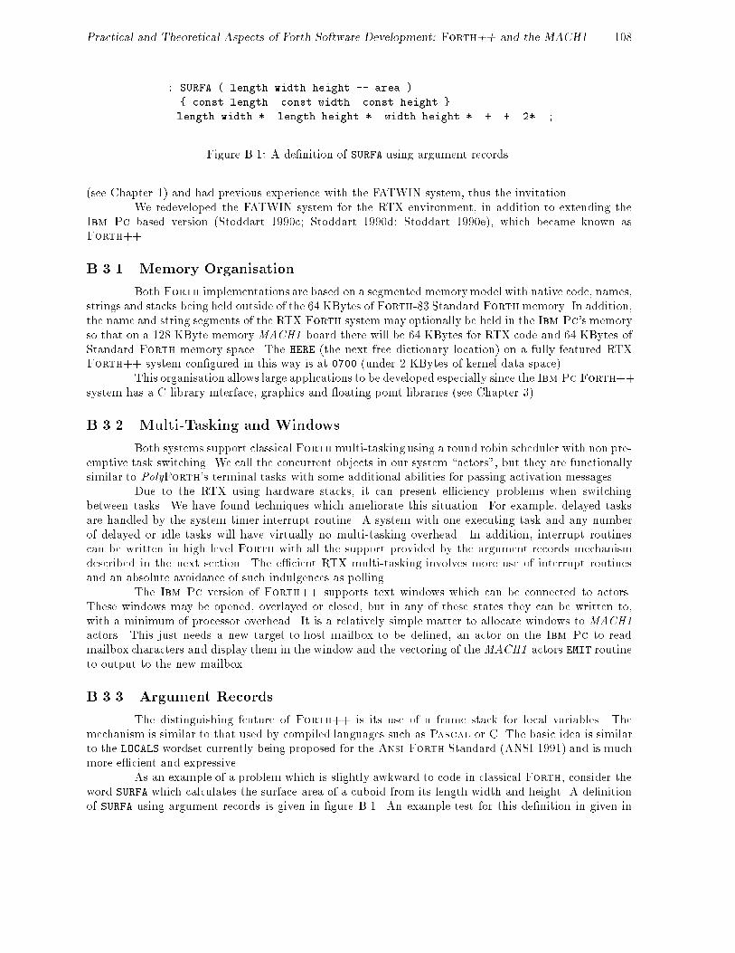
Practical and Theoretical Aspects of Forth Software Development: Forth++ and the MACH1 108
: SURFA ( length width height -- area )
{ const length const width const height }
length width * length height * width height * + + 2* ;
Figure B.1: A de�nition of SURFA using argument records.
(see Chapter 1) and had previous experience with the FATWIN system, thus the invitation.We redeveloped the FATWIN system for the RTX environment, in addition to extending the
Ibm Pc based version (Stoddart 1990c; Stoddart 1990d; Stoddart 1990e), which became known asForth++.
B.3.1 Memory Organisation
Both Forth implementations are based on a segmented memory model with native code, names,strings and stacks being held outside of the 64 KBytes ofForth-83 Standard Forthmemory. In addition,the name and string segments of the RTX Forth system may optionally be held in the Ibm Pc's memoryso that on a 128 KByte memory MACH1 board there will be 64 KBytes for RTX code and 64 KBytes ofStandard Forth memory space. The HERE (the next free dictionary location) on a fully featured RTXForth++ system con�gured in this way is at 0700 (under 2 KBytes of kernel data space).
This organisation allows large applications to be developed especially since the Ibm Pc Forth++system has a C library interface, graphics and oating point libraries (see Chapter 3).
B.3.2 Multi-Tasking and Windows
Both systems support classical Forth multi-tasking using a round robin scheduler with non pre-emptive task switching. We call the concurrent objects in our system \actors", but they are functionallysimilar to PolyForth's terminal tasks with some additional abilities for passing activation messages.
Due to the RTX using hardware stacks, it can present e�ciency problems when switchingbetween tasks. We have found techniques which ameliorate this situation. For example, delayed tasksare handled by the system timer interrupt routine. A system with one executing task and any numberof delayed or idle tasks will have virtually no multi-tasking overhead. In addition, interrupt routinescan be written in high level Forth with all the support provided by the argument records mechanismdescribed in the next section. The e�cient RTX multi-tasking involves more use of interrupt routinesand an absolute avoidance of such indulgences as polling.
The Ibm Pc version of Forth++ supports text windows which can be connected to actors.These windows may be opened, overlayed or closed, but in any of these states they can be written to,with a minimum of processor overhead. It is a relatively simple matter to allocate windows to MACH1actors. This just needs a new target-to-host mailbox to be de�ned, an actor on the Ibm Pc to readmailbox characters and display them in the window and the vectoring of the MACH1 actors EMIT routineto output to the new mailbox.
B.3.3 Argument Records
The distinguishing feature of Forth++ is its use of a frame stack for local variables. Themechanism is similar to that used by compiled languages such as Pascal or C. The basic idea is similarto the LOCALS wordset currently being proposed for the Ansi-Forth Standard (ANSI 1991) and is muchmore e�cient and expressive.
As an example of a problem which is slightly awkward to code in classical Forth, consider theword SURFA which calculates the surface area of a cuboid from its length width and height. A de�nitionof SURFA using argument records is given in �gure B.1. An example test for this de�nition in given in

Practical and Theoretical Aspects of Forth Software Development: Forth++ and the MACH1 109
�gure B.2.
10 20 30 SURFA . Enter 2200 ok
Figure B.2: Testing the SURFA de�nition.
In this de�nition, the immediate word { commences the description of an argument list. Theimmediate de�ning word const is used to create the temporary dictionary entries length, width andheight. The argument list is terminated by the immediate word }, will compile the code required tomove three values from the Forth stack to the frame stack.
When compilation reaches the end of the de�nition, the words length, width and height areremoved from the dictionary and a run time operator is compiled that will remove the current frame fromthe frame stack and perform the exit function.
As a second example, consider a word MAX-OF that �nds the maximum value in a table. Fig-ure B.3 shows a possible de�nition for MAX-OF using argument records.
: MAX-OF ( n.addr n -- max )
{ var table const n -32768 num max }
n 0 DO
val table val max >
IF val table to max THEN
++ table
LOOP
val max
;
Figure B.3: A de�nition of MAX-OF using argument records
The argument record sets up three entries, a pointer to pass through the table of integers(table), a local constant to hold the current value (n) and a local variable to hold the current maximumvalue (max). The local variable is initialised to �32768, the minimum signed 16 bit value.
Within the de�nition, the argument record parameters are preceded by a \method selectionpre�x". The phrase `val table' returns the value of the current table item and the phrase `++ table'will increment the address referenced by table in order to access the next item in the table. The phrase`to max' will store the top of the stack in the local variable max.
: $MATCH ( c.addr1 c.addr2 count -- flag )
{ cvar $1 cvar $2 const n }
TRUE ( if the strings match this will be left )
n 0 DO
val $1 val $2 <>
IF NOT ( switch flag to false ) LEAVE THEN
++ $1 ++ $2
LOOP ;
Figure B.4: A string match function, using argument records.
As a �nal example, �gure B.4 shows a string matching routine. It is a simple task to add

Practical and Theoretical Aspects of Forth Software Development: Forth++ and the MACH1 110
new parameter types. The \method selection" mechanism is based on object oriented programmingtechniques1, thus the same selectors can be used in a polymorphic manner. It is just as simple to addnew method selectors as it is to add new parameter types. See (Stoddart 1984) or (Stoddart 1990b) fora full description of argument records.
B.4 The Multi-Processor Forth Interpreter
B.4.1 The Users View
The user interface is designed so that a user can choose to interact with any of the processorsin the system. It is also possible to de�ne a single command to load and run an application that involvesall of the processors.
We refer to the Ibm Pc as the host system, since it provides terminal and mass storage facilitiesfor the MACH1 which is referred to as the target system.
Interaction
At cold start, the user is interacting with the host system. The command T switches interactionto the MACH1. Where there is more than one MACH1 board, the commands T0, T1 etc. are providedto connect to a particular processor.
To switch interaction from the target board back to the host, the user should press the Alt-Hkey. This will cause the host to exit from the terminal emulation program invoked by T. The targetsystem has a special command `HOST' this causes the host to exit from the terminal emulation programand continue execution from that point. The target also continues its own execution thus allowing a userto invoke tasks on both target and host systems.
We can show how this works with an example. For this system the screen is split into twowindows. Interaction with the target takes place in the one window, whilst interaction with the hosttakes place in the other (larger) window. Whilst connected to the host system a user could enter:
T 1000 2000 DUMP
This connects the user to the target by running the terminal emulation utility T. The rest of the commandline is left to be interpreted when the T utility terminates.
Whilst connected to the target the user could enter:
HOST 0 1000 DUMP
The HOST command causes the host system to terminate its execution of T and to continue execution byinterpreting \1000 2000 DUMP". Meanwhile, the target continues execution by interpreting the text thatfollows HOST, the \0 1000 DUMP". The target's output goes to the �rst window, the host's to the second,both host and target will be dumping 1000 bytes of memory to their respective windows.
Messaging
Sometimes it is useful for a word de�ned on the host to post a message to be interpreted by thetarget. This is achieved with the word T" which has a similar syntax to ." but which queues the followingtext string in a bu�er which will be interpreted by the target when the T command is next invoked.
Suppose we have an application that requires screen 10 to be loaded on both host and targetsystems, screens 11 to 20 to be loaded by the host and screens 21 to 30 by the target. Now suppose thatthe target system is to be set running by the command GO-TARGET (assumed to be de�ned a part of the
1The \method selector" can be viewed as a message, while the \parameter type" is the object class. Thus the phrase`cvar $1' can be interpreted as instigating an instance $1 of class cvar, while the phrase `val $1' can be seen as passingthe message val to the object $1.

Practical and Theoretical Aspects of Forth Software Development: Forth++ and the MACH1 111
target application code) and the host is to be set running with GO-HOST (again assumed to be de�ned aspart of the hosts application code). This can be achieved with the following de�nition:
: RUN
10 LOAD \ Load common screen
11 20 THRU \ Load Host specific application code
T" \ Target will do:
10 LOAD \ Load common screen
21 30 THRU \ Load Target specific application code
HOST \ Release host
GO-TARGET" \ Start target application code
T \ Connect with target
EVAL" GO-HOST" \ Start Host application code
;
Note that EVAL" GO-HOST" simply interprets the text string GO-HOST. This is necessary becausewe are assuming that the word GO-HOST is not de�ned when RUN is compiled, but is de�ned by the hostspeci�c application code on screen 11 to 20.
Viewing code
A �nal important feature of the system is the implementation of a VIEW facility for both Ibm Pcand RTX systems. The phrase VIEW <word> is used to enter the editor in browse mode at the screenwhere <word> is de�ned. The editor also has a search facility to locate text strings. Together with VIEW
this provides a powerful method of reviewing the de�nition and subsequent usage of Forth words.
B.4.2 Implementation Notes
Communication between the Ibm Pc and MACH1 systems takes place via the dual port memoryarea. This contains the MACH1 's disc bu�ers and a number of shared data structures.
The MACH1 sees its keyboard and screen as two \mailboxes" in the dual ported memory.Each mailbox consists of two cells, one of which holds the character in transit, the other providingsynchronisation by holding a \mailbox character available" ag. The MACH1 side of the dual-portinterface is therefore very simple, all the sophistication is on the Ibm Pc side.
The Ibm Pc word T actually performs several tasks. It will accept keyboard input and placesthe key codes into a transfer queue. It also monitors the output mailbox displaying any characters thatappear there. Finally, it monitors a dual port data structure through which the MACH1 posts requestsfor occasional services. These include the \save current system" request, the request to VIEW the sourcecode screen for a given de�nition and the \continue execution" request posted by the HOST word.
A second host actor transfers characters from the character queue to the keyboard mailbox.Another monitors and acts on mass storage requests and another monitors and acts on requests to accessthe Ibm Pc's memory2.
The system, as described, operates in whichever window OPERATOR is currently associated. How-ever, it is easy to provide a dual window system in which interaction with the target takes place in aseparate window. To achieve this, another mailbox with associated access functions must be set up withanother host actor to display the output of the new mailbox in the target window. Having provided thisthe MACH1 's EMIT routine should then be vectored to put the outgoing characters into the new mailbox.
B.5 Code Optimisation
The RTX-2000 family provides many single op-codes which can replace sequences of two or morestandard Forth operations (Harris Semiconductor 1988a). For investigation purposes, we implemented
2This is needed when the name and string segments are being stored in the Ibm Pc's memory rather than on the board.

Practical and Theoretical Aspects of Forth Software Development: Forth++ and the MACH1 112
an optimiser which can recognise every \many to one" code reduction sequence, including those whichinclude high level calls and those de�ned by the user. It uses a tree traversal algorithm and users canadd new branches to the tree to include new op-code sequences for optimisation. The algorithm will alsochange past optimisations if it �nds a better one ahead.
This optimiser is supplied but is not built into the system because the implementation algorithmrequires more space that is likely to be save by optimisation! We have found that a fairly simple optimisercan achieve 90% of the code space and execution time saved by the full optimiser. This mini-optimiser ispermanently loaded and operational by default. Since installing the mini-optimiser, we have not observedany performance degradation.
Theoretically however, an optimiser can interfere with the correct compilation of Forth-83Standard code. For example consider the phrase:
COMPILE SWAP -
If optimisation is on, the sequence `SWAP -' will be optimised and compiled into the single op-code SWAP-.When the compiled code is executed, this is the op-code that will be compiled by COMPILE and not therequired SWAP. To deal with this, the commands OPT and -OPT are provided to turn optimisation on ando�.
One of the most e�ective RTX optimisations is the ability to perform a return instruction inparallel with the last op-code of the routine. Most RTX instructions have a return bit, which is set tocause a return to be executed in parallel with the instruction. Normally the compiler checks whether thelast instruction in a de�nition is an RTX op-code primitive and sets the return bit of the op-code if it is.As an example of where this optimisation is inappropriate consider the de�nition:
: ABS DUP 0< IF NEGATE THEN ;
When compilation reaches the semi-colon, the most recently compiled operation is NEGATE. However, weneed to compile a return op-code rather than set the return bit in the negate op-code. To achieve thisthe de�nition of THEN includes an operation which informs the system that the last op-code compiled cannot be optimised. This is transparent to the user but must be considered if the user is de�ning his owncontrol structure words3.
B.6 Graphics
The Ibm Pc version of Forth++ can support extensive graphics libraries via its interface to Cgraphics library routines (see Chapter 3). In many applications, the speed of the RTX can be a great helpin calculating the form of graphics images. For example, the problem of transforming one graphics imageinto another by producing a series of intermediate images. Another common example is the generationof fractal images.
These applications produce some interesting problems in terms of debugging application codeas the screen that is normally used to observe the progress of our Forth application by means of stackprints, etc., is now given over to display purposes. Forth++ helps with this in two ways:
1. It supports a utility which splits the display screen into two areas, one of which is used by theForth interpreter while the other is used for graphics display.
2. It supports the ability to output text to closed windows. Suppose we are using the dual windowsystem described in section B.4.1, in which the target and host interaction take place in separatewindows. On entering graphics mode the windows are closed but console output is not vectored tothe graphics screen. Therefore, any console output produced during graphics mode will be displayedon exit and the windows are opened again4.
3Due to the way one constructs new control structures in Ansi-Forth this is no longer a consideration.4Due to hardware limitations the contents of the screen are destroyed when entering or exiting graphics mode, thus you
must close windows before entering graphics mode and reopen them on exit.

Practical and Theoretical Aspects of Forth Software Development: Forth++ and the MACH1 113
With the use of network communications via an add on module (see Chapter 2) it is possible toprovide a programming environment, where all text output from the \Graphics" system is passed over thenetwork to a \text" system. Thus allowing the programmer to have the normal programming environmenton one system whilst displaying the graphics screen on the other system. We have programmed such asystem.

114
Appendix C
Mixed Languages Interface: Source
Code
This annex is intended to supplement the \Mixed Languages Interface" chapter (chapter 3). Itgives source listings and some technical comments for the mixed languages interface, as we are currentlyusing it.
The source is split into a number of di�erent �les. These �les are:
CFLOAD.ASM program that loads the Forth++ system and then the C overlay if it is required.
MAKELOAD.BAT batch �le that makes the Forth loader program.
CFINIT.C contains the C initialisation code.
CFORTH.H header �le containing macro de�nitions (push, pop, etc.).
CFORTH1.C an example \user �le". This is the only �le that the user should edit. We have provided anexample module that provides a oating point maths extension, using the C oating point code.
CFASM.ASM holds the code for initialising the C and Forth context switching area, in addition to thecode for performing the context switch.
MAKEOVLS.BAT, MAKEOVLL.BAT make the overlay library, incorporating the user supplied code. Usingthe Small or Large memory models.
C.1 Loader
This is the Microsoft assembler source code for a program that loads in the Forth++ system.It �rst returns as much memory as possible to Ms-Dos. It will then proceed to load in the Forth++segments. For a given segment, the name of the �le to load is obtained by taking the name of the loaderprogram and replacing the .COM by the required segment extensions:
.CDE Code segment
.FOR Forth data segment
.STR String segment
.NAM Name segment
The stack segment is grabbed from memory, but is not initialised by this loader program.After loading in the Forth system it will then load in a C module. Notice that this module is
the last to be loaded. The loader will either take the C �le from the same directory as the Forth++

Practical and Theoretical Aspects of Forth Software Development: Mixed Languages Interface 115
overlays or from a given location. It will then pass control to the C module to allow it to initialise beforeexecuting any of the Forth code. If no C module is required the loader will simply execute the Forthdirectly.
PAGE 60,132 ; Set page size, lines x cols
TITLE 'CForth++ Loader'
comment ;
This file is assembled to produce the Forth system loader. The batch
file MAKELOAD.BAT contains the commands to assemble the file and convert
the object code to .COM format. The file produced by MAKELOAD.BAT is
called FLOADER.TPT. This file is a loader template which is patched and
renamed by the Forth SAVE-SYS routine to produce a customised loader for
a particular Forth system. The distribution files FPP.COM and CFORTH.COM
are examples of Forth loaders produced in this way.
When a loader such as CFORTH.COM is invoked as a DOS command, it detects
its own name (in this case "CFORTH") and loads in the Forth segments
(CFORTH.CDE, CFORTH.FOR, CFORTH.NAM and CFORTH.STR). It also reserves
space for the Forth stack segment. The segment address of each segment
is stored at reserved locations in the Forth code segment.
If a C overlay file was specified at SAVE-SYS time, its name will have
been patched into the loader file and it will be loaded and executed as
an overlay. This overlay will be passed the PSP of the loader, within
which will be the address of the Forth code segment (in an unused FCB
address in the PSP).
If no C overlay file is specified control will be passed directly to the
Forth code segment.
;===================================================================
CFL_TEXT segment byte public 'CODE'
assume cs:CFL_TEXT,ds:CFL_TEXT,es:CFL_TEXT,ss:CFL_TEXT
ORG 100h
entry PROC NEAR
; To enable loader locations to remain at a fixed position known to the
; Forth system, the code starts with a jump.
jmp start
; To allow a common location to place a debug breakpoint this far return
; instruction is placed at location 103 of the loader. Hence when the
; Forth word TRAP is invoked, this far return is executed, thus allowing
; us to use a monitor program to assist in the debugging of our Forth
; code.
dbg PROC FAR
ret
dbg ENDP
; ======================================================================
; Data Area
; ======================================================================
;
; Now we have the data area for the loader. The default values held in
; this section will be altered to suit by Forth's SAVE-SYS command.

Practical and Theoretical Aspects of Forth Software Development: Mixed Languages Interface 116
; Forth Segment sizes (in paragraphs)
csize: dw 1000h ; Code segment
fsize: dw 1000h ; Forth segment
nsize: dw 1000h ; Name segment
$size: dw 800h ; String segment
ssize: dw 1000h ; Stack segment
; Far address to execute Forth
eoff: dw 3 ; Offset within Code segment to start execution
eseg: dw ? ; Will be set when Forth code seg is loaded.
; C Base program name.
;
; This is a counted ASCIIZ sting, with the count including the
; terminating zero
;
; If the count is 0 then no C Base program is loaded and control is
; passed directly to the Forth++ Code segment
;
; If the count is -1 then the ASCIIZ string holds the Complete path name
; Otherwise the file name is added to the end of the default load path
;
cname db 0
db 7fh DUP(?)
; The following equates give addresses in the Forth code segment which
; are used to hold the addresses of other segments.
fsptr equ 06h ; Forth segment pointer
nsptr equ 08h ; Names
$sptr equ 0ah ; Strings
ssptr equ 0ch ; Stack
lsptr equ 0eh ; Loader segment pointer
; Address for Forth to call to re-enter C system. This is initialised
; to point to an error handler by SAVE-SYS and is reset by the C overlay
; initialisation.
roptr equ 10h ; Offset
rsptr equ 12h ; Segment
; Forth++ Segment file name extensions
cfile db "CDE",0 ; Code
ffile db "FOR",0 ; Forth
nfile db "NAM",0 ; Name
$file db "STR",0 ; String
; =====================================================================
; Loader Program
; =====================================================================
;
; Initialise all segments to point to the same (code) segment
start: cld
mov ax,cs
mov ds,ax
mov es,ax

Practical and Theoretical Aspects of Forth Software Development: Mixed Languages Interface 117
mov ss,ax
mov sp,OFFSET stack
; As we use features of DOS that only appeared (documented) in DOS 3.0
; we must make sure that the user is not running an earlier DOS system.
mov bp,OFFSET msg_1 ; Point to the error message
mov ah,30h
int 21h
cmp al,3
jae resize
call abort
; Resize memory back down so that we can grab it
resize: mov bx,64h ; keep enough memory to work in
mov ah,4ah
int 21h ; resize allocated memory
jnc cont
call mem_err
; Find the current program name. This is stored at the end of the
; environment table. The environment table can be a maximum of 32K.
; Each entry is terminated with a 00 byte and the table is terminated
; with a second 00 byte (after an entry terminating 00 byte). The name
; of the currently executing program is then stored as an ASCIIZ string
; 2 bytes on from the end of the environment table.
cont: mov bp,OFFSET msg_3
mov ax,cs:2ch ; Get segment addr of Env. table
mov es,ax
mov cx,8000h ; Max size of Env. table
xor ax,ax
mov di,ax ; Set DI to start of Env. table
scan: or cx,cx
jnz scn1
call abort ; If table too big, Env. error
scn1: repnz scasb ; Find end of entry
scasb ; Is it end of table
jnz scan
add di,2 ; Move DI to start of program name
; The currently executing program name is the full path name of this
; program (eg, C:\FORTH\CFORTH\CFORTH.COM). We copy this name into an
; internal buffer so that we can change it as required.
; This name can be no longer than 7F bytes.
push ds
push es
mov ax,ds
mov es,ax
pop ds
mov si,di
mov di,OFFSET fname
mov cx,7fh
rep movsb
pop ds
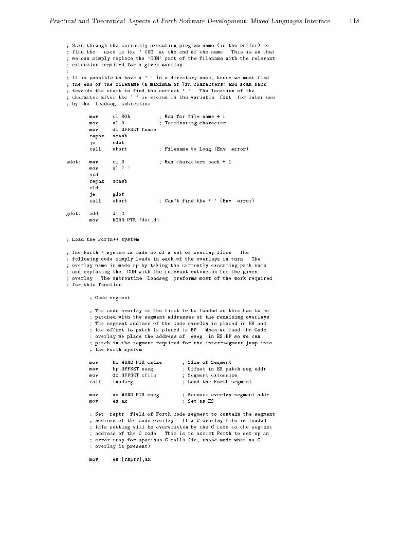
Practical and Theoretical Aspects of Forth Software Development: Mixed Languages Interface 118
; Scan through the currently executing program name (in the buffer) to
; find the . used in the '.COM' at the end of the name. This is so that
; we can simply replace the 'COM' part of the filename with the relevant
; extension required for a given overlay.
;
; It is possible to have a '.' in a directory name, hence we must find
; the end of the filename (a maximum of 7fh characters) and scan back
; towards the start to find the correct '.'. The location of the
; character after the '.' is stored in the variable fdot for later use
; by the loadseg subroutine.
mov cl,80h ; Max for file name + 1
mov al,0 ; Terminating character
mov di,OFFSET fname
repnz scasb
je sdot
call abort ; Filename to long (Env. error)
sdot: mov cl,6 ; Max characters back + 1
mov al,'.'
std
repnz scasb
cld
je gdot
call abort ; Can't find the '.' (Env. error)
gdot: add di,2
mov WORD PTR fdot,di
; Load the Forth++ system.
; The Forth++ system is made up of a set of overlay files. The
; following code simply loads in each of the overlays in turn. The
; overlay name is made up by taking the currently executing path name
; and replacing the .COM with the relevant extension for the given
; overlay. The subroutine loadseg preforms most of the work required
; for this function.
; Code segment
; The code overlay is the first to be loaded as this has to be
; patched with the segment addresses of the remaining overlays.
; The segment address of the code overlay is placed in ES and
; the offset to patch is placed in BP. When we load the Code
; overlay we place the address of eseg in ES:BP so we can
; patch in the segment required for the inter-segment jump into
; the Forth system.
mov bx,WORD PTR csize ; Size of Segment
mov bp,OFFSET eseg ; Offset in ES patch seg addr.
mov dx,OFFSET cfile ; Segment extension
call loadseg ; Load the Forth segment
mov ax,WORD PTR eseg ; Recover overlay segment addr
mov es,ax ; Set as ES
; Set rsptr field of Forth code segment to contain the segment
; address of the code overlay. If a C overlay file is loaded
; this setting will be overwritten by the C code to the segment
; address of the C code. This is to assist Forth to set up an
; error trap for spurious C calls (ie, those made when no C
; overlay is present).
mov es:[rsptr],ax

Practical and Theoretical Aspects of Forth Software Development: Mixed Languages Interface 119
; Forth segment
mov bx,WORD PTR fsize
mov bp,fsptr
mov dx,OFFSET ffile
call loadseg
; Name segment
mov bx,WORD PTR nsize
mov bp,nsptr
mov dx,OFFSET nfile
call loadseg
; String segment
mov bx,WORD PTR $size
mov bp,$sptr
mov dx,OFFSET $file
call loadseg
; Stack segment
; Because the stack segment does not require to be initialised
; we do not have an overlay for it. Here we simply obtain the
; memory required for the stack and patch the code overlay
; directly.
mov bx,WORD PTR ssize
mov ah,48h
int 21h
jnc ssseg
call mem_err
ssseg: mov es:[ssptr],ax
; Load segment
; The lsptr field of the code overlay is set to the segment
; address of the currently execution program. The setup chain
; of the Forth system will then be able to inspect (and execute)
; any text given on the command line after the program name.
mov ax,cs
mov es:[lsptr],ax
; Do we need to load in the C base program?
;
; The byte at cname is the count for an ASCIIZ string holding the name
; of the C overlay file. If this count is 0 (zero) then the C overlay
; is not required, so execution is passed directly to the Forth Code
; overlay.
mov ax,ds
mov es,ax
mov si,OFFSET cname ; Count byte of C overlay name
mov al,[si]
inc si
cmp al,0 ; Is the count zero ?
jne covl ; No => Load the C overlay
jmp DWORD PTR eoff ; Yes => jump to Forth code seg
; The byte at cname did not contain a 0 (zero), hence we must load

Practical and Theoretical Aspects of Forth Software Development: Mixed Languages Interface 120
; (and execute) the C overlay file. If the count byte is -1 the
; following 7fh bytes give the full pathname of the C overlay file.
; However, if the count is not -1, it should be the length of the
; filename (including the terminating zero) for the C overlay. This
; filename will be appended to the current load path, used to load in
; the other overlays.
covl: cmp al,-1
je covl_2
; The count byte indicates the number of characters to add to
; the end of the current load pathname. In order to do this we
; must first find the first character of the file name at the
; end of the most recently loaded overlay (string). This can be
; done by scanning backwards from the . used to indicate the
; overlay type, looking for the \ used to indicate a directory
; name. If the \ is not found within the maximum number of
; characters allowed for a file name (8 + 3) then an Environment
; error is indicated.
mov bp,OFFSET msg_3
push ax
; Find the '\'
mov cx,11
mov di,WORD PTR fdot
mov al,'\'
std
repne scasb
cld
je covl_1
call abort
covl_1: add di,2
; Copy the given filename onto the end of the path
pop cx
mov ch,0
rep movsb
; Load and execute the overlay
jmp cload
; The count byte was -1, so copy the full pathname into the
; internal buffer.
covl_2: mov di,OFFSET fname
mov cx,7fh
rep movsb
cload: ; Load and execute the C overlay file. The name of the file to
; load is in the internal name buffer fname .
; Initialise all seven loadblock fields to 0000h
mov di,OFFSET loadblock
push di
mov cl,7
xor ax,ax
rep stosw
pop di
; Initialise the new loadblock so that the C overlay inherits
; the eseg:eoff values as the first four bytes of its default
; FCB. This is to pass the segment:offset address of the Forth

Practical and Theoretical Aspects of Forth Software Development: Mixed Languages Interface 121
; code overlays entry address to the C system.
mov ax,cs
mov [di+8],ax ; Default FCB segment
mov [di+4],ax ; Command line
mov ax,OFFSET eoff
mov [di+6],ax ; Default FCB holding eseg:eoff
mov ax,80h
mov [di+2],ax ; Command line tail
; Invoke the program (C Overlay file). Note the execution is
; passed to the C overlay file to allow the C initialisation
; code to be executed before the Forth system is invoked. The
; overlay file will invoke the Forth system via the execution
; address passed to it in the default FCB.
mov dx,OFFSET fname
mov bx,di
mov ax,4b00h ; Load and execute an overlay
int 21h
mov bx,cs
mov ss,bx
mov sp,OFFSET stack
jnc execok
call load_err
execok: mov al,0
jmp exit
;===========
; Subroutine: Loadseg -> Load a given Forth++ Segment overlay
;===========
;
; On entry:
; bx => No of paragraphs required for overlay
; es:bp => addr to place segment addr of new overlay
; dx => overlay name
; fdot => addr of first char after the '.' in load file name
loadseg LABEL NEAR
push es
; Grab the memory
mov ah,48h
int 21h
jnc rdseg
call mem_err
; We got it and its seg addr is in ax - patch it into the
; code overlay.
rdseg: mov es:[bp],ax
; set es:bx to the parameter block "loadblock"
push cs
pop es
mov bx,OFFSET loadblock
; Initialise the load parameter block.
mov [bx],ax ; destination segment
mov WORD PTR 2[bx],0 ; load Offset is set to zero
; Copy the overlay extension name over the .COM
mov si,dx
mov di,WORD PTR fdot
mov cl,3

Practical and Theoretical Aspects of Forth Software Development: Mixed Languages Interface 122
rep movsb
; set ds:dx to file name
mov dx,OFFSET fname
; load file as overlay
mov ax,4b03h
int 21h
jnc rdok
call load_err
rdok: pop es
ret
;===========
; Subroutine: Mem_err -> Display a memory error condition and abort
;===========
;
mem_err:mov bp,OFFSET msg_2
;===========
; Subroutine: Abort -> Display an error condition and abort
;===========
;
; BP => Error message to display
; AX => Error code
abort: push bp
push ax
mov bp,OFFSET msg_A ; <CR><LF>Forth++ Load error <
call display
pop dx
pop bp
pop ax
sub ax,3
call hexw ; Address of error
mov al,'/'
call char ; Separator
mov ax,dx
call hexw ; Error code (AX at time of error)
call display ; Error text (for user) '> xxx'
mov bp,OFFSET msg_B ; !<CR><LF><BELL>
call display
mov al,1
;===========
; Subroutine: Exit - Exit back to Dos
;===========
exit: mov ah,4ch ; Exit back to Dos
int 21h
jmp exit
;===========
; Subroutine: Load_err -> Display a load error condition and abort
;===========
;
; fseg:foff => Address of ASCIIZ string holding file name

Practical and Theoretical Aspects of Forth Software Development: Mixed Languages Interface 123
load_err:
mov dx,ax
mov bp,OFFSET msg_A ; <CR><LF>Forth++ Load error <
call display
pop ax
sub ax,3
call hexw ; Execution address
mov al,':' ; Separator char
call char
mov ax,dx ; Error code
call hexw
mov bp,OFFSET msg_5 ; > Can't find:
cmp dx,2
je le_1
cmp dx,3
je le_1
mov bp,OFFSET msg_6 ; > access denied when loading <CR><LF>
cmp dx,5
je le_1
mov bp,OFFSET msg_2 ; > Out of memory
cmp dx,8
je le_2
mov bp,OFFSET msg_3 ; > Environment error
cmp dx,0ah
je le_2
mov bp,OFFSET msg_4 ; > in
le_1: call display ; Display error message
mov bp,OFFSET fname ; Display File name (or err msg)
le_2: call display
mov bp,OFFSET msg_B ; !<CR><LF><BELL>
call display
mov al,1
jmp exit
;===========
; Subroutine: Display -> Display a ASCIIZ string
;===========
;
; BP => addr of ASCIIZ string to be displayed
;
display:cld
push si
mov si,bp
d1: lodsb
cmp al,0
je dr
call char
jmp d1
dr: pop si
ret
;===========
; Subroutine: HexW -> Display a hex word

Practical and Theoretical Aspects of Forth Software Development: Mixed Languages Interface 124
;===========
;
; AX => Word to be displayed as four hex digits
;
hexw: push ax
mov al,ah
call hexb
pop ax
;===========
; Subroutine: HexB -> Display a hex byte
;===========
;
; AL => Byte to be displayed as two hex digits
;
hexb: push ax
mov cl,4 ;*** This is required as MASM (4.0) is
shr al,cl ;*** not able to accept: shr al,4
call hexc
pop ax
;===========
; Subroutine: HexC -> Display a hex character
;===========
;
; AL => Bits 0..3 to be displayed as a single hex digit
;
hexc: and al,0fh
add al,'0'
cmp al,'9'+1
jc char
add al,'A'-('9'+1)
;===========
; Subroutine: Char -> Display a character on the video
;===========
;
; On entry:
; AL => Character to be displayed
;
char: push dx
mov dl,al
mov ah,2
int 21h
pop dx
ret
;======================================================================
; DATA AREA
;======================================================================
; Error messages
msg_A: db 13,10,'Forth++ Load error <',0
msg_B: db ' !',13,10,7,0
; The DOS must be version 3.0 or above
msg_1: db '> Dos 3.0 (or above) required',0
; An out of memory error occurs when a request for memory is denied.

Practical and Theoretical Aspects of Forth Software Development: Mixed Languages Interface 125
msg_2: db '> Out of Memory',0
; An Environment error occurs when:
; 1. The environment table is longer than its maximum 32K.
; 2. The currently executing file name is longer than its max (7F bytes)
; 3. The . can not be found at the end of the file name
; 4. The \ can not be found at the start of the file name
; 5. Returned as an error from the load (4B) function
msg_3: db '> Environment Error',0
; When the load (or load and execute) overlay function (4B) is invoked,
; it may return an error code. The following error messages will be
; displayed dependent on the error code returned.
;
; Out of memory - Insufficient memory to load the overlay
; Environment error - Bad Environment
; Can't find - File does not exist
; Access denied - File access is denied
; in - Any other error condition
msg_4: db '> in ',0
msg_5: db '> Can''t find: ',0
msg_6: db '> Access denied when loading',13,10,0
;=======================================================================
; Variable Space
;=======================================================================
; The offset address of the name that is attempting to be loaded (in
; case of an Can't find error) is stored in an internal variable.
foff dw ?
; The loadblock used to load the overlays (and C base program)
loadblock dw 7 DUP(?)
; A buffer to store the currently executing program name. The name in
; this buffer will be manipulated to form the correct path name for the
; overlay files that make up the CForth++ system.
fdot dw ?
fname db 80h DUP(?)
; Some stack area.
stack dw 160 DUP(?)
entry ENDP
CFL_TEXT ends
end entry
In order to generate the loader program, you should invoke theMAKELOAD batch �le provided. This will produce the (.COM format) loader template FLOADER.TPT. Thisis a simple data �le, loaded into memory (from 0100h) of the current load segment.

Practical and Theoretical Aspects of Forth Software Development: Mixed Languages Interface 126
As this program is less than 2 Kbytes in length, it means that we can store it as a couple ofForth blocks directly. When we need to alter the variables we can simply copy the Forth blocks to therequired �le name to produce the new program loader.
C.2 Making the loader
The MAKELOAD batch �le will process the CFLOAD.ASM �le into the system loader (FLOADER.TPT).The �le is assembled, linked and then converted into the `.COM' format before being renamed FLOADER.TPT
as required by Forth++'s SAVE-SYS command.
rem *** Assemble the loader ***
masm cfload , , , ,
rem *** Link it into a .EXE file ***
link cfload ;
rem *** Now convert it into a .BIN ***
exe2bin cfload.exe
rem *** Copy it to the FLOADER.TPT template ***
copy cfload.bin floader.tpt
rem *** Delete unwanted files ***
del CFLOAD.LST
del CFLOAD.OBJ
del CFLOAD.CRF
del CFLOAD.EXE
del CFLOAD.BIN
C.3 Overlay initialisation
This is the initial C code that is executed immediately after the loader program has loaded inthe C module. It simply calls the assembler code routine FINIT to initialise the Forth interface andthen enters into a tight loop passing control to the Forth system. When control is returned to the Csystem, it pops an integer value o� from the Forth stack and uses it as an index into a jump table of Croutines. The C routine is then executed and control is passed back to the Forth system.
#include "cforth.h"
/**********************************************************************/
/*** ***/
/*** CFORTH1.C Definitions ***/
/*** ***/
/*** The following initialised structures are defined by the ***/
/*** customer code, in the file CFORTH1.C ***/
/*** ***/
/*** ***/
/*
* jmptbl[] is a table that contains functions that can be invoked from
* the Forth system. A function number is used as an index into the
* table.
*/
extern TBL jmptbl[];
/*
* The function startup() is invoked after initialisation of the C

Practical and Theoretical Aspects of Forth Software Development: Mixed Languages Interface 127
* system to allow the customer code to perform any initialisation that
* it may require.
*/
extern void startup(void);
/*** ***/
/*** End of CFORTH.C definitions ***/
/*** ***/
/**********************************************************************/
/**********************************************************************/
/*** ***/
/*** Forth Interface ***/
/*** ***/
/*** The following code is for the C Main function. This code is ***/
/*** the interface between C system and the Forth system. It ***/
/*** also provides the calling mechanism to allow the Forth system ***/
/*** to invoke the C functions given in the jump table. The ***/
/*** external functions (FINIT and FORTH) can be found in the MASM ***/
/*** assembly source code file CFASM.ASM. ***/
/*** ***/
/*** This code should NOT be altered unless you are sure about it! ***/
/*** ***/
/**********************************************************************/
/*
* Declare the external values. The function FINIT() is called to
* initialise the Forth++ system. It will initialise the context
* switching area. The function FORTH() will save the C environment,
* build the Forth environment and then continue execution of the Forth
* system. When the Forth system wants to invoke a C function it will
* return to FORTH(). FORTH() will then swap execution environments and
* return execution to the C system. The Forth Stack Pointer is updated
* on entry/exit of the Forth system.
*/
/*
* Under Zortech C++ we must declare these functions as having C type
* linking. Hence the next two lines would be:
*
* extern "C" { void FINIT(void); }
* extern "C" { void FORTH(void); }
*
* Note: This is only required for C++, the Zortech C compiler will
* error when given this code.
*/
extern void far FINIT(void);
extern void far FORTH(void);
main(void)
{
/* Invoke the Forth initialisation code */
FINIT();
/* Invoke customer C start up code */
startup();
/* Execute Forth and interpret any C calls */
{
unsigned int i;
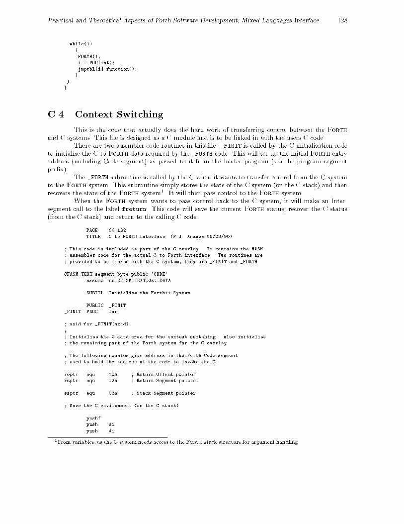
Practical and Theoretical Aspects of Forth Software Development: Mixed Languages Interface 128
while(1)
{
FORTH();
i = POP(int);
jmptbl[i].function();
}
}
}
C.4 Context Switching
This is the code that actually does the hard work of transferring control between the Forthand C systems. This �le is designed as a C module and is to be linked in with the users C code.
There are two assembler code routines in this �le. _FINIT is called by the C initialisation codeto initialise the C to Forth data required by the _FORTH code. This will set up the initial Forth entryaddress (including Code segment) as passed to it from the loader program (via the program segmentpre�x).
The _FORTH subroutine is called by the C when it wants to transfer control from the C systemto the Forth system. This subroutine simply stores the state of the C system (on the C stack) and thenrecovers the state of the Forth system1. It will then pass control to the Forth system.
When the Forth system wants to pass control back to the C system, it will make an Inter-segment call to the label freturn. This code will save the current Forth status, recover the C status(from the C stack) and return to the calling C code.
PAGE 66,132
TITLE C to FORTH Interface (P.J. Knaggs 08/08/90)
; This code is included as part of the C overlay. It contains the MASM
; assembler code for the actual C to Forth interface. Two routines are
; provided to be linked with the C system, they are _FINIT and _FORTH.
CFASM_TEXT segment byte public 'CODE'
assume cs:CFASM_TEXT,ds:_DATA
SUBTTL Initialise the Forth++ System
PUBLIC _FINIT
_FINIT PROC far
; void far _FINIT(void)
;
; Initialise the C data area for the context switching. Also initialise
; the remaining part of the Forth system for the C overlay.
; The following equates give address in the Forth Code segment
; used to hold the address of the code to invoke the C
roptr equ 10h ; Return Offset pointer
rsptr equ 12h ; Return Segment pointer
ssptr equ 0ch ; Stack Segment pointer
; Save the C environment (on the C stack)
pushf
push si
push di
1From variables, as the C system needs access to the Forth stack structure for argument handling

Practical and Theoretical Aspects of Forth Software Development: Mixed Languages Interface 129
push bp
push es
push ds
mov ax,_DATA
mov ds,ax
; Set Direction Flag to increment
cld
; Extract the execution seg & offset of the Forth system from locations
; 5ch and 5eh of the PSP, where they will have been deposited by the
; Forth system loader. Locations 5c and 5e are safe to use as they are
; in redundant PSP locations (actually a file control block).
mov ah,62h
int 21h
mov es,bx
; Store the execution seg & offset in eseg & eoff
mov ax,WORD PTR es:5ch ; Execution offset
mov eoff,ax
mov ax,WORD PTR es:5eh ; Execution (Code) Segment
mov eseg,ax
mov es,ax
; We can now place the C execution vector into the Forth code segment.
; This is the address of the code that the Forth system is to execute
; when it transfers control back to the C system. This is set to an
; error reporter by SAVE-SYS, but we now replace it to point to freturn.
mov ax,SEG freturn
mov es:[rsptr],ax ; Return Seg Pointer
mov ax,OFFSET freturn
mov es:[roptr],ax ; Return Offset Ptr
; We must set up the Forth stack (segment and offset) so that on the
; first execution of _FORTH the stack is at a sensible location.
; Thereafter it will be looked after by the Forth system.
mov ax,es:[ssptr]
mov WORD PTR sseg,ax
mov ax,4
mov WORD PTR soff,ax
; Recover the C environment from the stack
pop ds
pop es
pop bp
pop di
pop si
popf
ret
_FINIT ENDP
SUBTTL Switch context between C and Forth and back again
PUBLIC _FORTH
_FORTH PROC far

Practical and Theoretical Aspects of Forth Software Development: Mixed Languages Interface 130
; void FORTH(void) - Enter into the forth system
;
; When the C system has completed its task it will transfer control
; to the Forth system by executing this code. When the Forth system
; wants to re-enter the C system it will invoke the code at freturn.
;
; The C environment is stored on the C stack before the SS:SP address
; is stored in cseg:coff. All registers not saved can be discarded or
; recovered by the program.
; Save the C environment
pushf
push si
push di
push bp
push es
push ds
; Save the C stack
mov ax,_DATA
mov ds,ax
mov cseg,ss
mov coff,sp
; Read Forth stack (from __FSP)
mov sp,soff
mov ss,sseg
; Set up for re-entry to Forth with a far return
push eseg
push eoff
; Restore Forth environment
; Forth++ uses the following registers:
; SI, BP, BX, CS, DS, SS and SP
;
; We are changing the stack pointer so we must generate
; the new values of SS:SP (stored in the variable __FSP)
;
; The CS:IP value will be set when we return to the forth
; system. The values are stored in eseg:eoff
;
; The remaining registers are stored in an environment buffer.
; They can not be stored on the Forth stack as the C code
; requires access to the Forth stack for argument passing, thus
; these values are stored in this environment buffer fbuf .
mov si,fiip
mov bp,frsp
mov bx,fubp
mov ds,fds
; Clear direction flag (required in Forth inner interpreter)
cld
; Execute the Forth system
ret

Practical and Theoretical Aspects of Forth Software Development: Mixed Languages Interface 131
; Forth to C
;
; When Forth is ready to invoke a C function, it will make an inter-
; segment call to the following code. This will return to the C code
; which will, in turn, pop an integer value from the Forth stack and
; execute the corresponding jump table entry.
freturn label near
; Set the data segment to access interface data
push ds
mov ax,_DATA
mov ds,ax
; Save Forth's environment
; As the C system requires access to the Forth stack (to get the
; function request number and any other argument passing) we
; can't store the systems state on the Forth stack. Thus we
; must store it in the "environment buffer", fbuf .
mov fiip,si
mov frsp,bp
mov fubp,bx
pop fds
; Save Forth's re-entry point
pop eoff
pop eseg
; Save Forth's stack (in __FSP)
mov sseg,ss
mov soff,sp
; Recover the C environment
; Recover the C stack
mov ss,cseg
mov sp,coff
; Recover the C registers
pop ds
pop es
pop bp
pop di
pop si
popf
; Return to the C system
ret
_FORTH ENDP
CFASM_TEXT ends
SUBTTL Data Area
_DATA segment word public 'DATA'
; This is the Data Area required by the _FORTH function.

Practical and Theoretical Aspects of Forth Software Development: Mixed Languages Interface 132
; The Following locations are the store for the Forth++ Environment
fbuf label word
fiip dw ? ; Inner Interpreter ptr
frsp dw ? ; Return Stack ptr
fubp dw ? ; User Base ptr
fds dw ? ; Data Segment
; Space to hold the C stack pointer
coff dw ?
cseg dw ?
; Space to hold the Forth Stack Pointer.
PUBLIC __FSP ; Used by C to manipulate Forth Stack
__FSP label dword
soff dw ?
sseg dw ?
; Space to hold the Execution Address of the Forth system
eoff dw ?
eseg dw ?
_DATA ends
end
This module is merged with the CFINIT.C module to form a library. This makes the linkingprocess much simpler. In order to build this library one must �rst obtain the \object code" for the twomodules. To assemble the CFASM.ASM �le one would give the command:
MASM CFASM, CFASM, NUL, NUL /mx
While the CFINIT.C modules needs to be compiled:
TCC -c -ml -G CFINIT
Here we are compiling the C module with Borland's \Turbo C" compiler. The `-c' indicates that wewant to compile the �le. The `-G' instructs the compiler to optimise the code for speed rather than size.Finally the `-ml' option instructs the compiler to use the \Large" memory model.
We are now in a position to make the library. This we do by giving the command:
TLIB CFORTH /C +CFASM +CFINIT
In this instruction we are asking the system to generate a library namedCFORTH.LIB which is case sensitive with regard to the public labels. This library consists of mergingthe two object code �les CFASM.OBJ and CFINIT.OBJ that we have just produced.
C.5 Stack access
C access to the Forth stack is provided via a set of type independent macros. The header �leCFORTH.H de�nes these macros, it should be included into the users C code.
/*******************************************************************/
/*** ***/
/*** CFORTH.H ***/
/*** ***/

Practical and Theoretical Aspects of Forth Software Development: Mixed Languages Interface 133
/*** The following lines of code make up the file CFORTH.H. ***/
/*** ***/
/*
* entry() is a macro definition designed to help in the setting up of
* the jump table. To use this macro you must be defining the jump
* table, simply type:
*
* entry(func)
*
* where func is the name of the code required for the given entry.
*/
#define entry(func) { func }
/*** ***
*** The following definitions set up the types required by the ***
*** jump table. ***
*** ***/
/*
* The type PFI is defined to be a Pointer to an Function returning an
* Integer.
*/
typedef int (*PFI)();
/*
* The table entry structure is defined to be of type PFI.
*/
#define TBL struct tabentry
TBL { PFI function; };
/****************************************************************/
/* */
/* Stack Manipulations */
/* */
/* The following functions are defined to Manipulate the Forth */
/* systems stack. Items can be popped off the stack and pushed */
/* onto it. All communication between the C system and the */
/* Forth system should be conducted via these functions. */
/* */
/****************************************************************/
/*
* The Forth Stack Pointer is stored as a far pointer to a void.
* This is stored in the CFASM module for access by the assembly
* code.
*/
extern void far * _FSP;
/*
* The DROP(type) macro is defined to drop an item of the given type
* from the Forth stack.
*/
#define DROP(type) (type far *)_FSP += 1
/*
* The macro INDEX(type,n) is used to return the n-th stack item of the
* given type. Hence INDEX(int,0) will return the TOP int on the stack,
* while INDEX(double,1) will return the second double on the stack.
*/

Practical and Theoretical Aspects of Forth Software Development: Mixed Languages Interface 134
#define INDEX(type,n) *( (type far *)_FSP+n )
/*
* The macro IINDEX(type,offset) is used in the same manner as the
* INDEX() macro except that the offset value is in stack cells and has
* no regard to type size.
*/
#define IINDEX(type,n) *( (type far *) ( (int far *)_FSP+n ) )
/*
* The macro POP(type) is used to POP an item of the given type from the
* Forth stack.
*/
#define POP(type) *(type far *)_FSP; (type far *)_FSP += 1
/*
* The PUSH(type,val) macro is used to PUSH a given value (val) of the
* given type onto the Forth stack.
*/
#define PUSH(type,n) (type far *)_FSP -= 1; *(type far *)_FSP = n
/*
* Note:
* The macros POP and PUSH should have been defined as follows:
*
* #define POP(type) *(type far *)(_FSP++);
* #define PUSH(type,n) *(type far *)(--_FSP) = n;
*
* However Zortech C was the only system that could handle this complex
* a definition. For both Microsoft and Borland the definition has to
* be split as above.
*/
/*** ***/
/*** End of CFORTH.H ***/
/*** ***/
/**********************************************************************/
C.6 User code
The user places his code in a separate \user" module. The �leCFORTH1.C is an example user module. In this example module, we provide a oating point mathssystem using the C oating point code rather than developing our own.
The user must provide the `jmptbl' jump table. The routine `setup' must also be provided toinitialise any user code.
The user can write any C code they like in this �le. The functions that they want to be accessiblefrom Forth must be given in the jump table.
A function that is to be invoked from Forth must not have any arguments and must not returna value. All argument passing should be performed by means of the macros provided in CFORTH.H. Thesemacros actually manipulate the Forth stack directly (as a C data structure).
/**********************************************************************/
/*** ***/
/*** CFORTH Header ***/
/*** ***/
/*** You must include the CFORTH.H header file in order to define ***/

Practical and Theoretical Aspects of Forth Software Development: Mixed Languages Interface 135
/*** the macros used to manipulate the Forth stack. It also ***/
/*** defines the structure of the jump table. ***/
/*** ***/
/**********************************************************************/
#include "cforth.h"
#include <stdio.h>
#include <stdlib.h>
#include <math.h>
/**********************************************************************/
/*** ***/
/*** User Functions: ***/
/*** ***/
/*** The following are the C functions which are to be called by ***/
/*** Forth. After they have been defined the functions will be ***/
/*** placed in a jump table. These functions do not pass ***/
/*** parameters in normal C fashion and must have the prototype: ***/
/*** ***/
/*** int func(void) ***/
/*** ***/
/*** Ie, default functions taking no arguments. Actually the ***/
/*** functions pass their arguments via the Forth stack, which ***/
/*** appears to the C program as a data structure. Forth stack ***/
/*** arguments are accessed with PUSH and POP macros. ***/
/*** ***/
/*** To pop a value use: x = POP(type); eg, x = POP(int); ***/
/*** To push a value use: PUSH(type,x); eg, PUSH(int,-1); ***/
/*** ***/
/**********************************************************************/
/*
* Declare variables to hold forth segment and offset. A Forth call
* will set fseg to the Forth memory space segment address. fseg and
* ofs are used when a 16 bit Forth memory address is passed to a C
* function.
*/
unsigned fseg, ofs;
/*** ***
*** Provide floating point support. ***
*** ***/
/*
* declare floating point stack and stack pointer.
*/
double fs[100], *fsp;
int base_pointer;
/*** ***
*** Set up initial values for floating point stack pointer and ***
*** floating point base pointer. A margin of 5 elements is ***
*** allowed to cater for stack underflow, which Forth will check ***
*** for after interpreting each command line. ***
*** ***/
call_finit() { fsp=fs+5; base_pointer = 5; }
/*** ***
*** The following code is invoked by the Forth system to set the ***
*** fseg variable to the Forth data segment. Thus allowing far ***
*** addresses to be calculated (with MK_FP). ***
*** ***/

Practical and Theoretical Aspects of Forth Software Development: Mixed Languages Interface 136
setfseg() { fseg = POP(int); }
/**********************************************************************
*** ***
*** Floating point functions ***
*** ***
**********************************************************************/
call_fdiv() { *(fsp-1) = *(fsp-1) / *fsp; fsp-- ; }
call_float() { ++fsp; *fsp = (double) POP(int); }
call_fminus() { *(fsp-1) = *(fsp-1) - *fsp; fsp-- ; }
call_fmult() { *(fsp-1) = *(fsp-1) * *fsp; fsp-- ; }
call_fplus() { *(fsp-1) = *(fsp-1) + *fsp; fsp-- ; }
call_int() {
int n;
n = (int) *fsp; fsp--; PUSH(int,n); }
fppfrom() { PUSH(float,*fsp); fsp--; }
tofpp() { ++fsp; *fsp = POP(float); }
fdup() { ++fsp; *fsp = *(fsp-1); }
fdrop() { --fsp; }
fswap() {
double temp;
temp = *fsp; *fsp = *(fsp-1); *(fsp-1) = temp; }
fover() { ++fsp; *fsp = *(fsp-2); }
frot() {
double temp;
temp = *fsp; *fsp = *(fsp-2); *(fsp-2) = *(fsp-1); *(fsp-1) = temp; }
setstackpointer() { fsp = fs + POP(int); }
fetchstackpointer() { PUSH(int,fsp-fs); }
setbasepointer() { base_pointer = POP(int); }
fetchbasepointer() { PUSH(int,base_pointer); }
framefetch() {
int index;
index = POP(int); ++fsp; *fsp = fs[index+base_pointer+1]; }
framestore() {
int index;
index = POP(int); fs[index+base_pointer+1] = *fsp; --fsp; }
d_to_f() { ++fsp; *fsp = POP(long); }
f_to_d() { PUSH(long,*fsp); --fsp; }
fless() {
if (*(fsp-1) < *fsp) { PUSH(int,-1); } else { PUSH(int,0); }
--fsp; --fsp; }

Practical and Theoretical Aspects of Forth Software Development: Mixed Languages Interface 137
fgreater() {
if (*(fsp-1) > *fsp) { PUSH(int,-1); } else { PUSH(int,0); }
--fsp; --fsp; }
fequal() {
if (*(fsp-1) == *fsp) { PUSH(int,-1); } else { PUSH(int,0); }
--fsp; --fsp; }
f0greater() {
if (*fsp > 0) { PUSH(int,-1); } else { PUSH(int,0); }
--fsp; }
f0less() {
if (*fsp < 0) { PUSH(int,-1); } else { PUSH(int,0); }
--fsp; }
f0equal() {
if (*fsp == 0) { PUSH(int,-1); } else { PUSH(int,0); }
--fsp; }
fdepth() { PUSH(int, fsp-fs-base_pointer); }
call_acos() { *fsp = acos(*fsp); }
call_asin() { *fsp = asin(*fsp); }
call_atan2() { *(fsp-1) = atan2(*fsp,*(fsp-1)); --fsp; }
call_cos() { *fsp = cos(*fsp); }
call_sin() { *fsp = sin(*fsp); }
call_cosh() { *fsp = cosh(*fsp); }
call_sinh() { *fsp = sinh(*fsp); }
sincos() {
double temp;
temp = *fsp; *fsp++ = sin(temp); *fsp = cos(temp); }
call_exp() { *fsp = exp(*fsp); }
call_fabs() { *fsp = fabs(*fsp); }
call_floor() { *fsp = floor(*fsp); }
call_frexp() {
int n;
*fsp = frexp(*fsp,&n); PUSH(int,n); }
call_ldexp() {
int exp;
exp = POP(int); *fsp = ldexp(*fsp,exp); }
call_log() { *fsp = log(*fsp); }
call_log10() { *fsp = log10(*fsp); }
call_modf() { ++fsp; *fsp = modf(*fsp,fsp-1); }
call_pow() { *(fsp-1) = pow(*(fsp-1),*fsp); --fsp; }
call_pow10() { *fsp = pow10(*fsp); }
call_sqrt() { *fsp = sqrt(*fsp); }
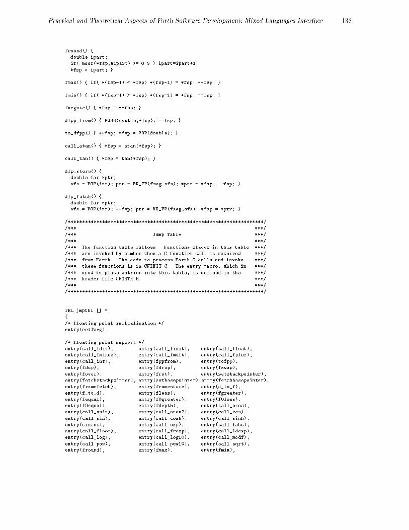
Practical and Theoretical Aspects of Forth Software Development: Mixed Languages Interface 138
fround() {
double ipart;
if( modf(*fsp,&ipart) >= 0.5 ) ipart=ipart+1;
*fsp = ipart; }
fmax() { if( *(fsp-1) < *fsp) *(fsp-1) = *fsp; --fsp; }
fmin() { if( *(fsp-1) > *fsp) *(fsp-1) = *fsp; --fsp; }
fnegate() { *fsp = -*fsp; }
dfpp_from() { PUSH(double,*fsp); --fsp; }
to_dfpp() { ++fsp; *fsp = POP(double); }
call_atan() { *fsp = atan(*fsp); }
call_tan() { *fsp = tan(*fsp); }
dfp_store() {
double far *ptr;
ofs = POP(int); ptr = MK_FP(fseg,ofs); *ptr = *fsp; --fsp; }
dfp_fetch() {
double far *ptr;
ofs = POP(int); ++fsp; ptr = MK_FP(fseg,ofs); *fsp = *ptr; }
/*********************************************************************/
/*** ***/
/*** Jump Table ***/
/*** ***/
/*** The function table follows. Functions placed in this table ***/
/*** are invoked by number when a C function call is received ***/
/*** from Forth. The code to process Forth C calls and invoke ***/
/*** these functions is in CFINIT.C. The entry macro, which in ***/
/*** used to place entries into this table, is defined in the ***/
/*** header file CFORTH.H ***/
/*** ***/
/*********************************************************************/
TBL jmptbl [] =
{
/* floating point initialisation */
entry(setfseg),
/* floating point support */
entry(call_fdiv), entry(call_finit), entry(call_float),
entry(call_fminus), entry(call_fmult), entry(call_fplus),
entry(call_int), entry(fppfrom), entry(tofpp),
entry(fdup), entry(fdrop), entry(fswap),
entry(fover), entry(frot), entry(setstackpointer),
entry(fetchstackpointer), entry(setbasepointer),entry(fetchbasepointer),
entry(framefetch), entry(framestore), entry(d_to_f),
entry(f_to_d), entry(fless), entry(fgreater),
entry(fequal), entry(f0greater), entry(f0less),
entry(f0equal), entry(fdepth), entry(call_acos),
entry(call_asin), entry(call_atan2), entry(call_cos),
entry(call_sin), entry(call_cosh), entry(call_sinh),
entry(sincos), entry(call_exp), entry(call_fabs),
entry(call_floor), entry(call_frexp), entry(call_ldexp),
entry(call_log), entry(call_log10), entry(call_modf),
entry(call_pow), entry(call_pow10), entry(call_sqrt),
entry(fround), entry(fmax), entry(fmin),

Practical and Theoretical Aspects of Forth Software Development: Mixed Languages Interface 139
entry(fnegate), entry(dfpp_from), entry(to_dfpp),
entry(call_atan), entry(call_tan), entry(dfp_store),
entry(dfp_fetch)
};
/**********************************************************************/
/*** ***/
/*** Start Up ***/
/*** ***/
/*** The following code is executed as part of the initialisation ***/
/*** sequence. It should perform any initialisation required by ***/
/*** the C code. ***/
/*** ***/
/**********************************************************************/
void startup()
{
call_finit();
}
C.7 Making the C Overlay
To make the C overlay, one must �rst compile the user code CFORTH1.C with the command:
TCC -c -ml -G -d CFORTH1
The `-d' option is instructing the compiler to merge any duplicate strings it may �nd.Having compiled the user code successfully we are able to link the �le with the CFORTH.LIB
library that we produced earlier:
TLINK /c C0L CFORTH1, CFORTH.OVL, CFORTH, CFORTH CL
In this command, we are linking the user code CFORTH1.OBJ with the standard pre�x code C0L.OBJ, thelibrary CFORTH.LIB and the standard C library CL.LIB. We have instructed the system to produce theoverlay �le CFORTH1.OVL. In addition to this, the command will also produce a map �le CFORTH.MAP.Finally the `/c' option is given to instruct the system that all label names are case sensitive.
As Ms-Dos does not provide a \make" facility, we provide two batch �les that will compile theC/Forth interface library and the users code into the C overlay that would be loaded by the CForth++system. The MAKEOVLL.BAT �le uses the Large memory model:
rem *** Make the library ***
masm cfasm cfasm nul nul /mx
tcc -c -ml -G -d -r- cfinit
tlib cforth /C -+cfasm -+cfinit
rem *** Compile the overlay CFORTH1.C ***
tcc -c -ml -G -d cforth1
rem *** Link it with the Large libraries ***
tlink /x \tc\lib\c0l cforth1, cforth1.ovl, cforth, cforth \tc\lib\mathl
\tc\lib\emu \tc\lib\graphics \tc\lib\cl
It is also possible to use the Small memory model. For this one should use the MAKEOVLS.BAT
batch �le. This should be used if at all possible, as the C system requires less overhead for a small model,rather than the large memory model.
rem *** Make the library ***
masm cfasm cfasm nul nul /mx

Practical and Theoretical Aspects of Forth Software Development: Mixed Languages Interface 140
tcc -c -ms -G -d -r- cfinit
tlib cforth /C -+cfasm -+cfinit
rem *** Compile the overlay CFORTH1.C ***
tcc -c -ms -G -d cforth1
rem *** Link with the Small libraries ***
tlink /x \tc\lib\c0s cforth1, cforth1.ovl, cforth, cforth \tc\lib\maths
\tc\lib\emu \tc\lib\graphics \tc\lib\cs
This batch �le di�ers from the previous only in that it compiles both the CFINIT module and the CFORTH1user module using the small memory model. It also links the system together with the standard smalllibraries (c0s, maths and cs as opposed to c0l, mathl and cl).