practical implementation of spatial...
TRANSCRIPT
IEEE TRANSACTIONS ON VEHICULAR TECHNOLOGY, VOL. 62, NO. 9, NOVEMBER 2013 4511
Practical Implementation of Spatial ModulationNikola Serafimovski, Abdelhamid Younis, Raed Mesleh, Senior Member, IEEE, P. Chambers,
Marco Di Renzo, Member, IEEE, Cheng-Xiang Wang, Senior Member, IEEE,Peter M. Grant, Fellow, IEEE, Mark A. Beach, and Harald Haas, Member, IEEE
Abstract—In this paper, we seek to characterize the perfor-mance of spatial modulation (SM) and spatial multiplexing (SMX)with an experimental testbed. Two National Instruments (NI)PXIe devices are used for the system testing: one for the transmit-ter and one for the receiver. The digital signal processing (DSP)that formats the information data in preparation for transmissionis described, along with the DSP that recovers the informationdata. In addition, the hardware limitations of the system are alsoanalyzed. The average bit-error ratio (ABER) of the system isvalidated through both theoretical analysis and simulation resultsfor SM and SMX under the line-of-sight (LoS) channel conditions.
Index Terms—Experimental results, multiple-input multiple-output (MIMO) systems, spatial modulation (SM), spatial multi-plexing (SMX), wireless testbed.
I. INTRODUCTION
MULTIPLE-INPUT multiple-output (MIMO) systems of-fer a significant increase in spectral efficiency in com-
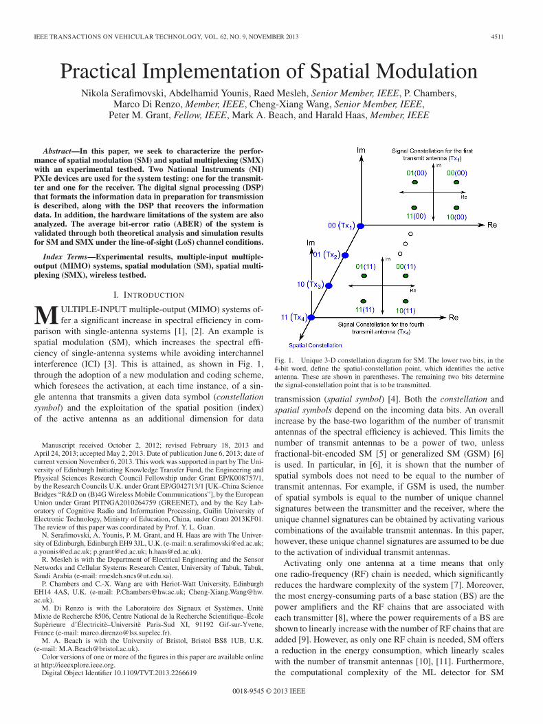
parison with single-antenna systems [1], [2]. An example isspatial modulation (SM), which increases the spectral effi-ciency of single-antenna systems while avoiding interchannelinterference (ICI) [3]. This is attained, as shown in Fig. 1,through the adoption of a new modulation and coding scheme,which foresees the activation, at each time instance, of a sin-gle antenna that transmits a given data symbol (constellationsymbol) and the exploitation of the spatial position (index)of the active antenna as an additional dimension for data
Manuscript received October 2, 2012; revised February 18, 2013 andApril 24, 2013; accepted May 2, 2013. Date of publication June 6, 2013; date ofcurrent version November 6, 2013. This work was supported in part by The Uni-versity of Edinburgh Initiating Knowledge Transfer Fund, the Engineering andPhysical Sciences Research Council Fellowship under Grant EP/K008757/1,by the Research Councils U.K. under Grant EP/G042713/1 [UK–China ScienceBridges “R&D on (B)4G Wireless Mobile Communications”], by the EuropeanUnion under Grant PITNGA2010264759 (GREENET), and by the Key Lab-oratory of Cognitive Radio and Information Processing, Guilin University ofElectronic Technology, Ministry of Education, China, under Grant 2013KF01.The review of this paper was coordinated by Prof. Y. L. Guan.
N. Serafimovski, A. Younis, P. M. Grant, and H. Haas are with The Univer-sity of Edinburgh, Edinburgh EH9 3JL, U.K. (e-mail: [email protected];[email protected]; [email protected]; [email protected]).
R. Mesleh is with the Department of Electrical Engineering and the SensorNetworks and Cellular Systems Research Center, University of Tabuk, Tabuk,Saudi Arabia (e-mail: [email protected]).
P. Chambers and C.-X. Wang are with Heriot-Watt University, EdinburghEH14 4AS, U.K. (e-mail: [email protected]; [email protected]).
M. Di Renzo is with the Laboratoire des Signaux et Systèmes, UnitèMixte de Recherche 8506, Centre National de la Recherche Scientifique–ÉcoleSupèrieure d’Électricitè–Universitè Paris-Sud XI, 91192 Gif-sur-Yvette,France (e-mail: [email protected]).
M. A. Beach is with the University of Bristol, Bristol BS8 1UB, U.K.(e-mail: [email protected]).
Color versions of one or more of the figures in this paper are available onlineat http://ieeexplore.ieee.org.
Digital Object Identifier 10.1109/TVT.2013.2266619
Fig. 1. Unique 3-D constellation diagram for SM. The lower two bits, in the4-bit word, define the spatial-constellation point, which identifies the activeantenna. These are shown in parentheses. The remaining two bits determinethe signal-constellation point that is to be transmitted.
transmission (spatial symbol) [4]. Both the constellation andspatial symbols depend on the incoming data bits. An overallincrease by the base-two logarithm of the number of transmitantennas of the spectral efficiency is achieved. This limits thenumber of transmit antennas to be a power of two, unlessfractional-bit-encoded SM [5] or generalized SM (GSM) [6]is used. In particular, in [6], it is shown that the number ofspatial symbols does not need to be equal to the number oftransmit antennas. For example, if GSM is used, the numberof spatial symbols is equal to the number of unique channelsignatures between the transmitter and the receiver, where theunique channel signatures can be obtained by activating variouscombinations of the available transmit antennas. In this paper,however, these unique channel signatures are assumed to be dueto the activation of individual transmit antennas.
Activating only one antenna at a time means that onlyone radio-frequency (RF) chain is needed, which significantlyreduces the hardware complexity of the system [7]. Moreover,the most energy-consuming parts of a base station (BS) are thepower amplifiers and the RF chains that are associated witheach transmitter [8], where the power requirements of a BS areshown to linearly increase with the number of RF chains that areadded [9]. However, as only one RF chain is needed, SM offersa reduction in the energy consumption, which linearly scaleswith the number of transmit antennas [10], [11]. Furthermore,the computational complexity of the ML detector for SM
0018-9545 © 2013 IEEE

4512 IEEE TRANSACTIONS ON VEHICULAR TECHNOLOGY, VOL. 62, NO. 9, NOVEMBER 2013
Fig. 2. Block sequence of the main steps in the experiment from the genera-tion of the binary data to its recovery.
[SM-maximum likelihood (ML)] is equal to the complexityof single-input multiple-output (SIMO) systems [12], i.e., thecomplexity of SM-ML depends only on the spectral efficiencyand the number of receive antennas and does not dependon the number of transmit antennas. Moreover, in [13]–[15],the complexity of SM is further reduced by using the spheredecoder (SD).
Several papers that seek to understand and improve the per-formance of SM in various scenarios are available in literature.In [16] and [17], the average bit-error ratio (ABER) perfor-mance of SM is improved by introducing trellis coding on thetransmitting antennas. The optimal detector is derived with andwithout channel state information at the receiver in [12], [18],and [19]. The ABER performance is given when consideringchannel estimation errors in [20]–[22]. The optimal powerallocation for the case of two transmit antennas and one receiveantenna system is given in closed form in [23], and the ABERperformance of SM in correlated fading channels is consideredin [24]. In [25] and [26], spectral efficiency and diversity gainsare obtained by combining SM with space–time block codes(STBC-SM). Applying SM to relaying systems is also shownto result in significant signal-to-noise-ratio (SNR) gains whencompared with noncooperative decode and forward techniques[27]. In [28], the overall power performance of a BS employ-ing SM is studied. More recently, a comprehensive analyticalframework to compute the ABER of SM over generalizedfading channels has been introduced in [29]. Moreover, in [30],for the first time, the performance of SM is analyzed using real-world channel measurements. The latest research achievementsand an outline of some relevant open research issues for SM arereviewed in [31]. All research thus far is strictly theoretical.
In this paper, the ABER performance of SM is analyzedin a practical testbed and compared with that for spatial mul-tiplexing (SMX). In particular, the National Instruments (NI)PXIe-1075 chassis are used at the transmitter and the receiver.The design of the testbed hardware and the software used areexplained in detail, along with the transmission chain. Theeffects of the entire transmission chain on the system perfor-mance are examined. The basic elements of the transmissionlink are the transmit RF chain, the wireless channel, and thereceive RF chain. In addition to the effects of the wirelesschannel on the phase and the amplitude of the signal, the impacton the system performance of the power imbalances (PIs) in thetransmitter and receiver RF chains is discussed. Furthermore, ananalytical upper bound for the ABER performance of SM overnon-line-of-sight (NLoS) channels with PI is derived and com-pared with the experimental and computer simulation results.The experimental results validate the analytical bound, as wellas the attained computer simulations. Finally, the performance
Fig. 3. NI-PXIe-1075 chassis with the relevant onboard modules at (a) thetransmitter (PXIe-Tx) and (b) the receiver (PXIe-Rx).
of SM is compared with the theoretical and experimental resultsof SMX.
This paper is organized as follows: The system setup, equip-ment, and digital signal processing (DSP) are presented inSection II. The equipment constraints are then consideredin Section III, while the analytical modeling is discussed inSection IV. In addition, the computational complexity of theSM decoder algorithm is presented in Section V. The perfor-mance of SM is then characterized in the experimental andsimulation environments in Section VI, where it is comparedwith the theoretical and experimental results of an SMX system.Finally, this paper is summarized in Section VII.
II. TESTBED SETUP AND SYSTEM MODEL
The testbed setup and the transmission chain can be sep-arated into software and hardware parts, as shown in Fig. 2.The hardware consists of the NI-PXIe chassis at the transmitter(PXIe-Tx) and the NI-PXIe chassis at the receiver (PXIe-Rx).The software consists of the DSP at the transmitter (DSP-Tx)and the DSP at the receiver (DSP-Rx).
The binary data to be broadcasted are first processed by theDSP-Tx, before being transmitted through the fading channelby the PXIe-Tx. The channel coefficient on the link betweentransmit antenna nt and receive antenna r is denoted by h(r,nt).Note that the number of antennas at the transmitter and thereceiver are denoted by Nt and Nr, respectively. At the receiver,the PXIe-Rx records the RF signal and passes it through tothe DSP-Rx for processing, where the original data stream isrecovered.
A. Testbed Hardware
The NI-PXIe-1075 chassis are equipped with a 1.8-GHzIntel-i7 processor with 4-GB random access memory and areshown in Fig. 3. The system has two transmit antennas andtwo receive antennas. Each antenna at the transmitter and thereceiver contains two quarter-wave dipoles and one half-wavedipole placed in the middle. All three dipoles are verticallypolarized. In addition, each antenna has a peak gain of 7 dBiin the azimuth plane, with an omnidirectional radiation pattern.
1) Transmitter Hardware (PXIe-Tx): The followingNI-PXIe modules are used at the transmitter:
I) NI-PXIe-5450 16-bit I/Q Signal Generator (SG-16bit);II) NI-PXIe-5652 RF Signal Generator with a 500-kHz to
6.6-GHz frequency range (SG-RF);III) NI-PXIe-5611 intermediate frequency to carrier RF up-
converter (upconverter).

SERAFIMOVSKI et al.: PRACTICAL IMPLEMENTATION OF SPATIAL MODULATION 4513
The PXIe-Tx has an operational frequency range of 85 MHzto 6.6 GHz and can facilitate a bandwidth of 100 MHz at amaximum transmission power of 5 dBm.
At the transmitter, the SG-16bit performs a linear mappingof the signed 16-bit range to the output power and polarization,i.e., the peak voltage amplitude is assigned to any value in thetransmission vector that is equal to 215 with a linear scale ofthe voltage amplitude down to zero. The output from SG-16bitthen goes to SG-RF, which is connected to the upconverter. Theupconverter outputs the analog waveform corresponding to thedata resulting from DSP-Tx at a carrier frequency of 2.3 GHz.This completes a single RF chain. The transmission of the RFsignal by the upconverters is synchronized by using a 10-MHzreference signal.
2) Receiver Hardware (PXIe-Rx): The following NI-PXIemodules are used at the receiver:
I) NI-PXIe-5652 an onboard reference clock (SG-RF);II) NI-PXIe-5622 16-bit digitizer, which records data sam-
ples in an I16 format (16-Bit Digitizer);III) NI-PXIe-5601 RF downconverter (downconverter).
The PXIe-Rx can operate in a frequency range of 10 MHzto 6.6 GHz and can facilitate an operational bandwidth of50 MHz. For more details about the specifications of eachmodule, see [32] and [33].
At the receiver, each antenna is associated with a com-plete RF chain. For each antenna, the downconverter is usedto detect the analog RF signal from its dedicated antenna.The signal is then sent to the dedicated 16-Bit Digitizer. The16-Bit Digitizer applies a bandpass filter with a real flatbandwidth that is equal to Bf = (0.4 × fs), where fs is thesampling rate [32]. The sampling rate in the experiment is10 Ms/s, which results in a real flat bandwidth of 4 MHz.This may result in frequency-selective fading. Nonetheless,equalization is not required for the detection of SM or SMXsignals in this experiment because of the following: 1) Thereare no multitap delays in the experimental setup due to verysmall distance between the transmit and receiver antennas.2) ML detection is used to decode the received signal for bothSM and SMX. The use of ML detection is applied to thecomplete SM symbol, i.e., the spatial and signal symbols arejointly decoded. Finally, after the synchronization of the 16-BitDigitizer with the onboard reference clock of the SG-RF, the16-Bit Digitizer writes the received binary files. The simulta-neous recording of the two signals coming from Tx1 and Tx2is facilitated by utilizing multiple processing cores and mul-tiple NI-PXIe modules. The recorded files are then processedaccording to DSP-Rx in Fig. 4.
B. Testbed Software
MATLAB was used to facilitate the DSP-Tx and theDSP-Rx. The DSP-Tx processes the information data and gen-erates binary files that can be transmitted by the PXIe-Rx. TheDSP-Rx processes the received data from the PXIe-Rx andrecover the original information data stream. Fig. 4 outlines theprocessing algorithms at the DSP-Tx and the DSP-Rx.
Fig. 4. Step-by-step layout of the binary data encoder (DSP-Tx) and decoder(DSP-Rx) processes.
1) DSP-Tx: The DSP-Tx process takes the incoming binaryinformation data and performs the following.
1.1 Framing: The incoming data is split into frames consistingof 100 symbols per frame.
1.2 Modulation: The data in each frame is modulated using SMor SMX:
• SM: The bit stream is divided into blocks contain-ing log2(Nt M) bits each, where M is the signal-constellation size. The following mapping rule is thenused [4]:
a) The first log2(Nt) bits determine which trans-mit antenna is active, i.e., they determine thespatial-constellation point of SM. In this paper,the transmit antenna broadcasting is denoted bynt with nt ∈ {1, 2, . . . , Nt}.
b) The second log2(M) bits are used to choosea symbol in the signal-constellation diagram.Without loss of generality, quadrature amplitudemodulation (QAM) is considered. The actualcomplex symbol emitted by the transmit antennant is denoted by st, with st ∈ {s1, s2, . . . , sM}.
By following the aforementioned steps, the Nt × 1dimensional transmit vector is
xnt, st =
[01×(nt−1), st,01×(Nt−nt)
]T(1)
where [·]T denotes the transpose operation, and 0p×q
is a p× q matrix with all-zero entries. Equation (1)is a representation of the transmission vector for SM.Since SM activates only one transmit antenna at anytransmission instance, only one transmit antenna canbroadcast a symbol, while all others remain silent.To this extent, the transmit vector is composed ofall zeros, except for the single symbol st, which isbroadcasted from antenna nt. In this manner, SMavoids ICI and allows single-stream ML decoding. Inaddition, SM is energy efficient since only a singleRF chain is active while still providing a multiplexinggain [10].
4514 IEEE TRANSACTIONS ON VEHICULAR TECHNOLOGY, VOL. 62, NO. 9, NOVEMBER 2013
• SMX: In this case, the bit stream is divided intoblocks of Nt log2(M) bits; then, according to [34],the following mapping rule is used.
a) Each log2(M) bit is separately modulated usingM -QAM modulation.
b) The modulated symbols are then simultaneouslytransmitted from the Nt transmit antennas.
1.3 Pilot and zero padding: The least-square (LS) channelestimation algorithm with local orthogonal pilot sequencesis used to estimate the channel [35]. Two pilot signals areadded for each frame, one of which at the start of theframe and one at the end. Each pilot signal contains tenpilot sequences, where the orthogonal pilot sequence forthe ntth transmit antenna is defined as
Θnt(�) = exp
(2πj
nt�
NΘ
)(2)
where Θnt(�) is the �th element of the pilot sequence Θnt
transmitted from antenna nt, j =√−1 is the imaginary
unit, and NΘ is the cardinality of the pilot sequence. Inthis paper, the length of each pilot sequence is NΘ = 10.To avoid interframe interference, an all-zero sequence of50 zero-valued symbols is added to both the start and theend of the frame. Furthermore, a sequence of constant-valued symbols is added to enable frequency-offset (FO)estimation at the receiver. The length of the FO estimationsequence is 1000 symbols.
1.4 Upsampling and filtering: Upsampling and matched fil-tering (pulse shaping) are used to maximize the SNR andreduce intersymbol interference [36]. Each frame isupsampled with an upsampling ratio of 4 and thenpassed through a root-raised-cosine (RRC) finite-impulse-response (FIR) filter with 40 taps and a rolloff factor of0.75. The large rolloff factor is necessary to ensure thatthe power is focused in a short-time instance to ensure thatonly a single RF chain is active when using SM.
1.5 Tuning signal power: The SNR is varied by changing thepower of the transmitted signal to obtain the ABER. Thisis done by multiplying each transmission vector with a“tuning signal power” factor to obtain the desired transmitpower. In particular, the amplitude of the “data section”in the transmission vector is changed by using the “tuningsignal power” factor.
1.6 Synchronization and SNR: Several preamble-autocorrelation-based methods for frame synchronizationwere tested [37]–[39]. However, despite the introductionof an interpolation filter at the receiver and due to thechannel attenuations, the estimated start of the signalwas typically in error by one or two samples. This meantthat sample synchronization could not be consistentlyachieved, resulting in off-by-one errors. The investigationof synchronization techniques is outside the scope of thispaper, but to avoid synchronization via a cable, as is oftendone in similar experimental systems, the peak-detectiontechnique has been applied, which resulted in the desiredoutcome. We recognize that this technique is suboptimalas it results in power-amplifier saturation and potential
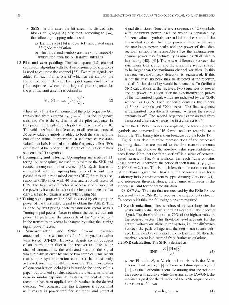
signal distortions. Nonetheless, a sequence of 20 symbolswith maximum power, each of which is separated by50 zero-valued symbols, are added to the start of thetransmitted signal. The large power difference betweenthe maximum power peaks and the power of the “datasection” symbols is reasonable since the instantaneouschannel power may fluctuate by as much as 20 dB due tofast fading [40], [41]. The power difference between thesynchronization section and the remaining sections is setto be larger than the maximum channel variation. In thismanner, successful peak detection is guaranteed. If thisis not the case, no peak may be detected at the receiver,and all further decoding would be erroneous. To facilitateSNR calculations at the receiver, two sequences of powerand no power are added after the synchronization pulsesof the transmitted signal, which are indicated by the “SNRsection” in Fig. 5. Each sequence contains five blocksof 50000 symbols and 50000 zeros. The first sequenceis transmitted from the first antenna, whereas the secondantenna is off. The second sequence is transmitted fromthe second antenna, whereas the first antenna is off.
After the DSP-Tx process is completed, the transmit vectorsymbols are converted to I16 format and are recorded to abinary file. This binary file is then broadcast by the PXIe-Tx.
Fig. 5 is an absolute value representation of the processedincoming data that are passed to the first transmit antenna(Tx1), and Fig. 6 shows the absolute value representation ofeach frame. Note that the “data section” is a series of concate-nated frames. In Fig. 6, it is shown that each frame contains26100 samples. Therefore, the period of each frame is TFrame =26100/fs = 2.6 ms. This is much less than the coherence timeof the channel given that, typically, the coherence time for astationary indoor environment is approximately 7 ms (see [41],and references therein). Hence, the channel estimation at thereceiver is valid for the frame duration.
2) DSP-Rx: The data that are received by the PXIe-Rx areprocessed by the DSP-Rx to recover the original data stream.To accomplish this, the following steps are required.
2.1 Synchronization: This is achieved by searching for thepeaks with a value above a certain threshold in the receivedsignal. The threshold is set as 70% of the highest value inthe received vector. This threshold level accounts for thenatural voltage variations in the system, i.e., the differencebetween the peak voltage and the root-mean-square volt-age. If the number of peaks found is less than 20, then thereceived vector is discarded from further calculations.
2.2 SNR calculation: The SNR is defined as
SNR =E[‖Hx‖2F
]σ2n
(3)
where H is the Nr ×Nt channel matrix, x is the Nt ×1 transmitted vector, E[·] is the expectation operator, and‖ · ‖F is the Forbenius norm. Assuming that the noise atthe receiver is additive white Gaussian noise (AWGN), thereceived signal for the duration of the SNR sequence canbe written as follows:
y = hntst + n (4)
SERAFIMOVSKI et al.: PRACTICAL IMPLEMENTATION OF SPATIAL MODULATION 4515
Fig. 5. Absolute value representation of the transmission vector being sentto Tx1. The synchronization, SNR estimation, and data sections are shown. Thevalue of the peak must be equal to 215 since the 16bit-Digitizer operates usingan I16 format before tuning the signal power of the data. The highest valuein the SNR section is the same as the highest value in the information datasection, which in this example, is a value of 2896. The peak value is 215. Thereis approximately a 21.1 dB difference between the peak power in the synchro-nization section and the peak power in the SNR estimation and data sections.This is apparent when looking at the two data points shown in the figure.
Fig. 6. Absolute value representation of a single frame from the vectorbeing transmitted by Tx1 in the I16 data format, which is a signed 15-bitrepresentation of an integer number.
where y is the Nr×1 received vector, hntis the nt column
of the channel matrix H, n is the Nr×1 AWGN vector withσ2n variance and μn mean, and st is the transmitted symbol
from the nt antenna. As mentioned in Section II-B1, onlya single transmit antenna is active when broadcasting theSNR sequence, and st is either equal to the maximum valuein the “data section” xmax or zero, as shown in Fig. 5.Hence, the received signal in (4) can be rewritten as
y =
{hnt
xmax + n, st = xmax
n, st = 0.(5)
Proceeding from (5)
E[‖Hx‖2F
]=E
[‖y − n‖2F
](6)
σ2n =E
[‖n‖2F
]− E [‖n‖]2 (7)
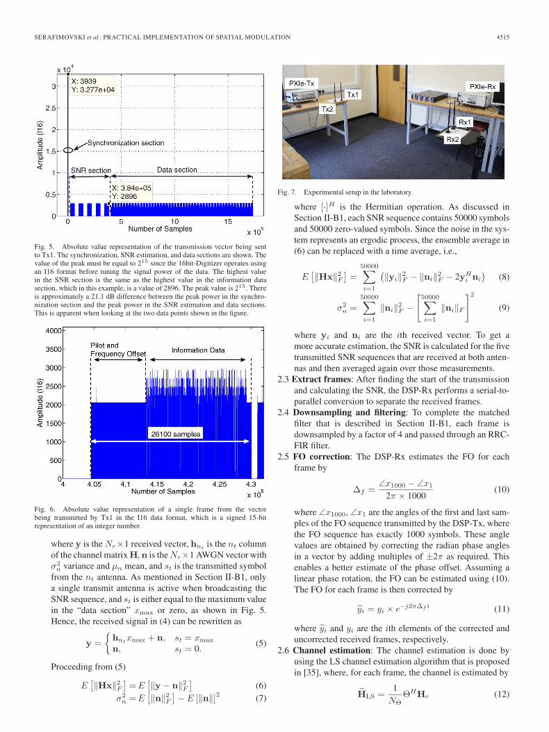
Fig. 7. Experimental setup in the laboratory.
where [·]H is the Hermitian operation. As discussed inSection II-B1, each SNR sequence contains 50000 symbolsand 50000 zero-valued symbols. Since the noise in the sys-tem represents an ergodic process, the ensemble average in(6) can be replaced with a time average, i.e.,
E[‖Hx‖2F
]=
50000∑i=1
(‖yi‖2F − ‖ni‖2F − 2yH
i ni
)(8)
σ2n =
50000∑i=1
‖ni‖2F −[50000∑i=1
‖ni‖F
]2
(9)
where yi and ni are the ith received vector. To get amore accurate estimation, the SNR is calculated for the fivetransmitted SNR sequences that are received at both anten-nas and then averaged again over those measurements.
2.3 Extract frames: After finding the start of the transmissionand calculating the SNR, the DSP-Rx performs a serial-to-parallel conversion to separate the received frames.
2.4 Downsampling and filtering: To complete the matchedfilter that is described in Section II-B1, each frame isdownsampled by a factor of 4 and passed through an RRC-FIR filter.
2.5 FO correction: The DSP-Rx estimates the FO for eachframe by
Δf =∠x1000 − ∠x1
2π × 1000(10)
where ∠x1000, ∠x1 are the angles of the first and last sam-ples of the FO sequence transmitted by the DSP-Tx, wherethe FO sequence has exactly 1000 symbols. These anglevalues are obtained by correcting the radian phase anglesin a vector by adding multiples of ±2π as required. Thisenables a better estimate of the phase offset. Assuming alinear phase rotation, the FO can be estimated using (10).The FO for each frame is then corrected by
yi = yi × e−j2πΔf i (11)
where yi and yi are the ith elements of the corrected anduncorrected received frames, respectively.
2.6 Channel estimation: The channel estimation is done byusing the LS channel estimation algorithm that is proposedin [35], where, for each frame, the channel is estimated by
HLS =1NΘ
ΘHHr (12)
4516 IEEE TRANSACTIONS ON VEHICULAR TECHNOLOGY, VOL. 62, NO. 9, NOVEMBER 2013
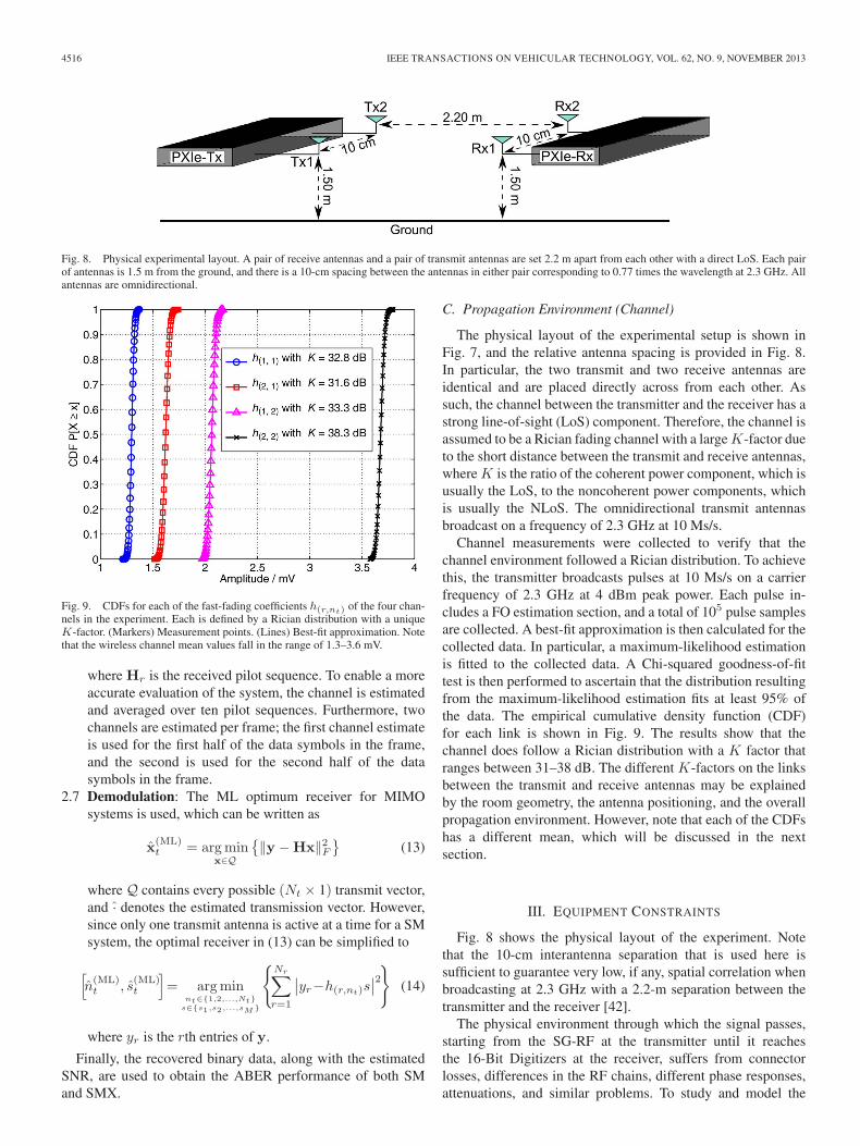
Fig. 8. Physical experimental layout. A pair of receive antennas and a pair of transmit antennas are set 2.2 m apart from each other with a direct LoS. Each pairof antennas is 1.5 m from the ground, and there is a 10-cm spacing between the antennas in either pair corresponding to 0.77 times the wavelength at 2.3 GHz. Allantennas are omnidirectional.
Fig. 9. CDFs for each of the fast-fading coefficients h(r,nt) of the four chan-nels in the experiment. Each is defined by a Rician distribution with a uniqueK-factor. (Markers) Measurement points. (Lines) Best-fit approximation. Notethat the wireless channel mean values fall in the range of 1.3–3.6 mV.
where Hr is the received pilot sequence. To enable a moreaccurate evaluation of the system, the channel is estimatedand averaged over ten pilot sequences. Furthermore, twochannels are estimated per frame; the first channel estimateis used for the first half of the data symbols in the frame,and the second is used for the second half of the datasymbols in the frame.
2.7 Demodulation: The ML optimum receiver for MIMOsystems is used, which can be written as
x(ML)t = argmin
x∈Q
{‖y −Hx‖2F
}(13)
where Q contains every possible (Nt × 1) transmit vector,and · denotes the estimated transmission vector. However,since only one transmit antenna is active at a time for a SMsystem, the optimal receiver in (13) can be simplified to
[n(ML)t , s
(ML)t
]= argmin
nt∈{1,2,...,Nt}s∈{s1,s2,...,sM}
{Nr∑r=1
∣∣yr−h(r,nt)s∣∣2} (14)
where yr is the rth entries of y.
Finally, the recovered binary data, along with the estimatedSNR, are used to obtain the ABER performance of both SMand SMX.
C. Propagation Environment (Channel)
The physical layout of the experimental setup is shown inFig. 7, and the relative antenna spacing is provided in Fig. 8.In particular, the two transmit and two receive antennas areidentical and are placed directly across from each other. Assuch, the channel between the transmitter and the receiver has astrong line-of-sight (LoS) component. Therefore, the channel isassumed to be a Rician fading channel with a large K-factor dueto the short distance between the transmit and receive antennas,where K is the ratio of the coherent power component, which isusually the LoS, to the noncoherent power components, whichis usually the NLoS. The omnidirectional transmit antennasbroadcast on a frequency of 2.3 GHz at 10 Ms/s.
Channel measurements were collected to verify that thechannel environment followed a Rician distribution. To achievethis, the transmitter broadcasts pulses at 10 Ms/s on a carrierfrequency of 2.3 GHz at 4 dBm peak power. Each pulse in-cludes a FO estimation section, and a total of 105 pulse samplesare collected. A best-fit approximation is then calculated for thecollected data. In particular, a maximum-likelihood estimationis fitted to the collected data. A Chi-squared goodness-of-fittest is then performed to ascertain that the distribution resultingfrom the maximum-likelihood estimation fits at least 95% ofthe data. The empirical cumulative density function (CDF)for each link is shown in Fig. 9. The results show that thechannel does follow a Rician distribution with a K factor thatranges between 31–38 dB. The different K-factors on the linksbetween the transmit and receive antennas may be explainedby the room geometry, the antenna positioning, and the overallpropagation environment. However, note that each of the CDFshas a different mean, which will be discussed in the nextsection.
III. EQUIPMENT CONSTRAINTS
Fig. 8 shows the physical layout of the experiment. Notethat the 10-cm interantenna separation that is used here issufficient to guarantee very low, if any, spatial correlation whenbroadcasting at 2.3 GHz with a 2.2-m separation between thetransmitter and the receiver [42].
The physical environment through which the signal passes,starting from the SG-RF at the transmitter until it reachesthe 16-Bit Digitizers at the receiver, suffers from connectorlosses, differences in the RF chains, different phase responses,attenuations, and similar problems. To study and model the
SERAFIMOVSKI et al.: PRACTICAL IMPLEMENTATION OF SPATIAL MODULATION 4517
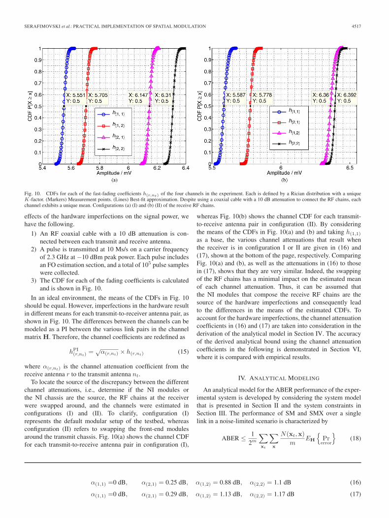
Fig. 10. CDFs for each of the fast-fading coefficients h(r,nt) of the four channels in the experiment. Each is defined by a Rician distribution with a uniqueK-factor. (Markers) Measurement points. (Lines) Best-fit approximation. Despite using a coaxial cable with a 10 dB attenuation to connect the RF chains, eachchannel exhibits a unique mean. Configurations (a) (I) and (b) (II) of the receive RF chains.
effects of the hardware imperfections on the signal power, wehave the following.
1) An RF coaxial cable with a 10 dB attenuation is con-nected between each transmit and receive antenna.
2) A pulse is transmitted at 10 Ms/s on a carrier frequencyof 2.3 GHz at −10 dBm peak power. Each pulse includesan FO estimation section, and a total of 105 pulse sampleswere collected.
3) The CDF for each of the fading coefficients is calculatedand is shown in Fig. 10.
In an ideal environment, the means of the CDFs in Fig. 10should be equal. However, imperfections in the hardware resultin different means for each transmit-to-receiver antenna pair, asshown in Fig. 10. The differences between the channels can bemodeled as a PI between the various link pairs in the channelmatrix H. Therefore, the channel coefficients are redefined as
hPI(r,nt)
=√α(r,nt) × h(r,nt) (15)
where α(r,nt) is the channel attenuation coefficient from thereceive antenna r to the transmit antenna nt.
To locate the source of the discrepancy between the differentchannel attenuations, i.e., determine if the NI modules orthe NI chassis are the source, the RF chains at the receiverwere swapped around, and the channels were estimated inconfigurations (I) and (II). To clarify, configuration (I)represents the default modular setup of the testbed, whereasconfiguration (II) refers to swapping the front-end modulesaround the transmit chassis. Fig. 10(a) shows the channel CDFfor each transmit-to-receive antenna pair in configuration (I),
whereas Fig. 10(b) shows the channel CDF for each transmit-to-receive antenna pair in configuration (II). By consideringthe means of the CDFs in Fig. 10(a) and (b) and taking h(1,1)
as a base, the various channel attenuations that result whenthe receiver is in configuration I or II are given in (16) and(17), shown at the bottom of the page, respectively. ComparingFig. 10(a) and (b), as well as the attenuations in (16) to thosein (17), shows that they are very similar. Indeed, the swappingof the RF chains has a minimal impact on the estimated meanof each channel attenuation. Thus, it can be assumed thatthe NI modules that compose the receive RF chains are thesource of the hardware imperfections and consequently leadto the differences in the means of the estimated CDFs. Toaccount for the hardware imperfections, the channel attenuationcoefficients in (16) and (17) are taken into consideration in thederivation of the analytical model in Section IV. The accuracyof the derived analytical bound using the channel attenuationcoefficients in the following is demonstrated in Section VI,where it is compared with empirical results.
IV. ANALYTICAL MODELING
An analytical model for the ABER performance of the exper-imental system is developed by considering the system modelthat is presented in Section II and the system constraints inSection III. The performance of SM and SMX over a singlelink in a noise-limited scenario is characterized by
ABER ≤ 12m
∑xt
∑x
N(xt,x)
mEH
{Prerror
}(18)
α(1,1) =0 dB, α(2,1) = 0.25 dB, α(1,2) = 0.88 dB, α(2,2) = 1.1 dB (16)
α(1,1) =0 dB, α(2,1) = 0.29 dB, α(1,2) = 1.13 dB, α(2,2) = 1.17 dB (17)
4518 IEEE TRANSACTIONS ON VEHICULAR TECHNOLOGY, VOL. 62, NO. 9, NOVEMBER 2013
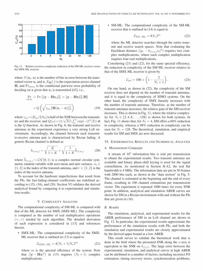
Fig. 11. Relative receiver complexity reduction of the SM-ML receiver versusthe SMX-ML receiver.
where N(xt,x) is the number of bits in error between the trans-mitted vector xt and x, EH{·} is the expectation across channelH, and Prerror is the conditional pairwise error probability ofdeciding on x given that xt is transmitted [43], i.e.,
Prerror
= Pr(‖y −Hxt‖2F > ‖y −Hx‖2F |H
)=Q
(√γex ‖H(xt − x)‖2F
)(19)
where γex=(Em/2N0) is half of the SNR between the transmit-ter and the receiver, and Q(ω)=(1/
√2π)
∫∞ω exp(−(t2/2)) dt
is the Q-function. As shown in Fig. 8, the transmit and receiveantennas in the experiment experience a very strong LoS en-vironment. Accordingly, the channel between each transmit-to-receive antenna pair is characterized by Rician fading. Ageneric Rician channel is defined as
h(r,nt) =
√K
1 +K+
√1
1 +Kh(r,nt) (20)
where h(r,nt) ∼ CN (0, 1) is a complex normal circular sym-metric random variable with zero mean and unit variance. nt ∈{1, 2} is the index of the transmit antenna, and r ∈ {1, 2} is theindex of the receive antenna.
To account for the hardware imperfections that result fromthe PIs, the fast-fading-channel coefficients are redefined ac-cording to (15), (16), and (20). Section VI validates the derivedanalytical bound by comparing it to experimental and simula-tion results.
V. COMPLEXITY ANALYSIS
The computational complexity of SM-ML is compared withthat of the ML detector for SMX (SMX-ML). The complexityis computed as the number of real multiplicative operations(×,÷) needed by each algorithm. The detailed derivationof each expression is considered in [13] and referencestherein.
• SMX-ML: The computational complexity of the SMX-ML receiver that is outlined in (13) is equal to
CSMX−ML = 4(Nt + 1)Nr2m (21)
where m is the spectral efficiency of the system. Notethat (|y −Hx|2) in (13) requires (Nt + 1) complexmultiplications.
• SM-ML: The computational complexity of the SM-MLreceiver that is outlined in (14) is equal to
CSM−ML = 8Nr2m (22)
where the ML detector searches through the entire trans-mit and receive search spaces. Note that evaluating theEuclidean distance (|yr − h(r,nt)st|2) requires two com-plex multiplications, where each complex multiplicationrequires four real multiplications.
Considering (21) and (22), for the same spectral efficiency,the reduction in complexity of the SM-ML receiver relative tothat of the SMX-ML receiver is given by
Crel = 100 ×(
1 − 2Nt + 1
). (23)
On one hand, as shown in (22), the complexity of the SMreceiver does not depend on the number of transmit antennas,and it is equal to the complexity of SIMO systems. On theother hand, the complexity of SMX linearly increases withthe number of transmit antennas. Therefore, as the number oftransmit antennas increases, the relative gain of the SM receiverincreases. This is shown in Fig. 11, where the relative complex-ity for Nt ∈ {2, 4, 8, . . . , 128} is shown for both systems. Infact, Fig. 11 shows that, for Nt = 4, SM offers a 60% reductionin complexity, whereas a 98% reduction in complexity can beseen for Nt = 128. The theoretical, simulation, and empiricalresults for SM and SMX are now discussed.
VI. EXPERIMENTAL RESULTS AND NUMERICAL ANALYSIS
A. Measurement Campaign
A stream of 105 information bits is sent per transmissionto obtain the experimental results. Two transmit antennas areavailable and binary phase-shift keying is used for the signalconstellation. As mentioned in Section II-A2, the real flatbandwidth is 4 MHz. The information data are put in 50 frameswith 2000 bits each, as shown in the “data section” in Fig. 5.The channel is estimated at the beginning and the end of everyframe, resulting in 100 channel estimations per transmissionvector. The experiment is repeated 1000 times for every SNRpoint. In addition, analytical and simulation ABER curves areshown for SM in a Rician environment with and without the PIsthat are given in (16).
B. Results
The simulation, analytical, and experimental results for theABER performance of SM in an LoS channel are shown inFig. 12. In particular, the experimental results approximate theperformance of the simulation results with PIs, and both thesimulation and experimental results are closely approximatedby the derived upper bound at a low ABER.
This result serves to validate the theoretical work that isdone in the field where the presented SNR along the x-axis isequivalent to the SNR on h(1,1). The large error between theexperimental, simulation, and analytical curves at high ABERcan be attributed to a number of factors, including incorrect FOestimation, timing recovery errors, synchronization problems,

SERAFIMOVSKI et al.: PRACTICAL IMPLEMENTATION OF SPATIAL MODULATION 4519
and poor channel estimation and decoding. Notably, incorrectFO estimation can result in a systematic error that is signifi-cantly contributing to the 30% error that are shown at low SNRsin the figure. As the SNR increases, however, FO estimation,timing recovery, and channel estimation improve, leading toa lower ABER, as shown in Fig. 12. Differences betweenthe measured and simulated ABER curves can be attributedto channel imperfections such as channel correlations, mutualcoupling, and interference signals from the surrounding envi-ronment. Quantifying these imperfections is deemed importantand requires channel modeling and interference measurement.However, addressing these effects is beyond the scope of thispaper and will be the subject of future works.
SM performs best in a rich scattering environment where thechannel between each transmit and receive antenna is unique.In particular, the larger the Euclidean distance between tworeceived vectors is, the better the ABER performance of SMbecomes. Conversely, the more similar the channels are, theworse the ABER of SM is. However, the channel uniquenesscan be the result of the scattering environment or PIs that arecaused by hardware tolerances. The analytical and simulationresults in Fig. 12 show the poor performance of SM in a Ricianenvironment with no PI between the various transmitter-to-receiver links. Fig. 12 also shows the analytical and simulationABERs for SM when PI are introduced. Indeed, the ABERof SM significantly improves when these PIs are introduced,as each channel becomes more separable. This increases theEuclidean distance and improves performance.
If the channels between each transmit antenna to each receiveantenna are similar, then the ABER performance of SM de-grades. This is seen when looking at the SM system without PIs,which is shown by the dashed green line with triangular markersin Fig. 12. In fact, the ABER of SM can be approximatedby separating the error that originates from the estimation ofthe spatial-constellation symbol and the error that originatesfrom the estimation of the signal-constellation symbol [44].Therefore, depending on the environment, the main contributorto the overall ABER of a SM system will be the erroneousdetection of the spatial or signal constellation.
When PIs are introduced, the Euclidean distance between thechannel signatures increases. This decreases the error contribu-tion of the spatial component of SM. Hence, when the SNR issufficiently high to have near-perfect channel estimation, theerror of the system is bounded by the error from the signalcomponent of SM. This separation can be only shown wheniterative detection is used, which is proven to be suboptimal[12]. In addition, in [45], it is shown that the error, when onlythe spatial constellation of SM is used for data transmission,gets worse for an increasing K factor in a Rician environment.This is the opposite of conventional modulation techniquessince a larger K factor for SM means a smaller Euclideandistance between the spatial-constellation points, which resultsin an increased ABER performance. Indeed, it is the Euclideandistance between the different channels that determines theerror in the spatial-constellation detection. However, since ML-optimal detection is used at the receiver, separating the errorfrom the spatial and signal symbols is strictly not permitted.Please note that the PIs between the links are always obtained
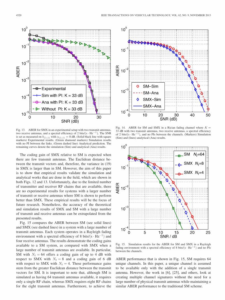
Fig. 12. ABER for SM in an experimental setup with two transmit antennas,two receive antennas, and a spectral efficiency of 2 bits/(s · Hz−1). The SNRis set as measured on h(1,1) with α(1,1) = 0 dB. (Solid black line with squaremarkers) Experimental results. (Green diamond markers) Simulation resultswith no PI between the links. (Green dashed line) Analytical prediction. Theremaining curves denote the simulation (Sim) and analytical (Ana) results.
relative to the channel with the greatest attenuation, i.e., thevalues of the PI factors in (16) and (17) are always positive.
Furthermore, PIs between the transmitting antennas areshown to offer improved performance in terms of the ABERwhen only the spatial constellation of SM is used, i.e., whenspace shift keying (SSK) is the underlying modulation tech-nique. In particular, an optimized power allocation for a variousnumber of transmit antennas is addressed in [23], where theauthors show that there is optimal power allocation betweenthe transmitting antennas, which can serve to increases theEuclidean distance between the channel signatures and im-prove the ABER performance of SM. Indeed, SM has beenalso successfully applied to an AWGN optical wireless chan-nel, where it is shown that PIs greatly improve the ABERperformance [46].
The simulation, analytical, and experimental results for theABER performance of SMX in a LoS channel are shown inFig. 13. In particular, the experimental results closely followthe performance of the simulation results with PIs, and both thesimulation and experimental results are closely approximatedby the derived upper bound at low ABER when the hardwareimperfections are taken into account. This result serves tovalidate the theoretical work that is done in the field. The resultsin Fig. 13 show that the SMX system, like the SM system,also benefits from the PIs in the hardware. The SMX systemapproximately exhibits a 3 dB coding gain when compared withSM at an ABER of 10−4. This coding gain is also shown at anABER of 10−3 in Fig. 14, where the simulation and analyticalresults for the ABER performance of SM and SMX are shownwhen there are no PIs between the links.
4520 IEEE TRANSACTIONS ON VEHICULAR TECHNOLOGY, VOL. 62, NO. 9, NOVEMBER 2013
Fig. 13. ABER for SMX in an experimental setup with two transmit antennas,two receive antennas, and a spectral efficiency of 2 bits/(s · Hz−1). The SNRis set as measured on h(1,1) with α(1,1) = 0 dB. (Solid black line with squaremarkers) Experimental results. (Green diamond markers) Simulation resultswith no PI between the links. (Green dashed line) Analytical prediction. Theremaining curves denote the simulation (Sim) and analytical (Ana) results.
The coding gain of SMX relative to SM is expected whenthere are few transmit antennas. The Euclidean distance be-tween the transmit vectors and, therefore, the variance in (19)in SMX is larger than in SM. However, the aim of this paperis to show that empirical results validate the simulation andanalytical works that are done in the field, which are shown inboth Figs. 12 and 13. Unfortunately, due to the limited numberof transmitter and receiver RF chains that are available, thereare no experimental results for systems with a larger numberof transmit or receive antennas where SM is shown to performbetter than SMX. These empirical results will be the focus offuture research. Nonetheless, the accuracy of the theoreticaland simulation results of SMX and SM with a large numberof transmit and receive antennas can be extrapolated from thepresented results.
Fig. 15 compares the ABER between SM (see solid lines)and SMX (see dashed lines) in a system with a large number oftransmit antennas. Each system operates in a Rayleigh fadingenvironment with a spectral efficiency of 8 bits/(s · Hz−1) andfour receive antennas. The results demonstrate the coding gainsavailable to a SM system, as compared with SMX when alarge number of transmit antennas are available. In particular,SM with Nt = 64 offers a coding gain of up to 4 dB withrespect to SMX with Nt = 8 and a coding gain of 6 dBwith respect to SMX with Nt = 4. These performance gainsstem from the greater Euclidean distance between the transmitvectors for SM. It is important to note that, although SM issimulated as having 64 transmit antennas available, it requiresonly a single RF chain, whereas SMX requires eight RF chainsfor the eight transmit antennas. Furthermore, to achieve the
Fig. 14. ABER for SM and SMX in a Rician fading channel where K =33 dB with two transmit antennas, two receive antennas, a spectral efficiencyof 2 bits/(s · Hz−1), and no PIs between the channels. (Markers) Simulation(Sim) and (lines) analytical (Ana) results.
Fig. 15. Simulation results for the ABER for SM and SMX in a Rayleighfading environment with a spectral efficiency of 8 bits/(s · Hz−1) and no PIsbetween the channels.
ABER performance that is shown in Fig. 15, SM requires 64unique channels. In this paper, a unique channel is assumedto be available only with the addition of a single transmitantenna. However, the work in [6], [25], and others, look atcreating multiple channel signatures without the need for alarge number of physical transmit antennas while maintaining asimilar ABER performance to the traditional SM scheme.
SERAFIMOVSKI et al.: PRACTICAL IMPLEMENTATION OF SPATIAL MODULATION 4521
This paper demonstrates that the hardware tolerances ofpractical communication systems are beneficial for the ABERperformance of both SM and SMX. This behavior, along withthe requirement for a single RF chain, makes SM a viablecandidate for future wireless networks.
VII. SUMMARY AND CONCLUSION
In this paper, the ABER performance of SM and SMX hasbeen experimentally validated for the first time. In particular,the encoding and decoding processes have been presented. Theexperimental testbed, equipment, and channel conditions havebeen described in detail, and the ABERs of SM and SMXhave been obtained in a practical testbed environment. In ad-dition, the experimental results have been compared with bothsimulation and analytical approaches. As a result, it has beenshown that a Rician channel with different channel attenuationsclosely describe the behavior of SM and SMX in the physicalenvironment. Furthermore, it has been demonstrated that thedifferent channel attenuations resulted from various hardwareimperfections at the transmitter and receiver RF chains. In fact,the induced PIs resulted in significant coding gains for thepractical systems that are relative to the theoretical predictionswithout such PIs. To this extent, SM and SMX performed asexpected, relative to the theoretical work when the PIs havebeen introduced in the analytical model. This result validatedthe SM principle. The performance gains exhibited by SM inthe practical implementation make SM a viable candidate forfuture wireless networks and, particularly, for systems with alarge number of transmit antennas available.
It is worth noting that this paper may be extended in anumber of different ways that would broaden its applicability.Empirical results that demonstrate the performance of SMand SMX with a large number of transmit and receive an-tennas remain to be obtained. In light of the aforementionedresults, the ABER performance of SM and SMX is expected tofollow the theoretical models, but these results are essentialto validate the ABER performance for both SM and SMXsystems. In addition, channel imperfections such as channelcorrelations and mutual antenna coupling, along with the im-pact of interfering signals from neighboring transmitters on thesame frequency, should be analyzed. Furthermore, obtainingempirical results for the capacity and the energy efficiencyof SM are of great interest for future research, particularlysince SM is projected to have large energy efficiency gainswhen compared with other traditional MIMO schemes sinceit requires only a single RF chain. As a consequence, thequiescent power and circuit power can be kept at low levels.Acquiring the hardware, which would enable the accuratemeasurement of these aspects, is key. Finally, the implemen-tation of the SM detection algorithm on a DSP or a field-programmable gate array (FPGA) brings with it a numberof optimization challenges such as the use of multithread-ing, pipelining, fixed-point computations, and others. Thedeployment of SM on an FPGA or a DSP has yet to bedemonstrated.
It has been shown that SM is a simple low-cost MIMOtechnique, which has now demonstrated excellent performance
in an LoS wireless channel. Therefore, this paper has shownthat SM is a promising practical approach to obtaining theenhanced performance of SMX without introducing high pro-cessor complexity and high power consumption that wouldoccur when using other SMX approaches. The aim now is toinvestigate the performance of SM in a range of experimentalchannel conditions and further study its potential.
REFERENCES
[1] E. Telatar, “Capacity of multi-antenna Gaussian channels,” Eur. Trans.Telecommun., vol. 10, no. 6, pp. 585–595, Nov./Dec. 1999.
[2] J. Mietzner, R. Schober, L. Lampe, W. H. Gerstacker, and P. A. Höeher,“Multiple-antenna techniques for wireless communications—A compre-hensive literature survey,” IEEE Commun. Surveys Tuts., vol. 11, no. 2,pp. 87–105, Second Quart., 2009.
[3] R. Mesleh, H. Haas, Y. Lee, and S. Yun, “Interchannel interference avoid-ance in MIMO transmission by exploiting spatial information,” in Proc.16th IEEE Int. Symp. PIMRC, Berlin, Germany, 2005, vol. 1, pp. 141–145.
[4] R. Mesleh, H. Haas, S. Sinanovi, C. W. Ahn, and S. Yun, “Spatialmodulation,” IEEE Trans. Veh. Technol., vol. 57, no. 4, pp. 2228–2241,Jul. 2008.
[5] N. Serafimovski, M. Di Renzo, S. Sinanovi, R. Y. Mesleh, and H. Haas,“Fractional bit encoded spatial modulation (FBE-SM),” IEEE Commun.Lett., vol. 14, no. 5, pp. 429–431, May 2010.
[6] A. Younis, N. Serafimovski, R. Mesleh, and H. Haas, “Generalised spa-tial modulation,” in Proc. Asilomar Conf. Signals, Syst. Comput., PacificGrove, CA, USA, Nov. 2010, pp. 1498–1502.
[7] J. Jeganathan, A. Ghrayeb, L. Szczecinski, and A. Ceron, “Space shiftkeying modulation for MIMO channels,” IEEE Trans. Wireless Commun.,vol. 8, no. 7, pp. 3692–3703, Jul. 2009.
[8] G. Auer, V. Giannini, C. Desset, I. Godor, P. Skillermark, M. Olsson,M. Imran, D. Sabella, M. Gonzalez, O. Blume, and A. Fehske, “Howmuch energy is needed to run a wireless network?” IEEE WirelessCommun., vol. 18, no. 5, pp. 40–49, Oct. 2011.
[9] C. Desset, B. Debaillie, V. Giannini, A. Fehske, G. Auer, H. Holtkamp,W. Wajda, D. Sabella, F. Richter, M. J. Gonzalez, H. Klessig, I. Godor,M. Olsson, M. A. Imran, A. Ambrosy, and O. Blume, “Flexible powermodeling of LTE base stations,” in Proc. IEEE WCNC, Shanghai, China,Apr. 1–4, 2012, pp. 2858–2862.
[10] A. Stavridis, S. Sinanovi, M. D. Renzo, H. Haas, and P. Grant, “Energysaving base station employing spatial modulation,” Proc. IEEE 17th Int.Workshop CAMAD, pp. 231–235, Sep. 17–19, 2012.
[11] A. Stavridis, S. Sinanovi, M. D. Renzo, and H. Haas, “A power savingdual-hop architecture based on hybrid spatial modulation,” in Conf. Rec.46th ASILOMAR, Nov. 4–7, 2012, pp. 1366–1370.
[12] J. Jeganathan, A. Ghrayeb, and L. Szczecinski, “Spatial modulation: Op-timal detection and performance analysis,” IEEE Commun. Lett., vol. 12,no. 8, pp. 545–547, Aug. 2008.
[13] A. Younis, S. Sinanovic, M. Di. Renzo, R. Mesleh, and H. Haas, “Gen-eralised sphere decoding for spatial modulation,” IEEE Trans. Commun.,vol. 61, no. 7, pp. 2805–2815, Jul. 2013.
[14] A. Younis, R. Mesleh, H. Haas, and P. M. Grant, “Reduced complexitysphere decoder for spatial modulation detection receivers,” in Proc. IEEEGLOBECOM, Miami, FL, USA, Dec. 2010, pp. 1–5.
[15] A. Younis, M. Di Renzo, R. Mesleh, and H. Haas, “Sphere decoding forspatial modulation,” in Proc. IEEE ICC, Kyoto, Japan, 2011, pp. 1–6.
[16] R. Mesleh, M. Di Renzo, H. Haas, and P. M. Grant, “Trellis coded spatialmodulation,” IEEE Trans. Wireless Commun., vol. 9, no. 7, pp. 2349–2361, Jul. 2010.
[17] M. Di Renzo and H. Haas, “A general framework for performance analysisof space shift keying (SSK) modulation for MISO correlated Nakagami-mfading channels,” IEEE Trans. Commun., vol. 58, no. 9, pp. 2590–2603,Sep. 2010.
[18] S. U. Hwang, S. Jeon, S. Lee, and J. Seo, “Soft-output ML detector forspatial modulation OFDM systems,” IEICE Electron. Exp., vol. 6, no. 19,pp. 1426–1431, Oct. 2009.
[19] M. Di Renzo and H. Haas, “Space shift keying (SSK) modulation withpartial channel state information: Optimal detector and performance anal-ysis over fading channels,” IEEE Trans. Commun., vol. 58, no. 11,pp. 3196–3210, Nov. 2010.
[20] S. S. Ikki and R. Mesleh, “A general framework for performance analysisof space shift keying (SSK) modulation in the presence of Gaussianimperfect estimations,” IEEE Commun. Lett., vol. 16, no. 2, pp. 228–230,Feb. 2012.
4522 IEEE TRANSACTIONS ON VEHICULAR TECHNOLOGY, VOL. 62, NO. 9, NOVEMBER 2013
[21] E. Basar, U. Aygolu, E. Panayirci, and H. V. Poor, “Performance of spatialmodulation in the presence of channel estimation errors,” IEEE Commun.Lett., vol. 16, no. 2, pp. 176–179, Feb. 2012.
[22] M. D. Renzo, D. D. Leonardis, F. Graziosi, and H. Haas, “Space shiftkeying (SSK) MIMO with practical channel estimates,” IEEE Trans.Commun., vol. 60, no. 4, pp. 998–1012, Apr. 2012.
[23] M. Di Renzo and H. Haas, “Improving the performance of space shiftkeying (SSK) modulation via opportunistic power allocation,” IEEE Com-mun. Lett., vol. 14, no. 6, pp. 500–502, Jun. 2010.
[24] T. Handte, A. Muller, and J. Speidel, “BER analysis and optimization ofgeneralized spatial modulation in correlated fading channels,” in Proc.IEEE VTC Fall, Anchorage, AK, USA, Sep. 20–23, 2009, pp. 1–5.
[25] E. Basar, U. Aygolu, E. Panayirci, and V. H. Poor, “Space-time blockcoded spatial modulation,” IEEE Trans. Commun., vol. 59, no. 3, pp. 823–832, Mar. 2011.
[26] M. Di Renzo and H. Haas, “On transmit-diversity for spatial modulationMIMO: Impact of spatial-constellation diagram and shaping filters at thetransmitter,” IEEE Trans. Veh. Technol., vol. 62, no. 6, pp. 2507–2531,Jul. 2013.
[27] N. Serafimovski, S. Sinanovic, M. Di Renzo, and H. Haas, “Dual-hopspatial modulation (Dh-SM),” in Proc. IEEE VTC Spring, Budapest,Hungary, May 15–18, 2011, pp. 1–5.
[28] A. Stavridis, S. Sinanovi, M. D. Renzo, and H. Haas, “Energy evaluationof spatial modulation at a multi-antenna base station,” in Proc. 78th IEEEVTC, Las Vegas, NV, USA, Sep. 2–5, 2013.
[29] M. Di Renzo and H. Haas, “Bit error probability of spatial modula-tion (SM) MIMO over generalized fading channels,” IEEE Trans. Veh.Technol., vol. 61, no. 3, pp. 1124–1144, Mar. 2012.
[30] A. Younis, W. Thompson, M. D. Renzo, C.-X. Wang, M. A. Beach,H. Haas, and P. M. Grant, “Performance of spatial modulation usingmeasured real-world channels,” in Proc. 78th IEEE VTC, Las Vegas, NV,USA, Sep. 2–5, 2013.
[31] M. Di Renzo, H. Haas, and P. M. Grant, “Spatial modulation for multiple-antenna wireless systems: A survey,” IEEE Commun. Mag, vol. 49, no. 12,pp. 182–191, Dec. 2011.
[32] “16-Bit IF Digitizer with Onboard Signal Processing,” NI PXIe-5622Specifications, National Instruments, 2011.
[33] P. Chambers, X. Hong, Z. Chen, C.-X. Wang, M. Beach, and H. Haas,“The UC4G wireless MIMO testbed,” in Proc. IEEE GLOBECOM,Anaheim, CA, USA, Dec. 3–7, 2012, pp. 4368–4373.
[34] G. J. Foschini, “Layered space–time architecture for wireless communi-cation in a fading environment when using multi-element antennas,” BellLabs Tech. J., vol. 1, no. 2, pp. 41–59, 1996.
[35] S. Tiiro, J. Ylioinas, M. Myllyla, and M. Juntti, “Implementation of theleast squares channel estimation algorithm for MIMO-OFDM systems,”in Proc. Int. ITG WSA, Berlin, Germany, 2009.
[36] L. Lo Presti and M. Mondin, “Design of optimal FIR raised-cosine filters,”Electron. Lett., vol. 25, no. 7, pp. 467–468, Mar. 1989.
[37] J. L. Massey, “Optimum frame synchronization,” IEEE Trans. Commun.,vol. 20, no. 2, pp. 115–119, Apr. 1972.
[38] H. Xuefei and C. Jie, “Implementation frame synchronization for MIMO-OFDM system with ZCZ-codes,” in Proc. IEEE Int. Symp. MAPE, 2005,vol. 1, pp. 241–244.
[39] J.-J. van de Beek, M. Sandell, M. Isaksson, and P. Ola Borjesson,“Low-complex frame synchronization in OFDM systems,” in Proc. IEEEInt. Conf. Universal Pers. Commun., Tokyo, Japan, Nov. 6–10, 1995,pp. 982–986.
[40] H. Hashemi, “The indoor radio propagation channel,” Proc. IEEE, vol. 81,no. 7, pp. 943–968, Jul. 1993.
[41] D. McNamara, M. Beach, and P. Fletcher, “Experimental investigation ofthe temporal variation of MIMO channels,” in Proc. IEEE 54th VTC Fall,Atlantic City, NJ, USA, 2001, vol. 2, pp. 1063–1067.
[42] F. Quitin, C. Oestges, F. Horlin, and P. D. Doncker, “MultipolarizedMIMO channel characteristics: analytical study and experimental re-sults,” IEEE Trans. Antennas Propag., vol. 57, no. 9, pp. 2739–2745,Sep. 2009.
[43] M. D. Renzo and H. Haas, “Performance analysis of spatial modulation,”in Proc. Int. ICST Conf. CHINACOM, Aug. 2010, pp. 1–7.
[44] M. Di Renzo and H. Haas, “Bit error probability of space modulation overNakagami-m fading: Asymptotic analysis,” IEEE Commun. Lett., vol. 15,no. 10, pp. 1026–1028, Oct. 2011.
[45] M. D. Renzo and H. Haas, “Space shift keying (SSK-) MIMO over corre-lated Rician fading channels: Performance analysis and a new method fortransmit-diversity,” IEEE Trans. Commun., vol. 59, no. 1, pp. 116–129,Jan. 2011.
[46] T. Fath, H. Haas, M. Di Renzo, and R. Mesleh, “Spatial modulationapplied to optical wireless communications in indoor LOS environments,”in Proc. IEEE GLOBECOM, Houston, TX, USA, 2011, pp. 1–5.
Nikola Serafimovski received the B.Sc. degree inelectrical engineering and computer science and theM.Sc. degree in communications, systems, and elec-tronics from Jacobs University, Bremen, Germany,in 2007 and 2009, respectively, and the Ph.D. degreefrom The University of Edinburgh, Edinburgh, U.K.,where the focus of his research was on multiple-inputmultiple-output systems and the practical implemen-tation of spatial modulation.
He is currently a Communication Systems Engi-neer with pureVLC Ltd, Edinburgh, U.K.
Abdelhamid Younis received the B.Sc. degree inelectrical and electronic engineering (with honors)in 2007 from the University of Benghazi, Benghazi,Libya, and the M.Sc. degree in signal processingand communication engineering (with distinction) in2009 from The University of Edinburgh, Edinburgh,U.K., where he is currently working toward the Ph.D.degree in communication engineering in the Instituteof Digital Communications.
His main research interests are in the area of wire-less communication and digital signal processing
with a particular focus on spatial modulation, multiple-input multiple-output(MIMO) wireless communications, reduced complexity MIMO design, andoptical wireless communications.
Mr. Younis received the Overseas Research Student Award in 2010 inrecognition of his work.
Raed Mesleh (S’00–M’08–SM’13) received thePh.D. degree in electrical engineering from JacobsUniversity, Bremen, Germany.
He had several years of postdoctoral wireless-communication and optical-wireless-communicationresearch experience in Germany. Since October 2010,he has been with the University of Tabuk, Tabuk,Saudi Arabia, where he is currently an AssistantProfessor and the Director of the research excel-lence unit. Since 2007, his publications have receivedmore than 800 citations. He has published more than
50 publications in top-tier journals and conferences. He is the holder of sevengranted patents. His main research interests are in spatial modulation, multiple-input multiple-output cooperative wireless communication techniques, andoptical wireless communication.
Dr. Mesleh serves on the Technical Program Committee for academic con-ferences and is a regular reviewer for most of the journals of the IEEE/OpticalSociety of America (OSA) Communication Society and the IEEE/OSA Pho-tonics Society.
P. Chambers received the B.Sc. degree in physicsand physics technology and the Ph.D. degree intransmission line and wireless communications fromthe Dublin Institute of Technology, Dublin, Ireland,in 2002 and 2008, respectively.
From to 2009 to 2010, he worked as a Post-doctoral Researcher with Université Catholique deLouvain, Louvain-la-Neuve, Belgium. Then, heworked as a Research Associate on the U.K.-ChinaScience Bridges: Research and Development on Be-yond Fourth-Generation Wireless Mobile Communi-
cations (UC4G) Project. From 2010 to 2013, he was with the Defence Scienceand Technology Laboratory, Heriot-Watt University, Edinburgh, U.K., workingon on the development of cognitive radio algorithms. He is currently a ResearchAssociate with the University of Surrey, Surrey, U.K., where he is working onfifth-generation communications standards as part of the Low-Electromagnetic-Field Exposure Network (LexNet) Project Team.
SERAFIMOVSKI et al.: PRACTICAL IMPLEMENTATION OF SPATIAL MODULATION 4523
Marco Di Renzo (S’05–AM’07–M’09) was born inL’Aquila, Italy, in 1978. He received the Laurea (cumlaude) and Ph.D. degrees in electrical and informa-tion engineering from the University of L’Aquila,Coppito, Italy, in 2003 and 2007, respectively.
From August 2002 to January 2008, he waswith the Center of Excellence for Research “De-sign Methodologies of Embedded Controllers, Wire-less Interconnect and Systems-on-chip (DEWS),”University of L’Aquila. From February 2008 toApril 2009, he was a Research Associate with the
Telecommunications Technological Center of Catalonia (CTTC), Barcelona,Spain. From May 2009 to December 2009, he was an Engineering and PhysicalSciences Research Council Research Fellow with the Institute for DigitalCommunications, The University of Edinburgh, Edinburgh, U.K. Since January2010, he has been a Tenured Researcher (“Chargé de Recherche Titulaire”) withthe French National Center for Scientific Research (CNRS), as well as a FacultyMember with the Laboratory of Signals and Systems, a joint research laboratoryof the CNRS, the École Supérieure d’ Électricité, and the University of Paris-Sud XI, Paris, France. His main research interests are in the area of wirelesscommunications theory. He is a Principal Investigator of three European-fundedresearch projects (Marie Curie ITN-GREENET, Marie Curie IAPP-WSN4QoL,and Marie Curie ITN-CROSSFIRE).
Dr. Di Renzo received the Special Mention for the Outstanding Five-Year(1997–2003) Academic Career, University of L’Aquila; the Thales Communi-cations fellowship for doctoral studies (2003–2006), University of L’Aquila;the Best Spinoff Company Award (2004), Abruzzo Region, Italy; the TorresQuevedo award for research on ultrawideband systems and cooperative local-ization for wireless networks (2008–2009), Ministry of Science and Innovation,Spain; the “Dérogation pour l’Encadrement de Thèse” (2010), University ofParis-Sud XI, France; the 2012 IEEE International Workshop on Computer-Aided Modeling Analysis and Design of Communication Links and NetworksBest Paper Award from the IEEE Communications Society; and the 2012Exemplary Reviewer Award from the IEEE WIRELESS COMMUNICATIONS
LETTERS of the IEEE Communications Society. He currently serves as anEditor of the IEEE COMMUNICATIONS LETTERS.
Cheng-Xiang Wang (S’01–M’05–SM’08) receivedthe B.Sc. and M.Eng. degrees in communicationand information systems from Shandong University,Jinan, China, in 1997 and 2000, respectively, andthe Ph.D. degree in wireless communications fromAalborg University, Aalborg, Denmark, in 2004.
Since 2005, he has been with Heriot-Watt Univer-sity, Edinburgh, U.K., where he was first a Lecturer,then a Reader in 2009, and has been a Professorsince 2011. He is also an Honorary Fellow with TheUniversity of Edinburgh, U.K., and a Chair/Guest
Professor with Shandong University, Huazhong University of Science andTechnology, Wuhan, China, and the Southeast University, Nanjing, China. Hewas a Research Fellow with the University of Agder, Grimstad, Norway, from2001 to 2005, a Visiting Researcher with Siemens AG-Mobile Phones, Munich,Germany, in 2004, and a Research Assistant with the Technical University ofHamburg-Harburg, Hamburg, Germany, from 2000 to 2001. He has publishedone book chapter and over 180 papers in refereed journals and conferenceproceedings. His current research interests include wireless channel modelingand simulation, green communications, cognitive radio networks, vehicularcommunication networks, large multiple-input multiple-output (MIMO), coop-erative MIMO, and Beyond Fourth-Generation wireless communications.
Prof. Wang served or is currently serving as an editor for eight internationaljournals, including the IEEE TRANSACTIONS ON VEHICULAR TECHNOLOGY
(2011 to present) and the IEEE TRANSACTIONS ON WIRELESS COMMU-NICATIONS (2007–2009). He was the Guest Editor for the IEEE JOURNAL
ON SELECTED AREAS IN COMMUNICATIONS, Special Issue on VehicularCommunications and Networks and Special Issue on Spectrum and EnergyEfficient Design of Wireless Communication Networks. He served or is servingas a Technical Program Committee (TPC) member, the TPC Chair, and theGeneral Chair for over 70 international conferences. He received the Best PaperAwards from the IEEE Global Communications Conference in 2010, the IEEEInternational Conference on Communication Technology in 2011, and The 12thInternational Conference on ITS Telecommunications (ITST 2012). He is aFellow of the Institution of Engineering and Technology, a Fellow of the HigherEducation Academy, and a member of the Engineering and Physical SciencesResearch Council Peer-Review College.
Peter M. Grant (M’77–SM’83–F’96) was born inSt. Andrews, U.K. He received the B.Sc. degree inelectronic engineering from the Heriot-Watt Univer-sity, Edinburgh, U.K., in 1966, the Ph.D. degreefrom The University of Edinburgh in 1975, and hon-orary D.Eng. degrees from the Heriot-Watt Univer-sity in 2006 and from Napier University, Edinburgh,in 2007.
He worked in radio communications with thePlessey Company. He was then appointed to a re-search fellowship with The University of Edinburgh,
where he was subsequently promoted to a Full Professor of electronic signalprocessing and a Departmental Chair. From 2002 to 2008, he served as the Headof the School of Engineering and Electronics, Edinburgh. During the academicyear 1977–1978, he was a Visiting Professor with the Ginzton Laboratory,Stanford University, Stanford, CA, USA, and from 1985 to 1986, he was aVisiting Staff Member with the Lincoln Laboratory, Massachusetts Institute ofTechnology, Lexington, MA, USA.
Prof. Grant received the 82nd Faraday Medal from the Institution of Elec-trical Engineers (IEE) for his work on code-division multiple-access receiverdesigns and adaptive filters in 2004, the Bulgin premium in 1974 and 1977and the Lord Mountbatten premium in 1982 from the then Institution ofElectronic and Radio Engineers, and both the IEE Marconi and LanghamThompson premia in 1994. From 1980 to 1996, he served as an HonoraryEditor of the IEE Proceedings entitled “Vision Image and Signal Processing.”He was a member in 1992 and 1996 and the Chair of the 2001 UniversitiesFunding Council research assessment panel for the U.K. Electrical EngineeringDepartments. He was the Technical Program Chairman for the InternationalConference on Acoustics, Speech, and Signal Processing in 1989, the Chairmanof the European Signal Processing Conference in 1994, and the Presidentof the European Association for Signal Processing (EURASIP) from 2000to 2002. In 1998, he was appointed by the IEEE Signal Processing Societyas a Distinguished Lecturer on digital signal processing for mobile commu-nications. He served as the Director of the Virtual Centre of Excellence InMobile and Personal Communications Limited from 2007 to 2009. In 2007,he was appointed to be the Eighth Regius Professor of Engineering with TheUniversity of Edinburgh. In 2009, he was made an Officer of the Order ofthe British Empire in the Queen’s birthday honors list. He holds fellowshipsof the Institution of Engineering and Technology, the Royal Academy ofEngineering, and the Royal Society of Edinburgh.
Mark A. Beach received the Ph.D. degree from theUniversity of Bristol, Bristol, U.K., in 1987.
He was a Research Assistant from September1987 to July 1989, a Lecturer from August 1989to July 1996, a Senior Lecturer from August 1996to July 1998, a Reader in communication systemsfrom August 1998 to July 2003, the Head of theDepartment of Electrical and Electronic Engineeringfrom August 2006 to July 2010, and has been aProfessor of radio systems engineering since August2003 with the University of Bristol.
Harald Haas (S’98–A’00–M’03) received thePh.D. degree from The University of Edinburgh,Edinburgh, U.K., in 2001.
He is the Chair of Mobile Communications withthe Institute for Digital Communications, The Uni-versity of Edinburgh, and he is currently the chieftechnical officer of a university spinout companypureVLC Ltd. He is the holder of 23 patents. Hehas published more than 60 journal papers, includinga Science article and more than 160 peer-reviewedconference papers. Nine of his papers are invited
papers. He has coauthored a book entitled Next Generation Mobile AccessTechnologies: Implementing TDD (Cambridge University Press). Since 2007,he has been a Regular High-Level Visiting Scientist supported by the Chinese111-program with Beijing University of Posts and Telecommunications,Beijing, China. He was an invited speaker at the Technology, Entertainment,Design Global Conference in 2011. His main research interests are in interfer-ence coordination in wireless networks, spatial modulation, and optical wirelesscommunication.
Prof. Haas received a prestigious Fellowship of the Engineering and PhysicalSciences Research Council, U.K. His work on optical wireless communicationwas listed among the “50 Best Inventions in 2011” in Time Magazine.