practical steps to a successful profibus project - xiu ji of the uk's picc
TRANSCRIPT

Practical Steps to a Successful PROFIBUS Project
Dr. Xiu Ji

Practical steps for a successful project, Xiu Ji. PROFIBUS Seminar at MTC, Coventry, 2013. Slide 2
Outline of this presentation
Basics of PROFIBUS Considerations at the design stage Installation - visual checks Summary – Steps to a successful PROFIBUS project
Practical steps for a successful project, Xiu Ji. PROFIBUS Seminar at MTC, Coventry, 2013. Slide 3
Introduction to PROFIBUS
Fieldbus is widely used in many automation systems.
PROFIBUS solutions for Factory Automation (FA) and Process Automation (PA)
Applications also involving drives, instruments, servos, robotics, functional safety, redundancy, and explosive environments etc.
Extensive diagnostic functions available to operators and maintenance engineers
Probably the single reason to use bus or networked devices and systems
Diagnostic tools available for engineering, commissioning, maintenance, and fault finding
Excellent support from PROFIBUS International, regional events and competence and training centres.

Practical steps for a successful project, Xiu Ji. PROFIBUS Seminar at MTC, Coventry, 2013. Slide 4
More Information
More adjustable settings and parameters (e.g. scaling, linearization and calibration). Diagnostic data to inform if measurement is valid.

Practical steps for a successful project, Xiu Ji. PROFIBUS Seminar at MTC, Coventry, 2013. Slide 5
Extensive Diagnostics
Controller
Engineering
Station
PA Software
SCADA/HMI
1
2
2
3
Analyser
Practical steps for a successful project, Xiu Ji. PROFIBUS Seminar at MTC, Coventry, 2013. Slide 6
The PROFIBUS Family
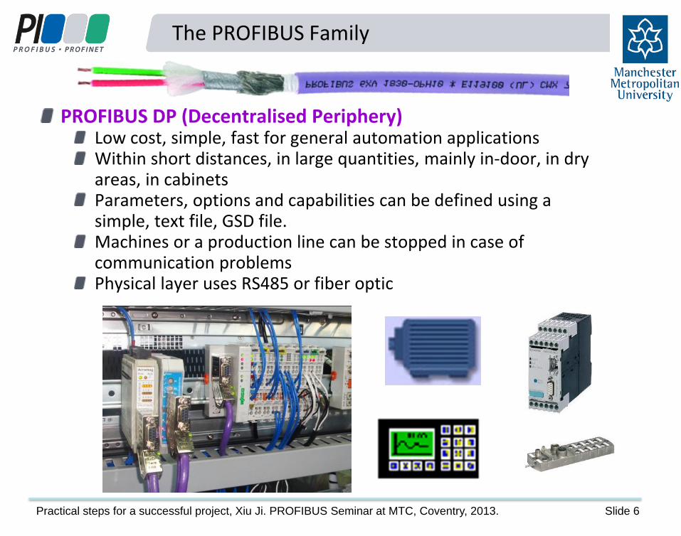
PROFIBUS DP (Decentralised Periphery) Low cost, simple, fast for general automation applications Within short distances, in large quantities, mainly in-door, in dry areas, in cabinets Parameters, options and capabilities can be defined using a simple, text file, GSD file. Machines or a production line can be stopped in case of communication problems Physical layer uses RS485 or fiber optic

Practical steps for a successful project, Xiu Ji. PROFIBUS Seminar at MTC, Coventry, 2013. Slide 7
The PROFIBUS Family
PROFIBUS PA (Process Automation) Developed specifically for the process industry to replace 4-20mA transmission Two-wire connection carrying both power and data Spread over long distances, in low quantities, mainly out-doors, in wet and exposed sites Parameters, options and capabilities are defined additional to a GSD file, also in EDD or FDT/DTM. Machines and processes cannot be stopped if there are only communication problems Large number of parameters, options and diagnostic events Cyclic and acyclic communications PA equipment is often used in explosive environments
Practical steps for a successful project, Xiu Ji. PROFIBUS Seminar at MTC, Coventry, 2013. Slide 8
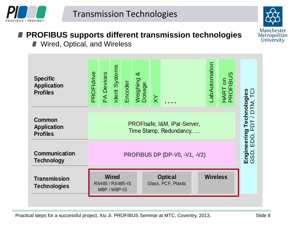
Transmission Technologies
Communication Technology
Transmission
Technologies
PROFIBUS DP (DP-V0, -V1, -V2)
Wired RS485 / RS485-IS
MBP / MBP-IS
En
gin
ee
rin
g T
ech
no
log
ies
GS
D,
ED
D,
FD
T /
DT
M,
TC
I
OpticalGlass, PCF, Plastic
Wireless
PR
OF
Idrive
PA
De
vic
es
En
co
de
r
Ide
nt
Syste
ms
Weig
hin
g &
D
osa
ge
HA
RT
on
PR
OF
IBU
S
Lab
Auto
matio
n
SpecificApplication Profiles
CommonApplication Profiles
XY
. . . .
PROFIsafe, I&M, iPar-Server, Time Stamp, Redundancy, …
PROFIBUS supports different transmission technologies Wired, Optical, and Wireless

Practical steps for a successful project, Xiu Ji. PROFIBUS Seminar at MTC, Coventry, 2013. Slide 9
Connection technologies
PROFIBUS DP uses 2-core shielded and twisted RS485 wiring. 9-pin sub-D or M12 connectors extensively used.
DP can also use plastic or glass fibre optic cabling.
ST/BFOC connectors widely used
PROFIBUS PA uses “Manchester Bus Powered” (MBP) cabling over 2 cores.
Glanded screw or M12 connection normally used
9

Practical steps for a successful project, Xiu Ji. PROFIBUS Seminar at MTC, Coventry, 2013. Slide 10
Fibre Optic
The implementation of a fibre optic cable network involves the use of electro optical converters (OBT and OLM):
for long distance, between buildings, and to solve grounding problem (grounds with un-even earth potential).
Fibre to Copper
OLM (Optical Link Module)
OBT (Optical Bus Terminal)
Practical steps for a successful project, Xiu Ji. PROFIBUS Seminar at MTC, Coventry, 2013. Slide 11
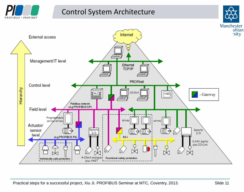
Control System Architecture
Practical steps for a successful project, Xiu Ji. PROFIBUS Seminar at MTC, Coventry, 2013. Slide 12
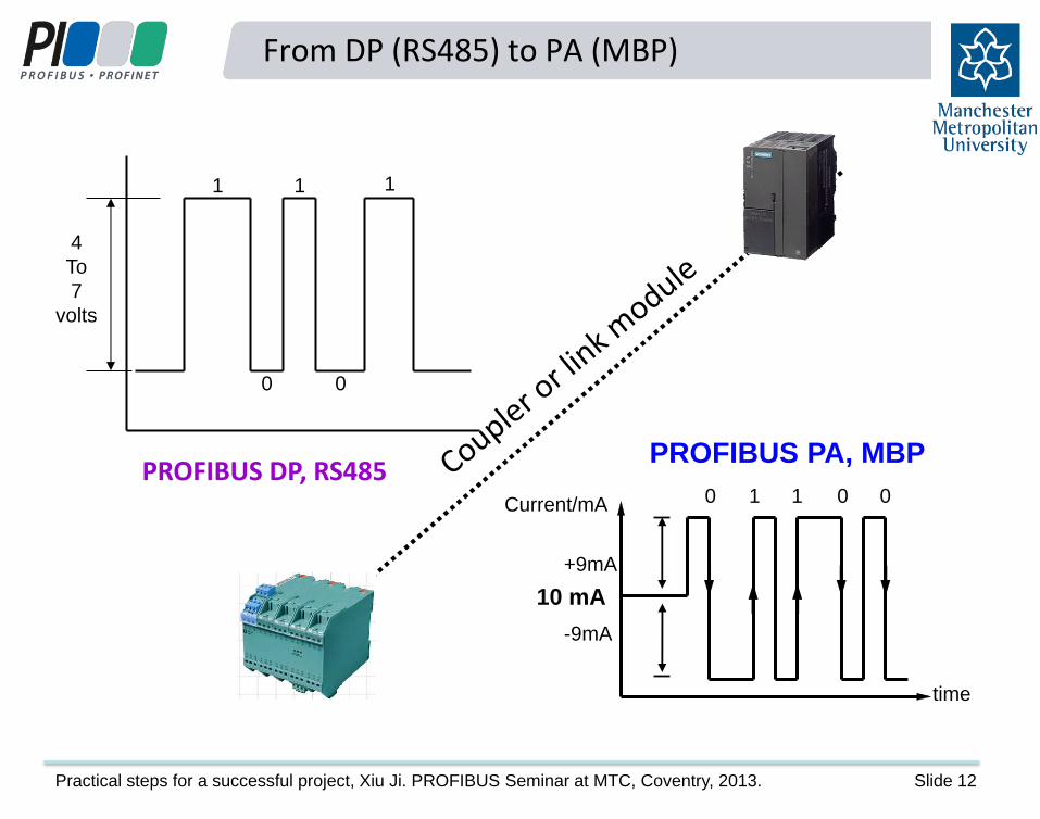
From DP (RS485) to PA (MBP)
0
-9mA
time
Current/mA
+9mA
1 1 0 0
PROFIBUS PA, MBP
10 mA
4
To
7
volts
PROFIBUS DP, RS485
0 0
1 1 1

Practical steps for a successful project, Xiu Ji. PROFIBUS Seminar at MTC, Coventry, 2013. Slide 13
DP & PA Segments
One PROFIBUS network can host up to 126 stations (masters and slaves) – capacity of a PROFIBUS DP master Limitation of RS485 and MBP – 32 loads and total cable length per segment
M
S
S S
S
S S
S
S
M
S
S
S
S
R O O
Segment 1
RS485
Segment 2
RS485
Segment 3
Fibre Optic
Segment 4
RS485
Segment 5
MBP
Repeater
Fibre optic
links
C
DP/PA
Coupler
S
Page 23

Practical steps for a successful project, Xiu Ji. PROFIBUS Seminar at MTC, Coventry, 2013. Slide 14
Segmentation, PA
The maximum number of devices on a PA segment is the same as the maximum on a DP segment, which is 32. However, how many slaves can be connected to a PA segment depends primarily on the power supplied to the segment.
Segment Coupler V = 13.4 VDC, I = 100 mA
#13 #14
#15
#16
#17
T
14 mA 14 mA 14 mA 14 mA 14 mA
Maximum number of PA slaves = 100 / 14 = 7
I actual = 5 x 14 = 70 mA
Practical steps for a successful project, Xiu Ji. PROFIBUS Seminar at MTC, Coventry, 2013. Slide 15
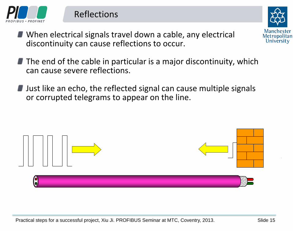
Reflections
When electrical signals travel down a cable, any electrical discontinuity can cause reflections to occur. The end of the cable in particular is a major discontinuity, which can cause severe reflections. Just like an echo, the reflected signal can cause multiple signals or corrupted telegrams to appear on the line.

Practical steps for a successful project, Xiu Ji. PROFIBUS Seminar at MTC, Coventry, 2013. Slide 16
Reflections

Practical steps for a successful project, Xiu Ji. PROFIBUS Seminar at MTC, Coventry, 2013. Slide 17
Termination - Rules
To avoid reflections from the ends of the cable it is essential that each segment is terminated at the two ends and nowhere else. Two terminators in each segment must be powered at all times.
Practical steps for a successful project, Xiu Ji. PROFIBUS Seminar at MTC, Coventry, 2013. Slide 18
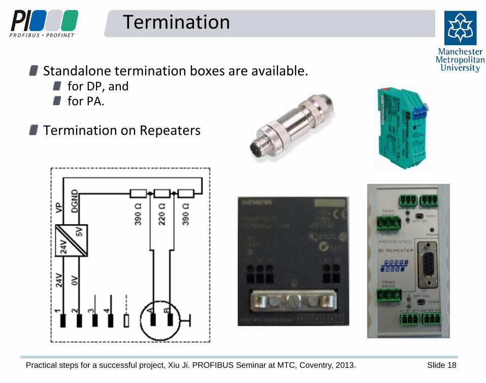
Termination
Standalone termination boxes are available. for DP, and for PA.
Termination on Repeaters

Practical steps for a successful project, Xiu Ji. PROFIBUS Seminar at MTC, Coventry, 2013. Slide 19
Termination
1 network with 2
segments.
DP/PA
coupler
#1 #0
#10 #11
#13 #14
#15
#16
#17
Power supply for PA segment
T T
T
T

Practical steps for a successful project, Xiu Ji. PROFIBUS Seminar at MTC, Coventry, 2013. Slide 20
Causes of Reflections
Missing terminator Un-powered terminator Terminator switch - faulty Extra terminator Reflection can also be caused by:
Un-certified devices. Cable length between two devices is too short. Spurs are used in high speed networks. Wrong types of cables are used. Cores are sharply bended.
Page 31

Practical steps for a successful project, Xiu Ji. PROFIBUS Seminar at MTC, Coventry, 2013. Slide 21
Interference
Interference is picked up from adjacent equipment or connected equipment with poor Electromagnetic Compatibility (EMC) rating. Interference can be caused by:
Inadequate earthing of equipment, Poor or incorrect earthing of cable shield, Insufficient segregation of power and bus cables, Routing cables through electrically noisy areas, and Heavy earth currents on the cable screen.
2
1

Practical steps for a successful project, Xiu Ji. PROFIBUS Seminar at MTC, Coventry, 2013. Slide 22
Equipotential Bonding

Practical steps for a successful project, Xiu Ji. PROFIBUS Seminar at MTC, Coventry, 2013. Slide 23
Shielding and Grounding
The recommended grounding practices:
Connect all PROFIBUS interfaces and cable shields to ground.
Use a grounding cable to go from cabinet to cabinet
in the same segment – equipotential bonding.
Types of grounding:
Direct grounding (at any connecting point)
Capacitive grounding
Installation: Shielding and Grounding 2
3 intern

Practical steps for a successful project, Xiu Ji. PROFIBUS Seminar at MTC, Coventry, 2013. Slide 24
Grounding of devices and shields
Connect the PROFIBUS cable shield to the equipotential bonding at every PROFIBUS station assuming local potentials are equal!
Shielded, twisted-pair cable
Cable shield route
to ground Rx
Tx Tx
Rx
Connector
Screw
terminals
Device Device
Red = +
Green = -

Practical steps for a successful project, Xiu Ji. PROFIBUS Seminar at MTC, Coventry, 2013. Slide 25
Wrong connectors
Which connectors are faulty?
A C B C
Practical steps for a successful project, Xiu Ji. PROFIBUS Seminar at MTC, Coventry, 2013. Slide 26
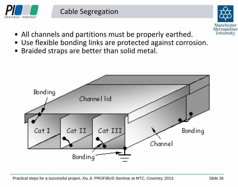
Cable Segregation
• All channels and partitions must be properly earthed. • Use flexible bonding links are protected against corrosion. • Braided straps are better than solid metal.

Practical steps for a successful project, Xiu Ji. PROFIBUS Seminar at MTC, Coventry, 2013. Slide 27
Cable Segregation Distance
In general, the greater the spacing between the cables and the shorter the paths run parallel, the lower the risks of interference. Recommended cable segregation distances:
Cable
Category II
20 cm
10 cm 10 cm
50 cm 50 cm
50 cm
Cable
Category I
Cable
Category III
Cable
Category IV

Practical steps for a successful project, Xiu Ji. PROFIBUS Seminar at MTC, Coventry, 2013. Slide 28
Cable Segregation ?
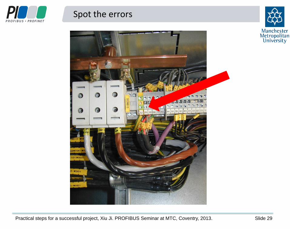
An example: frequent converters. Can you spot the error here?
Power able route
Practical steps for a successful project, Xiu Ji. PROFIBUS Seminar at MTC, Coventry, 2013. Slide 29
Spot the errors
Practical steps for a successful project, Xiu Ji. PROFIBUS Seminar at MTC, Coventry, 2013. Slide 30
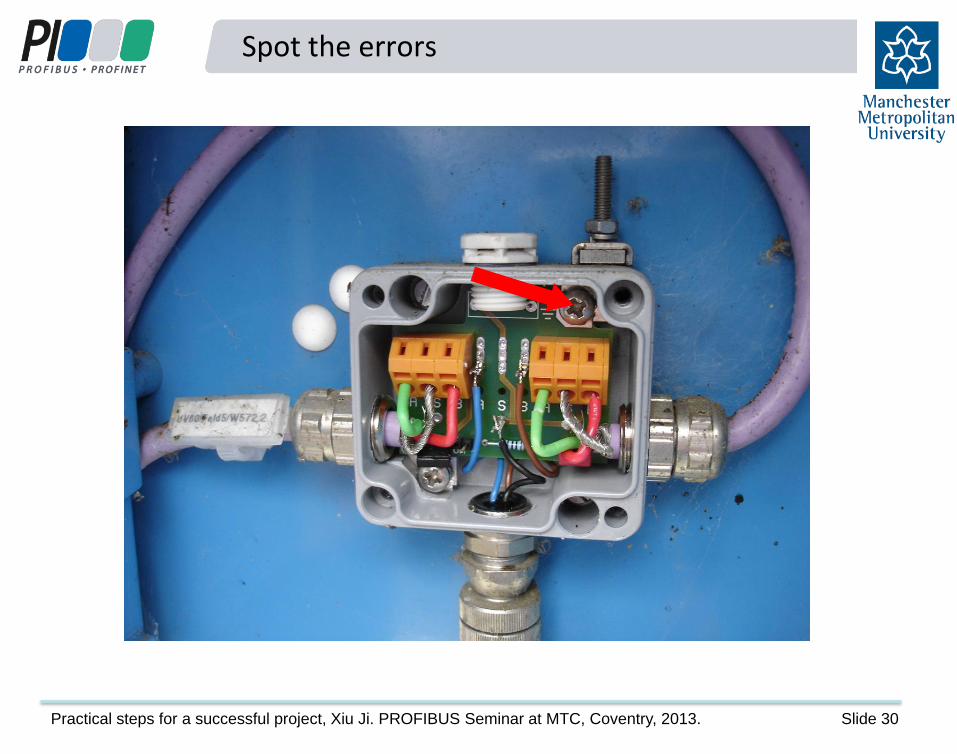
Spot the errors
Practical steps for a successful project, Xiu Ji. PROFIBUS Seminar at MTC, Coventry, 2013. Slide 31
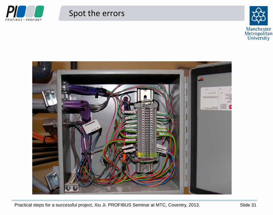
Spot the errors
Practical steps for a successful project, Xiu Ji. PROFIBUS Seminar at MTC, Coventry, 2013. Slide 32
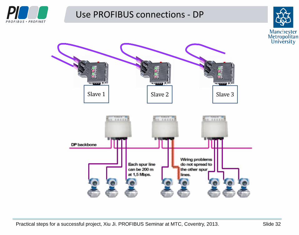
Use PROFIBUS connections - DP
3
2

Practical steps for a successful project, Xiu Ji. PROFIBUS Seminar at MTC, Coventry, 2013. Slide 33
Use PROFIBUS connections - PA
3
3
T Link/
Coupler T PROFIBUS DP PROFIBUS PA
Trunk
Spur lines
Devices
Link/
Coupler T PROFIBUS DP PROFIBUS PA T
Junction
Box
Junction
Box
Spur lines
Trunk
Devices

Practical steps for a successful project, Xiu Ji. PROFIBUS Seminar at MTC, Coventry, 2013. Slide 34
Spot the errors

Practical steps for a successful project, Xiu Ji. PROFIBUS Seminar at MTC, Coventry, 2013. Slide 35
Design considerations - details
Limitations of segment loads and total cable length Standalone terminations for DP, redundant power supply to terminators Network drawings – node addresses, position of termination, cable length between connectors and junction boxes, trunk cable and drop cable length Piggyback connectors – spare connection into EVERY segment for voltage measurements and troubleshooting

Practical steps for a successful project, Xiu Ji. PROFIBUS Seminar at MTC, Coventry, 2013. Slide 36
Design considerations - architecture
Which network to use – PROFIBUS, PROFINET, DP, PA, AS-i? Designation of safe and explosive areas Production and functional safety systems Cable routes – fibres, copper cables, earthing systems, equipotential bonding cable in place? Cabinet or field assembly Connection of devices via remote IO or integrated fieldbus? Use of redundancy at difference levels Network and device access for engineering, monitoring and maintenance Design documents and drawings
3
6

Practical steps for a successful project, Xiu Ji. PROFIBUS Seminar at MTC, Coventry, 2013. Slide 37
Installation Checklists
Checklist to determine network topology and obtain the network drawing Checklist for PROFIBUS DP (RS485) Grounding Checklist for PROFIBUS PA (MBP) Grounding Checklist for PROFIBUS DP (RS485) Cabling
3
7
Page 73

Practical steps for a successful project, Xiu Ji. PROFIBUS Seminar at MTC, Coventry, 2013. Slide 38
Practical steps to a successful PROFIBUS project
The very first step to a successful project should be
Training
PROFIBUS training courses are available for: Designers, Installers, Commissioning Engineers, and Maintenance staff.
Many industry sectors specify that their staff, contractors and sub contractors must be appropriately trained. PI Competence Centre - Manchester Metropolitan University, in-house or on-site training PI Training Centre – Verwer Training and Consultancy, on-site training for min. 6 people
3
8

Practical steps for a successful project, Xiu Ji. PROFIBUS Seminar at MTC, Coventry, 2013. Slide 39
Summary: Steps to a successfully project
1. Design staff should be trained before the design starts.
2. Everyone involved in the project at a technical level is trained to an adequate level, at the least to the designer or installer level.
3. Make sure that designers are fully aware of the methods for diagnosing and locating faults.
4. Ensure that health checking and performance monitoring facilities are incorporated into the network.
5. Follow the extensive guidance that is available from PI and from competency and training centres, for example, incorporating the checklists into your installation acceptance tests.
3
9
Reference (Page 79)