practical uml modeling with rational software architect · basic facts ibm rational software...
TRANSCRIPT

Practical UML Modeling with
Rational Software Architect

Basic Facts
IBM Rational Software Architect is the latest generation of Rational
Rose UML modeling tools
ROSE = Rational Object-oriented Software Engineering
First developed by James Rumbaugh, Ivar Jacobson, and Grady
Booch in Rational Software as part of efforts to support model-
based design for object-oriented languages.
These three guys proposed UML.
Rational Rose was introduced in OOPSLA’92 as the first UML-
based modeling tool.
Rational was acquired by IBM in December 2002 for 2.1 Billions.
Rational Rose and its successor IBM Rational Software Architect are
still the leading UML-based modeling tools by far.

Basic Facts
Rational Software Architect is an integrated visual modeling
tool for development of object-oriented software.
Rose uses UML to provide graphical methods for non-
programmers wanting to model business processes as well
as programmers modeling application logic.
Developed on the Eclipse platform.
Eclipse is a platform for building, deploying, and managing software
across the lifecycle.
The Eclipse platform encourages rapid development of integrated
features based on a plug-in model.
A wider range of plug-in is available, including the support for SVN.

Homework/project use
Rational Software Architect (RSA) has been installed on
all CS lab machine and ELEC.
To launch it, use “/cslab/bin/rational”
You can obtain a copy of RSA for use in senior design.
Full featured standard edition for Linux/Windows. Free of
charge. To obtain it,
Download the IBM academic license agreement form by following
the link in the course website;
Send me an email containing the following sentence: “I have read
and accepted IBM agreement for IBM academic initiative.”
Upon receiving your email, I will send you instruction to download
your copy.

UML: an overview

Why design matters

Requirement Modeling
Use-case diagram
Structural Modeling
Component diagram;Deployment diagram
OO modeling
Class diagram
BehavioralModeling
State diagram;Sequence diagram;Activity diagram;
Collaboration diagram
UML: 360°view of design

Platform-Independent
Model
Code-based Development
ITE
RA
TE
Requirements
Platform-Specific Model
Business Requirement:
• Textual requirement;
• Business analysis.
Application analysis:
• Component diagram;
• Deployment diagram.
Application use-cases:
• Use-case diagram.
Application design:
• Component diagram;
• Deployment diagram.
OO design:
• Class diagram.
UML: design workflow

UML Modeling with Software Architect
Rational Architect supports UML 2.0, including
the following diagrams,
Use-case diagram
Class diagram
State Diagram (StateChart)
Interaction Diagrams, including,
Sequence diagram
Collaboration diagram
Component Diagram
Deployment Diagram
…

Diagrams
Project
Component diagram
Class diagram
Elements
class
Component
Models
Palette for new
element
Property for selected
element
Component diagram

UML modeling with Software Architect:
examples

Software Architect: IDE
Software Architect uses a hierarchy to specify models.
Each session contains a workspace.
At the launch, software architecture will ask your workspace directory.
Among other things, it store your personal configuration for underlying
projects.
Each workspace contains multiple projects.
A project is the collection of models, or a case, you are working
on.
It can be located in a directory different from workspace
directory.
It can be shared by different workspace.
There is a variety way to incorporate a project into a workspace,
e.g., using existing project files, using CVS or SVN etc.

To activate this dialog, right click in
Project explorer, choose “import project”
Add existing project to a
workspace
Import project directly from a
SVN repository.

Software Architect: IDE
Each model may contain several UML diagrams to express
the different “views” of a model, for example,
A class diagram provides inheritance hierarchy and
associations among classes.
A component diagram provides the architect design.
Software architect supports diagrams defined in UML 2.0.
Each model may contain several elements, whose relations
are defined in diagrams.
RSA lists all the elements with their hierarchy in project
explorer for easy navigation of these elements.

Software Architect: IDE
Elements are part of “unified” model and they are
shared by different diagrams,
Sharing elements provide consistent among diagrams, for
example, a class in a class diagram can also be used to,
define an object in a sequence diagram.
This is very useful in a team development
environment, where different designers work on
different diagrams (and aspects) for the same model.
To maintain the consistency, you need to merge models
developed by different designers.

UML modeling with Software Architect:
examples

Class Diagram

Class Diagram
class
association
inheritanceProperties of classes and relations
can be customized using
Property view

Adding Elements
1Drag an existing element
from the Project
Explorer view.
+
2Click a tool in the diagram editor’s
tool palette and then click inside the
diagram.
Hover or click the mouse in the diagram to make the action bar appear. Select the
element to insert. Hover over the new model element to use the action bar to add
details (attributes and operations).3

Property of Class

Property of Class

Property of Class

Property of Association
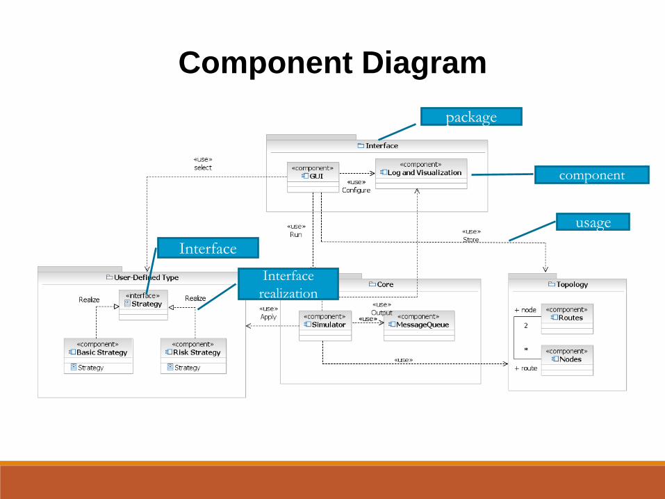
Component Diagram
package
component
usage
Interface
realization
Interface

Property Views

Property Views

RSA in action
Integration with software development process

Configuration Management (CM)
CM allows change in software assets to occur in a structured, controlled, and repeatable fashion.
A CM tool can:
Give team members simultaneous access to models
Control who can update different model elements
Help introduce changes in a controlled manner
Maintain the evolutionary history of a model and its elements
A CM process defines how tools will be used to manage change in a project.
We use SVN for CM.
Business.emx src
Repository

SCM Best Practices: Model Partitioning
Partition a model to avoid
unnecessary merges
Factors to consider when deciding
how to partition a model:
Stabilize abstraction levels
Minimize dependencies
between models
Establish ownership policies
Avoid broken references

To manage partitions, you can:
Create fragments
An element that has been converted into a fragment has this icon:
Create new models from packages
A package that has been made into a model has this icon:
Absorb fragments back into the model
Copy packages from partitions
back into the main model
Model Partitioning
Creating a model from a package automatically leaves a
shortcut reference to the new model where the package used
to be.
Creating a fragment from a model element adds an adornment to the
element and creates a separate file for that element.

Partition and Fragment Files
After you have created a partition and a
fragment, Rational Software Architect will
create new files to represent these elements.
You can view all of the files in the Navigator
view.
Design Model.emx is the original model
that you started with.
you have two fragments that have been
created in relationship to this model. So
you have two .efx files within your project.
In addition, you specified that
you wanted to convert the
presentation package into its
own model. So there is another
.emx file.
Don’t forget to add and commit your newly created
files to SVN.
Right-click the file, choose team/add to version
control, and then commit.

Compare and Merge Models
In a typical team environment, team members need to
constantly merge their development work to a common code
base. True to designs as well. Merging is almost always inevitable in a team development environment,
Rational Software Architect allows you to merge model and
diagram files using the compare and merge utility. Compare models to identify changes between model versions.
Merge models when:
Parallel development occurs
Alternative approaches are explored
Use wisely: avoid situations that require frequent merging. Merge is expensive: think about how much self-inflicted pains you and your
team may have when you have to solve merge confliction.
Fragmenting your model wisely to avoid unnecessary mergers.

Compare Editor
Structural Differences
•Accept or Reject changesMerged Model
Right ContributorLeft Contributor

Merging Models
Begin with a base
contributor, the common
ancestor of the models
you wish to merge.
Have up to three
contributors (modified
versions of the base
model) in a merge session.
2
3
4
5
Contributor 1
Base
Contributor
Contributor 2
1
Merge

Structural Differences
•Accept or Reject changesMerged result
Left Contributor Right ContributorAncestor
Caution: always remember to save a
copy, then override the existing file, and
submit to SVN.
RSA will not commit changes
automatically to SVN!