practice workbook - squarespace workbook this workbook is designed for use in live instructor-led...
TRANSCRIPT

Practice WorkbookThis workbook is designed for use in Live instructor-led training and for OnDemand selfstudy. The explanations and demonstrations are provided by the instructor in the classroom, or in the OnDemand eLectures of this course available on the Bentley LEARN Server (learn.bentley.com).
This practice workbook is formatted for on-screen viewing using a PDF reader. It is also available as a PDF document in the dataset for this course.
DO NOT DISTRIBUTE - Printing for student use is permitted
Overlay, Stripping, and WideningExercise 1: Creating an Overlay Template
Exercise 2: Creating a Stripping or Milling Template
Exercise 3: Evaluating the Cost of a Corridor
Exercise 4: Creating a Multi-Layer Overlay Template
Exercise 5: Creating a Widening Template
Exercise 6: Vertical Adjustments - Milling
Exercise 7: Vertical Adjustments - Overlay
TRNC01894-1/0001

Copyright © 2015 Bentley Systems, Incorporated 2DO NOT DISTRIBUTE - Printing for student use is permitted
Description and Skills Taught
Course DescriptionThis workbook contains steps to utilize overlay and stripping components within corridor templates and covers how to use them along with the vertical adjustment tools to evaluate the most cost effective solution.
Skills Taught Creating Overlay and Stripping Components
Incorporating Overlay and Stripping into Roadway Templates
Calculating Corridor Component Quantities

Getting Started
This course is appropriate for any of the Bentley Civil software applications powered by OpenRoads Technology including...
Power GEOPAK or GEOPAK
Power InRoads or InRoads
Bentley MXROAD
PowerCivil for {country}
Dataset UnitsBoth Imperial and Metric versions of the dataset are available. Throughout this practice workbook Imperial values are specified first and the metric values second. The metric values are enclosed in square brackets. For example: 12’ [3.4m]
Training Workspace - IMPORTANT!This OpenRoads training course uses a specific “training” workspace. The workspace includes the necessary standards including feature definitions, design standards, civil cells, and more.
The workspace can be downloaded from the link below:
http://webedocprdsa01.blob.core.windows.net/datasets/civil_training_workspace.zip
Please download the training workspace (approx. 70 MB) from the link above BEFORE your training class.
We recommend you save the “Civil Training Workspace” to C:\Bentley Training\. However, if this isn’t possible, you can save it to another location.

Copyright © 2015 Bentley Systems, Incorporated 4DO NOT DISTRIBUTE - Printing for student use is permitted
Setting Up the Training Workspace (MXROAD users skip to the next section)
In this section, you will start the software and create a new user to utilize the training workspace. Selecting the proper workspace is very important within OpenRoads. This workspace contains the civil standards you need to complete the training exercises.
1. If the Civil Training Workspace is already installed, open the software as the Civil_Training and skip to Exercise 1, otherwise continue and follow the steps below.
2. Download and install the workspace as directed in the READ ME.pdf file included with the dataset.
3. Start the GEOPAK, InRoads, Power GEOPAK, Power InRoads, or PowerCivil software.
4. Create a new User Configuration File
a. On the File Open window, click the drop-down menu for the User.
b. If Civil_Training already exists: Select the Civil_Training and skip to Exercise 1.
c. If Civil_Training does NOT exist: Select New.

Copyright © 2015 Bentley Systems, Incorporated 5DO NOT DISTRIBUTE - Printing for student use is permitted
d. Key in Civil_Training within the Name field and click OK.
Another dialog box opens.
e. Define the Project location by clicking the Select button.
f. Browse to C:\Bentley Training\Civil Training Workspace\ or to the location where you saved the training workspace.
g. Select the appropriate Project Configuration File - Bentley-Civil-Imperial-Training.pcf [Bentley-Civil-Metric-Training.pcf]
h. Click Open to select the .pcf file
i. Click OK to create the new user configuration file.
5. On the File Open window, define the workspace settings as shown.
User: Civil_Training
Project: Bentley-Civil-Imperial-Training or [Bentley-Civil-Metric-Training]
Interface: Bentley-Civil
6. Skip to Exercise 1.

Copyright © 2015 Bentley Systems, Incorporated 6DO NOT DISTRIBUTE - Printing for student use is permitted
Start the MXROAD Software with a Workspace (For MXROAD users ONLY, others skip to the next section)
In this section, you will start the software and create a new user to utilize the training workspace. Selecting the proper workspace is very important within OpenRoads. This workspace contains the civil standards you need to complete the training exercises.
1. Unzip from the Training data set the Civil Training Workspace to C:\Bentley Training\...
2. Browse to the Civil Training Workspace User Configuration folder C:\Bentley Training\Civil Training Workspace\User-Configuration
3. Open the Civil_Training_Imperial.ucf [Civil_Training_Metric.ucf] file and ensure that the ’_USTN_PROJECT ‘ variable is set to the location where you installed the Civil_Training_Workspace. In this example, C:\Bentley Training\Civil Training Workspace.
4. Copy the Civil_Training_Imperial.ucf [Civil_Training_Metric.ucf] User Configuration file to the default Bentley MXROAD installation location depending upon the computer operating system…
For Windows XP: \Documents and Settings\All Users\Application Data\Bentley\MX V8i (SELECT Series 3)\Workspace\Users...
For Windows Vista or newer: \ProgramData\Bentley\ MX V8i (SELECT Series 3)\Workspace\Users...
5. Start the Bentley MXROAD software.
6. If the ‘Tip of the Day’ window appears, click OK to close the window.
7. On the MX Project Start Up window...

Copyright © 2015 Bentley Systems, Incorporated 7DO NOT DISTRIBUTE - Printing for student use is permitted
a. Click New Project and in the MX Project Start Up window define the MicroStation Settings as shown.
User: Civil_Training_Imperial [Civil_Training_Metric]
Project: Bentley-Civil-Imperial-Training [Bentley-Civil-Metric-Training]
Interface: Bentley-Civil
b. Click Browse and select the folder where the training dataset is located.
c. Key in Training in the Project Name field.
d. Click Make New Folder and name the new folder MX Project.
e. Click OK to accept the ...\MX Project\ folder.
f. Set the Default MX Project Settings to UK_imperial [UK_metric].
g. Click OK.
The MX project files are created and the software opens into a blank file named draw.dgn.
8. Skip to Exercise 1.

Copyright © 2015 Bentley Systems, Incorporated 8DO NOT DISTRIBUTE - Printing for student use is permitted
Tools used in the Overlay and Stripping Workflow
Many construction projects today are rehabilitation projects requiring overlay, stripping, and/or widening. The Roadway Designer Overlay Tools provide the ability to better streamline the process and easily try different scenarios to minimize cost.
There are two tool sets in OpenRoads that are used for overlay solutions:
Overlay/Stripping Components
Vertical Adjustments
Template components and vertical adjustments are relatively independent of one another in the software, they are tightly related in providing a valid engineering solution.
Quantities are calculated from template components; Overlay/Stripping components are obligatory for accurate quantities.
Vertical Adjustments are used to calculate, define and refine a vertical alignment that optimally meets the design or cost criteria.
Overlay and Stripping ComponentsOverlay and Stripping Components are different from other template components in that they are not limited to simple geometric constraints. Overlay and stripping component edges can follow a surface.
Two end results of creating Corridors with Overlay/Stripping Components is detailed Cross Sections and accurate component End Area Volumes. Overlay/ Stripping components behave identically whether the Corridor Vertical Control is a defined Vertical Alignment or “live” Vertical Adjustment settings. If running from the Vertical Adjustment tool, those settings must be set properly and ultimately archived as an alignment for reuse.
Overlay and Stripping Components are not limited to use in road rehabilitation applications. Other uses include Vegetative Stripping and excavation quantities.
Vertical AdjustmentsVertical Adjustments read the top of the template and the existing ground to move the template vertically to optimize the amount of overlay and stripping.
The Adjustment methodology pays no attention to the types of components making up the template. The adjustments are identical regardless of whether Overlay or Stripping components are used. Proper quantities, however, do require Overlay and Stripping components.

Copyright © 2015 Bentley Systems, Incorporated 9DO NOT DISTRIBUTE - Printing for student use is permitted
Exercise 1: Creating an Overlay Template
DescriptionIn this exercise you will learn how to create and use a template that incorporates an overlay component
Skills Taught Creating a template with an overlay component
Copyright © 2015 Bentley Systems, Incorporated 10DO NOT DISTRIBUTE - Printing for student use is permitted
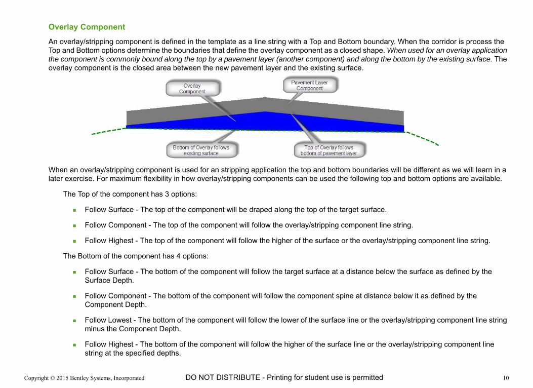
Overlay ComponentAn overlay/stripping component is defined in the template as a line string with a Top and Bottom boundary. When the corridor is process the Top and Bottom options determine the boundaries that define the overlay component as a closed shape. When used for an overlay application the component is commonly bound along the top by a pavement layer (another component) and along the bottom by the existing surface. The overlay component is the closed area between the new pavement layer and the existing surface.
When an overlay/stripping component is used for an stripping application the top and bottom boundaries will be different as we will learn in a later exercise. For maximum flexibility in how overlay/stripping components can be used the following top and bottom options are available.
The Top of the component has 3 options:
Follow Surface - The top of the component will be draped along the top of the target surface.
Follow Component - The top of the component will follow the overlay/stripping component line string.
Follow Highest - The top of the component will follow the higher of the surface or the overlay/stripping component line string.
The Bottom of the component has 4 options:
Follow Surface - The bottom of the component will follow the target surface at a distance below the surface as defined by the Surface Depth.
Follow Component - The bottom of the component will follow the component spine at distance below it as defined by the Component Depth.
Follow Lowest - The bottom of the component will follow the lower of the surface line or the overlay/stripping component line string minus the Component Depth.
Follow Highest - The bottom of the component will follow the higher of the surface line or the overlay/stripping component line string at the specified depths.
Copyright © 2015 Bentley Systems, Incorporated 11DO NOT DISTRIBUTE - Printing for student use is permitted
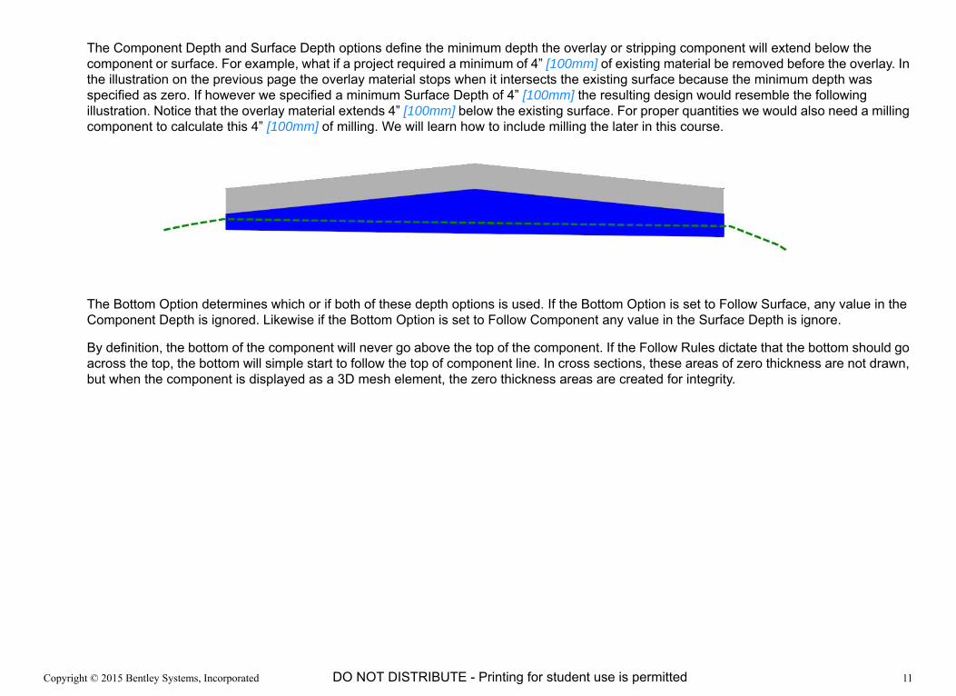
The Component Depth and Surface Depth options define the minimum depth the overlay or stripping component will extend below the component or surface. For example, what if a project required a minimum of 4” [100mm] of existing material be removed before the overlay. In the illustration on the previous page the overlay material stops when it intersects the existing surface because the minimum depth was specified as zero. If however we specified a minimum Surface Depth of 4” [100mm] the resulting design would resemble the following illustration. Notice that the overlay material extends 4” [100mm] below the existing surface. For proper quantities we would also need a milling component to calculate this 4” [100mm] of milling. We will learn how to include milling the later in this course.
The Bottom Option determines which or if both of these depth options is used. If the Bottom Option is set to Follow Surface, any value in the Component Depth is ignored. Likewise if the Bottom Option is set to Follow Component any value in the Surface Depth is ignore.
By definition, the bottom of the component will never go above the top of the component. If the Follow Rules dictate that the bottom should go across the top, the bottom will simple start to follow the top of component line. In cross sections, these areas of zero thickness are not drawn, but when the component is displayed as a 3D mesh element, the zero thickness areas are created for integrity.

Copyright © 2015 Bentley Systems, Incorporated 12DO NOT DISTRIBUTE - Printing for student use is permitted
Create an Overlay Template
1. Browse to the folder where you unzipped the dataset files and select the file Overlay and Stripping ‐ Templates.dgn [Overlay and Stripping - Templates-Metric.dgn].
The geometry and terrain are already referenced into this drawing.
2. If prompted that Obsolete Civil Data is Found, click Yes to upgrade the data in the file.
3. Open the Create Template tool from the Corridor Modeling task menu.
4. Open the Overlay Template Library.
5. Create a new template named Overlay Only.
6. Open the Dynamic Settings window.
7. Right-click in the Current Template view, then select Add New Component > Overlay/Stripping.

Copyright © 2015 Bentley Systems, Incorporated 13DO NOT DISTRIBUTE - Printing for student use is permitted
8. Set the following values in the Component Properties.
Name: Overlay
Feature: Overlay_Leveling
Top Option: Follow Component
Bottom Option: Follow Surface
Component Depth: 0.00
Surface: <Active>
Surface Depth: 0.00
9. Set a point at xy=‐12,‐0.24 [xy=-3.6,-0.072]
10. Set a point at xy=0,0
11. Set a point at xy=12,‐0.24 [xy=3.6,-0.072]
12. Right Click - Then select Finish.
13. Test the Overlay_Only template.
Notice the overlay area is computed from the between the overlay/stripping component on the top and the surface on the bottom.
14. Save the Template Library.
15. Close the Create Template window.

Copyright © 2015 Bentley Systems, Incorporated 14DO NOT DISTRIBUTE - Printing for student use is permitted
Create and Review an “Overlay Only” Corridor
An Overlay/Stripping component will stop where it intersects the bottom boundary such as the existing surface. This can result in an overlay that is less than the full width of the template. In the image below the right side is truncated before the full 12 foot width.
The exercise dgn file is setup with three views for your convenience. Starting in the upper left and moving clockwise the views show the plan, profile, and cross section.
1. Create a corridor with the following values using the Highway alignment (red line) in view 1.
Corridor Name: Overlay Testing
Profile Element: Active Profile
Template: Overlay Only
Start Station: Press ALT to lock to the beginning
End Station: Press ALT to lock to the end
Interval: 10
Start Transition: 0
Stop Transition: 0

Copyright © 2015 Bentley Systems, Incorporated 15DO NOT DISTRIBUTE - Printing for student use is permitted
Review the Results in the Corridor
To review the results, we will create dynamic cross sections of the corridor.
1. Select the Element Selection tool.
2. Select the corridor border.
Hint: It is easiest to select the corridor border by one of the lines that extends perpendicular to the border.
3. Select the Open Cross Section Model tool.
4. Place the cross section model in View 3.
5. Select the down arrow next to View Properties at the top of the window.
6. Set the Vertical Exaggeration to 5.
7. Click the left and right arrow icons at the top of the window to scroll through the cross sections. A light blue line in the plan view indicates the location of the cross section currently being displayed.
Note that the component width of the proposed solution varies depending on the geometry and surface at each station.

Copyright © 2015 Bentley Systems, Incorporated 16DO NOT DISTRIBUTE - Printing for student use is permitted
Modify the Overlay Template
To force the Overlay/Stripping component to provide design and calculations to the full width of the template we will also include a pavement component in the template.
1. Select the Create Template tool.
2. Right-click on the Simple Pavement template and select Copy.
3. Paste the new template into the root of the template library by right-clicking on the Overlay.itl name and then selecting Paste.
4. Right-click on the new Simple Pavement1 template and select Rename.
5. Rename the new template to Pave+Overlay.
6. Double-click the Pave+Overlay template to make it active.
7. With the Pave+Overlay template active, drag the Overlay Only template into it and drop it at the bottom of the pavement layer. Make sure the overlay points merge with the points defining the bottom of the pavement layer.
8. Test the new Pave+Overlay template.
The overlay component behaves just as it did before but the template now also has a fixed pavement layer.
9. Close the Test dialog.
10. Save the Template Library.
11. Close the Create Template window.

Copyright © 2015 Bentley Systems, Incorporated 17DO NOT DISTRIBUTE - Printing for student use is permitted
Review the Results in the Corridor
We will replace the Overlay_Only template with the new Pave+Overlay template within the corridor.
1. Select the Element Selection tool.
2. Select the Template Drop Handle for the corridor. The Template Drop Handle is on the left (looking up station) at the beginning of the corridor.
3. Select the Properties button from the context menu.
4. Change the corridor’s template from Overlay_Only to Pave+Overlay.
The corridor is automatically reprocessed using the new template and the dynamic cross sections updated.
Copyright © 2015 Bentley Systems, Incorporated 18DO NOT DISTRIBUTE - Printing for student use is permitted
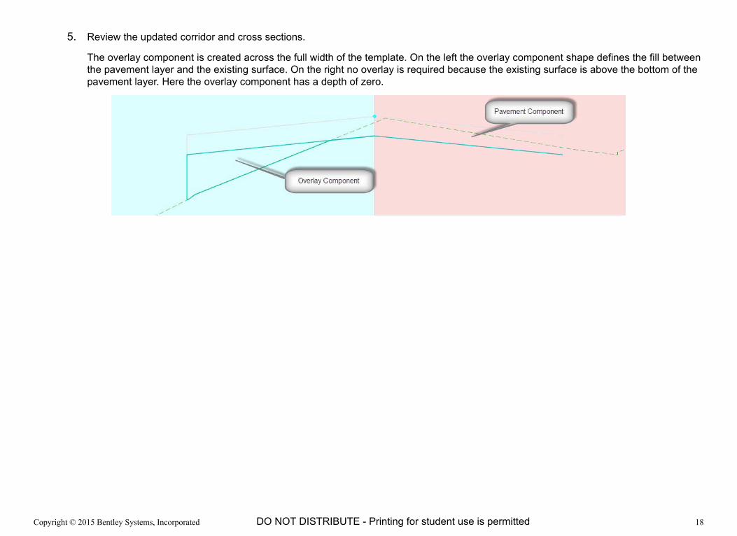
5. Review the updated corridor and cross sections.
The overlay component is created across the full width of the template. On the left the overlay component shape defines the fill between the pavement layer and the existing surface. On the right no overlay is required because the existing surface is above the bottom of the pavement layer. Here the overlay component has a depth of zero.
Copyright © 2015 Bentley Systems, Incorporated 19DO NOT DISTRIBUTE - Printing for student use is permitted
Exercise 2: Creating a Stripping or Milling Template
DescriptionIn this exercise you will learn how to create and utilize a template that incorporates a stripping component
Skills Taught Creating a template with a stripping component

Copyright © 2015 Bentley Systems, Incorporated 20DO NOT DISTRIBUTE - Printing for student use is permitted
Stripping ComponentThere is really no difference between an overlay and an stripping component in OpenRoads. The difference is how the Top and Bottom boundaries are defined. For an overlay application we learned to bound along the top by a pavement layer (another component) and along the bottom by the existing surface. For a stripping or milling application the boundaries will be reversed. The top boundary will typically be the existing surface and the bottom the overlay/stripping component line string.
The following illustration shows a stripping component (purple)
The Stripping Component check box defines that the volume from the component is included in the Milling Report.

Copyright © 2015 Bentley Systems, Incorporated 21DO NOT DISTRIBUTE - Printing for student use is permitted
Create a Stripping or Milling Template
1. Open the Overlay Template Library.
2. Copy the Simple Pavement template to a new template named Pave+Mill.
3. Double-click the Pave+Mill template to make it active.
4. Add the Milling component
a. Right-click in the Template view, select Add New Component > Overlay/Stripping.
b. Set the following values in the Component Properties.
Name: Milling
Feature: Overlay_Milling
Top Option: Follow Surface
Bottom Option: Follow Component
Component Depth: 0.00
Surface: <Active>
Surface Depth: 0.00
Stripping Component check box: Enabled
5. Create the milling component along the bottom of the pavement component. Set the points at the three bottom points.
6. Test the Pave+Mill template.
The milling component is bound by the active surface on the top and the bottom of the Milling component line string on the bottom.
7. Save the template and close the Create Template window.

Copyright © 2015 Bentley Systems, Incorporated 22DO NOT DISTRIBUTE - Printing for student use is permitted
Review the Results in the Corridor
Replace the Pave+Overlay template with the new Pave+Mill template within the corridor.
1. Change the template assigned to the corridor from Pave+Overlay to Pave+Mill.
a. Select the Element Selection tool.
b. Select the Template Drop Handle for the corridor. The Template Drop Handle is on the left (looking up station) at the beginning of the corridor.
c. Select the Properties button from the context menu.
d. Set the Template Name to Pave+Mill.
2. Review the updated corridor and cross sections.
The stripping component is created across the full width of the template. On the right the stripping component shape defines the milling between the bottom of the pavement layer and the existing surface which is very near the top of the proposed pavement layer. On the left no stripping is required because the existing surface is below the bottom of the pavement layer. Here the stripping component has a depth of zero.

Copyright © 2015 Bentley Systems, Incorporated 23DO NOT DISTRIBUTE - Printing for student use is permitted
Create an Overlay and Milling Template
1. Open the Overlay template library.
2. Copy the Pave+Overlay template to a new template named Pave+Overlay+Mill.
3. Double-click the Pave+Overlay+Mill template to make it active.
4. Add the Milling component
a. Right-click in the Template view, select Add New Component > Overlay/Stripping.
b. Set the following values in the Component Properties.
Name: Milling
Feature: Overlay_Milling
Top Option: Follow Surface
Bottom Option: Follow Component
Component Depth: 0.00
Surface: <Active>
Surface Depth: 0.00
Stripping Component check box: Enabled
5. Create the milling component along the bottom of the pavement component. Set the points at the three bottom points
6. Test the Pave+Overlay+Mill template.
Both stripping and overlay components should be functioning in the template.
7. Save and close the Template Library.
Copyright © 2015 Bentley Systems, Incorporated 24DO NOT DISTRIBUTE - Printing for student use is permitted
Review the Results in the Corridor
We will replace the Pave+Mill template with the new Pave+Overlay+Mill template within the corridor.
1. Change the template assigned to the corridor from Pave+Mill to Pave+Overlay+Mill.
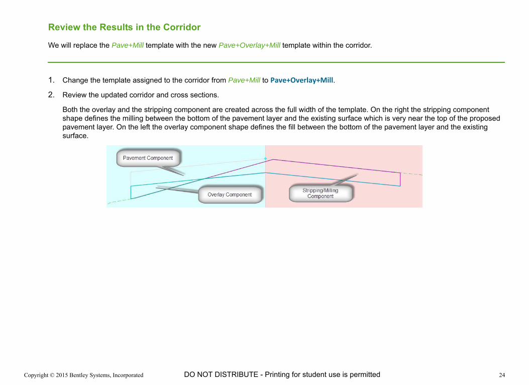
2. Review the updated corridor and cross sections.
Both the overlay and the stripping component are created across the full width of the template. On the right the stripping component shape defines the milling between the bottom of the pavement layer and the existing surface which is very near the top of the proposed pavement layer. On the left the overlay component shape defines the fill between the bottom of the pavement layer and the existing surface.

Copyright © 2015 Bentley Systems, Incorporated 25DO NOT DISTRIBUTE - Printing for student use is permitted
Exercise 3: Evaluating the Cost of a Corridor
DescriptionIn this exercise we will compute component quantities to evaluate the corridor’s cost.
Skills Taught Compute the component quantities along a corridor.

Copyright © 2015 Bentley Systems, Incorporated 26DO NOT DISTRIBUTE - Printing for student use is permitted
Corridor Component Quantities
The Corridor Components Quantities tool provides volume totals of closed-shape components and area totals of open components.
All Materials have a user-definable Unit Cost field. When non-zero, a running cost is tabulated.
It should be emphasized that the purpose of this tool is not to provide the full capability and accuracy of the Cross Section-based End Area Volumes reports. This tool provides reasonable quantity estimates quickly for making engineering decisions such as evaluating the effects of changing overlay and milling depths.

Copyright © 2015 Bentley Systems, Incorporated 27DO NOT DISTRIBUTE - Printing for student use is permitted
Review Component Quantities
1. Select the Element Selection tool.
2. Select the corridor border.
3. Select the Corridor Reports tool.
4. From the drop-down menu, select Corridor Component Quantities.
The Component Quantities dialog opens. Notice the quantity Material is defined by the component feature definition.

Copyright © 2015 Bentley Systems, Incorporated 28DO NOT DISTRIBUTE - Printing for student use is permitted
Generate a Cost Based Quantities Report
1. Set the Unit Cost for the Overlay_Leveling material to 32.5 [350.00]
2. Set the Unit Cost for the Overlay_Milling material to 2.78 [98.18]
3. Note the Total Estimated Cost.
A note on how the cost of milling was derived: Milling is often quoted by area milled rather than volume milled. Given a quote per square yard or square foot, we can convert to an approximate cost per unit of volume if we can assume an average depth. Reviewing the milling on the Original surface, most of the milling areas (in section) are triangular wedges. The average depth of these wedges will be one half the maximum milling. Given a maximum milling depth of 0.2 [0.1], gives us an average milling depth of 0.1 [0.05]. Converting a quote of $2.50/square yard results in a unit volume cost of $2.78/ft3 [$98.18/m3] ($2.50/cy / 9sf/sy / 0.1 = $2.78/ft3).
4. Click the Report button.
The Bentley Civil Report Browser opens.
5. Select the CorridorModeling > Corridor Model Component Quantities.xsl style sheet.
6. Review the report.
7. Close the Report Browser.
8. Close the Component Quantities window.
9. Make note or write down the Total Estimated Cost for the current solution using the Existing profile.
10. Close the Component Quantities window.

Copyright © 2015 Bentley Systems, Incorporated 29DO NOT DISTRIBUTE - Printing for student use is permitted
Finding a Cost Effective Solution
Changing the profile will affect the amount of overlay leveling and milling required on the project which in turn affects the total estimated cost.
1. Change the active profile of the corridor to Alternate 1.
a. Select the Element Selection tool.
b. Select the corridor border.
c. Select the Properties button from the context menu.
d. Set Use Active Profile to False.
e. Set the Profile Name to Alternate 1.
The corridor is reprocessed automatically. The model and dynamic cross sections are updated to the new corridor.
2. Select the Corridor Component Quantities tool.
3. Review the Total Estimated Cost and note the amount for this solution using the Alternate 1 profile.
The Alternate 1 profile is three inches lower than the Existing profile.
4. Change the active profile of the corridor to Alternate 2.
5. Select the Corridor Component Quantities tool.
6. Review the Total Estimated Cost and note the amount for this solution using the Alternate 1 profile.
The Alternate 2 profile is three inches higher than the Existing profile.
7. Which profile results in the most cost effective solution?
Copyright © 2015 Bentley Systems, Incorporated 30DO NOT DISTRIBUTE - Printing for student use is permitted
Milling Report
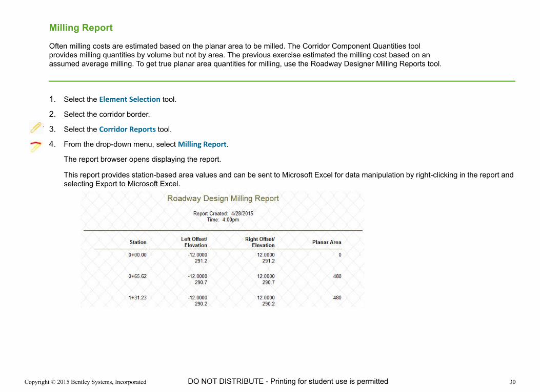
Often milling costs are estimated based on the planar area to be milled. The Corridor Component Quantities tool provides milling quantities by volume but not by area. The previous exercise estimated the milling cost based on an assumed average milling. To get true planar area quantities for milling, use the Roadway Designer Milling Reports tool.
1. Select the Element Selection tool.
2. Select the corridor border.
3. Select the Corridor Reports tool.
4. From the drop-down menu, select Milling Report.
The report browser opens displaying the report.
This report provides station-based area values and can be sent to Microsoft Excel for data manipulation by right-clicking in the report and selecting Export to Microsoft Excel.
Copyright © 2015 Bentley Systems, Incorporated 31DO NOT DISTRIBUTE - Printing for student use is permitted
Exercise 4: Creating a Multi-Layer Overlay Template
DescriptionIn this exercise we will create and utilize a template with multiple overlay layers within a single project. Multiple overlay layers are useful when different materials are required for structural integrity or cost effectiveness. Money can be saved on deep overlays, by setting a maximum depth for a premium overlay layer and filling any additional overlay with a cheaper binder.
Skills Taught Creating a template that contains multiple overlay components.

Copyright © 2015 Bentley Systems, Incorporated 32DO NOT DISTRIBUTE - Printing for student use is permitted
Build the Maximum-Depth Layer
1. Open the Overlay Template Library.
2. Copy the Simple Pavement template to a new template named Multi‐Layer Overlay.
3. Double-click the Multi‐Layer Overlay template to make it active.
4. Right-click in the Template view, select Add New Component > Overlay/Stripping.
5. Set the following values in the Component Properties.
Name: Premium Overlay
Feature: Overlay_Leveling
Top Option: Follow Component
Bottom Option: Follow Highest
In the previous exercises the bottom of the overlay followed the existing surface. The bottom if this Premium Overlay component will be 0.33ft [0.1m] (defined by the Component Depth) deep or until it intersects the existing surface is higher. The result is a premium overlay layer that is never thicker than 0.33ft [0.1m].
Component Depth: 0.333 [0.1]
Surface: <Active>
Surface Depth: 0.00

Copyright © 2015 Bentley Systems, Incorporated 33DO NOT DISTRIBUTE - Printing for student use is permitted
6. Set the points coincident with the L_EOP_Bot, PGL_Bot, and R_EOP_Bot points.
7. Test the template.
Hint: Set the Surface Slope to 3.0% to see the effect of a sloped existing surface.
Recognize that the overlay component follows the higher of the component bottom and the existing ground across the template. On the left edge of the illustration above the surface is below the 0.33ft [0.1m] component depth so the overlay stops at the component. Across most of the rest of the section the surface is higher than the component and defines the bottom of the overlay shape.
8. Close the Test End Conditions window.

Copyright © 2015 Bentley Systems, Incorporated 34DO NOT DISTRIBUTE - Printing for student use is permitted
Build the Economic Bottom Overlay Layer
1. Right-click in the template view, select Add New Component > Overlay/Stripping.
2. Set the following values in the Component Properties.
Name: Economy Overlay
Feature: Overlay_Binder
Top Option: Follow Component
Bottom Option: Follow Surface
The top of this overlay component is bound by the bottom of the Premium Overlay and the bottom is bound by the existing surface. There is no limit on the depth of the overlay.
Component Depth: 0.0
Surface: <Active>
Surface Depth: 0.0
3. Set the points near bottom points of the Premium Overlay component.
Note that the bottom of the Overlay component does not actually have any points to snap to. Just get close in this step. We will adjust the points to their accurate position next.
4. Constrain the new points to 4“ [0.1m] below the L_EOP_Bot, PGL_Bot, and R_EOP_Bot points.
a. Vertical Constraint: 0.333 [0.1]
b. Horizontal Constraint: 0

Copyright © 2015 Bentley Systems, Incorporated 35DO NOT DISTRIBUTE - Printing for student use is permitted
5. Test the template.
When overlay is required, the premium layer (blue) is created for a maximum depth of 0.333 ft [0.1 m]. The economic binder layer is then created for any additional fill depth that is required.
Copyright © 2015 Bentley Systems, Incorporated 36DO NOT DISTRIBUTE - Printing for student use is permitted
Build the Milling Layer
1. Right-click in the Template view, select Add New Component > Overlay/Stripping.
2. Set the following values in the Component Properties.
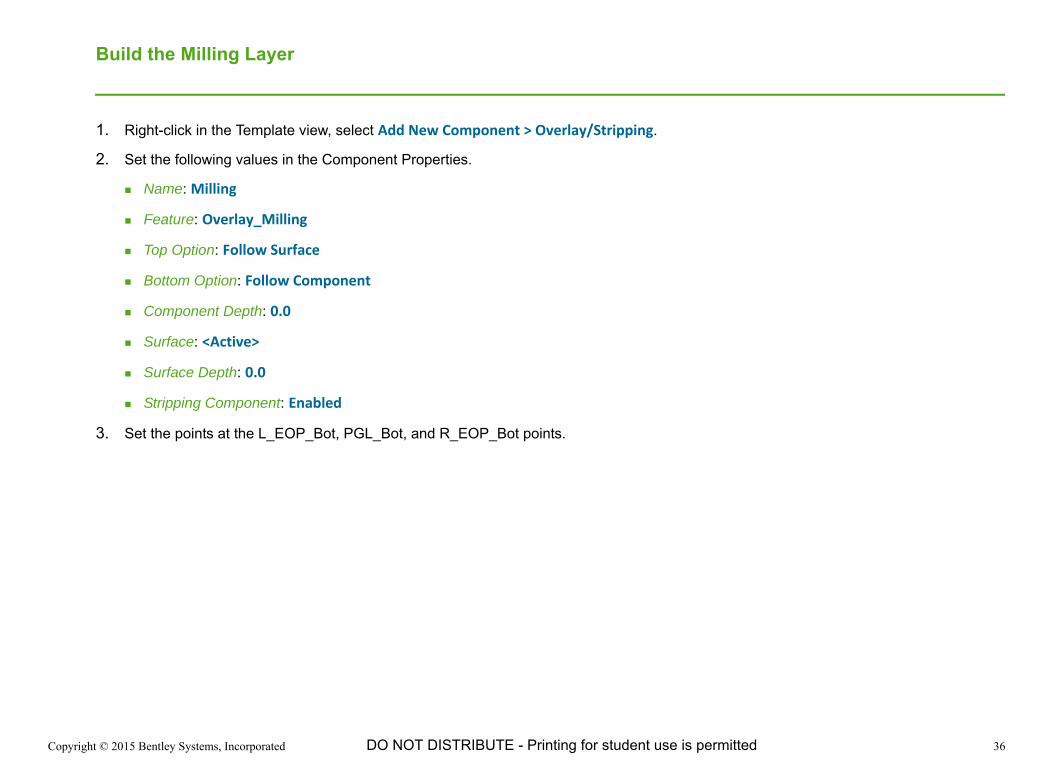
Name: Milling
Feature: Overlay_Milling
Top Option: Follow Surface
Bottom Option: Follow Component
Component Depth: 0.0
Surface: <Active>
Surface Depth: 0.0
Stripping Component: Enabled
3. Set the points at the L_EOP_Bot, PGL_Bot, and R_EOP_Bot points.
Copyright © 2015 Bentley Systems, Incorporated 37DO NOT DISTRIBUTE - Printing for student use is permitted
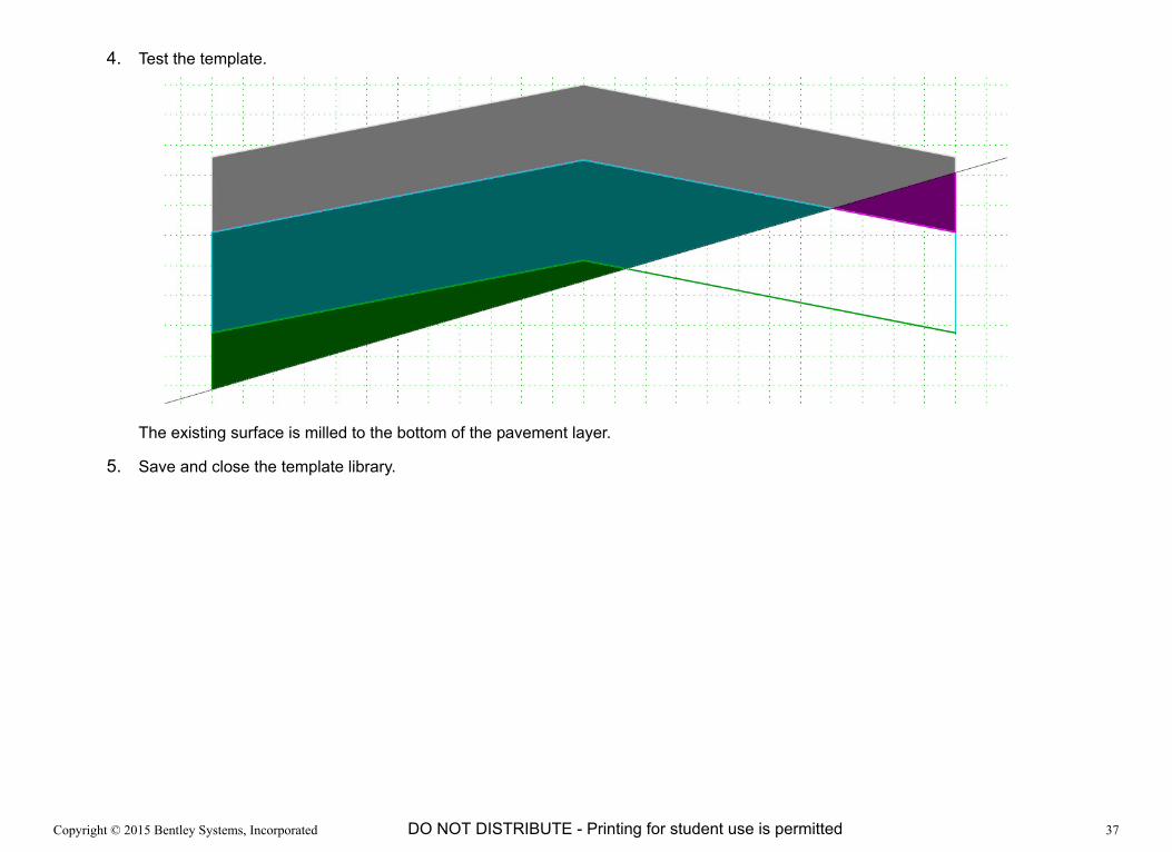
4. Test the template.
The existing surface is milled to the bottom of the pavement layer.
5. Save and close the template library.

Copyright © 2015 Bentley Systems, Incorporated 38DO NOT DISTRIBUTE - Printing for student use is permitted
Review the Results in the Corridor
We will edit the corridor to utilize the new multi-layer template and review the results.
1. Change the template assigned to the corridor to Multi‐Layer Overlay.
2. Change the active profile of the corridor to P_OVERLAY_Under.
3. Review the updated corridor and its cross sections.
All of the components are being utilized and that the results vary along the corridor. Also note that the results will change based on the active profile. Inspect near station 51+00 [1+555] where all components are used on a single cross section.

Copyright © 2015 Bentley Systems, Incorporated 39DO NOT DISTRIBUTE - Printing for student use is permitted
Exercise 5: Creating a Widening Template
Additional components can be added to make more complex templates. For example, a project may require widening in addition to rebuilding the existing pavement with overlay and stripping.
1. Open the Overlay Template Library.
2. Copy the Multi-Layer Overlay template to a new template named Multi‐Layer Overlay and Widening.
3. Double-click the Multi‐Layer Overlay and Widening template to make it active.
4. Define the first layer of the widening.
This first layer of asphalt is the same thickness as the pavement layer in the reconstructed section of road. From a construction perspective it will be paved full width all at once.
a. Right-click in the Template view, select Add New Component > Simple.
b. Set the following values in the Component Properties
Name: Widening Pavement
Feature: Road_Pave_Asphalt
Slope: ‐2.00%
Thickness: .25 [75 mm]
Width: 12 [3.65]
c. Right click in the create template view and select Mirror if the component is not already being mirrored.
d. Place the new pavement at the EOP of the existing template.

Copyright © 2015 Bentley Systems, Incorporated 40DO NOT DISTRIBUTE - Printing for student use is permitted
5. Define the second layer of the widening.
This second layer of pavement is for strength. It will be constructed along with the overlays to create a uniform base for the top layer of pavement.
a. Right-click in the Template view, select Add New Component > Simple.
b. Set the following values in the Component Properties
Name: Widening Pavement Structural
Feature: Road_Pave_Asphalt
Slope: ‐2.00%
Thickness: .50 [150 mm]
Width: 12 [3.65]
c. Right click in the create template view and select Mirror if the component is not already being mirrored.
d. Place the new pavement at the EOP of the existing template and below the top widening pavement layer.

Copyright © 2015 Bentley Systems, Incorporated 41DO NOT DISTRIBUTE - Printing for student use is permitted
6. Define the third layer of the widening.
This third layer is the base below the pavement.
a. Right-click in the Template view, select Add New Component > Simple.
b. Set the following values in the Component Properties
Name: Widening Base
Feature: Road_Pave_Aggregate
Slope: ‐2.00%
Thickness: .50 [150 mm]
Width: 12 [3.65]
c. Right click in the create template view and select Mirror if the component is not already being mirrored.
d. Place the base below the widening pavement layers.
7. Save and close the template library.

Copyright © 2015 Bentley Systems, Incorporated 42DO NOT DISTRIBUTE - Printing for student use is permitted
Review the Results in the Corridor
We will edit the corridor to utilize the new multi-layer overlay and widening template and review the results.
1. Change the template assigned to the corridor to Multi‐Layer Overlay and Widening.
2. Review the updated corridor and its cross sections.
The interior of the roadway is being reconstructed with multiple overlay layers to build up low spots and stripping to remove high spots in the existing surface. Widening on both sides of the roadway is all new construction. There is no overlay or stripping in the widening areas. The existing ground (dirt) that needs to be cut or filled to construct the widening components is part of the standard earthwork and not affected by overlay or stripping components. The overlay and stripping components calculate removal and replacement of asphalt materials, not dirt.
To make this a complete design end conditions should be added to the template so that the earthwork (dirt) volumes can be computed.

Copyright © 2015 Bentley Systems, Incorporated 43DO NOT DISTRIBUTE - Printing for student use is permitted
Exercise 6: Vertical Adjustments - Milling
DescriptionEarlier we learned how different profiles can affect the milling and stripping volumes and thus the construction cost. In this exercise we will lean to use the Vertical Adjustments tool to assist in creating new vertical alignments to perform milling that will result in a full width uniform surface. The first alignment will allow any depth of milling to achieve a full width milling. Next you will create additional milling options that limit the amount of milling but that may result in a more economical or a better engineered solution.
Skills Taught Vertical Adjustments tool using the Minimum Milling mode
Limit the depth of milling with the Use Maximum Milling option

Copyright © 2015 Bentley Systems, Incorporated 44DO NOT DISTRIBUTE - Printing for student use is permitted
Vertical Adjustments
This Vertical Adjustments tool evaluates the existing surface and calculates the elevation of the PGL necessary to minimize overlay above or minimize milling below the surface. The tool can be used in either a Minimum Overlay or a Minimum Milling mode.
The elevation differences between the template and the existing surface can be evaluated at all cross section points or only at the template points. The Examine All Cross Section Points method is useful when you need potholes or other existing surface irregularities to be taken into consideration.
Important: The geometry and the corridor must be in the same DGN when using this tool because it creates a vertical alignment and the corridor must reprocess to determine criteria for the vertical alignment.
Design Stage is also important when running this tool because it processes data at each cross section. The Template Drop Interval Multiplier could cause unexpected results if set to a value other than 1. It is recommended the corridor use a Design State such as Final that has a multiplier of 1 when calculating vertical adjustments.
Minimum Milling OptionUsing the Minimum Milling mode the elevation of the PGL is calculated by adjusting the TOP of the template until it is completely below, and just touching, the existing surface.
The elevation of the PGL is adjusted upward by the Backbone Thickness which compensates for the thickness of the template and effectively calculates the zero milling elevation on the bottom of the template.

Copyright © 2015 Bentley Systems, Incorporated 45DO NOT DISTRIBUTE - Printing for student use is permitted
Minimum Overlay OptionUsing the Minimum Overlay mode the elevation of the PGL is calculated by adjusting the TOP of the template until it is completely above, and just touches the existing surface.
The elevation of the PGL is adjusted upward by the Backbone Thickness which compensates for the thickness of the template and effectively calculates the zero overlay elevation on the bottom of the template. The result is an overlay of exactly zero at the critical point.
When it is necessary to ensure a minimum depth of overlay material the Minimum Overlay Thickness value is set. The PGL is adjusted upward by the Minimum Overlay Thickness. In the following illustration the minimum overlay thickness is identified by the two red arrows. Notice how the template has been shifted upward ensuring a minimum overlay.
Copyright © 2015 Bentley Systems, Incorporated 46DO NOT DISTRIBUTE - Printing for student use is permitted
Create Vertical Alignment for Minimum Milling
In this exercise you will define a new vertical alignment adjusted so the full pavement layer will be constructed without a need for overlay material.
1. Open the Vertical Adjustment ‐ Milling.dgn file.
In the Cross Section view the light gray shape represents the pavement layer and the purple shape represents the milling.
The current model is based on the corridors vertical alignment being at the existing ground elevation.
2. If prompted that Obsolete Civil Data is Found, click Yes to upgrade the data in the file.
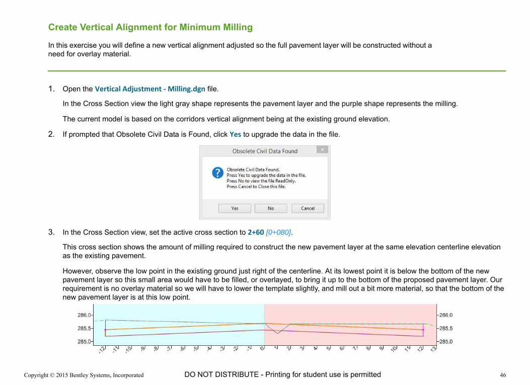
3. In the Cross Section view, set the active cross section to 2+60 [0+080].
This cross section shows the amount of milling required to construct the new pavement layer at the same elevation centerline elevation as the existing pavement.
However, observe the low point in the existing ground just right of the centerline. At its lowest point it is below the bottom of the new pavement layer so this small area would have to be filled, or overlayed, to bring it up to the bottom of the proposed pavement layer. Our requirement is no overlay material so we will have to lower the template slightly, and mill out a bit more material, so that the bottom of the new pavement layer is at this low point.

Copyright © 2015 Bentley Systems, Incorporated 47DO NOT DISTRIBUTE - Printing for student use is permitted
4. Calculate a vertical alignment so that the full pavement thickness will be constructed with no overlay material and the minimum amount of milling possible.
a. Select the Element Selection tool.
b. Hover over the Highway corridor and select the Vertical Adjustments tool from the context sensitive tool bar.
c. Following the on screen prompts, set the following values.
Vertical Name: Milling ‐ Full Depth
Start Station: 0+00
Stop Station: 84+53.46 [2+577.27]
Backbone Thickness: 0.25 [75 mm]
This is the thickness from the profile grade line to the bottom of the template. Assuming the profile grade line is at the finished grade this is the thickness of the pavement layers.
Backbone Parametric Label: {Blank}
Minimum Mode: Minimum Milling
Use Maximum Milling: Disabled
Left Template Range Point: L_EOP
Right Template Range Point: R_EOP
Existing Ground Range: Match Template Range
Solution Option: Examine All Cross Section Points
Maximum Vertical Difference: 0.00
It may take a few minutes to calculate the new vertical alignment. Watch the progress bar in the lower right corner of the screen. Once complete, a new vertical alignment is created and displayed in the profile view.
Copyright © 2015 Bentley Systems, Incorporated 48DO NOT DISTRIBUTE - Printing for student use is permitted
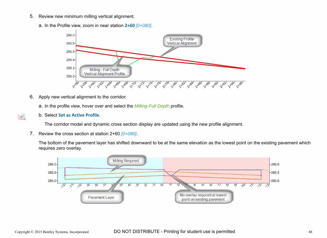
5. Review new minimum milling vertical alignment.
a. In the Profile view, zoom in near station 2+60 [0+080].
6. Apply new vertical alignment to the corridor.
a. In the profile view, hover over and select the Milling-Full Depth profile.
b. Select Set as Active Profile.
The corridor model and dynamic cross section display are updated using the new profile alignment.
7. Review the cross section at station 2+60 [0+080].
The bottom of the pavement layer has shifted downward to be at the same elevation as the lowest point on the existing pavement which requires zero overlay.
Copyright © 2015 Bentley Systems, Incorporated 49DO NOT DISTRIBUTE - Printing for student use is permitted
Limit Milling Depth to a Maximum Depth
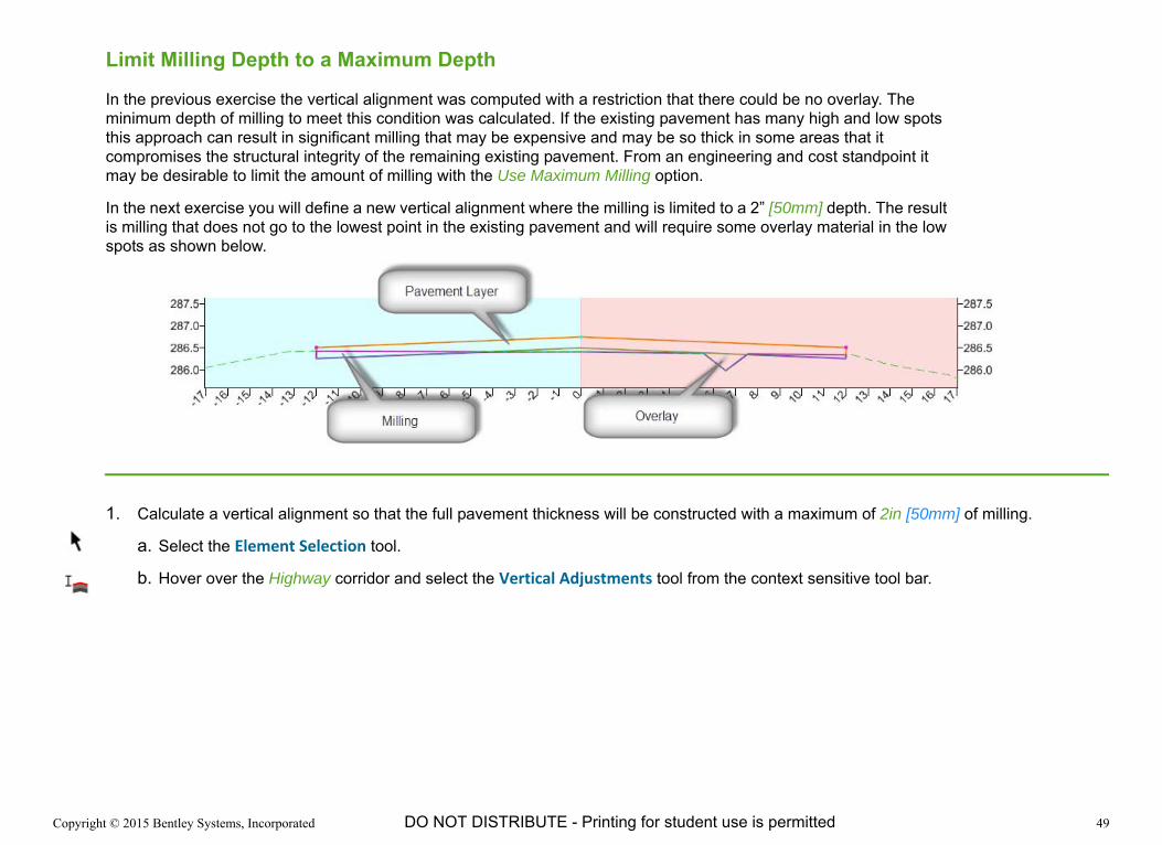
In the previous exercise the vertical alignment was computed with a restriction that there could be no overlay. The minimum depth of milling to meet this condition was calculated. If the existing pavement has many high and low spots this approach can result in significant milling that may be expensive and may be so thick in some areas that it compromises the structural integrity of the remaining existing pavement. From an engineering and cost standpoint it may be desirable to limit the amount of milling with the Use Maximum Milling option.
In the next exercise you will define a new vertical alignment where the milling is limited to a 2” [50mm] depth. The result is milling that does not go to the lowest point in the existing pavement and will require some overlay material in the low spots as shown below.
1. Calculate a vertical alignment so that the full pavement thickness will be constructed with a maximum of 2in [50mm] of milling.
a. Select the Element Selection tool.
b. Hover over the Highway corridor and select the Vertical Adjustments tool from the context sensitive tool bar.

Copyright © 2015 Bentley Systems, Incorporated 50DO NOT DISTRIBUTE - Printing for student use is permitted
c. Following the on screen prompts, set the following values.
Vertical Name: Milling‐Limited Depth
Start Station: 0+00
Stop Station: 84+53.46 [2+577.27]
Backbone Thickness: 0.25 [0.075]
This is the thickness from the profile grade line to the bottom of the template. Assuming the profile grade line is at the finished grade this is the thickness of the pavement layers.
Backbone Parametric Label: {Blank}
Minimum Mode: Minimum Milling
Use Maximum Milling: Enabled
Note: The Use Maximum Milling setting being enabled is the difference from the previous exercise. It limits the amount of milling.
Maximum Milling Thickness: 0.167 [0.050]
This defines the maximum thickness of the milling.
Milling Parametric Label: {Blank}
Left Template Range Point: L_EOP
Right Template Range Point: R_EOP
Existing Ground Range: Match Template Range
Solution Option: Examine All Cross Section Points
Maximum Vertical Difference: 0.00

Copyright © 2015 Bentley Systems, Incorporated 51DO NOT DISTRIBUTE - Printing for student use is permitted
2. Review new minimum milling vertical alignment.
a. In the Profile view, zoom in near station 2+60 [0+080].
3. Apply new vertical alignment to the corridor.
a. In the profile view, hover over and select the Milling-Limited Depth profile.
b. Select Set as Active Profile.
The corridor model and dynamic cross section display are updated using the new profile alignment.
4. Review the cross section at station 2+60 [0+080].
The pavement layer has shifted so that a maximum of 2in [50mm] of milling is required. The maximum milling on this cross section occurs at the left edge of the pavement. Notice that a significant amount of overlay is required with this solution.

Copyright © 2015 Bentley Systems, Incorporated 52DO NOT DISTRIBUTE - Printing for student use is permitted
Exercise 7: Vertical Adjustments - Overlay
DescriptionIn this exercise we will create several vertical alignments that result in different depths of overlay and milling.
Skills Taught Vertical Adjustments tool using the Minimum Overlay mode
Vertical Adjustments tool using the Minimum Overlay Thickness option
Vertical Adjustments tool using the Minimum Milling Thickness option

Copyright © 2015 Bentley Systems, Incorporated 53DO NOT DISTRIBUTE - Printing for student use is permitted
Create Vertical Alignment for Minimum Overlay
In this exercise you will define a new vertical alignment adjusted so the bottom of the pavement layer is position for the minimum depth of overlay required to achieve a uniform full width existing pavement surface.
1. Open the Vertical Adjustment ‐ Overlay.dgn file.
In the Cross Section view the light gray shape represents the pavement layer and the purple shape represents the milling.
The current model is based on the corridors vertical alignment being at the existing ground elevation.
2. If prompted that Obsolete Civil Data is Found, click Yes to upgrade the data in the file.
3. In the Cross Section view, set the active cross section to 2+60 [0+080]. Observe the dip in the existing ground just right of the centerline and notice that at its lowest point it is below the bottom of the pavement layer.

Copyright © 2015 Bentley Systems, Incorporated 54DO NOT DISTRIBUTE - Printing for student use is permitted
4. Calculate minimum overlay vertical alignment.
a. Select the Element Selection tool.
b. Hover over the Highway corridor and select the Vertical Adjustments tool.
c. Following the on screen prompts, set the following values.
Vertical Name: Overlay ‐ Minimum Depth Zero
Start Station: 0+00
Stop Station: 84+53.46 [2+577.27]
Backbone Thickness: 0.25 [75 mm]
This is the thickness from the profile grade line to the bottom of the template. Assuming the profile grade line is at the finished grade this is effectively the thickness of the pavement layers.
Backbone Parametric Label: {Blank}
Minimum Mode: Minimum Overlay
Minimum Overlay Thickness: 0.00
This is the minimum distance from the bottom of the pavement layer to the existing ground.
Overlay Parametric Label: {Blank}
Use Maximum Milling: Disabled
Left Template Range Point: L_EOP
Right Template Range Point: R_EOP
Existing Ground Range: Match Template Range
Solution Option: Examine All Cross Section Points
Maximum Vertical Difference: 0.00

Copyright © 2015 Bentley Systems, Incorporated 55DO NOT DISTRIBUTE - Printing for student use is permitted
5. Review new minimum overlay vertical alignment.
a. In the Profile view, zoom in near station 2+60 [0+080].
6. Apply new vertical alignment to the corridor.
a. In the profile view, hover over and select the Overlay - Minimum Depth Zero profile.
b. Select Set as Active Profile.
The corridor model and dynamic cross section display are updated using the new profile alignment.

Copyright © 2015 Bentley Systems, Incorporated 56DO NOT DISTRIBUTE - Printing for student use is permitted
7. Review the cross section at station 2+60 [0+080]. The bottom of the pavement layer has shifted upward so the minimum overlay between the existing ground and the bottom of the pavement layer is zero.
If you are constructing this overlay in a single lift a zero overlay may be appropriate because it still ensures a minimum pavement thickness. However, if your construction process will be to first pave the overlay to produce a uniform pavement before placing the 0.25 ft [75 mm] final pavement layer you may need a minimum overlay greater than 0. For our exercise lets assume the minimum overlay that can be constructed is 2” [50 mm].
Copyright © 2015 Bentley Systems, Incorporated 57DO NOT DISTRIBUTE - Printing for student use is permitted
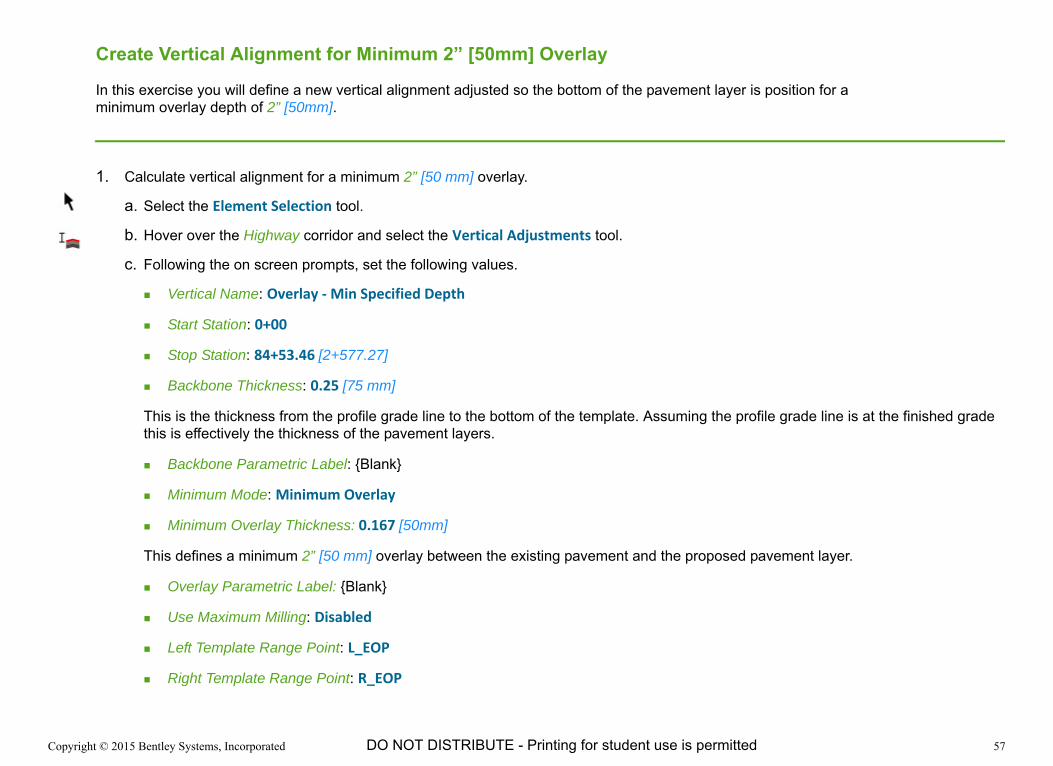
Create Vertical Alignment for Minimum 2” [50mm] Overlay
In this exercise you will define a new vertical alignment adjusted so the bottom of the pavement layer is position for a minimum overlay depth of 2” [50mm].
1. Calculate vertical alignment for a minimum 2” [50 mm] overlay.
a. Select the Element Selection tool.
b. Hover over the Highway corridor and select the Vertical Adjustments tool.
c. Following the on screen prompts, set the following values.
Vertical Name: Overlay ‐ Min Specified Depth
Start Station: 0+00
Stop Station: 84+53.46 [2+577.27]
Backbone Thickness: 0.25 [75 mm]
This is the thickness from the profile grade line to the bottom of the template. Assuming the profile grade line is at the finished grade this is effectively the thickness of the pavement layers.
Backbone Parametric Label: {Blank}
Minimum Mode: Minimum Overlay
Minimum Overlay Thickness: 0.167 [50mm]
This defines a minimum 2” [50 mm] overlay between the existing pavement and the proposed pavement layer.
Overlay Parametric Label: {Blank}
Use Maximum Milling: Disabled
Left Template Range Point: L_EOP
Right Template Range Point: R_EOP

Copyright © 2015 Bentley Systems, Incorporated 58DO NOT DISTRIBUTE - Printing for student use is permitted
Existing Ground Range: Match Template Range
Solution Option: Examine All Cross Section Points
Maximum Vertical Difference: 0.00
2. Review new minimum overlay vertical alignment.
a. In the Profile view, zoom in near station 2+60 [0+080].
3. Apply new vertical alignment to the corridor.
a. In the profile view, hover over and select the Overlay - Min Specified Depth profile.
b. Select Set as Active Profile.
The corridor model and dynamic cross section display are updated using the new profile alignment.

Copyright © 2015 Bentley Systems, Incorporated 59DO NOT DISTRIBUTE - Printing for student use is permitted
4. Review the cross section at station 2+60 [0+080]. The bottom of the pavement layer has shifted upward so the minimum overlay between the existing ground and the bottom of the pavement layer is 2” [50mm].
Copyright © 2015 Bentley Systems, Incorporated 60DO NOT DISTRIBUTE - Printing for student use is permitted
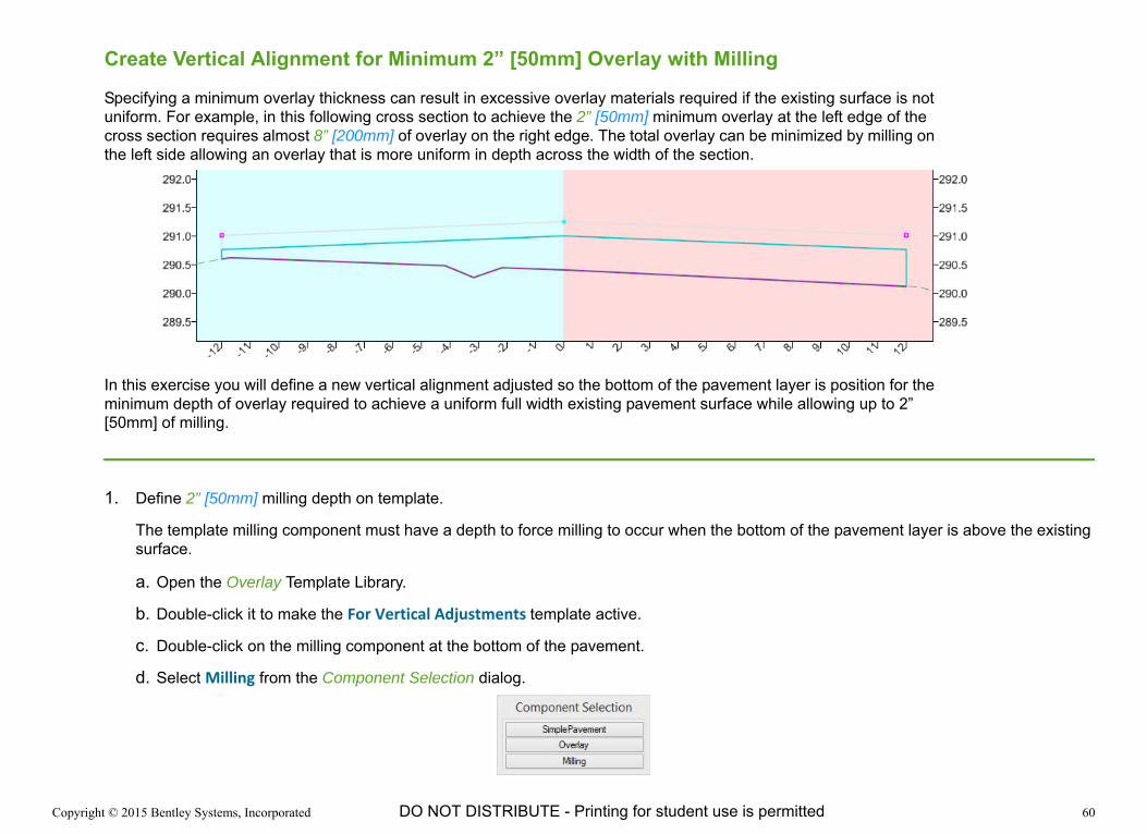
Create Vertical Alignment for Minimum 2” [50mm] Overlay with Milling
Specifying a minimum overlay thickness can result in excessive overlay materials required if the existing surface is not uniform. For example, in this following cross section to achieve the 2” [50mm] minimum overlay at the left edge of the cross section requires almost 8” [200mm] of overlay on the right edge. The total overlay can be minimized by milling on the left side allowing an overlay that is more uniform in depth across the width of the section.
In this exercise you will define a new vertical alignment adjusted so the bottom of the pavement layer is position for the minimum depth of overlay required to achieve a uniform full width existing pavement surface while allowing up to 2” [50mm] of milling.
1. Define 2” [50mm] milling depth on template.
The template milling component must have a depth to force milling to occur when the bottom of the pavement layer is above the existing surface.
a. Open the Overlay Template Library.
b. Double-click it to make the For Vertical Adjustments template active.
c. Double-click on the milling component at the bottom of the pavement.
d. Select Milling from the Component Selection dialog.

Copyright © 2015 Bentley Systems, Incorporated 61DO NOT DISTRIBUTE - Printing for student use is permitted
e. Set the Component Depth to 0.167 [50 mm].
f. Click Apply and close the Component Properties.
g. Save the template and close the Create Template window.
2. Synchronize corridor and template library.
a. Select the Element Selection tool.
b. Select the Template Drop Handle for the corridor. The Template Drop Handle is on the left (looking up station) at the beginning of the corridor.
c. Select the Synchronize with Library button from the context menu.
3. Calculate vertical alignment for a minimum 3” [75mm] overlay and a maximum of 2” [50 mm] of milling.
a. Select the Element Selection tool.
b. Hover over the Highway corridor and select the Vertical Adjustments tool.
c. Following the on screen prompts, set the following values.
Vertical Name: Minimum Overlay with Milling
Start Station: 0+00
Stop Station: 84+53.46 [2+577.27]
Backbone Thickness: 0.25 [75 mm]
Backbone Parametric Label: {Blank}
Minimum Mode: Minimum Overlay
Minimum Overlay Thickness: 0.25 [75 mm]
Overlay Parametric Label: {Blank}
Use Maximum Milling: Enabled
Maximum Milling Thickness: 0.167 [50mm]
Left Template Range Point: L_EOP

Copyright © 2015 Bentley Systems, Incorporated 62DO NOT DISTRIBUTE - Printing for student use is permitted
Right Template Range Point: R_EOP
Existing Ground Range: Match Template Range
Solution Option: Examine All Cross Section Points
Maximum Vertical Difference: 0.00
4. Apply new vertical alignment to the corridor.
a. In the profile view, hover over and select the Minimum Overlay with Milling profile.
b. Select Set as Active Profile.
The corridor model and dynamic cross section display are updated using the new profile alignment.
5. Review the cross section at station 6+60 [0+200]. The bottom of the pavement layer has shifted upward so the minimum overlay between the existing ground and the bottom of the pavement layer is 2” [50mm].