prawn: an interactive tool for software...
TRANSCRIPT

Prawn: An Interactive Tool for Software Visualization
Andrew Chan, Reid Holmes
Department of Computer ScienceUniversity of British Columbia
201-2366 Main MallVancouver BC Canada V6T 1Z4{chana, rtholmes}@cs.ubc.ca
ABSTRACTSoftware systems, by their very nature, are complex ab-stractions of the physical world. Due to this complexity,it is often extremely difficult for developers to fully compre-hend the system they are working on, particularly when theywere not involved in designing it. However, this comprehen-sion is critical; over a system’s lifespan, more time is spentmaintaining it than in any other phase. We introduce thePrawn tool, which uses a variety of information visualizationtechniques to allow developers to see how their code inter-acts with the rest of the system. We believe Prawn reducesthe time and effort required to make a change to a system,and increases developer’s confidence in their changes.
1. INTRODUCTIONBox and arrow diagrams are a key tool in any software de-signer’s toolkit. Nearly any system documentation will con-tain class diagrams of the system or parts of the system,whether in UML1 or in another notation. These diagramsare much easier to understand than a textual description ofthe classes, and they can convey a lot of information in astandardized way.
When a developer joins a software project, the project isoften relatively mature, and the developer’s role is to helpmaintain or extend the code base to meet the customer’sneeds. As a result, the developer must learn about the sys-tem quickly, often on the fly, such as when he or she is askedto make a change. The primary source of support for thedeveloper may not be the system designers or developerswith expert knowledge of the system, but design diagramsand other documentation. The architects of the system mayhave left the company, and with the size and complexity ofsoftware systems, it is unlikely that any one person wouldunderstand every facet of the system.
Unfortunately, design documentation has its shortcomings.It may be incomplete because it was not maintained afterthe initial release of the system. The documentation maycontain incorrect details, or the implementation may vio-late aspects of the design, either through error or due to is-sues that arose during implementation, such as performanceproblems. Even if the documentation is correct and up-to-
1http://www.omg.org/uml/
date, it is likely to be quite voluminous for any non-trivialsystem.
To make a change, developers typically need detailed infor-mation about specific parts of the system, and a high-levelunderstanding of how these parts interact with one anotherand the rest of the system. Although design documentation,even with its shortcomings, would be valuable, a useful toolfor the developer would be an interactive application thatpresents the design of the system, based on the actual imple-mentation. The interactive nature of the application wouldallow each developer to focus on the areas of interest tothem.
An interactive system would also be useful for developerswho are considered experts in the system. With the size ofmodern software systems, diagrams help expert developersreason about the system, and can assist them in explainingthe implementation to new developers. Using an interactivesystem, the expert developer again would not have to at-tempt to find the correct design diagram, but instead couldmanipulate the view to suit his or her needs. An expert de-veloper could also use this system to evaluate whether theimplementation of a system conforms to its design, and todetermine the feasibility of making changes to the system.
Software visualization is an active area of research. Thereare two broad categories of visualization: dynamic and static.Dynamic visualization allows a developer to see the behaviorof a system over time, given a certain set of inputs. It mayor may not reveal details about the system structure, but isuseful for tasks such as performance tuning, or debugging.
Static visualization presents the structure of the system basedon an analysis of its source code. The main problem hasbeen enabling an approach to scale to large systems. Twostatic visualization tools are the Rigi tool [7] and the Sim-ple Hierarchical Multi-Perspective (SHriMP) tool [13]. Rigiprovides a semi-automated process to reverse engineer a sys-tem’s design from its source code. SHriMP builds on this,providing an alternate means of visualizing large data sets(such as software structure) using a zoomable user-interfaceand multiple views.
We were motivated to examine this area for several reasons.One of the authors hoped to use a software visualizationtool to see whether the implementation of a software system

conformed to its design. We were not satisfied with the oneswe tried; either the tool did not contain the functionality wedesired, or it was too difficult to use. At the same time,we felt that with recent advances in software source analysistools2, and zoomable user interface toolkits34, it would bepossible to concentrate on the visualization aspects of a tool,rather than having to build the infrastructure ourselves.
In this paper, we describe the Prawn tool. It is a staticvisualization tool designed to assist a developer in under-standing the structure of a Java system. Although it wouldbe most useful to a developer who has domain knowledge ofthe system being analyzed, it could also help a developer ex-plore an unfamiliar system. Usability and utility were highpriorities in creating Prawn; we felt that a developer shouldbe able to use the tool with minimal effort and training.
The rest of this paper is as follows: In Section 2, we de-scribe the key features of Prawn. Following this, in Sec-tion 3 we present three sample scenarios that illustrate howPrawn could be used. Section 4 describes the related workin this area, with a particular comparison to the SHriMPtool. Section 5 presents an evaluation of the strengths andweaknesses of Prawn, while Section 6 presents future workwhich would increase the utility of the Prawn system. Thefinal section concludes.
2. PRAWNPrawn allows a developer to view the structure of any Javasystem easily. The developer only needs to specify as acommand-line argument the name of a JAR file contain-ing the classes composing the system. Prawn analyzes thesystem and displays the windows shown in Figure 1.
The view presented to the developer mimics the appearanceof a UML class diagram with a node and arc graph. This wasdone to help reduce the learning curve associated with usingthe tool, and thus increase the chances that actual develop-ers would use it. Nodes represent package, abstract class,class, or interface constructs in the system. Arcs representcalls between constructs, and an estimate of the number ofcalls made between constructs is provided5. Many informa-tion visualization techniques were used to ensure that thevisualization would be as useful as possible.
2.1 ColourA developer can easily distinguish between the different kindsof nodes by their colour: packages are blue, abstract classesare dark red, classes are light red, and interfaces are yellow.To reinforce the notion of packages containing subpackages,package nodes are semi-transparent so that packages thatare several levels deep in the structure of the system arecoloured a darker hue of blue. Colour is also used to distin-guish between different types of arcs.
By default, arcs are shown in a muted blue colour so that
2http://www.alphaworks.ibm.com/tech/jikesbt/3http://www.cs.umd.edu/hcil/jazz/4http://zvtm.sourceforge.net/5Since Prawn uses static analysis of code, it is impossible todetermine the exact number of calls. Method calls may bepolymorphic, or may be made based on information that isprovided at run-time
they do not overwhelm the display. Arcs that pass throughpackages are visible due to the package transparency, butarcs that pass through classes are not. When a developermoves the pointer over a node, all of its arcs are displayedand highlighted, regardless of any other settings that mayhave been set. Incoming calls are shown in purple, outgo-ing calls are shown in blue, and structural calls (calls to asuperclass, or an interface that’s implemented, for example)are shown in green.
Although the way colour is used in Prawn does not takeadvantage of the fact that it can be perceived preattentively,we believe that a developer would primarily be interestedin systematically examining the visualization, rather thanlooking for things to pop-out.
Figure 1: Prawn Canvas and Command Window
2.2 AggregationAny non-trivial Java system is composed of hundreds orthousands of classes organized into a package hierarchy. How-ever, a developer is usually only interested in a subset ofthese classes. Within this subset, it is likely that the devel-oper is especially concerned with a small number of classes;he or she needs to understand the rest at a high level.Prawn supports this by aggregating data along the packagehierarchy, then allowing the developer to arbitrarily viewparts of the system at different levels of detail.
The initial view that Prawn presents is of the top-level pack-ages in the system. We define this as those packages locatedat the point where the package hierarchy in a system first di-verges. For example, if the packages in a system include ca,ca.ubc, ca.ubc.foo, and ca.ubc.bar, the top-level pack-ages would be ca.ubc.foo and ca.ubc.bar. If the systemcontains packages that differ immediately at the root level,these packages (say, ca and org) would be shown.
The developer can then select a package to view in more de-tail. The node representing the package is expanded in sizeand its contents are displayed within it. When nodes areexpanded and nodes within nodes are expanded, this visu-ally reinforces the nesting of classes and packages within the

package hierarchy. This is shown in Figure 3. All visualiza-tion takes place within a single window; a multiple-windowsystem would be difficult technically to keep synchronized,and consume valuable screen real-estate.
Figure 3: Prawn Canvas with Nested jEdit Packages
2.3 Navigation and ZoomingOnce the developer has opened several packages to examinetheir contents, the nodes may not fit within the Prawn win-dow. The developer can do one of three things:
• Pan over the contents
• Move nodes as needed so that the nodes of interest fitwithin a window. Arcs are automatically moved withnodes.
• Zoom in and out of the contents. This permits morecontent to fit within the window; text is scaled so thatit remains readable no matter how far out the devel-oper zooms.
Panning and zooming are two separate operations in Prawn,although they could have been combined, as shown in [6].After experimenting with Jazz, a zoomable user-interfacetoolkit that implements this metaphor, we decided againstusing it, as we felt that developers would be able to graspthe separate concepts, but would struggle with controllingpan and zoom simultaneously.
Besides the zoom described, we also adopted a focus+contextmetaphor based loosely on fish-eye views. Nodes that areexpanded occupy more screen real-estate than those that arenot, although we did not have time to implement an algo-rithm to reclaim space when nodes are collapsed. Ratherthan having a single fish-eye lens that a developer wouldmove over the visualization, we felt that developers wouldwant to view multiple aspects of the system in varying levelsof detail, simultaneously. This could be useful when a devel-oper is trying to see the interaction between two particularclasses that are in different packages, as shown in Figure 5.
2.4 Spatial LayoutThe organization of nodes in the graph greatly affects itsusability. Although a developer could use the functionalityprovided to organize nodes as he or she wished, it is timeconsuming to do so. As a result, in Prawn we used threedifferent approaches to lay out nodes in a manner that wefelt would be useful.
At first, we employed the straightforward strategy of layingout the nodes in a grid. Later, we noted that the number oftimes arcs passed through nodes en route to their destinationnode would be greatly reduced if nodes were laid out in aradial manner. At the same time, we wanted to have closelyrelated nodes placed close to one another: a class shouldbe placed close to its superclass, a class should be placedclose to the interfaces it implements, and subclasses of acommon superclass should be placed together. Moreover,the appearance should be similar to that of a UML diagram.
We decided to use each of these methods where appropri-ate. When laying out top-level package nodes, we employedthe radial method. For inheritance and interface implemen-tation hierarchies, we used the strategy of placing closely-related nodes together; this came to be known as the treelayout. Other nodes were laid out using the grid method.
Figure 4: Occlusion Avoidance Algorithm
When a package is expanded to view its contents, nearbynodes often are occluded by the expanded package. A strat-egy was devised whereby occluded nodes were moved to thesame location relative to the expanded node as before thenode had been expanded. This is diagrammed in Figure 4.At first, two packages, A and B, are shown. Then package Bis expanded; its new size is large enough that it will occludepackage A. The new position of A is calculated by first de-termining the length of the line from the center of B through

Figure 2: Prawn Canvas with Three jEdit Packages Open
the center of A to the edge of A. Originally, package A wasmoved by this amount, but to improve the appearance of thelayout, this was changed to a percentage of the line length.
Another consequence of expanding a package is that theparent node often will not be large enough to contain thenewly expanded package. When this happens, Prawn resizesnodes as necessary, from the parent node up to the top-levelnodes.
2.5 Arc ManagementEven with the varying level of detail and layout techniquesdiscussed, the number of arcs shown in a graph quickly be-comes unmanageable. As in the case of classes, a developeris typically only interested in a small subset of the callsmade.
Prawn provides a number of techniques to help developersfind arcs of interest and hide those that are not. Thesetechniques work at different levels of granularity; some applyto the entire graph, while others only apply to a single node.
If the developer is interested in looking at classes that re-ceive a large number of calls, he or she can identify these byspecifying a value for an Arc Width. If an Arc Width of 50is specified, an arc representing 1 to 49 calls will be a pixelwide, an arc representing 50 to 99 calls will be two pixelswide, and so on. Arcs can be up to four pixels wide. Anotheroption for the developer would be to set an Arc Threshold.This is a value that defines the cutoff point for displayingarcs; if the arc represents fewer calls than the value, than itis only displayed when the developer moves the pointer overthe node. Structural calls are not subject to this threshold.
At a finer-grained level, Prawn allows a developer to displayor hide the arcs from a package, class, or interface to othernodes. One application of this would be to ignore classesthat are used for debugging purposes only. While a devel-oper is pointing at a given node, he or she can choose tokeep incoming, outgoing, or structural calls highlighted af-ter the pointer has been moved off. This would be usefulwhen focusing on a given class. Figure 5 shows a view ofPrawn with some of the arcs hidden.

Figure 5: Prawn Canvas of jEdit with Many Arcs Elided
2.6 ImplementationPrawn was implemented using Java 2 and consists of sev-eral modules. The engine for analyzing Java classes wastaken from the FEAT tool6 written by Martin Robillard,a member of the Software Practices Lab at the Universityof British Columbia7. FEAT in turn uses the open-sourceJikesBT toolkit created by IBM for analyzing Java byte-code. A user interface module queries this engine to createan object representation of the nodes and arcs in the vi-sualization. The actual visualization of the graph uses anopen-source Java 2 zoomable UI toolkit called ZVTM.
Prawn is designed to be as extensible as possible, whilemaintaining the scope of visualizing software systems. Itis designed so that a different Java analysis engine couldbe used instead of FEAT with minimal changes to the userinterface module. As well, improved layout managers canbe added by implementing an interface and indicating whenthe new manager should be used.
6http://www.cs.ubc.ca/∼mrobilla/feat/7http://www.cs.ubc.ca/labs/spl
Approximately 19 000 lines of commented Java code werewritten to create Prawn; approximately 8500 lines were slightlymodified FEAT code. An issue that arose early in develop-ment was that FEAT would only return accurate results ifa particular Java rt.jar was used - specifically, the version1.4.1 01 JAR from one of the author’s personal computer.Using earlier or newer versions of the JAR, or even down-loading and installing a clean copy of the Java 1.4.1 01 JREdid not work. We suspect that the problem lies with theJikesBT toolkit, as it was originally designed to analyzeJava 1.1.8 and Java 1.2.2 classes, but we were unable toverify this.
3. SAMPLE SCENARIOSWhile Prawn is not suitable for all software evolution tasks,we present three scenarios where we feel that it would beuseful.
3.1 Discovering Design ViolationsOne of the authors has worked on a medium-sized systemthat provides tools for Undergraduate Advisors in the De-

partment of Computer Science. The CSSIS system consistsof approximately 34 000 lines of code across 150 classes, andis subdivided into several modules. There are two majormodules, one for advising and one for reporting. The au-thor had designed the modules such that they would rely oncommon shared modules, but should not interact directlywith one another. Prawn was used to test whether the im-plementation reflected this.
At the top-level, Prawn shows a ca.ubc.cs package. Ex-panding this package shows two packages: cssis and sis.Expanding the cssis package shows its 12 children, a mix-ture of packages, classes, and interfaces. Among the pack-ages are the advising and reporting packages, which rep-resent the advising and reporting modules.
Placing the pointer over the advising package, it was clearthat there indeed were calls between the advising pack-age and the reporting package in both directions. Afterexpanding each of these nodes, the number of arcs shownon the screen became prohibitive. We chose to focus oncalls from classes in the advising package to classes in thereporting package, so we hid all calls from packages besidesthese packages, then highlighted the incoming calls to theclasses in the reporting package. This allowed us to easilyidentify the classes that would have to be examined.
This task could be accomplished using the UNIX grep8 toolto search for imported classes from the reporting package.However, it would have been more difficult to accomplish:
• It would be difficult to ensure all calls to the reportingpackage were captured without introducing false pos-itives, such as a comment containing the word “re-porting.” This is particularly true in object-orientedsystems as grep cannot compensate for polymorphism.
• The number of calls made from one class to anotherwould be difficult to ascertain, so it would be difficultto prioritize which classes to focus on first
• It would be difficult to see whether there are any pat-terns in the calls. For example, if calls were beingmade from a class and its subclasses to another class,this might not be apparent.
3.2 Refactoring a ClassPrawn can also be useful when refactoring a class or setof classes. Refactoring may be necessary to introduce ad-ditional functionality, to improve the performance of someaspect of the system, or to change the design so that it ismore extensible.
In the CSSIS system, one of the key modules is a user pack-age that contains the functionality for different kinds of usersof the system. Changing any of the classes in the user pack-age would affect many classes in the rest of the system. Ex-panding the nodes until the children of the cssis packageare shown, this becomes clear; four packages call the user
package, including the reporting package and especially theadvising package.
8http://www.gnu.org/software/grep/grep.html
Given the large number of calls between the advising pack-age and the user package, more investigation would be needed.This would especially be the case since the part of the advis-ing module uses Java Servlet pages, and other part is part ofa Java application. Both parts rely on a layer of the modulethat reads and writes information to a database. Expandingthe advising package, the developer can see that the distri-bution of calls from each of these parts to the user packageis roughly equal. Hence, the developer will need to spendtime with each of the developers responsible for these partsto determine how the effort of the changes that are planned.
With Prawn it is possible to quickly ascertain the difficultyof making a particular change to a system. Estimating thedifficulty of making a change and the time required to do isnot a trivial task. Even with domain knowledge of a system,having an interactive tool like Prawn allows a developer tomake predictions with greater confidence, since their analy-sis is grounded in facts taken from the implementation.
3.3 Comprehension and ExtensionWhile the previous scenarios have relied on expert knowl-edge of a system, Prawn can also be used by developers tolearn about the structure of a system and to gain insightinto how the system could be changed.
JHotDraw is a well-known drawing framework created byEric Gamma as a demonstration of how a well designedsystem can take advantage of design patterns. It consistsof 90+ classes and over 20 000 lines of code. One of theauthors had basic knowledge of JHotDraw, but had neverexamined the source code. Using Prawn, he attempted todetermine what changes would be required to add a Koalafigure to JHotDraw’s palette of figures.
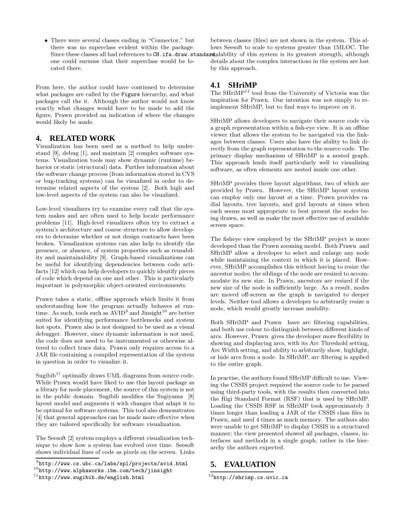
After expanding the CH.ifa.draw node (see Figure 6), theauthor noted the presence of a figures package and ex-panded it (see Figure 7). To reduce the number of callsbeing displayed, he first hid all the calls at the CH.ifa.draw
level, then hid calls within the figures package as well. Hethen proceeded to highlight the structural calls within thefigures package (see Figure 8).
Next, the author noted that KoalaFigure would extend theAttributeFigure class. He then decided to see what classeswithin the figures package called AttributeFigure and itssubclasses. He accomplished this by moving the pointer overeach of these nodes and highlighting all their calls. Afterthis, the author decided to group the non-Figure classesaccording to whether or not they interacted with the Figurehierarchy (see Figure 9). It was useful for the author tozoom out so that more information could be displayed onthe screen.
Based on this information, the author identified several classesthat call each Figure and thus would have to be modifiedfor the addition of the new figure. He also observed that:
• What would seem to be related classes did not callthe Figure classes equally. For example, there wereseveral classes ending in “Handle,” but only some ofthem made calls.
• There were several classes ending in “Connector,” butthere was no superclass evident within the package.Since these classes all had references to CH.ifa.draw.standard,one could surmise that their superclass would be lo-cated there.
From here, the author could have continued to determinewhat packages are called by the Figure hierarchy, and whatpackages call the it. Although the author would not knowexactly what changes would have to be made to add thefigure, Prawn provided an indication of where the changeswould likely be made.
4. RELATED WORKVisualization has been used as a method to help under-stand [9], debug [1], and maintain [2] complex software sys-tems. Visualization tools may show dynamic (runtime) be-havior or static (structural) data. Further information aboutthe software change process (from information stored in CVSor bug-tracking systems) can be visualized in order to de-termine related aspects of the system [2]. Both high andlow-level aspects of the system can also be visualized.
Low-level visualizers try to examine every call that the sys-tem makes and are often used to help locate performanceproblems [11]. High-level visualizers often try to extract asystem’s architecture and coarse structure to allow develop-ers to determine whether or not design contracts have beenbroken. Visualization systems can also help to identify thepresence, or absence, of system properties such as reusabil-ity and maintainability [9]. Graph-based visualizations canbe useful for identifying dependencies between code arti-facts [12] which can help developers to quickly identify piecesof code which depend on one and other. This is particularlyimportant in polymorphic object-oriented environments.
Prawn takes a static, offline approach which limits it fromunderstanding how the program actually behaves at run-time. As such, tools such as AVID9 and Jinsight10 are bettersuited for identifying performance bottlenecks and systemhot spots. Prawn also is not designed to be used as a visualdebugger. However, since dynamic information is not used,the code does not need to be instrumented or otherwise al-tered to collect trace data. Prawn only requires access to aJAR file containing a compiled representation of the systemin question in order to visualize it.
Sugibib11 optimally draws UML diagrams from source code.While Prawn would have liked to use this layout package asa library for node placement, the source of this system is notin the public domain. Sugibib modifies the Sugiyama [8]layout model and augments it with changes that adapt it tobe optimal for software systems. This tool also demonstrates[4] that general approaches can be made more effective whenthey are tailored specifically for software visualization.
The Seesoft [2] system employs a different visualization tech-nique to show how a system has evolved over time. Seesoftshows individual lines of code as pixels on the screen. Links
9http://www.cs.ubc.ca/labs/spl/projects/avid.html10http://www.alphaworks.ibm.com/tech/jinsight11http://www.sugibib.de/english.html
between classes (files) are not shown in the system. This al-lows Seesoft to scale to systems greater than 1MLOC. Thescalability of this system is its greatest strength, althoughdetails about the complex interactions in the system are lostby this approach.
4.1 SHriMPThe SHriMP12 tool from the University of Victoria was theinspiration for Prawn. Our intention was not simply to re-implement SHriMP, but to find ways to improve on it.
SHriMP allows developers to navigate their source code viaa graph representation within a fish-eye view. It is an offlineviewer that allows the system to be navigated via the link-ages between classes. Users also have the ability to link di-rectly from the graph representation to the source code. Theprimary display mechanism of SHriMP is a nested graph.This approach lends itself particularly well to visualizingsoftware, as often elements are nested inside one other.
SHriMP provides three layout algorithms, two of which areprovided by Prawn. However, the SHriMP layout systemcan employ only one layout at a time. Prawn provides ra-dial layouts, tree layouts, and grid layouts at times wheneach seems most appropriate to best present the nodes be-ing drawn, as well as make the most effective use of availablescreen space.
The fisheye view employed by the SHriMP project is moredeveloped than the Prawn zooming model. Both Prawn andSHriMP allow a developer to select and enlarge any nodewhile maintaining the context in which it is placed. How-ever, SHriMP accomplishes this without having to resize theancestor nodes; the siblings of the node are resized to accom-modate its new size. In Prawn, ancestors are resized if thenew size of the node is sufficiently large. As a result, nodesare moved off-screen as the graph is navigated to deeperlevels. Neither tool allows a developer to arbitrarily resize anode, which would greatly increase usability.
Both SHriMP and Prawn have arc filtering capabilities,and both use colour to distinguish between different kinds ofarcs. However, Prawn gives the developer more flexibility inshowing and displaying arcs, with its Arc Threshold setting,Arc Width setting, and ability to arbitrarily show, highlight,or hide arcs from a node. In SHriMP, arc filtering is appliedto the entire graph.
In practise, the authors found SHriMP difficult to use. View-ing the CSSIS project required the source code to be parsedusing third-party tools, with the results then converted intothe Rigi Standard Format (RSF) that is used by SHriMP.Loading the CSSIS RSF in SHriMP took approximately 3times longer than loading a JAR of the CSSIS class files inPrawn, and used 4 times as much memory. The authors alsowere unable to get SHriMP to display CSSIS in a structuredmanner; the view presented showed all packages, classes, in-terfaces and methods in a single graph, rather in the hier-archy the authors expected.
5. EVALUATION12http://shrimp.cs.uvic.ca

The current implementation of Prawn has many strengthsand weaknesses. Several of these weaknesses are not dueto technical limitations, but time limitations that preventedus from implementing them. Work items that are more sub-stantial are discussed in the future work section of the paper.The evaluation section takes the form of a task-based anal-ysis and discussion where Prawn’s suitability for each taskwill be discussed.
We have used our tool throughout its development and dur-ing our scenario generation and we have determined that itsuccessfully scales to visualize systems of jEdit13 size withreasonable response times. jEdit is an open-source text edi-tor written in Java. It is composed of 20 packages containing644 classes, with approximately 23 270 method calls betweenthe classes. It should also be noted that Prawn was also ableto load and visualize the Java Runtime Library, which con-tains 314 packages and 8216 classes, although response timeson an Athlon 750 were on the order of minutes for expandinga node. Nevertheless, we were able to use Prawn to accom-plish a number of tasks which would have been cumbersomewith traditional techniques, and would not have been pos-sible with other similar visualization packages due to thescaling issue.
5.1 Prawn StrengthsWe believe that Prawn has three core strengths: its easeof creating a visualization, its ability to facilitate the ex-ploration of a large system, and its ability to reduce thecomplexity of a visualization of a system.
These strengths are contingent on providing the most rel-evant information possible to the developer in a way thatis easy to understand and manipulate. The focus+contexttechnique used by the tool allows developers to focus on thenodes they are most interested in. The three layout algo-rithms help to optimally place nodes so that determiningwhich nodes to investigate next can be inferred as easily aspossible. The Tree Layout in particular performs a cluster-ing operation by grouping nodes based on the inheritancerelationships between them. These layouts are augmentedby the colour and transparency elements of the nodes whichallow for easy delineation between the different types of ar-tifacts on the screen and the relationships between them.The interaction model allows for simple navigation of thenodes, as well nesting levels within nodes.
5.1.1 Creating an Initial VisualizationThe overhead required to start Prawn and navigate thesource code is minimal. All that needs to be done is fora JAR of the program’s byte code to be provided on thecommand line. Immediately, the Prawn canvas loads alongwith a simple command reference and control panel. Withthis low overhead, systems can be quickly visualized at anystage of development to provide updated information aboutthe system. For example, the authors used Prawn to visual-ize itself during development and typically it took less than30 seconds to create the JAR file, start the visualizationprogram, and start navigating on an Athlon 750.
5.1.2 Large System Exploration13http://www.jedit.org
Exploring large systems requires that developers can havefine-grain control of the amount of information they areseeing, as well as the ability to focus on the aspects ofthe system they are interested in, while ignoring the rest.Prawn facilitates both of these goals through its arc elisionfeatures and its focus+context layout approach.
In the Comprehension and Extension scenario, the authorwas first able to elide all arcs except for the structural arcswithin the figure package to gain insight into the key nodesin the package. While the author examined the figure pack-age in detail, other packages were not shown in detail so thatthey were not a distraction. Later on, the author could haveexpanded packages as necessary to understand how classesin the figure package interacted with them.
Another example of this is the Java Runtime Library. Thislarge collection of classes is certainly cumbersome to exploreby traditional techniques. However, if a developer were totake an interest in only the java.util package they couldfocus only on that package and ignore the majority of theclasses in the runtime. Also, they could focus only on howthe nodes were placed to see how they are related to oneanother. In the case of java.util Prawn clusters the nodesinto 6 primary groups (Collection, SortedSet, Iterator, Map,Map$Entry, and RandomAccess). This clustering can beseen in figure 10. From this grouping, it can be seen thatthe Collection, Iterator, and Map clusters are the largest,and as such could be considered the most important, nodeswith which to begin any code examination task.
Figure 10: Part of the java.util package
While experienced developers usually do not need to ex-plore a system in general, often novice developers requireextra support, especially when learning how to use com-plex frameworks [3] [5]. This is because frameworks oftenlack adequate documentation to help new developers learnhow to use them. However, when users are developing codewithin a framework, their simple systems are suddenly a

small part of a large one which is much harder to under-stand. Using Prawn, these novice developers can see theirsystem in full detail, while showing only major interconnec-tions to the framework, which can allow the developer to seehow their work fits into the overall structure of the system.This can help the developer to understand the implicationsof code they are writing, as well as quickly look at moredetail inside the framework itself if greater detail is needed.
5.1.3 Reducing ComplexityOne of the primary problems with graph representations isthat they quickly become cluttered and do not scale well [9].Prawn separates the task of reducing the complexity of thenodes and the complexity of the arcs into two different prob-lems. The layout algorithms take care of the placement ofnodes. This includes clustering by inheritance hierarchies,and using different layouts based upon the kind of nodes thatare being visualized. However, the authors found that thevolume of arcs were the most problematic for large systems.Therefore, three simple techniques were introduced to makethe graph easier to understand. The arc threshold featureallows arcs of less than a certain weight to be hidden. This isparticularly effective when a developer is trying to identifythe most important classes in the system, without clutter.The arc widths feature can be used when it is importantto preserve all available information while highlighting onlythe most important arcs. The third technique allows devel-opers to hide specific classes of arcs. These classes are: All
Arcs, Incoming Arcs, Outgoing Arcs, and Structural
Arcs. These arc elision features can be chosen for wholepackages or just individual nodes depending on what thecursor is over when the key is selected. Further, the mousecan be hovered over any node in order to see the full infor-mation. This allows a clean high-level view while allowingthe low-level details to be quickly determined.
5.2 Prawn WeaknessesThe primary weaknesses of Prawn are directly related tosome of its primary strengths as well. As the authors de-veloped the tool they implemented the elision and layoutmechanisms that exist in the tool. However, several exten-sions are required to make these metaphors fully functional,and to maximize their effectiveness.
The focus+context model could be dramatically improvedto place the context nodes in a more optimal manner. Thecurrent algorithm pushes them to the periphery and doesnot consider any form of rank on these context nodes. Theclustering model could be aggregated to arcs such that arcsgoing to subclasses could instead go to a superclass or ab-stract class. This could help reduce the arcs going to sub-classes, as well as reinforce the connections between differentclass hierarchies. The visual encoding scheme could be ex-tended to include multiple glyph types which would helpto greater differentiate the different nodes as well as sup-ply extra information about them (perhaps connectedness,etc). Animated transitions could be used to resize the nodeswhen nested structures are opened such that the new nodesall fit on the screen at once. Also, the text labels on thenodes should be staggered in some way so that they do notocclude one another.
5.2.1 Layout
The layout, in particular, is a project unto itself. Simplelayout strategies were identified and implemented in theproject, but a great deal more work could be done in thiscase. Prawn does not adequately layout any nodes that arenot involved in inheritance hierarchies. Therefore, simpleutility classes are often grouped into a box layout at thetop of a package structure. As these classes tend to be usedthroughout the code these box structures are often difficultto comprehend. Some form of weighted clustering / layoutshould be used so classes which are used often are givenextra space so that it can be clear that they are impor-tant. Conversely, nodes which are tightly coupled by lots ofcalls between them could be clustered together to gain moreof a function-based layout. Implementing advanced algo-rithms, such as those used by Sugibib could also increasethe effective use of space by the tool. Also, our algorithmwhich keeps nodes from overlapping one another is a simplematter of collision avoidance, and doesn’t try to optimallyplace these nodes. Prawn also makes no effort to reduceedge crossings which can unnecessarily complicate diagrams.Further arc elision by identifying arcs which are not part ofstructural or calling relationships and hiding them could alsohelp to reduce the number of edges on the graph.
5.2.2 Artifact ManipulationWhen navigating the system, often groups of nodes need tobe examined at once. Currently, nodes can only be selectedindividually or by packages. Allowing custom node groupsto be selected and manipulated as one would certainly al-low for custom layouts to be made more easily. Also, arcsare not updated when nodes are in transition, only whenthey are moved to new locations. This can make placinga node optimally a trial and error operation. However, itis unlikely that all arcs could be dynamically updated asthe node is dragged. A better solution would be to dy-namically update as many arcs as possible, giving highestpriority to structural arcs and those with the most calls orthose that are highlighted. This general approach was usedin the H3 system [10]. Supporting text searches, and classi-fication searches (selecting all interfaces for example) couldalso help to select subsets of nodes for group manipulation.
5.3 Lessons LearnedOver the course of this project, we learned several things:
• Creating an effective layout algorithm for placing nodesin a graph is a very difficult problem.
• Choosing an effective colour scheme is difficult, oncethe needs of people who are colour-blind are consid-ered. Even once the colours have been set, it is easyto overuse colour, resulting in a display that is highlycluttered. This was apparent in drawing arcs; arcswere originally drawn in very dark colours, which madeit very difficult to read the visualization.
• Making the visualization scale beyond trivial examplesrequired us to investigate how we could convey moreinformation using a few properties, and how we couldhide unimportant information.
• No matter how advanced the information visualizationtechniques are, if the tool requires a significant amountof effort to use, it will not be adopted in the real world.

• Zoom is not the perfect solution for everything. Zoom-ing out allows more information to be displayed, butat the cost of increased clutter.
• Tackling a problem that has seen 10 years of researchin the Rigi and SHriMP projects in the space of onemonth was slightly ambitious. But we did better. Sothere14.
6. FUTURE WORKSeveral work items remain which, if implemented, wouldmake Prawn a much more complete and effective tool. Themost important, and fundamental of these is integration intoan IDE. This IDE integration would allow for even less over-head in visualizing systems. The integration would be atwo-way process. Developers browsing the source could pullup a pictorial representation of the part of the system theywere currently looking at, as well as go from the nodes inthe graph drilling down into the source code. Advancedquerying can also help to reduce the amount of navigationthat is required in the system (for instance, find all occur-rences of abstract classes which implement an interface andare extended by these three sample applications).
Further improvements in the visualization could be realizedby only looking at subsets of the graph. Currently nodescan be collapsed but are still present. Visualizing only oneor two levels from any single node could help to make thegraph size smaller and limit the scope of navigation to nodesknown to be somehow related to the concern being cur-rently analyzed. Navigation could be simplified by providingan overview radar view, as well as making the links active(clicking on a directed link will take you to the target of thatlink).
Data flow information can also be integrated into the tool tosee how data is accessed throughout the system. Currentlymethod data is maintained by the tool but is not used foranything except for calculating dependencies between nodes.Further development could allow for drilling into specificmethods in classes to focus only on the dependencies of spe-cific methods, instead of whole classes. This could also beuseful for determining fine-grain calls and called-by relation-ships.
Prawn could also annotate the visualization with additionalinformation from CVS or a bug-tracking database, in addi-tion to providing links into the source code from the visual-ization. Tools such as Hipikat15 exist that actively providethis information to a developer, although they have not beenused in this particular context.
7. CONCLUSIONWe have developed the Prawn program visualization tool.This tool is a static, offline visualization system which istargeted at developers who need to get a better overview ofhow their system’s components interact with one another.By leveraging the graphical node-link metaphor the detailsabout how individual methods interact can be aggregatedto classes, packages, and interfaces to reduce the cognitiveload on the developer. The front-end was designed through
14We are being facetious, of course15http://www.cs.ubc.ca/labs/spl/projects/hipikat.html
an iterative process which took advantage of many informa-tion visualization techniques to reduce this cognitive loadand increase the effectiveness of the tool. Through a simpleset of scenarios we illustrated three simple tasks that Prawncan be used for during the development life-cycle. We be-lieve that with some future work, this tool can be made intoa low-overhead way to help developers quickly understandcomplex software systems.
8. REFERENCES[1] Ronald Baecker, Chris DiGiano, and Aaron Marcus.
Software visualization for debugging. CACM,40(4):44–54, 1997.
[2] Thomas Ball and Stephen G. Eick. Softwarevisualization in the large. IEEE Computer,29(4):33–43, 1996.
[3] G. Butler and P. D’enomm’ee. Documentingframeworks to assist application developers, 1997.
[4] H. Eichelberger and J. Wolff von Gudenberg. On thevisualization of java programs. In LNCS 2269, S.Diehl (ed): Software Visualization InternationalSeminar, pages 295–306. Springer, 2001.
[5] Gerhard Fischer, Scott Henninger, and David F.Redmiles. Cognitive tools for locating andcomprehending software objects for reuse. In ICSE,pages 318–328, 1991.
[6] George W. Furnas and Benjamin B. Bederson.Space-scale diagrams: understanding multiscaleinterfaces. In Proceedings of the SIGCHI conference onHuman factors in computing systems, pages 234–241.ACM Press/Addison-Wesley Publishing Co., 1995.
[7] S. Tilley H. Mueller, M. Orgun and J. Uhl. A reverseengineering approach to subsystem structureidentification. Journal of Software Maintenance:Research and Practice, 5(4):181–204, 1993.
[8] S. Tagawa K. Sugiyama and M. Toda. Methods forvisual understanding of hierarchical systems. In IEEETrans. Syst. Man, volume 11, pages 109–125, 1981.
[9] Michael F. Kleyn and Paul C. Gingrich.Graphtrace–understanding object-oriented systemsusing concurrently animated views. In Conferenceproceedings on Object-oriented programming systems,languages and applications, pages 191–205. ACMPress, 1988.
[10] Tamara Munzner. H3: Laying out large directedgraphs in 3d hyperbolic space”. In Proceedings of the1997 IEEE Symposium on Information Visualization,pages 2–10. IEEE Computer Society Press, 1997.
[11] Wim De Pauw, Richard Helm, Doug Kimelman, andJohn Vlissides. Visualizing the behavior ofobject-oriented systems. In Proceedings of the eighthannual conference on Object-oriented programmingsystems, languages, and applications, pages 326–337.ACM Press, 1993.
[12] Norman Wilde and Ross Huitt. Maintenance supportfor object-oriented programs. IEEE Transactions onSoftware Engineering, 18(12):1038–1044, 1992.

[13] J. Wu and M.-A.D. Storey. A multi-perspectivesoftware visualization environment. In Proc. ofCASCON’2000, pages 41–50, 2000.

Figure 6: Prawn Canvas
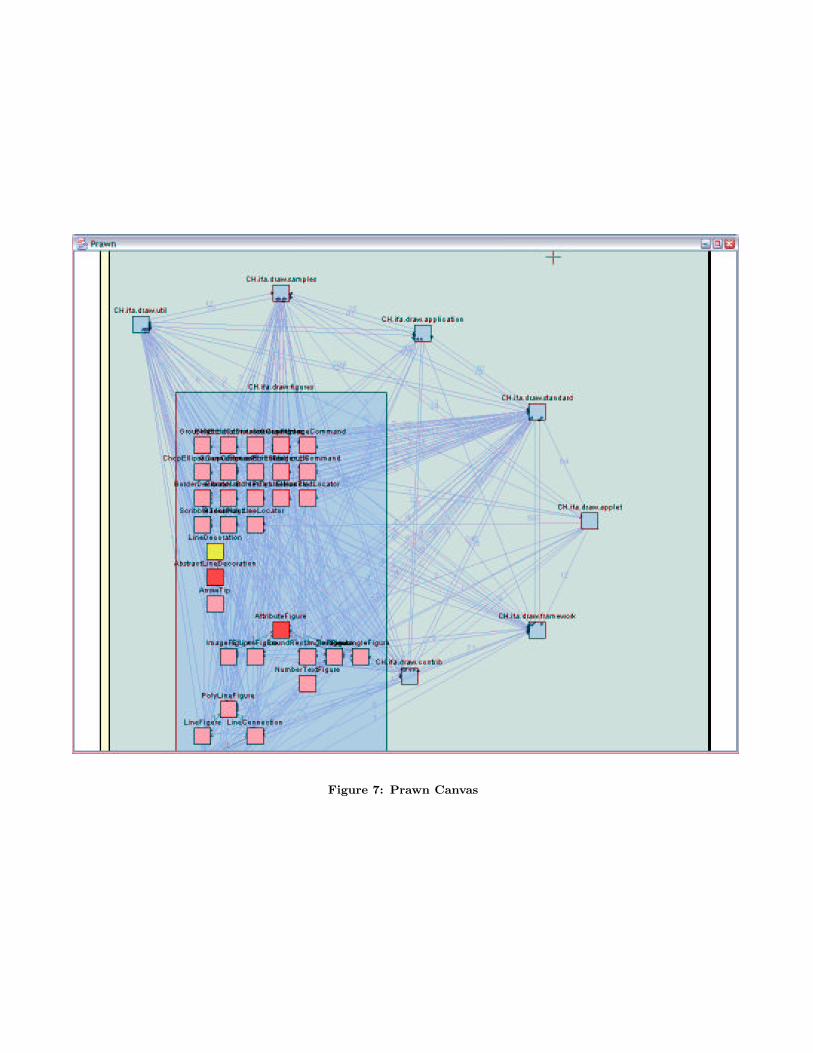
Figure 7: Prawn Canvas
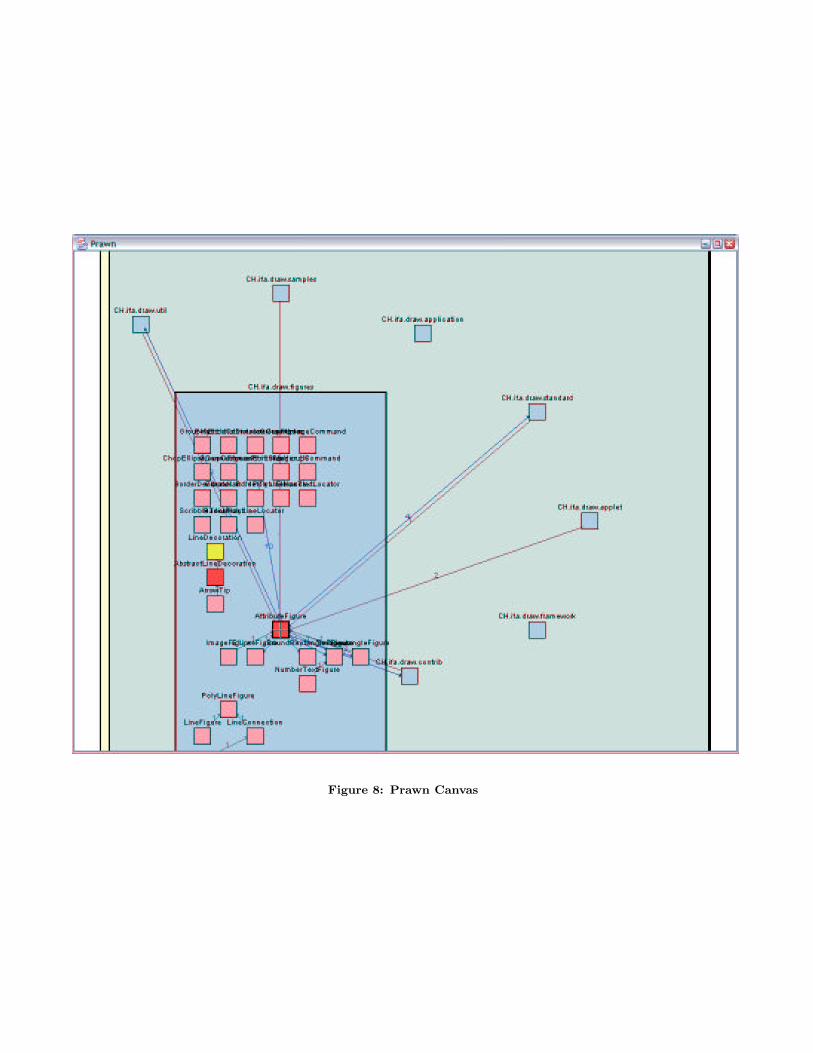
Figure 8: Prawn Canvas

Figure 9: Prawn Canvas