pre-2dsp pl ii(plurison)op-2s · test/m eq band bass 4. eq setup button select up to 5 eq band...
TRANSCRIPT

Pre-2DSP Preamp-processor
Audio Refinement
PrecisionInnovation & Musicality
by
OWNER INFORMATION

2
PRE-2DSP PREAMP-PROCESSOR
ACKNOWLEDGMENT & TRADEMARK

Pre-2DSP PL
PreAmp-Processor
INTRODUCTION ..................................................................................................
DESIGN PHILOSOPHY ........................................................................................
UNPACKING AND INSPECTION ........................................................................
CARE USE ........................................................................................................
FRONT PANEL FUNCTIONS ...............................................................................
REAL PANEL FUNCTIONS .................................................................................
REAL PANEL CONNECTIONS ............................................................................
CONNECTIONS OF PRE-2DSP .............................................................................
REMOTE CONTROL ............................................................................................
SPECIAL RECOMMENDATIONS AND NOTICE ITEMS ....................................
OPERATION .........................................................................................................
LCD DISPLAY AND INDICATORS .............................................................
INPUT SOURCE SELECTION .....................................................................
AUDIO AND VIDEO INPUT EXPLANATIONS ..........................................
RC-5 REMOTE COMMANDS CODE ......................................................
OSD (ON-SCREEN DISPLAY) .....................................................................
MASTER VOLUME CONTROL ...................................................................
BALANCE SETTING ...................................................................................
MUTE MODE ..............................................................................................
TEST A/M MODE ........................................................................................
SOUND FIELD PROCESSING .....................................................................
SPEAKER PLACEMENT .............................................................................
DELAY CALIBRATION ...............................................................................
TIME DELAY ADJUSTMENT ON CENTER CHANNEL SPEAKER ...........
TIME DELAY ADJUSTMENT ON SURROUND SPEAKER ........................
BASS CROSSOVER NETWORK SETTING .................................................
SPEAKER MODE WITH BASS MANAGER ................................................
PROLOGIC II MODE ....................................................................................
SAVING PRESETS ......................................................................................
LOADING PRESETS ....................................................................................
BYPASS SETTING .......................................................................................
TAPE MONITOR ..........................................................................................
EQUALIZATION ..........................................................................................
RESETTING .................................................................................................
DRC (DYNAMIC RANGE COMPRESSION) ...............................................
TROUBLESHOOTING...........................................................................................
SPECIFICATIONS ................................................................................................
RECOMMENDATIONS .........................................................................................
Record the following information for future reference
Serial Number Purchase Date
Dealer Name Dealer Phone Number
:
:
:
:
:
4
4
4
4
5
6
7
8
10
11
11
12
12
12
13
14
15
15
15
16
16
17
17
18
18
19
19
20
22
22
22
23
23
23
23
24
24
25
3
TABLE OF CONTENTS

RC-DSP Remote Controller with AA batteriesDetachable AC CordRemote Connection cord Owner's Information
Carefully unpacking your Pre-2DSP and locate the enclosed accessories:
Please read the operating instructions before connecting the Pre-2dsp to your audio/video system.
Thank you for your purchase of the Audio Refinement Pre-2dsp, pre/processor. It is precisely crafted innovatively designed and extremely reliable. We appreciate your faith in our products and we trust that your Pre-2dsp will reward you with many years of audio/video pleasure.
Audio Refinement was conceived to offer the renowned musicality or "sonic signature" of YBA Electronics by Yves-Bernard ANDRE' in a more affordable range of products. It benefits from the same design philosophy and attention to minute detail that is the hallmark of YBA.
The choice of materials is also an important part of the design of your Audio Refinement Pre-2dsp, the bottom is made of non-magnetic aluminum, the other parts are brushed and colored aluminum.
The transformer is suspended to reduce the transmission of its vibrations to the rest of the circuitry.
The PRE/PROCESSOR has only 3 feet which is the ideal way to drain vibrations.
The mechanism is designed to be as compact and as rigid as possible. The small physical size of your Audio Refinement Pre-2dsp moves the resonant frequencies out of the audio domain.
An important design goal for Audio Refinement is the control of parasitic vibrations. These me-chanical vibrations in the air have a negative effect on the purity of sound. The impact of these vibrations depends on the size of the audio equipment, the internal components and the rigidity of the construction. The solutions chosen for Audio Refinement include:
Do not handle your AC cord with wet hands. If liquid spills on your Pre-2dsp, unplug immediately and contact your dealer for cleaning instructions.
To avoid damage to your Pre-2dsp, we recommend that you disconnect the AC during electri-cal storm or if the unit will be unused for an extended period of time.
Ensure that your main AC voltage matches the voltage marked on the rear of the unit and on the exterior of the shipping carton.
Do not remove the top cover of your Pre-2dsp or attempt to modify any circuitry. This will void your guarantee and could result in serious injury.
Always turn the Pre-2dsp off before making any connections. Ensure that the speaker cables of your power amplifier do not touch each other. A short circuit will damage the unit and is not covered under the guarantee!
Keep your Pre-2dsp out direct sunlight. Because it could interfere with the remote control sensor.
Keep the Pre-2dsp away from heat sourcres such as hot air ducts, radiators and moistures sources such as open windows.
4
INTRODUCTION
DESIGN PHILOSOPHY
UNPACKING AND INSPECTION
CARE & USE

1 2 3 4 5 6 7 8
10 11 13129 1514
FRONT PANEL FUNCTIONSFRONT PANEL FUNCTIONS
1. POWER Button1. POWER Button
This button to turns ON or STANDBY Pre-2DSP.ON STANDBY
Activate the selected EQ band setting
3. REC ON/OFF Button 3. REC ON/OFF Button
5. FIELD Button 5. FIELD Button
6. INPUT/SELECT Button 6. INPUT/SELECT Button
2. EQ ON/OFF Button2. EQ ON/OFF Button
Press this button will be on and press again will be off.
Select among 6 different sound fields
Select different source inputs.Select the length of Delay time for SL/SR/C channels.Select the length of Balance for L/C/R/SL/SR/LFE channels.Select the length of Test/M for L/C/R/SL/SR/LFE channels.Select up to 5 EQ Band +/- adjusts.Select bass crossover (80Hz, 90Hz, 100Hz, 110Hz, 120Hz)
DelayBalanceTest/M
EQ Bandbass
4. EQ SETUP Button 4. EQ SETUP Button Select up to 5 EQ band settings.
12. REMOTE Sensor12. REMOTE SensorThis sensor receives a signal from the remote handset.
8. BALANCE Button 8. BALANCE Button
7. VOL/ADJUST Button 7. VOL/ADJUST Button
First press this button then press vol button to set 5CH output volume.Custom set the volume setting for 6 channels.
9. POWER Indicator 9. POWER Indicator This red color LED lights up when STANDBY.This green color LED lights up when POWER ON.
STANDBY.POWER ON
10. BYPASS Indicator 10. BYPASS Indicator This red color LED lights up when Bypass ON.Bypass ON.
13. LCD Display13. LCD Display
14. EX-SC Indicator14. EX-SC IndicatorU P - G R A G E f o r E X 6 . 1 .
15. Speaker Configuration LEDs15. Speaker Configuration LEDsEach LED represents the status of an individual channel. When a particular channel is active, the LED LIGHTS UP. Red color LED light means this particular channel has been set to output a wider frequency range that contains bass signal between 20Hz to 120Hz.Green color LED light means this particular channel doesn"T contain the bass signal between 20Hz to 120Hz.
11. TAPE Monitor Indicator 11. TAPE Monitor Indicator This green color LED lights up when Tape Monitor ON.
Tape Monitor ON.
Increase/decrease the Volume level.Increase/decrease the Delay times. Increase/decrease the Balance level.Increase/decrease the EQ level.
Volume DelayBalanceEQ
This display provides you with important information regarding system status and settings.It is important to be familiar with all the indications on the display in order to have the system function properly.
5
REAL PANEL FUNCTIONSREAL PANEL FUNCTIONS
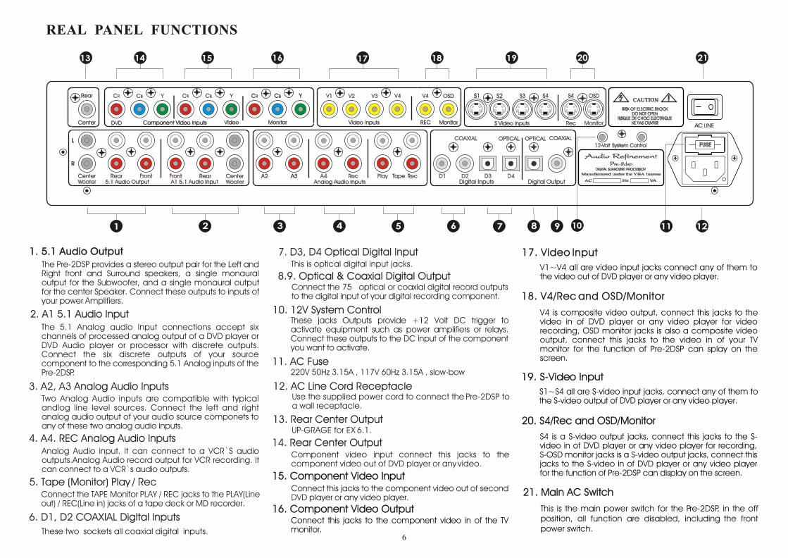
1. 5.1 Audio Output1. 5.1 Audio OutputThe Pre-2DSP provides a stereo output pair for the Left and Right front and Surround speakers, a single monaural output for the Subwoofer, and a single monaural output for the center Speaker. Connect these outputs to inputs of your power Amplifiers.
The 5.1 Analog audio Input connections accept six channels of processed analog output of a DVD player or DVD Audio player or processor with discrete outputs. Connect the six discrete outputs of your source component to the corresponding 5.1 Analog inputs of the Pre-2DSP.
3. A2, A3 Analog Audio Inputs 3. A2, A3 Analog Audio Inputs
5. Tape (Monitor) Play / Rec 5. Tape (Monitor) Play / Rec
2. A1 5.1 Audio Input2. A1 5.1 Audio Input
Two Analog Audio inputs are compatible with typical andlog line level sources. Connect the left and right analog audio output of your audio source componets to any of these two analog audio inputs.
Connect the TAPE Monitor PLAY / REC jacks to the PLAY(Line out) / REC(Line in) jacks of a tape deck or MD recorder.
11. AC Fuse11. AC Fuse
Use the supplied power cord to connect the Pre-2DSP to a wall receptacle.
12. AC Line Cord Receptacle12. AC Line Cord Receptacle
4. A4. REC Analog Audio Inputs 4. A4. REC Analog Audio Inputs Analog Audio input. It can connect to a VCR`S audio
outputs.Analog Audio record output for VCR recording. It can connect to a VCR`s audio outputs.
These jacks Outputs provide +12 Volt DC trigger to activate equipment such as power amplifiers or relays. Connect these outputs to the DC input of the component you want to activate.
10. 12V System Control10. 12V System Control
7. D4 Optical Digital Input D3, 7. D3, D4 Optical Digital InputThis is optical digital input jacks.
Connect the 75 optical or coaxial digital record outputs to the digital input of your digital recording component.
8.9. Optical & Coaxial Digital Output8.9. Optical & Coaxial Digital Output
220V 50Hz 3.15A , 117V 60Hz 3.15A , slow-bow
UP-GRAGE for EX 6.1. 13. Rear Center Output13. Rear Center Output
Component video input connect this jacks to the component video out of DVD player or any video.
14. Rear Center Output14. Rear Center Output
15. Component Video Input15. Component Video InputConnect this jacks to the component video out of second DVD player or any video player.
Connect this jacks to the component video in of the TV monitor.
17. Video Input17. Video Input
16. Component Video Output16. Component Video Output
V1~V4 all are video input jacks connect any of them to the video out of DVD player or any video player.
S1~S4 all are S-video input jacks, connect any of them to the S-video output of DVD player or any video player.
19. S-Video Input19. S-Video Input
18. V4/Rec and OSD/Monitor18. V4/Rec and OSD/Monitor
V4 is composite video output, connect this jacks to the video in of DVD player or any video player for video recording, OSD monitor jacks is also a composite video output, connect this jacks to the video in of your TV monitor for the function of Pre-2DSP can splay on the screen.
S4 is a S-video output jacks, connect this jacks to the S-video in of DVD player or any video player for recording, S-OSD monitor jacks is a S-video output jacks, connect this jacks to the S-video in of DVD player or any video player for the function of Pre-2DSP can display on the screen.
20. S4/Rec and OSD/Monitor20. S4/Rec and OSD/Monitor
21. Main AC Switch21. Main AC Switch
This is the main power switch for the Pre-2DSP, in the off position, all function are disabled, including the front power switch.
6
6. D1, D2 COAXIAL Digltal Inputs 6. D1, D2 COAXIAL Digltal Inputs These two sockets all coaxial digital inputs.

TV MonitorTV Monitor
S-Video InS-Video In
Video InVideo In
CompositeComposite ComponentComponent
Video InVideo In
Play/OutPlay/Out Rec/InRec/In
InIn
OutOut
AudioAudio AudioAudio VideoVideo
OutOut
S-VideoS-Video
InIn
Video Cassette RecorderVideo Cassette Recorder
AudioAudio
OutputOutputOutputOutput
Coaxial DigitalCoaxial Digital
CD Player/TransportCD Player/TransportDVD/Video PlayerDVD/Video Player
Video OutVideo Out
StereoStereoDigital OutDigital Out
ComponentComponent
Video OutVideo Out
Audio OutAudio Out
CompositeComposite
DVD/Audio PlayerDVD/Audio Player
S-Video OutS-Video Out
RR
LL
InputInput
++InputInput
++InputInput
++InputInput
++
InputInput
++
AmplifierAmplifier
CenterCenter
LFE SpeakerLFE Speaker Center SpeakerCenter Speaker Left SurroundLeft Surround Right SurroundRight Surround Right SpeakerRight SpeakerLeft SpeakerLeft Speaker
AmplifierAmplifier AmplifierAmplifier AmplifierAmplifier AmplifierAmplifier
LSLS RSRS LL RR
SubwooferSubwoofer
REAL PANEL CONNECTIONSREAL PANEL CONNECTIONS
7

1. 5.1 Audio Output
a. Center Channel Output
b. Subwoofer Output
Connect the Center channel output of your Pre-2DSP to the input of a mono amplifier or to the channel of the multi-channel amplifier that is connected to your center (C) speaker.
Connect the subwoofer output of your Pre-2DSP to the input of active subwoofer.
c. Left and Right Rear Channel Outputs
Connect the Left and Right rear outputs of your Pre-2DSP to the input of the two channel amplifier or to two channels of a multi-channel amplifier that are connected to your left and right surround (LS, RS) speakers.
d. Front Left and Right Channel Outputs
Connect the Left and Right Front channel outputs of your Pre-2DSP to either the inputs of a two channel amplifier or to two channels of a multi-channel amplifier that are then connected to your main front left and right (L, R) speakers.
2. 5.1 Analog Inputs
The 5.1 Analog Input are designed to accept up to six channels of processed analog output from a DVD player or DVD Audio player other component with discrete outputs. Connect the six discrete outputs of your source component to the corresponding 5.1 Analog Input of the Pre-2DSP.
3. A2 A3 Analog Audio Input Connections
The A2 A3 analog inputs are compatible with typical analog line level sources such as CD players, MiniDisc players, cassette decks, etc. connect the left and right analog audio outputs of your audio/video source components to these inputs.
4. A4 Input and Rec (Record and Playback) Connections
Use the A4 inputs and outputs for the VCR you intend to use to record the picture and sound. The signal present at the V4 Record output sends analog audio from whichever of the other A2 A3V2 V3 Audio/Video or Audio-only inputs you select.
1. Connect the left and right audio output connectors from the VCR you'll use for recording to the A4/V4 Input connectors of the Pre-2DSP.
2. Connect the left and right A4 REC (Record) Output connectors of the Pre-2DSP to the left and right audio input connectors of the VCR.
3. Connect the composite video output connector of your VCR to the V4 or S4 input of the Pre-2DSP and connect the V4 REC or S4 REC Composite Record Output connectors of the Pre-2DSP composite video input connectors of the VCR.
5. Tape monitor play and REC Connections
The audio signal from the source you selected for the main zone is routed to both pairs of Record Output connectors. Connect the lift and right play/output of your tape deck to the left and right of any of the Pre-2DSP's A2 A3 A4 input connectors. Next, connect the left and right audio record/input connectors of your tape deck to either pair of Left and Right channel Record Output connectors of your Pre-2DSP.
6. Digital Audio Input Connections
Your Pre-2DSP has four digital input connections: three Coax RCA jack, one Optical Toslinks.
a. Coaxial Digital Inputs
The four Coax Inputs on the Pre-2DSP accept a standard S/PDIF digital bitstream form any CD player, DVD player, DSS receiver, or other digital component equipped with a 75
8
CONNECTIONS OF PRE-2DSP

the digital bitstream to both the Coax and Optical Toslink output connectors. Connect either the Optical or the 75 Output connectors of the Pre-2DSP to the digital record input of your digital recorder.
8. 12-VOLT System Control
This jack provides a 12 Volt DC trigger voltage to activate equipment that can be triggered with DC voltage such as power amplifiers, relays, motorized projection screen, fans, lights, or other components. Connect the jacks1 (or2) output of the Pre-2DSP to the DC input of the component you want to activate. The DC trigger delivers up to 50 mA of current. The Jacks 1 (or 2) accepts a standard 1/8inch (3.5mm) two conductor mini plug. The tip is positive and the sleeve is negative.
9. AC Line Cord Connection
The rear panel mounted IEC standard AC receptacle accepts the AC cord supplied with your Pre-2DSP. We recommend the use of an AC line filter to protect the Pre-2DSP against potentially damaging line surges and voltage fluctuations. Plug the female end of the AC cord firmly into the rear mounted AC receptacle and make sure that it is properly seated, then connect the male end to an uninterrupted AC power line.
10. Component Video Connections
Each Component Video Input and the Component Video Output includes three separate socket. Separating the video signal components of luminance (Y) and the color difference (Cb and Cr ) delivers the very highest quality video reproduction. Not every source or monitor labels its component video Y, Cb, Cr. Equivalent labeling for component video connections may be Y, B-Y R-Y or Y, PB, PR. Refer to the owner's manual of your video component for details.
a. Outputs
Connect the Component Video Monitor Output connectors of your Pre-2DSP to the corresponding input connectors of your video line processor or directly to your monitor or projector. You can select whether the on-screen display will appear at the Component Video Output connectors during the setup process. Refer to the setup section for more details about assigning the on-screen display to the component video output.
b. Inputs
Connect the component video outputs of your DVD player to the corresponding Component Video Input connectors of the Pre-2DSP. Once you have connected the component video Sources to the inputs of the Pre-2DSP, you will need to assign the component video sources to any of the six Audio/ Video Inputs. Refer to the setup instructions for component video assignment procedures.
11. Video Composite and S-Video Monitor Output Connections
Connect this jacks to TV`s composite video input the video output will equip on screen display function.
12. Composite Video And S-Video Input And Record Connections
V1,V2,V3 connect to the video output of DVD play or other video equipments. V4 connect to the play and REC of VCR.
9
7. Digital Recording Output Connections
To record through either of these digital output connectors, select the digital source you want to record on the front panel or remote control. The Pre-2DSP simultaneously routes
b. Fiber-Optic Toslink input Connections
The fiber- optic Toslink inputs on the Pre-2DSP accept a standard S/PDIF digital bitstream from any CD player, DVD player, laserdisc player, DSS receiver, or other digital component equipped with a Toslink optical output. Connect the optical output of your digital source to either of the Optical Inputs using a Toslink fiber optic cable.

Reset Power
Mute Bypass
Manager
REARCENTER
Bass
LFE
Prologic
Preset 1 Preset 3Preset 2
Save
Load
TEST A/M EQ SETUP
EX
DelayVOL
Tape
Field
Input
++
__
++
__
EQ ON/OF
Balance
Preset 5
OSD
Preset 4
Adjust Select
1. POWER Button1. POWER ButtonTurn Pre-2dsp into ON or STANDBY status.
2. OSD Button2. OSD Button
3. RESET Button3. RESET Button
4. MUTE Button 4. MUTE Button
5. PROLOGIC Button (Dolby PL II) 5. PROLOGIC Button (Dolby PL II)
6. BYPASS Button 6. BYPASS Button
7. REAR Button (Speaker ON/OFF) 7. REAR Button (Speaker ON/OFF)
8. CENTER Button 8. CENTER Button
9. LFE Button 9. LFE Button
10. PRESET Button(P1,P2,P3,P4,P5) 10. PRESET Button(P1,P2,P3,P4,P5)
11. LOAD Button 11. LOAD Button
Store user setting into a selected preset.First press preset then press save button.
Does not function with model.
TEST A/ test the signal for 6 discrete channels (Automatic)TEST /M If you press over 2 second. It will into manual mode automatically.
Activate the selected EQ band setting.
17. EQ SETUP Button 17. EQ SETUP Button
18. TAPE Button 18. TAPE Button
19. BALANCE Button 19. BALANCE Button
20. EX Button 20. EX Button
21. DELAY Button 21. DELAY Button
22. FIELD Button 22. FIELD Button
23. VOL/ADJUST Button 23. VOL/ADJUST Button
24. INPUT/SELECT Button 24. INPUT/SELECT Button
11
66
77
1111
1212
1717
1818
2424
2323
1919
2255
88
1313
2222
33
44
99
1010
1414
1515
1616
2121
2020
Audio RenfinementAudio Renfinement
RC-DSPRC-DSP
It switches among three bass configurations (bass config 1, bass config 2, and bass config 3, bass config off)Use DTS disc should press this button until six LED all brights red color, (Bass config off). U
Press INPUT/SELECT Button to see config value.
se AC-3 disc should press this button until five LED bright green and LED of LFE brlghts red color (config 1).
13. BASS Button 13. BASS Button
12. SAVE Button12. SAVE Button
14. MANAGER Button14. MANAGER Button
15. TEST A/M15. TEST A/M
16. EQ ON/OFF Button16. EQ ON/OFF Button
Select up to 5 EQ band settings
First press this button then press vol button to set 5CH output volume.Custom set the volume setting for 6 channels
Select the desired channel to engage the time delay adjustment.
Select among 6 different sound fields
Increase/decrease the Volume level.Increase/decrease the Delay times. Increase/decrease the Balance level.Increase/decrease the EQ level.
Volume DelayBalanceEQ
Select different source inputs.Select the length of Delay time for SL/SR/C channels.Select the length of Balance for L/C/R/SL/SR/LFE channels.Select the length of Test/M for L/C/R/SL/SR/LFE channels.Select up to 5 EQ Band +/- adjusts.Select bass crossover (60Hz, 70Hz, 80Hz, 90Hz, 100Hz, 110Hz, 120Hz)
DelayBalanceTest/M
EQ Bandbass
Allows you to activate/deactivate the center channel speaker.
Is used to activate/deactivate the subwoofer.
Store up to 5 different user settings.
Activate user setting stored in selected preset
Interrupt the signal from reaching the output
Select up to 5 different surround settings.
Press this button the analog signal directly output. No trough DSP.
Lets you simultaneously activate/deactivate the left and right surround speakers.
Tape monitor
UP-GRAGE for EX 6.1 .
Press this button to reset the system to its factory default settings.
Press this button to display the function on the TV screen.
10
PRE-2DSP REMOTE CONTROL

In the following pages, detailed explanations are given to guide you thru the proper operation of Pre-2dsp. As you might have noticed, there is 8pcs of buttons on the front panel. The Pre-2dsp was purposely designed this way to eliminate the hassle of having too many buttons/knobs. Our engineers have designed a user-friendly remote control unit that the entire operation of Pre-2dsp will be solely based on. With the Pre-2dsp remote control unit, you are able to execute all the system configurations and settings.
Operation - LCD and LEDsOperation - LCD and LEDs
1. Press the power button to turn the Pre-2dsp on, press it again to turn it off.
2. When power is pressed off with AC Line be plugged, Pre-2dsp will do the followings:
a. Both LCD display and Speaker Configuration LEDs are off.
b. Power indicator LED remains on.
c. Decoder status and user configurations are memorized.
d. Once the power is turned on again, Pre-2dsp will resume to its previous decoder status and user configurations.
3. When Power Button is pressed off with Main AC line unplugged, Pre-2dsp will do the followings:
a. LCD display, Power indicator LED and Speaker Configuration LEDs are off.
b. Decoder status and user configurations won't be memorized.
c. Pre-2dsp will reset to factory default if the AC Line is plugged back to AC outlet.
Digital Inputs D3 and D4 have better sound results. For important digital recording, the source of sound is recommended to enter through these two sockets.
The ANALOG Audio Input A2 has shorter and better signal path. Important analog signals should go through this socket.
After completion of parameter setting for Pre-2dsp, please store the information into Preset 1 Preset 5 before turning power off. Then, after about 10 seconds, turn on the equipment again. In this way, the whole setting parameters will maintain the state before the equipment is turned off. Through this ON/OFF action of power button, the sound will have better quality.
When performing adjustment of channel volume balancing, we recommend adjusting the L, R, and C to 5dB position before balancing other sound channels. This will result in faster adjustment results.
Using two-channel stereo mode, we recommend adjusting the L/R channel balance volume LEVEL to 0dB (maximum value) and use MASTER button to control volume. This will result in better sound quality.
Store the parameter settings that most often use in the Preset 1 position. This is because when the first time the power in turned on and activated the main switch of the equipment will resume the settings in Preset 1 as the initial values.
During manual testing mode of TEST/M, MANAGER must be set to CONFIG 1. At this time, LFE sound channel will start to send signal. During setting of other CONFIG2, 3, and CONFIG OFF, LFE will not send out test signal.
11
SPECIAL RECOMMENDATIONS AND NOTICE ITEMS
OPERATION

Auto Decode Mode (Auto detect input stream type)
When Pre-2dsp turned on, it automatically detects and differentiates the audio signal coming from source unit.
Playing DVD title with ormat, the display shows the following information.Dolby Digital (AC-3) fDolby Digital (AC-3)
Playing DVD title with DTS format, the display shows the following information. DTS
The Pre-2dsp can be connected up to 8(A1~A4,D1~D4,V1~V4,S1~S4,C1~C2) audio & video sources.
In the Digital Mode (Dolby Digital AC-3 / DTS), end user can manually select the audio input source either in coaxial(D1~D3) or optical(D4) form depending on the type of the output source.
The A1 5.1 analog connector is used for the connection with decoder having 5.1 channels analog output or DVD player. This input signal does not go through DSP processing, but will directly go through by volume control and sent out 5.1 Audio output and synchronized with video input control to DVD V1 and S1.A2 analog audio input and output I/O connector corresponds to synchronous control video input Video, V2, and S1.A3 analog audio input and output connector corresponds to synchronous video input V3 and S3.A4 analog audio input and output connector is to be used together with REC output connector and mainly used for VCR or other equipment with sound recording function whose REC can only record A2 or A3 analog signals. This connector also corresponds to video input connectors V4 and S4. V4 REC can record V1, V2, and V3 video input signals. S4 REC can record S1, S2, and S3 video input signals.TAPE (PLAY, REC) analog audio record/play input connector set can be used to record and monitor analog audio A2, A3, and A4.D1, D2, and D3 are digital audio coaxial input connectors. These three connectors correspond to video input DVD, VIDEO, and V1, V2, V3, S1, S2, and S3.D4 is digital optical audio input connector and corresponds to synchronous video input V4 and S4.Pre-2DSP is equipped with COMPONENT connector DVD, VIDEO, and S connectors S1 S4 and normal video connectors V1 V4.Video signal with best quality is COMPONENT connector the next S connector and COMPOSITE connectors.
Select the input source feeding to Pre-2dsp by repeatedly pressing the Input/Select (+.-) Button on the remote control until the desire setting is reached.
Playing DVD, DVD Audio, CD, LD, TUNER, SAT, VCR and Games with analog outputs connected to the analog inputs (A1, A2, A3, A4,& TAPE) of Pre-2DSP, the display shows the following information.
DTS DTS Dolby Digital (AC-3)Dolby Digital (AC-3)
12
LCD DISPLAY AND INDICATORS
INPUT SOURCE SELECTION
AUDIO AND VIDEO INPUT EXPLANATIONS
Input
++
__
SelectSelectSelect

Signal entering Component connector only can output from (MONITOR COMPONENT OUT) video connector.Video entering V1, V2, V3, and V4 can only output from (V OSD) MONITOR.S connector video entering S1, S2, S3, and S4 can only output from (S OSD MONITOR).The OSD display signal output from S connector is taken from VIDEO connector as background signal. Therefore, if activation of OSD signal is required together with TV screen display the same, it is necessary to input the same video signals entering S connector into the corresponding VIDEO connector. Only in this way could both video and OSD signals be displayed at the same time. For example, if there is no signal in VIDEO connector, TV screen will generate blue background automatically. The reason for choosing this method is in order that S connector can maintain the best video quality when OSD is not activated. When OSD is OFF, the output from S connector is completely independent and not mixed with OSD signal at any time.If component connector is used, OSD display function and the recording function will not function.Though A1 A4 and D1 D4 have corresponding VIDEO input and seem redundant, when in use it is possible to accompany the TV to switch between different video input and used alternatively. For example: A1 audio input and corresponding video is DVD component connector. But when choosing D1, it is also possible to plug in V1 or S1, and make use of TV video input to select component connector as input, or S1 and V1 as input signals. In this way, it is possible to extend more video inputs.
Relation Between Audio and VideoRelation Between Audio and Video
13
C o m m a nd C o m m a ndC o d e N o . C o d e N o .
A 1 ( 5 .1 C h Ph o n o ) In p u t 2 1 B a s s 1 6 2 0
A 2 (C D ) Inp ut - 2 0 B a l a n c e 1 6 2 1
A 3 (T U N ER) In p ut 1 7 M a n a g e r 1 6 2 9
A 4 (V CR) In p ut 5 In p u t (+ ) / S e t e ct 1 6 3 2
D 1 (D V D ) In p u t 1 1 In p u t (- ) / S e te c t 1 6 3 3
D 2 (V ID E O /T V ) In p u t 0 Rear 1 6 3 5
D 3 (S A T) In p ut 8 F ie ld 1 6 3 7
D 4 (C D RD M D ) In p u t 2 6 L F E 1 6 3 9
TA PE (P lay /Rec ) Inpu t 1 6 6 1 C e n t e r 1 6 4 0
P r e s e t 1 1 6 1 L o a d 1 6 4 1
P r e s e t 2 1 6 2 D e la y 1 6 4 2
P r e s e t 3 1 6 3 S a v e 1 6 4 6
P r e s e t 4 1 6 4 Ex 1 6 4 7
P r e s e t 5 1 6 5 T e s t A / M 1 6 5 2
E Q O N /O FF 1 6 1 0 B y p a s s 1 6 5 3
EQ S e tu p 1 6 1 1 K i 1 6 5 4
P o w e r /S t an d b y 1 6 1 2 R e s e t 1 6 5 6
M u t e 1 6 1 3 P ro l o g ic 1 6 5 7
O s d 1 6 1 5 D R C 1 6 6 0
V o l u m e ( + ) 1 6 1 6
V o l u m e ( - ) 1 6 1 7
S y s te m N o .F u n c tio n S y s te m N o . F u n c tio n
RC-5 REMOTE COMMANDS & CODE
Name Singnal Mode Name Singnal Mode Name Singnal Mode Name Singnal Mode
A1 5.1 Analog 5.1 DVD Cr/Cb/Y V1 VIDEO S1 Y/C
A2 Analog 2ch VIDEO Cr/Cb/Y V2 VIDEO S2 Y/C
A3 Analog 2ch V3 VIDEO S3 Y/C
A4 Analog 2ch V4 VIDEO S4 Y/C
TAPE Analog 2ch
D1 COAXIAL DVD Cr/Cb/Y V1 VIDEO S1 Y/C
D2 COAXIAL VIDEO Cr/Cb/Y V2 VIDEO S2 Y/C
D3 OPTICAL V3 VIDEO S3 Y/C
D4 OPTICAL V4 VIDEO S4 Y/C
Audio Input Composite Video Input S Video Input Component Video Input

A2A2 PCMPCM TAPETAPE
STEREOSTEREO -10dB-10dB
A2A2 PCMPCM
VOLUMEVOLUME -35dB-35dB
D4D4 AC-3AC-3
SURROUNDSURROUND -10dB-10dB
On-screen and front panel LCD displays indicating AC-3 model.
On-screen and front panel LCD displays indicating Volume.
On-screen and front panel LCD displays indicating tape monitor on.
A2A2 PCMPCM //
STEREOSTEREO -10dB-10dB
On-screen and front panel LCD displays indicating bypass on.
Pressing this button can display the operation functions of Pre-2DSP on TV screen. Pressing again will turn off. If the buttons on the remote control is not activated for exceeding 10 seconds, the display will turn off automatically.If there is any abnormality in OSD, please turn off the main switch at the back panel and wait for several seconds before turning on again. The display should be back to normal.
Notes: When the component video connections are made between the monitor TV and this unit, the OSD function is not available.
Any on-screen display shown on the monitor TV will not be recorded note VIDEO 1.In some countries, Pre-2DSP allows you to select either NTSC or PAL color system as video format. If it is different from your video components, video softwares, etc., in the Power ON mode, press the OSD Button over 5 seconds then release the button, the video format is changed to the NTSC or the PAL color system.However, it is fixed to NTSC color system in present.
OSD Button
14
OSD (ON-SCREEN DISPLAY)

Volume SettingVolume SettingTo increase or decrease the master volume of Pre-2dsp, simply press VOL + or VOL - on the remote control.
VOL + VOL -
Example : Volume being decreased by 35 decibels.VOL
++
__
Adjust
Balance
Balance buttonBalance button
Users can customize the volume setting of each individual channel.
To select a channel, press Balance Button on the remote control. Press Input/Select Button epeatedly until desired channel is reached.r
Balance Button Input/Select Button
Adjust volume on selected channel by pressing VOL + or VOL - on the remote control. VOL + VOL -
Example:
Press Balance Button will display the current balance volume for channel L.Balance Button
Press again will circle to next channel R.Input/Select Button Input/Select Button
Press VOL + or VOL - will increase or decrease the balance volume for selected channel.VOL + VOL -
Input
++
__
Select
VOL
++
__
Adjust
Balance
Press will increase or decrease the balance volume for selected channel.Balance Button Balance Button
Pressing Mute Button on the remote control can interrupt all signal outputs (6 RCA connectors.)Mute Button
To disable the mute function, press Mute Button again.Mute Button
When Mute Button is pressed, display shows the following information:Mute Button
MuteMute
Adjust speaker volume levels so that when listening to sound position, the testing sound volumes from every speakers are the same level.
Notice: The volume from sub woofer speaks sounds level lower than actual sound. After actual testing of sounds, it might be necessary to adjust the volume level a bit higher.Notice:
If you are using sound pressure level (SPL) meter to test and adjust:Obtain the reading from your main listening position, and adjust the levels of speakers to 75dB SPL (C weighted/slow mode).
Exit
15
MASTER VOLUME CONTROL
BALANCE SETTING
MUTE MODE
SelectSelect
BalanceBalance
AdjustAdjust
VOLVOL
VOLVOL
AdjustAdjust
BalanceBalance
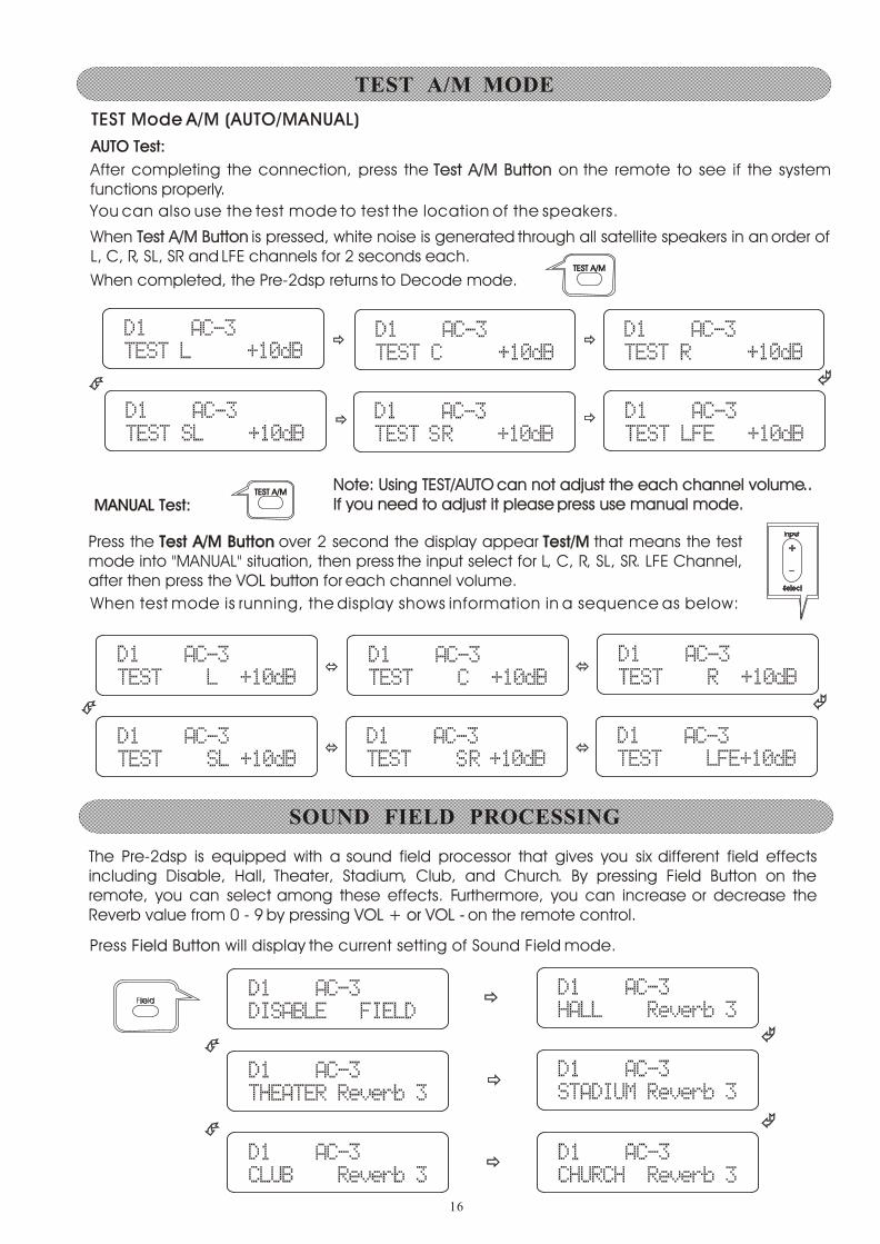
TEST Mode A/M (AUTO/MANUAL)TEST Mode A/M (AUTO/MANUAL)
After completing the connection, press the Test A/M Button on the remote to see if the system functions properly.
Test A/M Button
You can also use the test mode to test the location of the speakers.
When Test A/M Button is pressed, white noise is generated through all satellite speakers in an order of L, C, R, SL, SR and LFE channels for 2 seconds each.
Test A/M Button
When test mode is running, the display shows information in a sequence as below:
When completed, the Pre-2dsp returns to Decode mode.
AUTO Test:AUTO Test:
MANUAL Test:MANUAL Test:
Press the Test A/M Button over 2 second the display appear Test/M that means the test mode into "MANUAL" situation, then press the input select for L, C, R, SL, SR. LFE Channel, after then press the VOL button for each channel volume.
Test A/M Button Test/M
VOL button
The Pre-2dsp is equipped with a sound field processor that gives you six different field effects including Disable, Hall, Theater, Stadium, Club, and Church. By pressing Field Button on the remote, you can select among these effects. Furthermore, you can increase or decrease the Reverb value from 0 - 9 by pressing VOL + or VOL - on the remote control.VOL + or VOL -
Press Field Button will display the current setting of Sound Field mode.Field Button
TEST A/MTEST A/M
TEST A/MTEST A/M
Note: Using TEST/AUTO can not adjust the each channel volume.. If you need to adjust it please press use manual mode.Note: Using TEST/AUTO can not adjust the each channel volume.. If you need to adjust it please press use manual mode.
16
TEST A/M MODE
SOUND FIELD PROCESSING
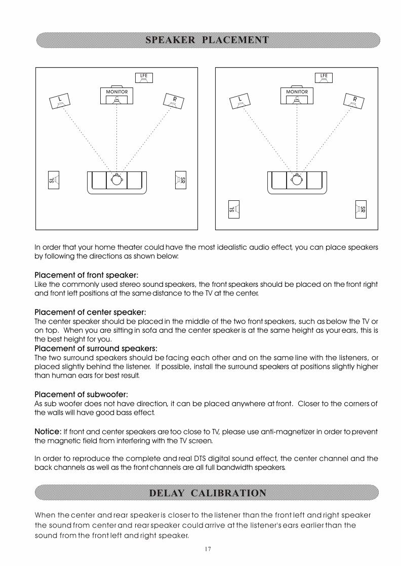
When the center and rear speaker is closer to the listener than the front left and right speaker
the sound from center and rear speaker could arrive at the listener's ears earlier than the
sound from the front left and right speaker.
R
LFE
L
SL
SR
C
MONITOR
R
LFE
L
SL
SR
C
MONITOR
In order that your home theater could have the most idealistic audio effect, you can place speakers by following the directions as shown below:
Placement of front speaker:Like the commonly used stereo sound speakers, the front speakers should be placed on the front right and front left positions at the same distance to the TV at the center.
Placement of center speaker:The center speaker should be placed in the middle of the two front speakers, such as below the TV or on top. When you are sitting in sofa and the center speaker is at the same height as your ears, this is the best height for you.
Placement of surround speakers:The two surround speakers should be facing each other and on the same line with the listeners, or placed slightly behind the listener. If possible, install the surround speakers at positions slightly higher than human ears for best result.
Placement of subwoofer:As sub woofer does not have direction, it can be placed anywhere at front. Closer to the corners of the walls will have good bass effect.
Notice: If front and center speakers are too close to TV, please use anti-magnetizer in order to prevent the magnetic field from interfering with the TV screen.
In order to reproduce the complete and real DTS digital sound effect, the center channel and the back channels as well as the front channels are all full bandwidth speakers.
17
DELAY CALIBRATION
SPEAKER PLACEMENT

In this reason, the sound imaging not as sharp and stable as it could be. For audible improvement, the sound from center speaker could be delayed with the center delay time setting to synchronize the sound from the front and the center speaker and the sound from the rear speaker could be also delayed with the rear delay time setting so that the sound from the front and the rear speakers will be heard at the same time.The optimum delay time depends on the speaker placement in your room. It is adjustable in DTS Dolby digital and Dolby Pro Logic modes only.
Delay CalibrationDelay Calibration
Press DELAY Button to select the length of delay time for SL/SR/C channels. Repeatedly pressing DELAY Button will allow you to select among 3 surround speakers (SL, SR, C.)
The delay time range for SL/SR is 0 to 15 ms and 0 to 5 ms for center.
Adjust delay time on selected channel by pressing input/sel on the remote control.
Press the Delay Button will display the current delay time for channel LS.Delay Button
Press the Delay Button again will circle next channelDelay Button
Press INPUT + or INPUT - button will increase or decrease the delay time for current channel.INPUT + INPUT -
Delay CalibrationDelay Calibration
Press Delay Button to select the length of delay time for SL/SR/C channels, Repeatedly pressing Delay Button will allow you to select among 3 Surround speakers (SL, SR, C.)
Delay ButtonDelay Button
The delay time range for SL/SR is 0 to 15 ms and 0 to 5 ms for center.
Adjust delay time on selected channel by pressing Input + or input - on the remote control. Input + input -
Exit
Exit
18
In Dolby Digital mode adjusting delay time of the speakers.In Dolby Digital mode adjusting delay time of the speakers.
In the Dolby Digital mode, the optimum performance of your system occurs when the sound from all five speakers arrives at your primary listening position at the same time.If all speakers are equidistant from the main listening position, set the following delay.Center delay time: 0 mS, Rear delay time: 0 mS If the center speaker is closer to your prime listening position than the average distance to the left and right main speakers add 1 mS of center channel delay for each foot of difference. The maximum is 5 mS.If the surround speakers are closer to your main listening position than the main left and right speakers add 5 mS of surround channel delay for each 5 feet of difference. The maximum is 15 mS.
Note: The propagation speed of sound is 34 cm /mili-second (/ms).
TIME DELAY ADJUSTMENT ON CENTER CHANNEL SPEAKER
TIME DELAY ADJUSTMENT ON SURROUND SPEAKER
Surround Speaker DelaySurround Speaker Delay
Delay calibration for the surround speaker is necessary when the surround speakers are placed quite closed to the listener. The type of placement would probably ruin the sound quality of Your movie. To correct this problem, press Delay Button repeatedly until SL/SR appear on the display. Increase the time delay of the surround speakers by pressing input + until you are able to hear a 3D sound effect coming from surround speaker.
Delay Button
Press Delay Button again will circle to next channel. Delay Button
Press Input + or Input - wil l increase or decrease the delay time for current channel.Input + Input -
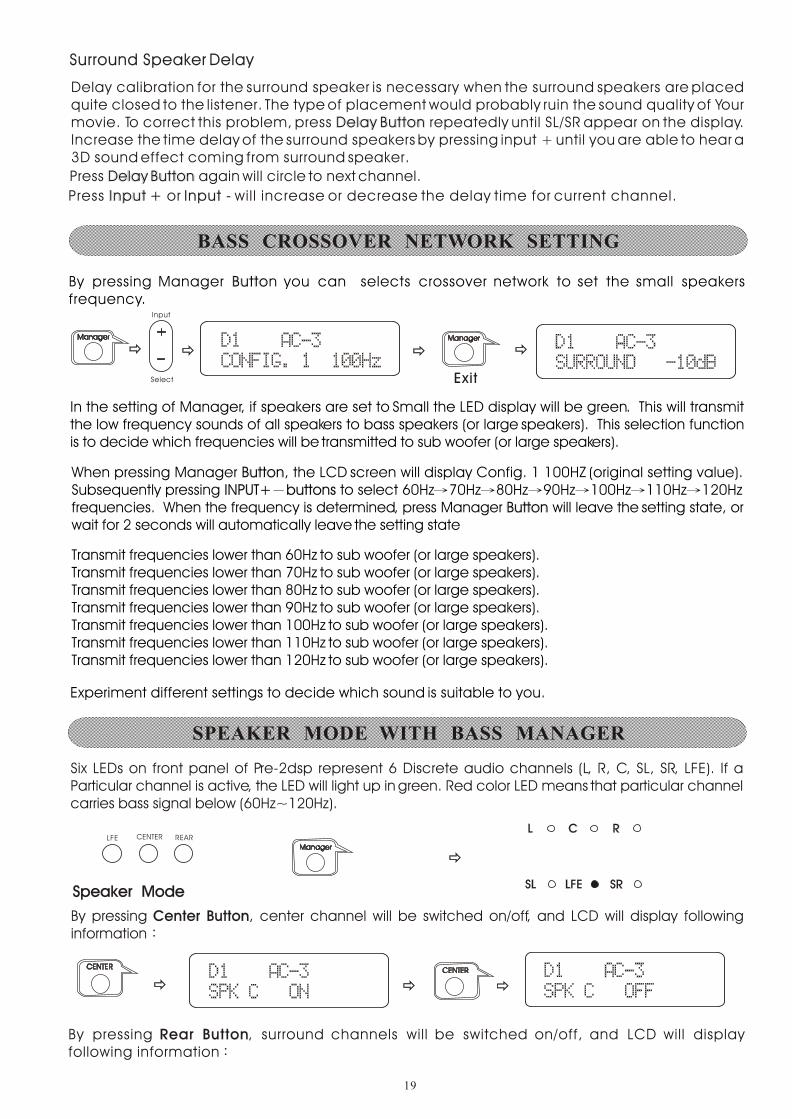
By pressing Manager Button you can selects crossover network to set the small speakers frequency.
Butto
In the setting of Manager, if speakers are set to Small the LED display will be green. This will transmit the low frequency sounds of all speakers to bass speakers (or large speakers). This selection function is to decide which frequencies will be transmitted to sub woofer (or large speakers).
When pressing Manager Button, the LCD screen will display Config. 1 100HZ (original setting value). Subsequently pressing INPUT+ buttons to select 60Hz 70Hz 80Hz 90Hz 100Hz 110Hz 120Hz frequencies. When the frequency is determined, press Manager Button will leave the setting state, or wait for 2 seconds will automatically leave the setting state
ButtonINPUT+ buttons
Button
Transmit frequencies lower than 60Hz to sub woofer (or large speakers).Transmit frequencies lower than 70Hz to sub woofer (or large speakers).Transmit frequencies lower than 80Hz to sub woofer (or large speakers).Transmit frequencies lower than 90Hz to sub woofer (or large speakers).Transmit frequencies lower than 100Hz to sub woofer (or large speakers).Transmit frequencies lower than 110Hz to sub woofer (or large speakers).Transmit frequencies lower than 120Hz to sub woofer (or large speakers).
Exit
Experiment different settings to decide which sound is suitable to you.
19
Six LEDs on front panel of Pre-2dsp represent 6 Discrete audio channels (L, R, C, SL, SR, LFE). If a Particular channel is active, the LED will light up in green. Red color LED means that particular channel carries bass signal below (60Hz~120Hz).
Speaker ModeSpeaker Mode
By pressing Center Button, center channel will be switched on/off, and LCD will display following information
Center Button
By pressing Rear Button, surround channels will be switched on/off, and LCD will display following information
Rear Button
SPEAKER MODE WITH BASS MANAGER
BASS CROSSOVER NETWORK SETTING

By pressing LFE Button, subwoofer will be switched on/off, and LCD will display following informationLFE Button
Manager (Bass Manager)Manager (Bass Manager)
By pressing BASS MANAGER Button,you can select among three different settings of Bass Config. 1, Bass Config. 2 and Bass Config. 3. These selections will feed the bass signal below 120Hz to different speakers.
Bass Config. 1Bass Config. 1
With this setting, bass signal below 120Hz will be sent to subwoofer; LEDs on front panel of Pre-2dsp indicating LFE SW will be in red, and LCD will show the following information
Bass Config. 2Bass Config. 2With this setting, bass signal below (60Hz, 70Hz, 80Hz, 90Hz, 100Hz, 110Hz, 120Hz) will be sent to front left speaker, front right speaker and subwoofer; LEDs on front panel of Pre-2DSP indicating L/R/LFE will be in red, and LCD will show the following information:
20
Bass Config. 3Bass Config. 3With this setting, bass signal below 120Hz will be sent to all speakers; LEDs on front panel of Pre-2DSP Indicating L/C/R/SL/SR/LFE channels will be in red.
With this setting, bass signal below 120Hz will be sent to all speakers; LEDs on front panel of Pre-2dsp Indicating L/C/R/SL/SR/LFE channels will be in red.
By pressing Prologic Button consecutively, you can switch among 5 different Prologic II modes that optimize the effects in accordance with your source and speaker configuration. The four modes are MOVIE, MUSIC, MUSIC with Panorama and MATRIX. With two channel sources, these four modes will create surround channels comparable to Dolby 5.1.
MOVIEThis mode is suitable for movies, especially those recorded in Dolby Surround.
PROLOGIC II MODE
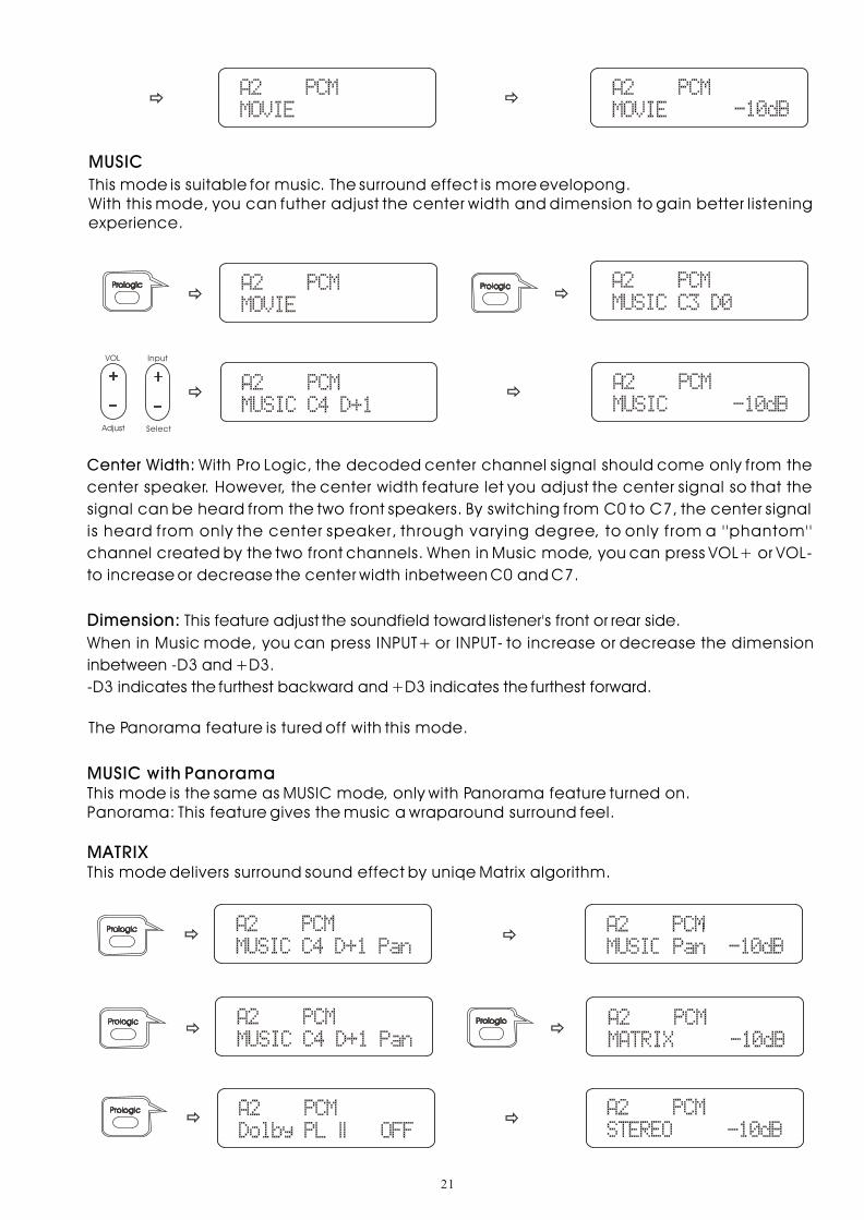
Center Width: With Pro Logic, the decoded center channel signal should come only from the
center speaker. However, the center width feature let you adjust the center signal so that the
signal can be heard from the two front speakers. By switching from C0 to C7, the center signal
is heard from only the center speaker, through varying degree, to only f rom a ' 'phantom''
channel created by the two front channels. When in Music mode, you can press VOL+ or VOL-
to increase or decrease the center width inbetween C0 and C7.
Dimension: This feature adjust the soundfield toward listener's front or rear side.
When in Music mode, you can press INPUT+ or INPUT- to increase or decrease the dimension
inbetween -D3 and +D3.
-D3 indicates the furthest backward and +D3 indicates the furthest forward.
The Panorama feature is tured off with this mode.
MUSIC with PanoramaThis mode is the same as MUSIC mode, only with Panorama feature turned on.Panorama: This feature gives the music a wraparound surround feel.
MATRIXThis mode delivers surround sound effect by uniqe Matrix algorithm.
21
MUSIC
This mode is suitable for music. The surround effect is more evelopong.With this mode, you can futher adjust the center width and dimension to gain better listening experience.
22
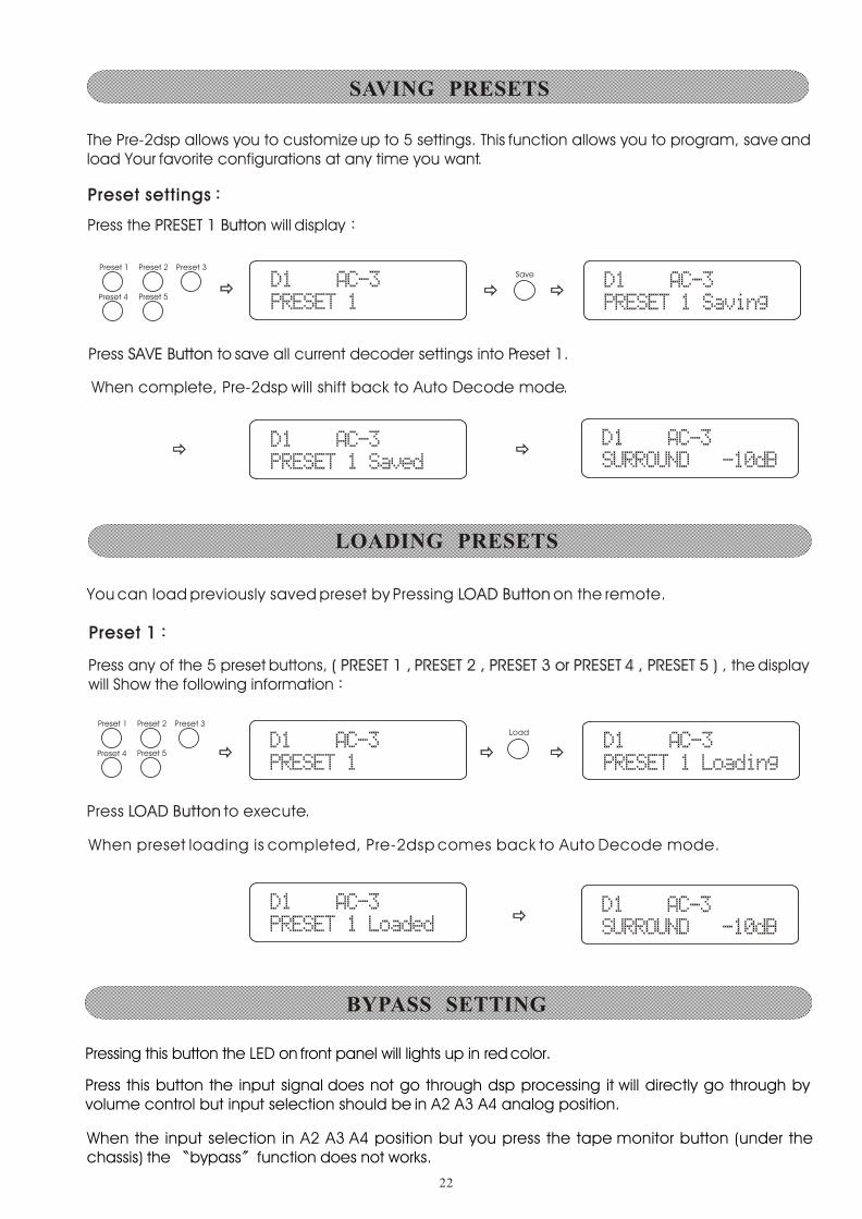
The Pre-2dsp allows you to customize up to 5 settings. This function allows you to program, save and load Your favorite configurations at any time you want.
Preset settingsPreset settings
Press the PRESET 1 Button will display PRESET 1 Button
Press SAVE Button to save all current decoder settings into Preset 1.SAVE Button
When complete, Pre-2dsp will shift back to Auto Decode mode.
You can load previously saved preset by Pressing LOAD Button on the remote. LOAD Button
Preset 1Preset 1
Press any of the 5 preset buttons, ( PRESET 1 , PRESET 2 , PRESET 3 or PRESET 4 , PRESET 5 ) , the display will Show the following information
( PRESET 1 , PRESET 2 , PRESET 3 or PRESET 4 , PRESET 5 )
Press LOAD Button to execute.LOAD Button
When preset loading is completed, Pre-2dsp comes back to Auto Decode mode.
Press this button the input signal does not go through dsp processing it will directly go through by volume control but input selection should be in A2 A3 A4 analog position.
Pressing this button the LED on front panel will lights up in red color.
When the input selection in A2 A3 A4 position but you press the tape monitor button (under the chassis) the bypass function does not works.
SAVING PRESETS
LOADING PRESETS
BYPASS SETTING
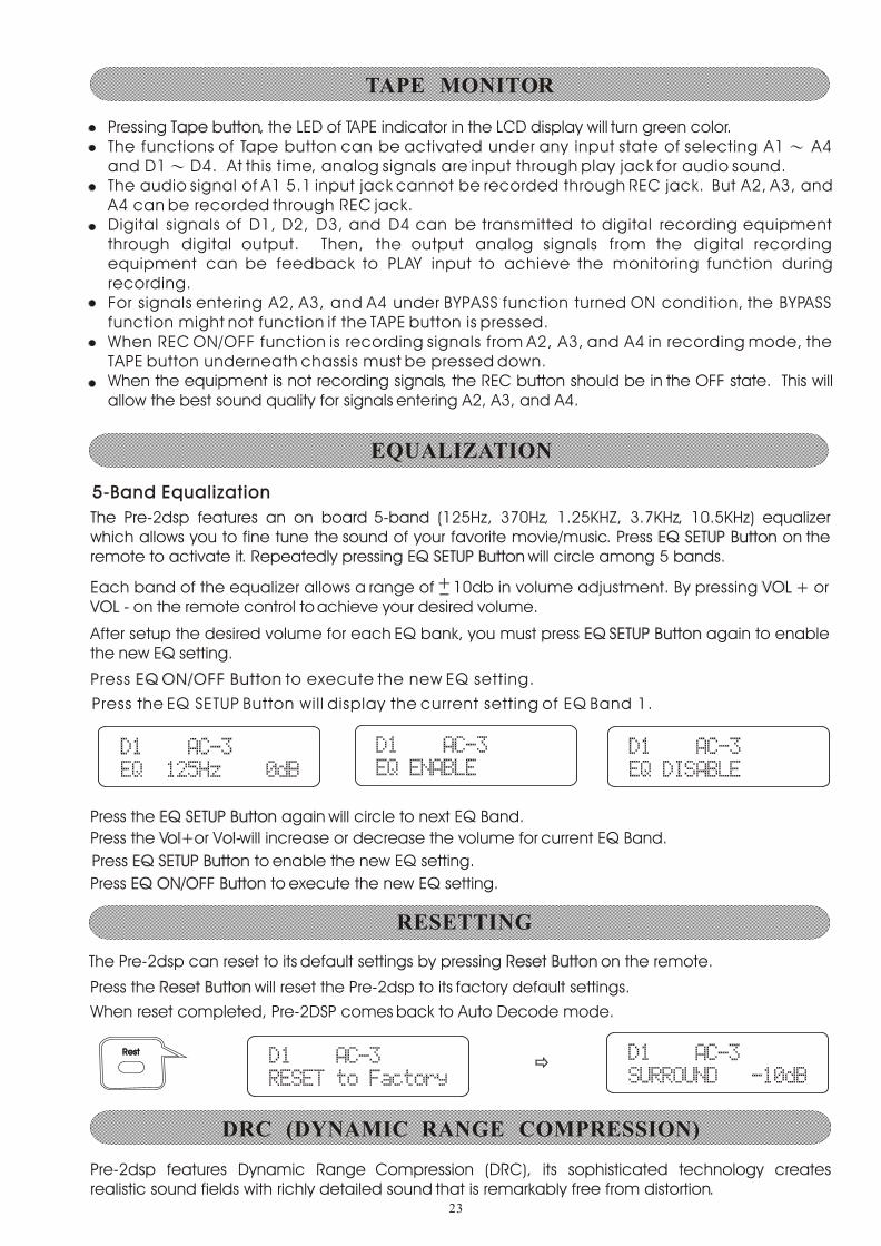
Pressing Tape button, the LED of TAPE indicator in the LCD display will turn green color.The functions of Tape button can be activated under any input state of selecting A1 A4 and D1 D4. At this time, analog signals are input through play jack for audio sound.The audio signal of A1 5.1 input jack cannot be recorded through REC jack. But A2, A3, and A4 can be recorded through REC jack.Digital signals of D1, D2, D3, and D4 can be transmitted to digital recording equipment through digital output. Then, the output analog signals from the digital recording equipment can be feedback to PLAY input to achieve the monitoring function during recording.For signals entering A2, A3, and A4 under BYPASS function turned ON condition, the BYPASS function might not function if the TAPE button is pressed.When REC ON/OFF function is recording signals from A2, A3, and A4 in recording mode, the TAPE button underneath chassis must be pressed down.When the equipment is not recording signals, the REC button should be in the OFF state. This will allow the best sound quality for signals entering A2, A3, and A4.
Tape button
23
5-Band Equalization5-Band Equalization
The Pre-2dsp features an on board 5-band (125Hz, 370Hz, 1.25KHZ, 3.7KHz, 10.5KHz) equalizer which allows you to fine tune the sound of your favorite movie/music. Press EQ SETUP Button on the remote to activate it. Repeatedly pressing EQ SETUP Button will circle among 5 bands.
EQ SETUP ButtonQ SETUP Button
Each band of the equalizer allows a range of 10db in volume adjustment. By pressing VOL + or VOL - on the remote control to achieve your desired volume.
VOL + VOL -
After setup the desired volume for each EQ bank, you must press EQ SETUP Button again to enable the new EQ setting.
EQ SETUP Button
Press EQ ON/OFF Button to execute the new EQ setting.EQ ON/OFF Button
Press the EQ SETUP Button wil l display the current setting of EQ Band 1.
Press the EQ SETUP Button again will circle to next EQ Band.EQ SETUP Button
Press the Vol+or Vol-will increase or decrease the volume for current EQ Band.Vol+ Vol-
Press EQ SETUP Button to enable the new EQ setting.EQ SETUP Button
Press EQ ON/OFF Button to execute the new EQ setting. EQ ON/OFF Button
The Pre-2dsp can reset to its default settings by pressing Reset Button on the remote.Reset Button
Press the Reset Button will reset the Pre-2dsp to its factory default settings.Reset Button
When reset completed, Pre-2DSP comes back to Auto Decode mode.
RestRest
Pre-2dsp features Dynamic Range Compression (DRC), its sophisticated technology creates realistic sound fields with richly detailed sound that is remarkably free from distortion.
++__
DRC (DYNAMIC RANGE COMPRESSION)
RESETTING
EQUALIZATION
TAPE MONITOR
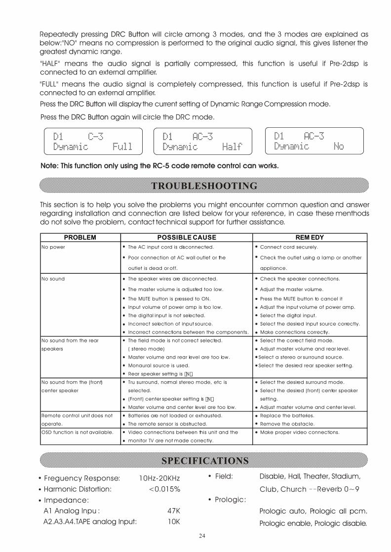
Repeatedly pressing DRC Button will circle among 3 modes, and the 3 modes are explained as below:"NO" means no compression is performed to the original audio signal, this gives listener the greatest dynamic range.
DRC Button
"HALF" means the audio signal is partially compressed, this function is useful if Pre-2dsp is connected to an external amplifier.
"FULL" means the audio signal is completely compressed, this function is useful if Pre-2dsp is connected to an external amplifier.
Press the DRC Button will display the current setting of Dynamic Range Compression mode.DRC Button
Press the DRC Button again will circle the DRC mode. DRC Button
Note: This function only using the RC-5 code remote control can works.Note: This function only using the RC-5 code remote control can works.
24
This section is to help you solve the problems you might encounter common question and answer regarding installation and connection are listed below for your reference, in case these menthods do not solve the problem, contact technical support for further assistance.
Freguency Response: 10Hz-20KHz
Harmonic Distortion: <0.015%
Field: Disable, Hall, Theater, Stadium,
Club, Church Reverb 0~9
Impedance:
A1 Analog lnpu : 47K
Prologic:
Prologic auto, Prologic all pcm.
A2.A3.A4.TAPE analog lnput: 10K Prologic enable, Prologic disable.
PROBLEM POSSIBLE CAUSE REM EDY
No power The AC input cord is disconnected. Connect cord securely.
Poor connection at AC wall outlet or the Check the outlet using a lamp or another
outlet is dead or off. appliance.
No sound The speaker wires are disconnected. Check the speaker connections.
The master volume is adjusted too low. Adjust the master volume.
The MUTE button is pressed to ON. Press the MUTE button to cancel it
Input volume of power amp is too low. Adjust the input volume of power amp.
The digital input is not selected. Select the digital input.
Incorrect selection of input source. Select the desired input source correctly.
Incorrect connections between the components. Make connections correctly.
No sound from the rear The field mode is not correct selected. Select the correct field mode.
speakers ( stereo mode) Adjust master volume and rear level.
Master volume and rear level are too low. Select a stereo or surround source.
Monaural source is used. Select the desired rear speaker setting.
Rear speaker setting is “N”.
No sound from the (front) Tru surround, normal stereo mode, etc is Select the desired surround mode.
center speaker selected. Select the desired (front) center speaker
(Front) center speaker setting is “N”. setting.
Master volume and center level are too low. Adjust master volume and center level.
Remote control unit does not Batteries are not loaded or exhausted. Replace the batteries.
operate. The remote sensor is obstructed. Remove the obstacle.
OSD function is not available. Video connections between this unit and the Make proper video connections.
monitor TV are not made correctly.
TROUBLESHOOTING
SPECIFICATIONS

25
For best sonic results, correct orientation of the AC plug is important. The prong with the red dot
should be connected to the "hot" connection of your wall socket.
Do not place Pre-2DSP on a glass shelf. If you really must, use "Altuglass" on the shelf. We do
highly recommend placement on wood or granite.
Check the quality of your AC cords and power strips (unlighted power strips are preferred).
For best results, the Pre-2DSP should initially be broken in with 30 hours of play. A warm up of 1
hours is best whenever the unit has been switched off.
In order to maintain good sonic quality, it is recommended that you do not stack the Pre-2DSP
and the Power amplifier on top of each other. The best is to place them separated, one on the
left and the other on the right. This is to ensure that the electromagnetic interference emitting
from the transformers of the high-current power amplifier will not affect the Pre-2DSP, and thus
causes deterioration in the overall sonic quality.
YBA GLASS, CRISTAL or DIAMOND interconnect & speaker cables will give the best sonic result.
Audio RefinementAudio Refinement
Nous restons a votre disposition pour toutrenseignement complementaire
F-91440 BURES-SUR-YVETTE - FRANCE
Tel:(33) 01 60 12 51 00 Fax:(33) 01 60 12 50 60
BP-12
PHLOX ELECTRONIQUE
It is preferable to leave your Pre-2DSP permanently Standby (Power indicator is red). The power
consumption is low and the sonic benefits are high.
RECOMMENDATIONS
Digital lnput: 0.5V P-P /75
Signal/Noise Ratio: 90dB
Video Input Impedance: 1.0V P-P /75
Component Video:
R-Y signal, B-Y signal: 0.5V P-P /75
Power Consumption: 45W
Function Crontrols:
Volume: -80 ~ +10dB
Balance: L,C,R,SL,SR,LFE, -12dB~0dB
Delay Time : Center 0ms ~ 5ms
Test: L/C/R/SL/SR/LFE
(125Hz, 370Hz, 1.25KHz, 3.7KHz,10.5K)
Preset Function: P1~ P5 Save/Load
Management:
Speaker Controls: SL/SR on/off
DRC: Fall, Half & No
Y-Signal: 1.0V P-P /75
Delay Time : Rear (SR,SL) 0ms~15ms
EQ Setup : EQ Band 1~5 _+10dB
Config1. Config2. Config3. Config OFF
C on/off
L/R on/off
Bass Crossover:
80Hz, 90Hz,100Hz, 110Hz.120Hz
Dimensions(mm): 442W*320D*105H
Weight: 4.5kg
Note: Design and specifications are subject to change without notice for improvements.