pre-assembled radiant control panel installation …
TRANSCRIPT
FloorHeat°
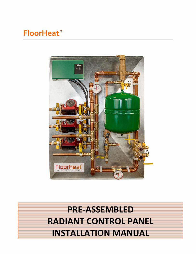
PRE-ASSEMBLED
RADIANT CONTROL PANEL
INSTALLATION MANUAL

Thank you
for purchasing this radiant control panel assembly.
Following are some important notes that will make the
installation successful.
• Read through the entire manual before starting installation
• Do NOT plug in the power cord until the panel is installed,
connected, and the fluid has been filled.
• If there has been damage in shipment, please call 888-265-5455
for troubleshooting, returns, and replacement parts. Do NOT
return the panel to the store.
• Installation must be performed by a qualified person in
accordance with national and local codes and standards.
• All electrical connections must be installed by a licensed
electrician.
• This generic manual covers several different versions of control
panels. Please refer to the plumbing schematic in the appendix
to specific plumbing information.
• Failure to follow these instructions may result in fire, electrical
shock, property damage, personal injury or death.
1. Planning the installation. The control panel should be mounted on a wall or permanent vertical
surface near the boiler for convenient plumbing and wiring. It should be mounted
at a convenient height to ease installation and maintenance.
2. Panel Mounting. Once the location has been determined, drill (2) ¼" diameter holes on each
of the four panel mounting flanges. Install a 1x wood cleat, 28" long, to the
mounting surface where the top panel flange will be mounted. Make sure the
cleat is level. Using the cleat to help support the panel, install the appropriate
mounting screws. The screws should be at least 1-1/2" long.
3. Boiler supply and return lines. Using 1" type L copper tubing, route the supply and return lines to the
boiler. Refer to the appropriate panel schematic in the appendix and the boiler
manufacture's plumbing schematic for specific information. As a general
guideline maintain the shortest possible plumbing distance between the panel
and boiler while minimizing the use of the 90 degree fittings. Every fitting
increases flow resistance, reducing heat transfer. Also, all tubing runs must be
properly supported. Use Uni-Strut channels and clamps or equivalent for tube
support. Note additional plumbing devices may be needed such as a low water
cut off, circulator, ball valves, etc. Refer to the boiler plumbing schematic.
INSTALLATION

4. Manifold transmission lines. Using ¾" type L copper tubing or ¾" oxygen barrier PEX tubing, route the
transmission lines from the control panel to the zone manifold(s). Referring to
the appropriate panel schematic in the appendix, note the location of the supply
and return lines. Customarily, the upper zone manifold is the return to bring any
trapped air back to the control for purging. Use the same guideline for tube
routing as the boiler lines, minimize line lengths, minimize 90 degree fittings, and
properly support lines.
5. Water makeup line.
Using ½" type L or M copper tubing, connect the "cold water supply" line
on the control panel to the suitable clean water source. Do NOT turn on water
yet.
6. Check expansion tank pressure. Remove the plastic cap on the expansion tank, and using a standard tire
pressure gauge, check tank pressure. It should be about 10 to 12 psi. Add
pressure if necessary.
NOTE:
The standard control panels are designed for installations where the fluid
temperatures should never go below freezing. For seasonal or snow melt
installations, different control panels are needed for the use of anti-freeze
solutions. The best fluid for radiant heating systems is clean water. The
water, however, does need to have a minimum pH of 5 and low hardness.
Treat water if necessary before proceeding.
The tank pressure should be checked annually for proper system operation.
This is done by closing the expansion tank ball valve, removing drain cap,
attaching a drain hose and opening the drain valve. A small amount of
water/pressure will come out. This isolates the tank from the system and
removes any residual system pressure. Check the tank pressure and add pressure
if necessary. Close drain valve, disconnect hose, replace cap, and open expansion
ball valve. The system is ready to use.
7. Initial system fill. Open all of the ball valves to the zone manifolds and boiler. There is a little
brass cap on the top of the air eliminator on the control panel. Loosen the cap
slightly to allow air in the system to be purged. Open the water supply ball valves.
This operation will fill most of the system with water and should take only a few
minutes. Once the system pressure on the control panel is about 15 to 20 psi, the
pressure reducing valve will automatically shut off the water supply. Shut off the
water supply ball valve and close the air eliminator vent cap.
8. System purge. It is important that all air is removed from the system before start up. Air
in the system can cause corrosion of components, noise, and cold zones. A
properly purged system will be almost silent in operation. Referring to the
appropriate panel schematic in the appendix, there are two purge/fill diagrams in
the upper right hand corner. These diagrams show the proper ball valve
orientation to first purge the low temperature zone manifold side and then purge
the boiler side last.
A simple setup to use for system purge is a high-flow submersible pump, 5-
gallon bucket, (2) 1" hoses about 6' long, and the necessary fittings. Plumb the
submersible pump discharge with one of the 1" hoses into the in ball drain port as
noted on the schematic. Plumb the second 1" hose to the out ball drain port as
noted on the schematic. This second hose returns to the 5-gallon bucket. With
the pump in the bucket, fill the bucket with clean water.
Each of the ball drain valves have two ball valves. The ball valve where the
hose attaches, simply opens and closes the line. The second ball is actually a 3-
way valve, which can direct water flow straight through or one direction or the
other. The ball valve handle decal indicates flow direction.
To purge the low temperature side, orient the 3-way valve as shown on the
purge/fill diagram. Plug in the submersible pump and slowly open both of the
inlet ball valves on the ball drain valves. Water should be now flowing through
the system and returning to the 5-gallon bucket. The return water will have a
considerable amount air coming out as well. Continue running the pump until
most of the air is removed. This may be several minutes. Make sure the water
level in the bucket does not get too low and add water as needed.
Now each zone and loop must to purged separately to insure all air is
removed. Slowly shut the ball valves to all the zone manifolds except for one.
Now all the water flow should be going through the one open zone manifold. At
the zone supply manifold, slowly close all the loop-ball valves on the supply
except one loop. Now all water flow will be flowing through a single loop.
Continue running the pump until the return water is free of air bubbles. Slowly
open the next loop ball valve and close the first loop ball valve. This method of
opening and closing loop ball valves isolates each loop forcing all air from the
system. Once a loop manifold is complete, open all loop ball valves. At the
control panel slowing open the next zone loop ball valve and close the previous.
Proceed as before opening and closing loop zones at the supply manifold until all
air is eliminated. When all zones and loops have been purged of air, open all zone
and loop ball valves. Water should continue to be flowing through the system.
Quickly close both of inlet ball valves on the ball drain valves. Turn off the pump.
The low temperature air purge is now complete.
To purge the boiler side, reverse the flow of the drain valves 3-way ball
valves as noted on the second purge/fill diagram. Make sure any air vent on the

boiler is closed. Plug in the submersible pump and slowly open both inlet ball
valves on the ball drain valves. Water should now flow through the boiler and
return water and air to the bucket. When the return line is free of air bubbles,
quickly close both inlet ball valves on the ball drain valves. Turn off the pump.
The system is now purged of air.
Disconnect the purge line and replace the drain valves caps. Position the
drain valves 3-way ball valves to the flow through position. Loosen the cap on the
air eliminator vent and open any vent on the boiler. Open the supply water ball
valve. A small amount of water will be added to increase the system pressure to
15 to 20 psi. The system is now completely filled.
9. Connect thermostat and boiler control wiring. Open the green control box. At the top right is a terminal strip label with
zone 1, zone 2, etc. Using at least 3-conductor (one conductor is a spare) solid
thermostat wire, connect the appropriate zone terminal to the room thermostat.
Make sure to route the wires through the rubber grommet(s) at the top of the
control box.
At the lower left are the X1 and X2 terminals. These connect to the boiler
control circuit. Depending upon local codes additional devices may be wired in
series such as a low water cutout, high temp limit switches, etc. Use at least 3-
conductor (one conductor is spare) solid thermostat wire to make the connection.
Make sure to route the wires through the rubber grommet at the bottom left side
of the control box. Replace the control box cover.
10. Connect to line voltage. Depending upon local codes, this could as simple as plugging in the
attached cord into an outlet or the cord may need to be hardwired into a junction
box.
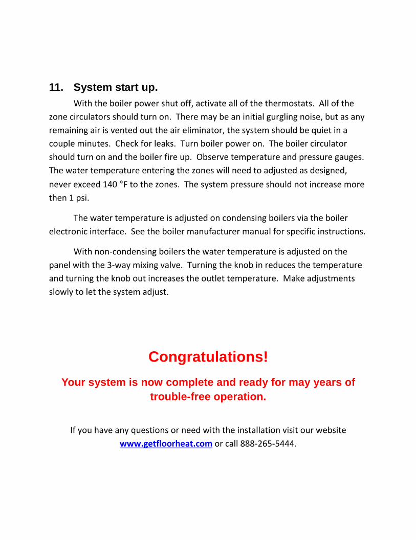
11. System start up. With the boiler power shut off, activate all of the thermostats. All of the
zone circulators should turn on. There may be an initial gurgling noise, but as any
remaining air is vented out the air eliminator, the system should be quiet in a
couple minutes. Check for leaks. Turn boiler power on. The boiler circulator
should turn on and the boiler fire up. Observe temperature and pressure gauges.
The water temperature entering the zones will need to adjusted as designed,
never exceed 140 °F to the zones. The system pressure should not increase more
then 1 psi.
The water temperature is adjusted on condensing boilers via the boiler
electronic interface. See the boiler manufacturer manual for specific instructions.
With non-condensing boilers the water temperature is adjusted on the
panel with the 3-way mixing valve. Turning the knob in reduces the temperature
and turning the knob out increases the outlet temperature. Make adjustments
slowly to let the system adjust.
Congratulations!
Your system is now complete and ready for may years of trouble-free operation.
If you have any questions or need with the installation visit our website
www.getfloorheat.com or call 888-265-5444.

Appendix
1-4 Zone Control Panel for Condensing Boiler

5-8 Zone Control Panel for Condensing Boiler
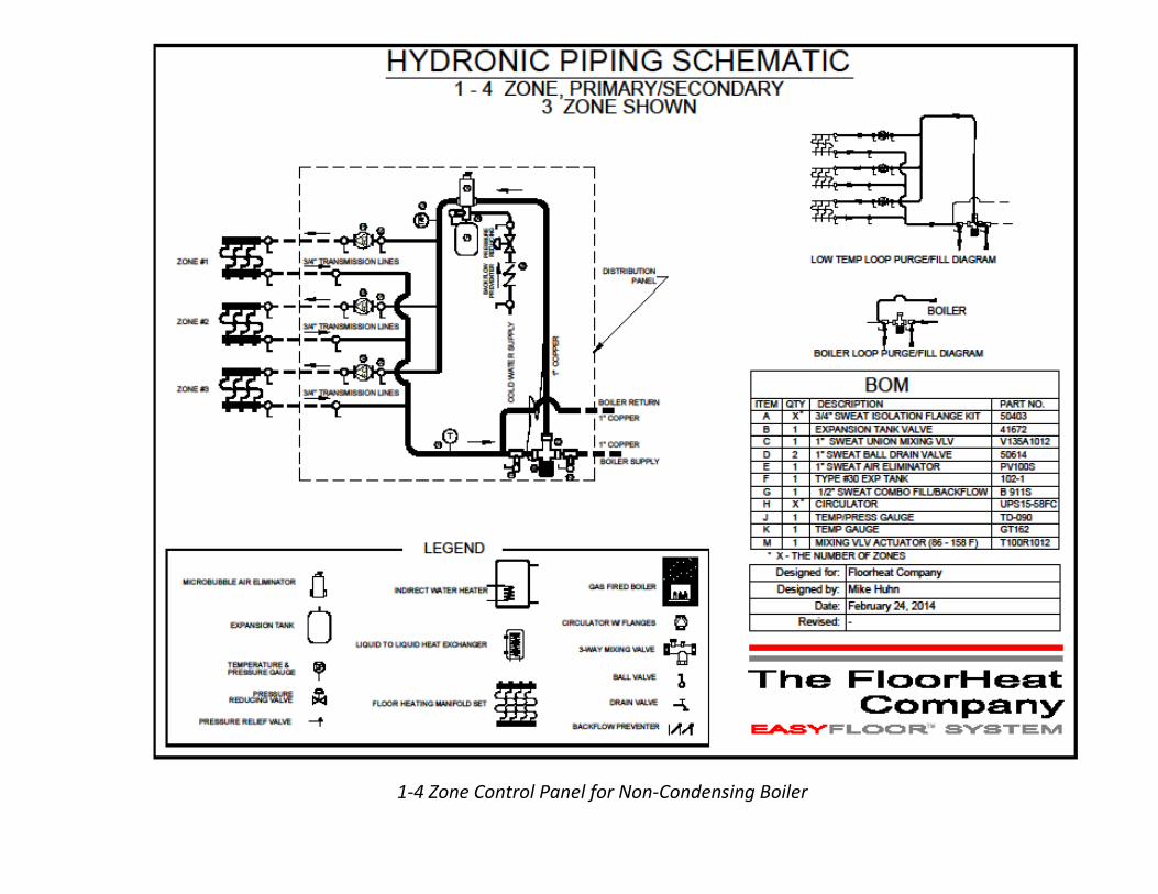
1-4 Zone Control Panel for Non-Condensing Boiler
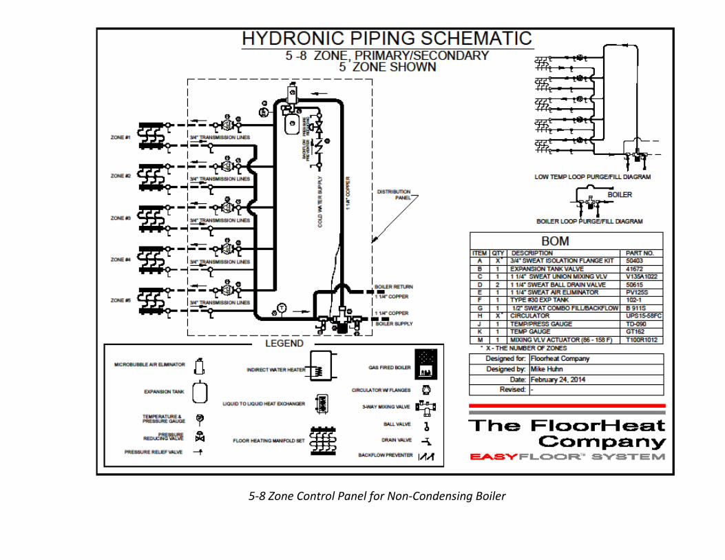
5-8 Zone Control Panel for Non-Condensing Boiler