pre-combustion with physical absorption with physical absorption ... sulphur absorption clean gas...
TRANSCRIPT

Pre-combustion with Physical Absorption
E.R. van Selow
R.W. van den Brink
Presented at the 2nd ICEPE, 18 November 2011, Frankfurt, Germany
ECN-L--11-126 November 2011

www.ecn.nl
Pre-combustion with Physical Absorption
Ed van Selow, Ruud van den Brink2nd ICEPE, 2011

2

IGCC with carbon removal
Oxygen
Gas treatment
Sulphur absorption
Clean gas shiftsteam
CO2 absorption
H2Pulverised
Coal
Gasifier
Gas treatment
3
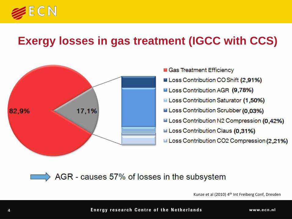
Exergy losses in gas treatment (IGCC with CCS)
Kunze et al (2010) 4th Int Freiberg Conf, Dresden
4

IGCC with carbon removal
Oxygen
Gas treatment
Sulphur absorption
Clean gas shiftsteam
CO2 absorption
H2Pulverised
Coal
Gasifier
Gas treatment
Sour vs sweet WGSExisting sour gas treating technologies
Chemical, physical, hybrid absorbentsPhysical sorbents and processes
DevelopmentsAdvanced solventsAdvanced shiftLow steam sour shiftSour PSAHigh-temperature gas clean-upReaction/separation integration: SEWGSPilot at Buggenum IGCC
5

Sour vs sweet WGS
6

Sour vs sweet (clean) WGS arrangement
Sour Shift Retains steam Hydrolysis COS Operates in a wider temperature range
Sweet ShiftMore selective sulphur removal Smaller reactorCheaper catalyst
7

Existing sour gas treating processes
8

Gas treatment requirements (example)
Selective sulphur removal
syngas De-S syngas
CO2+H2S
H2S+COS < 30 ppm
H2S > 20%
Sulphur + carbon
removal
syngas H2
CO2+H2S
H2S+COS < 30 ppm, CO+CO2 < 3%
Selectivesulphur +
carbon removal
syngas H2
CO2
H2S+COS < 30 ppm, CO+CO2 < 3%
H2S > 20%CO2+H2S
H2S < 200 ppm
9

Chemical solvents (amines) Mixed (hybrid) solvents Physical solvents
More efficient at low pressure More efficient at high
pressure
Sulphur removal 98% Very high sulphur recoveries
can be achieved.
Sulphur removal 99%
High selectivity for H2S
Higher energy penalty due to
steam stripping
Higher investment costs
May form heat-stable salts Stable solvent
Low coabsorption Remove additional impurities
such as HCN, NH3
Co-adsorption of H2
Selecting the absorbent
10

Selecting the absorption process
Selection of suitable CO2
absorption process:
a) Physical solvent + amine
b) Physical solvent, physical solvent +
amine or activated hot K2CO3
c) Physical solvent
d) Physical solvent or activated hot K2CO3
e) Activated hot K2CO3 or concentrated
amine
f) Activated hot K2CO3 or amine
g) Amine
Trade-off at pCO2 ~ 6 bar between
solvent loading/recirculation (lean vs.
rich) and equipment sizing
Ullmann’s Encyclopedia
11
330 MWe NGCC Power Plant.
Based on January 2006 prices.
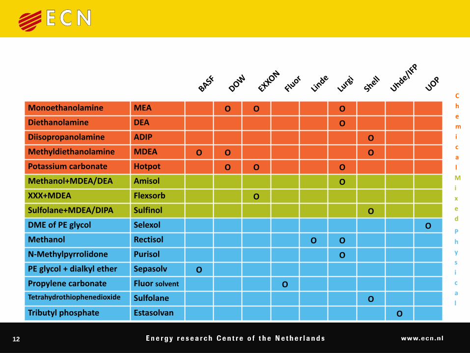
Monoethanolamine MEA O O O
Diethanolamine DEA O
Diisopropanolamine ADIP O
Methyldiethanolamine MDEA O O O
Potassium carbonate Hotpot O O O
Methanol+MDEA/DEA Amisol O
XXX+MDEA Flexsorb O
Sulfolane+MDEA/DIPA Sulfinol O
DME of PE glycol Selexol O
Methanol Rectisol O O
N-Methylpyrrolidone Purisol O
PE glycol + dialkyl ether Sepasolv O
Propylene carbonate Fluor solvent O
Tetrahydrothiophenedioxide Sulfolane O
Tributyl phosphate Estasolvan O
C
h
e
m
i
c
a
l
P
h
y
s
i
c
a
l
M
i
x
e
d
12

330 MWe NGCC Power Plant.
Based on January 2006 prices.
Monoethanolamine MEA O O O
Diethanolamine DEA O
Diisopropanolamine ADIP O
Methyldiethanolamine MDEA O O O
Potassium carbonate Hotpot O O O
Methanol+MDEA/DEA Amisol O
XXX+MDEA Flexsorb O
Sulfolane+MDEA/DIPA Sulfinol O
DME of PE glycol Selexol O
Methanol Rectisol O O
N-Methylpyrrolidone Purisol O
PE glycol + dialkyl ether Sepasolv O
Propylene carbonate Fluor solvent O
Tetrahydrothiophenedioxide Sulfolane O
Tributyl phosphate Estasolvan O
C
h
e
m
i
c
a
l
P
h
y
s
i
c
a
l
M
i
x
e
d
13
Gas Selexol Fluor
solvent
Purisol Methanol
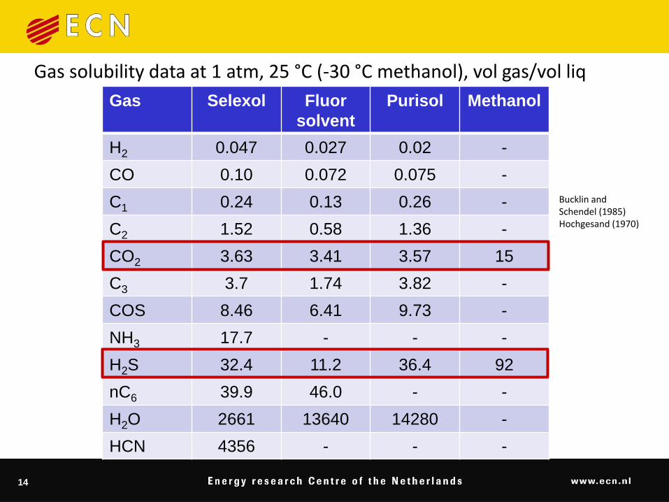
H2 0.047 0.027 0.02 -
CO 0.10 0.072 0.075 -
C1 0.24 0.13 0.26 -
C2 1.52 0.58 1.36 -
CO2 3.63 3.41 3.57 15
C3 3.7 1.74 3.82 -
COS 8.46 6.41 9.73 -
NH3 17.7 - - -
H2S 32.4 11.2 36.4 92
nC6 39.9 46.0 - -
H2O 2661 13640 14280 -
HCN 4356 - - -
Gas solubility data at 1 atm, 25 °C (-30 °C methanol), vol gas/vol liq
Bucklin and Schendel (1985)Hochgesand (1970)
14
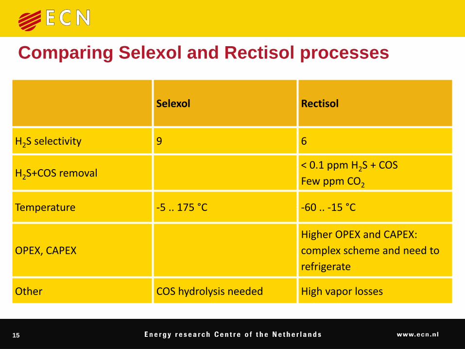
Selexol Rectisol
H2S selectivity 9 6
H2S+COS removal< 0.1 ppm H2S + COS
Few ppm CO2
Temperature -5 .. 175 °C -60 .. -15 °C
OPEX, CAPEX
Higher OPEX and CAPEX:
complex scheme and need to
refrigerate
Other COS hydrolysis needed High vapor losses
Comparing Selexol and Rectisol processes
15

Absorber/desorber column design
Absorption Stripping
16

Regeneration of solvents
Flashing Stripping Reboiling
17

18
Source: UOP

Selecting the absorption process in IGCC
Sulphur removal (notstringent) w/o CO2 removal
Chemical solvent
Physical solvent
Low Capex
Low steam requirements
Sulphur + CO2 removal2-stage Selexol
Other
Quoted as preferred
Depending on requirements
19

IGCC/CCS studies
NETL/Parsons 2002. Evaluation of Fossil Fuel Power Plants with CO2 Recovery. 2007. Cost and Performance Baseline for Fossil Energy Plants. DOE/NETL-2007/1281.
Foster Wheeler2003. Potential for improvement in gasification combined cycle power generation with CO2 capture. IEA report No. PH4/19, 2003. 2007. Co-production of hydrogen and electricity by coal gasification with CO2
capture. IEA Greenhouse Gas Program report 2007-13.
Politecnico di Milano / Alstom UK2011. European best practice guidelines for assessment of CO2 capture technologies.
20

New Developments
21
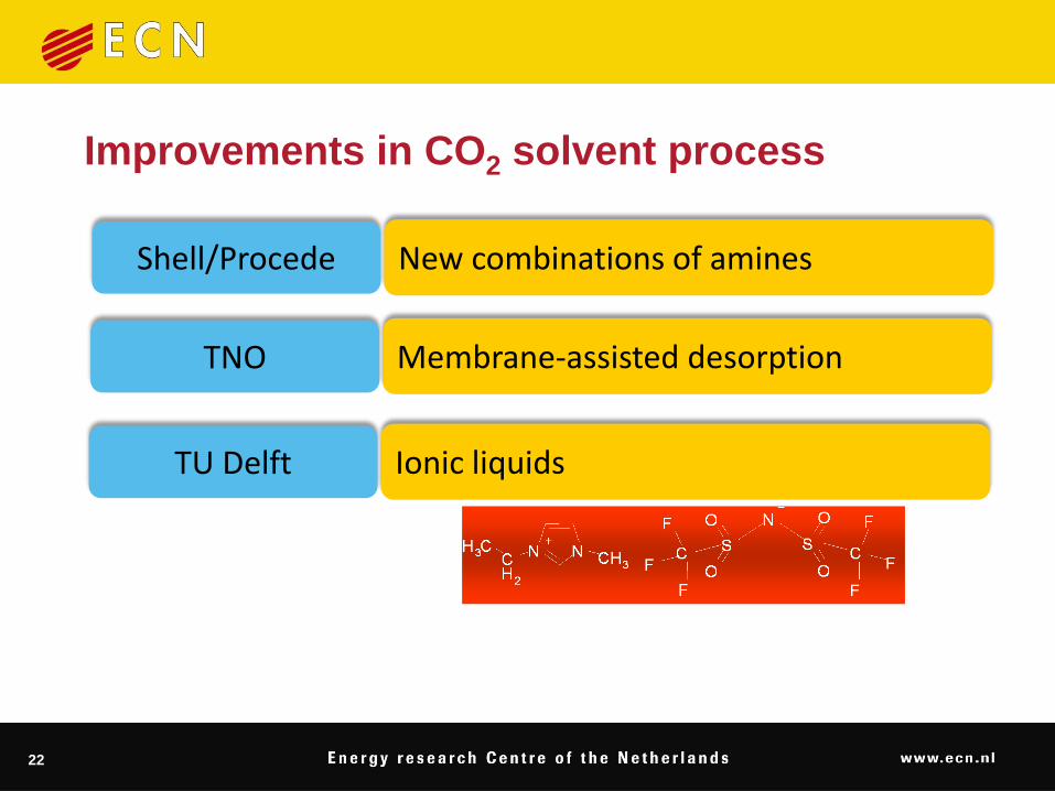
Improvements in CO2 solvent process
New combinations of aminesShell/Procede
Membrane-assisted desorptionTNO
Ionic liquidsTU Delft
22

Advanced Shift (Sweet/Sour)
Carbo et al (2009) Int J Greenhouse Gas Ctrl 3 (6) 712
23

Low-Steam Sour Shift
24

Sour H2 PSA
US2010.011955
25

Drivers for high-temperature gas clean-up
The higher process efficiency without syngas cooling and removal of water from the syngas: +5.2%-points*.
The elimination of sour water treating.
The elimination of the black mud produced in wet scrubbing of particulates from the syngas.
The potential related Capex and Opex savings.
The viability of air-blown gasifiers.
26
* Exergetic efficiency. Kunze et al. Energy 36 (2011) 1480

27
CO2 + H2CO + H2O ⇌
CO2
Syngas WGS 2%-6% CO
WGSH2 & CO2
Separation H2

28
SEWGS
→CO2 + H2CO + H2O
Syngas WGS2%-6% CO
CO2
H2
400 °C
25 bar

29
CO + H2O H2
CO2
CO2
CO2
CO2
CO2
CO2
sorbent sorbentcatalyst
CO2
Fe-Cr
Mg6Al2(OH)16CO3.4H2O
K-promoted Hydrotalcite (layered clay)
Meis et al. (2008)

Formation of MgCO3
3) Pressurisation
(dry CO2)
Re
lati
ve
inte
ns
ity
2 θ (degrees)
◊
◊
◊◊◊
◊
◊
◊
◊
◊
◊ ◊
◊
◊
◊
◊
◊
◊
◊
◊◊
◊◊◊
◊
◊◊ ◊
◊
2)Regeneration
Low pressure N2
4) Feed
CO2+steam (10 bar)
1) End of feed step
x
x
xx
x
x
x
x
x
x
x
xx
x
xx
x x
x x
x
0
10
20
30
40
50
0 200 400 600
Relative mass loss (%)
Temperature (°C)
0
2
4
6
8
10
12
0 50 100 150 200 250 300
cu
mu
lati
ve a
mo
un
t o
f C
O2
deso
rbed
(m
mo
l/g
)
cumulative amount of steam fed (mmol/g)
reference sorbent
new sorbent
30

31

32
CO2
product
rinse
repressurization
depressurization
FICFIC
H2
FICFIC
FICFIC
FICFIC
FICFIC
FICFIC
FICFIC
FICFIC
H2 product
PCVPCV
feed
purge
FIFI
FIFI
Steam
CO2
N2
CH4
CO
PCVPCV
purge
SEWGS multi-column unit at ECN

SEWGS process development unit at ECN
33

Alkasorb sorbent is stable
0
0.25
0.5
0.75
1
250 300 350 400 450 500
CO
2 in
to
p p
rod
uct
(%
dry
)
cycle no.
Van Selow et al (2010) GHGT-10, Amsterdam
34

Effect of feed pressure Wright et al (2010) GHGT-10, Amsterdam
35

36
0.0E+00
1.0E-09
2.0E-09
3.0E-09
4.0E-09
5.0E-09
6.0E-09
7.0E-09
8.0E-09
1340 1345 1350 1355 1360 1365 1370 1375 1380 1385 1390
Time [min]
MS
re
sp
on
se
[a
.u.]
1.0E-12
2.0E-12
3.0E-12
4.0E-12
5.0E-12
6.0E-12
7.0E-12
8.0E-12
9.0E-12
1.0E-11
Co-capture of H2S
H2S does not change CO2 sorption capacity or kinetics
K-AL
N2
H2O
CO2
0.0E+00 1.0E-12
H2S
Van Dijk et al (2011) Int J Greenhouse Gas Cntrl 5 (3) 505
400 °C
1.5 bar
11% CO2, 17% H2O, N2, (500 ppm H2S) 17% H2O, 83% Ar

37
Sufficient WGS activity before CO2 breakthrough
400 °C
30 bar
40 % H2O
17 % CO
17 % H2
20% CO2
200 ppm H2S
Van Dijk et al (2011) Int J Greenhouse Gas Cntrl 5 (3) 505

IGCC, ~400 MWeNo cap Selexol SEWGS
Net Efficiency % 47.7 36.5 38.4
CO2 avoidance % - 87.6 98.0
Specific energy use GJ/tonavoid - 3.7 2.6
Gazzani et al. GHGT-10
Performance comparison
38

Catch-Up Pilot Plant, Buggenum
Picture: Vattenfall
39

Catch-Up Pilot Plant, Buggenum
simultaneous optimization
of solvent and processes
molecular
mapping
solvent
parameters
solvent
candidates
process
specifications
and constraints
optimized
process
Damen et al. GHGT-10
40

Conclusions
Many Rectisol and Selexol units in operation
Physical solvents are attractive for pre-combustion CO2 capture in IGCC plants
Efficiency penalty for CO2 capture can be reduced
Improved solvents, membrane contactersReduction of steam demand for WGSHot gas clean-upProcess intensification (sorption-enhanced reactor)
41

Acknowledgements
42
caesar.ecn.nl