pre conference workshop - underground...
TRANSCRIPT

APPENDIX
PRE-CONFERENCE WORKSHOP
CONTROL OF GAS EMISSIONS AND OUTBURST IN COAL MINES

2002 Coal Operators’ Conference Tribute to Dr Ripu Daman Lama
204 6-8 February 2002 The AusIMM/Illawarra Branch
FOREWORD
Editor’s Comments I have attempted to accurately summarise the proceedings and in some cases to quote what speakers said. I apologise if I have misquoted anyone. The day proved to be very interesting and informative. I thank all participants for their frank and open discussion and contributions and especially Bruce Robertson for his untiring acceptance of my request to sum up and conduct the concluding session. The sharing of experience as seen today and at similar gatherings is what will keep the coal industry advancing and solving the technical problems which accompany deeper mining in hard times. John Hanes February, 2002 Phone: 02 4295 4255 Email: [email protected]

2002 Coal Operators’ Conference Tribute to Dr Ripu Daman Lama
The AusIMM Illawarra Branch 6-8 February 2002 205
PRE-CONFERENCE WORKSHOP
Control of Gas Emissions and Outburst in Coal Mines RESERVOIR ASSESSMENT
Gas Content Measurement ........................................................................................................ 207 R. Danell Permeability .............................................................................................................................. 213 R. Jeffrey Coal Microscopy in Gas Permeability Studies .......................................................................... 218 Lila Gurba Gas Composition ....................................................................................................................... 227 A. Filipowski
OUTBURST ASSESSMENT
Understanding the Mechanisms of Outbursts Using a Mechanistic Approach ......................... 232 X. Choi Thresholds and Compliance Issues ........................................................................................... 234 C. Harvey
GAS EMISSION MODELLING
Coal Mine Development Gas Emission Modelling ................................................................... 238 M. Slater and E. Yurakov Longwall Goaf Gas Flow Mechanics ........................................................................................ 244 R. Balusu
DRILLING TECHNOLOGY - WHERE NEXT?
Surface to Inseam ...................................................................................................................... 249 F. Bos In-seam ...................................................................................................................................... 258 J. Hanes Surveying .................................................................................................................................. 260 H. Verhoef Tower Colliery Drilling Difficulties .......................................................................................... 273 M. Brown & P. Eade
GAS DRAINAGE AND EXTRACTION Maintenance .............................................................................................................................. 276 B. Newman
CONCLUSIONS
Summation and Conclusions ..................................................................................................... 280 B. Robertson
APPENDIX A Suggested Outburst Report Form ......................................................................................................... 285

RESERVOIR ASSESSMENT

2002 Coal Operators’ Conference Tribute to Dr Ripu Daman Lama
The AusIMM Illawarra Branch 6-8 February 2002 207
GAS CONTENT MEASUREMENT
Richard Danell1
See following pages for Power Point Presentation Discussion and Questions Bob Newman, Tahmoor – Can we assume that one lab consistently reports a higher gas content than the other labs? Richard – There is random variability. On a statistical analysis, some labs report higher gas contents than others. For risk assessments for outbursts, we will make the results known to industry and will involve the wider industry. Shane Coleman, New Wallsend – Is there a real difference in gas contents determined by the direct slow desorption and the quick crush methods, and if so, is it consistent? Richard – There is no systematic difference. Quick crush was introduced to improve turn around times. There is a lot of discussion about whether there is more variability seen with the slow desorption technique and there is some question as to when the measurement is finished. We have not conducted a study to compare the two methods. Ray Williams, GeoGas – We have done many comparisons of the two methods since 1997. The differences are not real but there is some scatter. Alan Cook, Keiraville Konsultants – Re coal oxidation, how are the samples taken for the oxidation studies? Are they from a purged coal face? I suspect not which causes worry. There is much literature which says you should purge the coal face and I suspect CSIRO is not following the recommended methods. Richard – This is part of a separate CSIRO study. The samples were collected after core was processed in the normal manner for quick crush and also through an evacuated mill. There were no differences in the results, so we did not take it further.
1 BHP Billiton


2002 Coal Operators’ Conference Tribute to Dr Ripu Daman Lama
The AusIMM Illawarra Branch 6-8 February 2002 213
PERMEABILITY
Rob Jeffrey 1 See following pages for Power Point Presentation
DISCUSSION AND QUESTIONS Alan Cook – You did not mention the difference between fracture permeability and bulk permeability. Rob – For field conditions, the volume of the test sees a huge number of fractures. The presence of fractures is important in core samples as a fractured core will yield totally different results from an unfractured core. In reality, it is difficult to take a core sample from fractured coal. Core testing tends to under-represent the permeability. Fracture permeability is very important in reservoir analysis. The effective permeability in a fracture has a tremendous effect on the overall permeability as a very small opening of a fracture increases the permeability significantly. The permeability of a fracture increases as w2/12 where w=the width of the fracture. The fracture is the dominant flow path. Anon. – If the reservoir is stimulated by hydraulic fracturing, then the permeability is measured, higher permeability is recorded because of the induced fracture. Sometimes, injection falloff in coal can be deceiving. Rob – Seeing past the skin or damaged zone around a well can be a problem for short term tests. Short term tests are not as reliable as longer term tests as they do not see as far into the coal seam. David Casey’s group are doing longer tests with 4 to 6 hours of injection and 12 hours of falloff. The longer tests yield better information. Bruce Robertson, Anglo Coal – Re application of permeability tests to underground drainage, directional permability is a fracture-driven issue which cannot be resolved with single hole tests, but can be resolved with a well defined interference test. The direction of maximum permeability is critical to designing effective underground drainage. Rob – There have been a number of interference tests done around Australia now, but I wish there were more as people tend to use them as a benchmark to get an idea of what the directional permeability might be, the ratio between maximum and minimum. Until we get these tests done, we suffer from a lack of data to use in the models.
1 CSIRO

2002 Coal Operators’ Conference Tribute to Dr Ripu Daman Lama
218 6-8 February 2002 The AusIMM/Illawarra Branch
COAL MICROSCOPY IN GAS PERMEABILITY STUDIES
Lila Gurba1 See following pages for Power Point Presentation Discussion and Questions Patrick Humphreys, Newlands – What is the turnaround time for tests? Colin – Lila will have to answer this. Ray Williams – Are there any macro markers? Colin – I am not sure. Lila might provide more information. David Titheridge, Tahmoor – I have recently rechecked some areas at Tahmoor in light of Lila’s work. I am beginning to see some differences in the coal. In some areas I can see some 1 mm wide mylonite zones. I have also checked the distribution of carbonate veins. I can see differences but it difficult to to quantify them and is very subjective. I now need to re3view the microscopic studies. At Tahmoor, about 30 cm below the roof, there is a stockwork of shallow dipping carbonate veins. They are best seen in a vitrinite rich layer. This is underlain by a sideritic mudstone. Where there is siderite below the mudstone, the carbonate infill is above the mudstone. The stockwork is generally not seen in the bottom part of the seam.
1 Colin Ward, University of NSW presenting for Lila Gurba

2002 Coal Operators’ Conference Tribute to Dr Ripu Daman Lama
The AusIMM Illawarra Branch 6-8 February 2002 227
THE ROLE OF NITROGEN IN GAS CONTENT ASSESSMENT
Andrew Filipowski1 See following pages for Power Point Presentation When gas contents are measured in the BHP Billiton gas laboratory, gas composition is also analysed. These two parameters determine where a sample lies with respect to the threshold. We have found that if N2 is greater than 20%, the gas content will be below the outburst threshold. We hypothesise that Nitrogen can be used as a faster assessment of outburst potential than gas content. The gas composition of a coal sample changes with time. The proportion of each component relative to other components is transient. This is due to the different rates of desorption of the different component gases. Some gases desorb very quickly, eg the higher hydrocarbons and CO2. CH4 is slower and N2 is the slowest of the coal seam gases. The higher hydrocarbons are generally present in small amounts, but, as they desorb very quickly, often before the coal sample is sealed into its canister, they are often missed on gas analysis. Nitrogen remains in the coal for a long time. CO2 has a great affinity to coal, but N2 is very faithful to coal and desorbs slowly. In virgin coal, there is typically 1.5% N2. Bulli seam coal of 15 m3/tonne gas content has around 0.2 m3/tonne N2. During the desorption process, most quickly desorbing gases are depleted quickly and the proportions start to change. N2 desorbs very slowly and its volume in the coal remains fairly constant. To visualize the process, imagine a rock island (N2) in the ocean. At high tide (virgin conditions) the rock is almost covered and there is little to be seen. As the tide recedes (desorption proceeds) the rock (N2) starts to be more obvious. One problem associated with N2 is the N2 produced by oxidation. When a coal sample is collected under ground, the coal is exposed to air and oxygen is available for oxidation. Oxidation produces proportionally excess N2 in the gas mixture, ie from air and desorbed from the coal. During the first few days of a desorption test, the majority of N2 in the sample container is is excess N2 from air. Later, as consecutive samples are taken of the gas, the N2 from air is gradually depleted and there is more N2 desorbed from the coal. The two types of N2 can only be differentiated by isotopic analysis. A more reliable source for a gas analysis would be through direct sampling of a drainage hole. There is no oxidation of the coal sample. When gas composition is quoted, the stage of gas desorption of the coal sample should also be quoted. In the Illawarra, the coal seams close to the escarpment have been considerably drained of gas. Further to the west, the gas composition of the coal is close to its original composition, ie 1.5% N2, 97% CH4 and minor CO2. Tahmoor at 90+% CO2 is an exception as is Metropolitan with its variable CH4/CO2 composition. During drainage, as the CH4 and CO2 desorb, the N2 volume remains fairly stable and its proportion in the total gas mixture increases. High gas content, low N2 proportion: low gas content, high N2 proportion. Where the gas content is very low, N2 can constitute up to 50% of the gas. If N2 is high, the content will be low and outbursts will not be possible. With gas desorption studies of exploration cores, slow desorption tests can take up to a couple of months. With these, the CH4 desorbed decreases over time while the N2 increases. The graph shows how the gas content of a coal sample can be estimated from the N2 content of the desorbed gas. Where there is a large spread of N2 data for a gas content on the graph, this is due to sample oxidation. When a gas sample is collected from a desorbing coal sample, the N2 comes from the air in the container plus from the coal. A bag sample of the gas from an underground drainage hole would give a more reliable test and
1 Coal Geotechnical Services

2002 Coal Operators’ Conference Tribute to Dr Ripu Daman Lama
228 6-8 February 2002 The AusIMM/Illawarra Branch
less scatter of data. If you have a gas composition, you can assess the degree of coal degasification. This is a much more economical method of gas content assessment than desorption testing. It will not replace all content testing, but offers a quicker and less expensive method for infill testing in the mine. It also provides a good reason for not injecting N2 into drainage holes. Discussion and Questions Ray Williams, GeoGas – GeoGas has a 180 degree difference in the interpretation. With lower content coal samples, there is more N2 and CO in the gas mix. We therefore feel most of the N2 is artificial. Other coals, especially some Queensland coals do not show the same relationships with N2. We need to sample some gas drainage boreholes. Andrew – Samples should be taken from Q2 and Q3. With the Q3 sample, we typically get deficient O2 and CO2 and raised CO. We tested some drainage holes and an exploration bore hole. On the graph, we show the results. On day 1 there was 5% N2. Over the next 15 days the N2 dropped when we expected it to rise. This most probably happens because the oxidation process is most intensive in the initial stages, when there is plenty of oxygen in the enclosed bomb air. Thus when the bomb is opened in the lab some time later and the first gas sample is taken for analysis, the nitrogen content in the sample is relatively high (say 5%). This is mainly the air nitrogen. In consecutive samples, with the depletion of air in the bomb, while the gas desorption from coal is still high, the nitrogen content in gas samples drops (to around 1%). Later samples indicate continuous increase in nitrogen content (up to around 50 - 60%), and this is believed to be mainly a coal nitrogen. There are still questions to be answered, but we have a good working hypothesis which holds promise for faster and less expensive assessment of outburst potential.

OUTBURST ASSESSMENT

2002 Coal Operators’ Conference Tribute to Dr Ripu Daman Lama
232 6-8 February 2002 The AusIMM/Illawarra Branch
UNDERSTANDING THE MECHANISMS OF OUTBURSTS USING A MECHANISTIC APPROACH
Xavier Choi1 First of all, I would like to acknowledge my colleague Mr Mike Wold. Mike and I have been working together in the last few years on a number of projects related to gas in coal, and on a couple of projects on outbursts which were funded by ACARP with support from BHP and Shell Coal. The aim of my talk is to try to get a better understanding of the mechanisms of outbursts using a simple mechanistic approach. I think most of you know what an outburst is and some of you might know very well about the outburst that occurred in Tahmoor. However, in an outburst that occurred in the Ukraine, about 14,500 tonnes of coal were ejected and about 600,000 m3 of gas was released. One of our main interest is to understand why does an outburst occur. Let us do a simple experiment. We have two balloons, one filled up with water and the other filled with gas. Since the balloons are stretched to a similar extent, we would expect that the pressure in the gas and the water in the balloons to be very similar. If we increase the pressure, it will cause the balloons to expand and the tension in the membranes of the balloons will also increase. If I squeeze the balloons, both the pressure and the tension in the membranes will change. Perhaps it is a simple way to understand the meaning of poroelastic effect. As coal is a fractured porous medium either fully or partially saturated with water, we would expect a change in stress or pore pressure as a result of mining or gas drainage would induce similar responses in coal. We notice that the balloons do not burst under the current condition (or state) because the membranes are strong enough. In order to cause the balloons to burst, we need something that would provide the triggering mechanism to enable the system to overcome the energy barrier. In this case, the barrier is provided by the strength of the membrane. However, the balloons will burst if we squeeze them hard enough or if we increase the pressure high enough. When the balloons burst, rupture of the balloon will most likely be initiated at the weakest spot in the membrane. Of course I can create a weak spot by poking the balloon with a needle. We may notice that the bursting of the balloon filled with air is much more violent compared to the balloon filled with water because of the fact air is more compressible than water, and can store more energy under the same pressure. Failure at the weak spot removes the energy barrier and allows the gas to expand, causing further failure of the membrane until the system reaches a new equilibrium (or stable) state. However, during an outburst, it may go through a few meta-stable states before reaching the final equilibrium state. We can also see, from this simple experiment, the interaction between stress, strength and gas. In coal, a similar triggering mechanism for outbursts can be provided by geological structures, sheared coal, fractures or other features that provide the “weak spots”. As coal is a soft rock, the amount of strain energy as a result of elastic deformation can be quite limited. In order for coal to fail in a violent manner such as outbursts (or similar to a rock burst in hard rocks where a large amount of energy can be provided by strain energy during failure because of the stiffness of the rock), other form of energy need to be available, and that is where the compressed gas comes into the picture. We know that coal will yield (or fail) if the stress in the coal gets high enough. If we keep applying stress to the coal after initial failure, due to destruction of the fabric of the coal, the coal will become weaker and softer. Therefore, during mining or roadway development, as the size of the mine opening increases, because of increase in stress concentration, we would expect the volume of yielded coal to increase with lose of some of its initial strength and stiffness. During an outburst, not only that the coal need to have failed such that the energy barrier is removed or overcome, but there must also be compressed gas to provide the energy to drive the outburst. But, where does the gas come from?
1 CSIRO

2002 Coal Operators’ Conference Tribute to Dr Ripu Daman Lama
The AusIMM Illawarra Branch 6-8 February 2002 233
We know that most of the gas in coal exists in the adsorbed state on the surface of the coal in the micropores, and we normally express the amount of gas adsorbed in terms of gas content. Based on laboratory observations, it is generally believed that weak (van der Waals) force exists between the gas molecules in the free and adsorbed states, adsorption or desorption can occur almost instantaneously to reach new thermodynamic equilibrium as a result of changes in partial pressure. We have developed and used a coupled geomechanical-reservoir model to model outbursts. Under certain conditions, the model predicted that outburst will occur when we have reached a certain stage of mining. In some recent studies, we have tried to find out what are the effects of gas composition (percentage of CO2 and methane) on outbursts. We have conducted some runs to study the effects of different desorption rates using the conventional assumption that the rate of desorption is governed by Fickian diffusion, that is, rate of diffusion for a given coal is mainly controlled by particle size and gas concentration gradient. It was observed that, even by changing the desorption time constant from a few days to the order of minutes, less than 10% difference in pressure and pressure gradient around the face was observed. As this may not be able to account for the difference in CO2 and methane outbursts observed in the field, a different mechanism is proposed. To understand this, we may have to look at what happens during mining. Through borehole or face drainage, the region near the face will become partially saturated with water after gas has started to desorb. But because of surface tension (or capillary) effect, if we look at the relative permeability curves for gas and water in coal, we can see that only a small portion of water can be drained. For the case shown here, it is about 10% because the effective permeability (or relative permeability factor) to water is zero at about 90% water saturation. Considering that the porosity of coal is about 2%, the volume of free gas in the cleats and larger voids (secondary porosity system) would at most be about 0.2%, and a higher desorption rate will not have any effect in increasing the maximum amount of free gas. However, as observed in the model studies and mentioned earlier, desorption rate does have some effect on the pressure and pressure gradient around the face. To understand the difference between CO2 and methane outbursts, it may be important to find out what happens after an outburst has been initiated and the coal has started to break up into smaller fragments. We can see from the model that the coal deforms at a high strain rate after outburst initiation. As the coal continues to expand and disintegrate into smaller fragments, new surfaces will be formed. Pressure around the new surfaces and in the voids, which are close and connected to the new surface, will drop very quickly. As mentioned earlier, gas is physically adsorbed on the coal surface, and the adsorbed gas can be released quickly when partial pressure is reduced. Based on this, it may perhaps be important to look at the shape of the sorption isotherms for CO2 and methane and the rate of change in gas content with respect to change in partial pressure. We can see that, for the range of pressures generally encountered, the slope for CO2 is at least a few times greater than that for methane. This may perhaps explain why CO2 outbursts are generally more violent compared to methane outbursts. To summarise, we know that the initiation of outbursts can be controlled by a number of factors. We may be able to understand each individual process or factor to some depth, but to understand how they interact, especially under reasonably complex conditions encountered in some mines, can be very difficult, and that is one of the reasons why we may need to use numerical modelling. Also, to understand outbursts, we may need to treat rock/coal/gas as a system, and to understand, as a result of mining, how changes in boundary and field conditions can affect the behaviour of such a system. It should be noted that the boundary of the system is continually changing as mining progresses. We are currently trying to understand the mechanisms of outbursts better by using a new model that we have developed recently. We would like to model each process as closely as we can as our understanding of the main processes and factors improves. By using of a single parameter such as gas content and ignoring all the other factors for outburst prediction will likely produce a fair bit of scatter as we can observe from the data collected by Ripu. However, we know that if we can remove enough gas so that there is not enough energy to drive an outburst even in the weakest coal, we should be quite safe (however, it does not mean quasi-static type failure due to yielding of coal will not occur). However, we may have problem in maintaining production when mining through coal with high gas content and low permeability. Perhaps, after we have gained enough understanding of the mechanisms, we may be able to devise other ways of mining through structures and low permeability coal in addition to gas drainage. We may perhaps be able to mine in such a way that we can allow the coal to fail in a predictable and controlled manner, and perhaps even making use of the energy stored in the gas in breaking up the coal in a beneficial way.

2002 Coal Operators’ Conference Tribute to Dr Ripu Daman Lama
234 6-8 February 2002 The AusIMM/Illawarra Branch
THRESHOLDS AND COMPLIANCE ISSUES
Chris Harvey 1
The ideas presented today will be the ideas of the author and not necessarily those of the Department of Mineral Resources. The prime role of the rules and regulations is to protect people. An outburst is the violent ejection of coal and gas. Also required are a steep pressure gradient, high quantity of gas, high rock pressure and low coal. Lower permeability also plays a role but it is partly determined by the other factors. See Figure 1. Lama in 1991 and also in the International Symposium on Outbursts, 1995, referred to desorbable gas content, sheared coal and non-sheared coal and suggested threshold values for safe mining. Based on Lama’s work, threshold values were imposed under a Section 63 notice of the Coal Mines Regulation Act. They were imposed on each mine by the District Inspector for that mine, not by the Chief Inspector. This purposefully left an avenue for review by the Chief Inspector under section 65 and provided a potential to alter gas thresholds. This eventually lead to some mines having different threshold values from other mines. Today, we use total gas content whereas Ripu’s suggestions were based on desorbable gas. The focus is on mining or no mining based on gas content. The reason Ripu focused on gas was that it could be measured reasonably easily with a standard test. The quick crush method gives a fairly quick turnaround of information compared with the older desorption technique. It is important to identify the potential for a risk such as outbursts to be identified before anything can be done to manage the risk. Gas threshold values are used in conjunction with outburst management plans. The OBMP’s provide a structured approach with key elements to manage the outburst risk. The Department, in order to gain some standardization or consistency in OBMP’s developed OBMP guidelines. Figure 2 summarises the procedures. Outburst prediction identifies the key factors which give rise to an outburst. The main component of outburst prevention that has been identified for and successfully applied in the Bulli seam is gas drainage. The two key components of the OBMP system (Figure 2) are “audit” and “corrective action and review”. Without these, there is no guarantee that the permit to mine is adequate and will lead to safe mining. The audit approach is the most important fundamental because it determines that you do what you plan to do. Figure 3 shows the result of applying this approach to the Bulli seam. A large number of outbursts occurred each year up to 1994 then the District Inspectors imposed the section 63 notices in May 1994. Since then there have been 7 relatively minor outbursts. Although this is a good outcome, it also represents a problem: ie the outburst problem appears to have been solved. Outburst risk in the Bulli seam is deemed to be successfully managed through adherence to the threshold values. But the gas thresholds only relate to one aspect of outburst risk, gas content. Gas content thresholds, like any other standard, need to be analysed and reviewed on a regular basis. An understanding of the warning signs at the face is the fundamental final barrier. Discussion and Questions Jason Moultrie, North Goonyella – How do you distinguish between minor and major outbursts? Chris – Mainly on size. Generally the outbursts were less than 100 tonnes. The biggest Bulli seam outburst was 400 tonnes. The minor outbursts have usually been only a shuttle car load and people were not injured or endangered. The two outbursts which occurred on the West Cliff longwall face from undrained coal. There was no structure identified and the burst was driven by CO2. In hindsight, if anyone had been on the tailgate side of the bursts, there would have been a fatality caused by asphyxiation. There was in excess of 12% CO2 in the air. It was regarded as minor as there was little coal dislodged. Chris Hudson, Moranbah North - With regards to mylonite identified under the microscope, how sensitive is it in a high stress environment for causing outbursts and can it be identified underground?
1 NSW DMR
2002 Coal Operators’ Conference Tribute to Dr Ripu Daman Lama
The AusIMM Illawarra Branch 6-8 February 2002 235
Chris – Virtually all Bulli seam outbursts have had some degree of mylonite apparent. Mylonite has been used as an indicator of potential Bulli seam outbursts. From what I understand from Collin’s presentation today, the microscopic mylonite is effectively neutralized by the cement. It therefore does not contribute to free drainage. Chris Hudson – Is there a relationship between effective stress and mylonite? Chris – Most of the Bulli seam outbursts have occurred on compressive structures such as strike-slip faults which have associated mylonite. But mylonite has also been mined without an outburst where the gas has effectively drained from the coal. Ripu identified a correlation between gas content and high and low stress regimes. I feel that as your stress regime changes, there is a need to vary the gas contents which are safe for mining. By focusing on gas only, there is a risk of missing the total picture and putting people at risk. (comment by J. Hanes during editing – The integrity of the coal plays a role in outburst initiation and propagation. The mylonite or sheared coal of the Bulli seam varies from a centimetre thickness to over a metre. Its role in an outburst is uncertain other than it has no strength and has a huge surface area for sorption of gas. It probably also has a fast desorption rate. At Leichhardt Colliery in Central Queensland, the majority of outbursts had no visible mylonite associated with them. However, the coal was heavily cleated which reduced the strength of the coal mass. The outbursts ejected the coal as a buckle failure with the cone axis perpendicular to the cleats. The major fatal outburst of 500 tonnes was from partly sheared coal, however a large amount of coal with thick sheared coal had been mined safely without outburst. At Dartbrook and Tahmoor where the coal is strong, I feel that mining could be safely conducted at higher gas contents than the current thresholds. However, if a sheared coal zone were intersected at a high gas content, an outburst could occur.) Brian Lyne, Queensland Mines Department – Have there been any reviews of international outburst literature and where does the Bulli seam fit? Is there an international standard or is outburst management country specific, mine specific or even culturally specific? Chris – Since Ripu died in 1997, the industry has lost its main conduit with international research into outbursts and gas. In his 1991 report, Ripu did place the Bulli seam in context with overseas outburst mines with regards to gas contents. This has not been progressed since 1991. A number of us who are involved with outburst studies are concerned that the collective knowledge of the industry could be lost unless something is done to promote further research and document the knowledge. Without ongoing research and documentation, future generations of miners will have a steep learning curve. John Hanes has submitted a proposal to ACARP to promote a group to recommend and direct outburst research and dissemination of information. Phillip Eade, BHP Billiton – Outbursts are seen to be under control, ie there is a fair factor of safety in gas content threshold values. In the factor of safety there is a cost component to productivity and safety. I cannot see how we can clearly account for stress or the other 14 or so parameters suggested by European workers. We need to continue research towards a fundamental understanding of outbursts. Until we have this understanding, it is difficult to go much further on a lot of the outburst parameters and put them into a threshold. The reason for outburst management success in the Bulli seam is the healthy safety factor with gas content. Wayne Green, Helensburgh Coal – After the South Bulli fatality, the industry embraced the suggested outburst management procedures and made people aware of what had to be done, but as the years have passed, a degree of complacency has set in. A lot of people believe the drainage programmes are the most effective means of achieving the end but the other controls have disappeared. They tend to ignore some of the warning signs. There is a need to make miners aware that drainage is not a panacea and that other factors such as warning signs at the face should be re-emphasised in training. Bruce Robertson, Anglo Coal – Regarding where we should go with research, most of the body of knowledge about outbursts comes from the Bulli seam. Now Queensland mines are getting closer to outburst conditions and there have recently been a couple of small outbursts in Queensland mines. That is sufficient justification for gaining information from other areas. We should not just be using data from outbursts, we should also be collecting and using the large amount of data which comes from the mines which are not having outbursts. There are lots of combinations of the parameters talked about which have resulted in a successful non-outburst mining outcome. We can learn a lot from that without having to wait for the next big outburst if we are proactive. This requires industry effort to collate their data in a scientific and systematic way that means something in a regional context. With regards to international experience, there is a lot of data and information in the two volumes produced by Ripu Lama, but I suspect it is only a small proportion of the total experience. A problem with translating international papers is they sometimes miss the point. There is enough information in Australia for us to make our own way for the time being. Alan Cook – The Bulli seam is unusual. When mining moves into other seams settings, the Bulli seam experience might not be a good guide. Quantification of structural features is very difficult .

2002 Coal Operators’ Conference Tribute to Dr Ripu Daman Lama
236 6-8 February 2002 The AusIMM/Illawarra Branch
Ray Williams, GeoGas – Rick Davis and Ripu in the early 90’s put out a document seeking consensus that if the gas content was reduced significantly, outbursts would be prevented. This underpinned the KCC outburst management plans and those of other companies that followed Ripu’s lead. The research being conducted now in outburst modeling is good, but as far as the Bulli seam mines are concerned, it is hard to see anything replacing gas content thresholds in outburst management. However, Queensland is different. The Queensland mines mine down dip, so mining conditions change rapidly. We take these changes into account and consider the effects of desorption rate as one condition. With regards to stress, I feel that the gas content threshold could fail when working with high stress. Mt Davy in New Zealand and Ellalong Colliery in NSW both had outbursts when their gas content levels were just above the Bulli seam thresholds. But both mines had high stress conditions. Another issue which needs to be considered with mathematical modeling is the width of safety barriers between the face and any structure. In the Bulli seam, the accepted barrier width based on Ripu’s work is 5 m. But how well does this barrier width apply to Hunter Valley or Queensland conditions where the seam is thicker and other parameters differ? I think this is an area of fundamental research that could produce useful results. With respect to initiating outbursts, until someone invents a gadget that does not rely on gas content and which can be connected to the face to predict an outburst, I think we have to rely on gas content. Developing an alternative has not proven very practical. Our development rates are very high compared with European mines which use other techniques for assessing outburst proneness. Chris – The gas pressure gradient has also been shown to be important. Whenever we take a core for desorption, should we also be taking a gas pressure measurement? When Ripu proposed his thresholds, he did postulate a gas pressure for each threshold value. So do we also try to measure pressure each time we sample content? Do we also try to measure the strength of the coal? Then by research, do we plug these factors into a mechanism to give a combined outburst risk indicator instead of just relying on gas content? Rob Jeffrey – The gas content should relate to the gas pressure unless you are way off the isotherm. If you are mining at a rate that the isotherm is tracking the pressure, then measuring the content tells you the pressure. Bruce Robertson – The pressure gradient near the face is critical, but it is not easy to measure quickly. Whatever is measured, it needs to be reliable. The holy grail of research would be to define precursors and warnings. We have tried microseismic, we have sniffed for strange gases, we currently look at observable features such as changes in micro and macro structures such as cleat and coal behaviour. We need to keep the door open to this type of research as if we could come up with a reliable precursor system, this would give us another barrier. All the other things we have talked about just do not seem practical.

GAS EMISSION MODELLING
2002 Coal Operators’ Conference Tribute to Dr Ripu Daman Lama
238 6-8 February 2002 The AusIMM/Illawarra Branch
COAL MINE DEVELOPMENT GAS EMISSION MODELLING
Miles Slater and Eugene Yurakov 1 Abstract The main aims of this paper are to describe:
The main gas reservoir parameters used in gas reservoir modelling, Application of a reservoir simulator, SIMED II, to understand how such numerical simulations
facilitate gas emission evaluation and control during gate road development, and The incorporation of mine planning and scheduling inputs, along with gas reservoir models into
interactive models of gateroad development emissions.
The development emission response (over time) to initial gas reservoir parameters is determined using the SIMED II gas reservoir simulator. An interactive EXCEL spreadsheet development model uses these rib emission decline curves, mining and ventilation parameters and a range of operational variables to provide a mine planning tool for assessment of likely gateroad gas emissions. Introduction The sensitivity of underground mining to gas emission is rising with :-
Planned production rates up to 6 million tonnes per annum, Increasing gateroad lengths (more than 4 km), Wider longwall faces (up to 350 m), Thick seam mining, and Deeper coal seams with higher gas content coals.
The requirement to define likely mine gas emission during gateroad development is increasingly important. The load on mine ventilation correspondingly increases with finite limits on :-
Practical main fan duty, Gas dilution capacity, Sustainable intake/return pressure differentials, and For long gateroads, the supply of sufficient air to the face circuit.
The excess of likely gas emissions over available ventilation dilution capacity must be controlled through gas drainage or gas capture techniques. Application to Coal Mine Gas Emission Assessment Development emission modelling combines gas reservoir properties with mining parameters to facilitate mine planning (Figure 1). The model is based on roadway gas emission decay curves, derived from the gas reservoir simulator SIMED II.
1 GeoGAS Systems Pty. Ltd.

2002 Coal Operators’ Conference Tribute to Dr Ripu Daman Lama
The AusIMM Illawarra Branch 6-8 February 2002 239
Well testing - pore pressure, permeability,
l i h i
Gas content, composition, desorption rate testing
Gas sorption capacity
Relative permeability determination
Seam thickness, density
Gas reservoir sizeDevelopment Gas Emission
Modelling(SIMED II &
EXCEL based)
Longwall Gas Emission Modelling
(Pore Pressure Model)
FLAC pore pressure modelling
Stratigraphic data
Mine plan, schedule, milestone
identification
Ventilation modelling
Gas drainage requirments
Ventilation modelling &
design
Gas drainage modelling & engineering
design
Mine plan, schedule, milestone
identification
Ventilation modelling
Geology and Gas Reservoir Properties
Temperature
NoYes
Fig. 1 Modelling Algorithm with Basic Input Geology and Gas Reservoir Parameters

2002 Coal Operators’ Conference Tribute to Dr Ripu Daman Lama
240 6-8 February 2002 The AusIMM/Illawarra Branch
SIMED II MODELLING SIMED II is an implicit finite-difference code, developed to describe the flow of gas and water in coal seams. SIMED II is a two phase (gas and water), three-dimensional, multi-component gas, single or dual-porosity reservoir simulator designed to model mixtures of adsorbed gases flow. In this application it is used to model the mine roadway emission. Additionally, the production behaviour of surface wells and in-seam can be history matched or predicted. The main gas reservoir modelling inputs in approximate order of importance are:-
HIGHEST IMPORTANCE Gas content and composition Permeability Seam thickness Gas sorption capacity Desorption rate Relative permeability Porosity Coal compressibility Pore pressure
LOWEST IMPORTANCE
Relevant features of the SIMED II gas reservoir simulator are:
Simulation of the behaviour of coal seam gas reservoirs as dual-porosity1, Multi-component gas mixture simulation as combination of gases and water (multi-phase) within the coal
seam, Provision for multiple coal types within the one simulation, defined by permeability, porosity and
desorption isotherm parameters. This is particularly important for dipping seams, where grid elements surrounding, and along, a roadway need to be assigned varying gas content, permeability and pore pressure, and
Modelling the effect of rib emissions in underground coalmines using a grid block face drainage option. This simulates the gas drainage to atmospheric pressure from a grid block element. If necessary the rib emission can be modified in real-time during the simulation, to mimic continuing mine development.
EXCEL SPREADSHEET MODEL
The main output from SIMED II modelling is a rib emission time-decay profile of a defined, static rib. An interactive EXCEL spreadsheet is then used to enable calculation of development gas emission in response to the following mining parameters:
Panel development rate, Panel length, Air quantity at the last cut through (intake entry air is calculated), Air leakage, a function of roadway and stopping resistance factors and pillar dimensions, Number and arrangement of headings (intakes / returns), Pillar dimensions, Gas emission in terms of CH4, CO2 or “seam gas”, and Options in permeability, gas content or other basic parameters.
A common scenario might be gate road development down dip, with varying gas content, seam thickness, permeability, pore pressure and gas desorption rate. To facilitate SIMED II modelling it is usual to graph the main mining parameters and assign representative “regions”. For the case in Figure 2, three regions have been defined.
1 Dual porosity accounts for the micro-permeability of the coal matrix, along with the macro-permeability of the cleat systems. The desorption time constant restricts the rate at which gas can move from the coal matrix to cleat and fracture system (where pressure gradient controls the flow).
2002 Coal Operators’ Conference Tribute to Dr Ripu Daman Lama
The AusIMM Illawarra Branch 6-8 February 2002 241
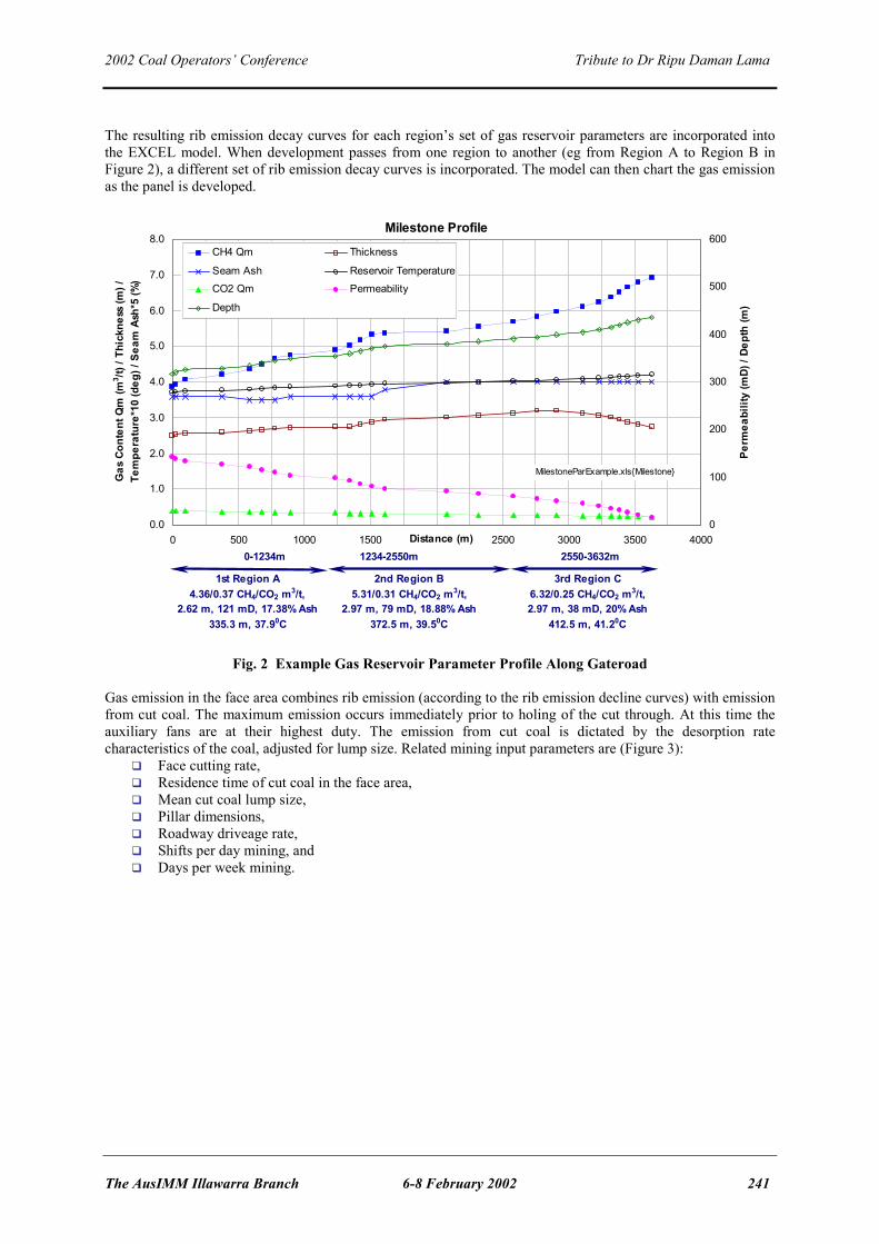
The resulting rib emission decay curves for each region’s set of gas reservoir parameters are incorporated into the EXCEL model. When development passes from one region to another (eg from Region A to Region B in Figure 2), a different set of rib emission decay curves is incorporated. The model can then chart the gas emission as the panel is developed.
Milestone Profile
0.0
1.0
2.0
3.0
4.0
5.0
6.0
7.0
8.0
0 500 1000 1500 2000 2500 3000 3500 4000Distance (m)
Gas
Con
tent
Qm
(m3 /t)
/ Th
ickn
ess
(m) /
Te
mpe
ratu
re*1
0 (d
eg) /
Sea
m A
sh*5
(%)
0
100
200
300
400
500
600
Perm
eabi
lity
(mD)
/ De
pth
(m)
CH4 Qm Thickness
Seam Ash Reservoir Temperature
CO2 Qm Permeability
Depth
0-1234m 1234-2550m
1st Region A4.36/0.37 CH4/CO2 m3/t,
2.62 m, 121 mD, 17.38% Ash335.3 m, 37.90C
2nd Region B5.31/0.31 CH4/CO2 m3/t,
2.97 m, 79 mD, 18.88% Ash372.5 m, 39.50C
2550-3632m
3rd Region C6.32/0.25 CH4/CO2 m3/t, 2.97 m, 38 mD, 20% Ash
412.5 m, 41.20C
MilestoneParExample.xls{Milestone}
Fig. 2 Example Gas Reservoir Parameter Profile Along Gateroad
Gas emission in the face area combines rib emission (according to the rib emission decline curves) with emission from cut coal. The maximum emission occurs immediately prior to holing of the cut through. At this time the auxiliary fans are at their highest duty. The emission from cut coal is dictated by the desorption rate characteristics of the coal, adjusted for lump size. Related mining input parameters are (Figure 3):
Face cutting rate, Residence time of cut coal in the face area, Mean cut coal lump size, Pillar dimensions, Roadway driveage rate, Shifts per day mining, and Days per week mining.

2002 Coal Operators’ Conference Tribute to Dr Ripu Daman Lama
242 6-8 February 2002 The AusIMM/Illawarra Branch
Fig. 3 Face Emission For the panel being modelled, the rib side is divided into pillar size intervals. The rib emission from each interval is defined according to the age of the rib and the associated flow decline curve. At any particular time, intake/return rib emission is defined as the sum of CH4 / CO2 emissions from all the pillar size increments up to the last open cut through, plus the gas emission entering the panel. An example of a basic input and output model table is given in Figure 4. The panel development rate, pillar size and air quantity can be varied and the resulting gas emission and spot gas concentrations calculated.
Fig. 4 Example of Interactive Worksheet “EXCEL” Model Output parameters include gas emission (l/s) and / or concentration of CH4, CO2 or “seam” gas:
- Intake at prescribed distances outbye the last cut through, - Return next cut through from outbye face, - Return at 1 cut through (total of gas at panel exit), - Gateroad emission graph, and - Face emission.

2002 Coal Operators’ Conference Tribute to Dr Ripu Daman Lama
The AusIMM Illawarra Branch 6-8 February 2002 243
The development emission models typically target the milestones used in ventilation and longwall emission modelling. Where gas emissions are in excess of achievable ventilation dilution capacity, gas management by drainage or capture methods is required. CONCLUSIONS Development gas emission assessment is highly complex, with an extensive range of gas reservoir and mining parameters which need to be considered. GeoGAS Systems’ approach is to model gas reservoir properties using SIMED II and incorporate these, and mining variables, into an interactive EXCEL spreadsheet model of the likely development gas emissions. The strengths of this approach are the ability to:
Take into account all important gas reservoir and mining parameters, and Quickly get an outcome to facilitate action toward improving ventilation and/or implementation of the gas
drainage.

2002 Coal Operators’ Conference Tribute to Dr Ripu Daman Lama
244 6-8 February 2002 The AusIMM/Illawarra Branch
LONGWALL GOAF GAS FLOW MECHANICS
Rao Balusu 1 See following pages for Power Point Presentation Discussion and Questions Phillip Eade, BHP Billiton – How do you simulate the effects of a dyke? Rao – Winton Gale did the caving model around a dyke. This was used as input. Otherwise we used field calibration.
1 CSIRO


DRILLING TECHNOLOGY - WHERE NEXT?

2002 Coal Operators’ Conference Tribute to Dr Ripu Daman Lama
The AusIMM Illawarra Branch 6-8 February 2002 249
SURFACE TO INSEAM
Frans Bos 1 See following pages for Power Point Presentation We need to get rid of the gas before we start mining. Drilling from underground is expensive, cumbersome and somewhat dangerous. To seek an alternative, we have turned to the coal bed methane industry who seem to make money out of gas drainage instead of putting more money in. Why can we not do the same in coal mining? The CBM techniques do not guarantee even drainage of whole mining blocks, so something better is needed. Because of this, there has been considerable research and experimentation conducted to improve the application of the technology. We have experimented with tight radius drilling at German Creek and medium radius drilling at Moranbah North. The presentation will describe the methods tried and will give some ideas as to what might be done in the future. Medium radius drilling is successful, but still expensive. Drill rig manufacturers should be encouraged to build rigs for the purpose of MRD. MRD will provide good exploration data with 9 holes sufficient to cover and hopefully predrain a 4 km block. If drilling were conducted up to 3 longwall blocks in advance, there should be sufficient time for drainage, good exploration data can be collected and near pure gas con be collected for sale. TRD could be as good as MRD if directional control while drilling can be obtained. See Appendix A3 for PowerPoint presentation summary. Discussion and Questions Jason Moultrie, North Goonyella – Have you taken any test cores to check if the gas has been drained? Frans – At Moranbah North, the 7 holes were drilled close to existing workings which changed the groundwater conditions. The permeability is high. Only one hole made much gas. The other holes were probably in pre-drained coal. The main purpose of the experiment was to prove we could successfully drill and link with a vertical hole and get some gas production. Rob Jeffrey, CSIRO – How does the cost compare with conventional core drilling? Frans – The cost is many times more. The metreage rate is not much more expensive, but the extras such as survey (by a third party) add on costs. The total cost would be at least 5 times the cost of normal core drilling. I believe it should be much less. Drilling in coal is very fast. A big drill rig with a tall mast is required. Around 1500 m hole length is achievable. Rob – With any technique such as this, there will have to be a set spacing at which the holes will have to be drilled to permit adequate drainage. Modelling and experience will be required to compare the economics of this process with the economics of other methods. Frans – Underground, drainage is limited by access and there is usually a maximum of one year lead time. If MRD allows 3 years lead time, hole spacing could be greater than underground. But check holes would still be required to determine the success of drainage. Bruce Robertson, Anglo Coal – The indications are that both TRD and MRD are currently competitive with in-seam drilling on a $/m2 basis, based on MRD spacing of 60-80 m and TRD drilling 200 m radius. TRD is more intensive. MRD gives good exploration data. When somebody makes these techniques commercially available. Cost will probably reduce. Ray Williams, GeoGas – If longer times are made available for drainage from surface holes, the spacing could be increased thus decreasing the costs.
1 Anglo Coal

2002 Coal Operators’ Conference Tribute to Dr Ripu Daman Lama
258 6-8 February 2002 The AusIMM/Illawarra Branch
IN-SEAM DRILLING
John Hanes 1 Drill rigs have undergone some changes in the last 10 years for the better. They have been increased in power and maneuverability for drilling longer holes. Hole surveying has advanced considerably over the last 10 years. Currently the Advanced Mining Technologies’ survey tool, the DDM is the norm. A profiler or indicator of proximity to roof/floor is required by industry. Sigra’s torque-thrust tool should also be a useful add-on when its output can be interpreted. Guided drilling is mainly conducted as “flip-flop” drilling: 6 m is drilled to the right then 6 m to the left. Gray, 1998, advised that the main limit to hole length was the strength of the drill rod joints under tension during pulling of the rod string. Hole friction was a major factor. To reduce hole friction, he recommended that holes be drilled straighter using the oilfield technique of rotary-slide. This technique has been routinely used at Appin Colliery since early 1988. Conventional rotary holes are still used, mainly for infill drilling and gas content core collection. Although BHP developed a monitored ProRam drill rig (Danell, 1999) and showed that it could detect outburst prone structures, the drill has not been used for detecting structures ahead of advancing faces, nor have other drills been fitted with monitoring equipment. This is a case of good research ignored by industry. Drilling contractors and mine drillers are continually reviewing drilling methods to improve their methodologies and to reduce risks. The information which is gained from any in-seam hole is still completely dependent on the vigilance of the driller. An experienced and dedicated driller can detect even small structures through minor changes in drilling characteristics. The mine can only use this information if it is accurately recorded then properly interpreted. The Australian coal industry now has many experienced in-seam drillers. Tahmoor Colliery and BHP-Billiton’s South Coast mines employ their own drillers and equipment for most of their drilling requirements. Other mines use drilling contractors. The industry is well serviced, but better communication appears to be required to improve results and satisfaction. When most drilling was conducted with rotary drilling, structures were detected by bogging of the rods. With downhole motor drilling, the more powerful drill rigs allow the drilling through smaller structures without bogging. A vigilant driller is required to detect these zones. The industry still requires automated logging during drilling to detect structures. The brightest hope comes from the Sigra torque and thrust tool which is being developed under ACARP funding (project C7023). In laboratory tests, it has successfully detected minor differences in coal strength during drilling. Another potential is the borehole dielectric probe (Murray et al, 1999) which detects changes in moisture in the coal. To get such tools into the mines will require mine support for initial field proving then financial support for the construction and approvals. Mining personnel need to champion research projects or progress will be slow. Although drilling technology has advanced, sticky drilling zones still challenge the best of drillers. These zones are typically associated with geological structures or stress concentrations. When the drill bit enters such a zone, the rods, through an uncertain mechanism, become stuck. Perhaps the stressed coal tightens about the bit and motor. Perhaps the soft coal caves and before being fully cleared by the circulating water, blocks the hole behind the motor. The result is hundreds of thousands of dollars worth of equipment left down the hole. Recovery attempts are time consuming and costly. If the equipment cannot be recovered, it does not take many losses to bankrupt a drilling contractor. Tower Colliery has a few such drill rod graveyards. The Sigra borehole pressurization system, developed under ACARP funding (Gray, 1998) and currently seeking a trial site for proving, offers a possible solution to drilling through sticky zones. It allows drilling to be conducted under applied fluid pressure which internally supports the hole wall. This technique is successfully used in surface
1 Coordinator of ACARP In-seam Drilling and Gas Research

2002 Coal Operators’ Conference Tribute to Dr Ripu Daman Lama
The AusIMM Illawarra Branch 6-8 February 2002 259
drilling. ACARP are currently funding CMTE research (project C10016) into better methods for drilling through sticky zones and impermeable coal. When drilling equipment is stuck in the hole, there are a few ways of attempting to recover it. Today, it is accepted that the best method is to overcore the rods and bottom-hole-assembly to free them. Recently, a set of gear was stuck at 960 m and then recovered by overcoring; this was a record. In-seam drilling has advanced considerably in the last 10 years in respect of the equipment used for drilling and surveying the holes and the expertise of the drillers. There is still much to be done to improve the collection of data from the hole for identification of geological structures and reporting of the data. The development of downhole probes for the detection of structures while drilling has been frustratingly slow.

2002 Coal Operators’ Conference Tribute to Dr Ripu Daman Lama
260 6-8 February 2002 The AusIMM/Illawarra Branch
SURVEYING
Henk Verhoef 1 See following pages for Power Point Presentation Discussion and Questions Paul ?, Powercoal – Exploration issues still need to be addressed. Continuous roof and floor profiling while drilling would be useful. Henk – AMT are developing a gamma tool which will be initially tested in a highwall. We are awaiting Queensland approvals to do the tests. There are some problems using gamma as a profiler as has been shown by research by CSIRO/CMTE. The gamma sensor can only detect roof or floor changes when the probe is within about 40 cm. CSIRO/CMTE are also working on a borehole radar system. But the solution to the problems is not yet in sight. A probe will have to be measure while drill. Some radar tools appear to work post drilling at this stage. IS approvals represent a major problem with regards to power issues. At this stage, seam profiling is still a dream. Bruce Robertson, Anglo Coal – There are two developments from overseas which hold promise. They will be prototype tested in oil and gas holes. They are run down the rods and out the end for logging while the rods are pulled. It will be very expensive. Trial sites are required. Coal Bed Concepts are currently testing a RIM borehole radar system. Phil Eade, BHP Billiton – Gamma horizon sensors are used on miners for horizon control. Anon – We have provided drilling control for +1500 m holes in-seam based on surface 3D seismic. There are few marker horizons in the 6 m seam. Every fault of +1.5 m throw has been indicated by seismic and picked up by drilling. Chris Harvey, NSW DMR - Outbursts are being managed from a systems safety approval basis. There is a need for computerized drill hole logging as opposed to relying on the driller. Consistent output which is not subject to human error is required. Henk – All surveying tools record positional information. The information recorded cannot be deleted. The driller can only change the survey distance from collar. We can develop a system which counts the rods in the hole, but the industry does not want this yet. Chris – Drillers should also be logging penetration rates and other parameters. What we have at present is too subject to human error. Henk – To collect such data, a computer system is required. The DGS can do the job, but we are having some difficulties getting approvals. It takes far too much time to get from the research prototype to the finished product because of the approvals process. Bruce Robertson, Anglo Coal – We have to distinguish between things which are of technical interest and those that are of commercial value. Brian Lyne, Queensland Mines Dept – I see value in being able to drill flanking holes for the full longwall length of say 4 km. If they were of larger diameter, say 300 mm, they could be used for drainage then for face ventilation to improve existing mine ventilation. Henk – There is a need to provide drilling data to the drill operator while drilling so he can make adjustments as necessary. Australian Standards limit the Mecca system to 2 km maximum. The Mecca system uses the drill rod as part of the cable. Other methods of data transmission are also restricted, so getting data from a 4 km hole is technically difficult.
1 Advanced Mining Technologies

2002 Coal Operators’ Conference Tribute to Dr Ripu Daman Lama
The AusIMM Illawarra Branch 6-8 February 2002 273
TOWER COLLIERY DRILLING DIFFICULTIES
Miles Brown 1 and Phillip Eade 2 See following pages for Power Point Presentation Tower colliery has a northerly rending 250 m wide zone which is near impossible to drill or drain. It is associated with a fault which varies between a thrust fault and a bedding plane fault. The coal in the zone contains 15 m3/tonne CH4. Sub-parallel to the zone are a couple of dykes. The fault lies in a structural low and the coal is thicker here than elsewhere. The area is highly stressed with a prominent horizontal stress which has created enormous roof problems with some intense bolting patterns required (8X8m fully grouted bolts per metre in the maingate roads. Attempts have been made to drill numerous drainage holes through the coal, but with little success. The accompanying figure shows the holes drilled. The zone is outburst prone and two outbursts have occurred while remote mining was conducted to cross the zone. The permeability of the coal is effectively zero in places. There is no gas flow from any holes which penetrate the zone. The challenge has been how to reduce the gas contents in the zone without having killer delays (eg 5 months to mine one pillar)? Headings should be oriented parallel to maximum horizontal stress to get best heading conditions. Holes drilled on the eastern side of the zone have been drilled parallel to the maximum stress where possible and this seems to have helped considerably. As minor structures were intersected in the holes, we diverted to the roof and crossed the tight zones in the roof. Much drilling in the roof followed by drops into the coal was conducted. The holes drilled parallel to maximum stress produced 80 – 100 lps per hole. Holes drilled close to perpendicular to maximum stress, but of equal length only produced around 20 lps. To handle the difficult zones, the drilling methods of the last 10 years had to be abandoned and new tactics adopted by drilling at 90 degrees to the usual direction.. The coal permeability changes from zero to high in 100 m. Up to 5 branches had to be made per hole to get the required number of holes in the time available. Each hole can produce much water and coal fines. Drilling plans changed frequently with many of the changes made on the job by the drillers. So far there is $800,000 worth of gear stuck in the coal. Across the 134 m zone in one panel, 34 cores were taken for gas content testing. Discussion and Questions Marc Justen, South Bulga – Have you tried scroll drilling? Miles – Yes, but they were not successful. When they hit the zone, they dived to the floor. Bruce Robertson, Anglo Coal – What characterized the impermeable zone? Miles – There was much calcite and thick mylonite. There were also dykes. We drilled 45 holes in one face but it refused to drain. Jason Moultrie, North Goonyella – How did the coal and strata respond to longwall mining? Miles – There were some major falls on mining. There was an OBMP developed for longwall mining. John Hanes – Was the sheared coal in the zone soft? Were the ribs hard? Miles – The coal hardness varied dramatically. Rib lines varied from hard vertical ribs to crushed. Drilling fluctuated from very hard (like rock) to soft. Often it was difficult to see the fault after mining. It looked like two packs of cards forced together overlapping and buckling up. Anon – Was there any difference in water make from the coal? Miles – Around the zone had been drained for some time and no water was noted. Variations in water were not noted. Phillip Eade – The geology has not been quantified, but it appears complex.
1 Tower Colliery 2 BHP Billiton Illawarra Collieries


GAS DRAINAGE AND EXTRACTION

2002 Coal Operators’ Conference Tribute to Dr Ripu Daman Lama
276 6-8 February 2002 The AusIMM/Illawarra Branch
BOREHOLE MAINTENANCE
Bob Newman 1 Borehole maintenance is a very basic and non-technical subject and in these days of limited resources tends to be treated as a low priority, but if it is ignored it can result in a lot of time and money spent forming boreholes which serve no purpose. Maintenance is required to fix problems of 3 types - blockages by solid material, water removal and leakage. It should be noted that many such problems can be avoided by applying good standards at the time holes are drilled and connected to the drainage system. Blockages by solid material;
Effort should be made to avoid them: • Minimise branches - tends to be a compromise as drillers want as many branches as possible to avoid
set-ups and standpipe installation, whereas for gas drainage and monitoring purposes, we prefer none. At Tahmoor we try to limit to 1 branch per hole but are not always successful in this for various reasons. There is a potential for every branch except the last drilled to be blocked by fines from later drilling.
• Thorough flushing at completion of drilling (each branch) is important - when drilling is finished the hole should be flushed for at least 30 minutes, longer if the water is still not clean. Good flushing won't stop material getting into the hole completely - as holes dry out fine material can be released from the walls. Some degree of wall failure often occurs, depending on strength/structure of coal and stress conditions and there may be erosion by water flow.
• Large diameter holes are less likely to block • Potential blockage sites (such as sharp bends) in the plumbing at the collar of the hole should be
minimised (though blockages are easy to clear in this area). • If possible design holes to be up-dip and try to drill on a steady grade (ie avoid swillies). Identifying blockages • Blockages in the plumbing are usually obvious during monitoring because there is no vacuum. • Blockages at or near the collar of the hole are also usually easy to identify as flow is zero or close to it. • Blockages elsewhere may be difficult to identify as we have to rely on recognising abnormal flow
shown by monitoring. This may be fairly obvious in high permeability coals where flow rates are normally high, but at Tahmoor rates are low (peaks of around 1-2 l/m/min quickly falling to less than 1 l/m/min) and low flows may not be readily apparent. This problem is worsened as we can only afford to monitor, at best, once a week and it is not unusual to miss the peak flow altogether. Adding these factors to normal variations between holes, any partial hole blockage may not be apparent.
Clearing blockages • In the collar plumbing or close to the collar is relatively easy - just disconnect and clean. It may be
necessary to use some type of blow-pipe to clean down the hole, but please take care as the hole may well be under pressure - don't stand in line with it.
• Further down the hole is more difficult. One can try to just wash it out but this is not likely to have much success. Sometimes filling the hole with water then rapidly opening it to vaccuum (shock loading) may work.
• The last resort is to bring back a rig and re-drill - a smaller rotary rig may be adequate. However, with branched holes, you're only going to get 1 branch opened, most likely the last one drilled which is the least likely to be blocked.
Effect of blockages
1 Tahmoor Colliery

2002 Coal Operators’ Conference Tribute to Dr Ripu Daman Lama
The AusIMM Illawarra Branch 6-8 February 2002 277
• Lack of drainage - the effect on mining depends on when the blockage occurred (more likely early in the life of the hole) and how conservative the pattern design is (can adjacent holes cope with the loss?)
• Potential for intersecting holes under pressure - probably the more serious problem from a safety point of view.
Comment - another likely source of blockage is from debris produced after a hole has been intersected by mining. Hopefully by that stage its function as a gas drainage hole is complete, but there is still the potential for a build-up of pressure if the hole is still producing any gas. Water I don't have much to say on this for the good reason I don't know much about it. We have been fortunate up to now at Tahmoor that virtually all our drainage holes have been drilled up-dip or horizontal at worst, so dewatering has not been an issue. It is about to become one however as future holes are all going to be down-dip so I'm interested if anybody can provide some advice. We have had occasional problems with water in the hosing to individual holes but this is usually avoided by avoiding big loops when hanging hoses. We have a high vacuum and large diameter pipes in the gas drainage system so have not had major problems with water blockages in the pipes. The only problems have been with pipe movement because of the wave action occurring inside. Water problems in the mains can be solved by provision of adequate drain points, regularly emptied if not automatic. Leakage Causes • Most common cause is a poor standard of standpipe installation with inadequate grouting. Must have
clear procedures and properly trained personnel on the job • Rib fractures - if this is a constant problem then the standpipes need to be longer. If holes are generally
satisfactory there may still be locations where geology is different or local stresses are higher, where problems can occur
• Leaks in plumbing - usually from poor standards of installation which should be easily fixed • Damage to plumbing including standpipes - try to avoid the likelihood of damage by machines (have
collars in drill stubs and keep vehicles out; try and put pipelines in roads not normally used by vehicles, etc)
• Intersection of holes by mining or other boreholes Fixing • Plumbing leaks are usually easy - just re-do it • Sealing a leaky standpipe or rib fractures is more difficult. We have drilled (using rib borers) and
grouted around hole collars, using special grouts (eg Combextra) with mixed success. It is a very time consuming and labour intensive process.
• Sealing a damaged standpipe can be very difficult - usually a "bodgie" job using anything from plaster to electricians tape. If you're lucky you may be able to cut it off and re-thread it
• If intersected by mining, it may well be that the hole is then no longer required and can be disconnected. If it is still required, or if making gas which is a problem, it needs to be sealed at the intersection point. At Tahmoor we usually seal temporarily using gas bags (often put too close to the rib line and therefore not very effective), later replacing this using another gas bag as a plug placed well into the rib with plaster poured/pumped in behind. These seals also have mixed success.
• If intersected by another borehole, it is usual to identify the hole concerned and close or plug it at the collar to stop the air leakage.
Effect of leaks • Effect on drainage - provided the leakage does not result in a complete loss of vacuum, drainage should
not be affected. The accepted wisdom is that the vacuum level does not affect the desorption rate and, provided the gas can flow, degassing should continue at the same rate.
• Loss of efficiency - with a lot of leakage we will be spending money running fans to drag air into the mine and more running vacuum pumps to drag it out again. I have never sat down and worked out what the costs are but I wouldn't think they would be very big.

2002 Coal Operators’ Conference Tribute to Dr Ripu Daman Lama
278 6-8 February 2002 The AusIMM/Illawarra Branch
• Possible explosive mixes in the line - gas drain lines usually carry mixes which are kept (we hope) above the explosive limit. Any air leakage into the line carries the potential of creating an explosive mixture at some point in the system, so is best kept to a minimum. In most cases the existence of such a mix would not be detected, as monitoring is at best only carried out at a few points (only 1 at Tahmoor)
• Leakage out - if air can leak in under vacuum, gas can leak out into airways if the vacuum is lost and the system comes under positive pressure. At Tahmoor at least, this could be in intake airways carrying people, diesels and non-flame proof electrical equipment.
Discussion and Questions Chris Harvey, NSW DMR – Have you had any problems with erosion in the main pipelines? Bob - Not as far as I know, but we are conducting a survey soon on pipes which have been installed for around 20 years. Brian Lyne, Queensland Mines Dept – Do you grout standpipes? Bob – Yes. We use different types of cement such as those from Posroc. The standpipes are 6 m long. Jason Moultrie, North Goonyella – How often do you measure flow rates? Bob – In the early part of the hole we try to measure at least once per week. It then reduces to about once per month. John Hanes – Would more frequent monitoring of flows be useful? Bob – The ideal would be automatic monitoring for the life of the hole. John – Under ACARP funding, Ian Gray of Sigra has developed a flowmeter. He has just completed a project to install automatic monitoring to the flowmeters which can be connected to the pit’s data highway. Therefore, the product is available for automatic monitoring of gas flow from boreholes. Chris Harvey – Have you got a good handle on water separation out of the main lines? Bob – Yes. It is a manual operation. The water falls into a reservoir and it is periodically drained by opening a valve. I believe there is an automatic device developed by Mark Menagazzo.

CONCLUSIONS

2002 Coal Operators’ Conference Tribute to Dr Ripu Daman Lama
280 6-8 February 2002 The AusIMM/Illawarra Branch
SUMMATION AND CONCLUSIONS
Facilitated by Bruce Robertson 1 Seeing so many people turn up to this workshop helps confirm that the industry has many challenges in the gas and outburst field. We have not solved all the problems and it is through these meetings that we go forward as an industry and learn from each other’s mistakes and successes. Gas Reservoir Assessment Most gas content measurement variations are understandable. The inherent variability of sampling is innate to the basic control system that is in place in the threshold system. The only issue outstanding seems to be the potential effect of the partial pressure due to differences in volumes in the Q3 bomb. There is possibly room for more standardization across the service providers if it is thought necessary to address the potential differences between labs. Permeability seems to be well understood in reservoir engineering terms, but it is still poorly understood in the coal industry and it is such a critical parameter. There are not enough permeability tests done. We let permeability get lost in the empirical approach we have to gas drainage. It is when we encounter high gas or low permeability that a better fundamental understanding of permeability would come into its own. In green-fields or brown-fields studies we really need to spend enough money to conduct interference tests to obtain the correct information for assessing and planning drainage requirements. Single borehole permeability tests are not enough. The implications of cleat infilling are just starting to come to light. With further ACARP funding in the follow up project, more will be discovered. An interesting part of the discussion was the attempt to understand the post depositional fluid flow and geology and precipitation of the carbonates. This appears to be a fertile area for research and if it is not covered in the new ACARP project, it should be looked at to provide the link between microscopic and macroscopic features. Use the microscope to help understand the causes of low permeability then link back to visible evidence which the mine geologist can use in a practical way. Nitrogen seems in increase in the gas emitted from coal as the other gases decrease. Measuring nitrogen content of the gas should indicate the gas content level and should therefore present a simplified method for outburst assessment. Discussion and Questions Frans Bos – Wireline logs could help characterize the differences in coal seams which affect permeability. It would be interesting to run these logs in horizontal holes. Ray Williams – Could someone comment on the relative costs of an interference test and a simple permeability test. Bruce – An interference test requires at least 3 observation wells and a central pump well. On top of this is the cost of a pumping system and a monitoring system. Depending on depth and drilling costs, the total cost would be between $100,000 and $200,000. Rob Jeffrey – As well as the cost of drilling, there is also the cost of someone monitoring the holes up to 30 days. Bruce – The beauty of the test is you get the real permeability of the seam. The cost of borehole permeability tests ranges from (on top of the cost of the exploration hole) around $5000 per individual sample and the multiphase test about $25,000. It depends on the number of tests done in the one hole. But you only get the permeability of the seam tested, not the directional permeability. If you have many of these across a site, it is useful. But if you need reliable information for a reservoir simulator, or to design a gas drainage system, it is necessary to get real permeability testing. Ray – Permeability testing needs to be staged. The spot permeability tests provide information to best locate the interference test and its monitoring equipment.
1 Anglo Coal

2002 Coal Operators’ Conference Tribute to Dr Ripu Daman Lama
The AusIMM Illawarra Branch 6-8 February 2002 281
Phillip Eade – If we are talking about reservoir characterization, we should not restrict testing to the coal seam which we are mining. In the Bulli seam, only around 10% of the gas comes from the mined seam. To characterize the reservoir, the study should include all seams and even some sandstone reservoirs. Bruce – The details required for the other seams is probably less than for the working seam as there is no concern for outburst risk, but the gas emission risk is important. Brian Lyne- Would interference testing provide relevant information to solve problems such as those at Tower which occur in only a small area of the mine, say 100 m wide? Bruce – You use the cheaper permeability tests in many holes to characterize the whole area. If there are consistent results (with depth) with that sort of information, you then chose where to do an interference study. Fortunately the problems at Tower are not common across the industry. There are ways to ensure that the interference test is not conducted in an anomalous area like Tower’s. Phillip Eade – There is more variation than what we might think, eg Tahmoor, Tower and West Cliff have all had low permeability areas. Rob Jeffrey – It is very useful to do a stress measurement with a permeability test because the permeability is so closely controlled by stress. It adds about an hour and a half to the test time by doing a step rate test in the seam after the permeability test. The results then can be correlated with the stress and this will give a better understanding of what is happening and why permeability might change between holes. Bruce – With the reservoir tests we only concentrate on water permeability. Is there an air curve test we can do for gas or is that easily assumed from the results? Rob – Multi phase testing can be conducted, but it is considerably more expensive. Numerical modeling is then required to analyse the results. Multi phase testing does extract a field relative permeability. Ray – The relative field permeability is important for modeling. In our current ACARP project on modeling, we have had considerable troubles with the various models we have tested fitting curves for relative permeability. We then got Dave Casey to extend his multi phase test from 8 hours to 5 days so we had more data to work with. There is still much work to do, but relative permeability is very important. In a case where the water permeability falls to zero and the water saturation is still 60%, there is a huge affect on what can happen on mining. Bruce – How close to measuring the required parameters can you get in a closely monitored in-seam drainage hole? Ray - When it comes to coal mining, the curve matching we can do is not exactly brilliant because we can never get decent water flows. Work done recently with CH4 in Queensland curve matching their production from surface to in-seam has been very good as they had good water flow, good gas data and pore pressure. We were able to apply a few different relative permeability curves to get good matches. You can curve match but the input parameters are not necessarily unique. From interference testing, you can get porosity and compressibility, two numbers we play around with in sensitivity studies. Rob – The problem is there are so many parameters involved that there is a uniqueness problem in obtaining the one and only relative permeability curve from the data available. The only alternative is to do core testing which is with very small samples which are not necessarily representative. Ray – From CBM testing arises the skin factor controlling desorption pressure. You can go to great lengths to get all the input parameters right then stuff it up when you drill the hole by the way you drill it. You can drop the desorption pressure too quickly for example. In-seam drilling is conducted mainly at or below gas desorption pressure. Gas is desorbing uncontrollably while drilling and this damages the hole. When we curve match those productions, we might use a permeability that makes it all fit, but it might not be true. The Sigra borehole pressurization tool could be very useful here. When drilling in soft coal in-seam, there can be active gas desorption while drilling which leads to bogging of the rods and other problems. If you pressurize the hole while drilling, the environment is quite benign. In-seam drilling from the surface uses water pressure to stabilize the hole and drilling is easy relative to drilling under ground. Then, when the water is drawn down sufficiently to allow gas desorption, all hell breaks loose. Tim Meyer, CMTE – What is the mechanism for hole damage when the pressure in the hole is not controlled?

2002 Coal Operators’ Conference Tribute to Dr Ripu Daman Lama
282 6-8 February 2002 The AusIMM/Illawarra Branch
Ray – When drilling from the surface into permeable coal, the weight of the drilling fluid can force fluid into the formation. Once the pore pressure is reduced to around gas desorption pressure, (it is worse with more permeable ground) if the gas is migrating a long way to the hole and is carrying a lot of coal fines, too quick a drop in pressure can cause the coal pores and fractures to block and thus reduce the permeability. In testing we try to drop the pressure very slowly to reduce damage. In coal mining parlance, you want to drop the gas pressure down as quickly as possible, get the gas out and get in and mine it as soon as possible. But in surface to in-seam drilling, it is known that a quick reduction in pressure will damage the hole. Bruce – If you depressurise too quickly, you reduce the pore pressure and reduce the permeability before the coal has a chance to shrink. Bruce – Has anybody had significantly variable sorption isotherms across their site? Is variability something we need to worry about? Ray – Isotherms are a bit like permeability in that you do a lot of gas content tests, only a few permeability tests and only one or two isotherms. We are now doing more isotherms in our ACARP project in conjunction with CSIRO and James Cook University. The variations do not appear to be maceral related, but seem to be controlled by ash and the temperature of the test. There are issues with isotherms which will be clarified in nour ACARP report. Outburst Assessment Outburst modeling has advanced considerably and is now looking at the mechanism of the outburst. We look forward to how much more CSIRO can develop the model so we can apply it to our individual circumstances. Chris Harvey pointed out we have taken a singular approach to outburst control with respect to reservoir parameters. He encouraged us to open the debate to parameters other than gas content. The view of the session was that most of the other parameters are pretty difficult to practically and realistically obtain. This means they are difficult to build into outburst management plans. Issues were raised to where outburst research ought to be directed. There has not been a high focus on outbursting by the ACARP Underground Sub-committee over the last few years, but in the priority setting session held last year, outburst research was rated as the top priority. We funded more outburst related projects in 2002 than in previous years. One of the projects is a scooping study that John Hanes will lead to define a road map to focus outburst research funded by ACARP over the next few years. We will be looking for input from the researchers as well as from the operators in the field. The modeling of development gas emissions by GeoGas shows what can be done in predicting gas emissions during mining. Rao described the modeling at Dartbrook. Discussion and Questions Chris Harvey – There is a need to document any outburst incident in a proper fashion. Some time ago, the DMR tried to establish an outburst data base. As soon as we started the data base, we stopped having outbursts. The problem than became how do you measure something that is not happening? I urge that operators should clearly document what they have on outbursts then distribute that information. We will fall into traps if we believe what we will experience in the future is controlled by what has happened in the past. We are not going to understand what is happening unless we thoroughly understand what has happened in the past. There is a template for reporting in the 1996 book by Ripu (Editor’s note - the form approved by the Outburst Technical Task Force after the South Bulli fatalities is included with these notes) But there is no single repository for outburst reports. Rob Jeffrey – A web page could be established with ACARP so people could fill in the information via the internet. Jason Moultrie, North Goonyella – At North Goonyella, we had an incident which, when compared with south coast incidents, could be called a minor outburst. But how do you define a minor outburst? Chris Harvey – At Tower Colliery, a small outburst occurred while remotely mining through the tight zone. The outburst potential was known as the gas content was 13 m3/tonne, so a plan for mining under outburst conditions was in place with nobody at the face. The mining of this relatively small outburst was considered a success. Bruce Robertson – It is dangerous to distinguish between small and large outbursts as small outbursts can be precursors to large ones. Ray Williams – If a gas content sample yields 9.1 m3/tonne and the threshold is 9, then there is a problem about what to do. More detail is needed for these conditions.
2002 Coal Operators’ Conference Tribute to Dr Ripu Daman Lama
The AusIMM Illawarra Branch 6-8 February 2002 283
Chris Harvey – A system safety approach is required for outburst management. There are few examples to follow from overseas as they do not seem to have any idea of safety barriers. Bruce Robertson – There is a distinction between structure free conditions and structured conditions with the latter being more common. If you can reduce the gas content to a manageable level, you should not get an outburst from structure free coal. The structures are the focus for potential outbursts in otherwise drained coal. Techniques to reliably detect structures should be advanced. Brian Lyne – The Central outburst was associated with a structure and similar structures had been previously mined through without incident. I have not heard how such a structure can be predicted ahead of the face. The last fatal outburst at West Cliff occurred from a drilled face and these holes did not detect the structure. (Editor’s note: The West Cliff fatal outburst occurred from a structure on the right hand rib. The advance drill hole that should have covered this rib, as with the other holes drilled in the advance, veered to the left and was located in the left rib. It entirely missed the structure.) Bruce Robertson – If a structure is known, it must be well tested ahead of mining by advance drilling. The central structure was unknown and the intersection with the outburst was the first intersection of this structure. Ray Williams – At Tahmoor, the tight coal is relatively free from structures and has low permeability probably as a result. Therefore, it should be safe to say that in this case, if no structure is detected, it should be safe to mine at higher than the normal threshold gas content. If the permeability is low because of stress, then there is need for concern. John Hanes – There is a need to ensure that all personnel, especially face crews are well trained to recognise changes in conditions at the face. Such changes include structures, cleat changes, water changes, gas changes or mining strain changes. Noticing changes is the first barrier. Modelling – No discussion was required. Drilling Technology Contractors such as Mitchell Drilling, CH4, Phoenix and others are interested in surface to in-seam drilling. Henk showed how survey tool technology has advanced and how more value can be added. ACARP and suppliers are active in trying to improve what can be got out of a hole. We should be able to a lot better than we are, especially in long in-seam exploration holes by getting geophysical logs from these holes. John Hanes gave a summary of where in seam drilling technology is today. Discussion and Questions Henk Verhoef - Work being done by CMTE in the development of the natural gamma probe. Bob Newman – Is any research work being done to improve drilling through sticky ground? Tim Meyer, CMTE – We are about to conduct trials using waterjet to replace the downhole motor, with a bent sub and high pressure rods. We did a trial about a year ago into the escarpment at Nebo Colliery. There was little success partly because of equipment design problems, but also because of the poor ground of the trial site. The next trial will be into a highwall at Moura. We aim to drill 300+ m demonstration holes. CMTE has also developed survey capability, mainly for use in TRD work, but also in the rigid drill string work. At Tahmoor, about 2 years ago, we re-entered about 5 holes that had been draining for a few months. The aim was to slot the holes in a number of orientations to try to stimulate extra gas flow. We did not get any extra gas. What we have heard today about carbonates in the cleats might help explain why we did not get much success. We are keen to try slotting in normal coal to see if slotting will accelerate drainage, especially in mines that are behind schedule. Phillip Eade – Has anyone done any work on whether increased suction will improve drainage. Also what has been done with hydraulic fracturing of in-seam holes? Bruce Robertson – Rob Jeffrey did some hydraulic fracturing trials at Central Colliery with ACARP funding 6 years ago. The packers could not effectively seal the hole and there was pressure bypass. Some fraccing by Ian Gray has been tried at Dartbrook recently to overcome a low permeability problem. We got an immediate increase in gas make, but are now dewatering the zone prior to gas make to see what the success was. It was a

2002 Coal Operators’ Conference Tribute to Dr Ripu Daman Lama
284 6-8 February 2002 The AusIMM/Illawarra Branch
quick efficient process to generate 3 m fractures in the hole. The coal is hard and brittle so we had no real problems fraccing it with modest treatment pressure. We did not have to use high pressure pumps. Tim Meyer – We are trying to get some novel drilling technologies tested. To do this we need test sites and some equipment to support the experiments. That requires coordinating with a contract driller or one of the mine’s drill crews. As drilling is a high priority at most mines, it is near impossible to get support or a site for the trials. It is very frustrating trying to schedule for any experiments. I do not know how this can be solved. John Hanes – Ian Gray and others are having the same problems. There is some good equipment just awaiting field trials so their development can be finalized and the new technologies introduced to the mines. They need a mine site for trials and industry champions. We can dream all we like about solutions to drilling and other problems, but unless industry is prepared to give the projects the support they need, new technology will not get off the ground. Henk – AMT trialled the DGS system at Tower Colliery with excellent cooperation from Tower. Tim – We have also had excellent cooperation from some mines, but have also been frustrated by long delays or cancellation of support. Chris Harvey – We were to have a paper from EDL on gas utilization. If the industry wants to survive beyond this century, it has to utilize the gas it drains rather than waste it. Bruce Robertson – I agree. But at the moment it is not profitable. It will be in time. Drainage and Extraction We benefited from Bob Newman’s experience in borehole maintenance. We can only commiserate with Miles Brown’s Tower experiences. Although we have a good handle on drilling and other technologies, Tower has shown that Mother Nature can turn around and bite us from time to time. In some cases we have to walk away from problems. Thanks to all for attending, presenting and contributing.

2002 Coal Operators’ Conference Tribute to Dr Ripu Daman Lama
The AusIMM Illawarra Branch 6-8 February 2002 285
APPENDIX A
OUTBURST REPORT
1. LOCATION Mine: ……………………………….. Panel: ................................. Roadway location: ................... Co-ordinates: N………….. E…............... 2. TIMING Date: ..…………... Day of Week: ................... Time: …………….. am/pm Shift: .................………… 3. HEALTH AND SAFETY Injuries: ............................................................................ ............................................. ………………………………………………………………………………………… Fatalities:………………………………………………………………………………. …………………………………………………………………………………………. 4. GEOLOGY Presence of Structure……………………………………… Type of Structure:………….. Fault: Type: normal/reverse/thrust/strikeslip/ ....................................................................... Throw: …………. mm Dip…………………. Dip Direction………………………… Dyke: Thickness……………………. Hardness ……………………………………….. Stress Direction: ............................................................................ ...................................... Frequency & Direction of Jointing ....................................................................................... Mylonite (Gouge Evident)…………………………. Thickness: ……… mm Changes in Coal Properties: ............................................................................ ..................... Changes in Roof: ............................................................................ ..................................... Changes in Floor: ............................................................................ .................................... Water ............................................................................ ...................................................... Seam Gas: Methane:……….. % Carbon Dioxide:………….. % Content ........ m3/tonne Drill Log: Comments………………………………………………………………………. 5_ VENTILATION Air quantity: …………… m3/sec. Location:…………………………………….. Gas Readings: Before o/b CH4 ………. % CO2 …………..% After o/b CH4 …………% CO2…………..% Variations detected: .................……………………………………………………………. 6. MINING DETAILS Outburst mining method in use: Yes/No Method of mining: Cont Miner/Road Header/Shearer/......................................................... Mine Layout: Heading/Cutthrough/Pi1lar/Split/................................................................... Distance Driven: On Shift …….m Last 24 hours ….. m Last 72 hours……. m Face Description: Cut out LHS……………. Cut out RHS………………………… Undercut………………………..Face square ……………………………....... 7. INCIDENT DETAILS Nature of Discharge: Lump Coal: ..........................................................................................
Fine Coal: ............................................................................................ Roof Stone/Coal: .................................................................................
Location of Outburst: Face centre…………. Face LHS……….. Face RHS…………. Left Rib…………. Right Rib………… Quantity discharged: ………………………..tonnes Distance solids thrown . ...................................................................... Gas Liberated: CH4…………. % C02…………… % CH4….. m3 CO2 ........... m3

2002 Coal Operators’ Conference Tribute to Dr Ripu Daman Lama
286 6-8 February 2002 The AusIMM/Illawarra Branch
Coning Evident: ……………. Haze: ………….. Brown/Red Colouring:…….. Effect on Machinery: Trip-outs:………………….Distance dislodged………………….. Comments:........................................................................................................................... ............................………………………………………………………………………….. 8. OBSERVED Audible Signs: Rumble/Bumping/Knocking/……………………………………………. Loud/Soft/ ………………………………………………………………………………. Visible Signs: Coal Spitting/Slabbing/Mass Ejection/Surging………………………………………………………………………….. Sensed Signs: Air warming/Air Cooling/Smell/ …………………………………………. 9. WRITTEN REPORTS (Attached). Witnesses ………………………………………………………………………………… Deputy …………………………………………………………………………………… Undermanager …………………………………………………………………………… Check Inspector………………………………………………………………………….. Others …………………………………………………………………………………… 10. PLANS Mine Location (1:10,000) Panel Location (1: 2 000) Gas Drainage ( 1:50) Prepared by……………………………………………. Date…………………………….. Signed:………………………………………………… Position: ……………………….. Authorised / Countersigned……………………………..Position:…………………………..