pre-feasibility reportenvironmentclearance.nic.in/writereaddata/online/... · bfd block flow...
TRANSCRIPT
Pre-Feasibility Report On
Coal to Poly-Generation (CTP) Project
Adani Synenergy Limited (ASL)
Mundra
Gujarat
October, 2017
Confidential Pre-Feasibility Report
1
CONTENTS
1. Executive Summary ..................................................................................................... 9
1.1 Introduction ........................................................................................................................................ 9
1.2 Brief Description: .............................................................................................................................. 10
1.3 Market Outlook: ................................................................................................................................ 11
1.4 Process Description: ......................................................................................................................... 13
1.4.1 Process Units of CTP Complex: ................................................................................................ 13
1.4.2 Raw Materials & Source: .......................................................................................................... 14
1.4.3 Water and Power Management - Source & Requirements: ................................................. 14
1.5 Site Analysis ....................................................................................................................................... 15
1.6 Proposed Infrastructure: .................................................................................................................. 16
1.6.1 Social Infrastructure: ................................................................................................................ 17
1.6.2 Industrial Waste Management: ............................................................................................... 17
1.7 Rehabilitation and Resettlement (R&R) Plan: ................................................................................. 19
1.8 Project Schedule & Cost Estimates: ................................................................................................. 19
2. Introduction of Project ............................................................................................ 22
2.1 Background of the Project: .............................................................................................................. 22
2.2 Brief Introduction: ............................................................................................................................ 22
2.3 Need for the project and its Importance: ....................................................................................... 25
2.3.1 Energy self-sufficiency.............................................................................................................. 25
2.3.2 Price volatility: .......................................................................................................................... 26
2.3.3 Clean technology: ..................................................................................................................... 26
2.3.4 Socio economic empowerment of the region: ....................................................................... 26
2.4 Demand – Supply Outlook ............................................................................................................... 27
2.5 Employment generation:.................................................................................................................. 34
3. Process Description .................................................................................................. 36
3.1 Nature of Project: ............................................................................................................................. 36
3.2 Size/magnitude of operation: .......................................................................................................... 37
Confidential Pre-Feasibility Report
2
3.3 Process Description: ......................................................................................................................... 37
3.3.1 Process Route: .......................................................................................................................... 38
3.3.2 ASU (Air Separation Unit)......................................................................................................... 38
3.3.3 Coal Preparation ....................................................................................................................... 39
3.3.4 Gasification and syngas scrubbing .......................................................................................... 39
3.3.5 Slag Handling ............................................................................................................................ 41
3.3.6 Gas Adjustment and Cleanup .................................................................................................. 43
3.3.7 SNG Process .............................................................................................................................. 49
3.3.8 Methanol Process ..................................................................................................................... 52
3.3.9 Ammonia Synthesis .................................................................................................................. 56
3.3.10 Acetic Acid Process ................................................................................................................... 60
3.3.11 MEG Block ................................................................................................................................. 62
3.3.12 MTO (Methanol to Olefins) Process: ....................................................................................... 65
3.3.13 Poly-ethylene Process .............................................................................................................. 66
3.3.14 Poly propylene process ............................................................................................................ 67
3.3.15 Methanol to DME Production: ................................................................................................ 69
3.4 Raw Materials: .................................................................................................................................. 70
3.5 Utilities, Power Requirement & Offsite Units ................................................................................. 71
3.6 Automation, Control and Business Systems: .................................................................................. 78
3.6.1 Distributed Control System...................................................................................................... 78
3.6.2 Safety Instrumented Systems .................................................................................................. 79
3.6.3 Fire and Gas Detection System:............................................................................................... 80
3.6.4 Business Information Systems: ................................................................................................ 80
3.7 Health, Safety and Environment: ..................................................................................................... 80
3.7.1 Environmental issues ............................................................................................................... 80
3.7.2 Health and safety: .................................................................................................................... 85
4. Site Analysis ................................................................................................................. 88
4.1 Project Location: ............................................................................................................................... 88
4.1.1 Connectivity: ............................................................................................................................. 91
4.1.2 Land Form/land Use Pattern, Use & Ownership: ................................................................... 91
4.1.3 Topography: .............................................................................................................................. 92
Confidential Pre-Feasibility Report
3
4.1.4 Existing Infrastructure: ............................................................................................................. 92
4.1.5 Soil Classification: ..................................................................................................................... 93
4.1.6 Climatic Data: ............................................................................................................................ 93
4.2 Selection of Land for the Project site: ............................................................................................. 93
4.2.1 Requirements for CTP complex ............................................................................................... 96
4.2.2 Criteria for Site Evaluation ....................................................................................................... 97
4.2.3 Description of all the considered sites .................................................................................... 98
4.3 Evaluation of Alternative Sites .......................................................................................................100
4.3.1 Salient Features of Sites Selected for Detailed Analysis ......................................................100
4.3.2 Merits & demerits ..................................................................................................................103
4.3.3 Site Ranking.............................................................................................................................104
4.4 Conclusion/Recommendation .......................................................................................................104
5. Planning Brief ........................................................................................................... 106
5.1 Planning Concept ............................................................................................................................106
5.2 Land Justification of CTP Complex: ................................................................................................108
5.3 Land Use Plan: .................................................................................................................................109
5.4 CTP Infrastructure Requirements: .................................................................................................111
6. Proposed Infrastructure....................................................................................... 120
6.1 Industrial Area (Processing Area): .................................................................................................120
6.2 Green Belt: ......................................................................................................................................122
6.3 Social Infrastructure: ......................................................................................................................122
6.4 Connectivity: ...................................................................................................................................124
6.5 Drinking Water Management: .......................................................................................................125
6.6 Sewerage System: ...........................................................................................................................126
6.7 Industrial Waste Management: .....................................................................................................126
6.8 Solid Waste Management: .............................................................................................................128
6.9 Power Requirement & Supply:.......................................................................................................130
7. Rehabilitation & Resettlement Plan ............................................................. 132
8. Project Schedule & Cost Estimate ..................................................................... 134
Confidential Pre-Feasibility Report
4
8.1 General ............................................................................................................................................134
8.2 Project Execution Philosophy.........................................................................................................136
8.3 Project Implementation Plan (PIM) ...............................................................................................137
8.4 Typical Project Phases for Integrated CTP Project Execution: .....................................................138
8.5 CTP Project Phases: From Concept to Commission ......................................................................139
8.5.1 Project Implementation schedule .........................................................................................140
8.6 Financial Analysis: ...........................................................................................................................141
9. Final Recommendation ......................................................................................... 146
9.1 Energy Security: ..............................................................................................................................146
9.2 Benefits to India and State of Gujarat: ..........................................................................................147
9.2.1 Sustainable livelihood options & Women Empowerment: .................................................147
9.2.2 Education Initiatives: ..............................................................................................................147
9.2.3 Health Initiatives:....................................................................................................................148
9.2.4 Community Infrastructure & facilities: .................................................................................148
9.2.5 Natural Resource Management: ...........................................................................................148
9.2.6 Youth, sports & culture: .........................................................................................................149
Confidential Pre-Feasibility Report
5
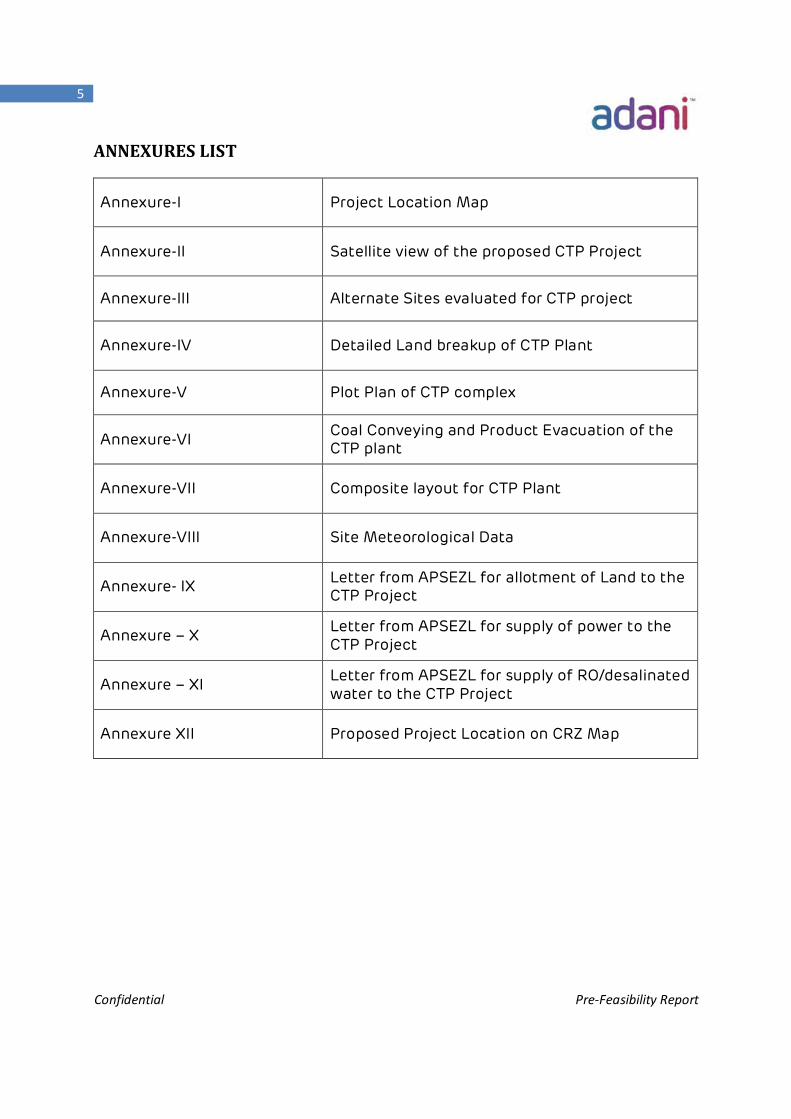
ANNEXURES LIST
Annexure-I Project Location Map
Annexure-II Satellite view of the proposed CTP Project
Annexure-III Alternate Sites evaluated for CTP project
Annexure-IV Detailed Land breakup of CTP Plant
Annexure-V Plot Plan of CTP complex
Annexure-VI Coal Conveying and Product Evacuation of the CTP plant
Annexure-VII Composite layout for CTP Plant
Annexure-VIII Site Meteorological Data
Annexure- IX Letter from APSEZL for allotment of Land to the CTP Project
Annexure – X Letter from APSEZL for supply of power to the CTP Project
Annexure – XI Letter from APSEZL for supply of RO/desalinated water to the CTP Project
Annexure XII Proposed Project Location on CRZ Map
Confidential Pre-Feasibility Report
6
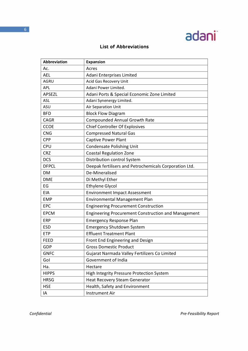
List of Abbreviations
Abbreviation Expansion Ac. Acres AEL Adani Enterprises Limited AGRU Acid Gas Recovery Unit APL Adani Power Limited. APSEZL Adani Ports & Special Economic Zone Limited ASL Adani Synenergy Limited. ASU Air Separation Unit BFD Block Flow Diagram CAGR Compounded Annual Growth Rate CCOE Chief Controller Of Explosives CNG Compressed Natural Gas CPP Captive Power Plant CPU Condensate Polishing Unit CRZ Coastal Regulation Zone DCS Distribution control System DFPCL Deepak fertilisers and Petrochemicals Corporation Ltd. DM De-Mineralised DME Di Methyl Ether EG Ethylene Glycol EIA Environment Impact Assessment EMP Environmental Management Plan EPC Engineering Procurement Construction EPCM Engineering Procurement Construction and Management ERP Emergency Response Plan ESD Emergency Shutdown System ETP Effluent Treatment Plant FEED Front End Engineering and Design GDP Gross Domestic Product GNFC Gujarat Narmada Valley Fertilizers Co Limited GoI Government of India Ha. Hectare HIPPS High Integrity Pressure Protection System HRSG Heat Recovery Steam Generator HSE Health, Safety and Environment IA Instrument Air
Confidential Pre-Feasibility Report
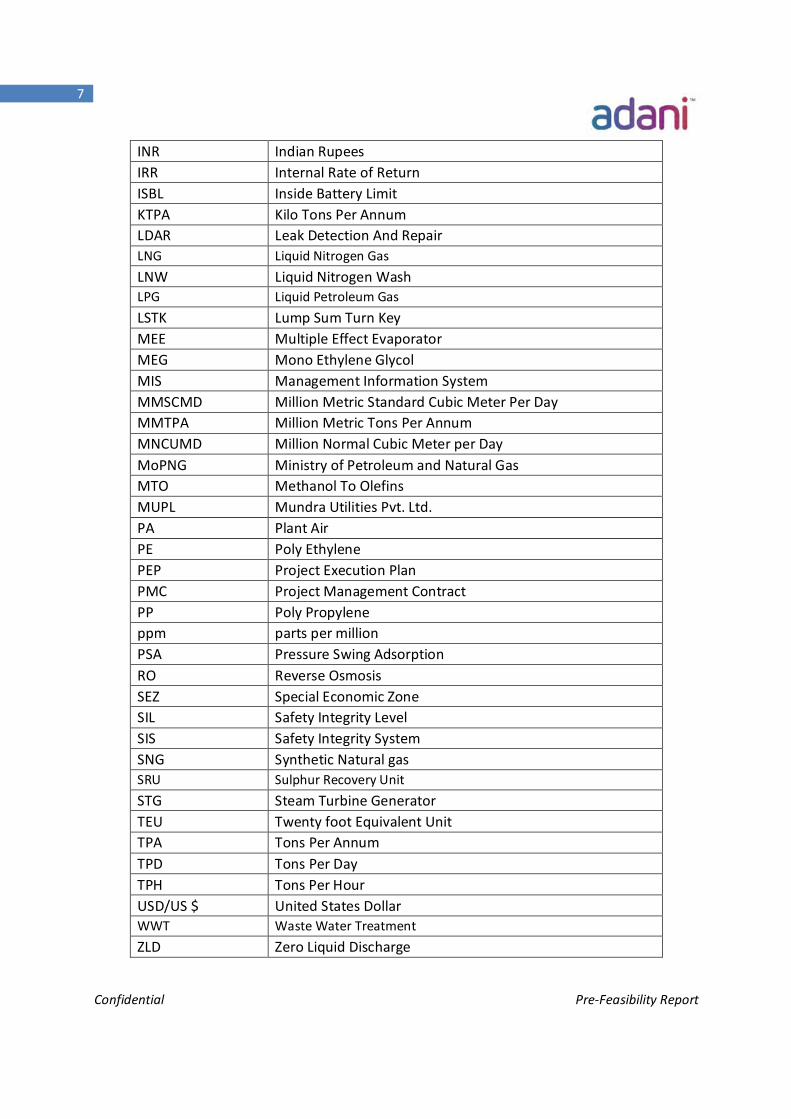
7
INR Indian Rupees IRR Internal Rate of Return ISBL Inside Battery Limit KTPA Kilo Tons Per Annum LDAR Leak Detection And Repair LNG Liquid Nitrogen Gas LNW Liquid Nitrogen Wash LPG Liquid Petroleum Gas LSTK Lump Sum Turn Key MEE Multiple Effect Evaporator MEG Mono Ethylene Glycol MIS Management Information System MMSCMD Million Metric Standard Cubic Meter Per Day MMTPA Million Metric Tons Per Annum MNCUMD Million Normal Cubic Meter per Day MoPNG Ministry of Petroleum and Natural Gas MTO Methanol To Olefins MUPL Mundra Utilities Pvt. Ltd. PA Plant Air PE Poly Ethylene PEP Project Execution Plan PMC Project Management Contract PP Poly Propylene ppm parts per million PSA Pressure Swing Adsorption RO Reverse Osmosis SEZ Special Economic Zone SIL Safety Integrity Level SIS Safety Integrity System SNG Synthetic Natural gas SRU Sulphur Recovery Unit STG Steam Turbine Generator TEU Twenty foot Equivalent Unit TPA Tons Per Annum TPD Tons Per Day TPH Tons Per Hour USD/US $ United States Dollar WWT Waste Water Treatment ZLD Zero Liquid Discharge
Confidential Pre-Feasibility Report
8
Chapter -1 Executive Summary
Confidential Pre-Feasibility Report
9
Executive Summary 1. Executive Summary
1.1 Introduction
About ADANI Group
The Adani Group is one of India’s leading business houses with revenue of about US $12
billion for financial year 2016. Adani is a global integrated infrastructure player with
businesses spanning coal trading, coal mining, oil & gas exploration, ports, multi-modal
logistics, power generation & transmission, Agro business and gas distribution.
Since Adani group’s Inception in 1988, its revenue, assets and market capitalization have
increased exponentially. After creating its mark in India, Adani has expanded its operation
to Indonesia and Australia by acquiring coal mines and ports.
The four companies of the group i.e. Adani Enterprises Ltd., Adani Ports & SEZ, Adani
Power and Adani Transmission are listed on the Indian Stock Exchanges.
Adani group has significant interest to diversify into coal to chemical business which
creates a unique integration by producing valuable chemicals through utilization of coal
from Adani owned Australian coal mines. In this context, Adani is planning to set-up up a
Coal to Poly-generation (CTP) project at Mundra. The proposed CTP project will produce
chemicals and fuels that are currently being imported to the country. Thus the project not
only contributes to the regional economic prosperity but also saves precious foreign
exchange to the exchequer of the country
Adani Synenergy Limited, 100% subsidiary company of Adani Enterprises Limited was
created to Conceptualize and Execute the envisaged Coal to Poly-generation (CTP) project
at Mundra, Gujarat.
Confidential Pre-Feasibility Report
10
1.2 Brief Description:
The proposed CTP project will employ state of art and environment friendly coal gasification
technology that converts coal to syngas (synthesis gas). The syngas produced will be utilized to
manufacture valuable downstream chemicals & fuels like Substitute Natural Gas (SNG),
Ammonia, Methanol, Acetic Acid, Poly-Olefins, MEG (Mono Ethylene Glycol), and DME (Di
Methyl Ether). The project constitutes process units like Air Separation Unit, Coal Preparation
and Handling, Coal gasification, Syngas Conditioning and Purification, Ammonia synthesis,
Methanol synthesis, SNG Synthesis (Methanation), Methanol to Acetic Acid, Syngas to MEG,
Methanol to Poly-olefins , Methanol to DME Units. The estimated project cost is around US $ 15
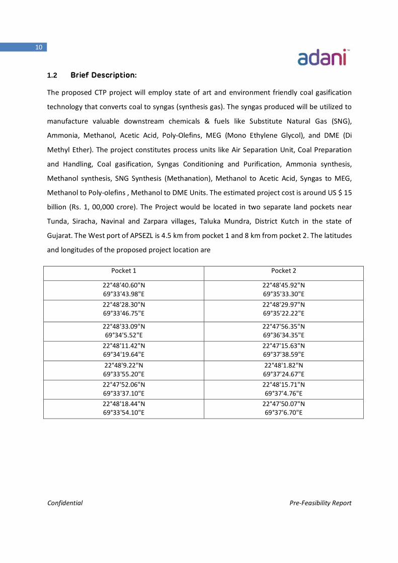
billion (Rs. 1, 00,000 crore). The Project would be located in two separate land pockets near
Tunda, Siracha, Navinal and Zarpara villages, Taluka Mundra, District Kutch in the state of
Gujarat. The West port of APSEZL is 4.5 km from pocket 1 and 8 km from pocket 2. The latitudes
and longitudes of the proposed project location are
Pocket 1 Pocket 2
22°48'40.60"N 69°33'43.98"E
22°48'45.92"N 69°35'33.30"E
22°48'28.30"N 69°33'46.75"E
22°48'29.97"N 69°35'22.22"E
22°48'33.09"N 69°34'5.52"E
22°47'56.35"N 69°36'34.35"E
22°48'11.42"N 69°34'19.64"E
22°47'15.63"N 69°37'38.59"E
22°48'9.22"N 69°33'55.20"E
22°48'1.82"N 69°37'24.67"E
22°47'52.06"N 69°33'37.10"E
22°48'15.71"N 69°37'4.76"E
22°48'18.44"N 69°33'54.10"E
22°47'50.07"N 69°37'6.70"E
Confidential Pre-Feasibility Report
11
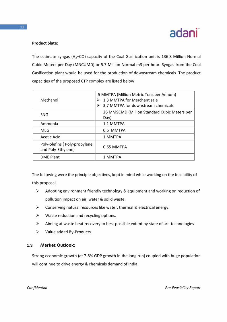
Product Slate:
The estimate syngas (H2+CO) capacity of the Coal Gasification unit is 136.8 Million Normal
Cubic Meters per Day (MNCUMD) or 5.7 Million Normal m3 per hour. Syngas from the Coal
Gasification plant would be used for the production of downstream chemicals. The product
capacities of the proposed CTP complex are listed below
The following were the principle objectives, kept in mind while working on the feasibility of
this proposal,
Adopting environment friendly technology & equipment and working on reduction of
pollution impact on air, water & solid waste.
Conserving natural resources like water, thermal & electrical energy.
Waste reduction and recycling options.
Aiming at waste heat recovery to best possible extent by state of art technologies
Value added By-Products.
1.3 Market Outlook:
Strong economic growth (at 7-8% GDP growth in the long run) coupled with huge population
will continue to drive energy & chemicals demand of India.
Methanol 5 MMTPA (Million Metric Tons per Annum) 1.3 MMTPA for Merchant sale 3.7 MMTPA for downstream chemicals
SNG 26 MMSCMD (Million Standard Cubic Meters per Day)
Ammonia 1.1 MMTPA MEG 0.6 MMTPA Acetic Acid 1 MMTPA
Poly-olefins ( Poly-propylene and Poly-Ethylene) 0.65 MMTPA
DME Plant 1 MMTPA
Confidential Pre-Feasibility Report
12
India having Natural Gas (NG) share in primary energy mix at 6 to 7 percent in 2015–16
(against the world average of 21 percent) and aspiring to reach 15 percent in the next three
to five years. India is importing more than 60 MMSCMD of Natural Gas annually to cater to
the energy requirement of the country. Current imports of LNG (Liquefied Natural Gas) are
on long term contract basis from the likes of Qatar and Middle East nations leaving us
exposed to the market Uncertainties and price volatilities.
SNG produced from the CTP project would be replacing the imported LNG thereby reducing
import bill and freeing us from market uncertainties and price volatilities. In Western India,
there is already a well-established infrastructure for gas distribution. The SNG produced
from ASL’s CTP Complex would reach the market easily using the national gas grid through
upcoming NG pipeline that would pass through Bhuj.
Similar to LNG, India is also heavily dependent on other countries for Key
chemicals/Petrochemicals. With the projected growth rate of ~ 12-13 percent, the demand-
supply gap for the chemicals is bound to increase further. ASL’s other CTP Products –
Methanol, Acetic Acid, DME, Ammonia, MEG, Poly-olefins can be easily absorbed in the
domestic market considering the projected demand–supply gap of these chemicals in 2020.
For the most of the CTP products, the current demand supply gap in the country will absorb
the products produced. Ammonia would be evacuated through sea while other products will
be dispatched through rail
Further, the advanced cutting edge, state-of-the-art technology of the CTP project will result
in superior product quality, which will provide easy market penetration of the products in
India.
Location of the proposed CTP plant near the Mundra Port would have significant logistic
advantages, through which coal (main feed stock) would be imported and the products can
be dispatched to various markets/regions across the country.
Confidential Pre-Feasibility Report
13
1.4 Process Description:
In the Gasification Unit, coal is converted to Raw Syngas in the presence of oxygen at higher
temperature and pressure. The Raw Syngas produced from the Gasifier would be cleaned in
subsequent syngas purification section to produce pure Syngas. The treated syngas is
processed in the respective downstream plants to produce SNG, Ammonia, Methanol and
MEG. Methanol is further processed in downstream units to produce Poly-olefins, Acetic
Acid & DME. The impure gases removed from the syngas cleaning section are processed
further to produce by-products such as Sulphur.
1.4.1 Process Units of CTP Complex:
The process route that CTP plant would be following is mention below:
Air Separation Unit (ASU)
Coal Preparation and Coal Handling
Coal Gasification and Scrubbing
Syngas Conditioning and Cleanup
o Sour Shift Unit
o Acid Gas Removal Unit (AGRU)
o Sulphur Recovery Unit (SRU)
o Liquid Nitrogen Wash (LNW)
o CO Cold Box & Pressure Swing Adsorption (PSA)
Methanation / SNG synthesis
Methanol synthesis
Ammonia Synthesis
Syngas to MEG
Syngas to Acetic Acid
Methanol to DME
Methanol to Olefins to PE (Polyethylene) &PP (Polypropylene)
Confidential Pre-Feasibility Report
14
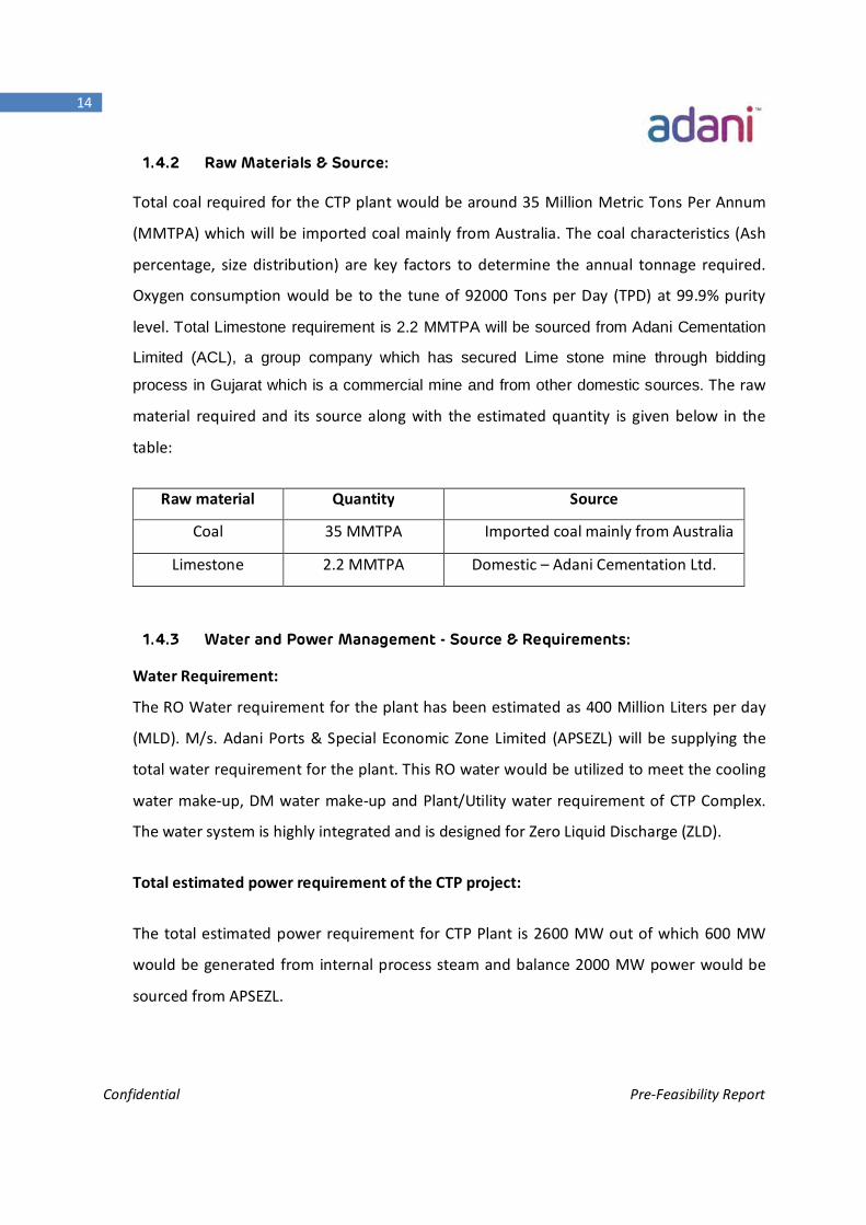
1.4.2 Raw Materials & Source:
Total coal required for the CTP plant would be around 35 Million Metric Tons Per Annum
(MMTPA) which will be imported coal mainly from Australia. The coal characteristics (Ash
percentage, size distribution) are key factors to determine the annual tonnage required.
Oxygen consumption would be to the tune of 92000 Tons per Day (TPD) at 99.9% purity
level. Total Limestone requirement is 2.2 MMTPA will be sourced from Adani Cementation
Limited (ACL), a group company which has secured Lime stone mine through bidding
process in Gujarat which is a commercial mine and from other domestic sources. The raw
material required and its source along with the estimated quantity is given below in the
table:
Raw material Quantity Source
Coal 35 MMTPA Imported coal mainly from Australia
Limestone 2.2 MMTPA Domestic – Adani Cementation Ltd.
1.4.3 Water and Power Management - Source & Requirements:
Water Requirement:
The RO Water requirement for the plant has been estimated as 400 Million Liters per day
(MLD). M/s. Adani Ports & Special Economic Zone Limited (APSEZL) will be supplying the
total water requirement for the plant. This RO water would be utilized to meet the cooling
water make-up, DM water make-up and Plant/Utility water requirement of CTP Complex.
The water system is highly integrated and is designed for Zero Liquid Discharge (ZLD).
Total estimated power requirement of the CTP project:
The total estimated power requirement for CTP Plant is 2600 MW out of which 600 MW
would be generated from internal process steam and balance 2000 MW power would be
sourced from APSEZL.
Confidential Pre-Feasibility Report
15
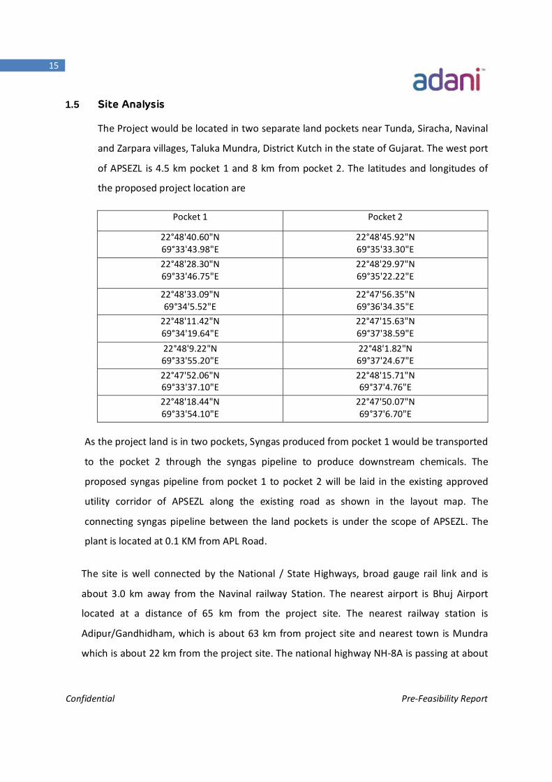
1.5 Site Analysis
The Project would be located in two separate land pockets near Tunda, Siracha, Navinal
and Zarpara villages, Taluka Mundra, District Kutch in the state of Gujarat. The west port
of APSEZL is 4.5 km pocket 1 and 8 km from pocket 2. The latitudes and longitudes of
the proposed project location are
Pocket 1 Pocket 2
22°48'40.60"N 69°33'43.98"E
22°48'45.92"N 69°35'33.30"E
22°48'28.30"N 69°33'46.75"E
22°48'29.97"N 69°35'22.22"E
22°48'33.09"N 69°34'5.52"E
22°47'56.35"N 69°36'34.35"E
22°48'11.42"N 69°34'19.64"E
22°47'15.63"N 69°37'38.59"E
22°48'9.22"N 69°33'55.20"E
22°48'1.82"N 69°37'24.67"E
22°47'52.06"N 69°33'37.10"E
22°48'15.71"N 69°37'4.76"E
22°48'18.44"N 69°33'54.10"E
22°47'50.07"N 69°37'6.70"E
As the project land is in two pockets, Syngas produced from pocket 1 would be transported
to the pocket 2 through the syngas pipeline to produce downstream chemicals. The
proposed syngas pipeline from pocket 1 to pocket 2 will be laid in the existing approved
utility corridor of APSEZL along the existing road as shown in the layout map. The
connecting syngas pipeline between the land pockets is under the scope of APSEZL. The
plant is located at 0.1 KM from APL Road.
The site is well connected by the National / State Highways, broad gauge rail link and is
about 3.0 km away from the Navinal railway Station. The nearest airport is Bhuj Airport
located at a distance of 65 km from the project site. The nearest railway station is
Adipur/Gandhidham, which is about 63 km from project site and nearest town is Mundra
which is about 22 km from the project site. The national highway NH-8A is passing at about
Confidential Pre-Feasibility Report
16
10 km away from the site. State Highway SH-6 is adjacent at north of proposed site. The site
is well connected with Ahmedabad city located at about 460 km.
The area earmarked for proposed CTP complex is owned by APSEZL and free from any
human activities. Rehabilitation & Resettlement measures are not necessary as there is no
Inhabitation in the earmarked area. Around 948.5 acre land would be required for entire
Complex including Greenbelt (33% of total land). The identified land is not an agricultural
land and has already been designated/ recorded as industrial land. Land for different
corridors (Power/Road/Coal Conveyor/Product transfer pipelines) would be additional.
There is no significant vegetation or habitation in the project site. The nearest significant
features from the project site are 4620 MW Adani Power Plant and Tata Power and West
Port of APSEZL. The villages which are in close proximity to the project site are near Tunda,
Siracha, Navinal and Zarpara. From South West to North East majority of area is of APSEZL
where west port is also located. The land is having undulations and minor grading will be
required.
Detailed Soil Investigation has not been carried out in the area. However, based on
available information from the nearby and adjacent power plant project, foundation
system has been envisaged as follows:
The subsoil is expected to be of good quality. The sub soil is residual in nature with
underlying rock layer. The soil in the adjacent area is medium dense silty fine to medium
sand under the top layer followed by dense to very dense silty fine to medium sand in the
lower layer. At some isolated places, stiff to hard silty clay or clayey silt may be found. The
underlying rock layer is highly weathered rock in the upper layer to moderately weathered
rock in layers below.
1.6 Proposed Infrastructure:
The proposed CTP Complex of Adani Synenergy Limited would require a total land area of
948.5 Acres (383.8 Hectares). This area is based on a plot plan of CTP complex as
Annexure-V which has been developed taking into account the CTP process facilities, the
Confidential Pre-Feasibility Report
17
site infrastructure requirement and external interfaces. These areas will be firmed up with
ongoing engineering studies to suit the facility’s operating conditions, construction and
maintenance philosophies and storage requirements.
CTP Plant area of around 322 Acres of land would comprise of facilities for Gasification
Island, ASU/Shift Converter/AGR/SRU/LNW/Cold Box/PSA, SNG Methanator, Methanol
Synthesis, Ammonia Synthesis, Syngas to MEG, Methanol to Acetic acid, DME, Methanol to
Olefins and Poly Olefins plants.
CTP Utilities include 2 X 200 TPH (Tons per Hour) Process boiler and 600MW Steam turbine
generator (STG). Other utilities include DM (De-Mineralized Water) plant, CPU (Condensate
Polishing Unit), Cooling water tank, Tank farm, Slag storage, Flare, Railway siding, Plant
Buildings such substation, Switch yard, Control room, Non-plant buildings, Roads, Pipe
Racks/Trenches & Cable Trays, Laboratories, General stores/ Warehouse, Fire & Safety
Department, Maintenance Workshop need around 313 Acres of Land.
Around 313.5 Acres (33% of total CTP Complex area) has been kept for greenbelt
development as per prevailing statutory guidelines from GSPCB/CPCB/MOE & F.
1.6.1 Social Infrastructure:
ASL believes that an effective growth policy must also be implemented for the fulfillment of
basic needs of the masses, especially of those living in rural areas.
ASL has one of the best social infrastructure programs already Implemented by Adani
Group at Mundra in the core areas of Health, Education, Sustainable livelihood & women
empowerment, Community infrastructure, Youth sport & cultural activities and Calamity
management. ASL is strictly committed and is going to implement the proposal to uplift the
social infrastructure surrounding the CTP area.
1.6.2 Industrial Waste Management:
There will not be any significant gaseous emissions from the CTP complex during normal
operation. Overall, the plant design minimizes the emissions by process integration and
Confidential Pre-Feasibility Report
18
waste heat management. The Industrial Wastes that could be generated from CTP Complex
are Slag, Solid wastes, Process Waste Water and Acid Gases. ASL adopts Zero Liquid
Discharge (ZLD) system for Process Waste Water. Besides, the gaseous emissions would be
suitably treated with latest environment technologies before discharging to the
atmosphere.
The main solid waste from the Plant is the Slag generated from the CTP complex. The total
amount of Slag generated from the CTP complex is about 9 MMTPA. The Slag is non
Leachable, non-hazardous in nature and easily conforms to regulatory limits for metals,
organics and standard waste characteristic tests for toxicity, reactivity, ignitibility, and
corrosiveness. For temporary/ emergency purposes, an area of 84 acres is considered for
slag storage pond of capacity 4.5 MMTPA which is equivalent to 6 months of slag
production. Apart from the storage, Gasifier Slag would be utilized for Road/Embankment
Making, Structural Filling, Cement Making, Land Development, Mine backfilling, synthetic
Lightweight Aggregate production etc. The other solid wastes generated like spent
catalysts, discarded resins and molecular sieves will be disposed as per hazardous waste
management rule.
The site philosophy is to minimize the consumption of RO water by maximizing the re-use
of wastewater within the CTP facility. Zero Liquid Discharge (ZLD) systems would be
adopted for CTP Complex by installing ETP (Effluent Treatment Plant), Tertiary Treatment
Plant and Multiple Effect Evaporator (MEE). Dry sludge/salts from MEE (around 13 TPH)
shall be disposed through authorized agencies as per Hazardous Waste Management
(HWM) Rule.
The generated sewage waste water would be treated in Sewage Treatment Plant and the
treated water would be utilized for Horticulture purposes.
The CTP facility would be well equipped to deal with air pollutant regulations. Under the
reducing environment inside the gasifier, majority of the Sulphur and Nitrogen in the coal is
converted into H2S and NH3, which are absorbed in the Gas Clean-Up Section. The Sulphur
Recovery unit also converts Mercaptans and COS present in the syngas into Saleable
Confidential Pre-Feasibility Report
19
Sulphur. So, the quantity of SOx & NOx in the flue gas from the CTP Complex would be
negligible. Moreover, these emissions would be limited by employing latest environmental
technologies to treat gases to the permissive levels of emissions stipulated by Central/State
Pollution Control Boards, Ministry of Environment & Forest (MOEF&CC) before releasing to
the atmosphere.
The following steps would be taken to reduce air emissions with examples of abatement
technologies:
1. Sulphur Dioxide (SO2): A Sulphur Recovery Unit for the recovery of saleable
Sulphur.
2. Particulate Matter: Wet Scrubbers, Cyclones, Electrostatic precipitators, Fabric
Filters.
3. VOC Emissions: Dual Mechanical Seals on pumps, closed vent systems, closed loop
sampling etc.
Materials expected to generate fugitive dust such as transportation of sand, soil etc. will be
transported in wet condition with covered truck to ensure that no dust is generated during
construction. Coal will be transported through fully enclosed Conveyors for ensuring
complete dust suppression, including provision for Mechanized De-dusting systems.
1.7 Rehabilitation and Resettlement (R&R) Plan:
Since there is no human Inhabitation in the selected land, no displacement and
rehabilitation of local population is necessary.
1.8 Project Schedule & Cost Estimates:
Implementation schedule for CTP complex: 48 Months
The project cost has been estimated on the basis of identified scope, engineering details for
cost estimation, licensor’s information and cost data for Engineering, Procurement and
Confidential Pre-Feasibility Report
20
Construction management (EPCM) mode of execution. A reasonable contingency factor has
been applied to take care of the unforeseen items.
The total estimated project Cost of the CTP project is around 15.0 Billion USD (Rs. 1,00,000
Cr.).
The project would create 3000 direct and 7000 indirect employment during plant
operations. Around 5000 people would be required during construction phase of the
project.
Confidential Pre-Feasibility Report
21
Chapter -2 Introduction of the Project
Confidential Pre-Feasibility Report
22
Introduction of the Project 2. INTRODUCTION OF PROJECT
2.1 Background of the Project:
Adani Group being the largest private power producer in India acquired a coal block in
Australia that will start operating soon. The mined Australian coal will be transported
through sea route and unloaded at Mundra port, owned and operated by Adani Group.
The Coal would be used as a raw material for the existing Adani’s 4620 MW Power plant
at Mundra.
India has a huge shortfall in Natural Gas and majority of chemical & petrochemical
products. For most of the chemicals and petrochemicals, current installed capacities are
likely to remain same for the foreseeable future as no capacity expansions or new
projects are in pipeline. India’s promising GDP (Gross Domestic Product) growth and
improvement in Citizens’ quality of life resulted in a significant rise in Energy and
Chemicals/petrochemicals demand. This is likely to increase the Supply/Demand gap in
key Chemicals & Petrochemicals thereby weakening the Nation’s resolve in achieving
self-sufficiency.
In this context, Adani Group is planning to come up with a project that will monetize
chemical value of the Australian coal by manufacturing key Chemicals and
Petrochemicals that are currently being imported from other countries. Thus the project
not only contributes to the regional economic prosperity but also saves precious foreign
exchange to the exchequer of the country.
Adani Synenergy Limited, 100% subsidiary company of Adani Enterprises Limited was
created to Conceptualize and Execute the envisaged Coal to Polygeneration (CTP)
project at Mundra, Gujarat.
2.2 Brief Introduction:
The CTP project cost estimated at US $ 15 billion (Rs. 100,000 crore) includes Coal
Preparation and Handling, Coal gasification and purification, Ammonia, Acetic Acid,
Confidential Pre-Feasibility Report
23
MEG, Methanol, MTO, PE, PP, DME and SNG plants. The project would employ
environment friendly coal gasification technology to convert coal into syngas. The
syngas produced will be utilized to manufacture Substitute Natural Gas (SNG) and
various Chemicals and Petrochemicals mentioned above.
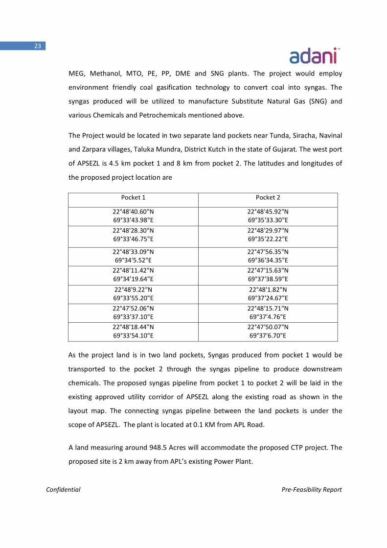
The Project would be located in two separate land pockets near Tunda, Siracha, Navinal
and Zarpara villages, Taluka Mundra, District Kutch in the state of Gujarat. The west port
of APSEZL is 4.5 km pocket 1 and 8 km from pocket 2. The latitudes and longitudes of
the proposed project location are
Pocket 1 Pocket 2
22°48'40.60"N 69°33'43.98"E
22°48'45.92"N 69°35'33.30"E
22°48'28.30"N 69°33'46.75"E
22°48'29.97"N 69°35'22.22"E
22°48'33.09"N 69°34'5.52"E
22°47'56.35"N 69°36'34.35"E
22°48'11.42"N 69°34'19.64"E
22°47'15.63"N 69°37'38.59"E
22°48'9.22"N 69°33'55.20"E
22°48'1.82"N 69°37'24.67"E
22°47'52.06"N 69°33'37.10"E
22°48'15.71"N 69°37'4.76"E
22°48'18.44"N 69°33'54.10"E
22°47'50.07"N 69°37'6.70"E
As the project land is in two land pockets, Syngas produced from pocket 1 would be
transported to the pocket 2 through the syngas pipeline to produce downstream
chemicals. The proposed syngas pipeline from pocket 1 to pocket 2 will be laid in the
existing approved utility corridor of APSEZL along the existing road as shown in the
layout map. The connecting syngas pipeline between the land pockets is under the
scope of APSEZL. The plant is located at 0.1 KM from APL Road.
A land measuring around 948.5 Acres will accommodate the proposed CTP project. The
proposed site is 2 km away from APL’s existing Power Plant.
Confidential Pre-Feasibility Report
24
M/s. Adani Ports & Special Economic Zone Limited (APSEZL) will be supplying the total
water requirement for the plant. Power also would be sourced from APSEZL
The estimate syngas (H2+CO) capacity of the Coal Gasification plant is 136.8 Million
Normal Cubic Meters per Day (MNCUMD) or 5.7 Million Normal m3 per hour. The
following are the main products of the CTP plant
The Product slate of the CTP project is chosen such that it targets key products which
India imports on a large scale.
One of the major products of CTP project is SNG. SNG has similar characteristics as
Natural Gas (NG) and can be used in all applications where NG is being used. SNG can be
used as Town Gas (cooking gas) to replace LPG (Liquefied Petroleum Gas), as
transportation Fuel (Compressed Natural Gas) to replace Petrol/Diesel.
Methanol is used for making Chemicals/Petrochemicals/Specialty Chemicals. Methanol
can be used as Petrol blend (up to 20%), which is widely practiced in China for fuel
applications. This practice not only helped china monetize Indigenous coal but also
helped curb its ever growing pollution. Following China, Govt. of India is planning to
introduce methanol blends based on the suggestions by Indian think tanks to reduce
imports and stem pollution.
Methanol 5 MMTPA 1.3 MMTPA for Merchant sale 3.7 MMTPA for downstream chemicals
SNG 26 MMSCMD Ammonia 1.1 MMTPA MEG 0.6 MMTPA Acetic Acid 1 MMTPA Poly-olefins ( Poly-propylene and Poly-Ethylene)
0.65 MMTPA
DME Plant 1 MMTPA
Confidential Pre-Feasibility Report
25
Ammonia is used for manufacturing Urea and other Complex fertilizers and India is yet
to achieve self-sufficiency in these products. MEG is the main feedstock for polyester
manufacturing and used in anti-freeze applications. PE and PP are precursors to almost
every plastic product we come across.
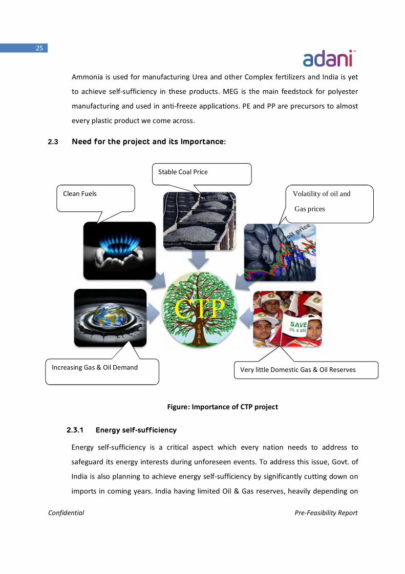
2.3 Need for the project and its Importance:
Figure: Importance of CTP project
2.3.1 Energy self-sufficiency
Energy self-sufficiency is a critical aspect which every nation needs to address to
safeguard its energy interests during unforeseen events. To address this issue, Govt. of
India is also planning to achieve energy self-sufficiency by significantly cutting down on
imports in coming years. India having limited Oil & Gas reserves, heavily depending on
CTP
Stable Coal Price
Volatility of oil and
Gas prices
Very little Domestic Gas & Oil Reserves Increasing Gas & Oil Demand
Clean Fuels
Confidential Pre-Feasibility Report
26
crude & gas imports. CTP categorically addresses this issue by replacing natural gas
imports by producing Substitute Natural gas and other key chemicals/petrochemicals.
Setting up a CTP plant in Western region of India can fully utilize the Port facility to
import feed coal and transport Methanol, Ammonia and other CTP products. The
existing state of the art port infrastructure can fully cater to the CTP demands. SNG
Produced from the CTP can be transported through the National Gas Grid to any part of
India.
2.3.2 Price volatility:
The principle interest in envisaging a project of this nature comes from the fact that
India is majorly depending on imported oil & gas and the price uncertainties associated
with them. Using low cost imported coal can allow India to minimize exposure to gas
and oil price volatilities by providing valuable products needed for economic growth.
2.3.3 Clean technology:
The gasification technology is an environment friendly process. For Coal gasification
plants, there would be minimum release of pollutants to atmosphere.
During the whole CTP process, the entire Sulphur and nitrogen present in the coal would
be converted to elemental Sulphur (final product) and Ammonia instead of SOx and NOx.
Substitute Natural Gas (SNG) is free of Sulphur/heavy hydro carbons. Use of SNG in
domestic cooking purposes is safer than use of LPG since SNG is lighter than LPG. In case
of gas leakage, SNG would be evacuated from the kitchen room through ventilator
easily, whereas LPG would be dispersed on the floor level due to high density as
compared to air. Methanol is also a very good feedstock for Chemical/Fertilizer
Industries.
2.3.4 Socio economic empowerment of the region:
This CTP project has the potential to generate 10,000 direct and indirect jobs, CTP
project will generate substantial amount of Tax Revenue.
Confidential Pre-Feasibility Report
27
In addition to the above benefits, this project will strengthen the overall socio-
economic status of the people especially from Mundra and overall Gujarat.
2.4 Demand – Supply Outlook
An overview of Chinese Coal based SNG/Chemicals development
The defined shift in China from conventionally produced chemicals to coal derived
chemicals is one of the most significant changes in energy sector. This change brought
about import substitution by monetizing indigenous coal to make up for limited oil and
gas reserves.
2.4.1 An overview of Natural Gas in India
Current global attention on reducing the carbon emissions is making way for renewable
energy by limiting coal based energy. India too has set goals for curbing the carbon
emissions by augmenting renewables share in its Energy basket. Apart from the
renewables, Govt. of India is also planning to increase the share of gas based energy.
While this move looks promising, India needs to Import huge quantities of LNG for
meeting this target.
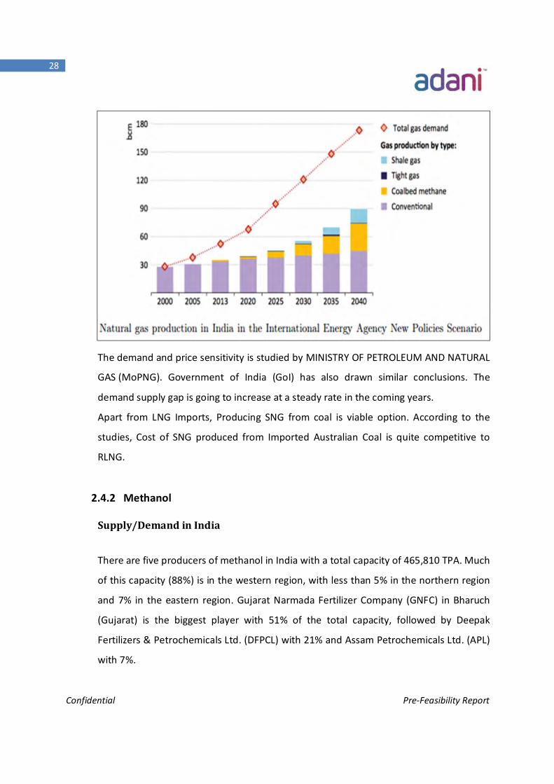
For Natural gas, the total production was around 85 MMSCMD against the demand of
145 MMSCMD. India is meeting the demand-supply gap by importing e.g. in 2016, the
imports are to the tune 60 MMSCMD. Import dependency has uncertainty attached to it
and subjective to price volatility. Thus, our energy future is at considerable risk besides a
large Foreign Exchange flow adversely affecting our Foreign Exchange Revenue.
Confidential Pre-Feasibility Report
28
The demand and price sensitivity is studied by MINISTRY OF PETROLEUM AND NATURAL
GAS (MoPNG). Government of India (GoI) has also drawn similar conclusions. The
demand supply gap is going to increase at a steady rate in the coming years.
Apart from LNG Imports, Producing SNG from coal is viable option. According to the
studies, Cost of SNG produced from Imported Australian Coal is quite competitive to
RLNG.
2.4.2 Methanol
Supply/Demand in India
There are five producers of methanol in India with a total capacity of 465,810 TPA. Much
of this capacity (88%) is in the western region, with less than 5% in the northern region
and 7% in the eastern region. Gujarat Narmada Fertilizer Company (GNFC) in Bharuch
(Gujarat) is the biggest player with 51% of the total capacity, followed by Deepak
Fertilizers & Petrochemicals Ltd. (DFPCL) with 21% and Assam Petrochemicals Ltd. (APL)
with 7%.
Confidential Pre-Feasibility Report
29
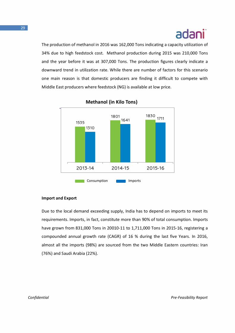
The production of methanol in 2016 was 162,000 Tons indicating a capacity utilization of
34% due to high feedstock cost. Methanol production during 2015 was 210,000 Tons
and the year before it was at 307,000 Tons. The production figures clearly indicate a
downward trend in utilization rate. While there are number of factors for this scenario
one main reason is that domestic producers are finding it difficult to compete with
Middle East producers where feedstock (NG) is available at low price.
Import and Export
Due to the local demand exceeding supply, India has to depend on imports to meet its
requirements. Imports, in fact, constitute more than 90% of total consumption. Imports
have grown from 831,000 Tons in 20010-11 to 1,711,000 Tons in 2015-16, registering a
compounded annual growth rate (CAGR) of 16 % during the last five Years. In 2016,
almost all the imports (98%) are sourced from the two Middle Eastern countries: Iran
(76%) and Saudi Arabia (22%).
Methanol (in Kilo Tons)
1535
1801 1830
1310
1641 1711
2013-14 2014-15 2015-16
Consumption Imports
Confidential Pre-Feasibility Report
30
Future Demand:
Demand for methanol five years hence is projected to grow at an average growth rate of
6% per annum. The demand does not take into account the potential demand that may
arise from the biodiesel and fuel blending sectors.
A potential demand based on blending 20% of gasoline output with 15% of methanol
could be around 4 MMTPA annually. NITI Aayog is already working on Plan for Methanol
blending in Gasoline.
With no new capacities announced, and none expected due to low cost natural gas
based methanol available in the country, India will have to continue depending heavily
on imports. There is a need for world scale plant-based on low cost natural gas
availability, or on alternate low value hydrocarbons such as Coal gasification.
Methanol produced from CTP would reduce the Imports by 1.3 MMTPA (75% of
Imports)
2.4.3 DME
Dimethyl ether (DME) is a clean-burning fuel that is typically produced from methanol.
DME is considered a viable substitute for LPG. Apart from LPG, DME is an Excellent
Diesel Fuel substitute with a Cetane No. of 55-60 (45-55 for regular diesel).
While World DME demand is around 3.6 MMTPA in 2016, China alone accounts for 90%
of the demand. 90% China’s DME demand is driven by blending with LPG. China
practices DME blending with LPG to reduce its import dependency and create energy
security through utilization of Indigenous coal reserves
Indian Context:
Following china, Indian govt. is also planning to come up with a frame work for
developing India as Methanol based economy. DME is produced from methanol and
DME blending in the LPG and Diesel is a likely scenario in the coming years.
Govt. think tank NITI Aayog is advocating DME blending in LPG among others. This could
push the DME demand significantly. India’s current LPG consumption is around 21
MMTPA and blending 20% in LPG requires around 4 Million tons DME.
Confidential Pre-Feasibility Report
31
1 MMTPA DME produced from the CTP can cater to the India’s entire DME needs
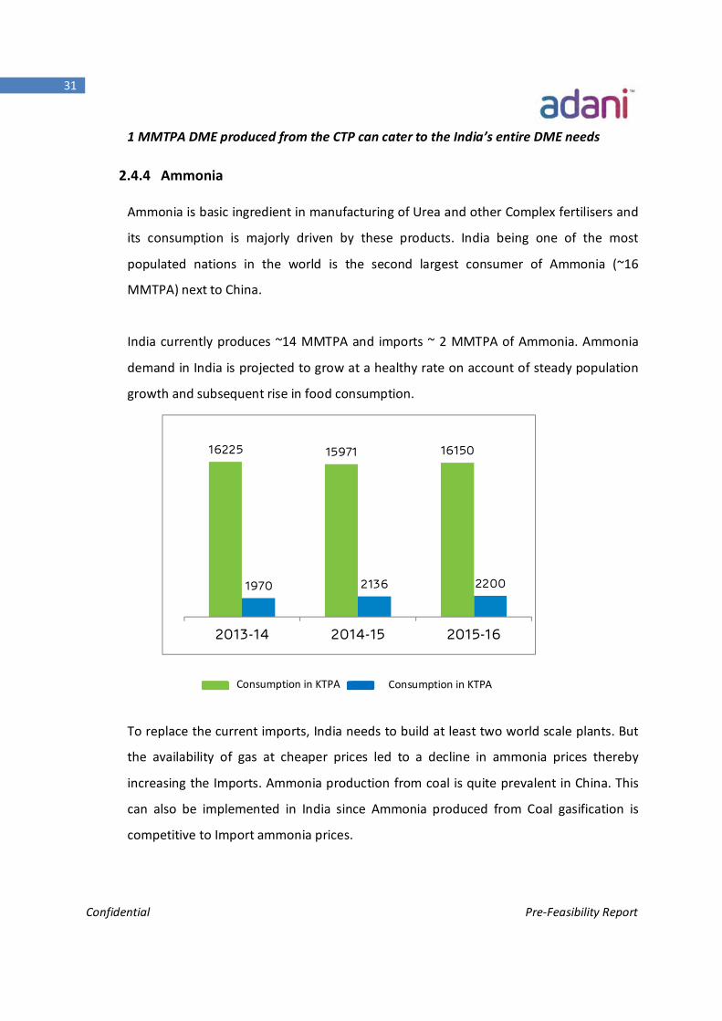
2.4.4 Ammonia
Ammonia is basic ingredient in manufacturing of Urea and other Complex fertilisers and
its consumption is majorly driven by these products. India being one of the most
populated nations in the world is the second largest consumer of Ammonia (~16
MMTPA) next to China.
India currently produces ~14 MMTPA and imports ~ 2 MMTPA of Ammonia. Ammonia
demand in India is projected to grow at a healthy rate on account of steady population
growth and subsequent rise in food consumption.
To replace the current imports, India needs to build at least two world scale plants. But
the availability of gas at cheaper prices led to a decline in ammonia prices thereby
increasing the Imports. Ammonia production from coal is quite prevalent in China. This
can also be implemented in India since Ammonia produced from Coal gasification is
competitive to Import ammonia prices.
16225 15971 16150
1970 2136 2200
2013-14 2014-15 2015-16
Consumption in KTPA
Consumption in KTPA
Confidential Pre-Feasibility Report
32
The Ammonia Produced from the CTP Project would help India cut imports by half (1
MMTPA).
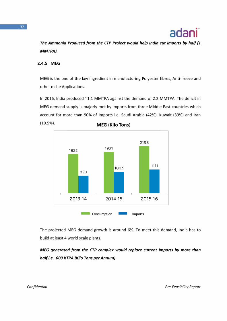
2.4.5 MEG
MEG is the one of the key ingredient in manufacturing Polyester fibres, Anti-freeze and
other niche Applications.
In 2016, India produced ~1.1 MMTPA against the demand of 2.2 MMTPA. The deficit in
MEG demand-supply is majorly met by imports from three Middle East countries which
account for more than 90% of Imports i.e. Saudi Arabia (42%), Kuwait (39%) and Iran
(10.5%).
The projected MEG demand growth is around 6%. To meet this demand, India has to
build at least 4 world scale plants.
MEG generated from the CTP complex would replace current Imports by more than
half i.e. 600 KTPA (Kilo Tons per Annum)
MEG (Kilo Tons)
1822 19312198
8201003 1111
2013-14 2014-15 2015-16
Consumption Imports
Confidential Pre-Feasibility Report
33
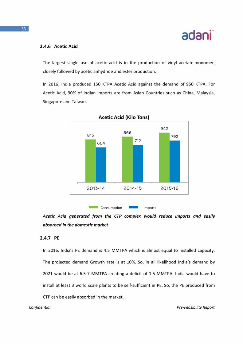
2.4.6 Acetic Acid
The largest single use of acetic acid is in the production of vinyl acetate monomer,
closely followed by acetic anhydride and ester production.
In 2016, India produced 150 KTPA Acetic Acid against the demand of 950 KTPA. For
Acetic Acid, 90% of Indian imports are from Asian Countries such as China, Malaysia,
Singapore and Taiwan.
Acetic Acid generated from the CTP complex would reduce imports and easily
absorbed in the domestic market
2.4.7 PE
In 2016, India’s PE demand is 4.5 MMTPA which is almost equal to Installed capacity.
The projected demand Growth rate is at 10%. So, in all likelihood India’s demand by
2021 would be at 6.5-7 MMTPA creating a deficit of 1.5 MMTPA. India would have to
install at least 3 world scale plants to be self-sufficient in PE. So, the PE produced from
CTP can be easily absorbed in the market.
Acetic Acid (Kilo Tons)
815866
942
664 712792
2013-14 2014-15 2015-16
Consumption Imports
Confidential Pre-Feasibility Report
34
2.4.8 PP
In 2016, India’s PP demand is 4.1 MMTPA Installed capacities. The projected demand
Growth rate is set at 12%. So, India’s demand by 2021 would be around 6.5-7 MMTPA.
Though, New PP projects are announced in last few years, most of them have not
materialized. By, 2021 India would have to install at least 1-2 world scale plants to be
self-sufficient in PP. So, the PP produced form the CTP can be easily absorbed in
Domestic market.
Conclusion:
Based on the above facts and figures, it can be concluded that India market can easily
absorb all the CTP products.
2.5 Employment generation:
During normal operation of the CTP Plant around 3000 people would be employed
directly and around 7000 people indirectly.
During the construction phase of the CTP project, the project would employ a minimum
of 5000 workers in various tasks.
Confidential Pre-Feasibility Report
35
Chapter -3 Process Description
Confidential Pre-Feasibility Report
36
Process Description
3. PROCESS DESCRIPTION
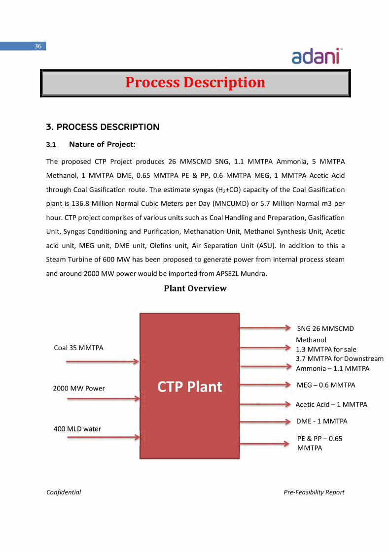
3.1 Nature of Project:
The proposed CTP Project produces 26 MMSCMD SNG, 1.1 MMTPA Ammonia, 5 MMTPA
Methanol, 1 MMTPA DME, 0.65 MMTPA PE & PP, 0.6 MMTPA MEG, 1 MMTPA Acetic Acid
through Coal Gasification route. The estimate syngas (H2+CO) capacity of the Coal Gasification
plant is 136.8 Million Normal Cubic Meters per Day (MNCUMD) or 5.7 Million Normal m3 per
hour. CTP project comprises of various units such as Coal Handling and Preparation, Gasification
Unit, Syngas Conditioning and Purification, Methanation Unit, Methanol Synthesis Unit, Acetic
acid unit, MEG unit, DME unit, Olefins unit, Air Separation Unit (ASU). In addition to this a
Steam Turbine of 600 MW has been proposed to generate power from internal process steam
and around 2000 MW power would be imported from APSEZL Mundra.
Plant Overview
CTP Plant
Methanol 1.3 MMTPA for sale 3.7 MMTPA for Downstream chemials Ammonia – 1.1 MMTPA
DME - 1 MMTPA
MEG – 0.6 MMTPA
Acetic Acid – 1 MMTPA
PE & PP – 0.65 MMTPA
SNG 26 MMSCMD
Coal 35 MMTPA
2000 MW Power
400 MLD water
Confidential Pre-Feasibility Report
37
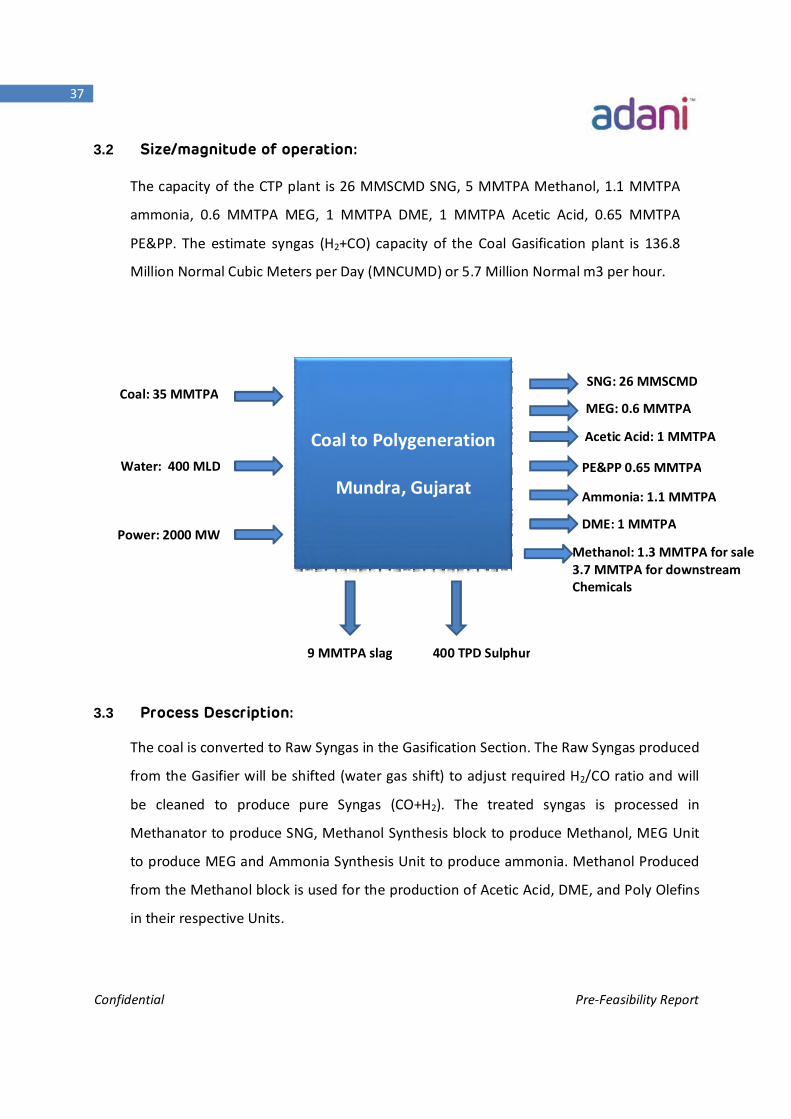
3.2 Size/magnitude of operation:
The capacity of the CTP plant is 26 MMSCMD SNG, 5 MMTPA Methanol, 1.1 MMTPA
ammonia, 0.6 MMTPA MEG, 1 MMTPA DME, 1 MMTPA Acetic Acid, 0.65 MMTPA
PE&PP. The estimate syngas (H2+CO) capacity of the Coal Gasification plant is 136.8
Million Normal Cubic Meters per Day (MNCUMD) or 5.7 Million Normal m3 per hour.
3.3 Process Description:
The coal is converted to Raw Syngas in the Gasification Section. The Raw Syngas produced
from the Gasifier will be shifted (water gas shift) to adjust required H2/CO ratio and will
be cleaned to produce pure Syngas (CO+H2). The treated syngas is processed in
Methanator to produce SNG, Methanol Synthesis block to produce Methanol, MEG Unit
to produce MEG and Ammonia Synthesis Unit to produce ammonia. Methanol Produced
from the Methanol block is used for the production of Acetic Acid, DME, and Poly Olefins
in their respective Units.
9 MMTPA slag
Coal to Polygeneration
Mundra, Gujarat
400 TPD Sulphur
SNG: 26 MMSCMD
Methanol: 1.3 MMTPA for sale3.7 MMTPA for downstream Chemicals .7 MMTPA for Downstream
DME: 1 MMTPA
Coal: 35 MMTPA
Water: 400 MLD
Power: 2000 MW
Ammonia: 1.1 MMTPA
MEG: 0.6 MMTPA
Acetic Acid: 1 MMTPA
PE&PP 0.65 MMTPA
Confidential Pre-Feasibility Report
38
3.3.1 Process Route:
Air Separation Unit
Coal Preparation Plant (Conveyance, Size Reduction, Storage Facility & Preparation)
Coal Gasification Unit
Syngas conditioning and Cleanup
a. Sour Shift Unit
b. Acid Gas Removal Unit (AGRU)
c. Sulphur Recovery Unit (SRU)
d. Liquid Nitrogen Wash (LNW)
e. Cold Box (CB) & Pressure Swing Adsorption (PSA)
Methanol Synthesis Unit
SNG Plant
Ammonia Plant
MEG Plant
Acetic Acid Plant
Methanol to Olefins and Poly Olefins
DME Plant
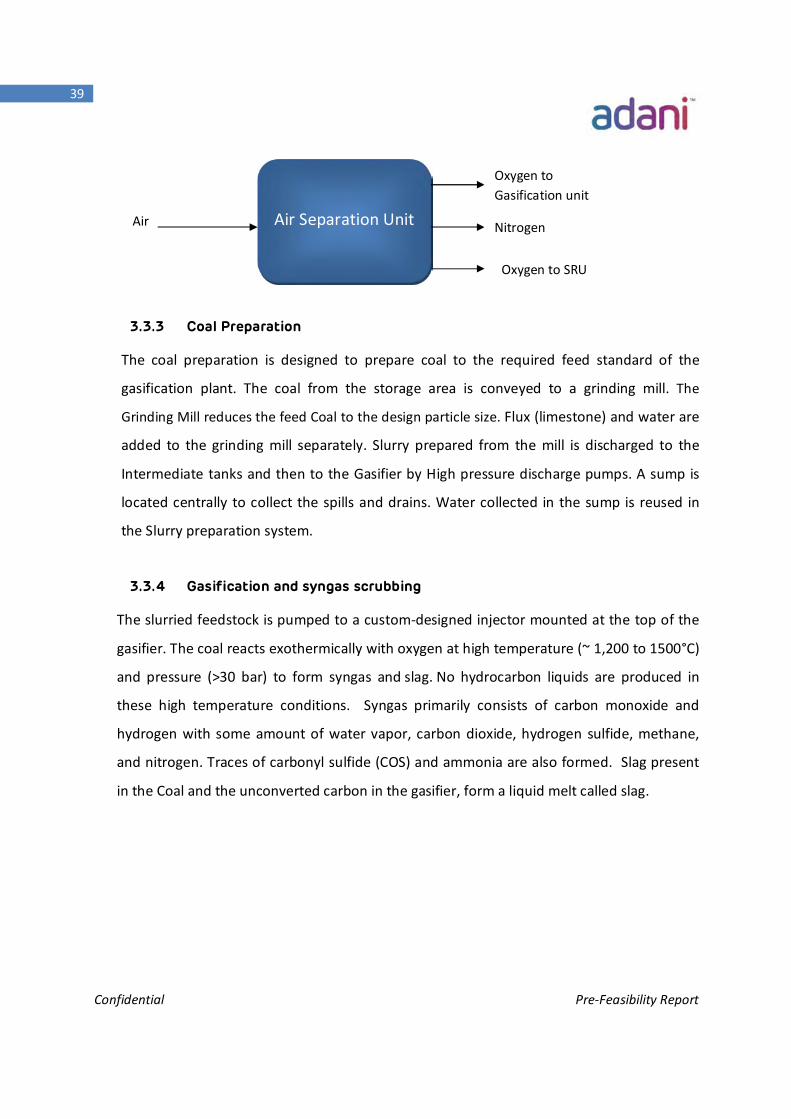
3.3.2 ASU (Air Separation Unit)
The Gasification Process of the Plant will use pure oxygen to limit inert gases (argon and
nitrogen) in the product syngas. Oxygen is provided to the Gasifiers battery limit by a
cryogenic air separation unit (ASU) supplied by a suitable process licensor. To maintain
reasonable size and energy consumption of the ASU, oxygen purity of about 99.9 mol % is
selected. ASU also supplies high pressure (HP) and low pressure (LP) gaseous nitrogen for
use within the gasification facility. Typically, the nitrogen requirement for the Gasification
Island can be easily met by the ASU with no additional capital investment since nitrogen is a
by-product of the Facility.
Confidential Pre-Feasibility Report
39
3.3.3 Coal Preparation
The coal preparation is designed to prepare coal to the required feed standard of the
gasification plant. The coal from the storage area is conveyed to a grinding mill. The
Grinding Mill reduces the feed Coal to the design particle size. Flux (limestone) and water are
added to the grinding mill separately. Slurry prepared from the mill is discharged to the
Intermediate tanks and then to the Gasifier by High pressure discharge pumps. A sump is
located centrally to collect the spills and drains. Water collected in the sump is reused in
the Slurry preparation system.
3.3.4 Gasification and syngas scrubbing
The slurried feedstock is pumped to a custom-designed injector mounted at the top of the
gasifier. The coal reacts exothermically with oxygen at high temperature (~ 1,200 to 1500°C)
and pressure (>30 bar) to form syngas and slag. No hydrocarbon liquids are produced in
these high temperature conditions. Syngas primarily consists of carbon monoxide and
hydrogen with some amount of water vapor, carbon dioxide, hydrogen sulfide, methane,
and nitrogen. Traces of carbonyl sulfide (COS) and ammonia are also formed. Slag present
in the Coal and the unconverted carbon in the gasifier, form a liquid melt called slag.
Air
Air Separation Unit
Oxygen to Gasification unit
Nitrogen
Oxygen to SRU
Confidential Pre-Feasibility Report
40
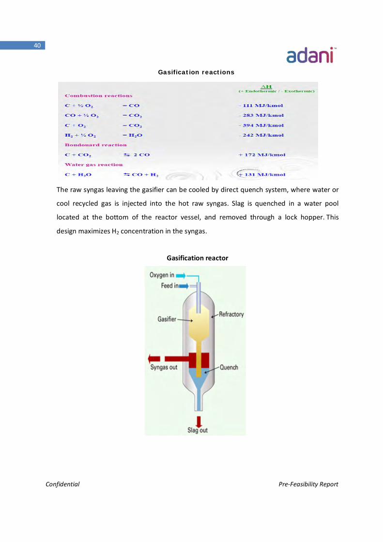
Gasification reactions
The raw syngas leaving the gasifier can be cooled by direct quench system, where water or
cool recycled gas is injected into the hot raw syngas. Slag is quenched in a water pool
located at the bottom of the reactor vessel, and removed through a lock hopper. This
design maximizes H2 concentration in the syngas.
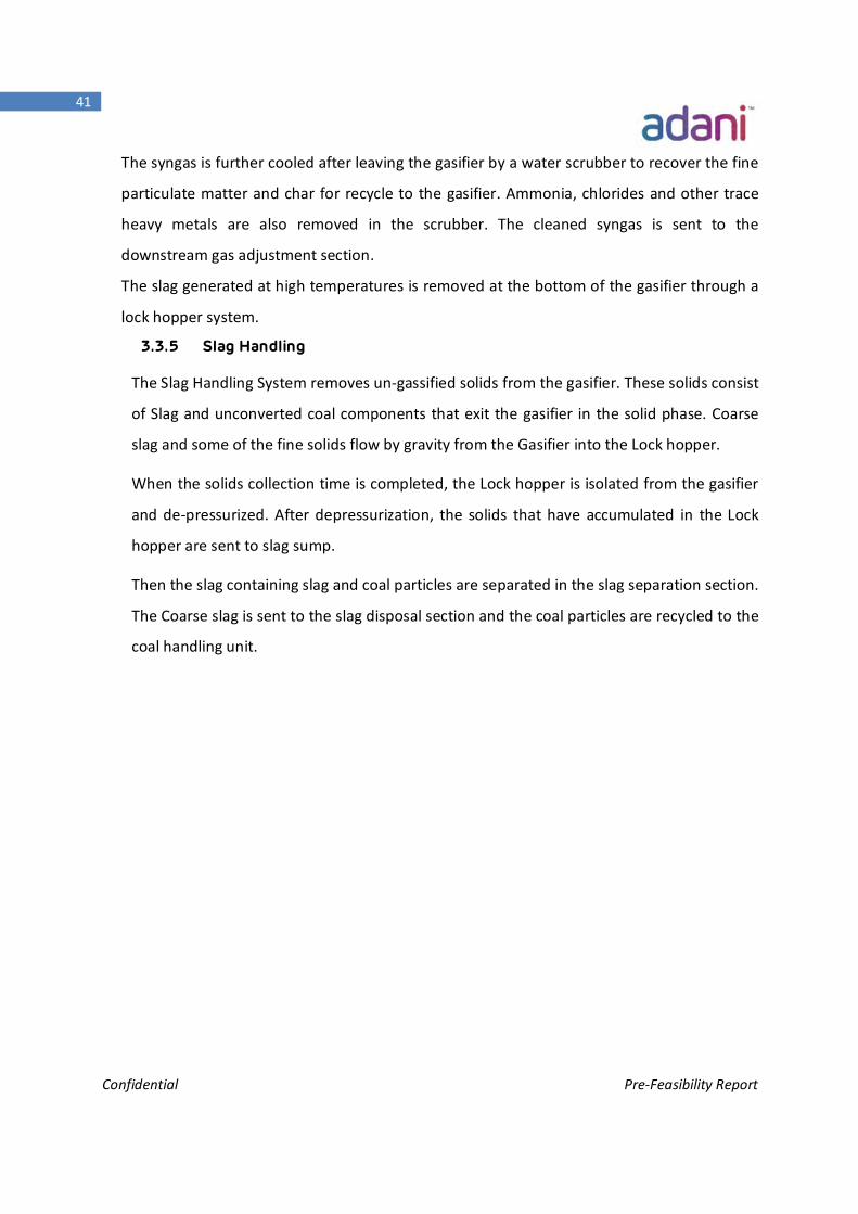
Gasification reactor
Confidential Pre-Feasibility Report
41
The syngas is further cooled after leaving the gasifier by a water scrubber to recover the fine
particulate matter and char for recycle to the gasifier. Ammonia, chlorides and other trace
heavy metals are also removed in the scrubber. The cleaned syngas is sent to the
downstream gas adjustment section.
The slag generated at high temperatures is removed at the bottom of the gasifier through a
lock hopper system.
3.3.5 Slag Handling
The Slag Handling System removes un-gassified solids from the gasifier. These solids consist
of Slag and unconverted coal components that exit the gasifier in the solid phase. Coarse
slag and some of the fine solids flow by gravity from the Gasifier into the Lock hopper.
When the solids collection time is completed, the Lock hopper is isolated from the gasifier
and de-pressurized. After depressurization, the solids that have accumulated in the Lock
hopper are sent to slag sump.
Then the slag containing slag and coal particles are separated in the slag separation section.
The Coarse slag is sent to the slag disposal section and the coal particles are recycled to the
coal handling unit.

Confidential Pre-Feasibility Report
42
Material Balance of the CTP Project:
Dry Sludge for disposal
Treated water for Recycle
Gasification Island
Sour Shift Unit
Sulphur recovery unit
Sulphur 400 TPD
ASU
Oxygen 92000 TPD
Air
CO2 Vent to Atm.
Limestone 2.2 MMTPA
Coal 35 MMTPA
Slag 9 MMTPA
Coal Preparation
Unit
Acid Gas Removal
Acetic Acid 2X500 KTPA
Ammonia 1.1 MMTPA
DME 1 MMTPA MEG
3X200 KTPA
SNG 25.7
MMSCMD
Methanol 3X1.67
MMTPA
Olefins 650 KTPA
Product Storage
and Handling
up to plant
boundary
Methanol for Sale 1320 KTPA
ETP & ZLD Liquid Effluents
600 MW steam turbine
2X200 TPH Process boiler
Process Steam Power
Steam
2000 MW power from APSEZL
400 MLD water from APSEZL
Syngas (H2+CO): 5.7 Million Nm3 per hour or 136.8 MNCUMD
Confidential Pre-Feasibility Report
43
3.3.6 Gas Adjustment and Cleanup
The syngas from Gasification following preliminary cleaning and heat recovery by steam
generation is divided in two streams. When a post stream is routed to the Water Gas Shift
Reactor (Isothermal High Temp Reactor) and the other part is by-passed around the Shift
reactor. The above configuration is adopted to adjust H2: CO ratio to the required ratio
following CO2 removal at the Acid Gas removal (AGR) unit. The mixed stream ex-water gas
shift is routed to AGR in order to remove the Carbon Dioxide and also to remove the
condensed water formed at the Water Gas Shift (WGS) reaction section.
The process units in gas conditioning and purification are:
SHIFT CONVERTOR:
The purpose of the Shift Converter Unit is to meet the H2: CO ratio 3:1 for SNG Methanator,
and 2:1 for Methanol. For Ammonia synthesis unit, pure hydrogen is necessary. The CO will
be converted to H2 through reaction with steam at a temperature around 260 ºC. Heat from
reaction will be recovered by HRSGs to produce low pressure steam. Before entering the
shift unit, the gas will be pre-heated to desired process temperature.
Water Gas Shift Reaction:
CO + H2O CO2 + H2
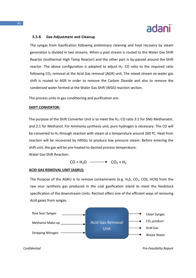
ACID GAS REMOVAL UNIT (AGRU):
The Purpose of the AGRU is to remove contaminants (e.g. H2S, CO2, COS, HCN) from the
raw sour synthesis gas produced in the coal gasification island to meet the feedstock
specification of the downstream Units. Rectisol offers one of the efficient ways of removing
Acid gases from syngas.
Raw Sour Syngas
Methanol Make-up
Stripping Nitrogen
Acid Gas Removal Unit
Clean Syngas
CO2 product
Acid Gas
Waste Water
Confidential Pre-Feasibility Report
44
RECTISOL:
Rectisol uses refrigerated methanol as the solvent for physical absorption of Acid gases & other
impurities present in Raw Syngas. Raw Syngas from the Shift Converter Unit, which is at 430 C is
cooled down to 70C by using spiral wound heat exchanger. Syngas containing impurities (trace
amount of NH3 & HCN), H2S and CO2 is fed to the Absorber Column. Rectisol unit removes H2S
and CO2 in one single absorption process and produces ultra-pure Syngas (total Sulphur <0.1
ppm (vol), CO2 <2 ppm (vol).
ABSORBER COLUMN
The Absorber Column has three section namely pre wash section, H2S absorption section and
CO2 absorption section.
The gas is then fed into the pre wash section of ABSORBER where trace components like NH3
and HCN are absorbed with a small stream of the sub cooled laden methanol coming from H2S
Absorber.
The gas is then routed via chimney into the H2S absorption section where H2S and COS are
scrubbed out with CO2 saturated methanol coming from the CO2 Absorption section. In this
section H2S is absorbed at around (-) 26 to (-) 38 0C. DeSulphurized Syngas then enters the
lower part of the CO2 Absorption section.
In the CO2 Absorption section the gas is washed with pure methanol (hot regenerated methanol
+ makeup methanol) at around (-) 44 to (-) 47 0C, pure methanol being fed to the top of the
Absorber.
Part of the methanol from CO2 absorber is routed to the top of the H2S Absorbing section while
the balance flows to the CO2 regenerator where it is flashed at the medium pressure removing
CO2.
The laden methanol from H2S Absorption section flows to the H2S Regenerator and the
recovered H2S will be further treated in the downstream Oxy-Claus Unit to recover elemental
Sulphur with purity over 99 %. This elemental Sulphur would be sold in the market for various
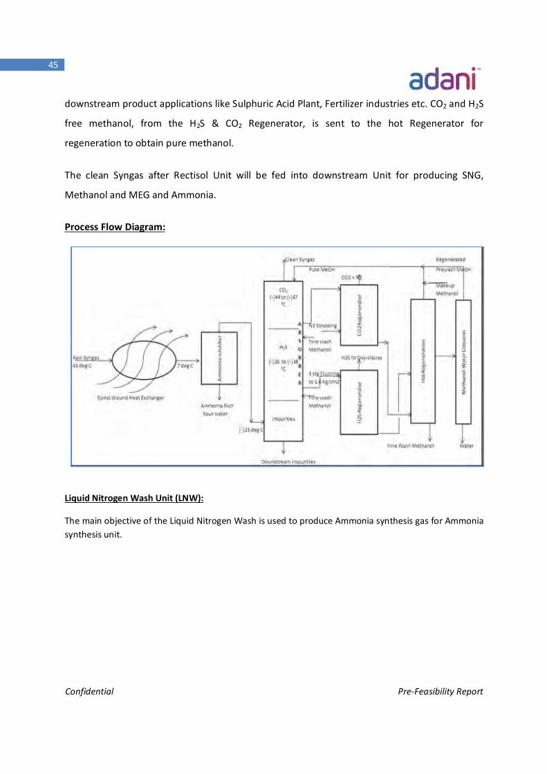
Confidential Pre-Feasibility Report
45
downstream product applications like Sulphuric Acid Plant, Fertilizer industries etc. CO2 and H2S
free methanol, from the H2S & CO2 Regenerator, is sent to the hot Regenerator for
regeneration to obtain pure methanol.
The clean Syngas after Rectisol Unit will be fed into downstream Unit for producing SNG,
Methanol and MEG and Ammonia.
Process Flow Diagram:
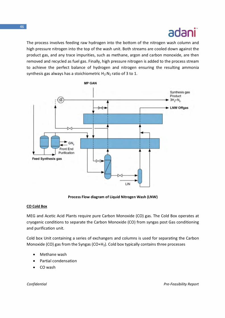
Liquid Nitrogen Wash Unit (LNW):
The main objective of the Liquid Nitrogen Wash is used to produce Ammonia synthesis gas for Ammonia synthesis unit.
Confidential Pre-Feasibility Report
46
The process involves feeding raw hydrogen into the bottom of the nitrogen wash column and high pressure nitrogen into the top of the wash unit. Both streams are cooled down against the product gas, and any trace impurities, such as methane, argon and carbon monoxide, are then removed and recycled as fuel gas. Finally, high pressure nitrogen is added to the process stream to achieve the perfect balance of hydrogen and nitrogen ensuring the resulting ammonia synthesis gas always has a stoichiometric H2:N2 ratio of 3 to 1.
Process Flow diagram of Liquid Nitrogen Wash (LNW)
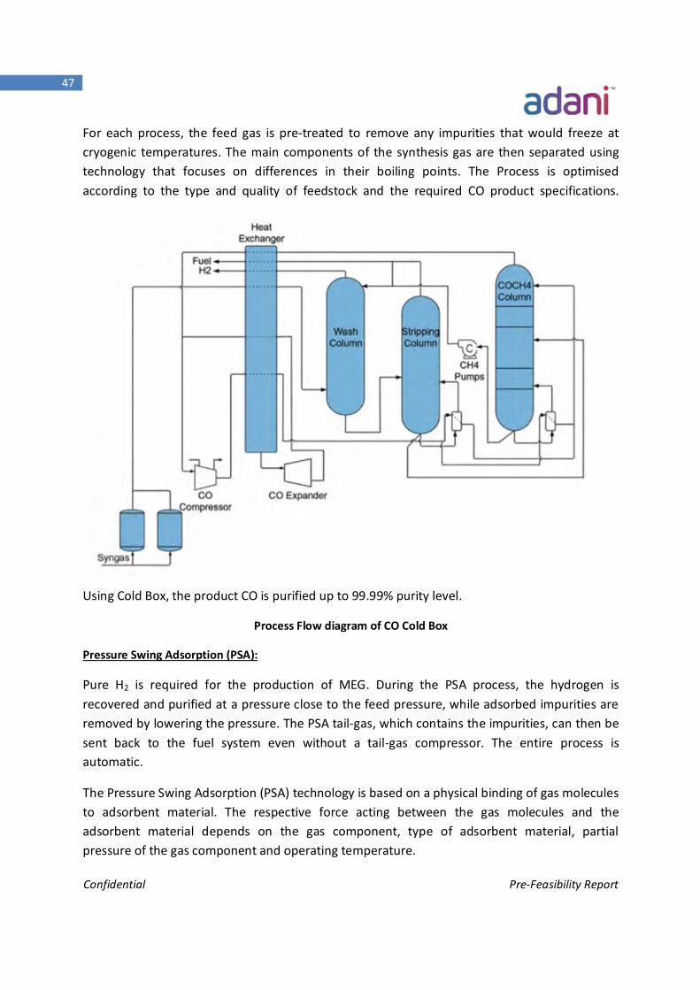
CO Cold Box
MEG and Acetic Acid Plants require pure Carbon Monoxide (CO) gas. The Cold Box operates at cryogenic conditions to separate the Carbon Monoxide (CO) from syngas post Gas conditioning and purification unit.
Cold box Unit containing a series of exchangers and columns is used for separating the Carbon Monoxide (CO) gas from the Syngas (CO+H2). Cold box typically contains three processes
Methane wash Partial condensation CO wash
Confidential Pre-Feasibility Report
47
For each process, the feed gas is pre-treated to remove any impurities that would freeze at cryogenic temperatures. The main components of the synthesis gas are then separated using technology that focuses on differences in their boiling points. The Process is optimised according to the type and quality of feedstock and the required CO product specifications.
Using Cold Box, the product CO is purified up to 99.99% purity level.
Process Flow diagram of CO Cold Box
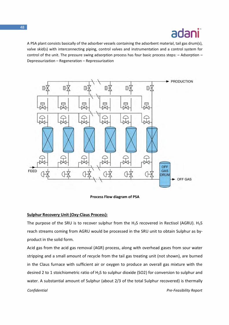
Pressure Swing Adsorption (PSA):
Pure H2 is required for the production of MEG. During the PSA process, the hydrogen is recovered and purified at a pressure close to the feed pressure, while adsorbed impurities are removed by lowering the pressure. The PSA tail-gas, which contains the impurities, can then be sent back to the fuel system even without a tail-gas compressor. The entire process is automatic.
The Pressure Swing Adsorption (PSA) technology is based on a physical binding of gas molecules to adsorbent material. The respective force acting between the gas molecules and the adsorbent material depends on the gas component, type of adsorbent material, partial pressure of the gas component and operating temperature.
Confidential Pre-Feasibility Report
48
A PSA plant consists basically of the adsorber vessels containing the adsorbent material, tail gas drum(s), valve skid(s) with interconnecting piping, control valves and instrumentation and a control system for control of the unit. The pressure swing adsorption process has four basic process steps: – Adsorption – Depressurization – Regeneration – Repressurization
Process Flow diagram of PSA
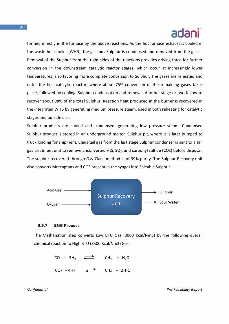
Sulphur Recovery Unit (Oxy-Claus Process):
The purpose of the SRU is to recover sulphur from the H2S recovered in Rectisol (AGRU). H2S
reach streams coming from AGRU would be processed in the SRU unit to obtain Sulphur as by-
product in the solid form.
Acid gas from the acid gas removal (AGR) process, along with overhead gases from sour water
stripping and a small amount of recycle from the tail gas treating unit (not shown), are burned
in the Claus furnace with sufficient air or oxygen to produce an overall gas mixture with the
desired 2 to 1 stoichiometric ratio of H2S to sulphur dioxide (SO2) for conversion to sulphur and
water. A substantial amount of Sulphur (about 2/3 of the total Sulphur recovered) is thermally
Confidential Pre-Feasibility Report
49
formed directly in the furnace by the above reactions. As the hot furnace exhaust is cooled in
the waste heat boiler (WHB), the gaseous Sulphur is condensed and removed from the gases.
Removal of the Sulphur from the right sides of the reactions provides driving force for further
conversion in the downstream catalytic reactor stages, which occur at increasingly lower
temperatures, also favoring more complete conversion to Sulphur. The gases are reheated and
enter the first catalytic reactor; where about 75% conversion of the remaining gases takes
place, followed by cooling, Sulphur condensation and removal. Another stage or two follow to
recover about 98% of the total Sulphur. Reaction heat produced in the burner is recovered in
the integrated WHB by generating medium pressure steam, used in both reheating for catalytic
stages and outside use.
Sulphur products are cooled and condensed, generating low pressure steam. Condensed
Sulphur product is stored in an underground molten Sulphur pit, where it is later pumped to
truck loading for shipment. Claus tail gas from the last stage Sulphur condenser is sent to a tail
gas treatment unit to remove unconverted H2S, SO2, and carbonyl sulfide (COS) before disposal.
The sulphur recovered through Oxy-Claus method is of 99% purity. The Sulphur Recovery unit
also converts Mercaptans and COS present in the syngas into Saleable Sulphur.
3.3.7 SNG Process
The Methanation step converts Low BTU Gas (3000 Kcal/Nm3) by the following overall
chemical reaction to High BTU (8500 Kcal/Nm3) Gas:
CO + 3H2 CH4 + H2O CO2 + 4H2 CH4 + 2H2O
Acid Gas
Oxygen
Sulphur Recovery Unit
Sulphur
Sour Water
Confidential Pre-Feasibility Report
50
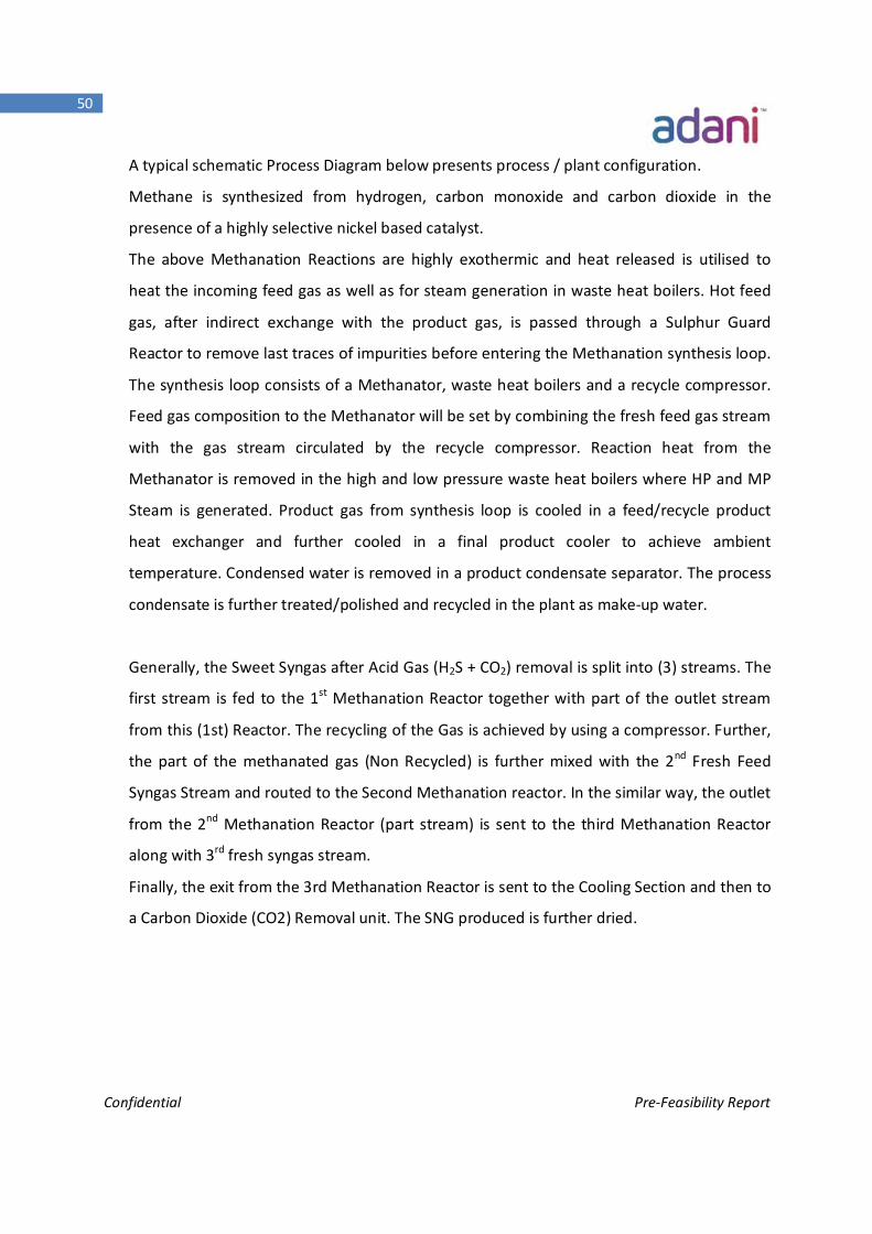
A typical schematic Process Diagram below presents process / plant configuration.
Methane is synthesized from hydrogen, carbon monoxide and carbon dioxide in the
presence of a highly selective nickel based catalyst.
The above Methanation Reactions are highly exothermic and heat released is utilised to
heat the incoming feed gas as well as for steam generation in waste heat boilers. Hot feed
gas, after indirect exchange with the product gas, is passed through a Sulphur Guard
Reactor to remove last traces of impurities before entering the Methanation synthesis loop.
The synthesis loop consists of a Methanator, waste heat boilers and a recycle compressor.
Feed gas composition to the Methanator will be set by combining the fresh feed gas stream
with the gas stream circulated by the recycle compressor. Reaction heat from the
Methanator is removed in the high and low pressure waste heat boilers where HP and MP
Steam is generated. Product gas from synthesis loop is cooled in a feed/recycle product
heat exchanger and further cooled in a final product cooler to achieve ambient
temperature. Condensed water is removed in a product condensate separator. The process
condensate is further treated/polished and recycled in the plant as make-up water.
Generally, the Sweet Syngas after Acid Gas (H2S + CO2) removal is split into (3) streams. The
first stream is fed to the 1st Methanation Reactor together with part of the outlet stream
from this (1st) Reactor. The recycling of the Gas is achieved by using a compressor. Further,
the part of the methanated gas (Non Recycled) is further mixed with the 2nd Fresh Feed
Syngas Stream and routed to the Second Methanation reactor. In the similar way, the outlet
from the 2nd Methanation Reactor (part stream) is sent to the third Methanation Reactor
along with 3rd fresh syngas stream.
Finally, the exit from the 3rd Methanation Reactor is sent to the Cooling Section and then to
a Carbon Dioxide (CO2) Removal unit. The SNG produced is further dried.
Confidential Pre-Feasibility Report
51
SNG Process Flow Diagram:
PRODUCT (SNG) GAS COMPRESSION AND DRYING
The product SNG from the Methanation section is further compressed by steam driven
centrifugal compressor from around 60 Bar to around 70-80 Bar depending upon on the
SNG pipeline pressure. Depending on the product SNG Gas condition and composition; the
SNG can be subjected for a dehydration step involving Molecular Sieve Adsorption/Drying.
This step may be suitably incorporated depending on the overall balance based on specific
technology/license.
Confidential Pre-Feasibility Report
52
3.3.8 Methanol Process
Methanol Synthesis:
Methanol is synthesized from hydrogen, carbon monoxide and carbon dioxide in the
presence of a highly selective copper based catalyst. The principal synthesis reactions are as
follows:
CO + 2H2 CH3 OH
CO2 + 3H2 CH3OH + H2O
These reactions are highly exothermic and the heat of reaction must be promptly removed
from its source. This is accomplished most effectively in the two stage methanol synthesis,
which consists of water- cooled and a gas- cooled methanol reactor system.
Preheated recycle gas and synthesis gas are mixed and routed to the gas cooled methanol
reactor. Passing the tube side, the feed gas is further heated up to the inlet temperature of
the water cooled methanol reactors, where the synthesis reactions take place in the
catalyst filled tubes.
The heat of reaction instantly is removed from the catalyst by partial evaporation of boiler
feed water, circulating between the reactor shell and the top mounted steam drum,
simultaneously generating steam.
The efficient heat removal from the reaction zone permits operation of the plant with a
very low recycle gas rate and still processing of high CO yields in the gas. A quasi-isothermal
condition is maintained in the system which ensures a high conversion rate, eliminating the
danger of catalyst overheating and keeping the formation of byproducts at an extremely
low level. This results in a very long service time of the methanol catalyst.
The relationship at saturation conditions of the steam / water mixture defines the boiling
water temperature by pressure control at the steam drum and maintains by this the exact
and constant temperature control in the catalyst filled tubes.
The medium pressure steam produced will be exported into the steam system of the overall
plant, to be used for process, heating or turbine drivers after superheating.
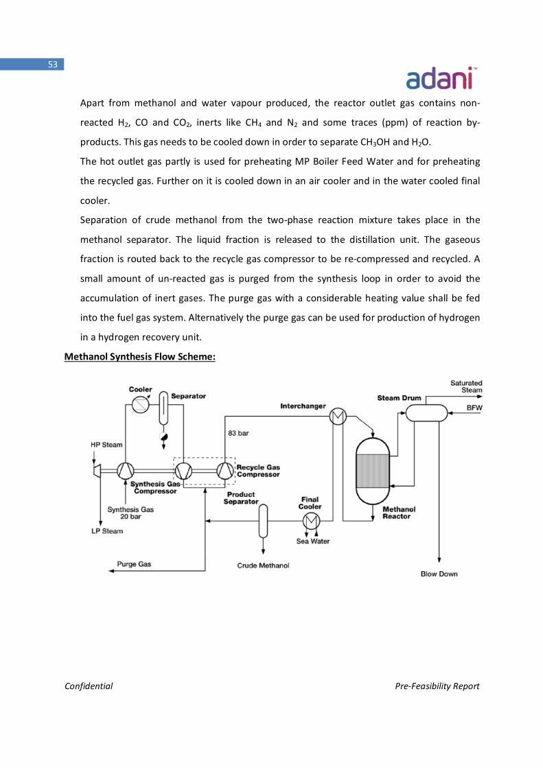
Confidential Pre-Feasibility Report
53
Apart from methanol and water vapour produced, the reactor outlet gas contains non-
reacted H2, CO and CO2, inerts like CH4 and N2 and some traces (ppm) of reaction by-
products. This gas needs to be cooled down in order to separate CH3OH and H2O.
The hot outlet gas partly is used for preheating MP Boiler Feed Water and for preheating
the recycled gas. Further on it is cooled down in an air cooler and in the water cooled final
cooler.
Separation of crude methanol from the two-phase reaction mixture takes place in the
methanol separator. The liquid fraction is released to the distillation unit. The gaseous
fraction is routed back to the recycle gas compressor to be re-compressed and recycled. A
small amount of un-reacted gas is purged from the synthesis loop in order to avoid the
accumulation of inert gases. The purge gas with a considerable heating value shall be fed
into the fuel gas system. Alternatively the purge gas can be used for production of hydrogen
in a hydrogen recovery unit.
Methanol Synthesis Flow Scheme:
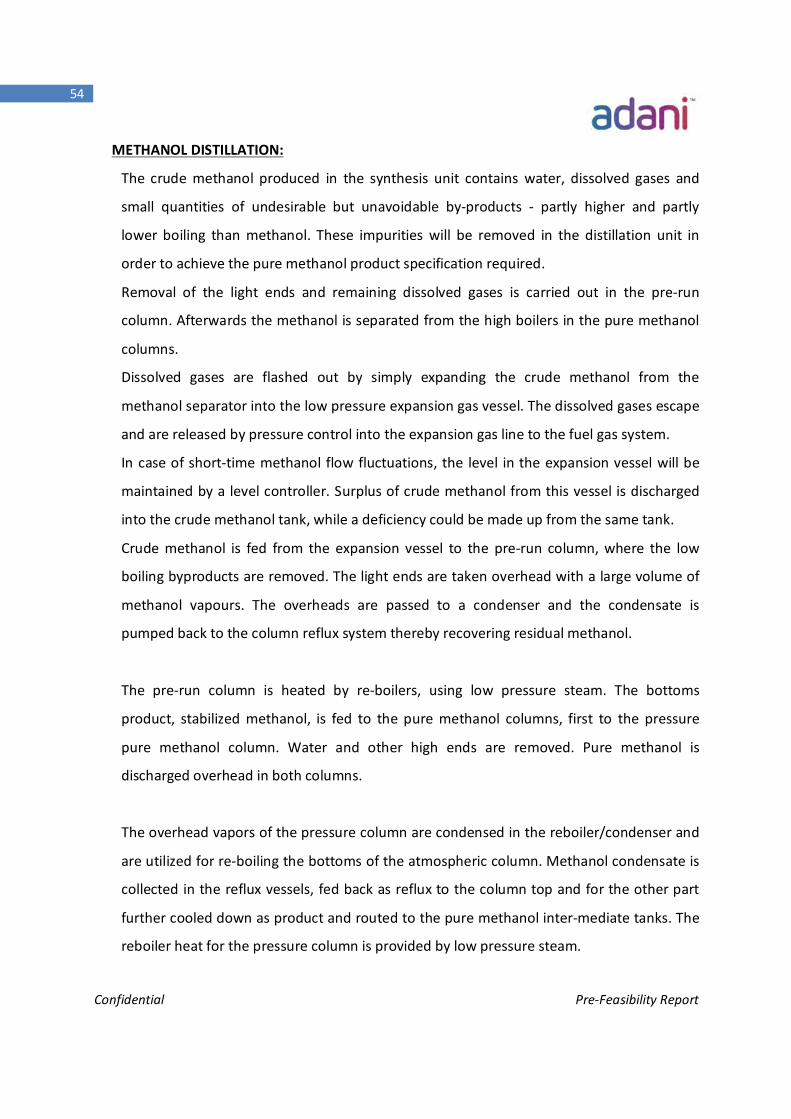
Confidential Pre-Feasibility Report
54
METHANOL DISTILLATION:
The crude methanol produced in the synthesis unit contains water, dissolved gases and
small quantities of undesirable but unavoidable by-products - partly higher and partly
lower boiling than methanol. These impurities will be removed in the distillation unit in
order to achieve the pure methanol product specification required.
Removal of the light ends and remaining dissolved gases is carried out in the pre-run
column. Afterwards the methanol is separated from the high boilers in the pure methanol
columns.
Dissolved gases are flashed out by simply expanding the crude methanol from the
methanol separator into the low pressure expansion gas vessel. The dissolved gases escape
and are released by pressure control into the expansion gas line to the fuel gas system.
In case of short-time methanol flow fluctuations, the level in the expansion vessel will be
maintained by a level controller. Surplus of crude methanol from this vessel is discharged
into the crude methanol tank, while a deficiency could be made up from the same tank.
Crude methanol is fed from the expansion vessel to the pre-run column, where the low
boiling byproducts are removed. The light ends are taken overhead with a large volume of
methanol vapours. The overheads are passed to a condenser and the condensate is
pumped back to the column reflux system thereby recovering residual methanol.
The pre-run column is heated by re-boilers, using low pressure steam. The bottoms
product, stabilized methanol, is fed to the pure methanol columns, first to the pressure
pure methanol column. Water and other high ends are removed. Pure methanol is
discharged overhead in both columns.
The overhead vapors of the pressure column are condensed in the reboiler/condenser and
are utilized for re-boiling the bottoms of the atmospheric column. Methanol condensate is
collected in the reflux vessels, fed back as reflux to the column top and for the other part
further cooled down as product and routed to the pure methanol inter-mediate tanks. The
reboiler heat for the pressure column is provided by low pressure steam.
Confidential Pre-Feasibility Report
55
The bottoms product of the Pressure Column containing the high ends is fed to the
atmospheric pure methanol column. Pure methanol is discharged overhead, condensed in
an air cooler and further cooled down. From the reflux vessel the product stream is routed
to the pure methanol intermediate tanks and the reflux pumped to the column top.
In order to reduce the contamination in the process water at the bottom of the
atmospheric column, the installation of a liquid side draw in the lower part of the
atmospheric column can be provided. The drawn liquid, mainly containing methanol and
high ends, can be vaporized and burnt together with fuel.
Low point drainage in the distillation is connected to the slop system. In case of repairs, the
relevant equipment can also be emptied into the slop vessel. The methanol from the slop
vessel is pumped to the crude methanol tank.
Methanol Distillation Flow Scheme:
Confidential Pre-Feasibility Report
56
3.3.9 Ammonia Synthesis
Compression
The synthesis gas from the battery limit is compressed to synthesis pressure in the
centrifugal type synthesis gas/recirculation compressor. The last stage serves also as the
recirculation Compressor and compresses the combined stream of make-up and recycles
gas.
Synthesis Loop
The mixture of make-up gas and recycle gas leaving recirculation compressor enters the hot
heat exchanger where the gas is heated to the converter inlet temperature by heat exchange
with the gas coming from the loop BFW preheater,
In the ammonia converter, the synthesis gas is reacted to an ammonia concentration of 19.6
mole%. The gas leaves the converter at a temperature of 468degC.
A considerable part of the heat content in the gas leaving the converter is recovered for
production of saturated steam at 44 barg in the loop waste heat boiler, Superheat steam to
385°C in steam super heater, and in the loop BFW preheater.
After the loop BFW preheater, the gas is cooled first in the hot heat exchanger mentioned
above, then in the water cooler, in which a substantial part of the ammonia is condensed.
The gas then passes the cold exchanger, in which it is cooled by heat exchange with the
recirculation gas coming from the ammonia separator. Finally, the gas is cooled in the
ammonia chillers and passed on to the ammonia separator in which the liquid ammonia is
separated.
The liquid ammonia from is depressurized to 25 barg in the let-down vessel and the liberated
gas is separated and returned to the suction side of the synthesis gas compressor, In order to
recover the hydrogen content in the gas. Afterwards, the liquid ammonia can be sent to two
locations.
Confidential Pre-Feasibility Report
57
In case ammonia storage, all ammonia is flashed-cooled to about -33°C in flash vessel, and
pumped to storage by means of the ammonia product pump. The small amounts of inert
gases entering the loop with the make-up synthesis gas will be released from the inert vent
gas separator. The off-gas is preheated in the off-gas heater, which is a coil in the ammonia
accumulator.
Ammonia Synthesis Converter
The ammonia synthesis converter is a Radial Flow Converter. It consists of a pressure shell
and a basket. The basket consists of three catalyst beds and two inter bed heat exchangers
placed in the center of the first and second catalyst bed respectively.
The main part of the synthesis gas is introduced into the converter through the inlet at the
bottom of the converter and passes upwards through the outer annulus between the basket
and the pressure shell, keeping the latter cooled. It then passes to the bottom tube sheet of
the first interbed heat exchanger through transfer pipes in the heat exchanger and passes
the tubes in upward direction thereby cooling the exit gas from the first bed to the inlet
temperature to second bed.
Another part of the synthesis gas is introduced through the bottom central inlet and flows
upwards through the transfer pipe to the bottom tube sheet of the second interbed heat
exchanger. It passes the tubes in upward direction thereby cooling the exit gas from the
second bed to the inlet temperature of the third bed.
The remaining part of the gas, the cold by-pass gas, is introduced at the top of the converter.
In the top of the converter pipe it mixes with the gas leaving the tube side of the two
interbed heat exchangers. The amount of cold by-pass gas controls the inlet temperature to
the first bed.
After mixing, the gas flows through the space below the basket cover to the annuli of the
panels around the first catalyst bed. From the panels it passes the first catalyst bed in inward
Confidential Pre-Feasibility Report
58
direction and then flows to the annulus between the first catalyst bed and the first interbed
heat exchanger. Even gas distribution in the catalyst bed is ensured by means of appropriate
perforation in the panels. The effluent from the first catalyst bed passes the shell side of the
first interbed heat exchanger for cooling to the proper inlet temperature to the second
catalyst bed by heat exchange with gas introduced through the tube side of the first interbed
heat exchanger as described above.
From the shell side of the first interbed heat exchanger the gas is transferred to the second
catalyst bed through the panels around the bed. The effluent from the second catalyst bed
passes the shell side of the second interbed heat exchanger for cooling to the proper inlet
temperature to the third catalyst bed by heat exchange with gas introduced to the tube side
of the second interbed heat exchanger through the bottom inlet as described above.
Both second catalyst and third catalyst beds are passed in inward direction, the gas
distribution being ensured by means of appropriate perforation at the walls of the bed.
The gas leaving the third catalyst bed passes the perforated center tube and flows to the
converter outlet.
Refrigeration Circuit
The purpose of the refrigeration circuit is to perform various cooling tasks including:
Condensation of produced ammonia in the synthesis loop
Condensation of ammonia in off gases
Cooling of liquid product to storage
The refrigeration circuit consists of the following main equipment:
The ammonia compressor
The ammonia condenser
The ammonia accumulator
A number of chillers
Three KO drums to protect against droplets of ammonia at the suction to the
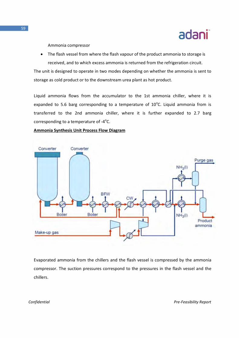
Confidential Pre-Feasibility Report
59
Ammonia compressor
The flash vessel from where the flash vapour of the product ammonia to storage is
received, and to which excess ammonia is returned from the refrigeration circuit.
The unit is designed to operate in two modes depending on whether the ammonia is sent to
storage as cold product or to the downstream urea plant as hot product.
Liquid ammonia flows from the accumulator to the 1st ammonia chiller, where it is
expanded to 5.6 barg corresponding to a temperature of 10oC. Liquid ammonia from is
transferred to the 2nd ammonia chiller, where it is further expanded to 2.7 barg
corresponding to a temperature of -4oC.
Ammonia Synthesis Unit Process Flow Diagram
Evaporated ammonia from the chillers and the flash vessel is compressed by the ammonia
compressor. The suction pressures correspond to the pressures in the flash vessel and the
chillers.
Confidential Pre-Feasibility Report
60
After compression, the ammonia is condensed in the ammonia condenser and collected in
the accumulator. Inert gases accumulating in the refrigeration system are vented from the
ammonia accumulator. Ammonia is condensed in the inert vent gas chiller and separated in
the inert vent gas separator. The off-gas from is heated and exported from the ammonia
plant.
3.3.10 Acetic Acid Process
Reaction Unit
Methanol and CO (3.4MPaG,ambient temperature) are sent to Boundary Layer of Acetic
Acid plant where CH3OH and CO are fed into continuous stirred reactor to form Acetic
Acid at 3 MPa pressure & 180~190℃temperature in presence of rhodium complex catalysts
& Iodide co-catalyst. The crude Acetic Acid product enters the distillation unit through a
flash vessel to recycle Liquid catalyst to reactor.
Un-reacted CO & inert gas at the top of the reactor and a small amount of H2, CO2 & CH4
which accompany production with Acetic Acid reaction are sent into a high pressure
adsorption unit through a high-pressure separator.
Distillation Unit
The gaseous crude Acetic Acid product from reaction unit is sent to pre-dissociation
column, to recover the entrained catalyst and to cycle it back to reactor. The gaseous crude
Acetic Acid product is sent to light component column where low boiling and light methyl
acetate & water and methyl iodide are removed at the column top, crude Acetic Acid is
recovered from the column bottom and sent to drying column to remove the water in
Acetic Acid and to get rid of trace iodine. Crude Acetic Acid at bottom of drying column
sends into product column to remove propionic acid and HI, Acetic Acid product of high
quality is achieved finally at top side of product column and bottoms contain Acetic Acid
and propionic acid. These are sent to stripper column where gaseous Acetic Acid is stripped
and circulated back to Acetic Acid product column. A small quantity liquid waste is sent to
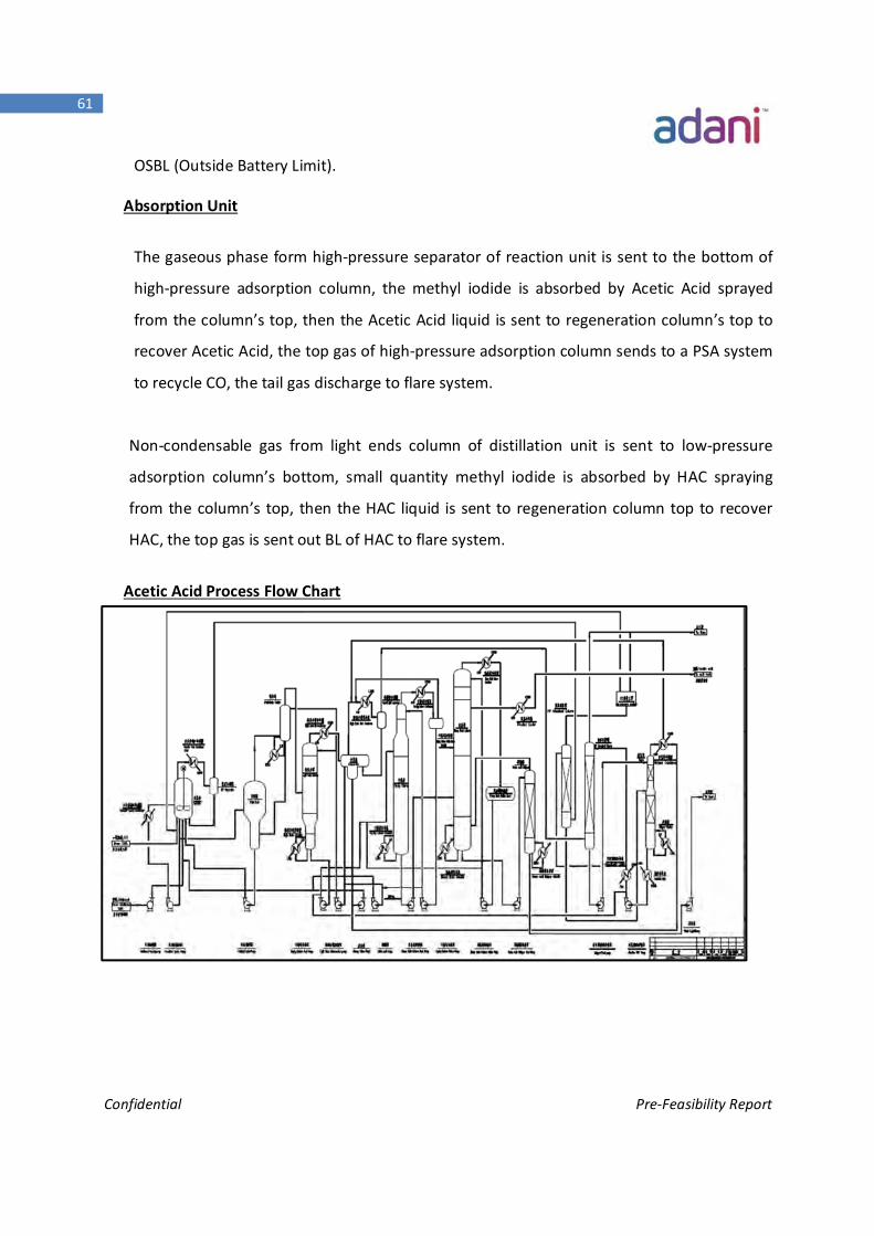
Confidential Pre-Feasibility Report
61
OSBL (Outside Battery Limit).
Absorption Unit
The gaseous phase form high-pressure separator of reaction unit is sent to the bottom of
high-pressure adsorption column, the methyl iodide is absorbed by Acetic Acid sprayed
from the column’s top, then the Acetic Acid liquid is sent to regeneration column’s top to
recover Acetic Acid, the top gas of high-pressure adsorption column sends to a PSA system
to recycle CO, the tail gas discharge to flare system.
Non-condensable gas from light ends column of distillation unit is sent to low-pressure
adsorption column’s bottom, small quantity methyl iodide is absorbed by HAC spraying
from the column’s top, then the HAC liquid is sent to regeneration column top to recover
HAC, the top gas is sent out BL of HAC to flare system.
Acetic Acid Process Flow Chart
Confidential Pre-Feasibility Report
62
3.3.11 MEG Block
The EG plant contains 5 units including esterification, Carbonylation, hydrogenation,
distillation and off gas disposal unit.
1. Esterification unit is that NO from Carbonylation unit and CH3OH from hydrogenation
unit take reactions to methyl nitrite (MN).
2. Carbonylation unit is that the feed stock CO and MN take coupled reaction to dimethyl
oxalate (DMO) intermediate product.
3. Hydrogenation unit is that DMO and H2 take reaction to crude EG product.
4. Distillation unit is a purification process to obtain superior EG and qualified EG
products.
5. Off-gas disposal unit is a catalytic reduction that makes the off gas from Carbonylation
and
Esterification units become to nitrogen, which can improve the plant control level of
environmental protection.
Esterification
The starting material of oxygen from outside battery limit will mix with the recycling gas
(including NO) in static mixer, subsequently taking place oxidation of NO into NO2 in the
following pre-oxidation reactor. Thus the recycling gas out from pre-oxidation reactor
mainly consists of N2, NO, NO2, MN, which goes to the bottom of esterification column to
produce MN via counter current contact with methanol Flowing from the top.
Principal reaction as follows:
2NO+O2→2NO2
NO+NO2+2CH4O→2CH3ONO+2H2O
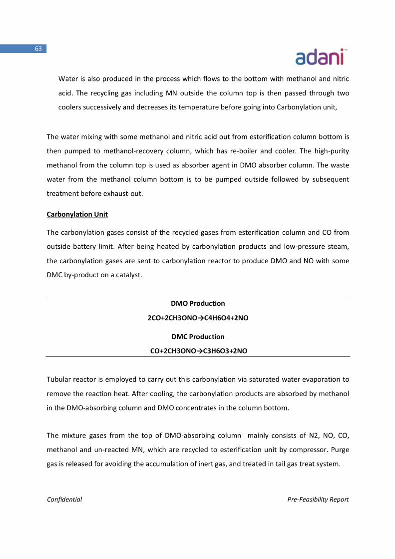
Confidential Pre-Feasibility Report
63
Water is also produced in the process which flows to the bottom with methanol and nitric
acid. The recycling gas including MN outside the column top is then passed through two
coolers successively and decreases its temperature before going into Carbonylation unit,
The water mixing with some methanol and nitric acid out from esterification column bottom is
then pumped to methanol-recovery column, which has re-boiler and cooler. The high-purity
methanol from the column top is used as absorber agent in DMO absorber column. The waste
water from the methanol column bottom is to be pumped outside followed by subsequent
treatment before exhaust-out.
Carbonylation Unit
The carbonylation gases consist of the recycled gases from esterification column and CO from
outside battery limit. After being heated by carbonylation products and low-pressure steam,
the carbonylation gases are sent to carbonylation reactor to produce DMO and NO with some
DMC by-product on a catalyst.
DMO Production
2CO+2CH3ONO→C4H6O4+2NO
DMC Production
CO+2CH3ONO→C3H6O3+2NO
Tubular reactor is employed to carry out this carbonylation via saturated water evaporation to
remove the reaction heat. After cooling, the carbonylation products are absorbed by methanol
in the DMO-absorbing column and DMO concentrates in the column bottom.
The mixture gases from the top of DMO-absorbing column mainly consists of N2, NO, CO,
methanol and un-reacted MN, which are recycled to esterification unit by compressor. Purge
gas is released for avoiding the accumulation of inert gas, and treated in tail gas treat system.
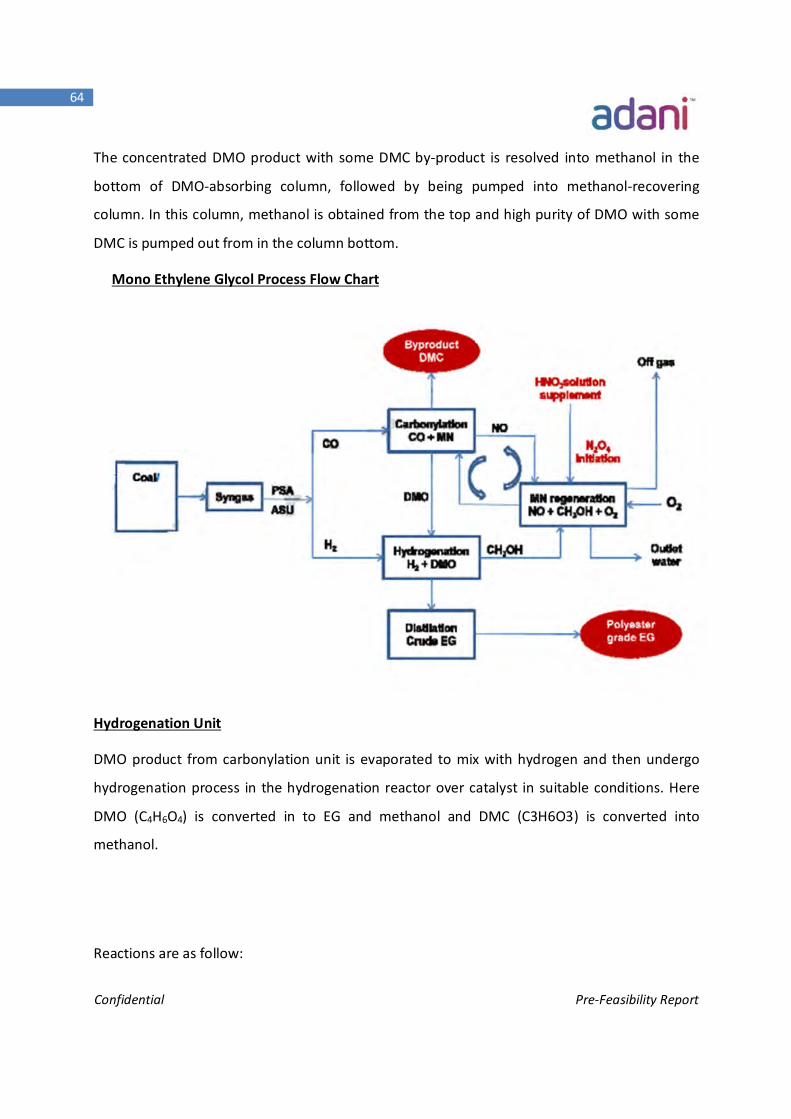
Confidential Pre-Feasibility Report
64
The concentrated DMO product with some DMC by-product is resolved into methanol in the
bottom of DMO-absorbing column, followed by being pumped into methanol-recovering
column. In this column, methanol is obtained from the top and high purity of DMO with some
DMC is pumped out from in the column bottom.
Mono Ethylene Glycol Process Flow Chart
Hydrogenation Unit
DMO product from carbonylation unit is evaporated to mix with hydrogen and then undergo
hydrogenation process in the hydrogenation reactor over catalyst in suitable conditions. Here
DMO (C4H6O4) is converted in to EG and methanol and DMC (C3H6O3) is converted into
methanol.
Reactions are as follow:
Confidential Pre-Feasibility Report
65
4H2+C4H6O4→C2H6O2+2CH4O
3H2+C3H6O3→3CH4O
Tubular reactor is employed for hydrogenation and saturated water is used to remove the
reaction heat by evaporation. After gas-liquid separation, hydrogen gas is recycled and mixed
with fresh hydrogen in OSBL for reuse, and the liquid is pumped into purification unit.
Purification unit
The hydrogenation liquid product of crude EG (Ethylene Glycol) is treated by removing
methanol, ethanol, water and then undergo distillation to produce polyester-grade EG product
and freezing-grade EG product.
3.3.12 MTO (Methanol to Olefins) Process:
Methanol produced from the Methanol plant along with steam is sent to a Fluidized catalytic
reactor (MTO Reactor) to produce range of olefins at high temperatures which is then sent to
downstream separator columns where Major products such as ethylene and propylene are
separated.
The MTO process majorly consists of three Blocks
1. Methanol reactor
2. Quenching , Caustic wash and Compression
3. Product separation
Methanol reactor
Methanol feed is sent to Methanol reactor where methanol is converted to Olefins in presence
of acidic Zeolite catalyst. The typical Propylene/Ethylene ratio in the product would be in the
range of 1.5-2. This ratio can be adjusted based on the product requirement.
Quench Caustic wash and Compression section
The High temperature MTO product gas produced is sent to quench section where the gas is
contacted with water in a quench tower to bring down the gas temperature before sending to
Confidential Pre-Feasibility Report
66
the caustic tower where acid gases produced in the reactor are removed using caustic solution.
The acid free gases from the top of caustic tower are sent to Main compressor to raise the gas
pressure that is necessary for downstream Separation columns.
Product separation
The product gases are sent to de-propaniser where C1-C3 cut is separated from the top of the
column and heaviers are collected at bottom of the column. The Lighter cut is sent Pre-cut oil
absorber unit and heavier cut containing C4+ is sent to dehexaniser.
The top product from the de-propaniser is compressed and sent to Pre-Cut & Oil Absorber
where the C1 cut is recovered from the top where as C2+ is collected from the bottom and sent
to De-ethaniser.
De-ethaniser column separates the feed gases in to C2 and C3 cuts collected at top and bottom
respectively. The C2 cut contains mainly ethylene, ethane and Acetylene. To meet the product
specification the gas is sent to acetylene convertor where the gases are reacted with Hydrogen
to convert acetylene to ethylene. These gases from the Acetylene reactor are sent to C2 Splitter
where ethylene and ethane are separated and then stored for further use.
The bottom product from the de-ethaniser (C3) is sent to the C3 splitter where propylene is
collected at the top and Propane is collected from the bottom.
The bottom cut from the De-Propaniser is sent to De-hexaniser to separate C4-C6 and C6+ cuts.
The products From the MTO plant are stored or sent to PE and PP plants to produce Poly-
Olefins plants.
3.3.13 Poly-ethylene Process
The process produces low density polyethylene and high density polyethylene using low
pressure in gas phase. Poly-ethylene is produced using proprietary solid or slurry catalyst. The
process produces wide range of polyethylene in a gas phase fluidized bed reactor using
proprietary solid and slurry catalyst. Gaseous ethylene, co monomer and catalyst are fed to
fluidized bed reactor containing fluidized bed of growing polymer particles operating at
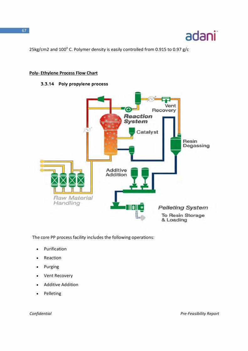
Confidential Pre-Feasibility Report
67
25kg/cm2 and 100o C. Polymer density is easily controlled from 0.915 to 0.97 g/c
Poly- Ethylene Process Flow Chart
3.3.14 Poly propylene process
The core PP process facility includes the following operations:
Purification
Reaction
Purging
Vent Recovery
Additive Addition
Pelleting
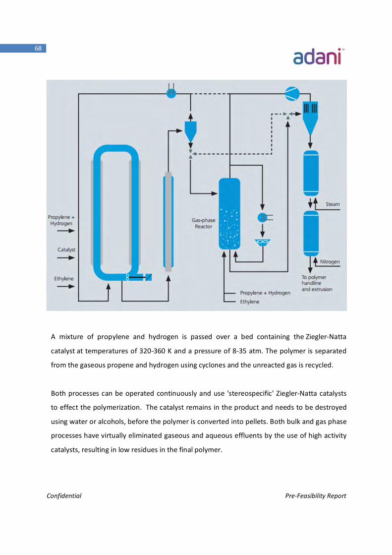
Confidential Pre-Feasibility Report
68
A mixture of propylene and hydrogen is passed over a bed containing the Ziegler-Natta
catalyst at temperatures of 320-360 K and a pressure of 8-35 atm. The polymer is separated
from the gaseous propene and hydrogen using cyclones and the unreacted gas is recycled.
Both processes can be operated continuously and use 'stereospecific' Ziegler-Natta catalysts
to effect the polymerization. The catalyst remains in the product and needs to be destroyed
using water or alcohols, before the polymer is converted into pellets. Both bulk and gas phase
processes have virtually eliminated gaseous and aqueous effluents by the use of high activity
catalysts, resulting in low residues in the final polymer.
Confidential Pre-Feasibility Report
69
3.3.15 Methanol to DME Production:
As an indirect method, dimethyl ether is produced by a process called the dehydration of
methanol over a solid-based acidic catalyst. One Water molecule is removed from every two
methanol molecules which results in the formation of DME. Regarding operations done, crude
methanol is fed to the stream then sent through a pump to series of heat exchangers to gain
the adequate temperature necessary for the reaction. Then reactants are fed to a fixed bed
reactor with a suitable catalyst to form dimethyl ether. Due to the exothermic nature of the
reaction, the effluent has to be cooled before separation of DME.
In the first distillation column, DME is separated, as a distillate, from other components.
Another distillation column is used to separate unreacted methanol (as the conversion is not
100%) and sent back as a fresh feed to the process through a recycle stream.
The main reaction in the dehydration process is:
2CH3OH CH3OCH3+H 2O
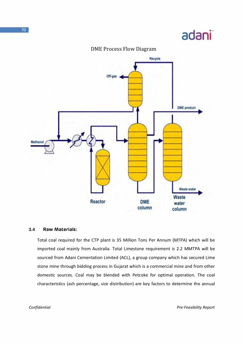
Confidential Pre-Feasibility Report
70
DME Process Flow Diagram
3.4 Raw Materials:
Total coal required for the CTP plant is 35 Million Tons Per Annum (MTPA) which will be
imported coal mainly from Australia. Total Limestone requirement is 2.2 MMTPA will be
sourced from Adani Cementation Limited (ACL), a group company which has secured Lime
stone mine through bidding process in Gujarat which is a commercial mine and from other
domestic sources. Coal may be blended with Petcoke for optimal operation. The coal
characteristics (ash percentage, size distribution) are key factors to determine the annual
Confidential Pre-Feasibility Report
71
tonnage required. The raw material required and its source along with the estimated
quantity is given below in the table:
Raw material Quantity Source
Coal 35 MMTPA Imported coal mainly from Australia
Limestone 2.2 MMTPA Domestic
As a facilitator, APSEZL would transport the coal received at Adani West Port to the factory gate
of the project through already approved utility corridor of APSEZL.
3.5 Utilities, Power Requirement & Offsite Units
Oxygen
Oxygen @ 92000 TPD (Tons per Day) at a purity level of 99% would be required. The
normal operating condition of oxygen is 45 bar gauge pressure and ambient temperature.
Steam:
Process boiler of 2X200 TPH is envisaged to cater for the initial steam requirement during
start-up activities of the plant
A part of the Steam generated through process will be used for internal consumption and
remaining Steam will be used for captive power production. This contains H.P Superheated,
H.P Saturated, M.P as well as L.P steam.
Plant / Instrument Air and Nitrogen:
The Plant / Instrument Air and Nitrogen System receives air and nitrogen from the Air
Separation Unit (ASU), and distributes these services to users, maintains an instrument air
reserve, and provides a back-up air supply to enable start-up of the ASU.
Fuel:
Confidential Pre-Feasibility Report
72
LNG (Liquefied Natural Gas)/ SNG produced from the plant would be utilized for any fuel
requirement of the CTP facility. LNG requirement for the complex is around 0.6 TPH. Other
Fuel storage facility required if any will be built as per requirement in accordance with
guidelines from Chief Controller of Explosives (CCOE).
Total estimated power requirement of the CTP project:
The total power requirement of the facility is 2600 MW. The By-product VHP, HP & MP
Steam which is produced from various process units of CTP plant would be used for the
power generation. Therefore part of the power requirement (around 600 MW) would be
met using Process Steam Turbine. Remaining power requirement would met by APSEZL.
The detail of Power Requirement Break-up is furnished in a tabular form in below Table:
Total Power Required : 2600 MW
Power Generation from Process Steam : 600 MW
Net imported power : 2000 MW
Water Requirement:
The Requirement of RO Water for the plant has been estimated as 400 Million Liters per
day (MLD). M/s. Adani Ports & Special Economic Zone Limited (APSEZL) will be supplying
the total water requirement for the plant. This RO water would be utilized to meet the DM
water make-up and Plant/Utility water requirement of CTP Complex. The water system is
highly integrated and is designed for Zero Liquid Discharge (ZLD).
DM Plant3
A dedicated DM plant will be set up to fulfill the requirement of BFW makeup and other
requirements.
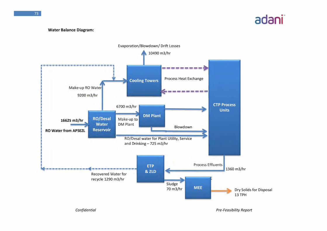
Confidential Pre-Feasibility Report
73
Water Balance Diagram:
RO Water from APSEZL
16625 m3/hr
9200 m3/hr
6700 m3/hr
1360 m3/hr ETP & ZLD
Cooling Towers
RO/Desal Water
Reservoir
Make-up RO Water
CTP Process Units
DM Plant Make-up to DM Plant
RO/Desal water for Plant Utility, Service and Drinking – 725 m3/hr
Process Heat Exchange
Evaporation/Blowdown/ Drift Losses
Process Effluents
Recovered Water for recycle 1290 m3/hr Sludge to MEE
10490 m3/hr
Blowdown
MEE Sludge 70 m3/hr Dry Solids for Disposal
13 TPH
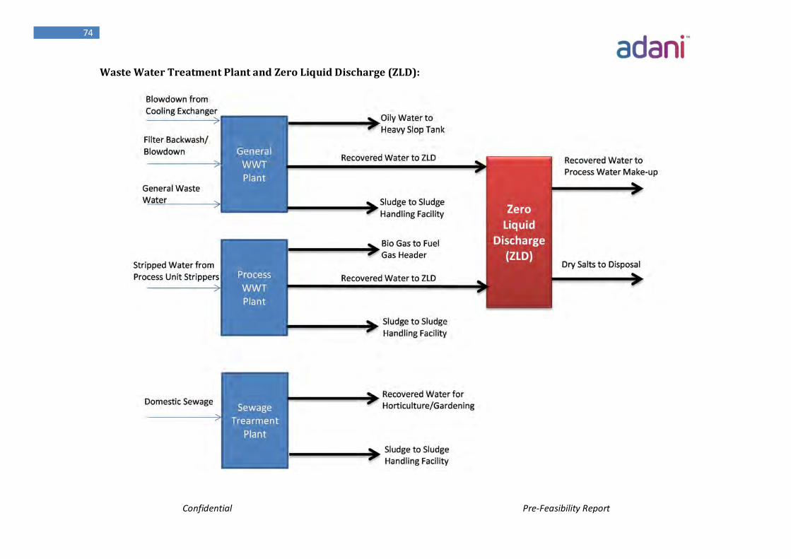
Confidential Pre-Feasibility Report
74
Waste Water Treatment Plant and Zero Liquid Discharge (ZLD):
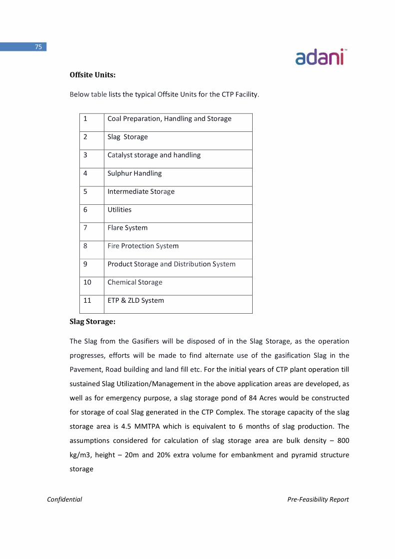
Confidential Pre-Feasibility Report
75
Offsite Units:
Below table lists the typical Offsite Units for the CTP Facility.
Slag Storage:
The Slag from the Gasifiers will be disposed of in the Slag Storage, as the operation
progresses, efforts will be made to find alternate use of the gasification Slag in the
Pavement, Road building and land fill etc. For the initial years of CTP plant operation till
sustained Slag Utilization/Management in the above application areas are developed, as
well as for emergency purpose, a slag storage pond of 84 Acres would be constructed
for storage of coal Slag generated in the CTP Complex. The storage capacity of the slag
storage area is 4.5 MMTPA which is equivalent to 6 months of slag production. The
assumptions considered for calculation of slag storage area are bulk density – 800
kg/m3, height – 20m and 20% extra volume for embankment and pyramid structure
storage
1 Coal Preparation, Handling and Storage
2 Slag Storage
3 Catalyst storage and handling
4 Sulphur Handling
5 Intermediate Storage
6 Utilities
7 Flare System
8 Fire Protection System
9 Product Storage and Distribution System
10 Chemical Storage
11 ETP & ZLD System
Confidential Pre-Feasibility Report
76
Sulphur Handling Unit:
The Sulphur Handling Unit will cool, solidify and package the hot liquid Sulphur from the
Sulphur Recovery Unit.
Intermediate Storage:
The Intermediate storage unit will:
• Act as a storage buffer for intermediate streams requiring rework within the plant
• Increase the availability and reliability of the facility
Utilities:
Soft Water, Cooling Water will be required for control of process as well as dissipation
of utilized heat. De-Mineralized Water will be required to generate Steam.
Plant Air & Instrument air after removal of moisture & passing through Dryer will be
used for various Process requirements. Nitrogen will be required in Coal feeder and for
purging also.
Flare System:
The CTP facility will be provided with a flare system in order to dispose of unrecoverable
hydrocarbon or contaminated gas streams from the process. Three individual flare
services are anticipated for the plant. A syngas flare to handle releases from the syngas
purification systems, a sour gas flare - servicing mainly low pressure vapor releases
containing H2S and NH3, and an NH3 flare to handle emergency releases from the
Refrigeration system. These gas streams may originate from pressure control and relief
systems used to prevent overpressure situations during normal operation, pressure
control during start-up and shutdown scenarios and also for the safe disposal of relief
gasses that may be vented during abnormal conditions, e.g. plant trips.
Confidential Pre-Feasibility Report
77
Fire Protection System:
The CTP facility will be provided with a fire protection system to cater for any potential
firefighting requirements. The primary supply of fire water will be stored onsite. A
secondary supply of fire water is usually obtained from offsite.
Final Storage and Product Distribution System:
The final product Storage and Distribution System's duty is to store and distribute the
primary products from the CTP facility as well as the by-products from gasification.
Chemical Storage:
The CTP process uses a number of catalysts and chemicals during operation. These
catalysts and chemicals can be broken down into several different groups as follows:
Catalysts that promote a desired chemical reaction, such as product hydro
treating
Regenerable adsorption beds, such as ion exchange resins
Non-regenerable adsorption beds, such as activated carbon
Pre-coat and filter aid for filtration
Continuous use reagents, such as sodium hydroxide (NaOH) chemicals
Intermittent use reagents, such as ion exchange resin regeneration reagents
The Chemical Storage area houses any spare or standby catalyst and
chemicals.
ETP & ZLD:
The process waste water generated from the plant would be treated suitably using
biological & chemical Effluent Treatment Plant, Tertiary Treatment Plant and reuse the
waste water within the process. To handle the reject brine from Tertiary Treatment
Plant, Multiple Effective Evaporator (MEE) shall be installed and Zero Liquid Discharge
(ZLD) shall be achieved. Dry sludge/salts from MEE (around 13 TPH) shall be disposed
Confidential Pre-Feasibility Report
78
through authorized agencies as per Hazardous Waste Management (HWM) Rule.
Domestic wastewater will be treated in Sewage Treatment Plant and the treated water
would be utilized for Horticulture purposes.
3.6 Automation, Control and Business Systems:
3.6.1 Distributed Control System
The Distributed Control System (DCS) will provide process control and monitoring for
the CTP Facility. At the process control level it will perform basic regulatory and
sequential control, non-safety related interlocks, process monitoring, alarm
management, data archiving, reporting, etc. The DCS will be capable of performing
higher level functions such as advanced control, equipment health monitoring, process
optimization, interface to company network, advanced alarm management, etc.
The DCS will provide the primary operating window to the operating plant and will be
interfaced with other major instrument subsystems such as Fire & Gas, Safety
Instrumented System (SIS), package control systems, etc. Basic functionality will
include but not be limited to:
Plant monitoring and control for start-up, normal operation, and shutdown
operations
Functions for instrument set-up, diagnostics and testing for the DCS, SIS and
Fire and Gas Detection System (FGS)
Alarm Management: The DCS will have alarm logging and management
capabilities.
Trending in both real-tune and historical
The DCS will provide reports to support operational, maintenance and
management needs. These will be available on demand or printed
automatically at specific intervals.
Historisation of selected variables
Communication to new and existing facilities as required.
Confidential Pre-Feasibility Report
79
On-line diagnostics of the control system hardware
Ability to communicate with field devices
Workstation(s) for engineer level access to configuration and programming
functions of the DCS system.
Asset Management Systems
Integration with the company's information network for reel-time historical
data access
3.6.2 Safety Instrumented Systems
The CTP Facility will be provided with a dedicated SIS. The SIS system solves logic based
on input-upset conditions and shuts down specific equipment or areas of the plant in a
safe and predetermined manner. The SIS system hardware will be separate from all
other control systems and will not require the correct operation of any other system to
fulfill its own shutdown functions.
The SIS system will be designed in accordance with an industry standard (ISA S84.01 or
equivalent). Safety Integrity assessments will be performed to assign Safety Integrity
Levels (SILs) to shutdown loops.
The SIS will contain the following functions:
All manual Emergency Shutdown (ESD) pushbuttons for entire plant, units and
individual equipment
All safety related and equipment protection shutdown functions, as well as
environmental protection functions, rated SIL 1-3
Shutdown functions with SIL 4 or higher ratings e.g. High Integrity Protection
Systems (HIPS) will be evaluated on an individual basis
The operator interface to the SIS system will be the DCS operator consoles. All alarms
and status indications will be displayed on the DCS screens. On a case-by-case basis
selected alarms may be annunciated on a local or remote annunciator panel. Manual
shutdown buttons shall be provided on panels within each operator console and in the
field.
Confidential Pre-Feasibility Report
80
The status of all inputs and outputs of the SIS system shall be monitored by a Sequence
of Events Recorder (SER). It shall record all changes in status with sufficient resolution
to allow determination of the first-out event.
3.6.3 Fire and Gas Detection System:
The overall facilities and associated buildings will be provided with FGS to provide early
warning of a fire or gas leak situation. The FGS shall be separate from all other control
systems, and shall not require the correct operation of any other system to fulfill its own
functions.
3.6.4 Business Information Systems:
A management information System (MIS) and an Enterprise Resource Planning system
(ERP) will be seamlessly integrated into the plant control network to ensure effective
business processes and appropriate management reporting.
3.7 Health, Safety and Environment:
The following section provides a summary of EHS issues associated with coal processing
projects, along with recommendations for their management. The CTP facility will strive
for ISO (international organization for standardization) 14001 and OHSAS (occupational
health & safety management system) 18001 certification. The ISO 14001 standard is an
internationally accepted standard for the development and implementation of
environmental management systems, while OHSAS 18001 is an international
occupational health and safety management system.
3.7.1 Environmental issues
Potential environmental issues associated with coal processing projects include:
Air emissions
Waste Water
Solid waste management.
Noise
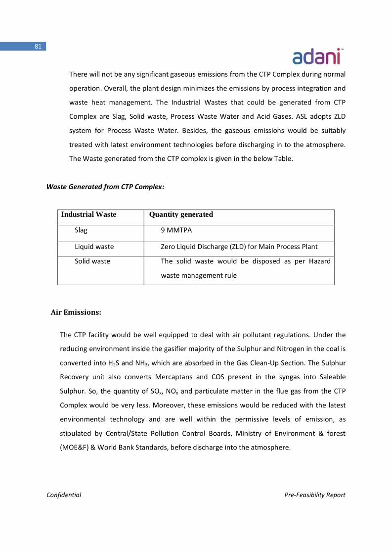
Confidential Pre-Feasibility Report
81
There will not be any significant gaseous emissions from the CTP Complex during normal
operation. Overall, the plant design minimizes the emissions by process integration and
waste heat management. The Industrial Wastes that could be generated from CTP
Complex are Slag, Solid waste, Process Waste Water and Acid Gases. ASL adopts ZLD
system for Process Waste Water. Besides, the gaseous emissions would be suitably
treated with latest environment technologies before discharging in to the atmosphere.
The Waste generated from the CTP complex is given in the below Table.
Waste Generated from CTP Complex:
Air Emissions:
The CTP facility would be well equipped to deal with air pollutant regulations. Under the
reducing environment inside the gasifier majority of the Sulphur and Nitrogen in the coal is
converted into H2S and NH3, which are absorbed in the Gas Clean-Up Section. The Sulphur
Recovery unit also converts Mercaptans and COS present in the syngas into Saleable
Sulphur. So, the quantity of SOx, NOx and particulate matter in the flue gas from the CTP
Complex would be very less. Moreover, these emissions would be reduced with the latest
environmental technology and are well within the permissive levels of emission, as
stipulated by Central/State Pollution Control Boards, Ministry of Environment & forest
(MOE&F) & World Bank Standards, before discharge into the atmosphere.
Industrial Waste Quantity generated
Slag 9 MMTPA
Liquid waste Zero Liquid Discharge (ZLD) for Main Process Plant
Solid waste The solid waste would be disposed as per Hazard
waste management rule
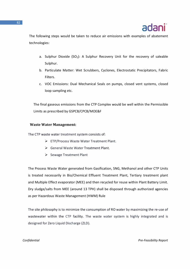
Confidential Pre-Feasibility Report
82
The following steps would be taken to reduce air emissions with examples of abatement
technologies:
a. Sulphur Dioxide (SO2): A Sulphur Recovery Unit for the recovery of saleable
Sulphur.
b. Particulate Matter: Wet Scrubbers, Cyclones, Electrostatic Precipitators, Fabric
Filters.
c. VOC Emissions: Dual Mechanical Seals on pumps, closed vent systems, closed
loop sampling etc.
The final gaseous emissions from the CTP Complex would be well within the Permissible
Limits as prescribed by GSPCB/CPCB/MOE&F
Waste Water Management:
The CTP waste water treatment system consists of:
ETP/Process Waste Water Treatment Plant.
General Waste Water Treatment Plant.
Sewage Treatment Plant
The Process Waste Water generated from Gasification, SNG, Methanol and other CTP Units
is treated necessarily in Bio/Chemical Effluent Treatment Plant, Tertiary treatment plant
and Multiple Effect evaporator (MEE) and then recycled for reuse within Plant Battery Limit.
Dry sludge/salts from MEE (around 13 TPH) shall be disposed through authorized agencies
as per Hazardous Waste Management (HWM) Rule
The site philosophy is to minimize the consumption of RO water by maximizing the re-use of
wastewater within the CTP facility. The waste water system is highly integrated and is
designed for Zero Liquid Discharge (ZLD).

Confidential Pre-Feasibility Report
83
The generated sewage waste water would be treated in Sewage Treatment Plant and the
treated water would be utilized for Horticulture purposes.
Solid Waste Management:
The main solid waste from the Plant is the Slag from the Gasification Island. The total
amount of Slag generated from the Gasification Island is about 9 MMTPA. Slag generated
out of Gasification Island is non Leachable, non-hazardous and easily passes the
regulatory limits for metals and organics and standard waste characteristic tests for
toxicity, reactivity, ignitibility, and corrosiveness.
ASL would seriously look into to maximize the utilization of coal in the following areas:
1. Road/ Embankment Making
2. Land development
3. Cement Making
4. Mine Backfilling
5. Synthetic Light weight Aggregate production
Of these, a number of applications were tested and tried and found to be suitable for high
volume applications. In particular, the utilization of slag in applications such as road and
construction aggregates, cement additives, and lightweight aggregates has been
demonstrated successfully
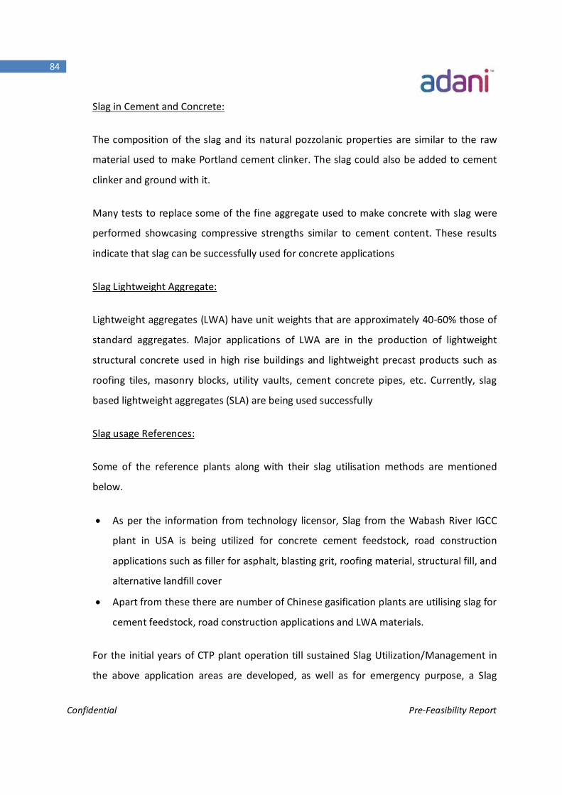
Confidential Pre-Feasibility Report
84
Slag in Cement and Concrete:
The composition of the slag and its natural pozzolanic properties are similar to the raw
material used to make Portland cement clinker. The slag could also be added to cement
clinker and ground with it.
Many tests to replace some of the fine aggregate used to make concrete with slag were
performed showcasing compressive strengths similar to cement content. These results
indicate that slag can be successfully used for concrete applications
Slag Lightweight Aggregate:
Lightweight aggregates (LWA) have unit weights that are approximately 40-60% those of
standard aggregates. Major applications of LWA are in the production of lightweight
structural concrete used in high rise buildings and lightweight precast products such as
roofing tiles, masonry blocks, utility vaults, cement concrete pipes, etc. Currently, slag
based lightweight aggregates (SLA) are being used successfully
Slag usage References:
Some of the reference plants along with their slag utilisation methods are mentioned
below.
As per the information from technology licensor, Slag from the Wabash River IGCC
plant in USA is being utilized for concrete cement feedstock, road construction
applications such as filler for asphalt, blasting grit, roofing material, structural fill, and
alternative landfill cover
Apart from these there are number of Chinese gasification plants are utilising slag for
cement feedstock, road construction applications and LWA materials.
For the initial years of CTP plant operation till sustained Slag Utilization/Management in
the above application areas are developed, as well as for emergency purpose, a Slag
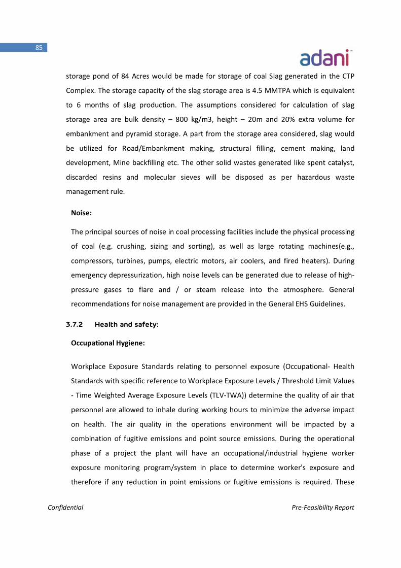
Confidential Pre-Feasibility Report
85
storage pond of 84 Acres would be made for storage of coal Slag generated in the CTP
Complex. The storage capacity of the slag storage area is 4.5 MMTPA which is equivalent
to 6 months of slag production. The assumptions considered for calculation of slag
storage area are bulk density – 800 kg/m3, height – 20m and 20% extra volume for
embankment and pyramid storage. A part from the storage area considered, slag would
be utilized for Road/Embankment making, structural filling, cement making, land
development, Mine backfilling etc. The other solid wastes generated like spent catalyst,
discarded resins and molecular sieves will be disposed as per hazardous waste
management rule.
Noise:
The principal sources of noise in coal processing facilities include the physical processing
of coal (e.g. crushing, sizing and sorting), as well as large rotating machines(e.g.,
compressors, turbines, pumps, electric motors, air coolers, and fired heaters). During
emergency depressurization, high noise levels can be generated due to release of high-
pressure gases to flare and / or steam release into the atmosphere. General
recommendations for noise management are provided in the General EHS Guidelines.
3.7.2 Health and safety:
Occupational Hygiene:
Workplace Exposure Standards relating to personnel exposure (Occupational- Health
Standards with specific reference to Workplace Exposure Levels / Threshold Limit Values
- Time Weighted Average Exposure Levels (TLV-TWA)) determine the quality of air that
personnel are allowed to inhale during working hours to minimize the adverse impact
on health. The air quality in the operations environment will be impacted by a
combination of fugitive emissions and point source emissions. During the operational
phase of a project the plant will have an occupational/industrial hygiene worker
exposure monitoring program/system in place to determine worker's exposure and
therefore if any reduction in point emissions or fugitive emissions is required. These
Confidential Pre-Feasibility Report
86
programs are risk based and only implemented once a final health risk assessment of
the new plant is conducted.
Fugitive emissions will be governed by a leak Detection and Repair (LDAR) program. An
LDAR program provides regular monitoring and detection of leaks on pipes, equipment,
valve stems, rotating equipment etc. It specifies when leaks should be repaired, the use
of specific equipment to minimize leaks or specified work practices. In addition the
nature of the chemical as per occupational hygiene and inherent safety requirements
will also determine the extent of modifications required to a piece of equipment. The
CTP facility will develop a LDAR program according to the US EPA standards.
Community Health
The guiding principle of Pollution Prevention is that a precautionary, rather than a
curative, approach should be followed i.e. "prevention is better than the cure". The HSE
(Health, Safety and Environment) design philosophies focuses on the manner in which
design facilities will be designed considering the protection of human health, safety and
the environment. The ASL HSE and Sustainable Development strategy aims to support
ASL's right to sell its products and to operate its plants and to build new facilities.
Sustainable Development at ASL will be carried out on the framework of its Values, Code
of Ethics and HSE Policy.
Confidential Pre-Feasibility Report
87
Chapter -4 Site Analysis
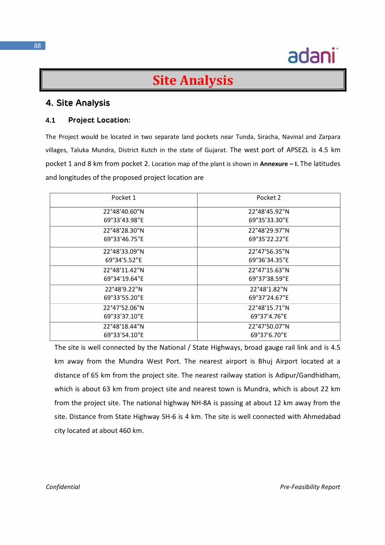
Confidential Pre-Feasibility Report
88
Site Analysis 4. Site Analysis
4.1 Project Location:
The Project would be located in two separate land pockets near Tunda, Siracha, Navinal and Zarpara
villages, Taluka Mundra, District Kutch in the state of Gujarat. The west port of APSEZL is 4.5 km
pocket 1 and 8 km from pocket 2. Location map of the plant is shown in Annexure – I. The latitudes
and longitudes of the proposed project location are
Pocket 1 Pocket 2
22°48'40.60"N 69°33'43.98"E
22°48'45.92"N 69°35'33.30"E
22°48'28.30"N 69°33'46.75"E
22°48'29.97"N 69°35'22.22"E
22°48'33.09"N 69°34'5.52"E
22°47'56.35"N 69°36'34.35"E
22°48'11.42"N 69°34'19.64"E
22°47'15.63"N 69°37'38.59"E
22°48'9.22"N 69°33'55.20"E
22°48'1.82"N 69°37'24.67"E
22°47'52.06"N 69°33'37.10"E
22°48'15.71"N 69°37'4.76"E
22°48'18.44"N 69°33'54.10"E
22°47'50.07"N 69°37'6.70"E
The site is well connected by the National / State Highways, broad gauge rail link and is 4.5
km away from the Mundra West Port. The nearest airport is Bhuj Airport located at a
distance of 65 km from the project site. The nearest railway station is Adipur/Gandhidham,
which is about 63 km from project site and nearest town is Mundra, which is about 22 km
from the project site. The national highway NH-8A is passing at about 12 km away from the
site. Distance from State Highway SH-6 is 4 km. The site is well connected with Ahmedabad
city located at about 460 km.
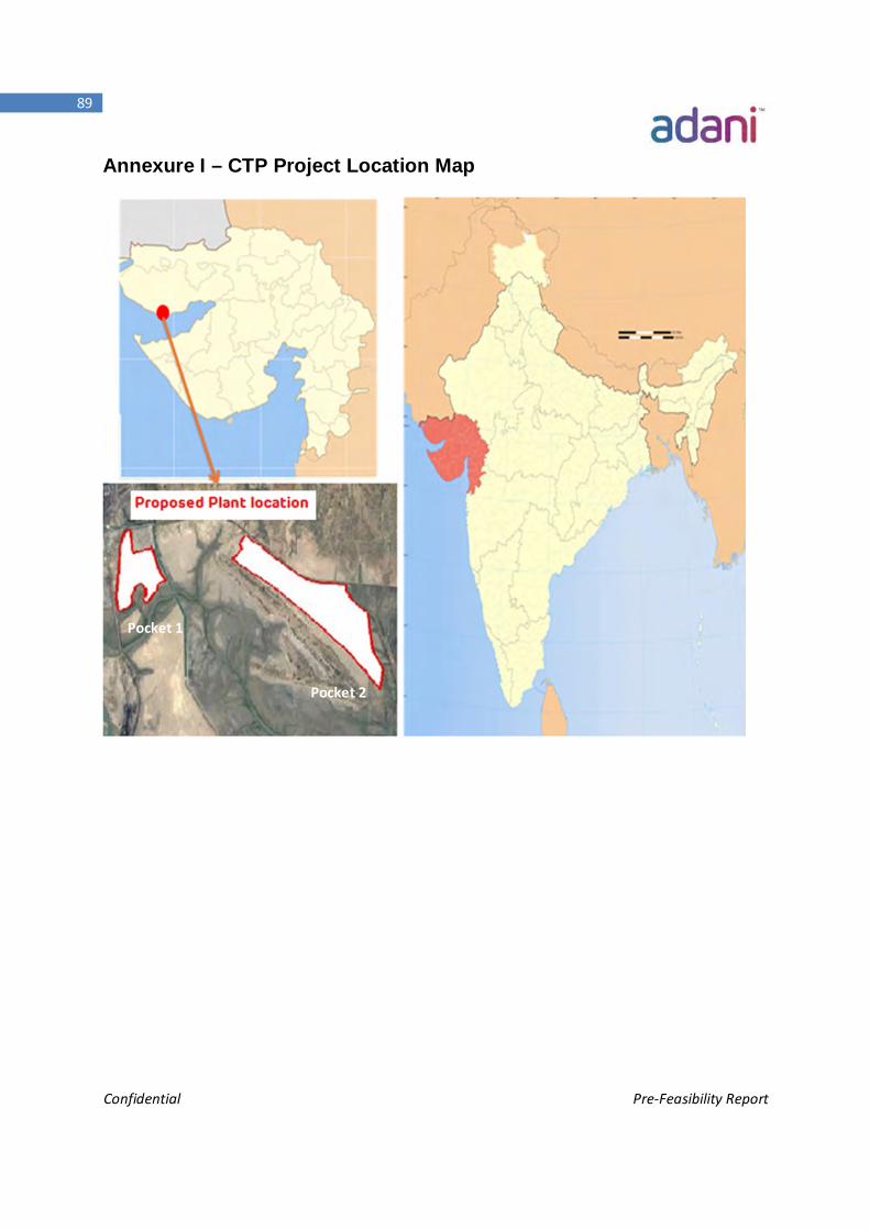
Confidential Pre-Feasibility Report
89
Annexure I – CTP Project Location Map
Pocket 1
Pocket 2
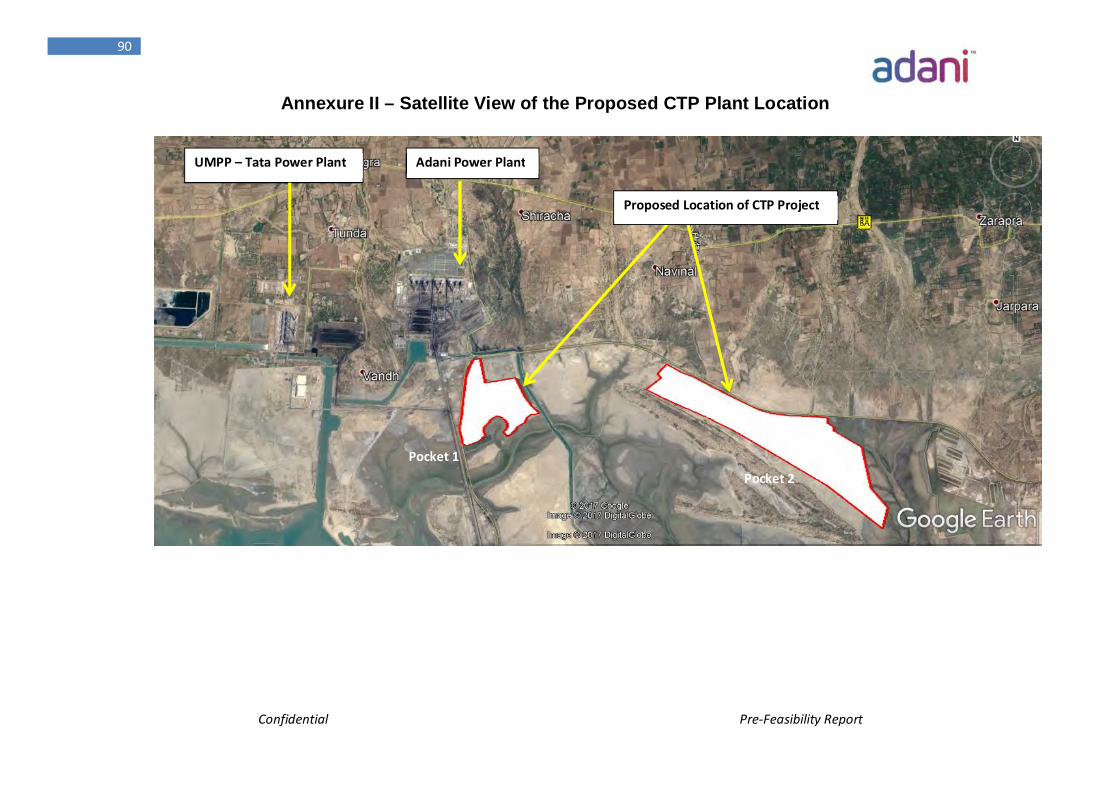
Confidential Pre-Feasibility Report
90
Annexure II – Satellite View of the Proposed CTP Plant Location
Adani Power Plant UMPP – Tata Power Plant
Proposed Location of CTP Project
Pocket 1 Pocket 2
Confidential Pre-Feasibility Report
91
4.1.1 Connectivity:
The Project would be located in two separate pockets near Tunda, Siracha, Navinal
and Zarpara villages, Taluka Mundra, District Kutch in the state of Gujarat. The west
port is 4.5 km from Pocket 1 and 8.5 km from pocket 2. The latitudes and longitudes of
the proposed project location are
Pocket 1 Pocket 2
22°48'40.60"N 69°33'43.98"E
22°48'45.92"N 69°35'33.30"E
22°48'28.30"N 69°33'46.75"E
22°48'29.97"N 69°35'22.22"E
22°48'33.09"N 69°34'5.52"E
22°47'56.35"N 69°36'34.35"E
22°48'11.42"N 69°34'19.64"E
22°47'15.63"N 69°37'38.59"E
22°48'9.22"N 69°33'55.20"E
22°48'1.82"N 69°37'24.67"E
22°47'52.06"N 69°33'37.10"E
22°48'15.71"N 69°37'4.76"E
22°48'18.44"N 69°33'54.10"E
22°47'50.07"N 69°37'6.70"E
As the project land is in two pockets, Syngas produced from pocket 1 would be
transported to the pocket 2 through the syngas pipeline to produce downstream
chemicals. The plant is located at 0.1 KM from APL Road. The proposed syngas
pipeline from pocket 1 to pocket 2 will be laid in the existing approved utility
corridor of APSEZL along the existing road as shown in the layout map. The
connecting syngas pipeline between the land pockets is under the scope of APSEZL.
Nearest airport is at Bhuj which is around 60 Km from the site. Kandla Airport is
around 65 km away from the proposed site. The nearest railway station is
Adipur/Gandhidham, which is 63 km from site.
4.1.2 Land Form/land Use Pattern, Use & Ownership:
The area earmarked for proposed CTP complex is owned by APSEZL and free from
any human activities. Rehabilitation & Resettlement measures are not necessary as
there is no Inhabitation in the earmarked area. Around 948.5 Ac. land would be
required for entire CTP complex including its Greenbelt (33% of total land). The
Confidential Pre-Feasibility Report
92
identified land is not an agricultural land but already designated/recorded as
industrial land. Land for different corridors (Power/Road/Coal Conveyor/Product
transfer pipelines) would be additional.
Sr,No. Particulars Approx. Area in Acres
Current Ownership
1 Pocket-1 265.86 Acres APSEZL
2 Pocket-2 682.61 Acres APSEZL
Total 948.5 Acres
4.1.3 Topography:
The project site is located within the APSEZL land. Hence, there is no significant
vegetation or habitation in the project site.
The existing nearby industries are 4000 MW Coastal Gujarat Power Plant owned by
Tata Power (north west side of project area), 4620 MW Adani Power Limited (North
direction from the project) and West Port of APSEZL (South direction from project).
The villages which are in close proximity to the project site are Siracha,Navinal,
Tunda and Zarpara.
Detailed Land Use / Land cover study will also be carried out as part of study.
4.1.4 Existing Infrastructure:
Distance from Mundra Town – 22 KM
Distance from Mundra West Port – 4.5 KM
Distance from State Highway-6 – 4 KM (Gandhidham-Mundra-Mandvi)
Distance from NH8A – 12 KM
Distance from Railway line – 3.2 KM (APL Gate no-4)
Distance from Adani Airstrip – 25 KM
Distance from Commercial Airport (Bhuj) – 60 KM
Distance from Commercial Airport (Kandla) – 65 KM
Water source (Sea) – Adjacent
APL’s Power Plant to Proposed CTP – 3 KM
Distance from Adani Township – 20 KM
Confidential Pre-Feasibility Report
93
4.1.5 Soil Classification:
Detailed Soil Investigation has not been carried out in the area. However, based on
available information from the nearby and adjacent power plant project,
foundation system has been envisaged as follows:
The subsoil is expected to be generally of good quality. The sub soil is basically
residual in nature with underlying rock layer. The soil in the adjacent area is
medium dense silty fine to medium sand under the top layer followed by dense to
very dense silty fine to medium sand in the lower layer. At some isolated places,
stiff to hard silty clay or clayey silt may be found. The underlying rock layer is highly
weathered rock in the upper layer to moderately weathered rock in layers below.
With the above subsoil features, the subsoil is found to be of good quality and
expected to provide good bearing capacity at a depth of about 3 to 4m. In most of
the locations open foundation should be adequate to transfer the load. The subsoil
is expected not to be chemically aggressive also. Pile foundation is not expected and
if required, it will be in a very limited way.
4.1.6 Climatic Data:
As per Indian Meteorological department, Govt. of India, Highest monthly mean of
daily maximum temperature is 36⁰C and max. Dry bulb temperature is 47.8⁰C,
considering max Humidity 95%.
The wind is predominantly from the south- west as well as from west to some
extent. The basic wind speed is 50 m/sec and maximum wind velocity is 65 kmph.
The proposed site is located in Seismic Zone – V as per relevant IS: 1893-2002.
Meteorological Data enclosed as Annexure – VIII
4.2 Selection of Land for the Project site:
The following alternative locations/ sites were considered and analyzed to select the most
suitable location for development of proposed CTP complex on the basis of raw material,
power & water availability, area requirement and accessibility via road or port.
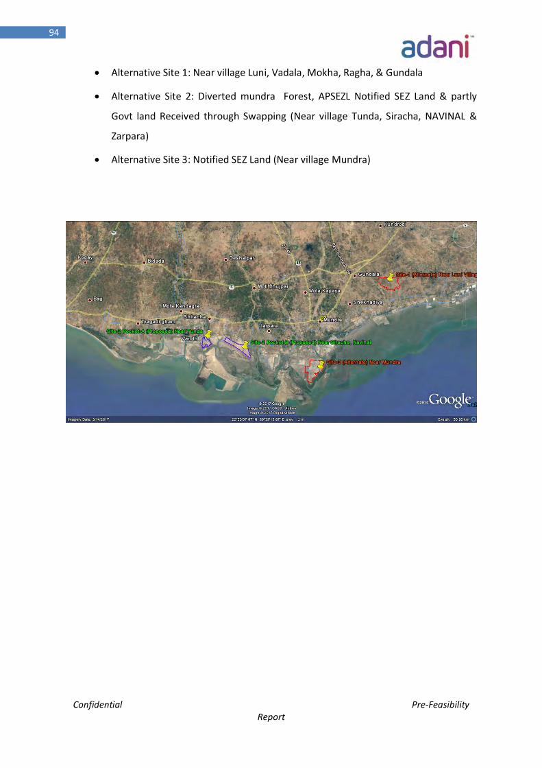
Confidential Pre-Feasibility Report
94
Alternative Site 1: Near village Luni, Vadala, Mokha, Ragha, & Gundala
Alternative Site 2: Diverted mundra Forest, APSEZL Notified SEZ Land & partly
Govt land Received through Swapping (Near village Tunda, Siracha, NAVINAL &
Zarpara)
Alternative Site 3: Notified SEZ Land (Near village Mundra)
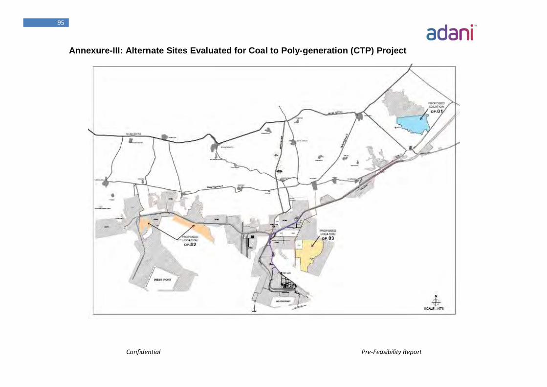
Confidential Pre-Feasibility Report
95
Annexure-III: Alternate Sites Evaluated for Coal to Poly-generation (CTP) Project
Confidential Pre-Feasibility Report
96
4.2.1 Requirements for CTP complex
Following are the requirements which should be fulfilled by the selected site for the
proposed CTP Complex consisting of the Substitute Natural Gas (SNG), Ammonia,
Methanol, Acetic Acid, Poly-Olefins, MEG, and DME plants
a. Land
The total area within the plant boundary required for the installation of above facilities
with necessary auxiliary and services units and considering a smooth operational flow will
be Approx. 635 acres (without Green Belt)
b. Water
A CTP complex consumes considerable quantity of water, bulk of which is required for
cooling purposes and the rest is utilized for process needs, drinking, sanitary and
firefighting purpose. In order to reduce the requirement of fresh water, circulation system
has been considered. In this system, the return water from various units of plant will be
reused after necessary cooling/treatment. Fresh make up water will be added to
compensate for losses in re-circulation system.
Total Water Requirement will be 400 MLD
c. Power
The plant and equipment of a CTP complex are required to run round the clock and any
un-planned interruption in the operation not only hampers the production but causes
damage to equipment also.
Total Power Requirement will be ~ 2600 MW. Part of the power ~600 MW power will be
produced from the process steam generated within the complex and rest (~2000 MW)
will be sourced from APSEZL.
Confidential Pre-Feasibility Report
97
d. Raw Material
About 35 MMTPA of Coal (raw material) will be required to produce the mentioned
products of CTP complex. The annual major raw materials required for the CTP complex
are given below:
Raw material Quantity Source
Coal 35 MMTPA Imported coal from Australia
Limestone 2.2 MMTPA Domestic – Adani Cementation Ltd
e. Road
For receipt of other raw materials at plant site and despatching of various products and
by-products from site, the region should be well connected by roads.
f. Port
Site should be well connected to the west port for receipt of Coal and for transfer
Ammonia to consumers. This will ensure lower transportation costs.
4.2.2 Criteria for Site Evaluation
As all the options are part of notified SEZ land of APSEZL, following factors will be considered
for site evaluation:
Away from environmentally sensitive areas
Availability of adequate land with favourable terrain and soil condition
Availability of infrastructural facilities viz. power, water, road and port facilities.
Proximity to the port for transportation of feedstock coal and as well as to
dispatch of final products.
Site slope and drainage pattern
Keeping the above facilities in view, an attempt is made to select a suitable site which
meets the above requirements and also results in optimization of not only the initial
investment cost but also the operating costs.
Confidential Pre-Feasibility Report
98
4.2.3 Description of all the considered sites
Site – I (In Gundala & Mokha villages )
i.Location
The proposed site is located at a distance of 30 Km east of Mundra Port in Taluk Mundra.
The sea is at a distance of approx. 8.0 km from site.
ii.Land & Terrain
The located site is outside of notified SEZ. The terrain is flat and average elevation of the
site is 8.5 m as compared to high tide level of 6.5 m.
iii.Road
Existing National Highway no. 8A etx passing north of the identified site connecting
Mundra /Mandvi is about 12 Km from the site. State Highway no. 6 is running at southern
side of the identified location which is at approx distance of 4 km from the site. The site is
connected through existing NH-8A etx at north.
iv.Water
The Requirement Water for the plant has been estimated as 400 MLD. M/s. APSEZL has
considered the project requirement and assured for supplying the total water
requirement for the plant.
v.Power
The net power requirement of power will be about 2000 MW. To meet the above
requirement the power will be made available by from 400 kV switch yard of Adani Power
Plant. Development of bay and HT line of about 0.5 km from bay to site will be developed
as infrastructure facilities.
Confidential Pre-Feasibility Report
99
vi.Port
APSEZL Mundra port facilities are located at approx. 25 km distances and Receipt of
feedstock coal will be at Mundra Port (West basin) and transfer through by road which is
approx. 30 km.
Site – II (East Side of Adani Power Plant)
i. Location
The proposed site is located at a distance of 22 Km from Mundra Town between village
Siracha and Navinal. The sea is at a distance of approx. 6 Km from site.
ii. Land & Terrain
Approx. 948.5 acres of SEZ land is available for the proposed project. The terrain is flat
and elevation of the site varies from 8 m to 10m above MSL.
iii. Road
Existing National Highway no. 8A connecting Mundra to Mandvi is about 10 Km from the
site. State Highway no. 6 is running close to the site.
iv. Water
The Requirement Water for the plant has been estimated as 400MLD. APSEZL will be
supplying the total water requirement for the plant.
v. Power
The net power requirement will be about 2000 MW. To meet the above requirement the
power will be made available from 400 kV switch yard of Adani Power Plant. Development
of bay and HT line of about 0.5 km from bay to site will be developed as infrastructure
facilities.
vi. Port
Receipt of feedstock coal will be through conveyor from west port at Mundra which is
about 4.5 Km from Site.
Confidential Pre-Feasibility Report
100
Site – III (in Mundra village)
i. Location
The proposed site is located at a distance of 7.5 Km from south of Mundra Town the sea is
adjoining the proposed site via creek at south east of the proposed site
ii. Land & Terrain
The total identified land is notified SEZ land and available for the proposed project. The
terrain is flat and average elevation of the site is +7.5 mt CD. Due to closeness of sea
iii. Road
The proposed site accessible through existing State Highway at west, which further
connecting Mundra is about 7.5 Km from the site.
iv. Water
The Requirement Water for the plant has been estimated as 400MLD. APSEZL has
considered the project requirement and assured for supplying the total water
requirement for the plant.
v. Power
The net power requirement will be about 2000 MW. To meet the above requirement the
power will be made available from 400 kV switch yard of Adani Power Plant. Development
of bay and HT line of about 20 km from bay to site will be developed as infrastructure
facilities.
vi. Port
Receipt of feedstock coal will be through conveyor from west port/South port at Mundra
which further transfer by road is about 16 Km from Site.
4.3 Evaluation of Alternative Sites
4.3.1 Salient Features of Sites Selected for Detailed Analysis
The alternative sites considered were evaluated and the details are given in Table below
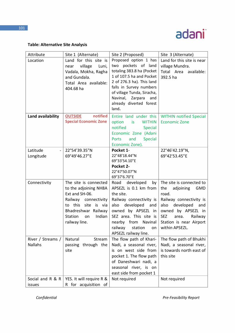
Confidential Pre-Feasibility Report
101
Table: Alternative Site Analysis
Attribute Site 1 (Alternate) Site 2 (Proposed) Site 3 (Alternate) Location Land for this site is
near village Luni, Vadala, Mokha, Ragha and Gundala. Total Area available: 404.68 ha
Proposed option 1 has two pockets of land totaling 383.8 ha (Pocket 1 of 107.5 ha and Pocket 2 of 276.3 ha). This land falls in Survey numbers of village Tunda, Siracha, Navinal, Zarpara and already diverted forest land.
Land for this site is near village Mundra. Total Area available: 392.5 ha
Land availability OUTSIDE notified Special Economic Zone
Entire land under this option is WITHIN notified Special Economic Zone (Adani Ports and Special Economic Zone).
WITHIN notified Special Economic Zone
Latitude - Longitude
22°54'39.35"N 69°49'46.27"E
Pocket 1- 22°48'18.44"N 69°33'54.10"E Pocket 2- 22°47'50.07"N 69°37'6.70"E
22°46'42.19"N, 69°42'53.45"E
Connectivity The site is connected to the adjoining NH8A Ext and SH-06. Railway connectivity to this site is via Bhadreshwar Railway Station on Indian railway line.
Road developed by APSEZL is 0.1 km from the site. Railway connectivity is also developed and owned by APSEZL in SEZ area. This site is nearby from Navinal railway station on APSEZL railway line.
The site is connected to the adjoining GMD road. Railway connectivity is also developed and owned by APSEZL in SEZ area. Railway Station is near Airport within APSEZL.
River / Streams / Nallahs
Natural Stream passing through the site
The flow path of Khari- Nadi, a seasonal river, is on west side from pocket 1. The flow path of Daneshwari nadi, a seasonal river, is on east side from pocket 1
The flow path of Bhukhi Nadi, a seasonal river, is towards north east of this site
Social and R & R issues
YES. It will require R & R for acquisition of
Not required Not required
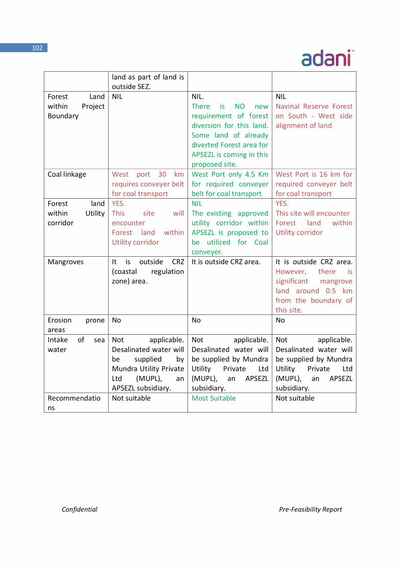
Confidential Pre-Feasibility Report
102
land as part of land is outside SEZ.
Forest Land within Project Boundary
NIL
NIL. There is NO new requirement of forest diversion for this land. Some land of already diverted Forest area for APSEZL is coming in this proposed site.
NIL Navinal Reserve Forest on South - West side alignment of land
Coal linkage West port 30 km requires conveyer belt for coal transport
West Port only 4.5 Km for required conveyer belt for coal transport
West Port is 16 km for required conveyer belt for coal transport
Forest land within Utility corridor
YES. This site will encounter Forest land within Utility corridor
NIL The existing approved utility corridor within APSEZL is proposed to be utilized for Coal conveyer.
YES. This site will encounter Forest land within Utility corridor
Mangroves It is outside CRZ (coastal regulation zone) area.
It is outside CRZ area. It is outside CRZ area. However, there is significant mangrove land around 0.5 km from the boundary of this site.
Erosion prone areas
No No No
Intake of sea water
Not applicable. Desalinated water will be supplied by Mundra Utility Private Ltd (MUPL), an APSEZL subsidiary.
Not applicable. Desalinated water will be supplied by Mundra Utility Private Ltd (MUPL), an APSEZL subsidiary.
Not applicable. Desalinated water will be supplied by Mundra Utility Private Ltd (MUPL), an APSEZL subsidiary.
Recommendations
Not suitable Most Suitable Not suitable
Confidential Pre-Feasibility Report
103
4.3.2 Merits & demerits
Site-I
The site is connected to the adjoining NH8A Ext and SH-06. Site is approx. 30 km
distance from the west port and land is flat. Distance of water and power sources are
more as compared to other identified site.
Site-II
Distance of power and water sources is less as compared to Site -I and III. Raw material
transportation distance is also less when compared to other sites. Land is high and
terrain is flat. Site has weightage in respect of water, power source and raw material
transportation from port.
Site-III
The site is connected to the adjoining GMD road. Distance from water and power source
is more compared to other identified site. Raw material transportation distance is more
as compared to other identified site Land is high and terrain is flat. Bushes/jungle
clearance and tree cutting is involved for setting up the plant.
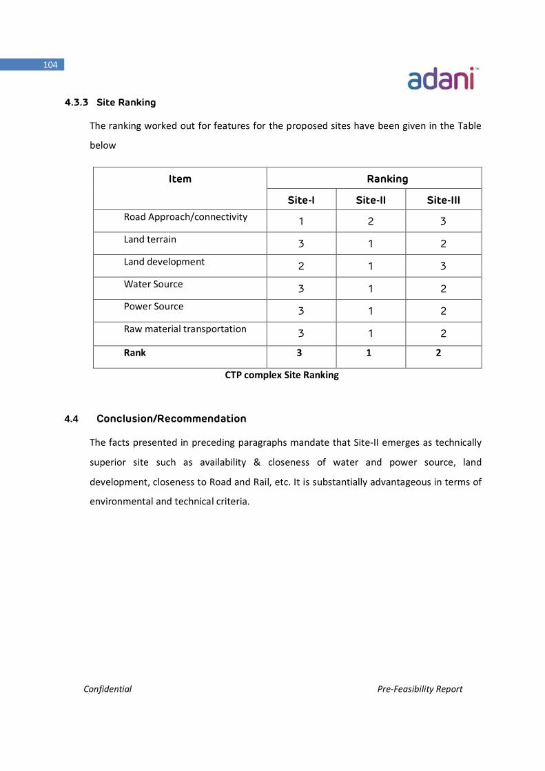
Confidential Pre-Feasibility Report
104
4.3.3 Site Ranking
The ranking worked out for features for the proposed sites have been given in the Table
below
Item Ranking
Site-I Site-II Site-III Road Approach/connectivity 1 2 3
Land terrain 3 1 2
Land development 2 1 3
Water Source 3 1 2
Power Source 3 1 2
Raw material transportation 3 1 2
Rank 3 1 2
CTP complex Site Ranking
4.4 Conclusion/Recommendation
The facts presented in preceding paragraphs mandate that Site-II emerges as technically
superior site such as availability & closeness of water and power source, land
development, closeness to Road and Rail, etc. It is substantially advantageous in terms of
environmental and technical criteria.
Confidential Pre-Feasibility Report
105
Chapter -5 Planning Brief
Confidential Pre-Feasibility Report
106
Planning Brief 5. Planning Brief
5.1 Planning Concept
The proposed CTP Complex of Adani Synenergy Limited (ASL) would require a total land
area of 948.5 Acres (384 Hectares). The detail Break-up of land required for various facilities
of CTP complex is enclosed as Annexure-IV
The CTP Complex will require above area for CTP plant & related facilities, Green Belt Area
as well as common infrastructure requirement to support the World Class CTP complex.
Land required for corridors for Power/Road/Coal Conveyor/Product pipelines is not
included in the above area.
Annexure-V shows Plot Plan of the typical CTP Complex and associated facilities. This Area
is based on a preliminary plot plan which has been developed taking into account the CTP
facility process, the site infrastructure requirements and external interfaces. The unit block
sizes and spacing on this Plot Plan are based on previously developed and engineered plant
layouts.
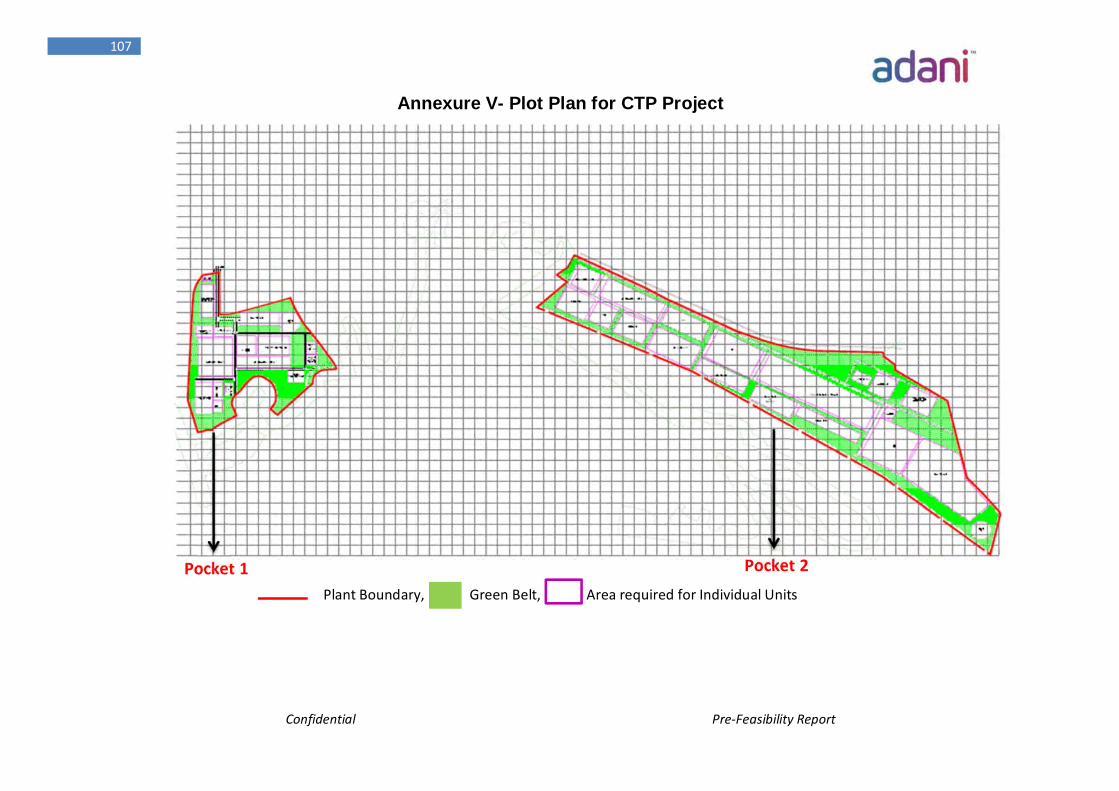
Confidential Pre-Feasibility Report
107
Annexure V- Plot Plan for CTP Project
Plant Boundary, Green Belt, Area required for Individual Units
Pocket 1 Pocket 2
Confidential Pre-Feasibility Report
108
5.2 Land Justification of CTP Complex:
CTP Plant:
CTP Plant would comprise of Land for following Units:-
Coal Preparation, Coal Receiving & Storage/Handling
Coal Gasification Island
ASU/Shift Converter/AGRU/SRU/
SNG Methanator and SNG Distribution
Methanol Synthesis
LNW/Cold Box/PSA
Ammonia Plant
MEG Plant
Acetic Acid Plant
Methanol to Poly Olefins
DME Plant
The above facilities would require land around 322 Acres.
CTP Utilities and other Infrastructure:-
Based on preliminary estimates, the CTP Infrastructure would require an additional 313
Acres of land which includes facilities like
Steam generator/ Turbine Generator
Waste Water Treatment Unit
DM Water/CPU unit
Flare& Associated facilities
Tank Farm
Slag storage
Pipelines/ Pipe Racks/ Trenches, Cable Trays
Railway siding
Confidential Pre-Feasibility Report
109
Road/Drainage
Logistical area requirements, e.g. Truck loading and unloading area, Dispatch
Section and corridors for coal and product transportation.
Non-Plant Building (Workshop, Laboratories, Admin Buildings, Training Block,
Security Room, Site Offices, Canteens OHC etc.)
General Stores/Warehouses
Bridges
Construction lay down Area
Buffer Zone
Fabrication Yards
Gate House/ Time Office
Fire & Safety Department etc.
CTP Township:-
No separate Township has been planned for CTP Complex. The house for O&M
personnel would be provided at Adani’s existing township by augmenting the township,
which is around 30 km away from the proposed CTP Complex.
GREEN BELT:-
Out of the entire area of proposed CTP complex, 33% of total CTP complex area which is
around 313.5 Acres of land is reserved for Green Belt development as per prevailing
guidelines from GSPCB/CPCB/MOE & F.
5.3 Land Use Plan:
The CTP Complex will require plot areas for the CTP and related common facilities. The
proposed CTP Complex of Adani Synenergy Ltd. would require a total land area of 948.5
Acres (384 Hectares). Also, the detailed Land Break-up of entire CTP Complex is attached
as Annexure-IV.
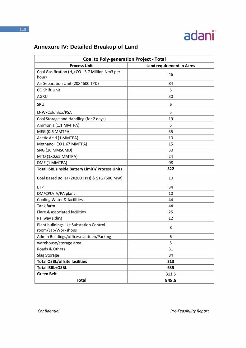
Confidential Pre-Feasibility Report
110
Annexure IV: Detailed Breakup of Land
Coal to Poly-generation Project - Total Process Unit Land requirement in Acres
Coal Gasification (H2+CO - 5.7 Million Nm3 per hour) 46
Air Separation Unit (20X4600 TPD) 84 CO Shift Unit 5 AGRU 30
SRU 6
LNW/Cold Box/PSA 5 Coal Storage and Handling (for 2 days) 19 Ammonia (1.1 MMTPA) 5 MEG (0.6 MMTPA) 35 Acetic Acid (1 MMTPA) 10 Methanol (3X1.67 MMTPA) 15 SNG (26 MMSCMD) 30 MTO (1X0.65 MMTPA) 24 DME (1 MMTPA) 08 Total ISBL (Inside Battery Limit)/ Process Units 322
Coal Based Boiler (2X200 TPH) & STG (600 MW) 10
ETP 34 DM/CPU/IA/PA plant 10 Cooling Water & facilities 44 Tank farm 44 Flare & associated facilities 25 Railway siding 12 Plant buildings like Substation Control room/Lab/Workshops 8
Admin Buildings/offices/canteen/Parking 6 warehouse/storage area 5 Roads & Others 31 Slag Storage 84 Total OSBL/offsite facilities 313 Total ISBL+OSBL 635 Green Belt 313.5
Total 948.5
Confidential Pre-Feasibility Report
111
The area earmarked for proposed CTP complex is owned by APSEZL and free from any
human activities. The proposed area is non-CRZ land.
5.4 CTP Infrastructure Requirements:
The analysis of necessary infrastructure is an important step in any project. The CTP
venture operates in a complex environment and needs reliable access to critical
infrastructure resources like Power, Water as well as infrastructure linkages like Road,
Rail, Port and Air connectivity. These key infrastructure requirements are elaborated
below based on various studies done by venture so far
Physical Infrastructure needs:
Water:
APSEZL will provide the RO (reverse osmosis) water for the CTP complex. The total net
water consumption for CTP is about 400 MLD.
An integrated water system is proposed where effluent from the process units is treated
and reused to reduce water demand.
Water demand is made up of the following:
• Make-up losses for BFW (Boiler Feed Water) preparation
• Steam losses from the steam and power systems
• Steam consumed directly in the process (e.g. steam used in the gasification
process)
• Evaporation & drift losses from the cooling Exchangers/Circuits.
Confidential Pre-Feasibility Report
112
Power
The total power requirement of the facility is 2600 MW. The By-product VHP, HP & MP
Steam which is produced from various process units of CTP plant would be used for the
power generation. Therefore part of the power requirement (around 600 MW) would
be met using Process Steam Turbine. Remaining power requirement would met by
APSEZL. The remaining power requirement @2000 MW would be sourced from APSEZL.
Power is distributed within the plant at 3 phase, 11 kV and 50 Hz via a number of
substation unit. The APL’s power plant is around 2 km away from the proposed CTP site.
The construction power requirement of around 20 MW would be sourced from the
APSEZL.
Road Linkage
The site is well connected by the National / State Highways, broad gauge rail link and is
about 3.0 km away from the Navinal railway Station. Hence, transportation of materials
to the project site will not be a major constraint.
Further studies are planned on these specific connections and access routes to
determine the impact of increased traffic volumes.
Rail Linkage
The nearest railway stations to the proposed site are Adipur/Gandhidham which is 63
KM away from the CTP Complex.
The distance from existing railway line of APL’s Gate No-4 to proposed CTP Complex is
around 3.2 km.
Confidential Pre-Feasibility Report
113
Port Connectivity
The Port of Mundra is India’s biggest private port. Located in the Kutch district of the
state of Gujarat, Mundra lies on the north shores of the Gulf of Kutch about 50
kilometers south of Anjar and 44 kilometers east the Port of Mandvi.
The Port of Mundra is not only a private port, but it is also a special economic zone.
Incorporated in 1998 as Gujarat Adani Port Limited (GAPL), the company began
operating in 2001. The Mundra Special Economic Zone was incorporated in 2003 and
was merged with GAPL in 2006. The combined company was renamed to “Mundra Port
and Special Economic Zone Limited” and now is Adani Ports & Special Economic Zone
Limited (APSEZL). It is India’s first multi-product port-based special economic zone (SEZ).
The Port of Mundra and SEZ hopes to be a global player and preferred partner that
pursues innovation in business, technological, and commercial areas. It strives to add
value to partners’ activities and efforts while reducing its impact on the environment.
The Port of Mundra and SEZ is responsible for acquiring, developing, and managing
knowledge to become experts in the field and to apply that knowledge across their
range of business interests. As a private port, the Port of Mundra also seeks to ensure
tangible and intangible profits.
The Port of Mundra offers 21 closed dockside warehouses (go-downs) with capacity for
137 thousand square meters to store wheat, sugar, rice, fertilizer and fertilizer raw
materials, and deoiled cakes. The port offers 880 thousand square meters of open
storage for steel sheets, coils, plate, clinker, scrap, salt, coke, bentonite, and coal. An
additional 26 thousand square meters of open storage is available alongside the railway.
The port also offers a wheat-cleaning facility with capacity to handle 1200 metric tons
per day and a rice-sorting and –grading facility that can handle 500 metric tons per day.
The Port of Mundra is planning several additions and improvements. A new terminal site
is proposed to be located about ten nautical miles west of the current terminals at the
Confidential Pre-Feasibility Report
114
Port of Mundra. The terminal will eventually contain three deep-water offshore berths
and two sets of stackyards for coal, iron ore, and other dry bulk cargo.
The town’s showpiece is the Port of Mundra, which has transformed the local economy
and atmosphere. The Port of Mundra was the place in addition to Abadasa and Lakhpat
talukas in Kutch which were not seriously damaged in the 2001 Gujarat earthquake that
devastated rest of the district.
The current capacity of port to handle 2.5 m TEU's is to be expanded to 5 m TEU by
2015, making it india's second largest container port.The coal would be imported
through West Port which is around 4.5 km away from the proposed CTP site.
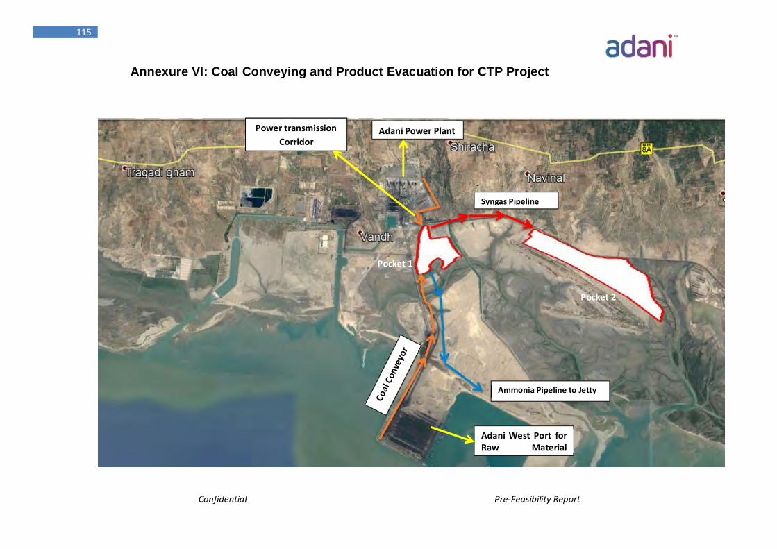
Confidential Pre-Feasibility Report
115
Annexure VI: Coal Conveying and Product Evacuation for CTP Project
Adani West Port for Raw Material
Syngas Pipeline
Ammonia Pipeline to Jetty
Power transmission Corridor
Adani Power Plant
Pocket 1
Pocket 2
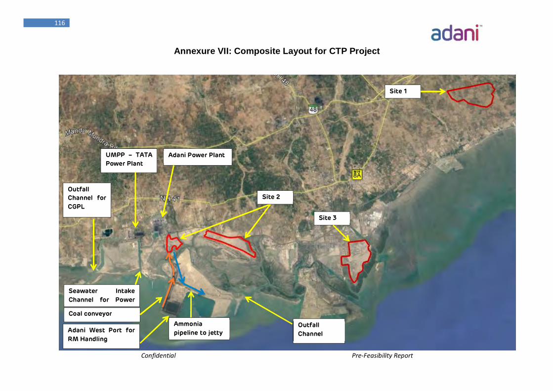
Confidential Pre-Feasibility Report
116
Outfall Channel for CGPL
Seawater Intake Channel for Power
Site 1
UMPP – TATA Power Plant
Adani Power Plant
Coal conveyor
Site 3
Site 2
Outfall Channel Adani West Port for
RM Handling
Ammonia pipeline to jetty
Annexure VII: Composite Layout for CTP Project
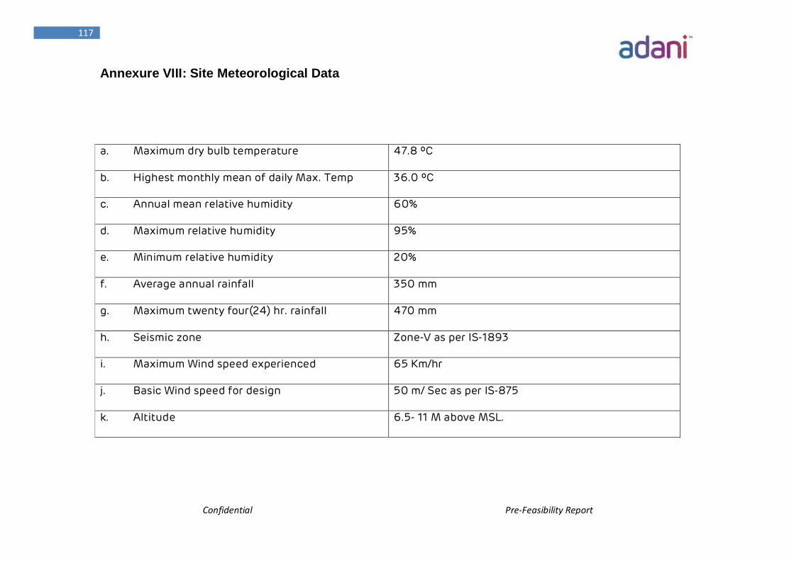
Confidential Pre-Feasibility Report
117
Annexure VIII: Site Meteorological Data
a. Maximum dry bulb temperature 47.8 ºC
b. Highest monthly mean of daily Max. Temp 36.0 ºC
c. Annual mean relative humidity 60%
d. Maximum relative humidity 95%
e. Minimum relative humidity 20%
f. Average annual rainfall 350 mm
g. Maximum twenty four(24) hr. rainfall 470 mm
h. Seismic zone Zone-V as per IS-1893
i. Maximum Wind speed experienced 65 Km/hr
j. Basic Wind speed for design 50 m/ Sec as per IS-875
k. Altitude 6.5- 11 M above MSL.
Confidential Pre-Feasibility Report
118
Air Connectivity
The proposed Mundra site is 60 km away from Bhuj Airport, 65 KM away from Kandla
Airport and 460 km away from the nearest commercial airport, Ahmedabad. Adani
Groups own Airstrip is around 25 km away from the proposed site.
Social Infrastructure needs:
Development of physical infrastructure cannot usher in overall development at the
desired level if the social infrastructure is not simultaneously developed. Education,
Health, Social security, public entertainment etc. has to be developed to ensure proper
social infrastructure.
Educational Initiatives:
Infrastructural Development in the form of school building, teaching &
learning equipment and furniture & Fixtures etc.
Quality Teacher support
Scholarship for Education Excellence
Promotion of Girl Child Education
Incorporation of Extra Curricular activities
Health:
ASL would take care of all the medical requirements of the CTP complex by establishing
a hospital with quality doctors. In addition different awareness programs would be
conducted as furnished below.
Addressing the Mother & Child Health
Support to the Nutritional Program of Mother, Child & School goers.
Support the District Health administration in the community health activities
Improvement of town Sanitation through Solid- Liquid Waste Management.
Knowledge Enhancement on Preventive Health Care.
Confidential Pre-Feasibility Report
119
Chapter -6 Proposed Infrastructure
Confidential Pre-Feasibility Report
120
Proposed Infrastructure
6. Proposed Infrastructure
6.1 Industrial Area (Processing Area):
The proposed CTP Complex including Coal Preparation Plant of Adani Synenergy Limited
would require a total land area of 948.5 Acres (3.84 km2 or 384 Hectares). This area is
based on a plot plan of CTP complex as Annexure V which has been developed taking
into account the CTP facility process, the site infrastructure requirement and external
interfaces. These areas will be firmed up with ongoing engineering studies to suit the
facility’s operating conditions, construction and maintenance philosophies and storage
requirements.
CTP Plant area of around 322 Acres of land would comprise of Coal Preparation Plant,
Coal gasification and purification plant, Downstream Ammonia, Acetic Acid, MEG,
Methanol to olefins, Poly Olefins, DME and SNG plants
The CTP Infrastructure would require around 313 Acres of land which includes facilities
like Waste Water Treatment Unit, Steam Boiler, Steam Turbine (600 MW),
Product/Intermediate Product Storage etc Pipelines, Loading/Unloading,
Road/Drainage, Pipe Racks/Trenches & Cable Trays, Buffer Zone, Non Plant Buildings,
Laboratories, Fabrication Yard, Dispatch Section, General stores/ Warehouse, Fire &
Safety Department, Maintenance Workshop, Occupational Health Center etc.
Therefore, the land considered for the CTP Industrial Area (Processing Units) is around
635 Acres.
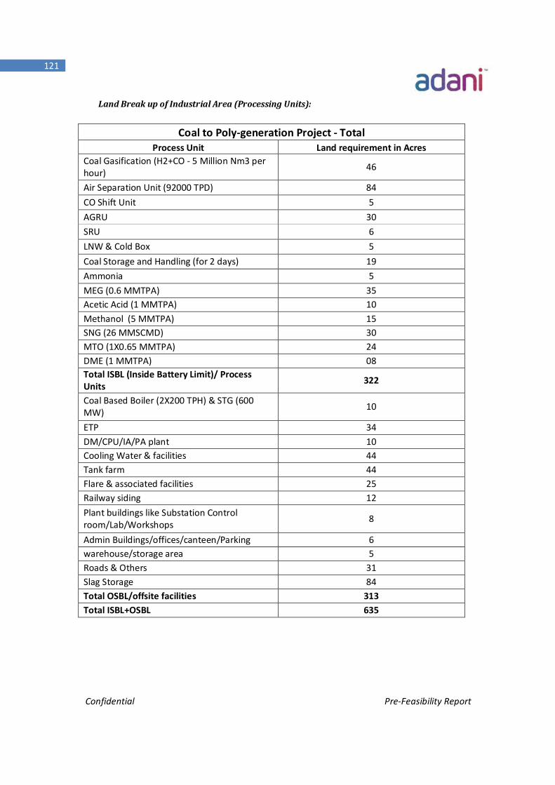
Confidential Pre-Feasibility Report
121
Land Break up of Industrial Area (Processing Units):
Coal to Poly-generation Project - Total Process Unit Land requirement in Acres
Coal Gasification (H2+CO - 5 Million Nm3 per hour) 46
Air Separation Unit (92000 TPD) 84 CO Shift Unit 5 AGRU 30 SRU 6 LNW & Cold Box 5 Coal Storage and Handling (for 2 days) 19 Ammonia 5 MEG (0.6 MMTPA) 35 Acetic Acid (1 MMTPA) 10 Methanol (5 MMTPA) 15 SNG (26 MMSCMD) 30 MTO (1X0.65 MMTPA) 24 DME (1 MMTPA) 08 Total ISBL (Inside Battery Limit)/ Process Units 322
Coal Based Boiler (2X200 TPH) & STG (600 MW) 10
ETP 34 DM/CPU/IA/PA plant 10 Cooling Water & facilities 44 Tank farm 44 Flare & associated facilities 25 Railway siding 12 Plant buildings like Substation Control room/Lab/Workshops 8
Admin Buildings/offices/canteen/Parking 6 warehouse/storage area 5 Roads & Others 31 Slag Storage 84 Total OSBL/offsite facilities 313 Total ISBL+OSBL 635
Confidential Pre-Feasibility Report
122
6.2 Green Belt:
Out of the entire area of proposed CTP complex, 33% of total CTP complex area which is
around 313.5 Acres of land is reserved for Green Belt development as per prevailing
statutory guidelines from GSPCB/CPCB/MOE & F.
The Land Break-up for Non Processing Area is tabulated in Below Table:
Land Break up of Non Processing Units:
Green Belt (acres) 313.5 Total Non-processing area (acres) 313.5
6.3 Social Infrastructure:
ASL believes that an effective growth policy must also take into account the fulfillment
of basic needs of the masses, especially of those living in rural areas.
ASL has one of the best social infrastructure proposals which are based on the
implementation already done by APSEZL and APL at Mundra, in the core area of Health,
Education, Sustainable livelihood options & women empowerment, Community
infrastructure, Youth sport & cultural activities, Calamity management. ASL is strictly
committed and is going to implement the proposal to uplift the social infrastructure
surroundings the CTP area.
The key highlights of some initiatives & activities to improve social infrastructure that
ASL is going to undertake at Mundra are:
Sustainable livelihood options & Women Empowerment:
Strengthening the Community Based Organizations like Self-Help Groups, Farmer
Federation etc.
Confidential Pre-Feasibility Report
123
Capacity Building of the underprivileged communities on various market driven
skills
Establishment of Forward & Backward Market Linkages through networking
Facilitating the easy reach to the technical institutions for knowledge up gradation.
Promotion of livestock health management
Education Initiatives:
Skill up gradation through establishment of Technical Training Institution
Infrastructural Development in the form of school building, teaching & learning
equipment and furniture & Fixtures etc.
Quality Teacher support
Scholarship for Education Excellence
Promotion of Girl Child Education
Incorporation of Extra Curricular activities
Holistic approach to the education through “Yoga & Art Of Living”
Promotion of Functional Literacy
Health Initiatives:
Addressing the Mother & Child Health
Support to the Nutritional Program of Mother, Child & School goers.
Control on Blindness, Malaria, T.B., HIV & AIDS, Diarrhea etc.
Support the District Health administration in the community health activities
Improvement of Village Sanitation through Solid- Liquid Waste Management.
Knowledge Enhancement on Preventive Health Care
Community Infrastructure & facilities:
Enhancement of Green Coverage
Protection of Wildlife through awareness generation
Promotion of Renewal Energy
Confidential Pre-Feasibility Report
124
Waste Management through installation of recycling measures
Natural Resource Management:
Enhancement of Green Coverage
Ground Water Recharge through Water Harvesting
Protection of Wildlife
Solid & liquid Waste Management
Promotion of use of Renewal Sources of Energy
Youth, sports & culture:
Promotion of brotherhood & fraternity within the village youths
Development of Sports Activities
Nurturing the youth for participation at District, state and National level events.
6.4 Connectivity:
Brief Profile of Kutch District:
Kutch district is a District in Gujarat state in western India. Covering an area of 45,652
sq. km, it is the largest district of India.
The administrative headquarters is in Bhuj which is geographically in the center of
district. Other main towns are Gandhidham, Rapar, Nakhatrana, Anjar, Mandvi,
Madhapar, Mundra and bhachau. Kutch has 969 villages. Kala Dungar (Black Hill) is the
highest point in Kutch at 458 metres (1,503 ft).
Kutch is virtually an island, as it is surrounded by the Arabian Sea in the West; the Gulf
of Kutch in South and South-East and Rann of Kutch in North and North-East. The border
with Pakistan lies along the Northern edge of the Rann of Kutch, of the disputed Kori
Creek. The Kutch peninsula is an example of active fold and thrust tectonism. In Central
Kutch there are four major east-west hill ranges characterized by fault propagation folds
with steeply dipping northern limbs and gently dipping southern limbs.
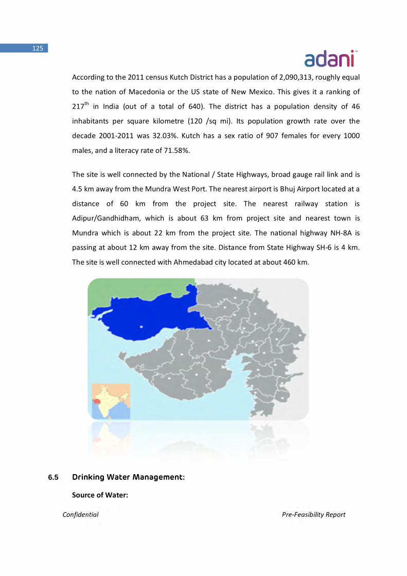
Confidential Pre-Feasibility Report
125
According to the 2011 census Kutch District has a population of 2,090,313, roughly equal
to the nation of Macedonia or the US state of New Mexico. This gives it a ranking of
217th in India (out of a total of 640). The district has a population density of 46
inhabitants per square kilometre (120 /sq mi). Its population growth rate over the
decade 2001-2011 was 32.03%. Kutch has a sex ratio of 907 females for every 1000
males, and a literacy rate of 71.58%.
The site is well connected by the National / State Highways, broad gauge rail link and is
4.5 km away from the Mundra West Port. The nearest airport is Bhuj Airport located at a
distance of 60 km from the project site. The nearest railway station is
Adipur/Gandhidham, which is about 63 km from project site and nearest town is
Mundra which is about 22 km from the project site. The national highway NH-8A is
passing at about 12 km away from the site. Distance from State Highway SH-6 is 4 km.
The site is well connected with Ahmedabad city located at about 460 km.
6.5 Drinking Water Management:
Source of Water:
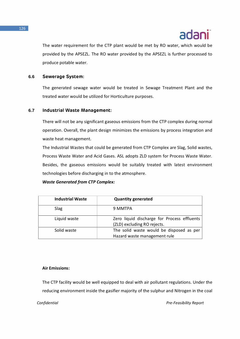
Confidential Pre-Feasibility Report
126
The water requirement for the CTP plant would be met by RO water, which would be
provided by the APSEZL. The RO water provided by the APSEZL is further processed to
produce potable water.
6.6 Sewerage System:
The generated sewage water would be treated in Sewage Treatment Plant and the
treated water would be utilized for Horticulture purposes.
6.7 Industrial Waste Management:
There will not be any significant gaseous emissions from the CTP complex during normal
operation. Overall, the plant design minimizes the emissions by process integration and
waste heat management.
The Industrial Wastes that could be generated from CTP Complex are Slag, Solid wastes,
Process Waste Water and Acid Gases. ASL adopts ZLD system for Process Waste Water.
Besides, the gaseous emissions would be suitably treated with latest environment
technologies before discharging in to the atmosphere.
Waste Generated from CTP Complex:
Air Emissions:
The CTP facility would be well equipped to deal with air pollutant regulations. Under the
reducing environment inside the gasifier majority of the sulphur and Nitrogen in the coal
Industrial Waste Quantity generated
Slag 9 MMTPA
Liquid waste Zero liquid discharge for Process effluents (ZLD) excluding RO rejects.
Solid waste The solid waste would be disposed as per Hazard waste management rule
Confidential Pre-Feasibility Report
127
is converted into H2S and NH3, which are absorbed in the Gas Clean-Up Section. The
Sulphur Recovery unit also converts Mercaptans and COS present in the syngas into
Saleable Sulphur. So, the quantity of SOx, NOx and particulate matter in the flue gas from
the CTP Complex would be very less. Moreover, these emissions would be reduced with
the latest environmental technologies and are well within the permissive levels of
emission, as stipulated by Central/State Pollution Control Boards, Ministry of
Environment & forest (MOEF&CC) & World Bank Standards, before discharge into the
atmosphere.
The following steps would be taken to reduce air emissions with examples of abatement
technologies:
1. Sulphur Dioxide (SO2): A Sulphur Recovery Unit for the recovery of saleable
Sulphur;
2. Particulate Matter: Wet Scrubbers, Cyclones, Electrostatic Precipitators, Fabric
Filters.
3. VOC Emissions: Dual Mechanical Seals on pumps, closed vent systems, closed loop
sampling etc.
The final gaseous emissions from the CTP Complex would be well within the Permissible
Limits as prescribed by GSPCB/CPCB/MOEF&CC.
Waste Water Management:
The CTP waste water treatment system consists of:
ETP/Process Waste Water Treatment Plant.
General Waste Water Treatment Plant.
Sewage Treatment Plant
The Process Waste Water generated from Gasification, SNG, Methanol and other CTP Units
is treated necessarily in Bio/Chemical Effluent Treatment Plant, Tertiary treatment plant
and Multiple Effective evaporator (MEE) and then recycled for reuse within Plant Battery
Confidential Pre-Feasibility Report
128
Limit. Dry sludge/salts from MEE (around 13 TPH) shall be disposed through authorized
agencies as per Hazardous Waste Management (HWM) Rule
The site philosophy is to minimize the import of raw water by maximizing the re-use of
wastewater within the CTP facility. The waste water system is highly integrated and is
designed for Zero Liquid Discharge (ZLD).
The generated sewage waste water would be treated in Sewage Treatment Plant and the
treated water would be used for Horticulture purposes.
6.8 Solid Waste Management:
The main solid waste from the Plant is the Slag from the Gasification Island. The total
amount of Slag generated from the Gasification Island is about 9 MMTPA. Slag generated
out of Gasification Island is non-leachable, non-hazardous and easily conforms to the
regulatory limits for metals and organics and standard waste characteristic tests for
toxicity, reactivity, ignitibility, and corrosiveness.
Options would be explored to maximize the utilization of coal Slag in the following areas:
1. Road/ Embankment Making
2. Structural filling
3. Land development
4. Cement Making
5. Synthetic Aggregate Making
6. Mine backfilling
Of these, a number of applications were tested and tried and found to be suitable for high
volume applications. In particular, the utilization of slag in applications such as road and
construction aggregates, cement additives, and lightweight aggregates has been
demonstrated successfully
Confidential Pre-Feasibility Report
129
Slag in Cement and Concrete
The composition of the slag and its natural pozzolanic properties are similar to the raw
material used to make Portland cement clinker. The slag could also be added to cement
clinker and ground with it.
Many tests to replace some of the fine aggregate used to make concrete with slag were
performed showcasing compressive strengths similar to cement content. These results
indicate that slag can be successfully used for concrete applications
Slag Lightweight Aggregate:
Lightweight aggregates (LWA) have unit weights that are approximately 40-60% those of
standard aggregates. Major applications of LWA are in the production of lightweight
structural concrete used in high rise buildings and lightweight precast products such as
roofing tiles, masonry blocks, utility vaults, cement concrete pipes, etc. Currently, slag
based lightweight aggregates (SLA) are being used successfully
Slag usage References:
Some of the reference plants along with their slag utilisation methods are mentioned
below.
As per the information from technology licensor, Slag from the Wabash River IGCC
plant in USA is being utilized for concrete cement feedstock, road construction
applications such as filler for asphalt, blasting grit, roofing material, structural fill, and
alternative landfill cover
Apart from these there are number of Chinese gasification plants are utilising slag for
cement feedstock, road construction applications and LWA materials.
Confidential Pre-Feasibility Report
130
For the initial years of CTP plant operation till sustained Slag Utilization/Management in
the above application areas are developed, as well as for emergency purpose, a Slag
Storage Area/Pond of 84 Acres would be made for intermediate/emergency storage of
coal Slag. The other solid wastes generated like spent catalyst, discarded resins and
molecular sieves will be disposed as per hazardous waste management rule.
Provision would be made to reclaim the disposed Slag from Slag pond at a later stage for
various utilization ventures.
6.9 Power Requirement & Supply:
The total power requirement of the facility is 2600 MW. The By-product SHP, HP & MP
Steam which is produced from various process units of CTP plant would be used for the
power generation. Therefore part of the power requirement (around 600 MW) would be
met using Process Steam Turbine. Remaining power requirement would met by APSEZL.
Estimated Power Consumption by CTP Project : - 2600 MW
Power generation from process Steam : - 600 MW
Net Import : - 2000 MW
The construction power (@20 MW) and CTP operating Power (@2000 MW) would be
sourced from the APSEZL.
Confidential Pre-Feasibility Report
131
Chapter -7 Rehabilitation & Resettlement Plan
Confidential Pre-Feasibility Report
132
Rehabilitation & Resettlement Plan
7. Rehabilitation & Resettlement Plan
The land proposed for the CTP project has no human inhabitation. The land is also free from
any human activity since the land is quite distant from established villages nearby. All the
villagers live in nearby Tunda, siracha and Navinal villages.
The CTP construction and Operational activities would not affect villagers living in nearby
village. So, CTP project requires no rehabilitation and resettlement activities.
Confidential Pre-Feasibility Report
133
Chapter -8 Project Schedule & Cost Estimate
Confidential Pre-Feasibility Report
134
CHAPTER – 8 Project Schedule & Cost Estimate
8. Project Schedule & Cost Estimate
8.1 General
Successful execution on the Coal to Poly-generation (CTP) Complex calls for well thought
out project execution strategies and an elaborate Project Implementation plan for carrying
out a whole range of critical activities such as
Selection of Technology/ Process Licensor
Project Financing (Financial Closure)
Pre Project Activities
Statutory Approval
Project Execution Philosophy and Plan
Project Coordination Procedures
Project Management, Monitoring, Control & Feedback, System & Services
Management of Technology Transfer
Basic Engineering / Front End Engineering
Detailed Engineering
Procurement
Monitoring and Expediting Manufacturing & Fabrication activities
Construction Management
Inventory and Warehousing Control
Quality Assurance and Quality Control
Organizing and deployment of skilled labor and Skilled Contractors
Training of plant personnel to take over operations on completion of
construction activity
Confidential Pre-Feasibility Report
135
Pre-commissioning, commissioning and performance testing of all systems and
putting in operation
Maintenance Management
All the above activities can be phased in such a manner that the project is executed in the
most efficient and optimized economic course with a defined time schedule governed by
overall project schedule & the implementation Bar chart.
Execution of the Mega Project like CTP essentially demands for a strong Project Execution
Team consisting of experts in each of the above identified activities. Besides: the
responsibility and reporting matrix needs to be well defined.
The Project Execution plan (PEP) can be further elaborated Post approvals.
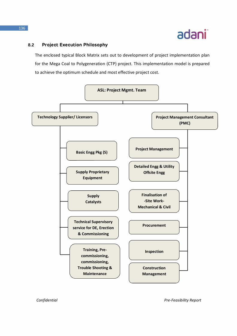
Confidential Pre-Feasibility Report
136
8.2 Project Execution Philosophy
The enclosed typical Block Matrix sets out to development of project implementation plan
for the Mega Coal to Polygeneration (CTP) project. This implementation model is prepared
to achieve the optimum schedule and most effective project cost.
ASL: Project Mgmt. Team
Project Management Consultant (PMC)
Technology Supplier/ Licensors
Project Management
Basic Engg Pkg (S)
Inspection
Supply Catalysts
Supply Proprietary Equipment
Training, Pre-commissioning, commissioning,
Trouble Shooting & Maintenance
Technical Supervisory service for DE, Erection
& Commissioning
Procurement
Detailed Engg & Utility Offsite Engg
Finalisation of -Site Work-
Mechanical & Civil
Construction Management
Confidential Pre-Feasibility Report
137
8.3 Project Implementation Plan (PIM)
Generally: The project can be executed in the following manner:
Phase 1: Detailed planning phase including licensor selection, basic engineering, and
detailed engineering
Phase 2: Awarding of PMC (Project Management Consultant/LSTK procurement &
construction) contract, ordering of long delivery items.
Phase 3: Completion of all contracts for realization of the project as elaborated earlier.
The various phases elaborated briefly herein is General but essential for execution for
the envisaged mega project like CTP
Phase 1: Detailed Planning phase
This phase of the project covers the following critical activities:
Financial approval of the board following DFR and DPR stages
Selection of Technology Supplier
Study and planning of transportation of capital & construction equipment
Site development planning & selection of contractor
Authority approval (various Stages i.e. EIA, EMP etc.)
Cost optimization
Completion of Basic Engineering Package & Review of DPR
Completion of detail engineering
Negotiation of PMC & Selection
Phase 2:
Awarding of PMC
Project Control: Engineering Phase
Ordering of high lead-time equipment etc.
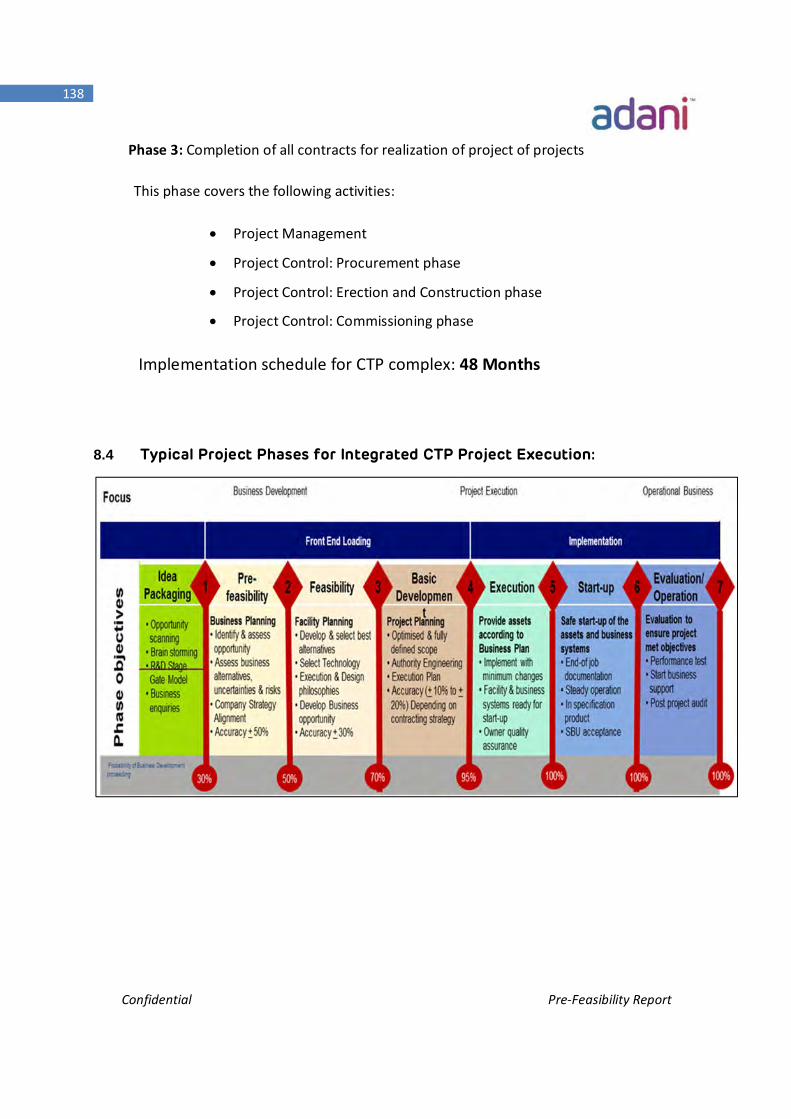
Confidential Pre-Feasibility Report
138
Phase 3: Completion of all contracts for realization of project of projects
This phase covers the following activities:
Project Management
Project Control: Procurement phase
Project Control: Erection and Construction phase
Project Control: Commissioning phase
Implementation schedule for CTP complex: 48 Months
8.4 Typical Project Phases for Integrated CTP Project Execution:
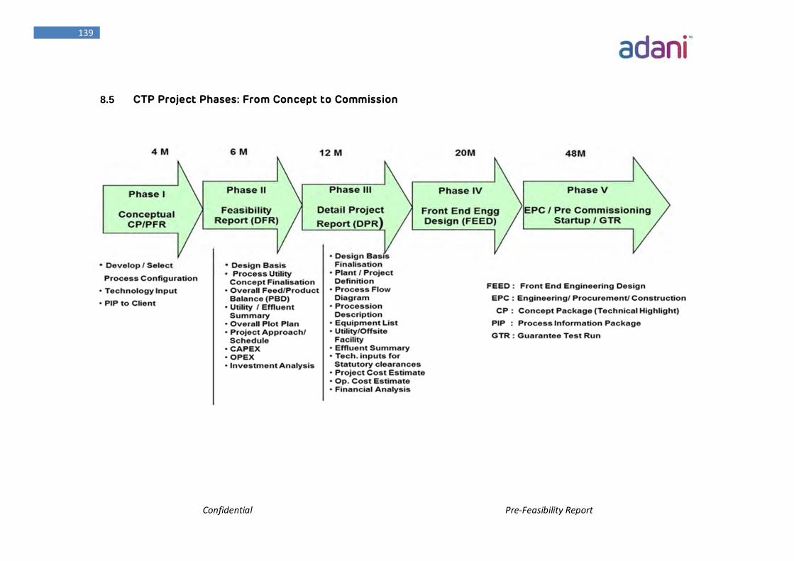
Confidential Pre-Feasibility Report
139
8.5 CTP Project Phases: From Concept to Commission
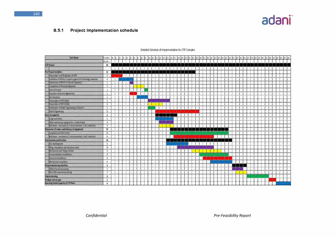
Confidential Pre-Feasibility Report
140
8.5.1 Project Implementation schedule
Confidential Pre-Feasibility Report
141
8.6 Financial Analysis:
The project cost has been estimated on the basis of identified scope, engineering details
for cost estimation, licensor’s information and cost data for Engineering, Procurement
and Construction management (EPCM) mode of execution. A reasonable contingency
factor has been incorporated for the unforeseen items.
The total estimated project Cost of the CTP project is around 15 Billion USD (Rs. 1, 00,
000 Cr.). The estimation basis is mentioned below
ESTIMATE BASIS
ASL has prepared capacity-factored capital cost estimates for the gasification island,
SNG Island, Methanol Island and other CTP units. Capital costs cover the engineering,
procurement, and construction (EPC) of a CTP facility.
The estimates are all Class 5 type, with an accuracy range of -15% to +40% (as defined in
the Association for the Advancement of Cost Engineering (AACE) International
Recommended Practice No. 18R-97).
Each estimate case is prepared primarily by capacity factoring reference unit/systems.
Budget estimates from recent Licensor’s project database for Air Separation, Acid Gas
Removal (Rectisol), Sulphur Recovery, Tail-Gas Treatment, Syngas Booster, Power
Generation, and ZLD Wastewater Treating units are adjusted to the required capacity
per train, train count.
Total Installed Plant Cost Package Units from Vendors/Licensors
Total installed plant cost package costs cover certain areas of the gasification facility
that are assumed to be built on a total installed plant basis, where a single firm provides
all of the engineering, material and construction services required to erect that portion
of the plant. For this estimate, the following units are assumed to be built on a total
installed plant basis:
Confidential Pre-Feasibility Report
142
Air Separation Unit
Coal Gasification
Rectisol (Acid Gas Removal)
Sulphur Recovery Unit
SNG Block
Methanol Synthesis Block
Ammonia Plant
MEG Plant
Acetic Acid Plant
Methanol to Olefins and Poly Olefins
DME Plant
Steam Turbine from internal Process Steam
The plant estimate is primarily based on sizing and scope data from Licensor’s following
key documents:
Overall Block Flow Diagrams
Process sizing Input by Unit
The estimate for each applicable unit/system is based on the Process Engineering
capacity and train count.
Cost Estimate Qualifications and Assumptions:
Capital cost estimate includes the inside battery limits (ISBL) along with all the offsite
facilities
All plant facilities are assumed to be located on a Greenfield site adjacent to the balance
of plant facilities.
Modularization impact has not been assessed at this stage of estimate development for
this study phase of the project.
Confidential Pre-Feasibility Report
143
Cost Estimate Exclusions:
The following items are excluded from the total base plant cost estimate:
Piling
Construction Camp and Catering Services
Forward escalation beyond 2nd Quarter 2018
Sales and Use Taxes
Event Driven Contingency
Contractor’s Risk Fee
Impacts of remote construction lay down area(s)
Front End Engineering Design (FEED), including Licensor Process Design Packages
Owner’s costs such as but not limited to:
Land or rights of access to the site
Demolition of existing facilities
Tie-in to existing utilities beyond the battery limits
Tie-ins to sewer systems beyond the battery limits
Byproduct gas pipelines
Electrical transmission
Capital spares
Catalysts and Chemicals – Initial Fill (Included with Operating Costs)
Plant mobile equipment, office furniture, laboratory and shop equipment
Environmental and other permitting (including geotechnical and environmental
remediation)
Permitting offsets
Builder’s All-Risk Insurance
Licensor fees
Removal and proper disposal of hazardous materials such as asbestos,
contaminated soil, etc. and handling of underground obstructions
Confidential Pre-Feasibility Report
144
Site preparation exclusions include demolition, dump fees, removal of
underground obstructions, removal and disposal of hazardous materials, soil
remediation, and site improvements beyond minimal drainage
Owner’s pre-operations management (e.g. operator hiring and training)
Owner’s O&M labor, feedstock and utilities during commissioning and
performance testing
Operating and maintenance spares
Confidential Pre-Feasibility Report
145
Chapter – 9 Final Recommendations
Confidential Pre-Feasibility Report
146
Final Recommendations 9. Final Recommendation
The Proposed CTP Project of ASL is a unique Project being implemented for the first
time in India based on Coal to Synthetic Energy/Chemicals. It is evident from the key
findings of the Pre-Feasibility Report undertaken by ASL that the proposed CTP Project
is Techno-Commercially Viable.
Based on the various studies, ASL believes that the CTP project would add significant
value to Indian economy. The project will not only help ensure energy security for
India but also drive macroeconomic growth through the coal based fuel.
The series of benefits that the Project would reap May it be Strategic or Socio-
Economic are stated below:-
9.1 Energy Security:
The CTP project provides an excellent opportunity to convert low grade Australian coal
into premium quality ultra clean fuels. The SNG process produces ultraclean Natural
Gas which can be used as a replacement of Petrol/Diesel in CNG kit fitted vehicle.
The SNG can also be used as town gas (CGD – City Gas Distribution) to replace LPG in
domestic use.
Methanol is good feed stock for downstream petrochemical and specialty chemicals.
Methanol is also a good solvent for any Refinery/Petrochemical industry. Methanol
can be used as blend in Petrol. Though there is no policy as such in India, china is
already blending 20% Methanol in petrol.
Other chemicals and Petrochemicals produced from CTP significantly reduce imports
either as finished products or feedstock.
Confidential Pre-Feasibility Report
147
With CTP project, India can enhance Gas and Liquid Energy supply.
9.2 Benefits to India and State of Gujarat:
ASL has undertaken a cost benefit analysis to ascertain the benefits that would accrue
to the India and Gujarat in particular from its proposed CTP project. The study results
show that the CTP project would create substantial amount of tax revenue for India
over 20 years of project life.
The CTP, venture is expected to employ about 10,000 direct and indirect employees.
Adani group has a commendable record in corporate social responsibility and made
significant contributions to improve quality of people's life in all the regions it
operates in. In Gujarat, APSEZL and APL have started key initiatives in support of
sustainable development.
The CSR activity of APSEZL and APL aims at bettering the socio-economic and cultural
status of local people. The key highlights of some initiatives & activities that ASL is
going to undertake at Mundra are:
9.2.1 Sustainable livelihood options & Women Empowerment:
Strengthening the Community Based Organizations like Self-Help Groups, Farmer
Federation etc.
Capacity Building of the underprivileged communities on various market driven
skills
Establishment of Forward & Backward Market Linkages through networking
Facilitating the easy reach to the technical institutions for knowledge up
gradation.
Promotion of livestock Health Management
9.2.2 Education Initiatives:
Skill up-gradation through establishment of Technical Training Institution
Confidential Pre-Feasibility Report
148
Infrastructural Development in the form of school building, teaching & learning
equipment and furniture & Fixtures etc.
Quality Teacher support.
Scholarship for Education Excellence.
Promotion of Girl Child Education.
Incorporation of Extra Curricular activities.
Holistic approach to the education through “Yoga & Art Of Living”.
Promotion of Functional Literacy.
9.2.3 Health Initiatives:
Addressing the Mother & Child Health
Support to the Nutritional Program of Mother, Child & School goers.
Control on Blindness, Malaria, T.B., HIV & AIDS, Diarrhea etc.
Support the District Health administration in the community health activities
Improvement of Villages Sanitation through Solid- Liquid Waste Management.
Knowledge Enhancement on Preventive Health Care
9.2.4 Community Infrastructure & facilities:
Enhancement of Green Coverage.
Protection of Wildlife through awareness generation.
Promotion of Renewal Energy.
Waste Management through installation of recycling measures.
9.2.5 Natural Resource Management:
Enhancement of Green Coverage
Implementing methods to optimize water and energy consumption (recycling etc.)
Ground Water Recharge through Water Harvesting
Protection of Wildlife
Promotion of use of Renewal Sources of Energy
Confidential Pre-Feasibility Report
149
9.2.6 Youth, sports & culture:
Promotion of brotherhood & fraternity within the village’s youths.
Development of Sports Activities.
Nurturing the youth for participation at District, State and National level events.
Patronization of the local art & culture.
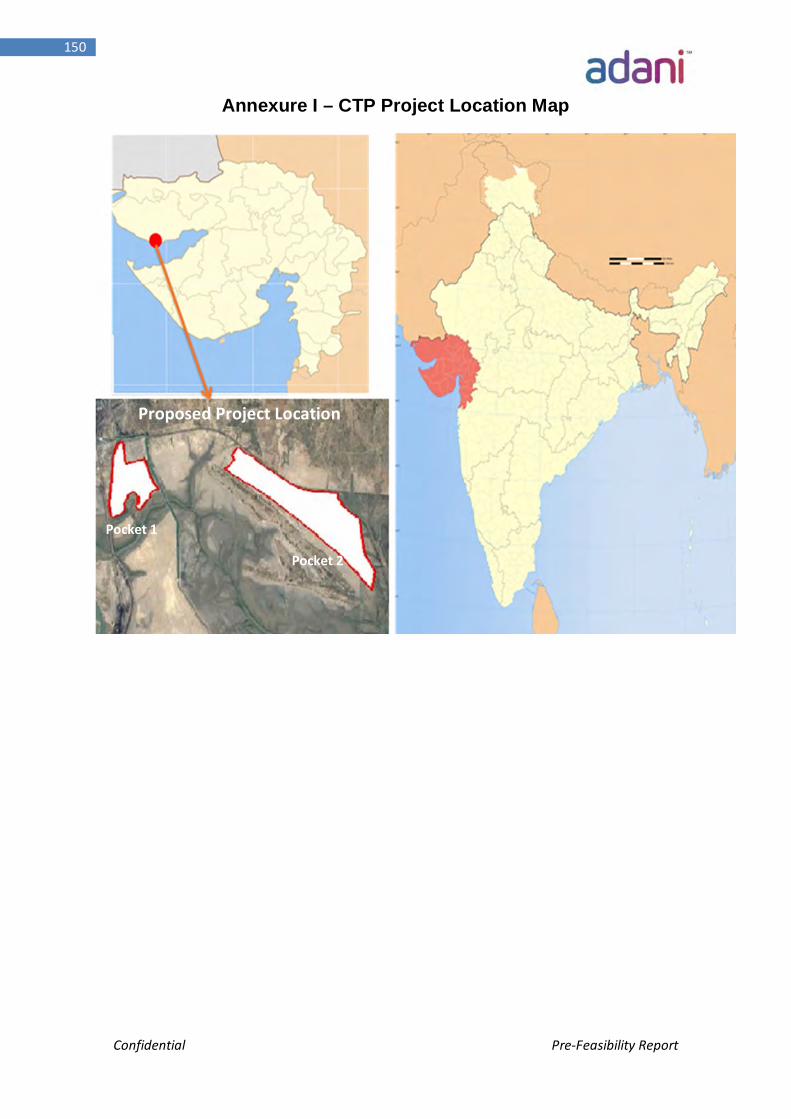
Confidential Pre-Feasibility Report
150
Annexure I – CTP Project Location Map
Proposed Project Location
Pocket 1
Pocket 2
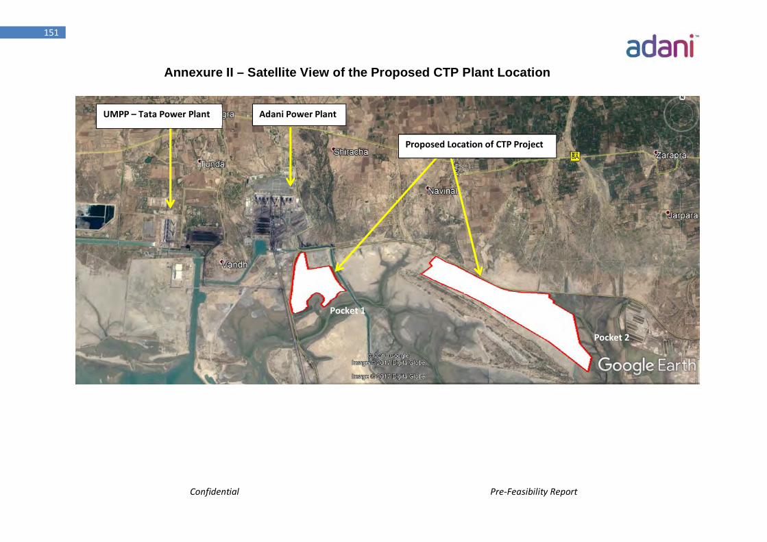
Confidential Pre-Feasibility Report
151
Annexure II – Satellite View of the Proposed CTP Plant Location
Adani Power Plant UMPP – Tata Power Plant
Proposed Location of CTP Project
Pocket 1
Pocket 2
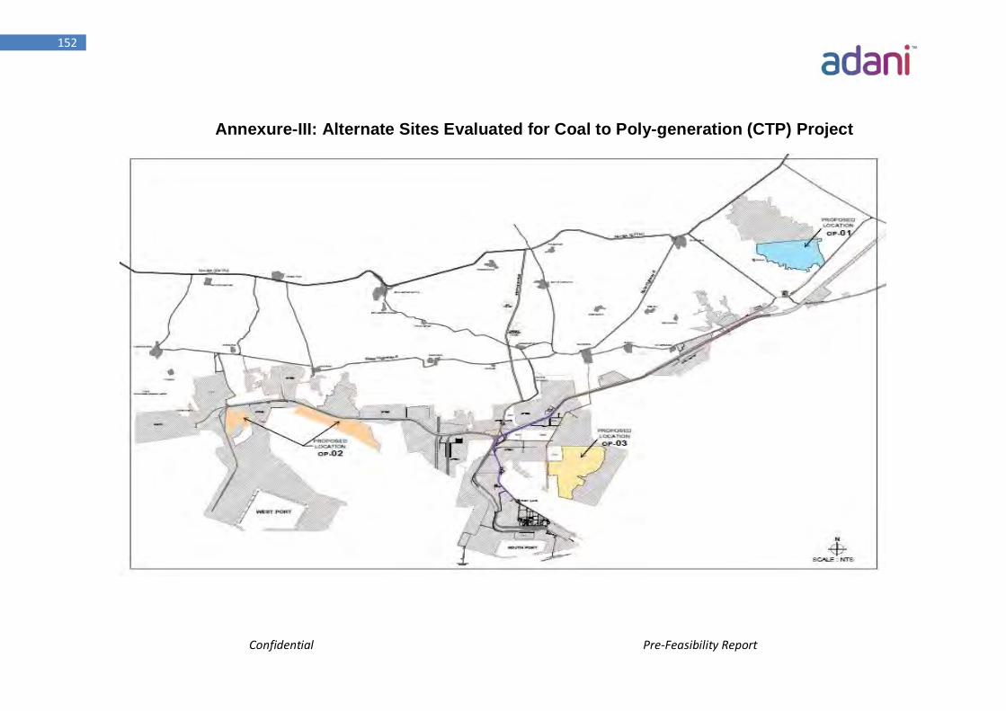
Confidential Pre-Feasibility Report
152
Annexure-III: Alternate Sites Evaluated for Coal to Poly-generation (CTP) Project
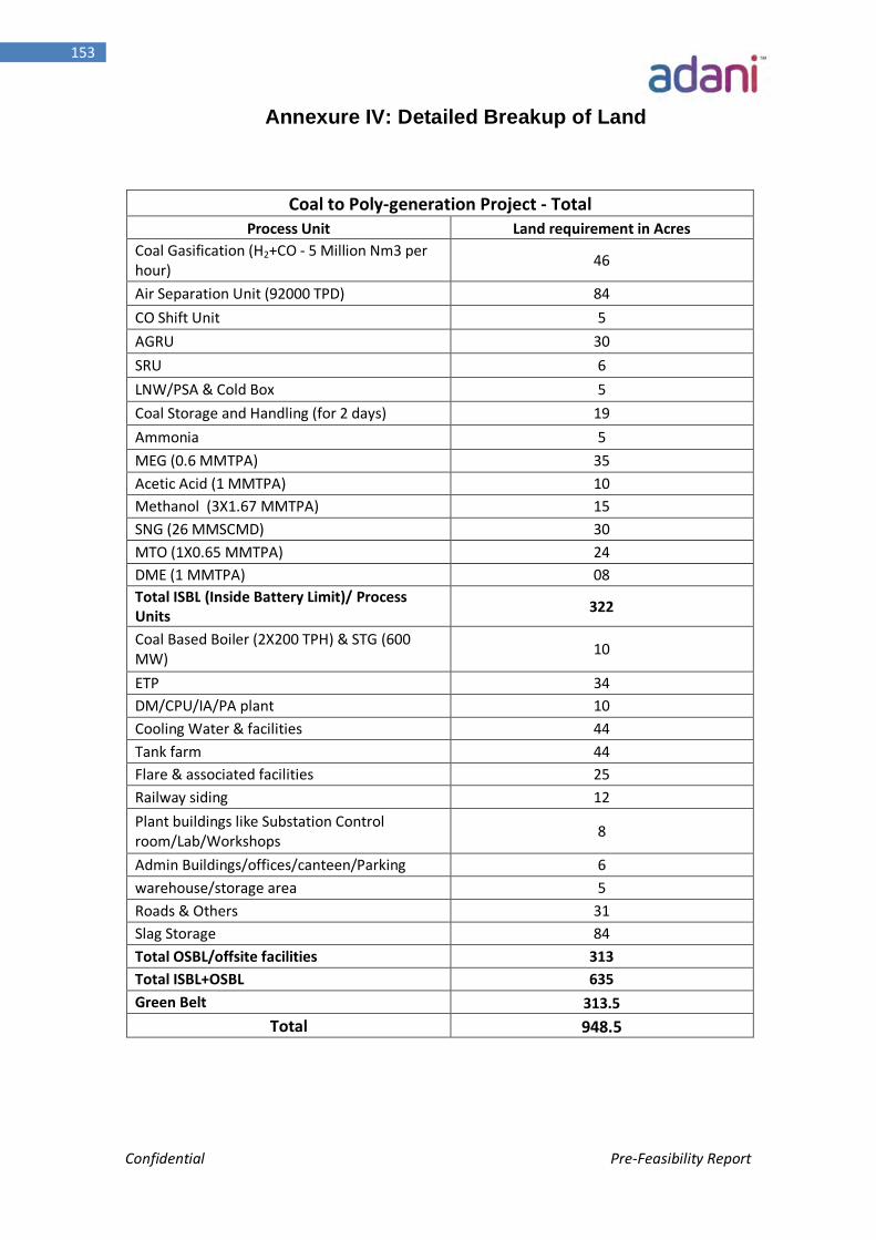
Confidential Pre-Feasibility Report
153
Annexure IV: Detailed Breakup of Land
Coal to Poly-generation Project - Total Process Unit Land requirement in Acres
Coal Gasification (H2+CO - 5 Million Nm3 per hour) 46
Air Separation Unit (92000 TPD) 84 CO Shift Unit 5 AGRU 30 SRU 6 LNW/PSA & Cold Box 5 Coal Storage and Handling (for 2 days) 19 Ammonia 5 MEG (0.6 MMTPA) 35 Acetic Acid (1 MMTPA) 10 Methanol (3X1.67 MMTPA) 15 SNG (26 MMSCMD) 30 MTO (1X0.65 MMTPA) 24 DME (1 MMTPA) 08 Total ISBL (Inside Battery Limit)/ Process Units 322
Coal Based Boiler (2X200 TPH) & STG (600 MW) 10
ETP 34 DM/CPU/IA/PA plant 10 Cooling Water & facilities 44 Tank farm 44 Flare & associated facilities 25 Railway siding 12 Plant buildings like Substation Control room/Lab/Workshops 8
Admin Buildings/offices/canteen/Parking 6 warehouse/storage area 5 Roads & Others 31 Slag Storage 84 Total OSBL/offsite facilities 313 Total ISBL+OSBL 635 Green Belt 313.5
Total 948.5
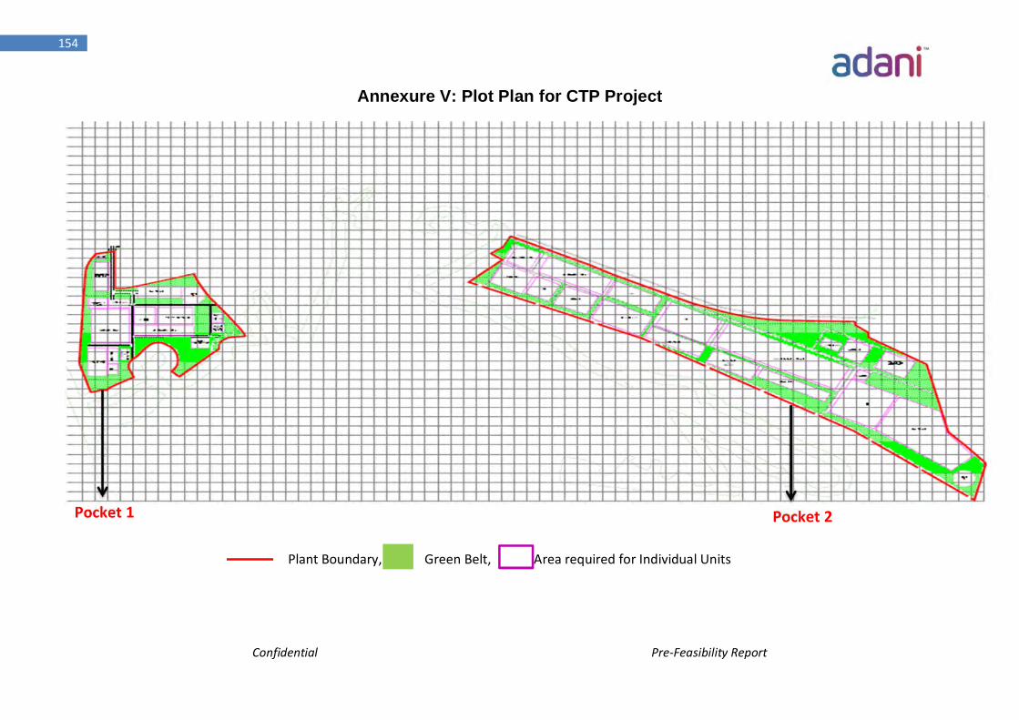
Confidential Pre-Feasibility Report
154
Annexure V: Plot Plan for CTP Project
Plant Boundary, Green Belt, Area required for Individual Units
Pocket 1 Pocket 2
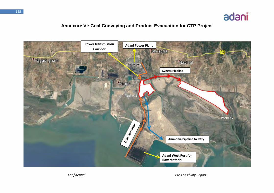
Confidential Pre-Feasibility Report
155
Annexure VI: Coal Conveying and Product Evacuation for CTP Project
Adani West Port for Raw Material
Syngas Pipeline
Ammonia Pipeline to Jetty
Power transmission Corridor
Adani Power Plant
Pocket 1
Pocket 2
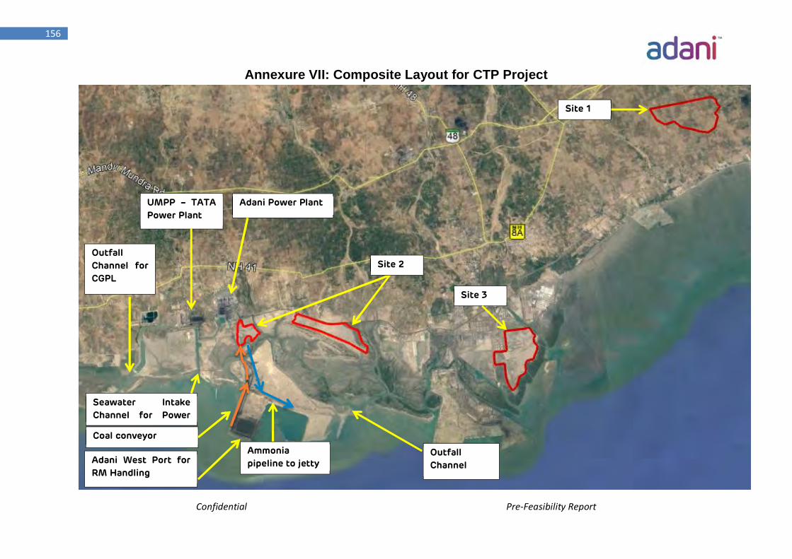
Confidential Pre-Feasibility Report
156
Annexure VII: Composite Layout for CTP Project
Outfall Channel for CGPL
Seawater Intake Channel for Power
Site 1
UMPP – TATA Power Plant
Adani Power Plant
Coal conveyor
Site 3
Site 2
Outfall Channel Adani West Port for
RM Handling
Ammonia pipeline to jetty
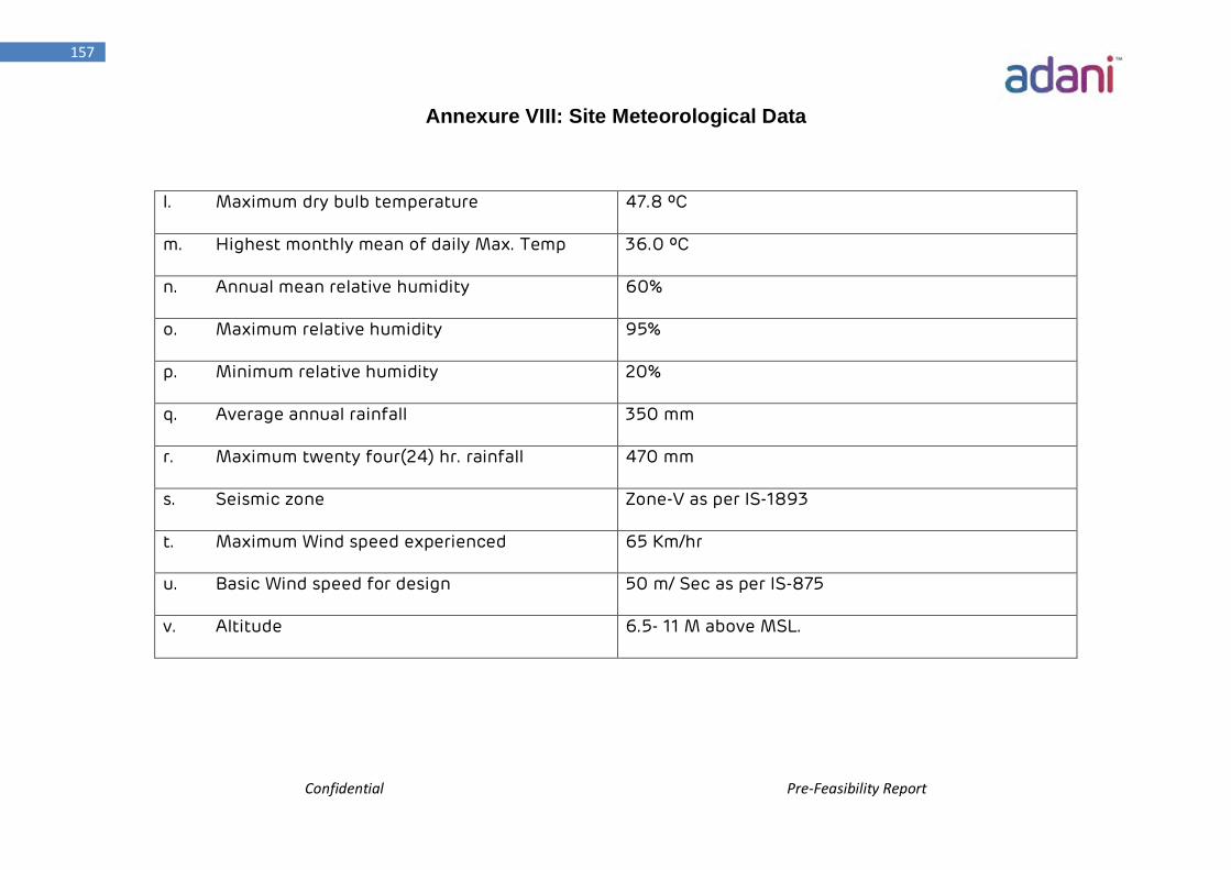
Confidential Pre-Feasibility Report
157
Annexure VIII: Site Meteorological Data
l. Maximum dry bulb temperature 47.8 ºC
m. Highest monthly mean of daily Max. Temp 36.0 ºC
n. Annual mean relative humidity 60%
o. Maximum relative humidity 95%
p. Minimum relative humidity 20%
q. Average annual rainfall 350 mm
r. Maximum twenty four(24) hr. rainfall 470 mm
s. Seismic zone Zone-V as per IS-1893
t. Maximum Wind speed experienced 65 Km/hr
u. Basic Wind speed for design 50 m/ Sec as per IS-875
v. Altitude 6.5- 11 M above MSL.
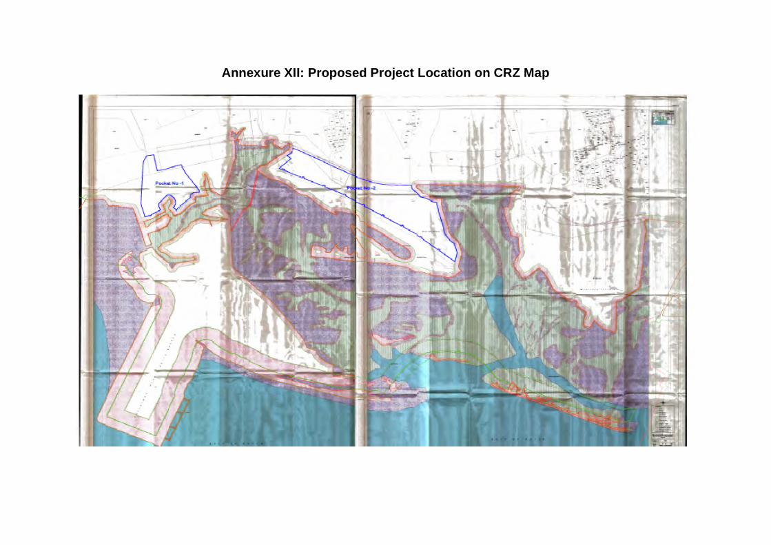
Annexure XII: Proposed Project Location on CRZ Map