pre-planningapps.fcc.gov/edocs_public/attachmatch/da-14-389a2.docx · web viewmany television...
TRANSCRIPT

Response to theFederal Communications Commission for the
Broadcaster Transition Study Solicitation - FCC13R0003
Submitted by:Widelity, Inc.
4031 University DriveFairfax, VA 22030
December 30, 2013

TABLE OF CONTENTS
Table of Contents..............................................................................................................................1
List of Figures and Charts.................................................................................................................4
List of Images...................................................................................................................................5
Acknowledgements...........................................................................................................................6
1.Introduction....................................................................................................................................7
2.Background....................................................................................................................................8
3.Issues Encountered........................................................................................................................9
4.Timing Issues - Planning.............................................................................................................10
4.1 Pre-planning.........................................................................................................................11
4.2 Planning and Initial Steps....................................................................................................11
4.3 Project Management and Equipment Acquisition...............................................................12
5.Tower Modifications....................................................................................................................13
5.1 Overview of the Current Structural Standard “Rev. G”......................................................13
5.2 Tower Analysis....................................................................................................................14
6.National Environmental Policy Act (NEPA) & National Historic Preservation Act (NHPA)....14
7.Antenna Structure Registration (ASR)........................................................................................15
8.Zoning and Permitting.................................................................................................................16
9.CP Application Preparation and Processing................................................................................16
10.Interim Facility Flexibility.........................................................................................................16
11.Building Space...........................................................................................................................18
12.Tower Crews..............................................................................................................................18
12.1 Addressing Tower Crew Shortages...................................................................................19
12.2 Tower Work Requiring Helicopters..................................................................................19
12.3 Tower Work at Remote Sites.............................................................................................19
12.4 Disposal.............................................................................................................................20
13.Broadcast Field Engineers.........................................................................................................20
13.1 Two Types of Broadcast Field Engineer Services.............................................................20
14.RF Engineers..............................................................................................................................21
15.Structural Engineers...................................................................................................................21
16.Transmitters...............................................................................................................................21
16.1 Types of Transmitters: Tube and Solid-State...................................................................22
16.2 Transmitter Retuning.........................................................................................................22
16.3 Transmitter Support...........................................................................................................24
- 1 -

16.4 Transmitter Industry Overview.........................................................................................24
17.Mask Filters...............................................................................................................................24
17.1 Channel 14 Mask Filters....................................................................................................25
18.Transmission lines.....................................................................................................................25
18.1 Types of Transmission Line..............................................................................................25
18.2 Transmission Line Industry Overview..............................................................................26
19.Antennas....................................................................................................................................27
19.1 Types of Antennas: Slotted, Panel and Stacked...............................................................27
19.2 Typical Antenna Lengths...................................................................................................28
19.3 Antenna Reuse...................................................................................................................28
19.3.1 Combiner for shared antenna....................................................................................29
19.4 Antenna Length with Channel Change..............................................................................29
19.5 Antenna Equipment Manufacturing Capacity...................................................................30
20.Tower, Antenna and Site Owner Negotiations..........................................................................31
21.Impacts on Multitenant Towers.................................................................................................32
22.Special Cases.............................................................................................................................32
22.1 DTS....................................................................................................................................32
22.2 Quiet Zones........................................................................................................................33
23.Coverage Verification................................................................................................................33
24.Noncommercial Stations............................................................................................................33
25.MVPDs......................................................................................................................................34
25.1 Over-the-Air Reception.....................................................................................................35
25.2 Non-Broadcast Reception..................................................................................................37
25.3 Channel-Sharing................................................................................................................37
25.4 Notice.................................................................................................................................37
25.5 Issues Specific to DBS Providers......................................................................................37
26.Potential Cost and Time Mitigation Techniques.......................................................................38
27.Proposal for a Reimbursement Contractor.................................................................................39
28.Reimbursement Methodology....................................................................................................40
29.Tax Implications........................................................................................................................40
30.Catalog of Potential Expenses and Estimated Costs..................................................................41
31.Decision Modeling.....................................................................................................................42
32.Sample Case Studies..................................................................................................................44
32.1 Sample Case Study #1.......................................................................................................44
32.2 Sample Case Study #2.......................................................................................................46
- 2 -

32.3 Sample Case Study #3.......................................................................................................48
32.4 Super Complicated Sites: Mount Sutro Case Study #4.....................................................50
33.Conclusions................................................................................................................................53
Appendix A Examples....................................................................................................................54
A.1 Towers................................................................................................................................54
A.2 Transmitters, Filters, Etc.....................................................................................................66
Appendix B Catalog of Potential Expenses and Estimated Costs..................................................70
- 3 -

LIST OF FIGURES AND CHARTS
Figure 1 Consulting Planning Loop................................................................................................13
Figure 2 Standard Transmitter Elements........................................................................................25
Figure 3 Rigid coaxial line section lengths and the channels not supported..................................27
Figure 4 Tower Decision Process Model........................................................................................45
Figure 5 Non-tower Decision Process Model.................................................................................46
Figure 6 Rev.G Decision Drivers...................................................................................................46
Figure 7 Cost Elements Channel 50 to 15......................................................................................48
Figure 8 Cost Estimate Channel 50 to 15.......................................................................................48
Figure 9 Cost Elements Channel 32 to 28......................................................................................50
Figure 10 Cost Estimate Channel 32 to 28.....................................................................................50
Figure 11 Cost Elements Channel 34 to 28....................................................................................52
Figure 12 Cost Estimate Channel 34 to 28.....................................................................................52
Figure 13 Cost Elements Sutro Tower............................................................................................55
Figure 14 Cost Estimate Sutro Tower.............................................................................................55
- 4 -

LIST OF IMAGES
Image 1 Sutro Tower at Mount Sutro, San Francisco, CA.............................................................54
Image 2 Tall tower with top-mounted UHF-VHF antenna stack...................................................57
Image 3 WEKW-TV Tower with DTV top mounted, WKNE(FM) side mounted........................58
Image 4 Sandia Crest, New Mexico...............................................................................................58
Image 5 Sandia Crest, New Mexico...............................................................................................59
Image 6 South Mountain, Phoenix, AZ..........................................................................................59
Image 7 Mount Sutro Tower, San Francisco, CA...........................................................................60
Image 8 Mount Sutro Tower, San Francisco, CA...........................................................................60
Image 9 Empire State Building.......................................................................................................61
Image 10 Empire State Building.....................................................................................................61
Image 11 Candelabra in Tampa, FL...............................................................................................62
Image 12 Candelabra with stacked antennas in Tampa, FL...........................................................62
Image 13 Willis Tower, Chicago, WLS-TV antenna replacement.................................................63
Image 14 Co-located towers...........................................................................................................63
Image 15 Co-located towers...........................................................................................................64
Image 16 Co-located towers, Norfolk, VA.....................................................................................64
Image 17 Winter effects on a broadcast tower...............................................................................65
Image 18 Deer Point, Boise, ID......................................................................................................65
Image 19 UHF Slot antenna lift......................................................................................................66
Image 20 UHF Slot antenna lift with a gin pole.............................................................................66
Image 21 KRCR-TV site on Shasta Bally in winter (Redding, CA)..............................................67
Image 22 Tower base with ice shield..............................................................................................67
Image 23 Candelabra rigged with a gin pole..................................................................................68
Image 24 Candelabra rigged with a gin pole detail........................................................................68
Image 25 Single IOT UHF DTV transmitter..................................................................................69
Image 26 Thomcast (now Comark) dual IOT UHF DTV transmitter............................................69
Image 27 Combiner/filter network for UHF DTV transmitter.......................................................70
Image 28 Exterior cooling unit for liquid cooled transmitter.........................................................70
Image 29 Harris solid state DTV transmitter..................................................................................71
Image 30 Dielectric interior coaxial switch and combiner.............................................................71
Image 31 Harris three IOT UHF DTV transmitter.........................................................................72
Image 32 Dielectric DTV combiner and filter system....................................................................72
- 5 -
ACKNOWLEDGEMENTS
Widelity would like to thank the FCC for their support throughout this project. We would also like to
acknowledge our partners in this endeavor.
We would especially like to thank:
Joseph M. Davis, P.E., President of Chesapeake RF Consultants, LLC
David Cole, President of Cole Appraisal Services, Inc.
- 6 -

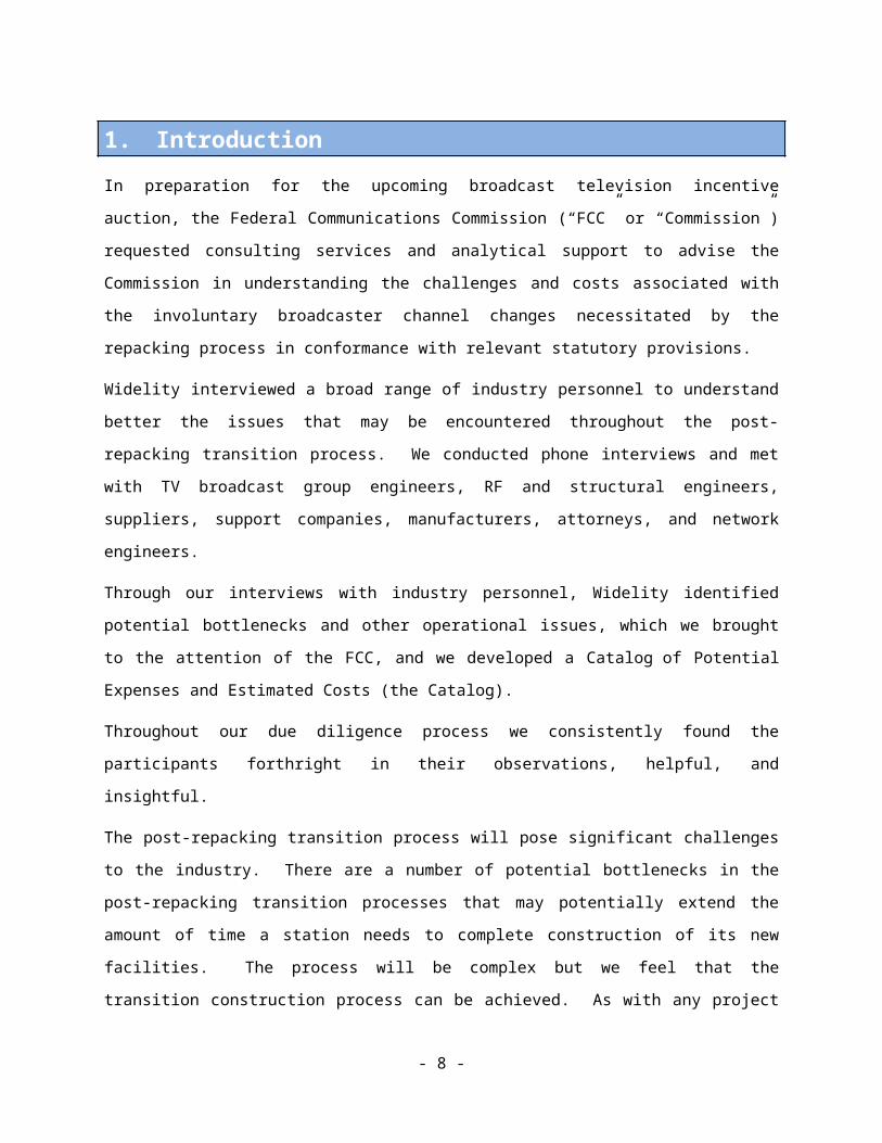
1. IntroductionIn preparation for the upcoming broadcast television incentive auction, the Federal Communications
Commission (“FCC” or “Commission”) requested consulting services and analytical support to advise the
Commission in understanding the challenges and costs associated with the involuntary broadcaster
channel changes necessitated by the repacking process in conformance with relevant statutory provisions.
Widelity interviewed a broad range of industry personnel to understand better the issues that may be
encountered throughout the post-repacking transition process. We conducted phone interviews and met
with TV broadcast group engineers, RF and structural engineers, suppliers, support companies,
manufacturers, attorneys, and network engineers.
Through our interviews with industry personnel, Widelity identified potential bottlenecks and other
operational issues, which we brought to the attention of the FCC, and we developed a Catalog of Potential
Expenses and Estimated Costs (the Catalog).
Throughout our due diligence process we consistently found the participants forthright in their
observations, helpful, and insightful.
The post-repacking transition process will pose significant challenges to the industry. There are a number
of potential bottlenecks in the post-repacking transition processes that may potentially extend the amount
of time a station needs to complete construction of its new facilities. The process will be complex but we
feel that the transition construction process can be achieved. As with any project of this scope, there are
many unknowns but the broadcast industry is very experienced at channel moves and technology
transitions. With cooperation as well as patience, creative problem solving, and guidance from the FCC
and industry groups such as the National Association of Broadcasters, Association of Public Television
Stations, and state broadcast associations, the transition can be achieved with the desired outcomes.
The process of transitioning a station from one channel to another has very distinctive elements that must
be completed for a successful and timely installation. We anticipate that implementing the channel
changes will likely involve some or all of the nine distinct elements listed below.
1. Pre-planning2. RF Engineering3. Structural Engineering4. Negotiating with tower owners5. Permitting6. Negotiation-FCC7. Acquiring equipment/manufacturing
- 7 -

8. Tower Work9. Field Engineering
We will examine each of these elements in this report as each relates to the transition process.
2. BackgroundIn general, demand for TV antennas and transmitters was steady and predictable through the 1990’s and
grew tremendously for the rollout of digital television in the 2000’s. The equipment supply business
encountered a big slowdown after the 2009 digital television (“DTV”) transition. General economic
conditions beginning in 2008 and other industry and governmental factors caused limited station
investment beyond meeting the DTV transition. These difficult conditions prevented stations from
investing heavily in new equipment. There is also virtually no ongoing investment in new antennas and
transmitters. The marketplace has been depressed for several years and existing equipment has not
reached the end of their useful lives. Thus, US demand for antennas and transmission equipment has
stagnated, which in turn has created a downturn for manufacturers. Manufacturers are reluctant to put in
capital to ramp up production without a firm decision as to the amount and timing of repacking. Because
of the drop-off in work, it is also hard to keep talent in the industry. The same situation is found
regarding tower crews skilled at working on tall complex towers, as most jobs now are simply repair and
maintenance issues.
We examined the direct impact of some of the processes based on anticipated work stemming from the
post-repacking transition process. If there are many stations voluntarily taking auction proceeds to go to
VHF from UHF, that could result in significant tower reconfigurations, thus diverting manufacturer and
service provider resources from the stations that are involuntarily repacked. Other secondary impacts on
the scarce resources involve potential site consolidations and maximizations by stations that are not
repacked but have the opportunity due to changed protections. In addition, LPTV and translator stations
being displaced and the analog LPTV sunset in 2015 will further put pressure on scarce resources as
stations require support to make channel moves and to meet DTV transition requirements.
In the DTV transition process, stations knew their channel assignments well in advance and could plan
accordingly. This time, the planning cannot begin in earnest for any station until they find out whether
they will be repacked and are provided their new channel. Some stations may be able to begin partial
planning if their current channel assignment is within the proposed spectrum to be cleared, but will not be
able to have a complete plan until the release of the repacking results. Even with the best-laid plans, there
may be delays due to unforeseen events such as manufacturer defects, wrong parts, incomplete or
incorrect documentation of towers and existing installations, acts of God, and other surprises.
- 8 -
Following is our analysis of the issues based on our interviews with industry personnel.
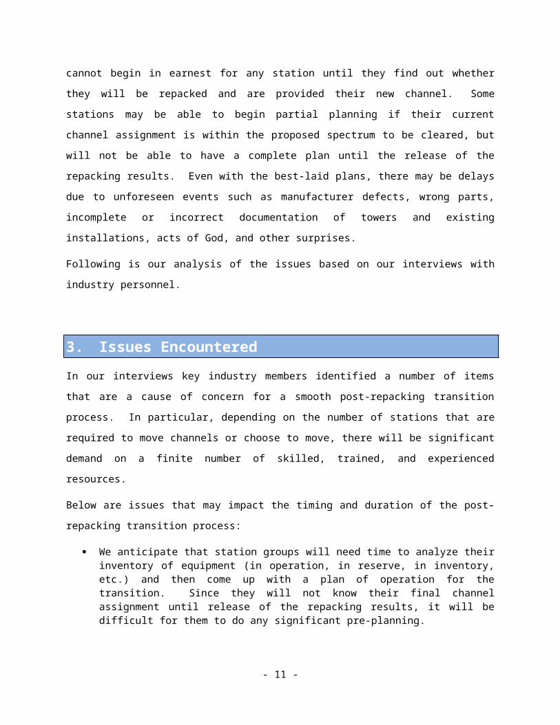
3. Issues Encountered In our interviews key industry members identified a number of items that are a cause of concern for a
smooth post-repacking transition process. In particular, depending on the number of stations that are
required to move channels or choose to move, there will be significant demand on a finite number of
skilled, trained, and experienced resources.
Below are issues that may impact the timing and duration of the post-repacking transition process:
We anticipate that station groups will need time to analyze their inventory of equipment (in operation, in reserve, in inventory, etc.) and then come up with a plan of operation for the transition. Since they will not know their final channel assignment until release of the repacking results, it will be difficult for them to do any significant pre-planning.
Manufacturers and RF Consulting, Structural, and Field Engineers may not be in a position to handle the potential onslaught of requests that will occur once the repacking results come out. A “bunching” of requests immediately after repacking results are released may cause delay in the initial portions of the process.
Multiple iterations may be necessary between the RF Engineer, structural engineer, and manufacturers for an acceptable tower plan prior to the filing for a construction permit. Deadlines for filing for construction permits and stations’ planning periods should take into account these variables.
RF Engineers will have to review channel assignment(s) and work with antenna manufacturers, structural engineers, transmitter manufacturers, and suppliers of mask filters, transmission lines, and combiners to develop the final transmitter-antenna configuration. There are a limited number of RF Engineering resources in the country and these resources will be stretched if many channels require analysis at the same time.
The Electronic Industries Alliance/Telecommunications Industry Association (“EIA/TIA”) RS-222-G “Structural Standards for Antenna Supporting Structures and Antennas” sets minimum standards and industry accepted practices for steel tower structures commonly used for supporting antennas. The most recent revision (Rev. G) is a significant revision that modifies and adds parameters to the analysis. The impact for many towers is that they may require additional structural work or need replacement if antenna or line loading is changed.
There are a limited number of qualified tower crews, no more than 14, capable of working on complex and tall towers. A complex tower is being defined as a very tall towers, (1,000’ or higher) or a tower with a candelabra, or other special conditions. This will potentially be a bottleneck since there is likely to be more work than these crews can handle in a timely fashion.
Some transmitters in use are “orphaned,” meaning the manufacturer is no longer in business or parts are unavailable, making re-tuning of existing equipment impractical. This necessitates that a new transmitter must be installed to operate on the new channel.
- 9 -

The TV antenna manufacturing business has downsized due to lack of demand. Manufacturers can increase production; however, orders must be spread out.
Those sites requiring tower, antenna, or other outside work may have to engage in a permitting process that is highly unpredictable. In addition to permitting, some locations (such as those that are in close proximity to residential neighborhoods) may have to work through community issues for RF analysis and related public concerns.
Many television stations share tower space with other broadcast entities, such as FM radio stations. Tower work required for a channel move will require the adherence to RF safety guidelines, which will likely cause the other tenants to broadcast at reduced power for extended periods. FM stations, as well as other TV stations, will experience power reductions, which will have to be coordinated around critical ratings periods.
There will be timing and deployment implications due to weather and seasonal influences in certain areas. Northern climates will have snow and ice that will prevent tower crews from climbing. At certain times of the year, migratory bird flight paths may impact scheduling and access to towers. If helicopters are needed for an antenna lift, it may be necessary to schedule the installation outside of fire season, as the helicopters used for antenna installations are usually booked during that period. Beyond fire season, helicopter access may be further constrained due to an extensive permitting process in many localities making scheduling difficult.
Whether a single transition date is established or if a phased/regional plan can reasonably be established will impact a station’s timing of the work.
For a phased transition, there is a possibility that a station that is “ready to go” to their new channel assignment may have to wait for a station in an adjacent market to complete their transition. This might cause significant delay and cause some stations to have to operate on reduced power for extended periods.
Negotiations with site and tower owners will add variability to a station transition process. Some stations share tower space, lease land, or share antennas with other stations in the market. These negotiations are unpredictable in length and may cause uncertainty in the timing of the process.
International coordination with Canadian and Mexican regulatory authorities can be time consuming and will add complexity to the process for stations within 400 km (248 miles) of the Canadian border and 275 km (171 miles) of the Mexican border if not addressed in some manner prior to the auction.
Noncommercial stations such as PBS affiliates face specific funding and governance issues. Funding sources and decision makers may be universities and state agencies. The unique governance structure of many noncommercial stations will add approval variability to the process.
4. Timing Issues - PlanningThe following is a list of planning and process issues that may impact the timing of the post-repacking
transition.
- 10 -

4.1 Pre-planning
Prior to receiving their new channel allotments, station groups and individual stations may make
preliminary plans for the post-repacking transition. The internal process will vary in length based on the
number of stations in the group and the internal resources available to address the transition. Some
stations may expect to be repacked to a new channel (such as those close to channel 51), however, many
will not know in advance whether their channel allotment will be changed.
Once the new channel allotments are published, response time for planning and decisions will vary
greatly based on the internal processes of the organization and the complexity of the station’s
requirements. The interval between the release of the repacking results and the engagement of additional
planning resources (RF and Structural Engineers) will have a significant impact on timing.
4.2 Planning and Initial Steps
Upon receiving a new channel allotment, the initial tasks generally involve engaging an RF Consulting
Engineer to review the technical specifications and begin development of transmitting facility parameters.
A few TV groups handle most or all of these steps internally, however, in most cases the RF Consulting
Engineer conducts channel studies, develops antenna parameters, and prepares the engineering portions of
the FCC Form 301 Construction Permit (“CP”) application. Many significant determinations and
decisions must be made before facility parameters can be developed which, in turn, are relevant to
meeting the deadline for filing the CP application. (See Figure 1 Consulting Planning Loop for a view of
the process) Development of antenna and transmission line specifications by the RF Consulting Engineer
begins with an evaluation of the prospective antenna location, with respect to conformance with the new
channel allotment. The effective radiated power (ERP) and antenna directional pattern, if any, are
reviewed to determine what adjustments can be made that comply with FCC procedures (i.e., principal
community coverage, protection to other stations, minimization of coverage loss areas, and expansion
where desired). If applicable, characteristics of an existing broadband antenna on the new channel are
determined by factory data and supplemented with measurements.
For a new antenna, the development of the prospective antenna generally must be coordinated with an
antenna manufacturer. The RF Consulting Engineer’s antenna directional pattern, gain, and beam tilt
goals are reviewed by an antenna manufacturer for practicality and development of an actual antenna
design. While there are certain “catalog” antenna designs, most antennas are custom made for a TV
station’s particular requirements. The antenna manufacturer’s design effort at this point is usually at no
charge for prospective/quotation purposes. This process develops preliminary mechanical size and
loading specifications of the antenna.
- 11 -
Next, the antenna loading (size and weight) data is provided to the Structural Engineer for consideration
in a tower loading analysis. This process can be delayed if the tower requires field “mapping” to
determine existing loading and tower member sizing. For an “overload finding” the tower options are
either to: (1) strengthen the tower (if reasonable); (2) revise antenna/line specifications or other antenna
loading; or (3) consider a replacement tower or alternate site. Some of these options can involve the RF
Consulting Engineer and antenna manufacturer iteratively adjusting the antenna/line specifications to
reduce tower loading.
Figure 1 Consulting Planning Loop
In the case of leased antenna space, negotiations with the tower owner are usually necessary to allow
installation of the intended antenna.
Once the antenna specification and tower loading are finalized, the station is ready to file an application
for a CP, which will accurately describe the intended, practical facility on the new channel. The planning
period required will vary depending on the complexity of the installation. The RF and structural analysis
must be concluded before the CP application can be filed.
4.3 Project Management and Equipment Acquisition
Project management should also begin during the development of the facility parameters in order to
formulate an implementation plan. Beyond the RF planning outlined above associated with the antenna
- 12 -

and tower, a transition plan must be developed and contact established with equipment vendors,
contractors, and other service providers. Determinations must be made regarding possible retuning of
existing transmitter equipment inside the transmission building or whether complete replacement is
necessary, and how to accommodate any needed interim operations. Detailed quotations for equipment
and services must then be obtained. Some stations will need outside assistance with project management
due to insufficient staffing levels to support a major project.
At the acquisition phase, actual orders for antennas and equipment would typically occur following the
grant of the CP. To expedite the acquisition process, stations could obtain quotations from vendors prior
to the grant of the CP; however, ordering equipment in advance of CP grant would be of some risk as
there may be an unanticipated complication in getting the CP, necessitating modified parameters ( i.e.,
interference conflict with another station’s CP application, an international coordination problem, etc.).
5. Tower ModificationsMany towers are 40 to 50 years old and, if not updated recently, will almost certainly require work to
accommodate a change in loading to meet the current structural standard. Work to upgrade the towers
can include structural steel reinforcement and/or guy wire replacement. Older towers may require
significant upgrades as they were designed to previous, less stringent, standards. Additional equipment,
or larger heavier equipment, may cause the tower to need additional reinforcement. In some cases the
tower may need to be replaced.
5.1 Overview of the Current Structural Standard “Rev. G”
Adoption of the most recent tower structural standard, EIA/TIA RS-222-G (“Rev. G”), is a significant
issue that will affect the timing and cost of broadcasters’ relocation to new channel assignments post-
transition.
The most recent revision (Rev. G) adds parameters to the analysis which will impact many towers.
Towers may require additional structural work or need to be replaced if additional equipment will be
installed. The Rev. G standard applies to all steel antenna structures and antenna supporting structures
used to support communications equipment. The new standard reflects new requirements for wind
loading, icing, safety facilities, foundations and seismic considerations. Among other things, Rev. G
includes additional ice and wind loading impacts having significant implications for towers in winter
climates and coastal communities, and introduces classifications based on the operational use of the tower
and surrounding topography. The Rev. G standard has not been adopted ubiquitously by all states,
- 13 -

municipalities, and insurance companies, though a majority require it. Industry sources estimate that 30%
of towers are currently compliant with Rev. G.
All changes to towers, beyond the original design scope, will require compliance review by a Structural
Engineer and may require upgrades and modifications to the tower. Exact kind, one-for-one swaps,
generally do not trigger a new review, but, adding new equipment or change outs to different equipment
types does. In some cases, tower upgrades may not be possible or economically feasible, triggering the
need for a total tower replacement.
5.2 Tower Analysis
Structural analysis of towers to determine compliance with applicable standards could take between 4-6
weeks. Towers without “as built” documentation will require tower mapping by a field crew, which can
take up to 6-10 weeks. Tower modifications can then take 4-6 weeks to get material prepared and another
4-6 weeks to install.
Field crews doing tower mapping and tower modifications may be subject to limited availability and
scheduling issues (see Tower Crews, at Section 12).
Guy wire replacement for large towers can take up to 4 to 6 months just to obtain new guy wires. The
installation can take significant additional time after that. The installation can also be exceptionally long
and difficult due to co-located towers that require interleaved guy wires. (See Image 16)
6. National Environmental Policy Act (NEPA) & National Historic Preservation Act (NHPA)
Occasionally, certain tower modifications trigger NEPA and NHPA (Section 106) review and possibly an
Environmental Assessment (EA) and/or historical or tribal consultation. Conducting the appropriate
study or consultation will add time to any process prior to filing the CP application. As was discovered
during the implementation of the National Telecommunications and Information Administration’s
(“NTIA”) Broadband Technology Opportunities Program (“BTOP”), EAs can be a source of delays for
data gathering analysis. Gathering information and Environmental Assessment Reporting proved to be
one of the single biggest causes of delays.
As an example, a NEPA and/or NHPA screening may be triggered by the following conditions:
Increasing overall height of tower (including antennas & appurtenances by either 10% or 20' (whichever is smaller).
- 14 -

Doing ANY ground disturbance (digging of any kind) that expands the boundaries of leased or owned property surrounding the tower by more than 30 feet in any direction or involves excavation outside these expanded boundaries or outside any existing access or utility easement related to the site.
Pouring significant concrete pads.
Building a new tower.
The tower is located on federal or tribal land, including Bureau of Land Management and US Forestry land.
The tower will be taller than 450 feet above ground level (“AGL”). Changing the tower lighting. Modifying or collocating on a tower that in error has not previously gone through NEPA and/or
NHPA review.
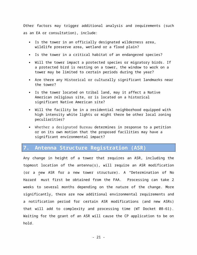
Other factors may trigger additional analysis and requirements (such as an EA or consultation), include:
Is the tower in an officially designated wilderness area, wildlife preserve area, wetland or a flood plain?
Is the tower in a critical habitat of an endangered species?
Will the tower impact a protected species or migratory birds. If a protected bird is nesting on a tower, the window to work on a tower may be limited to certain periods during the year?
Are there any Historical or culturally significant landmarks near the tower?
Is the tower located on tribal land, may it affect a Native American religious site, or is located on a historical significant Native American site?
Will the facility be in a residential neighborhood equipped with high intensity white lights or might there be other local zoning peculiarities?
Whether a designated Bureau determines in response to a petition or on its own motion that the proposed facilities may have a significant environmental impact?
7. Antenna Structure Registration (ASR)Any change in height of a tower that requires an ASR, including the topmost location of the antenna(s),
will require an ASR modification (or a new ASR for a new tower structure). A “Determination of No
Hazard” must first be obtained from the FAA. Processing can take 2 weeks to several months depending
on the nature of the change. More significantly, there are now additional environmental requirements and
a notification period for certain ASR modifications (and new ASRs) that will add to complexity and
processing time (WT Docket 08-61). Waiting for the grant of an ASR will cause the CP application to be
on hold.
- 15 -

8. Zoning and PermittingZoning is usually not an issue for like-antenna swaps. However, there are some sites that are rigorously
constrained and monitored. Zoning and permitting can be a big issue for tower extensions, additional
equipment or replacement of existing equipment. In some cases this process can add significantly to a
timeline. Zoning and permitting issues are usually associated with major metropolitan areas, locations
with sensitive environmental, scenic, or historical considerations, or where there are residential areas in
close proximity to the broadcast location. Timeframes associated with zoning and permitting wary
widely from municipality to municipality.
9. CP Application Preparation and ProcessingFiling procedures for pre-transition (1997) and post-transition (2008) digital facilities established two
basic types of facilities. In the first group, applications were expedited if they did not exceed the allotted
parameters. These conforming applications did not require interference analysis.
The second group of applications for pre-transition and post-transition were those that exceeded their
allotment’s values and thus required additional preparation and processing time for interference analysis.
For post-transition, this involved filing a second application subsequent to a conforming application and
those were accepted and processed after the conforming applications.
If the post-repacking transition process allows for two types of facilities, (1) those that conform to the
new allotment and (2) those that expand (maximize) beyond those values, then, to avoid delay and
uncertainty in preparation of expansion applications, the FCC’s comprehensive application processing
software could be fully developed and released in advance of the announcement of the repacking results.
The software would need to provide interference analysis of all stations impacted by a proposed expanded
(non-conforming) facility. Station groups and RF Consulting Engineers could then ensure proper
installation and become familiar with the software at an early stage. In turn, this would reduce the time
needed for development of proposed antenna configurations and resultant CP applications after release of
the repacking results.
10. Interim Facility FlexibilityDisruption of a TV station’s operation may occur to accommodate a facility modification associated with
a channel change. Television stations avoid experiencing significant off-air periods. Planned service
interruptions are usually limited to no more than several hours during late night or very early morning
hours.
- 16 -

Channel changes can involve antenna replacement, transmission line replacement, and/or certain
transmitter work (re-tuning or replacement). Stations have a number of choices when planning a channel
change. They may choose to install an interim or auxiliary antenna. An interim antenna is a second
station antenna that is installed for a limited period of time and will be removed once the station installs
its new primary antenna. An auxiliary antenna is a permanent second antenna with cutover capabilities to
maintain operations in the event of an outage, replacement, or repair of the primary antenna. To avoid
total cessation of operation during antenna/tower work, it is usually necessary to operate with an interim
facility. This in turn will provide a reduced coverage area due to a lower antenna (side-mount) position
and/or reduced transmitter power output. Power may have to be reduced even further at times to protect
tower workers from excessive exposure to RF electromagnetic field.
Some stations may already have auxiliary backup locations that they can utilize during the post-repacking
transition, but others may have to construct interim facilities. Auxiliary antennas (and transmitters) are
not common at small or medium market stations. The demand for adding interim antennas and
transmitters will put additional stress on tower and installation services. Broadband UHF antennas are in
place on shared towers in a number of markets (i.e., towers owned by Richland or American Tower).
These shared tower owners generally do not provide short-term leases for the use of those antennas, as
owners are generally interested in long-term arrangements. However, the FCC and broadcasters should
still explore ways to leverage these antennas for interim operations.
Depending on how the transition is phased, it could be necessary to operate with an interim facility for an
extended time due to resource scheduling issues (e.g., tower crews, field engineers, relocation of existing
transmitters or antennas, seasonal weather, etc.). For many stations, certain work will have to be done in
advance of and after the channel cutover. Therefore, interim facilities may be needed for operation on
both an old channel prior to the cutover and/or following the cutover on the new channel until such time
that full-power can be achieved.
Stations at shared sites that are not changing channel may require use of an interim facility in order to
accommodate the modifications of a repacked station that is transitioning to its new channel. This may be
necessary to allow antenna repositioning, shared antenna/combiner modifications, and/or tower
modifications.
During the DTV transition there were Commission procedures for dealing with service reduction of the
pre-transition facilities and temporary reduced power operations of post-transition facilities. Those
procedures were tied to certain minimum coverage requirements (i.e., a 6-month STA for reduced power
operation on the post-transition channel could be obtained provided an 85 percent population match of
prior analog and digital service was achieved). Most broadcasters will want to utilize the maximum
- 17 -

practical interim facility as possible, particularly if it is for an extended period; however, in some cases
there may be good reason for a lower power interim operation. By its nature, covering a higher
percentage of the population will require a higher power (and hence more expensive) interim facility.
11. Building SpaceBuilding space at the broadcast location may also impact timing. Because broadcasters recently went
through the DTV transition most of their facilities have been recently updated and likely have sufficient
space, power supply, and HVAC capacity. While building space will not be an issue for stations that
previously hosted full-power analog and digital operations in the same space, it could be a problem where
analog and digital transmissions were at separate sites during the DTV transition or for stations that built
only minimal operations during the DTV transition. In the rare instances where building modifications
are necessary the transition timing could be negatively impacted, especially where ground space is at a
premium, or where there are permitting issues and/or negotiations are required with a landlord.
12. Tower CrewsThere is a consensus in the industry that there are a limited number of qualified crews, no more than 14,
capable of working on complex towers. Many of our interviewees indicated that there are currently only
5 to 10 such crews with the skills for the complex towers. A complex tower is being defined as a very tall
tower (over 1,000’), or a tower with a candelabra or other special conditions (see Image 12). These
towers typically have challenges not usually found on smaller, less complex towers. The height of the
tower combined with the complex nature of the top conditions will require a highly experienced, insured
crew with specialized equipment. The multi-antenna nature of the deployment adds additional
complexity the operation. As a result, broadcasters and tower owners have a specific and limited group of
tower crews that they can rely upon, and will turn to those crews for work. Crews dedicated to the work
generated by the post-repacking transition will also be engaged in their normal fieldwork of maintenance
and repair for existing equipment, including FM antennas. This will provide a further constraint on
resource availability.
There are many more “regional” crews (estimated at 30 to 40) who can handle the smaller (usually under
400’) or simpler (single stick) antennas which may be taller than 400’ but not complex. Some towers are
shorter (mountaintops) or simpler independent of height (single slot antenna on top of a tower).
- 18 -

12.1 Addressing Tower Crew Shortages
While training additional crews may be difficult given the transition timeframe, such opportunities should
still be explored. Once the DTV transition was completed, the demand for tall tower crews dropped off
significantly resulting in fewer experienced personnel staying in the industry. It may be possible to
augment existing crews with personnel who have moved to cell tower work. Due to the limited work
demand on broadcast towers, some have migrated to carrier work and might be recruited back. It is also
possible that there will be experienced crews in Canada who might be recruited to undertake work in the
US. There is also the potential to recruit international (off- shore) tower crew members to augment
existing US crews, though the extent of this possibility is unclear at this early date. International crews
would also be faced with immigration issues, notably they would have to apply and obtain the requisite
work visas.
12.2 Tower Work Requiring Helicopters
In some cases helicopters will be required for tower work, either for lifting n equipment into place or for
building new towers. Where helicopters are used, this can reduce the amount of time a tower crew must
spend on the tower. Helicopters can be hard to schedule due to fire suppression demand. During forest
fire season in the west, most heavy lift helicopters are booked exclusively by federal and state agencies
responsible for the firefighting. This significantly reduces the availability of helicopters and helicopter
crews for tower work.
Some helicopter crews are also dropping the urban construction business, further limiting the inventory of
helicopters. As an example of this issue, the last lift at Willis Tower in Chicago used a helicopter crew
from Canada. Any urban helicopter lift requires extensive planning and permitting. This process can
take a year or more, as it often requires permissions from multiple municipal agencies and extensive
coordination. Urban helicopter lifts often require streets be closed, traffic rerouted, pedestrians restricted
to safe locations, and the clearing of landing areas (including an emergency drop location). The weather
conditions must also cooperate to ensure safe helicopter operating conditions so a specifically scheduled
day may have to be postponed and rescheduled to a safe flying day. Typically, such lifts are limited to
Sunday mornings between sunrise and 8:00 AM.
12.3 Tower Work at Remote Sites
Tower crews working at remote sites will face some unique challenges, such as difficulty getting to the
site, narrow roads, switchbacks, and an inability to get large trucks to the site. Some remote sites also
- 19 -

have very limited ground working areas. This lack of working space makes staging of equipment
particularly difficult and requires extensive coordination for any major installation.
12.4 Disposal
Tower Crews are also generally responsible for cleaning up the site and disposing of the removed
tower/antenna equipment. The scrap value of the equipment often matches the removal, cleanup,
transportation, and disposal cost which can compensate the crews for these activities.
13. Broadcast Field EngineersEach new installation or major modification will need field installation, tuning, and calibration of
transmitter equipment by a broadcast field engineer. Each installation typically takes 3 to 5 days to
complete. In the DTV transition period there were over 100 qualified field engineers working in the
industry. As with tower crews, the demand for this type of work has sharply fallen off since 2009. Many
have retired or changed careers and there are now an estimated 30 such engineers for the US.
Each change of channel requires this tuning and calibration process. If there is a single cutover date,
there may not be enough broadcast field engineers to support the stations as they come online. A phased
implementation will help to ensure that field engineers can be matched to the station’s needs. If the
engineers are also called upon to do FM work, LPTV/translator digital conversions, and other related
tasks, as well as the television retuning process (often one of the last procedures prior to cutover) , there
could be a constraint on the availability of broadcast field engineers.
13.1 Two Types of Broadcast Field Engineer Services
Most broadcast field engineers perform two basic types of services. The first type of service, as described
above, is to install, tune, and calibrate the transmitter equipment. A second function that must be
performed is to conduct an electrical sweep and other testing of antennas (both existing and newly
installed antennas). As there are additional engineers in the industry that can perform antenna testing, we
do not expect that there will be resource issues for antenna sweeps and testing; however, planning and
logistical coordination will be of paramount importance. If broadcasters must rely on the same personnel
to perform both functions, or if the transition cannot be time-phased in a logical sequence by industry
and/or the FCC (i.e., a regional or sequential market basis), these resources may become an issue in
achieving a timely post-repacking transition process.
- 20 -

14. RF EngineersThere are a limited number of RF Engineering resources. Among other things, RF Engineers will have to
review channel assignment(s), work with antenna manufacturers, structural engineers, transmitter
manufacturers and suppliers of mask filters, transmission lines, and combiners to develop the final
transmitter-antenna configuration. A handful of TV station groups have their own RF Engineering
resources and can handle the analysis and coordination in house, including FCC compliance and
application preparation. However, in most cases, stations do not have comprehensive internal resources
and consulting RF Engineers will be needed to meet the analytical, coordination, and FCC compliance
needs of the station. As with some of the other resources, the demand for consulting RF Engineers also
fell following the DTV transition and due in part to general economic conditions. The number of
experienced practitioners has fallen with the downsizing of established firms, career and job changes
(some have gone to work for the FCC), and retirement. We estimate that there are approximately 35
qualified RF consultants, only half of which are positioned to handle more than 5 or 10 stations at a time.
15. Structural EngineersThere are a limited number of structural engineers experienced with broadcast towers. With the impact of
Rev. G (See Section 5) structural engineers will have to review all towers that will require the addition or
change of equipment as a result of the post-repacking transition process. This will have to occur prior to
any designs or plans being finalized and implemented. They will also have to work with antenna
manufacturers, RF Engineers, tower crews, and possibly local jurisdictions. Some towers will have been
well documented and inspected requiring only a structural analysis. Other towers may need a full
inspection to document the current status of the tower (See Section 5.2).
After discussions with key industry experts from the major engineering firms we estimate that a
maximum of 40 structural analyses can be done a month in the United States (this assumes that all firms
operate at peak capacity). If all of the stations turn to the structural engineers at one time, the limited
number of resources may be overwhelmed. Therefore, proper planning and sequencing of the post-
repacking transition process will be of paramount importance.
16. TransmittersTransmitters are the heart of any broadcast operation. The units generally referred to as transmitters are
actually made up of a number of major elements. The exciter accepts the digital program transport stream
from the studio and generates the Advanced Television Systems Committee (“ATSC”) modulated RF
- 21 -
signal at a low power level (less than one Watt). The output of the exciter typically is stepped up to
several hundred Watts in an intermediate power amplifier (“IPA”). In turn, the IPA is fed to the power
amplifier (“PA”) which generates the required power (1 kW to 90 kW). Larger systems have multiple
PA’s with their outputs summed. The PA output is fed into a mask filter, which attenuates out-of-band
emissions to meet the FCC’s requirements. A sample of the mask filter output is typically fed back to the
exciter for adaptive signal processing. The output of the mask filter is fed into the transmission line to the
antenna, or into a combiner system for a shared antenna. Some combiner systems have integrated mask
filters.
16.1 Types of Transmitters: Tube and Solid-State
Solid-state transmitters are employed by VHF stations while UHF transmitters are either tube based or
solid-state. In particular, transmitters having tube-type PA’s are utilized by most high power UHF
stations. The inductive output tube (“IOT”) is liquid-cooled (water/glycol), necessitating an external heat
exchanger and associated plumbing. Each IOT section is capable of 20 kW to 30 kW output power.
Solid-state transmitters associated with UHF stations have notably been for stations that required lower
transmitter output power. Many high power UHF stations have not purchased solid-state transmitters in
the past due to the significant purchase price and efficiency differences when compared to IOT
transmitters. The significant cost and efficiency differences between solid-state and IOT transmitters are
no longer true as solid-state transmitters are now supporting higher powers at a more competitive price
point. Early solid-state devices are now superseded by more efficient devices that save significantly on
the power requirements and thus expenses. Solid-state cooling has traditionally been by forced air,
however, more units are utilizing liquid cooling, particularly for higher power levels.
Some existing transmitters use solid-state components that are no longer supported or widely available.
While there may be a limited parts inventory from the manufacturer or third party vendors, there would
not be enough parts to support wholesale replacement of numerous solid-state transmitters needing new
channels. Solid-state transmitters are employed by VHF stations.
16.2 Transmitter Retuning
While ideally most transmitters can be retuned to a different channel, negating the need for wholesale
transmitter replacement, retuning may not always be practical or cost effective. Both solid-state and IOT
amplifiers have retuning capability, however, depending on the channels involved there may be
“banding” issues (See Figure 2). The feasibility of a transmitter being retuned to a new channel varies
widely. Exciters are generally programmable and wideband. They can easily be reset to a new channel.
Mask filters are not field adjustable to a new channel and must be replaced whenever a broadcaster
- 22 -

changes frequency. This leaves the IPA and PA components, and the coupling between them, as the
major variables for retuning a transmitter.
While some manufacturer’s solid state IPA and PA components are wideband and capable of operation
over the entire band (UHF or high VHF), considerable equipment is currently in place that can be utilized
only over a limited range of channels absent substantial sub-system replacement. In these cases, solid-
state amplifiers (IPA and PA) are divided into sub-bands within the UHF or VHF bands. For instance,
different amplifiers might be utilized for low, mid, and upper portions of the UHF band. The amplifier
can work on a new channel within the same band, however, if the new channel is across to another band,
then the amplifier must be replaced. Within a transmitter, the specific banding schemes can vary between
stages. (See Figure 2 below).
Figure 2 Standard Transmitter Elements
For this example solid-state transmitter, a channel change which spans across one or more sub-bands
above represents “major banding” issues due to the substantial parts replacements necessary. On the
other hand, some transmitter product lines are capable of changing channel over a wide range with
minimal IPA and PA parts requiring replacement and are considered to have only “minor banding” issues.
IOT amplifiers are broadband and can be retuned to a new channel. There are banded coupling
components on the input and output stages of an IOT amplifier that may need replacement for a new
channel. The IPA stage of an IOT transmitter is solid-state and faces the same potential “banding” issues
for solid-state transmitters as previously described.
- 23 -

16.3 Transmitter Support
Manufacturer support is critical for determining whether a transmitter can be retuned to the new channel
and providing parts. The actual number of existing transmitters that can be retuned is not known.
Additional study would be useful to understand the precise functionality of transmitters currently
deployed in the industry. The principal concern is over support for equipment currently in use which is
orphaned or otherwise has limited support issues due to the unavailability of solid-state components.
16.4 Transmitter Industry Overview
Recently there have been many changes in transmitter manufacturers, in part due to the industry
slowdown since the DTV transition. Harris Broadcast has been spun off from its parent company and
while it has incurred some downsizing, it is still the dominant supplier to date. Comark has undergone
several ownership changes in recent years. Axcera went bankrupt and there are concerns over ongoing
support for its product lines. Acrodyne (acquired early in the DTV transition by Sinclair) is no longer
manufacturing transmitters, but is providing service/support.
Rohde & Schwarz (who makes solid-state transmitters exclusively) has a large international market share.
They supplied all of the Qualcomm Media FLO transmitters (in use for just a few years) and those are
being repurposed by TV broadcasters, which increases the company’s familiarity with US broadcasters.
Along with Harris and Comark, Larcan, headquartered in Ontario, Canada, is also producing solid-state
UHF and VHF transmitters as well as IOT UHF transmitters. There are several other manufacturers that
supply lower power only products who might play a role in interim facility installations.
Both Harris and Rohde & Schwarz have indicated that they do not expect manufacturing capacity
problems and are prepared to meet the needs of the industry. Comark has indicated that they are
expanding, but that they have a limit to their production capacity. We do not anticipate that there will be
problems acquiring new transmitters if the process of ordering equipment is orderly and broadcast
stations order equipment as early as possible. If broadcasters wait until late in the process it will cause
orders and manufacturing capacity to be “bunched” and could cause delivery delays.
17. Mask FiltersApplied at the transmitter’s output, the mask filter attenuates out-of-band emissions to meet the FCC’s
requirements for signal suppression on the adjacent channels. A new mask filter is always required for a
channel change. Principal suppliers are Dielectric, ERI (Passive Power), Myat, MCI, and RFS. While
- 24 -

each filter is custom made according to the channel and to complement the particular transmitter,
obtaining mask filters is not expected to be an issue based on our conversations with manufacturers.
17.1 Channel 14 Mask Filters
Additional emission filtering is required for assignments involving Channel 14. The Channel 14
spectrum is immediately adjacent to UHF Land Mobile Radio (“LMR”) allocations where there is no
guard band. Television stations on Channel 14 require additional planning to identify nearby LMR
operations, substantially more stringent filtering, and considerable time for tune up and interference
mitigation. Further, the introduction of vertical polarization on Channel 14 is more challenging since
LMR antennas are vertically polarized (Channel 14 stations might not be able to enjoy the advantages
provided by adding a vertically polarized component). Special filtering may also be required for other
channels depending on the final repacked band plan, and possibly with respect to existing “T-Band” LMR
operations (certain Channel 14-20 reservations that exist for LMR).
18. Transmission linesTransmission line connects the transmitter (mask filter) or combiner output to the antenna, running from
the equipment building up the tower to the antenna. These are copper, coaxial in nature, typically rigid,
and in uniform, fixed lengths of approximately 20 feet. Exact section lengths are determined by the
channel (frequency) and are specified by the RF Engineer to minimize reflection buildup from the section
flange interval of the rigid line, which would otherwise degrade performance. The transmission line may
have to be replaced depending on whether the new channel is prohibited by the existing line section
length (See Figure 3).
18.1 Types of Transmission Line
Common section lengths are 20 feet, 19.75 feet, and 19.5 feet. Figure 3 provides a chart of section
lengths and the channels that are prohibited for each length (from Dielectric catalog).
- 25 -

Figure 3 Rigid coaxial line section lengths and the channels not supported.
To use Figure 3 above, determine the channel to research, if the channel is listed next to a line section
length then that line length CANNOT be used for that channel/frequency. For example, channel 42 will
require a line section lengths of 19 ½’ as it is listed as a non-supported length for 20’ and 19 ¾’.
Similarly, Channel 22 CANNOT use 19 ¾’ but it can use 20’ and 19 1/2’.
The prohibited line lengths outlined in Figure 3 are principally an issue for lines that have been in use to
feed a single-station antenna. For shared antennas, transmission line is usually “broadbanded” by making
minor, non-repeating changes to the section lengths, designed for the channels involved. An alternate
channel lineup for a broadband system could be possible without needing to change the transmission line,
however, an engineering review and field measurements would be needed to determine the suitability of
the existing transmission line.
Lower power and some medium power stations may use flexible line, which is corrugated and fabricated
in a single run. This may reduce the cost of line installation due the easier installation procedures. There
are no flange reflection issues with this type of line.
18.2 Transmission Line Industry Overview
Manufacturers typically obtain copper from overseas, principally from China and Germany. To meet a
high demand, transmission line manufacturers recommended that orders be consolidated or otherwise
coordinated to avoid piecemeal jobs and to allow uniform production.
- 26 -

19. AntennasA television station’s transmitting antenna must be well elevated to serve a wide area, due to the line-of-
sight nature of VHF and UHF propagation. The antenna is typically top-mounted on a tall tower structure
or on a shorter tower at mountaintop locations. At shared sites, some stations must side-mount their
antennas along the upper portion of a tower, however that is a less desirable configuration due to pattern
distortion effects of the tower structure. US television stations generally use single-station antennas,
which are capable of transmitting a single channel and must be replaced to transmit a new channel.
Antennas capable of carrying multiple channels are generally employed by multiple stations that share a
single “broadband” antenna. (See Image 11 and Image 19).
19.1 Types of Antennas: Slotted, Panel and Stacked
Slotted cylinder antennas have long been the dominant type of deployed antenna for UHF channels. They
are cylindrical with openings (slots) cut in them that will radiate the desired frequency. Slotted cylinder
antennas typically support one television channel (6 MHz of spectrum) and are not retunable. Therefore,
they must be replaced when a station moves to a different channel assignment.
A very small percentage of slot antennas can operate satisfactorily on the adjacent channel. During the
DTV transition, some stations that had analog and digital assignments on first-adjacent channels obtained
dual-channel slot antennas for shared analog and digital use (i.e., analog Ch. 26 and digital Ch. 27).
A panel antenna is generally employed for operation over multiple 6 MHz channels and is considered
broadband (also sometimes referred to as a “broadband antenna”). UHF stations that share an antenna
typically employ a panel antenna system made up of dozens of panel elements. Each individual panel is
about 3 feet high and 1.5 feet wide. Multiple panels are stacked vertically to achieve the desired gain and
keep individual panel power levels reasonable. For non-directional operation, five (sometimes four)
panels are arranged at a single level pointing out at uniform intervals. (See top of Image 3).
A typical UHF high power panel antenna will consist of five stacks of 12 panels arranged on the
perimeter of a lattice support (five panels around, 12 high) requiring 72 panels total. The power is
distributed to the panels via a cascading series of power dividers and flexible coaxial transmission line
segments, situated within or underneath the lattice supporting spine. Directional patterns may be created
by varying the amount of power to each stack and/or varying the number of panels in each stack.
UHF panel antennas are optimized for a portion of the UHF band, usually around 20 channels in the
upper portion of the band (Ch. 30’s and 40’s) due to the significant percentage change in frequency that
occurs over the whole band. It is a bigger challenge to include the lowest part of the UHF band since
- 27 -

percentage-wise, a span of Channels 14 to 20 (470 to 512 MHz) is greater than Channels 30 to 36 (566 to
608 MHz). Thus, use of an existing broadband antenna over a new channel configuration may be outside
the capability of the current antenna.
Panel antennas are also utilized in the VHF band and can be shared. Each individual panel is much larger
due to the lower frequency (longer wavelength). Accordingly, the lattice structure supporting the panels
has a larger corresponding cross-section size. Fewer panels are needed since VHF power levels are
lower. These panel antennas should be useful over the entire range of high VHF (Ch. 7-13). Cylindrical
top-mount high VHF antennas are often employed for single channel applications, which are not capable
of operating on a new channel. Older high VHF installations might employ a “bat wing” antenna
(multiple radiating elements vertically aligned on a pole) that are useful over several channels.
Customarily operating with horizontal polarization, the addition of a vertical polarized component (“V-
pol”) has grown rapidly for antennas ordered within the last 5 years or so, which helps overcome some
reception issues and aids mobile DTV reception. However, this increases the weight, increases the cost of
the antenna by as much as 25%, and generally requires additional transmitter power.
Two antennas can also be stacked on top of one another (See the leftmost antenna arm in Image 12). If
antennas are stacked, the bottom antenna must be significantly strengthened to support the weight and
wind loads of the top antenna. This may double the cost of the bottom antenna and significantly increase
the weight on the tower, raising the possibility of structural modifications to accommodate antenna
replacement.
19.2 Typical Antenna Lengths
Typical antenna lengths for full power stations are 40 to 60 feet, weighing 2,000 to 10,000 pounds for slot
antennas and 10,000 to 40,000 pounds for a shared panel antenna. Total lengths for stacked top-mount
antennas are typically 90 to 120 feet and weigh 30,000 to 55,000 pounds.
Antenna systems for UHF Class A stations are smaller and lighter due to the lower power levels involved
(15 kW maximum ERP for digital UHF). These are generally side-mounted aluminum slot antennas with
lengths of 20 to 40 feet and weighing several hundred pounds. Some utilize panel antennas, again in
lighter-weight and side mount versions. High VHF Class A stations (3 kW maximum digital ERP)
typically also employ lightweight/side mounted antennas.
19.3 Antenna Reuse
In order to consider whether an antenna can be used on an alternate channel, original factory data is
necessary to determine the antenna’s gain, directional characteristics, and beam tilt on the new channel.
- 28 -

On-site antenna “sweep” measurements by a field engineer will also be necessary to ascertain whether
certain performance goals are met.
19.3.1 Combiner for shared antenna
For shared antennas, a combiner is placed in the equipment building to accept the power output from all
of the transmitters (on different channels) to feed a common transmission line up the tower to the antenna.
Combiners are custom designed based on the specific frequencies and power levels in use. An alternate
channel arrangement will require modification or replacement of the combiner (in whole or in part,
depending on the particulars).
19.4 Antenna Length with Channel Change
In our interviews, concerns were raised regarding the length of an antenna increasing with a downward
change in channel, as the increased length may extend tower height above FAA and/or local zoning
limits. For a lower channel number, a replacement antenna having the same gain is physically longer due
to the longer wavelength associated with the lower frequency. An antenna having the same length would
have lower gain on the new channel, thus requiring more transmitter power in order to maintain the same
effective radiated power (ERP).
Development of the prior allotment tables (1997 pre-DTV transition and 2008 post-DTV transition) were
based on replication principles that included use of the so-called “dipole factor” on UHF channels. The
dipole factor is an adjustment in ERP to compensate for the slightly higher signal strength requirements
for higher-numbered UHF channels. If the dipole factor is employed in the same manner for replication
of stations changing channel, it should compensate for the use of a shorter antenna without an increase in
transmitter power.
For example, in the case of a 1000 kW ERP station on Channel 50 using a 26-bay slot non-directional
antenna, basic manufacturer “catalog” data shows that the antenna’s length is 39.8 feet and the gain is
13.71 dBd. The power to the antenna would be 42.56 kW to achieve 1000 kW ERP. For a prospective
change to Channel 20, an antenna having the same gain would be 53.2 feet long and therefore potentially
require approval for an increase in overall structure height. However, application of the dipole factor
means that 545.8 kW ERP on Channel 20 would replicate the 1000 kW ERP facility on Channel 50. To
avoid an increase in antenna length, an 18-bay slot antenna could be employed on Channel 20, which is
37.7 feet long and two feet shorter than the Channel 50 antenna. The 18-bay antenna’s gain is 12.04 dBd
and would require 34.12 kW power to the antenna to achieve the replication 545.8 kW ERP. This
example actually shows a decrease in transmitter power despite the shorter, lower gain antenna.
- 29 -

Thus, for replication purposes, there should generally be no issue with transmitter capacity for the use of a
shorter antenna length brought about by use of a lower-numbered UHF channel. The issue could arise
should the station be able to expand beyond the allotted replication ERP or if different procedures are
employed for determining re-packed ERP levels. In the reverse direction however, should a UHF station
be re-packed to a higher-numbered UHF channel, then there could be issues with needing more
transmitter power for an equivalent-length antenna.
The dipole factor was not employed on VHF channels for prior digital allotment tables. For continuation
of this procedure, no change in the ERP would result for replication of the service contour location during
repacking from one high VHF channel to another high VHF channel. Typical top-mount high VHF
antenna lengths vary by frequency with the length of an antenna increasing with a downward change in
channel. For example, manufacturer “catalog” data shows an antenna having a power gain of 12 being
64.4 feet long on Channel 13 and 75.9 feet long on Channel 7. If a longer antenna cannot be
accommodated due to airspace, local zoning, or structural issues, then a shorter antenna having lower gain
would be needed. This will require more transmitter power to achieve the original ERP. A new
transmitter may be needed if the new power level is beyond the capacity of the existing transmitter. This
solution is not as expensive as it would be for UHF because high VHF transmitters operate at a much
lower power.
A minor change to the antenna’s radiation center elevation may result from a change in antenna length,
depending on the final configuration. This in turn may trigger a commensurate change in power. For
instance an increase in antenna radiation center height could require a corresponding decrease in power.
The exact change in power would be determined by the procedures adopted by the FCC for
implementation of the new channel, and is not expected to have a significant impact on transition timing
or cost.
19.5 Antenna Equipment Manufacturing Capacity
During the course of our work, SPX Corporation announced that it was closing its subsidiary Dielectric.
Dielectric is a major supplier of antennas, transmission lines, and filters. 62.7% of existing full power TV
stations have Dielectric antennas. In our estimation, they provide 90% to 95% of the combined panel
antennas. Dielectric has principally been a supplier to US customers. They carried the weight of the
supply and manufacturing for the US television broadcasting industry. They have been the primary
supplier for complicated sites and have extreme brand loyalty from television broadcasters. On June 18th
Sinclair Broadcast Group acquired Dielectric, returning it to full operation. Initial discussions with
Dielectric indicate that they will be resuming business as usual quickly with a full product line. In
- 30 -

addition, they anticipate that they will continue with R&D for new products and improvements. Along
with the other major suppliers; ERI (US), Jampro (US), RFS (AU), and Kathrein (EU), we do not
anticipate major bottlenecks for television antenna supply.
ERI is a major US supplier of TV antennas, transmission, line and tall tower structures. They have
extensive US facilities and indicate that they are prepared to step up to meet the needs of the transition
process as well.
In our discussions with antenna suppliers, they all stressed the need to “smooth out” the ordering process.
If the process of ordering equipment and materials is orderly, manufacturers can effectively schedule
production, delivery, and installation of antennas. If the orders are bunched where everyone is trying to
acquire the same equipment at the same time, there will be delays and difficulty scheduling the work.
In our discussions with manufacturers and suppliers they all were confident that they could increase
output to meet the demands of their customers and clients. They all were expecting to have to provide
additional services and support to broadcasters to meet the needs of the post-repacking transition
timelines. Until demand increases from the repacking process, US TV antenna manufacturing capacity
will likely remain at the current levels.
20. Tower, Antenna and Site Owner NegotiationsAn estimated 15% to 20% of stations lease tower space for their antennas from other broadcasters
(including stations in the same market) or an independent third party (American Tower, Richland, and
building owners for rooftop structures). Stations making antenna changes usually have to negotiate with
the tower owner or the site owner to replace the antenna with a different size/model antenna. They may
also have to negotiate for more ground space or space in the equipment building , and in extreme cases
for rights to use a new tower. Often lease agreements may include the process by which such site
modifications are made, such as notifications to other tenants, and outline who must bear the costs when
making a tower modification. If contractual changes to a lease agreement are required to accommodate a
channel change, such negotiations can potentially delay the planning and decision-making timeline for
stations and station groups.
There are also some instances where a broadcaster does not own its antenna. In those cases, the tower
owner also provides a broadband antenna and combiner, which can be shared by multiple stations. (i.e.,
Richland or American Tower). Alternately, multiple stations may reach their own in-market sharing
arrangements. These relationships can add difficulty as multiple stations must now be involved in the
coordination process, regardless of whether every station is changing channel.
- 31 -

21. Impacts on Multitenant Towers Many towers serve multiple television broadcasters. Additionally, antennas for other services such as FM
stations, emergency services, wireless/cellular providers, and microwave service providers may all be
present at different locations on a tower. Depending on the configuration, and the RF power levels, work
required by a station may have significant impact on the other entities. For example, FM antennas may
block access to top mounted television antennas requiring temporary removal of portions of the FM
antennas. Coordination will be required to remove them and possibly provide temporary antennas during
the work. Ratings are always an issue in FM and TV broadcasters. Crews must work around the ratings
“book,” which will require extensive coordination between television and radio broadcasters.
In some cases, an antenna which is no longer in use will need to be removed to complete the transition
process, and in rare cases, FM antennas may require permanent relocation.
Other tenants on the tower will also be impacted by the post-repacking transition process in terms of
requiring lower power operations (sometimes from an auxiliary location) during periods when tower
crews are working on the equipment modifications and replacement in order to comply with RF
electromagnetic field exposure limits.
Agreements between broadcasting entities (television and radio) co-located on a tower usually allow for
reasonable periods of lower power operations to accommodate safe working conditions and the
provisioning of tower rigging equipment, particularly at sites owned by third parties. However, work
may be limited to certain hours during the day or to overnight periods, which could slow the transition
and increase costs.
22. Special Cases
22.1 DTS
A handful of stations employ a distributed transmission system (“DTS”), where a contiguous service area
is created by multiple transmitter sites with all transmitters operating on the same channel. These are
usually a mix of high and low power operations. A channel change for a DTS operation would involve
the same antenna/line/transmitter issues discussed herein, except repeated for each site.
Additionally, the RF plan will need to consider the degree of signal overlap between adjacent DTS sites.
DTS operations can generally be placed into one of two groups, depending on whether there is terrain
blockage between the sites. The first group compromises of DTS facilities that have signal overlap, but
little or no terrain blockage. For these type of DTS facilities a more critical design is necessary to set
- 32 -

exact power levels, signal synchronization, and antenna directional and elevation patterns, so that mutual
interference between the sites will be minimized. Field adjustment of signal timing will also be needed.
For these reasons, this first group of DTS facilities will take longer to develop on an alternate channel.
The second group of DTS facilities involves sites that serve regions that are terrain-blocked from each
other. In this case, the design is less stringent and time intensive.
22.2 Quiet Zones
Other special cases could involve stations that are near the Table Mountain Radio Receiving Zone
(Boulder County, CO), Radio Astronomy “quiet zones” (e.g. Greenbank, WV and Arecibo, PR), and
various FCC monitoring stations. Directional antennas may be needed, and in extreme cases, a
cancellation antenna could be necessary to protect these facilities. Coordination and implementation time
are involved in these cases, making these sites more expensive to deploy.
23. Coverage VerificationHistorically, most stations have relied on informal staff and viewer reports to confirm coverage. As
stations have been modified over the years (and built out their digital facilities), stations expect to receive
calls from the viewers who have reception problems. These reports are monitored to provide insights into
issues regarding any problematic locations or type of receive antenna.
Some stations and station groups routinely conduct field measurements to ascertain post-construction
performance. These range from station engineering personnel making spot checks or a TV group’s
corporate measurement van documenting signal strength at numerous locations, to commissioning a
rigorous field strength study by a third party to conduct measurements at grid points and along radials
from the antenna site.
All interviewees indicated an in-depth field study would be conducted if a problem was suspected,
something that may not be realized until after the station commences final operation on its new channel.
Coverage verification is a specialized skill set and there are limited resources that can be dedicated to this
process. Should many stations require rigorous field measurements at the same time resources will be
constrained.
24. Noncommercial StationsNoncommercial television broadcast stations (such as PBS affiliates) face unique challenges that in many
cases are far removed from the “mainstream” thought process for the procurement and installation of
equipment required for the post-repacking transition process.
- 33 -

Noncommercial stations are unique in their structure and their requirements. They have four basic
organizational structures:
1. Community/Non-profit organization licensees;2. State/local licensees; 3. Public and private universities; and4. School boards.
The multiple types of organizations cause specific challenges for noncommercial stations facing channel
moves. Procurement processes of the stations to obtain equipment and services may take significant time.
While community licensees might be able to react faster, the remainder involve state, university, or local
processes which may require state legislative approval and can be slow moving.
Some stations have bought equipment through specific grants. Taking that equipment out of service can
be difficult due to the stipulations in the grant agreements. In many cases the equipment must be kept on
hand whether it is in use or not and will increase station costs for, among other things, storage, insurance,
and facilities. Additionally, stations may not have the in-house capabilities to manage the equipment
procurement process, RFP creation, legal agreements, state procurement processes, and engineering.
Because of resource and financial constraints, many noncommercial stations will likely need a larger
upfront reimbursement payment since their funding structure(s) may not be able to support the significant
cash flow requirements of a channel change. Additionally, a number of the towers owned by
noncommercial stations are over 40 years old. As a result, the Rev. G issue (See Section 5) will certainly
arise as noncommercial stations examine the structural worthiness of their towers.
25. MVPDsA Multichannel Video Programming Distributor (MVPD) is a service provider delivering video
programming services, usually for a subscription fee. MVPDs include cable operators and direct-
broadcast satellite (DBS) providers. Because MVPDs deliver broadcast signals to their subscribers, most
MVPDs will be affected by the repacking process, although generally the magnitude of the impact will be
much smaller than on repacked broadcasters.
MVPDs receive broadcast signals in one of two ways, and the impact of the broadcast transition will be
different depending on the method of reception. First, some systems rely on receive antennas to pick up
broadcast signals over-the-air (“OTA”). Second, many MVPDs also receive the signal via a non-
broadcast source (typically fiber, microwave, etc.) for distribution. Once the MVPD has captured the
broadcast signal at these “head-end” facilities (regardless of reception method), MVPDs then convert the
signal in order to distribute it over their cable or satellite system. Regardless of the type of receive
- 34 -

facilities, MVPDs generally prefer a transition period of dual operation (broadcasting on the old and new
channels simultaneously). A single changeover will require careful coordination and may induce
manpower shortages for technicians as they may be required to reset receive equipment in multiple
headend locations in a market. A hard cut-over by the broadcaster is expected to result in a temporary
lapse of service for some MVPDs as they execute their own reconfiguration and work through any issues
on the new channel.
25.1 Over-the-Air Reception
As repacked broadcasters transition to their new channels, MVPDs that rely on OTA signals may
experience a number of transition related issues. RF engineering studies may be required to estimate the
receive strength of the new station assignments, the potential for incoming interference on the new
channel, and the capabilities of the current equipment. Based on the study results, an MVPD may need to
retune or replace its receive antennas, depending on the type of equipment currently in place. Some
receive antennas are broadband (all-UHF or all-Hi-VHF) and will not require retuning or replacement.
This is particularly common for head-ends or receive locations within or near the metro areas. MVPDs
with broadband antennas will, generally, not need to do anything to their deployed antennas as they
should be able to receive the channels in their new assignments.
Other receive antennas are channel-specific (sometimes referred to as “cut-to-channel”) and use
directivity to maximize desired channel signal strength and minimize interference from other stations.
Antennas that are cut-to-channel assure the best OTA reception (signal quality is improved this way for
remote signals). Channel-specific antennas will need to be replaced for a new channel assignment. For
new antennas, new coaxial cable may also be required.
Changes in receive antennas may trigger the need for tower studies and/or tower upgrades. This is
because when the MVPD receive antenna size increases with a reduction in channel (frequency) in the
same band, the tower load will also increase. Stations changing band from UHF to VHF will certainly
trigger the need for a larger receive antenna, and an increase in tower load. When the tower load is
increased, the MVPD may need a structural study of the tower capacity to determine if additional receive
equipment required for the transition can be accommodated. However, typical MVPD receive antennas
are relatively light (under 20 lbs.) and, as a result, even an increase in the weight of the receive antenna
may not require significant structural review depending on the increased tower loads. The structural
review may also involve the design of additional capacity for the placement of antennas (stand-offs,
sector frames, etc.)
- 35 -

If the tower does not meet the applicable state and local standards , the tower may require structural
reinforcing to meet the new loading requirements. Since the MVPD receive antennas are relatively light
and the towers are relatively short, we anticipate that, in most cases, structural reinforcement will not be
a significant item in terms of cost and complication.
The new antenna equipment may need to be installed by tower crews or riggers. Because of the
differences between these towers and broadcast towers, the crews that work on MVPD towers may be
different than those that work on broadcast towers, so MVPDs will, for the most part, not compete with
broadcasters for tower resources. Additionally, the old equipment may need to be removed (this may be
during a single tower servicing event, or during a second visit by the crew). Tower crew availabilities
may impact the MVPD sites if there is a sudden demand for antenna replacements.
In addition to adjustments that may have to be done with respect to antennas, MVPDs may also have to
make adjustments to their receivers. Receivers tune, demodulate, and select one or more multicast
streams of broadcast signals for transmission on the MVPD network. When there are changes to an
antenna, a technician will usually have to manually retune the receiver at the head end at the appropriate
time. In general, receivers are tunable to other channels (UHF and VHF) via front-panel controls which
are then locked. In some cases the receivers are remotely tunable. There may be cases where new
receiver equipment will be required to meet the transition plan (like if broadcasters operate on dual
channels for a smooth cutover) or when receivers are not retunable.
Some situations may result in the MVPD not being able to receive the broadcast signal. For example,
broadcast stations operating with interim facilities (on their old or new channel) will likely have reduced
signal strength and, as a result, some broadcast signals may not be receivable at head-ends, necessitating
the use of alternative distribution methods during the period interim facilities are in use. Also, if it
happens that a broadcaster moves its transmitting location farther away from the MVPD’s current OTA
receive location, or makes other changes that result in reduced signal strength at the MVPD location,
some systems may not be able to receive an adequate signal. This might also occur where the topology is
unfavorable or if the station must operate at reduced power. These situations might require alternative
strategies to distribute the signal.
There also may be head-ends that are challenging simply because of the change in the broadcaster’s
channel, such as those nearer the edge of a TV station’s service area where there could be terrain or man-
made obstructions or interference from other stations. There is no way to predict these challenges
because the final impact will not be known until operation on the new channel commences. If this is the
case, tower climbers may have to readjust antenna orientation and elevations, or the MVPD may need to
install a channel-specific antenna.
- 36 -

Most head-ends have a general use “search” antenna for maintenance/utility purposes that can be used
temporarily; but these “search” antennas are generally not intended to be dedicated permanently to
receiving OTA signals.
25.2 Non-Broadcast Reception
As mentioned above, some MVPDs receive broadcast programming through a non-broadcast medium,
usually via fiber or microwave uplink. These reception methods and locations are not likely to require a
change in the transition process.
MVPDs that receive signals via fiber or microwave may also utilize OTA reception as a backup receive
method in the event of a network outage. These systems will face the same issues related to OTA
reception as outlined above, except that they may elect not to have the new backup receive antennas, or
receive capabilities, in place exactly at the cut-over date.
25.3 Channel-Sharing
As part of the auction, there is the potential that two or more stations could agree, and win a bid, to share
a channel. Where an MVPD already carries the sharer channel (the channel that is remaining on the air
and is sharing its frequencies with the “sharee” who is relinquishing its frequencies) , the current
receiving antenna equipment should suffice for the new configuration, if the MVPD will also be carrying
the sharee channel. Inside equipment will need to be reconfigured to decode the sharee station’s feed off
of an existing receiver, which will require on-site work but is not likely to result in a substantial hardware
cost.
25.4 Notice
MVPDs, particularly those who are resource constrained, will need significant advance notice of the
channel change to order and install materials as necessary. MVPDs said that lead times of 6 months to 1
year could be necessary so they could prepare. MVPDs also said that a subsequent notice 60 to 90 days
in advance of the actual cutover date would be enough time to execute the changes at that time.
25.5 Issues Specific to DBS Providers
DBS providers face some additional issues because they are required to acquire and retransmit a
significant number of local channels in most of the US markets. This can involve over 200 physical
locations.
At each market, the DBS providers generally utilize an unmanned receive site at locations selected for
their superior receive characteristics of all in-market stations. The selection of these locations allows for
- 37 -

the use of more broadband UHF and VHF antennas as opposed to the cut-to-channel antennas that are
required for remote receive locations. The reliance on broadband antennas will significantly reduce the
number of antennas that need to be replaced in the repacking process. The principal issues for DBS
providers is the sheer number of receive sites that must be evaluated for a new channel configuration, the
limited number of personnel available to execute the changes over a short time, and the prospective lack
of a dual-channel transition period.
In the best case, a synchronized market cutover might be a done in one or two days. This would require
all MVPDs to have the receive locations/head-ends staffed for the transitions. Since the cutovers are
likely to be cold (directly from one channel to another with no dual broadcast opportunity), MVPDs will
have to plan for staffing for the cutover. If the best case is unrealistic due to a staggered cutover in
markets (multiple channels changing over an extended period of time) a market may require multiple
visits to accommodate the station changes over a period of time.
26. Potential Cost and Time Mitigation Techniques Throughout the interview process, the Widelity team structured a portion of their calls to identify ways
that costs could be mitigated throughout the process either by the Commission or by broadcasters
themselves. We have come up with a number of observations on issues that could be considered to
reduce the overall timeline for the post-repacking transition and potentially reducing costs:
Coordinate orders with manufacturers. Manufacturers have consistently told us that it is imperative that the industry coordinate the ordering process so that they can manage staffing, spin up production lines, preorder raw materials and parts, and effectively utilize production resources.
Station groups should consider entering into Master Service Agreements (MSA) with minimum purchase requirements for equipment and services from vendors. This potentially will assure the availability of goods and services in a timely and cost effective manner. Such contracts generally lead to lower per unit costs, but increases the risk that equipment may be purchased that is not placed into service, ultimately resulting in increased costs and possible unused inventory.
Stations in the same market or located on the same towers should work collaboratively so that crews do not have to spend precious deployment time moving from tower to tower and from market to market in an uncoordinated fashion. By coordinating the crew deployments there will be time savings in deployment time and other significant savings. If they can rig a tower once and do work for multiple stations then there will be savings in rigging time/cost.
The industry and/or the FCC could also create inventories of regional tower crews with a skills bank and certifications that can offer stations a broader inventory of tower crews not previously considered. In addition, tower crews should be inventoried in Canada and around the world as a possible expanded resource pool.
- 38 -

Where possible, broadcast groups should coordinate the use of existing resources (engineering personnel, transmitter equipment, antennas, etc.) both within and among broadcast groups to maximize efficient transitions. Groups with many stations must coordinate their resources and reach out early to the external engineers and professionals to meet the timelines.
In advance of the auction stations should conduct an inventory of equipment and ensure all tower documentation, as relevant, is up-to-date. In particular, if tower documentation is missing or not current, stations should consider arranging to have their tower mapped.
Stations should consider sharing sites. If stations can share sites, they will share things like tower upgrade costs and deployment logistics, thereby reducing demand on scarce resources. Incentives could include future financial savings in operating costs.
Assuming that this is a phased implementation, coordinate the cutover dates of stations to allow stations to move in a timely fashion. Stations will not implement their new channel until they are cleared to move to the new assignment. The FCC should approve construction permits quickly. Stations will not want to order equipment (usually a 90 to 120 day delivery) until they have their CP or are otherwise assured that the CP will be granted. Certainty and prompt turnaround in the authorization process would work towards time mitigation.
The FCC should establish procedures to approve temporary service reductions. Many stations will need to set up interim facilities to avoid total cessation of operation during the required transition work. Procedures regarding service reduction must be established early to facilitate stations’ decision process.
The auction design could factor into the repacking plan the estimated cost for each station to be involuntarily repacked. To that end, some technical information for each station could be utilized to assign it a preliminary cost to change channel. Certain information is already contained within the FCC’s database (CDBS) such as antenna make/model, polarization, and height above ground, transmitter power output, and whether an auxiliary antenna is installed. In furtherance of this recommendation, the FCC could require broadcasters to certify that technical station data in CDBS is correct and update it as necessary (such as the database certification on Form 381 from 2004 at the start of the DTV channel election process). This effort would include both primary and auxiliary antenna facilities. Additional data about broadcasters’ current facilities that could be useful includes a station’s transmitter make/model, type of transmission line, suitability of the tower to be upgraded, tower and transmission site access restrictions and antenna type/functionality (e.g., is it broadband).
Consider creating an equipment exchange. Significant inventory of equipment will be available based on the repacking requirement for new equipment. The industry or the FCC could facilitate an exchange whereby broadcasters (and broadcast groups) could list equipment that they will no longer need or that is available due to decommissioning. Other broadcasters could then review the inventory and perhaps utilize the equipment in their transition plans as it becomes available. The exchange could provide the industry with cost effective availability of equipment and reduce post-repacking transition costs nationwide.
27. Proposal for a Reimbursement ContractorIn order for the incentive auction to be successful, the FCC needs to not only reclaim a significant amount
of spectrum from broadcasters, but also needs to relocate non-participating broadcasters from the
channels that will be redeployed for wireless broadband operations. As provided by the Spectrum Act,
the FCC is authorized to disburse a maximum of $1.75 billion from the US Treasury to fund broadcaster
- 39 -

relocation (the “Fund”). The Commission should consider engaging a contractor to assist in managing
disbursements from the Fund.
A reimbursement contractor could provide the appropriate financial and accounting functions to manage
the Fund in a fiscally prudent manner, including reimbursement submission review, fund tracking, and
auditing to determine if the funds were spent in accordance with program guidelines. In today’s fiscally
restrained world, the prevention of fraud, waste and abuse must be of paramount importance to the
Commission and an experienced contractor could play a pivotal role in preventing such activities.
Negotiations with the contractor or the FCC regarding reimbursement may also impact the timing of the
transition process.
The start-up timing of the reimbursement contractor is just as critical as the resources that the contractor
brings to bear. We recommend that a contractor be engaged in advance of the actual auction to help
provide certainty in the program. Therefore, we believe that the Commission should engage the
contractor no later than 180 days before the reverse auction is scheduled to commence. We believe that
this provides the contractor with sufficient time to deploy the appropriate resources to “start-up” and have
operations ready to begin evaluating broadcaster reimbursement requests upon conclusion of the auction.
28. Reimbursement MethodologyThe reimbursement methodology will have a significant impact on the timing of the repacking process.
The requirements of the reimbursement process will be numerous including issuing guidelines of
allowable costs, accepting, reviewing and approving cost estimates, monitoring expenditures, reviewing
documentation, reimbursing stations, auditing expenses, and managing exceptions to cost estimates.
Allowable costs can only be reimbursed if they are reasonable, accounted for, incurred in the appropriate
period, and directly associated with the transition process. In our Catalog (See Appendix B), we have
identified the major expenses that a station is likely to incur in the transition. The reimbursement process
will need to be closely managed by the Commission and a reimbursement contractor.
29. Tax ImplicationsAs with all tax planning, specific facts and circumstances must be evaluated in the context of the
transactional agreements or arrangements, and the particular tax entities involved. Jurisdictional taxes,
such as income, property, sales, and gross receipts taxes could all impact the amount of after-tax
consideration that is available to broadcasters and ultimately their shareholders. Identifying the tax status
of affected broadcasters, particularly those with multiple tiers of various types of entities, is essential
- 40 -

when evaluating the potential tax implications to broadcasters under any scenario, including the post-
repacking transition.
In addition to federal, state, and local tax implications, the entities or their shareholders may be in a
beneficial tax position as a result of prior tax planning or from unrelated tax transactions. Examples of
these tax positions include net operating loss carry-forwards, capital loss carry-forwards, and tax credits.
This often occurs for those organizations that file consolidated returns.
The final tax impact with respect to the post-repacking transition is dependent upon the specific nature of
the transaction and the tax situation of the broadcaster at the time of the taxable event. In anticipation of
the myriad of tax scenarios likely to arise as the result of the post-repacking transition process, the FCC
should coordinate with the Internal Revenue Service in advance of the incentive auction to establish how
broadcast reimbursement funds will be treated from a tax perspective.
30. Catalog of Potential Expenses and Estimated CostsBased on industry interviews, Widelity has created a Catalog (See Appendix B) that we believe captures
the majority of the major costs that are anticipated in connection with the post-repacking transition
process. The Catalog is made up of several categories and subcategories of costs that broadcasters are
expected to incur, including:
Transmitter and In-Building Expenses: transmitter retuning costs, UHF and VHF replacement
transmitter costs, and the cost of combiners, electrical service and HVAC ;
Antennas;
Transmission Lines;
Tower Equipment and Rigging: tower crew and rigging cost ranges, Structural Engineering
tower load study costs, tower reinforcement/modification cost ranges, new tower construction
cost per foot estimates;
Interim Facilities;
Professional Costs, including Legal and Consulting Engineering fees; and
Other costs including MVPD costs and costs associated with medical facility notifications.
Through our interviews we have obtained current list prices for relevant equipment and services from
equipment manufacturers and service providers (e.g., tower crews, attorneys, and field engineers). In
- 41 -

some cases, we were either provided a range of costs or quoted different costs for similar equipment or
services by multiple sources. In those cases the list price we provided is the range of costs we received.
It is possible that tower crew and some other costs may rise with high demand, although we note that
antenna and transmitter prices stayed flat and sometimes went down during the DTV transition due to
competition and the 10-year rollout.
31. Decision ModelingThe decision modeling is provided to illustrate some of the myriad questions that will face broadcasters in
the post-transition repacking process. The three examples provided deal with tower and/or antenna
support structure issues. Broadcasters will face similar decision modeling with regards to interim
facilities, retuning or replacing transmitters, antenna replacement, existing co-location issues, and the like.
Figure 4 Tower Decision Process Model
- 42 -

Figure 5 Non-tower Decision Process Model
Figure 6 Rev. G Decision Drivers
- 43 -

32. Sample Case StudiesThe following sample case studies are provided as examples of possible channel reassignments. Each
sample case study is designed to explore “real world” scenarios and to provide estimates of current costs
and time estimates required to implement channel reassignments. The categories and estimated costs in
the case studies are illustrative only - the actual costs an individual station will incur will depend upon
that station’s individual transition circumstances. In addition, the categories and costs in the case studies
are not intended to identify which expenses are eligible for broadcaster or MVPD reimbursement.
The first example looks at a full-power move from Channel 50 to Channel 15, an extreme move within
the UHF band; the second example looks at a full-power move from Channel 32 to Channel 28, a move
where the existing transmission line can be reused; the third example looks at a lower powered operation
(50 kW ERP) moving from Channel 34 to Channel 28; and the fourth is based upon multiple channel
reassignments occurring at the Sutro Tower in San Francisco, a “super-complicated” site.
In all of the case studies the timelines provided are, in our opinion, “best case scenarios” and are
organized sequentially (in the order that actions would likely be taken). The sample case studies do not
account for scheduling issues, weather delays or other factors that would possibly impede the completion
of each scenario in a timely manner
32.1 Sample Case Study #1
Channel 50 moves to Channel 15
Assumptions
Channel 50, top mounted single channel slot antenna top mounted on a 1,500’ tower with 100’ horizontal
run from base of tower to transmitter building.
• 8 3/16” rigid transmission line, 19.5’ sections
• No auxiliary antenna or transmitter
• Transmitter, 90 kW three cabinet IOT (tube) transmitter
• There is space, electrical service and HVAC capacity for a lower power auxiliary transmitter
• Repacking moves the station to Channel 15
• Channel 15 requires 20’ line sections
- 44 -

• Consulting RF Engineer determines Transmitter TPO of 90 kW, transmission line of 7 3/16” diameter, replacement antenna included vertical polarization
• Structural Engineer determines necessary tower reinforcement/modifications for new antenna (top mounted) and for rented side mounted interim antenna and flexible transmission line
Figure 7 Cost Elements Channel 50 to 15
Cost Estimates By Category
General & Administrative 17,000$ Tower 657,000 Antenna System 645,800 Transmitter System 1,375,000 Total (Rounded) 2,695,000$
Figure 8 Cost Estimate Channel 50 to 15
Estimated timeline after receipt of the new assignments:
1. 3 months for pre-project planning including structural analysis for new antenna systems and of the tower, consulting RF Engineer assignment analysis, discussion with transmitter and antenna manufacturers, structural engineer identifies tower deficiencies and develops plan for reinforcement. Place order to rent interim antenna and transmission line. Order new antenna, transmission line, interim/auxiliary transmitter and new main transmitter. File for CP for
- 45 -

main operation. Order reinforcement steel, receive anticipated delivery date, schedule crew to reinforce the tower.
2. 2 months. Tower reinforcement work, receive rental antenna and transmission line. Install interim antenna and transmission line.
3. 3 months. Wait for delivery of new antenna, transmission line, auxiliary transmitter and main transmitter. With anticipated delivery dates, schedule tower crew and field engineers. File for STA for interim operation.
4. 3 months. Receive ordered equipment, install interim/auxiliary transmitter, sweep interim antenna/line, proof of performance on interim/auxiliary transmitter. Commence interim operation under STA. Remove existing main transmitter, install new main transmitter. Remove existing top mounted antenna and transmission line, install new top mounted antenna and new transmission line. Sweep antenna and line. Proof of performance on new transmitter.
5. 1 month. Switch over to new main operation. File for new station license.6. 1-2 months. Schedule tower crew to remove interim antenna and transmission line In some
cases, not covered in this study, a station may plan to keep the interim antenna as a permanent auxiliary antenna that can serve as a backup in the future.
Estimated total time, assuming no glitches, 12 to 14 months.
32.2 Sample Case Study #2
Channel 32 moves to Channel 28
Assumptions
Channel 32, top mounted single channel slot antenna with vertical polarization on a 1,200’ tower with
100’ horizontal run from base of tower to transmitter building.
• 6 1/8” rigid transmission line, 19.75’ sections
• Existing auxiliary antenna side mounted to tower at 800’ level, existing 30 kW auxiliary transmitter (early adopter transmitter) and transmission line
• Main transmitter, 60 kW two cabinet IOT (tube) transmitter, can be retuned
• Repacking moves the station to Channel 28
• Channel 28 can use existing transmission line
• Consulting RF Engineer determines Transmitter TPO of 60 kW, no change in transmission line, replacement antenna includes vertical polarization, no vertical component in replacement auxiliary antenna
• Structural Engineer determines necessary tower reinforcement/modifications (minor) for new antenna (top mounted) and for replacement interim/auxiliary antenna, existing auxiliary line remains
- 46 -

Figure 9 Cost Elements Channel 32 to 28
Cost Estimates By Category
General & Administrative 17,000$ Tower 382,000 Antenna System 450,000 Transmitter System 830,000 Total (Rounded) 1,679,000$
Figure 10 Cost Estimate Channel 32 to 28
Estimated timeline after receipt of the new assignments:
1. 3 months for pre-project planning including structural analysis for new antenna systems and of the tower, consulting RF Engineer assignment analysis, discussion with transmitter and antenna manufacturers, structural engineer identifies tower deficiencies and develops plan for reinforcement. Place order for new main antenna, new interim/auxiliary antenna, new
- 47 -

interim/auxiliary transmitter, contact field engineers about retuning main transmitter. File for CP for main operation. Order reinforcement steel, receive anticipated delivery date, schedule crew to reinforce the tower.
2. 2 weeks. Tower reinforcement work (minor).3. 3 months. Wait for delivery of new antennas, new auxiliary transmitter. With anticipated
delivery dates schedule tower crew and field engineers. File for STA for interim operation.4. 2 months. Receive ordered equipment, install new interim/auxiliary transmitter, install new
side mounted interim/auxiliary antenna, sweep auxiliary line and antenna, proof of performance on interim/auxiliary transmitter. Commence interim operation under STA. Remove existing top mounted antenna, install new main antenna. Retune main transmitter, sweep new main antenna and transmission line, proof of performance on retuned transmitter.
5. 1 month. Switch over to new main operation. File for new station license.
Estimated total time, assuming no glitches, 9 ½ months.
32.3 Sample Case Study #3
Channel 34 to Channel 28
Assumptions
Channel 34, 50 kW ERP, side mounted at 500’ level, single channel antenna on a 1,000’ tower with 100’
horizontal run from base of tower to transmitter building.
• 3” air dielectric flexible transmission line
• No existing auxiliary transmitter or antenna
• Transmitter is a 5 kW solid state air cooled transmitter
• Repacking moves the station to Channel 28
• Consulting RF Engineer determines no change in transmitter TPO, transmission line, replacement main antenna required, retune transmitter with new mask filter required, interim transmitter required, new interim operation antenna and transmission line (side mounted at 400’ level)
• Structural Engineer determines necessary tower reinforcement/modifications (minor) for new main antenna (side mounted), new interim antenna and line, existing flex line remains for main antenna
- 48 -

Figure 11 Cost Elements Channel 34 to 28
Cost Estimates By Category
General & Administrative 17,000$ Tower 317,000 Antenna System 126,500 Transmitter System 127,500 Total (Rounded) 588,000$
Figure 12 Cost Estimate Channel 34 to 28
Estimated timeline after receipt of the new assignments:
1. 3 months for pre-project planning including structural analysis for new antenna systems and of the tower, consulting RF Engineer assignment analysis, discussion with transmitter and antenna manufacturers, structural engineer identifies tower deficiencies and develops plan for reinforcement (minor). Place order for new main antenna, new interim/auxiliary antenna, new interim/auxiliary flexible transmission line, new interim/auxiliary transmitter, contact field engineers about retuning main transmitter. File for CP for main operation. Order reinforcement steel, receive anticipated delivery date, schedule crew to reinforce the tower.
2. 2 weeks. Tower reinforcement work (minor).
- 49 -

3. 3 months. Wait for delivery of new antennas, new auxiliary transmitter, and new flexible transmission line for auxiliary antenna. With anticipated delivery dates schedule tower crew and field engineers. File for STA for interim operation.
4. 2 months. Receive ordered equipment, install new interim/auxiliary transmitter, install new side mounted interim/auxiliary antenna and transmission line, sweep auxiliary line and antenna, proof of performance on interim/auxiliary transmitter. Commence interim operation under STA. Remove existing side mounted antenna, install new main antenna. Retune main transmitter, sweep new main antenna and transmission line, proof of performance on retuned transmitter.
5. 1 month. Switch over to new main operation. File for new station license.
Estimated total time, assuming no glitches, 9 ½ to 10 ½ months.
32.4 Super Complicated Sites: Mount Sutro Case Study #4
Super-complicated sites at New York and Chicago tall building rooftops, similar to Mount Sutro, will
involve extensive time for planning, permits, approvals, community relations, and budgeting. At some
locations, there is capacity for interim operations and some final operations thanks to broadband antennas
already in place (4 Times Square - NY, Willis Tower - Chicago, Mount Sutro – San Francisco).
Complications can easily arise, for instance at 4 Times Square, there are two UHF broadband antennas
optimized to Ch 40-61 and Ch 24-45. That installation, as currently configured, will be problematic for
lower UHF channels. The new One World Trade building in New York is “ready” for antennas,
transmitters, and combiners – the building is waiting for the broadcasters and the broadcasters are waiting
for FCC action. Some concern over building penetration has been raised regarding increased height and a
corresponding reduction in power.
This case study (Sutro Tower) is an example of a super-complicated site with multiple channel
reassignment. The cost elements and time estimates used in this case study were derived from direct
interviews with individuals responsible for the site. As a super complicated site, the costs are not typical
and are specific to this site and, as such, are not directly reflected in the Catalog of Potential Expenses and
Estimated Costs.
- 50 -

Image 1 Sutro Tower at Mount Sutro, San Francisco, CA
Assumptions:
• Five of the ten UHF stations on Sutro Tower are repacked (four from one combined antenna) and one on another combined antenna.
• The four station combined antenna must be replaced with a new antenna and a new dual transmission line (6 1/8”) – this panel antenna is currently supporting KGO’s Channel 7 VHF antenna (stacked antennas).
• The one UHF station able to reuse an existing antenna will require a new combiner module for both the main antenna and also for the auxiliary antenna.
• A new auxiliary antenna and transmission line will be required for four of the stations.• Three of the five stations will have to replace their existing main and auxiliary transmitters, two
of the stations can retune their existing main and auxiliary transmitters.• New mask filters will be required for all five stations, total of ten mask filters (main and auxiliary
for each station).• New interior transmission line (interior RF plant) will be required for both the main and auxiliary
transmitter plants for three of the five stations – two stations can use existing interior RF plant with the exception of the mask filters.
- 51 -

Figure 13 Cost Elements Sutro Tower
Cost Estimates By Category
General & Administrative 798,000$ Tower 1,150,000 Antenna System 3,589,000 Transmitter System 6,350,000 Total (Rounded) 11,887,000$
Figure 14 Cost Estimate Sutro Tower
Estimated timeline after receipt of the new assignments:
1. 9 months for pre-project planning including legal for building permit filing, structural analysis for new antenna systems, consulting RF Engineer assignment analysis, discussion
- 52 -

with transmitter and antenna manufacturers. File for building permit, file for CP for main operation.
2. 18 months to prosecute the building permit through the City of San Francisco. Receive building permit.
3. 6 months to order and receive equipment, schedule tower crew and field engineers. File for STA for interim operation.
4. 2 months for initial tower crew work for interim operation (remove old interim antenna and transmission line, install new interim/auxiliary antenna and transmission line), retune two auxiliary transmitters including replacing mask filters, install new combiner module, replace three existing auxiliary transmitters with new solid state interim/auxiliary transmitters, install new combiner for four station interim/auxiliary antenna system, proof of performance on all transmitters, sweep new antenna/combiner, sweep existing antenna/combiner with new module. Commence interim operation under STA.
5. 6 months to build out new main operations including removal and installation of three main transmitters, retuning of two main transmitters with new mask filters and one new combiner module, remove KGO VHF antenna (KGO will now operate on their auxiliary antenna), remove old 4 station panel antenna and transmission line, install new dual 6 1/8” transmission line run, install new (bottom of stack) 4 station combined panel antenna, reinstall KGO VHF antenna on top of stack, proof of performance on all transmitters, sweep new antenna/combiner/line, sweep existing combiner/line system with new combiner module. File for new station licenses.
Estimated total time, assuming no glitches, 41 months.
33. Conclusions In preparing this report, the Widelity team interviewed a significant number of industry experts and
suppliers. Our interviews, as well as the expertise of the team, served as the basis of our report. We have
summarized the issues that we feel the Commission will face when implementing the television
repacking. The recommendations we have made are based on our insights into the issues and possible
solutions that we see as possibilities. The process will be complex, but we feel that it can be achieved.
As with any project of this scope, there are many unknowns but the broadcast industry is very
experienced at channel moves and technology transitions. With guidance from the FCC, the transition
can be achieved with the desired outcomes.
We thank the Commission for this opportunity to support the effort.
- 53 -

Appendix A Examples
In this section we have included a selection of images documenting towers, transmitters, filters etc.
A.1 Towers
Image 2 Tall tower with top-mounted UHF-VHF antenna stack
- 54 -

Image 3 WEKW-TV Tower with DTV top mounted, WKNE(FM) side mounted
Image 4 Sandia Crest, New Mexico
- 55 -

Image 5 Sandia Crest, New Mexico
Image 6 South Mountain, Phoenix, AZ
- 56 -

Image 7 Mount Sutro Tower, San Francisco, CA
Image 8 Mount Sutro Tower, San Francisco, CA
- 57 -

Image 9 Empire State Building
VHF, UHF, and FM antennas at the top of the spire.
The Empire State Building is one of a number of roof top cases that include The Hancock Tower, Chicago, The Willis Tower, Chicago (Formerly the Sears Tower), 4 Times Square (New York City)
Image 10 Empire State Building
Combined UHF DTV panel antenna system (left)
- 58 -

Image 11 Candelabra in Tampa, FL
Image 12 Candelabra with stacked antennas in Tampa, FL
- 59 -

Image 13 Willis Tower, Chicago, WLS-TV antenna replacement
Image 14 Co-located towers
- 60 -

Image 15 Co-located towers
Image 16 Co-located towers, Norfolk, VA
- 61 -

Image 17 Winter effects on a broadcast tower
Image 18 Deer Point, Boise, ID
- 62 -

Image 19 UHF Slot antenna lift
Image 20 UHF Slot antenna lift with a gin pole
- 63 -

Image 21 KRCR-TV site on Shasta Bally in winter (Redding, CA)
Image 22 Tower base with ice shield
- 64 -

Image 23 Candelabra rigged with a gin pole
Image 24 Candelabra rigged with a gin pole detail
- 65 -

A.2 Transmitters, Filters, Etc.
Image 25 Single IOT UHF DTV transmitter
Image 26 Thomcast (now Comark) dual IOT UHF DTV transmitter
- 66 -

Image 27 Combiner/filter network for UHF DTV transmitter
Image 28 Exterior cooling unit for liquid cooled transmitter
- 67 -

Image 29 Harris solid state DTV transmitter
Image 30 Dielectric interior coaxial switch and combiner
- 68 -

Image 31 Harris three IOT UHF DTV transmitter
Image 32 Dielectric DTV combiner and filter system
- 69 -

Appendix B Catalog of Potential Expenses and Estimated Costs Table of Contents
I. ABOUT THIS CATALOG............................................................................................................................................................71II. BROADCAST COSTS..................................................................................................................................................................71
A. TRANSMITTERS AND IN-BUILDING EXPENSES..............................................................................................................721. Retune Existing Transmitter....................................................................................................................................................722. New Transmitters....................................................................................................................................................................733. Other Transmitter Expenses....................................................................................................................................................75
B. ANTENNAS...............................................................................................................................................................................76C. TRANSMISSION LINES..........................................................................................................................................................77D. TOWER EQUIPMENT AND RIGGING..................................................................................................................................78E. INTERIM FACILITIES.............................................................................................................................................................79F. SPECIAL CASES.......................................................................................................................................................................80
1. Channel 14...............................................................................................................................................................................802. Distributed Transmission Services (DTS)...............................................................................................................................803. AM Pattern Disturbance..........................................................................................................................................................80
G. MISCELLANEOUS EXPENSES..............................................................................................................................................811. DTV Medical Facility Notification.........................................................................................................................................812. Other........................................................................................................................................................................................81
H. PROFESSIONAL SERVICES...................................................................................................................................................81III. MVPD COSTS..............................................................................................................................................................................83IV. FIGURES.......................................................................................................................................................................................84
- 70 -
Widelity, Inc.

Catalog of Potential Expenses and Estimated Costs
I. ABOUT THIS CATALOG
This catalog contains descriptions of the expenses that broadcasters and MVPDs are most likely to incur as a result of broadcaster repacking. While we believe this list is relatively comprehensive, it does not cover every expense for every situation and is not an exhaustive list of expenses that may potentially qualify for reimbursement.
Individual broadcasters and MVPDs will incur only some of the expenses listed in this catalog, depending upon the broadcaster’s or MVPD’s existing equipment and the particular transition changes that the entity must make. Some of the expenses will apply only in limited situations, such as, for example, broadcasters operating on a shared antenna or those that require additional power to support an interim transmitter.
Supply and demand constraints may have an impact on future costs.
The information and costs in this catalog were developed by Widelity, Inc., pursuant to a contract with the FCC, and are based on its interviews with industry stakeholders conducted in 2013. The categories and costs in this catalog were developed as a guide to potential expenses resulting from broadcaster repacking and is not intended to identify which expenses are eligible for broadcaster or MVPD reimbursement.
- 71 -
Widelity, Inc.

Catalog of Potential Expenses and Estimated Costs
II. BROADCAST COSTS
A. TRANSMITTERS AND IN-BUILDING EXPENSES
1. Retune Existing Transmitter Depending on its new channel assignment, a broadcaster may be able to retune its existing transmitter to transmit on the new channel rather than replace it. Transmitters can be retuned only to channels within the same band (e.g., UHF transmitters can only be retuned to another channel within the UHF band). See Widelity Report p. [17-18] regarding banding issues. Whether retuning is feasible depends on a number of factors, including the type of transmitter, the range of channels (sub-band) for which it and its component parts are designed, and whether replacement parts and manufacturer support are available. In some cases, replacement may be the preferred option if the cost of retuning exceeds the cost of a new transmitter. The transmitter output mask filter is channel-specific and will have to be replaced to accommodate any channel change.
Range of Estimated CostsUHF – Inductive Output Tube (IOT) Transmitter (Price would include banded drivers, RF system, and labor. Cost varies by manufacturer.) Single IOT system, minor banding issues (30 kW) 115,000 – 150,000
Two IOT system, minor banding issues (60 kW) 145,500 – 225,000Three IOT system, minor banding issues (90 kW) 160,000 – 315,000
Single IOT system, major banding issues (30 kW) 226,000Two IOT system, major banding issues (60 kW) 339,000Three IOT system, major banding issues (90 kW) 452,000
Solid State Transmitter (Prices based on specific channel move and would include field engineering and parts to retune the RF system but would not include the cost of a new mask filter, which is a separate line item below. Cost varies widely by manufacturer and power level. Retuning solid state transmitters is usually only feasible if the banding issues are minor. Stations that use solid state transmitters that have major banding issues will likely need a replacement solid state transmitter.
UHF and VHF – minor banding issues 10,000 – 100,000
New Mask Filter – A new mask filter is required for any channel change1.5 kW mask filter 2,700
- 72 -
Widelity, Inc.

Catalog of Potential Expenses and Estimated Costs
3 kW mask filter 3,8007 kW mask filter 5,60010 kW mask filter 7,50030 kW mask filter 30,00060 kW mask filter 80,00090 kW mask filter 90,000
New Exciter – In a few cases, a station may need to purchase a new exciter if the existing exciter cannot be retuned.
Single frequency agile exciter 20,000Dual exciter system with change over 45,000
2. New Transmitters
If retuning is not possible or if the cost of retuning exceeds the cost of replacement, a new transmitter may be required. The price of a new transmitter would include installation, mask filter, and proof of performance testing.
Range of Estimated CostsUHF –IOT Transmitter
Single IOT system (30 kW) 450,000 – 525,000Two IOT system (60 kW) 815,000 – 855,000Three IOT system (90 kW) 1,205,000
UHF – Air Cooled Solid State Transmitter1 – 2.5 kW 35,000 – 90,0004 - 6 kW 157,000 – 180,00010 – 12 kW 245,000 – 320,00015 kW 335,000 – 450,00020 kW 530,000 - 580,000
UHF – Liquid Cooled Solid State Transmitter6.3 – 9.25 kW 250,000 – 315,00010.5 – 12.3 kW 345,000 – 465,00015 kW 460,000 – 550,000
- 73 -
Widelity, Inc.

Catalog of Potential Expenses and Estimated Costs
18 - 20 kW 530,000 – 600,00023.8 – 29.3 kW 685,000 – 835,00040 - 50 kW 940,000 – 1,075,000
High VHF – Air Cooled Solid State Transmitter1 kW 82,0002.4 kW 135,0003.3 kW 175,0005 kW 260,00010 – 12 kW 315,00015 kW 450,00020 kW 575,000
High VHF – Liquid Cooled Solid State Transmitter (These transmitters are becoming available at higher power levels, but pricing is not yet available.)
Currently unavailable
- 74 -
Widelity, Inc.

Catalog of Potential Expenses and Estimated Costs
3. Other Transmitter Expenses
In only limited situations, these expenses may apply in addition to the expenses in Sections II.A.1 or II.A.2 above.
Range of Estimated CostsCombiners for Shared (Broadband Panel) Antenna (UHF/VHF)
New combiner, cost per channel (without antenna) 50,000 – 60,000Adding a module to existing combiner (without antenna) 50,000
Electrical Service (price would include labor and installation) – A station installing replacement transmitter equipment may have to increase the power supply to the transmitter or perform other electrical work.
Service entrance 3 phase/800 amp/208 volt 12,500Switchgear – industrial 800 amp 33,300Transformer 3 phase/480v – 150 KVA 22,300Transformer 3 phase/480v – 300 KVA 32,200Transformer 3 phase/480v – 500 KVA 42,3002” Rigid Conduit and Wiring (Cost per foot) 233” Rigid Conduit and Wiring (Cost per foot) 454” Rigid Conduit and Wiring (Cost per foot) 88
HVAC Service – Cooling only (price would include labor and installation) – A station installing replacement transmitter equipment may need additional cooling capability.
5 Ton system 17,50010 Ton system 33,50015 Ton system 48,00025 Ton system 79,00050 Ton system 150,000
HVAC Service – Heating and Cooling (price would include labor and installation) – A station installing replacement transmitter equipment may need additional air-handling capacity that includes both heating and cooling capability.
10 Ton system 52,50015 Ton system 76,00020 Ton system 99,000
- 75 -
Widelity, Inc.

Catalog of Potential Expenses and Estimated Costs
30 Ton system 144,00050 Ton system 230,000
Transmitter Building Addition – In limited situations, expansion of the transmitter building may be required to accommodate new equipment.
Approx. 600-1500 square foot addition (costs vary with location, site access, and construction type) variable
B. ANTENNAS Most stations moving to a new channel will require a new antenna. The price of an antenna would not include installation or removing an existing antenna (for those expenses, see Section II.D, Tower Equipment and Rigging). In some cases, new transmission lines will also be required (for those expenses, see Section II.C, Transmission Lines).
Range of Estimated CostsUHF – High Power Top Mount (200-1000 kW)
Single station antenna 150,000 – 225,000Single station antenna – with V polarization or C polarization 180,000 – 270,0002 Station broadband panel antenna with combiner 450,0004 Station broadband panel antenna with combiner 850,000
UHF – Lower Power Side MountSingle station –200-500 kW 125,000 – 180,000Single station –200-500 kW with V polarization or C polarization 150,000 – 216,000Single station antenna – medium power (50-200 kW) 50,000 – 72,000Class A single station antenna – basic 12,000 – 21,000Class A broadband panel (cost per panel) 825Class A broadband panel (multiple channel array - example 4 panel complete array) 6,000
High-VHFSingle station antenna – top mount 250,000 – 275,000Single station antenna – top mount with V polarization or C polarization 280,000 – 330,000Single station antenna – side mount 62,000 – 100,000Shared broadband panel antenna – 5 station with V polarization or C polarization 700,000
- 76 -
Widelity, Inc.

Catalog of Potential Expenses and Estimated Costs
Shared broadband panel antenna – 5 station with V polarization or C polarization, including combiner and transmission line
1,000,000
High-VHF, Low PowerClass A basic slot antenna – side mount 19,000Class A broadband panel (cost per panel) 4,000Class A broadband panel (multiple channel array - example 4 panel complete array) 16,500
OtherSweep test of existing antenna 4,500
Note: For stacked antennas, the cost of the bottom antenna will likely be doubled due to the increased cost of structural components, such as heavier steel and longer structures
C. TRANSMISSION LINES In some situations, transmission line can be reused in the event of a channel change (e.g., if the move is to a non-prohibited channel or if the transmission line is broadband capable). See Figure 1 below. If new transmission line must be purchased, it is generally priced per foot with the price generally including elbows and hangers, and is based on a length of 1,000 feet.
Range of Estimated CostsFlexible Transmission LineLine Diameter:
7/8” foam dielectric 101 5/8” foam dielectric 232 1/4” foam dielectric 307/8” air dielectric 171 5/8” air dielectric 312 1/4” air dielectric 423” air dielectric 534” air dielectric 665” air dielectric 91
Rigid Transmission Line – copperLine Diameter:
3 1/8” 75 – 96- 77 -
Widelity, Inc.

Catalog of Potential Expenses and Estimated Costs
4 1/16” 95 – 1306 1/8” 150 – 1857 3/16” 2638 3/16” 270 – 327
Note: Broadband rigid transmission line sections are generally 15% more expensive than other rigid line sections.
D. TOWER EQUIPMENT AND RIGGINGIf replacement or addition of antennas is required, it may be necessary to modify the existing tower or construct a new tower. In addition to these expenses, a broadcaster replacing or adding an antenna would incur rigging costs.
Range of Estimated CostsExisting Towers – Towers without sufficient documentation of the tower specifications may need to be mapped prior to completion of a tower load study.
Tower mapping for an undocumented/poorly documented tower and preparation of documentation necessary for tower load study
12,000 – 16,000
Structural engineering tower load study for documented tower 5,000 – 7,000Structural engineering tower load study for a documented tower with candelabra 10,000
Minor tower reinforcement/modifications (see Fig. 2 for sample minor modifications) 100,000 – 150,000Major tower reinforcement/modifications (see Fig. 2 for sample major modifications) 300,000 – 400,000Serious tower reinforcement/modifications (see Fig. 2 for sample serious modifications) 500,000 – 1,000,000
New Towers – Cost includes constructing a new tower, priced per foot.New tower between 1000’ and 1500’ without elevator, normal soil conditions 2,000New tower between 1500’ and 2000’ without elevator, normal soil conditions 2,500
(Costs may be higher for tower sites with difficult soil or other site conditions and for towers with an elevator. Costs may be lower for towers under 1,000 feet )
- 78 -
Widelity, Inc.

Catalog of Potential Expenses and Estimated Costs
Tower Rigging – Cost includes fees paid to expert tower crews for equipment removal and installation, such as removing an existing antenna and installing a replacement antenna, and removing an existing transmission line and installing a replacement transmission line.
Tall Tower (greater than 500’) 100,000 – 200,000Short Tower (less than 500’) 60,000 – 80,000Complex Tower (includes, for example, those with candelabras and/or stacked antennas) 100,000 – 300,000Helicopter Lift (e.g., for a rooftop tower, complex tower, tall structure, or terrain constrained location requiring helicopter lift)
variable
E. INTERIM FACILITIESTo avoid prolonged periods off the air while repacking changes are made or to enable a station to meet its construction deadline, stations may need to use interim facilities. Some stations currently have a licensed auxiliary facility or own backup equipment that may be used for this purpose post-auction while others may need to purchase or rent equipment or facilities.
Range of Estimated CostsTransmitterA station may need an additional transmitter for interim use on either its pre- or post-auction channel to permit continued operation during construction of the post-auction facility. Existing auxiliary or backup transmitters may require retuning or replacement. Transmitter retuning and replacement transmitters are listed in Section II.A, Transmitters and In-Building Expenses.Antenna
Interim antenna rent and installation – Cost will depend upon antenna size and height and/or complexity of tower.
35,000 – 100,000
For replacement of existing auxiliary antennas, see Section II.B.Transmission Line
For additional transmission line, see Section II.C.Tower Equipment and Rigging – Cost will be similar to those described in Section II.D, Tower Equipment and Rigging, above.Interior RF Systems – A station that needs an additional transmitter for interim use may need an additional interior RF system.
UHF inside RF system including switching 130,000VHF inside RF system including switching 70,000
- 79 -
Widelity, Inc.

Catalog of Potential Expenses and Estimated Costs
F. SPECIAL CASES
1. Channel 14Television broadcasters operating on Channel 14 are required to guard against interference with mobile use on frequencies 467-470 MHz. See 47 C.F.R. § 73.687(e).
Range of Estimated CostsRF Consulting Engineer (to determine correct mask filter to avoid interference) 5,000Channel 14 Mask Filter 180,000Additional field engineering time, 10-30 days (to test for interference after mask filter is installed) 20,000 – 60,000
2. Distributed Transmission Services (DTS)Television stations operating DTS systems will incur engineering costs related to each DTS site (instead of, and not in addition to, the RF consulting engineer category in Section II.H, Professional Services, below).
Range of Estimated CostsRF Consulting Engineer (priced per DTS site)Critical Facility: “Critical” refers to operations that have signal overlap between adjacent DTS sites which are not terrain-shielded; such facilities will require exact power levels, signal synchronization, and antenna directional and elevation patterns to minimize interference between sites.
2,000 – 8,000
Terrain-shielded Facility: “Terrain-shielded” refers to operations that serve regions that are terrain blocked from each other, resulting in less interference as compared to critical facilities.
1,000 – 2,500
3. AM Pattern DisturbanceStations constructing or making significant modifications to an antenna tower in the immediate vicinity of an AM radio station are required to analyze whether such construction or modification will result in disturbance to the AM station’s radiation pattern. If it will, the television station must notify the AM station of the disturbance and take measures to correct it. See 47 C.F.R. § 1.30000 et seq.
Range of Estimated CostsImpact study (to assess the potential impact of tower construction or modification on AM radio stations) 2,500 – 7,500Remedy (price would include installing detuning apparatus or adjusting existing detuning apparatus necessary to restore proper operation of the directional or non-directional AM antenna and include before and after field measurements)
5,000 – 20,000
- 80 -
Widelity, Inc.

Catalog of Potential Expenses and Estimated Costs
G. MISCELLANEOUS EXPENSES
1. DTV Medical Facility NotificationDTV broadcasters are required to notify nearby medical facilities of DTV channel changes pursuant to a condition in their construction permit.
Range of Estimated CostsMedical Facility Notification 1,300 – 3,500
2. Other
Range of Estimated CostsObtain building permits from local zoning authorities (cost of preparation, submission, and prosecution of necessary forms or applications) variable
Obtain local permits other than for zoning (cost of preparation, submission, and prosecution of necessary forms or applications) variable
Coordinate with Bureau of Land Management and National Forest Service (This may be necessary for towers located on land managed by these agencies and would include the cost of preparation and submission of relevant forms)
variable
Disposal cost (for equipment and other waste, if applicable) variableEquipment Delivery and Handling Charges variableEquipment Storage variableDevelop and air announcement of upcoming channel change variableNotify MVPDs of channel change variable
Other miscellaneous expenses variable
H. PROFESSIONAL SERVICESStations without sufficient internal resources, either at the station itself or at an affiliated station or company, may have to obtain professional services from an outside source to complete the station’s channel relocation.
Range of Estimated CostsRF Consulting Engineer FeesPerform engineering study for new channel assignment and antenna development 2,000 – 7,000Prepare engineering section of Form 301 FCC Construction Permit Application 1,000 – 3,000Prepare engineering section of Form 302 FCC License to Cover Application, per antenna license 250 - 750Prepare request for Special Temporary Authorization 750 – 1,250
- 81 -
Widelity, Inc.

Catalog of Potential Expenses and Estimated Costs
Attorney FeesPrepare and File Form 301 750 – 2,500Prepare and File Form 302 750 – 1,500Prepare and File request for Special Temporary Authorization 750 – 1,500
FCC Filing FeesForm 301 minor change CP 970Form 302 license 295Special Temporary Authorization 175Other Transition-Related Personnel CostsProject management of the transition, if needed (cost per hour) 50 – 125
Field Engineering FeesComprehensive coverage verification via field study, if needed 20,000 – 80,000RF Exposure Measurements (for sites where post-construction measurements have customarily been required or conducted) 3,000 – 20,000
Change in Structure Height Services: Modification to Antenna Structure Registration (ASR) (costs can be much higher for new towers)NEPA Section 106 environmental review, if needed 3,000 – 6,000Environmental Assessment, if triggered by NEPA Section 106 review or for certain structures over 450 feet (cost in addition to NEPA review) 5,000 – 10,000+
ASR modification (prepare FCC Form 854) 500 – 2,000FAA consultant, including cost of preparing FAA Form 7460 (Notice of Proposed Construction), if needed for height increase 750 – 2,000
- 82 -
Widelity, Inc.

Catalog of Potential Expenses and Estimated Costs
III. MVPD COSTSMVPDs that receive signals over-the-air may be required to make changes to their receive facilities in order to continue to receive a television station that is changing channel. This table lists the kinds of changes an MVPD might have to make to continue to deliver a repacked broadcaster’s signal to its customers once the broadcaster has delivered its signal to the MVPD.
Range of Estimated CostsEquipment CostsNew receive antenna – installed. (Will be necessary when existing antenna is channel-specific or uses directivity to minimize interference from other stations. Some UHF and VHF broadband receive antennas should be able to continue receiving stations that are not changing bands.)
1,500 – 2,000
New receive antenna – hi-gain quad antenna, installed 5,000 – 6,000New receive antenna – uninstalled 500 – 1,000New receiver or other RF processing equipment (such as pre-amplifiers) 300 – 1,000Coaxial cable – cost per foot (for MVPDs that install new receive antennas and/or receivers) 2 - 3Structural or capacity augments for towers (to meet new tower loading requirements as a result of installation of replacement equipment) Varies with tower construction.
Tower rigging – two-man crew (price would include removal of existing antenna and transmission line, if necessary, and installation of replacement equipment) 2,500 – 4,000
Professional ServicesStructural study of tower capacity (to determine if additional support is necessary for any replacement equipment) 1,500 – 3,500
Engineering study (to estimate receive strength of new channel assignments, capabilities of current equipment, and determine whether and what replacement equipment may be necessary) 1,500 – 3,500
- 83 -
Widelity, Inc.
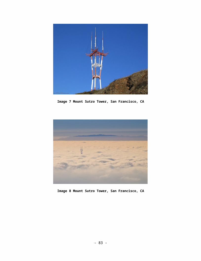
Catalog of Potential Expenses and Estimated Costs
IV. FIGURES
Figure 1: Rigid coaxial line section lengths and the channels not supported.
Transmission line connects the transmitter or combiner output to the antenna, running from the equipment building up the tower to the antenna. While lines typically come in lengths of about 20 feet, the exact section length is determined by the station’s assigned channel. After repacking, the transmission line may have to be replaced depending on whether the new channel is allowable for the existing line section length. This is principally an issue for lines that have been in use to feed a single-station antenna. Transmission line is usually “broadbanded” for use with shared antennas by making minor, non-repeating changes to the section lengths, designed for the channels involved. Following is a chart of transmission line section lengths and the channels that are prohibited for each length.
- 84 -
Widelity, Inc.
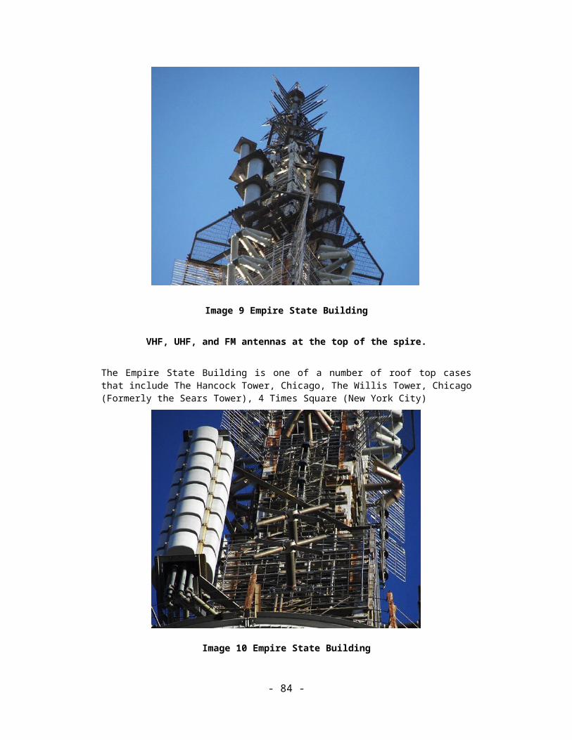
Catalog of Potential Expenses and Estimated Costs
Figure 2: Tower Modifications
This chart provides representative samples of minor, major, and serious tower modifications.
Tower Modifications
Minor Major Serious
Guy wire retensioning Guy wire replacement 2 to 3 levels Guy wire replacement > 4 levels
Tension Diagonal replacement < 12 bays Tension Diagonal replacement > 15 bays Addition of guy levels
Horizontal (struts) reinforcing < 12 levels Horizontal (struts) reinforcing > 15 bays New Anchors for new guy levels
Leg reinforcing (addition of redundants)< 12 levels Horizontal (struts) replacement > 15 bays Replacement of tower sections
Minor foundation reinforcing at anchors Leg reinforcing (addition of redundants) > 15 bays Tension Diagonal replacement > 15 bays
Leg reinforcing (requiring welding) Horizontal (struts) reinforcing > 15 bays
Tension/Compression Diagonal replacement Horizontal (struts) replacement > 15 bays
Tension/Compression Diagonal -requiring welding Leg reinforcing (addition of redundants) > 15 bays
Minor foundation reinforcing at base and anchors Leg reinforcing (requiring welding)
Tension/Compression Diagonal replacement
Tension/Compression Diagonal -requiring welding
Foundation reinforcing at base and anchors
- 85 -
Widelity, Inc.