precast forming and accessories - surebuilt-usa.com
TRANSCRIPT
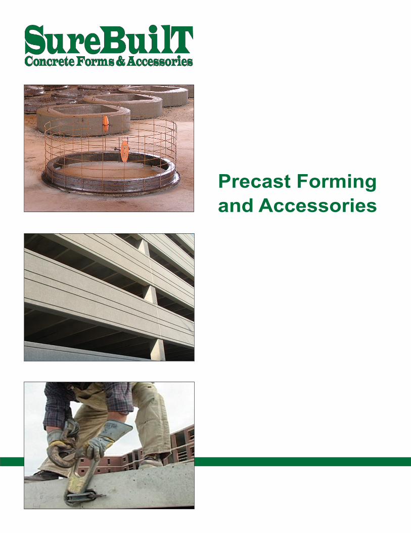
Precast Formingand Accessories

Product specifications are subject to change without notice.
www.surebuilt-usa.com 1
Table of Contents
Coil Inserts .................................................................................................................................................... 3
Ferrule Inserts ........................................................................................................................................... 17
Ring-Lift System ........................................................................................................................................ 25
Uni-Lift System .......................................................................................................................................... 61
Easy-Lift System ....................................................................................................................................... 71
Accessories ............................................................................................................................................... 79
Anchor Rail ............................................................................................................................................. 80
C-Connector ........................................................................................................................................... 89
Chord Connector .................................................................................................................................... 82
Column Base Connector ........................................................................................................................ 83
Edge Connector ...................................................................................................................................... 86
FRP Truss .............................................................................................................................................. 88
M-Connector ........................................................................................................................................... 89
Plastics ................................................................................................................................................... 90
Slant Anchor ........................................................................................................................................... 85
Wall Base Connector .............................................................................................................................. 84
Wire Truss .............................................................................................................................................. 87
Safety Information ....................................................................................................................................... 93
Product Index ............................................................................................................................................. 103

2 Call 708-493-9569
Product specifications are subject to change without notice.

Product specifications are subject to change without notice.
www.surebuilt-usa.com 3
Coil Insert - Criss Cross 8
Coil Insert - Double Flare 8
Coil Insert - Flare 7
Coil Insert - L-Leg 9
Coil Insert - Loop 6
Coil Insert - Open Coil 9
Coil Insert - Thin Slab 10
Coil Nut 14
Coil Rod Coupler 13
Coil Tie 2-Strut 4
Coil Tie 4-Strut 5
Double Swivel Lift Plate 15
Edge Lift Plate 16
Flat Washer 14
Lift Angle Bracket 16
Locator Plug 12
Pick-Up Insert 11
Setting Plug 12
Swivel Lift Plate 15
Threaded Plug 12
Coil Rod 13
Coil Inserts

4 Call 708-493-9569
Product specifications are subject to change without notice.
Coil Tie 2-Strut Used in situations when the ends of the tie be
placed away from the face of the wall. Coils are welded to medium carbon steel wire struts
for a consistently safe weld. Safe Working Load (SWL) based on 1/2” setback
from face of concrete. Other sizes and finishes available on request.
A
B B D
C
Coil Tie 2-Strut*
P/N Length (A)
Coil Length (B)
Insert Width (C)
Wire Dia. (D) Bolt Dia Min Edge
Distance** Tension***
SBSCT346 6” 1-3/4” 1-5/8” .375 3/4” 8” 4,500 lbs
SBSCT347 7” 1-3/4” 1-5/8” .375 3/4” 8” 4,500 lbs
SBSCT348 8” 1-3/4” 1-5/8” .375 3/4” 8” 4,500 lbs
SBSCT349 9” 1-3/4” 1-5/8” .375 3/4” 8” 4,500 lbs
SBSCT3410 10” 1-3/4” 1-5/8” .375 3/4” 8” 4,500 lbs
SBSCT016 6” 2-1/16” 2-1/16” .440 1” 8” 6,000 lbs
SBSCT017 7” 2-1/16” 2-1/16” .440 1” 8” 6,000 lbs
SBSCT018 8” 2-1/16” 2-1/16” .440 1” 8” 6,000 lbs
SBSCT019 9” 2-1/16” 2-1/16” .440 1” 8” 6,000 lbs
SBSCT0110 10” 2-1/16” 2-1/16” .440 1” 8” 6,000 lbs
SBSCT1146 6” 2-1/16” 2-1/2” .440 1-1/4” 10” 7,500 lbs
SBSCT1147 7” 2-1/16” 2-1/2” .440 1-1/4” 10” 7,500 lbs
SBSCT1148 8” 2-1/16” 2-1/2” .440 1-1/4” 10” 7,500 lbs
SBSCT1149 9” 2-1/16” 2-1/2” .440 1-1/4” 10” 7,500 lbs
SBSCT1140 10” 2-1/16” 2-1/2” .440 1-1/4” 10” 7,500 lbs
* 2-Strut inserts are not recommended for edge lifts. ** Use additional tension bar if edge distance is less than the minimum specified. *** Safe Working Load (SWL) based on a 4:1 safety factor in 3,000 psi concrete.

Product specifications are subject to change without notice.
www.surebuilt-usa.com 5
A
B
D
B
C
Coil Tie 4-Strut Used with heavy crane-handled forms or precast
concrete segments. Coils are welded to medium carbon steel wire struts
for a consistently safe weld. Safe Working Load (SWL) based on 1/2” setback
from face of concrete. Other sizes and finishes available on request.
HD Coil Tie 4-Strut
P/N Length (A)
Coil Length (B)
Insert Width (C)
Wire Dia. (D) Bolt Dia Min Edge
Distance** Tension* Shear*
SBHCT3464S 6” 2-1/16” 1-5/8” .375 3/4” 8” 6,000 lbs 6,000 lbs
SBHCT3474S 7” 2-1/16” 1-5/8” .375 3/4” 8” 6,000 lbs 6,000 lbs
SBHCT3484S 8” 2-1/16” 1-5/8” .375 3/4” 8” 6,000 lbs 6,000 lbs
SBHCT3494S 9” 2-1/16” 1-5/8” .375 3/4” 8” 6,000 lbs 6,000 lbs
SBHCT34104S 10” 2-1/16” 1-5/8” .375 3/4” 8” 6,000 lbs 6,000 lbs
SBHCT0164S 6” 2-1/16” 2-1/16” .375 1” 10” 9,000 lbs 9,000 lbs
SBHCT0174S 7” 2-1/16” 2-1/16” .375 1” 10” 9,000 lbs 9,000 lbs
SBHCT0184S 8” 2-1/16” 2-1/16” .375 1” 10” 9,000 lbs 9,000 lbs
SBHCT0194S 9” 2-1/16” 2-1/16” .375 1” 10” 9,000 lbs 9,000 lbs
SBHCT01104S 10” 2-1/16” 2-1/16” .375 1” 10” 9,000 lbs 9,000 lbs
SBHCT11464S 6” 3” 2-1/2” .440 1-1/4” 15” 13,500 lbs 12,000 lbs
SBHCT11474S 7” 3” 2-1/2” .440 1-1/4” 15” 13,500 lbs 12,000 lbs
SBHCT11484S 8” 3” 2-1/2” .440 1-1/4” 15” 13,500 lbs 12,000 lbs
SBHCT11494S 9” 3” 2-1/2” .440 1-1/4” 15” 13,500 lbs 12,000 lbs
SBHCT114104S 10” 3” 2-1/2” .440 1-1/4” 15” 13,500 lbs 12,000 lbs
* Safe Working Load (SWL) based on a 4:1 safety factor in 3,000 psi concrete. ** Use additional tension bar if edge distance is less than the minimum specified.
HD Coil Tie 6-Strut
P/N Insert Length (A)
Coil Length (B)
Insert Width (C)
Wire Dia. (D) Bolt Dia Min Edge
Distance* Tension** Shear**
SBHCT11486S 8” 3” 2-1/2” .440 1-1/4” 16” 20,000 lbs 20,000 lbs
SBHCT11496S 9” 3” 2-1/2” .440 1-1/4” 16” 20,000 lbs 20,000 lbs
SBHCT114106S 10” 3” 2-1/2” .440 1-1/4” 16” 20,000 lbs 20,000 lbs
SBHCT114116S 11” 3” 2-1/2” .440 1-1/4” 16” 20,000 lbs 20,000 lbs
SBHCT114126S 12” 3” 2-1/2” .440 1-1/4” 16” 20,000 lbs 20,000 lbs
* Use additional tension bar if edge distance is less than the minimum specified. ** Safe Working Load (SWL) based on a 4:1 safety factor in 3,000 psi concrete.

6 Call 708-493-9569
Product specifications are subject to change without notice.
A
B
D
C
Coil Insert - Loop Helix coils are electrically welded to the struts resulting in a
consistently safe weld Struts fabricated from medium carbon steel (available in
stainless steel SS304 and SS216) SWL based on 1/2” setback from face of concrete
Coil Insert - Loop*
P/N Insert Length (A)
Coil Length (B)
Insert Width (C)
Wire Dia. (D) Bolt Dia Min Edge
Distance Tension**
SBCIL124 4” 1-3/16” 1-5/16” .225 1/2” 8” 2,250 lbs
SBCIL126 6” 1-3/16” 1-3/8” .306 1/2” 8” 3,600 lbs
SBCIL344 4” 1-5/8” 1-5/8” .306 3/4” 8” 3,750 lbs
SBCIL346 6” 1-5/8” 1-7/8” .375 3/4” 8” 4,500 lbs
SBCIL14 4” 2” 2-1/16” .375 1” 8” 3,750 lbs
SBCIL16 6” 2” 2-1/16” .375 1” 8” 4,500 lbs
SBCIL18 8” 2” 2-1/16” .375 1” 8” 4,500 lbs
* 1/2” Coil Insert - Loop are not recommended for edge lifts. ** Safe Working Load (SWL) based on a 4:1 safety factor in 3,000 psi concrete.

Product specifications are subject to change without notice.
www.surebuilt-usa.com 7
A
B
D
E C
Coil Insert - Flare Develops load in low strength concrete better than
straight loops Develops load over a greater area of concrete than other
inserts. Struts fabricated from medium carbon steel wire
(available in stainless steel SS304 and SS216) Helix coils are electrically welded to the struts resulting in
a consistently safe weld SWL based on 1/2” setback from face of concrete
Coil Insert - Flare*
P/N Insert Length (A)
Coil Length (B)
Insert Width (C)
Wire Dia. (D)
Loop Width (E) Bolt Dia Tension**
SBCIF346 6” 1-3/4” 1-3/4” .375 3-1/2” 3/4” 4,750 lbs
SBCIF349 9” 1-3/4” 1-3/4” .375 5-1/2” 3/4” 4,750 lbs
SBCIF19 9” 2-1/16” 2” .375 5-1/2” 1” 4,750 lbs
SBHCIF19 9” 2-1/16” 2-1/2” .440 5-3/4” 1” 8,000 lbs
SBCIF112 12” 2-1/16” 2” .375 5-1/2” 1” 4,750 lbs
SBHCIF112 12” 2-1/16” 2-1/2” .440 5-3/4” 1” 8,000 lbs
SBCIF114 12” 2-5/16” 2-1/2” .375 5-3/4” 1-1/4” 4,750 lbs
SBHCIF114 12” 2-5/16” 2-1/2” .440 5-3/4” 1-1/4” 8,000 lbs
SBCIFL1212 12” 2-5/16” 2-3/4” .440 5-3/4” 1-1/2” 8,000 lbs
* Coil Insert - Flare is not recommended for edge lifts. ** Safe Working Load (SWL) based on a 4:1 safety factor in 3,000 psi concrete.
8 Call 708-493-9569
Product specifications are subject to change without notice.
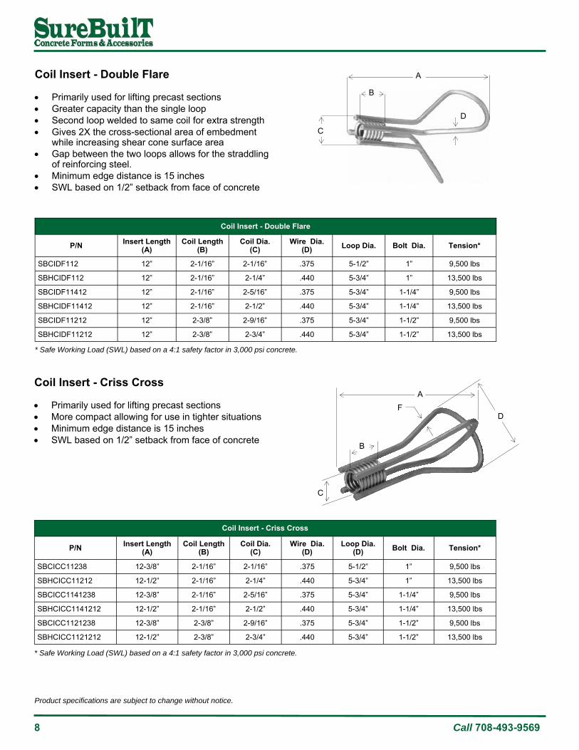
Coil Insert - Double Flare Primarily used for lifting precast sections Greater capacity than the single loop Second loop welded to same coil for extra strength Gives 2X the cross-sectional area of embedment
while increasing shear cone surface area Gap between the two loops allows for the straddling
of reinforcing steel. Minimum edge distance is 15 inches SWL based on 1/2” setback from face of concrete
Coil Insert - Criss Cross Primarily used for lifting precast sections More compact allowing for use in tighter situations Minimum edge distance is 15 inches SWL based on 1/2” setback from face of concrete
A
D
B
C
A
F
C
B
D
Coil Insert - Double Flare
P/N Insert Length (A)
Coil Length (B)
Coil Dia. (C)
Wire Dia. (D) Loop Dia. Bolt Dia. Tension*
SBCIDF112 12” 2-1/16” 2-1/16” .375 5-1/2” 1” 9,500 lbs
SBHCIDF112 12” 2-1/16” 2-1/4” .440 5-3/4” 1” 13,500 lbs
SBCIDF11412 12” 2-1/16” 2-5/16” .375 5-3/4” 1-1/4” 9,500 lbs
SBHCIDF11412 12” 2-1/16” 2-1/2” .440 5-3/4” 1-1/4” 13,500 lbs
SBCIDF11212 12” 2-3/8” 2-9/16” .375 5-3/4” 1-1/2” 9,500 lbs
SBHCIDF11212 12” 2-3/8” 2-3/4” .440 5-3/4” 1-1/2” 13,500 lbs
* Safe Working Load (SWL) based on a 4:1 safety factor in 3,000 psi concrete.
Coil Insert - Criss Cross
P/N Insert Length (A)
Coil Length (B)
Coil Dia. (C)
Wire Dia. (D)
Loop Dia. (D) Bolt Dia. Tension*
SBCICC11238 12-3/8” 2-1/16” 2-1/16” .375 5-1/2” 1” 9,500 lbs
SBHCICC11212 12-1/2” 2-1/16” 2-1/4” .440 5-3/4” 1” 13,500 lbs
SBCICC1141238 12-3/8” 2-1/16” 2-5/16” .375 5-3/4” 1-1/4” 9,500 lbs
SBHCICC1141212 12-1/2” 2-1/16” 2-1/2” .440 5-3/4” 1-1/4” 13,500 lbs
SBCICC1121238 12-3/8” 2-3/8” 2-9/16” .375 5-3/4” 1-1/2” 9,500 lbs
SBHCICC1121212 12-1/2” 2-3/8” 2-3/4” .440 5-3/4” 1-1/2” 13,500 lbs
* Safe Working Load (SWL) based on a 4:1 safety factor in 3,000 psi concrete.

Product specifications are subject to change without notice.
www.surebuilt-usa.com 9
Coil Insert - L-Leg
Composed of a four strut insert Available in bolt diameters of 3/4 to 1-1/2 inches Struts fabricated from medium carbon steel wire Helix coils are electrically welded to the struts
resulting in a consistently safe weld SWL based on 1/2” setback from face of concrete A
E
D
C
B
Coil Insert - Open Coil Designed to give additional load strength in concrete
without increasing the depth of the anchor Available in plain steel or electro-galvanized Available with 2, 4 or 6 struts Accompanying washers are available SWL based on 1/2” setback from face of concrete
Coil Insert - Open Coil
P/N Insert Height (A)
Coil Dia. (B)
Coil Length (C) Wire Dia Struts* Bolt Dia. Min Edge
Distance** Tension*** Shear***
SBCIOC34412 4-1/2” 2-1/8” 1-1/2” .375 2 3/4” 6” 4,250 lbs 4,250 lbs
SBCIOC1512 5-1/2” 2-1/2” 2-1/4” .440 2 1” 7” 6,250 lbs 6,250 lbs
SBCIOC1712 7-1/2” 2-3/4” 2-3/4” .440 4 1” 10” 10,000l bs 12,000 lbs
SBCIOC114712 7-1/2” 3” 2-3/4” .440 4 1-1/4” 10” 12,000 lbs 12,000 lbs
SBCIOC114912 9-1/2” 3” 3-5/8” .440 6 1-1/4” 12” 16,000 lbs 16,000 lbs
SBCIOC1112912 9-1/2” 3-3/8” 3-5/8” .440 6 1-1/2” 12” 16,000 lbs 16,000 lbs
* 2-Strut inserts are not recommended for edge lifts. ** Use additional tension bar if edge distance is less than the minimum specified. *** Safe Working Load (SWL) based on a 4:1 safety factor in 3,000 psi concrete.
A
B
C
Coil Insert - L-Leg
P/N Insert Height (A)
Coil Length (B)
Coil Dia. (C)
Leg Length (D)
Wire Dia. (E) Bolt Dia. Min Edge
Distance Tension*
SBCILL343 3” 1-3/4” 1-5/8” 7-1/8” .306 3/4” 9” 2,500 lbs
SBCILL14 4” 2-1/16” 1-7/8” 9-1/2” .306 1” 12” 3,500 lbs
SBCILL1144 4” 2-1/16” 2-1/4” 9-3/4” .375 1-1/4” 12” 4,000 lbs
SBCILL1124 4” 2-1/16” 2-1/2” 10” .375 1-1/2” 12” 4,000 lbs
* Safe Working Load (SWL) based on a 4:1 safety factor in 3,000 psi concrete.

10 Call 708-493-9569
Product specifications are subject to change without notice.
Coil Insert - Thin Slab Designed for use in small sections or thin slabs
where larger inserts will not fit Used for small loads only Fixing plate available SWL based on 1/2” setback from face of concrete
B D
A C
E
Coil Insert - Thin Slab*
P/N Insert Height (A)
Insert Width (B)
Coil Length (C)
Coil Dia (D)
Wire Dia (E) Bolt Dia Min Edge
Distance Tension**
SBCITS12214 2-1/4” 4-1/8” 1-1/8” 1-1/4” .225 1/2” 4” 950 lbs
SBCITS34214 2-1/4” 5” 1-5/8” 1-5/8” .306 3/4 5” 2,000 lbs
SBCITS34312 3-1/2” 6” 2” 2” .306 3/4” 6” 3,400 lbs
SBCITS1212 2-1/2” 6” 2” 2” .306 1” 5” 2,000 lbs
SBCITS1412 4-1/2” 6” 2” 2” .306 1” 8” 4,750 lbs
* Recommended for thin slabs only. Limited load capacity. ** Safe Working Load (SWL) based on a 4:1 safety factor in 3,000 psi concrete.
Product specifications are subject to change without notice.
www.surebuilt-usa.com 11
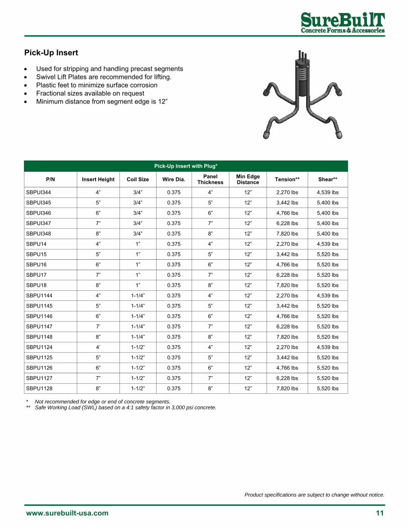
Pick-Up Insert Used for stripping and handling precast segments Swivel Lift Plates are recommended for lifting. Plastic feet to minimize surface corrosion Fractional sizes available on request Minimum distance from segment edge is 12”
Pick-Up Insert with Plug*
P/N Coil Size Wire Dia. Panel Thickness
SBPUI344 3/4” 0.375 4”
SBPUI345 3/4” 0.375 5”
SBPUI346 3/4” 0.375 6”
SBPUI347 3/4” 0.375 7”
Tension**
2,270 lbs
3,442 lbs
4,766 lbs
6,228 lbs
Shear**
4,539 lbs
5,400 lbs
5,400 lbs
5,400 lbs
SBPUI348 3/4” 0.375 8” 7,820 lbs 5,400 lbs
SBPU14 1” 0.375 4” 2,270 lbs 4,539 lbs
SBPU15 1” 0.375 5” 3,442 lbs 5,520 lbs
SBPU16 1” 0.375 6” 4,766 lbs 5,520 lbs
SBPU17 1” 0.375 7” 6,228 lbs 5,520 lbs
SBPU18 1” 0.375 8” 7,820 lbs 5,520 lbs
SBPU1144 1-1/4” 0.375 4” 2,270 lbs 4,539 lbs
SBPU1145 1-1/4” 0.375 5” 3,442 lbs 5,520 lbs
SBPU1146 1-1/4” 0.375 6” 4,766 lbs 5,520 lbs
SBPU1147 1-1/4” 0.375 7” 6,228 lbs 5,520 lbs
SBPU1148 1-1/4” 0.375 8” 7,820 lbs 5,520 lbs
SBPU1124 1-1/2” 0.375 4” 2,270 lbs 4,539 lbs
SBPU1125 1-1/2” 0.375 5” 3,442 lbs 5,520 lbs
SBPU1126 1-1/2” 0.375 6” 4,766 lbs 5,520 lbs
SBPU1127 1-1/2” 0.375 7” 6,228 lbs 5,520 lbs
SBPU1128 1-1/2” 0.375 8” 7,820 lbs 5,520 lbs
Insert Height
4”
5”
6”
7”
8”
4”
5”
6”
7”
8”
4”
5”
6”
7’
8”
4’
5”
6”
7”
8”
Min Edge Distance
12”
12”
12”
12”
12”
12”
12”
12”
12”
12”
12”
12”
12”
12”
12”
12”
12”
12”
12”
12”
* Not recommended for edge or end of concrete segments. ** Safe Working Load (SWL) based on a 4:1 safety factor in 3,000 psi concrete.

12 Call 708-493-9569
Product specifications are subject to change without notice.
Locator Plug
P/N Description Length Below Coil
SBLP34 Locator Plug 3/4” Coil 1-1/2”
SBLP1 Locator Plug 1” Coil 1-5/8”
SBP114 Locator Plug 1-1/4” Coil 1-3/4”
Locator Plug Two-piece plastic design snaps together within coil Plug creates void for subsequent bolt engagement Antenna identifies plug location at concrete surface
Threaded Plug
P/N Description
SBTPPC38 Threaded Plug 3/8" (10)
SBTPPC12 Threaded Plug 1/2" (13)
SBTPPC58 Threaded Plug 5/8" (16)
SBTPPC34 Threaded Plug 3/4" (19)
Setting Plug—Plastic
P/N Description
SBPSP12 Setting Plug 1/2”x2-1/2” Plastic
SBPSP34 Setting Plug 3/4”x3-3/4” Plastic
SBPSP1 Setting Plug 1”x5” Plastic
Threaded Plug
Threaded plugs can be used with coil inserts and anchors to keep the threads clean during concrete placement.
Setting Plug Setting plugs are used to position and fasten inserts to forms. The nail hole through the center of the plug provides access and quick attachment.
Setting Plug—Steel with Magnet
P/N Description
SBGB100126CR Setting Plug 1/2”x6” wMagnet
SBGB100346CR Setting Plug 3/4”x6” wMagnet
SBGB10016CR Setting Plug 1”x6” wMagnet
SBGB1001146CR Setting Plug 1-1/4”x6” wMagnet

Product specifications are subject to change without notice.
www.surebuilt-usa.com 13
Coil Rod
The most common uses for Coil Rod in precast concrete operations include: Anchors Coil Tie combination for variable wall thickness External tie method for corner or column forms
Coil Rod Coupler
The coupler is used to maintain the load rating when joining two lengths of coil rod. The coupler is tapped from each end, providing a stop at the center to indicate full thread engagement.
Coil Rod Coupler
P/N Description Load Rating*
SBCRC12 Coil Rod Coupler 1/2” 9,000 lbs
SBCRC114 Coil Rod Coupler 1-1/4” 56,000 lbs
SBCRC112 Coil Rod Coupler 1-1/2” 68,000 lbs
SBCRC1 Coil Rod Coupler 1” 38,000 lbs
SBCRC78 Coil Rod Coupler 7/8” 24,000 lbs
SBCRC58 Coil Rod Coupler 5/8” 12,000 lbs
SBCRC34 Coil Rod Coupler 3/4” 18,000 lbs
Length
2-3/4”
3-1/4”
3-1/4”
4-1/4”
4-1/2”
5-3/4”
7”
Dia
1/2”
5/8”
3/4”
7/8”
1”
1-1/4”
1-1/2”
* Load rating based on 2:1 safety factor.
Coil Rod
P/N Description Load Rating*
SBCR12 Coil Rod 1/2” x 12’ 9,000 lbs
SBCR114 Coil Rod 1-1/4” x 12’ 56,000 lbs
SBCR112 Coil Rod 1-1/2” x 12’ 68,000 lbs
SBCR1 Coil Rod 1” x 12’ 38,000 lbs
SBCR78 Coil Rod 7/8” x 12’ 24,000 lbs
SBCR58 Coil Rod 5/8” x 12’ 12,000 lbs
SBCR34 Coil Rod 3/4” x 12’ 18,000 lbs
* Load rating based on 2:1 safety factor.

14 Call 708-493-9569
Product specifications are subject to change without notice.
Flat Washer Flat washers are used with all sizes of coil rod. The washers are designed to provide adequate bearing at walers or form joints.
Coil Nut
Flat Washer*
P/N Description Rating*
SBFW1434916 Flat Washer 1/4”x4”x3” with 9/16” hole 1,800 lbs
SBFW14451316 Flat Washer 1/4”x4”x5” with 13/16” hole 2,700 lbs
SBFW12551116 Flat Washer 1/2”x5”x5” with 1-1/16” hole 7,200 lbs
SBFW12551516 Flat Washer 1/2”x5”x5” with 1-5/16” hole 10,800 lbs
SBFW34551916 Flat Washer 3/4”x5”x5” with 1-9/16” hole 15,000 lbs
Bolt Size
1/2”
3/4”
1”
1-1/4”
1-1/2”
* Load rating based on double waler channel at 2:1 safety factor.
Coil Bolt
P/N Description w/Single Nut* w/Double Nut*
SBCN12 Coil Nut 1/2” 6,000 lbs 9,000 lbs
SBCN58 Coil Nut 5/8” 8,000 lbs 12,000 lbs
SBCN34 Coil Nut 3/4” 9,000 lbs 18,000 lbs
SBCN78 Coil Nut 7/8” 15,000 lbs 24,000 lbs
SBCN1 Coil Nut 1” 24,000 lbs 38,000 lbs
SBCN114 Coil Nut 1-1/4” 36,000 lbs 56,000 lbs
SBCN112 Coil Nut 1-1/2” 47,500 lbs 68,000 lbs
SBCN12HH Coil Nut 1/2” Heavy Hex 9,000 lbs --
SBCN58HH Coil Nut 5/8” Heavy Hex 12,000 lbs --
SBCN34HH Coil Nut 3/4” Heavy Hex 18,000 lbs --
SBCN78HH Coil Nut 7/8” Heavy Hex 24,000 lbs --
SBCN1HH Coil Nut 1” Heavy Hex 38,000 lbs --
SBCN114HH Coil Nut 1-1/4” Heavy Hex 56,000 lbs --
SBCN112HH Coil Nut 1-1/2” Heavy Hex 68,000 lbs --
Height
1/2”
5/8”
3/4”
7/8”
1”
1-1/4”
1-1/2”
1”
1-1/4”
1-1/2”
1-3/4”
2”
2-1/2”
3”
Width at Flats
7/8”
1”
1-1/8”
1-3/8”
1-5/8”
2”
2-3/8”
7/8”
1”
1-1/8”
1-3/8”
1-5/8”
2”
2-3/8”
* Load rating based on 2:1 safety factor.
Coil Nut
Coil Nut - Heavy Hex
Flat Washer

Product specifications are subject to change without notice.
www.surebuilt-usa.com 15
Swivel Lift Plate Designed for attaching to any type of single lift insert Available in 3/4” and 1” coil bolt sizes
Double Swivel Lift Plate Permits rotation of the bail in the direction of the rigging and
applied loading Bail portion of the lift plate rotates a full 360° in horizontal
plane and will also swivel 180° in a vertical plane
W
H
A
B
C
D
Swivel Lift Plate
P/N A B C D Bolt Dia. Min Bolt Length Tension*
SBSLP34 5” 2-5/8” 5-1/8” 5/8” 3/4”: 4” 7,000 lbs
SBSLP1 5” 2-5/8” 5-1/8” 5/8” 1” 5” 10,000 lbs
* Load rating based 5:1 safety factor.
Double Swivel Lift Plate
P/N H W Bolt Dia Min Bolt Length* Tension**
SBDSLP34 1-1/2” 5” 3/4 4-1/2” 7,000 lbs
SBDSLP1 2” 5” 1 5” 10,000 lbs
SBDSLP114 2-3/4” 7” 1-1/4 6” 15,000 lbs
SBDSLP112 2-3/4” 7” 1-1/2 6” 20,000 lbs
* Minimum 150ksi bolt required. ** Load rating based 5:1 safety factor.

16 Call 708-493-9569
Product specifications are subject to change without notice.
Lift Angle Bracket The Lift Angle Bracket is generally used for face lifting tilt-up panels, but it can also be used for edge lift conditions when the panel thickness is 6” or greater. Cut washers are required under the head of each bolt.
Edge Lift Plate The Edge Lifting Plate is designed to be used with either the double edge or double end pick-up insert. Minimum coil bolt length to be used is 4”. Cut washers are required for each bolt.
A
B
T
L
W
W
T
W
L
H
S
Lifting Angle
P/N A B L T W Bolt Dia. Min Bolt Length Tension*
SBLAB1 12” - 21” 3/4” 6” 1” 4” 12,000 lbs
SBLAB114 - 15” 21” 3/4” 6” 1-1/4” 4” 18,000 lbs
SBLAB112 - 15” 21” 3/4” 6” 1-1/2” 4” 18,000 lbs
* Load rating based 5:1 safety factor.
Edge Lifting Plate
P/N H L S T W Bolt Dia. Min Bolt Length Tension*
SBELP34 5-1/2” 18” 12” 1” 4” 3/4” 4” 8,800 lbs
SBELP1 5-1/2” 18” 12” 1” 4” 1” 4” 8,800 lbs
* Load rating based 5:1 safety factor.

Product specifications are subject to change without notice.
www.surebuilt-usa.com 17
Ferrule Inserts
Ductile Ferrule Insert 22
Ferrule 18
Ferrule Insert - Flare 19
Ferrule Insert - L-Leg 20
Ferrule Insert - Loop 18
Ferrule Insert - Open Coil 21
Ferrule Insert - Thin Slab 20
Ferrule Insert - Wing 19
Plastic Insert 24
Plastic Plug 23
Precast Insert 24
Threaded Plug 23

18 Call 708-493-9569
Product specifications are subject to change without notice.
L
D
L
D
F
W
Ferrule The ferrule is made from solid bar stock and available in all bolt diameters. The bottom end of the ferrule is closed to prevent concrete from entering. The minimum bolt engagement for a ferrule is the bolt diameter plus 1/8” inch. Ferrules accept NC threaded bolts or rod. Bolt lengths are important because ferrules are closed at the bottom end. A ferrule may be substituted in a coil product (see previous section). Ferrules and coils (of same diameter) will have the same load capacities.
Ferrule Insert - Loop Ferrule Inserts are designed to permanently attach a precast panel to a building frame or as a mechanical connection for electrical trays, pipe hangers, sprinkler systems or other suspended items. Ferrules accept NC threaded bolts or rod. Bolt lengths are important because ferrules are closed at the bottom end.
Ferrule Only
P/N Description Diameter (D)
Length (L) Threads Maximum
Engagement
SBFO38PL Ferrule Only 3/8” 9/16” 1-1/4” 16/inch 3/4”
SBFO12PL Ferrule Only 1/2” 11/16” 1-3/8” 13/inch 1”
SBFO58PL Ferrule Only 5/8” 7/8” 1-5/8” 11/inch 1-1/8”
SBFO34PL Ferrule Only 3/4” 1” 1-5/8” 10/inch 1-1/8”
SBFO78PL Ferrule Only 7/8” 1-3/8” 1-5/8” 9/inch 1-1/8”
SBFO1PL Ferrule Only 1” 1-3/8” 1-5/8” 8/inch 1-1/8”
Ferrule Insert - Straight Loop
P/N Diameter (D)
Ferrule (F)
Length (L)
Wire (W)
Bolt Dia
Min Edge Distance Tension*
SBFIL124 11/16” 1-3/8” 4-1/8” .225 1/2” 5” 3,000 lbs
SBFIL126 11/16” 1-3/8” 6-1/8” .306 1/2” 8” 4,000 lbs
SBFIL584 7/8” 1-5/8” 4-1/8” .225 5/8” 5” 3,000 lbs
SBFIL586 7/8” 1-5/8” 6-1/8” .375 5/8” 8” 5,000 lbs
SBFIL344 1” 1-5/8” 4-1/8” .225 3/4” 5” 3,000 lbs
SBFIL346 1” 1-5/8” 6-1/8” .375 3/4” 9” 5,000 lbs
SBFIL786 1-3/8” 1-5/8” 6-1/8” .375 7/8” 9” 5,000 lbs
SBFIL16 1-3/8” 1-5/8” 6-1/8” .375 1” 9” 5,000 lbs
SBFIL18 1-3/8” 1-5/8” 8-1/8” .375 1” 9” 6,000 lbs
* Safe Working Load (SWL) based on 3:1 safety factor in 3,000 psi concrete with 1/2” set-back from surface.

Product specifications are subject to change without notice.
www.surebuilt-usa.com 19
Ferrule Insert - Flare*
P/N Diameter (D)
Ferrule (F)
Length (L)
Radius (R)
Wire (W)
Bolt Dia
Min Edge Distance Tension**
SBFIF38234 9/16” 1-1/4” 2-3/4” 9/16” .243 3/8” 5” 2,000 lbs
SBFIF12234 11/16” 1-3/8” 2-3/4” 9/16” .243 1/2” 5” 2,000 lbs
SBFIF58312 7/8” 1-5/8” 3-1/2” 13/16” .262 5/8” 5” 2,300 lbs
SBFIF34312 1” 1-5/8” 3-1/2” 13/16” .262 3/4” 5” 2,400 lbs
SBFIF786 1-1/4” 1-5/8’ 6” 1-3/8” .375 7/8” 8” 5,300 lbs
SBFIF16 1-3/8” 1-5/8” 6” 1-3/8” .375 1” 8” 5,300 lbs
Ferrule Insert - Wing*
P/N Diameter (D)
Ferrule (F)
Height (H)
Length (L)
Wire (W)
Bolt Dia
Min Edge Distance Tension**
SBFIW12134 11/16” 1-3/8 1-3/4” 4-1/2” .225 1/2” 5” 1,200 lbs
SBFIW582716 7/8” 1-5/8 2-7/16” 4-3/4” .306 5/8” 6” 2,500 lbs
SBFIWI342716 1” 1-5/8 2-7/16” 4-7/8” .306 3/4” 6” 2,650 lbs
SBFIW34358 1-3/8” 1-5/8 3-5/8” 4-7/8” .306 3/4” 8” 4,500 lbs
SBFIW12716 1-3/8” 1-5/8 2-7/16” 5-1/8” .375 1” 6” 4,500 lbs
SBFIW1458 1-3/8” 1-5/8 4-5/8” 5-1/8” .375 1” 9” 6,500 lbs
H
L
D
F
W
Ferrule Insert - Flare The Flared Loop is designed to permanently attach a precast panel to a building frame or as a mechanical connection for electrical trays, pipe hangers, sprinkler systems or other suspended items. Ferrules accept NC threaded bolts or rod. Bolt lengths are important because ferrules are closed at the bottom end.
Ferrule Insert - Wing The Wing Loop is designed for a limited concrete clearance when other inserts will not fit. The insert provides more capacity than standard inserts of the same height.
L
F
D
R
W
* Ferrule Insert - Flared Loop is not recommended as a lifting insert. ** Safe Working Load (SWL) based on 3:1 safety factor in 3,000 psi concrete with 1/2” set-back from surface.
* Ferrule Insert - Flared Loop is not recommended as a lifting insert. ** Safe Working Load (SWL) based on 3:1 safety factor in 3,000 psi concrete with 1/2” set-back from surface.

20 Call 708-493-9569
Product specifications are subject to change without notice.
H
D
L
R
W
Ferrule Insert - L-Leg The L-Leg is designed to permanently attach a precast panel to a building frame or as a mechanical connection for electrical trays, pipe hangers, sprinkler systems or other suspended items. Ferrules accept NC threaded bolts or rod. Bolt lengths are important because ferrules are closed at the bottom end.
Ferrule Insert - Thin Slab The Thin Slab 2-Strurt is designed for limited concrete clearance when no other insert type will fit. The 4” strut lengths are welded near the bottom of the ferrule. Note: The capacity of this insert is limited and the working load should never be exceeded.
L W
D
Ferrule Insert - L-Leg*
P/N Diameter (D)
Height (H)
Length (L)
Leg Length (R)
Wire Dia (W)
Bolt Dia
Min Edge Distance Tension**
SBFILL34318 1” 3-1/8” 1-5/8” 7” .306 3/4” 7” 3,500 lbs
SBFILL1418 1-3/8” 4-1/8” 1-5/8” 9-1/2” .306 1” 9” 4,500 lbs
* When used as a lifting insert, the Safe Working Load (SWL) must be calculated on 4:1 safety factor ** Safe Working Load (SWL) based on 3:1 safety factor in 3,000 psi concrete with 1/2” set-back from surface.
Ferrule Insert - Thin Slab
P/N Diameter (D)
Length (L)
Wire Dia (W)
Bolt Dia Tension*
SBFITS38114 9/16” 1-1/4” .261 3/8” 450 lbs
SBFITS12138 11/16” 1-3/8” .261 1/2” 900 lbs
SBFITS58158 7/8” 1-5/8” .261 5/8” 1,000 lbs
SBFITS34158 1” 1-5/8” .261 3/4” 1,600 lbs
SBFITS78158 1-3/8” 1-5/8” .261 7/8” 1,600 lbs
SBFITS1158 1-3/8” 1-5/8” .261 1” 1,600 lbs
* Safe Working Load (SWL) based on 3:1 safety factor in 3,000 psi concrete with 1/2” set-back.

Product specifications are subject to change without notice.
www.surebuilt-usa.com 21
Ferrule Insert - Open Coil Designed to develop higher load capacities without
increasing depth of insert Adequate vibration is necessary to assure concrete
surrounds the open coil B
D
C A
Ferrule Insert - Open Coil
P/N Length (A)
Coil Dia (B)
Coil (C)
Wire Dia (W) Struts Bolt
Dia Min Edge Distance Tension* Shear*
SBFIOC34458 4-5/8” 2-1/8” 1-1/2 .375 2 3/4” NC 6” 4,250 lbs 4,250 lbs
SBFIOC78618 6-1/8” 2-1/2” 2-1/4 .375 2 7/8” NC 7” 5,000 lbs 5,000 lbs
SBFIOC1558 5-5/8” 2-1/2” 2-1/4 .440 2 1” NC 7” 6,250 lbs 6,250 lbs
SBFIOC1758 7-5/8” 2-3/4” 2-3/4 .440 4 1” NC 10” 10,000 lbs 12,000 lbs
SBFIOC114758 7-5/8” 3” 2-3/4 .440 4 1-1/4” NC 10” 12,000 lbs 12,000 lbs
SBFIOC114958 9-5/8” 3” 3-5/8 .440 6 1-1/4” NC 12” 16,000 lbs 16,250 lbs
SBFIOC112958 9--5/8” 3-3/8” 3-5/8 .440 6 1-1/2” NC 12” 16,000 lbs 16,250 lbs
* Safe Working Load (SWL) based on 4:1 safety factor in 3,000 psi concrete with 1/2” set-back from surface.

22 Call 708-493-9569
Product specifications are subject to change without notice.
Ductile Ferrule Insert The Ductile Ferrule Insert provides additional load strength in concrete segments. These inserts can be used for lifting, handling and mounting structural concrete components. The foot creates a large shear area in the concrete. Couplers, bolts and nuts can be supplied in round or hex versions. Use with the Double Swivel Lift Plate for maximum capacity. Also available in coil thread, example SBDC1125.
Foot Dia. (C)
Insert Length (A)
Thread Depth
Ductile Insert*
P/N Length (A)
Foot Dia. (C)
Thread Depth
Bolt Dia
Min Edge Distance Ultimate**
SBDFI125 5” 1 7/8” 1/2” NC 8” 18,000 lbs
SBDFI586 6” 1-1/4 1” 5/8” NC 10” 24,000 lbs
SBDFI347 7” 1-1/2 1-1/4” 3/4” NC 12” 34,600 lbs
SBDFI78712 7-1/2” 1-3/4 1-3/8” 7/8” NC 15” 43,000 lbs
SBDFI18 8” 2 1-1/2” 1” NC 16” 59,000 lbs
SBDFI11810 10” 2-1/4 1-3/4” 1-1/8” 20” 75,500 lbs
SBDFI11412 12” 2-1/2 2” 1-1/4” 24” 96,000 lbs
The bolt or rod connection must be equal to a Grade 8 or A325. Minimum bolt penetration for full load transfer is minimum 1.5 x bolt diameter. Rebar connection meets minimum 125% of specified yield requirements.
Type 1 Threaded Rebar
Ductile Insert
* When used as a lifting insert, the Safe Working Load (SWL) must be calculated using a 4:1 safety factor. When used as a permanent connection, the Safe Working Load (SWL) must be calculated at 3:1 safety factor. When used as a temporary connection, the Safe Working Load (SWL) must be calculated at 2:1 safety factor. ** Ultimate strength based on 3,500 psi concrete.
Product specifications are subject to change without notice.
www.surebuilt-usa.com 23
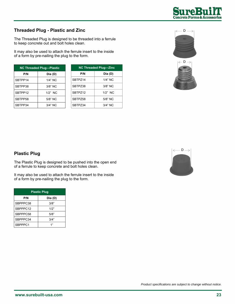
Plastic Plug
P/N Dia (D)
SBPPPC38 3/8”
SBPPPC12 1/2”
SBPPPC58 5/8”
SBPPPC34 3/4”
SBPPPC1 1”
Plastic Plug The Plastic Plug is designed to be pushed into the open end of a ferrule to keep concrete and bolt holes clean. It may also be used to attach the ferrule insert to the inside of a form by pre-nailing the plug to the form.
D
Threaded Plug - Plastic and Zinc The Threaded Plug is designed to be threaded into a ferrule to keep concrete out and bolt holes clean. It may also be used to attach the ferrule insert to the inside of a form by pre-nailing the plug to the form.
D
NC Threaded Plug—Plastic
P/N Dia (D)
SBTPP14 1/4” NC
SBTPP38 3/8” NC
SBTPP12 1/2” NC
SBTPP58 5/8” NC
SBTPP34 3/4” NC
D
NC Threaded Plug—Zinc
P/N Dia (D)
SBTPZ14 1/4” NC
SBTPZ38 3/8” NC
SBTPZ12 1/2” NC
SBTPZ58 5/8” NC
SBTPZ34 3/4” NC

24 Call 708-493-9569
Product specifications are subject to change without notice.
Bolt Dia.
L
Precast Concrete Insert - Plastic Threaded precast concrete insert Corrosion resistant plastic Foot creates large shear cone in thin panels
NC Precast Concrete Insert - Steel
P/N Bolt Dia. Length (L) Threads Safe Working
Load*
SBPCIS14112 1/4” 1-1/2” 20/in 575 lbs
SBPCIS381 3/8” 1” 16/in 1,025 lbs
SBPCIS38138 3/8” 1-3/8” 16/in 1,200 lbs
SBPCIS12112 1/2” 1-1/2” 13/in 1,225 lbs
SBPCIS12278 1/2” 2-7/8” 13/in 2,025 lbs
SBPCIS581116 5/8” 1-11/16” 11/in 1,575 lbs
SBPCIS58278 5/8” 2-7/8” 11/in 2,500 lbs
SBPCIS3411116 3/4” 1-11/16” 10/in 1,725 lbs
SBPCIS34278 3/4” 2-7/8” 10/in 3,125 lbs
* Safe Working Load (SWL) based on 3:1 safety factor in 3000 psi concrete.
L
Bolt Dia.
Precast Concrete Insert - Steel Threaded precast concrete insert Made from corrosion resistant zinc alloy Foot creates large shear cone in thin panels
NC Precast Insert - Plastic
P/N Bolt Dia. Length (L) Tension*
SBPCIP38 3/8” 1-1/2” 600 lbs
SBPCIP12134 1/2” 1-3/4” 1,100 lbs
SBPCIP12234 1/2” 2-3/4” 1,880 lbs
SBPCIP58 5/8” 3” 2,250 lbs
SBPCIP34 3/4” 3” 2,800 lbs
* Safe Working Load (SWL) based on 3:1 safety factor in 3000 psi concrete.

Product specifications are subject to change without notice.
www.surebuilt-usa.com 25
Cable Lifter 56
Chain Lifter 56
Double Tee Anchor 31
Drop-Forged Foot Erection Anchor 44
Erection Anchor 34
Erection Anchor w/Shear Plate 35
Foot Anchor 28
HD Sandwich Panel Erection Anchors 46
Lifter 55
Magnet Plates 59
Mounting Plate for Recess Former 59
Plate Anchor 33
Recess Former - Plastic 57
Recess Former - Urethane 57
Recess Former - Steel 58
Ring-Lift Lifter 55
Sandwich Panel Erection Anchors 48
Shear Bar 42
Straight Leg Erection Anchor w/Shear 43
Straight Leg Insert 30
T-Bar Anchor 27
Tension Bar 42
Two-Hole Anchor 26
Uni-Anchor 29
Wavy Tail Anchor 32
X-Foot Erection Anchors 37
X-Foot Erection Anchors w/Shear Plate 39
Ring-Lift System

26 Call 708-493-9569
Product specifications are subject to change without notice.
Two-Hole Anchor
P/N Tons Clutch ID
Length (L)
Width (W)
Thickness (T) Tension*
SBTHA2T384 2T 2-2.5T 4” 1-1/4” 3/8” 4,000 lbs
SBTHA4T584 4T 4-5T 4” 1-1/2” 5/8” 8,000 lbs
SBTHA8T347 8T 8-10T 7” 2-1/2” 3/4” 16,000 lbs
Two-Hole Anchor The Two-Hole Anchor is used for stripping panels from tilt tables and handling panels. The anchor is also appropriate for high-tension loads that cannot be held with other anchors or panels constructed of lightweight concrete. The full safe working load of the Two-Hole Anchor can be achieved in a thin slab or with low concrete strength by using a Tension Bar (see below). The wider distribution of shear forces allows for the raising thin or low compressive strength panels. Available in black, galvanized (G) and hot-dip galvanized (HDG) finish.
T
L
W
2T
L
30°
Tension Bar Length (L) Requirement*
P/N Load Rebar 2,000 psi 3,000 psi 5,000 psi
SBTB2T 2-2.5T #4 2-9” 2’-6” 1’-8”
SBTB4T 4-5T #5 3’-6” 3’-0” 2’-2”
SBTB8T 6-8-10T #6 5’-6” 4’-6” 3’-3”
Concrete Strength
Tension Bar The Tension Bar is used with the Erection Anchor to distribute tension loads into the precast segment.
* Minimum reinforcing length (L) needed to develop the full strength of the anchor.

Product specifications are subject to change without notice.
www.surebuilt-usa.com 27
* Minimum edge distance is 2x embedded depth. Minimum anchor spacing is 4x embedded depth. ** Safe Working Load based on a safety of 4: 1 in 3,500 psi concrete. Handling panels requires sufficient sling or cable length., Sling angle inclination factors apply.
T-Bar Anchor The T-Bar Anchor can be placed at the face, back or edge of precast panels to allow for back-stripping and rotation from horizontal-to-vertical. Available in black, galvanized (G) and hot-dip galvanized (HDG) finish.
T-Bar Anchor*
P/N Tons Length (L)
Width (W)
Thickness (T)
Bar Dia (B)
Minimum Panel
Tension and Shear**
SBTBA2T434 2T 4" 1-1/4" 3/8" 1/2" 4-3/4" 4,000 lbs
SBTBA2T578 2T 5-1/2" 1-1/4" 3/8" 1/2" 5-7/8" 4,000 lbs
SBTBA4T458 4T 4-1/4" 1-1/2" 5/8" 1/2" 4-5/8" 5,500 lbs
SBTBA4T518 4T 4-3/4" 1-1/2" 5/8" 1/2" 5-1/8" 7,100 lbs
SBTBA4T558 4T 5-1/4" 1-1/2" 5/8" 1/2" 5-5/8" 8,000 lbs
SBTBA4T618 4T 5-3/4" 1-1/2" 5/8" 1/2" 6-1/8" 8,000 lbs
SBTBA4T658 4T 6-1/4" 1-1/2" 5/8" 1/2" 6-5/8" 8,000 lbs
SBTBA4T718 4T 6-3/4" 1-1/2" 5/8" 1/2" 7-1/8" 8,000 lbs
SBTBA4T758 4T 7-1/4" 1-1/2" 5/8" 1/2" 7-5/8" 8,000 lbs
SBTBA4T818 4T 7-3/4" 1-1/2" 5/8" 1/2" 8-1/8" 8,000 lbs
SBTBA8T1112 8T 6-1/8" 2-1/2" 3/4" 3/4" 11-1/2" 8,900 lbs
SBTBA8T1134 8T 11-1/8" 2-1/2" 3/4" 3/4" 11-3/4" 16,000 lbs
L
T W
B

28 Call 708-493-9569
Product specifications are subject to change without notice.
Foot Anchor The drop-forged Foot Anchor handles most face lifting applications by developing a shear cone. The strong forged metal ensures structural integrity for consistently safe lifts. The foot develops a high-tension, high-capacity shear cone in concrete slabs. It is available in many sizes and can handle most face lifting applications. For reduced edge distance, spacing or low strength concrete, add additional rebar around the anchor.
L
W
S
C
Foot Anchor*
P/N Tons Clutch Length (L)
Width (W)
Shaft (S)
Foot Dia (C)
Min Edge Distance**
Tension and Shear***
SBRFA25312G 2.5T 2-2.5T 3-1/2” 1-5/16” 1/2” 1-1/2” 6” 3,900 lbs
SBRFA25512G 2.5T 2-2.5T 5-1/2” 1-5/16” 1/2” 1-1/2” 10-1/2” 4,510 lbs
SBRFA25612G 2.5T 2-2.5T 6-1/2” 1-5/16” 1/2” 1-1/2” 11” 5,000 lbs
SBRFA5312G 5T 4-5T 3-1/2” 1-13/16” 3/4” 2-1/4” 6” 4,400 lbs
SBRFA5512G 5T 4-5T 5-1/2” 1-13/16” 3/4” 2-1/4” 10-1/2” 8,500 lbs
SBRFA5712G 5T 4-5T 7-1/2” 1-13/16” 3/4” 2-1/4” 12-1/2” 9,000 lbs
SBRFA5912G 5T 4-5T 9-1/2” 1-13/16” 3/4” 2-1/4” 16” 11,000 lbs
SBRFA10512G 10T 8-10T 5-1/2” 2-5/8” 1-1/8” 2-7/8” 10” 8,800 lbs
SBRFA107G 10T 8-10T 7” 2-5/8” 1-1/8” 2-7/8” 12” 12,500 lbs
SBRFA1010G 10T 8-10T 10” 2-5/8” 1-1/8” 2-7/8” 17” 22,000 lbs
* Minimum spacing distance of 4x anchor depth. ** Minimum edge distance of 2x embedded anchor depth. *** Safe Working Load (SWL) based on 4:1 safety factor in 3,500 psi concrete.
Product specifications are subject to change without notice.
www.surebuilt-usa.com 29
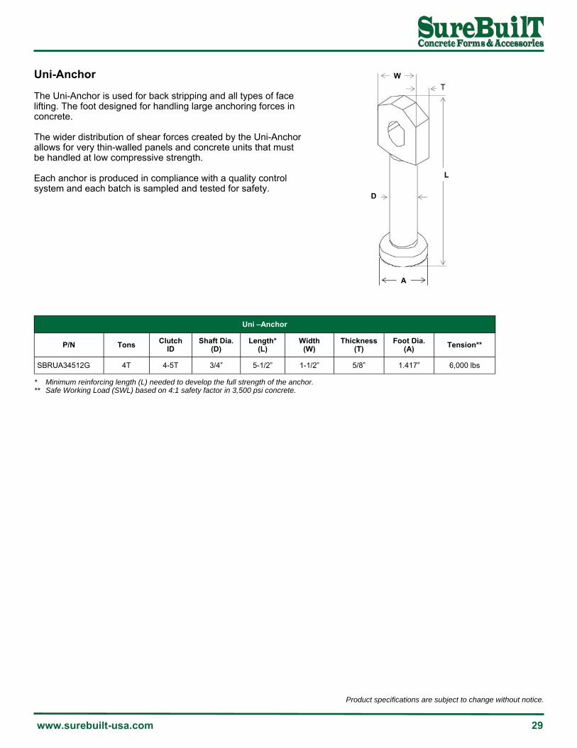
Uni-Anchor The Uni-Anchor is used for back stripping and all types of face lifting. The foot designed for handling large anchoring forces in concrete. The wider distribution of shear forces created by the Uni-Anchor allows for very thin-walled panels and concrete units that must be handled at low compressive strength. Each anchor is produced in compliance with a quality control system and each batch is sampled and tested for safety.
L
D
W
T
A
Uni –Anchor
P/N Tons Clutch ID
Shaft Dia. (D)
Length* (L)
Width (W)
Thickness (T)
Foot Dia. (A) Tension**
SBRUA34512G 4T 4-5T 3/4” 5-1/2” 1-1/2” 5/8” 1.417” 6,000 lbs
* Minimum reinforcing length (L) needed to develop the full strength of the anchor. ** Safe Working Load (SWL) based on 4:1 safety factor in 3,500 psi concrete.

30 Call 708-493-9569
Product specifications are subject to change without notice.
Straight Leg Insert The Straight Leg Insert is designed for back-shipping and rotating segments using standard Ring-Lift hardware. The L-shaped legs are designed for handling large anchoring forces in concrete segments. The insert can be further reinforced by adding rebar over the feet. Each insert includes a one-time disposable plastic void former. An optional reusable steel void former is also available. A wide-leg design, plastic feet, and galvanized finish are also available. Available in black, galvanized (G) and hot-dip galvanized (HDG) finish.
Straight Leg Insert
P/N Tons Clutch ID Height Leg
Thickness Tension*
SBRSL2.5T312 2.5T 2-2.5T 3-1/2” 3/8” 3,900 lbs
SBRSL2.5T512 2.5T 2-2.5T 5-1/2” 3/8” 4,600 lbs
SBRSL5T312 5T 4-5T 3-1/2” 1/2” 4,400 lbs
SBRSL5T412 5T 4-5T 4-1/2” 1/2” 6,200 lbs
SBRSL5T512 5T 4-5T 5-1/2” 5/8” 8,000 lbs
SBRSL5T912 5T 4-5T 9-1/2” 5/8” 11,000 lbs
SBRSL10T512 10T 8-10T 5-1/2” 3/4” 8,800 lbs
SBRSL10T7 10T 8-10T 7” 3/4” 12,500 lbs
SBRSL10T9 10T 8-10T 9” 3/4” 20,000 lbs
SBRSL10T12 10T 8-10T 12” 3/4” 22,000 lbs
* Safe Working Load (SWL) based on 4:1 safety factor in 3,500 psi concrete. Based on full embedment, edge distance 1.5x height, and spacing 3x embedded depth.

Product specifications are subject to change without notice.
www.surebuilt-usa.com 31
Double Tee Anchor The Double Tee Anchor is designed for lifting single or double tee precast concrete segments. The anchor is recessed to eliminate the removal costs associated with other lifting schemes. The design uses 5/8” square or 3/4” round bar for the 8T anchor and 3/4” square or 7/8” round bar for the 10T anchor. The wavy end of the anchor ensures proper engagement in the surrounding concrete.
W
FW
L
B
S - Single D - Double
IW1
W
FW
L
B
IW1
Double Row - InsideAnchor Width: 1-1/4”/ 1-1/2”
Single Row - OutsideAnchor Width: 4”
Double Row - OutsideAnchor Width: 5”
Installation: Wet set or pre-tie in place with the legs parallel to strand.
Installation: Wet set or pre-install over single row of strand. Rotate until DTA legs contact the strand on both sides. Align anchor with center on the tee.
Installation: Wet set or pre-install over double row of strand. Rotate until DTA legs contact the strand on both sides. Align anchor with center on the tee.
Square Bar
Anchor
Single and Double Tee Anchor*
P/N Tons Thickness (B)
Width (FW)
Length (L)
Width (W) Capacity** Ultimate
SBDTA8T23 (S/D) 8T 3/4" Ø 1-1/4” 23” 5” (D) / 4” (S) 16,000 lbs 64,000 lbs
SBDTA10T23 (S/D) 10T 3/4" x 3/4” 1-1/2” 23” 5” (D) / 4” (S) 22,000 lbs 88,000 lbs
* Available in Single (S) and Double (D). Optional zinc finish. ** Safe Working Load (SWL) based on 4:1 safety factor in 6,000 psi concrete. Based on minimum coverage of 3/4” from side of foot to edge of concrete and minimum spacing of 9” from end of beam.

32 Call 708-493-9569
Product specifications are subject to change without notice.
W
L
Wavy Tail Anchor The Wavy Tail Anchor is ideal for lifting pipes, tanks and other thin-wall concrete segments. The 2.5T Ring-Lift lifting hardware The embedded tensile strength of the Wavy Tail Anchor in a slim wall section is noted below. The anchor must be in the center of the segment. Always secure the anchor to the reinforcing or form to maintain the position during concrete placement.
Minimum Corner Distance
T - Panel Thickness
T/2
TC
TC
Proper Lifting Procedure
Wavy Tail Anchor
P/N Tons Clutch ID
Length (L)
Width (W) Capacity*
SBWTA14434 1T 2-2.5T 4-3/4” 1-1/4” 2,000 lbs
* Safe Working Load (SWL) based on 4:1 safety factor in 3,500 psi concrete. Shear capacities are based on lifter casting bearing against concrete.
Wavy Tail Anchor (Length 4-3/4”) Capacity
Panel Thickness
(T) T / 2
Tension*
8” 12”
4” 2” 1,400 lbs 1,600 lbs
5” 2-1/2” 1,700 lbs 2,000 lbs
5 1/2” 2-9/16” 2,000 lbs 2,000 lbs
TC
1.375”
1.875”
1.925”
Shear*
403 lbs
450 lbs
550 lbs
* Safe Working Load (SWL) based on 4:1 safety factor in 3,500 psi concrete. Minimum corner distance is 1.5x anchor length and minimum spacing is 3x anchor length.
Note: When used as a “back-stripping” anchor, the minimum corner distance is 1.5x the anchor length and the minimum distance between adjacent anchors is 3x the anchor length.

Product specifications are subject to change without notice.
www.surebuilt-usa.com 33
Plate Anchor The Plate Anchor is used for face- and back-lifts of thin-walled segments. The low profile and wide, flat base provide excellent anchorage. The welded horizontal plate at the bottom develops high pull-out strength in stripping, handling and erecting segments. Weld
T
A
L
C
Plate Anchor*
P/N Tons Clutch ID
Length (L)
WIidth (A)
Thickness (T)
Plate (C)
Min Edge Distance* Shear** Tension***
SBRPA38214G 2T 2-2.5T 2-1/4” 1-1/4” 3/8” 2-1/2” 4-1/2” 1,100 lbs 1,100 lbs
SBRPA583G 4T 4-5T 3” 1-1/2” 5/8” 3” 6” 3,800 lbs 3,500 lbs
SBRPA58312G 4T 4-5T 3-1/2” 1-1/2” 5/8” 3” 7” 4,700 lbs 4,700 lbs
SBRPA58438G 4T 4-5T 4-3/8” 1-1/2” 5/8” 4” 8” 5,200 lbs 5,200 lbs
SBRPA34512G 8T 8-10T 5-1/2” 2-1/2” 3/4” 4” 12” 6,350 lbs 6,350 lbs
SBRPA34718G 8T 8-10T 7-1/8” 2-1/2” 3/4” 4” 15” 10,000 lbs 10,000 lbs
* Minimum edge distance is 2x embedded depth. ** Safe Working Load (SWL) based on 4:1 safety factor in 3,000 psi concrete. Allowable shear face loads equal to or greater than unreinforced tension loads for anchors located at the minimum edge distance. *** Safe Working Load (SWL) based on 4:1 safety factor in 3,500 psi concrete.

34 Call 708-493-9569
Product specifications are subject to change without notice.
Erection Anchor The Erection Anchor combines reinforcing capabilities with spall-free performance. It is ideal for an A-frame, tilt table or whenever the lift is not straight up. While the shear capacity is less than a standard erection anchor because of the shorter length, the full safe working load can be achieved in thin slabs by using a reinforcement Tension Bar through the second hole. The Erection Anchor head is equal to a standard erection anchor because of the length. The convex sides build better strength without any more material.
Erection Anchor
P/N Tons Clutch ID
Length (L)
Width (W)
Thickness (T)
Tension w/ Tension Bar
SBDEA384G 2T 2-2.5T 4” 2” 3/8” 4,000 lbs
SBDEA587G 4T 4-5T 7” 2-1/2” 5/8” 8,000 lbs
SBDEA5876TG 6T 8-10T 7” 3-1/2” 5/8” 12,000 lbs
SBDEA347G 8T 8-10T 7” 3-1/2” 3/4” 16,000 lbs
SBDEA341312G 8T 8-10T 13-1/2” 3-1/2” 3/4” 16,000 lbs
L
30°
T
W
L
* Safe Working Load (SWL) based on 4:1 safety factor in 3,500 psi concrete.
Tension Bar Length (L) Requirement*
P/N Load Rebar 2,000 psi 3,000 psi 5,000 psi
SBTB2T 2-2.5T #4 2-9” 2’-6” 1’-8”
SBTB4T 4-5T #5 3’-6” 3’-0” 2’-2”
SBTB8T 6-8-10T #6 5’-6” 4’-6” 3’-3”
Concrete Strength
Tension Bar The Tension Bar is used with the Erection Anchor to distribute tension loads into the precast segment.
* Minimum reinforcing length (L) needed to develop the full strength of the anchor.

Product specifications are subject to change without notice.
www.surebuilt-usa.com 35
Erection Anchor with Shear Plate The Erection Anchor combines reinforcing capabilities with spall-free performance. It is ideal for an A-frame, tilt table or whenever the lift is not straight up. While the shear capacity is less than a standard erection anchor because of the shorter length, the full safe working load can be achieved in thin slabs by using a reinforcement Tension Bar through the second hole. The Erection Anchor head is equal to a standard erection anchor because of the length. Convex sides build better strength without any added material. The shear plate replaces the need for a shear bar making it easier to install.
Note: There is load data on the following pages. If higher loads are desired, then a Tension Bar should be placed through the lower hole of the anchor. Consult the Tension Bar chart for rebar length, diameter and bend angle.
Erection Anchor with Shear Plate
P/N Tons Clutch ID
Anchor Dimension Plate Dimension Tension with
Tension Bar* Length (L)
Width (W)
Thick (T)
Width (A)
Position (B)
Length (C)
Thick (D)
SBDEA384SPG 2T 2-2.5T 4” 2” 3/8” 2-1/2” 3/4” 3” 1/4” 4,000 lbs
SBDEA38425TSPG 2.5T 2-2.5T 4” 2” 3/8” 2-1/2” 3/4” 3” 1/4’7” 5,000 lbs
SBDEA587SPG 4T 4-5T 7” 2-1/2” 5/8” 2-1/2” 1-1/4” 3” 3/8” 8,000 lbs
SBDEA347SPG 8T 8-10T 7” 3-1/2” 3/4” 3” 1-5/8” 3-1/2” 3/8” 16,000 lbs
SBDEA341312SPG 8T 8-10T 13-1/2” 3-1/2” 3/4” 3” 1-5/8” 3-1/2” 3/8” 16,000 lbs
L
W
A
C
B
D
T
* Safe Working Load (SWL) based on 4:1 safety factor in 3,500 psi concrete.

36 Call 708-493-9569
Product specifications are subject to change without notice.
Erection Anchor with Shear Plate Load Table
P/N
Tons Clutch
ID Panel
Thickness
Shear Load* With Shear Plate Transport Value
Shear Load* with Shear Plate Tilt-Up Value**
Tension Load* with Tension Bar
SBDEA3842TSPG 2T x 4” 2-2.5T 3-1/2” min 1,325 lbs 1,990 lbs 4,000 lbs
SBDEA3842TSPG 2T x 4” 2-2.5T 4” 1,525 lbs 2,290 lbs 4,000 lbs
SBDEA3842TSPG 2T x 4” 2-2.5T 5” 1,525 lbs 2,290 lbs 4,000 lbs
SBDEA3842TSPG 2T x 4” 2-2.5T 6” 1,750 lbs 2,630 lbs 4,000 lbs
SBDEA3842TSPG 2T x 4” 2-2.5T 7” 1,900 lbs 2,850 lbs 4,000 lbs
SBDEA3842TSPG 2T x 4” 2-2.5T 8” 2,075 lbs 3,120 lbs 4,000 lbs
SBDEA5874TSPG 4T x 7” 4-5T 5-1/2” min 2,025 lbs 3,045 lbs 8,000 lbs
SBDEA5874TSPG 4T x 7” 4-5T 6” 2,250 lbs 3,380 lbs 8,000 lbs
SBDEA5874TSPG 4T x 7” 4-5T 7” 2,600 lbs 3,900 lbs 8,000 lbs
SBDEA5874TSPG 4T x 7” 4-5T 8” 3,000 lbs 4,500 lbs 8,000 lbs
SBDEA5874TSPG 4T x 7” 4-5T 9” 3,375 lbs 5,075 lbs 8,000 lbs
SBDEA5874TSPG 4T x 7” 4-5T 10” 3,750 lbs 5,630 lbs 8,000 lbs
SBDEA3413128TSPG 8T x 13-1/2” 8-10T 7-1/2” min 4,010 lbs 6,030 lbs 16,000 lbs
SBDEA3413128TSPG 8T x 13-1/2” 8-10T 8” 4,010 lbs 6,030 lbs 16,000 lbs
SBDEA3413128TSPG 8T x 13-1/2” 8-10T 9” 4,120 lbs 6,190 lbs 16,000 lbs
SBDEA3413128TSPG 8T x 13-1/2” 8-10T 10” 4,280 lbs 6,430 lbs 16,000 lbs
SBDEA3413128TSPG 8T x 13-1/2” 8-10T 11” 4,420 lbs 6,645 lbs 16,000 lbs
SBDEA3413128TSPG 8T x 13-1/2” 8-10T 12” 4,550 lbs 6,845 lbs 16,000 lbs
* Safe Working Load (SWL) based on 4:1 safety factor with full embedment, reinforcement and 3,500 psi concrete. ** Tilt-Up values can be used for shear if an anchor is used only once for erecting the panel.

Product specifications are subject to change without notice.
www.surebuilt-usa.com 37
X-Foot Erection Anchor The X-Foot Erection Anchor is designed for horizontal to vertical edge lifts and shear rotation of thin-walled units. The specially designed head has two “ears” at the top protect against spalling. These ears hug either side of the ring clutch, restricting its rotation during lateral pulls. As a result, lateral forces are transmitted directly to the edges of the anchor instead of the concrete. The body of the Erection Anchor is shaped to allow full reinforcement for secure support. Because of the stress caused by the shear lift of a thin panel, reinforcement is necessary in the direction of the lift. The full safe working load can be achieved in thin slabs or when there is low concrete strength by using a Tension Bar in the second hole.
X-Foot Erection Anchor
P/N Tons Clutch ID
Width (W)
Length (L)
Thickness (T) Tension*
SBSFEA2TG 2T 2-2.5T 2” 8” 3/8” 4,000 lbs
SBSFEA4TG 4T 4-5T 2-1/2” 9-1/2” 5/8” 8,000 lbs
SBSFEA8TG 8T 8-10T 3-1/2” 13-1/2” 3/4” 16,000 lbs
Note: During rotation the sling angle should be perpendicular to the surface. While the panel is being rotated on its edge, the load can usually be factored by 0.5. During this phase of the lift, the anchors are not bearing the full weight of the panel. The rated loads and minimum panel thicknesses can be found in the accompanying table. Once the panel has been rotated to vertical, the tension lift is initiated.
W T
L
Shear Bar
P/N Tons Clutch ID Height Min Panel
Thickness
SBSB2T 2T 2-2.5T 2-1/2” 4”
SBSB4T 4T 4-5T 3-5/16” 5-1/2”
SBSB8T 8T 8-10T 4-15/16” 7-1/2”
Shear Bar The Shear Bar is used with the Erection Anchor to distribute tension loads into the precast segment. The bar is stronger, less expensive, and easier to use than fabricated rebar.
* Safe Working Load (SWL) based on 4:1 safety factor in 3,500 psi concrete.
38 Call 708-493-9569
Product specifications are subject to change without notice.
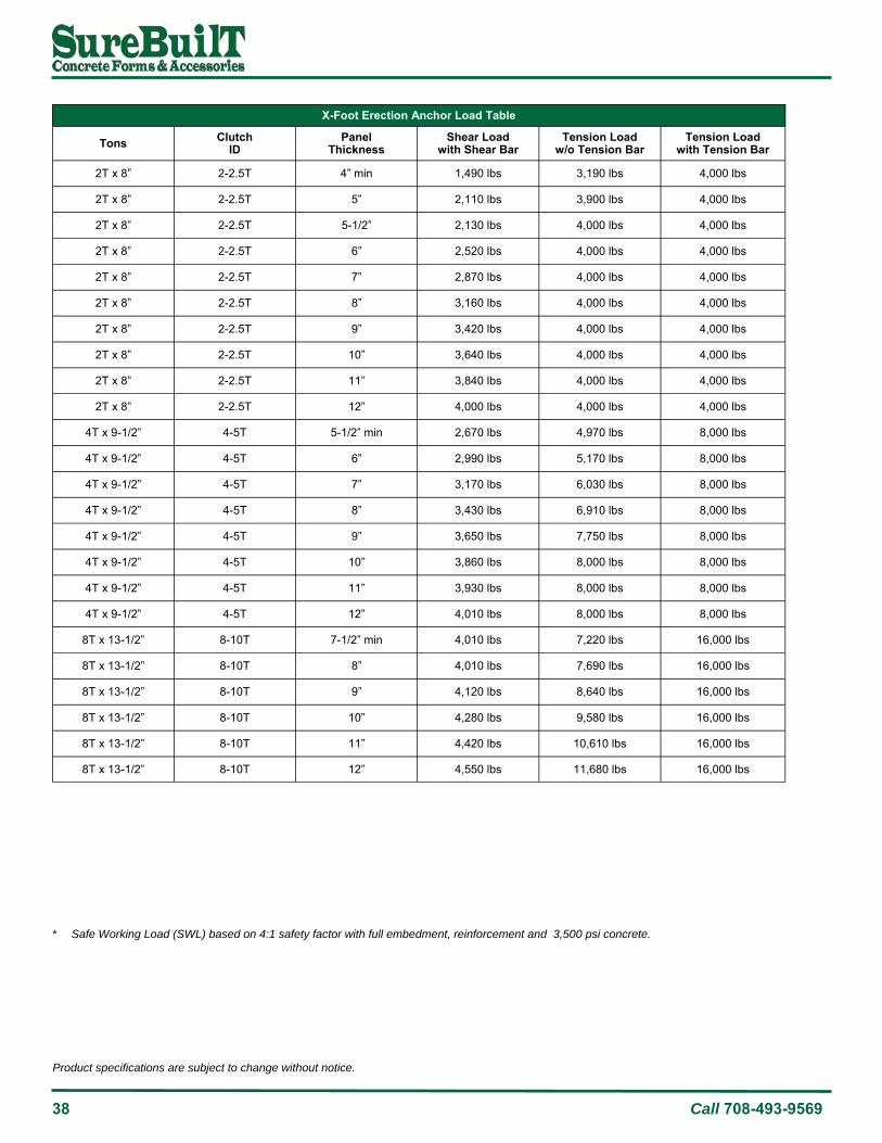
X-Foot Erection Anchor Load Table
Tons Clutch ID
Panel Thickness
Shear Load with Shear Bar
Tension Load w/o Tension Bar
Tension Load with Tension Bar
2T x 8” 2-2.5T 4” min 1,490 lbs 3,190 lbs 4,000 lbs
2T x 8” 2-2.5T 5” 2,110 lbs 3,900 lbs 4,000 lbs
2T x 8” 2-2.5T 5-1/2” 2,130 lbs 4,000 lbs 4,000 lbs
2T x 8” 2-2.5T 6” 2,520 lbs 4,000 lbs 4,000 lbs
2T x 8” 2-2.5T 7” 2,870 lbs 4,000 lbs 4,000 lbs
2T x 8” 2-2.5T 8” 3,160 lbs 4,000 lbs 4,000 lbs
2T x 8” 2-2.5T 9” 3,420 lbs 4,000 lbs 4,000 lbs
2T x 8” 2-2.5T 10” 3,640 lbs 4,000 lbs 4,000 lbs
2T x 8” 2-2.5T 11” 3,840 lbs 4,000 lbs 4,000 lbs
2T x 8” 2-2.5T 12” 4,000 lbs 4,000 lbs 4,000 lbs
4T x 9-1/2” 4-5T 5-1/2” min 2,670 lbs 4,970 lbs 8,000 lbs
4T x 9-1/2” 4-5T 6” 2,990 lbs 5,170 lbs 8,000 lbs
4T x 9-1/2” 4-5T 7” 3,170 lbs 6,030 lbs 8,000 lbs
4T x 9-1/2” 4-5T 8” 3,430 lbs 6,910 lbs 8,000 lbs
4T x 9-1/2” 4-5T 9” 3,650 lbs 7,750 lbs 8,000 lbs
4T x 9-1/2” 4-5T 10” 3,860 lbs 8,000 lbs 8,000 lbs
4T x 9-1/2” 4-5T 11” 3,930 lbs 8,000 lbs 8,000 lbs
4T x 9-1/2” 4-5T 12” 4,010 lbs 8,000 lbs 8,000 lbs
8T x 13-1/2” 8-10T 7-1/2” min 4,010 lbs 7,220 lbs 16,000 lbs
8T x 13-1/2” 8-10T 8” 4,010 lbs 7,690 lbs 16,000 lbs
8T x 13-1/2” 8-10T 9” 4,120 lbs 8,640 lbs 16,000 lbs
8T x 13-1/2” 8-10T 10” 4,280 lbs 9,580 lbs 16,000 lbs
8T x 13-1/2” 8-10T 11” 4,420 lbs 10,610 lbs 16,000 lbs
8T x 13-1/2” 8-10T 12” 4,550 lbs 11,680 lbs 16,000 lbs
* Safe Working Load (SWL) based on 4:1 safety factor with full embedment, reinforcement and 3,500 psi concrete.

Product specifications are subject to change without notice.
www.surebuilt-usa.com 39
X-Foot Erection Anchor with Shear Plate The X-Foot Erection Anchor with Shear Plate is designed for horizontal-to-vertical edge lifts and shear rotation of thin-walled units. The welded shear plate replaces the need for a shear bar, reducing the number of components needed and making it easier to install. No special ring clutch is necessary, The specially designed head has two “ears” at the top protect against spalling. These ears hug either side of the ring clutch, restricting its rotation during lateral pulls. As a result, lateral forces are transmitted directly to the edges of the anchor instead of the concrete. The body of the Erection Anchor is shaped to allow full reinforcement for secure support. Because of the stress caused by the shear lift of a thin panel, reinforcement is necessary in the direction of the lift. The full safe working load can be achieved in thin slabs or when there is low concrete strength by using a Tension Bar in the second hole.
W
L
T
A
C
B
D
X-Foot Erection Anchor w/ Shear Plate
P/N Tons Clutch ID
X-Foot Dimension Shear Plate Dimension
Tension Width
(W) Length
(L) Thickness
(T) Width
(A) From Top
(B) Length
(C) Thickness
(D)
SBSFEA2TPG 2T 2-2.5T 2” 8” 3/8” 2-1/2” 3/4” 3” 1/4” 4,000 lbs
SBSFEA4TPG 4T 4-5T 2-1/2” 9-1/2” 5/8” 2-1/2” 1-1/4” 3” 3/8” 8,000 lbs
SBSFEA8TPG 8T 8-10T 3-1/2” 13-1/2” 3/4” 3” 1-5/8” 3-1/2” 3/8” 16,000 lbs
* Safe Working Load (SWL) based on 4:1 safety factor in 3,500 psi concrete.
Note: During rotation the sling angle should be perpendicular to the surface. While the panel is being rotated on its edge, the load can usually be factored by 0.5. During this phase of the lift, the anchors are not bearing the full weight of the panel. The rated loads and minimum panel thicknesses can be found in the accompanying table. Once the panel has been rotated to vertical, the tension lift is initiated.

40 Call 708-493-9569
Product specifications are subject to change without notice.
X-Foot Erection Anchor w/ Shear Plate Load Table
Tons Clutch ID
Panel Thickness
Shear Load with Shear Plate
Tension Load w/o Tension Bar
Tension Load with Tension Bar
2T x 8” 2-2.5T 3-1/2” min 1,490 lbs 2,640 lbs 4,000 lbs
2T x 8” 2-2.5T 4” 1,940 lbs 3,190 lbs 4,000 lbs
2T x 8” 2-2.5T 5” 2,110 lbs 3,900 lbs 4,000 lbs
2T x 8” 2-2.5T 5-1/2” 2,130 lbs 4,000 lbs 4,000 lbs
2T x 8” 2-2.5T 6” 2,520 lbs 4,000 lbs 4,000 lbs
2T x 8” 2-2.5T 7” 2,870 lbs 4,000 lbs 4,000 lbs
2T x 8” 2-2.5T 8” 3,160 lbs 4,000 lbs 4,000 lbs
2T x 8” 2-2.5T 9” 3,420 lbs 4,000 lbs 4,000 lbs
2T x 8” 2-2.5T 10” 3,640 lbs 4,000 lbs 4,000 lbs
2T x 8” 2-2.5T 11” 3,840 lbs 4,000 lbs 4,000 lbs
2T x 8” 2-2.5T 12” 4,000 lbs 4,000 lbs 4,000 lbs
4T x 9-1/2” 4-5T 4” min 1,800 lbs 3,400 lbs 8,000 lbs
4T x 9-1/2” 4-5T 5-1/2” 2,670 lbs 4,970 lbs 8,000 lbs
4T x 9-1/2” 4-5T 6” 2,990 lbs 5,170 lbs 8,000 lbs
4T x 9-1/2” 4-5T 7” 3,170 lbs 6,030 lbs 8,000 lbs
4T x 9-1/2” 4-5T 8” 3,430 lbs 6,910 lbs 8,000 lbs
4T x 9-1/2” 4-5T 9” 3,650 lbs 7,750 lbs 8,000 lbs
4T x 9-1/2” 4-5T 10” 3,860 lbs 8,000 lbs 8,000 lbs
4T x 9-1/2” 4-5T 11” 3,930 lbs 8,000 lbs 8,000 lbs
4T x 9-1/2” 4-5T 12” 4,010 lbs 8,000 lbs 8,000 lbs
8T x 13-1/2” 8-10T 7” min 4,010 lbs 7,100 lbs 16,000 lbs
8T x 13-1/2” 8-10T 7-1/2” 4,010 lbs 7,220 lbs 16,000 lbs
8T x 13-1/2” 8-10T 8” 4,010 lbs 7,690 lbs 16,000 lbs
8T x 13-1/2” 8-10T 9” 4,120 lbs 8,640 lbs 16,000 lbs
8T x 13-1/2” 8-10T 10” 4,280 lbs 9,580 lbs 16,000 lbs
8T x 13-1/2” 8-10T 11” 4,420 lbs 10,610 lbs 16,000 lbs
8T x 13-1/2” 8-10T 12” 4,550 lbs 11,680 lbs 16,000 lbs
* Safe Working Load (SWL) based on 4:1 safety factor with full embedment, reinforcement and 3,500 psi concrete.

Product specifications are subject to change without notice.
www.surebuilt-usa.com 41
X-Foot Erection Anchor w/ 45° Miter and Shear Plate *
P/N Tons Clutch ID
Width (W)
Length (L)
Thickness (T)
Panel Thickness Shear** Tension**
w/Tension Bar
SBSFEA2TMTRSPG 2T 2-2.5T 2” 8-1/2” 3/8” 6-1/2” 2,150 lbs 3,400 lbs
SBSFEA4TMTRSPG 4T 4-5T 2-1/2” 11-1/8” 5/8” 8” 3,500 lbs 5,400 lbs
SBSFEA8TMTRSPG 8T 8-10T 3-3/4” 13-3/4” 3/4” 8” min 3,500 lbs 6,200 lbs
Mitered X-Foot Erection Anchor with Shear Plate When the lifting edge is beveled at a 45° angle, the mitered X-Foot Erection Anchor with Shear Plate is needed. The factory miter the concrete design and the and shear plate eliminates the need for any shear reinforcement. This makes it easier to install. No special clutch is necessary. The specially designed head has two “ears” at the top protect against spalling. These ears hug either side of the ring clutch, restricting its rotation during lateral pulls. As a result, lateral forces are transmitted directly to the edges of the anchor instead of the concrete. The body of the Erection Anchor is shaped to allow full reinforcement for secure support. Because of the stress caused by the shear lift of a thin panel, reinforcement is necessary in the direction of the lift. The full safe working load can be achieved in thin slabs or when there is low concrete strength by using a Tension Bar in the second hole.
Note: To install the X-Foot Erection Anchor with 45° Miter and Shear Plate, position the anchor a minimum of 3/4” and a maximum of 1-1/2” clear of the casting bed. After the anchor has been fastened in place, tension reinforcement may be added as needed. After the concrete has set, removal of the edge form and recess member will expose the head of the anchor for attachment of the lifting eye.
3/4” min - 1-1/2” max
L
T
2”
3”
* The concrete panel will not hang plumb when using the mitered anchor. Do not exceed the safe working load. ** Safe Working Load (SWL) based on 4:1 safety factor in 3,500 psi concrete.
W

42 Call 708-493-9569
Product specifications are subject to change without notice.
Shear Bar The Shear Bar is used with the X-Foot Erection Anchor to distribute tension loads into the precast segment. The bar is stronger, less expensive, and easier to use than fabricated rebar. The Shear Bar provides economical reinforcement for the X-Foot Erection Anchor during the rotation phase of edge lifts. The loop on the shear bar fits over the anchor to spread shear stress over a wide area and deep into the concrete.
L
30°
Tension
Shear
A
L
Shear Bar
P/N Tons Clutch ID
Height (A)
Min Panel Thickness
SBSB2T 2T 2-2.5T 2-1/2” 4”
SBSB4T 4T 4-5T 3-5/16” 5-1/2”
SBSB8T 8T 8-10T 4-15/16” 7-1/2”
Length (L)
13-7/8”
13-7/8”
13-7/8”
Tension Bar Length (L) Requirement*
P/N Load Rebar 2,000 psi 3,000 psi 5,000 psi
SBTB2T 2T #4 2-9” 2’-6” 1’-8”
SBTB4T 4T #5 3’-6” 3’-0” 2’-2”
SBTB8T 8T #6 5’-6” 4’-6” 3’-3”
Concrete Strength
Tension Bar The Tension Bar is used with the X-Foot Erection Anchor to distribute tension loads into the precast segment.
* Minimum reinforcing length (L) needed to develop the full strength of the anchor.

Product specifications are subject to change without notice.
www.surebuilt-usa.com 43
Straight Leg Erection Anchor with Shear Plate The Straight Leg Erection Anchor is ideal for horizontal-to-vertical edge lifts and shear rotation of thin-walled segments. The anchor is easier to install because the shear plate eliminates the need for an added shear bar. Two steel “ears” on the head of the anchor provides protection against spalling. The ears hug the Ring-Lift hardware, restricting rotation during lateral pulls. The lateral forces are transmitted to the edges of the anchor instead of the concrete. The shape of the Straight Leg Erection Anchor allows full reinforcement support and spall-free rotation during handling.
L
T W
Straight Leg Erection Anchor with Shear Plate
P/N Tons Width (W)
Thickness (T)
Length (L)
Panel Thickness
Shear* w/o Shear Bar
Tension* w/o Tension Bar
Tension* w/ Tension Bar
SBSLE2TSPG 2T 2-3/8” 3/8” 8”
4” (min) 1,800 lbs 3,190 lbs 4,400 lbs
5” 2,000 lbs 3,900 lbs 4,400 lbs
5-1/2” 2,400 lbs 4,000 lbs 4,400 lbs
6” 2,800 lbs 4,000 lbs 4,400 lbs
7” 3,300 lbs 4,400 lbs 4,400 lbs
8” 3,600 lbs 4,400 lbs 4,400 lbs
9” 3,800 lbs 4,400 lbs 4,400 lbs
10” 4,000 lbs 4,400 lbs 4,400 lbs
11” 4,200 lbs 4,400 lbs 4,400 lbs
12” 4,400 lbs 4,400 lbs 4,400 lbs
SBSLE4TSPG 4T 3-1/16” 5/8” 10-1/2”
5-1/2” (min) 3,100 lbs 4,970 lbs 8,800 lbs
6” 3,200 lbs 5,170 lbs 8,800 lbs
7” 3,700 lbs 6,030 lbs 8,800 lbs
8” 4,000 lbs 6,910 lbs 8,800 lbs
9” 4,300 lbs 7,750 lbs 8,800 lbs
10” 4,600 lbs 8,000 lbs 8,800 lbs
11” 5,000 lbs 8,800 lbs 8,800 lbs
12” 5,000 lbs 8,800 lbs 8,800 lbs
SBSLE8TSPG 8T 3-5/8” 3/4”
7-1/2” (min) 4,300 lbs 7,500 lbs 20,000 lbs
8” 4,500 lbs 7,690 lbs 20,000 lbs
9” 5,000 lbs 8,640 lbs 20,000 lbs
10” 5,500 lbs 9,580 lbs 20,000 lbs
11” 6,200 lbs 11,500 lbs 20,000 lbs
12” 6,900 lbs 13,200 lbs 20,000 lbs
13-1/2”
* Safe Working Load (SWL) based on 4:1 safety factor in 3,500 psi concrete. Based on full embedment and added reinforcement as noted.

44 Call 708-493-9569
Product specifications are subject to change without notice.
Drop-Forged Foot Erection Anchor The Drop-Forged Foot Erection Anchor has a specially designed shape that make it easier to install without reducing the load capacity for concrete edge lifts. The protrusions or “ears” at the top of the anchor restrict rotation during lifting, protecting the concrete from spalling. The body is shaped to allow for full panel reinforcement, providing support during lifting. The integrated foot eliminates the need for an additional shear bar, simplifying the anchor installation. During panel rotation, the sling angle should always be perpendicular to the surface or the anchors will not be bearing the full weight of the panel. Once the panel has been rotated to vertical, the tension is initiated. During this phase, the drop-forged foot at the bottom of the anchor, develops a tension load.
Drop-Forged Foot Erection Anchor*
P/N Anchor Lifter Width Length Plate Tension**
SBDFFEA5TG 5 Ton 4-5 Ton 3-1/2” 10” 2-1/2”x3” 11,000 lbs
SBDFFEA10TG 10 Ton 8-10 Ton 4-1/2” 12-1/2” 3”x4” 22,200 lbs
* Anchor is designed to match the capacity of the 5-Ton and 10-Ton Ring-Lift hardware. ** Safe Working Load (SWL) based on 4:1 safety factor in 3,500 psi concrete.

Product specifications are subject to change without notice.
www.surebuilt-usa.com 45
Drop-Forged Foot Erection Anchor Load Table
Anchor Lifter Panel Thickness
Shear Load (no Shear Bar)
Transport Value*
Shear Load (no Shear Bar) Tilt-Up Value**
Tension Load w/o
Tension Bar*
Tension Load With
Tension Bar***
5 Ton 4-5 Ton 5-1/2” min 2,950 lbs 4,020 lbs 5,750 lbs 11,000 lbs
5 Ton 4-5 Ton 6” 3,200 lbs 4,200 lbs 7,200 lbs 11,000 lbs
5 Ton 4-5 Ton 7” 3,400 lbs 4,670 lbs 8,000 lbs 11,000 lbs
5 Ton 4-5 Ton 8” 3,800 lbs 5.454 lbs 10,200 lbs 11,000 lbs
5 Ton 4-5 Ton 9” 4,400 lbs 6,212 lbs 11,000 lbs 11,000 lbs
5 Ton 4-5 Ton 10” 4,800 lbs 6,818 lbs 11,000 lbs 11,000 lbs
5 Ton 4-5 Ton 11” 5,200 lbs 7,272 lbs 11,000 lbs 11,000 lbs
5 Ton 4-5 Ton 12” 6,100 lbs 7,575 lbs 11,000 lbs 11,000 lbs
10 Ton 8-10 Ton 7-1/2” min 4,600 lbs 6,363 lbs 17,500 lbs 22,000 lbs
10 Ton 8-10 Ton 8” 4,800 lbs 6,666 lbs 17,500 lbs 22,000 lbs
10 Ton 8-10 Ton 9” 5,450 lbs 7,272 lbs 18,000 lbs 22,000 lbs
10 Ton 8-10 Ton 10” 6,100 lbs 7,878 lbs 19,000 lbs 22,000 lbs
10 Ton 8-10 Ton 11” 6,800 lbs 8,333 lbs 20,000 lbs 22,000 lbs
10 Ton 8-10 Ton 12” 7,600 lbs 8,787 lbs 22,000 lbs 22,000 lbs
* Safe Working Load (SWL) based on 4:1 safety factor in 3,500 psi concrete. ** Tilt-Up Value can be used for shear if an anchor is used only once for erecting the panel. *** Given full embedment, reinforcement and minimum compressive strength, the anchor should achieve pullout strength equal to
the maximum tension strength with a Tension Bar. panel.

46 Call 708-493-9569
Product specifications are subject to change without notice.
HD Sandwich Panel Erection Anchor By delivering an even load distribution to both sides of a sandwich panel, the Sandwich Panel Erection Anchor transfers the highest loads on panel edge without shear bars. The anchor is easy to install and the design absorbs shear loads without spalling concrete. Additional shear reinforcement can be added if necessary to increase the shear capacity. Given full embedment, reinforcement, and a minimum compressive strength of 4,500 psi, the 8T Sandwich Panel Erection Anchors will achieve a pullout strength equal to the ultimate strength when reinforced with two #6 x3’-6" long bent bars.
C L
D
B
A
3
3
4
(1)
(2)
(2)
HD Sandwich Panel Erection Anchor for 9” Panel (3”x3”x3”)
Tons Tension Shear
Parallel to Thickness*
Shear Parallel to
Thickness**
Shear Perpendicular to
Thickness**
8T 17,600 lbs 5,700 lbs 4,200 lbs 9,400 lbs
10T 20,000 lbs 5,700 lbs 4,200 lbs 10,500 lbs
* Safe Working Load (SWL) based on 2.66:1 safety factor. ** Safe Working Load based on 4:1 safety factor with 24” rebar #5 through holes (1.). (2) Additional shear bar can be placed alongside anchor to increase loading.
HD Sandwich Panel Erection Anchor for 10” Panel (4”x3”x3”)
Tons Tension Shear
Parallel to Thickness*
Shear Parallel to
Thickness**
Shear Perpendicular to
Thickness**
8T 17,600 lbs 7,200 lbs 4,800 lbs 10,500 lbs
10T 20,000 lbs 7,200 lbs 4,800 lbs 10,500 lbs
* Safe Working Load (SWL) based on 2.66:1 safety factor. ** Safe Working Load based on 4:1 safety factor with 24” rebar #5 through holes (1). (2) Additional shear bar can be placed alongside anchor to increase loading.
Notes: 1 The 4:1 safety factor is used with precast work and normally requires no increases except for cable magnification. Additional increases due to unusual
live loads or cable magnification may be required for some applications. 2. The 2.66:1 safety factor, is a 2:1 safety factor, which is commonly used when back shipping, increased 33% to compensate for initial bond and
impact. Additional increases due to unusual live loads or cable magnification may be required for some applications.
HD Sandwich Panel Erection Anchor
P/N Tons Clutch ID
Dimensions
L A B C D
Plasma-Cut HD Sandwich Panel Erection Anchor 8T
SBPCSPEA346G 8T 8-10T 6” 3-3/4” 2-29/32” 3/4” 4”
Drop-Forged HD Sandwich Panel Erection Anchor 10T
SBDFSPEA346G 10T 8-10T 6” 3-3/4” 2-29/32” 3/4” 4”
Insulation Erection
Shear Load
(1)
(2)
(2)
Top Thickness
Bottom Thickness

Product specifications are subject to change without notice.
www.surebuilt-usa.com 47
HD Sandwich Panel Erection Anchor wShear Plate By delivering an even load distribution to both sides of a sandwich panel, the Sandwich Panel Erection Anchor with Shear Plate transfers the highest loads on panel edge without shear bars. The anchor is easy to install and the design absorbs shear loads without spalling concrete. Additional shear reinforcement can be added if necessary to increase the shear capacity. Given full embedment, reinforcement, and a minimum compressive strength of 4,500 psi, the 10T Sandwich Panel Erection Anchors will achieve a pullout strength equal to the ultimate strength when reinforced with two #6 x3’-6" long bent bars.
HD Sandwich Panel Erection Anchor wShear Plate
P/N Tons Clutch ID L A B C D E F
Plasma-Cut HD Sandwich Panel Erection Anchor wShear Plate 8T
SBPCSPEA346SPG 8T 8-10T 6” 3-3/4” 2-29/32” 3/4” 4” 3” 3-1/2”
Drop-Forged HD Sandwich Panel Erection Anchor wShear Plate 10T
SBDFSPEA346SPG 10T 8-10T 6” 3-3/4” 2-29/32” 3/4” 4” 3” 3-1/2”
Dimensions
HD Sandwich Panel Erection Anchor wShear Plate for 9” Panel (3”x3”x3”)
Tons Tension Shear
Parallel to Thickness*
Shear Parallel to
Thickness**
Shear Perpendicular to
Thickness**
8T 17,600 lbs 5,700 lbs 4,200 lbs 9,400 lbs
10T 20,000 lbs 5,700 lbs 4,200 lbs 10,500 lbs
* Safe Working Load (SWL) based on 2.66:1 safety factor. ** Safe Working Load based on 4:1 safety factor with 24” rebar #5 through holes.
HD Sandwich Panel Erection Anchor wShear Plate for 10” Panel (4”x3”x3”)
Tons Tension Shear
Parallel to Thickness*
Shear Parallel to
Thickness**
Shear Perpendicular to
Thickness**
10T 20,000 lbs 7,200 lbs 4,800 lbs 10,500 lbs
8T 17,600 lbs 5,700 lbs 4,200 lbs 9,400 lbs
* Safe Working Load (SWL) based on 2.66:1 safety factor. ** Safe Working Load based on 4:1 safety factor with 24” rebar #5 through holes.

48 Call 708-493-9569
Product specifications are subject to change without notice.
Sandwich Panel Erection Anchor By delivering an even load distribution to both sides of a sandwich panel, the Sandwich Panel Erection Anchor eliminates the need for special lifting devices. This easy-to-install anchor eliminates the need for special spreader bars, distributes the load evenly and absorbs shear loads without spalling concrete.
Notes: 1. The 4:1 safety factor is used with precast work and normally requires no increases except for cable magnification. 2. Given full embedment, reinforcement, and a minimum compressive strength of 3,300 psi, the 4-5 ton Sandwich Panel Erection Anchors should
achieve a pullout strength equal to their Ultimate Mechanical Strength if reinforced with (2) #3 x2'-6" long bent. 3. Given full embedment, reinforcement, and a minimum compressive strength of 4,500 psi, the 8-10 ton Sandwich Panel Erection Anchors should
achieve a pullout strength equal to their Ultimate Mechanical Strength if reinforced with (2) #5 x3’-6" long bent. 4. The 2.66:1 safety factor, is a 2:1 safety factor, which is commonly used when back shipping, increased 33% to compensate for initial bond and
impact. Additional increases due to unusual live loads or cable magnification may be required for some applications.
C L
D
B
A
2
2
4
SPEA346G
Sandwich Panel Erection Anchor
P/N Ton Clutch ID L A B C D
SBSPEA586G 4T 4-5T 6” 3-1/2” 1-3/8” 5/8” 3-3/4”
SBSPEA346G 8T 8-10T 6” 3-3/4” 2-29/32” 3/4” 4’
Sandwich Panel Erection Anchor for 8” Thickness (3”x2”x3”)
Tons Tension* Shear
Parallel to Thickness**
Shear Perpendicular to
Thickness*
4T 8,000 lbs 4,500 lbs 8,000 lbs
8T 16,000 lbs 5,170 lbs 9,400 lbs
Sandwich Panel Erection Anchor for 8” Thickness (4”x2”x2”)
Tons Tension* Shear
Parallel to Thickness**
Shear Perpendicular to
Thickness*
4T 8,000 lbs 4,950 lbs 8,000 lbs
8T 16,000 lbs 5,200 lbs 10,500 lbs
* Safe Working Load (SWL) based on 4:1 safety factor in 3,500 psi concrete. ** Safe Working Load (SWL) based on 2.66:1 safety factor in 3,500 psi concrete.
Insulation
Erection Shear Load Bottom Thickness
Top Thickness
* Safe Working Load (SWL) based on 4:1 safety factor in 3,500 psi concrete. ** Safe Working Load (SWL) based on 2.66:1 safety factor in 3,500 psi concrete.

Product specifications are subject to change without notice.
www.surebuilt-usa.com 49
Sandwich Panel Erection Anchor for 9” Thickness (3”x3”x3”)
Tons Tension* Shear
Parallel to Thickness**
Shear Perpendicular to
Thickness*
8T 16,000 lbs 5,170 lbs 9,400 lbs
Sandwich Panel Erection Anchor for 9” Thickness (3”x4”x3”)
Tons Tension* Shear
Parallel to Thickness**
Shear Perpendicular to
Thickness*
8T 16,000 lbs 5,170 lbs 9,400 lbs
Sandwich Panel Erection Anchor for 10” Thickness (4”x3”x3”)
Tons Tension* Shear
Parallel to Thickness**
Shear Perpendicular to
Thickness*
8T 16,000 lbs 5,170 lbs 9,400 lbs
Sandwich Panel Erection Anchor for 10” Thickness (3”x3”x4”)
Tons Tension* Shear
Parallel to Thickness**
Shear Perpendicular to
Thickness*
8T 16,000 lbs 5,200 lbs 10,500 lbs
Sandwich Panel Erection Anchor - 8 Ton
P/N Panel Thickness Levels L B C D E
SBSPEA346G 8” 3x2x3 6” 3” 3/4” 3-3/4” 3”
SBSPEA346G 8” 4x2x2 6” 3” 3/4” 3-3/4” 4”
SBSPEA347G 9” 3x3x3 7” 3” 3/4” 5” 3-3/4”
SBSPEA348G 10” 3x4x3 8” 3” 3/4” 6” 4-3/4”
SBSPEA34812G 10” 3x4x3 8-1/2” 3” 3/4” 6” 4-3/4”
SBSPEA34812G 10” 4x3x3 8-1/2” 3” 3/4” 6” 4-3/4”
SBSPEA34834G 12” 6x3x3 8-3/4” 2-7/8” 3/4” 6-1/4” 5-3/4”
SBSPEA34812G 10” 3x3x4 8-1/2” 3” 3/4” 6” 4-3/4”
SBSPEA34834G 12” 3x3x6 8-3/4” 2-7/8” 3/4” 6-1/4” 5-3/4”
C
L
D
B
E
SPEA347G
SPEA34812G
3 to 4”
3 to 4”
SPEA34812G
3 to 4”
3 to 5”
SPEA348G
3 to 5”

50 Call 708-493-9569
Product specifications are subject to change without notice.
Sandwich Panel Erection Anchor for 12” Thickness (6”x3”x3”)
Tons Tension* Shear
Parallel to Thickness**
Shear Perpendicular to
Thickness*
8T 16,000 lbs 5,170 lbs 10,900 lbs
Sandwich Panel Erection Anchor for 12” Thickness (3”x3”x6”)
Tons Tension* Shear
Parallel to Thickness**
Shear Perpendicular to
Thickness*
8T 16,000 lbs 5,400 lbs 11,500 lbs
Mitered Sandwich Panel Erection Anchor For 10” Thickness (4”x3”x3”)
Tons Tension* Shear
Parallel to Thickness**
Shear Perpendicular to
Thickness*
8T 16,000 lbs 5,170 lbs 9,400 lbs
Mitered Sandwich Panel Erection Anchor For 12” Thickness (6”x3”x3”)
Tons Tension* Shear
Parallel to Thickness**
Shear Perpendicular to
Thickness*
8T 16,000 lbs 5,170 lbs 11,500 lbs
SPEA34834G SPEA34834G
SPEA34812MG SPEA34834MG
Notes: 1. The 4:1 safety factor is used with precast work and normally requires no increases except for cable magnification. 2. Given full embedment, reinforcement, and a minimum compressive strength of 3,300 psi, the 4-5 ton Sandwich Panel Erection Anchors should
achieve a pullout strength equal to their Ultimate Mechanical Strength if reinforced with (2) #3 x2'-6" long bent. 3. Given full embedment, reinforcement, and a minimum compressive strength of 4,500 psi, the 8-10 ton Sandwich Panel Erection Anchors should
achieve a pullout strength equal to their Ultimate Mechanical Strength if reinforced with (2) #5 x3’-6" long bent. 4. The 2.66:1 safety factor, is a 2:1 safety factor, which is commonly used when back shipping, increased 33% to compensate for initial bond and
impact. Additional increases due to unusual live loads or cable magnification may be required for some applications.
* Safe Working Load (SWL) based on 4:1 safety factor in 3,500 psi concrete. ** Safe Working Load (SWL) based on 2.66:1 safety factor in 3,500 psi concrete.

Product specifications are subject to change without notice.
www.surebuilt-usa.com 51
Sandwich Panel Erection Anchor with Shear Plate for 8” Thickness (3”x2”x3”)
Tons Erection Shear** Tension*
4T 4,800 lbs 8,000 lbs
8T 5,300 lbs 16,000 lbs
Sandwich Panel Erection Anchor with Shear Plate for 9” Thickness (3”x3”x3”)
Tons Erection Shear** Tension*
4T 5,100 lbs 8,000 lbs
8T 5,700 lbs 16,000 lbs
Sandwich Panel Erection Anchor with Shear Plate for 10” Thickness (3-1/2”x2”x3-1/2”)
Tons Erection Shear** Tension*
4T 5.500 lbs 8,000 lbs
8T 6,500 lbs 16,000 lbs
Sandwich Panel Erection Anchor with Shear Plate for 12” Thickness (4”x4”x4”)
Tons Erection Shear** Tension*
4T 5,800 lbs 8,000 lbs
8T 7,200 lbs 16,000 lbs
Sandwich Panel Erection Anchor with Shear Plate By delivering an even load distribution to both sides of a sandwich panel, the Sandwich Panel Erection Anchor eliminates the need for special lifting devices. This easy-to-install anchor eliminates the need for special spreader bars, distributes the load evenly and absorbs shear loads without spalling concrete.
Sandwich Panel Erection Anchor with Shear Plate
P/N Tons Clutch ID
Anchor Plate
(A) (L) (C) (D) (E)
SBSPEA586SPG 4T 4-5T 6” 3-1/2” 5/8” 3/8” 3”x3”
SBSPEA346SPG 8T 8-10T 6” 3-3/4” 3/4” 3/8” 3”x4”
A
C
D
L
E
Insulation
Erection Shear Load
Top Thickness
Bottom Thickness
* Safe Working Load (SWL) based on 4:1 safety factor in 3,500 psi concrete. ** Safe Working Load (SWL) based on 2.66:1 safety factor in 3,500 psi concrete.

52 Call 708-493-9569
Product specifications are subject to change without notice.
Sandwich Panel Erection Anchor with Shear Plate for 9” Thickness (3”x3”x3”)
Tons Tension* Shear
Parallel to Thickness**
Shear Perpendicular to
Thickness*
8T 16,000 lbs 5,700 lbs 9,400 lbs
Sandwich Panel Erection Anchor with Shear Plate for 10” Thickness (3”x4”x3”)
Tons Tension* Shear
Parallel to Thickness**
Shear Perpendicular to
Thickness*
8T 16,000 5,700 lbs 9,400 lbs
Sandwich Panel Erection Anchor with Shear Plate for 10” Thickness (4”x3”x3”)
Tons Tension* Shear
Parallel to Thickness**
Shear Perpendicular to
Thickness*
8T 16,000 lbs 5,700 lbs 10,500 lbs
Sandwich Panel Erection Anchor with Shear Plate for 10” Thickness (3”x3”x4”)
Tons Tension* Shear
Parallel to Thickness**
Shear Perpendicular to
Thickness*
8T 16,000 lbs 5,700 lbs 10,500 lbs
Sandwich Panel Erection Anchor with Shear Plate—8 Ton
P/N Panel Level L A B C D E
SBSPEA346SPG 8” 3”x2”x3” 6” 4-3/4” 3” 3/4” 3-3/4” 3”
SBSPEA346SPG 8” 4”x2”x2” 6” 4-3/4” 3” 3/4” 3-3/4” 4”
SBSPEA347SPG 9” 3”x3”x3” 7” 4-3/4” 3” 3/4” 5” 3-3/4”
SBSPEA348SPG 10” 3”x4”x3” 8” 4-3/4” 3” 3/4” 6” 4-3/4”
SBSPEA34812SPG 10” 3”x4”x3” 8-1/2” 4-3/4” 3” 3/4” 6” 4-3/4”
SBSPEA34812SPG 10” 4”x3”x3” 8-1/2” 4-3/4” 3” 3/4” 6” 4-3/4”
SBSPEA34812SPG 10” 3”x3”x4” 8-1/2” 4-3/4” 3” 3/4” 6” 4-3/4”
SBSPEA34834SPG 12” 6”x3”x3” 8-3/4” 5” 2-7/8” 3/4” 6-1/4” 5-3/4”
SBSPEA34834SP2G 12” 3”x3”x6” 8-3/4” 5” 2-7/8” 3/4” 6-1/4” 5-3/4”
SPEA347SPG
SPEA34812SPG SPEA34812SPG
3 to 4”
3 to 4” 3 to 4”
3 to 5”
SPEA348SPG
3 to 5”
A
C
D
L
E

Product specifications are subject to change without notice.
www.surebuilt-usa.com 53
Sandwich Panel Erection Anchor with Shear Plate for 12” Thickness (6”x3”x3”)
Tons Tension* Shear
Parallel to Thickness**
Shear Perpendicular to
Thickness*
8T 16,000 lbs 5,700 lbs 11,500 lbs
Sandwich Panel Erection Anchor with Shear Plate for 12” Thickness (3”x3”x6”)
Tons Tension* Shear
Parallel to Thickness**
Shear Perpendicular to
Thickness*
8T 16,000 lbs 7,200 lbs 11,500 lbs
Mitered Sandwich Panel Erection Anchor with Shear Plate for 10” Thickness (4”x3”x3”)
Tons Tension* Shear
Parallel to Thickness**
Shear Perpendicular to
Thickness*
8T 16,000 lbs 5,400 lbs 9,400 lbs
Mitered Sandwich Panel Erection Anchor with Shear Plate for 12” Thickness (6”x3”x3”)
Tons Tension* Shear
Parallel to Thickness**
Shear Perpendicular to
Thickness*
8T 16,000 lbs 5,400 lbs 9,400 lbs
SPEA34834SPG SPEA34834SP2G
SPEA34812SPMG SPEA34834SPMG
* Safe Working Load (SWL) based on 4:1 safety factor in 3,500 psi concrete. ** Safe Working Load (SWL) based on 2.66:1 safety factor in 3,500 psi concrete.
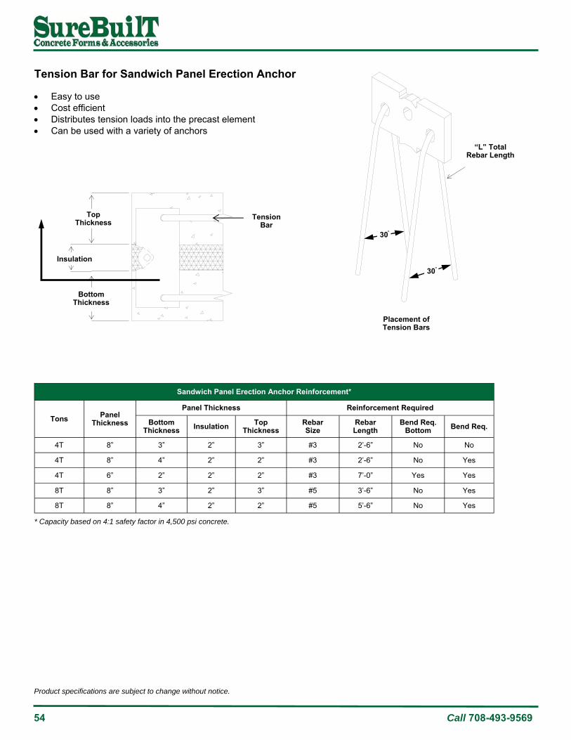
54 Call 708-493-9569
Product specifications are subject to change without notice.
Sandwich Panel Erection Anchor Reinforcement*
Tons Panel Thickness
Panel Thickness Reinforcement Required
Bottom Thickness Insulation Top
Thickness Rebar Size
Rebar Length
Bend Req. Bottom Bend Req.
4T 8” 3” 2” 3” #3 2’-6” No No
4T 8” 4” 2” 2” #3 2’-6” No Yes
4T 6” 2” 2” 2” #3 7’-0” Yes Yes
8T 8” 3” 2” 3” #5 3’-6” No Yes
8T 8” 4” 2” 2” #5 5’-6” No Yes
* Capacity based on 4:1 safety factor in 4,500 psi concrete.
Tension Bar for Sandwich Panel Erection Anchor Easy to use Cost efficient Distributes tension loads into the precast element Can be used with a variety of anchors
“L” Total Rebar Length
30
30
Placement of Tension Bars
Top Thickness
Insulation
Tension Bar
Bottom Thickness

Product specifications are subject to change without notice.
www.surebuilt-usa.com 55
Ring-Lift Lifter*
P/N Tons Load Range L B C D E
SBRL25T 2.5T 2-2.5T 10-15/16” 3-1/8” 3-1/16” 2-5/32” 3-3/4”
SBRL5T 5T 3-5T 12-31/32” 4-1/16” 3-15/16” 2-15/32” 4-19/32”
SBRL10T 10T 8-10T 17-3/8” 5-7/8” 5-1/4” 3-3/8” 6-11/32”
Ring-Lift Lifter Configured with a curved and interlocking clutch body Bolt and a high-strength bail Attaches quickly and lifts smoothly Ring clutch rotates and locks onto anchor head Standard bail rotates 180° for spall-free lifting Once in locking position, the Ring Clutch cannot be released Capacity rated in metric tons All Lifters marked with individual ID number (per OSHA)
Note: The bail, if positioned below the ring clutch, as shown, may lock itself in a position preventing free movement of the unit. In this position the bail might bend during lift. As the panel is lifted the clutch may bend. As the panel reaches a more vertical position the clutch will unlock itself resulting in an impact load.
Bail
Ring Clutch
C
D
E
L
B
* Capacity based on 5:1 safety factor.

56 Call 708-493-9569
Product specifications are subject to change without notice.
Ring-Lift Lifter Safety Inspection Guidelines 1. Inspection - Always inspect newly purchased/received Lifters. Always inspect Lifters before each application. Always
inspect the overall appearance for bends, kinks or other obvious damage. 2. Maintenance - Always inspect Lifters for bends, kinks, stress fractures, extreme wear or missing components after
each application. Always check the bail and handle for smooth rotation from the closed to open position. Chain links should be inspected for weld fractures and cables should be inspected for raveling/ruptures.
3. Damage - If the chain, cable, crimp, or lifter is damaged, then it must be immediately segregated/removed from service.
Any replacement part must be an equivalent (or larger) size and capacity. It should be replaced, tested and certified for load equal to 5 times the rated load.
Cable Lifter A length of chain or cable, attached to a standard Ring-Lift Lifter, simplifies difficult “rotate-to-vertical” situations. Once in the locking position and supporting the full load, the ring clutch cannot be inadvertently released. Both the Chain Lifter and Cable Lifter attach quickly and lift smoothly. The capacity of the Chain Lifter and Cable Lifter are designed to match the standard Ring-Lift Lifter rating, based on a 5:1 safety factor.
Ring-Lift Chain Lifter
Ring-Lift Cable Lifter
Ring-Lift Cable Lifter
P/N Clutch ID
Load Range
Total Length
Loop Length
SBRLCL25T 2.5T 2-2.5 Tons 24-1/2” 7”
SBRLCL5T 5T 4-5 Tons 26-1/2” 9”
SBRLCL10T 10T 8-10 Tons 37-1/2” 10-1/2”
* Capacity based on 5:1 safety factor.
Ring-Lift Chain Lifter
P/N Clutch ID
Load Range
Total Length
SBRLCHL25T 2.5T 2-2.5 Tons 14-1/2”
SBRLCHL5T 5T 4-5 Tons 18”
SBRLCHL10T 10T 8-10 Tons 29-1/2”
* Capacity based on 5:1 safety factor.

Product specifications are subject to change without notice.
www.surebuilt-usa.com 57
Recess Former - Reusable Urethane The Recess Former is used with any of the Ring-Lift anchors. It provides a fast and accurate void, with a consistent shape for smooth lifter attachment. The former is made with a durable urethane for easy stripping and reusability. A former is used when a hole in the formwork is undesirable. A mounting plate with four 3/16" diameter holes is used to fasten the anchor and former to the formwork by nailing, screwing, welding, or taping. The anchor and former are attached to the mounting plate by sliding the assembly over the two protruding pins on the plate.
Recess Former - Reusable Urethane
P/N Clutch ID
Load Range
Length (L)
Height (H)
WIidth (W)
Slot (A)
Spacing (B)
Hole Dia (C)
SBRLF1T 2.5T 1T 3-3/4” 1-15/16” 1-11/16” 3/16” 1-1/16” 0.406”
SBRLF2T 2.5T 2T-2.5T 3-3/4” 1-15/16” 1-11/16” 3/8” 1-1/16” 0.406”
SBRLF5T 5T 4T-5T 4-7/8” 2-1/4” 2-3/16” 5/8” 1-3/8” 0.406”
SBRLF10T 10T 8T-10T 6-1/2” 3-1/4” 3-1/2” 3/4” 1-15/16” 0.406”
Each former has two optional connections; one coil thread and one NC thread.
C
L W
B
A
H
Recess Former—Disposable Plastic
P/N Clutch ID
Load Range Color
SBRLDF2T 2.5T 2T-2.5T Green
SBRLDF4T 5T 4T-5T Orange
SBRLDF8T 10T 8T-10T Blue
Recess Former - Disposable Plastic The Recess Former is used with any of the Ring-Lift anchors. It provides a fast and accurate void, with a consistent shape for smooth lifter attachment. The former is made with a durable urethane for easy stripping and reusability

58 Call 708-493-9569
Product specifications are subject to change without notice.
Recess Former - Reusable Steel Use with Ring-Lift anchors Fast, accurate installation that forms consistent shape
around the anchor for better lifter attachment
Steel Wedge Only*
P/N Capacity Clutch ID
SBRLSFW2T 2T 2T
SBRLSFW4T 4T 5T
SBRLSFW8T 8T 10T
* Used to lock anchor in place.
L
T W
Steel Former
Foam Strip
Former Wedge
Recess Former - Reusable Steel*
P/N Capacity Clutch ID
SBRLSFH2T 2T 2T
SBRLSFH4T 4T 5T
SBRLSFH8T 8T 10T
* Complete Recess Former assembly.
Foam Strip Only
P/N Capacity Clutch ID L W T
SBRLFS2T 2T 2.5T 3” 2” 1/4”
SBRLFS4T 4T 5T 4” 2-1/2” 1/4”
SBRLFS8T 8T 10T 6” 3” 1/4”
* Used to lock Steel Wedge and anchor in place.

Product specifications are subject to change without notice.
www.surebuilt-usa.com 59
Mounting Bolt and Wing Nut
P/N Capacity Clutch ID L Coil
Thread
SBAFR3863812TC
1T 2.5T 6-3/8” 3/8“
2T 2.5T 6-3/8” 3/8“
4T 5T 6-3/8” 3/8“
SBAFR12638810TC 8T 10T 6-3/8” 1/2“
Mounting Bolt and Wing Nut Fastens Recess Former and Mounting Plate to form face.
Mounting Plate
P/N Capacity Clutch ID
Pin Diameter
SBRFFP12T 2T 2.5T 0.406”
SBRFFP34T 4T 5T 0.406”
SBRFFP68T 8T 10T 0.406”
Mounting Plate Two pins align the Recess Former Allows for easy stripping and multiple reuse
Mounting Plate on Recess Former
Form
Magnet Plates Reusable magnet for fastening transport anchors Magnet securely holds the lifting device Easily attached to any location along forming side rail Can be quickly removed, repositioned and reused
Magnet Plate
P/N Capacity
SBGB4049 2T-2.5T
SBGB4050 4T-5T
SBGB4051 8T-10T
Clutch ID
2.5T
5T
10T

60 Call 708-493-9569
Product specifications are subject to change without notice.

Product specifications are subject to change without notice.
www.surebuilt-usa.com 61
Edge-Lift Shear Bar 69
Lifter 70
Magnet Plate w/Recess Former 68
Mounting Bolt and Wing Nut w/Plate 67
Mounting Plate 68
Recess Former - Urethane 67
Uni-Eye Anchor 66
Uni-Lift Anchor 62
Uni-Lift Lifter 70
Uni-Lift System

62 Call 708-493-9569
Product specifications are subject to change without notice.
Uni-Lift Anchor The steel Uni-Lift Anchor remains ductile at low temperatures, making this anchor safe to use, even in freezing conditions. Each anchor is clearly marked for size and capacity. The large, specially-formed head, provides more contact area, yet still fits most existing and commonly used lifting hardware. Anchors are sampled, examined and tested for conformance to specifications. When using Uni-Lift Anchors in a face lift application, the capacity is determined by the full shear cone, the mechanical strength of the anchor, or in some cases, induced stresses.
Uni-Lift Anchor Thin-Wall Installation: Uni-Lift Anchors in thin wall applications must be properly positioned to avoid reduced load capacities. Anchors must be accurately positioned along the center line of the wall using spacers or rebar ties. The Safe Working Load (SWL) tension (see table) is based on two or more anchors in thin walls, where the spacing between anchors is less than 4 x L, and the minimum corner distance is 2 x L (L= anchor length). As with all Uni-Lift Anchor applications, the anchor must be located along the center line. The critical wall thickness will be 2 x L and the SWL must be reduced to that wall thickness. When multiple anchors are used in thin walls, caution must be exercised to prevent anchor shear cones from overlapping. Using a spacing of 4L between anchors will prevent overlap and maximize tensile capacity (see table). Proper positioning is extremely important. If the Uni-Lift Anchor foot is not in center, the SWL must be reduced to the critical wall thickness. Multiply the table values by the reduction factor to determine the allowable load.
D
D Wall
Thickness
Minimum Corner
Distance
Alternate Core Area Overlapping Area
Results in Working Load Reduction
L
Minimum Distance

Product specifications are subject to change without notice.
www.surebuilt-usa.com 63
Uni-Lift Anchor*
P/N Anchor Size
Former Size
Lifter Size T x Length Capacity
Safe Working Load (SWL) in Concrete**
@ 1,500 psi
@ 2,500 psi
@ 3,500 psi
@ 5,000 psi
SBULA382.5G
1T 1T 1-1.3T
1T x 2-1/2” 2,000 lbs 1,658 lbs 2,000 lbs 2,000 lbs 2,000 lbs
SBULA383.375G 1T x 3-3/8” 2,000 lbs 2,000 lbs 2,000 lbs 2,000 lbs 2,000 lbs
SBULA384.75G 1T x 4-3/4” 2,000 lbs 2,000 lbs 2,000 lbs 2,000 lbs 2,000 lbs
SBULA9162.187G
2T 1.5-2T 1.5-2.5T
2T x 2-3/16” 4,000 lbs 1,559 lbs 2,013 lbs 2,382 lbs 2,847 lbs
SBULA9162.5 2T x 2-1/2” 4,000 lbs 1,803 lbs 2,328 lbs 2,754 lbs 3,292 lbs
SBULA9162.75 2T x 2-3/4” 4,000 lbs 2,006 lbs 2,590 lbs 3,065 lbs 3,663 lbs
SBULA9163.375G 2T x 3-3/8” 4,000 lbs 2,546 lbs 3,286 lbs 3,888 lbs 4,000 lbs
SBULA9164.75G 2T x 4-3/4” 4,000 lbs 3,874 lbs 4,000 lbs 4,000 lbs 4,000 lbs
SBULA9165.5G 2T x 5-1/2” 4,000 lbs 4,000 lbs 4,000 lbs 4,000 lbs 4,000 lbs
SBULA9166.75G 2T x 6-3/4” 4,000 lbs 4,000 lbs 4,000 lbs 4,000 lbs 4,000 lbs
SBULA91611G 2T x 11” 4,000 lbs 4,000 lbs 4,000 lbs 4,000 lbs 4,000 lbs
SBULA343.75G
4T 4T 3-5T
4T x 3-3/4” 8,000 lbs 3,201 lbs 4,133 lbs 4,890 lbs 5,844 lbs
SBULA344.25G 4T x 4-1/4” 8,000 lbs 3,697 lbs 4,773 lbs 5,647 lbs 6,749 lbs
SBULA344.75G 4T x 4-3/4” 8,000 lbs 4,216 lbs 5,443 lbs 6,440 lbs 7,697 lbs
SBULA345.5G 4T x 5-1/2” 8,000 lbs 5,036 lbs 6,502 lbs 7,693 lbs 8,000 lbs
SBULA347.125G 4T x 7-1/8” 8,000 lbs 6,974 lbs 8,000 lbs 8,000 lbs 8,000 lbs
SBULA349.5G 4T x 9-1/2” 8,000 lbs 8,000 lbs 8,000 lbs 8,000 lbs 8,000 lbs
SBULA3413.375G 4T x 13-3/8” 8,000 lbs 8,000 lbs 8,000 lbs 8,000 lbs 8,000 lbs
SBULA1184.75G
8T 8T 6-10T
8T x 4-3/4” 16,000 lbs 4,478 lbs 5,781 lbs 6,840 lbs 8,175 lbs
SBULA1186.75G 8T x 6-3/4” 16,000 lbs 6,807 lbs 8,788 lbs 10,398 lbs 12,428 lbs
SBULA11810G 8T x 10” 16,000 lbs 11,233 lbs 14,501 lbs 16,000 lbs 16,000 lbs
SBULA11813.375G 8T x 13-3/8” 16,000 lbs 16,000 lbs 16,000 lbs 16,000 lbs 16,000 lbs
SBULA1129.875G
16T 20T 12-20T
16T x 10” 40,000 lbs 11,770 lbs 15,196 lbs 17,980 lbs 21,490 lbs
SBULA11215G 16T x 15-3/4” 40,000 lbs 22,657 lbs 29,250 lbs 34,609 lbs 40,000 lbs
SBULA11219.625G 16T x 20” 40,000 lbs 35,983 lbs 40,000 lbs 40,000 lbs 40,000 lbs
SBULA211G 25T 32T 25-32T
25T x 9-7/8” 50,000 lbs 12,286 lbs 15,861 lbs 18,767 lbs 22,431 lbs
SBULA220G 25T x 19-5/8” 50,000 lbs 32,691 lbs 42,204 lbs 49,936 lbs 50,000 lbs
SBULA118412G 8T x 4-1/2” 16,000 lbs 4,210 lbs 5,435 lbs 6,431 lbs 7,687 lbs
* Minimum distance between anchors is 4x the embedded depth. Minimum edge distance is 1.5x the embedded depth. ** Safe Working Load (SWL) based on 4:1 safety factor in 4,500 psi concrete.

64 Call 708-493-9569
Product specifications are subject to change without notice.
1 Ton Anchor*
Ton x Length
Critical Wall Thickness
Actual Edge Thickness
Actual Corner Distance**
6 in. 12 in. 18 in. 24 in. 30 in.
1 Ton x 4-3/4”
2-1/2” 1-1/4” 1,000 lbs 1,200 lbs 1,300 lbs 1,300 lbs 1,300 lbs
2-3/4” 1-3/8” 1,100 lbs 1,300 lbs 1,400 lbs 1,400 lbs 1,400 lbs
3” 1-1/2” 1,200 lbs 1,400 lbs 1,600 lbs 1,600 lbs 1,600 lbs
3-1/2” 1-3/4” 1,400 lbs 1,700 lbs 1,800 lbs 1,800 lbs 1,800 lbs
4” 2” 1,600 lbs 1,900 lbs 2,000 lbs 2,000 lbs 2,000 lbs
4-1/2” 2-1/4” 1,800 lbs 2,000 lbs 2,000 lbs 2,000 lbs 2,000 lbs
2 Ton Anchor*
Ton x Length
Critical Wall Thickness
Actual Edge Thickness
Actual Corner Distance**
6 in. 12 in. 18 in. 24 in. 30 in.
2 Ton x 6-3/4”
3” 1-1/2” 1,700 lbs 1,800 lbs 2,000 lbs 2,200 lbs 2,200 lbs
3-1/4” 1-5/8” 1,900 lbs 2,000 lbs 2,200 lbs 2,400 lbs 2,400 lbs
3-1/2” 1-3/4” 2,000 lbs 2,200 lbs 2,400 lbs 2,600 lbs 2,600 lbs
4” 2” 2,300 lbs 2,500 lbs 2,700 lbs 3,000 lbs 3,000 lbs
5” 2-1/2” 2,900 lbs 3,100 lbs 3,400 lbs 3,700 lbs 3,700 lbs
6” 3” 3,500 lbs 3,700 lbs 4,000 lbs 4,000 lbs 4,000 lbs
4 Ton Anchor*
Ton x Length
Critical Wall Thickness
Actual Edge Thickness
Actual Corner Distance**
10 in. 15 in. 20 in. 24 in. 30 in.
4 Ton x 9-1/2”
3-3/4” 1-7/8” 2,900 lbs 3,200 lbs 3,400 lbs 3,500 lbs 3,800 lbs
4” 2” 3,100 lbs 3,400 lbs 3,600 lbs 3,800 lbs 4,000 lbs
5” 2-1/2” 3,800 lbs 4,300 lbs 4,600 lbs 4,800 lbs 5,100 lbs
6” 3” 4,600 lbs 5,200 lbs 5,500 lbs 5,700 lbs 6,100 lbs
7” 3-1/2” 5,400 lbs 6,000 lbs 6,400 lbs 6,700 lbs 7,200 lbs
8” 4” 6,200 lbs 6,900 lbs 7,300 lbs 7,600 lbs 8,000 lbs
* Minimum distance between anchors is 4x the embedded depth. Minimum edge distance is 1.5x the embedded depth. ** Safe Working Load (SWL) based on 4:1 safety factor in 4,500 psi concrete.
* Minimum distance between anchors is 4x the embedded depth. Minimum edge distance is 1.5x the embedded depth. ** Safe Working Load (SWL) based on 4:1 safety factor in 4,500 psi concrete.
* Minimum distance between anchors is 4x the embedded depth. Minimum edge distance is 1.5x the embedded depth. ** Safe Working Load (SWL) based on 4:1 safety factor in 4,500 psi concrete.

Product specifications are subject to change without notice.
www.surebuilt-usa.com 65
8 Ton Anchor*
Ton x Length
Critical Wall Thickness
Actual Edge Thickness
Actual Corner Distance**
10 in. 15 in. 20 in. 24 in. 30 in.
8 Ton x 6-3/4”
4-3/4” 2-3/8” 3,000 lbs 3,300 lbs 3,600 lbs 3,700 lbs 3,700 lbs
5” 2-1/2” 3,200 lbs 3,500 lbs 3,800 lbs 3,900 lbs 3,900 lbs
6” 3” 3,800 lbs 4,200 lbs 4,600 lbs 4,700 lbs 4,700 lbs
7” 3-1/2” 4,500 lbs 4,900 lbs 5,400 lbs 5,500 lbs 5,500 lbs
8” 4” 5,100 lbs 5,600 lbs 6,100 lbs 6,200 lbs 6,500 lbs
10” 5” 6,300 lbs 6,900 lbs 7,500 lbs 7,700 lbs 7,700 lbs
8 Ton Anchor*
Ton x Length
Critical Wall Thickness
Actual Edge Thickness
Actual Corner Distance**
12 in. 18 in. 24 in. 36 in. 45 in.
8 Ton x 13-3/8”
5” 2-1/2” 4,500 lbs 5,500 lbs 5,900 lbs 6,500 lbs 7,000 lbs
6” 3” 5,500 lbs 6,500 lbs 7,100 lbs 7,800 lbs 8,000 lbs
7” 3-1/2” 6,500 lbs 7,600 lbs 8,300 lbs 9,100 lbs 10,000 lbs
8” 4” 7,300 lbs 8,700 lbs 9,500 lbs 10,800 lbs 11,500 lbs
10” 5” 9,100 lbs 11,000 lbs 12,000 lbs 13,500 lbs 14,000 lbs
12” 6” 11,000 lbs 13,000 lbs 14,200 lbs 16,000 lbs 16,000 lbs
10 Ton Anchor*
Ton x Length
Critical Wall Thickness
Actual Edge Thickness
Actual Corner Distance**
12 in. 18 in. 24 in. 36 in. 45 in.
16 Ton x 19-5/8”
6-1/2” 3-1/4” 7,000 lbs 9,000 lbs 10,500 lbs 11,500 lbs 12,200 lbs
7” 3-1/2” 8,000 lbs 10,000 lbs 11,500 lbs 12,500 lbs 13,200 lbs
8” 4” 9,200 lbs 11,200 lbs 13,000 lbs 14,400 lbs 15,100 lbs
10” 5” 11,500 lbs 14,300 lbs 16,000 lbs 18,000 lbs 19,000 lbs
12” 6” 14,000 lbs 17,300 lbs 20,000 lbs 21,500 lbs 22,800 lbs
14” 7” 16,200 lbs 20,200 lbs 23,000 lbs 25,000 lbs 26,600 lbs
* Minimum distance between anchors is 4x the embedded depth. Minimum edge distance is 1.5x the embedded depth. ** Safe Working Load (SWL) based on 4:1 safety factor in 4,500 psi concrete.
* Minimum distance between anchors is 4x the embedded depth. Minimum edge distance is 1.5x the embedded depth. ** Safe Working Load (SWL) based on 4:1 safety factor in 4,500 psi concrete.
* Minimum distance between anchors is 4x the embedded depth. Minimum edge distance is 1.5x the embedded depth. ** Safe Working Load (SWL) based on 4:1 safety factor in 4,500 psi concrete.

66 Call 708-493-9569
Product specifications are subject to change without notice.
Uni-Eye Anchor with Rebar The Uni-Eye Anchor with Rebar is used in conjunction with the segment reinforcing. A bar is installed through the anchor to develop deep tensile action. This combination allows anchors to develop greater working loads when used in thin concrete wall sections.
Uni-Eye Anchor with Rebar
P/N Load Rating
Length (L)
Min Panel Thickness
Min Corner Distance
Min Anchor Spacing*
Tension w/ Rebar**
SBULEA1TG 1T 2-5/8” 3” 8” 16” 2,000 lbs
SBULEA2TG 2T 3-1/2” 3” 4” 8” 4,000 lbs
SBULEA4TG 4T 4-3/4” 4” 6” 12” 8,000 lbs
SBULEA8T434G 8T 4-3/4” 5” 8” 16” 16,000 lbs
SBULEA8TG 8T 7-1/8” 5” 8” 16” 16,000 lbs
SBULEA16TG 16T 9-7/8” 6-1/2” 10” 18” 32,000 lbs
SBULEA25TG 25T 12” 7-7/8” 12” 24” 50,000 lbs
Tension Bar
Load Rating
Rebar Grade 60
Overall Length
Spread (L)
Bending Radius (R)
1T #3 36” 12” 3/4”
2T #3 24” 6” 1-1/4”
4T #5 24” 7” 2”
8T #6 48” 9” 2-1/2”
16T #8 86” 12” 3”
25T #10 100” 16” 4”
L
R
* Anchors must be centered when installed. Deviation will result in a reduced Safe Working Load.. ** Safe Working Load (SWL) based on 4:1 safety factor with Tension Bar in 2,000 psi concrete minimum.
L
Min Anchor Spacing
L
Min Corner Distance
Wall Thickness
Center Line of Walls and Anchors

Product specifications are subject to change without notice.
www.surebuilt-usa.com 67
Recess Former This Recess Former has a threaded hole plate located in the top for installation of a threaded stud that can be removed before form stripping. After removing the threaded stud, the concrete element is removed from the forms with the stripping anchors. The reusable urethane Recess Former can then be removed to expose the anchor.
Recess Former
P/N Anchor Size
Shank (D)
Head (H)
Foot (F)
Cover (C)
Width (A)
Height (B)
SBRRF1T 1T 3/8” 11/16” 1 3/8” 2-3/8” 1-3/16”
SBRRF2T 2T 9/16” 31/32” 1-3/8 7/16” 3” 1-9/16”
SBRRF4T 4T 3/4” 1-11/32” 2 9/16” 3-3/4” 1-7/8”
SBRRF8T 8T 1-1/8” 1-7/8” 2-3/4 9/16” 4-3/4” 2-5/16”
SBRRF16T 16T 1-1/2” 2-3/4” 3-7/8 9/16” 6-3/8” 3-1/8”
SBRRF25T 25T 2” 3-15/32” 5-5/16 9/16” 8” 4”
A
B
Recess Former with Mounting Bolt and Wing Nut Rubber recess former with wing nut has a permanent threaded stud with one wing nut to tighten securely against form. The threaded stud is not removable and the form must be stripped before the anchor can be exposed for lifting
W
H
D
L
Mounting Bolt and Wing Nut with Plate Supplied as part of rubber former with permanent threaded stud. Available as a replacement part. Made with NC threads and welded to plate at bottom of stud.
Mounting Bolt and Wing Nut with Plate
P/N Anchor Size
Clutch ID
Length (W)
Bolt (D)
Width (W)
Height (H)
SBFP1TWN 1T 1.3T 6-3/8” 5/16-18 NC 1.187” 0.500”
SBFP2TWN 2T 2.5T 6-3/8” 5/16-18 NC 1.500” 0.781”
SBFP4TWN 4T 5T 6-3/8” 5/16-18 NC 1.875” 1.000”
SBFP8TWN 8T 10T 6-3/8” 3/8-16 NC 2.343” 1.187”
SBFP16TWN 16T 15-20T 6-3/8” 1/2-13 NC 3.031” 1.562”
SBFP25TWN 25T 32T 6-3/8” 5/8-11 NC 3.031” 1.562”
H F
D
C
Side View

68 Call 708-493-9569
Product specifications are subject to change without notice.
Mounting Plate Only
P/N Anchor Size
Clutch ID
Bolt Dia
SBUFFP1T 1T 1.3T 5/16-18 NC
SBUFFP2T 2T 2.5T 5/16-18 NC
SBUFFP4T 4T 5T 5/16-18 NC
SBUFFP8T 8T 10T 3/8-16 NC
SBUFFP16T 16T 15-20T 1/2-13 NC
SBUFFP25T 25T 32T 5/8-11 NC
Magnet Plate and Former
P/N Anchor Size
SBGB5011 2T
SBGB5012 4T
SBGB5014 8T
Magnet Plate and Recess Former Reusable magnet for fastening anchors Magnet securely holds the lifting device Easily attached to any location along steel forming side rail Can be quickly removed, repositioned and reused
Mounting Plate The Mounting Plate is used to accurately position the Recess Former and anchor in the precast form.

Product specifications are subject to change without notice.
www.surebuilt-usa.com 69
Edge-Lift Shear Bar When lifting a panel with an anchor in the panel edge from horizontal to vertical, Edge-Lift Shear Bars must be used. Without shear bars the load will likely bend the anchor head, allowing the Lifter to apply the load to the concrete above the anchor, which is very weak. The shear bars transfer a portion of the load back into the anchor and lower concrete area.
L L W
H
3/4Edge-Lift Shear Bar
P/N Anchor Size
Length (L)
Width (W)
Height (H)
SBUSB1T 1T 8” 2-3/8” 3-11/16”
SBUSB2T 2T 8” 3” 4”
SBUSB4T 4T 12” 3-3/4” 5-5/8”
SBUSB8T 8T 14” 4-3/4” 7-3/8”
Edge-Lift Shear Bar Load
Anchor Size
Min. Anchor Length
Min. Wall Thickness
Top Edge Distance
Min Corner Distance Shear*
2T
6-3/4” 4” 2-1/2” 18” 3,000 lbs
6-3/4” 5” 3” 24” 3,200 lbs
6-3/4” 6” 3-1/2” 24” 3,500 lbs
4T 9-1/2” 6” 3-1/2” 24” 3,500 lbs
9-1/2” 7” 4” 24” 4,000 lbs
8T 13-3/8” 7” 4” 24” 4,500 lbs
13-3/8” 8” 4-1/2” 24” 5,000 lbs
* Safe Working Load (SWL) based on 4:1 safety factor in 4,500 psi concrete.

70 Call 708-493-9569
Product specifications are subject to change without notice.
Uni-Lift Lifter The Uni-Lift Lifter is specially-designed with a T-shaped slot that captures the anchor head. The bail is a solid steel plate with a large hole to attach a cable clevis. The bail rotates from front to back in the lifting body. This action is an advantage over other systems as rigging does not need to be reversed when rotating a panel up and down. All Uni-Lift Lifters are proof loaded to 2.5x the Safe Working Load (SWL) and marked with an individual ID number in compliance with OSHA regulations. SureBuilt recommends regular inspection to identify excessive wear, damage, loading, misuse, modification or other factors which may affect lifting performance. Under no circumstances should user modify, heat, weld or grind any part of the lifting hardware.
Uni-Lift Lifter
P/N Lifter ID A B C D E F G Capacity*
SBUL1.3T 1-1.3 T 1.87” 2.95” 2.80” 2.20” 2.17” 1.30” 6.48” 2,850 lbs
SBUL2.5T 2-2.5 T 2.52” 3.86” 3.35” 2.68” 2.76” 1.65” 8.09” 5,500 lbs
SBUL5T 3.0-5.0 T 2.76” 4.65” 3.45” 3.46” 3.39” 2.24” 9.33” 11,000 lbs
SBUL10T 6.0-10.0 T 3.74” 10.24” 4.76” 4.41” 4.61” 2.87” 13.72” 22,000 lbs
SBUL20T 12.0-20.0 T 4.65” 7.32” 5.91” 5.98” 6.10” 4.33” 17.36” 44,000 lbs
SBUL32T 25.0-32.0 T 6.89” 10.59” 7.44” 7.68” 8.43” 6.02” 22.99” 70,000 lbs
A
C
D E
F
G
B
* Safe Working Load (SWL) based on 5:1 safety factor in 3,500 psi concrete.

Product specifications are subject to change without notice.
www.surebuilt-usa.com 71
Anchor 500 77
Cable Loop Anchors 78
Magnet Plate 76
Mounting Plate 76
Recess Former - Urethane 74
Recess Former - Anchor 500 77
Utility Anchor 74
Utility Anchor w/Snap Wires 75
Easy-Lift System

72 Call 708-493-9569
Product specifications are subject to change without notice.
Easy-Lift System Economical alternative for stripping, handling, and setting panels Versatile system - applicable to any precast element, can be used as pulling iron or lifting and pulling iron. High strength - Up to 6 Tons (12,000 lb) Tension SWL with an approximate 4:1 safety factor. Easy to install and use. Utilizes reusable rubber recess former - one size plug fits all anchor sizes. Used with a standard hook or clevis - no special lifting hardware required. Eliminates “through holes” in the precast element. The Easy Lift Utility Anchor Lifting System is designed to economically simplify the lifting and handling of precast concrete elements. Its economics, ease of use and versatility will be a welcome addition to your precast operations. The Easy Lift can be utilized for removing the precast elements from their forms, handling the elements in the precast yard, loading for shipment and unloading and placement at the job site - all without any special lifting equipment or hardware. Use a standard hook or clevis to connect to the Utility Anchor for a safe lift. An added benefit is a design feature that enables the unit to be used effectively as a pulling iron.
Barriers
Pipe
Boxes
Slabs
EASY-LIFT 450
EASY-LIFT 670
Mounting Bolt and Wing Nut
Reusable Mounting
Plate
Easy-Lift Reusable Former
Easy-Lift Utility Anchor
Specially-designed large foot for bigger shear cone.
Caution: It is recommended when installing anchors to align recess formers with intended loading direction of cables (see drawing).

Product specifications are subject to change without notice.
www.surebuilt-usa.com 73
In-Form Setting 1. Assemble recess former and Easy Lift
anchor. 2. Affix reusable mounting plate (nail, weld or
double-sided tape) to form. 3. Push former onto the holding plate firmly
against the panel.
Easy-Lift Anchor Placement Placement of the Easy Lift anchor is dependent on the structural shape of the precast unit and/or the precast manu-facturer’s preference. The anchors are not designed for thin edge installations. Always maintain minimum edge distances and adjust anchor capacities if concrete strengths other than those noted in the capacity chart are encountered.
Wet-Setting 1. Assemble Easy Lift anchor with steel plate
and nut and bolt assembly OR assemble Easy Lift anchor with wet-set plate inserted into holes.
2. Use duct tape to seal cavities in the setting plug.
3. Work the assembly down into the wet concrete until the top surface of the plug is flush with the surface of the concrete or use floating plate.
Through-Form Setting 1. Assemble recess former and Easy Lift
anchor. 2. Insert holding coil rod through panel and line
up former. 3. Finger tighten the holding rod and lock in
place with the corresponding wing nut.
Rubber
Panel
Reusable Mounting Plate
Anchor
Steel Plate
Anchor
Wet-Set Plate
Anchor
Anchor
Rubber former
Panel
1/2” Coil Rod

74 Call 708-493-9569
Product specifications are subject to change without notice.
E
D
B
A
Cover 3/4”
Easy-Lift Recess Former
P/N C D E
SBUAF450 8” 3” 3-1/4”
SBELF670L 10” 3” 3-1/4”
SBUELF670 10” 3” 3-1/4”
Anchor Dia.
.450
.670
.670
Color
Orange
Green
Black
Easy-Lift Utility Anchor
P/N Thickness A* B F G
SBUA450318 4” 3-1/8” 5.281 0.450 1.375
SBUA450334 4-1/2” 3-3/4” 6.000 0.450 1.375
SBUA450434 5-1/2” 4-3/4” 7.122 0.450 1.375
SBUA450634 8” 6-3/4” 9.375 0.450 1.375
SBUEL4 4” 3-1/8” 5.300 0.670 1.340
SBUEL412 4-1/2” 3-3/4” 6.800 0.670 1.340
SBUEL512 5-1/2” 4-3/4” 7.400 0.670 1.340
SBUEL8 8” 6-3/4” 10.000 0.670 1.340
Shear**
1,800 lbs
6,500 lbs
8,000 lbs
9,000 lbs
2,500 lbs
7,500 lbs
10,000 lbs
13,500 lbs
Tension**
1,200 lbs
3,000 lbs
4,000 lbs
5,000 lbs
2,000 lbs
4,800 lbs
7,200 lbs
12,000 lbs
Note: When the Easy-Lift Utility Anchor is used as a pulling iron, the SWL can be increased by 33%.
Shear Load
Tension Load
Easy-Lift Utility Anchor The Easy-Lift Utility Anchor is an efficient and economical way to handle precast segments. The 0.450 and 0.670 legs, in combination with the slab thickness, provide the necessary capacity for typical concrete shapes. The anchor is always used in combination with a Recess Former. The former creates a void in the concrete for subsequent hooking and handling.
* Minimum edge distance in any direction is 2x anchor height. ** Safe Working Load (SWL) based on 4:1 safety factor in 4,000 psi concrete
Easy-Lift Recess Former - Urethane The Recess Former is used with any of the Ring-Lift anchors. It provides a fast and accurate void, with a consistent shape for smooth lifter attachment. The former is made with a durable ure-thane for easy stripping and reusability. A former is used when a hole in the formwork is undesirable. A mounting plate with four 3/16" diameter holes is used to fasten the anchor and former to the formwork by nailing, screwing, welding, or taping. The anchor and former are attached to the mounting plate by sliding the assembly over the two protruding pins on the plate.
C
F
G

Product specifications are subject to change without notice.
www.surebuilt-usa.com 75
Easy-Lift Utility Anchor with Snap Wires Easily attaches to wire mesh for side or vertical mounting Ideal for handling concrete pipes Available in .670 or .450 wire diameter Use with Easy Lift 670 green or 450 orange rubber former
Attaches to wire mesh
Cross View in Concrete
Form Former
Cross Section View
Easy-Lift Utility Anchor with Snap Wire
P/N Thickness A* B F G
SBUA450318SW 4” 3-1/8” 5.281 0.450 1.375
SBUA450334SW 4-1/2” 3-3/4” 6.000 0.450 1.375
SBUA450434SW 5-1/2” 4-3/4” 7.122 0.450 1.375
SBUA450634SW 8” 6-3/4” 9.375 0.450 1.375
SBUEL4SW 4” 3-1/8” 5.300 0.670 1.340
SBUEL412SW 4-1/2” 3-3/4” 6.800 0.670 1.340
SBUEL512SW 5-1/2” 4-3/4” 7.400 0.670 1.340
SBUEL8SW 8” 6-3/4” 10.000 0.670 1.340
Shear**
1,800 lbs
6,500 lbs
8,000 lbs
9,000 lbs
2,500 lbs
7,500 lbs
10,000 lbs
13,500 lbs
Tension**
1,200 lbs
3,000 lbs
4,000 lbs
5,000 lbs
2,000 lbs
4,800 lbs
7,200 lbs
12,000 lbs
* Minimum edge distance in any direction is 2x anchor height. ** Safe Working Load (SWL) based on 4:1 safety factor in 4,000 psi concrete
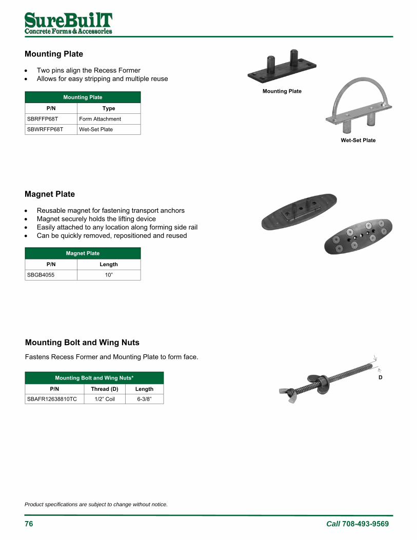
76 Call 708-493-9569
Product specifications are subject to change without notice.
Mounting Bolt and Wing Nuts*
P/N Thread (D) Length
SBAFR12638810TC 1/2” Coil 6-3/8”
D
Mounting Bolt and Wing Nuts Fastens Recess Former and Mounting Plate to form face.
Mounting Plate Two pins align the Recess Former Allows for easy stripping and multiple reuse
Magnet Plate Reusable magnet for fastening transport anchors Magnet securely holds the lifting device Easily attached to any location along forming side rail Can be quickly removed, repositioned and reused
P/N Type
SBRFFP68T Form Attachment
SBWRFFP68T Wet-Set Plate
Mounting Plate
Magnet Plate
P/N Length
SBGB4055 10”
Wet-Set Plate
Mounting Plate
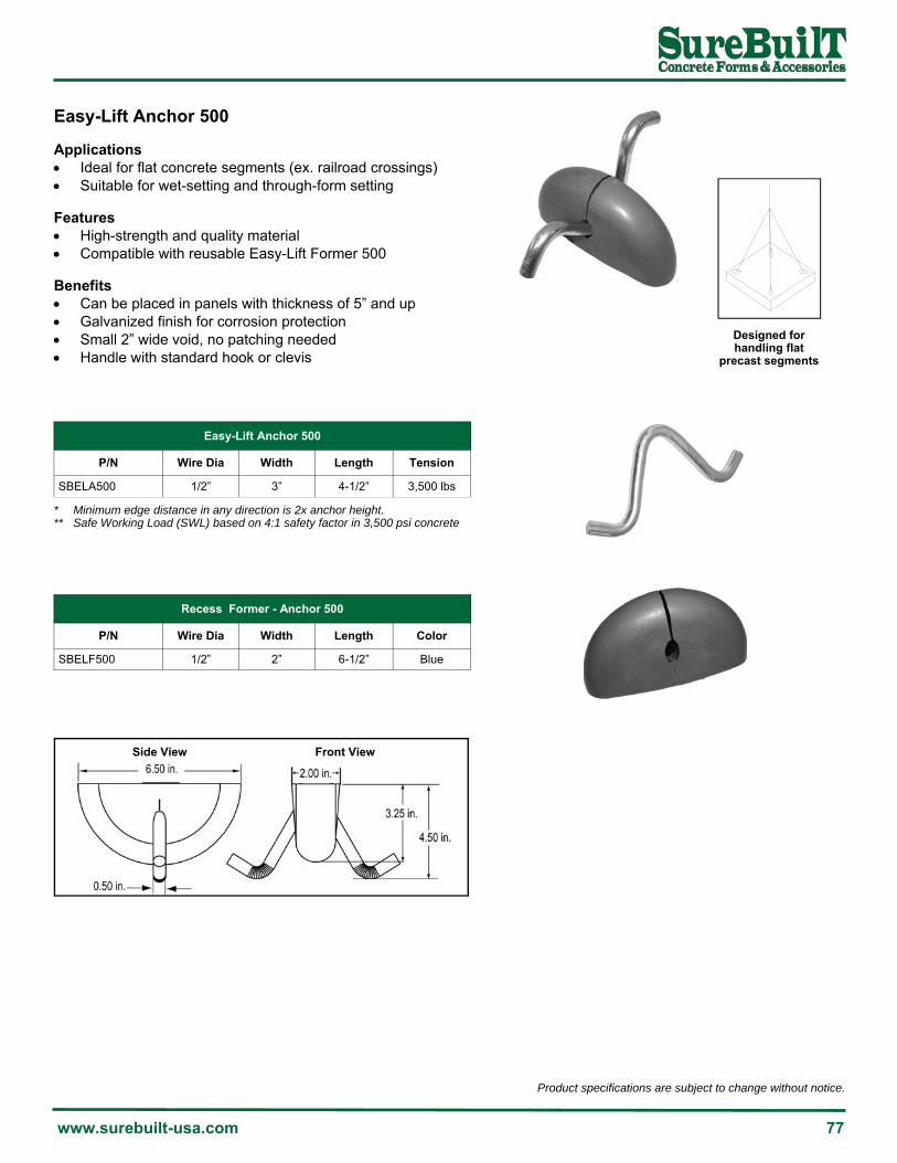
Product specifications are subject to change without notice.
www.surebuilt-usa.com 77
Easy-Lift Anchor 500 Applications Ideal for flat concrete segments (ex. railroad crossings) Suitable for wet-setting and through-form setting Features High-strength and quality material Compatible with reusable Easy-Lift Former 500 Benefits Can be placed in panels with thickness of 5” and up Galvanized finish for corrosion protection Small 2” wide void, no patching needed Handle with standard hook or clevis
Designed for handling flat
precast segments
Side View Front View
Easy-Lift Anchor 500
P/N Wire Dia Width Length
SBELA500 1/2” 3” 4-1/2”
Tension
3,500 lbs
* Minimum edge distance in any direction is 2x anchor height. ** Safe Working Load (SWL) based on 4:1 safety factor in 3,500 psi concrete
Recess Former - Anchor 500
P/N Wire Dia Width Length
SBELF500 1/2” 2” 6-1/2”
Color
Blue

78 Call 708-493-9569
Product specifications are subject to change without notice.
Cable Loop Anchor The Cable Loop Anchor is an efficient and economical method for handling precast concrete, including beams, ballast and walls. Ideal for precast concrete units with unexposed sides after lifting Capacities from 0.8 tons to 25 tons Protruding loops can be cut off or covered in concrete
Cable Loop Anchor*
P/N Load Length B H D Tag Color Tension**
SB8WRA 0.8 Tons 21” 3-3/4” 8” 0.236” White 1,600 lbs
SB12WRA 1.2 Tons 24” 4” 9” 0.276” Red 2,400 lbs
SB16WRA 1.6 Tons 26” 5” 10” 0.315” Purple 3,200 lbs
SB20WRA 2.0 Tons 31” 5-1/4” 12” 0.354” Green 4,000 lbs
SB25WRA 2.5 Tons 32-1/2” 5-1/2” 13” 0.394” Dark grey 5,000 lbs
SB40WRA 3.8 Tons 37” 6-1/2” 14-1/2” 0.472” Yellow 7,600 lbs
SB50WRA 5.0 Tons 38” 7” 15” 0.551” Dark blue 10,000 lbs
SB63WRA 6.3 Tons 44” 9-1/4” 16-1/2” 0.630” Light blue 12,600 lbs
SB80WRA 8.0 Tons 51” 9-1/4” 19” 0.709” Light grey 16,000 lbs
SB99WRA 9.9 Tons 55-1/2” 10-1/4” 21” 0.787” Pink 19,800 lbs
SB120WRA 12.0 Tons 60” 11” 23” 0.866” Black 24,000 lbs
SB160WRA 16.0 Tons 71” 12-3/4” 26” 1.024” Brown 32,000 lbs
SB180WRA 18.0 Tons 79” 15” 29-1/2” 1.102” Orange 36,000 lbs
SB250WRA 25.0 Tons 89’” 15-3/4” 33-1/2” 1.260” Tan 50,000 lbs
* Recommended embedment is 2/3H to develop full working load. ** Safe Working Load (SWL) based on 4:1 safety factor in 4,000 psi concrete
B
H
D

Product specifications are subject to change without notice.
www.surebuilt-usa.com 79
Accessories
Anchor Rail 80
Bearing Pads 81
C-Connector 89
Chord Connector 82
Column Base Connector 83
Edge Connector 86
Edge Protector - Plastic 91
FRP Truss 88
M-Connector 89
Plastic Chairs 90
Shims - Plastic 91
Slab Bolster - Plastic 91
Slant Anchor 85
Wall Base Connector 84
Wire Truss 87
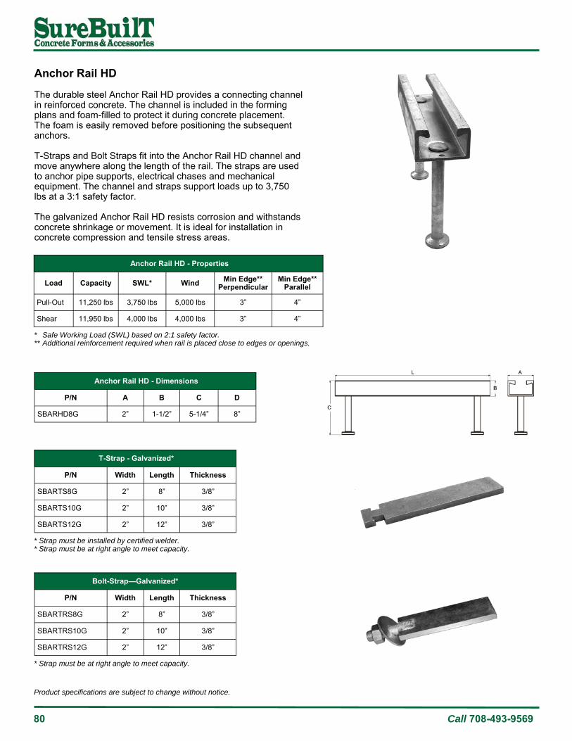
80 Call 708-493-9569
Product specifications are subject to change without notice.
Anchor Rail HD The durable steel Anchor Rail HD provides a connecting channel in reinforced concrete. The channel is included in the forming plans and foam-filled to protect it during concrete placement. The foam is easily removed before positioning the subsequent anchors. T-Straps and Bolt Straps fit into the Anchor Rail HD channel and move anywhere along the length of the rail. The straps are used to anchor pipe supports, electrical chases and mechanical equipment. The channel and straps support loads up to 3,750 lbs at a 3:1 safety factor. The galvanized Anchor Rail HD resists corrosion and withstands concrete shrinkage or movement. It is ideal for installation in concrete compression and tensile stress areas.
Anchor Rail HD - Dimensions
P/N A B C D
SBARHD8G 2” 1-1/2” 5-1/4” 8”
T-Strap - Galvanized*
P/N Width Length Thickness
SBARTS8G 2” 8” 3/8”
SBARTS10G 2” 10” 3/8”
SBARTS12G 2” 12” 3/8”
* Strap must be installed by certified welder. * Strap must be at right angle to meet capacity.
Bolt-Strap—Galvanized*
P/N Width Length Thickness
SBARTRS8G 2” 8” 3/8”
SBARTRS10G 2” 10” 3/8”
SBARTRS12G 2” 12” 3/8”
* Strap must be at right angle to meet capacity.
Anchor Rail HD - Properties
Load Capacity SWL* Wind Min Edge** Perpendicular
Shear 11,950 lbs 4,000 lbs 4,000 lbs 3”
Pull-Out 11,250 lbs 3,750 lbs 5,000 lbs 3”
Min Edge** Parallel
4”
4”
* Safe Working Load (SWL) based on 2:1 safety factor. ** Additional reinforcement required when rail is placed close to edges or openings.

Product specifications are subject to change without notice.
www.surebuilt-usa.com 81
Bearing Pad A unique combination of compressive strength, tear resistance, and cold weather flexibility makes this an exceptional material for concrete-to-concrete and concrete-to-steel bearing pads. Typical applications for the Bearing Seat include precast concrete seats, shims, bumpers and isolators. The material is available in lengths up to 48”, widths up to 48”, and thicknesses from 1/4” to 1”, to meet project specifications.
Bearing Pad Properties
Property Test Method Value
Hardness (Shore A) ASTM D-2240 80 ±5
Tensile Strength ASTM D-2240-412 Die C 1,000 psi (±10%)
Compression - Maximum Strength 10,000 psi
Compression - Initial Cracking 40%
Tear Strength ASTM D-624 Die B 400 psi Minimum (±10%)
Heat Aging - Change in Tensile ASTM D-573 25% Maximum
Heat Aging - Change in Elongation ASTM D-573 25% Maximum
Heat Aging - Change in Hardness ASTM D-471 10 Points Maximum
Oil Swell (increase in volume) ASTM D-471 120% Maximum

82 Call 708-493-9569
Product specifications are subject to change without notice.
Chord Connector and Former (sold separately)
P/N Description Rebar Coupler Capacity*
SBCC12212 Chord Connector 1/2”x2”x12” #6 x30” 3/4” NC x2-1/2” 47,500 lbs
SBCC12212SS Chord Connector 1/2”x2”x12” SS #6 x30” 3/4” NC x2-1/2” 47,500 lbs
SBCC12212F Chord Connector Former - - - - - -
* Capacity based on 5,000 psi concrete. Placement location must be approve by Engineer of Record (EOR).
Chord Connector The Chord Connector assembly is tied to rebar at a pre-engineered location, positioning the steel plate at the edge of a precast element for later welding. The plates of adjoining precast elements are welded together to reinforce the structure. The minimum weld length is 7” using a 3/8”x8” weld slug, in accordance with American Welding Society (AWS) standards. The Chord Connector is suitable for end-to-end and edge-to-edge welding in single tees, double tees and other precast elements.
Reusable rubber former to accurately position Chord Connector in precast form.
Chord Connector with stud.
Chord Connector without stud.

Product specifications are subject to change without notice.
www.surebuilt-usa.com 83
Column Base Connector The pre-engineered assembly provides a moment connection at column-to-base and column-to-column locations. This bolted connection eliminates the need for temporary bracing and saves time. The Column Base Connector is designed for common anchor bolt sizes. An integrated box-out provides access at each bolt location. The plate and rebar are matched to load specifications. Each Column Base Connector includes a steel plate (Grade 50) and rebar (A706) welded in accordance with American Welding Society (AWS) standards. An optional galvanized finish is also available. Once the columns have been positioned and bolted, the column base must be grouted to provide bearing for the engineered load.
Column Base Connector
SBCBC34 SBCBC1 SBCBC114 SBCBC112
Base Plate 3-1/2”x3-1/2” 4”x4” 5”x5” 7”x7”
Plate Thickness 3/4” 1-1/4” 1-3/4” 2”
Hole Size 1-1/8” 1-3/8” 1-3/4” 2:
Rebar size/length #5 x33” #6 x42” #8 x52” #9 x70”
Shear (lbs) 9,500 17,000 27,000 47,000
Tension (lbs) * 19,000 34,000 54,000 95,000
Anchor bolt size 3/4”x16” 1”x17” 1-1/4”x20” 1-1/2”x30”
Anchor bolt F1554 Grade 55 Grade 55 Grade 55 Grade 90
* Tension based on 6,000 psi concrete.
Site construction moves quickly when columns are positioned and bolted into place. Column base should be grouted as soon as possible after installation.

84 Call 708-493-9569
Product specifications are subject to change without notice.
Wall Base Connector The pre-engineered assembly provides a moment connection at wall-to-base and wall-to-wall locations. This bolted connection eliminates the need for temporary bracing and panel welding, saving time. The Wall Base Connector is designed for common anchor bolt sizes. An integrated box-out provides access at each bolt location. The plate and rebar are matched to load specifications. Each Wall Base Connector includes a steel plate (Grade 50) and rebar (A706) welded in accordance with American Welding Society (AWS) standards. An optional galvanized finish is also available. Once the wall panels have been positioned and bolted, the base must be grouted to provide bearing for the engineered load.
Wall Base Connector
SBCBC34 SBCBC1 SBCBC114 SBCBC112
Base Plate 3-1/2”x3-1/2” 4”x4” 5”x5” 7”x7”
Plate Thickness 3/4” 1-1/4” 1-3/4” 2”
Hole Size 1-1/8” 1-3/8” 1-3/4” 2:
Rebar size/length #5 x33” #6 x42” #8 x52” #9 x70”
Shear (lbs) 9,500 17,000 27,000 47,000
Tension (lbs) * 19,000 34,000 54,000 95,000
Anchor bolt size 3/4”x16” 1”x17” 1-1/4”x20” 1-1/2”x30”
Anchor bolt F1554 Grade 55 Grade 55 Grade 55 Grade 90
* Tension based on 6,000 psi concrete.

Product specifications are subject to change without notice.
www.surebuilt-usa.com 85
Slant Anchor The Slant Anchor assembly connects tilt-up or precast panels to the foundation. The assembly includes a load-rated Slant An-chor, foam Void Former, high-strength Ductile Bar and pre-packaged Flowable Grout. The Slant Anchor is integral to panel design and planning. The anchors are positioned and reinforced in each panel during con-crete forming operations. The foam Void Former covers the con-nection sleeve during concrete placement. Once a completed concrete panel is ready for installation, the foam Void Former is removed. The connection sleeve is now visible and accessible for subsequent anchoring. Each concrete panel is positioned on the foundation and braced. A hole is drilled into the foundation footing using the connection sleeve as a guide. The hole is then partially grouted, the Ductile Bar inserted, and the remaining grout used to fill the sleeve. This grouted connec-tion anchors the panel without welding or bolting. The working load of the Slant Anchor is 9,000 lbs for uplift, hori-zontal and shear forces, at a 3:1 safety factor. This meets the tensile strength requirements of ACI-318-14 section 16.2.4.3 (b).
Slant Anchor Assembly*
P/N Type Panel Width Finish
SBTSAC Standard 7” minimum Painted
SBPSAC Slim 5-1/2” to 7” Painted
* Assembly includes anchor, void former, ductile bar and grout.
Standard type
Slim type

86 Call 708-493-9569
Product specifications are subject to change without notice.
Edge Connector The Edge Connector is a rebar-winged embed designed for precast or tilt-up concrete applications. The rebar “wing” is tied into the panel reinforcing steel, with the “flat” positioned at the panel edge for later welding. The rectangular “flat” on the Edge Connector provides for a thicker, more reliable, field welding surface between adjoining precast panels. The rectangular shape exhibits greater weld strength, with less variability, compared to typical round slugs. The Edge Connector exhibits excellent performance in Horizontal Shear, Tension and Vertical Shear, making it suitable for precast or tilt-up concrete applications, including parking garage floors, roof slabs, bridge decks and industrial walls.
Edge Connector Former
P/N Description
SBECF4 Edge Connector Former #4 1” (Red)
SBECF5 Edge Connector Former #5 1-1/2” (Blue)
Plastic former accurately positions Edge Connector in form.
Edge Connectors are used to weld adjacent precast segments.
Edge Connector
P/N Description Type Horizontal Shear* Tension* Vertical
Shear*
SBEC4R Edge Connector #4 w/1” Flange A706 16,520 lbs 7,210 lbs 3,020 lbs
SBEC4RSS Edge Connector #4 w/1” Flange 2304SS 18,960 lbs 9,340 lbs 3,020 lbs
SBEC5R Edge Connector #5 w/1” Flange A706 27,680 lbs 11,740 lbs 6,390 lbs
SBEC5RSS Edge Connector #5 w/1” Flange 2304SS 32,670 lbs 12,590 lbs 6,390 lbs
* Ultimate load capacities.

Product specifications are subject to change without notice.
www.surebuilt-usa.com 87
Wire Truss A precast sandwich panel consists of a bottom layer of concrete, a middle layer of insulation, and a top layer of concrete. The Wire Truss connects these layers into a single, composite unit that is far more energy-efficient than a solid, concrete-only panel. Wire Truss has the resiliency to expand and contract with the independent thermal-induced movements of the inner and outer concrete layers. This maintains the integrity of the panel and minimizes any thermal transfer between layers. The design of the concrete and insulation layers will establish the overall panel thickness and truss spacing. The panel thickness will indicate the height of the Wire Truss. The truss spacing will determine the quantity needed.
Wire Truss*
P/N Description
SBWT610M Wire Truss 6”x10’
SBWT710M Wire Truss 7”x10’
SBWT910M Wire Truss 9x10’
SBWT710M Wire Truss 8”x10’
* Consult SureBuilt Engineering for design calculations.
Wire Truss is used to connect the bottom and top concrete layers in a precast “sandwich” panel.
Wire Truss is easy to install. The truss can be pre-set or wet set with foam insulation. The insulation is placed between the lengths of truss, then sandwiched between the inside and outside concrete panels.
The zig-zag wire is welded at the intersections of the top and bottom wires.
Top Wire Dia Diagonal Wire Dia Bottom Wire Dia
Min Max Min Max Min Max
0.225 0.306 0.192 0.243 0.225 0.306
Installation 1. Position bottom mesh, rebar and/or pre-stressed cables in the form and tie in wire truss at pre-determined spacing. 2. Place “bottom” concrete and raise wire truss to a vertical position. About 2/3 of the truss should be exposed. 3. Install the insulation board strips between the wire truss, pressing the board in and around the diagonal wires. 4. Position top mesh, rebar and or pre-stressed cables and tie to wire truss. Place “top” concrete to complete panel.

88 Call 708-493-9569
Product specifications are subject to change without notice.
FRP Truss The truss develops strength and rigidity from a fiber-reinforced design. Two parallel rods are attached top and bottom to a zig-zag rod with plastic connectors at every intersection. Foam insulation is placed between lengths of truss, connecting the top and bottom concrete. The fiber-reinforced material improves the thermal efficiency of “sandwich” panels and reduces cold bridging. The truss shape provides composite action between the top and bottom concrete, supporting all working loads, including stripping, handling and installing tilt-up panels.
FRP Truss*
Property Minimum Value*
Tensile Strength 145 ksi
Tensile Modulus 7,251 ksi
Flexural Strength 145 ksi
Pulling Force/Static Tension 4.5 K
* No safety factors applied.
Two parallel rods are attached top and bottom to a zig-zag rod with plastic connectors at every intersection.
FRP Truss*
P/N Description H L l d
SBFRPT710 FRP Truss 7”x10’ 7” 10’ 8” 3/16”
SBFRPT810 FRP Truss 8”x10’ 8” 10’ 8” 3/16”
SBFRPT910 FRP Truss 9”x10’ 9” 10’ 8” 3/16”
H - Distance between guide rods. L - Length of FRP Truss unit. l - Wave step of diagonal connecting rod. d - Diameter of the flexible connecting rod.

Product specifications are subject to change without notice.
www.surebuilt-usa.com 89
M-Connector The M-Connector is used in insulated precast concrete sandwich panels. The connectors are attached to the rigid insulation at the required spacing, then the assembly is placed and finished as part of the panel. The wire (3 ga) M-Connector has an erection shear value of 880 lbs and tension value of 1,100 lbs (based on a safety factor of 3:1 in 3,000 psi concrete). The minimum spacing around panel edges and openings is 12”.
C-Connector The C-Connector is used in insulated precast concrete sandwich panels. The connectors are attached to the rigid insulation at the required spacing, then the assembly is placed and finished as part of the panel. The wire (3 ga) C-Connector has an erection shear value of 440 lbs and tension value of 580 lbs (based on a safety factor of 3:1 in 3,000 psi concrete). The minimum spacing around panel edges and openings is 12”.
B
1.5”
1.5” 1.5”
A
INSULATION THICKNESS
C-Connector
P/N A B
SBCC31 3” 1”
SBCC41 4” 1”
SBCC42 4” 2”
SBCC53 5” 3”
SBCC63 6” 3”
SBCC73 7” 3”
SBCC83 8” 3”
M-Connector
P/N Length
SBMC53G 5”
SBMC63G 6”
SBMC73G 7”
SBMC83G 8”
2”
2”
INSULATION

90 Call 708-493-9569
Product specifications are subject to change without notice.
Uni Chair with Ring
P/N Description
SBUC6-6.5R Uni Chair 6:6-1/2” with Ring
SBUC7-7.5R Uni Chair 7:7-1/2” with Ring
SBUC8-8.5R Uni Chair 8:8-1/2” with Ring
SBUC9-9.5R Uni Chair 9:9-1/2” with Ring
H Chair Lightweight plastic supports for rebar.
Uni Chair Straddle lower level rebar and support upper mats.
Slab-on-Grade Chair Integrated sand plate for support and stability.
Slab-on-Grade Chair
P/N Description
SBPCC1112 Slab-on-Grade Chair 1:1-1/2”
SBPCC2212 Slab-on-Grade Chair 2:2-1/2”
SBPCC3312 Slab-on-Grade Chair 3:3-1/2”
SBPCC4412 Slab-on-Grade Chair 4:4-1/2”
Slab-on-Grade Chair
P/N Description
SBSH100 H Chair 1”
SBSH150 H Chair 1-1/2”
SBSH200 H Chair 2”
SBSH250 H Chair 2-1/2”
SBSH300 H Chair 3”
SBSH350 H Chair 3-1/2”
SBSH400 H Chair 4”
SBSH450 H Chair 4-1/2”
SBSH500 H Chair 5”
SBSH550 H Chair 5-1/2”
SBSH600 H Chair 6”
SBSH650 H Chair 6-1/2”

Product specifications are subject to change without notice.
www.surebuilt-usa.com 91
SBRLPC8T
SBPATCHCAPBI
Slab Bolster Plastic slab bolster with end lock.
Plastic Slab Bolster (5’ length)
P/N Description
SBSB34AP Slab Bolster 3/4” Plastic
SBSB1AP Slab Bolster 1” Plastic
SBSB112AP Slab Bolster 1-1/2” Plastic
SBSB2AP Slab Bolster 2” Plastic
Patch Caps Caps are used to cover lifting and bracing insert holes.
Patch Caps
P/N Description
SBRLPC8T Patch Cap (3/4” Flat Insert)
SBPATCHCAPBI Patch Cap (3/4” Square Insert)
Shims Plastic shims provide quick adjustment when installing panels on slightly uneven footings. Each pack contains six 4”x6” shims with an overall thickness of 1-1/16”. There are three 1/4”, two 1/8” and one 1/16” shims (8,000 psi minimum).
Shim Pack
P/N Description
SBSHIMPK Shim Pack Set (6 pieces)
Edge Protector These are a great way to protect concrete segments during handling and installation. Edge Protectors are made from rigid, durable PVC and prevent damage to concrete edges.
Edge Protector
P/N Description
SBSEP24 Slab Edge Protector 24”

92 Call 708-493-9569
Product specifications are subject to change without notice.

Product specifications are subject to change without notice.
www.surebuilt-usa.com 93
Safety
Coatings and Finishes 94
Concrete Shear Cone 101
Bolting 96
Lifting Hardware 97
Lifting Plate 97
Sling Angle Factor 100
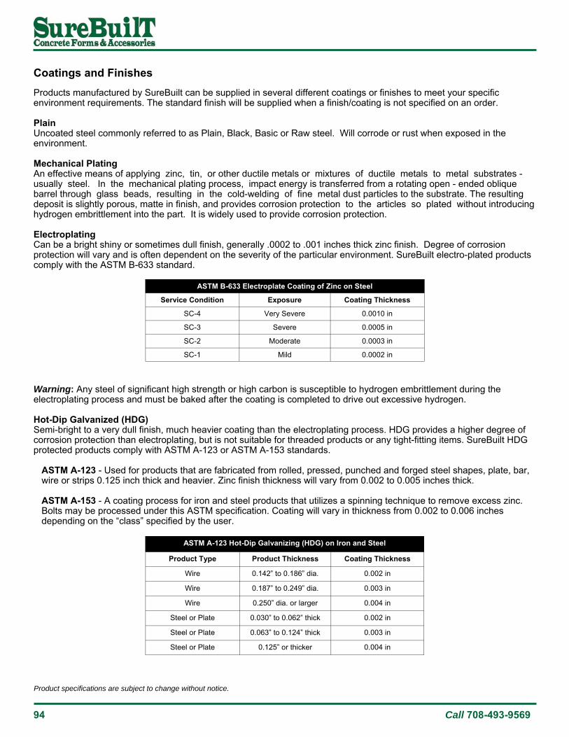
94 Call 708-493-9569
Product specifications are subject to change without notice.
Service Condition Exposure Coating Thickness
SC-4 Very Severe 0.0010 in
SC-3 Severe 0.0005 in
SC-2 Moderate 0.0003 in
SC-1 Mild 0.0002 in
ASTM B-633 Electroplate Coating of Zinc on Steel
Product Type Product Thickness Coating Thickness
Wire 0.142” to 0.186” dia. 0.002 in
Wire 0.187” to 0.249” dia. 0.003 in
Wire 0.250” dia. or larger 0.004 in
Steel or Plate 0.030” to 0.062” thick 0.002 in
ASTM A-123 Hot-Dip Galvanizing (HDG) on Iron and Steel
Steel or Plate 0.063” to 0.124” thick 0.003 in
Steel or Plate 0.125” or thicker 0.004 in
Coatings and Finishes Products manufactured by SureBuilt can be supplied in several different coatings or finishes to meet your specific environment requirements. The standard finish will be supplied when a finish/coating is not specified on an order. Plain Uncoated steel commonly referred to as Plain, Black, Basic or Raw steel. Will corrode or rust when exposed in the environment. Mechanical Plating An effective means of applying zinc, tin, or other ductile metals or mixtures of ductile metals to metal substrates - usually steel. In the mechanical plating process, impact energy is transferred from a rotating open - ended oblique barrel through glass beads, resulting in the cold-welding of fine metal dust particles to the substrate. The resulting deposit is slightly porous, matte in finish, and provides corrosion protection to the articles so plated without introducing hydrogen embrittlement into the part. It is widely used to provide corrosion protection. Electroplating Can be a bright shiny or sometimes dull finish, generally .0002 to .001 inches thick zinc finish. Degree of corrosion protection will vary and is often dependent on the severity of the particular environment. SureBuilt electro-plated products comply with the ASTM B-633 standard.
Warning: Any steel of significant high strength or high carbon is susceptible to hydrogen embrittlement during the electroplating process and must be baked after the coating is completed to drive out excessive hydrogen. Hot-Dip Galvanized (HDG) Semi-bright to a very dull finish, much heavier coating than the electroplating process. HDG provides a higher degree of corrosion protection than electroplating, but is not suitable for threaded products or any tight-fitting items. SureBuilt HDG protected products comply with ASTM A-123 or ASTM A-153 standards.
ASTM A-123 - Used for products that are fabricated from rolled, pressed, punched and forged steel shapes, plate, bar, wire or strips 0.125 inch thick and heavier. Zinc finish thickness will vary from 0.002 to 0.005 inches thick. ASTM A-153 - A coating process for iron and steel products that utilizes a spinning technique to remove excess zinc. Bolts may be processed under this ASTM specification. Coating will vary in thickness from 0.002 to 0.006 inches depending on the “class” specified by the user.

Product specifications are subject to change without notice.
www.surebuilt-usa.com 95
Epoxy Coating A slick, shiny epoxy coating applied to a finished product by means of the electrostatic or fluidized bed method. Coating thickness will vary from .005 inches to .012 inches. Epoxy coatings are very effective corrosion protection in hostile environments such as around or over salt water, or high chemical contaminated areas. Stainless Steel Stainless steel offers high corrosion resistance in any environment. Type 304 stainless steel is generally used (unless otherwise specified) by SureBuilt. It is non-magnetic and can be painted without special preparation. Caution: Corrosion may occur on exposed metal products when architectural precast members are etched or acid washed. The amount of corrosion will be dependent on the acidity of the wash and/or the type of chemicals used. Safe Guarding Against Embrittlement Carbon steels, cold-worked steels and heat treated steels are susceptible to embrittlement in both electroplating and hot-dip galvanizing operations. Any severely cold-worked steel must be stress-relieved from strain aging by baking prior to electro-plating or hot-dip galvanizing. Warning: Products manufactured from high carbon steel that is electro-plated or hot-dip galvanized must be properly heat treated to minimize embrittlement. Failure to properly heat treat these products may compromise their safe working loads and result in a premature failure of the product. Warning: Any steel of significant high strength or high carbon is susceptible to hydrogen embrittlement during the electroplating process and must be baked after the coating is completed to drive out excessive hydrogen. Applicable ASTM documents:
ASTM A-143 "Safe Guarding Against Embrittlement" ASTM A-153 "Zinc Coating (hot dip) on Iron and Steel Hardware" ASTM A-165 "Electro-Deposited Coatings of Cadmium on Steel" ASTM B-633 "Electro-Deposited Coatings of Zinc"
Example Coating Specifications:
Electro-Plate - "Electro-Plate to ASTM B-633 Specification. Service Condition SC-4. Provide embrittlement relief, if necessary." Hot Dip Galvanize - "Hot Dip Galvanize to ASTM A-153, Class A. Provide embrittlement relief, if necessary."
ASTM A-153 Hot-Dip Galvanizing (HDG) on Iron or Steel Hardware
Product Type Product Thickness Coating THickness
Casting A 0.004 in
Steel—3/16” and thicker B1 0.004 in
Steel—3/16” and thicker B2 0.003 in

96 Call 708-493-9569
Product specifications are subject to change without notice.
Coil Bolt Penetration The most common type of insert failure is caused by the lack of sufficient bolt penetration through the coil. Under load, inadequate bolt penetration will cause the upper part of the coil to “unwind” and pull out. This is commonly referred to as the "corkscrew" effect. Coil Bolt Considerations: 1. Failure to properly tighten a coil bolt can result in the inability of the coil bolt to fully penetrate the coil of the insert. 2. Excessive insert setback in the concrete can result in the inability of the coil bolt to fully penetrate the coil of the insert. 3. Worn threads on a coil bolt will render the bolt ineffective and will result in inadequate thread engagement. 4. A coil bolt of inadequate length to fully penetrate the Insert coil will produce a corkscrew type of failure. The insert coil
cannot carry the required load when only partially engaged. 5. Reference the Minimum Coil Penetration Table on page 24.
Caution: Coil bolts should be periodically inspected and replaced for wear or bending. Worn or bent bolts should be discarded immediately. Never use a worn or bent bolt and never attempt to straighten a bent bolt. Edge Lifting When an insert/anchor is located in the edge of a concrete panel for the purpose of lifting and handling of the panel, the concrete on the topside of the insert/anchor will carry the entire applied load unless special provisions are implemented. The upward force on an insert, from the bolt and compressive force from the lifting plate, combine to quickly overload the concrete on the topside of the insert/anchor. The loss of the concrete above the insert/anchor can result in the insert breaking and loss of the panel. One means of increasing edge lift capacity is to strengthen the concrete over the insert with shear bars or stirrup assemblies. This process will reinforce the concrete, preventing total loss of the concrete and allow the insert/anchor to remain in the panel. Always use the proper style and capacity insert/anchor for edge lifting. Never use a two-strut insert. A properly selected insert/anchor will not break if the concrete above it fails. This will allow the panel to be positioned with only minor patching required.
P
P
F
Minimum Coil Penetration

Product specifications are subject to change without notice.
www.surebuilt-usa.com 97
Lifting Hardware All lifting hardware is subject to wear, abuse, bending, overloading, alterations and corrosion. The user must continually inspect the item to determine its usable condition. If the product shows any problem or is not in good working condition, then the item should be discarded or returned for repair and/or service. The frequency of inspection is determined by how often the product is used, length of use and the environment in which it is used. Example: When the Double Swivel Lift Plate (SBDSLP1) with 1” bolt diameter is pulled at an angle producing 3,000 lbs. vertical load and 3,000 lbs. horizontal load, then the following information applies: V = (2e/d) H = 1.0 (3,000) = 3,000 lbs. additional load on the insert due to the horizontal force component. Total applied load = PT PT = Vertical component load + (2e/d) H PT = 3,000 + 3,000 = 6,000 lbs. Total Tension Load An insert with a Safe Working Load (SWL) greater than 6,000 lbs. is required. Lifting Plates When using a Lifting Plate in conjunction with cast-in-place inserts, a combination of forces with small lever arms become factors of concerned. Reference the sketches shown below. Dimension "d” is an assumed constant subject to the location of "R", the resultant force exerted by the reaction of the plate on the concrete. Lifting Plate considerations: 1. If the lifting plate is loosely tightened, the location of "R" will be at the extreme edge/corner of the plate and "d"
becomes the plate width divided by 2. 2. If the lifting plate is properly tightened with the attachment bolt, then the generally accepted stress pattern will be
triangular or trapezoidal. 3. During initial and low loads the "R" force moves from the toe of the plate towards the center of the plate. As the load
increases, the plate attempts to flex. The maximum movement is most likely at the midpoint of the plate, between the bolt centerline and the toe of the plate. Taking a conservative approach, "d divided by 2" is the theoretical location of the "R" force, resulting in a higher load added to the vertical component load.
Lifting Hardware
P/N Bolt Dia (2e/d)
SBSLP34 3/4” 0.67
SBSLP1 1” 0.67
SBDSLP1 1” 1.00
SBDSLP114 1-1/4” 0.75
SBDSLP112 1-1/2” 0.75
SBELP34 3/4” 3.00
SBELP1 1” 3.00
SBLA1 1” 2.00
SBLA114 1-1/4” 2.00
SBLA112 1-1/2” 2.00
Swivel Plate Application
H
T P
Shear Force
R
d
d/2
V
e
SBDSLP or
SBSLP
Lift Plate Application
H
T P
V
R
d
d/2
Shear Force
SBELP or
SBLA

98 Call 708-493-9569
Product specifications are subject to change without notice.
4. Using basic equations, a pair of force couples must be equal to zero: H(e) = V(d/2) and V = (2e/d)H V = vertical force on the insert. H =horizontal force on the lifting plate.
Lifting Plate example: When the Double Swivel Lift Plate (SBDSLP1) with a 1” bolt diameter is pulled at an angle producing 3,000 lbs .vertical load and 3,000 lbs. horizontal load, then the following information applies: V = (2e/d) H = 1.0 x 3,000 = 3,000 lbs. additional load on the insert due to the horizontal force component. Total applied load = PT PT = Vertical component load + (2e/d) H PT = 3,000 + 3,000 = 6,000 lbs. Total Tension Load In this example, an insert with a safe working load greater than 6,000 lbs. must be used. Inclined slings: When rigging is selected where the sling lines are inclined, it is important to measure the angle b (beta). The angle will cause an increase in the anchor loading due to the horizontal force components. Reference the sketched examples: 1. The angle is 60° and from the table below, the load factor is 1.16.
Therefore, P1 load = 1.16 x weight of the concrete element divided by 2. 2. The angle is 15° and from the table below, the load factor is 1.01.
Therefore, P1 load = 1.01 x weight of the concrete element divided by 2.
Sling Angle b 90° 75° 60° 45° 30°
Load Factor 1.41 1.26 1.16 1.08 1.04
Sling Angle Load Factors
120°
2.00
105°
1.64
15°
1.01
PT
P1 P2
b = 60° 60° Sling Angle
PT
P1 P2
b = 15° 15° Sling Angle

Product specifications are subject to change without notice.
www.surebuilt-usa.com 99
Example 1 - Two-part chain slings: Determine the anchor load, anchor size and concrete psi required for a rectangular concrete beam 12” deep, 3’ wide and 24’ long. The beam has form adhesion at the bottom surface only and a sling angle of 45°. Concrete dead weight = 12” /12” x 3’ x 24’ x 150 lbs. = 10,800 lbs. Form adhesion (steel form) = 12” /12” x 24’ x 25 lbs. = 600 lbs. Total Load (PT) = 11,400 lbs. Now apply the load factor for the 45° sling angle and realizing that P1 = P2 = PT then P1 = 11,400/2 x 1.08 = 6,156 lbs. per anchor To adequately lift the beam would require an anchor like the 4 ton Two-Hole Anchor (P/N SBTHA584) with Tension Bar rated at 8,000 lbs. SWL in 3,000 psi concrete.
Example 2 - Four slings attached at slab corners: When four fixed length slings are used to lift and handle a concrete element, often one of the slings will be longer than the rest. This will force two of the embedded anchors to carry the total load and the other two anchors to do little more than keep the slab balanced. Determine the anchor load, anchor size and concrete psi required for a slab 12’ x 11’ x 16” using a sling incline angle of 30° and having form adhesion at the bottom surface only. Concrete dead weight = 12’ x 11’ x 16”/12” x 150 lbs. = 26,400 lbs. Form adhesion (steel form) = 12’ x 11’ x 20 lbs. = 2,640 lbs. Total Load (PT) = 29,040 lbs. P1 = 29,040/2 (only two anchors working) x 1.04 per anchor = 15,100 lbs. per anchor To adequately lift and handle, the example slab would require an anchor like the 10 ton x 10” Ring-Lift Anchor (P/N SBDFFA3410) rated at 20,000 lb SWL in 3,500 psi concrete.
3’0”
12”
24’0”
P
P1
P2
45°
Example 1
Load Carrying
Relaxed
30°
Example 2

100 Call 708-493-9569
Product specifications are subject to change without notice.
Sling Angle Factor Additional forces come to bear on an anchor from oblique pulls caused by the sling angle. As the angles increases, the cable load increases and transfers an even larger load to the anchor. Angles greater than 90° are not safe and must not be used. To calculate the load on the anchor, refer to the accompanying table. Move across the table to the sling angle being used and multiply the corresponding magnification factor by the dead load of the precast element.
Concrete Strength Adjustment Factors To convert the allowable tension load for an unreinforced anchor from listed concrete strength of 3,500 psi to a greater or lesser concrete strength, multiply 3,500 psi by the factor indicated in the table. Note: These factors are for use with tension applications only. Do not use these factors for shear applications without consulting with SureBuilt to make sure there are no other limitations. Note: To maintain the needed 4:1 safety factor the new value must be less than 25% of the listed ultimate mechanical value of the selected anchor.
Concrete Strength Adjustment Factors
To Increase For Greater Concrete Strength
Convert From Multiply By
3,500 psi to 4,000 psi 1.07
3,500 psi to 4,500 psi 1.13
3,500 psi to 5,000 psi 1.19
Convert From Multiply By
3,500 psi to 3,000 psi 0.92
3,500 psi to 2,500 psi 0.84
3,500 psi to 2,000 psi 0.75
To Decrease For Lesser Concrete Strength
Sling Angle
Sling Angle b 90° 75° 60° 45° 30°
Load Factor 1.41 1.26 1.16 1.08 1.04
Sling Angle Factor
120°
2.00
105°
1.64
15°
1.01
Note: Additional factors to consider include sling length, crane type and jobsite conditions. Additional impact factors may apply.

Product specifications are subject to change without notice.
www.surebuilt-usa.com 101
Concrete Shear Cone The shear cone is that area of concrete around the anchor that withstands the stress during lifting.
Typical Wire Sizes and Strengths
Nominal Wire Dia (inches)
Wire Grade
AISI and SAE Number
Approximate Min Yield Tension
Approximate Min Ultimate
Tension
Approximate Min
Shear
0.440 MHC 1040 13,000 lbs 15,000 lbs 10,200 lbs
0.375 LC 1018 8,250 lbs 9,350 lbs 6,360 lbs
0.375 LC 1008 6,500 lbs 8,250 lbs 5,700 lbs
0.306 LC 1018 5,400 lbs 6,200 lbs 4,240 lbs
0.306 LC 1008 4,400 lbs 5,450 lbs 3,750 lbs
0.283 LC 1018 4,700 lbs 5,400 lbs 6,650 lbs
0.262 LC 1008 2,700 lbs 3,500 lbs 2,400 lbs
0.223 MHC 1035 3,400 lbs 4,000 lbs 2,708 lbs
0.218 LC 1008 2,100 lbs 2,800 lbs 1,870 lbs
Concrete Surface
P P P
Surface Area Assumed Shear Cone
E = Embedded Depth

102 Call 708-493-9569
Product specifications are subject to change without notice.

Product specifications are subject to change without notice.
www.surebuilt-usa.com 103
2-Hole Anchor ............................................................... 26 Anchor 500 (Easy-Lift) ................................................... 77 Anchor Rail .................................................................... 80 Bar Chairs, Plastic ......................................................... 90 Bearing Pads ................................................................. 81 Bolt & Wing Nut (Easy-Lift) ............................................ 76 Bolt & Wing Nut (Ring-Lift) ............................................ 59 Bolt & Wing Nut (Uni-Lift) .............................................. 67 C-Connector Pin ............................................................ 89 Cable Lifter (Ring-Lift) ................................................... 56 Cable Loop Anchor ........................................................ 78 Chain Lifter (Ring-Lift) ................................................... 56 Chord Connector ........................................................... 82 Coatings ........................................................................ 94 Coil Insert - Criss Cross .................................................. 8 Coil Insert - Double Flare ................................................ 8 Coil Insert - Flare ............................................................. 7 Coil Insert - L-Leg ............................................................ 9 Coil Insert - Loop ............................................................. 6 Coil Insert - Open Coil ..................................................... 9 Coil Insert - Thin Slab .................................................... 10 Coil Nut ......................................................................... 14 Coil Rod ........................................................................ 13 Coil Rod Coupler ........................................................... 13 Coil Tie 2-Strut ................................................................ 4 Coil Tie 4-Strut ................................................................ 5 Column Base Connector ............................................... 83 Double Swivel Lift Plate ................................................. 15 Double Tee Anchor ....................................................... 31 Drop-Forged Foot Erection Anchor ............................... 44 Ductile Ferrule Insert ..................................................... 22 Edge Connector ............................................................ 86 Edge Lift Bracket ........................................................... 16 Edge Lift Shear Bar ....................................................... 69 Edge Protector - Plastic ................................................. 91 Erection Anchor ............................................................. 34 Erection Anchor w/Shear Plate...................................... 35 Ferrule Insert ................................................................. 18 Ferrule Insert - Flare ...................................................... 19 Ferrule Insert - L-Leg ..................................................... 20 Ferrule Insert - Loop ...................................................... 18 Ferrule Insert - Open Coil .............................................. 21 Ferrule Insert - Thin Slab ............................................... 20 Ferrule Insert - Wing ...................................................... 19 Flat Washer ................................................................... 14 Foot Anchor ................................................................... 28 FRP Truss ..................................................................... 88 HD Sandwich Panel Erection Anchor ............................ 46 HD Sandwich Panel Erection Anchor w/Shear Plate ..... 47 Lift Angle Bracket .......................................................... 16 Lifter (Ring-Lift).............................................................. 55 Lifter (Uni-Lift)................................................................ 70
Lifting Guidelines ........................................................... 97 Locator Plug .................................................................. 12 M-Connector Pin ............................................................ 89 Magnet Plate (Easy-Lift) ................................................ 76 Magnet Plate (Ring-Lift) ................................................. 59 Magnet Plate (Uni-Lift) ................................................... 68 Mounting Plate (Easy-Lift) ............................................. 76 Mounting Plate (Ring-Lift) .............................................. 59 Mounting Plate (Uni-Lift) ................................................ 67 Patch Cap ...................................................................... 91 Pick-Up Insert ................................................................ 11 Plastic Chair .................................................................. 90 Plastic Insert .................................................................. 24 Plastic Plug .................................................................... 23 Plate Anchor .................................................................. 33 Precast Insert ................................................................ 24 Recess Former (Easy-Lift) ............................................. 74 Recess Former (Ring-Lift) ............................................. 57 Recess Former (Uni-Lift) ............................................... 67 Ring-Lift Lifter ................................................................ 55 Safety ............................................................................ 93 Sandwich Panel Erection Anchor .................................. 46 Sandwich Panel Erection Anchor w/Shear Plate ........... 47 Setting Plug ................................................................... 12 Shear Bar ...................................................................... 42 Shear Cone ................................................................. 101 Shim Pack - Plastic ........................................................ 91 Slab Bolsters - Plastic .................................................... 91 Slant Anchor .................................................................. 85 Sling Angle .................................................................. 100 Straight Leg Erection Anchor w/Shear Plate ................. 43 Straight Leg Insert ......................................................... 30 Swivel Lift Plate ............................................................. 15 T-Bar Anchor ................................................................. 27 Tension Bar ................................................................... 42 Threaded Plug ......................................................... 12, 23 Truss (FRP) ................................................................... 88 Truss (Wire) ................................................................... 87 Two-Hole Anchor ........................................................... 26 Uni-Anchor (Ring-Lift) .................................................... 29 Uni-Eye Anchor (Uni-Lift) ............................................... 66 Uni-Lift Anchor (Uni-Lift) ................................................ 62 Uni-Lift Lifter .................................................................. 70 Utility Anchor (Easy-Lift) ................................................ 74 Utility Anchor w/ Snap Wires (Easy-Lift) ........................ 75 Wall Base Connector ..................................................... 84 Wavy Tail Anchor .......................................................... 32 Wire Truss ..................................................................... 87 X-Foot Erection Anchor ................................................. 37 X-Foot Erection Anchor w/Shear Plate .......................... 39 X-Foot Erection Anchor w/45° and Shear Plate ............. 41

840 South 25th AveBellwood, IL 60104708-493-9569www.surebuilt-usa.com
08/21
Articulated Waler – Radius forming from 20’ to 180’, with 3/4” plywood, aluminum or wood beams, and an adjustable waler.
Bar Support – Wire slab bolsters and high chairs, with optional epoxy-coat, plastic-dip, plastic-tip or plate, to meet almost any slab requirement.
Bridge Deck – Overhang brackets and hangers provide an efficient deck forming solution for precast concrete or steel I-beam bridge structures.
Coil Ties – 2-Strut and 4-Strut designs, in standard and heavy-duty capacities, with optional cones, waterseals or custom combination, for job-built forming.
Euro Rod – 15mm and 20mm taper ties, she-bolts, inner ties, washers and wing nuts compatible with European-brand forming systems.
Floor Dowels – Plates, sleeves, baskets and joint nosings for high-performance concrete floors.
Pipe Braces – Contractor-preferred braces, with rated capacities and lengths ranging from 7’6” to 62’6”, for almost any forming application.
Precast – Inserts, anchors, connectors and lifting systems for efficient precast concrete production.
Self-Riser – Integrated hydraulic system for multi-story building cores that virtually eliminates crane time.
Shoring – A conventional 10K load/leg system, with base plates, cross braces, screw jacks and U-heads, for productive deck support.
Snap Ties – Ties and brackets, with ¾” plywood and 2x4 lumber, create a simple and effective plywood forming system.
Staybox – A pre-engineered and pre-assembled rebar keyway that simplifies forming at wall and deck intersections.
Stud Rail – A reinforced column-to-deck connection that reduces shearing, transfers load further into the slab and eliminates column capitals.
SureCurve™ – Concrete tanks and curved walls quickly take shape with this flexible and reusable gangform system.
SurePly™ – An industry-recognized handset system, with more than 80 standard panel and filler sizes, for almost any forming application.
Tilt-Up – A start-to-finish system of lifting inserts, plates and hardware for tilt-up panel construction.
Walers – Double channel walers align panels, carry taper tie loads and maximize the surface area of almost any gang.