precautions for use...precautions for use people's injuries and property damages. • the...
TRANSCRIPT
Precautions for use
people's injuries and property damages.• The following suggestions show the degree of danger and damage caused
• The following graphic suggestions describe the types of precautions to be followed.
The following safety precautions are given throughout this manual. They mustbe strictly followed to protect those who install, use or maintain this product aswell as to prevent other
Be sure to read the following
WARNING
WARNINGIndicates a situation where disregarding the suggestions could result in death or serious injury.
CAUTION
CAUTIONIndicates a situation where disregarding the suggestions could result in injury or product damage.
Indicates a matter which should be performed without fail.
Indicates a matter which is forbidden.
In this instruction manual, some procedures require a qualified in-shop maintenance person orindustry specialist. For such instructions, a qualified person must take care of the jobs.• Otherwise an electric shock, machine trouble, or a serious accident may result.• Replacing the machine parts, inspecting and maintaining the machines, and troubleshooting must be
assigned only to a qualified in-shop maintenance person or industry specialist. This booklet givesinstructions that hazardous jobs in particular must be handled by an industry specialist. Qualified in-shopmaintenance persons and industry specialist are defined as follows.
Qualified in-shop maintenance persons• A qualified in-shop maintenance person must have experience in maintaining amusement machines. Under
the supervision of an amusement machines shop owner or manager, he or she routinely assembles, installs,inspects and maintains the amusement machines, or replaces their component units and consumable parts,in the amusement machines workshop and/or location.
Jobs handled by qualified in-shop maintenance persons•Assembling, installing, inspecting and maintaining amusement machines and replacing their component units
and consumable parts.
Industry specialist•An industry specialist must be engaged in designing, manufacturing, inspecting and servicing amusementmachines. Or he or she must have an education in electrical, electronic and mechanical engineering, androutinely maintain and repair amusement machines.
Jobs handled by industry specialist•Assembling and installing amusement machines and repairing and adjusting their electrical, electronic andmechanical component parts.
• The following graphic suggestions describe the types of precautions to be followed.
Indicates a matter of which care should be taken.
Be sure to consult your nearest dealer whensetting up, moving or transporting this product.• This product should not be set up, moved or
transported by any one other than an industryspecialist. Doing so could result in injury or productd a m a g e .
• When installing this product, set the 4 leg levelersevenly on the floor and make sure that the productis installed stably in a horizontal position. Unstableinstallation may result in injury or accident.
• When installing this product, use caution not toapply undue force to opening and closing parts andother movable parts. Otherwise, injury andaccident may result, or the product may bed a m a g e d .
This product is an indoor game machine. Neverset the game up outside.• Setting this product up outside could result in
accidents or equipment failure.
Do not set the game up near emergency exits.• Doing so could block exits in time of emergency
and could result in death or serious injury.
Do not set the game up.• In a place exposed to rain or moisture.• In a place exposed to direct sunlight.• In a place exposed to direct heat from air-
conditioning and heating equipment, etc..• Near hazardous flammable substance such as
thinner and kerosene.• Otherwise an accident or malfunction may result.
Do not place containers holding chemicals orwater on or near the game machine.• Electrical shock or damage could be caused by
water or foreign matter entering the inside of them a c h i n e .
Do not place objects near the ventilating holes.• Doing so could cause the internal temperature to
rise excessively, resulting in fire or equipmentf a i l u r e .
Do not bend the power cord by force or placeheavy objects on it.• Doing so could result in electrical shock or fire.
Never plug or unplug the power cord with weth a n d s .• Doing so could result in electrical shock or fire.
Never unplug the game by pulling the powerc o r d .• Doing so could damage the cord, resulting in
electrical shock or fire.
Be sure to use indoor wiring for within thespecified voltage range. For extension cord,use indoor wiring of the specified rating ormore.• Failure to do so could result in fire or equipment
failure.
Be sure to use the attached power cord.• Otherwise a fire or machine trouble may result.
Never plug more than one cord at a time in theelectrical receptacle.• Doing so could result in fire or electrical shock.
Do not lay the power cord where people walkthrough. You may trip on or stumble over thecord. • You may stumble down and get injured, or
damage the power cord.
Be sure to ground this product.• Otherwise an electrical shock or machine
trouble may be caused.
Do not apply a strong force for moving themachine.• Otherwise, it may result in an accident or
breakage of the units.
Clearance of 100 mm (3.94in) or more shouldbe created between the game machine andwalls. • Otherwise the machine (s) cannot be ventilated
well, resulting in malfunction.
Do not change the DIP switch setting of thisproduct to other than factory setting.• Otherwise, the game can not be played
properly.
Setting Up
WARNING CAUTION
Inspection and cleaning / Moving and transportation
P E R C A U T I O N IN HANDLING
• When setting up, inspecting. maintaining,moving or transporting this product, followthe procedures and instructions set forth inthis manual and perform such work safely.
• Do not set up, handle, inspect, maintain,move or transport this product underconditions equivalent to the condition of"WARNING" or "CAUTION" specified in thismanual.
• If a new owner is to have this product as aresult of transfer, etc., be sure to give thismanual to the new owner.
Be sure to turn OFF the main power switchand unplug the power cord from thereceptacle before inspecting or cleaning themachine.• Failure to do so could result in electrical shock.
When replacing parts, be sure to use parts ofthe correct specifications. Never use partsother than the specified ones.• Using improper parts could result in fire or
equipment failure.
There is high voltage inside the machine.Only qualified industry specialist is allowed toopen the machine's back door. With the backdoor open, be very careful not to touch themonitor and its nearby parts.• Otherwise an accident or electric shock may
result. Never allow anyone else butANDAMIRO's service engineers to open theupper door on the back of the machine.
If the sub power switch of the service panel isturned OFF without turning OFF the mainpower switch of the power supply unit, someparts in the units remain live. When openingthe back door, be sure to turn OFF the mainpower switch and unplug the power cord fromthe receptacle.• Otherwise, there may be danger an accident or
electric shock.
Strictly refrain from disassembly and repair ofparts which are not indicated in this manual,as well as settings and remodeling.• Otherwise, a fire, malfunction or trouble may
result. In case of any trouble, ask your nearestdealer for repairs and other services.ANDAMIRO will not resume any responsibilityfor the damage to the product attributable todisassembly and repair of parts which are notindicated in this manual, as well as settings andremodeling.
To clean the game machine, wipe it with a softcloth dampened in a neutral detergent.• Using thinner of other organic solvent or alcohol
may decompose the material.• Electrical shock or equipment failure could be
caused by water entering the inside of themachine.
The game machine contains parts such as themonitor, electronic components and precisioncomponents which are sensitive to vibrationsand impacts, Great care therefore should betaken when moving and transporting thegame machine.Be sure not to let the machine tip over.
Before moving the machine, be sure to turnOFF the main power switch, unplug the powercord from the receptacle and remove thepower cord form the machine.• Stepping on or tripping over the power cord may
result in an accident or damage to the machine.
Before moving the machine, be sure to fullylift the four levelers and move it on thecasters.• Otherwise, an accident, breakage or trouble
may result.
Do not apply a strong force for moving themachine.• Otherwise, it may result in an accident or
breakage of the units.
WARNING CAUTION

8
S P E A K E RBILLBOARD PA N E L
C RT ( 2 5”~ 2 9”)
FRONT CASE
BUTTON PA N E L
MONITOR MASK
FRONT DOOR
MONEY BOX DOOR-DOWN
MONEY BOX DOOR-TOP
BACK CASE
SIDE COVER
1-1) NAME OF EACH PA RT
1. NAME OF EACH PART
10
STOP
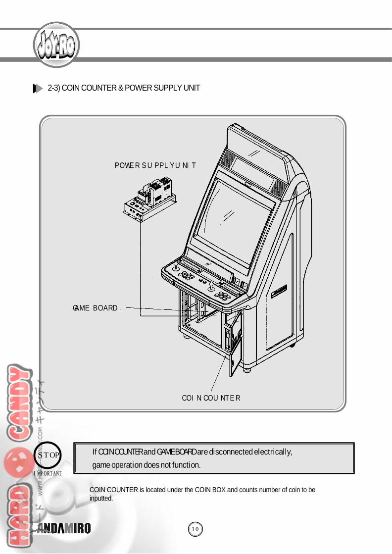
POWER SUPPLY UNIT
GAME BOARD
COIN COUNTER
◎ COIN COUNTER is located under the COIN BOX and counts number of coin to bei n p u t t e d .
2-3) COIN COUNTER & POWER SUPPLY UNIT
IMPORTANT
◎ If COIN COUNTER and GAME BOARD are disconnected electrically,
game operation does not function.

3. NOTICES IN TREATMENT
12
- When installing or checking machine, you must follow the following notices toenable users to enjoy game safely.
◎ Check the usage voltage, and then turn on the power button.◎ Do not insert or remove plug.◎ Do not use a non-standard fuse.◎ If GAME BOARD and other connection part are inserted completely, it is very risky. Please
check whether access is completed or not.◎ Temperature for operation must be maintained between 5℃ and 40℃.◎ If you clean the surface of CRT, you can use smooth and dry cloth and cannot diluent,
which is diluted with chemicals such as benzene.
- This device is indoor game machine. Do not install and operate it outside. In installation inside, you must avoid the following places.
◎ If you install this product in the inclined or unstable place, it can cause damage or injury. ◎ If you install this product in humid, dusty, water(rainwater)-spattered place, it can cause
electric shock and fire.◎ Do not place candle and cigarette on product, or install near heating engine. ◎ Do not place very flammable chemicals or violently impactive things.
3-1) NOTICES IN TREAT M E N T
3-2) PRECAUTIONS IN TREAT M E N T
※ For static electricity
◎When power supply is cut or off, you can feel turning on an little electric current intouching monitor. But, this is resulted from staticc electricity and will not injure people.

14
W A R N I N G
Acceptable maximum current of this machine is 10A with outlet. You can
connect up to 6 devices. When you connect 7 devices or more, it
is prohibited strictly because the current is higher than 10A of the
designated current, it is very
In transporting
machine, follow the
method as shown in
the right figure.
4-2) INSTA L L AT I O N
4-3) MACHINET R A N S P O RTAT I O N
CASTER ROLLER
S T O P P E R
16
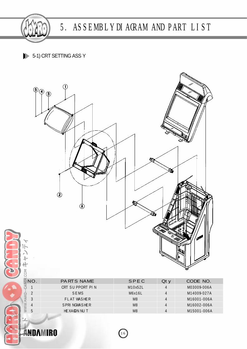
5-1) CRT SETTING ASS’Y
5. ASSEMBLY DIAGRAM AND PART LIST
M 0 3 0 0 9 - 0 0 6 A
M 1 4 0 0 9 - 0 2 7 A
M 1 6 0 0 1 - 0 0 6 A
M 1 6 0 0 2 - 0 0 6 A
M 1 5 0 0 1 - 0 0 6 A
CRT SUPPORT PIN
S E M S
FLAT WASHER
SPRING WASHER
HEXAGON NUT
M 1 0 x 5 2 L
M 6 x 1 6 L
M 8
M 8
M 8
S P E C Q t y. CODE NO.PA RTS NAMEN O .
1
2
3
4
5
4
4
4
4
4

18
Assemble E on F and check whether CRT position D(MONITOR MASK part of FRONT CASE) and E is suitable.
If you change position of CRT, disassemble E in F, loosen flush BOLT of G, and adjust the position by moving F up
and down.
20
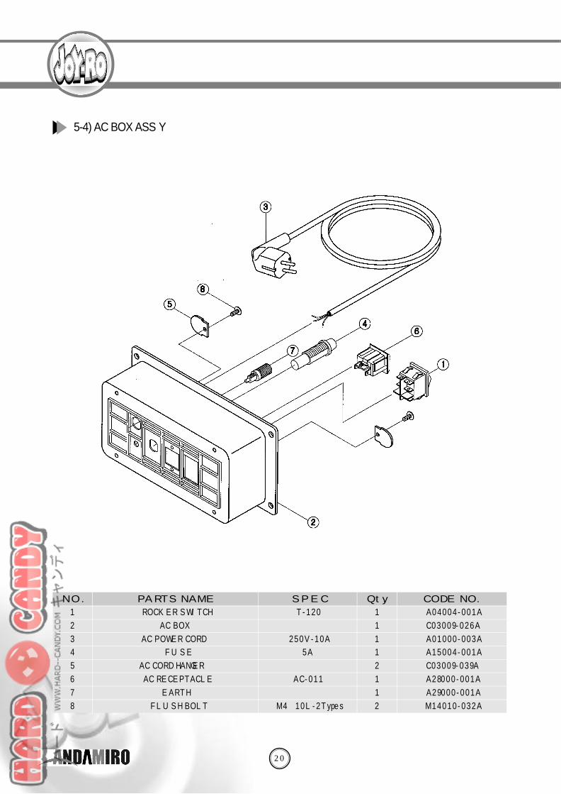
5-4) AC BOX ASS’Y
A 0 4 0 0 4 - 0 0 1 A
C 0 3 0 0 9 - 0 2 6 A
A 0 1 0 0 0 - 0 0 3 A
A 1 5 0 0 4 - 0 0 1 A
C 0 3 0 0 9 - 0 3 9 A
A 2 8 0 0 0 - 0 0 1 A
A 2 9 0 0 0 - 0 0 1 A
M 1 4 0 1 0 - 0 3 2 A
ROCKER SWITCH
AC BOX
AC POWER CORD
F U S E
AC CORD HANGER
AC RECEPTACLE
E A R T H
FLUSH BOLT
T - 1 2 0
2 5 0 V - 1 0 A
5 A
A C - 0 1 1
M 4×1 0 L - 2 T y p e s
S P E C Q t y. CODE NO.PA RTS NAMEN O .
1
2
3
4
5
6
7
8
1
1
1
1
2
1
1
2
22
C 0 3 0 0 9 - 0 2 5 A
M 0 2 0 0 9 - 0 2 2 A
C 0 3 0 0 9 - 0 3 1 A
C 0 3 0 0 9 - 0 3 2 A
C 0 3 0 0 9 - 0 3 3 A
C 0 3 0 0 9 - 0 3 7 A
M 0 2 0 0 9 - 0 2 1 A
C 0 3 0 0 9 - 0 5 1 A
M 0 2 0 0 9 - 0 3 1 A
C 0 3 0 0 9 - 0 4 6 A
A 0 4 0 0 3 - 0 0 5 A
A 1 4 0 0 0 - 0 0 1 A
C 0 3 0 0 9 - 0 5 8 A
M 1 4 0 1 5 - 0 0 5 A
M 1 4 0 1 5 - 0 0 9 A
M 1 4 0 1 5 - 0 1 2 A
M 1 4 0 0 7 - 0 1 6 A
M 1 4 0 0 7 - 0 1 4 A
M 1 5 0 0 1 - 0 0 1 A
M 1 5 0 0 1 - 0 0 2 A
M 1 6 0 0 1 - 0 0 1 A
A 1 0 0 0 2 - 0 0 3 A
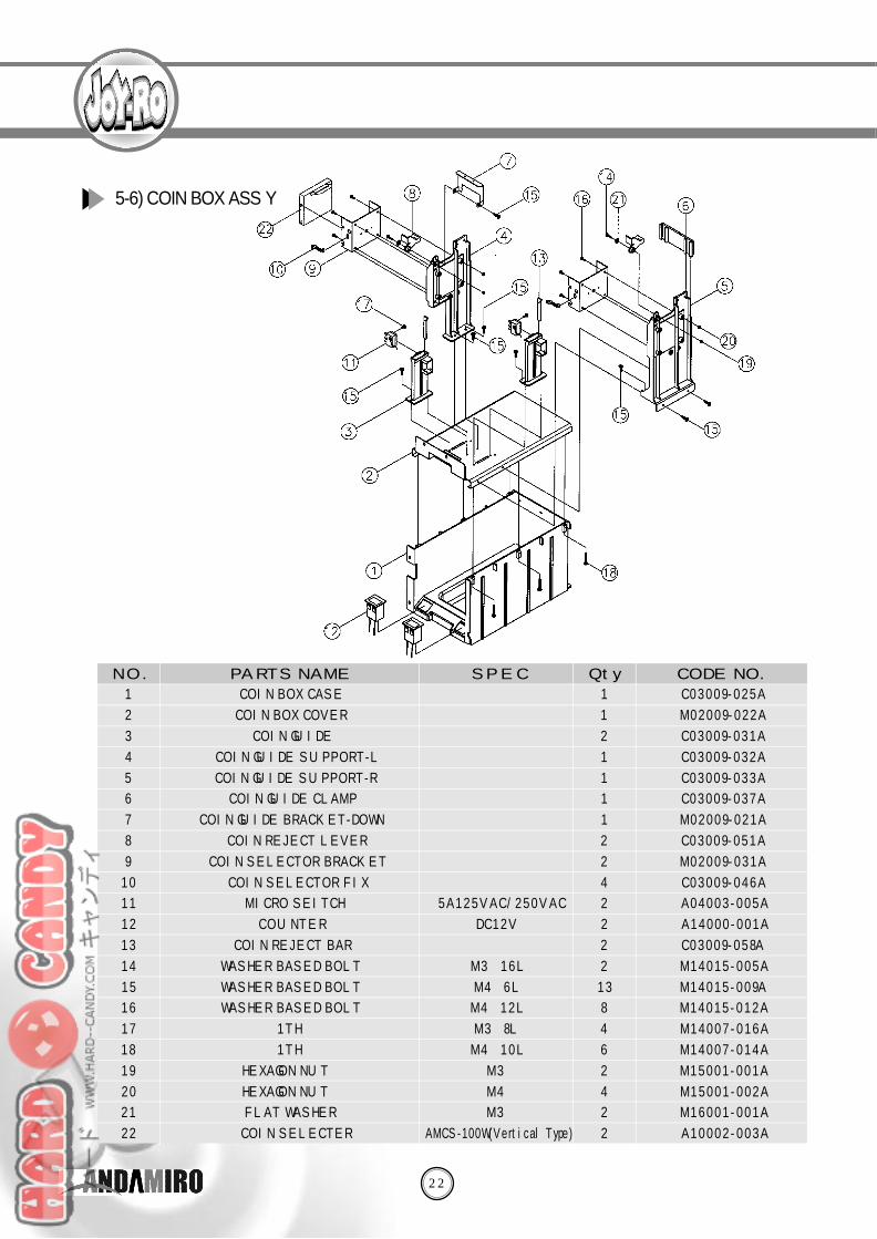
COIN BOX CASE
COIN BOX COVER
COIN GUIDE
COIN GUIDE SUPPORT-L
COIN GUIDE SUPPORT-R
COIN GUIDE CLAMP
COIN GUIDE BRACKET-DOWN
COIN REJECT LEVER
COIN SELECTOR BRACKET
COIN SELECTOR FIX
MICRO SEITCH
C O U N T E R
COIN REJECT BAR
WASHER BASED BOLT
WASHER BASED BOLT
WASHER BASED BOLT
1 T H
1 T H
HEXAGON NUT
HEXAGON NUT
FLAT WASHER
COIN SELECTER
5 A 1 2 5 V A C / 2 5 0 V A C
D C 1 2 V
M 3×1 6 L
M 4×6 L
M 4×1 2 L
M 3×8 L
M 4×1 0 L
M 3
M 4
M 3
AMCS-100W(Vertical Type)
S P E C Q t y. CODE NO.PA RTS NAMEN O .
1
2
3
4
5
6
7
8
9
1 0
1 1
1 2
1 3
1 4
1 5
1 6
1 7
1 8
1 9
2 0
2 1
2 2
1
1
2
1
1
1
1
2
2
4
2
2
2
2
1 3
8
4
6
2
4
2
2
5-6) COIN BOX ASS’Y

24
C 0 3 0 0 9 - 0 2 1 A
M 0 2 0 0 9 - 0 5 1 A
M 1 4 0 1 5 - 0 1 8 A
M 1 4 0 1 5 - 0 2 2 A
M 1 5 0 0 3 - 0 0 6 A
C 0 3 0 1 0 - 0 0 8 A
CORNER CASE
M5 BOLT WASHER
WASHER BASED BOLT
WASHER BASED BOLT
HEXAGON NUT
DOOR FRAME
M 5×1 0 L
M 5×2 5 L
M 8
S P E C Q t y. CODE NO.PA RTS NAMEN O .
1
2
3
4
5
6
2
6
8
5
4
1
5-8) DOOR FRAME ASS’Y
26
C 0 3 0 1 0 - 0 0 9 A
C 0 3 0 1 0 - 0 1 0 A
C 0 3 0 1 0 - 0 0 3 A
C 0 3 0 1 0 - 0 0 2 A
C 0 3 0 0 9 - 0 2 7 A
C 0 3 0 1 0 - 0 2 2 A
M 0 2 0 0 9 - 0 5 1 A
M 0 2 0 1 0 - 0 1 3 A
C 0 3 0 0 9 - 0 5 3 A
M 1 4 0 1 5 - 0 1 0 A
M 1 4 0 1 5 - 0 2 1 A
M 1 4 0 1 5 - 0 2 2 A
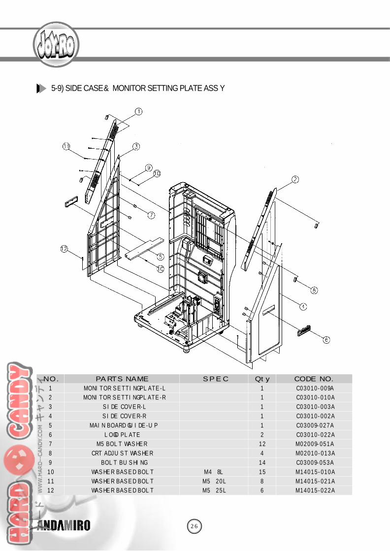
MONITOR SETTING PLATE-L
MONITOR SETTING PLATE-R
SIDE COVER-L
SIDE COVER-R
MAIN BOARD GUIDE-UP
LOGO PLATE
M5 BOLT WASHER
CRT ADJUST WASHER
BOLT BUSHING
WASHER BASED BOLT
WASHER BASED BOLT
WASHER BASED BOLT
M 4×8 L
M 5×2 0 L
M 5×2 5 L
S P E C Q t y. CODE NO.PA RTS NAMEN O .
1
2
3
4
5
6
7
8
9
1 0
1 1
1 2
1
1
1
1
1
2
1 2
4
1 4
1 5
8
6
5-9) SIDE CASE &M O N I TOR SETTING PLATE ASS’Y

28
5 - 11) MAIN BOARD GUIDE ASS’Y
C 0 3 0 0 9 - 0 2 2 A
C 0 3 0 0 9 - 0 3 8 A
C 0 3 0 0 9 - 0 2 9 A
C 0 3 0 0 9 - 0 3 0 A
A M 0 1 - Z Z Z S 0 2 A
M 1 4 0 0 6 - 0 4 1 A
M 1 4 0 1 5 - 0 2 6 A
M 0 2 0 0 9 - 0 5 9 A
M 0 2 0 0 9 - 0 4 6 A
M 0 2 0 0 9 - 0 6 2 A
M 1 4 0 1 5 - 0 1 8 A
M 0 2 0 0 9 - 0 5 0 A
M 0 2 0 0 9 - 0 6 3 A
M 1 5 0 0 3 - 0 0 3 A
MAIN BOARD PANEL
COIN BOX
MAIN BOARD GUIDE
MAIN BOARD GUIDE SUPPORT
KEY ASS’Y
TRUSS BOLT
WASHER BASED BOLT
COIN BOX LOCKING
MAIN PCB LOCK HINGE
MAIN PCB LOCK SUPPORT
WASHER BASED BOLT
DOOR LOCK
COIN BOX LOCK SUPPORT
FLANGE NUT
0 7 2 0
M 3×8 L - 2 T y p e s
M 4×8 L - 2 T y p e s
M 5×1 0 L
M 5
S P E C Q t y. CODE NO.PA RTS NAMEN O .
1
2
3
4
5
6
7
8
9
1 0
1 1
1 2
1 3
1 4
1
1
2
2
1
3
8
1
1
1
4
1
1
2
30
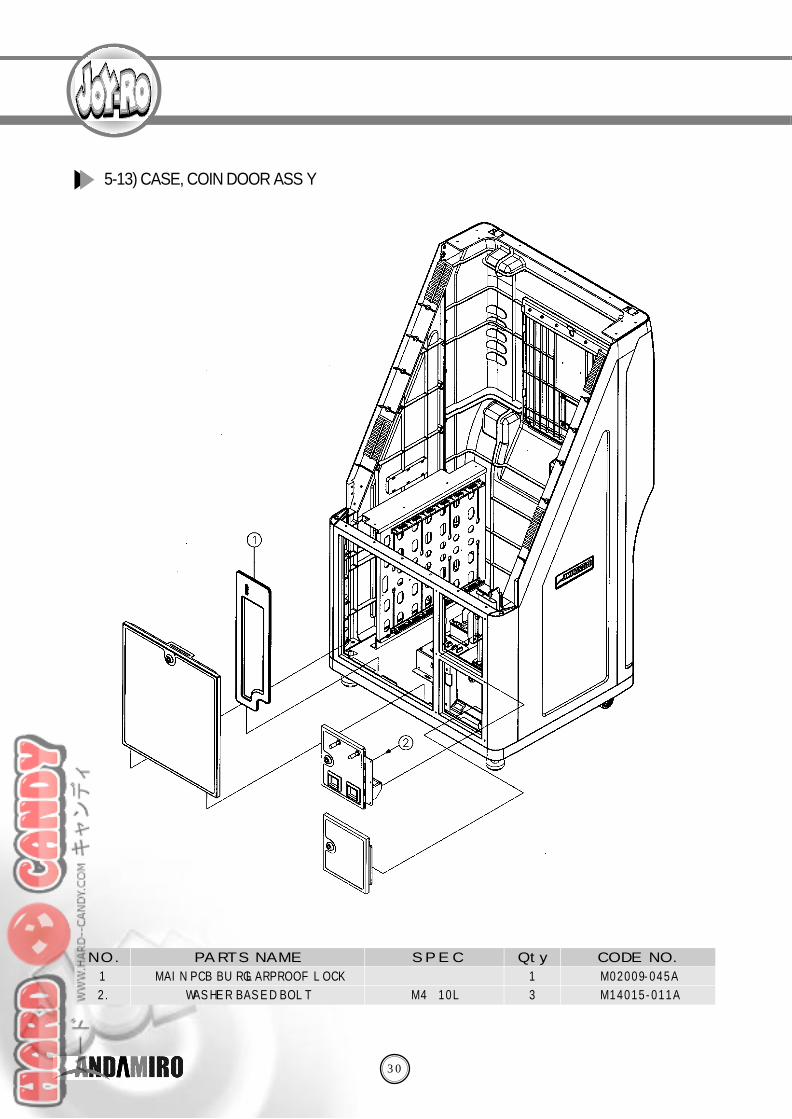
M 0 2 0 0 9 - 0 4 5 A
M 1 4 0 1 5 - 0 1 1 A
MAIN PCB BURGLARPROOF LOCK
WASHER BASED BOLT M 4×1 0 L
S P E C Q t y. CODE NO.PA RTS NAMEN O .
1
2 .
1
3
5-13) CASE, COIN DOOR ASS’Y
32
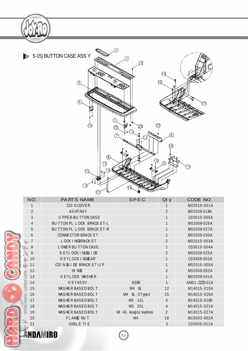
5-15) BUTTON CASE ASS’Y
M 0 2 0 1 0 - 0 0 1 A
M 0 2 0 0 9 - 0 1 8 A
C 0 3 0 1 0 - 0 0 5 A
M 0 2 0 0 9 - 0 2 6 A
M 0 2 0 0 9 - 0 2 7 A
M 0 2 0 0 9 - 0 3 0 A
M 0 2 0 1 0 - 0 0 3 A
C 0 3 0 1 0 - 0 0 4 A
M 0 2 0 0 9 - 0 2 5 A
C 0 3 0 0 9 - 0 5 2 A
M 0 2 0 1 0 - 0 0 5 A
M 0 2 0 0 9 - 0 5 2 A
M 0 2 0 0 9 - 0 4 1 A
A M 0 1 - Z Z Z S 0 1 A
M 1 4 0 1 5 - 0 1 0 A
M 1 4 0 1 5 - 0 2 6 A
M 1 4 0 1 5 - 0 1 8 A
M 1 4 0 1 5 - 0 2 1 A
M 1 4 0 1 5 - 0 2 7 A
M 1 5 0 0 3 - 0 0 2 A
C 0 3 0 0 0 - 0 1 1 A
COIN COVER
A S H T R A Y
UPPER BUTTON CASE
BUTTON PL LOCK BRACKET-L
BUTTON PL LOCK BRACKET-R
CONNECTOR BRACKET
LOCKING BRACKET
LOWER BUTTON CASE
KEY LOCKING GUIDE
KEY LOCKING GEAR
COIN GUIDE BRACKET-UP
H I N G E
KEY LOCK WASHER
KEY ASS’Y
WASHER BASED BOLT
WASHER BASED BOLT
WASHER BASED BOLT
WASHER BASED BOLT
WASHER BASED BOLT
FLANGE NUT
CABLE TIE
6 0 8 9
M 4×8 L
M 4×8 L - 2 T y p e s
M 5×1 0 L
M 5×2 0 L
M 8×40L, Hexagonal head+Home
M 4
S P E C Q t y. CODE NO.PA RTS NAMEN O .
1
2
3
4
5
6
7
8
9
1 0
1 1
1 2
1 3
1 4
1 5
1 6
1 7
1 8
1 9
2 0
2 1
1
2
1
1
1
1
2
1
2
1
1
2
1
1
1 2
1 5
4
4
2
1 8
3
34
C 0 3 0 1 0 - 0 1 8 A
C 0 3 0 1 0 - 0 1 1 A
M 0 2 0 1 0 - 0 2 2 A
A 1 7 0 0 1 - 0 0 1 A
A 0 5 0 0 2 - 0 0 1 A
M 1 4 0 1 5 - 0 3 0 A
M 1 4 0 0 5 - 0 1 3 A
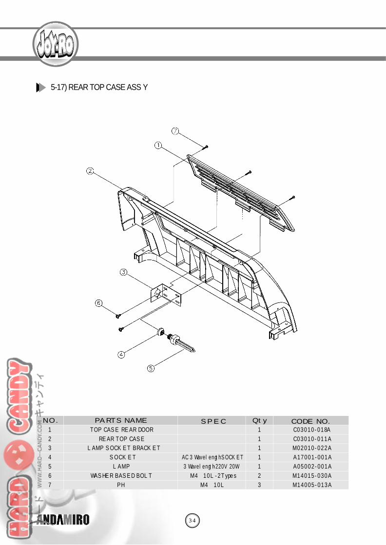
TOP CASE REAR DOOR
REAR TOP CASE
LAMP SOCKET BRACKET
S O C K E T
L A M P
WASHER BASED BOLT
P H
AC 3 Wavelength SOCKET
3 Wavelength-220V 20W
M 4×1 0 L - 2 T y p e s
M 4×1 0 L
S P E C Q t y. CODE NO.PA RTS NAMEN O .
1
2
3
4
5
6
7
1
1
1
1
1
2
3
5-17) REAR TOP CASE ASS’Y
36
C 0 3 0 1 0 - 0 1 3 A
C 0 3 0 1 0 - 0 1 4 A
C 0 3 0 1 0 - 0 2 4 A
C 0 3 0 1 0 - 0 2 5 A
C 0 3 0 1 0 - 0 1 5 A
C 0 3 0 1 0 - 0 1 6 A
M 1 4 0 0 6 - 0 4 2 A
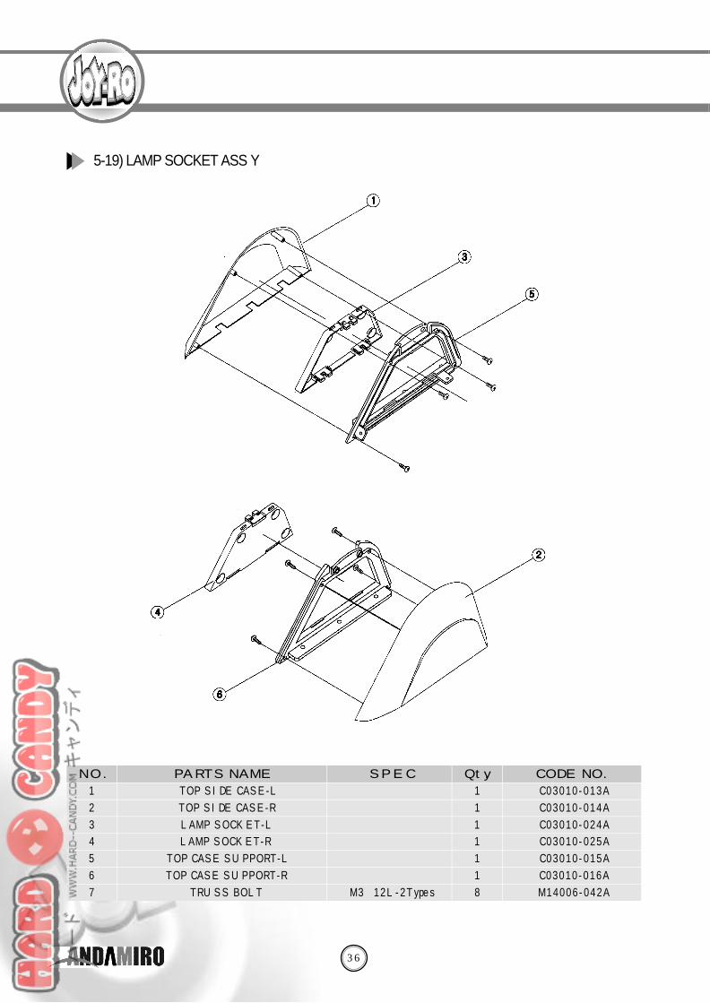
TOP SIDE CASE-L
TOP SIDE CASE-R
LAMP SOCKET-L
LAMP SOCKET-R
TOP CASE SUPPORT-L
TOP CASE SUPPORT-R
TRUSS BOLT M 3×1 2 L - 2 T y p e s
S P E C Q t y. CODE NO.PA RTS NAMEN O .
1
2
3
4
5
6
7
1
1
1
1
1
1
8
5-19) LAMP SOCKET ASS’Y
38
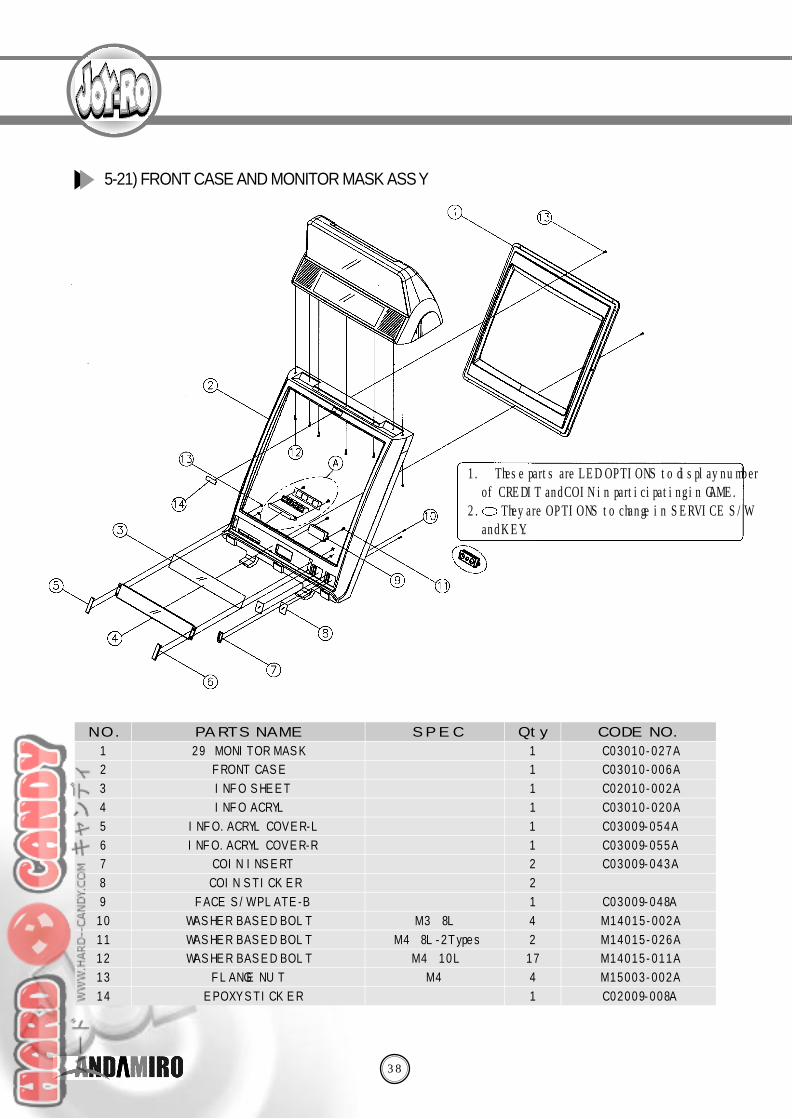
5-21) FRONT CASE AND MONITOR MASK ASS’Y
C 0 3 0 1 0 - 0 2 7 A
C 0 3 0 1 0 - 0 0 6 A
C 0 2 0 1 0 - 0 0 2 A
C 0 3 0 1 0 - 0 2 0 A
C 0 3 0 0 9 - 0 5 4 A
C 0 3 0 0 9 - 0 5 5 A
C 0 3 0 0 9 - 0 4 3 A
C 0 3 0 0 9 - 0 4 8 A
M 1 4 0 1 5 - 0 0 2 A
M 1 4 0 1 5 - 0 2 6 A
M 1 4 0 1 5 - 0 1 1 A
M 1 5 0 0 3 - 0 0 2 A
C 0 2 0 0 9 - 0 0 8 A
2 9”MONITOR MASK
FRONT CASE
INFO SHEET
INFO ACRYL
INFO.ACRYL COVER-L
INFO.ACRYL COVER-R
COIN INSERT
COIN STICKER
FACE S/W PLATE-B
WASHER BASED BOLT
WASHER BASED BOLT
WASHER BASED BOLT
FLANGE NUT
EPOXY STICKER
M 3×8 L
M 4×8 L - 2 T y p e s
M 4×1 0 L
M 4
S P E C Q t y. CODE NO.PA RTS NAMEN O .
1
2
3
4
5
6
7
8
9
1 0
1 1
1 2
1 3
1 4
1
1
1
1
1
1
2
2
1
4
2
1 7
4
1
1. ⒶThese parts are LED OPTIONS to display numberof CREDIT and COIN in participating in GAME.
2. They are OPTIONS to change in SERVICE S/Wand KEY.
40
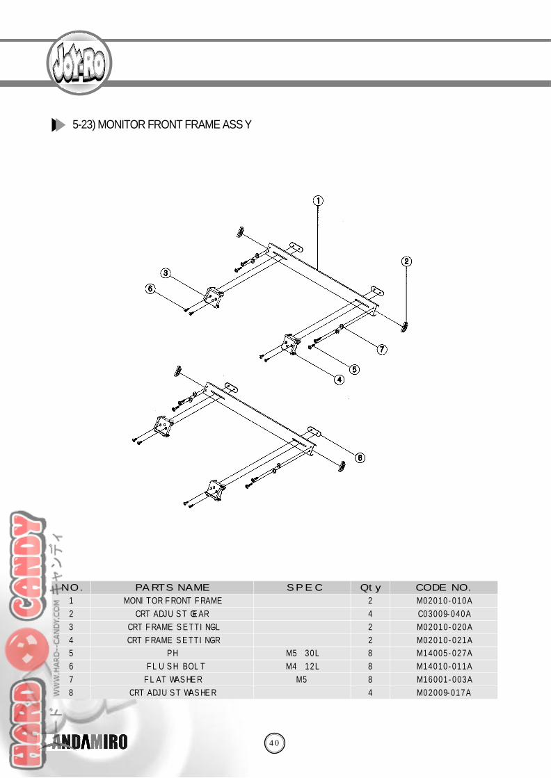
M 0 2 0 1 0 - 0 1 0 A
C 0 3 0 0 9 - 0 4 0 A
M 0 2 0 1 0 - 0 2 0 A
M 0 2 0 1 0 - 0 2 1 A
M 1 4 0 0 5 - 0 2 7 A
M 1 4 0 1 0 - 0 1 1 A
M 1 6 0 0 1 - 0 0 3 A
M 0 2 0 0 9 - 0 1 7 A
MONITOR FRONT FRAME
CRT ADJUST GEAR
CRT FRAME SETTING-L
CRT FRAME SETTING-R
P H
FLUSH BOLT
FLAT WASHER
CRT ADJUST WASHER
M 5×3 0 L
M 4×1 2 L
M 5
S P E C Q t y. CODE NO.PA RTS NAMEN O .
1
2
3
4
5
6
7
8
2
4
2
2
8
8
8
4
5-23) MONITOR FRONT FRAME ASS’Y
42
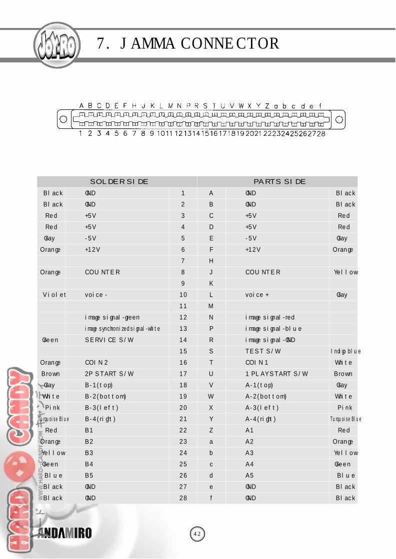
7. JAMMA CONNECTOR
SOLDER SIDE
B l a c k
B l a c k
R e d
R e d
G r a y
O r a n g e
O r a n g e
V i o l e t
G r e e n
O r a n g e
B r o w n
G r a y
W h i t e
P i n k
Turquoise Blue
R e d
O r a n g e
Y e l l o w
G r e e n
B l u e
B l a c k
B l a c k
1
2
3
4
5
6
7
8
9
1 0
1 1
1 2
1 3
1 4
1 5
1 6
1 7
1 8
1 9
2 0
2 1
2 2
2 3
2 4
2 5
2 6
2 7
2 8
A
B
C
D
E
F
H
J
K
L
M
N
P
R
S
T
U
V
W
X
Y
Z
a
b
c
d
e
f
B l a c k
B l a c k
R e d
R e d
G r a y
O r a n g e
Y e l l o w
G r a y
Indigo blue
W h i t e
B r o w n
G r a y
W h i t e
P i n k
Turquoise Blue
R e d
O r a n g e
Y e l l o w
G r e e n
B l u e
B l a c k
B l a c k
G N D
G N D
+ 5 V
+ 5 V
- 5 V
+ 1 2 V
C O U N T E R
voice “-”
image signal-green
image synchronized signal-white
SERVICE S/W
COIN 2
2P START S/W
B - 1 ( t o p )
B - 2 ( b o t t o m )
B - 3 ( l e f t )
B - 4 ( r i g h t )
B 1
B 2
B 3
B 4
B 5
G N D
G N D
G N D
G N D
+ 5 V
+ 5 V
- 5 V
+ 1 2 V
C O U N T E R
voice “+”
image signal-red
image signal-blue
image signal-GND
TEST S/W
COIN 1
1 PLAY START S/W
A - 1 ( t o p )
A - 2 ( b o t t o m )
A - 3 ( l e f t )
A - 4 ( r i g h t )
A 1
A 2
A 3
A 4
A 5
G N D
G N D
PA RTS SIDE
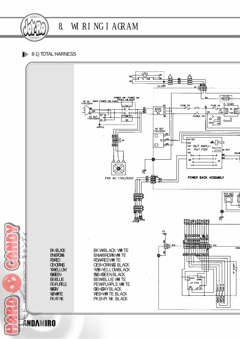
8. WIRING IAGRAM
8-1) TO TAL HARNESS
B K = B L A C K BKW=BLACK WHITEB N = B R O W N BNW=BROWN WHITER D = R E D RDW=RED WHITEO E = O R A N G E OEB=ORANGE BLACKY W = Y E L L O W YWB=YELLOW BLACKG N = G R E E N GNB=GREEN BLACKB E = B L U E BEW=BLUE WHITEP E = P U R P L E PEW=PURPLE WHITEG Y = G R A Y GYB=GRAY BLACKW E = W H I T E WEB=WHITE BLACKP K = P I N K PKB=PINK BLACK
45
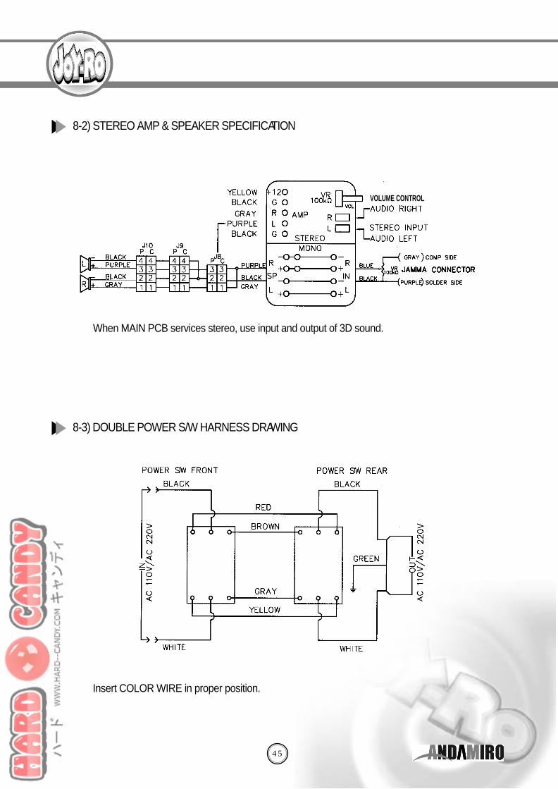
◎ When MAIN PCB services stereo, use input and output of 3D sound.
◎ Insert COLOR WIRE in proper position.
8-2) STEREO AMP & SPEAKER SPECIFICAT I O N
8-3) DOUBLE POWER S/W HARNESS DRAW I N G
VOLUME CONTROL
46
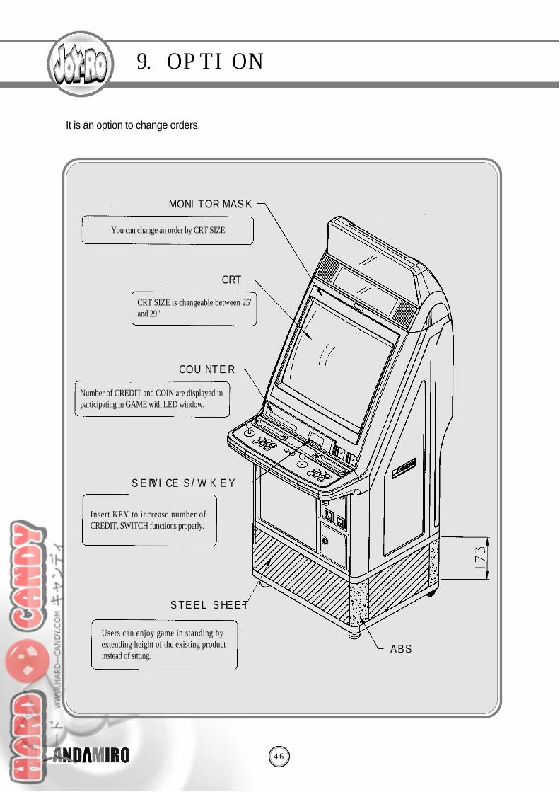
9. OPTION
MONITOR MASK
C RT
C O U N T E R
S E RVICE S/W및K E Y
STEEL SHEET
A B S
◎ It is an option to change orders.
CRT SIZE is changeable between 25"and 29."
Number of CREDIT and COIN are displayed inparticipating in GAME with LED window.
Insert KEY to increase number ofCREDIT, SWITCH functions properly.
Users can enjoy game in standing byextending height of the existing productinstead of sitting.
You can change an order by CRT SIZE.