precedi g i'.;ot f;li',ced lunar lander conceptual design · pdf file ·...
TRANSCRIPT

PRECEDI_G [L3_E .;3[e,".-_'.,,,_: I'.;OT F;Li',CED
LUNAR LANDER CONCEPTUAL DESIGN
119
J. M. Stecklein and A.J. petro
Mail Code ED231
NASAJohnson Space CenterHouston 77d 77058
W. R. Stump, A. S. Adorjan, T. V. Chambers,
M. D'Onofrio, J. 1_ _, O. G. Morris,
G. Nudd, R. P. Rawlings, C. C. Yarner,
C. W. YodzN, and S.J. Zlmprlch
Eagle Engineering16915 E1Camtno Real Suite 200Houston TX 77058
N93-17428
This paper is a first look at the problems of building a lunar lander to support a small lunar surfacebase. A series of trade studies was performed to define the lander. The initial trades concerned choosingnumber of stages, payload mass, parking orbit altitude, and propellant Ope. Other important tradesand issues included plane change capabik'ty, propellant loading and maintenance locatlog and rensa-bility considerations. Given a rough baseline, the systems ux,m then retqewed A conceptual dem'gn wasthen producecL The process was carried through only one iteration. Many more iterations am needecLA transportation system using reusable, aembmked orbital transfer vehicles (OTVs) is assumed TheseOTVs are assumed to be based and maintained at a low Earth orbit (LEO) _ace station, optimized
for transportation functions. Singl_ and two-stage OTV stacks are considered _ OTVs make thetranslunar injection (TLI), lunar orbit insertion (LOI), and trans-Eartb injection (1El) bums, as wellas midcourse and pen'gee raise maneuvers.
INTRODUCTION
This paper summarizes work carried out under NASA contract
and documented in more detail in the Lunar lander Conceptual
Design (Eagle Engineerln_ 1988). One lander, which can land
25,000 kg, one way, or take a 6000-kg crew capsule up and down
is proposed. The initial idea was to build a space-maintainable,
single-stage, reusable lander suitable for minimizing the
transportation cost to a permanent base, and use it from the first
manned mission on. Taking some penalty and perhaps expending
expensive vehicles early in the program would avoid building
multiple types of landers.
A single-stage lander is feasible from low lunar orbit (LLO) (less
than 1000 kin). The single-stage lander will be heavier (15-30%)
in LID than a two-stage vehicle. A lander capable of multiple roles,
such as landing cargo one way or taking crew modules round-
trip, is possible with some penalty (5-10%) over dedicated de-
signs; however, the size of payload delivered to lunar orbit may
vary by a factor of 2.
A four-engine design for a multipurpose vehicle, with total
thrust in the range of 35-40,0001bf (12,000 to 13,0001bf per
engine) and a throttling ratio in the 13:1 to 20:1 range is pro-
posed. Initial work indicates a regeneratively cooled, pump-fed
engine will be required due to difficulties with regenerative
cooling over wide throttling ranges with pressure-fed systems. The
engine is the single most important technical development item.
Reuse and space maintainability requirements make it near or
beyond the current state of the art. Study and simulation work
should continue until this engine is defined well enough for long
lead development to start.
The lander must be designed from the start for simplicity and
ease of maintenance. Design features such as special pressurized
volumes will be needed to make the vehicle maintainable in space.
Space maintainability and reusability must be made a priority.
Liquid oxygen/liquid hydrogen (LOX/LHz) propellants show
the best performance, but IM 2 may be difficult to store for long
periods in the lander on the surface. Earth-storable and space-
storable propellants are not ruled out. Liquid hydrogen storage
over a 180-day period on the lunar surface at the equator needs
study. A point design of a LOX/LH 2 lander needs to be done in
order to have a good inert mass data point that shows the
performance gain is real.
Initial calculations indicate LLO offers the lowest low-Earth-
orbit (LEO) stack mass. Low-altitude lunar orbits are unstable for
long periods. The instability limit may set the parking orbit al-titude.
Low-Earth-orbit basing for the lander is possible with some
penalty in LEO stack mass (10-25%) over a scheme that bases
the lander in LLO or expends it. The lander will require a special
orbital transfer vehicle (OTV) to aerobrake it into LEO, however.
Figure 1 shows a conceptual design of a LOX/LH 2 lander and a
large OTV that carries it, single stage, from LEO to LI.O and back
SCALING EQUATIONS
It is di_cult to accurately estimate the inert ma_ of the lander,
which is a key issue in several of the trades. An equation was
developed to scale the lander so that it matches the Apollo lunar
module (LM) at one point, and accounts for different payloads
and propellants. The LM provides the best historical data point
from which scaling equations can be formulated.
On a lunar lander some systems, such as overall structure, vary
with the gross or deorbit mass (Mg). Others, such as tanks, are
primarily dependent on propellant mass (M_). Other systems,

120 2nd Conference on Lunar Bases and Space Activities
Fig. 1. OTV and lander in lunar orbit.
such as the computers, will change very little or not at all with
the lander size. The inert mass (Mi), which is the sum of all of
these systems, can therefore be represented using equation ( 1)
Mi = CM_ + BMp + A (1)
To compare vehicles using cryogenic propellant systems with
vehicles using storable propellant systems, the equation needs
further modification. Due to the typically high volume associated
with cryogenic propellants, it is expected that the tank systems
and the thermal protection systems will be larger than for storable
propellants of the same mass. Equation (I) does not take sucheffec*,s into account.
One solution is to make the second term of the equation a
function of the propellant bulk density (Db). The bulk density is
the total mass of propellants divided by the total volume of
propellant. The tank inert mass is inversely related to the bulk
density, therefore the equation should be rewritten as
Mi = CMg + BMp/Db + A (Linear law) (2)
Mp/D b is the total volume of propellant. This equation is a linear
sealing function and assumes that those systems that are depend-
ent on the propellant, or bulk density, are scaled linearly with
propellant mass or volume.
The coefficients of the linear scaling law in equation (2) are
determined by matching the masses calculated from the law with
those of the Apollo LM for its various subsystems. The LM ascent
stage is taken as a model payload. The coefficients of the scaling
equation can be found and equation (2) becomes
Mi = 0.0640 Ms + 0.0506 (1168/Db) Mp + 390 <kg> (3)
Propellant Bulk Density Mixture Isp
lbm/ft 3 kgm/m 3 Ratio lbf-sec/lbm
N204/Aer 50 72.83 1168 1.6:1 300
N204/MMH 73.17 1170 1.9:1 330
LO2/LH 2 22.54 361 6:1 450
TWO-STAGE VS. SINGLE-STAGE
The LM true payload was calculated to be 2068 kg. A single-
stage vehicle, scaled using the above equation, transporting
2068 kg to and from the lunar surface to a 93-km circular orbit
must have a gross mass in orbit, prior to descent, of 21,824 kg.
When ascent and descent stages are used, applying the derived
,scaling equations, and assuming that the descent payload is equal
to the ascent gross mass, the total gross mass of the two-stage
lander prior to descent firom orbit is 18,903 kg. The real LM,
which is not an entirely equivalent case, had a mass of 16,285 kg.
As expected, single-stage to and from LLO results in some
penalty. This penalty must be weighed against the benefits of
single-stage operations, the chief one being easy reusability. Other

Stecklein et al.: Lunar lander conceptual design 121
benefits include reduced development cost and greater simplicity.
Total reusability is not practical without single-stage operation.
Once lunar surface oxygen becomes available, the performance
losses associated with single-stage operation will go away and
single-stage operation will be the preferred mode. Single-stage
operation is therefore chosen as the baseline.
SINGLE-STAGE PERFORMANCE PLOTS
Figures 2, 3, and 4 show the lander performance to and from
a 93-kin orbit using different propellants. The three propellants/
mixture ratios/Isps as shown in the above chart are used. The
Isps are chosen to be average values for a lunar ascent/descent.
Tile plots show three cases. In the "Cargo Down" case, the
lander does not have propellant to ascend to orbit after delivering
its payload. All the propellant capacity is used to deliver a large
payload to the surface. The case in which the lander places a
240
^
?
e_x:
ILI
4
i 1 1 I-,VIZT
J
8 12 16 20 24
(Thousands)
Payload Mass <kg>
Fig. 2. Single-stage crew/cargo lander. Orbit = 93 kin; MR = 1.6 N/A;
Isp = 300.
payload on the surface and has enough propellant remaining to
return its inert mass to orbit is called the "Inert Returned" case.
In the "Crew Module Round Trip" case a crew module is takendown to the surface and then back to orbit.
Tables 1 and 2 show performance vs. Isp as well as other
variables. The cryogenic vehicle shows better performance, but
not as much as expected. The low density of hydrogen drives the
propellant mass multiplier up in the scaling equation (3). The
equations may be biased against a pump-fed cryogenic system
because they are scaled from a pressure-fed storable system.
PARKING ORBIT ALTITUDE
Tables 1 and 2 show how lander mass increases steadily as lunar
orbital altitude goes up. Table 3 shows how LEO stack mass also
goes up with lunar orbit altitude. The LEO stack mass does not
rise dramatically until orbits of 1000 km or over are used. From
a performance standpoint, the lowest orbits are therefore
preferable. Apollo experience has indicated that very low orbits,
on the order of 100 kin, may be unstable over periods of months.
The best altitude will therefore be the lowest altitude that is stable
for the period required.
Ascent to a 93-km lunar orbit is assumed to be 1.85 km/sec.
Descent from a 93-km lunar orbit is assumed to be 2.10 km/sec.
These values were back-calculated from the Apollo 17 weight
statement in order to match design theoretical values. They
closely match postmission reported Apollo 11 AVs of 2.14 and
1.85 km/sec (Apo//o 11 Mission Report, 1969). Ascent/descent to
or from higher lunar orbits assumed a Hohmann transfer.
PLANE CHANGE CAPABILITY
One-time plane changes on the order of 15 ° in low lunarcircular orbit can be built in for modest lander maCs increases
on the order of 10% for LOX/LH 2 landers. This will also result
in a LEO stack mass increase of at least 10%. The plane change
AV and vehicle mass increase does not vary much with lunar orbit
altitudes below 1000km for a given angle of plane change;
_"°'i I 1 l L
150 i I J + _ _
I40 _ ---1 Cre_Modui_ Rom d 'hip
_ _ 90
5 _ ao
0 4 fl 12 16 20
_housands)
Payload _ass <ki>
- J I ' r i ! !/ _ '_° ' -' I -- i j ¢ .....
• - i i
! Crew Modulle Rou d
_ [
] t t t t t
24 0 4 8 IE 16
(Thousands)
Payload Mass <kg>
Trl I
/
/
i !
J _ l-j
/
/
/
20 24
Fig. 3. Single-stage crew/cargo lander. Orbit = 93 km; MR = 1.9 N/M; Fig. 4. Single-stage crew/cargo lander. Orbit = 93 km; MR = 6.0 O/H;
Isp = 330. Isp = 450.

122 2nd Conference on Lunar Bases and Space Activities
TABLE 1. lander rna_ _. altitude, 6000-kg crew module round trip.
Circ. Orbit Isp = 450 scc lsp = 330 sec
Altitude (kin) Deorbit Inert Propellant Deorbit Inert Propellant
Mass Mas,s Mass Mass Mass Mass
93 32 6 20 43 5 32
200 34 6 22 46 5 35400 37 7 24 50 6 38
1000 46 9 31 66 7 53
I-2 (M-LP-E) 166 13 147 344 38 300
TABLE 2. Lander mass w altitude, 25,000-kg cargo down case.
Circ. Orbit
Altitude (kin)
Isp= 450sec Isp= 330sec
_orbit Mert Prope_t _orbit Mert Prope_tM_ M_ M_ M_ M_ Ms
93 57 8 24 66 6 35200 58 8 25 68 7 36
400 60 8 27 70 7 381000 64 9 30 76 7 44
L2 (M-LP-E) 84 13 46 100 11 64
TABLE 3. LEO stack mass as a function of lunar orbit altitude.
I.LO Altitude Lander Deorbit LEO Stack Mass
(kin) Mass One-stage OTV Two-stage OTV
Load lander propellants in
LLO LEO LLO LEO
6_O._g crew _ round trip,uO-ZS-_O, dSO-sec IspLander
93 32 l 11 136
200 34 120 142
400 37 121 150
1,000 46 142 174
36,000(L2) 170 500 535
25,0&gkgcargo oneway, 45&seclspexpendedlander93 57 190 190
200 58 192 192
400 60 195 195
1,000 64 202 202
36,000 (L2) 84 268 268
6000&gcrewcapsulemundt_,LLO-LS-LLO, 33_seclsplander93 44 148 169
200 46 155 172
400 50 162 184
1,000 66 205 226
36,000(L2) 344 963 1,115
25,000-kgcargo one way, 33&seclsp_dlander93 66 217 217
200 68 221 221
400 70 229 229
1,000 75 238 238
36,000(L2) !00 314 314
101 127
107 133
112 140
131 165
471 506
174 174
176 176
180 180
187 187
246 246
137 159144 162
152 173
191 214
904 1,039
199 199204 2O4
208 208
219 219
290 29O
All _ are metric tons.All OTVs are LOX/LH2, 455-sec Isp.
Space station orbit altitude - 450 kin.Delta Vs as given in Table 4.Aft LEO-LLOtrajectories are 75-hr tra_,ffers.No plane changes are accounted for.OTVs are "rubber" and optimized to the given payload.OTVs assume: 15% of entry mass is aerobrake; 5% of prolxzllant is tankage, etc.; 2.3% of propellant is FPR and unusables.
Other OTV inerts = 2.5 m tons for two-stage, 4.5 m tons, for one-stage.
Stecklein et at.: Lunar lander conceptual design 123
however, as the orbit altitude increases above lO00km, plane
change AV goes down drastically, but the lander mass goes up
drastically due to increased ascent and descent AV (Table 4).
The ability to change planes widens the launch window the
vehicle has to reach high-inclination lunar orbit. For a landing site
such as Lacus Verus at 13°S latitude, it might allow a lander to
ascend to an OTV or LID space station in lunar equatorial orbit
at any time. This is a highly desired feature. For a high-latitude
base and parking orbit, polar for instance, a 15 ° plane change
capability would allow launch on roughly 4.5 days out of 27 days
in a lunar month.
TABLE 4. Delta Vs.
Lunar Orbit TLI LOI/TEI ° Total
93 3.101 0.846 3.947200 3.101 0.832 3.933400 3.102 0.809 3.910
1,000 3.102 0.759 3.86135,000 (L2, M-LP-E) 3.084 0.863 3.947
" LOI and TEl are assumed to be the same.
PROPELLANT LOADING _ONS
There are several options for lander propellant loading
locations. In addition to propellant loading, the lander must be
serviced with other consumables, maintained, and periodically
tested. Two straightforward options include (1)returning the
lander to the space station after each mission to the surface and
servicIng and loading it with propellants at the space station or
(2) loading the lander with propellants in lunar orbit and
servicing and maintaining it in lunar orbit.
The concept of maintenance and propellant transfer in space
is new. The space station will already have propellant loading,
maintenance, and refurbishment facilities for the OTVs. The space
station will have the largest stock of spares, most personnel,
shortest logistics tail, etc. Maintenance man-hours in space will
cost least at the space station. Development cost will be reduced
in that facilities required for the OTVs can be designed to servicethe landers as well.
Bringing the lander back requires a larger stack in LEO. Table 3
illustrates this. Given the OTV transportation system described,
bringing the lander back can cost as much as 25% more LEO mass
in one mission than loading propellants in lunar orbit. Loading
propellants in lunar orbit will also have costs however. The lander
will be left in a given orbit that the next mission must fly too.
Some performance loss or loss in mission flexibility will be
associated with this. If a facility is required in lunar orbit to handle
propellant transfer, then the flights needed to place and support
this facility represent a performance loss on the system.
It is difficult to integrate the lander with an aerobrake. An OTVspecially configured to carry the lander will be required, or the
lander will require its own aerobrake and will be an independentvehicle on return to Earth.
If it is practical to design a lander that can be loaded with
propellants and other consumables and be maintained and
checked out in lunar orbit without a fixed facility (a small lunar
orbit space station), then this is a more attractive option. There
is debate about the practicality of basing a reusable vehicle at the
space station however. The further away from Earth a vehicle is
based, the more expensive and difficult maintenance, repair, and
testing will become. Other performance losses would be
associated with operation from a fixed orbit. These losses will go
up as inclination of the lunar orbit goes up. If the base is
equatorial, this will not be a problem.
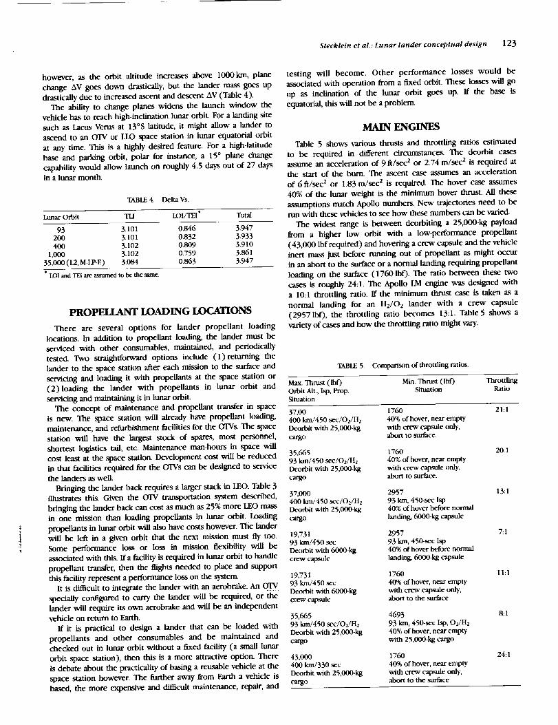
MAIN ENGINES
Table 5 shows various thrusts and throttling ratios estimated
to be required in different circumstances. The deorbit cases
assume an acceleration of 9 ft/sec 2 or 2.74 m/sec 2 is required at
the start of the burn. The ascent case assumes an acceleration
of 6 ft/sec 2 or 1.83 m/sec 2 is required. The hover case assumes
40% of the lunar weight is the minimum hover thrust. All these
assumptions match Apollo numbers. New trajectories need to be
run with these vehicles to see how these numbers can be varied.
The widest range is between deorbiting a 25,000-kg payload
from a higher low orbit with a low-performance propellant
(43,000 lbf required) and hovering a crew capsule and the vehicle
inert mass just before running out of propellant as might occur
in an abort to the surface or a normal landing requiring propellant
loading on the surface (1760 lb 0. The ratio between these two
cases is roughly 24:1. The Apollo LM engine was designed with
a 10:1 throttling ratio. If the minimum thrust case is taken as a
normal landing for an HJO2 lander with a crew capsule
(29571b0, the throttling ratio becomes 13:1. Table 5 shows a
variety of cases and how the throttling ratio might vary.
TABLE 5. Comparison of throttling ratios.
Max. Thrust (Ibf) Min. Thrust (lbf) ThrottlingOrbit Alt., Isp, Prop. Situation RatioSituation
37,00 1760 21:1
400 kin/450 sec/Oz/H2 40% of hover, near emptyDeorbit with 25,000-kg with crew capsule only,cargo abort to surface.
35,665 176093 kin/450 sec/O2/H2 40% of hover, near emptyDeorbit with 25,000-kg with crew capsule only,cargo abort to surface.
37,000400 kin/450 sec/Oz/H2
Deorbit with 25,000-kgcargo
19,73193 km/450 sec
Deorbit with 6000-kgcrew capsule
19,73193 kin/450 sec
Deorbit with 6000-kgcrew capsule
35,66593 km/450 sec/O2/H2
Deorbit with 25,000-kgcargo
43,000400 kin/330 sec
Deorbit with 25,000-kgcargo
2957
93 kin, 450-sec lsp40% of hover before normal
landing, (_00-kg capsule
2957
93 km, 450-sec Isp40% of hover before normal
landing, (_O0-kg capsule
1760
40% of hover, near emptywith crew capsule only,abort to the surface
469393 kin, 450-sec Isp, O2/H240% of hover, near empty
with 25,000-kg cargo
1760
40% of hover, near emptywith crew capsule only,abort to the surface
20:1
13:1
7:1
I1:1
8:1
24:1

124 2nd Conference on Lunar Bases and Space Activities
Reducing the required throttling ratio may have significant
advantages. The single, pressure-fed Apollo LM engine was cooled
by ablation of the nozzle. A reusable engine must be fegeneratively
cooled. Pressure-fed regenerative cooling over a wide throttling
ratio may not be possible due to the flow changing a great deal.
This leads to a pump-fed engine, a much more complicated
device, which then leads to two or more engines for redundancy.
A single-purpose lander, to land only a crew, might function with
a pressure-fed single engine. Table 5 indicates a throttling ratio
of 7 or 8 to 1 might be enough if one lander were not required
to bring down the 25,000-kg cargo and the crew capsule as well.
The table indicates that a dedicated cargo lander and a dedicated
crew lander would each require a throttling ratio of 7 or 8 to
1. The crew lander might use one or two engines and the cargo
lander four. Other schemes involving shutting off or not using
engines are also possible, but result in inert mass penaiiies.
Another option would be to reduce the lander deorbit acceler-
ation. The penalties for doing this should be determined_
On the other hand, pump-fed, cryogenic engines may be able
to function well in the 20:1 throttling ratio regime as some
individuals have claimed. Less work has been done on storable
engines with wide throttling ratios. The pump-fed engine may be
required even at low throttling ratios because of cooling
problems. The relationship between throttling ratio and engine
TABLE 6. Engine characteristics to be used for initial vehicle sizing.
O2/H2 N204/M_4I-I
Thrust (Ibf) 12,334Chamber Pressure (psia) 1,270Mixture Ratio (O/F) 6.0Max Isp (sec) 46OAve. 14:1 lsp (sec) 450Nozzle Area Ratio 620NozzIe Exit Diameter (in) 60
Engine Length (in) 115Weight (lb) 525
1.934033O
There are other propellant combinations to be investigated
such as O2/C3H 8 and O2/C2H4, which have higher performancethan N204/MMH; however, the propellant bulk densities are
lower. The combinations should be reviewed when the thrust
chamber cooling requirements and performance are investigated
for high throttling ratios. These propellants could take advantage
of surface-produced oxygen at some point in the future without
the problems of long-term hydrogen storage.
Pressure-fed propulsion systems with the Earth-storable
propellant combination N204/Aer50 were used for the Apollo
spacecraft propulsion systems for simplicity and reliability. The
cooling needs to be determined, in particular, the highest _ll0 d_ent--stage=_sichamber (nonre_ie)was:abhtively
throttling ratio, pressure-fed, regeneratively cooled engine, that cooled while the lunar lander thrust chamber (reusable) requires
will work, must be determined. If it is below 7 or 8, pressure-
fed engines can be eliminated as candidates.
Another possibility is a partially ablative engine. The combustion
chamber and throat could be regeneratively cooled and the
majority of the nozzle could be ablative, designed for easy
replacement every few missions, which might allow a pressure-
fed system to be used.
The Adaptable Space Propulsion System (ASPS) studies and the
OTV studies have narrowed the propellants to N204/MMH and
O2/H2, respectively, using pump-fed engine cycles. Some of the
technology efforts for the ASPS and OTV engines are underway
and more are planned. The lunar lander propulsion system can
benefit from this technology to a great extent. However, a
propulsion system designed especially for the lunar lander should
also be studied and compared to determine the technical
penalties of using the ASPS/OTV technology engines vs. the cost
and time penalties of developing another engine. Additional
technology requirements resulting fi'om the lunar lander studies
could be added to the ASPS/OTV engine technology programs.
This would decrease cost and development time for the lunar
lander engine program.
PROP_
There are many propellant combinations to consider for the
lunar lander study. For initial vehicle sizing the Earth-storable
combination NzO4/MMH and the cryogenic combination O2/H2
are selected (see Table 6). These propellant combinations are
being studied for other space propulsion systems and experience
has been gained by their use on operational spacecraft and
booster vehicles. All the previous tables and figures can be used
to compare the performance of these two propellants. In general,
the O2/H2 lander and LEO stack is 10-30% lighter. The OTVs are
all assumed to be O2/H2. More study of the inert mass is needed
to better qualify this difference, however. A point design of an
O2/H2 lander is needed to get good inert weights.
regenerative cooling. The estimated throttling for the lunar lander
cannot be achieved with a pressure-fed system using a regener-
atively cooled chamber and reasonable tank and system weights.
Therefore, the lunar lander will be pump-fed unless some
innovative method for thrust chamber cooling is discovered that
would then allow a pressure-fed vs. pump-fed comparison.
Achieving the required throttling and cooling with an Earth-
storable propellant, pump-fed propulsion system will also be
difficult and could prove unfeasible. The system would become
too complex if two engine designs (different maximum thrustlevels) and shutdown of engines became necessary to attain the
overall thrust variation.
NUMBER OF ENGINES
The complexity of a pump-fed engine requires at least two
engines for a manned space vehicle so that one engine failure will
not result in loss of crew. Vehicle control system requirements
and effective Isp must be considered in selecting the number of
engines, i.e., thrust vector control and loss of lsp due to
nonparallel engines if an engine fails.
Four engines have been tentatively selected for the initial study.
The engine size is smaller than a two- or three-engine configu-
ration and the throttling ratio is lower. The maximum thrust
required for the O2/H2 lunar lander configuration is assumed to
be 37,000 lb (see Table 5). For manned missions, if one engine
fails during hmar descent the mission will be aborted to lunar
orbit since redundancy would be lost for lunar launch. Thrust
would be adequate with two of the four engines operating, but
thrust vector control would be a problem. For unmanned
missions, if one engine fails during lunar descent, the mission will
be continued to lunar landing since there is no problem with loss
of crew, and at some point in the descent insufl]cient propellant
will be available to abort to lunar orbit. With these ground rules,
the selected maximum thrust level for each of the four engines
is 12,334 lb. This results in a total maximum thrust of 37,000 lb
in the event one engine fails during the unmanned lunar descent,

Stecklein et al.: Lunar lander conceptual design 125
and the lunar lander still has the capability to land, where a
normal landing determines minimum thrust on the lunar surface
as planned. The throttling ratio required per engine is 13.4:1. An
ascent/descent simulation with aborts is needed to refine these
numbers.
Another approach to obtain pump-fed engine redundancy is the
use of a single thrust chamber with two sets of turbopumps and
associated controls. This would result in a single thrust chamber
of 37,000-1b thrust with a slight gain in performance (higher area
ratio) and a simplification of the thrust vector control. Relying
on a single, reusable, regeneratively cooled thrust chamber with
the associated deterioration as missions are added would be one
reason to reject this approach. An extremely critical inspection
of this chamber would be required between missions ff this
engine system were selected.
The performance figures for NzO4/MMH are satisfactory for
preliminary vehicle sizing. Further information on engine cooling
is required before additional engine characteristics can be
determined. The use of a single, 37,000-1b-thrust/pump-fed engine
should be investigated since a large engine results in lower thrust
chamber cooling requirements. This investigation should include
the use of both propellants for thrust chamber cooling, the
integration of redundant turbopump operation, and the possible
requirement of a variable-area injector as used on the Apollo
descent engine to improve performance throughout the throttling
range.
The present technology goal for the OTV engine is an
operational life of 500 starts/20-hr burn time, and a service-free
life to 100 starts/4-hr burn time. Based on the Apollo LM burn
times this would allow approximately 58 operational missions and
11 service-free missions. This is a goal. The space shuttle main
engine (SSME) requires reservicing every mission and is effectively
replaced, on average, every three missions.
REACTION CONTROL SYSTEM (RCS)
The RCS propellants for the O2/H2 lunar lander are proposed
to be also OJH2 and are loaded into the main propellant tanks.
Liquid propellants are extracted from the main tanks, pumped to
a higher pressure, gasified by passing through a heat exchanger,
and then stored in accumulator tanks as gases to be used in gas/
gas RCS thrust chambers. The gas generators to operate the
turbopumps use gaseous oxygen/gaseous hydrogen and the
exhaust gases are passed through the heat exchanger to gasify the
LOX and LH 2 as mentioned previously. Sixteen thrusters are
located in four clusters 90 ° apart, four engines per cluster, to
supply the required control and translation thrust. The thrust of
each RCS engine is approximately 100 to 150 lb depending upon
vehicle requirements. The Isp is 370 sec, steady state.
The RCS propellants for the Earth-storable lunar lander are the
same as for the main engine, N20,i/MMH with separate RCS
propellant storage tanks and pressurization system. The engines
are pressure fed and the Isp is about 280 sec, steady state.
Integrating the N20_/MMH main propulsion system and the
RCS resulting in smaller RCS tanks and the elimination of the RCS
pressurization system is a possibility and warrants investigation.
SUPPORTABILITY
Support of the lander for an extended period of time will
require a different approach to all the supportability disciplines
than those that have been used for NASA manned spaceflight
programs through the space shuttle era. A new approach to
reusability, maintenance, and repairability considerations is
needed.
Technology available in the early 1990s can, in most cases,
produce sufficiently reliable hardware and software to support the
lunar lander scenario if proper management emphasis is given to
it. The space environment is, in many ways, quite benign and con-
ducive to long life and high reliability.Past NASA manned space programs, most notably Apollo and
space shuttle, have been initiated with the intent of providing in.
flight maintenance capability; however, these requirements were
either deleted from the program or not pursued with sufficient
rigor and dedication to provide meaningful results. It will be
necessary for the supportability requirements to be given
continuous high priority throughout the life cycle of the lander
if it is to achieve the current goals of space basing and long usefullife.
If true reusability with acceptable reliability is to be achieved,
these considerations must be given high priority from program
initiation onward. The current manned spacecraft redundancy
requirements will, in general, provide sufficient reliability for the
lander. To achieve high reliability it will be desirable to use proven
technology in as many of the vehicle systems as possible and still
meet the performance requirements. If the lunar lander is
adequately maintained and repaired then the reusability goal can
be met. The major exception may well occur in the main
propulsion system inasmuch as high-performance rocket engines
with life expectancies of the order needed to satisfy the lander
design requirements are not available.
Designing to achieve efficient space-based maintenance will give
rise to new problems and require unique approaches to keep
maintenance activity to an acceptable portion of the overall
manpower available. Teleoperated robotic technology is one
possibility. Another approach, shown in the conceptual design, is
a large pressurized volume on the lander that can be docked to
the space station and can be designed to hold most eqtdpment
requiring maintenance, servicIng, or replacement.
DATA MANAGFaMENT AND GUIDANCE,
NAVIGATION, AND CONTROL (GN&C)
The multipurpose lander must land with cargo unmanned as
well as manned. Sophisticated automatic fault detection,
identification, and reconfiguration (FDIR) will be required.
The vehicle must be designed from the onset to be entirely
self-checking and rely on onboard calibration. Most of the
maintainability functions specified for the space station are also
applicable to the lunar lander.
In addition, the lunar lander design must be capable of
autonomous launch. The Apollo program demonstrated many
aspects of the capabilities needed to launch and operate a vehicle
without the benefit of a costly launch check-out facility. With the
advances in expert system design and the increases in onboard
computer power the autonomous checkout goals should be
readily achievable but require that these functions are recognized
as primary requirements.
The data management system (DMS) is defined as the
redundant central processing system, multipurpose displays, data
bus network and general purpose multiplexor-demultiplexors.
The software system is also included. Although the DPS processors
accomplish the principal function processing, processors are

126 2nd Conference on Lunar Bases and Space Activitles
implemented at the subsystem or black box level to perform data
compression, FDIR functions, and other functions amenable to
local processing. These local processors would be procured to
be card compatible with the main processor. All items required
to interface with the standard data bus are procured with a built-
in data bus interface.
The DMS processor recommended is a 32-bit machine derived
from a commercial chip to capitalize on the advantages of off-
the-shelf software, support toolsl and the many other advantages
that accrue from having a readily available ground version of the
onboard machine. For the purpose of this conceptual design a
version of the Intel 80386 microprocessor was assumed.
Two multipurpose displays are proposed using flat screen
plasma technology. The operations management software supports
the monitoring of onboard consumables, system configurations,
and failure status, and displays this information for the benefit of
space station checkout crews or, when applicable, to the lunar
lander crew members. The display system also supports the flight
displays for _i0n phases when manual control is available.
The IMU proposed is a strapped down system based on ring-
laser gyro technology. This approach is chosen because Of advan-
tages in cost, ruggedness, stability, and ease of integrat!on with
optical alignment devices. Projected advances over the next few
years also show a clear advantage in weight and power over other
types of inertial systems. The ring-laser gyro is readily adaptable
to a "Hexad" configuration that provides the maximum redundan-
cy for the least weight and power. The "Hexad" configuration
contains a built-in triple redundant inertial sensor assembly (ISA)
processor that does the strapdown computations, sensor
calibration, redundancy management, checkout, and other local
processing assignments. The ISA processor also calculates the
vehicle attitude and vehicle body rates required for control system
stabilization.
Alignment of the IMU will be required prior to descent and
ascent to minimize errors and AV expenditure. This is accom-
plished by an automatic star scanner attached to the case of the
IMU to minimize boresight errors.
Guidance functions, control equations, jet select logic, and
similar processes are mechanized in the DMS processor. To the
maximum extent possible, these and other critical functions will
be implemented in read-only memory (ROM) to provide the
maximum reliability and lowest power and weight penalties.
Commands to the main engines and RCS engines are transmitted
via the triple-redundant data bus to the control electronics
sections where electrical voting takes place before transmittal of
the command to the actual effectors.
Automatic docking of the lunar lander with the OTV is a
requirement; however, the OTV is agsumed to be equipped withthe sensors and intelligence to accomplish this operation, and no
provision is made on the lunar lander to duplicate this capability.
Wherever the capability resides, it must be developed. The sensors
and software to do automatic docking do not exist at this time
in the free world.
A variety of systems are possible for updating the onboard
inertial system and performing landing navigation. The preferred
system is the cruise missile-type terrain-following radar with
surface-based transponders. The basic elements of this system will
all be part of the landers anyway, and depending on the surface
features and the knowledge of their positions, no surface elements
at all may be required. A small surface-based radar would be a
low-cost addition to the onboard terrain-following system.
The first requirement for terrain-following-type navigation is
knowledge of a terrain feature's location to within a certain range
of error. If the first landings on the site are manned, they must
occur during lighting conditions allowing good visual landing
navigation. The first landers can carry a transponder and, if
required, place another on the surface at a known location.
Subsequent landings will then get positions relative to thesewanslx)nder(s ). Table 7 estimates the mass, power, and volume
required for each component.
z
ENVIRONMFaVrAL CONTROL AND LIFE
sta'po SYSrF.MS(r.ClSS)Comparison of" open and Closed systems were made to
determine the crossover point where it pays to go from open loop
to a partially closed loop. The crossover point is dependent on
several factors: mass, volume, energy, and operational considera-
tions. From the mass standpoint, the crossover point was
approximately 60 days for the atmosphere revitalization system,
and 35 days for the water management system_ Neither of these
two comparisons took into account the impact on other
subsyste_ su_as power and the _ control. With the identified
power requirements, these impacts should be added to the ECLSS
mass impacts to arrive at a reasonable mass break-even point, As
a point of reference, a partially closed loop system is estimated
to require on the order of 4 kW of power and have hardware
masses of around 3000 kg. Open-loop systems are predicted to
require 1 kW of power and have a hardware rnass of 1300 kg for
15-day missions. The break-even point will be at an even longer
stay time when the additional power system mass required is
considered. Three- to 15-day missions are under consideration for
the lander. For these reasons, the system design selected was the
open-loop configuration (see Table 8).
The choice of power generation method can also bias the
choice of ECLSS design selection. If fuel cells are used to generate
electricity, then the process byproduct, water, can be used in the
open-l_p Concept. _ ::
The atmosphere supply and pressurization system source
consists of tanks of gaseous high-pressure nitrogen and oxygen.
If fuel cells are used for electrical power, then the system would
get oxygen from a common cryogenic supply tank. These sources
are fed through regulators to suplx)rt the cabin, crew suits,
airlock, and EMU station. Provisions are available for cabin and
airlock depressxtdzation and repressurization. Equalization valves
are available at each pressure volume interface. Partial pressure
sensors will be connected to the regulators to maintain the proper
atmosphere composition mix.
Atmosphere revitalization is supported by LiOH canisters for
CO2 removall _Ors _d particulates will be removed by activated
charcoal and filters. Cabin fans provide the necessary circulation
of the atmosphere through the system and habitable volume.
Humidity and temperature control will be handled by heat
exchangers and water separators. Thermal control for other
equipment in the crew compartment will be handled by cold
plates and a water loop connected to the thermal control system.
Included in this subsystem will be the fire detection and
suppression system.
Shuttle power requirements, itemized by systems that might be
comparable to lunar lander systems, were added up. The average
power required based on this calculation was 1.81 kW. The shuttle
is designed for a nominal crew of 7 with a contingency of 10.

Stecklein et al.: Lunar lander conceptual design 127
TABLE 7. DMS/GN&C mass and power.
Unit (Vehicle) Unit (Vehicle) Unit cubic ft
Component Weight (kg) Power (W) Volume (Config.) Number/Vehicle
DMS Processor 10 (30) 75 (225) 0.27 (0.81) 3MDM 7.7 (46.4) 60 (360) 0.25 (1.5) 6ANK/Display' 8.6 (17.3) 40 (80) 0.35 (0.7) 2Hexad IMU 16 (16) 75 (75) 0.3 (0.3) lStar Track 2 (6.1 ) 10 (30) 0.1 (0.3) 3Nay. Sensors
Landing 13.2 (13.2) 100 (100) 0.4 (0.4) 1Rendezvous 20.5 (20.5) 200 (200) 0.6 (0.6) 1
' ANK= alpha-numerlc keyboard.
Total Weight = 149.3 kg (325.5 Ib).Total Power: 1070_Total Volume = 0.13 cu m (4.61 cuft).
No. of SupportCrew Time (days)
TABLE 8. Open-loop ECLSS mass required.
Consumables Hardware Fluids(3 airlock (kg) (kg)
cycLv,)
Crew Prov.(+crew mass)
(M)
Total
(v,)
6 1 72 1264 214 2562 41124 3 133 1264 214 1708 33196 15 894 1264 214 2562 49344 15 612 1264 214 1708 3798
The lander crew module holds four with a contingency of six.
The power requirement is assumed to be roughly linear with crew
downsized by 4/7, resulting in a requirement for 1.0 kW average
power. Increased efficiency in motor design and advanced cooling
techniques occurring over the 20-30-year interval between the
two vehicles is expected to result in some savings as well.
ELECTRICAL POWER
Two scenarios have been discussed with respect to the crew
module. In one scenario the crew only enters the module todescend to the surface and lives in another module in-orbit. In
the second scenario, the crew lives in the lander module for the
complete trip, estimated to be 15 days minimum. For this reason
the lunar lander mission is broken down into two scenarios for
the electrical energy storage provisions: (1)Power up in lunar
orbit; descent, three days on surface; ascent to lunar orbit --
144 kWhr at 2 kW average. (2) Power up in LEO one day; three
days to lunar orbit; one day in ltmar orbit; descent, three days
on surface; ascent, one day in lunar orbit; three days to LEO; three
days in LEO -- 720 kWhr at 2 kW average ( 15 days).
The lander may stay much longer than three days on the
surface, but it is assumed that external power will be provided.
In either case it is assumed that the power system would be
serviced at the space station in LEO.
The 2-kW average power requirement is an estimate based on
the Apollo LM (peak power 2.3 kW) and calculations indicating
DMS/GN&C and ECLSS will each require about a kilowatt. This
may be reduced, but there will be other power requirements. A
more conservative estimate might be an average power require-ment of 3 kW.
Fuel cells and a number of ambient temperature batteries were
compared. The shuttle-derived fuel cell yields the system of lowest
weight and greatest flexibility. For large energy (>50kWhr)
requirements the fuel cell becomes the candidate of choice
primarily due to the large energy content of the reactants, H2 and
O2, supplying approximately 2200Whr/kg (tankage not in-
cluded). The reactant can be stored as a high-pressure gas, a liquid
in dedicated tanks, or the main propellant tanks can be used.
There is no impact from adding the fuel cell reactants to the
propellant tanks; 31 kg H2 adds 26 turn to the diameter of each
H2 tank, an increase of 0.7% for each parameter, and 244 kg O 2
adds 6 mm to the diameter of each 02 tank, an increase of 0.9%
and 0.3% respectively for each parameter. This provides energy
storage of 200% of that required for the 15May mission. Getting
the reactants out of the large tanks when only small quantities
are left may be a problem, however.
The fuel cell operating temperature range is between 80 ° and
95°C. It is provided with a fluid loop heat exchanger that is
integrated with the ECLSS thermal control loop, just as in the
shuttle orbiter. Heat rejection will be approximately 4400 btu/hr
at the 2-kW power level.
Fuel cell product water is portable and useful for crew
consumption and evaporative cooling. It is produced at the rate
of about 3/4 i/hr at the 2-kW power level for a total of 260 kg
for the 15-day mission. It is delivered to the fuel cell interface
in liquid form for transfer to the ECLSS system. Therefore, storage
and plumbing are not included in the power system design.
However, for single tank storage, a tank of 0.8 m in diameter is
required.
The baseline system used in the weight statements is a dual
redundant fuel cell system using dedicated tanks for cryogen
storage. Table 9 estimates the total mass of the system that

128 2nd Conference on Lunar Bases and Space Activities
TABLE 9. Fuel cell options.
H2/O2 Fuel Cells (100% redundancy, 15-day mission, 720 kWhr)
Energy Density (Whr/kg) System Weight (kg)
Dedicated Cryo Tanks 391 1842
Integrated with Propellant Tanks" 1051 685
" Added weight of proi_llant tanksfor slight increase in diameter not included. Reactants are included.
Fuel Cell System Analysis (no redundancy)"
Tank Tank EC. weight System weight Energy DensityReactants (kg) Diameter (m) Weight (kg) (kg) Fc,P,x,Tank (Whr/kg)
Gaseous
720 kWhr (15 days)H2 30.9 1.57 44202 243.7 1.46 215
68 1000 720
144 kWhr (3 days)H2 6.2 0.92 8802 48.8 0.73 43
68 254 567
Cryo720 kWhr ( 15 days)
H2 30.9 0.94 22402 243.7 0.74 354
68 921 782
144 kWhr (3 days)H2 6.2 0.55 45Oz 48.8 0.43 71
68 239 603
" 1 fuel cell, 1 set of tanks.
Included in weights: 1096fuel cell weight for mounting; 10%tankweight for plumbing/mountin_ 5%reactant weight for ullage.
provides 2 kW for 3 days as 478 kg. An equivalent system that uses
the main propellant tanks for reactants might weigh 274 kg (dual
redundant, not counting tank mass increase).
MULTIPURPOSE LANDER WEIGHT
STATEMENTS
Table 10 shows a multipurpose lander weight statement. The
cargo landing task results in the largest deorbit mass that scales
the structures, engines, RCS dry mass, and landing systems. The
round trip with a crew module results in the largest propellant
mass that scales the tanks and thermal protection. The electrical
power system uses four dedicated tanks for redundant reactant
storage. The AV includes an additional 0.43km/sec for a 15 °
plane change.
The multipurpose lander pays a penalty of 2300kg (lunar
deorbit mass) in the crew module case for being able to do all
three tasks, as compared to a lander designed to do only a round
trip with a crew module. The scaling equation described previ-
ously was used to determine these masses.
The plots shown in Figs. 2, 3, and 4 and tabulated in Tables 1,
2, and 3 are for similar landers, except the 0.43 km/sec AV for
plane change is not included and no mass for the airlock/tunnel
is included. They are therefore smaller, landers. Table 11 shows
the same lander sized for N204/MMH propellants.
LH2/LOX MULTIPURPOSE LANDER
CONCEPTUAL DESIGN
Figures 5 and 6 show a conceptual design of an LH2/LOX
multipurpose lander. The tanks are sized to hold roughly 30,000
kg total of propellant. The H2 tanks are 3.9 m in diameter, and
the 02 tanks are 2.76 m in diameter. The weight statement for
this lander is given in Table 10.
Important features of this lander include (1)airlc_k/servicing
tunnel down the center of the lander to allow _-y access on the
surface, and pressurized volume for LRUs, inside which many
engine connections can be made and broken; (2) flyable without
the crew module, which is removable; (3)fits in 30" heavy-lift
vehicle shroud with landing gear stowed; (4) electromechanical
shock absorbers on landing gear; and (5) emergency ascent with
one or two crew possible without crew module (crew would ride
in suits in airlock/servicing tunnel). Figure 7 shows this lander
being serviced on the lunar surface and illustrates how the
airlock/servicing tunnel allows pressurized access to a surface
vehicle. An engine is being removed in the figure.
Figure 1 shows this lander in lunar orbit, about to dock with
a large (single-stage) OTV.. The OTV is designed to return the
lander to the space station for servicing The OTV delivers the
lander to LLO, single stage, and waits in orbit for it to return.
The OTV tanks are sized to hold 118,000 kg of LOX/LH2 pro-
pellants.

TABLE 10. LO2/LH2 multipurpose lander weight statement.
Delta V, Ascent 0 2.28 * 2.28*
Paytoad, Ascent 0 6,000 O, Inert Massreturned to LLO
Delta ¥, Descent 2.10 2.10 2.10
Payload, Descent 25,000 6,000 14,000
Total Inert Mass 9,823 9,823 9,823
Structure 1,681 1,681 1,681
Engines 822 822 822RCS Dry 411 411 411
Landing System 784 784 784
Thermal Protection 2,0 i 7 2,0 i 7 2,017
Tanks 3,025 3,025 3,025
DMS (GN&C) 150 150 150Electr/cal Power * 478 478 478
Airlock/Tunnel 455 455 455
Total Propellant Mass 25,251 32,395 30,638
Ascent Propellant 0 I 1,334 7,240
Descent Propellant 22,597 18,137 20,486
Unusable Propelkant (3%) 678 884 832
FPR Propellant (4%) 904 1,179 1,109Usable RCS 858 689 778
Unusable RCS (5%) 43 34 39
FPR (20%) 172 138 156
Deorbit or Gross 35,074 42,218 40,461
Mass (less paytoad)Deorbit or Gross 60,074 48,218 54,461
' Delta V = i .85 + 0.43 km/sec for a 15 ° plane change in a 93-kin circular orbit.* Electrical power provided for three days only (2 kW). 100% redundant fuel cells
have dedicated reOuoda_t tankage.
All masses are kgo all AVs, km/sec, lsp = 450 (Ibf- sec/Ibm).
Steckletn et al.: Lunar lander conceptual design ] 29
TABLE 11. NzO4/MMH multipurpose landers.
Delta V, Ascent 0 2.28 ' 2.28 '
Payload, Ascent 0 6,000 O, Inert massreturned to LID
Delta V, Descent 2.10 2.10 2.10
Payload, Descent 25,000 6,000 14,000
Total Inert Mass 7,899 7,899 7,899
Structure 1,955 1,955 1,955
Engines 956 956 956
RCS Dry 478 478 478
Landing System 912 912 912Thermal Protection 1,006 1,006 1,006
Tanks 1,509 1,509 1,509
DMS/GN&C 150 150 150Electrical Power t 478 478 478
Airlock/Tunnel 455 455 455
Total Propellant Mass 36,398 50,767 45A29
Ascent Propellant 0 15,702 9,406
Descent Propellant 32,861 30,665 31,927
Unusable PropelLant 986 1,391 1,240
FPR Propellant (4%) 1,314 1,855 1,653Usable RCS 990 923 961Unusable RCS 50 46 48
FPR RCS (20%) 198 185 192
Deorbit or Gross
Mass (less payload) 44,297 58,666 53,328Deorbit or Gross 69,297 64,666 67,328
"Delta V= !.85 * 0.43 km/sec for a 15 ° plane change in a 93-kin circular orbit.• Electrical power provided for three days only (2 kW). 100% redundant fuel cells/rank sets.
All _ are kg, all A Vs, km/sec, lsp = 330 (lbf- sec/Ibm).
TUNNEL 14" --
INDENTED I _
TANK 'tI
( TYP 2PLCS) ! ._r'T"."."."."_t _ 6 PERSON\ "NNEOTHERMAL ___l_]llll ] II l[ II [ lltllllltlJlllL_MiCROMETEROID_ , , ,-\
4 "ridRO't-rL EBLE
LO2/LH2
ENGINES SCALE: 1/2" = 1 METER
v" 30' I.D. HLLV
PAYLOAD ENVELOPE
)
Fig, 5. LOX/LH2 reusable lunar lander, side view. Fig. 6. LOX/LH2 reusable lunar lander, top view.

130 2nd Conference on Lunar Bases and Space Activities
Fig. 7. Iander on surface.
- t4"_
6 PERSON
MANNED
MODI.N.E
Fx
Fig. 8. Lander on surface at pole.
I
=
=
!
_1
|
Fig. 9. Advanced storable reusable lunar lander, side view. Fig. 10. Advanced storable reusable lunar lander, top view.
Figure 8 shows the lander on the surface at the poles. The
lander may also serve as a suborbital "hopper" if propellant
loading on the lunar surface is provided. The figure illustrates
normal egress, without a pressurized vehicle.
ADVANCED STORABLE MULTIPURI_SE
LANDER CONCEPTUAL DESIGN
Figures 9 and 10 show a lander with equivalent capability to
the LOX/LH2 lander, except using NzO4/MMH propellants. This
lander, though considerably heavier than the IM2/LOX lander, is
much smaller, due to higher propellant density. Its features are
essentially the same as the previously described lander.
The propellant capacity of this lander is 35,000 kg divided into
four tanks of 16 cu m each. Tank diameter is 2.5 m for all tanks.
COST
Lander production costs were determined using a cost
estimating relationship (CER) model. With this method, design
and fabrication cost curves are developed for each vehicle
component, relating the component's historical costs to its
weight. Components from the Gemini, Apollo, Skylab, and shuttle
programs were considered when developing the CERs. Where
several significantly distinct classes of a given component existed,
a separate CER was created for each class. The cost curves
generated using this method usually had a correlation coeflScient
of 0.9 or better. All costs have been adjusted for inflation, and
are expressed in 1988 dollars. Program management wrap factorsare included in the CERs.

$tecklein et al.: Lunar lander conceptual design 131
Total design and development cost is estimated to be $1539
million, and total fabrication cost is estimated to be $759 million
per vehicle. Total program cost for ten vehicles is $9129 million.
To verify the reasonableness of these estimates, they were
compared to actual Apollo LM engineering and fabrication costs.
Estimated design and development costs were within 7% of actual
LM costs (when adjusted for inflation), and estimated fabrication
costs were within 2% of actual LM costs.
Design/Development Costs
Apollo LM (1967 SM)" 378
Apollo LM (adj. to 1988 SM) 1672New hmar lander ( 1988 SM) 1539
Fabrication Costs
Apollo LM (8 units, 1967 SM) 1354
Apollo LM (1 unit, 1967 SM) 169
Apollo LM (1 unit, adj. to 1988 SM) 745New lunar Lander ( 1 unit, 1988 SM) 759
"These numbers come from a 1967 document (Grumman Corp.,
1967). Other significant development costs were incurred after1967 that are not shown here.
REFERENCES
Apollo 11 Mission Report, MSC-O0171. Manned Spacecraft Center,
Houston, pp. 7-11.
Eagle Engineering (1988) Lunar Lander Concq0tua/Design, Report No.88-181, NASA Contract No. NASg-17878.
Grumman Corp. (1967) Lunar Modtae Program Cost Summary -- Total
Program.