predicting aeroelastic loads and response of healthy...
TRANSCRIPT

Predicting Aeroelastic Loads and Response of Healthy and Damaged
HAWT Blades
Heather Sauder
10/18/2013

Education:
Ph.D. in progress in Engineering Mechanics and Wind Energy Science, Engineering and Policy
M.S. in Mechanical Engineering from the University of Wyoming Dec 2012
DOE Workforce Training Fellowship in Wind Energy
B.S. in Physics and Spanish from Furman University 2011
Research:
Project sponsored by the Iowa Energy Center – Smart Sensory Membrane for Wind Turbine Blades
Developing a cost-effective Structural Health Monitoring (SHM) solution
Project PI – Simon Laflamme (Assistant Professor CCEE)
Interdepartmental project between CCEE, AerE, and ECpE
Personal Background
The primary objective of this research is to develop a better understanding of the aeroelastic loads and response of healthy and damaged wind turbine blades in varying wind conditions (i.e. smooth flow, turbulent flow, gusty winds, boundary layer, and yaw misalignment).
Objective
Self-excited
Buffeting
Vortex-Shedding Induced
Dynamic Wind Loads
Self-excited
Buffeting
Vortex-Shedding Induced
Dynamic Wind Loads
Motions of structures perturb the flow Modified flow patterns produce additional aerodynamic
stiffness and damping
Transfer energy from wind to motion of structure or help is dissipating kinetic energy of the structure.
Flutter speed Above a certain wind speed the kinetic energy of the
structure will no longer be dissipated and it will become dynamically unstable. This wind speed is known as the flutter speed.
Self-excited Wind Loads
𝐿𝑠𝑒 =1
2𝜌𝑈2𝐵 𝐾𝐻1
∗ℎ
𝑈+ 𝐾𝐻2
∗𝐵𝛼
𝑈+ 𝐾2𝐻3
∗𝛼 + 𝐾2𝐻4∗ℎ
𝐵
𝐷𝑠𝑒 =1
2𝜌𝑈2𝐵 𝐾𝑃5
∗ ℎ
𝑈+ 𝐾𝑃1
∗𝐵𝑝
𝑈+ 𝐾2𝑃4
∗𝑝 + 𝐾2𝑃6∗ℎ
𝐵
𝑀𝑠𝑒 =1
2𝜌𝑈2𝐵2 𝐾𝐴1
∗ℎ
𝑈+ 𝐾𝐴2
∗𝐵𝛼
𝑈+ 𝐾2𝐴3
∗𝛼 + 𝐾2𝐴4∗ℎ
𝐵
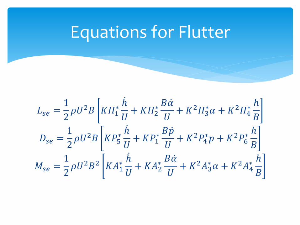
Equations for Flutter

𝐿𝑠𝑒 =1
2𝜌𝑈2𝐵 𝐾𝐻1
∗ℎ
𝑈+ 𝐾𝐻2
∗𝐵𝛼
𝑈+ 𝐾2𝐻3
∗𝛼 + 𝐾2𝐻4∗ℎ
𝐵
𝐷𝑠𝑒 =1
2𝜌𝑈2𝐵 𝐾𝑃5
∗ ℎ
𝑈+ 𝐾𝑃1
∗𝐵𝑝
𝑈+ 𝐾2𝑃4
∗𝑝 + 𝐾2𝑃6∗ℎ
𝐵
𝑀𝑠𝑒 =1
2𝜌𝑈2𝐵2 𝐾𝐴1
∗ℎ
𝑈+ 𝐾𝐴2
∗𝐵𝛼
𝑈+ 𝐾2𝐴3
∗𝛼 + 𝐾2𝐴4∗ℎ
𝐵
Equations for Flutter

𝐿𝑠𝑒 =1
2𝜌𝑈2𝐵 𝐾𝐻1
∗ℎ
𝑈+ 𝐾𝐻2
∗𝐵𝛼
𝑈+ 𝐾2𝐻3
∗𝛼 + 𝐾2𝐻4∗ℎ
𝐵
𝐷𝑠𝑒 =1
2𝜌𝑈2𝐵 𝐾𝑃5
∗ ℎ
𝑈+ 𝐾𝑃1
∗𝐵𝑝
𝑈+ 𝐾2𝑃4
∗𝑝 + 𝐾2𝑃6∗ℎ
𝐵
𝑀𝑠𝑒 =1
2𝜌𝑈2𝐵2 𝐾𝐴1
∗ℎ
𝑈+ 𝐾𝐴2
∗𝐵𝛼
𝑈+ 𝐾2𝐴3
∗𝛼 + 𝐾2𝐴4∗ℎ
𝐵
Equations for Flutter
Flutter Derivatives
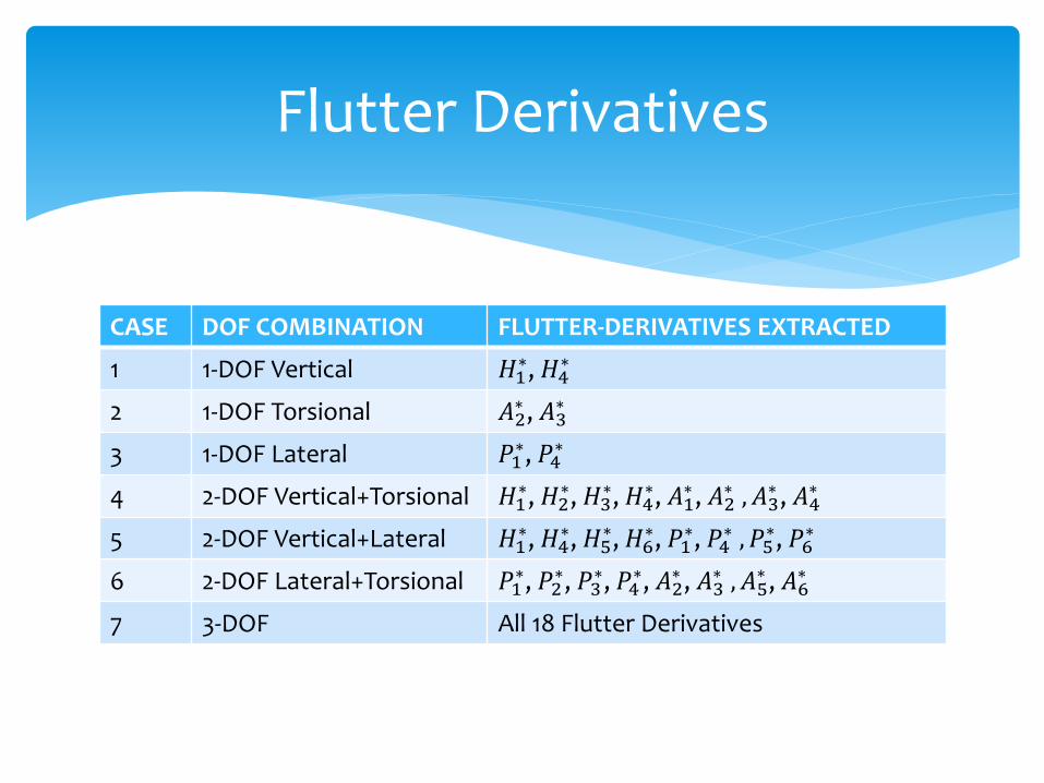
CASE DOF COMBINATION FLUTTER-DERIVATIVES EXTRACTED
1 1-DOF Vertical 𝐻1∗, 𝐻4
∗
2 1-DOF Torsional 𝐴2∗ , 𝐴3
∗
3 1-DOF Lateral 𝑃1∗, 𝑃4
∗
4 2-DOF Vertical+Torsional 𝐻1∗, 𝐻2
∗, 𝐻3∗, 𝐻4
∗, 𝐴1∗ , 𝐴2
∗ , 𝐴3∗ , 𝐴4
∗
5 2-DOF Vertical+Lateral 𝐻1∗, 𝐻4
∗, 𝐻5∗, 𝐻6
∗, 𝑃1∗, 𝑃4
∗ , 𝑃5∗, 𝑃6
∗
6 2-DOF Lateral+Torsional 𝑃1∗, 𝑃2
∗, 𝑃3∗, 𝑃4
∗, 𝐴2∗ , 𝐴3
∗ , 𝐴5∗ , 𝐴6
∗
7 3-DOF All 18 Flutter Derivatives
Flutter Derivatives
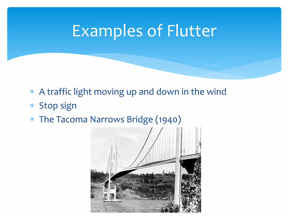
A traffic light moving up and down in the wind
Stop sign
The Tacoma Narrows Bridge (1940)
Examples of Flutter

http://www.youtube.com/watch?v=_oIYiFyyGC4
Flutter Video

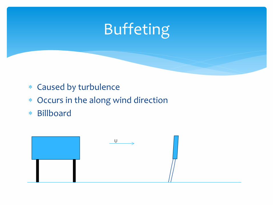
Caused by turbulence
Occurs in the along wind direction
Billboard
Buffeting
U
Caused by turbulence
Occurs in the along wind direction
Billboard
Buffeting
U
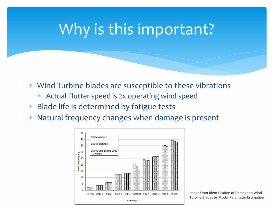
Wind Turbine blades are susceptible to these vibrations Actual Flutter speed is 2x operating wind speed
Blade life is determined by fatigue tests
Natural frequency changes when damage is present
Why is this important?
Image from Identification of Damage to Wind Turbine Blades by Modal Parameter Estimation

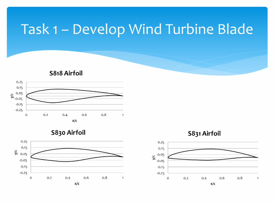
Task 1 – Develop Wind Turbine Blade
Task 2 – Section Model Testing
Task 3 – Finite Element Model
Task 4 – Wind Tunnel Tests
My Research Plan
Task 1 – Develop Wind Turbine Blade

Task 2 – Section Model Testing

Task 2 – Section Model Testing
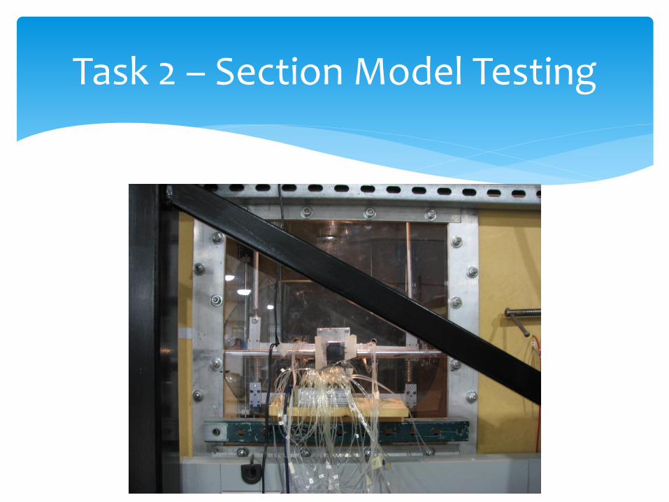
Task 2 – Section Model Testing
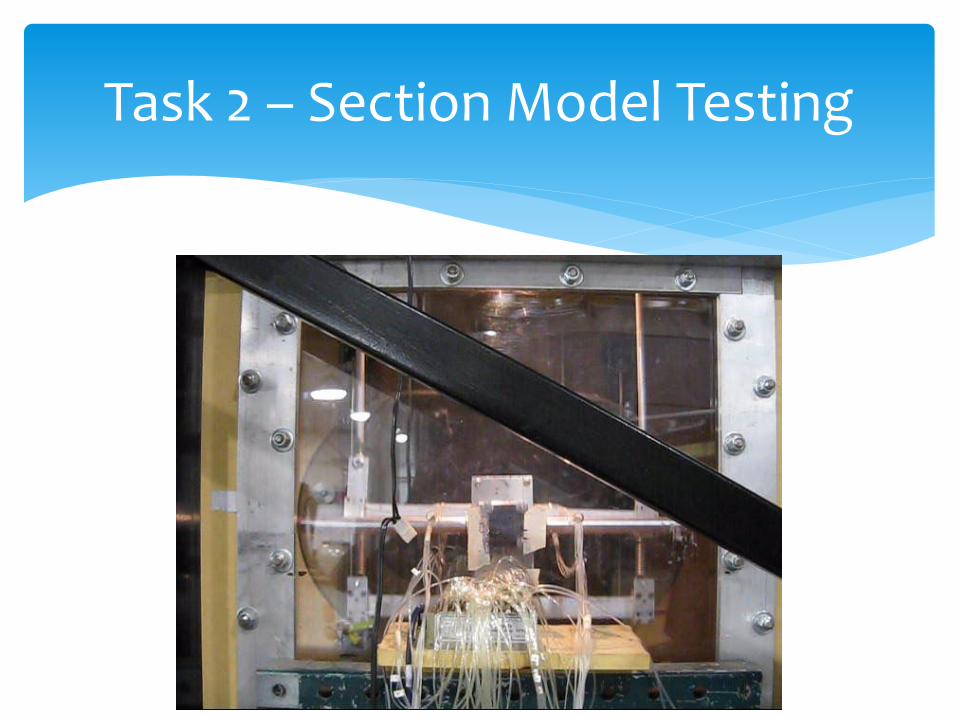
Task 2 – Section Model Testing
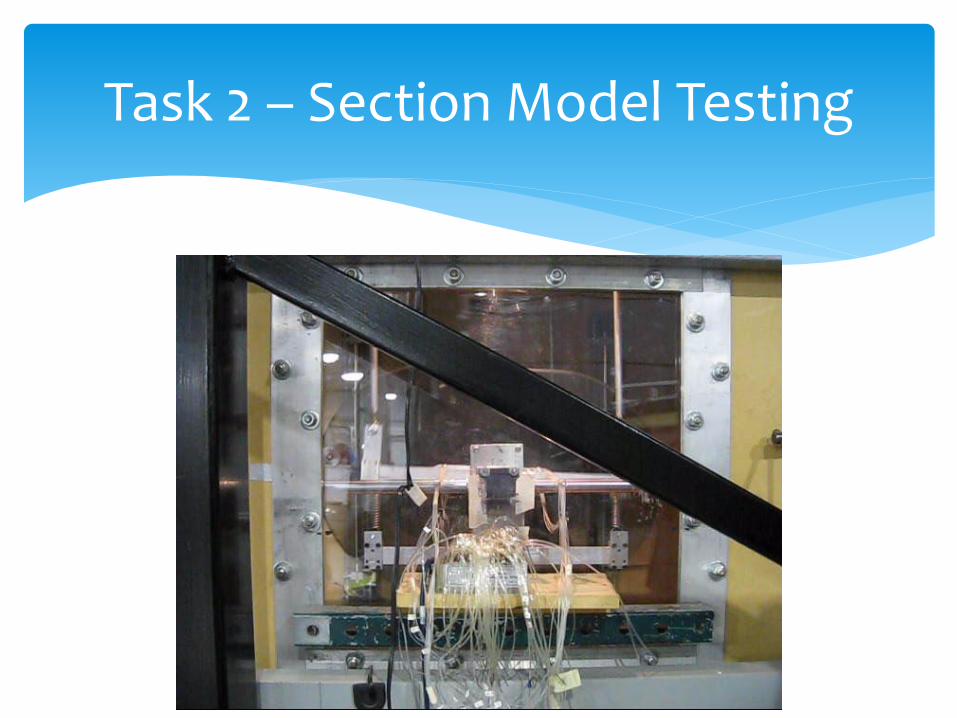
Task 2 – Section Model Testing
Used for a stress/response analysis of the prototype blade
Used to predict loads which can then be validated through pressure data taken
Task 3 – Finite Element Model
AABL Wind Tunnel (8ft x 6ft test section) 4ft long blade
Fixed at one end Free to vibrate on other end 1 Healthy & 4 damaged
Instrumented with: 1 Zoc33/ERAD Pressure Transducer 2 Accelerometers Conventional Strain Gauges Sensor Membrane Force/Torque sensor
Task 4 – Wind Tunnel Tests

Difference in loads and response from:
Gusts
Turbulence
Boundary Layer
Yaw Misalignment
Additional Work
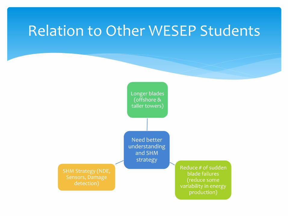
Relation to Other WESEP Students
Need better understanding
and SHM strategy
Longer blades (offshore &
taller towers)
Reduce # of sudden blade failures (reduce some
variability in energy production)
SHM Strategy (NDE, Sensors, Damage
detection)

Questions?

[1] Larsen GC, Hansen AM, Kistensen OJD. Identification of damage of wind turbine blades by model parameter estimation. Risø-R-1334;2002. [2] Kim B, Kim W, Lee S, Bae S, Lee Y. Development and verification of a performance based optimal design software for wind turbine blades. Renewable Energy 2013;54:166-172 [3] Xudong W, Shen WZ, Zhu WJ, Sørensen JN, Jin C. Shape Optimization of Wind Turbine blades. Wind Energy 2009;12:781-803. [4] Scanlan RH, Tomko JJ. Airfoil and bridge deck flutter derivatives. Journal of Engineering Mechanics 1971;97(6): 1717-1733. [5] Sarkar PP, Jones NP, Scanlan RH. Identification of aeroelastic parameters of flexible bridges. Journal of Engineering Mechanics 1994;120(8):1718-1742. [6] Gan Chowdhury A, Sarkar PP. A new technique for identification of eighteen flutter derivatives using a three-degree-of-freedom section model. Engineering Structures
2003;25(14):1763-1772. [7] Gan Chowdhury A, Sarkar PP. Experimental identification of rational function coefficients for time-domain flutter analysis. Engineering Structures 2005;27(9):1349-1364. [8] Sarkar PP, Gan Chowdhury A, Gardner TB. A novel elastic suspension system for wind tunnel section model studies. Journal of Wind Engineering and Industrial
Aerodynamics 2004;92(1):23-40. [9] Cao B, Sarkar PP. Identification of Rational Functions using two-degree-of-freedom model by forced vibration. Engineering Structures 2012;43:21-30. [10] Zhang Z, Chen Z, Cai Y, Ge Y. Indicial functions for bridge aeroelastic forces and time-domain flutter analysis. Journal of Bridge Engineering 2011;16:546-557. [11] Jeong MS, Kim SW, Lee I, Yoo SJ, Park KC. The impact of yaw error on aeroelastic characteristics of a horizontal axis wind turbine blade. Renewable Energy 2013;60:256-258. [12] Lobitz DW. Parameter Sensitivities Affecting the flutter Speed of a MW-Sized Blade. Journal of Solar Energy Engineering 2005;127:538-543. [13] Worasinchai S, Ingram G, Dominy R. A low-Reynolds-number, high-angle-of-attack investigation of wind turbine aerofoils. Journal of Power and Energy 2011;225:748-763. [14] Gonzalez A, Munduate X. Three-dimensional rotational aerodynamics on the NREL Phase VI wind turbine blade. Journal of Solar Energy Engineering 2008;130:1-7. [15] Baxevanou CA, Chaviaropoulos PK, Voutsinas SG, Vlachos NS. Evaluation study of a Navier-Stokes CFD aeroelastic model of wind turbine airfoils in classical flutter. [16] Bottasso CL, Cacciola S, Croce A. Estimation of blade structural properties from experimental data. Wind Energy 2013;16:501-518. [17] Mollineaux MG, Van Buren KL, Hemez FL, Atamturktur S. Simulating the dynamics of wind turbine blades: part I, model development and verification. Wind Energy
2013;16:694-710. [18] Cai X, Pan P, Zhu J, Gu R. The analysis of the aerodynamic character and structural response of large-scale wind turbine blades. Energies 2013;6:3134-3148. [19] Jeong MS, Lee I, Yoo SJ, Park KC. Torsional stiffness effects on the dynamic stability of a horizontal axis wind turbine blade. Energies 2013;6:2242-2261. [20] Lee JW, Lee JS, Han JH, Shin HK. Aeroelastic analysis of wind turbine blades based on modified strip theory. Journal of Wind Engineering and Industrial Aerodynamics
2012;110:62-69. [21] Lee YJ, Jhan YT, Chung CH. Fluid-structure interaction of FRP wind turbine blades under aerodynamic effect. Composites: Part B 2012;43:2180-2191. [22] Cao B, Sarkar PP. Time-domain aeroelastic loads and response of flexible bridges in gusty wind: prediction and experimental validation. Journal of Engineering Mechanics
2013;139(3):359-366. [23] Chang B, Sarkar P, Phares B. Time-domain model for predicting aerodynamic loads on a slender support structure for fatigue design. Journal of Engineering Mechanics
2010;136(6):736-746. [24] Maeda T, Ismaili E, Kawabuchi H, Kamada Y. Surface pressure distribution on a blade of a 10 m HAWT (Field measurements versus Wind tunnel measurements). Journal of
Solar Energy Engineering 2005;127:185-191. [25] Yang H, Shen WZ, Sørensen JN, Zhu WJ. Extraction of airfoil data using PIV and pressure measurements. Wind Energy 2011;14:539-556. [26] Amandolèse X, Széchényi E. Experimental study of the effect of turbulence on a section model blade oscillating in stall. Wind Energy 2004;7:267-282. [27] Sicot C, Devinant P, Loyer S, Hureau J. Rotational and turbulence effects on a wind turbine blade. Investigation of the stall mechanisms. Journal of Wind Engineering and
Industrial Aerodynamics 2008;96:1320-1331. [28] Micallef D, van Bussel G, Ferreira CS, Sant T. An investigation of radial velocities for a horizontal wind turbine in axial and yawed flows. Wind Energy 2013;16:529-544. [29] Haan FL, Kareem A. The effects of turbulence on the aerodynamics of oscillating prisms. ICWE12 CAIRNS 2007:1815-1822. [30] Ernst B, Seume JR. Investigation of site-specific wind field parameters and their effect on loads of offshore wind turbines. Energies 2012;2:3835-3855. [31] Lobitz DW. Aeroelastic Stability Predictions for a MW-sized blade. Wind Energy 2004;7:211-224. [32] Laflamme S, Saleem HS, Vasan BK, Geiger RL, Chen D, Kessler M, Bowler N, Rajan K. Soft elastomeric capacitor network for condition assessment of civil infrastructure.
IEEE Trans. on Mechatronics (under review)
References