prediction of eight ears in drawn cup based on a new ... of eight ears in drawn cup based on a new...
TRANSCRIPT

Prediction of Eight Ears in Drawn Cup Based on a New Anisotropic Yield Function
J.W. Yoon*, F. Barlat*, and R.E. Dick*, S. Choudhry**
* Alcoa Technical Center, 100 Technical Dr., Alcoa Center, PA 15069-0001, USA.
** Marc Development Group, MSC Software Corporation, 500 Arguello St., Redwood City, CA 94063, USA.
(Presentation number, 2004-59)
Abstract
A new yield function (Yld2004, Barlat et al. (2004): accepted for publication in Int. J. Plasticity) that well describes the anisotropic behavior of aluminum alloy sheets was implemented in MSC.Marc. A short review of the Yld2004 relevant features was provided and the formulation for the yield function implementation was proposed for its convenient use. Yield surface shapes, yield stress and r-value directionalities predicted with Yld20004 for AL 2090-T3 and FM8 sheet samples were compared with experimental data. Simulations of the cup drawing process for both materials were performed to show the cup height profile (earing profile). The simulation results were compared with experimental earing profile data and it was shown that the simulations using Yld2004 led to excellent predictions of the earing profiles for this aluminum alloy.
Keyword : Yield Function, Anisotropy, Earing, Finite Element Method, Aluminum
1. Introduction
In the automotive industry, significant efforts are being put forth to replace steel sheets with aluminum alloy sheets for automotive applications. Lighter in weight, aluminum sheets would improve the fuel efficiency of vehicles. However, besides higher material costs, there are several technical hurdles to overcome for a widespread usage of aluminum alloy sheets, such as lower formability and larger springback compared to steel sheets. Anisotropy has an important effect on the strain distribution in aluminum alloy sheet forming, and it is closely related to thinning and formability of sheet metals. Thus, the anisotropy of the material should be properly considered for the realistic analyses of aluminum sheet forming processes. The anisotropy of a sheet metal during sheet forming is a combination of the initial anisotropy due to its previous history of thermo-mechanical processing and to the plastic deformation during the stamping operation. The former leads to a symmetry with the orthotropic character while the latter, called deformation-induced anisotropy, can destroy this symmetry when principal material symmetry and deformation axes are not superimposed. Therefore, the modeling of plastic anisotropy itself and its implementation in finite element (FE) code can be complex. For practical purpose, the assumption that the change of anisotropic properties during sheet forming is small and negligible when compared to the anisotropy induced by rolling and heat treatment has been widely adopted in the analysis of sheet metal forming. This is particularly important for industrial applications, where user-friendliness and computation time are important factors to consider. In this case, it is convenient to use the concepts of anisotropic yield functions and isotropic hardening. Although this approach has its limitation (e.g., Tuğcu and Neale, 1999; Tuğcu et al., 2002), it has produced results in good agreements with experimental data (Worswick and Finn, 2000). For a more rigorous treatment, deformation-induced anisotropy, which is due to the evolution of the microstructure during forming, must be accounted for. Texture evolution, i.e., the rotation of individual grains, can be captured using polycrystal models (e.g., Inal, 2000; Peeters, 2001; Nakamachi, 2002). Note that the anisotropy due to the initial texture can be used without grain rotation. The dislocation accumulation and patterning in the material can be described by hardening rules that are based on the orientation distribution of the slip elements. In this sense, a phenomenological, dislocation-based approach for anisotropic hardening (Teodosiu and Hu, 1998) is valuable, especially when strain paths are not linear. The combination of crystal plasticity with anisotropic hardening rules can also be considered (Li et al., 2003). Finally, a sheet metal subjected to shear deformation looses its orthotropic character. Therefore, the lower symmetry exhibited by the material during forming is an element that should be captured as well. All the methods describing deformation-induced anisotropy are more appealing on a theoretical point of view. However, they can be difficult to implement or be used by sheet forming simulation experts who have usually a limited knowledge of material microstructure. Moreover, the data needed to capture deformation-induced anisotropy is rarely available, particularly for industrial applications. Finally, crystal plasticity using crystallographic texture input data leads only to an approximation of the observed material anisotropy. Therefore, when plastic deformation is moderate, like in sheet forming, a simple description of anisotropy based on experimental data as

input might be as accurate for sheet forming simulation than the more sophisticated anisotropy model, and at a much lower cost. For these reasons, a constitutive behavior based on an anisotropic yield function and isotropic hardening appears to be a reasonable choice for performing sheet forming simulations. Based on the isotropic hardening assumption there have been previous efforts to simulate anisotropic phenomena such as the formation of ears in drawing circular blanks. For this purpose, Gotoh and Ishise (1978) used Gotoh’s yield criterion for simulations on a mild steel. Yang and Kim (1986), and Doege and Seidal (1988) employed Hill’s 1948 original quadratic yield function (Hill, 1948) for a mild steel. Chung and Shah (1992), and Yoon et al. (1995) respectively applied the stress and the strain-rate potentials proposed by Barlat et al. (1991, 1993) for an 2008-T4 aluminum alloy sheet. Andersson et al. (1999) employed the criterion by Karafillis and Boyce (1993) for LDH test. Yoon et al. (2000a) used Yld96, the yield function suggested by Barlat et al. (1997) for circular deep drawing of a 2090-T3 aluminum alloy sheet. A new plane stress yield function, Yld2000-2d was recently proposed by Yoon et. al.(2000b) and Barlat et al. (2002) in details to alleviate the drawbacks of Yld96. Yld2000-2d was successfully implemented by Yoon et al. (2000b, 2004). Barlat et al.(2004) further suggested the new anisotropic model which takes into account more than four ears. The yield function requires the experimental input data every 15 degrees (if the data is available). Thus, it can capture the detailed distributions of r-value and yield stress anisotropies completely. The objective of the current study is to assess the behaviors of Barlat’s (2004) yield function (called Yld2004 below) in finite elements (FE) simulations of sheet metal forming processes. In the first section of this paper, the new anisotropic yield conditions are briefly summarized and discussed. The second section shows the examples of the anisotropic behaviors of aluminum sheet samples which are characterized with Yld2004. In the 3rd section, the FE formulation for the yield function and its implementation procedure are described. In this work, Yld2004 model is implemented to MSC.Marc. In the section of results and discussion, verification simulations were carried out. In order to observe the evolution of the cup height profiles (earing profiles) during forming, earing simulations were performed for Yld2004 solid model. These earing profiles were compared to experimental results obtained from a procedure, which was specially designed for this work.
2. Theory
2.1 Yield function
When a large number of experimental data are available, typically, uniaxial tension data for seven test directions between the rolling and transverse directions, as well as balanced biaxial data, the following analytical yield function denoted Yld2004 was proposed by Barlat et al.(2004) as

aaaa
aaa
aaa
SSSSSS
SSSSSS
SSSSSS
σ
φ
4~~~~~~
~~~~~~
~~~~~~)~,~(
''3
'3
''2
'3
''1
'3
''3
'2
''2
'2
''1
'2
''3
'1
''2
'1
''1
'1
'''
=−+−+−
+−+−+−
+−+−+−=SS
(1)
This is an isotropic and convex function with respect to its arguments. The two linear transformations provide 18 coefficients that can be used to capture the material anisotropy. When the coefficients are all equal to one, this function reduces to Hershey’s isotropic yield function (1954) proposed to reproduce the yield surface calculated with a self-consistent polycystal model. Recommended values of the exponent for this criterion are a=8 for FCC materials and a=6 for BCC materials. In Eq.1, '~
jS and "~kS are the principal values of S'~
and ''S~ (two linear transformations on the stress deviator) defined as
σσ LTCsCS ′=′=′=′~
~
σσ LTCsCS ′′=′′=′′=′′ (2) where
−−−−−−
=′
8
7
9
65
43
21
000000000000000000000000000
αα
ααα
αααα
C ,
−−−−−−
=′′
17
16
18
1514
1312
1110
000000000000000000000000000
αα
ααα
αααα
C
−−−−−−
=
300000030000003000000211000121000112
31T , .
=
zx
yz
xy
zz
yy
xx
σσσσσσ
σ

The principal values of s ′~ and s ′′~ , which define the diagonal tensor representation, are the roots of the characteristics equation
02~3~3~)~( 322
13 =′+′′+′′+′−=′ HSHSHSSP kkkk , (3a)
~~~~ 0233)( 322
13 =′′+′′′′+′′′′+′′−=′′ HSHSHSSP kkkk (3b)
where the associated 1st, 2nd and 3rd invariants of s ′~ and s ′′~ are
3/)~~~(1 zzyyxx sssH ′+′+′=′ , (4a) ~~~ 3/)(1 zzyyxx sssH ′′+′′+′′=′′ (4b)
3/)~~~~~~~~~( 222
2 zzxxzzyyyyxxzxyzxy sssssssssH ′′−′′−′′−′+′+′=′ (5a)
3/)~~~~~~~~~( 2222 zzxxzzyyyyxxzxyzxy sssssssssH ′′′′−′′′′−′′′′−′′+′′+′′=′′ (5b)
)~~~~~~~~~2~~~( 222
3 xyzzzxyyyzxxzxyzxyzzyyxx ssssssssssssH ′′−′′−′′−′′′+′′′=′ (6a) ~~~~~~~~~~~~ )2( 222
3 xyzzzxyyyzxxzxyzxyzzyyxx ssssssssssssH ′′′′−′′′′−′′′′−′′′′′′+′′′′′′=′′ . (6b) Note that when C , the formulation accounts for only one linear transformation. Yld2004 reduced to Yld91 (Barlat et al., 1991).
C ′′=′
In order to account for the rotation of anisotropy axes, a co-rotational coordinate system constructed at each integration point, which coincides with the planar anisotropy axis frame, was considered. In the present anisotropic theory, it is assumed that the orthogonality of anisotropic axes is preserved during sheet forming under isotropic assumption. In the polar decomposition theorem, the deformation of a material element (F) is decomposed into pure rotation, R and pure stretch, U (F=RU). The rotation of the anisotropy axes about the amount of rotation(R) is incrementally updated by MSC.Marc before Material model for stress integration is called.
2.2 Aluminum alloy sheet samples The material characteristics for two aluminum alloy sheet samples denoted AL2090-T3 and FM8, which were used for the earing profile simulations, were reviewed in this section. Duplicate uniaxial tension tests for every 15 degrees and hydraulic bulge test were conducted in order to measure the true stress-strain curves and the plastic strain ratios (r-values). The balanced biaxial true stress-strain data measured in the bulge test were fit to hardening of the materials. The input data for Yld2004 are given in Table 1.

Table 1. Yield function coefficients for AL2090-T3 and FM8 (exponent a= 8).
AL 2090-T3 FM8 1α -0.0698 10α 0.9811 1α 0.7297 10α 1.0513
2α 0.9364 11α 0.4767 2α 0.8777 11α 1.0389
3α 0.0791 12α 0.5753 3α 0.4252 12α 1.3289
4α 1.0030 13α 0.8668 4α 0.7268 13α 1.1775
5α 0.5247 14α 1.1450 5α 1.1386 14α 0.7651
6α 1.3631 15α -0.0792 6α 1.0000 15α 0.9169
7α 1.0237 16α 1.0516 7α 1.0000 16α 1.0000
8α 1.0690 17α 1.1471 8α 1.0000 17α 1.0000
9α 0.9543 18α 1.4046 9α 1.3485 18α 0.0432
Figure 1 shows the yield surface of both samples predicted with Yld2004. Figure 2 shows normalized yield stress and r-value anisotropies, predicted with the yield functions and determined experimentally. As shown in the figures, Yld2004 perfectly captures both yield stress and r-value anisotropies.
(a) (b)
Figure 1. Yield surface shapes: (a) AL2090-T3, (b) FM8

(a) (b)
Figure 2. Normalized yield stress r-value plots: (a) AL2090-T3, (b) FM8
2.3 Stress integration for elasto-plasticity with anisotropic yield function
Utilizing the normality rule, the associated plastic strain increment is obtained from the
effective stress
pαβε∆
σ as
αβαβ ∂σ
σ∂εε pp ∆=∆ (7)
where pε∆ is the equivalent plastic strain increment. In order to get the plastic strain increment, , the incremental deformation theory (Yoon et al (1999a,b)) was applied to the elasto-plastic
formulation based on the materially embedded coordinate system. Under this scheme, the strain increments in the flow formulation are the discrete true (or logarithmic) strain increments, and the material rotates by the incremental angle obtained from the polar decomposition at each discrete step.
pαβε∆
The numerical procedure to obtain is to find the unknown p
αβε∆ pε∆ (the equivalent plastic
strain increment) from nonlinear equations. Using pε∆ , all kinematics variables and stresses are updated at the end of every step. The nonlinear equations to solve for pε∆ and which enable the
resulting stresses to stay on the hardening curve ( )( pερρ = ), are
)()( Pnn εερσ ∆+=∆+ σσ (8a) where

)( pεεσ ∆−∆=∆ C (8b) and
σε
∂∂
∆=∆σε pp . (8c)
The incremental relationship of Eq.(8b) is expressed in co-rotational coordinate system in MSC.Marc. Therefore, Eq.(8b) is objective with respect to material rotation. Note that, in the incremental deformation theory, γε =∆ p ; i.e.,
γσσγ
σ
σγ
σε ==∂
∂
=∆
=∆)()(
)(
:
)(:
σσ
σσ
σ
σεσ p
p (9)
where σ is a first order homogenous function, that is σ
σσ∂∂
=σσ )( . The above equation is useful
when the effective stress does not have its conjugate effective strain explicitly defined with respect to Dp, as for Yld2004. The condition stipulating that the updated stress stays on the work-hardening curve provides the following equation:
0)(-)()( e =+−= Τ γεργσγ pnF mCσ (10a)
where
εσσ ∆+=Τ eCn and σ∂
∂=
σm . (10b)
Eq.(10b) is a nonlinear equation to solve for γ . The predictor-corrector scheme based on the Newton-Raphson method is generally used to solve Eq.(10a). However, if the strain increment is not small enough, it is difficult to obtain the solution of Eq.(10a) numerically, even though Eq.(10a) has a mathematical solution. In this work, a multi-stage return mapping procedure, which utilizes the control of the potential residual suggested by Yoon et al (1999a), was employed.
2.4 Consistent tangent modulus In order to find the algorithmic tangent, the following relationship is considered
0)(-)()( 1111 == ++++p
nnnnF ερσ σσ (11a) where
111 +++ −)−(+= ne
nne
nn mCC γεεσσ (11b)
Hpnn
pnn γερερ +=++ )()( 11 . (11c)
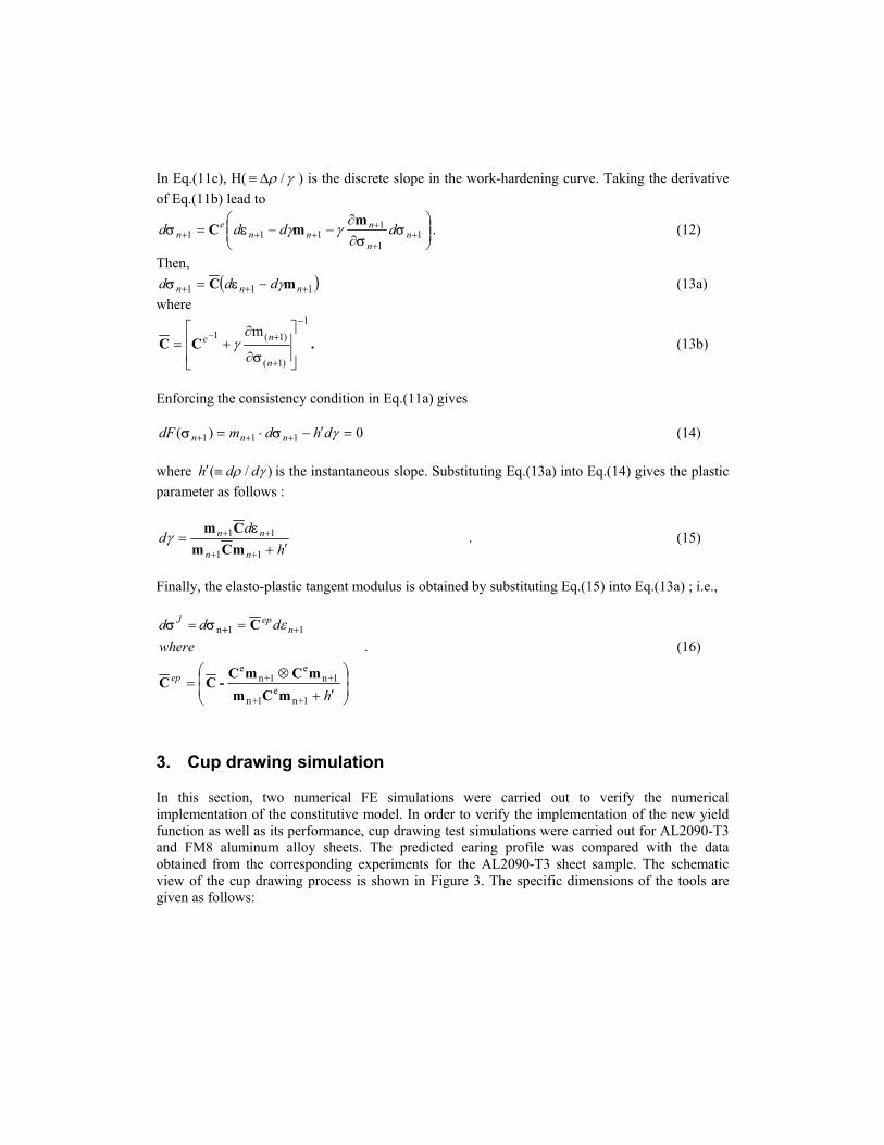
In Eq.(11c), H( γρ /∆≡ ) is the discrete slope in the work-hardening curve. Taking the derivative of Eq.(11b) lead to
∂∂
−−= ++
++++ 1
1
1111 n
n
nnn
en dddd σ
σεσ
mmC γγ . (12)
Then, ( 111 +++ −= nnn ddd mC γεσ ) (13a)
where 1
)1(
)1(1 m−
+
+−
∂
∂+=
n
ne
σγCC . (13b)
Enforcing the consistency condition in Eq.(11a) gives
0)( 111 =′−⋅= +++ γdhdmdF nnn σσ (14) where )/( γρ ddh ≡′ is the instantaneous slope. Substituting Eq.(13a) into Eq.(14) gives the plastic parameter as follows :
hd
dnn
nn
′+=
++
++
11
11
mCmCm ε
γ . (15)
Finally, the elasto-plastic tangent modulus is obtained by substituting Eq.(15) into Eq.(13a) ; i.e.,
′+
⊗=
== +
h
whereddd
ep
nepJ
1+ne
1+n
1+ne
1+ne
11n
mCmmCmC
-CC
C ε+σσ . (16)
3. Cup drawing simulation
In this section, two numerical FE simulations were carried out to verify the numerical implementation of the constitutive model. In order to verify the implementation of the new yield function as well as its performance, cup drawing test simulations were carried out for AL2090-T3 and FM8 aluminum alloy sheets. The predicted earing profile was compared with the data obtained from the corresponding experiments for the AL2090-T3 sheet sample. The schematic view of the cup drawing process is shown in Figure 3. The specific dimensions of the tools are given as follows:

Figure 3. Schematic view of mini-die drawing process.
Punch diameter : Dp = 97.46 mm Punch profile radius : rp = 12.70 mm Die opening diameter : Dd = 101.48 mm Die profile radius : rd = 12.70 mm Blank radius : Db = 158.76 mm
Only a quarter section of the cup was analyzed in light of the orthotropic material symmetry. The material and process variables used in the simulations are given below:
Stress-strain curve characteristics : σ ε (Mpa) = +646 0 025 0 227( . ) .
Initial sheet thickness : 1.6 mm Coulomb coefficient of friction : 0.1 Blank holding force : 22.2 kN
The cup drawing test is not only a material test but also a forming operation which accounts for the combined effects of friction, blank-holder force and sheet bending-unbending. In order to minimize the influence of the blank-holder force and friction in this verification, a cup formed with a minimum blank-holder force to prevent wrinkling under a well-lubricated condition was simulated, which correspond to the experimental conditions. The simulated cup height profile obtained from the value of BHF=22.2 kN (approximately 1 % of the yield force) and friction coefficient = 0.1 were compared with experimental results. Assuming isotropic hardening, the yield function coefficients were kept constant during the simulation.

(a) (b)
Figure 4. Deformed configurations of completely drawn cups using Yld2004 : (a) AL 2090-T3 (b) FM8
Figure 6. Comparison of earing profiles for AL 2090-T3
Fig.4 shows the deformed configurations of completely drawn cups of the aluminum alloy sheets. 2090-T3 alloy sheet is generally used for aerospace applications and exhibits severe anisotropy. It is observed that AL2090-T3 material shows six ears, while FM8 material shows eight ears. It is directly related to r-value distribution in Fig.2. The prediction of earing profile larger than four ears is the unique capability of Yld2004. In Fig.5, the measured and predicted cup height profiles are compared for AL 2090-T3 sheet. For an orthotropic material, the cup height profile between 0o and 90o should be the mirror image of the cup height profile between 90o and 180o with respect to

the 90o axis. However, the measured earing profile slightly deviates from this condition. This deviation might have occurred because the center of the blank was not aligned properly with the centers of the die and the punch during processing. Generally, this plot shows that the earing profile obtained from the present theory is in very good agreement with the measured profile. Especially, the results based on Yld2004 captures small ear around rolling direction and 180 degrees, which could not be predicted with the previously reported yield functions. It is worth to mention that r-value plots in Fig.5 and earing profile in Fig.2 show the mirror image.
4. Conclusion remarks
The yield stress and r-value directionalities obtained from a newly published yield function called Yld2004 were investigated for AL 2090-T3 and FM8 aluminum alloy sheet samples. The anisotropic properties for both materials were well captured by Yld2004. The new yield function was successfully implemented into MSC.Marc. A cup drawing test was performed for the two materials sheet in order to investigate the earing profile using Yld2004 and experimental results were found to be in good agreement especially for six and eight earing. This example validates both the ability of Yld2004 to capture anisotropic properties of aluminum alloy sheets and the successful implementation of this function into a FE code.
5. References
1. Andersson, A., Ohlsson, C.A, Mattiason, K., Persson, B., “Implementation and evalustion of the Karafillis-Boyce material model for anisotropic metal sheets”, Proceedings of NUMISHEET’99 Vol.1 edited by J.C. Gelin and P. Picart, Besancon, France, pp.115-121, 1999.
2. Barlat, F., Lege, D.J. and Brem, J.C., “A six-component yield function for anisoropic metals”, Int. J. Plasticity, 7, 693, 1991.
3. Barlat, F., Chung, K. and Richmond, O., “Strain rate potential for metals and its application to minimum plastic work path calculations”, Int. J. Plasticity, 9, 1, 1993.
4. Barlat, F., Becker, R.C., Hayashida, Y., Maeda, Y., Yanagawa, M., Chung, K., Brem, J.C., Lege, D.J., Matsui, K., Murtha, S.J., Hattori, S., “Yielding description of solution strengthened aluminum alloys”, Int. J. Plasticity, 13, 385, 1997.
5. Barlat, F., Maeda, Y., Chung, K., Yanagawa, M., Brem, J.C., Hayashida, Y., Lege, D.J., Matsui, K., Murtha, S.J., Hattori, S., Becker, R.C. and Makosey, S., “Yield function development for aluminum alloy sheet”, J. Mech. Phys. Solids, 45, 1727, 1997.
6. Barlat, F., Brem, J.C., Yoon, J.W., Chung, K., Dick, R.E., Choi, S.H., Pourboghrat, F., Chu, E., Lege, D.J., “Plane stress yield function for aluminum alloy sheets”, Int. J. Plasticity, 19, 1297, 2003.
7. Barlat, F., Aretz, H., Yoon, J.W., Karabin, M.E., Brem, J.C. and Dick, R.E., Linear transformation based anisotropic yield function, Int. J. Plasticity, 2004 (In Press).

8. Chung, K. and Shah, K., “Finite element simulation of sheet metal forming for planar anisotropic metals”, Int. J. Plasticity, 8, 453, 1992.
9. Doege, E. and Seydel, M., ”Influence of anisotropy in sheet metal forming in modeling of metal forming processes” (edited by J.L. Chenot and E. Onate), pp.123, Kluwer Academic Publishers, Rotterdam, The Netherlands, 1988.
10. Gotoh, M. and Ishise, F., “A finite element analysis of rigid-plastic deformation of the flange in a deep-drawing process based on a fourth-degree yield function”, Int. J. Mech. Sci., 20, 423, 1978.
11. Gotoh, M., “A finite element analysis of rigid-plastic deformation of the flange in a deep-drawing process based on a fourth-degree yield function-Part II”, Int. J. Mech. Sci., 20, 367, 1980.
12. Hill, R., “A theory of the yielding and plastic flow of anisotropic metals”, Proc. Roy. Soc. London, 193A, 281, 1948.
13. Inal, K., Wu, P.D., Neale, K.W., “Simulation of earing in textured aluminum sheets”, Int. J. Plasticity 16, 635, 2000.
14. Karafillis, A.P. and Boyce, M.C., “A general anisotropic yield criterion using bounds and a transformation weighting tensor”, J. Mech. Phys. Solids, 41, 1859, 1993.
15. Li, S., Hoferlin, E., Van Bael, A., Van Houtte, P., Teodosiu, C., “Finite element modeling of plastic anisotropy induced by texture and strain-path change”, Int. J. Plasticity 19, 647, 2003.
16. Nakamachi, E., Xie, C.L., Morimoto, H. Morita, K., Yokoyama, N., “Formability assessment of FCC aluminum alloy sheet by using elastic/crystalline viscoplastic finite element analysis”, Int. J. Plasticity 18, 617, 2002.
17. Peeters, B., Hoferlin, E., Van Houtte, P., Aernoudt,E., “Assessment of crystal plasticity based calculation of the lattice spin of polycrystalline metals for FE implementation”, Int. J. Plasticity 17, 819, 2001.
18. Teodosiu, C. and Hu, Z., “Microstructure in the continuum modeling of plastic anisotropy”, In: Cartensen, J.V., Leffers, T., Lorentzen, T., Pedersen, O.B., Sørensen, B.F., Winther, G., (Eds.), Proceedings of the Risø International Symposium on Material Science: Modelling of Structure and Mechanics of Materials from Microscale to products, Risø National Laboratory, Roskilde, Denmark, p. 149, 1998.
19. Tuğcu, P., Neale, K.W., “On the implementation of anisotropic yield functions into finite strain problems of sheet metal forming”, Int. J. Plasticity 15, 1021, 1999.
20. Tuğcu, P., Wu, P.D., Neale, K.W., “On the predictive capabilities of anisotropic yield criteria for metals undergoing shearing deformations”, Int. J. Plasticity 18, 1219, 2002.
21. Worswick, M.J., Finn, M.J., “The numerical simulation of stretch flange forming”, Int. J. Plasticity 16, 701, 2000.
22. Yang, D.Y. and Kim, Y.J., “A rigid-plastic finite element calculation for the analysis of general deformation of planar anisotropic sheet metals and its application”, Int. J. Mech. Sci., 28, 825, 1986.
23. Yoon, J.W., Song, I.S., Yang, D.Y., Chung, K. and Barlat, F., “Finite element method for sheet forming based on an anisotropic strain-rate potential and the convected coordinate system”, Int. J. Mech. Sci., 37, 733, 1995.
24. Yoon, J.W., Yang, D.Y. and Chung, K., “Elasto-plastic finite element method based on incremental deformation theory and continuum based shell elements for planar anisotropic sheet materials”, Comp. Methods Appl. Mech. Eng., 174, 23, 1999a.
25. Yoon, J.W., Yang, D.Y., Chung, K. and Barlat, F., “A general elasto-plastic finite element formulation based on incremental deformation theory for planar anisotropy and its application to sheet metal forming”, Int. J. of Plasticity, 15, 35, 1999b.
26. Yoon, J.W., Barlat, F., Chung, K., Pourboghrat, F. and Yang, D.Y., “Earing predictions based on asymmetric nonquadatic yield function”, Int. J. of Plasticity, 16, 1075, 2000a.
27. Yoon, J.W., Barlat, F. and Dick, R.E., “Sheet metal forming simulation for aluminum alloy sheet”, SAE 2000, Michigan, USA pp.67-72, 2000b.
28. Yoon, J.W., Barlat, F., Dick, R.E., Chung, K., Kang, T.J., “Plane stress yield function for aluminum alloy sheet –Part II : FE Formulation and its implementation”, Int. J. Plasticity, 20, 495, 2004.