prediction of operational characteristics · pdf filefluid-film and gas bearings for...
TRANSCRIPT
PREDICTION OF OPERATIONAL CHARACTERISTICS OFFLUID-FILM AND GAS BEARINGS FOR HIGH-SPEEDTURBOMACHINERY USING COMPUTATIONAL FLUID
DYNAMICS
Ravikovich Y.A.∗ , Ermilov Y.I.∗ , Pugachev A.O.∗ , Matushkin A.A.∗ , Kholobtsev D.P.∗∗Moscow Aviation Institute (National Research University), Moscow, Russia
Keywords: hydrodynamic and hydrostatic lubrication, CFD, caviation, journal attitude curve
Abstract
The analysis is presented for the computationalfluid dynamics (CFD)-based modeling of jour-nal bearings. The focus is on the steady-statecharacteristics (load capacity and equilibrium at-titude curve). Three types of journal bearingsare considered. Full 3D eccentric CFD modelsof the bearings are built in ANSYS CFX. Cavita-tion in the oil-lubricated hydrodynamic bearing isdescribed using a two-phase homogeneous inter-face model. Custom scripts are developed to au-tomate the procedure of finding the equilibriumposition for given operating parameters through aseries of steady-state CFD runs. Structural gridsare used to discretize the lubricant flow region.The results are compared with available data ob-tained with the conventional methods of the anal-ysis of journal bearings.
1 Introduction
In modern engineering, small-size high-speedturbomachinery is used in a continually expand-ing variety of applications. High-speed gas tur-bines, turbo-compressors, turbo-expanders, andturbo-generators are applied in power engineer-ing, chemical and cryogenic industry, trans-port and marine engineering. In aerospace,the high-speed applications include turbopumpsof liquid rocket engines, small-size gas turbineengines, turbo-generator-compressors for spacepower units, and turbo-expanders of aircraft air
cycle machines.Reliability of turbomachinery units depends
largely on performance of the bearing supports.Standard rolling-element bearings have speedlimits in terms of a parameter D×N (the productof bearing bore diameter in mm and shaft rota-tional speed in rpm) of about 2× 106 mm/min.Even high-speed rolling-element bearings withsilicone nitride balls continuously operating atseveral millions D×N may have the life time ofhours and minutes.
Application of journal bearings with liquidor gaseous lubrication allows raising the parame-ter D×N by several times with simultaneous in-crease of service life. Also, reliability of high-speed turbomachines can be increased by usingjournal bearings with increased damping capa-bility. Known successful applications of fluid-flim/gas bearing technology demonstrate time tofailure of tens of thousand of hours. The au-thors and their co-workers developed more thanten types of different turbomachines with journalbearings.
The standard method for predicting fluid-filmbearing operating characteristics is based on thetheory of lubrication [8]. The two-dimensionalReynolds’ equation is used to obtain pressure dis-tribution in the fluid film. Approaches with a dif-ferent degree of complexity exist varying fromthe simple short and long bearing theories tosophisticated models of elastohydrodynamic lu-brication. The fluid-film bearing models basedon the Reynolds’ equation are usually coupled
1

RAVIKOVICH, ERMILOV, PUGACHEV, MATUSHKIN, KHOLOBTSEV
with simplified boundary conditions (i.e. for tak-ing into account cavitation) and suitable semi-empirical expressions to cover turbulence effect.The lubrication theory models were proved validfor many fluid-film bearing applications. How-ever, further development of the fluid-film andgas bearing technology in regard of current de-mands, especially towards the concept of oil-free turbomachinery (application of foil air bear-ings), requires the development and use of morecomprehensive models with less fundamental as-sumptions.
Several works were focused on the validity ofthe Reynolds’ equation (e.g., [1, 5]). An alterna-tive, more general approach for the analysis offluid-film bearings is based on the bulk-flow the-ory (e.g., [12, 13, 7]) and is also widely used inacademia and industry.
Application of the computational fluid dy-namics (CFD) methods for modeling journalbearings of various designs was studied in manyworks in the past (e.g., [15]). However, due totheir considerable computational costs the CFDmethods have not yet found wide application injournal bearing analysis.
Comparison between the codes for bearinganalysis and a commercial general-purpose CFDpackage was presented in [6], where the static,dynamic, and thermal characteristics of hydro-static and hydrodynamic oil bearings were stud-ied. A heavy-loaded large-diameter oil bearingwas analyzed in [16] using a free and open sourceCFD toolbox OpenFOAM.
This paper describes the process of predic-tion of operational characteristics of journal bear-ings using computational fluid dynamics meth-ods. Three-dimensional Reynolds-Averaged-Navier-Stokes analysis is performed with theANSYS CFX software package. The workconsiders three well-known bearing types (plaincylindrical hydrodynamic oil- and gas-lubricatedbearings and hydrostatic water-lubricated bear-ing).
2 Geometric Parameters of Bearings
Geometric parameters of the considered radialjournal bearings are listed in Table 1. Schematics
Table 1 Geometric parameters of the studied jour-nal bearings
Parameter Bearing typeOil Gas Water
D [mm] 55.00 50.00 40.0D2 [mm] 68.00 54.00 45.0C [mm] 0.075 0.02 0.075L [mm] 70.00 50.00 66.0L2 [mm] 80.00 50.00 66.0d [mm] 7.20 — 2.0` [mm] 18.00 — 6.0Cr [mm] — — 1.0wr [mm] — — 8.0`r [mm] — — 46.0
of the oil and water bearings are shown in Fig-ure 1. The geometrical models of all three bear-ings include the downstream regions at the leftand right outlets of the bearings.
The oil bearing is a hydrodynamic bearingwith one orifice located in the top arc of the bear-ing (see Figure 1).
The gas bearing has the simple geometry ofaxially-fed plain cylindrical aerodynamic bearingwith much smaller radial clearance as comparedto the fluid-film bearings.
The water bearing is a hydrostatic bearingwith four rectangular inlet recesses (see Fig-ure 1). Due to the large zones of small clear-ance between the recesses the water bearing canbe considered as a hybrid bearing, which has bothhydrostatic and hydrodynamic components of theload capacity at high rotational speeds.
3 CFD Model and Boundary Conditions
A commercial general-purpose CFD code AN-SYS CFX is used to perform the analysis [2].
A full three-dimensional eccentric rotor anal-ysis of the studied bearings incorporates a CFDmodel based on the Reynolds-Averaged-Navier-Stokes equations. The Shear Stress Transport(SST) model with automatic wall functions isused for turbulence treatment.
2
PREDICTION OF OPERATIONAL CHARACTERISTICS OF JOURNAL BEARINGS USING CFD
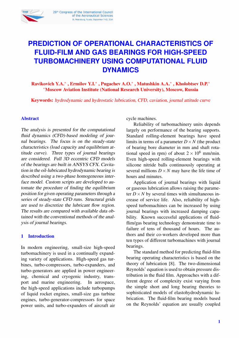
Fig. 1 Schematics of hydrodynamic oil bearing (left) and hydrostatic water bearing (right)
The pressure differential is set between theinlet and outlet boundaries. Boundary conditionsat the outlet boundaries are treated as openingconditions. Rotational speed is defined on theshaft surface.
Steady-state simulations are performed with apseudo-transient coupled CFX solver. High reso-lution advection scheme is used. Calculations forthe high-eccentricity cases are performed withdouble precision.
Numerical convergence is checked by settingtargets for the equation residuals and global bal-ances. Physical convergence criteria imply con-stancy of maximal pressure, maximal gas content(for the cavitated oil bearing), and forces arisingin the fluid film.
All three bearings are modeled using similarframework. Specific features of the models aredescribed below.
3.1 Oil Bearing
Oil film is modeled as incompressible mediumtaking into account cavitation effects.
The oil density is 820 kg/m3. Dependency ofthe oil dynamic viscosity on the oil temperatureis taken into account by the following expression(dynamic viscosity is in [Pa·s], oil temperature isin [K])
µ =−8.589×10⁻⁴T +0.6034
T −282.7(1)
The operating regimes of the oil hydrody-namic bearing may include operation under cavi-tated conditions. Cavitation is the phenomenonof rupture of liquid phase and formation ofgaseous cavities due to decrease in pressure atconstant temperature. Cavitation can be dividedinto gaseous (due to ventilation from the sur-roundings, emission of gases dissolved in theliquid phase) and vaporous (phase change) cav-itation. However, conventional simplified ap-proaches used in the journal bearing models donot distinguish between the two types of cavita-tion. A recent review on the cavitation in journalbearings can be found in [3].
Cavitation of the oil film is modeled usinga two-phase homogeneous interface model witha predefined saturation pressure. A differentialtransport equation is introduced for volume va-por fraction. The Rayleigh-Plesset equation isused to describe the mass transfer terms associ-ated with grow and collapse of gas bubbles.
The gaseous phase is considered to be air.The mean bubble diameter required for the ap-plied cavitation model is set to be 2.0×10⁻³ mm.
Shaft rotational speed is set to 1000 rpm forthe oil bearing. Pressure drop is 1.0 bar.
3.2 Gas Bearing
The air flow in the aerodynamic gas bearing ismodeled as compressible flow with the Thermal
3
RAVIKOVICH, ERMILOV, PUGACHEV, MATUSHKIN, KHOLOBTSEV
Energy formulation. Ideal gas law is used for airat ambient temperature. Static pressure value of1.0 bar is set on both opening boundaries of thegas bearing.
Shaft rotational speed for the gas bearing iscalculated from the bearing number defined as
Λ =6µω
pa
(0.5D
C
)2
(2)
The rotational speed values are in the range of6700 rpm to 135 280 rpm.
3.3 Water Bearing
The water hydrostatic bearing is assumed to op-erate at constant pressure supply.
Water film is modeled as incompressibleisothermal medium. Water properties are takenat the ambient temperature of 25◦C.
The total pressure of 6.0 bar is set at the ori-fice inlets. Ambient static pressure is set at theoutlet boundaries. Two rotational speed cases(7000 rpm and 15000 rpm) are considered.
3.4 Grid Generation
Generation of computational grids is performedin a commercial software ANSYS ICEM CFD.
Structured hexahedral O-grids are used in theanalysis. Depending on the shaft position, re-calculation of the clearance geometry, regener-ation of the mesh and check of the grid qualityare performed automatically for all types of thestudied bearings. Such automation realized bytcl/tk scripts in ICEM CFD simplifies greatly theprocess of determination of the journal attitudecurves.
Results of the grid independence study per-formed for the oil bearing were reported in [11].It was shown that even as dense grids as about 77million nodes demonstrated visible deviation inthe maximum peak of pressure in the oil film. Us-ing that data and based upon a trade-off betweenthe computational costs and required accuracythe following computational meshes believed toprovide sufficiently grid-independent results areapplied in the analysis: 4 662 240 nodes for theoil bearing, 7 880 016 nodes for the gas bearing,
and 3 299 256 nodes for the water bearing. Com-putation mesh for the water bearing is shown inFigure 1.
3.5 CFD Simulation
CFD simulations are performed for differentcases of steady load and shaft rotational speed.The magnitude of the load is simulated by chang-ing the eccentricity of the shaft in two directions.The main interest of this study is in predicting thejournal attitudes curves, i.e. functions of the jour-nal steady-state position at various vertical loads.
The approach of finding the steady-state posi-tion for a given load is based on the iterative cor-rection of the rough estimation of the shaft eccen-tricity until the target load value is reached. Thesearch process is to stop when the hydrodynamicreaction on the shaft is zero (within a tolerance)in the horizontal direction and equals to the pre-defined value in the vertical direction.
4 Lubrication Theory
The bearings are also modeled with the conven-tional lubrication theory to compare the predic-tions by both approaches.
In the lubrication theory the fluid film flowin the journal bearings is described by the two-dimensional Reynolds’ equation. The Reynolds’equation takes into account turbulence in the filmby using semi-empirical correlations for the tur-bulence factors (Constantinescu’s model).
The Reynolds’ equation is solved numeri-cally using the finite element method on thestructural uniform mesh of rectangles. The hy-drodynamic reaction of the bearing is determinedby integrating the pressure distribution p on thebearing surface.
Fluid-film rupture appearing in the divergentzone of the bearing clearance (negative pressureregion) is taken into account by simple bound-ary conditions. The lubrication theory model isimplemented in the in-house code for the journalbearing analysis running in MATLAB. Details onthe used lubrication theory model can be foundin [10].
4
PREDICTION OF OPERATIONAL CHARACTERISTICS OF JOURNAL BEARINGS USING CFD
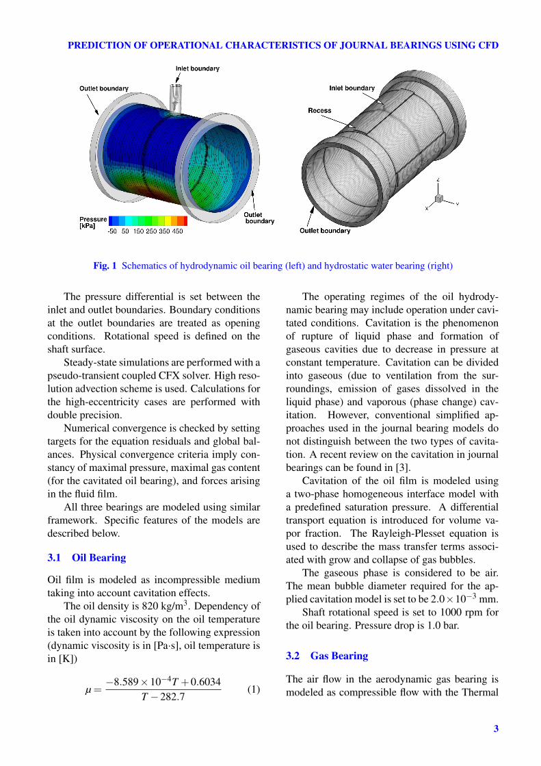
Fig. 2 Predicted Flow Characteristics in the OilBearing for Different Loads
5 Analysis of the Results
This section summarizes the numerical resultsobtained for the three studied bearings. The cal-culations are performed on a multi-core desktopcomputer with 128 GB of memory.
5.1 Oil Bearing
Typical pressure distribution and streamlines inthe oil bearing are shown in Figure 1. Distribu-tions of pressure and volume fraction of gaseousphase at the middle section of the bearing areshown in Figure 2 for different loads. Pressuremagnitude is shown as ratio of the absolute pres-sure to the maximum pressure in the film. Thecircumferential position of the single orifice canbe clearly identified from the pressure distribu-tion curve for the small loads. Substantial cavita-tion occurs at the load of 1000 N and higher. Asthe load increases the cavitating zone expands inthe direction of the smallest clearance.
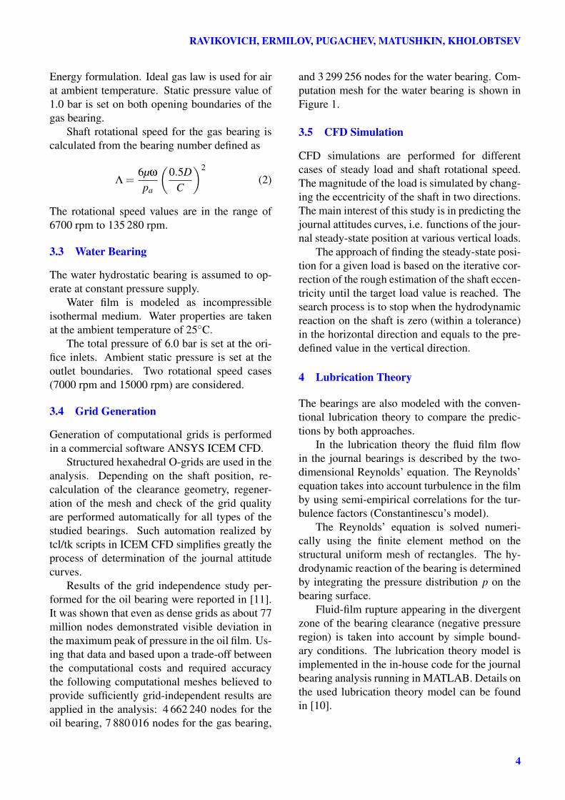
The predicted journal attitude curve obtainedby approximating calculated cases of differentloads is shown in Figure 3. The dashed curvedemonstrate the stator surface.
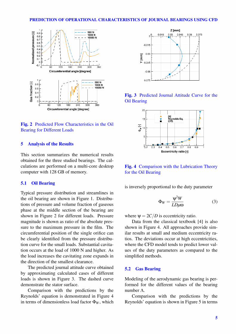
Comparison with the predictions by theReynolds’ equation is demonstrated in Figure 4in terms of dimensionless load factor ΦW , which
Fig. 3 Predicted Journal Attitude Curve for theOil Bearing
Fig. 4 Comparison with the Lubrication Theoryfor the Oil Bearing
is inversely proportional to the duty parameter
ΦW =ψ2WLDµω
(3)
where ψ = 2C/D is eccentricity ratio.Data from the classical textbook [4] is also
shown in Figure 4. All approaches provide sim-ilar results at small and medium eccentricity ra-tios. The deviations occur at high eccentricities,where the CFD model tends to predict lower val-ues of the duty parameters as compared to thesimplified methods.
5.2 Gas Bearing
Modeling of the aerodynamic gas bearing is per-formed for the different values of the bearingnumber Λ.
Comparison with the predictions by theReynolds’ equation is shown in Figure 5 in terms
5

RAVIKOVICH, ERMILOV, PUGACHEV, MATUSHKIN, KHOLOBTSEV
Fig. 5 Comparison with the Lubrication Theoryfor the Gas Bearing
of the dimensionless load capacity
W =W
paDL(4)
Again, data from the classic textbook on aerody-namic bearings [14] is also shown.
Results obtained with the in-house code forsolving Reynolds’ equation are shown only forthe case Λ = 1.2. The predictions are in goodagreement, though the Reynolds’ equation over-predicts the bearing load capacity at high eccen-tricity ratio compared to the CFD results. TheReynolds’ equation results are virtually identicalto those taken from [14].
5.3 Water Bearing
The journal attitude curves calculated for the wa-ter bearing are shown in Figure 6. Two cases ofdifferent rotational speed are presented.
At the rotational speed of 7000 rpm the atti-tude curve shape is close to a line starting fromthe center of the bearing, which is typical for thehydrostatic bearings lubricated by incompress-ible fluid [9, 12].
At the higher rotational speed the journal pro-duces the hydrodynamic effect comparable withthe hydrostatic reaction. The hydrostatic bearingoperates in the hybrid mode. Therefore the jour-nal attitude curve becomes more nonlinear.
6 Conclusions
The CFD-based modeling of the fluid-film andgas bearings is very time consuming as comparedto the bearing analysis based on the Reynolds’
Fig. 6 Predicted Journal Attitude Curve for theWater Bearing
equation. Nevertheless, using an automation ofthe CFD analysis (pre-processing, solving, andpost-processing) makes it possible to reduce sig-nificantly time and effort necessary for the calcu-lation of journal bearing operational characteris-tics.
The CFD predictions demonstrate good cor-relation with the available data for both oil andgas journal bearings studied in this work. How-ever, as expected, deviations between the theoret-ical approaches are observed for the journals op-erating at high eccentricities and high rotationalspeeds.
The developed CFD models can now be ap-plied for further studies on advanced journalbearing technology. In particular, the aerody-namic gas bearing model can be extended tomodel foil air bearings, for which an additionallimitation of using Reynolds’ equation is con-nected with large differences in the radial clear-ance between the shaft and the foils. Also, thedeveloped models can be coupled with an appro-priate method for determining rotordynamic co-efficients of the bearings. This is, however, be-yond the scope of this work.
References
[1] Almqvist T and Larsson R. Some remarks on thevalidity of Reynolds equation in the modelingof lubricant film flows on the surface roughnessscale. ASME J. Tribology, Vol. 126, pp. 703-710,2004.
6

PREDICTION OF OPERATIONAL CHARACTERISTICS OF JOURNAL BEARINGS USING CFD
[2] ANSYS, Inc. ANSYS CFX-Solver theory guide.Release 14.5, 2012.
[3] Braun MJ and Hannon WM. Cavitation forma-tion and modelling for fluid film bearings: a re-view. Proc. IMechE, Part J: J. Engineering Tri-bology, Vol. 224, pp. 839-863, 2010.
[4] Chernavsky SA. Journal bearings. Moscow:Mashgiz, 1963. (In Russian)
[5] Dobrica MB and Fillon M. About the validity ofReynolds equation and inertia effects in texturedsliders of infinite width. Proc. IMechE, Part J:J. Engineering Tribology, Vol. 223, pp. 69-78,2009.
[6] Guo Z, Hirano T and Kirk RG. Applica-tion of CFD analysis for rotating machinery—Part I: Hydrodynamic, hydrostatic bearings andsqueeze film damper. ASME J. Eng. Gas TurbinePower, Vol. 127, pp 445-451, 2005.
[7] Hélène M, Arghir M. and Frêne J. CombinedNavier-Stokes and bulk-flow analysis of hybridbearings: radial and angled injection. ASME J.Tribology, Vol. 127, pp. 557-567, 2005.
[8] Lang OR, and Steinhilper W. Gleitlager.Springer-Verlag, 1978.
[9] Peeken H. Hydrostatische Querlager. Konstruk-tion, Vol. 16(7), pp. 266-276, 1964.
[10] Pugachev AO, Tykhomirov VV, SheremetyevAV, Spilenko OI and Timchenko ID. Sensi-tivity analysis of squeeze film dampers usingReynolds equation. Proc 8th IFToMM Interna-tional Conference on Rotor Dynamics, KIST,Seoul, Korea, TuC1-3, pp. 454-462, 2010.
[11] Pugachev AO, Ravikovich YA, Ermilov YI,Kholobtsev DP and Matushkin AA. CFD-basedmodeling of oil and gas journal bearings us-ing commercial software packages. Vestnik ofSamara State Aerospace University, No. 41(3),pp. 211-220, 2013. (In Russian.)
[12] San Andrés L, Childs D and Yang Z. Turbulent-flow hydrostatic bearings: Analysis and exper-imental results. Int. J. Mech. Sci., Vol. 37, pp.815-829, 1995.
[13] San Andrés L. Bulk-flow analysis of hybridthrust bearings for process fluid applications.ASME J. Tribology, Vol. 122, pp. 170-180, 2000.
[14] Sheinberg SA et al. Gas-lubricated journalbearings. Moscow: Mashinostroenie, 1979. (InRussian)
[15] Tucker PG and Keogh PS. A generalized compu-
tation fluid dynamics approach for journal bear-ing performance prediction. Proc. IMechE, PartJ: J. Engineering Tribology, Vol. 209, pp. 99-108, 1995.
[16] Uhkoetter S, aus der Wiesche S, Kursch Mand Beck C. Development and validation ofa three-dimensional multiphase flow computa-tional fluid dynamics analysis for journal bear-ings in steam and heavy duty gas turbines.ASME J. Eng. Gas Turbine Power, Vol. 134, pp.102504-8, 2012.
Nomenclature
C = Radial clearanceCr = Recess depthD = Bearing diameterD2 = Downstream region diameterd = Orifice diameterD×N = Bearing speed factorL = Bearing length` = Orifice length`r = Recess axial lengthL2 = Shaft lengthp = Pressurepa = Ambient pressureT = TemperatureW = Load capacitywr = Recess widthΛ = Bearing numberµ = Dynamic viscosityρ = DensityΦW = Load factorψ = Eccentricity ratioω = Rotational speed
7 Contact Author Email Address
Copyright Statement
The authors confirm that they, and/or their company or or-ganization, hold copyright on all of the original materialincluded in this paper. The authors also confirm that theyhave obtained permission, from the copyright holder of anythird party material included in this paper, to publish it as
7

RAVIKOVICH, ERMILOV, PUGACHEV, MATUSHKIN, KHOLOBTSEV
part of their paper. The authors confirm that they give per-mission, or have obtained permission from the copyrightholder of this paper, for the publication and distribution ofthis paper as part of the ICAS 2014 proceedings or as indi-vidual off-prints from the proceedings.
8