prediction of tread geometry influence on ply steer ... · pdf fileprediction of tread...
TRANSCRIPT
SIMULIA India Regional Users Meeting ‘11 Page 1 of 9
Prediction of tread geometry influence on Ply steer Residual Aligning Torque (PRAT) T.Muthu Siva Sankar*, P. Sankarganesh, S.K.P.Amarnath and Peter Becker
Apollo Tyres Ltd., Vadodara, India
Key words: Tyre, PRAT, Vehicle Pull, Tread Pattern
ABSTRACT:
Ply steer residual aligning torque (PRAT) is one of major parameters which influences vehicle pull. A
vehicle pull problem is directly related to safety and comfort. The value of PRAT is influenced by the
various constructional parameters and treads pattern designs. Experimental evaluation of PRAT is
time consuming and costly. This paper presents the numerical procedure for computation of PRAT
values of tyres and investigation is restricted to change in tread pattern design. This procedure
helps the tyre designers to meet/balance the Vehicle pull requirements at an early stage of product
development.
Introduction:
Among the problems related to vehicle stability, straight running of a vehicle is a relevant safety
feature of vehicle performance. Vehicle pull/drift can
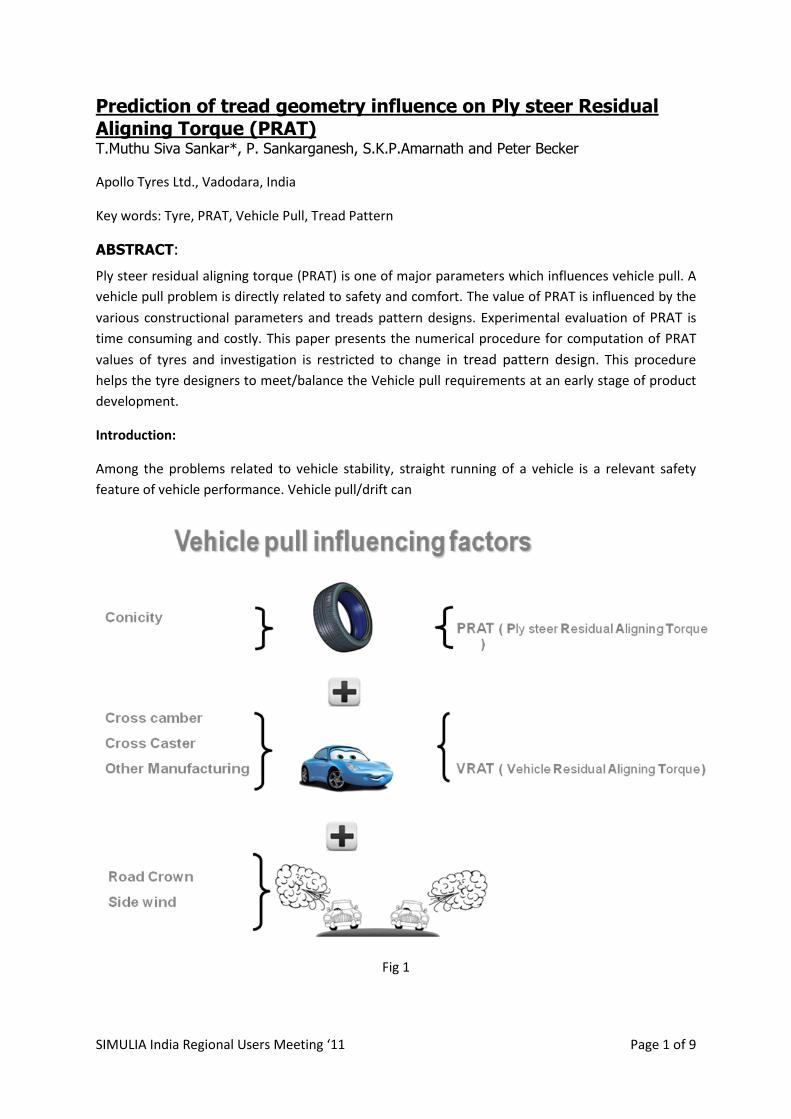
Fig 1

SIMULIA India Regional Users Meeting ‘11 Page 2 of 9
be easily sensed by driver. Vehicle drifts to one particular side when there is an asymmetry present
either in steering system/suspension system, tyre uniformity, road crown or incompatible
interaction among them. Vehicle pull is affected by force and moment generated either by tyre or
suspension system.
Major parameters causing the pull problem are includes PRAT and conicity of tires, road crown, cross
camber, cross caster and other manufacturing non uniformity of the vehicle. Force and moment
behaviours are function of tyre body parameters (profile, belt angle, belt constructions etc) and
contact behaviour of tread pattern by the geometry of tread pattern.
To minimize vehicle drift VRAT should be counter balanced by PRAT. So co work between vehicle
and tyre industry is mandatory to optimize the vehicle pull. This paper describes the effect of pattern
in particular and influences of Shoulder lateral groove angle on ply residual aligning torque.
PRAT
A typical radial tyre structure is made with multiple layers of plies bonded together. The individual
plies have various prescribed orientations of carcass layer which are parallel to the meridonial
direction and anti symmetric belt package in the crown region. The classical lamination theory
assumes that the orthotropic layers are perfectly bonded together with an infinitely thin bond line
and the deformations across the bond line are continuous. Generally, the multi-ply systems twist
and bend when subjected to simple tensile load. The result is a combination of bending, shearing
and stretching of the laminate. Moreover If the tyre is free rolling, the toroidal shape of tyre (shown
in fig2) becomes flat at the contact patch, so lateral and longitudinal shear stresses are generated in
the contact area (tread blocks) and additional in plane shear also occurs due to change in belt
tension at contact patch. These shear stresses applied to the individual tread blocks cause coupled
reaction forces, resulting in an aligning torque. Thus radial tyres generate measurable lateral force
and self aligning moment under straight rolling condition. Ply steer side force is an inherent property
of a belted radial tyre which is the nonzero side force at zero slip angles.
Fig 2

SIMULIA India Regional Users Meeting ‘11 Page 3 of 9
PRAT is defined as the level of tyre aligning torque at the slip angle where the lateral force is zero. The phenomenon is governed by the structural parameters of both tire body and treads pattern as
Fig 3
Well as the frictional dynamics of rolling tire, which is mechanically complex? Conventionally, tyre PRAT is adjusted through the classical approach in which trial productions of tires by adjusting the construction and tread design parameters are too costly and time-consuming and there has been a demand for a new approach to address the above method. The mechanism of PRAT can be decomposed into two effects, i.e. the pattern effect and the body effect. The pattern effect is usually extracted by changing the signs of belt cord angle about a particular tread design. The pattern effect is can be calculated by below formula. The pattern effect = (PRAT1 + PRAT2)/2 PRAT1 – PRAT evaluated at Regular belt cord orientation PRAT1 – PRAT evaluated at Reverse belt cord orientation Tire engineers have to evaluate the sensitivity of the tread pattern design to PRAT on the occasion of accommodating the design to several markets of different PRAT requirements. Modelling Strategy: To investigate the effects of Tread Pattern, the tread pattern is modeled with longitudinal and lateral
grooves consisting of 50 numbers of pitches around the circumference. Tread and carcass is
modelled separately and later Tread region is tied with carcass model. Rubber components are
modeled with continuum 8 noded brick and 6 noded penta elements. Reinforcements which are
embedded in rubber elements are modeled with 4 noded membrane elements. Road and rim are
modelled as analytical rigid. Coulomb friction law is used between tyre/ rim as well as with Tyre/
road.

SIMULIA India Regional Users Meeting ‘11 Page 4 of 9
Fig 3
Under the assumption of cyclic symmetry inflation and rim mounting was performed in single pitch.
Using symmetric model generation and symmetric result transfer, full tyre model was generated.
Vertical loading was performed in the subsequent step.
Steady State Rolling Analysis
The steady state dynamic interaction between tyre and road is investigated using the steady state
transport analysis capability available in Abaqus. Steady state transport is carried out by using mixed
Langrangian/Eulerean formulation. This option uses a reference frame attached to the wheel axle,
which does not rotate with the tire. The tire then rotates through this frame. Stream lines are
defined through axis of rotation in symmetric model generation and the path through which
material will flow. This kinematic description that converts the steady-state moving contact
problem into a purely spatially dependent simulation in which rigid body rotation is described in a
spatial or Eulerian manner, and deformation, which is now measured relative to the rotating rigid
body, is described in a Lagrangian manner.
This approach represents a huge saving in computational overhead when compared with a transient
analysis, with fine mesh defined along the entire surface of the deformable tire. Restarting from the
solution of the static deflection analysis, the steady state transport option is first used to obtain the
straight line steady state rolling conditions while varying the tire angular spinning velocities at the
desired constant road speed (30 km/hr was used in this study). With the straight line free rolling
solution obtained, the steady state simulation of the tire when subjected to a prescribed slip angle is
then implemented and the tire’s dynamic response in terms of the lateral forces and aligning
moments is obtained.

SIMULIA India Regional Users Meeting ‘11 Page 5 of 9
Variants:
Three variants have been studied which are in 3 groups. In group I, belt lay is changed from regular
orientation to reverse orientation. In group II, shoulder lateral groove angle is varied from 0 to 40
degrees. In Group III, orientation of pattern is reversed. Refer below fig 4
Fig 4
Influence of belt lay:
When reversing the belt lay the sign of the lateral force generated reverses from the reference belt
lay and there by PRAT also reverses.

SIMULIA India Regional Users Meeting ‘11 Page 6 of 9
Fig 5a
Influence of shoulder Lateral groove angle:
The value of PRAT increases with increasing groove angle up to 30 degree and any further angle
increase reduces the PRAT values.
Fig 5b
Influence of Pattern Reverse:
When reversing the pattern orientation the PRAT value decreases in magnitude by half.

SIMULIA India Regional Users Meeting ‘11 Page 7 of 9
Fig 5c
Validation:
2 tyres were hand carved, one with regular pattern orientation and the other with reverse tread
pattern orientation. PRAT values were evaluated in indoor pulley wheel.
Fig 6a
Fig 6b

SIMULIA India Regional Users Meeting ‘11 Page 8 of 9
Fig 6c
Fig 6c, compares the experimental footprint pressure distribution against the simulated foot print
and both are comparable. Both simulated and experimental footprint pressure values in the
shoulder region shows relatively higher pressure intensity. The experimental and simulated PRAT
values are shown in the table below.
Result and Discussion:
Based on the investigation, highest influence is
observed when we reverse the belt lay orientation
and followed by reversing the pattern orientation and
then shoulder lateral angle change. The differences
between experimental values against simulated
values can be improved by incorporating the viscous
parameters. The experimental and simulated prat
values are in good agreement behaviourally.
Item PRAT ( Nmm)
Abaqus
Simulation
Experimental
Regular
Pattern
1246 1643
Reverse
Pattern
623 380

SIMULIA India Regional Users Meeting ‘11 Page 9 of 9
Conclusions:
Abaqus evaluation of PRAT results are very well in agreement with experimental results. With this
approach Pattern PRAT setting, tuning can be done at tyre design stage and leaves an opportunity to
cooperate with Vehicle manufacturers at the design stage itself. PRAT evaluation through Abaqus
simulation saves a lot of time and cost.
Acknowledgement
The authors wish to express their appreciation to the Apollo tyres management for permitting to share the presentation. And special thanks to both Product Development and Design & Development teams of R&D Apollo Tyres Ltd for their constant support.
References
1. Abaqus/Standard User’s Manual, Version 6.10
2. Okonieski, R. E., Moseley, D. J., Cai, K. Y., "Simplified Approach to Calculating Geometric
Stiffness Properties of Tread Pattern Elements," Tire Science and Technology, TSTCA, Vol.
31, No. 3, 2003
3. K. Ohishi, H. Suita, and K. Ishihara, " The Finite Element Approach to Predict the Plysteer Residual Cornering Force of Tires ," Tire Science and Technology, TSTCA, Vol. 30,
No. 2, 2002
4. Kabe, K. and Morikawa, T., "A New Tire Construction Which Reduces Ply Steer," Tire Science and Technology, TSTCA, Vol. 19, No. 1, 1991.
5. Gent, A. N., The Pneumatic Tire, NHTSA US DOT, Washington, D.C., August, 2005