preevision - spes 2020 - software plattform embedded systems 2020
TRANSCRIPT

Manual
PREEvisionVariant management
Version 5.0 BetaEnglish

Imprint
Vector Informatik GmbHIngersheimer Straße 2470499 Stuttgart, Germany
The information and data contained in this documentation may be changed without prior notice. Without the express written permission ofVector Informatik GmbH, no part of these documents may be duplicated or transmitted for any purpose, regardless of the manner ormedium, electronic or mechanical, in which this occurs. All technical details, drawings, etc. are subject to the protection of copyright law.© Copyright 2011, Vector Informatik GmbH. Printed in Germany.All rights reserved.
Contents
1 Variant management concepts 51.1 Variant management artifacts 6
1.2 Basic knowledge: the variant management structure 8
2 Variant management perspective 112.1 VM Architecture View 13
2.2 VM Group Structure 15
2.3 Variant Structure 18
2.4 VM Propagation Rule Preview 19
2.5 Template View 20
2.6 Set Content View 23 2.6.1 Conflict highlighting and solving in the Set Content View 252.7 Template Compare View 26
2.8 Variant Rule Group View 27
3 Variant preferences 31
4 The variant management example 33
5 Step 1: Creating a variant model 35
6 Step 2: Creating feature concepts for the variant 37
7 Step 3: Defining variant configurations 417.1 Variant permutation 41
7.2 Refining variants 42
8 Step 4: Connecting the variant model with the E/E model 45
9 Step 5: Creating variant conditions 499.1 About guards 51
10 Step 6: Using of variants 57
11 Working with the variant diagram 61
12 Using parameters variant specific 65
Contents
© Vector Informatik GmbH Version 5.0 Beta - 3 -
13 Propagating variants 67
Index 71
Contents
- 4 - Version 5.0 Beta © Vector Informatik GmbH

Variant management concepts
The variant management provides a highly configurable mechanism to model variantsbased on the E/E architecture. Product lines of an E/E architecture are modeled inPREEvision as 150%-model that mean the model includes all components that can betailored into different subsets. These subsets – the variants – are representing specificproducts of one product line.
The equipment part is used for specifying which features should be included in anarchitecture variant as standard equipment and which are to be optional. A single typemay have more than one equipment concept available. A common example is theavailability of low and high equipment concepts. As equipment concepts determinewhat to include in an architecture variant, technical concepts represent theimplementation itself. Thus, equipment concepts build one starting point forarchitecture analysis.
In development projects, hundreds of thousands of architecture artifacts represent asingle type product. For product line architecture, the number of artifacts is higheralthough the reuse of common parts avoid a linear growth over the number of producttypes. To keep track of all the artifacts and their composition to at least parts of technicalconcepts the artifacts can be structured in sets. These sets can be composed totechnical alternatives for each of the concepts to be implemented. A choice ofalternatives represents a complete architecture variant (in a technical manner).
> Architecture analysis
One objective of modeling variants is the exploration of the architecture design withthe focus to optimize it. Almost everything is possible to analyze: what is the bestsoftware concept or the best bus communication, which variation of the geometry
Overview
Equipment aspects ofvariant management
Technical aspects ofvariant management
Use Cases
Variant management concepts
© Vector Informatik GmbH Version 5.0 Beta - 5 -

is the cheapest, how much is the wiring harness, and so on. With the analysis ofexisting architecture variants it is possible to benchmark how well an architecturevariant meets requirements.
> Architecture evaluationRun an evaluation to verify if the architecture design is valid and consistent.
> Compare modelsOne point is to compare different architectures (e.g. different partitioning scenariosor network concepts) with each other and to take the best solution after thecomparison into account for further modeling.
> Group artifactsIt can also be used to group model artifacts and make them easily accessible.
> Quick variant generationAn independent variant model allows a flexible variant modeling.
A variant can be 100% or 120% out of the 150% model.> Build variants by using automatic propagation (defined by rules).> Use variant-conditions to define dependency or exclusion.> Use consistency-checks to verify variant-conditions.> Content of variants can be highlighted in all diagrams.> Different variants can be evaluated.
Example: Design various alternatives to test one function on different ECUs (busload).Design alternatives that describe different approaches of realization.
Key data of variants
Variant management concepts
- 6 - Version 5.0 Beta © Vector Informatik GmbH

Variant management artifacts
Artifact DescriptionConcept Space The Concept Space represents a bundle of technical
concepts that are available for a vehicle and must beconsidered for a variant. It is the base for creating anArchitecture Variant. The specific concepts arerepresented by the Concept Template artifacts. It ispossible to create many Concept Spaces with differentConcept Templates assigned to it. One ConceptTemplate can be part of different Concept Spaces. Thatallows a very flexible architecture setup.
Concept Template The Concept Template is standing for the technicalpartial solution. It describes all possibleimplementations of a certain assembly (ConceptSpace) of the vehicle.They hold their Alternatives and let the user chooseexactly one Alternative for one Concept Template.The Concept Templates are directly associated with aConcept Space.
Alternative There exists Concept Template and EquipmentTemplate Alternatives.The Concept Template Alternative represents onespecific technical solution for a Concept Template.The Equipment Template Alternative represents theavailable vehicle configurations.For every template exactly one Alternative can beselected by the user. Alternatives are created for theaccording template.
EquipmentTemplate
The Equipment Template describes equipmentcharacteristics from the customer point of view. It holdsits Alternatives and lets the user choose exactly one ofthem for one Architecture Variant. Based on the chosenEquipment Template Alternative, the accordingConcept Template Alternatives, the implementation forthe feature, are assigned. The result is standing forexactly one Architecture Variant.There may exist different implementation concepts forthe same equipment concept.The Equipment Template isn’t directly assigned to theConcept Space because it represents the features andrequirements the customer can experience and it is notpart of the technical solution.It’s also possible to create options for different trimlevels of a vehicle, e.g. Equipment Template“VehicleEquipmentOptions” with the three Alternatives“FullEquipment”, “MostSoldEquipment” and“BaseEquipment”.
1.1
Available artifacts forthe variantmanagement
Variant management concepts
© Vector Informatik GmbH Version 5.0 Beta - 7 -

Artifact DescriptionArchitectureVariant
The Architecture Variant is one specific variant. Itconsists of exactly one equipment concept thatdescribes the features that are included in the variant(Equipment Template Alternative). Also one or moretechnical implementation concepts for the feature areassigned (Concept Template Alternatives).The sum of the chosen Concept- and EquipmentTemplate Alternatives results in one conceptimplementation variant of the according ConceptSpace.To structure variants in a well arranged way it is possibleto create many Architecture Variants.
Set Sets are used as a structure element. They can be filledwith artifacts for grouping them and it is possible tonesting them into each other.Sets allow quickly change a variant’s content. They arehighly reusable if they are modeled in the rightgranularity. One Set may and should be used bymultiple templates.
> Variant management concepts> Variant management perspective> Working with the variant diagram> Variant preferences> Basic knowledge: the variant management structure
Further information
Variant management concepts
- 8 - Version 5.0 Beta © Vector Informatik GmbH

Basic knowledge: the variant management structure
The variant model is modeled separately from the E/E model. The connection betweenboth models occurs later when the variant concept is completed. The structure of thevariant model starts with a Concept Space (bundle of technical implementationconcepts). To the Concept Space the technical implementation concepts, the ConceptTemplates, and the Architecture Variants (one specific variant) are assigned. To anArchitecture Variant one or more Concept Templates may be assigned. For everyConcept Template exact one Alternative may be chosen.The Equipment Templates are independent from the Concept Space. EquipmentTemplates describes the customer features to be represented by the variant. Exactlyone Equipment Template can be assigned to an Architecture Variant. EquipmentTemplates also contains Alternatives. For an Equipment Template one Alternative maybe selected.The Set is the connection between the variant model and the E/E model. The Set canbe assigned to an Architecture Variant. The assigned Set in turn contains assigned E/E artifacts. So the E/E artifacts are indirectly linked to the variant.At the end every Architecture Variant is one certain combination of one EquipmentTemplate Alternative and one or more Concept Template Alternatives. Thesecombinations represent several different 100% models. > Variant management concepts> Variant management perspective> Working with the variant diagram> Variant preferences> Variant management artifacts
1.2
The variant model
Further information
Variant management concepts
© Vector Informatik GmbH Version 5.0 Beta - 9 -

Variant management concepts
- 10 - Version 5.0 Beta © Vector Informatik GmbH

Variant management perspective
The Variant Management perspective provides all views that are used for creatingand editing an Architecture Variant with all its content.
Open the Variant Management perspective via the
icon in the main toolbar.
Activate or switch a variant via the drop-down list. Also parts of a variant canbe activated, e.g. Alternatives.
The Model View provides an overview of all variant artifacts in a hierarchicalstructure.
The views provided in the Variant Management perspective are displayed inthis area. In the table below you will find an overview of the available variantmanagement views.
Overview
Variant management perspective
© Vector Informatik GmbH Version 5.0 Beta - 11 -

View UseVariant Management ArchitectureView
The VM Architecture View can be used to:> configure Concept Alternatives> and Equipment Alternatives for an
Architecture Variant.
VM Set Structure The VM Group Structure can be used to:> get a list of all variant artifacts in a tree
view.> model a hierarchical view of the
variant artifacts.
Variant Structure The Variant Structure can be used to:> get an overview of the templates and
its Alternatives of the currently activevariant.
> get an overview which Sets arecontained in the Alternatives.
VM Propagation Rule Preview The VM Propagation Rule Preview canbe used to:> get a preview of a Propagation Rule
that is selected in the Model View.
Template View The Template View can be used to:> add content to a Concept or an
Equipment Template, e.g. a Set.> organize the content of templates.
Views of the VariantManagementperspective
Variant management perspective
- 12 - Version 5.0 Beta © Vector Informatik GmbH

View UseSet Content View The Set Content View can be used to:
> assign content to variant artifacts,e.g. Sets or Alternatives.
> get the information which areincluded or excluded artifacts of theselected artifact.
Template Compare View The Template Compare View can beused to:> get an overview which artifacts are
contained in which template.
Variant Rule Group View The Variant Rule Group View can beused to:> create new variant propagation rule
groups. Variant Propagation Rulescan be assigned and run as group forthe variant propagation.
Variant management perspective
© Vector Informatik GmbH Version 5.0 Beta - 13 -

VM Architecture View
The VM Architecture View is the central element for setting up a single, validArchitecture Variant that is built up on Concept Templates and their instances and oneEquipment Instance. It consists of different sections. The first section lets the userchoose the Architecture Variant that is about to be configured. The second section listsall Concept Templates and the according Concept Template Alternatives. The user canchoose exactly one Alternative for each Concept Template. The third section lists theEquipment Templates with its Alternatives where exactly one can be chosen. See thenext figure for an overview.
Area Architecture VariantSelect the Architecture Variant that is to be set up here. All its ConceptTemplates and Concept Template Alternatives will be available for set up in thearea Concept Templates. The assigned Concept Space is shown.
Area Concept TemplateThis area holds all Concept Templates with the according Concept TemplateAlternatives that are assigned to the selected Architecture Variant's ConceptSpace.On the left side of the area the Concept Templates are listed as clickablehyperlinks leading directly to the Concept Templates in the Model View whenthey are clicked.The drop-down lists on the right to the Concept Templates provide the ConceptTemplate Alternatives. One may choose exactly one Concept TemplateAlternative per Concept Template for the currently selected ArchitectureVariant (selected in area 1).
Area Equipment TemplateThis area lists all Equipment Templates on the left side and the accordingEquipment Template Alternatives on the right side. Only one EquipmentTemplate Instance can be selected over all Equipment Templates for theselected Architecture Variant.
2.1
Overview
Description of theareas
Variant management perspective
- 14 - Version 5.0 Beta © Vector Informatik GmbH

Navigates to the currently chosen artifact in the Model View.
A new Concept Template Alternative can be created.
Deletion of the currently chosen Concept Template Alternative.
Creates a new Architecture Variant based on the actual chosenArchitecture Variant. It will contain the same Concept Templates inclusivethe selected Alternatives.
> Variant management perspective> Variant management concepts> Working with the variant diagram> Variant preferences
Icons
Further information
Variant management perspective
© Vector Informatik GmbH Version 5.0 Beta - 15 -

VM Group Structure
The VM Group Structure view provides two different views:> The standard view shows the hierarchical structure of the Variant Packages with
the contained Concept-/ Equipment Templates, Concept-/ Equipment TemplateAlternatives, Systems and Sets. The shown hierarchical tree visualizes theassociations between the single variant artifacts as a composite tree.(See figure below on the left side)
> The activatable view shows the structure sorted by kind of artifact.(See figure below on the right side)
The complete Variant Package structure is shown as the root of the tree. Thebetter the Variant Packages were organized; the better is the readability andstructure of the tree shown in the VM Group Structure view.If the [Switch View] button is activated the Variant Packages are not shown.
The Architecture Variants contain the active Concept Template Alternatives thatwere explicitly selected for them. The Sets that are contained by the ConceptTemplate Alternatives are shown as children of them. Nested Sets are shown,too.This structure lets the user navigate through a Concept Template Alternative'sassociated contents - beginning from the Architecture Variant down to the Sets.
2.2
Overview
Variant management perspective
- 16 - Version 5.0 Beta © Vector Informatik GmbH

The Sets with their nested Sets, if existing, are shown in the parent VariantPackage.
All in the Variant Package contained Systems are shown.
Every Concept Template Alternative that exists in the Variant Package is shown.The Alternatives are structured independently of any assigned ArchitectureAlternative. So it is an overview of all Alternatives that are provided for the user.
The Equipment Template Alternatives of all in the Variant Package containedEquipment Templates are shown.
Caution: Since Sets can be nested into each other it is possible to create a containmentcycle.See the following example:1. Set 1 is nested in Set 2.2. Set 2 is nested in Set 1.
This cases a never ending sub tree in the tree of the VM Group Structure view.One should avoid such cycles since the resulting Architecture Variant implementsthis cycle, too. It results in a multiple association of model artifacts into oneArchitecture Variant.
Collapses the tree.
Removes the parent reference of the selected artifact. This is mainlyused to remove nested Sets.
Switches the view from the Variant Package oriented view to an objecttype oriented view where all elements are grouped by their types.
The first two options provide the undo/redo functionality of PREEvision.The menu entry New can be used to create new Systems, Variant Packages and Sets.This option is only available if a suitable parent object is selected and the accordingmodel part is checked out (when a database is used).Remove Parent Reference removes referenced objects from their parents in theview's tree - as described above this feature is mainly used for removing nested Sets.Sets can be nested into other Sets by moving them via drag and drop on the targetSet. > Variant management perspective> Variant management concepts> Working with the variant diagram> Variant preferences
Icons
Shortcut menu
Further information
Variant management perspective
© Vector Informatik GmbH Version 5.0 Beta - 17 -

Variant management perspective
- 18 - Version 5.0 Beta © Vector Informatik GmbH

Variant Structure
The Variant Structure view displays associated Concept- and Equipment TemplateAlternatives and Sets for the currently active Architecture Variant. The presented treestructure is the same as described in VM Group Structure. The only difference is thatthe Variant Structure view focuses only on the activated variant artifact. See the nextfigure showing the Variant Structure view.
Collapses the tree.
Removes the parent reference of the selected artifact. This is mainlyused to remove nested Sets.
> Variant management perspective> Variant management concepts> Working with the variant diagram> Variant preferences
2.3
Structure of activevariant
Icons
Further information
Variant management perspective
© Vector Informatik GmbH Version 5.0 Beta - 19 -

VM Propagation Rule Preview
The VM Propagation Rule Preview visualizes a Propagation Rule's diagram with theshort and a long description for it.
When a propagation rule is selected in the Model View the according rule is shown inthe VM Propagation Rule Preview. The preview shows the rule diagram, its name, ashort and a long description. The rule can not be edited in this view – you have tochange into the Propagation Rule Editor perspective to edit. > Variant management perspective> Variant management concepts> Working with the variant diagram> Variant preferences
2.4
Overview
Further information
Variant management perspective
- 20 - Version 5.0 Beta © Vector Informatik GmbH

Template View
The Template View provides an overview of the existing Sets in the variant model andtheir usage. You can also create new variant artifacts, e.g. Alternatives or ArchitectureVariants, in this view and edit existing ones.
The drop-down list provides all templates in the model. Select the ConceptTemplate or Equipment Template for editing or viewing.
With the icon you navigate to the selected template in the Model View.
The Number of units may be optionally used to enter a unit count that is validfor the whole template. In combination with this count the percentages of theSets’ unit count can be determined (see 4).
The column Model Groups lists all Sets that are assigned to the selectedtemplate.
The Nr of units column holds the absolute amount of units for this Set.The column Nr of units in % shows the relative amount of units for this Set. Thisinformation is used for e.g. cost analyses.
The column Containment indicates - if activated - that this Set inclusive allAlternatives is assigned to this template.All template Alternatives are dynamically shown as columns. The name of theAlternative is used as column header. For each Set the Alternatives can bechosen by selecting or unselecting the checkboxes.
The view's toolbar actions are listed in the following table:
Toggles automatically all features that belong due to conditions to the actualselected or unselected feature.
Starts the propagation for multiple selected features at once.
Highlights how the new selected feature affects the variant.
Switches the selected Alternative (table row) as active variant.
Toggles the table view between a list without checkboxes and a list withpreceding checkboxes.
Exports the actual shown table into an Excel file.
Removes the reference betweens a Set and the selected template. Theremoved Set is afterwards not included to the template anymore.
Creates a new Architecture Variant artifact. For that action an EquipmentTemplate has to be chosen in the drop-down list because an automaticpropagation is started based on this template. Also select an Alternativecolumn. The new created Architecture Variant will contain the activeAlternatives of the chosen column.
2.5
Overview
Variant management perspective
© Vector Informatik GmbH Version 5.0 Beta - 21 -
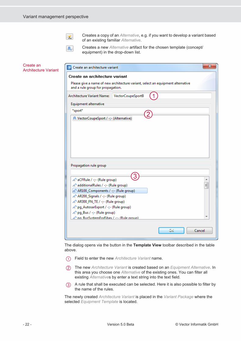
Creates a copy of an Alternative, e.g. if you want to develop a variant basedof an existing familiar Alternative.
Creates a new Alternative artifact for the chosen template (concept/equipment) in the drop-down list.
The dialog opens via the button in the Template View toolbar described in the tableabove.
Field to enter the new Architecture Variant name.
The new Architecture Variant is created based on an Equipment Alternative. Inthis area you choose one Alternative of the existing ones. You can filter allexisting Alternatives by enter a text string into the text field.
A rule that shall be executed can be selected. Here it is also possible to filter bythe name of the rules.
The newly created Architecture Variant is placed in the Variant Package where theselected Equipment Template is located.
Create anArchitecture Variant
Variant management perspective
- 22 - Version 5.0 Beta © Vector Informatik GmbH

Sets or other compatible artifacts can be added to the Template View via drag anddrop from the Model View. Assigned artifacts can be removed via shortcut menu or bypressing <Del>. > Variant management perspective> Variant management concepts> Working with the variant diagram> Variant preferences
Add/remove Artifactsto the Template View
Further information
Variant management perspective
© Vector Informatik GmbH Version 5.0 Beta - 23 -

Set Content View
The Set Content View displays the model artifacts that are assigned to a variant Set.The next figure shows the Set Content View with an exemplary input.
The view shows which model artifacts are part of a selected Set. Detail informationabout in-/exclusion of a model artifact in the current Set is given. Also the informationin which Sets each single artifact is associated.
Drop-down list to select a Set. Also other variant artifacts, e.g. Alternatives canbe selected.
The first column with the header Mode shows the containment mode of eachassociated artifact of the selected Set. The green in icon means that the artifactis included to the Set. The red ex icon explicitly excludes the artifact from theSet. A double click on the icon changes the Mode (works only if the accordingelement is checked out).The second column shows the artifacts contained in the selected Set. For everyartifact the parent artifact is shown as well as the Set in which the shown artifactis included.
The toolbar of the Set Content View:
Propagates artifacts into the selected Set via propagation rules.Therefore an active variant must be set in order to find the included orexcluded model elements. The small arrow beside the button opens alist of available Variant Propagation Rules (see also VariantPropagation).
Shows selected artifact in the Model View.
If the option is activated artifacts will be added to the selected Set assoon as they are modified.
If the option is activated artifacts will be added to the selected Set assoon as they are created.
Pins the currently selected Set. If another artifact is selected in theModel View the selected Set in the Set Content View doesn't change.
2.6
Overview
Variant management perspective
- 24 - Version 5.0 Beta © Vector Informatik GmbH

Removes the selected model artifact from the currently selected Set.
A click on the arrow opens the filter option. The options shown on thefollowing figure are available:
> Conflict highlighting and solving in the Set Content View> Variant management perspective> Variant management concepts> Working with the variant diagram> Variant preferences
Conflict highlighting and solving in the Set Content View
There may be some inconsistencies while setting up the variant Sets and filling themwith the according model elements. The Set Content View uses a highlightingmechanism to indicate problems. See the next figure showing such a highlight.
The VM Group Content view uses different methods to indicate an inconsistency forassigned model elements.> Orange background color
The artifact is assigned multiple times to the Set. The affected Set listed in theContained in column.
>The artifact is both included and excluded in the Set.
Both inconsistencies are only possible if at least one model element is indirectlyincluded by a nested Set.
The conflicts that were highlighted in the Set Content View can be solved in a semi-automatic way.
Further information
2.6.1
Highlighting conflicts
Solving conflicts
Variant management perspective
© Vector Informatik GmbH Version 5.0 Beta - 25 -

1. Open the shortcut menu on a conflicted element.2. Select Solve Variant Conflict.
The dialog Solve Variant Conflict is opened.3. Select an option that shall be the solution.
The Modus shows if the listed model element is included or excluded in theaccording Set.
The in- or excluded artifact.
The Set to which the listed artifact is assigned.
The solution can be selected by choosing one option. All other assignmentsare removed from the model.
After the conflict was solved only the selected assignment remains (see the red boxedelement in the next figure).
Variant management perspective
- 26 - Version 5.0 Beta © Vector Informatik GmbH

Template Compare View
The Template Compare View provides an overview or rather compare of all templatesand Sets. It is easy to see which Set is assigned to which template. See the next figure.
All existing Sets are listed in the first column.
The templates are shown as column headers.
This matrix shows for each template the containment of a Set:> Green Hook without box
The Set is always contained> Green box
The Set is partly contained.> Black box with green dash
The Set is not part of the template.
> Variant management perspective> Variant management concepts> Working with the variant diagram> Variant preferences
2.7
Overview
Further information
Variant management perspective
© Vector Informatik GmbH Version 5.0 Beta - 27 -
Variant Rule Group View
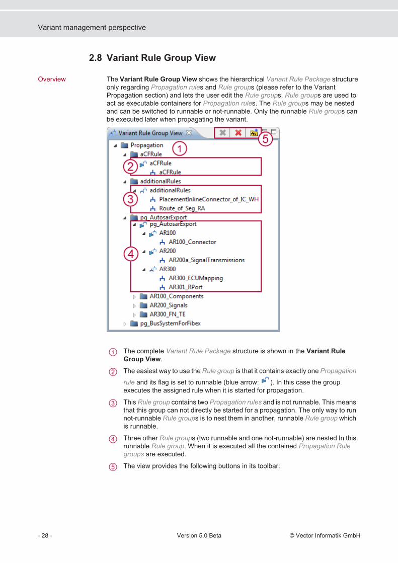
The Variant Rule Group View shows the hierarchical Variant Rule Package structureonly regarding Propagation rules and Rule groups (please refer to the VariantPropagation section) and lets the user edit the Rule groups. Rule groups are used toact as executable containers for Propagation rules. The Rule groups may be nestedand can be switched to runnable or not-runnable. Only the runnable Rule groups canbe executed later when propagating the variant.
The complete Variant Rule Package structure is shown in the Variant RuleGroup View.
The easiest way to use the Rule group is that it contains exactly one Propagation
rule and its flag is set to runnable (blue arrow: ). In this case the groupexecutes the assigned rule when it is started for propagation.
This Rule group contains two Propagation rules and is not runnable. This meansthat this group can not directly be started for a propagation. The only way to runnot-runnable Rule groups is to nest them in another, runnable Rule group whichis runnable.
Three other Rule groups (two runnable and one not-runnable) are nested In thisrunnable Rule group. When it is executed all the contained Propagation Rulegroups are executed.
The view provides the following buttons in its toolbar:
2.8
Overview
Variant management perspective
- 28 - Version 5.0 Beta © Vector Informatik GmbH

Removes a reference between two Rule groups or between aPropagation rule and a Propagation Rule Group.
Deletes the selected object from the model.
Creates a new Rule group. This is available on a Variant RulePackage or on another Rule group. In the case that the creation isstarted on another Rule group the new group is directly nested in theselected Propagation Rule Group - but the new object is placed in theparent Variant Rule Package.
The view's shortcut menu is shown in the next figure. It contains the undo/redo actionsas well as the same actions that can be found in the view's toolbar. The menu alsocontains an item that can be used to switch a Propagation group's runnable flag.
> Variant management perspective> Variant management concepts> Working with the variant diagram> Variant preferences
Shortcut menu
Further information
Variant management perspective
© Vector Informatik GmbH Version 5.0 Beta - 29 -

Variant management perspective
- 30 - Version 5.0 Beta © Vector Informatik GmbH

Variant preferences
Activates the Change Active Variant dialog that advises the user that it maytakes some time if you switch the variant while diagrams are open.
Considers not only the options set by active checkboxes. Considers also optionsthat are defined by propagation rules.
Deactivates the standard highlighting, e.g. if a highlighting rule is defined andthe standard isn’t needed any more.
Activates a preview of a wanted propagation.
If the standard functions are not enough Rule Groups may be defined andchosen to be used for highlighting and propagation.
Limits the propagation iterations for avoiding infinite loops.
Model artifacts that are visualized in diagrams have a transparent appearance if theyare not included in the active Variant. The transparency level can be adjusted usingthe Preferences. Select the category PREEvision | Highlighting and open the groupCommon Highlights in order to activate or deactivate the variant highlight and to setthe transparency level (Alpha Channel).
Preferences Dialogfor variantmanagement
Transparency invariants
Variant preferences
© Vector Informatik GmbH Version 5.0 Beta - 31 -

Note: Transparent objects are not selectable if the boundary for selectable transparentobjects prevents it (see Highlight Dependent Object Selection).
Variant preferences
- 32 - Version 5.0 Beta © Vector Informatik GmbH

The variant management example
To illustrate the concepts and the doing a simple example is used. The exampleincludes the Product Line Vector with a Hardware Architecture layer and an explicitvariant model.
Not all possible subsets of a Product Line make sense. In the Hexagon example thevariants have to fulfill the following constrains:> Diesel ECU and Gasoline ECU exclude each other.> ABS ECU and ESP ECU exclude each other.> Automatic transmission and manual transmission. Therefore the Transmission
ECU is optional.> Instrument Cluster is always part of a variant (also known as base content or
mandatory content).
The example also shows how different hardware equipment optional may be modeled:> Climate Control> Navigation System> Cell PhoneThese variant constraints are specified in PREEvision by a variant model (also knownas concept model or feature model). How to model such a variant is described in thenext chapters.
Description
Constrains
The variant management example
© Vector Informatik GmbH Version 5.0 Beta - 33 -
The variant management example
- 34 - Version 5.0 Beta © Vector Informatik GmbH

Step 1: Creating a variant model
For variant modeling the Variant Management perspective is available.
Variant models are stored in a separate layer Variant Package in a Product Line.
The description how to use the variant management is based on an example. You canread the single chapters stand-alone, but you will get a better understanding if youknow what is really done.
You can model variants via creating all artifacts manually, or you can use a wizard thatsupports you creating a variant structure. In the following steps the creation via wizardis described.1. Switch into the Variant Management perspective
(toolbar icon ).2. Open the shortcut menu on a Variant Package and select New | Variant
Structure….The Create Variant Structure wizard is opened.
3. Select a radio button to enter a new Concept Space or to use an existing one andcontinue with [Next >].
4. Press the [+] to add a Concept Template.Each Concept Template to be created is described in one row.
5. Enter the number of Alternatives and Sets for the Concept Template and select theVariant Package, in which the artifacts shall be created.
Variant Perspective
Variants in the ModelView
The example
Creating a variantStructure
Step 1: Creating a variant model
© Vector Informatik GmbH Version 5.0 Beta - 35 -

6. Continue with [Next >].7. Choose the number of how many Architecture Variants shall be created.8. Press [Finish] and the variant model structure will be created.
Now you have modeled a technical concept bundle (Concept Space) with itstechnical implementation possibilities (Concept Templates and its Alternatives).Also Architecture Variants are built but the content is not defined yet. You havealso provided a basis for the connection of the variant model with the E/E model(Sets). The Sets are not assigned to a template and have no assigned technicalmodel artifacts.
Note: If you want to structure your variant artifacts with folders you have to createthem manually before you run the wizard. The wizard doesn’t create the folders.Alternatively you can move the created artifacts in a later step into a packagestructure.
Note: The wizard does not only create the artifacts. It also creates the assignmentbetween the artifacts. So it assigns the Concept Templates and the ArchitectureVariants to the Concept Space. The assignment of the Alternatives to the ConceptTemplates must be done manually, e.g. after the renaming step.
> Renaming Alternatives, Architecture Variants, Sets> Defining feature concepts> Defining the specific variant combinations
After the initial variant structure is created, it is useful to rename the artifacts with namesaccording to their meaning, e.g.:
Next steps
Renaming theartifacts
Step 1: Creating a variant model
- 36 - Version 5.0 Beta © Vector Informatik GmbH
Step 2: Creating feature concepts for the variant
Equipment Template artifacts are created in the Model View in a Variant Package viashortcut menu.
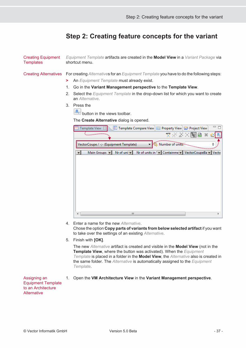
For creating Alternatives for an Equipment Template you have to do the following steps:> An Equipment Template must already exist.1. Go in the Variant Management perspective to the Template View.2. Select the Equipment Template in the drop-down list for which you want to create
an Alternative.3. Press the
button in the views toolbar.The Create Alternative dialog is opened.
4. Enter a name for the new Alternative.Chose the option Copy parts of variants from below selected artifact if you wantto take over the settings of an existing Alternative.
5. Finish with [OK].The new Alternative artifact is created and visible in the Model View (not in theTemplate View, where the button was activated). When the EquipmentTemplate is placed in a folder in the Model View, the Alternative also is created inthe same folder. The Alternative is automatically assigned to the EquipmentTemplate.
1. Open the VM Architecture View in the Variant Management perspective.
Creating EquipmentTemplates
Creating Alternatives
Assigning anEquipment Templateto an ArchitectureAlternative
Step 2: Creating feature concepts for the variant
© Vector Informatik GmbH Version 5.0 Beta - 37 -

2. Select the Architecture Variant in the drop-down list to which you want to assignthe Equipment Template Alternative.
3. Select an Alternative option in the Equipment Template area.
Note: In the Equipment Template area all existing Equipment Templates in the toplevel Variant Package are listed.
1. Open the Template View in the Variant Management perspective.2. Select the Equipment Template in the drop-down list to which you want to assign
Customer Features ( ).3. Drag the Customer Features from the Model View and drop them into the
Template View ( ).4. Activate the checkboxes to define which features should be available in which
Architecture Variant ( ).
The rows represent the amount of available equipment (in the majority of cases bythe use of Customer Features/- Sets). The columns represent the equipmentcombination. If the Containment column is checked the features belongs to thestandard equipment of a vehicle (or product).
Assigning Features tothe EquipmentTemplate
Step 2: Creating feature concepts for the variant
- 38 - Version 5.0 Beta © Vector Informatik GmbH
Note: Only Customer Features and Customer Feature Sets can be assigned toEquipment Templates but no Requirements because the Equipment Templatesrepresent the available customer observable features of a vehicle. Also Sets canbe assinged to Equipment Templates.
Note: It possible to make consistency checks for an Equipment Template and itsassigned features. For example: the coverage of all features through a technicalimplementation.
Step 2: Creating feature concepts for the variant
© Vector Informatik GmbH Version 5.0 Beta - 39 -

Step 2: Creating feature concepts for the variant
- 40 - Version 5.0 Beta © Vector Informatik GmbH

Step 3: Defining variant configurations
In this step the variant structure is already created by the wizard. Now, ArchitectureVariant combinations have to be created that makes sense.
1. Select the Architecture Variant in the drop-down list for that you want assigned its
content ( ).2. Select the Concept Template Alternatives in the drop-down lists to define them as
content of the Architecture Variant ( ).3.
Choose one Equipment Template Alternative option ( ).Now, you have defined that the 100 % Architecture VariantVectorCoupeBasicA that contains the Alternatives ABS, Automatic and Diesel.It is based on the Equipment Template VectorCoupeBasic.
Defining theArchitecture Variant
Step 3: Defining variant configurations
© Vector Informatik GmbH Version 5.0 Beta - 41 -

Variant permutation
There are a lot of possible Architecture Variants if all variant options are combined. Inthe example there are three Architecture Variants each with two Alternatives. The resultis 23 = 8 permutations (see table below).
In the most cases it doesn’t make sense to create all possible Architecture Variants. Inthis case the wizard supports the manual definition of the number how manyArchitecture Variants shall be created.
> Step 3: Defining variant configurations> Variant management concepts> Step 4: Connecting the variant model with the E/E model
7.1
Variant permutationinformation
Further information
Step 3: Defining variant configurations
- 42 - Version 5.0 Beta © Vector Informatik GmbH
Refining variants
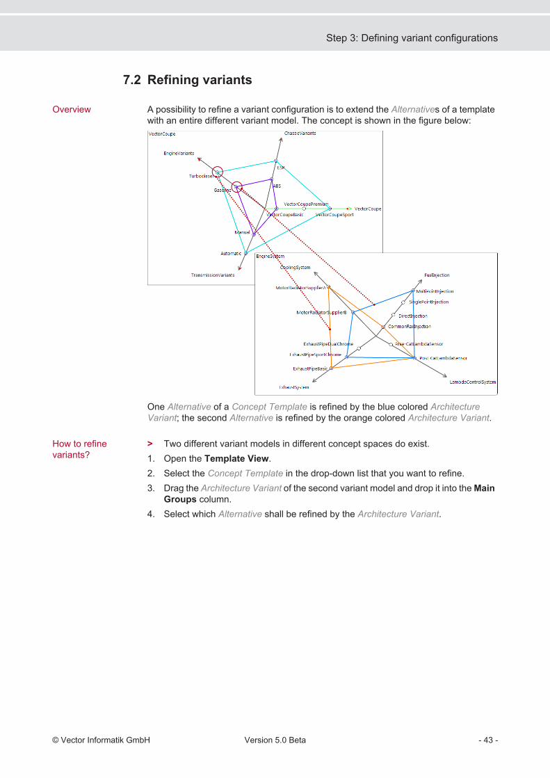
A possibility to refine a variant configuration is to extend the Alternatives of a templatewith an entire different variant model. The concept is shown in the figure below:
One Alternative of a Concept Template is refined by the blue colored ArchitectureVariant; the second Alternative is refined by the orange colored Architecture Variant.
> Two different variant models in different concept spaces do exist.1. Open the Template View.2. Select the Concept Template in the drop-down list that you want to refine.3. Drag the Architecture Variant of the second variant model and drop it into the Main
Groups column.4. Select which Alternative shall be refined by the Architecture Variant.
7.2
Overview
How to refinevariants?
Step 3: Defining variant configurations
© Vector Informatik GmbH Version 5.0 Beta - 43 -

Step 3: Defining variant configurations
- 44 - Version 5.0 Beta © Vector Informatik GmbH

Step 4: Connecting the variant model with the E/Emodel
The variant model is completed now. But there are no relations to the technicalhardware model defined, yet: e.g. to the Hardware Architecture layer. This relation canbe created by using Sets.With the help of Sets you can group artifacts that always are used together. For instanceyou can group all hardware artifacts that belong to one function e.g. like theTubodieselEngine in the figure below.To assign artifacts of the E/E model to a specific Architecture Variant you first have toadd the hardware artifacts to a Set and then assign the Set to one or several templates.
1. Open the Set Content View.2. Select the Set in the drop-down list you want to define content for.3. Go to the Model View and drag and drop all necessary artifacts into the Set
Content View.
4. If necessary change the Mode via double click (the default is the green in forincluded).
Note: Alternatively you can select the artifacts in e.g. a Network Diagram and press<F10> to add them to the Set.
When you select the Set in the Model View and e.g. the Network Diagram is opened,from that some artifacts are content of the Set these artifacts are highlighted then inthe diagram.
Overview
Defining Set content
Highlighting Setcontent
Step 4: Connecting the variant model with the E/E model
© Vector Informatik GmbH Version 5.0 Beta - 45 -

1. Open the Template View.2. Select the template in the drop-down list to that you want to assign a Set.3. Drag one or several Sets in the Model View and drop them into the Template
View ( ).
4. Activate the checkboxes for the Alternatives which should be active for which Set
for the active template ( ).
Creating relationbetween a Set and atemplate
Step 4: Connecting the variant model with the E/E model
- 46 - Version 5.0 Beta © Vector Informatik GmbH
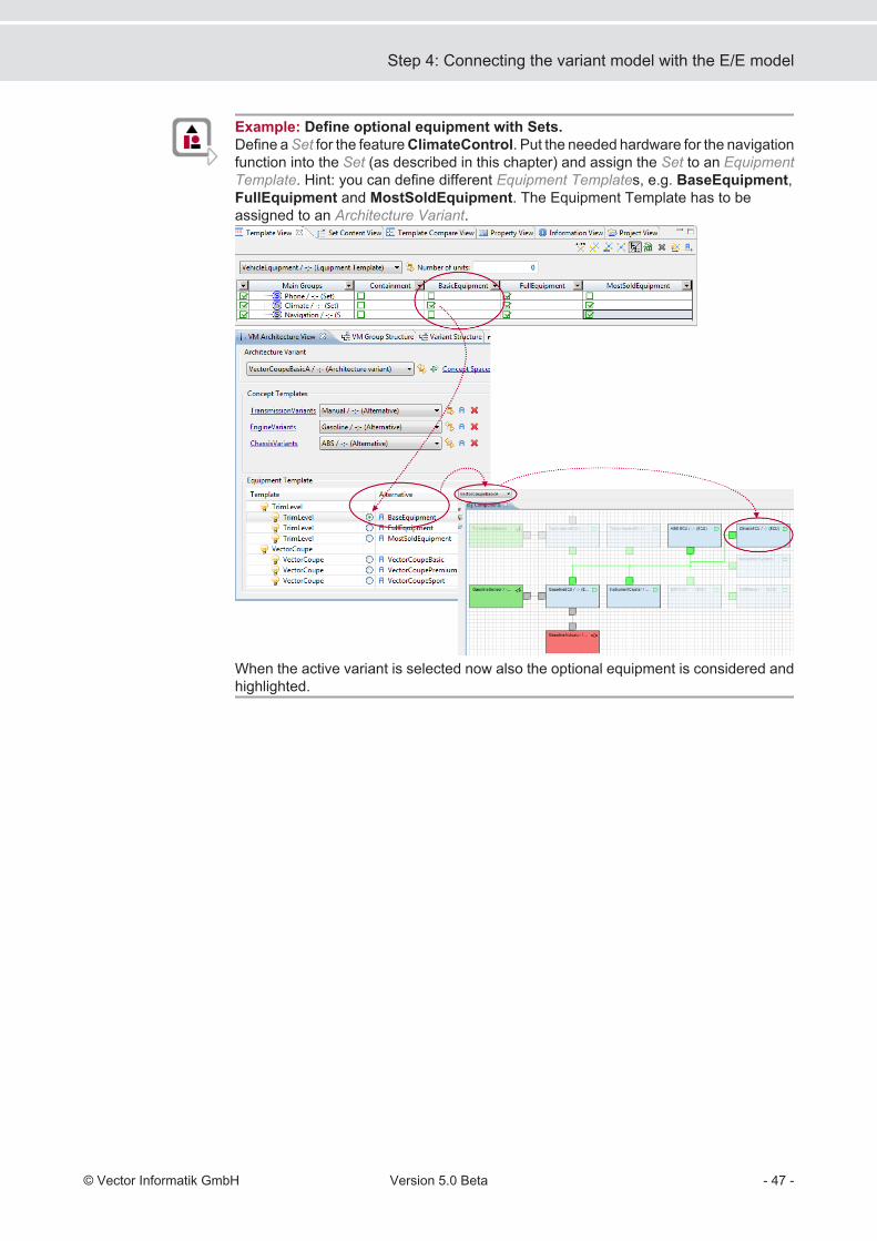
Example: Define optional equipment with Sets.Define a Set for the feature ClimateControl. Put the needed hardware for the navigationfunction into the Set (as described in this chapter) and assign the Set to an EquipmentTemplate. Hint: you can define different Equipment Templates, e.g. BaseEquipment,FullEquipment and MostSoldEquipment. The Equipment Template has to beassigned to an Architecture Variant.
When the active variant is selected now also the optional equipment is considered andhighlighted.
Step 4: Connecting the variant model with the E/E model
© Vector Informatik GmbH Version 5.0 Beta - 47 -

Step 4: Connecting the variant model with the E/E model
- 48 - Version 5.0 Beta © Vector Informatik GmbH

Step 5: Creating variant conditions
Conditions for variants can be modeled in different ways and for different use cases.
The creation of conditions in the Variant Diagram is explained with the example ofCustomer Features:1. Navigate in the Model View to Product Line | Variant Package.2. Create a Variant Diagram via shortcut menu in the Variant Package of your own
choice.3. Open the diagram by double click.4. Drag the existing Customer Features from the Model View (Product Line |
Product Goal | Customer Features) and drop them into the diagram.5. Create the Variant Condition via Palette or pop-up bar.6. Create the Variant Condition Assignment.
Conditions between Customer Features can especially be created in a predefinedtable.> A predefined table must already exist (Customer Feature Package | Available
Tables | CustomerFeatureConditions).1. Open the table via double click.2. Press in the Condition columns the <+> key.3. Double click in the drop-down list and select the condition you want to model for
the Customer Feature.
4. Press in the ObjectFeature column the <SPACE> key and select the targetCustomer Feature in the drop-down list that is affected by the condition.
A further way to create conditions is State Definitions and guards. State Definitions areavailable for Customer Features, guards may be used for State Values and VariantConditions.1. Navigate in the Model View to Product Goal | Customer Features.
Conditions forFeatures
Creating conditions inVariant Diagram
Creating conditions inCustomer Featuretable
Creating conditionswith State Definitions
Step 5: Creating variant conditions
© Vector Informatik GmbH Version 5.0 Beta - 49 -

2. Create a State Definition via shortcut menu New | State Definition on a CustomerFeature.
3. Create a State Value via shortcut menu on a State Definition.The name of the State Value equates the value itself.
4. Go to the Property View | General of the State Value.5. Insert the condition as Boolean value into the Guard field.
E.g. cf{“name”}.is{“4”}. Example:
6. For using the State Definition in variants drag the State Values in the ModelView and drop them into the Set Content View.
7. Go to the Template View and select in which Alternative the State Value shall beavailable.
The State Values that are not available for an Alternative are grayed out. So youget a good overview about the containments in a variant.
Note: Guards are also available for Variant Conditions.
Step 5: Creating variant conditions
- 50 - Version 5.0 Beta © Vector Informatik GmbH

xor One of the artifacts must be an exclusive part of the current variant.
or One either the other must be part of the variant.
and All artifacts must occur together.
trace This directed connection refers to another artifact that explains thecurrent artifact. So dependencies can be reconstructed.
req This directed connection refers to one or several other artifactswhich, if the current artifact is part of a variant, should also be partof this variant.
reqOr This directed connection refers to n other artifacts, from which atleast one must be part of the same variant as the artifact from thatthe connection is outgoing.
reqXor This directed connection refers to n other artifacts, from whichexact one must be part of the same variant as the artifact fromwhich the connection is outgoing.
exclude This directed connection refers to n other artifacts, from thatneither should be part in the same variant as the artifact from whichthe connection is outgoing.
mayUse A usage is advised.
equals The artifacts describe semantically the same circumstances.
optional The artifacts could take part in the model or not. If not there wouldnot be a semantically false model. Often used: Optional withrequires.
simplifies Through the selection of the amount of artifacts a simplification ofthe purpose artifact is estimated, based on the synergy effect.
complicates Through the selection of the artifacts amount a increase ofcomplexity is estimated for the realization of the purpose artifact.
triggers A cascading causal chain is triggered by an event and performedby a fulfiller.
Common conditions
Step 5: Creating variant conditions
© Vector Informatik GmbH Version 5.0 Beta - 51 -
About guards
A guard is a logical expression over features and their State Value or Condition. Guardsare used for defining conditions between Customer Features. They are evaluatedduring the variant configuration. They enabled or disable to features associated StateValues or Conditions.
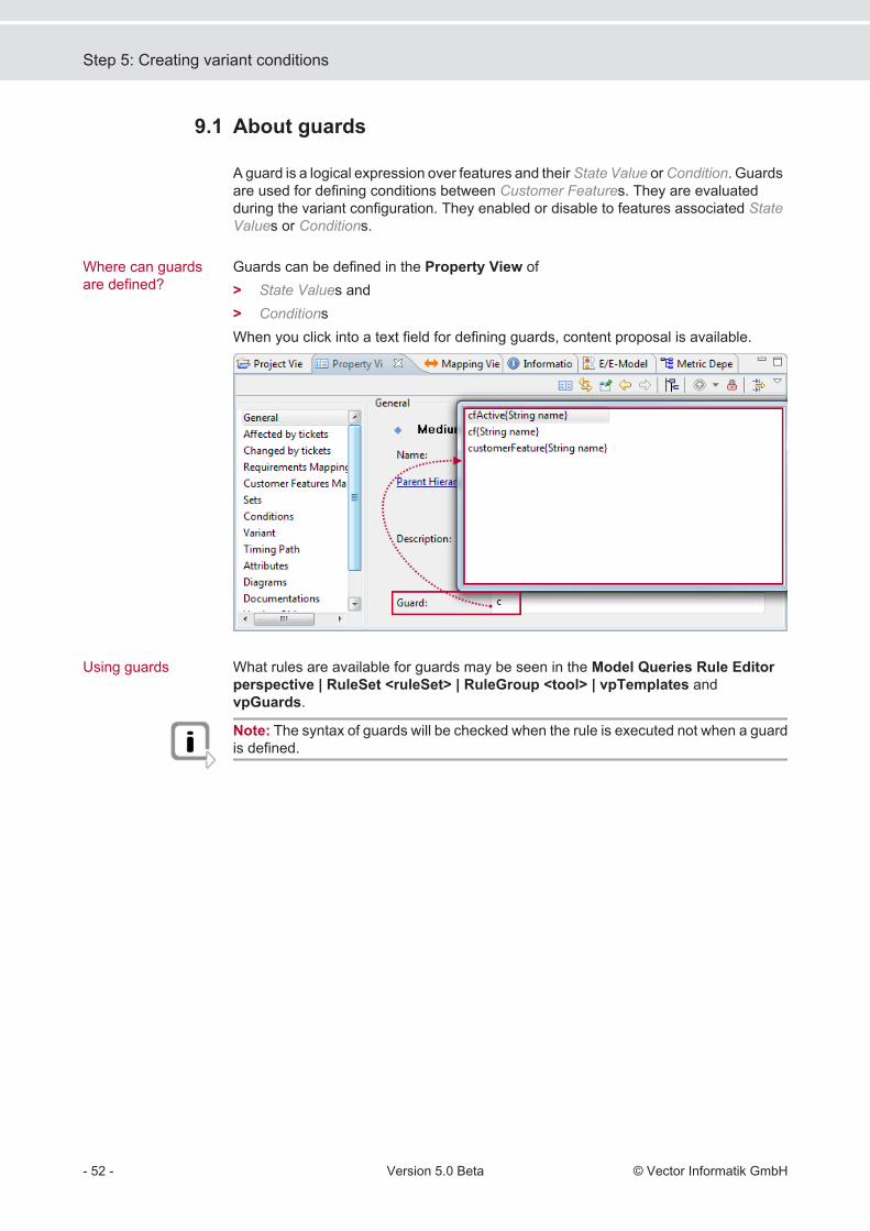
Guards can be defined in the Property View of> State Values and> ConditionsWhen you click into a text field for defining guards, content proposal is available.
What rules are available for guards may be seen in the Model Queries Rule Editorperspective | RuleSet <ruleSet> | RuleGroup <tool> | vpTemplates andvpGuards.
Note: The syntax of guards will be checked when the rule is executed not when a guardis defined.
9.1
Where can guardsare defined?
Using guards
Step 5: Creating variant conditions
- 52 - Version 5.0 Beta © Vector Informatik GmbH

Operation Return value Descriptioncf{“fname“} MCustomerFeature The operation returns a
feature object (instanceof theMCustomerFeatureclass) that has thegiven feature name“fname”. If such afeature does not exist anerror message isissued.
cfActive{“fname“} boolean The operation returnstrue, if a feature objectidentified by the givenname “fname” isincluded in the activevariant configuration. Ifsuch a feature does notexist an error messageis issued and false isreturned.
cf{“fname“}.is{“val“} boolean The operation returnstrue, if a feature objectidentified by the givenname “fname” has astate definition whosestate value equals to“val” within the activevariant configuration.Otherwise false isreturned.
cf{“fname“}.stateInt{} integer The operation returnsan integer numberrepresenting the currentstate value of thefeature object identifiedby the given name“fname” within theactive variantconfiguration. If thevalue can not beacquired an errormessage is issued and-1 is returned.
Operation overview
Step 5: Creating variant conditions
© Vector Informatik GmbH Version 5.0 Beta - 53 -

Operation Return value Descriptioncf{“fname“}.stateString{} String The operation returns a
string valuerepresenting the currentstate value of thefeature object identifiedby the given name“fname” within theactive variantconfiguration. If thevalue can not beacquired an errormessage is issued and“” (empty string) isreturned.
attributeInt{”attrDefName”, customerFeature}
The operation returnsan integer number of therequired feature objectattribute identified bythe givenname ”attrDefName”. If no attribute is foundor several attributes withthe same name areexisting an errormassage is issued and-1 is returned.
attributeString{”attrDefName”, customerFeature}
The operation returns astring value of therequired feature objectattribute identified bythe givenname ”attrDefName”. If no attribute is foundor several attributes withthe same name areexisting an errormassage is issued and“” (empty string) isreturned.
Operator Description! Logical NOT
&& Logical AND
|| Logical OR
> / < / >= / <= Comparison operators:greater than / less than / greater or equal than / less or equalthan
Operators for guards
Step 5: Creating variant conditions
- 54 - Version 5.0 Beta © Vector Informatik GmbH

Operator Description== Comparison operator:
equals
!= Comparison operator:is not equal
Step 5: Creating variant conditions
© Vector Informatik GmbH Version 5.0 Beta - 55 -

Step 5: Creating variant conditions
- 56 - Version 5.0 Beta © Vector Informatik GmbH

Step 6: Using of variants
The variant model is finished. How to use the variant management is described in thenext chapters.
1. Go to the PREEvision Standard perspective.2. Select the variant to be active in the drop-down list on the toolbar.
The artifacts that are part of the active variant are highlighted in the diagram.The artifacts that are not part of the active variant are faded out and are marked inthe Model View with a blue exclamation mark ( ).
But there is the mandatory content missing that is contained in several variantssimilarly. It is not very efficient to assign the same artifacts a few times to variants.
By right clicking the drop-down list the offered variant entries can be limited. When afilter is active the drop-down list has another color.
> Regular Expression may be entered to filter the shown elements.Further the shown elements' type can be restricted to one of the shown types.
Overview
Activating variant andvisualize thedifference
Filter options
Step 6: Using of variants
© Vector Informatik GmbH Version 5.0 Beta - 57 -
> If a regular expression should be used, a dialog asks for the regular expression touse as shown in the next figure. Refer to the section on Regular Expressions formore information on creating a filter.
> Filter Architecture VariantsThe background is colored orange.
> Filter Concept TemplatesThe background is colored purple.
> Filter Equipment TemplatesThe background is colored dark yellow.
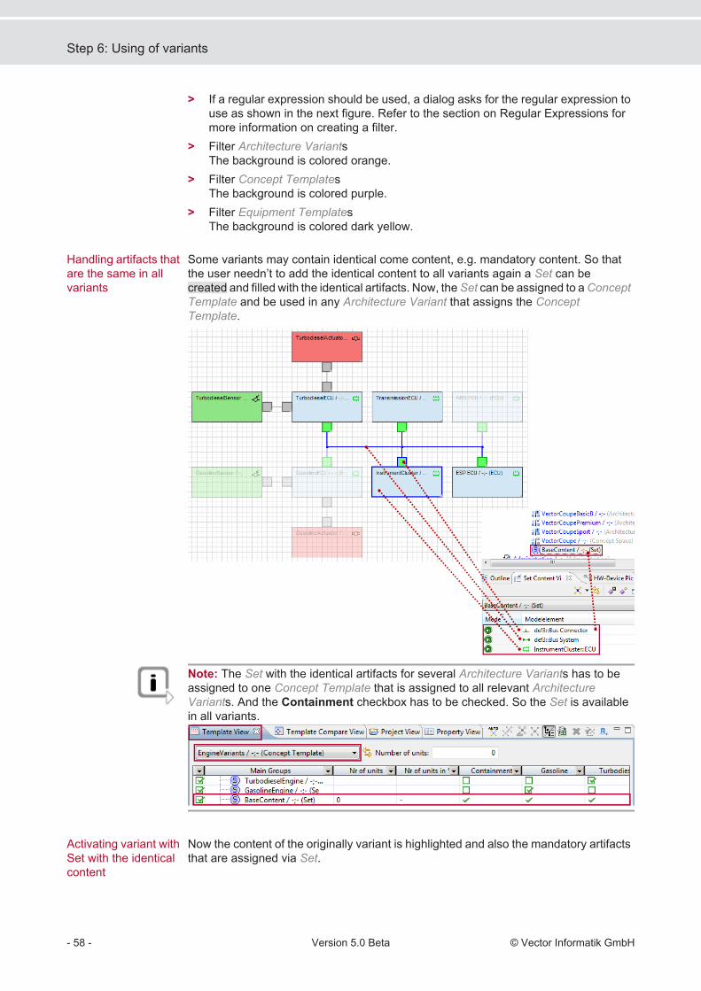
Some variants may contain identical come content, e.g. mandatory content. So thatthe user needn’t to add the identical content to all variants again a Set can becreated and filled with the identical artifacts. Now, the Set can be assigned to a ConceptTemplate and be used in any Architecture Variant that assigns the ConceptTemplate.
Note: The Set with the identical artifacts for several Architecture Variants has to beassigned to one Concept Template that is assigned to all relevant ArchitectureVariants. And the Containment checkbox has to be checked. So the Set is availablein all variants.
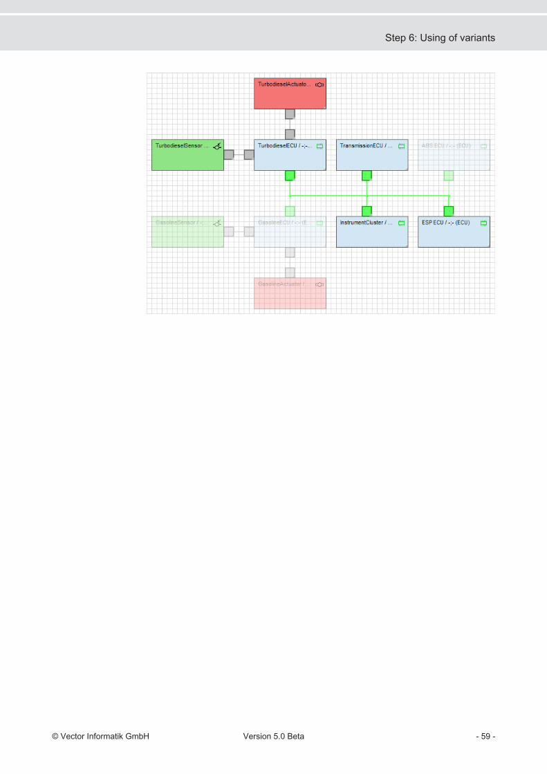
Now the content of the originally variant is highlighted and also the mandatory artifactsthat are assigned via Set.
Handling artifacts thatare the same in allvariants
Activating variant withSet with the identicalcontent
Step 6: Using of variants
- 58 - Version 5.0 Beta © Vector Informatik GmbH
Step 6: Using of variants
© Vector Informatik GmbH Version 5.0 Beta - 59 -

Step 6: Using of variants
- 60 - Version 5.0 Beta © Vector Informatik GmbH

Working with the variant diagram
One possibility to display an overview of a Concept Space with its context is the VariantDiagram.
The box represents the Concept Space. The Concept Templates are shown as blackarrows and its Alternatives as dots on the arrow. The Equipment Template is shownas green arrow and its Alternatives also as dots on the arrow. The ArchitectureVariant is represented by the spider web connecting the Alternatives of one EquipmentTemplate and several Concept Templates to one valid 100% composition of the 150%model.
> A variant model already exists in the Model View.1. Create a Variant Diagram in the Model View inside a Variant Package (shortcut
menu New | Variant Diagram…).2. Open the diagram via double click.3. Drag the Concept Space artifact from the Model View and drop it into the diagram.4. Drag and drop also the Alternatives to the corresponding Concept Template.5. Drag and drop the Equipment Template and its Alternatives to the diagram.6. At least drag and drop the Architecture Variants to the diagram.
A variant model also can be created with the Variant Diagram.1. Open the Variant Management perspective.2. First create a Variant Diagram in the Model View (shortcut menu New | Variant
Diagram…).3. Open the diagram with double click.4. Create the artifacts in the following sequence via Palette or pop up bar:
> Concept Space> Equipment Template> Equipment Template Alternative> Concept Template> Concept Template Alternative
Introduction
How to create aVariant Diagram?
Working with the variant diagram
© Vector Informatik GmbH Version 5.0 Beta - 61 -

> Architecture Variant5. Place the Architecture Variant on one Equipment Template Alternative.
6. Go to the VM Architecture View and assign the Concept Template Alternativesvia drop down list to the Architecture Variant.
The new Architecture Variant that was created in the Variant Diagram must beselected.
The created Concept Template Alternatives are available and can be selected.
The Equipment Template Alternative is already selected in the VariantDiagram.
Working with the variant diagram
- 62 - Version 5.0 Beta © Vector Informatik GmbH

In the Variant Diagram also conditions for dependencies between artifacts can bemodeled.
Variant Condition defines a dependency between two artifacts. There aredifferent conditions that can be chosen, e.g. XOR, AND, EXCLUDE.
Variant Condition Assignment connects the Variant Condition with an artifact.Naturally two Variant Condition Assignments must be created to connect twoartifacts. It is an undirected condition and does the condition apply from oneartifact to the other and vice versa.
Directed Variant Condition Assignment also connects the condition with anartifact, but the direction is important.
The Palette elementsfor the variantmanagement
Create conditions byVariant Diagram
Working with the variant diagram
© Vector Informatik GmbH Version 5.0 Beta - 63 -

Working with the variant diagram
- 64 - Version 5.0 Beta © Vector Informatik GmbH

Using parameters variant specific
It is possible to define variant specific parameters and parameter values.
Creating differentparameter fordifferent variants
Using parameters variant specific
© Vector Informatik GmbH Version 5.0 Beta - 65 -
Using parameters variant specific
- 66 - Version 5.0 Beta © Vector Informatik GmbH

Propagating variants
The manual assignment of artifacts for setting up a variant is very time intensive andthe method is prone to making mistakes. To master the situation PREEvision providesa rule based variant propagation. The starting point for propagation is a Set withmanually added artifacts. According to the selected rules used by the propagationdifferent artifacts are automatically included as result: ports, mappings, mappedartifacts, etc.
Caution: Keep in mind that artifacts in a variant are always related to each other andalso to artifacts outside a variant. Sometimes there must be made decisions, e.g. whenexisting ambiguous mappings between artifacts. Also it may happen that the inclusionof an artifact can often be derived by the inclusion of conditioned artifacts. Submit suchdependencies to a careful examination.
> Automatically adding artifacts to active variants.> Definition of variant content
> Manual selection> System integration
> Content-based> What is included> What needs to be included
> Iterative> Adding artifacts> Checking content again.
There are Logical Functions mapped to Application SW Components. Now, the onlythe Logical Functions are assigned to a variant. The remaining artifacts shall be addedto the variant by propagation.
Why propagatingvariants?
Supported functions:
Example for variantpropagation
Propagating variants
© Vector Informatik GmbH Version 5.0 Beta - 67 -

The next steps show how to create a Propagation Rule. The rule adds the mappingartifacts of the source artifacts (here: Logical Functions) and the correspondingmapping target (here: Application SW Components).> The source artifacts need to be contained in a variant Set (add artifact with <F10>
to the Set). The Set need to be part of the corresponding variant.
1. Activate the Propagation Rule Editor perspective.
2. When no rules are displayed in the Propagation Rule Model View, load the
propagation rules by pressing the toolbar button .3. Create a RuleGroup in the Propagation Rule Editor perspective | Project |
RuleModel | RuleSet.4. Create a Propagation Rule inside the RuleGroup via shortcut menu New | Rules
| Propagation Rule.5. Double click the new Rule to open it in a diagram.
Propagating variants
- 68 - Version 5.0 Beta © Vector Informatik GmbH
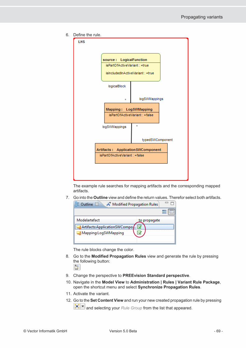
6. Define the rule.
The example rule searches for mapping artifacts and the corresponding mappedartifacts.
7. Go into the Outline view and define the return values. Therefor select both artifacts.
The rule blocks change the color.8. Go to the Modified Propagation Rules view and generate the rule by pressing
the following button:
9. Change the perspective to PREEvision Standard perspective.10. Navigate in the Model View to Administration | Rules | Variant Rule Package,
open the shortcut menu and select Synchronize Propagation Rules.11. Activate the variant.12. Go to the Set Content View and run your new created propagation rule by pressing
and selecting your Rule Group from the list that appeared.
Propagating variants
© Vector Informatik GmbH Version 5.0 Beta - 69 -

Only start the propagation if a variant is active.13. Select a container artifact of the variant management where the propagated
artifacts shall be placed.
It is recommended to choose different, e.g. Sets for the artifacts on that thepropagation is started and the result artifacts of the propagation.The Set in which the propagated artifacts shall be placed need to be a part of theactive variant!
14. Start the propagation with [OK].The result of the propagation is shown in the figure below:
Note: The propagation rule runs as long as every matching artifact is found that belongsto current active variant.
Propagating variants
- 70 - Version 5.0 Beta © Vector Informatik GmbH

Index
PPerspectives
Variant management 11
Preferences Variant management 31
VVariant management
Alternative 7Architecture Variant 8, 41Artifact overview 7Concept Space 7Concept Template 7Concepts 5Conditions 63Creating a variant structure 35Creating ArchitectureVariants
35
Creating ConceptTemplates
35
Creating EquipmentTemplates
37
Creating Sets 45Creating Variant Diagram 61Description of variantmodel
9
Equipment Template 7, 37Example 33Highlighting 45, 57
Parameters 65Perspective - Set ContentView
24
Perspective - TemplateCompare View
27
Perspective - TemplateView
21
Perspective - Variant RuleGroup View
28
Perspective - VariantStructure
19
Perspective - VMArchitecture View
14
Perspective - VM GroupStructure
16
Perspective - VMPropagation Rule Preview
20
Preferences 31Propagation 67Set 8, 45Use cases 5Variant conditions 49Variant Diagram 61Variant managementperspective
11
Variant Managementperspective
35
Variant managementwizard
35
Variant permutation 42
Index
© Vector Informatik GmbH Version 5.0 Beta - 71 -

Index
- 72 - Version 5.0 Beta © Vector Informatik GmbH


Get more Information!
Visit our Website for:
> News
> Products
> Demo Software
> Support
> Training Classes
> Addresses
www.vector.com