prefailure and failure mechanics of the porcine ascending
TRANSCRIPT

Sachin B. ShahDepartment of Biomedical Engineering,
University of Minnesota,
Minneapolis, MN 55455
e-mail: [email protected]
Colleen WitzenburgDepartment of Mechanical Engineering,
University of Minnesota,
Minneapolis, MN 55455
e-mail: [email protected]
Mohammad F. HadiDepartment of Biomedical Engineering,
University of Minnesota,
Minneapolis, MN 55455
e-mail: [email protected]
Hallie P. WagnerDepartment of Biomedical Engineering,
University of Minnesota,
Minneapolis, MN 55455
e-mail: [email protected]
Janna M. GoodrichDepartment of Biomedical Engineering,
University of Minnesota,
Minneapolis, MN 55455
e-mail: [email protected]
Patrick W. AlfordDepartment of Biomedical Engineering,
University of Minnesota,
Minneapolis, MN 55455
e-mail: [email protected]
Victor H. Barocas1
Department of Biomedical Engineering,
University of Minnesota,
Minneapolis, MN 55455
e-mail: [email protected]
Prefailure and FailureMechanics of the PorcineAscending Thoracic Aorta:Experiments and a MultiscaleModelAscending thoracic aortic aneurysms (ATAA) have a high propensity for dissection,which occurs when the hemodynamic load exceeds the mechanical strength of the aorticmedia. Despite our recognition of this essential fact, the complex architecture of themedia has made a predictive model of medial failure—even in the relatively simple caseof the healthy vessel—difficult to achieve. As a first step towards a general model ofATAA failure, we characterized the mechanical behavior of healthy ascending thoracicaorta (ATA) media using uniaxial stretch-to-failure in both circumferential (n¼ 11) andaxial (n¼ 11) orientations and equibiaxial extensions (n¼ 9). Both experiments demon-strated anisotropy, with higher tensile strength in the circumferential direction(2510 6 439.3 kPa) compared to the axial direction (750 6 102.6 kPa) for the uniaxialtests, and a ratio of 1.44 between the peak circumferential and axial loads in equibiaxialextension. Uniaxial tests for both orientations showed macroscopic tissue failure at astretch of 1.9. A multiscale computational model, consisting of a realistically alignedinterconnected fiber network in parallel with a neo-Hookean solid, was used to describethe data; failure was modeled at the fiber level, with an individual fiber failing whenstretched beyond a critical threshold. The best-fit model results were within the 95% con-fidence intervals for uniaxial and biaxial experiments, including both prefailure and fail-ure, and were consistent with properties of the components of the ATA media.[DOI: 10.1115/1.4026443]
Keywords: biomechanics, dissection, aneurysm, media, collagen, elastin
Introduction
ATAA are dilatations of the arterial wall that result primarilyfrom a weakening in the middle smooth muscle layer, or media,of the artery [1–3]. Aneurysm dissection and rupture pose seriousrisk of mortality and are the primary concerns for patients with anATAA [1–4]. Cystic medial degeneration (which can be causedby disease, injury, or hereditary condition [2,3]), weakens the aor-tic wall, allowing for the formation of aneurysms and subsequentdissections. Aneurysm growth and dissection is further driven byincreased hemodynamic loading within the media [5]. Ascendingaortic dissection, the most prominent failure mode, occurs whenthe hemodynamic stresses within the media exceed the capacity ofits collagen and elastin constituents allowing blood to pass intothe medial lamella and peel it apart (delaminate) [6]. Ultimately,this tear can propagate axially along the length of the aorta, eitherproximally or distally, and in the absence of clinical intervention,
may lead to further complications such as ischemia, aortic regur-gitation, cardiac tamponade, aortic rupture, and death [1].
Ascending aortic aneurysms have an incidence rate of 10.4 per100,000 person-years [7], with significant risk of dissection orrupture [7]. Clinically, ATAA management balances the risk ofaneurysm rupture with the risk of surgery-related complicationsand death [2,3]. Risk of rupture is correlated with aneurysm diam-eter [2,7]; aneurysms greater than 6 cm in diameter exhibit a sig-nificantly higher risk of rupture [2]. Thus, for patients withoutvalvular disorders, current guidelines indicate surgical interven-tion for ATAA diameters greater than 5.5 cm and monitoring forthose less than 5.5 cm [2].
In spite of clinical guidelines and what is known about thepathogenesis of aneurysms, dissection and rupture occur in a sig-nificant number of patients whose aneurysms are less than 5.5 cmin diameter [8], suggesting that a better understanding of the dis-section process is needed. Experimental studies have investigatedthe mechanical failure of aortic media [6,9,10], but only a few the-oretical models have attempted to emulate this response [11–13].The most notable work to date, by Gasser and Holzapfel [12],employs constitutive FE modeling with two independent continu-ous and cohesive zones to model the fiber network and groundmatrix, respectively. While the Gasser–Holzapfel model is
1Corresponding author.Contributed by the Bioengineering Division of ASME for publication in the
JOURNAL OF BIOMECHANICAL ENGINEERING. Manuscript received September 15, 2013;final manuscript received January 1, 2014; accepted manuscript posted January 8,2014; published online February 5, 2014. Editor: Beth Winkelstein.
Journal of Biomechanical Engineering FEBRUARY 2014, Vol. 136 / 021028-1Copyright VC 2014 by ASME
Downloaded From: http://asmedigitalcollection.asme.org/ on 11/11/2014 Terms of Use: http://asme.org/terms

capable of describing the mechanical behavior of the aorta, it failsto capture complex fiber-fiber and fiber-matrix interactions oraddress failure at the microscopic scale. A model employingmicroscale mechanics and structure to determine the macroscaleresponse would have potential to incorporate greater anatomicaldetail and could be applied to a broader range of conditions. Thiswork represents an initial attempt to apply such multiscale con-cepts to the mechanics of the ATA.
The objectives of this study were (1) to characterize the prefai-lure and failure response of healthy porcine ascending aorta tissueunder uniaxial and biaxial loading and (2) to describe thatresponse with a multiscale, FE damage model. The model hasbeen shown to be effective for prefailure and failure behavior ofcollagen gels [14] and has been applied to prefailure behavior ofdecellularized arterial wall [15].
Methods: Experiment
ATA from adolescent male swine (�6 months old,88 6 11.5 kg) were collected following in vivo atrial ablationstudies. Immediately upon harvesting, specimens were stored in1% phosphate-buffered saline solution (PBS) at 4 �C overnight.All experiments were performed within 24 h of tissue dissection.
A ring from the ascending aorta was cut distal to the aorticvalve and proximal to the brachiocephalic trunk (Fig. 1(a)). Thering was cut open at its superior edge to obtain a flat, rectangulartissue sample, and the intima, adipose tissue, and adventitia wereremoved (Fig. 1(b)). Then, the rectangular tissue specimen wascut into dog-bones (uniaxial) and/or cruciforms (biaxial), both ax-ially and circumferentially aligned, for mechanical testing. Sam-ples were immersed in 1% PBS at room temperature duringmechanical testing. Verhoeff’s stain was used to texture the lumi-nal surface of the media for optical displacement mapping(Figs. 1(c) and 1(d)). Once prepared, the sample was subjected touniaxial or biaxial testing.
Uniaxial Extension to Failure. Rectangular tissue strips(�20 mm� 5 mm) with the long axis in either the circumferential(CIRC) or axial (AXI) orientation were cut. A 5 mm circular bi-opsy punch was used to create a dog-bone shape (Fig. 1(c)). Sev-eral samples in both orientations were obtained from a singleaorta. Images of each sample were taken to determine its initialunloaded dimensions.
Mechanical testing was conducted on a computer-controlled,uniaxial testing machine (MTS, Eden Prairie, MN). Samples wereplaced in a custom rig. Samples were extended at a rate of 3 mm/min until failure, and force was measured using a 5 N load cell.
The deformation of the tissue’s luminal surface was recorded(�157 pixels/mm) at a rate of one image per 5 s.
The force measured was divided by the undeformed cross-sectional area at the failure point in the neck in order to calculatethe first Piola–Kirchhoff Stress. Image analysis and strain trackingwas performed per our previous studies (e.g., Ref. [16]) to deter-mine the local Green strain. Samples that did not fail in the neckregion of the dog-bone (�28% of samples) were not included inthe analysis. Peak tensile stress was evaluated at the point offailure.
Equibiaxial Extension. Biaxial samples were created by cut-ting a cruciform shape from an approximately square(�20� 20 mm) section of tissue such that the CIRC and AXIdirections remained parallel to the arms. An unloaded biaxial sam-ple is shown in Fig. 1(d).
The biaxial testing method was similar to that of previous stud-ies (e.g., Ref. [16]) with a slight preload (�0.1 N) applied to eachcruciform arm. Samples were loaded onto a biaxial tester (Instron,Norwood, MA) with four 5 N load cells using a custom rig. Eachsample was preconditioned with nine equibiaxial extensions to40% grip strain. Following preconditioning, an experimental equi-biaxial extension was performed at a strain rate of 3 mm/min to40% grip strain, a subfailure load in contrast to the failure loadingfor uniaxial samples. During this extension, images of the tissue’sspeckled luminal surface and the forces at each grip wererecorded.
Again, local Green strain was determined using image analysisand strain tracking per our previous studies [16]. Forces in theaxial and circumferential arms were divided by the respectiveundeformed cross-sectional areas in order to calculate the firstPiola–Kirchhoff stress.
Methods: Model
The multiscale model (Fig. 2, Refs. [14,15,17]) was made up ofelements at three scales: the finite element (FE) domain at themillimeter (mm) scale, representative volume elements (RVE) atthe micrometer (lm) scale, and the fibers with radii at the
Fig. 1 (a) Porcine aortic arch. Black dotted lines demarcateascending aortic ring. White star symbolizes a marker used tokeep track of tissue sample orientation. (b) Ascending aorticring with intima, adventitia, adipose, and loose connective tis-sue removed. Axial and circumferential directions shown withwhite arrows. (c) Undeformed, typical uniaxial sample in CIRCorientation with speckling prior to loading. Arrow indicates ori-entation and direction of pull. (d) Undeformed, typical biaxialsample with speckling prior to loading. Arrows indicate orienta-tion and direction of pull.
Fig. 2 Synopsis of multiscale model. Uniaxial or biaxial geo-metries are developed into millimeter sized finite elementmeshes. Each element consists of eight Gauss points that dic-tate its stress-strain response. Each Gauss point consists ofrepresentative volume elements (RVE) that consist of a nano-scale fiber network in parallel with a nearly incompressible neo-Hookean matrix. Deformation of the macroscale structurecauses the fiber network to stretch and reorient to reach forceequilibrium. Fibers that stretch beyond a critical value are con-sidered failed and their modulus of elasticity is reset to a near-zero value.
021028-2 / Vol. 136, FEBRUARY 2014 Transactions of the ASME
Downloaded From: http://asmedigitalcollection.asme.org/ on 11/11/2014 Terms of Use: http://asme.org/terms

nanometer (nm) scale. Each FE element contained eight Gausspoints, and each Gauss point was associated with an RVE. EachRVE was comprised of a discrete fiber network in parallel with anearly incompressible neo-Hookean component to represent thenonfibrous material (matrix) [15]. The matrix and fiber networkwere functionally independent, with the sole exception that fibernetwork failure dictated simultaneous matrix failure. Stressesdeveloped by the network and the matrix were additive (Table 1).Matrix material was considered homogenous throughout themodel; however, each element was assigned a unique set of fibernetworks, and new networks were generated for each iteration.
The macroscale and microscale stress and strain were coupledas described previously [18], and the corresponding governingequations are outlined in Table 1. In brief, displacements appliedto the macroscale model were passed down to individual RVEs.Pre-oriented Delaunay networks within the RVE stretched andrearranged in response to the displacements, generating net forceson the boundary network nodes. From these net forces, a volume-averaged stress was determined for each Gauss point within theelement. The macroscopic displacement field was updated untilthe overall Cauchy stress balance was satisfied. Rigid boundaryconditions were placed at the edges of the grip while the rest ofthe surface was free to move. Model simulations were run at theMinnesota Supercomputing Institute on 32-core parallel process-ors, with clock times averaging 4–6 h per simulation.
Model Specification and Parameter Estimation. Table 2summarizes the key parameters of the model. The orientation ofthe fiber network, which plays a critical role in the mechanicalresponse, was described by an orientation tensor X. The compo-nents of X correspond to the degree of alignment in the coordinatedirections, with the trace of X equal to 1 by construction (furtherdetails in Ref. [15]). Previous studies have shown that collagenfibers within the arterial media have strong preferential orientationin the circumferential direction (Xhh) while some percentage offibers are mainly oriented in the axial direction (Xzz) and evensmaller percentage in the radial direction (Xrr) [19–23]. Based onthose studies, the average orientation for collagen fiber networksin the media [Xhh Xzz] was extrapolated to be [0.62 0.37] [20].The initial network orientation tensor components [Xhh Xzz Xrr]were, therefore, specified to be [0.6, 0.3, 0.1] 6 [0.039, 0.040,0.006]—an orientation state close to that measured in Ref. [20]and with a small amount of alignment in the r direction to
maintain the integrity of the network. A single network was usedto represent the combined contribution of the collagen and elastincomponents, with a volume fraction of 5% [15]. Fiber radius wasset to 100 nm to replicate fiber geometry reported for elasticlamellae in arterial walls [24,25]. The matrix was modeled asnearly incompressible with a Poisson’s ratio, v, of 0.49.
Four model parameters—fiber small-strain Young’s modulusEf, critical fiber failure stretch kcrit, matrix shear modulus G, and anonlinear fitting parameter, ß—were regressed to the experimentaldata. The model was fit up to the maximum experimental stress,rupture and 40% strain, for uniaxial and biaxial experiments,respectively, while not including post rupture or unloading condi-tions. A value of 31.4 kPa was used as an initial guess and anupper bound for the matrix shear modulus based on the work ofHolzapfel [26]. Fitted parameters were chosen to minimize thetotal sum of squared error between the model and experimentalforce curves for both the uniaxial and biaxial configurations. Bothsimulations were repeated for ten iterations. Each iteration usedunique randomly selected networks that were generated using thesame network criteria, Table 1.
Statistical Analysis
Unless otherwise specified, all p-values were calculated usingunpaired two-tailed t-tests with Bonferroni correction and assum-ing equal variances (GraphPad Prism v. 5.03). A p-value less than0.05 was deemed significant. All values are reported as mean695% confidence intervals.
Results
Uniaxial Extension to Failure. Uniaxial samples from bothCIRC (n¼ 11) and AXI (n¼ 11) orientations were loaded to fail-ure. The stress-strain response was nonlinear, characteristic ofmany tissues (Fig. 3) [27]. As expected, anisotropic behavior wasobserved in the tensile strength of the tissue. Peak stress was sig-nificantly (p< 0.001) higher in the CIRC versus AXI orientation(Fig. 4(a); 2510 6 979 kPa versus 750 6 228 kPa). Model simula-tion results showed similar anisotropy (p< 0.001) (Fig. 4(a);2362 6 10.3 kPa versus 958 6 3.6 kPa) when using the parameters(Table 2) that were regressed to the combined uniaxial and biaxialdata sets. In comparing experimental and model results, no statis-tically significant difference in the CIRC direction (p¼ 0.74) was
Table 1 Governing equations applied within the model, as well as the scale at which each equation and its parameters are applied
Equation Description Scale Parameters
rij; j ¼1
V
þ@V
ðrLij � rijÞuk;jnkdS
Macroscale Volume-Averaged Stress Balance [16] Tissue r: macroscale averaged Cauchy stressV: RVE volume
rL: microscale stressu: RVE boundary displacement
n: normal vector to RVE boundary
rij ¼1
V
ðrL
ij dV ¼ 1
V
Xbc
xifjVolume-Averaged Stress of RVE [16] Network bc: boundary for all RVE cross links
x: boundary coordinatef: force acting on boundary
Ff ¼Ef Af
ßeßeG � 1� � Fiber Constitutive Equation [15,17–19] Fiber Ff: fiber force
and Ef � 0 when kf > kcrit Ef: Young’s modulus of fiber at infinitesimal strainAf: fiber cross-sectional area
eG: fiber Green strainß: fitting parameter for fiber nonlinearity
kf: fiber stretchkcrit: fiber stretch at failure
rmij ¼
G
JBij � dij
� �þ 2Gv
J 1� 2vð Þ dij ln Jð Þ Matrix Governing Equation [4] Matrix rM: matrix Cauchy stressG: shear modulus
J: deformation tensor determinantB: left Cauchy–Green deformation tensor
v: Poisson’s ratio
Journal of Biomechanical Engineering FEBRUARY 2014, Vol. 136 / 021028-3
Downloaded From: http://asmedigitalcollection.asme.org/ on 11/11/2014 Terms of Use: http://asme.org/terms

observed. For the AXI direction, the tensile strength predicted bythe model was within the 95% confidence interval for the experi-ments, but there was statistical significance (p¼ 0.046) due to thetighter confidence intervals for the model.
The media on the inner curvature of the arch is typically thickerthan the outer [28], likely because the vessel remodels to balancethe higher circumferential wall stresses caused by the curvature[29]. To verify that this remodeling does not affect the failuremechanics of the tissue, we compared the peak stress and strain ofsamples taken from the inner and outer curvature. Regional analy-sis found no significant difference in peak stress between uniaxialsamples taken from the interior versus exterior of the aortic archfor either the CIRC or AXI orientations (p-values ranged form0.10 to 0.28). No significant difference in peak stretch was
observed between interior and exterior AXI uniaxial samples;however, a significant difference (p¼ 0.04) was observed forCIRC uniaxial samples. Samples near the exterior of the archexhibited only 9.6% larger peak stretch than those from theinterior.
No significant difference was noted in experimental peakstretch between the CIRC and AXI directions (Fig. 4(b);1.99 6 0.07 versus 1.92 6 0.16, p¼ 0.36); however, model resultsbetween the two directions was significant (Fig. 4(b);1.98 6 0.003 versus 2.05 6 0.003, p< 0.001). In comparing theexperimental and model results, there was no statistically signifi-cant difference in peak stretch for either the CIRC (p¼ 0.74) orAXI (p¼ 0.07) orientation.
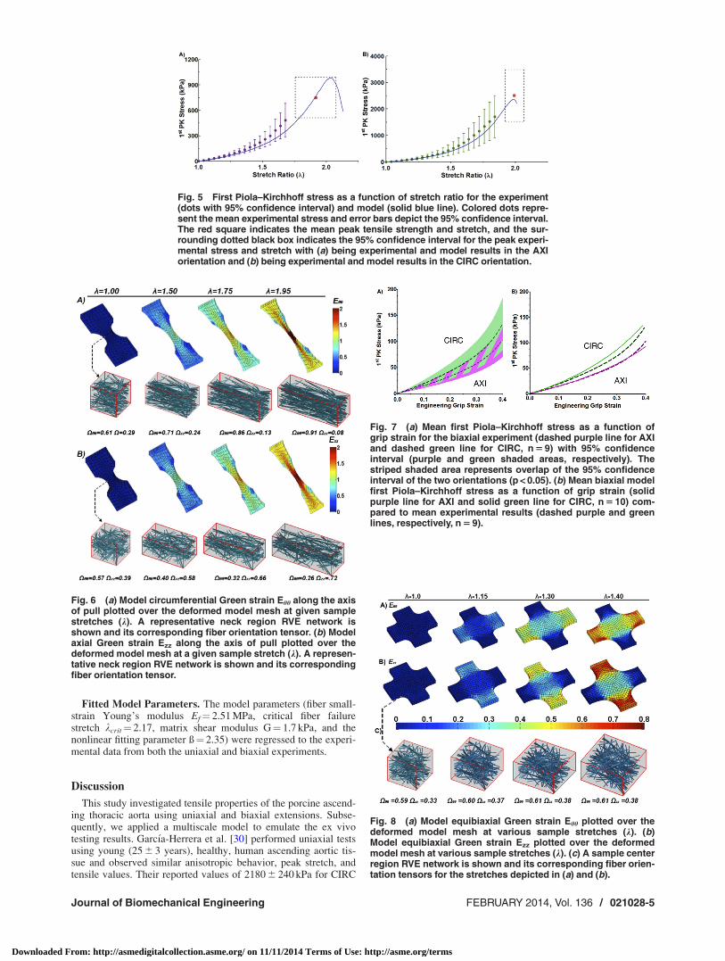
The averaged experimental stress-stretch curves for both theCIRC and AXI orientations are shown in Fig. 5 along with thebest-fit model curves. The specified and regressed model parame-ters of Table 1 allowed the model to match the experimental pre-failure and failure results to within the 95% confidence intervalsfor both orientations.
The neck region of the simulated uniaxial samples (both CIRCand AXI) experienced the largest strains and stresses (not shown),as expected, and also the largest degree of fiber reorientation(Figs. 6(a) and 6(b)). Fibers within the neck region were analyzedfor their mean fiber orientation tensor X. As the simulated uniaxialsample is stretched, fiber alignment changes from its initial orien-tation tensor [Xhh Xzz Xrr] � [0.6 0.3 0.1] and steadily increasesalong the direction of stretch.
Equibiaxial Extension. Biaxial samples (n¼ 9), as with uniax-ial samples, exhibited a nonlinear stress-strain response, charac-teristic of biological tissues (Fig. 3(b)) [27]. As all samplesexhibited similar nonlinear behavior, it is reasonable to considerthe mean response (Fig. 7(a) dotted lines). The tissue showed sim-ilar directional dependence under equibiaxial loading as underuniaxial loading. At peak extension, the stress ratio (CIRC toAXI) was 1.44. The 95% confidence intervals for the two orienta-tions overlapped each other (Fig. 7(a) shaded area).
The biaxial model (Fig. 7(b) solid line) was in good agreementwith the experiments. Stresses in the CIRC direction were slightlyoverpredicted but remained well within the 95% confidence inter-val (Fig. 7(b)).
Similar to the uniaxial simulations, regions with higher strainshad greater changes in fiber rotation and fiber stretch (Fig. 8).However, regions with the largest strain, the arms, are not theregion of interest (Figs. 8(a) and 8(b)). Figure 8(c) depicts an ele-ment from the central region of the biaxial sample, showing thechange in its fiber orientation. Even at 40% strain, in-plane fiberorientation of the elements in this region showed little change.
Fig. 4 (a) Peak tensile strength of ascending aortic samplesfor both uniaxial experiment (solid, n 5 11) and model (diagonallines, n 5 10). (b) Peak stretch of ascending aortic samples forboth uniaxial experiment (solid, n 5 11) and model (diagonallines, n 5 10).
Table 2 Values for parameters used within the model, as well as justification for parameter values. The last four parameters in thetable (shown in bold) were regressed to the combined uniaxial/biaxial data set.
Symbol Description Value Justification
X Network Orientation Xhh¼ 0.6, Xzz¼ 0.3 Extrapolated from structural histology [20]Xrr¼ 0.1
Af Cross-sectional area 31,416 nm2 Elastin fiber radius 100 nm [24,25]U Fiber volume fraction 0.05 Based on Ref. [17]� Poisson’s ratio 0.49 Nearly incompressible [15]wu, lu, tu Uniaxial undeformed dimensions Width¼ 5.00 mm Measured in experiment
Length¼ 13.0 mmThickness: 1.5 mm
wb, lb, tu Biaxial undeformed dimensions Width¼ 6.00 mm Measured in experimentGrip-to-Grip Length¼ 15.0 mmThickness: 1.5 mm
Ef Fiber modulus of elasticity 2.51 MPa Fit to data
kcrit Lambda critical fiber failure 2.17 Fit to data
G Matrix shear modulus 1.7 kPa Fit to data
ß Non-linearity fitting parameter 2.35 Fit to data
Fig. 3 (a) Typical measured uniaxial grip stress versus gripstrain response in the CIRC orientation. (b) Typical measuredequibiaxial grip stresses versus grip strain.
021028-4 / Vol. 136, FEBRUARY 2014 Transactions of the ASME
Downloaded From: http://asmedigitalcollection.asme.org/ on 11/11/2014 Terms of Use: http://asme.org/terms
Fitted Model Parameters. The model parameters (fiber small-strain Young’s modulus Ef¼ 2.51 MPa, critical fiber failurestretch kcrit¼ 2.17, matrix shear modulus G¼ 1.7 kPa, and thenonlinear fitting parameter ß¼ 2.35) were regressed to the experi-mental data from both the uniaxial and biaxial experiments.
Discussion
This study investigated tensile properties of the porcine ascend-ing thoracic aorta using uniaxial and biaxial extensions. Subse-quently, we applied a multiscale model to emulate the ex vivotesting results. Garc�ıa-Herrera et al. [30] performed uniaxial testsusing young (25 6 3 years), healthy, human ascending aortic tis-sue and observed similar anisotropic behavior, peak stretch, andtensile values. Their reported values of 2180 6 240 kPa for CIRC
Fig. 5 First Piola–Kirchhoff stress as a function of stretch ratio for the experiment(dots with 95% confidence interval) and model (solid blue line). Colored dots repre-sent the mean experimental stress and error bars depict the 95% confidence interval.The red square indicates the mean peak tensile strength and stretch, and the sur-rounding dotted black box indicates the 95% confidence interval for the peak experi-mental stress and stretch with (a) being experimental and model results in the AXIorientation and (b) being experimental and model results in the CIRC orientation.
Fig. 6 (a) Model circumferential Green strain Ehh along the axisof pull plotted over the deformed model mesh at given samplestretches (k). A representative neck region RVE network isshown and its corresponding fiber orientation tensor. (b) Modelaxial Green strain Ezz along the axis of pull plotted over thedeformed model mesh at a given sample stretch (k). A represen-tative neck region RVE network is shown and its correspondingfiber orientation tensor.
Fig. 7 (a) Mean first Piola–Kirchhoff stress as a function ofgrip strain for the biaxial experiment (dashed purple line for AXIand dashed green line for CIRC, n 5 9) with 95% confidenceinterval (purple and green shaded areas, respectively). Thestriped shaded area represents overlap of the 95% confidenceinterval of the two orientations (p < 0.05). (b) Mean biaxial modelfirst Piola–Kirchhoff stress as a function of grip strain (solidpurple line for AXI and solid green line for CIRC, n 5 10) com-pared to mean experimental results (dashed purple and greenlines, respectively, n 5 9).
Fig. 8 (a) Model equibiaxial Green strain Ehh plotted over thedeformed model mesh at various sample stretches (k). (b)Model equibiaxial Green strain Ezz plotted over the deformedmodel mesh at various sample stretches (k). (c) A sample centerregion RVE network is shown and its corresponding fiber orien-tation tensors for the stretches depicted in (a) and (b).
Journal of Biomechanical Engineering FEBRUARY 2014, Vol. 136 / 021028-5
Downloaded From: http://asmedigitalcollection.asme.org/ on 11/11/2014 Terms of Use: http://asme.org/terms

and 1140 6 100 kPa for AXI [30] are similar to our reported ten-sile values (2510 6 979 kPa and 750 6 228 kPa for CIRC andAXI, respectively). Vorp et al., however, observed no significantdifference in tensile strength between AXI and CIRC orientedhuman specimens [31], possibly due to older subjects (51 6 6years). Peak stretch at failure showed no significant differencebetween the CIRC and AXI cases and was similar to valuesreported by Garc�ıa-Herrera et al. [30] (2.35 6 10 versus2.00 6 0.1 in CIRC and AXI, respectively) and to our values(1.92 6 0.16 and 1.99 6 0.07 for AXI and CIRC, respectively).
An equibiaxial study by Nicosia et al. [32] on healthy, porcineaortic root wall showed similar directional dependence withstresses at 30% strain, approximately equaling 50 kPa and 90 kPain the AXI and CIRC directions, respectively, comparable to ourresults of 58.4 kPa and 76.2 kPa. Unlike the results presented byNicosia et al., which remained linear up to 40% strain [32], ourresults were pronouncedly nonlinear. The experimental results areconsistent with other studies [30–32]. Having confirmed that ourexperimental data are consistent with previous studies, we willfocus on the model for the remainder of the discussion.
The advantage of a multiscale model is to link observed macro-scale properties to changes in microscale structure (Table 1 andFig. 2). The model was able to capture the anisotropic response inboth the uniaxial and biaxial simulations, in agreement with ourexperimental results. It is important to note that our study, similarto other studies, is however limited in that physiological strainrates are higher than those used; thus, the model should be seen asapproaching the quasi-static limit. The model demonstratedsmaller confidence intervals (for both peak tensile strength andpeak stretch) relative to experimental results, suggesting themethod to model fiber failure could be modified to increase var-iance. Variance could be increased by using a stochastic elementfor fiber failure or introducing more variability in the model net-works. A stochastic failure model would be consistent with thewide range of failure lengths seen for fibers such as collagen,where kcrit can range from 1.2 to 1.7 [33].
In-plane fiber rotation (in the area of interest) was more preva-lent in uniaxial than biaxial simulations (Figs. 6 and 8). Fibers inthe uniaxial CIRC simulations were predominately aligned in thedirection of pull and, therefore, could only stretch and not rotateat the onset of macroscale strain. Fibers in uniaxial AXI simula-tions were predominately aligned perpendicular to the direction ofpull; therefore, when macroscale strain was applied, fibers firstrotated and then extended. The rotation of fibers resulted in lowerforces for the same amount of macroscale strain in uniaxial AXIresults. The model permits for free rotation of fibers, which over-estimates a fiber’s capacity to rotate, as in vivo obstacles such asneighboring fibers and matrix are not taken into account in fiberrotation.
An important simplification of the tissue microstructure in themodel was that a single, idealized network of uniform-diameterfibers was employed in parallel with a neo-Hookean component toaccount for all structural contributions including collagen, elastin,extracellular matrix, cells, and interstitial fluid. Even with thissimplification, the complex mechanical response was still cap-tured by the model. We had expected the neo-Hookean compo-nent to dominate at low strain, representing elastin, while the fibernetwork would dominate at high strains, representing collagen.Therefore, initial model fiber parameters were chosen to simulatecollagen, but those values led to vastly overpredicted forces (datanot shown). When fiber model parameters were fit to the experi-mental data, the resulting values (Table 2) described the behaviorof elastin more closely than collagen, suggesting that elastin playsa dominant role dictating behavior in the tissue. A previous studyalso indicated that intrinsic elastic properties dictate distensibilityof the aorta [34]. In addition, a collagen-based fiber networkwould not be able to achieve a stretch of 2.0 since collagen fibershave a kcrit closer to 1.4 [17], while elastin can reach stretches upto 3 [35]. Histological evidence supports a large elastin contribu-tion as studies have shown more elastin than collagen exists in the
ascending aorta (by dry weight 35% elastin, 22% collagen [19]).Hence, our fitted kcrit value of 2.17 represents the combined effectof the two proteins. Our fitted value (2.51 MPa) of small strainYoung’s modulus is within the range of values reported for elastin(estimated 0.3–10 MPa) in vessel walls [26,36,37].
We have investigated the biomechanical tensile properties ofthe aortic media in the circumferential and axial orientations,which are relevant to rupture of the vessel, but dissection ofATAA also depends on the strength of the tissue in the shear andradial tension [38]. Fitting the model to data from different experi-ments is an important test, and it will be valuable in the future toexamine how the model behaves under different loading configu-rations (e.g., inflation, shear, peeling) that better represent failureas seen in ATAA and to determine whether the model can havepredictive in addition to analytical value. To properly investigatethe radial and shear loading conditions the simplified microstruc-tural organization of this model will need to be revised/expanded.Currently, the model does not consider the concentric, circumfer-ential layers of elastin, collagen, and smooth muscle, which formthe medial lamellae [39]. Unlike the current study, which consid-ers the failure of the fibers within the lamellae, a study with radialand shear loading would involve the failure of the connectionsbetween the lamellae. Therefore, the lamellae’s structure is anessential component in modeling dissection of ATAA, and a twofiber network model, similar to Lai et al. [14], that models colla-gen and the elastic lamellae separately could provide betterinsight.
In spite of the simplifications, the good agreement between themodel and the experiment, for both prefailure and failure behaviorin uniaxial and biaxial tests, indicates a high potential for use inthe more complex geometry, architecture, and loading configura-tion that arise in ATAA.
Acknowledgment
This work was supported by NIH Grant R01-EB005813. MFHwas supported by an NSF Graduate Research Fellowship, CWwas supported by the Louis T. Dosdall Fellowship, and SBS wassupported by the Scott D. and Susan D. Augustine Fellowship.Computations were made possible by a resource grant from theMinnesota Supercomputing Institute. Tissue samples were gener-ously provided by the Visible Heart Lab at UMN.
References[1] Isselbacher, E. M., 2005, “Thoracic and Abdominal Aortic Aneurysms,” Circu-
lation, 111(6), pp. 816–828.[2] Davies, R. R., Goldstein, L. J., Coady, M. A., Tittle, S. L., Rizzo, J. A., Kopf,
G. S., and Elefteriades, J. A., 2002, “Yearly Rupture or Dissection Rates forThoracic Aortic Aneurysms: Simple Prediction Based on Size,” Ann. Thorac.Surg., 73(1), pp. 17–27.
[3] Elefteriades, J. A., 2002, “Natural History of Thoracic Aortic Aneurysms: Indi-cations for Surgery, and Surgical Versus Nonsurgical Risks,” Ann. Thorac.Surg., 74(5), pp. S1877–1880.
[4] Bonnichsen, C. R., Sundt, T. M., III, Anavekar, N. S., Foley, T. A., Morris, M.F., Martinez, M. W., Williamson, E. E., Glockner, J. F., and Araoz, P. A., 2011,“Aneurysms of the Ascending Aorta and Arch: The Role of Imaging in Diagno-sis and Surgical Management,” Expert Rev. Cardiovasc. Ther., 9(1), pp. 45–61.
[5] Guo, D., Hasham, S., Kuang, S.-Q., Vaughan, C. J., Boerwinkle, E., Chen, H.,Abuelo, D., Dietz, H. C., Basson, C. T., Shete, S. S., and Milewicz, D. M.,2001, “Familial Thoracic Aortic Aneurysms and Dissections Genetic Heteroge-neity With a Major Locus Mapping to 5q13-14,” Circulation, 103(20), pp.2461–2468.
[6] Pasta, S., Phillippi, J. A., Gleason, T. G., and Vorp, D. A., 2012, “Effect of An-eurysm on the Mechanical Dissection Properties of the Human Ascending Tho-racic Aorta,” J. Thorac. Cardiovasc. Surg., 143(2), pp. 460–467.
[7] Clouse, W. D., Hallett, J. W., Jr., Schaff, H. V., Spittell, P. C., Rowland, C. M.,Ilstrup, D. M., and Melton, L. J., III, 2004, “Acute Aortic Dissection:Population-Based Incidence Compared With Degenerative Aortic AneurysmRupture,” Mayo Clin. Proc., 79(2), pp. 176–180.
[8] Pape, L. A., Tsai, T. T., Isselbacher, E. M., Oh, J. K., O’Gara, P. T., Evangel-ista, A., Fattori, R., Meinhardt, G., Trimarchi, S., Bossone, E., Suzuki, T.,Cooper, J. V., Froehlich, J. B., Nienaber, C. A., Eagle, K. A., “Aortic Diameter� or¼ 5.5 cm Is Not a Good Predictor of Type A Aortic Dissection: Observa-tions From the International Registry of Acute Aortic Dissection (IRAD),”2007, Circulation, 116(10), pp. 1120–1127.
021028-6 / Vol. 136, FEBRUARY 2014 Transactions of the ASME
Downloaded From: http://asmedigitalcollection.asme.org/ on 11/11/2014 Terms of Use: http://asme.org/terms

[9] Tam, A. S., Catherine Sapp, M., and Roach, M. R., 1998, “The Effect of TearDepth on the Propagation of Aortic Dissections in Isolated Porcine ThoracicAorta,” J. Biomech., 31(7), pp. 673–676.
[10] Sommer, G., Gasser, T. C., Regitnig, P., Auer, M., and Holzapfel, G. A., 2008,“Dissection Properties of the Human Aortic Media: An Experimental Study,”ASME J. Biomech. Eng., 130(2), p. 021007.
[11] Guan, J., Chu, B., Zhang, Y., Zeng, K., and Qiao, A., 2010, “Three-Dimen-sional Computational Simulation of Bypassed Aortic Dissection,” Proceedingsof the 2010 International Conference on Biomedical Engineering and ComputerScience (ICBECS), April 23–25, 2010, pp. 1–4. Available at: http://ieeexplore.ieee.org/xpl/login.jsp?tp=&arnumber=5462494&url=http%3A%2F%2Fieeexplore.ieee.org%2Fxpls%2Fabs_all.jsp%3Farnumber%3D5462494
[12] Gasser, T. C., and Holzapfel, G. A., 2006, “Modeling the Propagation of Arte-rial Dissection,” Eur. J. Mech. – A/Solids, 25(4), pp. 617–633.
[13] Li, B., 2013, “Mathematical Modelling of Aortic Dissection,” Ph.D. thesis, Uni-versity of Glasgow, Glasgow, UK.
[14] Lai, V. K., Lake, S. P., Frey, C. R., Tranquillo, R. T., and Barocas, V. H., 2012,“Mechanical Behavior of Collagen-Fibrin Co-Gels Reflects Transition FromSeries to Parallel Interactions With Increasing Collagen Content,” ASME J.Biomech. Eng., 134(1), p. 011004.
[15] Stylianopoulos, T., and Barocas, V. H., 2007, “Multiscale, Structure-BasedModeling for the Elastic Mechanical Behavior of Arterial Walls,” ASME J.Biomech. Eng., 129(4), pp. 611–618.
[16] Witzenburg, C., Raghupathy, R., Kren, S. M., Taylor, D. A., and Barocas, V.H., 2012, “Mechanical Changes in the Rat Right Ventricle WithDecellularization,” ASME J. Biomech., 45(5), pp. 842–849.
[17] Hadi, M. F., Sander, E. A., and Barocas, V. H., 2012, “Multiscale Model Pre-dicts Tissue-Level Failure From Collagen Fiber-Level Damage,” ASME J. Bio-mech. Eng., 134(9), p. 091005.
[18] Chandran, P. L., and Barocas, V. H., 2007, “Deterministic Material-BasedAveraging Theory Model of Collagen Gel Micromechanics,” ASME J. Bio-mech. Eng., 129(2), pp. 137–147.
[19] Sokolis, D. P., Boudoulas, H., and Karayannacos, P. E., 2008, “Segmental Dif-ferences of Aortic Function and Composition: Clinical Implications,” HellenicJ. Cardiol., 49, pp. 145–154.
[20] Timmins, L. H., Wu, Q., Yeh, A. T., Moore, J. E., and Greenwald, S. E., 2010,“Structural Inhomogeneity and Fiber Orientation in the Inner Arterial Media,”Am. J. Physiol. Heart Circ. Physiol., 298(5), pp. H1537–H1545.
[21] Hiltner, A., Cassidy, J. J., and Baer, E., 1985, “Mechanical Properties of Bio-logical Polymers,” Ann. Rev. Mater. Sci., 15(1), pp. 455–482.
[22] Hoffman, A. S., Grande, L. A., and Park, J. B., 1977, “Sequential Enzymolysisof Human Aorta and Resultant Stress-Strain Behavior,” Biomater. Med. Devi-ces Artif. Organs, 5(2), pp. 121–145.
[23] Haskett, D., Johnson, G., Zhou, A., Utzinger, U., and Vande Geest, J., 2010,“Microstructural and Biomechanical Alterations of the Human Aorta as a Func-tion of Age and Location,” Biomech. Model. Mechanobiol., 9(6), pp. 725–736.
[24] Haslach, H. W., 2010, Maximum Dissipation Non-Equilibrium Thermodynam-ics and its Geometric Structure, Springer, New York.
[25] Winlove, C. P., and Parker, K. H., 1987, “The Influence of the Elastin Lamellaeon Mass Transport in the Arterial Wall,” Adv. Microcirc., 13, pp. 74–81.
[26] Holzapfel, G. A., 2001, “Biomechanics of Soft Tissue,” Handb. Mater. Behav.Models, 3, pp. 1049–1063.
[27] Roach, M. R., and Burton, A. C., 1957, “The Reason for the Shape of theDistensibility Curves of Arteries,” Can. J. Biochem. Physiol., 35(8), pp.681–690.
[28] Han, H. C., and Fung, Y. C., 1991, “Species Dependence of the Zero-StressState of Aorta: Pig Versus Rat,” ASME J. Biomech. Eng., 113(4), pp. 446–451.
[29] Alford, P. W., and Taber, L. A., 2008, “Computational Study of Growth andRemodeling in the Aortic Arch,” Comput. Methods Biomech. Biomed. Eng.,11(5), pp. 525–538.
[30] Garc�ıa-Herrera, C. M., Atienza, J. M., Rojo, F. J., Claes, E., Guinea, G. V., Cel-entano, D. J., Garc�ıa-Montero, C., and Burgos, R. L., 2012, “MechanicalBehaviour and Rupture of Normal and Pathological Human Ascending AorticWall,” Med. Biol. Eng. Comput., 50(6), pp. 559–566.
[31] Vorp, D. A., Schiro, B. J., Ehrlich, M. P., Juvonen, T. S., Ergin, M. A., andGriffith, B. P., 2003, “Effect of Aneurysm on the Tensile Strength and Biome-chanical Behavior of the Ascending Thoracic Aorta,” Ann. Thorac. Surg.,75(4), pp. 1210–1214.
[32] Nicosia, M. A., Kasalko, J. S., Cochran, R. P., Einstein, D. R., and Kunzelman,K. S., 2002, “Biaxial Mechanical Properties of Porcine Ascending Aortic WallTissue,” J. Heart Valve Dis., 11(5), pp. 680–686.
[33] Pins, G. D., Huang, E. K., Christiansen, D. L., and Silver, F. H., 1997, “Effectsof Static Axial Strain on the Tensile Properties and Failure Mechanisms of Self-Assembled Collagen Fibers,” J. Appl. Polym. Sci., 63(11), pp. 1429–1440.
[34] Okamoto, R. J., Xu, H., Kouchoukos, N. T., Moon, M. R., and Sundt, T. M., III,2003, “The Influence of Mechanical Properties on Wall Stress and Distensibil-ity of the Dilated Ascending Aorta,” J. Thorac. Cardiovasc. Surg., 126(3), pp.842–850.
[35] Mukherjee, D. P., Kagan, H. M., Jordan, R. E., and Franzblau, C., 1976, “Effectof Hydrophobic Elastin Ligands on the Stress-Strain Properties of ElastinFibers,” Connect. Tissue Res., 4(3), pp. 177–179.
[36] Koenders, M. M. J. F., Yang, L., Wismans, R. G., van der Werf, K. O., Rein-hardt, D. P., Daamen, W., Bennink, M. L., Dijkstra, P. J., van Kuppevelt, T. H.,and Feijen, J., 2009, “Microscale Mechanical Properties of Single ElasticFibers: The Role of Fibrillin–Microfibrils,” Biomaterials, 30(13), pp.2425–2432.
[37] Wenger, M. P. E., Bozec, L., Horton, M. A., and Mesquida, P., 2007,“Mechanical Properties of Collagen Fibrils,” Biophys. J., 93(4), pp. 1255–1263.
[38] van Baardwijk, C., and Roach, M. R., 1987, “Factors in the Propagation of Aor-tic Dissections in Canine Thoracic Aortas,” J. Biomech., 20(1), pp. 67–73.
[39] Rhodin, J. A. G., 2011, “Architecture of the Vessel Wall,” ComprehensivePhysiology, R. Terjung, ed., Wiley, New York.
Journal of Biomechanical Engineering FEBRUARY 2014, Vol. 136 / 021028-7
Downloaded From: http://asmedigitalcollection.asme.org/ on 11/11/2014 Terms of Use: http://asme.org/terms