preliminary design reviewdavidsommitz
DESCRIPTION
Preliminary Design ReviewDavidSommitzTRANSCRIPT

Zoom Lens Barrel Design
Preliminary Design Review
Dr. Jim Burge OPTI 523
David Sommitz

General The goal of this project is to design a zoom lens mounting system. A pre-existing optical design will be used. However, the lenses will be custom and therefore must be specified. See the following website for the entire lens patent: (http://www.kenrockwell.com/nikon/18-55-ii/patent-7277232.pdf) The zoom lens barrel will need to be mounted to a specific mount type. The method for allowing zoom will need to be clearly specified and discussed.
Key Requirements
• Operational Temperature: 20°+/- 15° • Shock Loading: 20G • Volume of production: 1 • Schedule: Flexible • Lens Spacing: ±100µm • Lens Group Spacing: ±200µm • Lens Decenter: ±50µm • Lens Tilt: ±20arcmin • Intermediate Tolerances: spatial tolerances apply to intermediate zoom positions • Mount Type: C
Lens Prescription
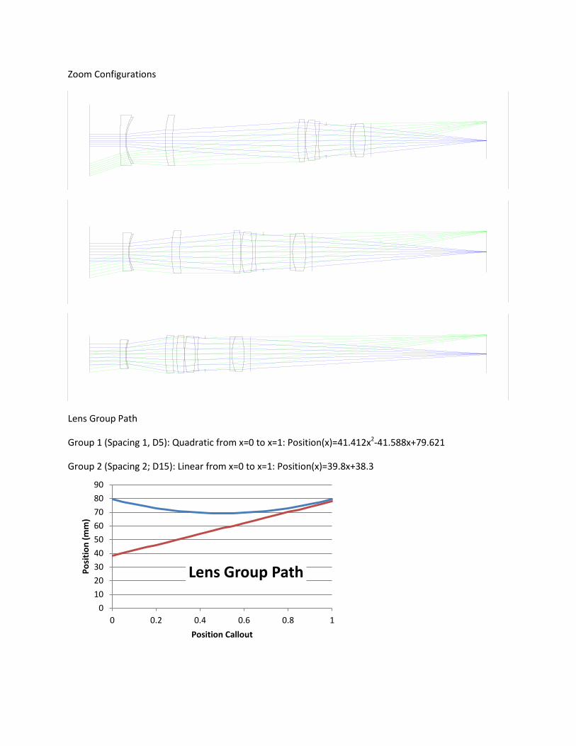
Zoom Configurations
Lens Group Path
Group 1 (Spacing 1, D5): Quadratic from x=0 to x=1: Position(x)=41.412x2-41.588x+79.621
Group 2 (Spacing 2; D15): Linear from x=0 to x=1: Position(x)=39.8x+38.3
0 10 20 30 40 50 60 70 80 90
0 0.2 0.4 0.6 0.8 1
Posi
tion
(mm
)
Position Callout
Lens Group Path

Design Concept
Assembly Cross Section
1. Lens Group 1 Subcell 2. Lens Group 2 Subcell 3. Cam Shaft (lens movement path) 4. Cam Guide (straight lines) 5. Cam Guide Attachment (for accessibility) 6. Focus Compensator 7. Compensator Fastener 8. Cam Shaft Cap (holds parts in place) 9. C-Mount Interface
The general concept of this design will follow a basic cam with the path of the lens groups cut into the shaft:
1 2 3
4 5 7 6 8
9

Two additional cuts will be placed equidistant around the shaft:
The two groups of lenses will be mounted inside two individual barrels, which will move with the cam for zoom paths. Three rods are attached to the barrel, which will follow the cam cuts to extend the zoom.
The inner tube will contain three equi-spaced cuts that are in the shape of the lens paths. The outer tube, which will be the part that is rotated to adjust zoom, will have three linear cuts.

Error Budget
Temperature Expansion-Lens Mounting The lenses will not expand at the same rate as the barrels inside which they are mounted. This will be accommodated with using RTV epoxy, which has an appropriately large CTE as well as a low elastic modulus (see previous design).
Temperature Expansion-Lens Spacing The spacing of the lenses will increase with temperature expansion. This expansion is acceptable because it stays within the requirements:
∆𝐿 = 𝐿 ∗ ∆𝑇 ∗ 𝛼 = 1.5𝑖𝑛 ∗ 15℃ ∗23𝑝𝑝𝑚℃
= 0.5 𝑚𝑖𝑙𝑙𝑖𝑛𝑐ℎ𝑒𝑠 = 13𝜇𝑚
Temperature Expansion-Cam Alignment As long as the components that are involved in zoom movement are made of the same material, temperature should not affect the alignment of the components.
Shock Loading- Lens Mounting These lenses are somewhat larger than the previous lens designs in this class. However, the bond strength of the epoxy used should be enough to prevent 20G shock loading from damaging the lens mounting. As long as the contact area is greater than the required surface area to prevent movement at 20G, the lenses will meet the requirement.
Mass of larges lens: 1.22 grams
Maximum force from shock loading: 0.239N
Tensile Strength of Epoxy: 310 lb/in2=2MPa
Minimum Contact Bond Area: 0.12mm2
Shock Loading-Cam Alignment 20G shock should not damage the cam alignment because everything is constrained, but further analysis is required to confirm this.

Design Issues
Thread Lubricant
In order to prevent galling, seizing, and binding, a lubricant will be used between moving parts in the assembly. This will need to be inserted into the assembly without causing leakage. When the zoom assembly is extended, lubricated parts will be exposed. This could be a problem.
Corner on Cam
When the lens is being moved through zoom, there is a point where it will bottom out and start moving in the other direction. While this should not be an issue, it is hard to tell whether this change in direction will cause problems.
Focus Adjustment
When the focus adjustment is applied, the front part of the barrel should be twisted relative to the back of the camera. When zoom is adjusted, however, the middle part of the barrel is twisted relative to the front of the barrel. This could be a confusing feature for consumers.
Material List
Machined Parts: Aluminum Alloy 6061 (Anodized)
Lubricant: LAMONS Thread Lubricant/Anti-Sieze (GP 450)
http://www.lamons.com/products/thread-lubricant.html
Epoxy (for mounting lenses): Sil-Bond RTV 4500 Aluminum Industrial
http://www.industrialproducts.com/Sil-Bond-RTV-4500-Aluminum-Silicone-Sealant-p/rtv4500aluminum.htm

Potential Problems
The following issues should be preventable with the proper tolerancing.
Focus Compensation Binding –When the focus is adjusted, if the threads are not precisely machined and the materials are not properly centered, the camera will bind. This will be prevented with a position tolerance (concentricity) on the cam guide as well as the compensator part. This tolerance will need to be done before the parts are tapped.
Error in Guidepost Location – The general location of the posts is not terribly important, since the focus can be adjusted. However, the position of the posts relative to each other is very important. If the posts are not properly centered, the lens subcells will not be able to be placed in the cam shaft.

Cam Cut Error – When the guides for the cam shaft are cut, they must be within an acceptable position and orientation of each other. Similarly to the guidepost location, when the zoom is adjusted, any error in the location and orientation will prevent the system from adjusting smoothly.
Size of Guideposts – There are two conflicting limitations on the diameter of the guideposts. If they are too big, they will either not fit in the cam cuts or they will not be able to move. Conversely, if they are too small, there will be a dead zone in the movement of the lens groups.