preliminary geotechnical summary report schuylkill … · preliminary geotechnical summary report ....
TRANSCRIPT
PRELIMINARY GEOTECHNICAL SUMMARY REPORT
SCHUYLKILL RIVER TRAIL EXTENSION PROPOSED RETAINING WALL
SOUTH STREET TO CHRISTIAN STREET PHILADELPHIA COUNTY, PENNSYLVANIA
Prepared for
Schuylkill River Development Corporation Philadelphia, Pennsylvania
and
Urban Engineers, Inc.
Philadelphia, Pennsylvania
Prepared by
American Geotechnical & Environmental Services, Inc. King of Prussia, Pennsylvania
APRIL 2015
A.G.E.S., INC. PROJECT NO. 13004
April 20, 2015 Mr. John E. Federico, P.E., P.P., A.I.C.P. Urban Engineers, Inc. 530 Walnut Street, 14th Floor Philadelphia, Pennsylvania 19106 Re: Preliminary Geotechnical Summary Report Schuylkill River Trail Extension – Proposed Retaining Wall South Street to Christian Street
City of Philadelphia, Philadelphia County, Pennsylvania A.G.E.S. Project No. 13004 Gentlemen: American Geotechnical & Environmental Services (A.G.E.S.), Inc. is pleased to present the Preliminary Geotechnical Summary Report for the above referenced structure site. Included in this report are results of the subsurface investigations, laboratory testing results, along with recommendations concerning the design and construction of the proposed retaining wall. We wish to extend our appreciation to be of service to you. Should you have any questions or require additional information, please contact us. Very truly yours, American Geotechnical & Environmental Services, Inc.
Yojiro Yoshida, P.E. Project Engineer
Solveig Sahlin, P.E. Project Engineer
P:\2013\13004\Geotech Summary Report\Preliminary Geotechnical Summary Report - April 2015.docx
TABLE OF CONTENTS
1.0 INTRODUCTION..............................................................................................................1
1.1 Project Description and Proposed Construction ................................................1
1.2 Purpose and Scope .................................................................................................1
2.0 BACKGROUND INFORMATION .................................................................................3
2.1 Existing Plans .........................................................................................................3
2.2 Previous Subsurface Information .........................................................................3
2.3 Site Reconnaissance ...............................................................................................4
3.0 GEOLOGIC CONDITIONS ............................................................................................6
4.0 PRELIMINARY GEOTECHNICAL INVESTIGATION .............................................8
4.1 Test Boring Results ................................................................................................8
4.2 Laboratory Testing Results .................................................................................10
5.0 ANALYSIS AND CONCLUSIONS ...............................................................................11
6.0 RECOMMENDATIONS .................................................................................................14
6.1 General ..................................................................................................................14
6.2 Soldier Pile and Lagging Wall ............................................................................15
6.3 Cast-in-Place Reinforced Concrete Wall ...........................................................17
6.4 Temporary Shoring .............................................................................................18
6.5 Notes for Drawings ..............................................................................................19
REFERENCES
TABLES
FIGURES
APPENDIX A – ENGINEER’S FIELD BORING LOGS
APPENDIX B – LABORATORY TESTING RESULTS
APPENDIX C – STRUCTURE BORING SHEETS
APPENDIX D – CORE BOX PHOTOS
P:\2013\13004\Geotech Summary Report\Preliminary Geotechnical Summary Report - April 2015.docx
APPENDIX E – CONCEPTUAL STRUCTURE PLAN (Provided by Urban Engineers,
Inc.)
APPENDIX F – GENERALIZED GEOLOGIC PROFILE
APPENDIX G – GEOTECHNICAL ANALYSIS
APPENDIX H – SITE PHOTOS
APPENDIX I – ROADWAY CROSS-SECITON
APPENDIX J – EXISTING BORINGS (Provided by URS Corporation)
APPENDIX K – QA FORM
APPENDIX L – SPECIAL PROVISIONS
APPENDIX M – DESIGN MODEL
P:\2013\13004\Geotech Summary Report\Preliminary Geotechnical Summary Report - April 2015.docx
1.0 INTRODUCTION
1.1 Project Description and Proposed Construction
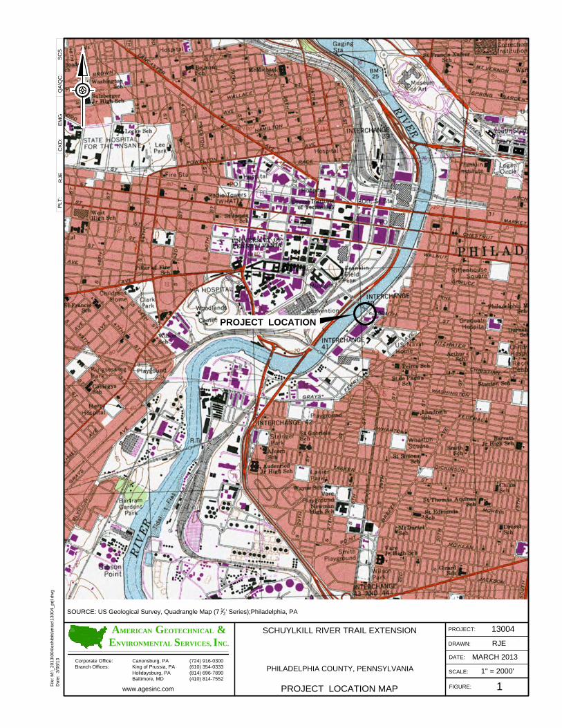
This project involves an approximately 1,400 foot long extension to the Schuylkill River Trail.
The north end of the proposed extension will tie into the proposed Schuylkill Banks Boardwalk
and Plaza area (currently under construction) and the existing stair tower to the South Street
Bridge. The proposed trail will continue south to a proposed terminus near Christian Street. The
Schuylkill River Trail within the area of the wall is located on the east bank of the Schuylkill
River; between the river and the CSX railroad tracks. Refer to Figure 1 for the Project Location
Map.
Proposed construction consists of a 12 foot wide paved trail, which widens to 14’ in the vicinity
of the plaza area. Protective steel fences will be provided between the trail and the CSX railroad
tracks and also between the trail and the Schuylkill River. In order to construct the proposed trail
extension, an approximately 90 foot long retaining wall will be constructed just south of the
Schuylkill Banks Boardwalk and Plaza to span a fairly large washout area. Based on preliminary
drawings, the maximum exposed height of the retaining wall is approximately 8’-0”.
1.2 Purpose and Scope
This submission represents a preliminary geotechnical summary for the proposed retaining wall for the Schuylkill River Development Corporation. The objective of this report is to present the information determined from the preliminary site investigation, office research, subsurface investigation, laboratory testing, and analysis for the above referenced project. Accordingly, our tasks for this submission include:
• Review published geology, and complete a site visit to identify features that may impact
our interpretation of the subsurface conditions;
P:\2013\13004\Geotech Summary Report\Preliminary Geotechnical Summary Report - April 2015.docx 1
• Perform a subsurface exploration program behind the proposed retaining wall at location
determined by Urban Engineers, Inc.
• Conduct laboratory testing on select soil samples and rock cores;
• Interpret the subsurface data and prepared a generalized geologic profile at the proposed
structure location;
• Prepare this report, documenting the data collected and analyses performed and provide
recommendations concerning the type and depth of foundation support for the wall,
relevant design parameters, and site preparation criteria.
P:\2013\13004\Geotech Summary Report\Preliminary Geotechnical Summary Report - April 2015.docx 2
2.0 BACKGROUND INFORMATION
2.1 Existing Plans
The proposed wall will be constructed at the existing washout area to accommodate a proposed
14 foot wide paved trail path. Refer to site photos included in Appendix H for the existing
condition of the proposed wall location.
2.2 Previous Subsurface Information
Subsurface information from three (3) nearby projects was reviewed (Appendix J).
URS Corporation provided Structure Boring Sheets for the Schuylkill River Boardwalk and
Plaza project. The Schuylkill River Boardwalk and Plaza project involves extension to the
Schuylkill River Trail. The proposed retaining wall is a part of the construction of the trail
extension. Applicable borings (Borings A-1 and A-2) were drilled for the Plaza directly north of
the proposed retaining wall. Soil in the borings indicated various granular and fine-grained fill
(SM, CL, sc, sp) over granular residual soil (sm, gm) to the top of bedrock. Top of rock was
encountered at depths varying from 20.4 feet (Boring A-1) to 23.6 feet (Boring A-2). Bedrock
consists of medium hard to very hard, slightly weathered to fresh mica schist, amphibolite, and
schist.
Structure plans from the reconstruction of the South Street Bridge were also reviewed. The
South Street Bridge is located approximately 200 feet north of the proposed retaining wall. Two
(2) borings (Borings S11-19 and S11-20) were drilled for the proposed Pier 11, adjacent to the
existing stairway north of the retaining wall. Soils reported in the boring logs are various
granular and fine-grained soil layers (SM, GP-SP, ML, SP) to the top of bedrock. Top of rock in
the borings were encountered at depths varying from 36.7 feet (S11-19) to 28.1 feet (S11-20).
Bedrock consists of medium hard to hard, slightly weathered to fresh mica schist.
P:\2013\13004\Geotech Summary Report\Preliminary Geotechnical Summary Report - April 2015.docx 3
Structure plans for the proposed access ramp from the South Street Bridge to the Schuylkill
River Trail (north of the South Street Bridge) were reviewed. The proposed access ramp is
located immediately north of the South Street Bridge. Three (3) borings (Borings TB-01, TB-02,
and TB-03) were drilled for the proposed access ramp north of the retaining wall. Soil in the
borings indicated various granular and fine-grained fill and residual soil layers. Bedrock was not
cored in the borings. Top of saprolite/top of highly weathered bedrock in the borings were
encountered at approximate depths 33.0 feet (TB-01), 42.5 feet (TB-02) to 38.5 feet (TB-03).
The saprolite/highly weathered bedrock consists of weathered schist.
2.3 Site Reconnaissance
A preliminary site reconnaissance was performed on February 6, 2013 to view the site and to
verify site features and access routes for the drill equipment. Refer to Site Photographs included
in Attachment H. The proposed retaining wall will be located between the Schuylkill River and
CSX railroad tracks to the south of the South Street Bridge. Surface material in the area
generally consists of random fill material including brick and asphalt fragments. The area
between the South Street Bridge and Boring B-1 is generally flat with little vegetation. In the
general vicinity of proposed Borings B-2 and B-3, there are some smaller trees, brush and vines.
There are existing wood tie bulkheads adjacent to the Schuylkill River on either side of the wash-
out area. The bulkheads appear to be in fair condition and were likely added to protect the
adjacent railroad from being undercut by scour. The existing slope where the proposed retaining
wall will be located varies from approximately 1:1 (H:V) to approximately 4:1 (H:V). There
were no obvious indications of slope instability noted during the site reconnaissance. Erosion
and scour were noted within the wash-out area exposing the tree roots. Visible streambed
material at the base of the wash-out area generally consists of gravel and cobbles with some
sand, silt and clay.
There were no overhead utility lines (electric, cable and phone) observed within the limits of the
proposed retaining wall. A locked, white PVC pipe was noted between the proposed wall and
South Street Bridge. The owner or purpose of this pipe is not known at this time. Additionally,
P:\2013\13004\Geotech Summary Report\Preliminary Geotechnical Summary Report - April 2015.docx 4

there is an underground cable trench between the CSX rails and the proposed retaining wall.
There are also underground drainage pipes, discharging into the Schuylkill River directly north
of the proposed retaining wall location.
P:\2013\13004\Geotech Summary Report\Preliminary Geotechnical Summary Report - April 2015.docx 5
3.0 GEOLOGIC CONDITIONS
The geologic literature indicates that the proposed wall is within the Lowland and Intermediate
Upland Section of the Atlantic Coast Plain Province. The dominant topographic form of the
Lowland and Intermediate Upland Section is characterized by flat upper terrace surfaces cut by
shallow valleys. The underlying material generally consists of unconsolidated to poorly
consolidated sand and gravel underlain by schist, gneiss and other metamorphic rocks.
Based on the published literature the material below the proposed wall location is expected to
consist of the Trenton Gravel (refer to Figure 2 – Geology Map). However, the geologic contact
with the Pensauken and Bridgeton Formations, undifferentiated and Wissahickon formation are
mapped to be in close proximity to the proposed wall location. The Trenton Gravel Formation
consists of unconsolidated sands and gravels and may be hundreds of feet in thickness. The
Trenton Gravel was deposited by fluvial erosion. In general, the Trenton Gravel consists of gray
or pale-reddish-brown very gravelly sand with layers of cross-bedded sand. It also includes clay
and silt layers. The Pensauken and Bridgeton Formations, undifferentiated consist of cross-
stratified, unconsolidated material. Specifically, the material is reported to be dark-reddish-
brown sand with some thin beds of fine gravel and rare layers of clay or silt. The Wissahickon
formation generally consists of mica schist or gneiss bedrock. Depth to bedrock within the
Wissahickon formation is generally shallow however it can be highly variable with zones of
highly weathered rock interbedded with less weathered material.
Although the project is underlain by unconsolidated (soil) material, bedrock was not expected to
be excessively deep because of the close proximity to the geologic contact of the Wissahickon
formation. Bedrock was encountered between depths of 19.5 and 30.0 feet below ground
surface.
From a review of the United States Department of Agriculture (USDA) Web Soil Survey, the
proposed project is noted as being associated with Urban Land (Ub) which indicates that the
surface is covered with pavement, buildings and other artificially covered areas. Therefore,
P:\2013\13004\Geotech Summary Report\Preliminary Geotechnical Summary Report - April 2015.docx 6

specific soil information is not available and is expected that the soils near the proposed wall will
be highly variable.
P:\2013\13004\Geotech Summary Report\Preliminary Geotechnical Summary Report - April 2015.docx 7
4.0 PRELIMINARY GEOTECHNICAL INVESTIGATION
A subsurface exploration program was completed between August 6 and August 8, 2013.
Stations, offsets, and elevations for the borings were provided by Urban Engineers, Inc. Drilling
was completed by TRC Engineers, Inc. with boring inspection performed by A.G.E.S., Inc.
personnel. A total of four (4) borings, three (3) structure borings and one (1) offset boring, were
drilled for the proposed retaining wall structure. Engineer’s Boring Logs are included in
Appendix A. Refer to TS&L Plan included in Appendix E. Plotted Structure Borings Sheets are
included in Appendix C. Photographs of the core boxes are provided in Appendix D. The
Summary of Subsurface Explorations is detailed in Table 1.
Soil sampling was conducted using a Split Spoon Sampler in accordance with ASTM Design
Method D1586-84. The samples were collected continuously by a 2-inch outside diameter Split
Spoon Sampler that was driven 18 inches into the soil with blows from a 140 pound hammer
falling a distance of 30 inches. The number of blows required to drive the sampler for each 6-
inch interval was recorded; with the cumulative number of blows for the last two (2) 6-inch
intervals designated as the “Standard Penetration Resistance” or N-value. This value generally
gives an indication of the in-situ relative density of granular soils or consistency of fine-grained
soils and, in turn, their shear strength and compressibility. The N-values along with a visual
identification of the materials are recorded. The soil sampling was advanced using a hollow-
stem auger until bedrock was encountered.
Once bedrock was encountered, continuous core samples were obtained. Bedrock samples with
a minimum 2-inch diameter were obtained and visually identified with core recoveries and Rock
Quality Designation (RQD) values measured by the boring inspector. The rock core description,
core recovery for each core interval, and the RQD values (expressed in percent) for each
lithologic unit are recorded.
4.1 Test Boring Results
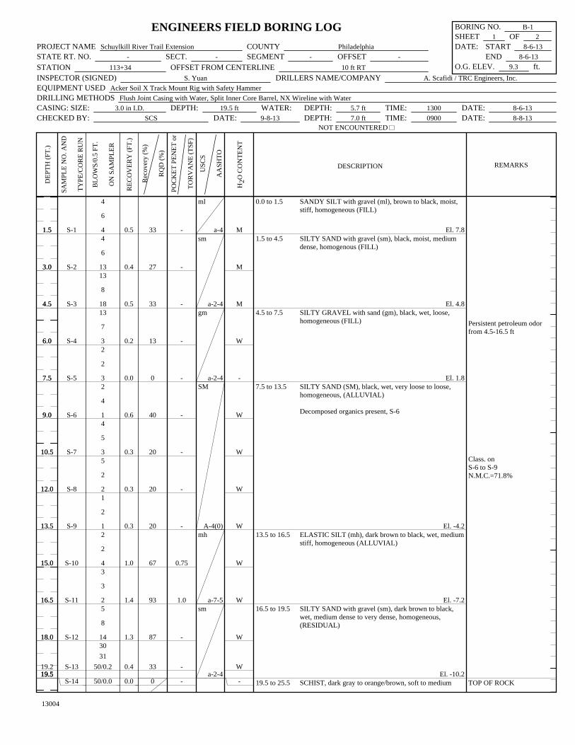
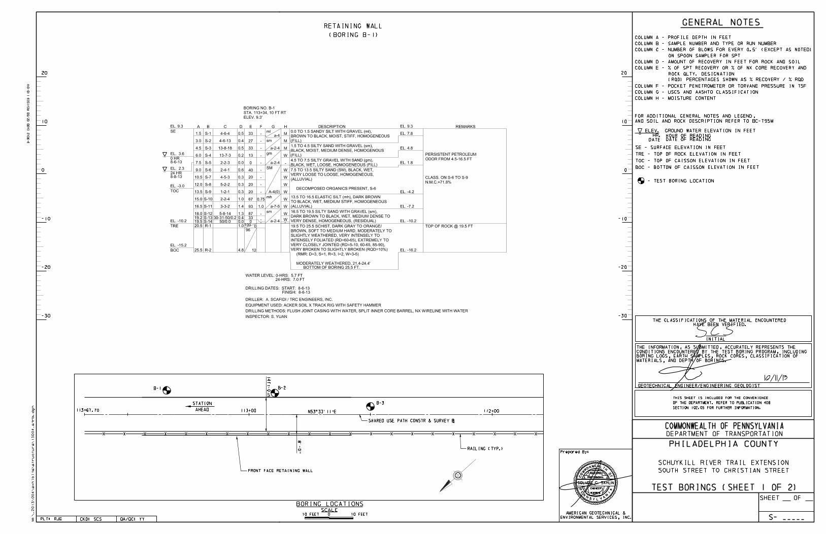
Boring B-1 was drilled near the beginning of the proposed retaining wall and approximately 20 feet behind the front face of the wall. Soils encountered consisted of fill material, alluvial and
P:\2013\13004\Geotech Summary Report\Preliminary Geotechnical Summary Report - April 2015.docx 8
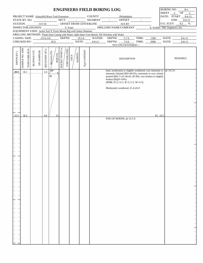
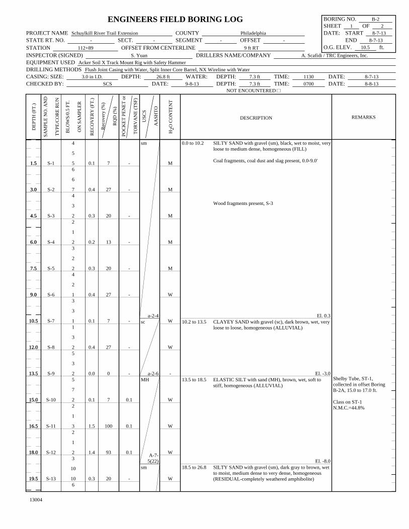
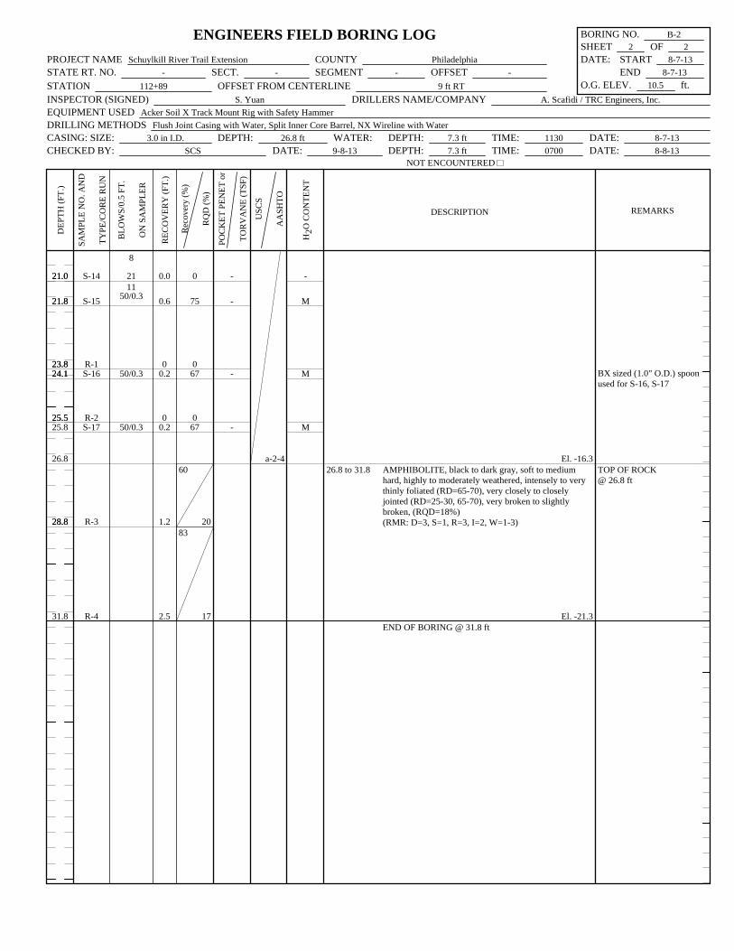
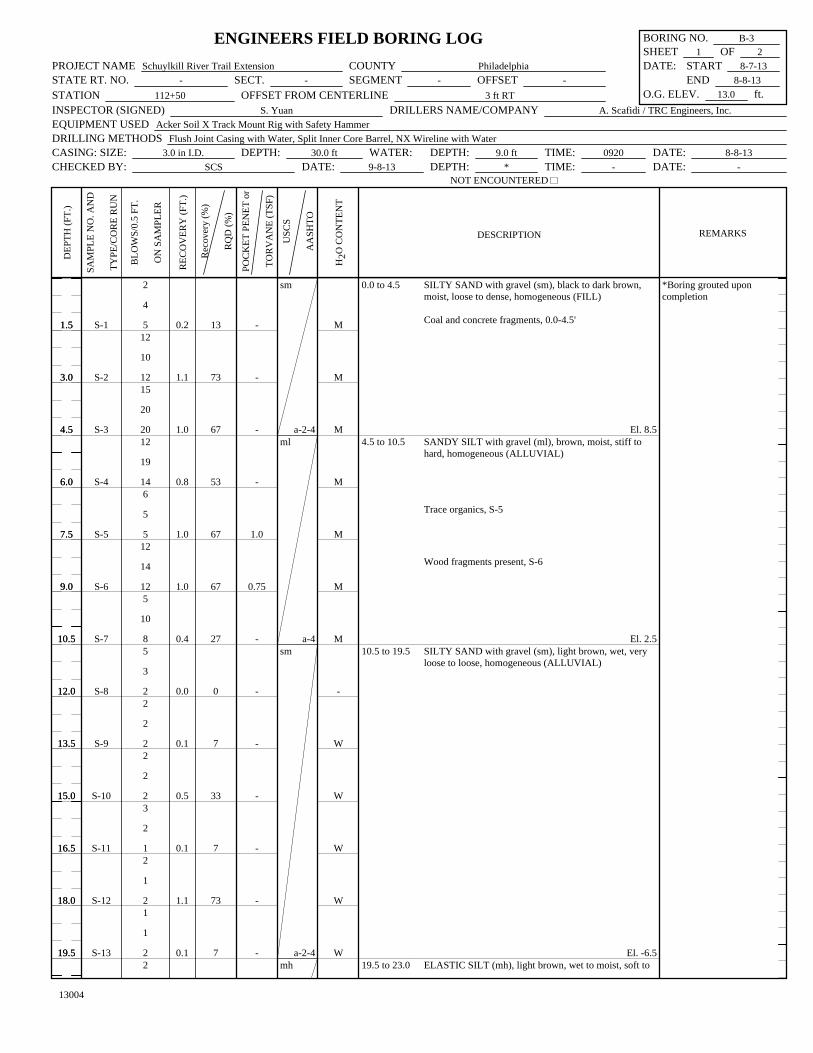
residual soils. Fill material consisted of fine and coarse grained material. Coarse grained fill material consisted of wet to moist, very loose to medium dense, silty sand to silty gravel (sm,gm). Fine grained fill material consisted of moist, stiff sandy silt (ml). Thickness of the fill material was 7.5 feet. Alluvial soil was encountered under the fill material. Alluvial soil consisted of coarse and fine grained material. Coarse grained alluvial soil consisted of wet, very loose to loose silty sand (SM). Fine grained fill material consisted of wet, medium stiff elastic silt (mh). Thickness of the alluvial soil was 9.0 feet. Residual soil encountered below the alluvial soil and above top of rock consisted of wet, medium dense to very dense silty sand with gravel (sm). Thickness of the residual soil was 3.0 feet. Bedrock consisted of schist. Schist was described as soft to medium hard, moderately to slightly weathered with a stratum RQD of 10 percent. The boring was terminated at a depth of 25.5 feet within schist. The 0-hour and 24-hour groundwater level readings were 5.7 and 7.0 feet below the ground surface, respectively. Petroleum odor was noted in soil samples between depths of 4.5 and 16.5 feet. Boring B-2 was drilled near the middle of the proposed retaining wall approximately 19 feet behind the front face of the wall. Soils encountered consisted of fill material, alluvial and residual soils. Fill material consisted of wet to moist, very loose to medium dense silty sand with gravel (sm). Thickness of the fill material was 10.2 feet. Alluvial soil was encountered under the fill material. Alluvial soil consisted of coarse and fine grained material. Coarse grained alluvial soil consisted of wet, very loose to loose clayey sand with gravel (sc). Fine grained fill material consisted of wet, soft to stiff elastic silt (mh). Thickness of the alluvial soil was 8.3 feet. Residual soil encountered below the alluvial soil and above top of rock consisted of wet to moist, medium dense to very dense silty sand with gravel (sm). Thickness of the residual soil was 8.3 feet. Bedrock consisted of amphibolite. Amphibolite was described as soft to medium hard, highly to moderately weathered with a stratum RQD of 18 percent. The boring was terminated at a depth of 31.8 feet. The 0-hour and 24-hour groundwater level readings were 7.3 feet below the ground surface. Boring B-3 was drilled near the end of the proposed retaining wall approximately 13 feet behind the front face of the wall. Soils encountered consisted of fill material, alluvial and residual soils. Fill material consisted of moist, loose to dense silty sand with gravel (sm). Thickness of the fill material was 4.5 feet. Alluvial soil was encountered under the fill material. Alluvial soil consisted of coarse and fine grained material. Coarse grained alluvial soil consisted of wet, very
P:\2013\13004\Geotech Summary Report\Preliminary Geotechnical Summary Report - April 2015.docx 9
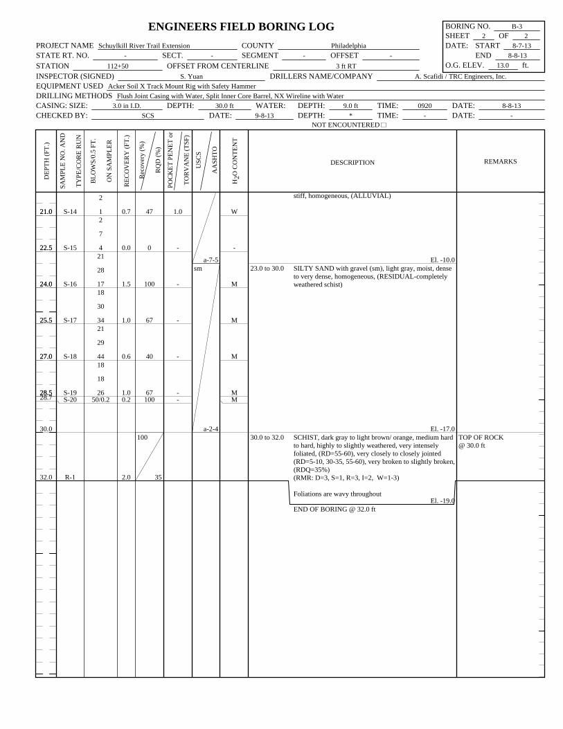
loose to loose silty sand with gravel (sm). Fine grained fill material consisted of moist, soft to hard elastic silt and sandy silt with gravel (mh, ml). Thickness of the alluvial soil was 18.5 feet. Residual soil encountered below the alluvial soil and above top of rock consisted of moist, dense to very dense silty sand with gravel (sm). Thickness of the residual soil was 7.0 feet. Bedrock consisted of schist. Schist was described as medium hard to hard, highly to slightly weathered with a stratum RQD of 35 percent. The boring was terminated at a depth of 32.0 feet. The 0-hour groundwater reading was 9.0 feet below the ground surface. The boring was grouted upon completion and 24-hour reading was not obtained. 4.2 Laboratory Testing Results
Laboratory testing for this project consisted of two (2) soil classification tests, one (1) direct
shear test, and one (1) corrosion test on soil. The Summary of Laboratory Testing is shown in
Table 2 and the Laboratory Test Result sheets are included in Appendix B.
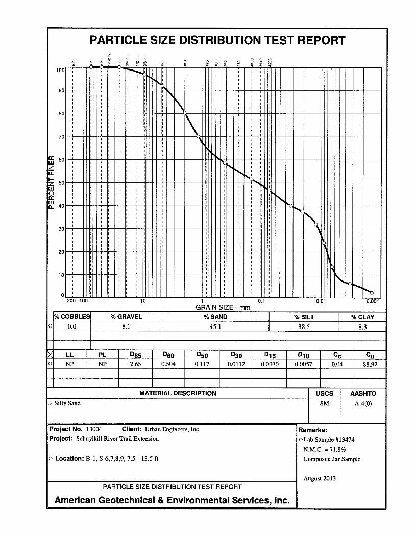
Soil classification testing of the alluvial soil indicated that the soil was non-plastic silty sand
(SM) and elastic silt with sand (MH). Natural moisture content of the soil varied from 44.8 to
71.8 percent.
A direct shear test was performed on the material that was classified as MH. The direct shear
test yielded an ultimate friction angle of 20.9 degrees and an ultimate cohesion of 0.065 tsf.
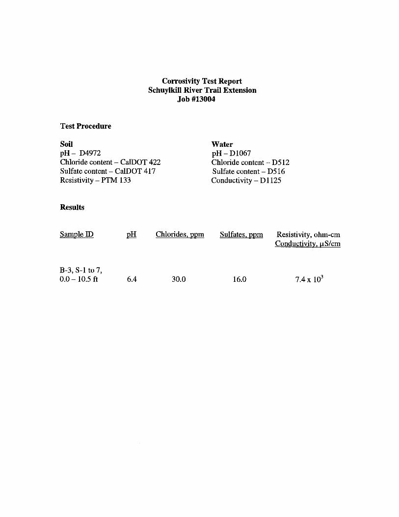
Corrosion test was performed on a composite jar sample from the existing fill material and
alluvial soil. Based on the corrosion test result, the soil had a pH of 6.4, chlorides of 30.0 ppm,
sulfate of 16.0 ppm, and minimum resistivity of 7,400 ohm-cm. Based on these results, in-situ
soil at the project site is not potentially corrosive.
P:\2013\13004\Geotech Summary Report\Preliminary Geotechnical Summary Report - April 2015.docx 10
5.0 ANALYSIS AND CONCLUSIONS
A total of three (3) structure borings were drilled for the proposed retaining wall. In general
borings encountered the existing fill material near the surface underlain by alluvial and residual
soils. The existing fill material generally consisted of very loose to dense coarse grained silty
sand and gravel. Alluvial soil consisted of silty sand and elastic silt. Elastic silt exhibited
relatively low blow counts. Direct shear test was performed on an undisturbed soil sample from
the elastic silt layer. The direct shear test yielded internal friction angle of 20.9 degrees.
Residual soil was generally described as medium dense to very dense silty sand with gravel.
Bedrock was encountered 19.5 to 30.0 feet below the ground surface and consisted of soft to
hard schist and soft to medium amphibolite.
Prior to the subsurface exploration, wall alternatives considered for the proposed retaining wall
included: pre-cast concrete modular wall (T-Wall), stone gabion basket wall, soldier pile and
lagging wall, cast-in-place reinforced concrete gravity wall, and sheet pile wall. Based on the
preliminary cost and construction analyses, a T-Wall alternate appeared to be the preferred wall
alternative. However, the subsurface exploration program revealed the presence of weak elastic
silt layer below the streambed elevation. Based on analyses performed, overexcavation of this
weak material was required for a T-Wall alternate to satisfy bearing capacity, external stability
requirements and to not encroach on the underground fiber optics. Therefore, additional cost
estimates and additional designs were performed incorporating the information from the
subsurface exploration program. Wall alternatives considered for the revised cost estimate
included: pre-cast concrete modular wall (T-Wall) with overexcavation of weak material, soldier
pile and lagging wall, cast-in-place reinforced concrete wall supported on piles and without piles,
stone gabion basket wall, unreinforced concrete gravity wall, and sheet pile wall. The soldier
pile and lagging wall alternate was determined to be the most cost effective alternate.
Based on the analyses, a sheet pile wall is not a feasible alternate due to the shallow depth to
bedrock.
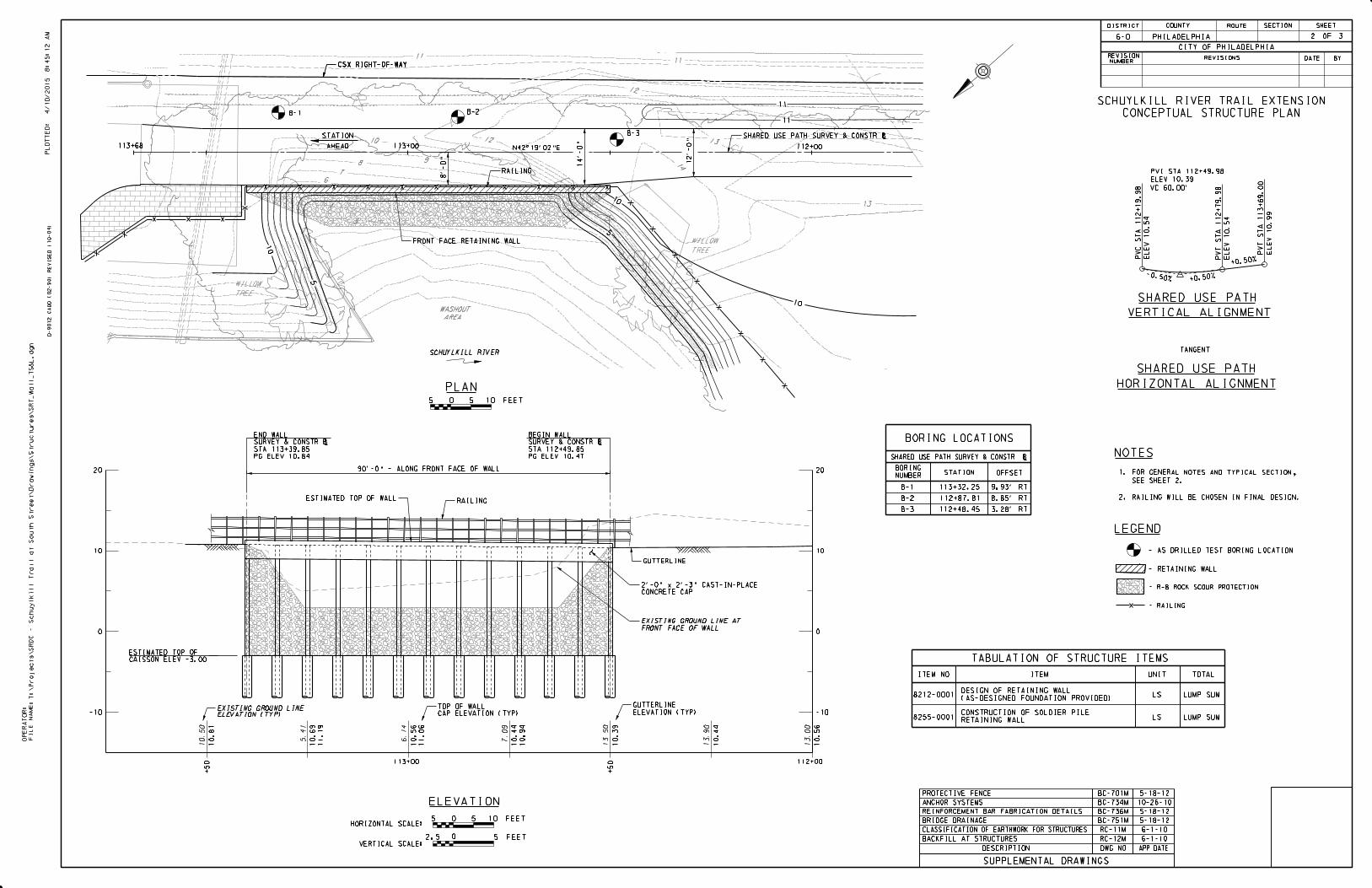
The proposed top of wall elevation ranges from elevation 10.89 feet at the beginning of the wall
to 11.26 feet at the end of the wall. The proposed streambed elevation in front of the wall is
P:\2013\13004\Geotech Summary Report\Preliminary Geotechnical Summary Report - April 2015.docx 11
approximately at elevation 3.0 feet. Bottom of lagging and/or top of caisson is proposed at 6.0
feet below the proposed grade in front of the wall at elevation -3.0 feet. As a result, the design
height of the wall is 14.0 feet. Caissons are to be 2.5 feet in diameter and will be spaced at a
center to center spacing of 8.0 feet. In order to achieve fixity at the tip, caissons are to be
advanced 5.0 feet into bedrock. Lateral deflection at the top of the caisson was calculated to be
0.45 inches which is less than the allowable limit of 0.5 inches. Lateral deflection at the top of
the wall was calculated to be 1.18 inches. Sliding and overturning were also evaluated.
Performance ratios of both sliding and overturning were greater than 1.0. Calculations for the
soldier pile and lagging wall alternate are included in Appendix G.
Other Findings
• The proposed retaining wall is located in an washout area along Schuylkill River and
signs of scour and erosion were observed during field reconnaissance. Scour protection
will be provided per PennDOT DM-4.
• Based on the corrosion test performed on a soil sample from boring, soil at the project
site is not potentially corrosive. However, due to the presence of the Schuylkill River,
which has numerous sources of potentially corrosive material flowing into the river in
front of the proposed retaining wall, the project site is treated as potentially corrosive.
• Since the wall system is supported by bedrock, settlement is not expected to be a concern.
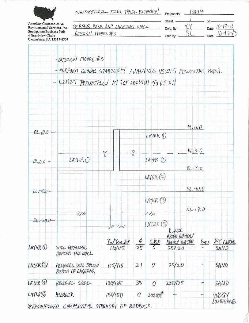
• Global stability of the proposed retaining wall was also evaluated. Shear resistance from
caissons were considered in the analysis. Based on the analysis, global stability is not
expected to be a concern.
• If temporary shoring is required, utilize parameters included in the Recommendation
Section.
P:\2013\13004\Geotech Summary Report\Preliminary Geotechnical Summary Report - April 2015.docx 12

• Petroleum odor was noted for soil samples from Boring B-1 between depth 4.6 and 16.5
feet. Any material excavated shall be handled in accordance with Specification Section
026113 – Excavation of Contaminated Materials Handling.
P:\2013\13004\Geotech Summary Report\Preliminary Geotechnical Summary Report - April 2015.docx 13
6.0 RECOMMENDATIONS
The following is a list of recommendations for this project:
6.1 General
• The construction, including any temporary construction, is to be performed in accordance
with PennDOT Publication 408. The Contractor is responsible for the stability of all
excavated slopes. Perform all excavation in accordance with OSHA requirements.
• Recommended wall type for the proposed retaining wall is a soldier pile and lagging
wall. Allowable alternate wall type is a cast-in-place reinforced concrete wall
supported on piles.
• Design retaining wall so that none of the wall elements will encroach within 5.0 feet of
existing underground fiber optic cable and do not extend into CSX Railroad right-of-way.
• Utilize frost depth of 3.0 feet in design.
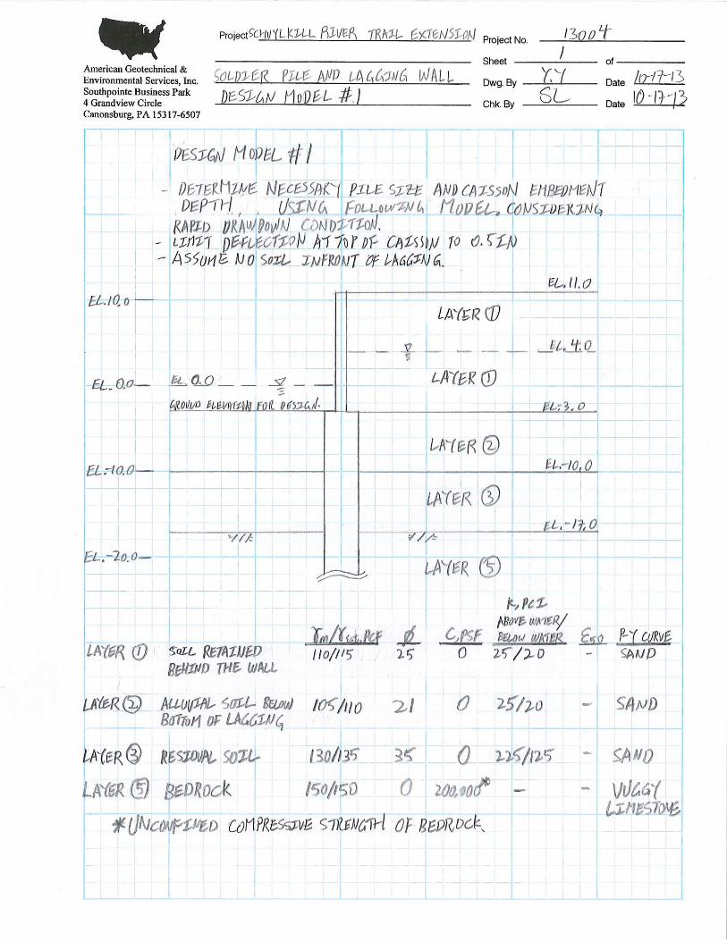
• Consider extreme event condition (i.e., rapid drawdown) in design.
• Backfill behind the retaining wall in accordance with PennDOT Standard RC-12M.
Structure backfill may consist of material meeting AASHTO No. 57 or PennDOT Open
Graded Subbase (OGS) criterion.
• Temporary shoring and/or stream diversion barriers along with dewatering techniques
may be required for construction of substructure units.
• Treat project location as potentially corrosive environment and corrosion protection
measures are required.
• All excavated material shall be handled in accordance with Special Provision ‘Off-Site
Disposal of Contaminated Material’.
P:\2013\13004\Geotech Summary Report\Preliminary Geotechnical Summary Report - April 2015.docx 14
• Provide riprap rock scour protection as per DM-4, Section PP.7.2.5 and as shown on the
plans. Bottom of riprap shall extend to bottom of lagging elevation.
6.2 Soldier Pile and Lagging Wall
• The soldier pile wall must be designed in accordance with all requirements listed in the
AASHTO 2010 LRFD Bridge Design Specifications and PennDOT Design Manual -4,
2012, including all revisions. The design must include complete analyses of the proposed
retaining wall including external stability.
• Temporary casing may be required to maintain an open borehole. If temporary casing is
utilized, maintain concrete levels above the bottom of casing at all times during
extraction to prevent caved material from contaminating the concrete.
• Backfill caisson borehole within 24 hours after drilling to limit the deterioration of the
bearing material.
• The minimum required pile size is W12 x 190.
• The caisson diameter is 2.5 feet.
• Place bottom of lagging at elevation -3.0 feet.
• Extend caissons a minimum of 5.0 feet into bedrock.
• If subsurface condition encountered during construction varies from what was
encountered during subsurface exploration program, perform global stability analysis of
the retaining wall as directed by the Engineer.
• Design soldier pile and lagging wall based on the following parameters:
P:\2013\13004\Geotech Summary Report\Preliminary Geotechnical Summary Report - April 2015.docx 15
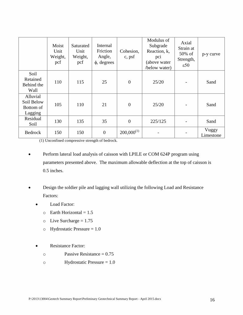
(1) Unconfined compressive strength of bedrock.
• Perform lateral load analysis of caisson with LPILE or COM 624P program using
parameters presented above. The maximum allowable deflection at the top of caisson is
0.5 inches.
• Design the soldier pile and lagging wall utilizing the following Load and Resistance
Factors:
• Load Factor:
o Earth Horizontal = 1.5
o Live Surcharge = 1.75
o Hydrostatic Pressure = 1.0
• Resistance Factor:
o Passive Resistance = 0.75
o Hydrostatic Pressure = 1.0
Moist Unit
Weight, pcf
Saturated Unit
Weight, pcf
Internal Friction Angle,
φ, degrees
Cohesion, c, psf
Modulus of Subgrade
Reaction, k, pci
(above water /below water)
Axial Strain at 50% of
Strength, ε50
p-y curve
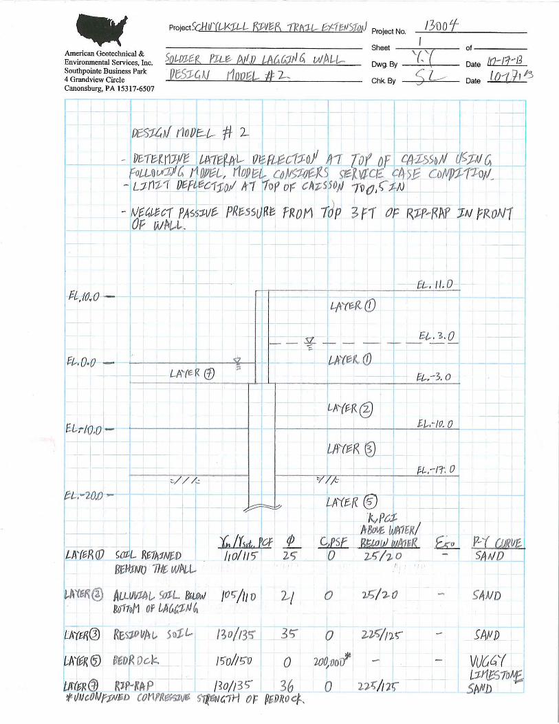
Soil Retained
Behind the Wall
110 115 25 0 25/20 - Sand
Alluvial Soil Below Bottom of Lagging
105 110 21 0 25/20 - Sand
Residual Soil 130 135 35 0 225/125 - Sand
Bedrock 150 150 0 200,000(1) - - Vuggy Limestone
P:\2013\13004\Geotech Summary Report\Preliminary Geotechnical Summary Report - April 2015.docx 16
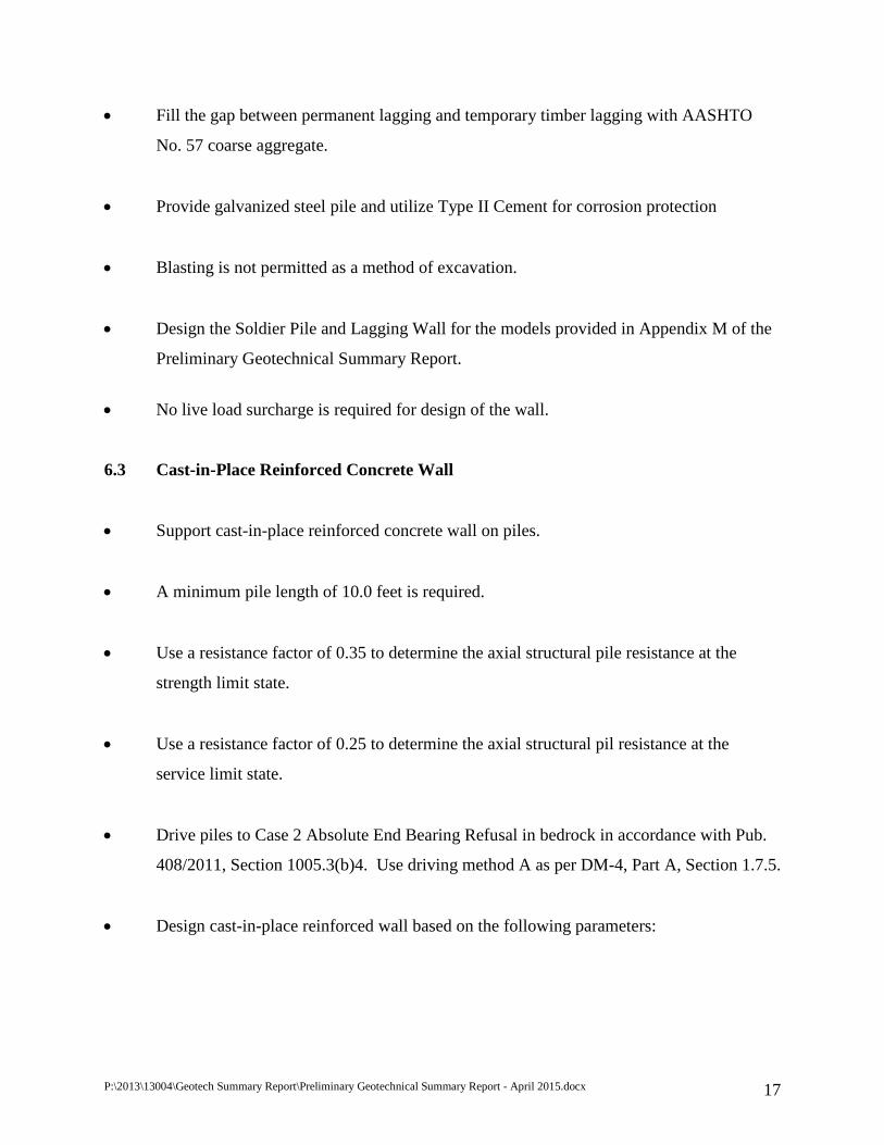
• Fill the gap between permanent lagging and temporary timber lagging with AASHTO
No. 57 coarse aggregate.
• Provide galvanized steel pile and utilize Type II Cement for corrosion protection
• Blasting is not permitted as a method of excavation.
• Design the Soldier Pile and Lagging Wall for the models provided in Appendix M of the
Preliminary Geotechnical Summary Report.
• No live load surcharge is required for design of the wall.
6.3 Cast-in-Place Reinforced Concrete Wall
• Support cast-in-place reinforced concrete wall on piles.
• A minimum pile length of 10.0 feet is required.
• Use a resistance factor of 0.35 to determine the axial structural pile resistance at the
strength limit state.
• Use a resistance factor of 0.25 to determine the axial structural pil resistance at the
service limit state.
• Drive piles to Case 2 Absolute End Bearing Refusal in bedrock in accordance with Pub.
408/2011, Section 1005.3(b)4. Use driving method A as per DM-4, Part A, Section 1.7.5.
• Design cast-in-place reinforced wall based on the following parameters:
P:\2013\13004\Geotech Summary Report\Preliminary Geotechnical Summary Report - April 2015.docx 17
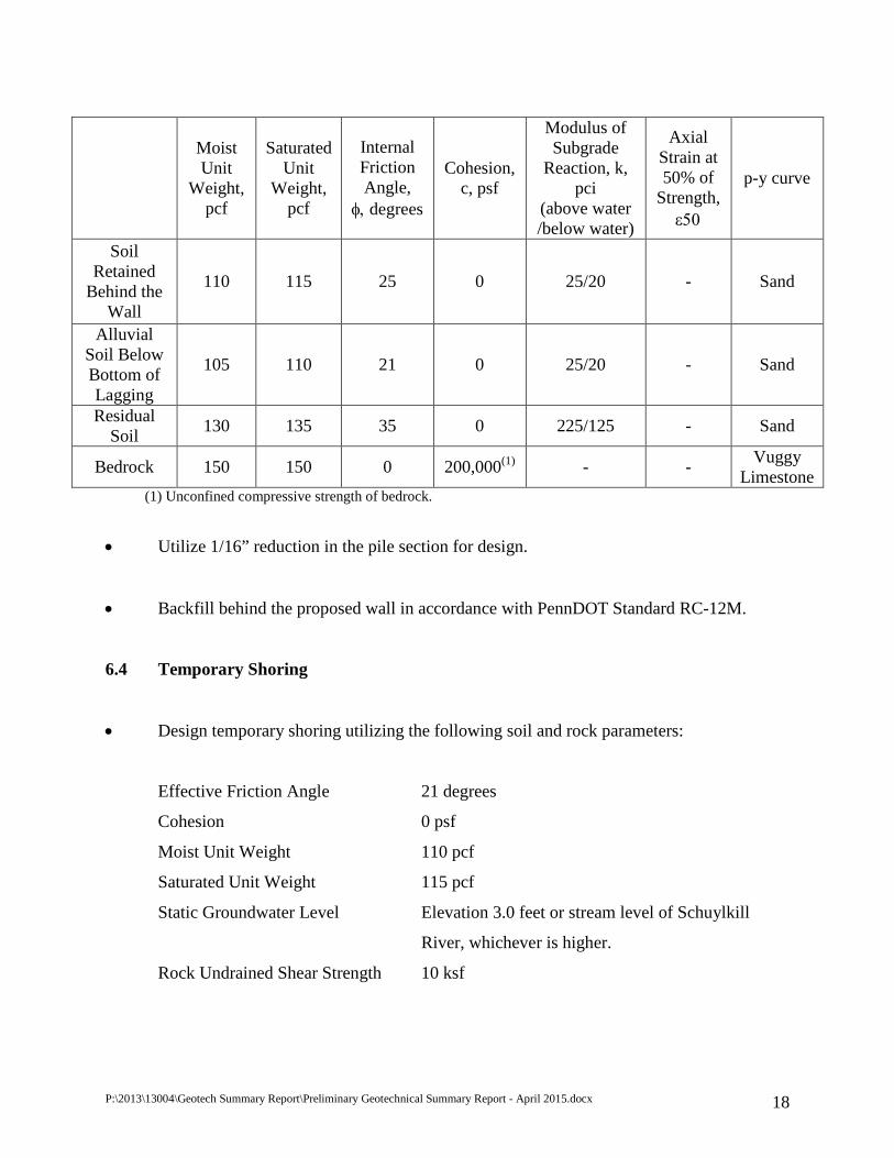
(1) Unconfined compressive strength of bedrock.
• Utilize 1/16” reduction in the pile section for design.
• Backfill behind the proposed wall in accordance with PennDOT Standard RC-12M.
6.4 Temporary Shoring
• Design temporary shoring utilizing the following soil and rock parameters:
Effective Friction Angle 21 degrees
Cohesion 0 psf
Moist Unit Weight 110 pcf
Saturated Unit Weight 115 pcf
Static Groundwater Level Elevation 3.0 feet or stream level of Schuylkill
River, whichever is higher.
Rock Undrained Shear Strength 10 ksf
Moist Unit
Weight, pcf
Saturated Unit
Weight, pcf
Internal Friction Angle,
φ, degrees
Cohesion, c, psf
Modulus of Subgrade
Reaction, k, pci
(above water /below water)
Axial Strain at 50% of
Strength, ε50
p-y curve
Soil Retained
Behind the Wall
110 115 25 0 25/20 - Sand
Alluvial Soil Below Bottom of Lagging
105 110 21 0 25/20 - Sand
Residual Soil 130 135 35 0 225/125 - Sand
Bedrock 150 150 0 200,000(1) - - Vuggy Limestone
P:\2013\13004\Geotech Summary Report\Preliminary Geotechnical Summary Report - April 2015.docx 18

6.5 Notes for Drawings
The following notes are developed for the soldier pile and lagging wall alternate:
• The construction, including any temporary construction, is to be performed in accordance
with PennDOT Publication 408. The Contractor is responsible for the stability of all
excavated slopes. Perform all excavation in accordance with OSHA requirements.
• Temporary shoring and/or stream diversion barriers along with dewatering techniques
may be required for construction of substructure units.
• All excavated material shall be handled in accordance with Specification Section 026113
– Excavation of Contaminated Materials Handling.
• Provide galvanized pile for corrosion protection.
• Temporary casing may be required to maintain an open borehole. If temporary casing is
utilized, maintain concrete levels above the bottom of casing at all times during
extraction to prevent caved material from contaminating the concrete.
• Backfill caisson borehole within 24-hours after drilling to limit the deterioration of the
bearing material.
• Backfill behind the retaining wall in accordance with PennDOT Standard RC-12M.
Structure backfill may consist of material meeting ASSHEO No. 57 or PennDOT Open
Graded Subbase (OGS) criterion.
• Fill the gap between permanent lagging in and temporary timber lagging with AASHTO
No. 57 coarse aggregate.
• Blasting is not permitted as a method of excavation.
P:\2013\13004\Geotech Summary Report\Preliminary Geotechnical Summary Report - April 2015.docx 19
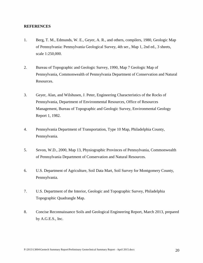
REFERENCES
1. Berg, T. M., Edmunds, W. E., Geyer, A. R., and others, compilers, 1980, Geologic Map
of Pennsylvania: Pennsylvania Geological Survey, 4th ser., Map 1, 2nd ed., 3 sheets,
scale 1:250,000.
2. Bureau of Topographic and Geologic Survey, 1990, Map 7 Geologic Map of
Pennsylvania, Commonwealth of Pennsylvania Department of Conservation and Natural
Resources.
3. Geyer, Alan, and Wilshusen, J. Peter, Engineering Characteristics of the Rocks of
Pennsylvania, Department of Environmental Resources, Office of Resources
Management, Bureau of Topographic and Geologic Survey, Environmental Geology
Report 1, 1982.
4. Pennsylvania Department of Transportation, Type 10 Map, Philadelphia County,
Pennsylvania.
5. Sevon, W.D., 2000, Map 13, Physiographic Provinces of Pennsylvania, Commonwealth
of Pennsylvania Department of Conservation and Natural Resources.
6. U.S. Department of Agriculture, Soil Data Mart, Soil Survey for Montgomery County,
Pennsylvania.
7. U.S. Department of the Interior, Geologic and Topographic Survey, Philadelphia
Topographic Quadrangle Map.
8. Concise Reconnaissance Soils and Geological Engineering Report, March 2013, prepared
by A.G.E.S., Inc.
P:\2013\13004\Geotech Summary Report\Preliminary Geotechnical Summary Report - April 2015.docx 20

TABLES

TABLE 1 SUMMARY OF SUBSURFACE EXPLORATION
SCHUYLKILL RIVER TRAIL EXTENSION - SOUTH STREET TO CHRISTIAN STREET CITY OF PHILADELPHIA, PHILADELPHIA COUNTY, PENNSYLVANIA
P:\2013\13004\Geotech Summary Report\Table 1 - Summary of Subsurface Exploration
By: YZ 09-04-13Chk: SCS 09-04-13
B-1 113+34 10 RT 9.3 - - - 7.5 9.0 3.0 19.5 -10.2 -16.2 5.7 7.0B-2 112+89 9 RT 10.5 - - - 10.2 8.3 8.3 26.8 -16.3 -21.3 7.3 7.3
B-2A (1) 112+89 7 RT 10.5 15.0 - - - 2.0 - 17.0 - -6.5 Dry *B-3 112+50 3 RT 13.0 - - - 4.5 18.5 7.0 30.0 -17.0 -19.0 9.0 *
Total 15.0 0.0 0.0 22.2 37.8 18.3 93.3
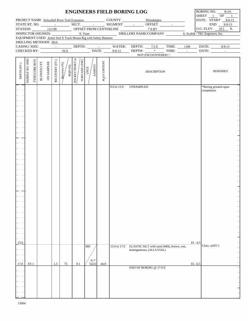
Notes: * - Boring grouted upon completion of drilling.1. Unsampled drilling, 0.0 to 15.0 feet (elevation 10.5 to -4.5 feet). Shelby tube, ST-1, obtained from 15.0 to 17.0 feet (elevation -4.5 to -6.5 feet).
Residual
(ft)
0 HourWater
Elevation(ft)
24 HourWater
Elevation(ft)
Bottomof BoringElevation
(ft)
GroundSurface
Elevation(ft)
Boring Designation
Bituminous Concrete
(ft)
Top of Gravel/Boulder/CobbleLayer
(ft)
Subbase
(ft)
Total
(ft)
Alluvial
(ft)
Unsampled
(ft)
StationOffset from
Centerline
Fill
(ft)
SOIL
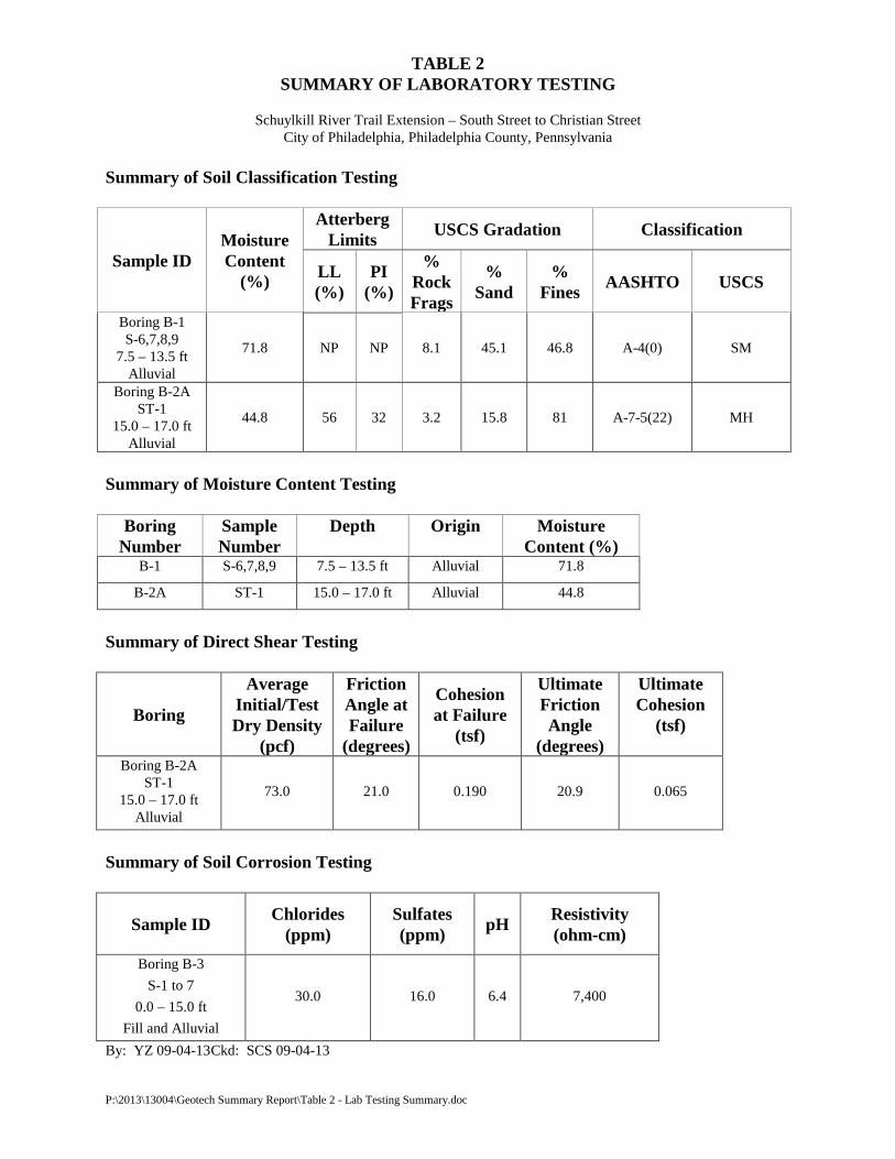
TABLE 2 SUMMARY OF LABORATORY TESTING
Schuylkill River Trail Extension – South Street to Christian Street
City of Philadelphia, Philadelphia County, Pennsylvania Summary of Soil Classification Testing
Sample ID Moisture Content
(%)
Atterberg Limits USCS Gradation Classification
LL (%)
PI (%)
% Rock Frags
% Sand
% Fines AASHTO USCS
Boring B-1 S-6,7,8,9
7.5 – 13.5 ft Alluvial
71.8 NP NP 8.1 45.1 46.8 A-4(0) SM
Boring B-2A ST-1
15.0 – 17.0 ft Alluvial
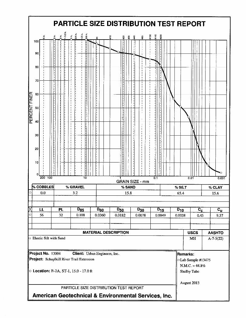
44.8 56 32 3.2 15.8 81 A-7-5(22) MH
Summary of Moisture Content Testing
Boring Number
Sample Number
Depth
Origin Moisture Content (%)
B-1 S-6,7,8,9 7.5 – 13.5 ft Alluvial 71.8
B-2A ST-1 15.0 – 17.0 ft Alluvial 44.8
Summary of Direct Shear Testing
Boring
Average Initial/Test Dry Density
(pcf)
Friction Angle at Failure
(degrees)
Cohesion at Failure
(tsf)
Ultimate Friction Angle
(degrees)
Ultimate Cohesion
(tsf)
Boring B-2A ST-1
15.0 – 17.0 ft Alluvial
73.0 21.0 0.190 20.9 0.065
Summary of Soil Corrosion Testing
By: YZ 09-04-13 Ckd: SCS 09-04-13
Sample ID Chlorides (ppm)
Sulfates (ppm) pH Resistivity
(ohm-cm) Boring B-3
S-1 to 7 0.0 – 15.0 ft
Fill and Alluvial
30.0 16.0 6.4 7,400
P:\2013\13004\Geotech Summary Report\Table 2 - Lab Testing Summary.doc

FIGURES
File: M
:\_2013\004\exhibits\m
isc\13004_prjl.dw
g
Date: 3/08/13
SOURCE: US Geological Survey, Quadrangle Map (7
1
2
' Series);Philadelphia, PA
PLT
:C
KD
:Q
A\Q
C:
PROJECT:
DRAWN:
SCALE:
DATE:
FIGURE:
SCHUYLKILL RIVER TRAIL EXTENSION
PHILADELPHIA COUNTY, PENNSYLVANIA
PROJECT LOCATION MAP
13004
RJE
MARCH 2013
1" = 2000'
1
RJE
EM
GS
CS
PROJECT LOCATION
AMERICAN GEOTECHNICAL &ENVIRONMENTAL SERVICES, INC.
Corporate Office: Canonsburg, PA (724) 916-0300
Branch Offices: King of Prussia, PA (610) 354-0333
Holidaysburg, PA (814) 696-7890
Baltimore, MD (410) 814-7552
www.agesinc.com

File: M
:\_2013\004\exhibits\m
isc\13004_geol.dw
g
Date: 3/08/13
SOURCE: PA Bureau of Topographic & Geologic Survey, DCNR; Bedrock Geology of Pennsylvania
PLT
:C
KD
:Q
A\Q
C:
PROJECT:
DRAWN:
SCALE:
DATE:
FIGURE:
SCHUYLKILL RIVER TRAIL EXTENSION
PHILADELPHIA COUNTY, PENNSYLVANIA
GENERAL GEOLOGY MAP
13004
RJE
MARCH 2013
1" = 2000'
2
RJE
EM
GS
CS
PROJECT LOCATION
AMERICAN GEOTECHNICAL &ENVIRONMENTAL SERVICES, INC.
Corporate Office: Canonsburg, PA (724) 916-0300
Branch Offices: King of Prussia, PA (610) 354-0333
Holidaysburg, PA (814) 696-7890
Baltimore, MD (410) 814-7552
www.agesinc.com
APPENDIX A
ENGINEER’S FIELD BORING LOGS

Schuylkill River Trail Extension – Proposed Retaining Wall Project No. 13004 South Street to Christian Street October 2014 City of Philadelphia, Philadelphia County, Pennsylvania
ENGINEER’S CERTIFICATION I, the undersigned, hereby certify that I have observed the soil samples and rock cores for this project and that the classification of materials and depths presented on the following Engineer’s Field Boring Logs are, to the best of my knowledge, correct as submitted. American Geotechnical & Environmental Services, Inc.
Solveig Salin, P.E. Project Engineer
1.51.5
3.03.0
4.54.5
6.06.0
7.57.5
9.09.0
10.510.5
12.012.0
13.513.5
15.015.0
16.516.5
18.018.0
19.219.519.519.5
S-1
S-2
S-3
S-4
S-5
S-6
S-7
S-8
S-9
S-10
S-11
S-12
S-13
S-14
4
6
44
6
1313
8
1813
7
32
2
32
4
14
5
35
2
21
2
12
2
43
3
25
8
143031
50/0.2
50/0.0
0.5
0.4
0.5
0.2
0.0
0.6
0.3
0.3
0.3
1.0
1.4
1.3
0.4
0.0
33
27
33
13
0
40
20
20
20
67
93
87
33
0
-
-
-
-
-
-
-
-
-
0.75
1.0
-
-
-
ml
a-4sm
a-2-4gm
a-2-4SM
A-4(0)mh
a-7-5sm
a-2-4
M
M
M
W
-
W
W
W
W
W
W
W
W
-
0.0 to 1.5
1.5 to 4.5
4.5 to 7.5
7.5 to 13.5
13.5 to 16.5
16.5 to 19.5
19.5 to 25.5
SANDY SILT with gravel (ml), brown to black, moist,stiff, homogeneous (FILL)
El. 7.8SILTY SAND with gravel (sm), black, moist, mediumdense, homogenous (FILL)
El. 4.8SILTY GRAVEL with sand (gm), black, wet, loose,homogeneous (FILL)
El. 1.8SILTY SAND (SM), black, wet, very loose to loose,homogeneous, (ALLUVIAL)
Decomposed organics present, S-6
El. -4.2ELASTIC SILT (mh), dark brown to black, wet, mediumstiff, homogeneous (ALLUVIAL)
El. -7.2SILTY SAND with gravel (sm), dark brown to black,wet, medium dense to very dense, homogeneous,(RESIDUAL)
El. -10.2SCHIST, dark gray to orange/brown, soft to medium
Persistent petroleum odorfrom 4.5-16.5 ft
Class. onS-6 to S-9N.M.C.=71.8%
TOP OF ROCK
ENGINEERS FIELD BORING LOG BORING NO. B-1SHEET 1 OF
PROJECT NAME Schuylkill River Trail Extension COUNTY Philadelphia DATE: START 8-6-13STATE RT. NO. - SECT. - SEGMENT - OFFSET - END 8-6-13STATION 113+34 OFFSET FROM CENTERLINE 10 ft RT O.G. ELEV. 9.3 ft.INSPECTOR (SIGNED) S. Yuan DRILLERS NAME/COMPANY A. Scafidi / TRC Engineers, Inc.EQUIPMENT USED Acker Soil X Track Mount Rig with Safety HammerDRILLING METHODS Flush Joint Casing with Water, Split Inner Core Barrel, NX Wireline with WaterCASING: SIZE: 3.0 in I.D. DEPTH: 19.5 ft WATER: DEPTH: 5.7 ft TIME: 1300 DATE: 8-6-13CHECKED BY: SCS DATE: 9-8-13 DEPTH: 7.0 ft TIME: 0900 DATE: 8-8-13
NOT ENCOUNTERED
13004
DEP
TH (F
T.)
SAM
PLE
NO
. AN
D
TYPE
/CO
RE
RU
N
BLO
WS/
0.5
FT.
ON
SA
MPL
ER
REC
OV
ERY
(FT.
)
Rec
over
y (%
)
RQ
D (%
)
POC
KET
PEN
ET o
r
TOR
VA
NE
(TSF
)
USC
S
AA
SHTO
H2O
CO
NTE
NT
DESCRIPTION REMARKS
2
20.520.5
25.5
R-1
R-2
1.0
4.8
1000
96
12
hard, moderately to slightly weathered, very intensely tointensely foliated (RD=60-65), extremely to very closelyjointed (RD=5-10, 60-65, 85-90), very broken to slightlybroken (RQD=10%)(RMR: D=3, S=1, R=3, I=2, W=3-5)
Moderately weathered, 21.4-24.4'
El. -16.2END OF BORING @ 25.5 ft
@ 19.5 ft
ENGINEERS FIELD BORING LOG BORING NO. B-1SHEET 2 OF
PROJECT NAME Schuylkill River Trail Extension COUNTY Philadelphia DATE: START 8-6-13STATE RT. NO. - SECT. - SEGMENT - OFFSET - END 8-6-13STATION 113+34 OFFSET FROM CENTERLINE 10 ft RT O.G. ELEV. 9.3 ft.INSPECTOR (SIGNED) S. Yuan DRILLERS NAME/COMPANY A. Scafidi / TRC Engineers, Inc.EQUIPMENT USED Acker Soil X Track Mount Rig with Safety HammerDRILLING METHODS Flush Joint Casing with Water, Split Inner Core Barrel, NX Wireline with WaterCASING: SIZE: 3.0 in I.D. DEPTH: 19.5 ft WATER: DEPTH: 5.7 ft TIME: 1300 DATE: 8-6-13CHECKED BY: SCS DATE: 9-8-13 DEPTH: 7.0 ft TIME: 0900 DATE: 8-8-13
NOT ENCOUNTERED
DEP
TH (F
T.)
SAM
PLE
NO
. AN
D
TYPE
/CO
RE
RU
N
BLO
WS/
0.5
FT.
ON
SA
MPL
ER
REC
OV
ERY
(FT.
)
Rec
over
y (%
)
RQ
D (%
)
POC
KET
PEN
ET o
r
TOR
VA
NE
(TSF
)
USC
S
AA
SHTO
H2O
CO
NTE
NT
DESCRIPTION REMARKS
2
1.51.5
3.03.0
4.54.5
6.06.0
7.57.5
9.09.0
10.510.5
12.012.0
13.513.5
15.015.0
16.516.5
18.018.0
19.519.5
S-1
S-2
S-3
S-4
S-5
S-6
S-7
S-8
S-9
S-10
S-11
S-12
S-13
4
5
56
6
74
3
22
1
23
2
24
2
13
3
11
3
25
3
25
7
22
1
32
1
23
10
106
0.1
0.4
0.3
0.2
0.3
0.4
0.1
0.4
0.0
0.1
1.5
1.4
0.3
7
27
20
13
20
27
7
27
0
7
100
93
20
-
-
-
-
-
-
-
-
-
0.1
0.1
0.1
-
sm
a-2-4sc
a-2-6MH
A-7-5(22)
sm
M
M
M
M
M
W
W
W
-
W
W
W
W
0.0 to 10.2
10.2 to 13.5
13.5 to 18.5
18.5 to 26.8
SILTY SAND with gravel (sm), black, wet to moist, veryloose to medium dense, homogeneous (FILL)
Coal fragments, coal dust and slag present, 0.0-9.0'
Wood fragments present, S-3
El. 0.3CLAYEY SAND with gravel (sc), dark brown, wet, veryloose to loose, homogeneous (ALLUVIAL)
El. -3.0ELASTIC SILT with sand (MH), brown, wet, soft tostiff, homogeneous (ALLUVIAL)
El. -8.0SILTY SAND with gravel (sm), dark gray to brown, wetto moist, medium dense to very dense, homogeneous(RESIDUAL-completely weathered amphibolite)
Shelby Tube, ST-1,collected in offset BoringB-2A, 15.0 to 17.0 ft.
Class on ST-1N.M.C.=44.8%
ENGINEERS FIELD BORING LOG BORING NO. B-2SHEET 1 OF
PROJECT NAME Schuylkill River Trail Extension COUNTY Philadelphia DATE: START 8-7-13STATE RT. NO. - SECT. - SEGMENT - OFFSET - END 8-7-13STATION 112+89 OFFSET FROM CENTERLINE 9 ft RT O.G. ELEV. 10.5 ft.INSPECTOR (SIGNED) S. Yuan DRILLERS NAME/COMPANY A. Scafidi / TRC Engineers, Inc.EQUIPMENT USED Acker Soil X Track Mount Rig with Safety HammerDRILLING METHODS Flush Joint Casing with Water, Split Inner Core Barrel, NX Wireline with WaterCASING: SIZE: 3.0 in I.D. DEPTH: 26.8 ft WATER: DEPTH: 7.3 ft TIME: 1130 DATE: 8-7-13CHECKED BY: SCS DATE: 9-8-13 DEPTH: 7.3 ft TIME: 0700 DATE: 8-8-13
NOT ENCOUNTERED
13004
DEP
TH (F
T.)
SAM
PLE
NO
. AN
D
TYPE
/CO
RE
RU
N
BLO
WS/
0.5
FT.
ON
SA
MPL
ER
REC
OV
ERY
(FT.
)
Rec
over
y (%
)
RQ
D (%
)
POC
KET
PEN
ET o
r
TOR
VA
NE
(TSF
)
USC
S
AA
SHTO
H2O
CO
NTE
NT
DESCRIPTION REMARKS
2
21.021.0
21.821.8
23.823.824.124.1
25.525.525.8
26.8
28.828.8
31.8
S-14
S-15
R-1S-16
R-2S-17
R-3
R-4
8
2111
50/0.3
50/0.3
50/0.3
0.0
0.6
00.2
00.2
1.2
2.5
0
75
067
067
60
2083
17
-
-
-
-
a-2-4
-
M
M
M
26.8 to 31.8El. -16.3
AMPHIBOLITE, black to dark gray, soft to mediumhard, highly to moderately weathered, intensely to verythinly foliated (RD=65-70), very closely to closelyjointed (RD=25-30, 65-70), very broken to slightlybroken, (RQD=18%)(RMR: D=3, S=1, R=3, I=2, W=1-3)
El. -21.3END OF BORING @ 31.8 ft
BX sized (1.0" O.D.) spoonused for S-16, S-17
TOP OF ROCK@ 26.8 ft
ENGINEERS FIELD BORING LOG BORING NO. B-2SHEET 2 OF
PROJECT NAME Schuylkill River Trail Extension COUNTY Philadelphia DATE: START 8-7-13STATE RT. NO. - SECT. - SEGMENT - OFFSET - END 8-7-13STATION 112+89 OFFSET FROM CENTERLINE 9 ft RT O.G. ELEV. 10.5 ft.INSPECTOR (SIGNED) S. Yuan DRILLERS NAME/COMPANY A. Scafidi / TRC Engineers, Inc.EQUIPMENT USED Acker Soil X Track Mount Rig with Safety HammerDRILLING METHODS Flush Joint Casing with Water, Split Inner Core Barrel, NX Wireline with WaterCASING: SIZE: 3.0 in I.D. DEPTH: 26.8 ft WATER: DEPTH: 7.3 ft TIME: 1130 DATE: 8-7-13CHECKED BY: SCS DATE: 9-8-13 DEPTH: 7.3 ft TIME: 0700 DATE: 8-8-13
NOT ENCOUNTERED
DEP
TH (F
T.)
SAM
PLE
NO
. AN
D
TYPE
/CO
RE
RU
N
BLO
WS/
0.5
FT.
ON
SA
MPL
ER
REC
OV
ERY
(FT.
)
Rec
over
y (%
)
RQ
D (%
)
POC
KET
PEN
ET o
r
TOR
VA
NE
(TSF
)
USC
S
AA
SHTO
H2O
CO
NTE
NT
DESCRIPTION REMARKS
2
15.0
17.0 ST-1 1.5 75 0.1
MH
A-7-5(22) 44.8
0.0 to 15.0
15.0 to 17.0
UNSAMPLED
El. -4.5ELASTIC SILT with sand (MH), brown, wet,homogeneous, (ALLUVIAL)
El. -6.5END OF BORING @ 17.0 ft
*Boring grouted uponcompletion
Class. onST-1
ENGINEERS FIELD BORING LOG BORING NO. B-2ASHEET 1 OF
PROJECT NAME Schuylkill River Trail Extension COUNTY Philadelphia DATE: START 8-8-13STATE RT. NO. - SECT. - SEGMENT - OFFSET - END 8-8-13STATION 112+89 OFFSET FROM CENTERLINE 7 ft RT O.G. ELEV. 10.5 ft.INSPECTOR (SIGNED) S. Yuan DRILLERS NAME/COMPANY A. Scafidi / TRC Engineers, Inc.EQUIPMENT USED Acker Soil X Track Mount Rig with Safety HammerDRILLING METHODS HSACASING: SIZE: - DEPTH: - WATER: DEPTH: 7.5 ft TIME: 1100 DATE: 8-8-13CHECKED BY: SCS DATE: 9-8-13 DEPTH: * TIME: - DATE: -
NOT ENCOUNTERED
13004
DEP
TH (F
T.)
SAM
PLE
NO
. AN
D
TYPE
/CO
RE
RU
N
BLO
WS/
0.5
FT.
ON
SA
MPL
ER
REC
OV
ERY
(FT.
)
Rec
over
y (%
)
RQ
D (%
)
POC
KET
PEN
ET o
r
TOR
VA
NE
(TSF
)
USC
S
AA
SHTO
H2O
CO
NTE
NT
DESCRIPTION REMARKS
1
1.51.5
3.03.0
4.54.5
6.06.0
7.57.5
9.09.0
10.510.5
12.012.0
13.513.5
15.015.0
16.516.5
18.018.0
19.519.5
S-1
S-2
S-3
S-4
S-5
S-6
S-7
S-8
S-9
S-10
S-11
S-12
S-13
2
4
512
10
1215
20
2012
19
146
5
512
14
125
10
85
3
22
2
22
2
23
2
12
1
21
1
22
0.2
1.1
1.0
0.8
1.0
1.0
0.4
0.0
0.1
0.5
0.1
1.1
0.1
13
73
67
53
67
67
27
0
7
33
7
73
7
-
-
-
-
1.0
0.75
-
-
-
-
-
-
-
sm
a-2-4ml
a-4sm
a-2-4mh
M
M
M
M
M
M
M
-
W
W
W
W
W
0.0 to 4.5
4.5 to 10.5
10.5 to 19.5
19.5 to 23.0
SILTY SAND with gravel (sm), black to dark brown,moist, loose to dense, homogeneous (FILL)
Coal and concrete fragments, 0.0-4.5'
El. 8.5SANDY SILT with gravel (ml), brown, moist, stiff tohard, homogeneous (ALLUVIAL)
Trace organics, S-5
Wood fragments present, S-6
El. 2.5SILTY SAND with gravel (sm), light brown, wet, veryloose to loose, homogeneous (ALLUVIAL)
El. -6.5ELASTIC SILT (mh), light brown, wet to moist, soft to
*Boring grouted uponcompletion
ENGINEERS FIELD BORING LOG BORING NO. B-3SHEET 1 OF
PROJECT NAME Schuylkill River Trail Extension COUNTY Philadelphia DATE: START 8-7-13STATE RT. NO. - SECT. - SEGMENT - OFFSET - END 8-8-13STATION 112+50 OFFSET FROM CENTERLINE 3 ft RT O.G. ELEV. 13.0 ft.INSPECTOR (SIGNED) S. Yuan DRILLERS NAME/COMPANY A. Scafidi / TRC Engineers, Inc.EQUIPMENT USED Acker Soil X Track Mount Rig with Safety HammerDRILLING METHODS Flush Joint Casing with Water, Split Inner Core Barrel, NX Wireline with WaterCASING: SIZE: 3.0 in I.D. DEPTH: 30.0 ft WATER: DEPTH: 9.0 ft TIME: 0920 DATE: 8-8-13CHECKED BY: SCS DATE: 9-8-13 DEPTH: * TIME: - DATE: -
NOT ENCOUNTERED
13004
DEP
TH (F
T.)
SAM
PLE
NO
. AN
D
TYPE
/CO
RE
RU
N
BLO
WS/
0.5
FT.
ON
SA
MPL
ER
REC
OV
ERY
(FT.
)
Rec
over
y (%
)
RQ
D (%
)
POC
KET
PEN
ET o
r
TOR
VA
NE
(TSF
)
USC
S
AA
SHTO
H2O
CO
NTE
NT
DESCRIPTION REMARKS
2
21.021.0
22.522.5
24.024.0
25.525.5
27.027.0
28.528.528.7
30.0
32.0
S-14
S-15
S-16
S-17
S-18
S-19S-20
R-1
2
12
7
421
28
1718
30
3421
29
4418
18
2650/0.2
0.7
0.0
1.5
1.0
0.6
1.00.2
2.0
47
0
100
67
40
67100
100
35
1.0
-
-
-
-
--
a-7-5sm
a-2-4
W
-
M
M
M
MM
23.0 to 30.0
30.0 to 32.0
stiff, homogeneous, (ALLUVIAL)
El. -10.0SILTY SAND with gravel (sm), light gray, moist, denseto very dense, homogeneous, (RESIDUAL-completelyweathered schist)
El. -17.0SCHIST, dark gray to light brown/ orange, medium hardto hard, highly to slightly weathered, very intenselyfoliated, (RD=55-60), very closely to closely jointed(RD=5-10, 30-35, 55-60), very broken to slightly broken,(RDQ=35%)(RMR: D=3, S=1, R=3, I=2, W=1-3)
Foliations are wavy throughoutEl. -19.0
END OF BORING @ 32.0 ft
TOP OF ROCK@ 30.0 ft
ENGINEERS FIELD BORING LOG BORING NO. B-3SHEET 2 OF
PROJECT NAME Schuylkill River Trail Extension COUNTY Philadelphia DATE: START 8-7-13STATE RT. NO. - SECT. - SEGMENT - OFFSET - END 8-8-13STATION 112+50 OFFSET FROM CENTERLINE 3 ft RT O.G. ELEV. 13.0 ft.INSPECTOR (SIGNED) S. Yuan DRILLERS NAME/COMPANY A. Scafidi / TRC Engineers, Inc.EQUIPMENT USED Acker Soil X Track Mount Rig with Safety HammerDRILLING METHODS Flush Joint Casing with Water, Split Inner Core Barrel, NX Wireline with WaterCASING: SIZE: 3.0 in I.D. DEPTH: 30.0 ft WATER: DEPTH: 9.0 ft TIME: 0920 DATE: 8-8-13CHECKED BY: SCS DATE: 9-8-13 DEPTH: * TIME: - DATE: -
NOT ENCOUNTERED
DEP
TH (F
T.)
SAM
PLE
NO
. AN
D
TYPE
/CO
RE
RU
N
BLO
WS/
0.5
FT.
ON
SA
MPL
ER
REC
OV
ERY
(FT.
)
Rec
over
y (%
)
RQ
D (%
)
POC
KET
PEN
ET o
r
TOR
VA
NE
(TSF
)
USC
S
AA
SHTO
H2O
CO
NTE
NT
DESCRIPTION REMARKS
2

APPENDIX B
LABORATORY TESTING RESULTS
Schuylkill River Trail Extension – Proposed Retaining Wall Project No. 13004 South Street to Christian Street October 2014 City of Philadelphia, Philadelphia County, Pennsylvania
ENGINEER’S CERTIFICATION
I, the undersigned, hereby certify that the laboratory testing was performed in accordance with the identified test methods, and the results have been checked to verify that to the best of my knowledge they represent the materials provided. American Geotechnical & Environmental Services, Inc.
Solveig Salin, P.E. Project Engineer


APPENDIX C
STRUCTURE BORING SHEETS
BORING LOCATIONS
(BORING B-1)
1
0
SCALE10 FEET10 FEET
RETAINING WALL
10/11/13
PROFESSIONAL
T
S
E
NN
Y VL
M
P
CO
ENGINEER
REGISTERED
NO
M
WE LA
NA
IA
OF
H
PE079576
SOLVEIG C. SAHLIN
COMMONWEALTH OF PENNSYLVANIA
SHEET OF
D-9012
CA
DD 02/90
RE
VI
SE
D (10-04)
DEPARTMENT OF TRANSPORTATION
PLT: RJE CKD: SCSM:\_2013\004\exhibits\structure\13004_strb.dgn
TEST BORINGS (SHEET OF 2)
S- _____
PHILADELPHIA COUNTY
SCHUYKILL RIVER TRAIL EXTENSION
SOUTH STREET TO CHRISTIAN STREET
QA/QC: YY
THIS SHEET IS INCLUDED FOR THE CONVENIENCE
GENERAL NOTES
COLUMN A - PROFILE DEPTH IN FEET
COLUMN B - SAMPLE NUMBER AND TYPE OR RUN NUMBER
COLUMN F - POCKET PENETROMETER OR TORVANE PRESSURE IN TSF
FOR ADDITIONAL GENERAL NOTES AND LEGEND,
COLUMN C - NUMBER OF BLOWS FOR EVERY 0.5’ (EXCEPT AS NOTED)
ON SPOON SAMPLER FOR SPT
COLUMN D - AMOUNT OF RECOVERY IN FEET FOR ROCK AND SOIL
COLUMN E - % OF SPT RECOVERY OR % OF NX CORE RECOVERY AND
ROCK QLTY. DESIGNATION
(RQD) PERCENTAGES SHOWN AS % RECOVERY / % RQD
COLUMN G - USCS AND AASHTO CLASSIFICATION
AND SOIL AND ROCK DESCRIPTION REFER TO BC-795M
ELEV.
DATE
HR.
HAVE BEEN VERIFIED.
THE CLASSIFICATIONS OF THE MATERIAL ENCOUNTERED
INITIAL
MATERIALS, AND DEPTH OF BORINGS.
BORING LOGS, EARTH SAMPLES, ROCK CORES, CLASSIFICATION OF
CONDITIONS ENCOUNTERED BY THE TEST BORING PROGRAM, INCLUDING
THE INFORMATION, AS SUBMITTED, ACCURATELY REPRESENTS THE
GEOTECHNICAL ENGINEER/ENGINEERING GEOLOGIST
OF THE DEPARTMENT. REFER TO PUBLICATION 408
SECTION 102.05 FOR FURTHER INFORMATION.
ENVIRONMENTAL SERVICES, INC.
AMERICAN GEOTECHNICAL &
Prepared By:
GROUND WATER ELEVATION IN FEET
DATE OF READING HOUR OF READING
COLUMN H - MOISTURE CONTENT
-10
-20
-30
-10
-20
-30
10
20
0
20
10
0
- TEST BORING LOCATION
BOC - BOTTOM OF CAISSON ELEVATION IN FEET
TOC - TOP OF CAISSON ELEVATION IN FEET
TRE - TOP OF ROCK ELEVATION IN FEET
SE - SURFACE ELEVATION IN FEET
DESCRIPTION REMARKS
1.5
3.0
4.5
6.0
7.5
9.0
10.5
12.0
13.5
15.0
16.5
18.0
19.2
20.5
25.5
S-1
S-2
S-3
S-4
S-5
S-6
S-7
S-8
S-9
S-10
S-11
S-12
S-13S-14
R-1
R-2
4-6-4
4-6-13
13-8-18
13-7-3
2-2-3
2-4-1
4-5-3
5-2-2
1-2-1
2-2-4
3-3-2
5-8-14
30-31-50/0.250/0.0
0.5
0.4
0.5
0.2
0.0
0.6
0.3
0.3
0.3
1.0
1.4
1.3
0.40.0
1.0
4.8
33
27
33
13
0
40
20
100
96
20
20
67
93
87
330
ml
a-4
sm
a-2-4
gm
a-2-4
SM
A-4(0)
mh
a-7-5
sm
a-2-4
0.0 TO 1.5 SANDY SILT WITH GRAVEL (ml),
BROWN TO BLACK, MOIST, STIFF, HOMOGENEOUS
(FILL)
1.5 TO 4.5 SILTY SAND WITH GRAVEL (sm),
BLACK, MOIST, MEDIUM DENSE, HOMOGENOUS
(FILL)
4.5 TO 7.5 SILTY GRAVEL WITH SAND (gm),
BLACK, WET, LOOSE, HOMOGENEOUS (FILL)
7.5 TO 13.5 SILTY SAND (SM), BLACK, WET,
VERY LOOSE TO LOOSE, HOMOGENEOUS,
(ALLUVIAL)
DECOMPOSED ORGANICS PRESENT, S-6
13.5 TO 16.5 ELASTIC SILT (mh), DARK BROWN
TO BLACK, WET, MEDIUM STIFF, HOMOGENEOUS
(ALLUVIAL)
16.5 TO 19.5 SILTY SAND WITH GRAVEL (sm),
DARK BROWN TO BLACK, WET, MEDIUM DENSE TO
VERY DENSE, HOMOGENEOUS, (RESIDUAL)
19.5 TO 25.5 SCHIST, DARK GRAY TO ORANGE/
BROWN, SOFT TO MEDIUM HARD, MODERATELY TO
(RMR: D=3, S=1, R=3, I=2, W=3-5)
MODERATELY WEATHERED, 21.4-24.4’
BOTTOM OF BORING 25.5 FT.
EL. 7.8
EL. 4.8
EL. 1.8
EL. -4.2
EL. -7.2
EL. -10.2
EL. -16.2
A B C D E F G H
BORING NO. B-1
19.5
STA. 113+34, 10 FT RT
ELEV. 9.3’
0
12
EL. -10.2
TRE
EL. 9.3
SE
8-8-1324 HR
EL. 2.3
EL. 3.6
0 HR8-6-13
DRILLING DATES: START: 8-6-13
24-HRS: 7.0 FT
WATER LEVEL: 0-HRS: 5.7 FT
FINISH: 8-6-13
PERSISTENT PETROLEUM
ODOR FROM 4.5-16.5 FT
CLASS. ON S-6 TO S-9
N.M.C.=71.8%
TOP OF ROCK @ 19.5 FT
-
-
-
-
-
-
-
-
-
-
--
0.75
1.0
M
M
M
W
W
W
W
W
W
W
W
W-
-
EL. 9.3
SLIGHTLY WEATHERED, VERY INTENSELY TO
INTENSELY FOLIATED (RD=60-65), EXTREMELY TO
VERY CLOSELY JOINTED (RD=5-10, 60-65, 85-90),
INSPECTOR: S. YUAN
DRILLING METHODS: FLUSH JOINT CASING WITH WATER, SPLIT INNER CORE BARREL, NX WIRELINE WITH WATER
EQUIPMENT USED: ACKER SOIL X TRACK RIG WITH SAFETY HAMMER
DRILLER: A. SCAFIDI / TRC ENGINEERS, INC.
EL. -3.0
TOC
EL. -15.2
BOC
FRONT FACE RETAINING WALL
14ft-0in
8’-0"
B-1 B-2
B-3
113+00 112+00AHEAD
STATION
N53°33’11"E113+67.70
SHARED USE PATH CONSTR & SURVEY �
RAILING (TYP.)
++B2
10.47
++B1
9.25
++B3
13.04

(BORING B-2) (BORING B-3)
2
RETAINING WALL RETAINING WALL
COMMONWEALTH OF PENNSYLVANIA
SHEET OF
D-9012
CA
DD 02/90
RE
VI
SE
D (10-04)
DEPARTMENT OF TRANSPORTATION
PLT: RJE CKD: SCSM:\_2013\004\exhibits\structure\13004_strb.dgn
TEST BORINGS (SHEET OF 2)
S- _____
PHILADELPHIA COUNTY
SCHUYKILL RIVER TRAIL EXTENSION
SOUTH STREET TO CHRISTIAN STREET
QA/QC: YY
HAVE BEEN VERIFIED.
THE CLASSIFICATIONS OF THE MATERIAL ENCOUNTERED
INITIAL
SEE SHEET 1 OF 2 FOR BORING LOCATION LAYOUT
SECTION 102.05 FOR FURTHER INFORMATION.
OF THE DEPARTMENT. REFER TO PUBLICATION 408
THIS SHEET IS INCLUDED FOR THE CONVENIENCE
-10
-20
-30
-10
-20
-30
20
10
0
20
10
0
DESCRIPTION REMARKS
1.5
3.0
4.5
6.0
7.5
9.0
10.5
12.0
13.5
15.0
16.5
18.0
19.5
21.0
22.5
24.0
25.5
27.0
28.528.7
32.0
S-1
S-2
S-3
S-4
S-5
S-6
S-7
S-8
S-9
S-10
S-11
S-12
S-13
S-14
S-15
S-16
S-17
S-18
S-19S-20
R-1
2-4-5
12-10-12
15-20-20
12-19-14
6-5-5
12-14-12
5-10-8
5-3-2
2-2-2
2-2-2
3-2-1
2-1-2
1-1-2
2-2-1
2-7-4
21-28-17
18-30-34
21-29-44
18-18-2650/0.2
0.2
1.1
1.0
0.8
1.0
1.0
0.4
0.0
0.1
0.5
0.1
1.1
0.1
0.7
0.0
1.5
1.0
0.6
1.00.2
2.0
13
73
67
53
67
67
27
0
7
33
100
7
73
7
47
0
100
67
40
67100
sm
a-2-4
ml
a-4
sm
a-2-4
mh
a-7-5
sm
a-2-4
0.0 TO 4.5 SILTY SAND WITH GRAVEL (sm),
BLACK TO DARK BROWN, MOIST, LOOSE TO DENSE,
HOMOGENEOUS (FILL)
COAL AND CONCRETE FRAGMENTS, 0.0-4.5’
4.5 TO 10.5 SANDY SILT WITH GRAVEL (ml),
BROWN, MOIST, STIFF TO HARD, HOMOGENEOUS
(ALLUVIAL)
10.5 TO 19.5 SILTY SAND WITH GRAVEL (sm),
LIGHT BROWN, WET, VERY LOOSE TO LOOSE,
HOMOGENEOUS (ALLUVIAL)
19.5 TO 23.0 ELASTIC SILT (mh), LIGHT BROWN,
WET TO MOIST, SOFT TO STIFF, HOMOGENEOUS,
(ALLUVIAL)
23.0 TO 30.0 SILTY SAND WITH GRAVEL (sm),
LIGHT GRAY, MOIST, DENSE TO VERY DENSE,
HOMOGENEOUS, (RESIDUAL-COMPLETELY
WEATHERED SCHIST)
SLIGHTLY WEATHERED, VERY INTENSELY FOLIATED,
(RD=55-60), VERY CLOSELY TO CLOSELY JOINTED
(RD=5-10, 30-35, 55-60), VERY BROKEN TO
(RMR: D=3, S=1, R=3, I=2, W=1-3)
FOLIATIONS ARE WAVY THROUGHOUT
EL. 8.5
EL. 2.5
EL. -6.5
ELEV. 13.0’
STA. 112+50, 3 FT RT
A B C D E F G H
BORING NO. B-3
EL. -10.0
EL. -17.0
EL. -19.0
BOTTOM OF BORING 32.0 FT.
ORANGE, MEDIUM HARD TO HARD, HIGHLY TO
30.0 TO 32.0 SCHIST, DARK GRAY TO LIGHT BROWN/
EL. -17.0
TRE
EL. 13.0
SE
EL. 4.0
0 HR8-8-13
35
-
-
-
-
-
-
--
-
-
-
-
-
-
-
-
-
1.0
0.75
1.0
M
M
M
M
M
M
M
M
M
M
MM
-
-
W
W
W
W
W
W
DRILLING DATES: START: 8-7-13
WATER LEVEL: 0-HRS: 9.0 FT
FINISH: 8-8-13
* BORING GROUTED UPON COMPLETION
TOP OF ROCK @ 30.0 FT
DESCRIPTION REMARKS
1.5
3.0
4.5
6.0
7.5
9.0
10.5
12.0
13.5
15.0
16.5
18.0
19.5
21.0
21.8
23.8
24.1
25.5
25.8
28.8
31.8
S-1
S-2
S-3
S-4
S-5
S-6
S-7
S-8
S-9
S-10
S-11
S-12
S-13
S-14
S-15
R-1
S-16
R-2
S-17
R-3
R-4
4-5-5
6-6-7
4-3-2
2-1-2
3-2-2
4-2-1
3-3-1
1-3-2
5-3-2
5-7-2
2-1-3
2-1-2
3-10-10
6-8-21
11-50/0.3
50/0.3
50/0.3
0.1
0.4
0.3
0.2
0.3
0.4
0.1
0.4
0.0
0.1
1.5
1.4
0.3
0.0
0.6
0
0.2
0
0.2
1.2
2.5
7
27
20
13
20
27
7
27
0
60
7
83
100
93
20
0
75
67
sm
a-2-4
sc
a-2-6
MH
A-7-
5(22)
sm
a-2-4
0.0 TO 10.2 SILTY SAND WITH GRAVEL (sm),
BLACK, WET TO MOIST, VERY LOOSE TO MEDIUM
DENSE, HOMOGENEOUS (FILL)
10.2 TO 13.5 CLAYEY SAND WITH GRAVEL (sc),
DARK BROWN, WET, VERY LOOSE TO LOOSE,
HOMOGENEOUS (ALLUVIAL)
13.5 TO 18.5 ELASTIC SILT WITH SAND (MH),
BROWN, WET, SOFT TO STIFF, HOMOGENEOUS
(ALLUVIAL)
18.5 TO 26.8 SILTY SAND WITH GRAVEL (sm),
DARK GRAY TO BROWN, WET TO MOIST, MEDIUM
DENSE TO VERY DENSE, HOMOGENEOUS
(RESIDUAL-COMPLETELY WEATHERED
AMPHIBOLITE)
26.8 TO 31.8 AMPHIBOLITE, BLACK TO DARK
GRAY, SOFT TO MEDIUM HARD, HIGHLY TO
(RMR: D=3, S=1, R=3, I=2, W=1-3)
BOTTOM OF BORING 31.8 FT.
EL. 0.3
EL. -16.3
EL. -21.3
ELEV. 10.5’
STA. 112+89, 9 FT RT
A B C D E F G H
BORING NO. B-2
17
20
EL. -16.3
TRE
EL. 10.5
SE
EL. 3.2
0 HR8-7-13
8-8-1324 HR
EL. 3.2
COAL FRAGMENTS, COAL DUST AND SLAG
PRESENT, 0.0-9.0’
EL. -3.0
EL. -8.0
-
-
-
-
-
-
-
-
-
-
--
-
-
0.1
0.1
0.1
M
M
M
M
M
M
M
M
-
-
W
W
W
W
W
W
W
DRILLING DATES: START: 8-7-13
24-HRS: 7.3 FT
WATER LEVEL: 0-HRS: 7.3 FT
FINISH: 8-7-13
MODERATELY WEATHERED, INTENSELY TO VERY
THINLY FOLIATED (RD=65-70), VERY CLOSELY TO
CLOSELY JOINTED (RD=25-30, 65-70), VERY BROKEN
EL. 10.5
SHELBY TUBE, ST-1, COLLECTED IN
OFFSET BORING B-2A, 15.0 TO 17.0 FT
CLASS. ON ST-1
N.M.C.=44.8%
BX SIZED (1.0" O.D.) SPOON USED
FOR S-16, S-17
TOP OF ROCK @ 26.8 FT
67
0
0
INSPECTOR: S. YUAN
DRILLING METHODS: FLUSH JOINT CASING WITH WATER, SPLIT INNER CORE BARREL, NX WIRELINE WITH WATER
EQUIPMENT USED: ACKER SOIL X TRACK RIG WITH SAFETY HAMMER
DRILLER: A. SCAFIDI / TRC ENGINEERS, INC.
EL. -3.0
TOC
EL. -21.3
BOC
EL. -3.0
TOC
EL. -22.0
BOC
WOOD FRAGMENTS PRESENT, S-3 WOOD FRAGMENTS PRESENT, S-6
TRACE ORGANICS, S-5
EL. 13.0
INSPECTOR: S. YUAN
DRILLING METHODS: FLUSH JOINT CASING WITH WATER, SPLIT INNER CORE BARREL, NX WIRELINE WITH WATER
EQUIPMENT USED: ACKER SOIL X TRACK RIG WITH SAFETY HAMMER
DRILLER: A. SCAFIDI / TRC ENGINEERS, INC.
24-HRS: *BORING GROUTED UPON COMPLETION

APPENDIX D
CORE BOX PHOTOS
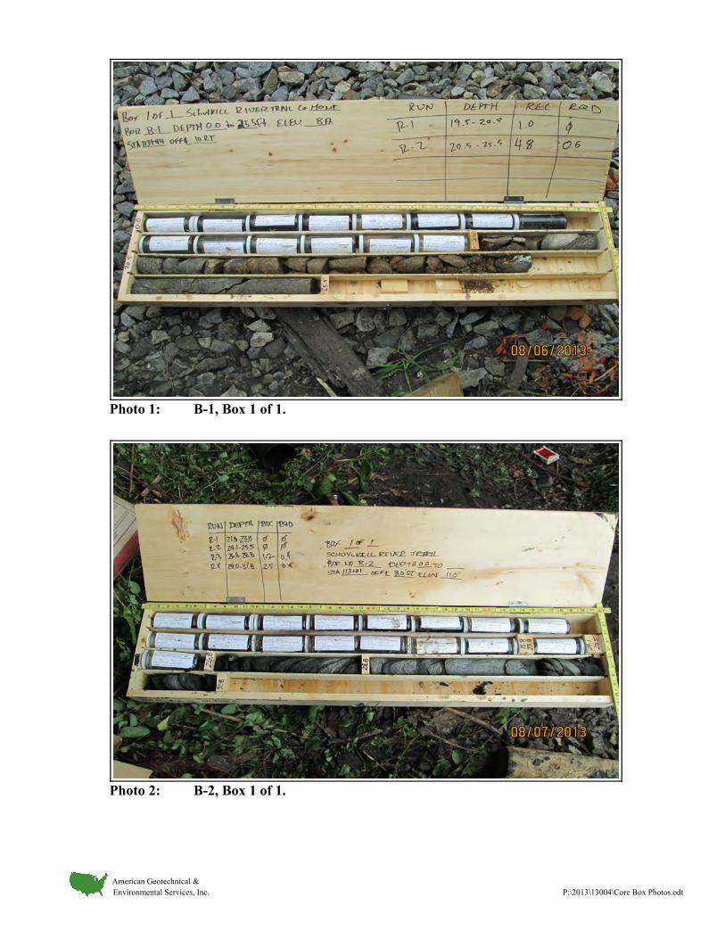
Photo 1: B-1, Box 1 of 1.
Photo 2: B-2, Box 1 of 1.
American Geotechnical & Environmental Services, Inc. P:\2013\13004\Core Box Photos.odt
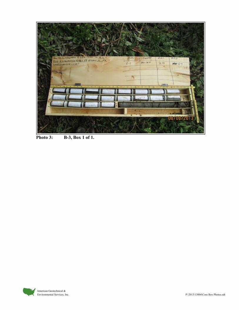
Photo 3: B-3, Box 1 of 1.
American Geotechnical & Environmental Services, Inc. P:\2013\13004\Core Box Photos.odt
APPENDIX E
CONCEPTUAL STRUCTURE PLAN
(Provided by Urban Engineers, Inc.)

OP
ER
AT
OR:
FI
LE
NA
ME:
4/10/2015
PL
OT
TE
D:
$$designfile$$
D-9012
CA
DD (02-90)
RE
VI
SI
ON (10-04)
PREPARED BY:
DESIGN DESIGNATION
APPROVED
PRESIDENT
TOTAL SHEETSDISTRICT COUNTY TOWNSHIP BOROUGH ROUTE SECTION
HIGHWAY CLASSIFICATION
DESIGN SPEED
SHOULDER WIDTH
PAVEMENT WIDTH
DATE:
SCHUYLKILL RIVER DEVELOPMENT CORPORATIONDATE:
SPUR PHA SECTIONSYST/P WO ORG PRG
WBS ELEMENT
P_C
- SHARED USE PATH
- 20 MPH
- 2'-0" (NON-PAVED)
- 12'-0"
FOR
CONSTRUCTION
OF
SCHUYLKILL RIVER DEVELOPMENT CORPORATION
THE SCHUYLKILL RIVER TRAIL EXTENSION - SOUTH STREET TO CHRISTIAN STREET
6-0
PHILADELPHIA PHILADELPHIA
URBAN ENGINEERS, INC.
530 WALNUT STREET, 7TH FL.
PHILADELPHIA, PA 19106
215-922-8080
3
FROM STA. 99+56.00 TO STA. 113+68.00 LENGTH 1412.00 FT, 0.27 MI.
- -
STRUCTURAL DRAWINGS
, PENNSYLVANIAPHILADELPHIA COUNTYIN
APRIL 2015
DISTRICT COUNTY ROUTE SECTION SHEETO
PE
RA
TO
R:
FI
LE
NA
ME:
OF 6-0 PHILADELPHIA
NUMBERREVISIONS DATE BY
REVISION
D-9012
CA
DD (02-90)
RE
VI
SE
D (10-04)
PL
OT
TE
D:
T:\
Projects\
SR
DC -
Schuylkill
Trail at
South
Street\
Dra
wings\
Structures\
SR
T_
Wall_
TS
&L.dgn
4/10/2015
8:45:12
AM
3
CITY OF PHILADELPHIA
1111
98
76
4
3
11
5
10
10
10
1212
12
1213
14
13
11
89 LF OF CONCRETE BULKHEAD
WOODS
CSX RAIL TRACKS
CSX RAIL TRACKS
90'-0" - ALONG FRONT FACE OF WALL
14'-0"
12'-0"
8'-0"
7
89
10 12
WASHOUT
AREA
TREE
WILLOW
TREE
WILLOW
13
12
1111
14
6
4
3
13+50
6.14
10.50
+50
13.50
5.41
7.09
13.90
5 0 5 10 FEET
0 FEETVERTICAL SCALE:
HORIZONTAL SCALE:
ELEVATION
52.5
PLAN
5 0 5 10 FEET
+0.50%
+0.50%-0.50%
LEGEND
NOTES
NUMBER
BORINGSTATION OFFSET
- RETAINING WALL
TABULATION OF STRUCTURE ITEMS
ITEM NO UNIT TOTAL
LS
ITEM
LS
LUMP SUM
LUMP SUM
B-1
B-2
B-3
PVI STA 112+49.98
10
20
10
20
0 0
FRONT FACE RETAINING WALL
B-1 B-2
B-3
9.93' RT
8.85' RT
3.28' RT
113+00 112+00
113+00
AHEAD
STATION
13.00
112+00
FRONT FACE OF WALL
EXISTING GROUND LINE AT
N42°19'02"E
SHARED USE PATH SURVEY & CONSTR �
- R-8 ROCK SCOUR PROTECTION
CSX RIGHT-OF-WAY
SCHUYLKILL RIVER
SUPPLEMENTAL DRAWINGS
DESCRIPTION DWG NO APP DATE
BACKFILL AT STRUCTURES RC-12M 6-1-10
CLASSIFICATION OF EARTHWORK FOR STRUCTURES RC-11M 6-1-10
BRIDGE DRAINAGE
REINFORCEMENT BAR FABRICATION DETAILS BC-736M 5-18-12
5-18-12BC-751M
8212-0001
8255-0001
BORING LOCATIONS
113+32.25
112+87.81
112+48.45
10
11
11
2. RAILING WILL BE CHOSEN IN FINAL DESIGN.
SEE SHEET 2.
1. FOR GENERAL NOTES AND TYPICAL SECTION,
(AS-DESIGNED FOUNDATION PROVIDED)
DESIGN OF RETAINING WALL
RETAINING WALL
CONSTRUCTION OF SOLDIER PILE
SHARED USE PATH
SHARED USE PATH
HORIZONTAL ALIGNMENT
VERTICAL ALIGNMENT
EL
EV 10.54
PV
C
ST
A 112
+19.98
EL
EV 10.54
PV
T
ST
A 112
+79.98
EL
EV 10.99
PV
T
ST
A 113
+69.00
TANGENT
BC-734M 10-26-10
BC-701M 5-18-12PROTECTIVE FENCE
ANCHOR SYSTEMS
- RAILING
10.81
10.69
11.19
10.56
11.06
10.44
10.94
10.39
10.44
10.56
ELEVATION (TYP)
GUTTERLINE
CAP ELEVATION (TYP)
TOP OF WALL
VC 60.00'
ELEVATION (TYP)EXISTING GROUND LINE
SHARED USE PATH SURVEY & CONSTR �
- AS DRILLED TEST BORING LOCATION
5
10
-10 -10
GUTTERLINE
5
10
PG ELEV 10.47
STA 112+49.85
SURVEY & CONSTR �
BEGIN WALL
PG ELEV 10.84
STA 113+39.85
SURVEY & CONSTR �
END WALL
CAISSON ELEV -3.00
ESTIMATED TOP OF
ELEV 10.39
Proposed contours are on Level=50.
DEP Permitting level contains High Water info. Can be turned off for TS&L only drawing.
ESTIMATED TOP OF WALL
2
CSX RIGHT-OF-WAY
CONCEPTUAL STRUCTURE PLAN
SCHUYLKILL RIVER TRAIL EXTENSION
RAILING
RAILING
~CONCRETE CAP
2'-0" x 2'-3" CAST-IN-PLACE
113+68

8'-0"
90'-0"
2'-0"
6"
(M
AX.
HEI
GH
T)
13'-8•
"
(V
ARI
ES)
12'-2
…"
TO 19'-0"
6"
MIN
1'-0"
(6'-0"
MI
N.)
VA
RI
ES
5'-0"
MI
N.
MI
N.
3'-6"
9"
MIN
1'-0"
2'-0"
2'-3"
(TYP)
3"
TYPICAL SECTION
1%
FINISHED GRADE
FINISHED GRADE
CONSTR & SURVEY �
SHARED USE PATH
GUTTERLINE
GENERAL NOTES
� SOLDIER PILE & CAISSON
FOUNDATION DRAIN
6" | STRUCTURE
1 0 1 2 3 FEET
FOUNDATIONS
DATA POINTWORK
W.P. STATION OFFSET
1
2
LOCATION
NORTHING EASTING
COORDINATES
STAKE-OUT PLAN
NOT TO SCALE
SURVEY & CONSTR. �
SHARED USE PATH
A A
PRECAST CONCRETE PANEL
~
FRONT FACE RETAINING WALL
VERTICAL
FOUNDATION
2'-6" | CAISSON
N42°19'02"E
112+49.85
113+39.85
233577.6293 2686987.9173
FRONT FACE STEEL SOLDIER PILE @ �
W.P. 2W.P. 1
10.00' LT
10.00' LT
ELEV = -15.2 TO -22.0 (VARIES)
EST. BOT. OF CAISSON
AGGREGATE
#57 COARSE~
END WALL BEGIN WALL
233644.1780 2687048.5083
R-8 ROCK LINING
ELEV -10.2 TO -17.0 (VARIES)
EST. TOP OF ROCK
ELEV -3.0
EST. TOP OF CAISSON
ELEV 4.10
MEAN HIGH WATER
1.5
1
GROUND LINE
APPROX EXISTING
GENERAL NOTES & TYPICAL SECTION
3
RAILING
STEEL SOLDIER PILE
PA ONE CALL SERIAL NUMBER 20130491115, 20130491116, & 20130491117. (1-800-242-1776)
UTILITES IN ACCORDANCE WITH SECTIONS 105.06 AND 107.12.
18. COORDINATE, LOCATE, AND CONDUCT ALL WORK RELATED TO PUBLIC AND PRIVATE
UNLESS SPECIFIED.
17. WELDING OF REINFORCEMENT BARS DURING FABRICATION AND CONSTRUCTION IS NOT PERMITTED
BC-736M, UNLESS OTHERWISE INDICATED.
16. PROVIDE MINIMUM EMBEDMENT AND SPLICE LENGTHS IN ACCORDANCE WITH STANDARD DRAWING
15. ALL DIMENSIONS ARE HORIZONTAL UNLESS NOTED OTHERWISE.
PROCEDURES, INCLUDING BRACING AND NECESSARY DETAILS FOR APPROVAL PRIOR TO CONSTRUCTION.
RETAINING WALL INCLUDING POST LOCATIONS WITH SHOP DRAWINGS FOR APPROVAL. SUBMIT ERECTION
14. PROVIDE SHOP DRAWINGS IN ACCORDANCE WITH SECTION 105.02. SUBMIT DETAILED LAYOUT OF
13. PROVIDE NO. 57 AGGREGATE DRAINAGE DETAILS AS INDICATED.
STEEL BARS AT NO ADDITIONAL COST TO THE DEPARTMENT.
12. GALVANIZED REINFORCING STEEL BARS MAY BE SUBSTITUTED FOR EPOXY COATED REINFORCING
11. USE EPOXY COATED REINFORCEMENT BARS IN PRECAST CONCRETE PANELS.
REINFORCEMENT BARS IS INDICATED.
NOT USE RAIL STEEL A996/A996M REINFORCEMENT BARS WHERE BENDING OR WELDING OF THE
INCREASE IN CROSS SECTIONAL AREA, IF APPROVED BY THE OWNER REPRESENTATIVE. DO
SPECIFIED. GRADE 40 REINFORCING STEEL BARS MAY BE SUBSTITUTED WITH A PROPORTIONAL
A996/A996M OR A706/A706M. DO NOT WELD GRADE 60 REINFORCING STEEL BARS UNLESS
10. PROVIDE GRADE 60 REINFORCING STEEL BARS THAT MEET THE REQUIREMENTS OF A615/A615M-
ADDITIONAL COST TO THE OWNER.
9. A HIGHER CLASS CONCRETE MAY BE SUBSTITUTED FOR A LOWER CLASS CONCRETE AT NO
8. UTILIZE TYPE II CEMENT FOR ALL CONCRETE STRUCTURES.
7. USE CLASS A CEMENT CONCRETE FOR DRILLED CAISSON FOUNDATIONS.
6. USE CLASS AA CEMENT CONCRETE IN PRECAST CONCRETE PANELS.
5. CHAMFER EXPOSED CONCRETE EDGES 1"x1", EXCEPT AS NOTED OTHERWISE.
4. PROVIDE 2 IN. CONCRETE COVER ON REINFORCEMENT BARS, EXCEPT AS NOTED.
THE LRFD METHOD DESIGN LOAD: LIVE LOAD SURCHARGE PER DESIGN MANUAL, PART 4.
PENNDOT DESIGN MANUAL, PART 4, MAY 2012 EDITION. DESIGN IS IN ACCORDANCE WITH
AASHTO LRFD BRIDGE DESIGN SPECIFICATIONS (2010) AND AS SUPPLEMENTED BY THE
3. DESIGN SPECIFICATIONS:
OTHERWISE.
AASHTO M270/M270M GRADE 50 (ASTM A709/A709M GRADE 50) EXCEPT WHEN NOTED
2. PROVIDE STRUCTURAL STEEL (GALVANIZED AND COLOR COATED) CONFORMING TO
USE AWS D1.1/D1.1M-2008 FOR WELDING NOT COVERED IN AASHTO/AWS D1.5/D1.5M-2008.
AASHTO/AWS D1.5/D1.5M BRIDGE WELDING CODE (2008) AND CONTRACT SPECIAL PROVISIONS.
DEPARTMENT OF TRANSPORTATION SPECIFICATIONS, PUBLICATION 408/2011-5,
1. PROVIDE MATERIALS AND PERFORM WORK IN ACCORDANCE WITH PENNSYLVANIA
SEE DETAIL A, THIS SHEET.
2'-0" x 2'-3" CAST-IN-PLACE CONCRETE CAP,
9. BLASTING IS NOT PERMITTED AS A METHOD OF EXCAVATION.
COARSE AGGREGATE.
8. FILL THE GAP BETWEEN PERMANENT LAGGING AND TEMPORARY TIMBER LAGGING WITH AASHTO NO. 57
SUBBASE (OGS) CRITERION.
7. STRUCTURE BACKFILL MAY CONSIST OF MATERIAL MEETING ASSHTO NO. 57 OR PENNDOT OPEN GRADED
BEARING MATERIAL.
6. BACKFILL CAISSON BOREHOLE WITHIN 24-HOURS AFTER DRILLING TO LIMIT THE DETERIORATION OF THE
TO PREVENT CAVED MATERIAL FROM CONTAMINATING THE CONCRETE.
UTILIZED, MAINTAIN CONCRETE LEVELS ABOVE THE BOTTOM OF CASING AT ALL TIMES DURING EXTRACTION
5. TEMPORARY CASING MAY BE REQUIRED TO MAINTAIN AN OPEN BOREHOLE. IF TEMPORARY CASING IS
4. PROVIDE GALVANIZED PILE FOR CORROSION PROTECTION.
OF CONTAMINATED MATERIAL HANDLING."
3. ALL EXCAVATED MATERIAL SHALL BE HANDLED IN ACCORDANCE WITH SPECIFICATION "026113 - EXCAVATION
BE REQUIRED FOR CONSTRUCTION OF SUBSTRUCTURE UNITS.
2. TEMPORARY SHORING AND/OR STREAM DIVERSION BARRIERS ALONG WITH DEWATERING TECHNIQUES MAY
EXCAVATIONS IN ACCORDANCE WITH OSHA REQUIREMENTS.
1. THE CONTRACTOR IS RESPONSIBLE FOR THE STABILITY OF ALL EXCAVATED SLOPES. PERFORM ALL
TIMBER LAGGING
SECTION A-A
1 0 1 2 FEET
OF EXCAVATION)FOR TEMPORARY SUPPORTMAY SELECT OTHER SYSTEMTIMBER LAGGING (CONTRACTOR
~
~
CAISSON FOUNDATION
STEEL ANGLE (TYP)
STEEL SOLDIER PILE
PRECAST CONCRETE PANEL
(W.P. LOCATION)
1 0 1 2 FEET
DETAIL A
#4 @ 12"
#5
DISTRICT COUNTY ROUTE SECTION SHEETO
PE
RA
TO
R:
FI
LE
NA
ME:
OF 6-0 PHILADELPHIA
NUMBERREVISIONS DATE BY
REVISION
D-9012
CA
DD (02-90)
RE
VI
SE
D (10-04)
PL
OT
TE
D:
T:\
Projects\
SR
DC -
Schuylkill
Trail at
South
Street\
Dra
wings\
Structures\
SR
T-
Gen
Notes
&
Typ
Sect.dgn
4/10/2015
8:55:25
AM
3
CITY OF PHILADELPHIA

APPENDIX F
GENERALIZED GEOLOGIC PROFILE

PROJECT:
DRAWN:
DATE:
SCALE:
FIGURE:
PLT
:C
KD
:Q
A\Q
C:
SCHUYKILL RIVER TRAIL EXTENSION
SOUTH STREET TO CHRISTIAN STREET
PHILADELPHIA COUNTY, PENNSYLVANIA
GENERALIZED GEOLOGIC
PROFILE A-A
13004
RJE
SEP. 2013
AS SHOWN
RJE
SC
SY
Y
File: M
:\_2013\004\exhibits\profile\13004_gpro.dw
g
Date: 4/10/15
AMERICAN GEOTECHNICAL &ENVIRONMENTAL SERVICES, INC.
Corporate Office: Canonsburg, PA (724) 916-0300
Branch Offices: King of Prussia, PA (610) 354-0333
Holidaysburg, PA (814) 696-7890
Baltimore, MD (410) 814-7552
www.agesinc.com

APPENDIX G
GEOTECHNICAL ANALYSIS
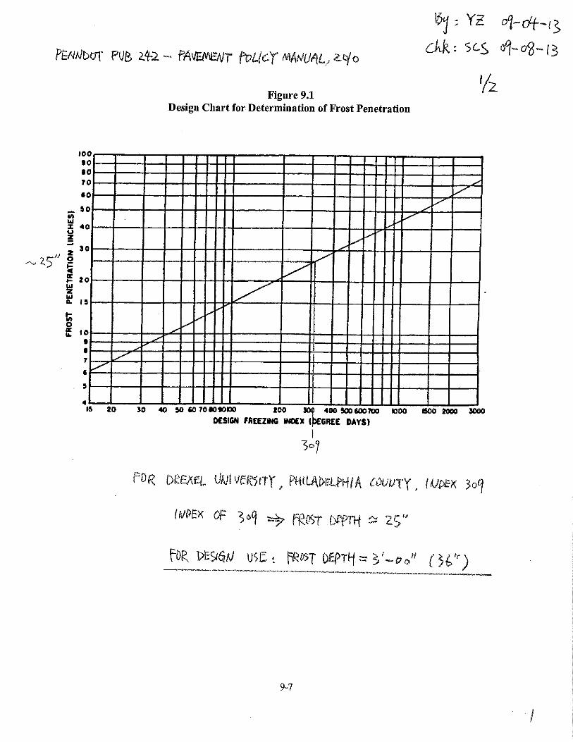
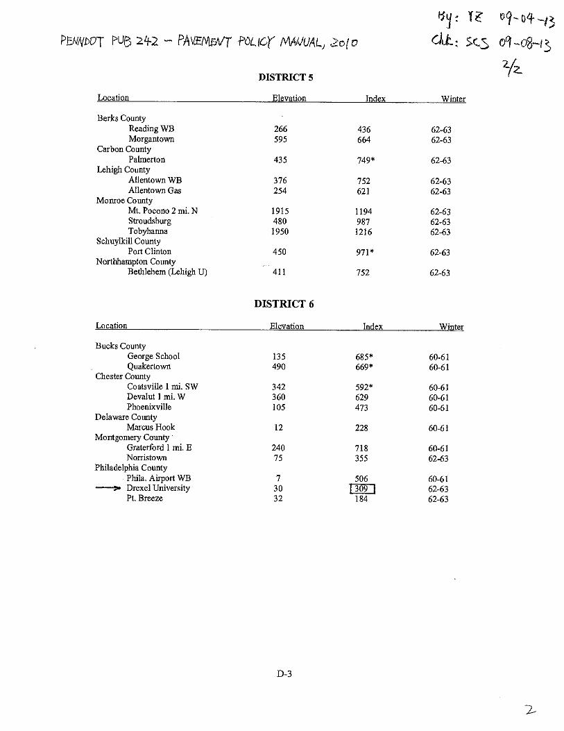
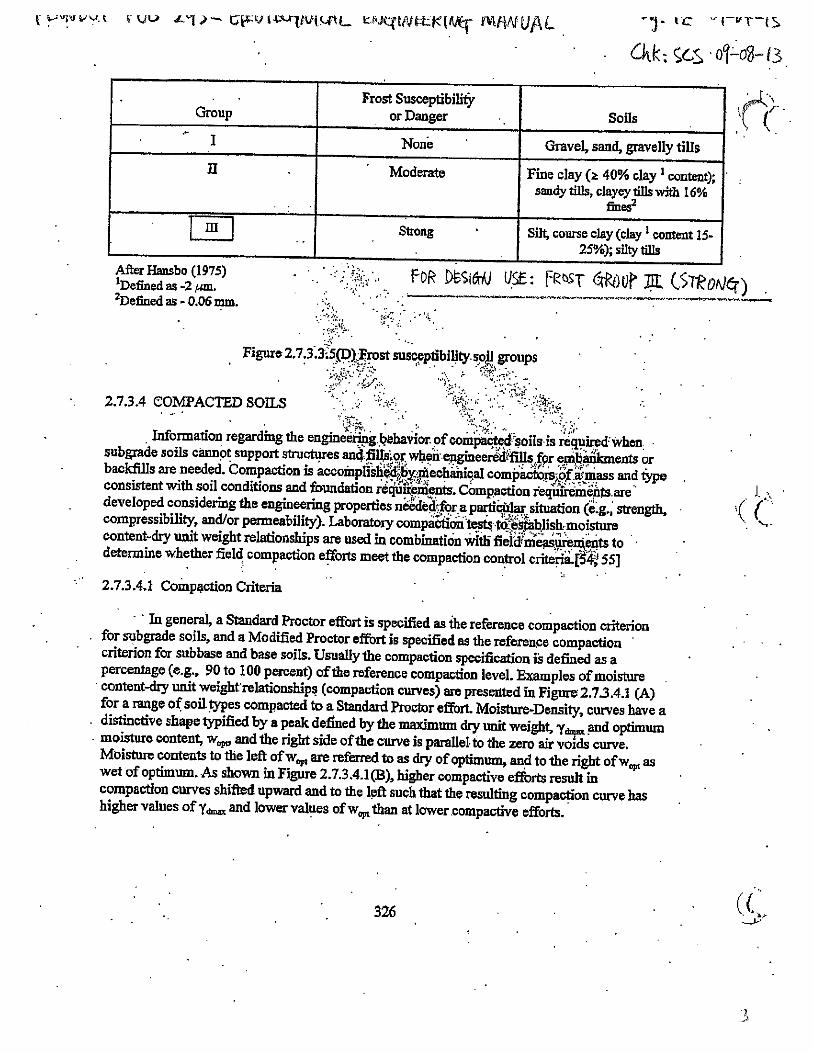
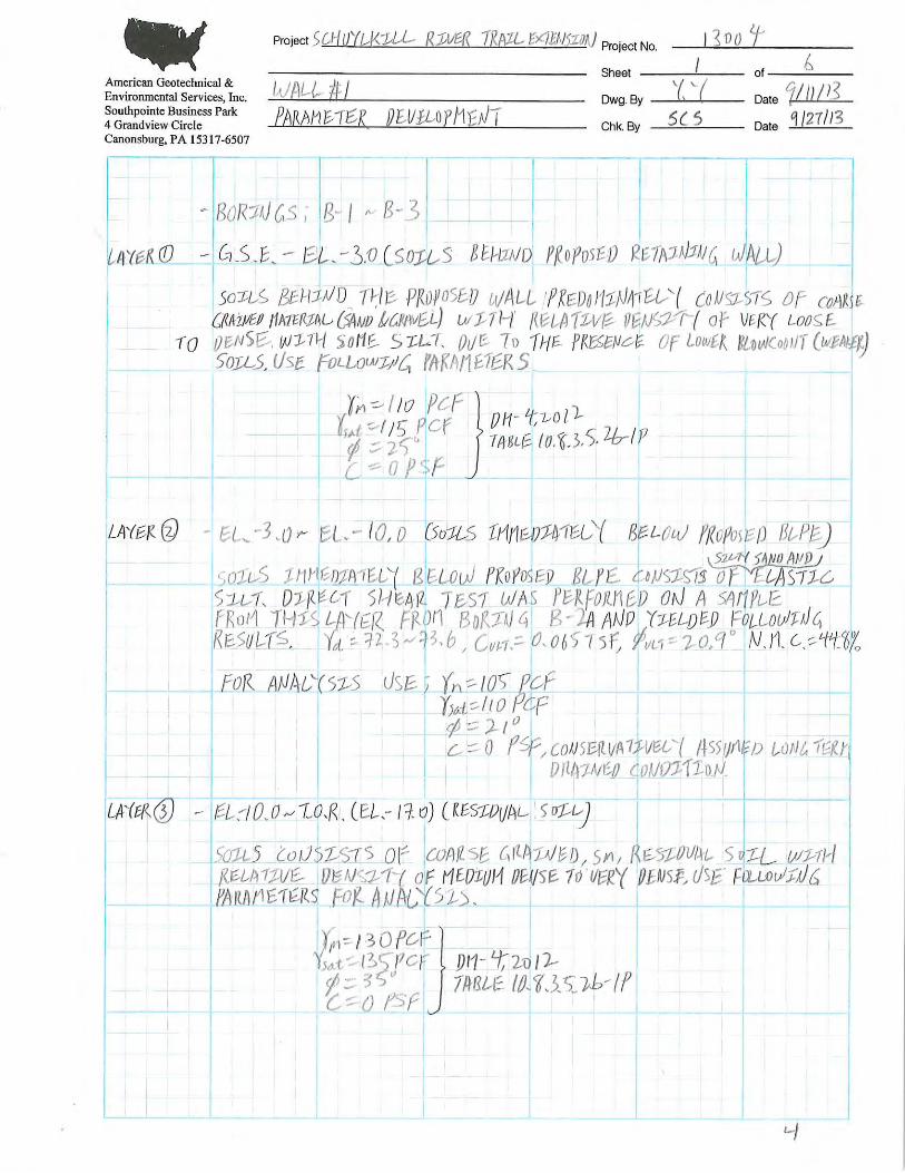
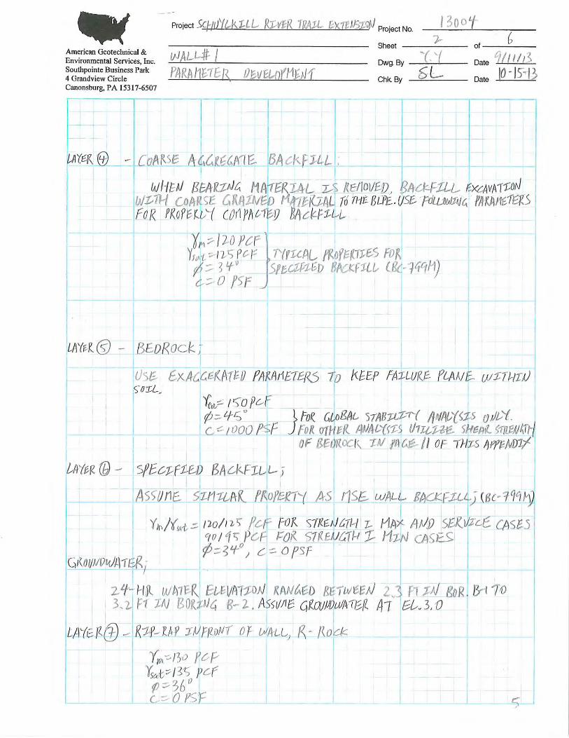
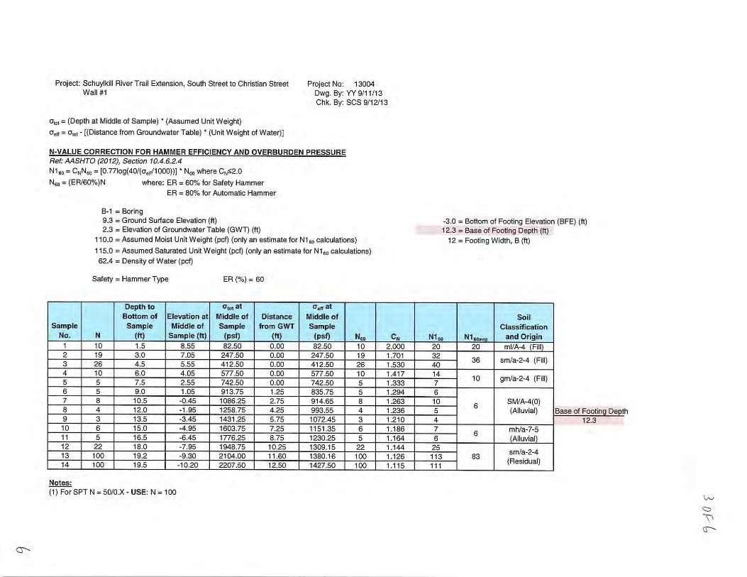
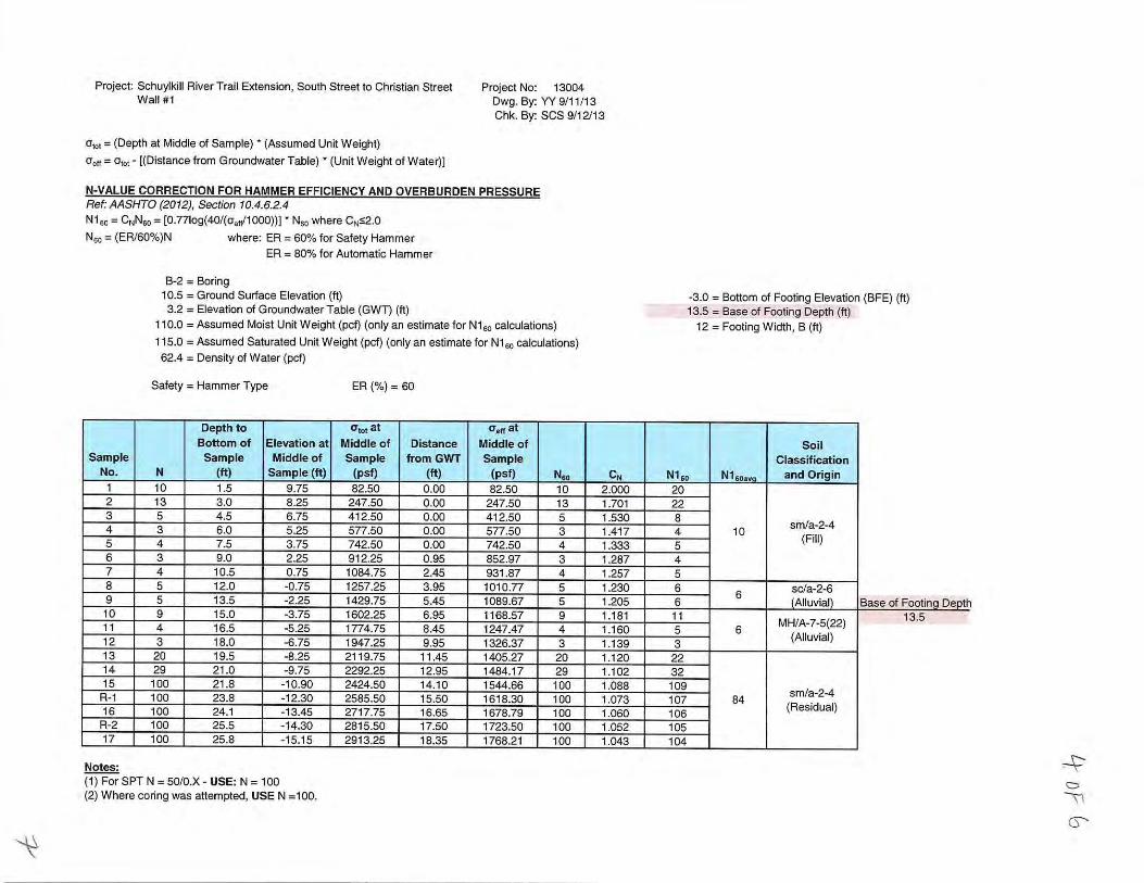
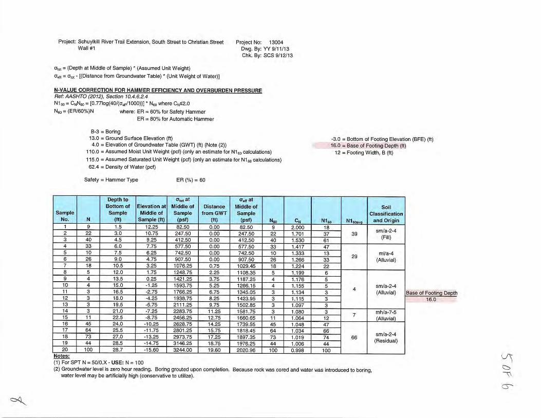

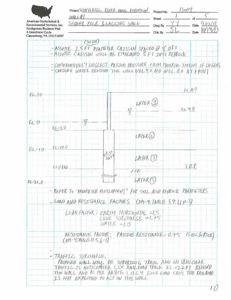
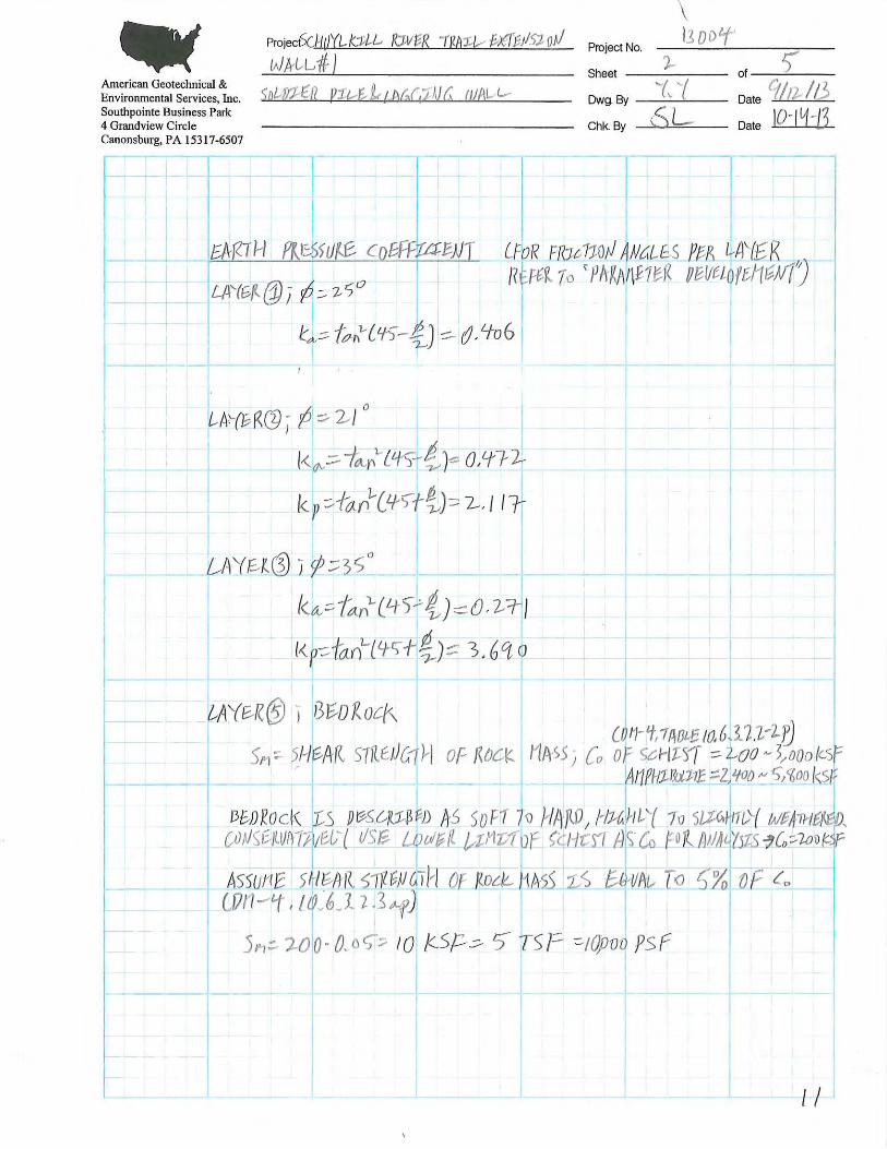
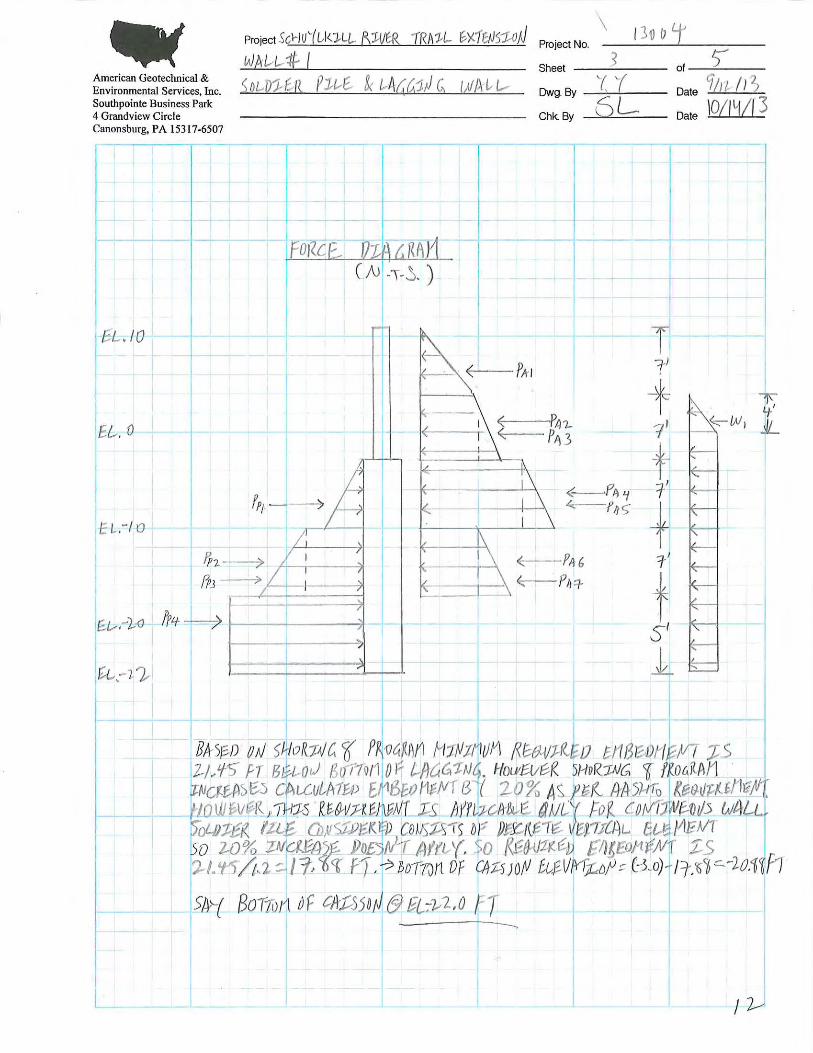
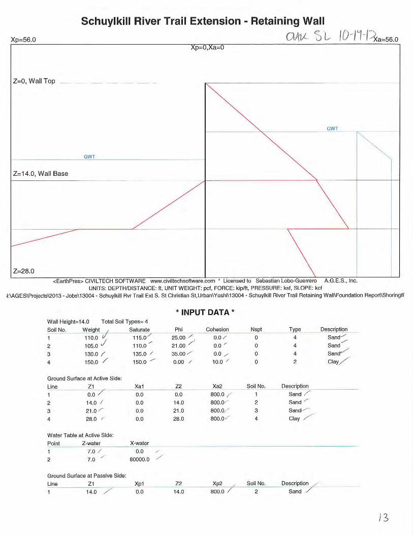

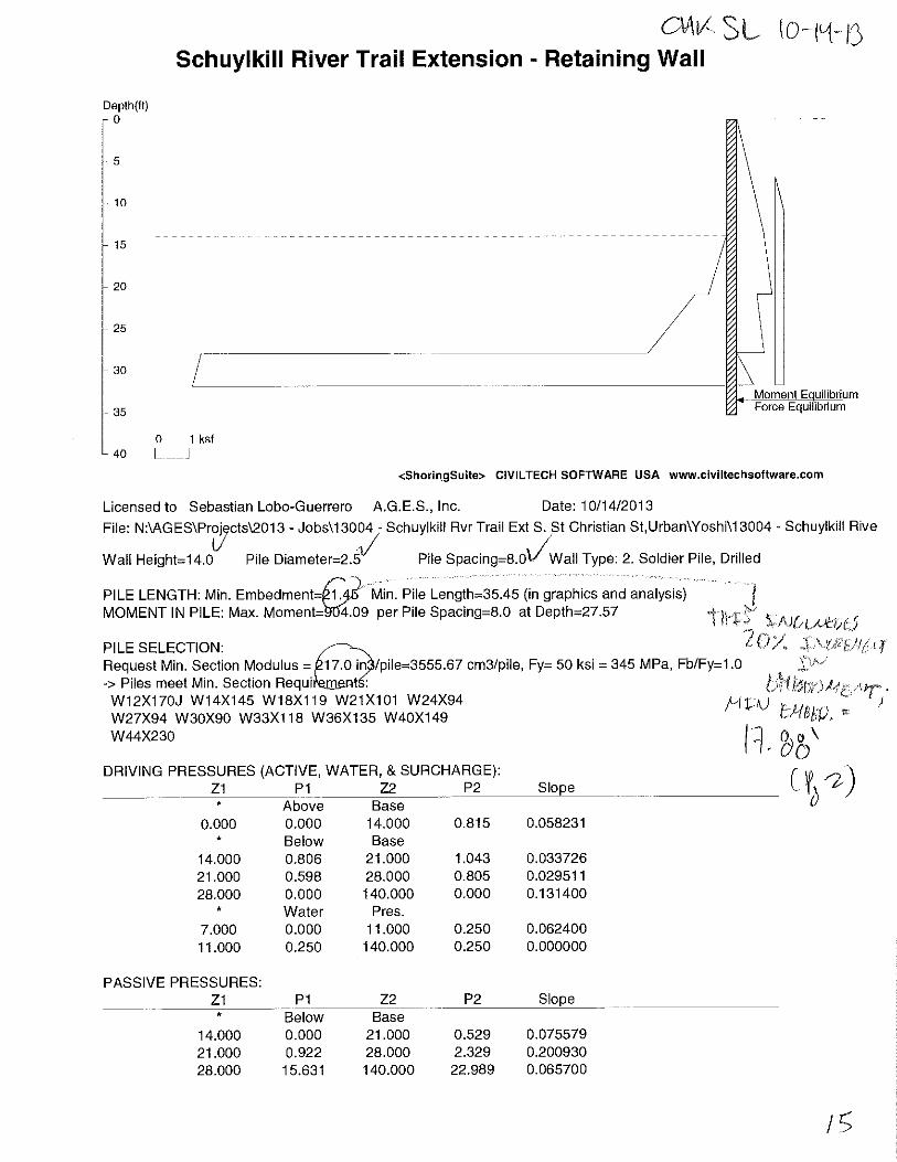
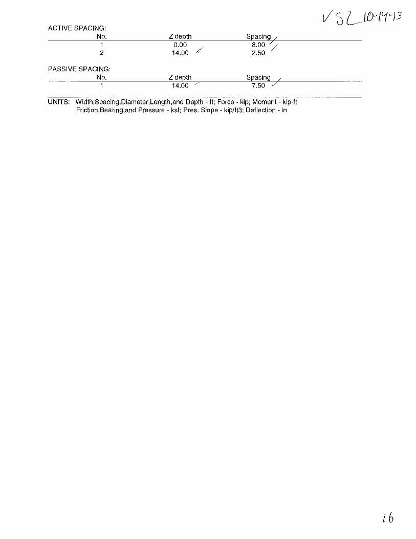
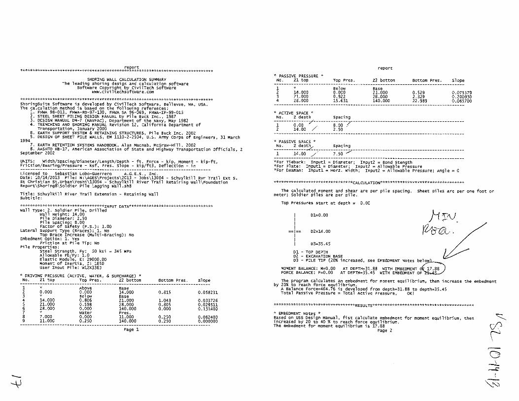

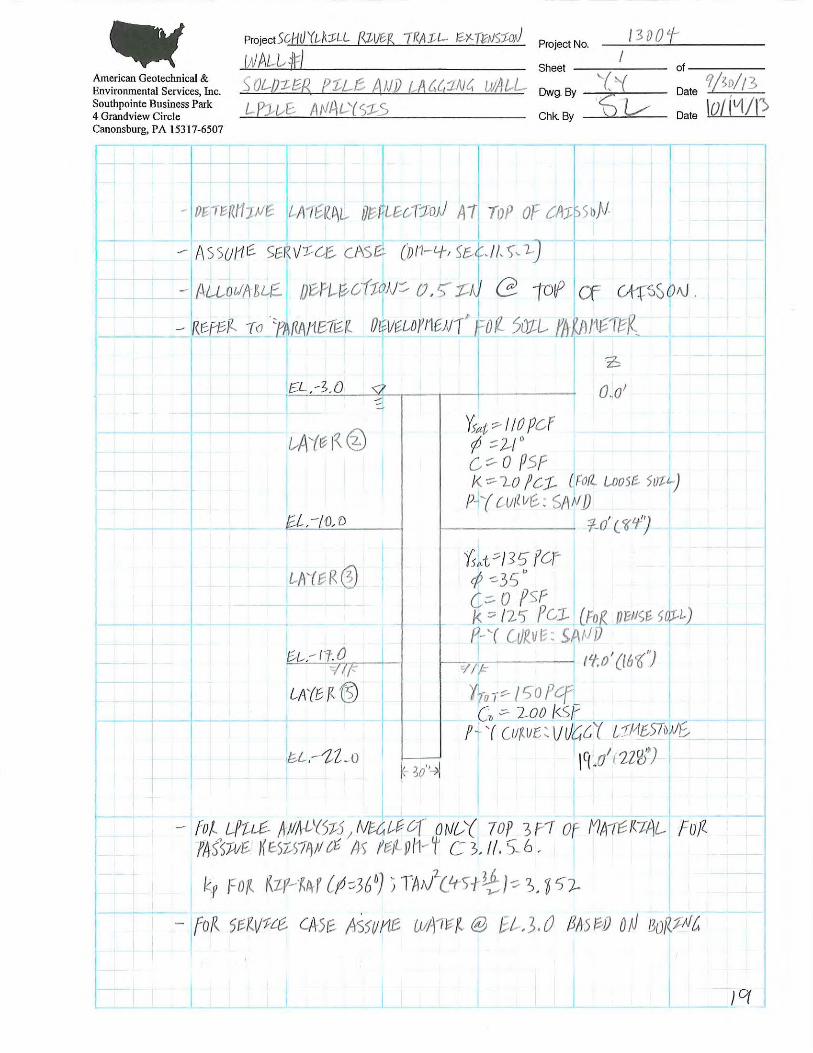
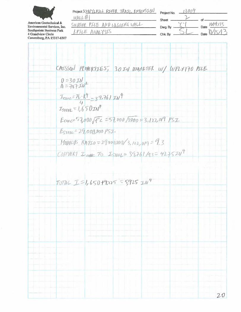

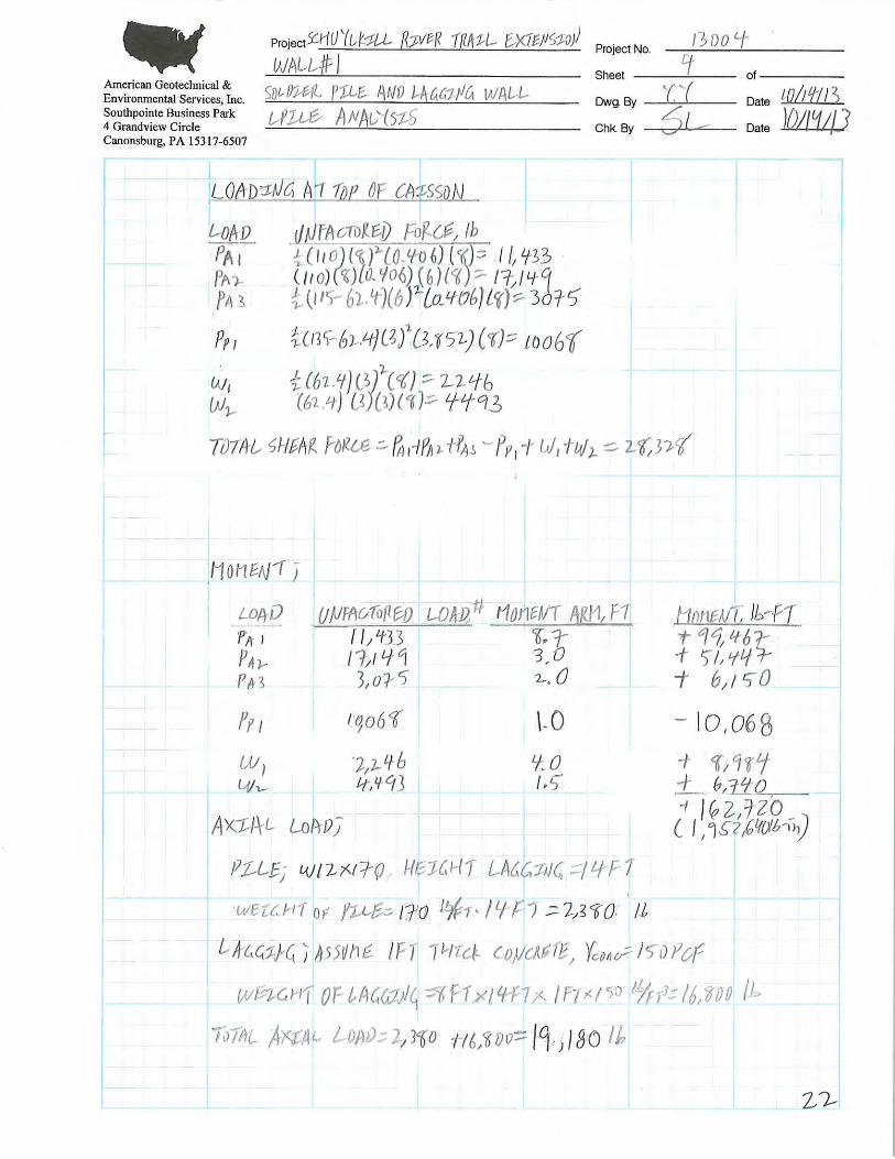

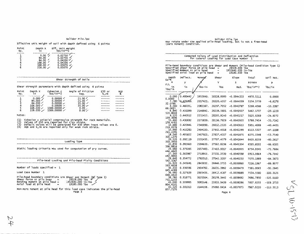
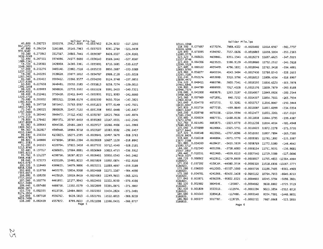
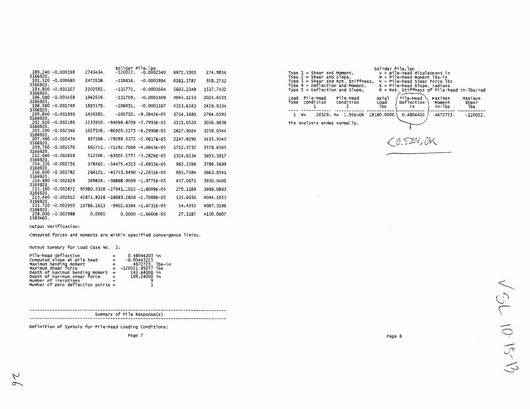
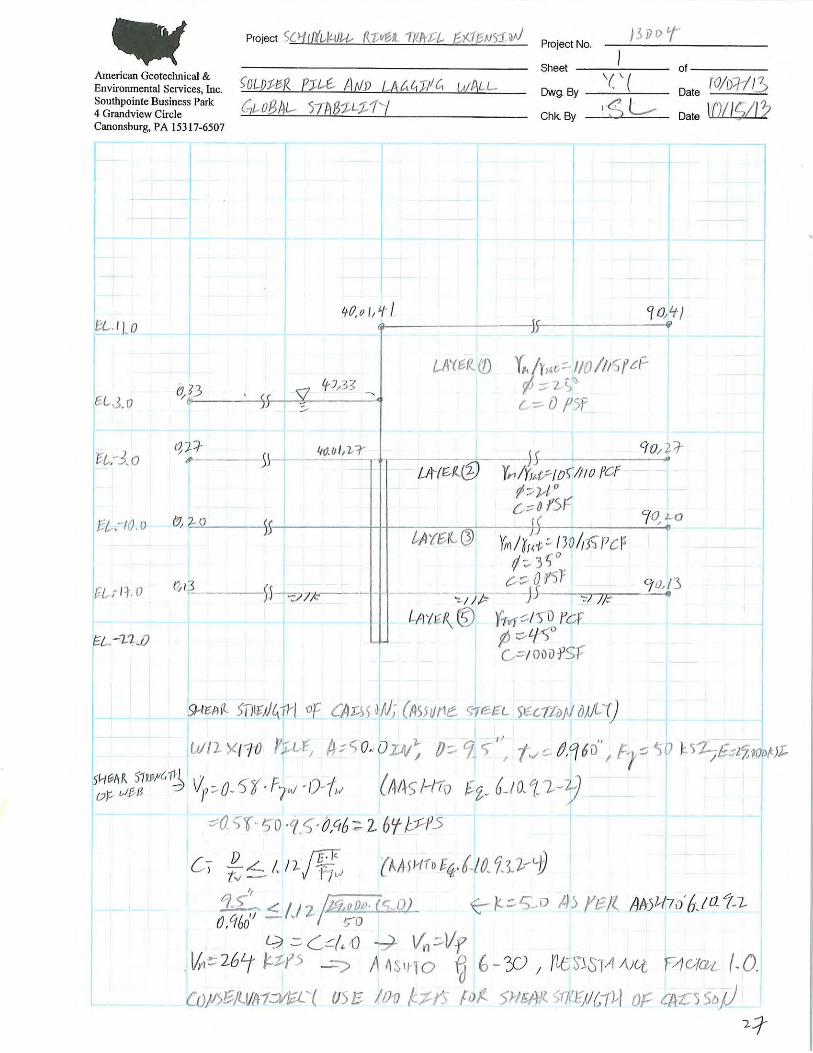
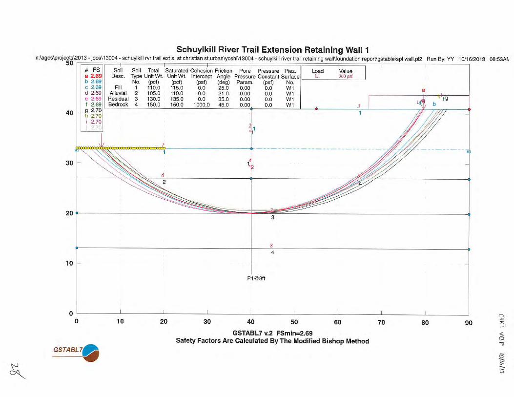
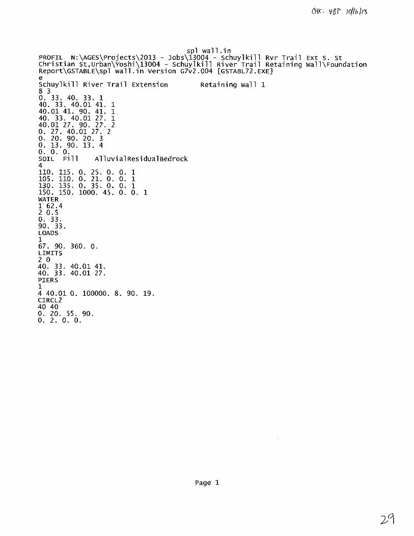

APPENDIX H
SITE PHOTOS
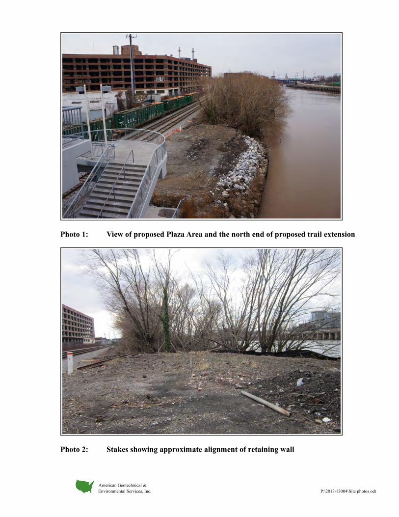
Photo 1: View of proposed Plaza Area and the north end of proposed trail extension
Photo 2: Stakes showing approximate alignment of retaining wall
American Geotechnical & Environmental Services, Inc. P:\2013\13004\Site photos.odt
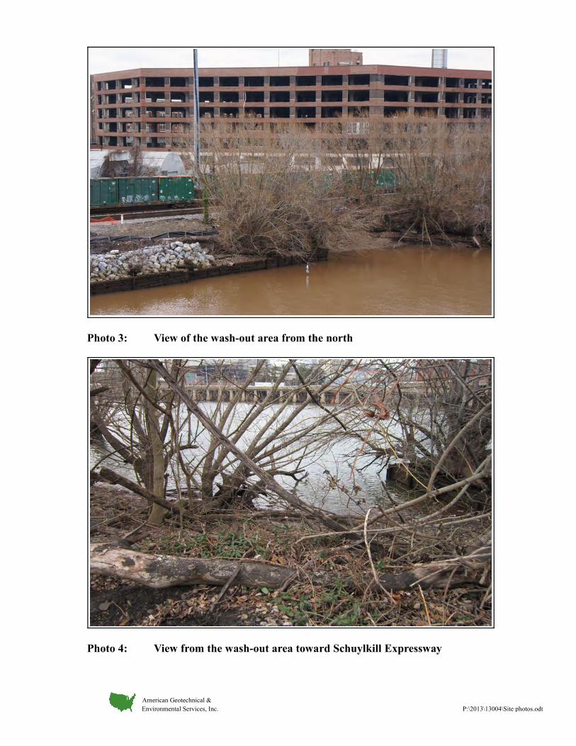
Photo 3: View of the wash-out area from the north
Photo 4: View from the wash-out area toward Schuylkill Expressway
American Geotechnical & Environmental Services, Inc. P:\2013\13004\Site photos.odt
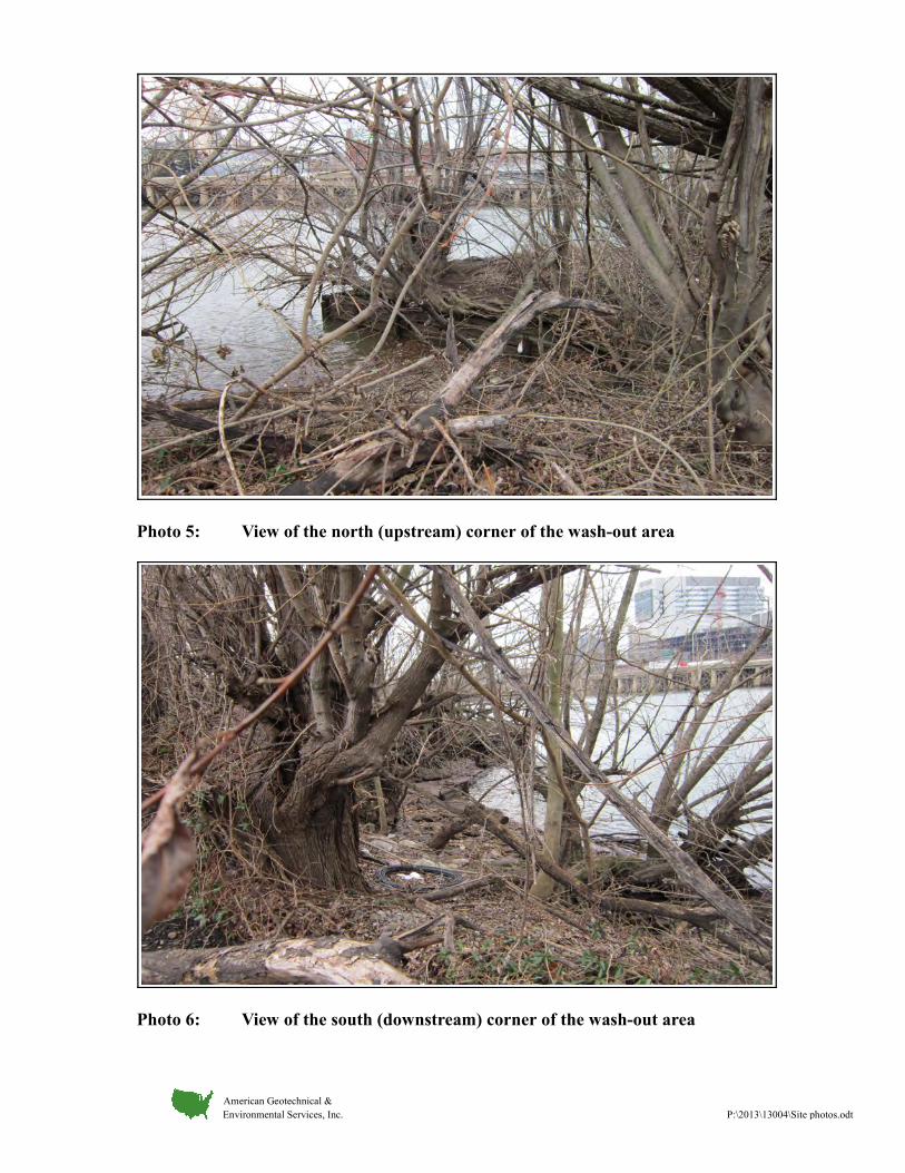
Photo 5: View of the north (upstream) corner of the wash-out area
Photo 6: View of the south (downstream) corner of the wash-out area
American Geotechnical & Environmental Services, Inc. P:\2013\13004\Site photos.odt
APPENDIX I
ROADWAY CROSS-SECTIONS
(Provided by Urban Engineers, Inc.)
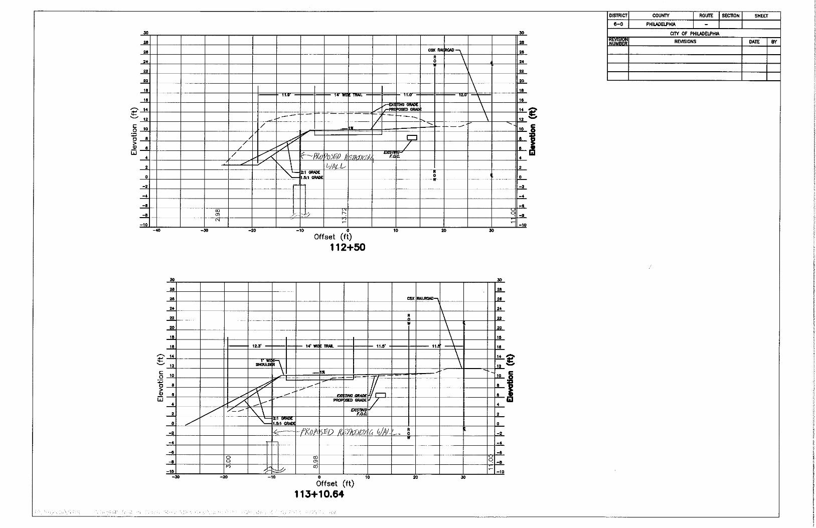
APPENDIX J
EXISTING BORINGS
(Provided by URS Corporation)
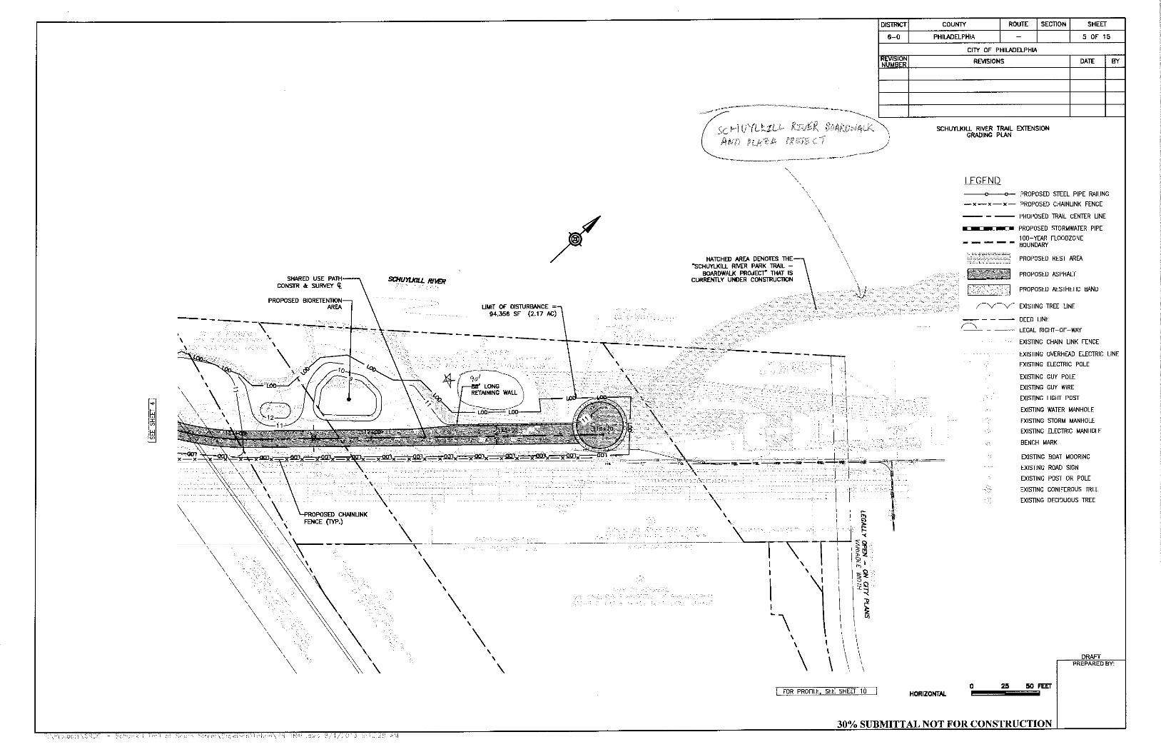
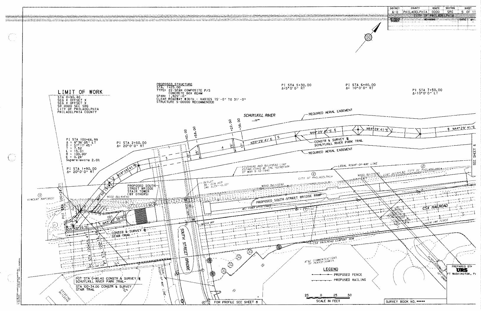
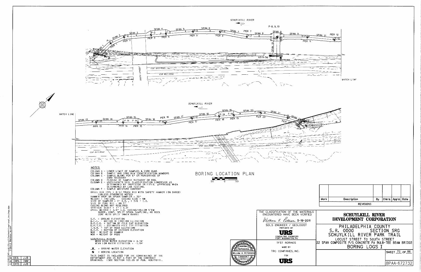
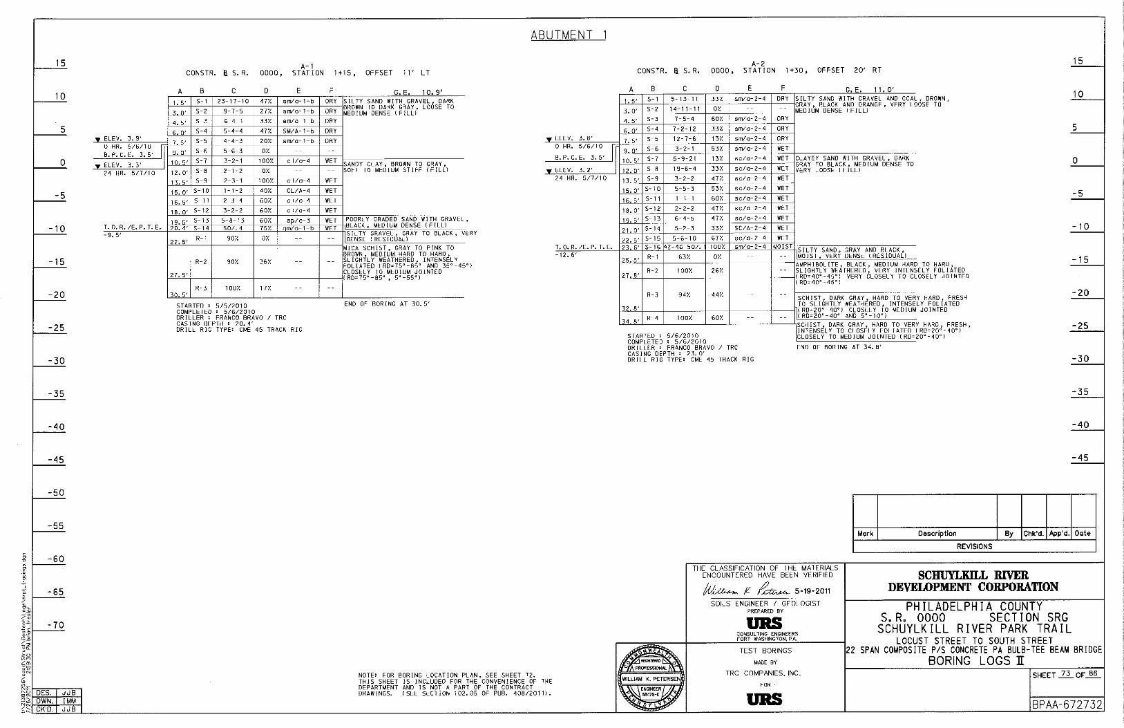
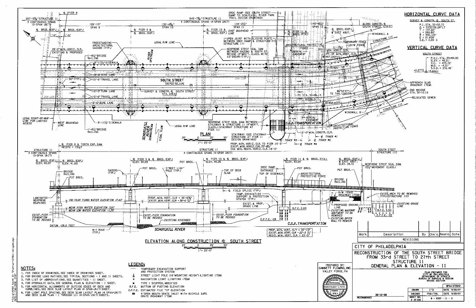
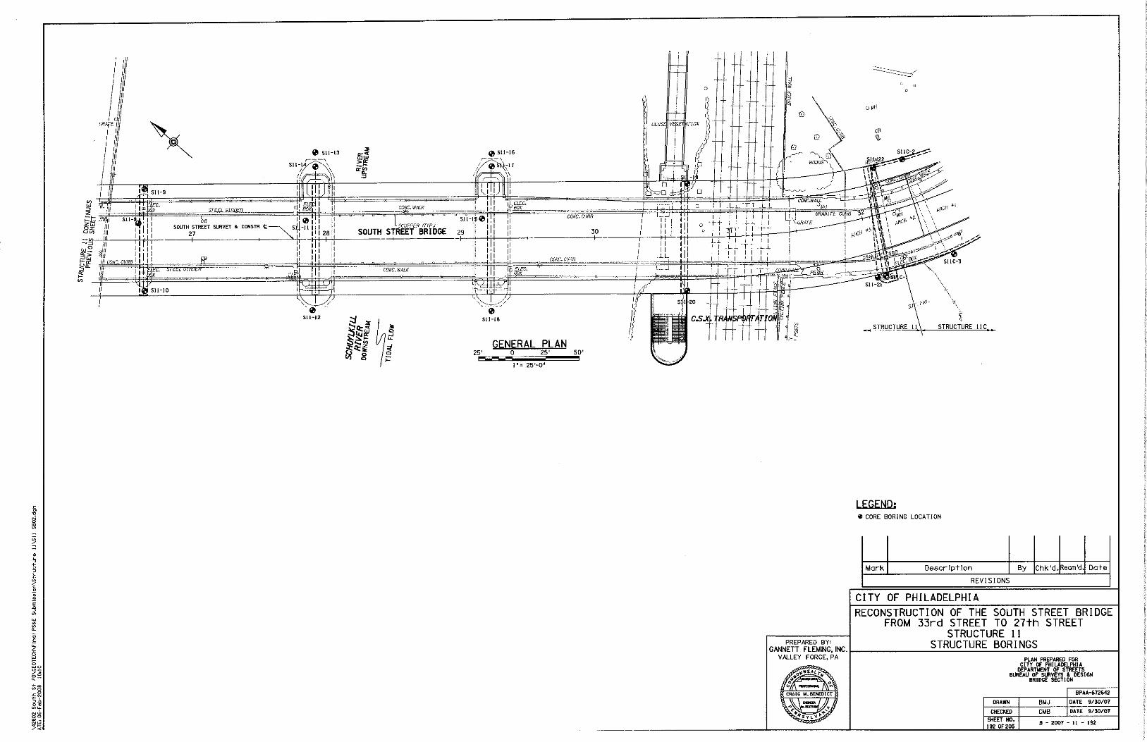
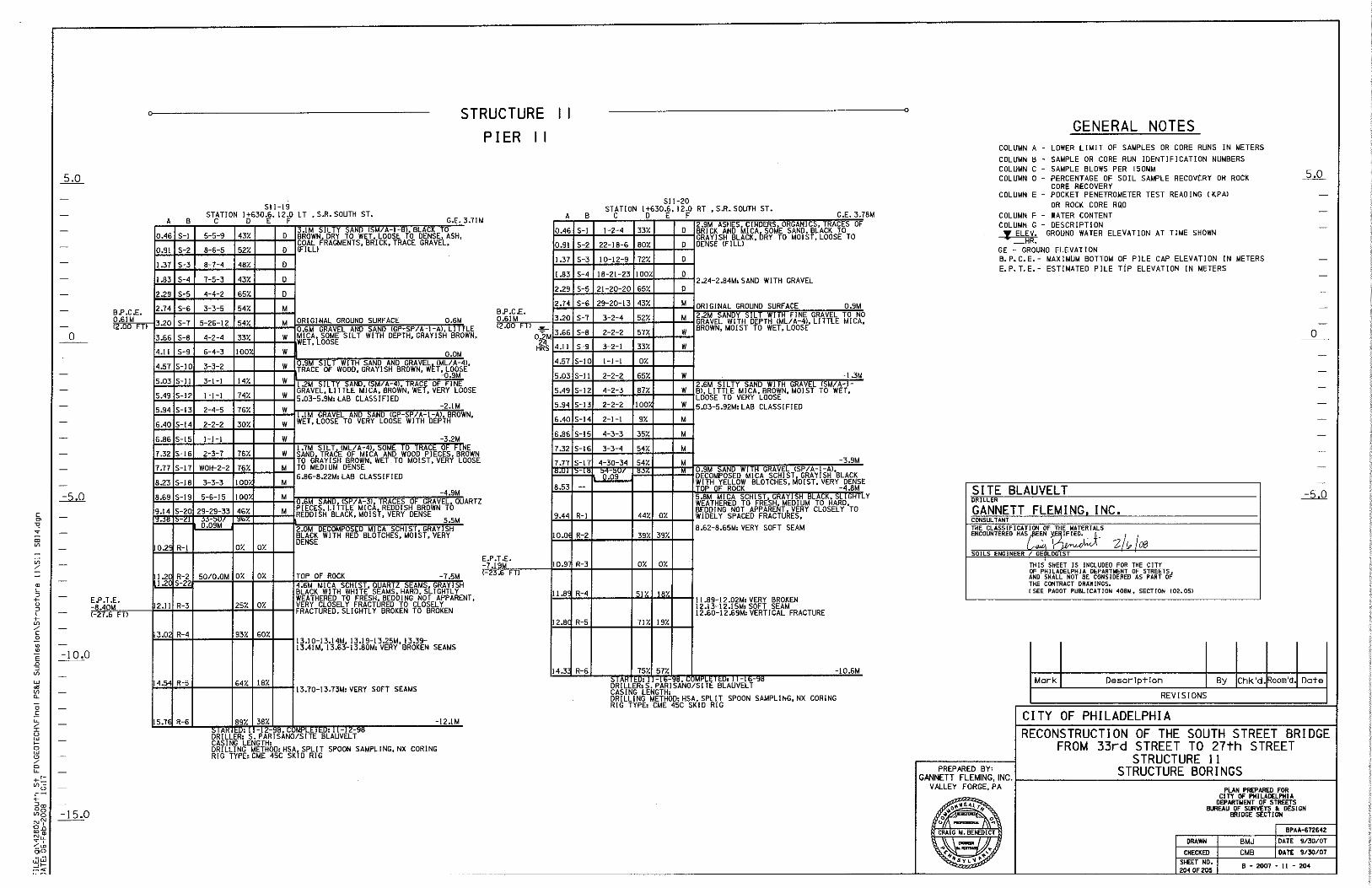
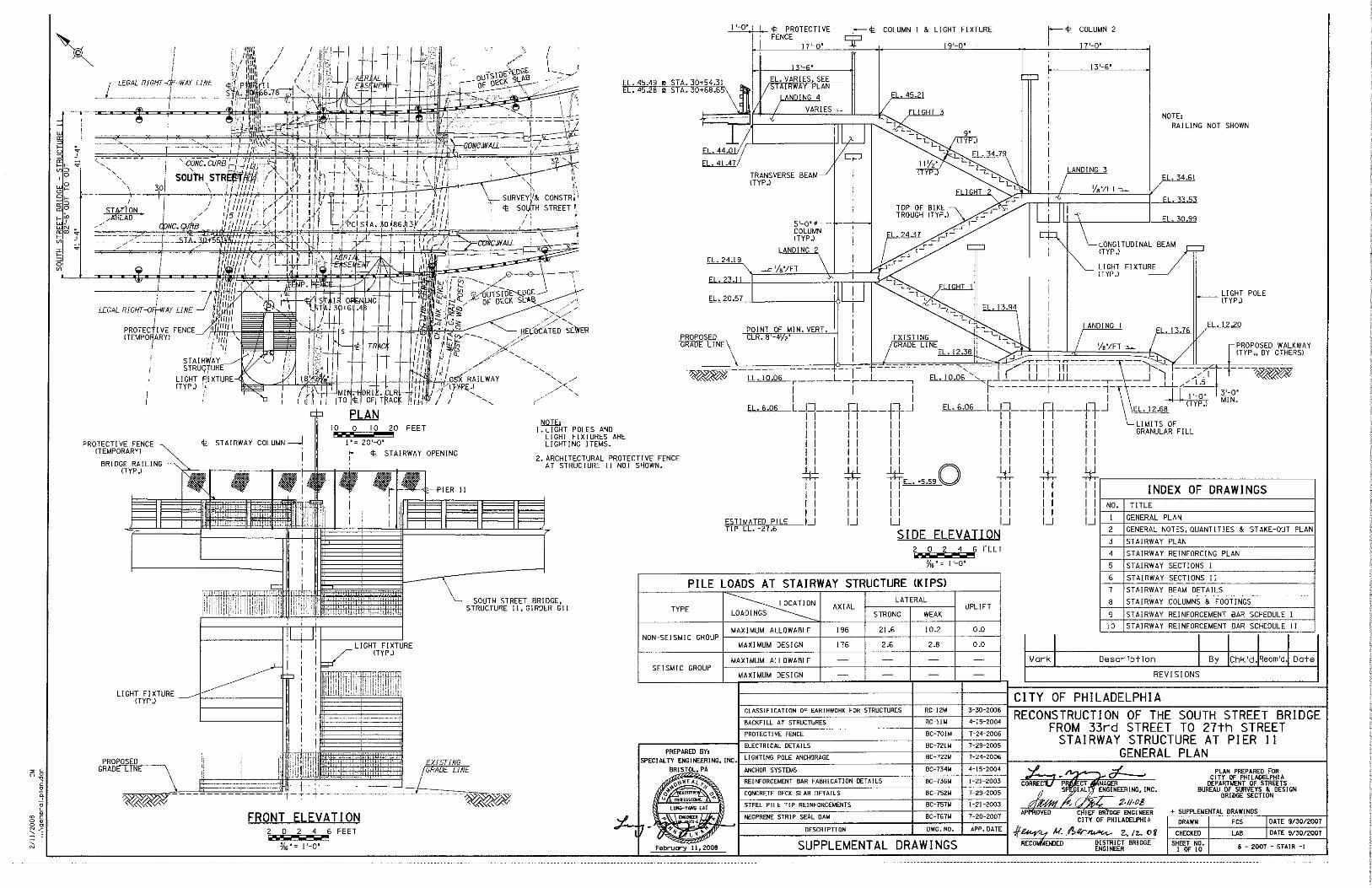
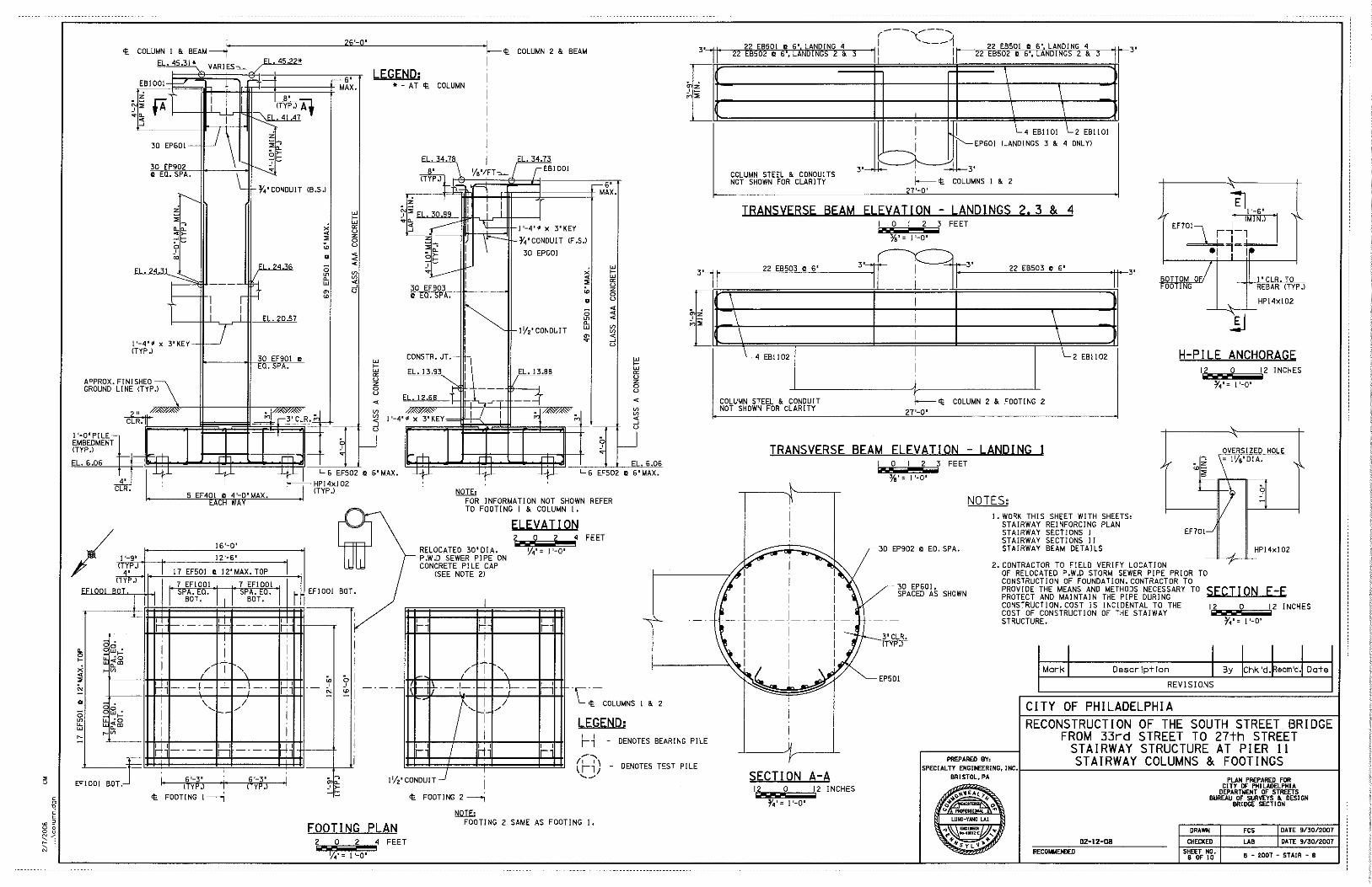
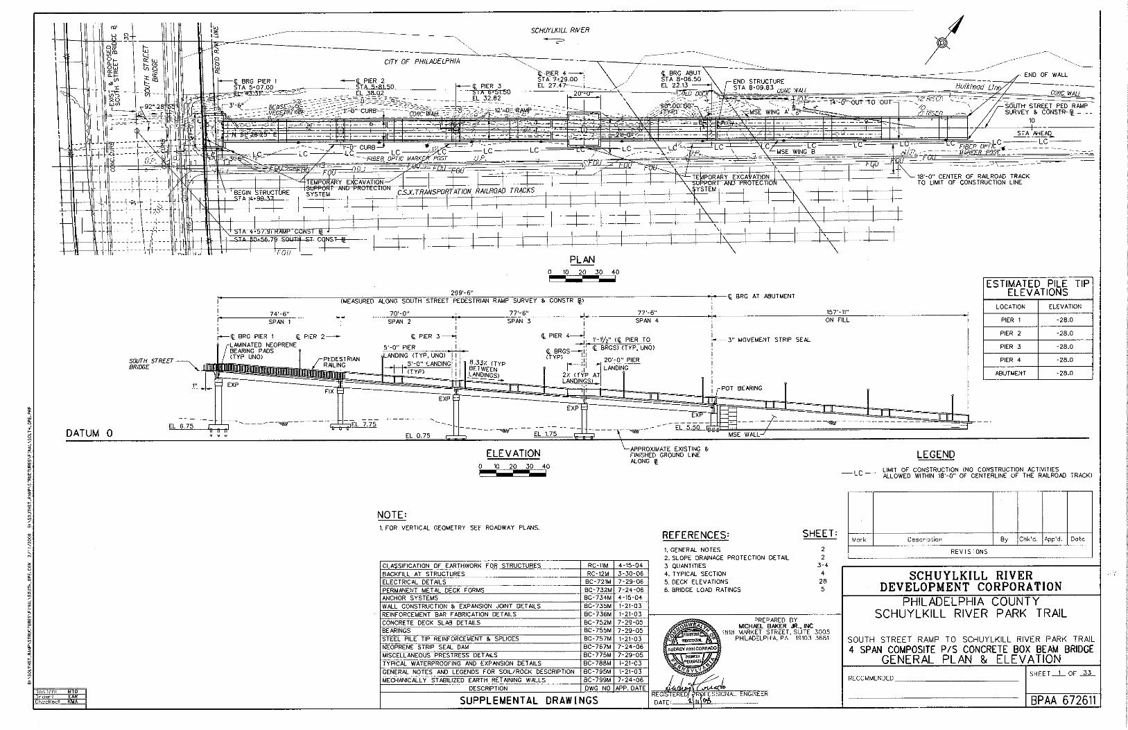
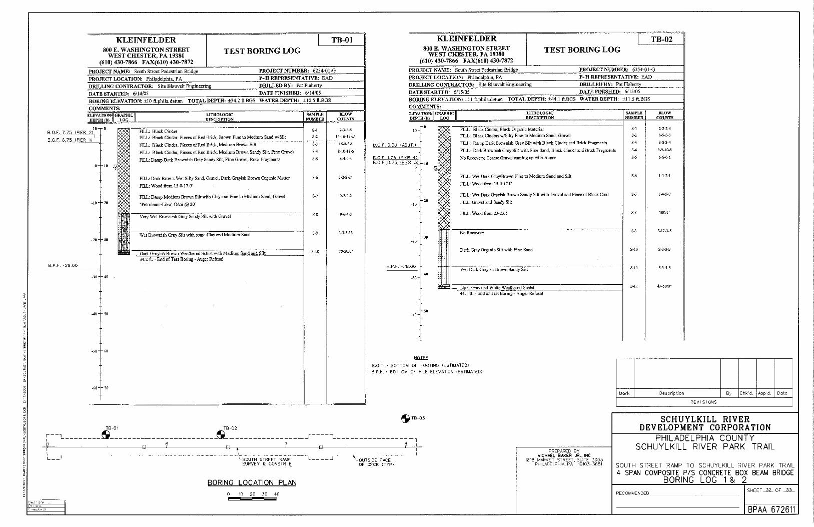
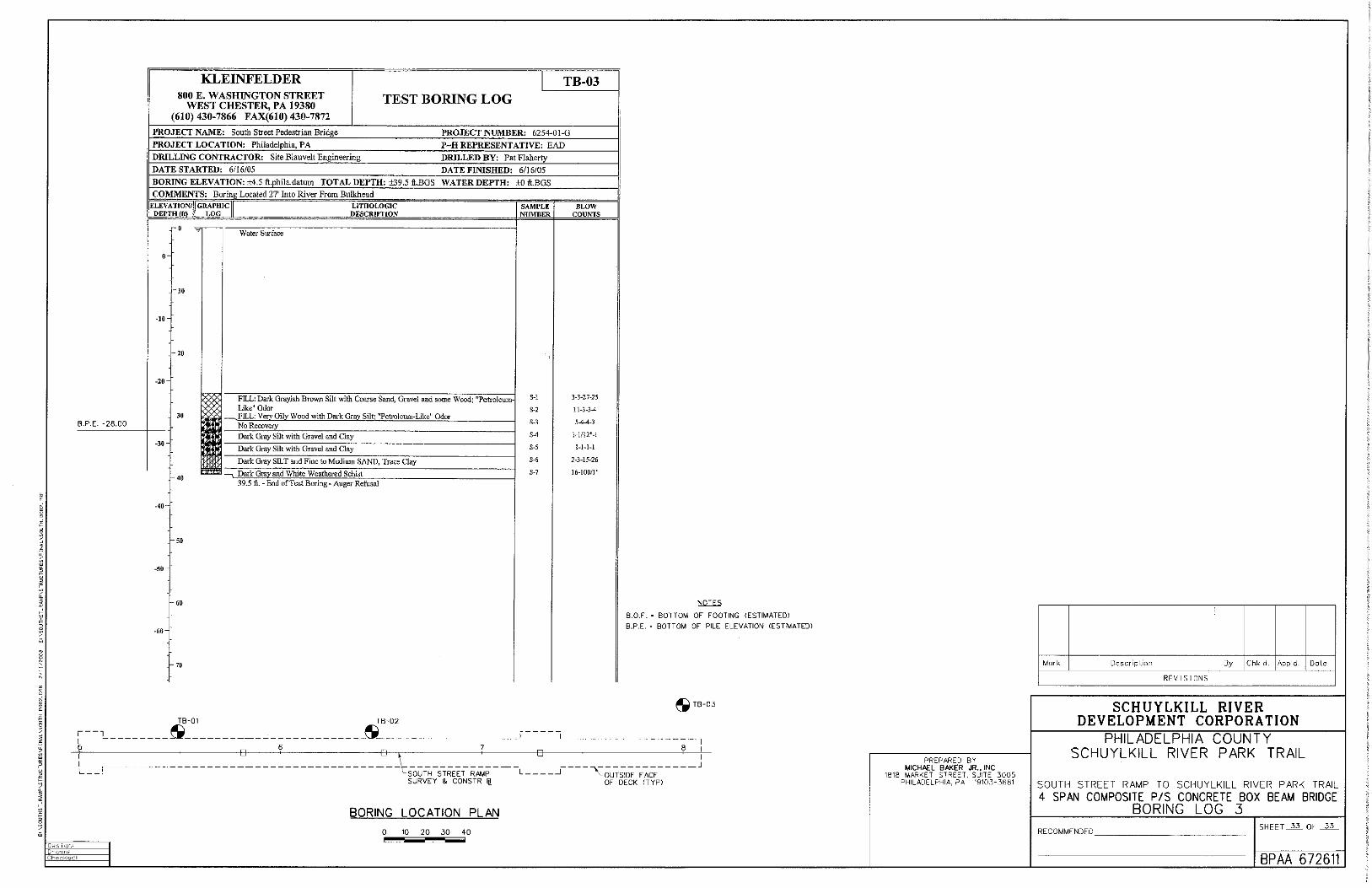

APPENDIX K
QA FORM
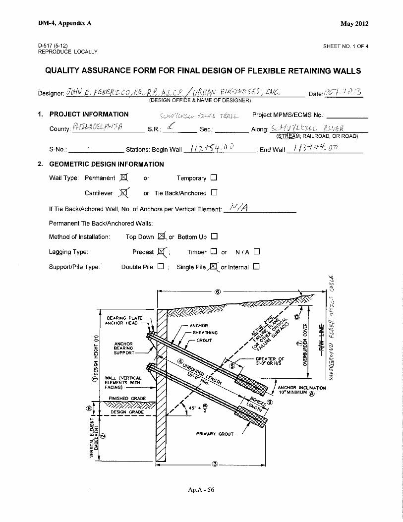
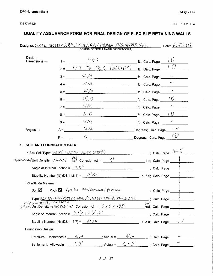

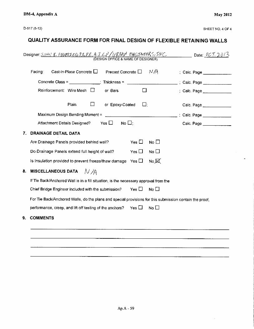
APPENDIX L
SPECIAL PROVISION
1
SPECIAL PROVISION
FOR
DESIGN-BUILD RETAINING WALL
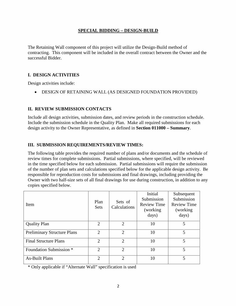
2
SPECIAL BIDDING – DESIGN-BUILD
The Retaining Wall component of this project will utilize the Design-Build method of contracting. This component will be included in the overall contract between the Owner and the successful Bidder.
I. DESIGN ACTIVITIES
Design activities include:
• DESIGN OF RETAINING WALL (AS DESIGNED FOUNDATION PROVIDED)
II. REVIEW SUBMISSION CONTACTS
Include all design activities, submission dates, and review periods in the construction schedule. Include the submission schedule in the Quality Plan. Make all required submissions for each design activity to the Owner Representative, as defined in Section 011000 – Summary.
III. SUBMISSION REQUIREMENTS/REVIEW TIMES:
The following table provides the required number of plans and/or documents and the schedule of review times for complete submissions. Partial submissions, where specified, will be reviewed in the time specified below for each submission. Partial submissions will require the submission of the number of plan sets and calculations specified below for the applicable design activity. Be responsible for reproduction costs for submissions and final drawings, including providing the Owner with two half-size sets of all final drawings for use during construction, in addition to any copies specified below.
Item Plan Sets
Sets of Calculations
Initial Submission
Review Time (working
days)
Subsequent Submission
Review Time (working
days)
Quality Plan 2 2 10 5
Preliminary Structure Plans 2 2 10 5
Final Structure Plans 2 2 10 5
Foundation Submission * 2 2 10 5
As-Built Plans 2 2 10 5
* Only applicable if “Alternate Wall” specification is used
3
Review times begin and end when a submission is logged in and out, respectively, by all designated reviewers. The login time will be taken as the latest date in which the submission is received by the reviewers. Submittals received after 11:00 a.m. will be logged in as the next working day following receipt of the submission. For electronic submissions, the login time will be taken when the appropriate reviewer and Owner Representative receive an email stating a submission is ready for review. Logout time occurs when the reviewer sends an email to the Contractor with an approval and/or comments. If a submission is incomplete or otherwise requires additional information or data to complete the review properly, the review time will begin as specified for the submission when all required information is received.
Additional contract time or price adjustment to any contract items will not be considered due to failure to obtain approvals within the specified review times resulting from incomplete or non-conforming submissions. Working days are weekdays, Monday through Friday, excluding official holidays. Include all review periods identified above as activities in the project schedule.
IV. GENERAL DESIGN REQUIREMENTS
Have the design completed by a Professional Engineer licensed in the State. Have all surveys completed by a Professional Land Surveyor licensed in the State. Provide all Professional Engineer’s seals in accordance with Pa. Code § 37.59.
Provide the Design Engineer's P.E. seal, the date signed, and business name and address on the first sheet of all computations, including computations for partial submissions. Provide the appropriate seal and signature on plan sheets in accordance with the Pennsylvania Department of Transportation's Design Manuals. Also, provide the Design Engineer's P.E. seal, signature, and date signed on the first sheet of all computations, including computations for partial plans submissions.
Designs copied directly from Pennsylvania Department of Transportation Standard Drawings need not be documented through independent computations. List such designs on the submission by referencing the drawing number of the applicable standard, and the sheet number, table, or graph.
Experimental or demonstration-type design concepts, products, structures, or elements not pre-approved by the Owner for general usage at the time of bid, will not be allowed. Designs that take advantage of any errors and/or omissions in the following requirements will not be accepted. In the event any such error, omission, or discrepancy is discovered, immediately notify the Owner. Failure to notify the Owner will constitute a waiver of all claims for misunderstanding, ambiguities, or other situations resulting from the error, omission, or discrepancy.
Final Plans must include a note on all tabulation of quantities sheets included therein that states “Item numbers and descriptions listed in Tabulations are solely for the purposes of identifying the specified units of work and locations, and are not to be construed as contract or pay items.”
4
Design and construct any support of excavation required by any Design Activities identified in Section I of this Special Provision in accordance with the Special Provision titled TEMPORARY EXCAVATION SUPPORT AND PROTECTION SYSTEM FOR DESIGN-BUILD PROJECTS.
During construction, Contractor’s engineer shall be responsible for reviewing and approving shop drawings. A copy of each shop drawing must also be submitted to Owner.
Design Specifications
Perform the design activities identified in Section I, Design Activities, in accordance with the latest published edition of all Pennsylvania Department of Transportation Standards, Specifications, Regulations, Strike-off Letters, and other industry standards, at the time of advertisement, unless directed otherwise, or as identified in the bid package. These include, but are not limited to the following:
• Special Provisions;
• Publication 408, Specifications
• Publication 72M, Standards for Roadway Construction
• Publication 218M, Standard Drawings for Bridge Design
• Publication 219M, Standard Drawings for Bridge Construction
• Publication 10 Design Manual Part 1 – Transportation Program Development and Project Delivery Process
• Publication 10A Design Manual Part 1A – Pre-TIP and TIP Program Development Procedures
• Publication 10B Design Manual Part 1B – Post-TIP NEPA Procedures
• Publication 10C Design Manual Part 1C – Transportation Engineering Procedures
• Publication 10X Design Manual Part 1X – Appendices to Design Manuals 1, 1A, 1B, and 1C
• Publication 13M Design Manual Part 2 – Highway Design
• Publication 14M Design Manual Part 3 – Plans Presentation
• Publication 15M Design Manual Part 4 – Structures
• Publication 16M Design Manual Part 5 – Utility Relocation
• Publication 584, Drainage Manual
• Publication 46, Traffic Engineering Manual
• Publication 149, Traffic Signal Design Handbook
5
• Publication 35, Approved Construction Materials
• Publication 203, Work Zone Traffic Control
• Publication 213, Temporary Traffic Control Guidelines
• Publication 222, Subsurface Boring, Sampling, and Testing Contract
• Publication 293, Geotechnical Engineering Manual
• Publication 378, Right-of-Way Manual
• Pa Code Title 67, Chapter 204, Guidelines to Implement Act 229 of 2002, Additional Traffic Control Devices in Highway Work Zones, Statement of Policy
• Pa Code Title 67, Chapter 212, Official Traffic Control Devices (Publication 212)
• Publication 236M, Handbook of Approved Signs
• Publication 242, Pavement Policy Manual
• Publication 281, Waste Site Evaluation Procedures for Highway Project Development Process;
• Publication 371, Grade Crossing Manual
• Publication 122M, Surveying and Mapping Manual
• Publication 111M, Traffic Control – Pavement Markings and Signing Standards
• Publication 148, Traffic Standards – Signals
• Publication 611, Waste Management Guidance Manual
• Publication 7, Items Catalog
• Manual on Uniform Traffic Control Devices (FHWA)
• A Policy on Geometric Design of Highway and Streets, AASHTO "Green Book"
• A Policy on Design Standards – Interstate System (AASHTO)
• AASHTO Guide Specifications for Horizontally Curved Highway Bridges
• AASHTO LRFD Bridge Design Specifications or, when applicable, AASHTO Standard Specifications for Highway Bridges
The design should be performed using the most conservative design criteria from the sources listed above. In the event that a clear order of predominance cannot be established, or a difference in interpretation of the design cannot be resolved, the Owner Representative will be the arbiter and his/her decision will be final. For bridge/structures related design activities, refer to the "Bridge/Structures Related Effective Policy Letters" for additional design policy Strike-Off Letters that are applicable to the structure design.
6
In the event that certain design parameters, stresses, or specifications are in conflict regarding bridge/structures related design activities, the following order of predominance governs:
• Design requirements listed herein and addenda (addendum) to the proposal.
• Design related Strike-Off Letters in effect on the date of project advertisement.
• Publication 15M Design Manual Part 4, Structures
• Publications 218M and 219M Standard Drawings for Bridge Design and Bridge Construction
• AASHTO LRFD Bridge Design Specifications or, when applicable, AASHTO Standard Specifications for Highway Bridges
The design should be performed using the most conservative design criteria from the sources listed above. In the foregoing instances, in the event that a clear order of precedence cannot be established, or a difference in the interpretation of the design criteria, standards, specifications, or methodology cannot be resolved, the Owner Representative will be the arbiter and whose decision will be final.
V. SCHEDULE OF VALUES
Where indicated, partial payment for lump sum design-build items will be made on Current Estimate Payments based on the amount of work completed during the estimate period based on a payout schedule (Schedule of Values). The Owner will base amount of the partial payments on the total value of the work performed to the date of the estimate cut-off, less payments previously made, in accordance with the approved Schedule of Values.
Prepare a Schedule of Values for each lump sum Item associated with the design or construction of the Design Activities identified in Section I of this Special Provision, where the Special Provision for that "Design" or "Construct" Item indicates lump sum measurement and payment by Schedule of Values, using the attached Schedule of Values template as a guide. Hereinafter, Design Items are defined as the Contract Item associated with the Design Activities identified in Section I, and Construct Items are defined as the Contract Item associated with the construction of the Design Activities identified in Section I. Distribution of payments among Schedule of Values Components must bear a reasonable resemblance to the actual value of work.
(a)For Design items, if a Component is not applicable, indicate 0%; otherwise do not indicate values less than 5% in any Component. Include those Schedule of Values Components identified in the associated Design Item Special Provisions. Payment for Design Item Schedule of Values Components will be made in the amount of the approved percentage upon completion of the identified task. When Schedule of Values Components are identified in the Special Provisions with “Approval” in the Schedule of Values Component title, 75% of the approved percentage may be paid on the next estimate following login of that submission, and the remaining 25% of the approved percentage will be paid following approval of that submission. Otherwise, no partial payment will be made for Design Item Components.
7
(b)For Construct Item, include Schedule of Values Components relevant to the scope of work of the particular item, using the attached Schedule of Values template as a general guide. No partial payment will be made for Construct Item Schedule of Values Components. Accordingly, develop the Schedule of Values to include Schedule of Values Components in sufficient numbers and detail to be payable upon semi-monthly estimates throughout the duration of the Contract.
Submit the Schedules of Values to the Owner for review and approval. No estimate will be processed until all Schedules of Values are approved.
VI. CONSTRUCTION CONTACT
The Owner’s contact for Current Estimate Payments as defined in Section 110.05 will be:
• The Project Manager identified in Section II of this Special Provision.
8
DESIGN OF RETAINING WALL
(AS DESIGNED FOUNDATION PROVIDED)
DESCRIPTION
This work is the design and preparation of construction plans for a retaining wall of the type indicated on the Owner's Conceptual Structure Plans or an alternate type retaining wall. Preparation of a Preliminary Structure Submission for the proposed retaining wall type is also required.
DESIGN
(a) General
The Owner's Conceptual Structure Plans represent a retaining wall type and layout that will meet safety, hydraulic, geometric, environmental, and load carrying capacity requirements for the project. A retaining wall type and configuration as that shown on the Conceptual Structure Plans or an alternate type retaining wall subject to the requirements specified herein may be designed and constructed. Prepare and submit a Preliminary Structure submission for the proposed retaining wall for review and approval.
Foundation type(s) along with geotechnical design parameters are provided for the retaining wall foundation. Use the foundation type(s) and design parameters (hereinafter referred to as "as-designed") to design the retaining wall or develop an alternate foundation type and design parameters subject to the limitations specified. Provide design and drawings in the units of measurement shown on the Conceptual Structure Plans.
Provide a complete set of computations for the retaining wall, excluding piles and drilled caissons. If an alternate foundation is proposed, also provide a complete set of computations for the proposed foundation type. Provide additional calculations, as requested by the Owner's Representative, to evaluate any details throughout the life of the contract.
Design wall for the models provided in Appendix M of the Preliminary Geotechnical Summary Report. No live load surcharge is required for design of the wall.
Structure types, concepts, construction sequencing, or other details that are not covered in the design and construction specifications or standards, or practice not commonly used in Pennsylvania are allowed only when specifically indicated herein. Where design or construction
9
that deviates from standard Pennsylvania Department of Transportation practice is proposed, submit a conceptual design before the Preliminary Structure Plans for review and approval. Include in the submittal conceptual plans, and a list of items that deviate from standard design and construction, including but not limited to design methodology, the computer program that will be used in the design, construction sequencing, and any specialized construction techniques. No extensions of contract time will be granted for pursuits of alternates or non-standard designs.
(b) Additional Designer Qualifications
None.
(c) Additional Information/Data Made Available to the Contractor by the Owner
The following information/data will be made available to the Contractor during the advertisement period: (List the following, as applicable)
• Test Boring Core Boxes: Test boring core boxes are available for inspection. Contact Lane Fike at 215-222-6030 to arrange for a date and time to inspect the core boxes.
(d) Design Specifications
Develop the Preliminary Structure Plans and prepare the structure construction plan in accordance with the Special Provision titled SPECIAL BIDDING – DESIGN-BUILD, Section IV – General Design Requirements, Design Specifications.
(e) Design Requirements
1. General
• Slip-formed barriers are not allowed. • Lightweight concrete is not allowed. • MSE walls are not allowed. • Precast modular wall are not allowed. • Precast barriers are not allowed. • Barrier type differing from that shown on the Conceptual Structure Plan is not
allowed. • Post and Panel type walls are allowed. • Permanent anchored walls are not allowed.
10
o Driven piles are not permitted for use with precast concrete wall panels.
• Cast-In-Place concrete wall panels are allowed. • Shotcrete wall panels or facing is not allowed. • Timber lagging wall panels are not allowed. • The base of the wall or wall panel must extend 6 feet minimum below the
proposed ground line. • Secant walls are not allowed. • Reinforced Soil Slopes are not allowed. • Soil Nail Walls are not allowed. • Design for the presence of water behind the wall as shown on design models. • Limit the allowable lateral deflection at the top of caissons to ½ inch for
service condition • Cast-in-place reinforced concrete walls supported on piles are allowed. • Provide galvanized steel piles. • Excavate according to OSHA or other applicable local, state, and federal
regulations. Provide temporary shoring of excavated areas as necessary. It is the contractor’s responsibility to ensure stability of the excavation.
2. Geometry
Design the structure according to the geometrics shown on the Conceptual Structure Plans, except changes will be allowed as follows:
• Horizontal Alignment: No Change Allowed. • Vertical Alignment: No Change Allowed. • Wall Length: No Change Allowed.
3. Seismic
Site Class is not Class E.
4. Maintenance of Traffic During Construction
Not Applicable.
5. Railroad Requirements
Design the wall to meet the following railroad requirements:
11
• Minimum Horizontal Clearance: CSX Railroad right-of-way line is located approximately 27 feet behind the front face of the proposed wall.
• Temporary Support for Railroad Tracks: Not Applicable.
6. Inspection and Maintenance Accessibility
Provide inspection and maintenance accessibility equivalent to that provided in the Conceptual Structure Plans, or alternate means acceptable to the Owner. In case of a disagreement on accessibility, the Owner Representative's decision will be binding.
7. On-Wall Lighting
None.
8. Waterway Requirements
None.
8.a. Structure Shown on the Conceptual Structure Plan:
See attached plans for Conceptual Structure Plan.
9. Environmental
Refer to Section 026113 – Excavation of Contaminated Materials Handling.
10. Utilities
Design the retaining wall to accommodate the existing utility facilities at the retaining wall.
Underground fiber optics cable is located approximately 19 feet behind the front face of the proposed retaining wall. Do not excavate any soils within 5 feet of the underground fiber optics cable. If necessary, utilize temporary excavation support system to avoid any disturbance to the underground fiber optics cable.
12
If utility relocations are required as part of an alternate structure, be responsible for securing approvals from the affected utility companies.
11. Other
None.
(f) Foundations
1. General - Design the retaining wall using as-designed geotechnical design parameters and requirements or an alternate foundation type as allowed herein.
• The construction, including any temporary construction, is to be performed in accordance with PennDOT Publication 408. The Contractor is responsible for the stability of all excavated slopes. Perform all excavation in accordance with OSHA requirements.
• Recommended wall type for the proposed retaining wall is a soldier pile and lagging wall. Allowable alternate wall type is a cast-in-place reinforced concrete wall supported on piles.
• Design retaining wall so that none of the wall elements will encroach within 5.0 feet of existing underground fiber optic cable and do not extend into CSX Railroad right-of-way.
• Utilize frost depth of 3.0 feet in design.
• Consider extreme event condition (i.e., rapid draw down) in design.
• Backfill behind the retaining wall in accordance with PennDOT Standard RC-12M. Structure backfill may consist of material meeting AASHTO No. 57 or PennDOT Open Graded Subbase (OGS) criterion.
• Temporary shoring and/or stream diversion barriers along with dewatering techniques may be required for construction of substructure units.
• Treat project location as potentially corrosive environment and corrosion protection measures are required.
13
• All excavated material shall be handled based on Section 026113 – Excavation of Contaminated Materials Handling.
• Provide riprap rock scour protection as per DM-4, Section PP.7.2.5 and as shown on the plans. Bottom of riprap shall extend to bottom of lagging elevation.
2. As-Designed Foundation - Use the following in conjunction with the foundation type(s) shown on the Conceptual Structure Plans:
2.a. Geotechnical Design Parameters
2.a.1. Spread Footings on Soil: Not Applicable.
2.a.2. Spread Footing on Rock: Not Applicable.
2.a.3. Pile Supported Footings: Not Applicable.
2.a.4. Drilled Caisson Supported Footings:
Bottom of Footing Elevation: Refer to the Conceptual Structure Plans
Estimated Length of Shaft in Soil: Refer to the Conceptual Structure Plans
Estimated Length of Shaft in Rock: Refer to the Conceptual Structure Plans
Estimated Length of Rock Socket: Refer to the Conceptual Structure Plans
Extend caissons a minimum of 5.0 feet into bedrock.
The caisson diameter is 2.5 feet with center-to-center spacing of 8.0 feet.
Utilize galvanized steel piles.
Design wall utilizing the models provided in Appendix M of the Preliminary Geotechnical Summary Report
2.a.5. Permanent Anchored Walls: Not Applicable.
2.b. Foundation Design Information
• The soldier pile wall must be designed in accordance with all requirements listed in the AASHTO 2010 LRFD Bridge Design Specifications and PennDOT Design Manual -4, 2012, including all revisions.
• Temporary casing may be required to maintain an open borehole. If temporary casing is utilized, maintain concrete levels above the bottom of casing at all times during extraction to prevent caved material from contaminating the concrete.
14
• Backfill caisson borehole within 24 hours after drilling to limit the deterioration of the bearing material.
• The minimum required pile size is W12 x 190.
• The caisson diameter is 2.5 feet.
• Place bottom of lagging at elevation -3.0 feet.
• Extend caissons a minimum of 5.0 feet into bedrock.
• If subsurface condition encountered during construction varies from what was encountered during subsurface exploration program, perform global stability analysis of the retaining wall as directed by the Engineer.
• Design soldier pile and lagging wall with the following parameters.
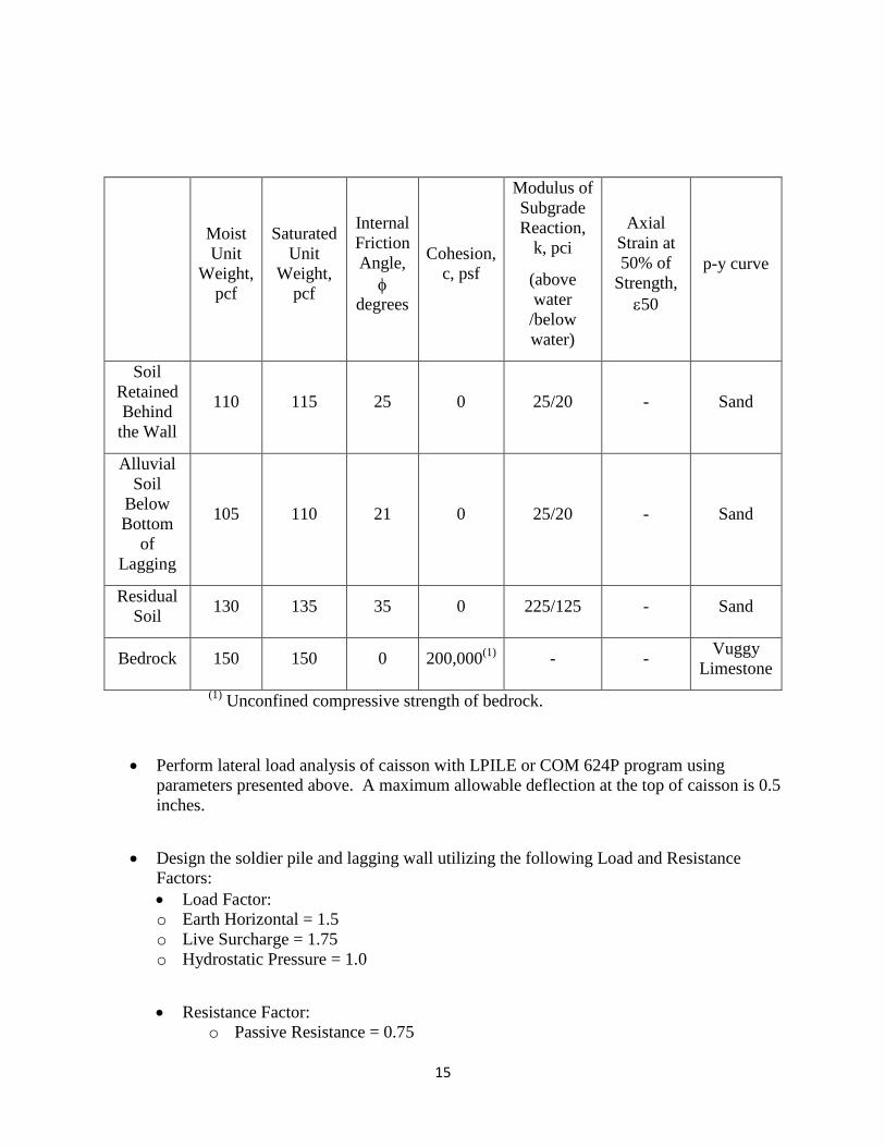
15
(1) Unconfined compressive strength of bedrock.
• Perform lateral load analysis of caisson with LPILE or COM 624P program using parameters presented above. A maximum allowable deflection at the top of caisson is 0.5 inches.
• Design the soldier pile and lagging wall utilizing the following Load and Resistance Factors: • Load Factor: o Earth Horizontal = 1.5 o Live Surcharge = 1.75 o Hydrostatic Pressure = 1.0
• Resistance Factor: o Passive Resistance = 0.75
Moist Unit
Weight, pcf
Saturated Unit
Weight, pcf
Internal Friction Angle, φ
degrees
Cohesion, c, psf
Modulus of Subgrade Reaction,
k, pci
(above water /below water)
Axial Strain at 50% of
Strength, ε50
p-y curve
Soil Retained Behind
the Wall
110 115 25 0 25/20 - Sand
Alluvial Soil
Below Bottom
of Lagging
105 110 21 0 25/20 - Sand
Residual Soil 130 135 35 0 225/125 - Sand
Bedrock 150 150 0 200,000(1) - - Vuggy Limestone
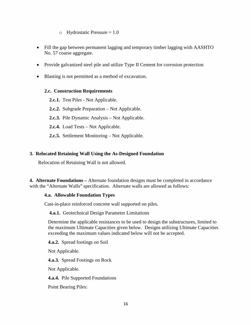
16
o Hydrostatic Pressure = 1.0
• Fill the gap between permanent lagging and temporary timber lagging with AASHTO No. 57 coarse aggregate.
• Provide galvanized steel pile and utilize Type II Cement for corrosion protection • Blasting is not permitted as a method of excavation.
2.c. Construction Requirements
2.c.1. Test Piles - Not Applicable.
2.c.2. Subgrade Preparation – Not Applicable.
2.c.3. Pile Dynamic Analysis – Not Applicable.
2.c.4. Load Tests – Not Applicable.
2.c.5. Settlement Monitoring – Not Applicable.
3. Relocated Retaining Wall Using the As-Designed Foundation
Relocation of Retaining Wall is not allowed.
4. Alternate Foundations – Alternate foundation designs must be completed in accordance with the “Alternate Walls” specification. Alternate walls are allowed as follows:
4.a. Allowable Foundation Types
Cast-in-place reinforced concrete wall supported on piles.
4.a.1. Geotechnical Design Parameter Limitations
Determine the applicable resistances to be used to design the substructures, limited to the maximum Ultimate Capacities given below. Designs utilizing Ultimate Capacities exceeding the maximum values indicated below will not be accepted.
4.a.2. Spread footings on Soil
Not Applicable.
4.a.3. Spread Footings on Rock
Not Applicable.
4.a.4. Pile Supported Foundations
Point Bearing Piles:

17
Ultimate pile capacity is limited to a maximum yield strength of 50 ksi.
Utilize 1/16 inch reduction in the pile section for design.
End Bearing Piles:
Ultimate pile capacity is limited a maximum yield strength of 50 ksi.
Utilize 1/16 inch reduction in the pile section for design.
• Support cast-in-place reinforced concrete wall on piles.
• A minimum pile length of 10.0 feet is required.
• Use a resistance factor of 0.35 to determine the axial structural pile resistance at the strength limit state.
• Use a resistance factor of 0.25 to determine the axial structural pile resistance at the service limit state.
• Drive piles to Case 2 Absolute End Bearing Refusal in bedrock in accordance with Pub. 408/2011, Section 1005.3(b)4. Use driving method A as per DM-4, Part A, Section 1.7.5.
• Design cast-in-place reinforced wall with following parameters.
Moist Unit
Weight, pcf
Saturated Unit
Weight, pcf
Internal Friction Angle, φ degrees
Cohesion, c, psf
Modulus of Subgrade
Reaction, k, pci
(above water /below water)
Axial Strain at 50% of
Strength, ε50
p-y curve
Soil Retained
Behind the Wall
110 115 25 0 25/20 - Sand
Alluvial Soil Below Bottom of Lagging
105 110 21 0 25/20 - Sand
18
(1) Unconfined compressive strength of bedrock.
• Utilize 1/16” reduction in the pile section for design.
• Backfill behind the proposed wall in accordance with PennDOT Standard RC-12M.
Friction Piles:
Not Applicable.
4.a.5. Drilled Caisson Supported Foundations
Not Applicable.
4.b. Required Geotechnical Exploration
None.
4.c. Foundation Submission
Prepare and submit a foundation report according to the requirements of Publication 15M, Design Manual Part 4 (DM 4), Policies and Procedures (PP), Section 1.9.4. Cost comparisons per Section 1.9.4.3(c) are not required.
4.d. Construction Requirements
4.d.1. Test Piles
Not Applicable.
4.d.2. Subgrade Preparation
Not Applicable.
4.d.3. Pile Dynamic Analysis
Not Applicable.
4.d.4. Load Tests
Not Applicable.
4.d.5. Settlement Monitoring
Not Applicable.
4.d.6. Other
Residual Soil 130 135 35 0 225/125 - Sand
Bedrock 150 150 0 200,000(1) - - Vuggy Limestone
19
Not Applicable.
(g) Submittals
1. Preliminary Structure Submission
Include the following information in the Preliminary Structure submission:
1. Preliminary Structure submission letter: In accordance with DM 4, PP Section 1.9.3.3.1(a).
2. Preliminary Structure plans: In accordance with DM 4, PP Section 1.9.3.3.1(b).
3. Supply the following additional information:
(a) Name of Lead Design Engineer
2. Foundation Submission
Not applicable for as-designed foundation.
3. Final Structure Plans and Computations
In accordance with applicable sections of DM 4. Include in the Final Structure Plans the Core Boring Logs as provided in the Conceptual Drawings in unmodified form; with the exception of superimposition of sheet numbering consistent with the Final Structure Plans and prominent designation of each sheet as "Information Provided by Others." Sign and seal each plan sheet per DM 4, Section PP 1.6.3.1, with the exception of the aforementioned Core Boring Logs. Upon completion of Quality Assurance Review, or Owner’s Perspective Review, as applicable, and receipt of drawings stamped “Recommended for Construction,” provide the Owner with one paper copy for signature by the Owner Representative.
4. Revisions During Construction, As-Built Drawings, and Shop Drawings
In accordance with DM 4, PP Section 1.10, except that the Lead Design Engineer is responsible for making changes to the contract drawings, and making and distributing necessary copies of the revised plans to all affected parties. PP Section 1.10.5 is modified as follows: If a design error occurs, the Contractor is fully responsible for the costs associated with providing additional design analysis and construction modifications, acceptable to the Owner, to correct the problem. The Owner will require reimbursement for design errors to cover engineering review costs. This amount shall be deducted from the lump sum cost for the construction of structure item via work order.
Maintain and submit As-Built Drawings in accordance with Publication 10C, Design Manual Part 1C, Transportation Engineering Procedures, Section 5.7, As-Built Plans, except include major quantity changes (such as foundation pile length changes, etc).
20
All as-built drawings are the sole responsibility of the Contractor and must be submitted to the Owner within 3 months of final inspection acceptance as defined in Section 110.08(a).
During construction, Contractor’s engineer shall be responsible for reviewing and approving shop drawings. A copy of each shop drawing must also be submitted to the Owner.
(h) Submittal Review, Approval, and Distribution
Make all submissions in accordance with the Special Provision titled SPECIAL BIDDING – DESIGN-BUILD, except as follows;
• Partial Plans Submissions: None. • Utilities: Additional contract time will not be considered for additional utility
relocation work associated with an alternate structure.
MEASUREMENT AND PAYMENT – Lump Sum
Partial payment will be made for the design activity based on the approved Schedule of Values in accordance with Section V of Special Provision titled SPECIAL BIDDING – DESIGN-BUILD, utilizing the following components:
• Preliminary Plan Approval • Final Plan Approval • Final Plan – for Signature • As-Built Drawings
21
ALTERNATE WALLS
DESCRIPTION
This work is for construction of retaining walls as-designed or designing and constructing equivalent retaining walls of an alternate design in place of the “as-designed” retaining walls.
DESIGN
(a) General. If alternate design retaining walls are bid, furnish, to the Owner, preliminary conceptual design calculations and drawings for the alternate retaining walls. Provide an alternate design equivalent to the original design and meeting applicable design criteria for strength and serviceability. Submit the alternate design to the Owner for acceptance. Refer to PennDOT Design Manual Part 4, PP 1.10, Bridge Submissions-Construction Phase, for details on procedures for contractor submissions. If the equivalency of an alternate design cannot be clearly established, the Owner Representative will be arbiter and the Owner Representative’s decision will be final. Furnish, with the preliminary conceptual design submission, a tabulation identifying the differences between the “as designed” retaining walls and the alternate design retaining walls.
On the alternate design plans include the type of wall, location, length, top elevation(s), proposed bottom of footing/leveling pad elevation(s), cross-sections including backfill material type and limits, and quantities. Also show, as required, details for concrete bridge barriers and/or railings, copings, conduit, or other attachments to precast wall panels/units. Show complete layout plans and fabrication details for precast wall panels/units and footings/leveling pads including reinforcement and attachments, and step-by-step erection instructions. Include details for strip or wire mesh reinforcement and attachments, for anchoring panels into the soil. Any fabrication done before acceptance of the plans will be at the Contractor’s risk.
Any delay in submission and acceptance of a proposed alternate design or a revision, and/or approval of required permits, will not extend the contract time.
If alternate design retaining walls is bid, and an acceptable preliminary conceptual design is not approved within 30 calendar days from the award date (6 days for the submission and 24 days for Owner review), construct the “as-designed” retaining walls at no additional cost to the Owner.
22
Alternate designs which take advantage of any errors and/or omissions in the plans for the “as-designed” wall or discrepancies between the “as-designed” wall plans and the special provisions covering alternate designs, will not be accepted. In the event any such error, omission, or discrepancy is discovered, immediately notify the Owner. Failure to notify the Owner will constitute a waiver of all claims for misunderstandings, ambiguities, or other situations resulting from the error, omission, or discrepancy.
Experimental or demonstration-type design concepts; or products, structures, or elements not preapproved by the Owner for general usage, will not be allowed in the alternate design.
Value Engineering may be applied to the “as-designed” retaining walls, but do not Value Engineer alternate design retaining walls.
Have the alternate design completed by a Professional Engineer registered in the Commonwealth of Pennsylvania. All engineering firms must have a current Annual Qualification Package on file with the Bureau of Project Delivery’s Consultant Management Section and be registered business partners in ECMS.
Submit an affidavit, before or along with the preliminary conceptual design submission, stating that the designer is familiar with AASHTO, PennDOT, and other applicable design criteria, standards, and construction specifications. Also, submit a list of similar retaining walls and/or wingwalls/bridges designed within the past 7 years.
In identifying alternate design retaining walls, retain the “as designed” retaining wall number, but suffix the number with the letters A, B, etc. Proprietary walls shall have a P suffix as detailed in Design Manual Part 4 PP3.3.4.7(k).
Show, on first sheet of the alternate design, the seal of a Professional Engineer registered in the Commonwealth of Pennsylvania, a valid signature in ink, the date signed, a business name, a business address, and the note “These drawings (S-XXXXXA) supersede drawings (S-XXXXX) approved (insert appropriate date)”. Also include a statement “All assumptions made in the design are validated either by details or notes on these drawings.”
The Owner will furnish CADD files for the “as-designed” retaining walls upon request.
Prepare alternate design plans using Pennsylvania Department of Transportation drafting standards.
23
(b) Design Computations and Design Specifications. On the first sheet of the computations for the alternate design, show the seal of a Professional Engineer registered in the Commonwealth of Pennsylvania, a valid signature in ink, and the date signed.
Provide a complete set of computations for the alternate design of the retaining walls. Reproduce and insert computations from the “as-designed” walls, as needed. Provide additional calculations, as requested by the Owner Representative to justify the design, throughout the life of the contract.
Designs copied directly from approved Pennsylvania Department of Transportation Standards need not be documented through independent computations. List such designs on the submission by referencing the drawing number of the applicable standard, and the sheet number, table, or graph.
Use PennDOT Design Manual Part 4 for design policy procedures and criteria. All design related Strike-off Letters listed in PART B, “SPECIAL DRAWINGS AND SPECIAL DESIGN REQUIREMENTS”, are applicable to the alternate design.
In the event that certain design parameters, stresses, or specifications are in conflict, the following order of predominance governs:
• Design requirements listed herein, in PART B, “SPECIAL DRAWINGS AND SPECIAL DESIGN REQUIREMENTS” and addenda (addendum) to the proposal.
• Design related Strike-off Letters in effect on the date of project advertisement. • PennDOT Design Manual Part 4, “Structures” including revisions (Publication 15M). • PennDOT Bridge Design and Bridge Construction Standards (Publications 218M and
219M). • AASHTO LRFD Bridge Design Specifications as indicated for the “as-designed” walls.
In the event that a clear order of predominance cannot be established, or a difference in the interpretation of the design criteria, standards, specifications, or methodology cannot be resolved, the Owner Representative will be arbiter and the Owner Representative’s decision will be final.
Submit shop drawings to the Owner as specified in Section 105.02 for review and acceptance. The Owner is not responsible for work done without approved shop drawings.
24
If any provisions in PART B conflict with those in PART A, the provisions in PART B are to govern.
Within 60 calendar days after completion of the walls, revise the original drawings to show “as-built” conditions and submit them to the Owner Representative.
(c) Design Requirements. In the design of alternate retaining walls, comply with PennDOT Design Manual Part 4, “Structures”, Section 11, and other design criteria as specified for the “as-designed” retaining walls, subject to the exceptions and/or additions in PART B, “SPECIAL DRAWINGS AND SPECIAL DESIGN REQUIREMENTS”.
Provide equivalent inspection and maintenance accessibility for the alternate retaining wall as for the “as-designed” retaining wall. In case of a disagreement on accessibility, the Owner Representative’s decision will be final.
Do not change the indicated horizontal and vertical alignment of retaining walls, except as noted in PART B, “SPECIAL DRAWINGS AND SPECIAL DESIGN REQUIREMENTS”.
Design alternate retaining walls to be within the indicated limits of factored foundation bearing resistance and factored pile resistance as indicated for the “as designed” walls.
Provide clear span(s) and/or distances from wall faces of not less than the minimum values indicated for the “as-designed” retaining walls, except as noted in PART B, “SPECIAL DRAWINGS AND SPECIAL DESIGN REQUIREMENTS”.
Comply with all requirements of the approved permit(s). Obtain approved/amended waterway permit(s) for alternate structures if necessary.
Be responsible for the cost and delay of any additional utility relocation that results from changes in the Contractor’s plans or construction sequences made subsequent to (1) acceptance of the utility’s relocation plans and (2) where the utility has physically moved its facilities based upon those relocation plans.
MATERIALS
As indicated and as specified for each respective item included in the “as-designed” retaining walls.
25
CONSTRUCTION
In accordance with Publication 408, Special Provisions for each respective item, and any additional requirements specified herein. Submit construction procedures for an alternate design for acceptance, if other than those specified herein.
If utility relocations are required as part of an alternate design, be responsible for the cost of the utility relocations and any related delay claim costs.
MEASUREMENT AND PAYMENT – Lump Sum
For the type of alternate design wall selected; subject to a reduction equal to the amount of the Contractor’s share of the Owner’s engineering costs as follows:
• For each alternate wall $100,000 or less .........................................................$1,000 • For each alternate wall over $100,000 but less than $500,000 .......................$2,000 • For each alternate wall over $500,000 but less than $1,000,000 ....................$3,500 • For each alternate wall $1,000,000 or more ...................................................$5,000
The Contractor’s share of the Owner’s engineering costs will be recovered by processing a contract adjustment (Alternate Design Review) to reduce the contract lump sum price by an amount equal to the Contractor’s share.
A utility company’s share of fabricated structural steel and/or installation of sleeves, inserts, casings, hanger assemblies, ducts, etc. for utilities is to be a separate item. Do not include the utility company’s share in the bid price for the alternate design walls unless otherwise specified.
All items of work are to be included in and will be paid for as part of the contract lump sum price; except, bearing piles; pile tip reinforcement; pile load tests; dynamic pile testing; Class C cement concrete under footings; Class 3 excavation, reinforcement bars, and Class A cement concrete for pedestals; and caissons.
(a) Retaining Walls As Designed. If the “as-designed” retaining walls are bid, submit the “Component Item Schedule”, included with the Proposal, as specified in Section 103.01(a).
26
Make the “Total” at the end of the “Component Item Schedule” equal the amount of the lump sum bid for Retaining Walls As Designed.
(b) Alternate Retaining Walls. If an alternate design retaining wall is bid, the apparent low bidder is required to submit a “Component Item Schedule for Alternate Design” as specified in Section 103.01(a). Tabulate the quantities, unit prices, and bid prices for excavation, select granular material, precast wall panels/units, and footings/leveling pads. Furnish a similar tabulation for any miscellaneous items such as concrete bridge barriers, copings, conduit, junction boxes, lighting pole anchorages, and lighting poles. No adjustments will be made to the contract lump sum price bid for alternate design retaining walls for any field adjustments necessary to complete the structures.
Make the “Total” at the end of the “Component Item Schedule for Alternate Design” equal the amount of the lump sum bid for Alternate Retaining Walls.
(c) Alternate Structure Design Costs. The apparent low bidder is to include a component item for Alternate Design Costs in the Component Item Schedule when an alternate design is bid. Include the cost of this item in the total of the lump sum bid price. Payment of 25% of the total design costs will be made upon approval of the preliminary conceptual design. The remaining amount will be paid for in a proportionate manner, designated by the Owner, on the basis of approval of the final design.
27
CONSTRUCTION OF RETAINING WALL
DESCRIPTION
This work is the construction of a retaining wall of the type bid in the corresponding specification entitled “Design of Retaining Wall” and in accordance with the approved design and structure drawings. Construction of a temporary excavation support and protection system is included, if applicable.
MATERIALS
As indicated and as specified for each respective item included in the retaining wall.
CONSTRUCTION
In accordance with Publication 408, Special Provisions for each respective item, and any additional requirements specified herein.
Prepare and submit Shop Drawings in accordance with Publication 15M, Design Manual Part 4 (DM 4), Policies and Procedures (PP) Section 1.10.2.
Prepare and submit Pile Hammers for approval in accordance with DM 4, PP Section 1.10.3.
Prepare and submit Pile Load Test Evaluations in accordance with DM 4, PP Section 1.10.4.
The Owner will require reimbursement for design errors to cover engineering review costs. This amount will be deducted from the lump sum cost for the construction of structure item in accordance with Section 110.03.
Be responsible for making changes to the contract drawings, and making and distributing necessary copies of revised plans to all affected parties in accordance with applicable sections of DM4, PP Section 1.10.6.
28
Do not start construction until structure plans stamped “Released for Construction” are transmitted by a letter indicating which work can proceed. Construction may start on components of the structure provided that partial structure plans stamped “Released for Construction” are transmitted by a letter indicating which work can proceed.
If utility relocations are required as part of an alternate retaining wall, be responsible for the cost and delay of the utility relocations in excess of those indicated in the contract documents. Additional contract time will not be considered for additional utility relocation work associated with an alternate retaining wall.
MEASUREMENT AND PAYMENT – Lump Sum
(a) General
Partial payment will be made for all work indicated on the Final Structure Drawings based on the approved Schedule of Values in accordance with Section V of the Special Provision titled SPECIAL BIDDING – DESIGN-BUILD, except as indicated otherwise herein.
(b) Bearing Piles
Bearing piles furnished in accordance with the as-designed foundation parameters will be considered as included in the contract lump sum price, except adjustment to the contract lump sum price, via work order, will be made for driving bearing piles to elevations beyond the as-designed estimated pile tip elevations using the following methodology:
• Determine the average overlength or underlength for all point bearing piles based on the estimated pile tip elevations. Determine the average overlength or underlength for each pile size separately.
• Adjustment to the contract lump sum price will be determined as follows:
A = “Average overlength or underlength of Bearing Piles” x “Total Number of Bearing Piles” x “Bid rate for Bearing Piles” (positive value for overlength, negative value for underlength)
Cost Adjustment = SUM (“A” for each pile size), except that no adjustment will be made when SUM (“A” for each pile size) is a negative value.
29
Test pile extensions, if necessary, will be considered as included in the lump sum price.
Bearing piles for relocated retaining walls and bearing piles designed by the Contractor as an alternate to the as-designed foundation will be considered as included in the contract lump sum price.
(c) Drilled Caissons
Drilled caissons furnished in accordance with the as-designed foundation parameters will be considered as included in the contract lump sum price, except adjustment will be made to the contract lump sum price, via work order, for installing shaft sections or rock sockets to lengths beyond the as-designed lengths using the following methodology:
• Determine the average overlength or underlength for all drilled shafts based on the as-designed lengths and the actual lengths. Determine the average overlength or underlength for each caisson diameter separately for: shaft section in soil; shaft section in rock; and rock socket.
• Adjustment to the contract lump sum price will be determined as follows:
A = “Average overlength or underlength of Shaft In Soil” x “Total Number of Caissons” x “Bid rate for Shaft in Soil” (positive value for overlength, negative value for underlength)
B = “Average overlength or underlength of Shaft In Rock” x “Total Number of Caissons” x “Bid rate for Shaft in Rock” (positive value for overlength, negative value for underlength)
C = “Average overlength or underlength of Rock Socket” x “Total Number of Caissons” x “Bid rate for Rock Socket” (positive value for overlength, negative value for underlength)
Cost Adjustment = SUM [(A + B + C) for each caisson diameter], except that no adjustment will be made when SUM [(A + B + C) for each caisson diameter] is a negative value.
Caissons for relocated retaining walls and caissons designed by the Contractor as an alternate to the as-designed foundation will be considered as included in the contract lump sum price.
30
(d) Bearing Piles and Caissons
Adjustment to the contract lump sum price for projects with both as-designed bearing piles and as-designed caissons will be computed as follows:
Cost Adjustment = [Cost Adjustment for Bearing Piles] + [Cost Adjustment for Caissons], except that no adjustment will be made when [Cost Adjustment for Bearing Piles] + [Cost Adjustment for Caissons] is a negative value.
(e) Other
Not Applicable
31
TEMPORARY EXCAVATION SUPPORT AND PROTECTION SYSTEM
FOR DESIGN BUILD PROJECTS
DESCRIPTION
This work is the design and construction of a temporary excavation support and protection system or appropriately designed open cut excavation, as indicated, with a service life of less than or equal to 36 months.
MATERIALS
Provide certification or laboratory test results verifying material properties. For used steel, the salvage design values from AASHTO Guide Design Specification for Bridge Temporary Works (AASHTO Guide Spec) may be used as an alternate to testing to determine grade of steel. Materials need not be new but must be in serviceable condition as determined by the Engineer. Temporary material used does not have to be from a Bulletin 15 source, but must meet the following:
• Structural Steel.....…............ ..............AASHTO M 270M/270 (ASTM A709M/A709) Grade 250(Grade 36), Grade 345(Grade 50) or Grade 345W(Grade 50W)
• Steel Sheet Piling.....…............ ..........ASTM A328M/A328, ASTM A572M/A572 • Steel H-Piles.....…..............................AASHTO M 270M/270 (ASTM A709M/A709),
Grade 250(Grade 36) • Wood Lagging.....…............ ..............Rough Cut Species in AASHTO Guide Spec
Appendix A and AASHTO Construction Handbook for Bridge Temporary Works Appendix C
• Cement.....…............ ..........................AASHTO M85 and AASHTO M240 • Pre-Stressing Steel.....…............ ........ASTM A416 Grade 270 • Welded Wire Fabric.....…............ ......AASHTO A55 (ASTM A185) • Reinforcement Bars.....…............ ......AASHTO M 31M/31 (ASTM A615M/A615),
AASHTO M42M/M42, (ASTMA616M/A616), Grade 420(Grade 60) • Other Material.....…............ ...............In accordance with applicable Sections of
Publication 408
DESIGN
Design the temporary excavation support and protection system in accordance with current AASHTO LRFD Bridge Design Specifications and Design Manual, Part 4 Specifications,
32
current FHWA guidelines and AASHTO Guide Spec. Design temporary excavation support and protection system for final condition and all construction conditions, including surcharge loads due to vehicle traffic and construction equipment. Submit 4 sets of design calculations and 4 sets of completed detailed drawings, signed and sealed by a Professional Engineer, registered in the Commonwealth of Pennsylvania to the Owner Representative for review. Include in the design calculations all material properties, design loads, and design assumptions. Include on the completed detailed drawings all design dimensions, limits of work, elevations, material, member sizes and construction sequence. Provide cutoff elevation of steel and wooden components for work in streambed. Include specific installation procedures and testing requirements as part of the submittal. Allow 14 days for the review by the Owner.
Ensure that temporary excavation support and protection system design and construction conforms to the following:
a) Open cut excavations are allowed, provided they meet OSHA requirements, the safety of the traveling public, the approved traffic control plan and existing structure is assured, and they stay within the legal right-of-way lines. Cuts can extend beyond legal right-of-way lines only with the written approval of the Owner and written permission of the property owners. Ensure environmental compliance if cut extends beyond area cleared by the Owner. Submit slope stability analysis in accordance with Publication 293.
b) The temporary excavation support and protection system will be selected by the Contractor. Examples include anchored walls, mechanically stabilized earth walls, prefabricated modular walls, cantilever walls, cofferdams, and soil nailing walls. These systems may be comprised of one or more of the following: Soldier Piles, Timber Lagging, Steel Sheet Piling, Caissons, Slurry Walls, Tiebacks, Soil Nails, Shotcrete, Deadman Anchors, Wales, Cross lot Bracing, Raker Braces, Precast Concrete, Precast Lagging, Soil Cement Lagging, Cement Bentonite, Gabions, Minipiles, Concrete Reaction Blocks, Mechanically Stabilized Earth Walls or other methods.
c) Design temporary excavation support and protection system based on the following parameters: 1. Soil parameters (see Project Specific Details for following parameters):
1.a Effective angle of friction _______________________
1.b Moist unit weight of soil ________________________
1.c Saturated unit weight of soil _____________________
1.d Effective cohesion _____________________________
1.e Static groundwater level at elevation _______________
1.f Undrained shear strength of cohesive soil ___________
1.g Shear strength for rock mass _____________________
33
Provide other soil/rock properties with test data, needed in the design of the temporary excavation support and protection system.
2. Ensure that all components stay within the legal right-of-way unless an easement is obtained by the Contractor.
CONSTRUCTION
Install temporary excavation support and protection system in accordance with applicable sections of Publication 408. All steel and wooden components may remain in place to pavement subgrade or 0.6 meters (2 feet) below finish grade, whichever is higher elevation. Treated wood is not required unless it is within 2 meters (6 feet) of finish grade and is to remain in place. Pressure treat with chromate copper arsenate (CCA) to refusal. Finish grade is defined as top of pavement when a roadway is behind the temporary excavation support and protection system. Have a Professional Engineer, registered in the Commonwealth of Pennsylvania, certify that the temporary excavation support system or open cut excavation has been installed as shown on the Professional Engineer’s signed and sealed drawings. Submit the certification to the Representative within 3 working days of completion of the system.
QUALIFICATIONS
The work must be supervised by a superintendent or foreman who is experienced, in the construction of temporary excavation support and protection system proposed. If the design height of the temporary excavation support and protection system exceeds 6 meters (20 feet), provide the following with the design submission:
• For the superintendent or foreman who will supervise the work, submit a list containing at least 5 projects which demonstrate a minimum of 3 years experience in the construction of the temporary excavation support and protection system proposed. Include a brief description of each project and the name and phone number of the owner’s representative knowledgeable in each project listed.
• The name of the Professional Engineer, registered in the Commonwealth of Pennsylvania and having at least 3 years experience in the design and construction of temporary excavation support and protection systems, who will design and specify the sequence of construction of the temporary excavation support and protection of system.
34
MEASUREMENT AND PAYMENT – Incidental to construction of the retaining wall.
If an acceptable open cut excavation is provided in lieu of the temporary excavation support indicated, payment will be made for the as-bid lump sum temporary excavation support item, but no additional payment will be made for any class of excavation, structure backfill or additional shoring as a result of the open cut excavation or to restore the facilities to their original condition.
PROJECT SPECIFIC DETAILS The Soil Parameters as indicated in III. (c) 1. are: 1.a Effective angle of friction: 21 degrees 1.b Moist unit weight of soil: 110 pcf 1.c Saturated unit weight of soil: 115 pcf 1.d Effective cohesion: 0 psf 1.e Static groundwater level at elevation: Elevation 3.0 feet or stream level of Schuylkill River,
whichever is higher. 1.f Undrained shear strength of cohesive soil: N/A 1.g Shear strength of rock mass: 10 ksf

APPENDIX M
DESIGN MODEL