preliminary salinity and geotechnical s …...design and construction of the proposed development....
TRANSCRIPT

ENVIRONMENTAL
WATER
WASTEWATER
GEOTECHNICAL
CIVIL
PROJECT
MANAGEMENT
ma
rte
ns
con
su
ltin
g e
ng
ine
ers
Bing Wei Pty Ltd (Lily Liu)
C/- SWA Group
P1706047JR02V01
September 2017
Preliminary Salinity and Geotechnical
Assessment:
95 Cudgegong Road, Rouse Hill, NSW
martens
Preliminary Salinity and Geotechnical Assessment:
95 Cudgegong Road, Rouse Hill, NSW.
P1706047JR02V01 – September 2017
Page 2
Copyright Statement
Martens & Associates Pty Ltd (Publisher) is the owner of the copyright subsisting in this publication. Other than as
permitted by the Copyright Act and as outlined in the Terms of Engagement, no part of this report may be reprinted
or reproduced or used in any form, copied or transmitted, by any electronic, mechanical, or by other means, now
known or hereafter invented (including microcopying, photocopying, recording, recording tape or through
electronic information storage and retrieval systems or otherwise), without the prior written permission of Martens &
Associates Pty Ltd. Legal action will be taken against any breach of its copyright. This report is available only as
book form unless specifically distributed by Martens & Associates in electronic form. No part of it is authorised to be
copied, sold, distributed or offered in any other form.
The document may only be used for the purposes for which it was commissioned. Unauthorised use of this document
in any form whatsoever is prohibited. Martens & Associates Pty Ltd assumes no responsibility where the document is
used for purposes other than those for which it was commissioned.
Limitations Statement
The sole purpose of this report and the associated services performed by Martens & Associates Pty Ltd is to complete
a Preliminary Salinity and Geotechnical Assessment in accordance with the scope of services set out by Bing Wei Pty
Ltd (Lily Liu) C/- SWA Group (hereafter known as the Client). That scope of works and services were defined by the
requests of the Client, by the time and budgetary constraints imposed by the Client, and by the availability of access
to the site.
Martens & Associates Pty Ltd derived the data in this report primarily from a number of sources including site
inspections, correspondence regarding the proposal, examination of records in the public domain, interviews with
individuals with information about the site or the project, and field explorations conducted on the dates indicated.
The passage of time, manifestation of latent conditions or impacts of future events may require further examination /
exploration of the site and subsequent data analyses, together with a re-evaluation of the findings, observations and
conclusions expressed in this report.
In preparing this report, Martens & Associates Pty Ltd may have relied upon and presumed accurate certain
information (or absence thereof) relative to the site. Except as otherwise stated in the report, Martens & Associates
Pty Ltd has not attempted to verify the accuracy of completeness of any such information (including for example
survey data supplied by others).
The findings, observations and conclusions expressed by Martens & Associates Pty Ltd in this report are not, and
should not be considered an opinion concerning the completeness and accuracy of information supplied by others.
No warranty or guarantee, whether express or implied, is made with respect to the data reported or to the findings,
observations and conclusions expressed in this report. Further, such data, findings and conclusions are based solely
upon site conditions, information and drawings supplied by the Client etc. in existence at the time of the
investigation.
This report has been prepared on behalf of and for the exclusive use of the Client, and is subject to and issued in
connection with the provisions of the agreement between Martens & Associates Pty Ltd and the Client. Martens &
Associates Pty Ltd accepts no liability or responsibility whatsoever for or in respect of any use of or reliance upon this
report by any third party.

martens
Preliminary Salinity and Geotechnical Assessment:
95 Cudgegong Road, Rouse Hill, NSW.
P1706047JR02V01 – September 2017
Page 3
September 2017
Copyright Martens & Associates Pty Ltd
All Rights Reserved
Head Office
Suite 201, 20 George Street
Hornsby, NSW 2077, Australia
ACN 070 240 890 ABN 85 070 240 890
Phone: +61-2-9476-9999
Fax: +61-2-9476-8767
Email: [email protected]
Web: www.martens.com.au
Document and Distribution Status
Author(s) Reviewer(s) Project Manager Signature
Orson Thien Ralph Erni Jeff Fulton
Re
vis
ion
No
.
Description Status Release
Date
Document Location
File
Co
py
SW
A G
rou
p
1
Preliminary Salinity and
Geotechnical
Assessment
Draft 04.09.2017 1E, 1H, 1P 1P
1
Preliminary Salinity and
Geotechnical
Assessment
Final 11.09.2017 1E, 1H, 1P 1P
Distribution Types: F = Fax, H = Hard copy, P = PDF document, E = Other electronic format. Digits indicate number of document
copies.
All enquiries regarding this project are to be directed to the Project Manager.
martens
Preliminary Salinity and Geotechnical Assessment:
95 Cudgegong Road, Rouse Hill, NSW.
P1706047JR02V01 – September 2017
Page 4
Contents
1 INTRODUCTION ........................................................................................................ 5
1.1 Overview 5
1.2 Proposed Development 5
1.3 Assessment Objectives 5
1.4 Field Investigation 6
2 FINDINGS ................................................................................................................. 7
2.1 General Site Details 7
2.2 Groundwater 7
3 SALINITY ASSESSMENT ............................................................................................. 9
3.1 Documented Salinity Risk Potential 9
3.2 Broad Scale Salinity Processes 9
3.3 Signs of Potential Saline Soils at the site 9
3.4 Assessed Salinity Risk Potential 9
3.5 Laboratory Testing 11
4 RECOMMENDATIONS AND FUTURE WORKS ........................................................ 14
4.1 Geotechnical Recommendations 14
5 PROPOSED ADDITIONAL ASSESSMENTS ............................................................... 15
5.1 Proposed Additional Assessment 15
5.2 Proposed Monitoring and Inspection Program 15
6 REFERENCES ........................................................................................................... 17
7 ATTACHMENT A – FIGURES ................................................................................... 18
8 ATTACHMENT B – TEST BOREHOLE LOGS ............................................................. 21
9 ATTACHMENT C – DCP ‘N’ COUNTS ..................................................................... 29
10 ATTACHMENT D – LABORATORY TEST CERTIFICATE ............................................. 31
11 ATTACHMENT E – GENERAL GEOTECHNICAL RECOMMENDATIONS................. 38
12 ATTACHMENT F – NOTES ABOUT THIS REPORT ..................................................... 41

martens
Preliminary Salinity and Geotechnical Assessment:
95 Cudgegong Road, Rouse Hill, NSW.
P1706047JR02V01 – September 2017
Page 5
1 Introduction
1.1 Overview
This report documents the findings of a preliminary salinity and
geotechnical assessment, completed to support a subdivision
development application (DA) to Blacktown City Council (BCC) for the
proposed four storey residential buildings at 95 Cudgegong Road,
Rouse Hill, NSW (‘the site’).
1.2 Proposed Development
Architectural drawing prepared by SWA Group (Job No. 1703, Drawing
No. DA-121A), dated March 2017, indicates that the development will
include:
o Demolition of existing structures on site.
o Construction of eight new 4 storey residential buildings, requiring
limited bulk excavation of assumed <1 m below ground level
(mBGL).
o Installation of buried services and other at-grade infrastructure.
o Construction of new local access roads and carparks.
o Landscaping.
1.3 Assessment Objectives
1.3.1 Salinity Assessment
The objective of the salinity assessment is to assess the risk of soil salinity
so that consideration can be given to local prevailing salinity conditions
and the impacts of, and on, the proposed development.
The objectives of the geotechnical assessment include:
o Assessing the potential risk of geotechnical conditions impacting
the proposed development and the surrounding land and
infrastructure as a result of the development.
o Provision of preliminary recommendations and advice for initial
design and construction of the proposed development.
martens
Preliminary Salinity and Geotechnical Assessment:
95 Cudgegong Road, Rouse Hill, NSW.
P1706047JR02V01 – September 2017
Page 6
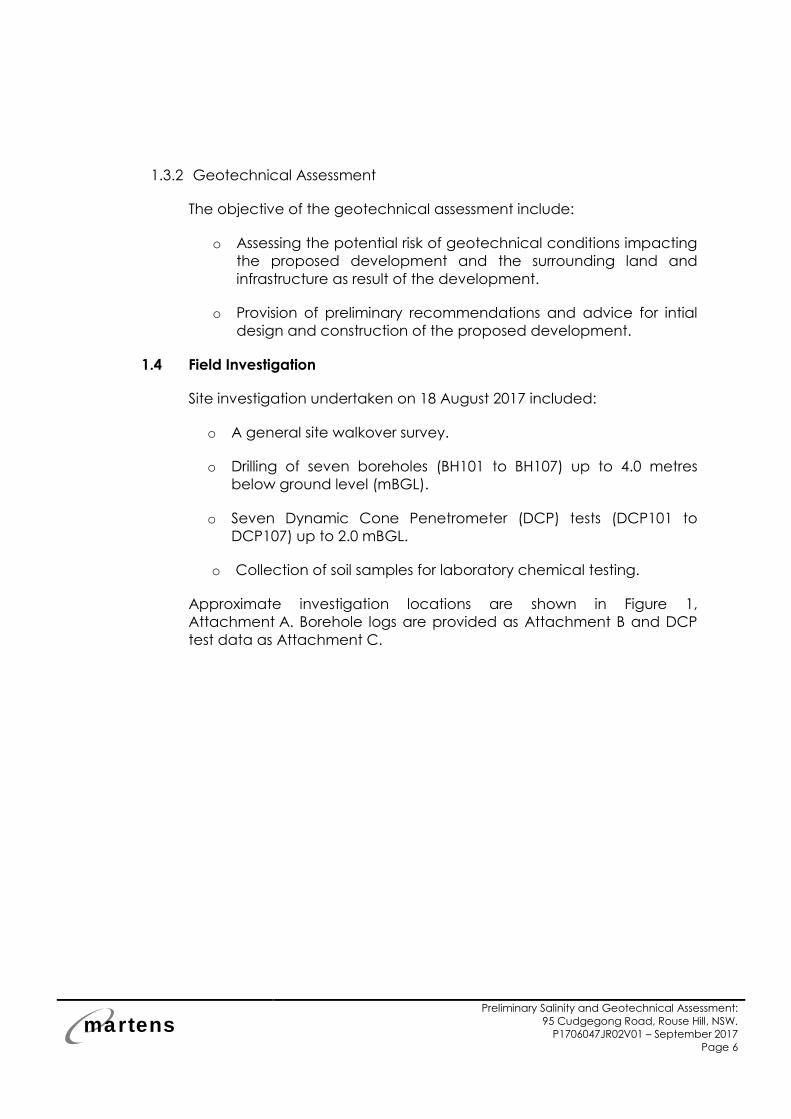
1.3.2 Geotechnical Assessment
The objective of the geotechnical assessment include:
o Assessing the potential risk of geotechnical conditions impacting
the proposed development and the surrounding land and
infrastructure as result of the development.
o Provision of preliminary recommendations and advice for intial
design and construction of the proposed development.
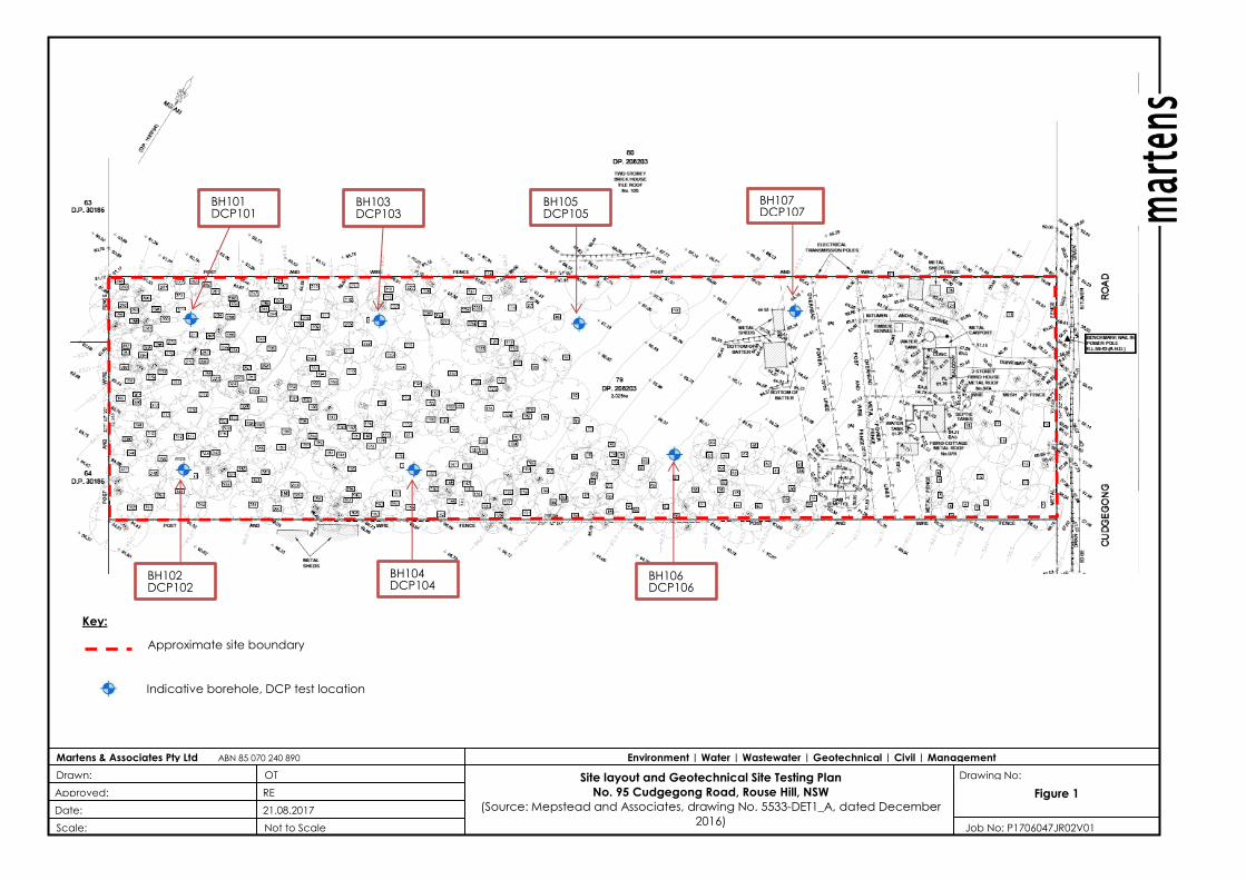
1.4 Field Investigation
Site investigation undertaken on 18 August 2017 included:
o A general site walkover survey.
o Drilling of seven boreholes (BH101 to BH107) up to 4.0 metres
below ground level (mBGL).
o Seven Dynamic Cone Penetrometer (DCP) tests (DCP101 to
DCP107) up to 2.0 mBGL.
o Collection of soil samples for laboratory chemical testing.
Approximate investigation locations are shown in Figure 1,
Attachment A. Borehole logs are provided as Attachment B and DCP
test data as Attachment C.
martens
Preliminary Salinity and Geotechnical Assessment:
95 Cudgegong Road, Rouse Hill, NSW.
P1706047JR02V01 – September 2017
Page 7
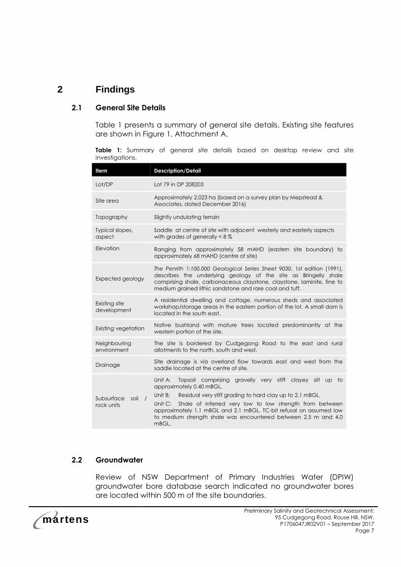
2 Findings
2.1 General Site Details
Table 1 presents a summary of general site details. Existing site features
are shown in Figure 1, Attachment A.
Table 1: Summary of general site details based on desktop review and site
investigations.
Item Description/Detail
Lot/DP Lot 79 in DP 208203
Site area Approximately 2.023 ha (based on a survey plan by Mepstead &
Associates, dated December 2016)
Topography Slightly undulating terrain
Typical slopes,
aspect
Saddle at centre of site with adjacent westerly and easterly aspects
with grades of generally < 8 %
Elevation
Ranging from approximately 58 mAHD (eastern site boundary) to
approximately 68 mAHD (centre of site)
Expected geology
The Penrith 1:100,000 Geological Series Sheet 9030, 1st edition (1991),
describes the underlying geology of the site as Bringelly shale
comprising shale, carbonaceous claystone, claystone, laminite, fine to
medium grained lithic sandstone and rare coal and tuff.
Existing site
development
A residential dwelling and cottage, numerous sheds and associated
workshop/storage areas in the eastern portion of the lot. A small dam is
located in the south east.
Existing vegetation Native bushland with mature trees located predominantly at the
western portion of the site.
Neighbouring
environment
The site is bordered by Cudgegong Road to the east and rural
allotments to the north, south and west.
Drainage Site drainage is via overland flow towards east and west from the
saddle located at the centre of site.
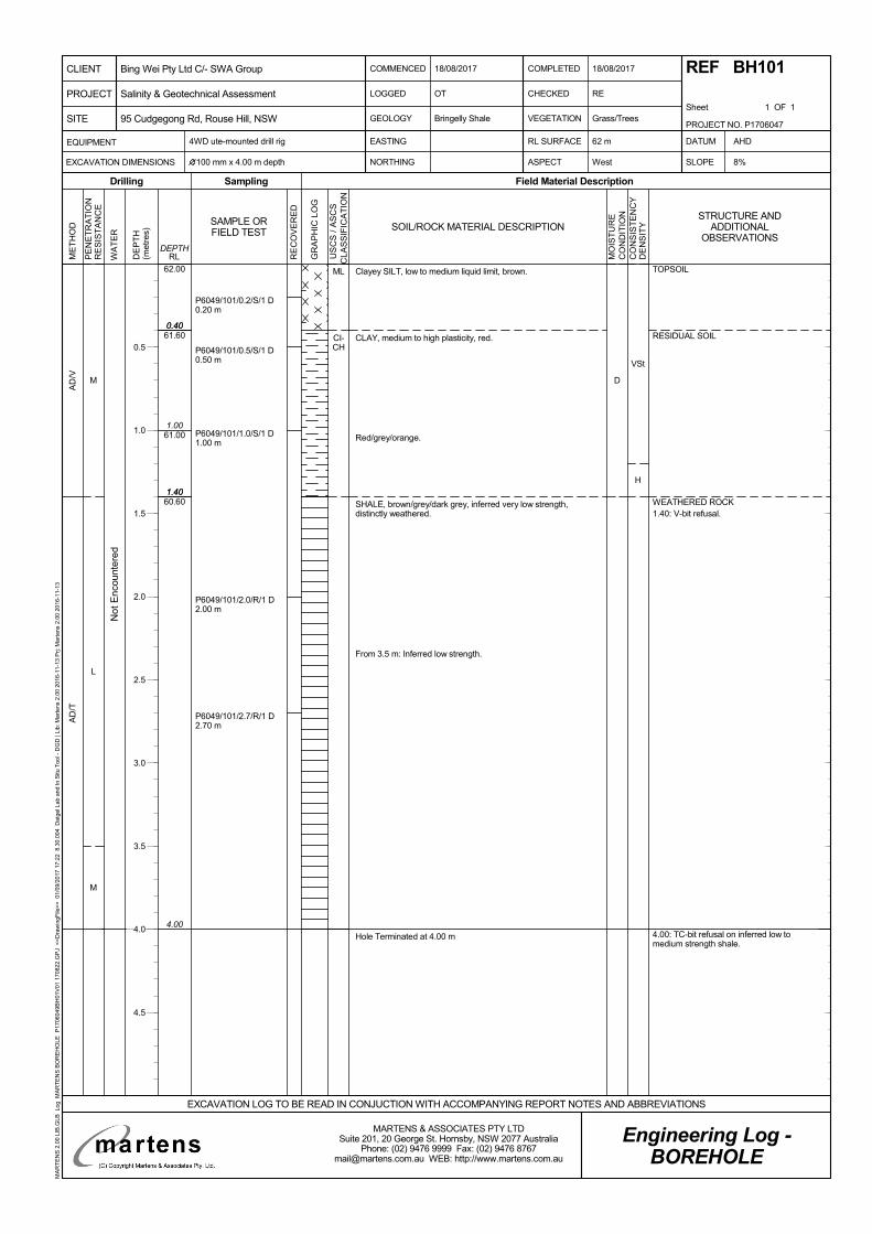
Subsurface soil /
rock units
Unit A: Topsoil comprising gravelly very stiff clayey silt up to
approximately 0.40 mBGL.
Unit B: Residual very stiff grading to hard clay up to 2.1 mBGL.
Unit C: Shale of inferred very low to low strength from between
approximately 1.1 mBGL and 2.1 mBGL. TC-bit refusal on assumed low
to medium strength shale was encountered between 2.5 m and 4.0
mBGL.
2.2 Groundwater
Review of NSW Department of Primary Industries Water (DPIW)
groundwater bore database search indicated no groundwater bores
are located within 500 m of the site boundaries.

martens
Preliminary Salinity and Geotechnical Assessment:
95 Cudgegong Road, Rouse Hill, NSW.
P1706047JR02V01 – September 2017
Page 8
Groundwater inflow was not observed in the boreholes up to
investigation termination depth of 4.0 mBGL.
Given the site elevation and field investigation results, it is expected
that limited excavations will not intercept the permanent groundwater
table.
Should further information on permanent site groundwater levels be
required, additional investigation would need to be carried out (i.e.
installation of groundwater monitoring bores).
martens
Preliminary Salinity and Geotechnical Assessment:
95 Cudgegong Road, Rouse Hill, NSW.
P1706047JR02V01 – September 2017
Page 9
3 Salinity Assessment
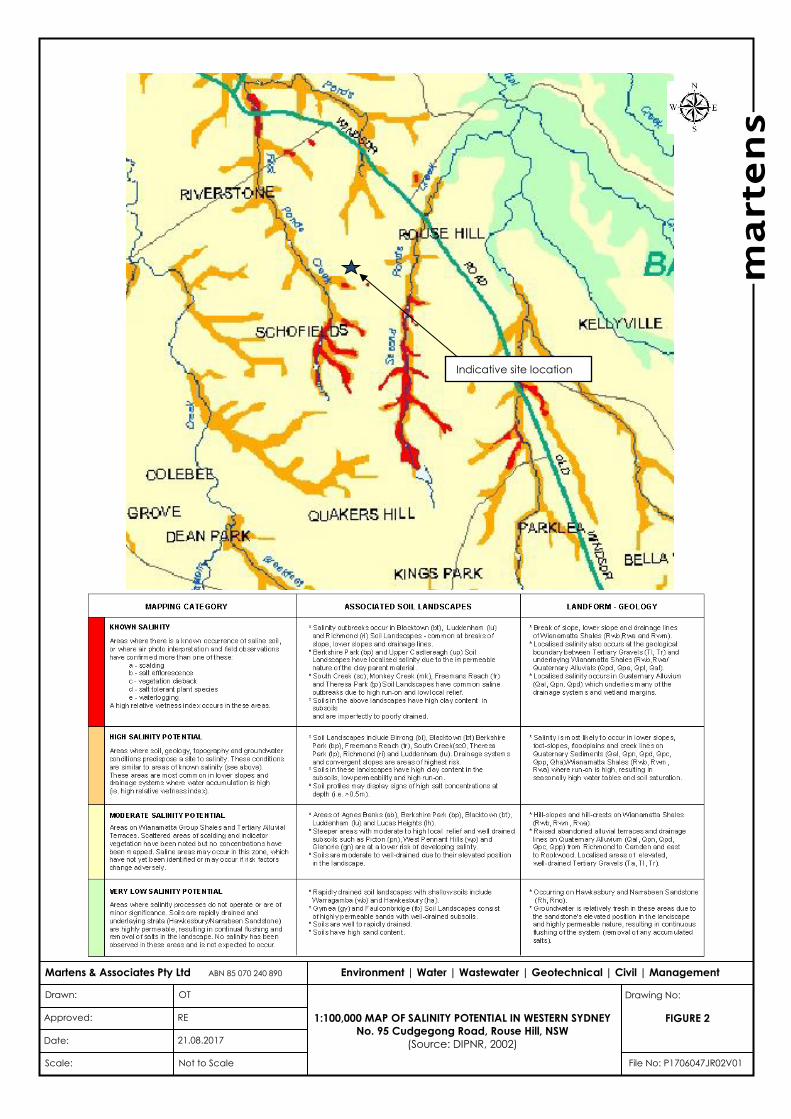
3.1 Documented Salinity Risk Potential
The 1:100,000 Salinity Potential in Western Sydney Map (DIPNR, 2002)
indicates the site to be located in an area of moderate salinity
potential (Figure 2, Attachment A).
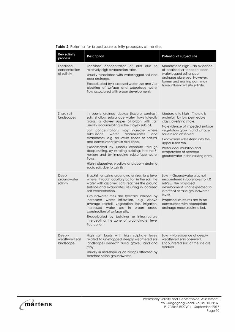
3.2 Broad Scale Salinity Processes
In producing the Salinity Potential Map, the Western Sydney Regional
Organisation of Councils (WSROC) developed a number of alternative
models of processes by which salinity may occur in Western Sydney
(WSROC, 2003, pgs. 16 to 20).
A list of key broad scale salinity processes likely to impact the site,
including summarised descriptions of each process, is presented in
Table 2.
3.3 Signs of Potential Saline Soils at the site
No obvious signs of saline conditions were observed across the site:
o Vegetation growth appeared healthy and uninhibited.
o No water marks or salt crystals were observed on the ground
surface.
o Site surface drainage appeared generally good.
o No evidence of concentrated surface erosion was observed.
3.4 Assessed Salinity Risk Potential
In Table 2, the broad scale salinity processes have been assessed in
terms of likelihood of occurring at the site, considering the proposed
development, site observations and investigation findings.
martens
Preliminary Salinity and Geotechnical Assessment:
95 Cudgegong Road, Rouse Hill, NSW.
P1706047JR02V01 – September 2017
Page 10
Table 2: Potential for broad scale salinity processes at the site.
Key salinity
process Description Potential at subject site
Localised
concentration
of salinity
Localised concentration of salts due to
relatively high evaporation rates.
Usually associated with waterlogged soil and
poor drainage.
Exacerbated by increased water use and / or
blocking of surface and subsurface water
flow associated with urban development.
Moderate to High – No evidence
of localised salt concentration,
waterlogged soil or poor
drainage observed. However,
former and existing dam may
have influenced site salinity.
Shale soil
landscapes
In poorly drained duplex (texture contrast)
soils, shallow subsurface water flows laterally
across a clayey upper B-Horizon with salt
usually accumulating in the clayey subsoil.
Salt concentrations may increase where
subsurface water accumulates and
evaporates, e.g. on lower slopes or natural
and constructed flats in mid-slope.
Exacerbated by subsoils exposure through
deep cutting, by installing buildings into the B-
horizon and by impeding subsurface water
flows.
Highly dispersive, erodible and poorly draining
sodic soils due to salinity.
Moderate to high – The site is
underlain by low permeable
clays, overlying shale.
No evidence of impeded surface
vegetation growth and surface
soil erosion observed.
Excavations will extend into the
upper B-horizon.
Water accumulation and
evaporation of perched
groundwater in the existing dam.
Deep
groundwater
salinity
Brackish or saline groundwater rises to a level
where, through capillary action in the soil, the
water with dissolved salts reaches the ground
surface and evaporates, resulting in localised
salt concentration.
Groundwater rises are typically caused by
increased water infiltration, e.g. above
average rainfall, vegetation loss, irrigation,
increased water use in urban areas,
construction of surface pits.
Exacerbated by buildings or infrastructure
intercepting the zone of groundwater level
fluctuation.
Low – Groundwater was not
encountered in boreholes to 4.0
mBGL. The proposed
development is not expected to
intercept or raise groundwater
levels.
Proposed structures are to be
constructed with appropriate
drainage measures installed.
Deeply
weathered soil
landscape
High salt loads with high sulphate levels
related to un-mapped deeply weathered soil
landscapes beneath fluvial gravel, sand and
clay.
Usually in mid-slope or on hilltops affected by
perched saline groundwater.
Low – No evidence of deeply
weathered soils observed.
Encountered soils at the site are
residual.

martens
Preliminary Salinity and Geotechnical Assessment:
95 Cudgegong Road, Rouse Hill, NSW.
P1706047JR02V01 – September 2017
Page 11
3.5 Laboratory Testing
3.5.1 Overview
Eighteen soil samples were collected from the boreholes and submitted to Envirolab Services, a National Association of Testing Authorities (NATA) accredited laboratory, for salinity and aggressivity testing (Electrical Conductivity (EC), pH and soluble SO4). The testing was carried out for salinity classification and to assess an exposure classification for design of buried concrete structures. Sampling was targeted to achieve a representative coverage of site conditions in line with assessed subsurface profiles, proposed earthworks and the limited investigation scope.
3.5.2 Results – Salinity Classification
Laboratory test results for salinity classification are summarised in Table
3. A laboratory test certificate is provided in Attachment D.
Table 3: Salinity test results.
Sample ID 1 Material EC(1:5)
(dS/m)
ECe
(dS/m) 2 Salinity Classification 3
6047/BH101/0.2 Clayey Silt 0.030 0.27 Non – Saline
6047/BH101/0.5 Clay 0.051 0.36 Non – Saline
6047/BH101/1.0 Clay 0.061 0.43 Non – Saline
6047/BH102/0.1 Clayey Silt 0.034 0.31 Non – Saline
6047/BH102/0.5 Clay 0.041 0.29 Non – Saline
6047/BH102/1.0 Clay 0.180 1.26 Non – Saline
6047/BH103/0.1 Clayey Silt 0.042 0.38 Non – Saline
6047/BH103/0.5 Clay 0.120 0.84 Non – Saline
6047/BH103/1.0 Clay 0.230 1.61 Non – Saline
6047/BH104/0.1 Clayey Silt 0.046 0.41 Non – Saline
6047/BH104/0.5 Clay 0.096 0.67 Non – Saline
6047/BH104/1.0 Clay 0.300 2.10 Slightly – Saline
6047/BH106/0.1 Clayey Silt 0.024 0.22 Non – Saline
6047/BH106/0.5 Clay 0.069 0.48 Non – Saline
6047/BH106/1.0 Clay 0.110 0.77 Non – Saline
6047/BH107/0.1 Clayey Silt 0.021 0.19 Non – Saline

martens
Preliminary Salinity and Geotechnical Assessment:
95 Cudgegong Road, Rouse Hill, NSW.
P1706047JR02V01 – September 2017
Page 12
Sample ID 1 Material EC(1:5)
(dS/m)
ECe
(dS/m) 2 Salinity Classification 3
6047/BH107/0.5 Clay 0.037 0.26 Non – Saline
6047/BH107/1.0 Clay 0.035 0.25 Non – Saline
Notes:
1 Project#/Borehole#/Depth (mBGL)
2 Based on EC to ECe multiplication factors from Table 6.1 in DLWC (2002).
3 Based on Table 6.2 of DLWC (2002) where ECe <2 dS/m = non-saline, ECe of 2-4 dS/m = slightly
saline, ECe of 4-8 dS/m = moderately saline, ECe of 8-16 dS/m = very saline and ECe of >16 dS/m
= highly saline.
Results indicate sub-surface materials at the site can generally be
categorised as non-saline. One sample at 1.0 mBGL in BH104 tested as
slightly saline. For the purpose of this report, we have assumed the site
to be non-saline, subject to results of further assessment, in particular
BH104.
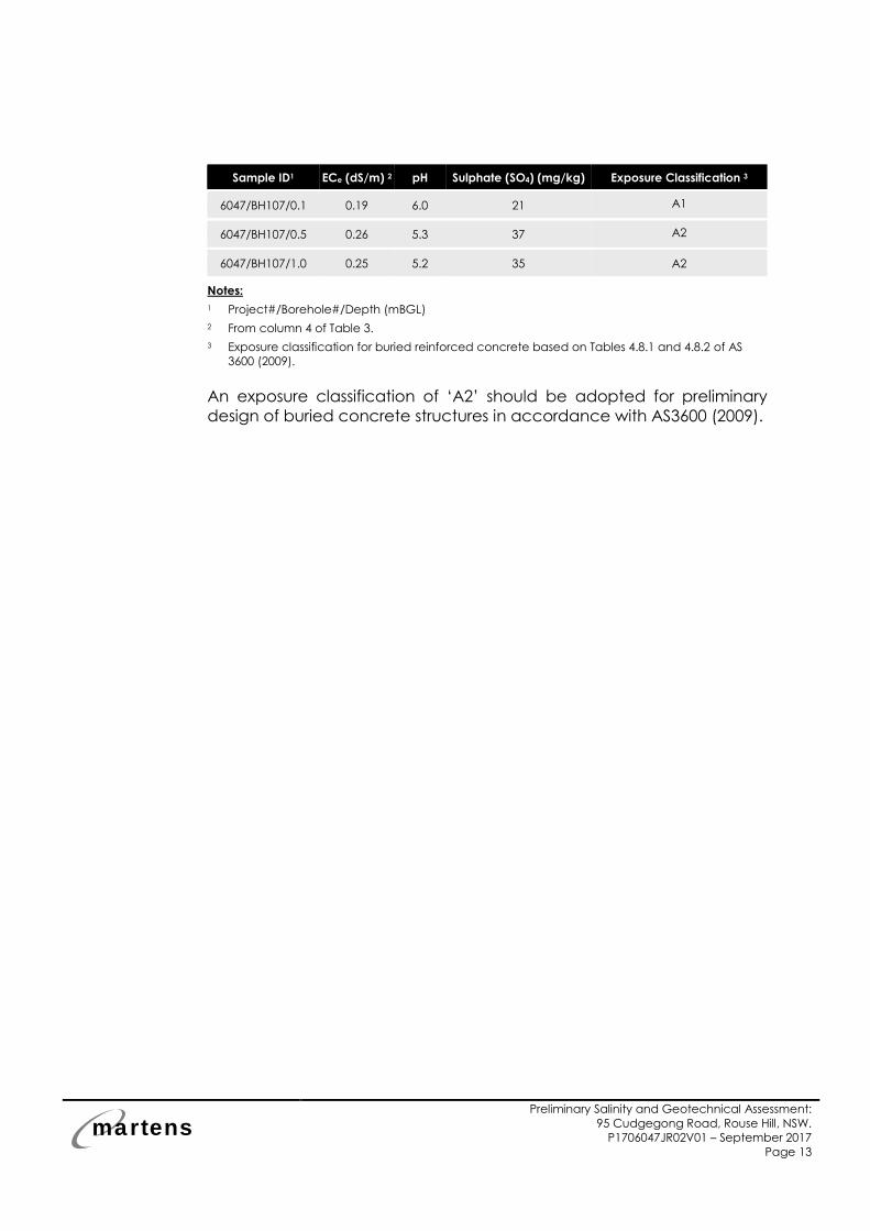
3.5.3 Results – Exposure Classification
Test results for exposure classification are summarised in Table 4. The
laboratory test certificate is provided in Attachment D.
Table 4: Exposure classification test results.
Sample ID1 ECe (dS/m) 2 pH Sulphate (SO4) (mg/kg) Exposure Classification 3
6047/BH101/0.2 0.27 4.8 10 A2
6047/BH101/0.5 0.36 4.8 56 A2
6047/BH101/1.0 0.43 4.9 41 A2
6047/BH102/0.1 0.31 5.3 <10 A2
6047/BH102/0.5 0.29 5.1 21 A2
6047/BH102/1.0 1.26 4.8 66 A2
6047/BH103/0.1 0.38 5.1 <10 A2
6047/BH103/0.5 0.84 4.8 53 A2
6047/BH103/1.0 1.61 4.9 66 A2
6047/BH104/0.1 0.41 4.9 10 A2
6047/BH104/0.5 0.67 4.8 53 A2
6047/BH104/1.0 2.10 4.8 95 A2
6047/BH106/0.1 0.22 5.4 <10 A2
6047/BH106/0.5 0.48 4.8 73 A2
6047/BH106/1.0 0.77 4.7 93 A2
martens
Preliminary Salinity and Geotechnical Assessment:
95 Cudgegong Road, Rouse Hill, NSW.
P1706047JR02V01 – September 2017
Page 13
Sample ID1 ECe (dS/m) 2 pH Sulphate (SO4) (mg/kg) Exposure Classification 3
6047/BH107/0.1 0.19 6.0 21 A1
6047/BH107/0.5 0.26 5.3 37 A2
6047/BH107/1.0 0.25 5.2 35 A2
Notes:
1 Project#/Borehole#/Depth (mBGL)
2 From column 4 of Table 3.
3 Exposure classification for buried reinforced concrete based on Tables 4.8.1 and 4.8.2 of AS
3600 (2009).
An exposure classification of ‘A2’ should be adopted for preliminary
design of buried concrete structures in accordance with AS3600 (2009).

martens
Preliminary Salinity and Geotechnical Assessment:
95 Cudgegong Road, Rouse Hill, NSW.
P1706047JR02V01 – September 2017
Page 14
4 Recommendations and Future Works
4.1 Geotechnical Recommendations
General geotechnical recommendations for the proposed
development are provided in Attachment E. Additional
recommendations are as follows:
1. Footing Systems: New building loads should be transmitted to
residual clay or underlying rock.
For shallow footings, preliminary allowable end bearing
capacities of 200 kPa and 350 kPa may be adopted for very stiff
to hard clay and rock, respectively, subject to minimum 300 mm
embedment into design material.
Alternatively, should higher bearing capacities be required,
deepened footings founding in rock with allowable end bearing
capacities of 700 kPa and 1000 kPa and allowable shaft frictions
of 60 kPa and 150 kPa may be adopted for very low to low
strength rock and low to medium strength rock respectively.
Recommended bearing capacities are subject to at least 500
mm embedment into design material. Further testing is required,
should higher bearing pressures be required.
2. Earth Pressure Coefficients: Preliminary design, if required, may
adopt preliminary active, at rest and passive earth pressure
coefficients for residual soil of 0.36, 0.53 and 2.77, respectively.
3. Site Classification: A preliminary site classification of ‘H1’ should
be adopted in accordance with AS 2870 (2011). This
classification is subject to the recommendations presented in this
report and the design of footings in accordance with the
relevant Australian Standards and guidelines.
martens
Preliminary Salinity and Geotechnical Assessment:
95 Cudgegong Road, Rouse Hill, NSW.
P1706047JR02V01 – September 2017
Page 15
5 Proposed Additional Assessments
5.1 Proposed Additional Assessment
We recommend the following additional assessments are carried out
during development of final design and prior to construction to better
manage geotechnical risks, where applicable:
o Laboratory testing of soil and rock, as necessary, for more
accurate assessment of subsurface conditions at future building
and infrastructure locations and of associated design
parameters, including shrink/swell and Atterberg Limit laboratory
testing, and to confirm or alter preliminary site classification and
design assumptions.
o Assessment of site specific foundation material capacity to
support adopted footing types.
o Review of final design and construction staging plans by a
Geotechnical Engineer to confirm adequate consideration of
the geotechnical risks and adoption of recommendations
provided in this report.
o Further salinity testing to confirm preliminary salinity and exposure
classifications and to delineate salinity conditions across soil
profiles, in particular in the vicinity of BH104, and development
areas, considering final development details.
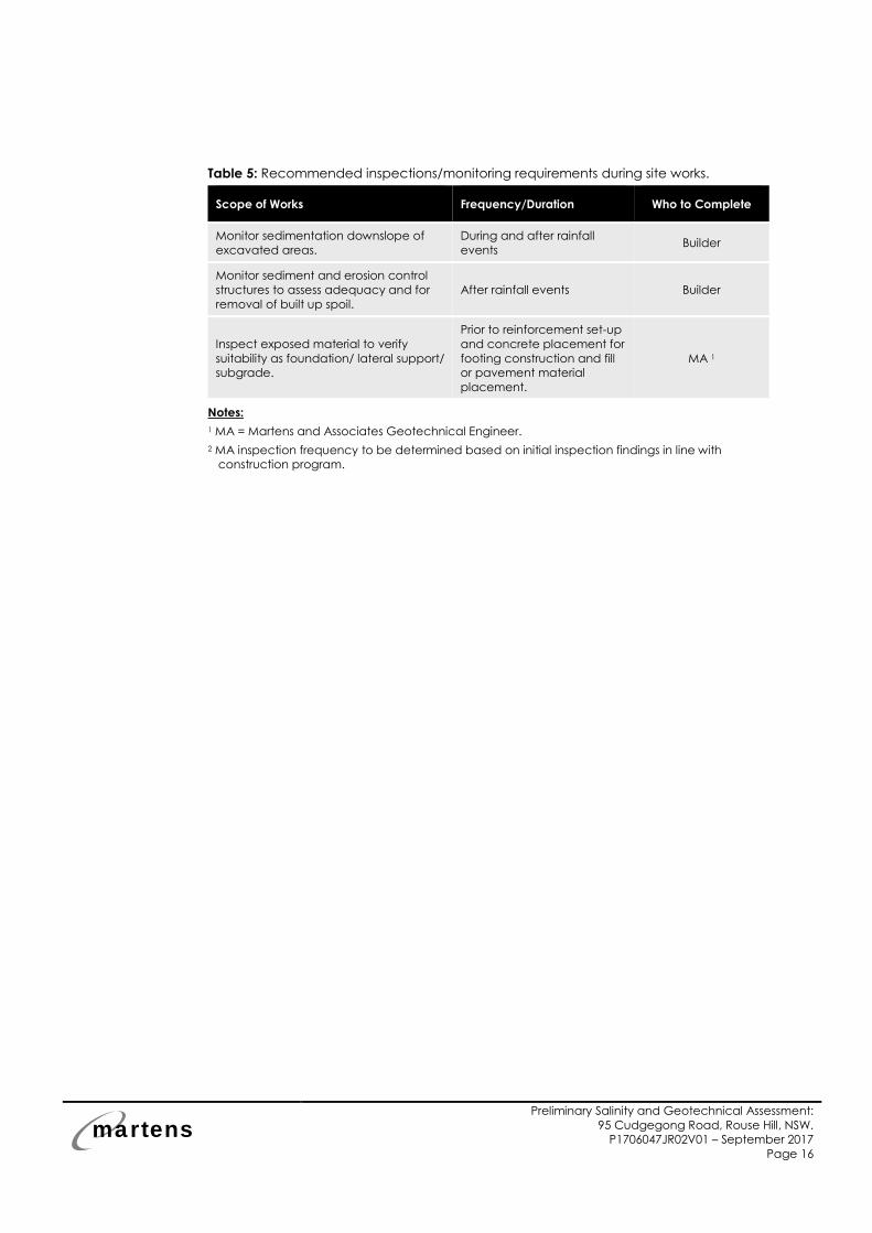
5.2 Proposed Monitoring and Inspection Program
To maintain site stability during site works and limit adverse
geotechnical impacts on the site and surrounding areas as a result of
the proposed development, we recommend the following is inspected
and monitored (Table 5) during site works. This program may be
updated following further detailed investigations.
martens
Preliminary Salinity and Geotechnical Assessment:
95 Cudgegong Road, Rouse Hill, NSW.
P1706047JR02V01 – September 2017
Page 16
Table 5: Recommended inspections/monitoring requirements during site works.
Scope of Works Frequency/Duration Who to Complete
Monitor sedimentation downslope of
excavated areas.
During and after rainfall
events Builder
Monitor sediment and erosion control
structures to assess adequacy and for
removal of built up spoil.
After rainfall events Builder
Inspect exposed material to verify
suitability as foundation/ lateral support/
subgrade.
Prior to reinforcement set-up
and concrete placement for
footing construction and fill
or pavement material
placement.
MA 1
Notes:
1 MA = Martens and Associates Geotechnical Engineer.
2 MA inspection frequency to be determined based on initial inspection findings in line with
construction program.

martens
Preliminary Salinity and Geotechnical Assessment:
95 Cudgegong Road, Rouse Hill, NSW.
P1706047JR02V01 – September 2017
Page 17
6 References
Australia Standard 1289.6.3.2 (AS, 1997) Determination of the
penetration resistance of a soil - 9kg dynamic cone penetrometer test.
Australia Standard 1726 (AS, 2017) Geotechnical site investigations.
Australia Standard 2870 (AS, 2011) Australia Standard, Residential slabs
and footings.
Australia Standard 3600 (AS, 2009) Concrete structures.
Australia Standard 3798 (AS, 2007) Guidelines on earthworks for
commercial and residential developments.
CSIRO BTF 18 (2003) Foundation Maintenance and Footing
Performance: A homeowner’s Guide.
Department of Infrastructure Planning and Natural Resources (DIPNR,
2002) Salinity Potential in Western Sydney Map.
Department of Land and Water Conservation (DLWC, 2002) Site
investigations for urban salinity.
Landcom (2004) Managing Urban Stormwater: Soils and Construction.
Mepstead & Associates (2016) Plan of detail & levels over Lot 79 in
D.P.208203, Drawing No. 5533-DET_A, dated 7 December 2016.
Penrith 1:100,000 Geological Series Sheet 9030, 1st edition (1991),
Geological Survey of New South Wales, Sydney.
SWA Group (2017) Ground level & Level 1-3 Floorplan, Job No.1703,
Drawing No. DA-12/A, dated 28 March 2017.
Western Sydney Regional Organisation of Councils (WSROC, 2003)
Western Sydney Salinity Code of Practice.

martens
Preliminary Salinity and Geotechnical Assessment:
95 Cudgegong Road, Rouse Hill, NSW.
P1706047JR02V01 – September 2017
Page 18
7 Attachment A – Figures
mar
tens
Drawn:
Approved:
Date:
Scale:
OT
RE
21.08.2017
Not to Scale Job No: P1706047JR02V01
Environment | Water | Wastewater | Geotechnical | Civil | Management Martens & Associates Pty Ltd ABN 85 070 240 890
Figure 1
Drawing No: Site layout and Geotechnical Site Testing Plan
No. 95 Cudgegong Road, Rouse Hill, NSW
(Source: Mepstead and Associates, drawing No. 5533-DET1_A, dated December
2016)
BH101 DCP101
Indicative borehole, DCP test location
Key:
Approximate site boundary
BH107 DCP107
BH102 DCP102
BH103 DCP103
BH104 DCP104
BH105 DCP105
BH106 DCP106
martens
Preliminary Salinity and Geotechnical Assessment:
95 Cudgegong Road, Rouse Hill, NSW.
P1706047JR02V01 – September 2017
Page 20
Indicative site location
marten
s
Drawn:
Approved:
Date:
Scale:
OT
RE
21.08.2017
Not to Scale File No: P1706047JR02V01
Environment | Water | Wastewater | Geotechnical | Civil | Management Martens & Associates Pty Ltd ABN 85 070 240 890
FIGURE 2
Drawing No:
1:100,000 MAP OF SALINITY POTENTIAL IN WESTERN SYDNEY
No. 95 Cudgegong Road, Rouse Hill, NSW
(Source: DIPNR, 2002)

martens
Preliminary Salinity and Geotechnical Assessment:
95 Cudgegong Road, Rouse Hill, NSW.
P1706047JR02V01 – September 2017
Page 21
8 Attachment B – Test Borehole Logs
VSt
H
0.40
1.40
4.00
62.00
61.60
61.00
60.60
0.40
1.00
1.40
M
L
M
AD
/VA
D/T
D
P6049/101/0.2/S/1 D0.20 m
P6049/101/0.5/S/1 D0.50 m
P6049/101/1.0/S/1 D1.00 m
P6049/101/2.0/R/1 D2.00 m
P6049/101/2.7/R/1 D2.70 m
Clayey SILT, low to medium liquid limit, brown.
CLAY, medium to high plasticity, red.
Red/grey/orange.
SHALE, brown/grey/dark grey, inferred very low strength,distinctly weathered.
From 3.5 m: Inferred low strength.
Hole Terminated at 4.00 m
ML
CI-CH
Not
Enc
ount
ered
TOPSOIL
RESIDUAL SOIL
WEATHERED ROCK1.40: V-bit refusal.
4.00: TC-bit refusal on inferred low tomedium strength shale.
PE
NE
TR
AT
ION
RE
SIS
TA
NC
E
WA
TE
R
DE
PT
H(m
etre
s)
Sampling
RE
CO
VE
RE
D
Field Material Description
RLDEPTH
ME
TH
OD
Drilling
GR
AP
HIC
LO
G
SAMPLE ORFIELD TEST SOIL/ROCK MATERIAL DESCRIPTION
MO
IST
UR
EC
ON
DIT
ION
CO
NS
IST
EN
CY
DE
NS
ITY
U
SC
S /
AS
CS
CLA
SS
IFIC
AT
ION
COMMENCED
LOGGED
GEOLOGY
18/08/2017
CHECKED
VEGETATION
RE
Grass/Trees
4WD ute-mounted drill rig
NORTHING ASPECT West SLOPE
Bringelly Shale
OT
COMPLETED
Sheet 1 OF 1
EASTING DATUM
100 mm x 4.00 m depth 8%
AHDEQUIPMENT
EXCAVATION DIMENSIONS
RL SURFACE
Engineering Log -BOREHOLE
18/08/2017 REF BH101
62 m
EXCAVATION LOG TO BE READ IN CONJUCTION WITH ACCOMPANYING REPORT NOTES AND ABBREVIATIONS
PROJECT NO. P1706047
PROJECT
CLIENT
SITE
Bing Wei Pty Ltd C/- SWA Group
95 Cudgegong Rd, Rouse Hill, NSW
Salinity & Geotechnical Assessment
MARTENS & ASSOCIATES PTY LTDSuite 201, 20 George St. Hornsby, NSW 2077 Australia
Phone: (02) 9476 9999 Fax: (02) 9476 [email protected] WEB: http://www.martens.com.au
MA
RT
EN
S 2
.00
LIB
.GLB
Log
MA
RT
EN
S B
OR
EH
OLE
P17
0604
9BH
01V
01 1
7082
2.G
PJ
<<
Dra
win
gFile
>>
01/
09/2
017
17:2
2 8
.30.
004
Dat
gel L
ab a
nd In
Situ
Too
l - D
GD
| Li
b: M
arte
ns 2
.00
2016
-11-
13 P
rj: M
arte
ns 2
.00
2016
-11-
13
STRUCTURE ANDADDITIONAL
OBSERVATIONS
0.5
1.0
1.5
2.0
2.5
3.0
3.5
4.0
4.5
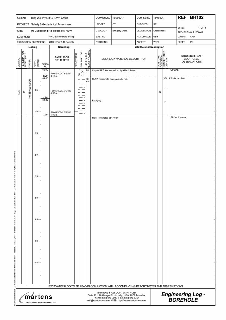
VSt
H
0.20
1.10
65.00
64.80
64.30
0.20
0.70
M
AD
/V
D
P6049/102/0.1/S/1 D0.10 m
P6049/102/0.5/S/1 D0.50 m
P6049/102/1.0/S/1 D1.00 m
Clayey SILT, low to medium liquid limit, brown.
CLAY, medium to high plasticity, red.
Red/grey.
Hole Terminated at 1.10 m
ML
CI-CH
Not
Enc
ount
ered
TOPSOIL
RESIDUAL SOIL
1.10: V-bit refusal.
PE
NE
TR
AT
ION
RE
SIS
TA
NC
E
WA
TE
R
DE
PT
H(m
etre
s)
Sampling
RE
CO
VE
RE
D
Field Material Description
RLDEPTH
ME
TH
OD
Drilling
GR
AP
HIC
LO
G
SAMPLE ORFIELD TEST SOIL/ROCK MATERIAL DESCRIPTION
MO
IST
UR
EC
ON
DIT
ION
CO
NS
IST
EN
CY
DE
NS
ITY
U
SC
S /
AS
CS
CLA
SS
IFIC
AT
ION
COMMENCED
LOGGED
GEOLOGY
18/08/2017
CHECKED
VEGETATION
RE
Grass/Trees
4WD ute-mounted drill rig
NORTHING ASPECT West SLOPE
Bringelly Shale
OT
COMPLETED
Sheet 1 OF 1
EASTING DATUM
100 mm x 1.10 m depth 8%
AHDEQUIPMENT
EXCAVATION DIMENSIONS
RL SURFACE
Engineering Log -BOREHOLE
18/08/2017 REF BH102
65 m
EXCAVATION LOG TO BE READ IN CONJUCTION WITH ACCOMPANYING REPORT NOTES AND ABBREVIATIONS
PROJECT NO. P1706047
PROJECT
CLIENT
SITE
Bing Wei Pty Ltd C/- SWA Group
95 Cudgegong Rd, Rouse Hill, NSW
Salinity & Geotechnical Assessment
MARTENS & ASSOCIATES PTY LTDSuite 201, 20 George St. Hornsby, NSW 2077 Australia
Phone: (02) 9476 9999 Fax: (02) 9476 [email protected] WEB: http://www.martens.com.au
MA
RT
EN
S 2
.00
LIB
.GLB
Log
MA
RT
EN
S B
OR
EH
OLE
P17
0604
9BH
01V
01 1
7082
2.G
PJ
<<
Dra
win
gFile
>>
01/
09/2
017
17:2
2 8
.30.
004
Dat
gel L
ab a
nd In
Situ
Too
l - D
GD
| Li
b: M
arte
ns 2
.00
2016
-11-
13 P
rj: M
arte
ns 2
.00
2016
-11-
13
STRUCTURE ANDADDITIONAL
OBSERVATIONS
0.5
1.0
1.5
2.0
2.5
3.0
3.5
4.0
4.5
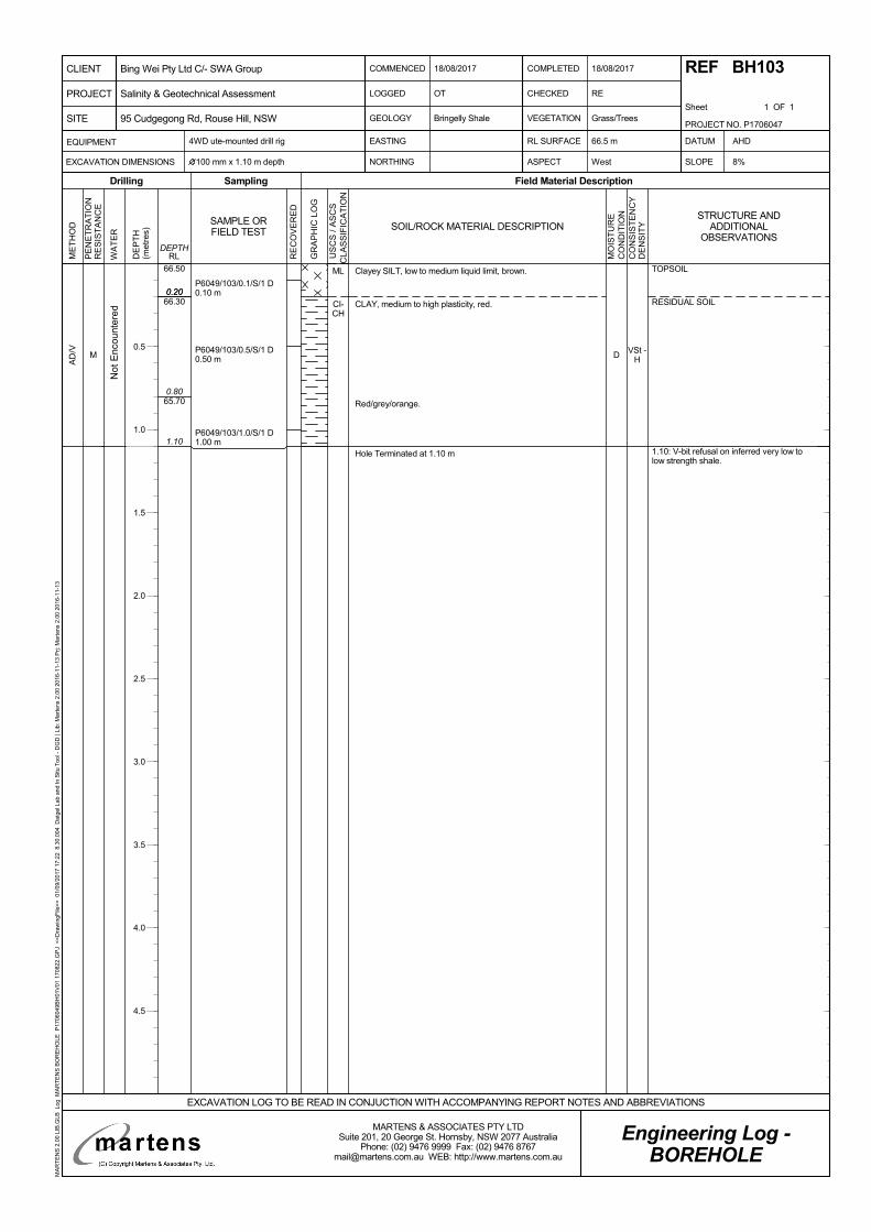
VSt -H
0.20
1.10
66.50
66.30
65.70
0.20
0.80
M
AD
/V
D
P6049/103/0.1/S/1 D0.10 m
P6049/103/0.5/S/1 D0.50 m
P6049/103/1.0/S/1 D1.00 m
Clayey SILT, low to medium liquid limit, brown.
CLAY, medium to high plasticity, red.
Red/grey/orange.
Hole Terminated at 1.10 m
ML
CI-CH
Not
Enc
ount
ered
TOPSOIL
RESIDUAL SOIL
1.10: V-bit refusal on inferred very low tolow strength shale.
PE
NE
TR
AT
ION
RE
SIS
TA
NC
E
WA
TE
R
DE
PT
H(m
etre
s)
Sampling
RE
CO
VE
RE
D
Field Material Description
RLDEPTH
ME
TH
OD
Drilling
GR
AP
HIC
LO
G
SAMPLE ORFIELD TEST SOIL/ROCK MATERIAL DESCRIPTION
MO
IST
UR
EC
ON
DIT
ION
CO
NS
IST
EN
CY
DE
NS
ITY
U
SC
S /
AS
CS
CLA
SS
IFIC
AT
ION
COMMENCED
LOGGED
GEOLOGY
18/08/2017
CHECKED
VEGETATION
RE
Grass/Trees
4WD ute-mounted drill rig
NORTHING ASPECT West SLOPE
Bringelly Shale
OT
COMPLETED
Sheet 1 OF 1
EASTING DATUM
100 mm x 1.10 m depth 8%
AHDEQUIPMENT
EXCAVATION DIMENSIONS
RL SURFACE
Engineering Log -BOREHOLE
18/08/2017 REF BH103
66.5 m
EXCAVATION LOG TO BE READ IN CONJUCTION WITH ACCOMPANYING REPORT NOTES AND ABBREVIATIONS
PROJECT NO. P1706047
PROJECT
CLIENT
SITE
Bing Wei Pty Ltd C/- SWA Group
95 Cudgegong Rd, Rouse Hill, NSW
Salinity & Geotechnical Assessment
MARTENS & ASSOCIATES PTY LTDSuite 201, 20 George St. Hornsby, NSW 2077 Australia
Phone: (02) 9476 9999 Fax: (02) 9476 [email protected] WEB: http://www.martens.com.au
MA
RT
EN
S 2
.00
LIB
.GLB
Log
MA
RT
EN
S B
OR
EH
OLE
P17
0604
9BH
01V
01 1
7082
2.G
PJ
<<
Dra
win
gFile
>>
01/
09/2
017
17:2
2 8
.30.
004
Dat
gel L
ab a
nd In
Situ
Too
l - D
GD
| Li
b: M
arte
ns 2
.00
2016
-11-
13 P
rj: M
arte
ns 2
.00
2016
-11-
13
STRUCTURE ANDADDITIONAL
OBSERVATIONS
0.5
1.0
1.5
2.0
2.5
3.0
3.5
4.0
4.5

VSt -H
0.30
1.30
2.70
67.00
66.70
66.20
66.00
65.70
0.30
0.80
1.00
1.30
M
H
AD
/VA
D/T
D
P6047/104/0.1/S/1 D0.10 m
P6047/104/0.5/S/1 D0.50 m
P6047/104/1.0/S/1 D1.00 m
P6047/104/2.1/R/1 D2.10 m
Clayey SILT, low to medium liquid limit, brown.
CLAY, medium to high plasticity, red.
More grey.
Grey/orange.
SHALE, dark grey, inferred low strength, distinctly weathered.
Hole Terminated at 2.70 m
ML
CI-CH
Not
Enc
ount
ered
TOPSOIL
RESIDUAL SOIL
WEATHERED ROCK1.30: V-bit refusal.
2.70: TC-bit refusal on inferred low tomedium strength shale.
PE
NE
TR
AT
ION
RE
SIS
TA
NC
E
WA
TE
R
DE
PT
H(m
etre
s)
Sampling
RE
CO
VE
RE
D
Field Material Description
RLDEPTH
ME
TH
OD
Drilling
GR
AP
HIC
LO
G
SAMPLE ORFIELD TEST SOIL/ROCK MATERIAL DESCRIPTION
MO
IST
UR
EC
ON
DIT
ION
CO
NS
IST
EN
CY
DE
NS
ITY
U
SC
S /
AS
CS
CLA
SS
IFIC
AT
ION
COMMENCED
LOGGED
GEOLOGY
18/08/2017
CHECKED
VEGETATION
RE
Grass/Trees
4WD ute-mounted drill rig
NORTHING ASPECT West SLOPE
Bringelly Shale
OT
COMPLETED
Sheet 1 OF 1
EASTING DATUM
100 mm x 2.70 m depth 5%
AHDEQUIPMENT
EXCAVATION DIMENSIONS
RL SURFACE
Engineering Log -BOREHOLE
18/08/2017 REF BH104
67 m
EXCAVATION LOG TO BE READ IN CONJUCTION WITH ACCOMPANYING REPORT NOTES AND ABBREVIATIONS
PROJECT NO. P1706047
PROJECT
CLIENT
SITE
Bing Wei Pty Ltd C/- SWA Group
95 Cudgegong Rd, Rouse Hill, NSW
Salinity & Geotechnical Assessment
MARTENS & ASSOCIATES PTY LTDSuite 201, 20 George St. Hornsby, NSW 2077 Australia
Phone: (02) 9476 9999 Fax: (02) 9476 [email protected] WEB: http://www.martens.com.au
MA
RT
EN
S 2
.00
LIB
.GLB
Log
MA
RT
EN
S B
OR
EH
OLE
P17
0604
9BH
01V
01 1
7082
2.G
PJ
<<
Dra
win
gFile
>>
01/
09/2
017
17:2
2 8
.30.
004
Dat
gel L
ab a
nd In
Situ
Too
l - D
GD
| Li
b: M
arte
ns 2
.00
2016
-11-
13 P
rj: M
arte
ns 2
.00
2016
-11-
13
STRUCTURE ANDADDITIONAL
OBSERVATIONS
0.5
1.0
1.5
2.0
2.5
3.0
3.5
4.0
4.5
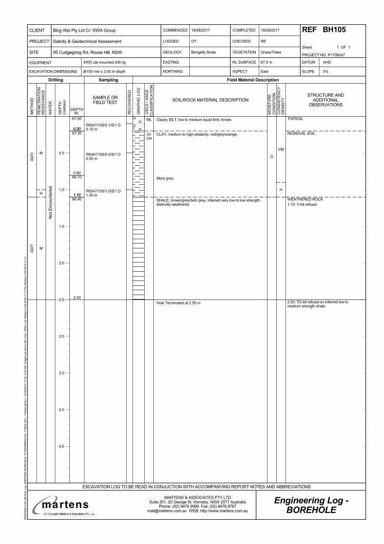
VSt
H
0.20
1.10
2.50
67.50
67.30
66.70
66.40
0.20
0.80
1.10
M
H
M
AD
/VA
D/T
D
P6047/105/0.1/S/1 D0.10 m
P6047/105/0.5/S/1 D0.50 m
P6047/105/1.0/S/1 D1.00 m
Clayey SILT, low to medium liquid limit, brown.
CLAY, medium to high plasticity, red/grey/orange.
More grey.
SHALE, brown/grey/dark grey, inferred very low to low strength,distinctly weathered.
Hole Terminated at 2.50 m
ML
CI-CH
Not
Enc
ount
ered
TOPSOIL
RESIDUAL SOIL
WEATHERED ROCK1.10: V-bit refusal.
2.50: TC-bit refusal on inferred low tomedium strength shale,
PE
NE
TR
AT
ION
RE
SIS
TA
NC
E
WA
TE
R
DE
PT
H(m
etre
s)
Sampling
RE
CO
VE
RE
D
Field Material Description
RLDEPTH
ME
TH
OD
Drilling
GR
AP
HIC
LO
G
SAMPLE ORFIELD TEST SOIL/ROCK MATERIAL DESCRIPTION
MO
IST
UR
EC
ON
DIT
ION
CO
NS
IST
EN
CY
DE
NS
ITY
U
SC
S /
AS
CS
CLA
SS
IFIC
AT
ION
COMMENCED
LOGGED
GEOLOGY
18/08/2017
CHECKED
VEGETATION
RE
Grass/Trees
4WD ute-mounted drill rig
NORTHING ASPECT East SLOPE
Bringelly Shale
OT
COMPLETED
Sheet 1 OF 1
EASTING DATUM
100 mm x 2.50 m depth 5%
AHDEQUIPMENT
EXCAVATION DIMENSIONS
RL SURFACE
Engineering Log -BOREHOLE
18/08/2017 REF BH105
67.5 m
EXCAVATION LOG TO BE READ IN CONJUCTION WITH ACCOMPANYING REPORT NOTES AND ABBREVIATIONS
PROJECT NO. P1706047
PROJECT
CLIENT
SITE
Bing Wei Pty Ltd C/- SWA Group
95 Cudgegong Rd, Rouse Hill, NSW
Salinity & Geotechnical Assessment
MARTENS & ASSOCIATES PTY LTDSuite 201, 20 George St. Hornsby, NSW 2077 Australia
Phone: (02) 9476 9999 Fax: (02) 9476 [email protected] WEB: http://www.martens.com.au
MA
RT
EN
S 2
.00
LIB
.GLB
Log
MA
RT
EN
S B
OR
EH
OLE
P17
0604
9BH
01V
01 1
7082
2.G
PJ
<<
Dra
win
gFile
>>
01/
09/2
017
17:2
2 8
.30.
004
Dat
gel L
ab a
nd In
Situ
Too
l - D
GD
| Li
b: M
arte
ns 2
.00
2016
-11-
13 P
rj: M
arte
ns 2
.00
2016
-11-
13
STRUCTURE ANDADDITIONAL
OBSERVATIONS
0.5
1.0
1.5
2.0
2.5
3.0
3.5
4.0
4.5

VSt
H
0.20
1.40
3.70
65.00
64.80
64.20
63.60
0.20
0.80
1.40
M
H
AD
/VA
D/T
D
P6047/106/0.1/S/1 D0.10 m
P6047/106/0.5/S/1 D0.50 m
P6047/106/1.0/S/1 D1.00 m
P6047/106/2.5/R/1 D2.50 m
Clayey SILT, low to medium liquid limit, brown.
CLAY, medium to high plasticity, red.
Red/grey.
SHALE, grey, inferred very low to low strength, distinctlyweathered.
Hole Terminated at 3.70 m
ML
CI-CH
Not
Enc
ount
ered
TOPSOIL
RESIDUAL SOIL
WEATHERED ROCK1.40: V-bit refusal.
3.70: TC-bit refusal on inferred low tomedium strength shale.
PE
NE
TR
AT
ION
RE
SIS
TA
NC
E
WA
TE
R
DE
PT
H(m
etre
s)
Sampling
RE
CO
VE
RE
D
Field Material Description
RLDEPTH
ME
TH
OD
Drilling
GR
AP
HIC
LO
G
SAMPLE ORFIELD TEST SOIL/ROCK MATERIAL DESCRIPTION
MO
IST
UR
EC
ON
DIT
ION
CO
NS
IST
EN
CY
DE
NS
ITY
U
SC
S /
AS
CS
CLA
SS
IFIC
AT
ION
COMMENCED
LOGGED
GEOLOGY
18/08/2017
CHECKED
VEGETATION
RE
Grass/Trees
4WD ute-mounted drill rig
NORTHING ASPECT East SLOPE
Bringelly Shale
OT
COMPLETED
Sheet 1 OF 1
EASTING DATUM
100 mm x 3.70 m depth 5%
AHDEQUIPMENT
EXCAVATION DIMENSIONS
RL SURFACE
Engineering Log -BOREHOLE
18/08/2017 REF BH106
65 m
EXCAVATION LOG TO BE READ IN CONJUCTION WITH ACCOMPANYING REPORT NOTES AND ABBREVIATIONS
PROJECT NO. P1706047
PROJECT
CLIENT
SITE
Bing Wei Pty Ltd C/- SWA Group
95 Cudgegong Rd, Rouse Hill, NSW
Salinity & Geotechnical Assessment
MARTENS & ASSOCIATES PTY LTDSuite 201, 20 George St. Hornsby, NSW 2077 Australia
Phone: (02) 9476 9999 Fax: (02) 9476 [email protected] WEB: http://www.martens.com.au
MA
RT
EN
S 2
.00
LIB
.GLB
Log
MA
RT
EN
S B
OR
EH
OLE
P17
0604
9BH
01V
01 1
7082
2.G
PJ
<<
Dra
win
gFile
>>
01/
09/2
017
17:2
2 8
.30.
004
Dat
gel L
ab a
nd In
Situ
Too
l - D
GD
| Li
b: M
arte
ns 2
.00
2016
-11-
13 P
rj: M
arte
ns 2
.00
2016
-11-
13
STRUCTURE ANDADDITIONAL
OBSERVATIONS
0.5
1.0
1.5
2.0
2.5
3.0
3.5
4.0
4.5

VSt
H
0.20
2.10
66.00
65.80
65.30
64.80
0.20
0.70
1.20
M
AD
/V
D
P6047/107/0.1/S/1 D0.10 m
P6047/107/0.5/S/1 D0.50 m
P6047/107/1.0/S/1 D1.00 m
P6047/107/1.5/S/1 D1.50 m
Clayey SILT, low to medium liquid limit, brown.
CLAY, medium to high plasticity, red.
Red/grey/orange.
Red/grey.
Hole Terminated at 2.10 m
ML
CI-CH
Not
Enc
ount
ered
TOPSOIL
RESIDUAL SOIL
2.10: V-bit refusal on inferred very low tolow strength shale.
PE
NE
TR
AT
ION
RE
SIS
TA
NC
E
WA
TE
R
DE
PT
H(m
etre
s)
Sampling
RE
CO
VE
RE
D
Field Material Description
RLDEPTH
ME
TH
OD
Drilling
GR
AP
HIC
LO
G
SAMPLE ORFIELD TEST SOIL/ROCK MATERIAL DESCRIPTION
MO
IST
UR
EC
ON
DIT
ION
CO
NS
IST
EN
CY
DE
NS
ITY
U
SC
S /
AS
CS
CLA
SS
IFIC
AT
ION
COMMENCED
LOGGED
GEOLOGY
18/08/2017
CHECKED
VEGETATION
RE
Grass/Trees
4WD ute-mounted drill rig
NORTHING ASPECT East SLOPE
Bringelly Shale
OT
COMPLETED
Sheet 1 OF 1
EASTING DATUM
100 mm x 2.10 m depth 5%
AHDEQUIPMENT
EXCAVATION DIMENSIONS
RL SURFACE
Engineering Log -BOREHOLE
18/08/2017 REF BH107
66 m
EXCAVATION LOG TO BE READ IN CONJUCTION WITH ACCOMPANYING REPORT NOTES AND ABBREVIATIONS
PROJECT NO. P1706047
PROJECT
CLIENT
SITE
Bing Wei Pty Ltd C/- SWA Group
95 Cudgegong Rd, Rouse Hill, NSW
Salinity & Geotechnical Assessment
MARTENS & ASSOCIATES PTY LTDSuite 201, 20 George St. Hornsby, NSW 2077 Australia
Phone: (02) 9476 9999 Fax: (02) 9476 [email protected] WEB: http://www.martens.com.au
MA
RT
EN
S 2
.00
LIB
.GLB
Log
MA
RT
EN
S B
OR
EH
OLE
P17
0604
9BH
01V
01 1
7082
2.G
PJ
<<
Dra
win
gFile
>>
01/
09/2
017
17:2
2 8
.30.
004
Dat
gel L
ab a
nd In
Situ
Too
l - D
GD
| Li
b: M
arte
ns 2
.00
2016
-11-
13 P
rj: M
arte
ns 2
.00
2016
-11-
13
STRUCTURE ANDADDITIONAL
OBSERVATIONS
0.5
1.0
1.5
2.0
2.5
3.0
3.5
4.0
4.5
martens
Preliminary Salinity and Geotechnical Assessment:
95 Cudgegong Road, Rouse Hill, NSW.
P1706047JR02V01 – September 2017
Page 29
9 Attachment C – DCP ‘N’ Counts

Dynamic Cone Penetrometer Test Log Summary
Depth Interval
(m)DCP101 DCP102 DCP103 DCP104 DCP105 DCP106 DCP107
0.15 9 15 23 18 12 12 27
0.30 12 13 22 15 12 12 19
0.45 16 14 16 18 10 14 12
0.60 15 19 17 18 7 15 13
0.75 12 29 20 18 22 18 11
0.90 9 29 16 25 15 14 9
1.05 9 21 23 18 27 15 11
1.20 17 26 16 / 50 mm 24 37 22 12
1.35 44 32 15 25 / 100 mm 13
1.50 30 8 / 50 mm 13
1.65 25 14
1.80 7 / 5 mm 32
1.95 26
2.10
2.25
2.40
2.55
2.70
2.85
3.00
P1706047JS01V01
Client Bing Wei Pty Ltd (Lily Liu) C/- SWA Group Log Date 18.08.17
DCP Group Reference95 Cudgegong Road, Rouse Hill, NSWSite
TEST DATA
OT
Checked by RE
Logged by
Comments DCP cone tip penetrated 50 mm into soil prior to testing.
Terminated at
2.0 m due to
high 'N' counts
Double Bounce at
1.40 m
Double Bounce
at 1.75 m
Double Bounce
at 1.15 m
Double Bounce at
1.45 m
Double Bounce
at 1.35 m
Terminated at 1.25
m due to high 'N'
counts
Suite 201, 20 George Street, Hornsby, NSW 2077, Ph: (02) 9476 9999 Fax: (02) 9476 8767, [email protected], www.martens.com.au
martens consulting engineers since 1989

martens
Preliminary Salinity and Geotechnical Assessment:
95 Cudgegong Road, Rouse Hill, NSW.
P1706047JR02V01 – September 2017
Page 31
10 Attachment D – Laboratory Test Certificate

Envirolab Services Pty Ltd
ABN 37 112 535 645
12 Ashley St Chatswood NSW 2067
ph 02 9910 6200 fax 02 9910 6201
www.envirolab.com.au
CERTIFICATE OF ANALYSIS 173920
Suite 201, 20 George St, Hornsby, NSW, 2077Address
Orson ThienAttention
Martens & Associates Pty LtdClient
Client Details
22/08/2017Date completed instructions received
22/08/2017Date samples received
18 soilsNumber of Samples
P1706047COC02V01Your Reference
Sample Details
Results are reported on a dry weight basis for solids and on an as received basis for other matrices.
Samples were analysed as received from the client. Results relate specifically to the samples as received.
Please refer to the following pages for results, methodology summary and quality control data.
Analysis Details
Tests not covered by NATA are denoted with *Accredited for compliance with ISO/IEC 17025 - Testing.
NATA Accreditation Number 2901. This document shall not be reproduced except in full.
28/08/2017Date of Issue
29/08/2017Date results requested by
Report Details
David Springer, General Manager
Authorised By
Priya Samarawickrama, Senior Chemist
Results Approved By
Revision No: R00
173920Envirolab Reference: Page | 1 of 6

Client Reference: P1706047COC02V01
4139<10mg/kgSulphate, SO4 1:5 soil:water
353721µS/cmElectrical Conductivity 1:5 soil:water
5.25.36.0pH UnitspH 1:5 soil:water
24/08/201724/08/201724/08/2017-Date analysed
24/08/201724/08/201724/08/2017-Date prepared
SoilSoilSoilType of sample
18/08/201718/08/201718/08/2017Date Sampled
6047/BH107/1.06047/BH107/0.56047/BH107/0.1UNITSYour Reference
173920-18173920-17173920-16Our Reference
Misc Inorg - Soil
9373<109553mg/kgSulphate, SO4 1:5 soil:water
110692430096µS/cmElectrical Conductivity 1:5 soil:water
4.74.85.44.84.8pH UnitspH 1:5 soil:water
24/08/201724/08/201724/08/201724/08/201724/08/2017-Date analysed
24/08/201724/08/201724/08/201724/08/201724/08/2017-Date prepared
SoilSoilSoilSoilSoilType of sample
18/08/201718/08/201718/08/201718/08/201718/08/2017Date Sampled
6047/BH106/1.06047/BH106/0.56047/BH106/0.16047/BH104/1.06047/BH104/0.5UNITSYour Reference
173920-15173920-14173920-13173920-12173920-11Our Reference
Misc Inorg - Soil
106653<1066mg/kgSulphate, SO4 1:5 soil:water
4623012042180µS/cmElectrical Conductivity 1:5 soil:water
4.94.94.85.14.8pH UnitspH 1:5 soil:water
24/08/201724/08/201724/08/201724/08/201724/08/2017-Date analysed
24/08/201724/08/201724/08/201724/08/201724/08/2017-Date prepared
SoilSoilSoilSoilSoilType of sample
18/08/201718/08/201718/08/201718/08/201718/08/2017Date Sampled
6047/BH104/0.16047/BH103/1.06047/BH103/0.56047/BH103/0.16047/BH102/1.0UNITSYour Reference
173920-10173920-9173920-8173920-7173920-6Our Reference
Misc Inorg - Soil
21<10415610mg/kgSulphate, SO4 1:5 soil:water
4134615130µS/cmElectrical Conductivity 1:5 soil:water
5.15.34.94.84.8pH UnitspH 1:5 soil:water
24/08/201724/08/201724/08/201724/08/201724/08/2017-Date analysed
24/08/201724/08/201724/08/201724/08/201724/08/2017-Date prepared
SoilSoilSoilSoilSoilType of sample
18/08/201718/08/201718/08/201718/08/201718/08/2017Date Sampled
6047/BH102/0.56047/BH102/0.16047/BH101/1.06047/BH101/0.56047/BH101/0.2UNITSYour Reference
173920-5173920-4173920-3173920-2173920-1Our Reference
Misc Inorg - Soil
Envirolab Reference: 173920
R00Revision No:
Page | 2 of 6

Client Reference: P1706047COC02V01
Anions - a range of Anions are determined by Ion Chromatography, in accordance with APHA latest edition, 4110-B. Alternatively determined by colourimetry/turbidity using Discrete Analyer.
Inorg-081
Conductivity and Salinity - measured using a conductivity cell at 25°C in accordance with APHA latest edition 2510 and Rayment & Lyons.
Inorg-002
pH - Measured using pH meter and electrode in accordance with APHA latest edition, 4500-H+. Please note that the results for water analyses are indicative only, as analysis outside of the APHA storage times.
Inorg-001
Methodology SummaryMethod ID
Envirolab Reference: 173920
R00Revision No:
Page | 3 of 6
Client Reference: P1706047COC02V01
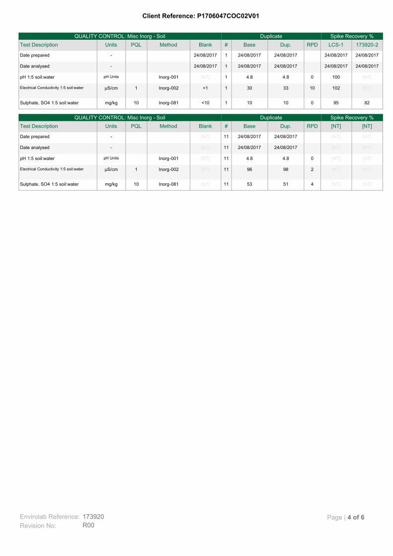
[NT][NT]4515311[NT]Inorg-08110mg/kgSulphate, SO4 1:5 soil:water
[NT][NT]2989611[NT]Inorg-0021µS/cmElectrical Conductivity 1:5 soil:water
[NT][NT]04.84.811[NT]Inorg-001pH UnitspH 1:5 soil:water
[NT][NT]24/08/201724/08/201711[NT]-Date analysed
[NT][NT]24/08/201724/08/201711[NT]-Date prepared
[NT][NT]RPDDup.Base#BlankMethodPQLUnitsTest Description
Spike Recovery %DuplicateQUALITY CONTROL: Misc Inorg - Soil
8295010101<10Inorg-08110mg/kgSulphate, SO4 1:5 soil:water
[NT]1021033301<1Inorg-0021µS/cmElectrical Conductivity 1:5 soil:water
[NT]10004.84.81[NT]Inorg-001pH UnitspH 1:5 soil:water
24/08/201724/08/201724/08/201724/08/2017124/08/2017-Date analysed
24/08/201724/08/201724/08/201724/08/2017124/08/2017-Date prepared
173920-2LCS-1RPDDup.Base#BlankMethodPQLUnitsTest Description
Spike Recovery %DuplicateQUALITY CONTROL: Misc Inorg - Soil
Envirolab Reference: 173920
R00Revision No:
Page | 4 of 6
Client Reference: P1706047COC02V01
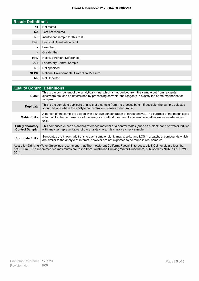
Not ReportedNR
National Environmental Protection MeasureNEPM
Not specifiedNS
Laboratory Control SampleLCS
Relative Percent DifferenceRPD
Greater than>
Less than<
Practical Quantitation LimitPQL
Insufficient sample for this testINS
Test not requiredNA
Not testedNT
Result Definitions
Australian Drinking Water Guidelines recommend that Thermotolerant Coliform, Faecal Enterococci, & E.Coli levels are less than1cfu/100mL. The recommended maximums are taken from "Australian Drinking Water Guidelines", published by NHMRC & ARMC2011.
Surrogates are known additions to each sample, blank, matrix spike and LCS in a batch, of compounds whichare similar to the analyte of interest, however are not expected to be found in real samples.
Surrogate Spike
This comprises either a standard reference material or a control matrix (such as a blank sand or water) fortifiedwith analytes representative of the analyte class. It is simply a check sample.
LCS (LaboratoryControl Sample)
A portion of the sample is spiked with a known concentration of target analyte. The purpose of the matrix spikeis to monitor the performance of the analytical method used and to determine whether matrix interferencesexist.
Matrix Spike
This is the complete duplicate analysis of a sample from the process batch. If possible, the sample selectedshould be one where the analyte concentration is easily measurable.
Duplicate
This is the component of the analytical signal which is not derived from the sample but from reagents,glassware etc, can be determined by processing solvents and reagents in exactly the same manner as forsamples.
Blank
Quality Control Definitions
Envirolab Reference: 173920
R00Revision No:
Page | 5 of 6
Client Reference: P1706047COC02V01
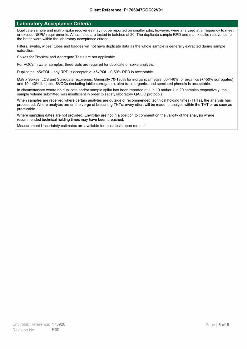
Measurement Uncertainty estimates are available for most tests upon request.
Where sampling dates are not provided, Envirolab are not in a position to comment on the validity of the analysis whererecommended technical holding times may have been breached.
When samples are received where certain analytes are outside of recommended technical holding times (THTs), the analysis hasproceeded. Where analytes are on the verge of breaching THTs, every effort will be made to analyse within the THT or as soon aspracticable.
In circumstances where no duplicate and/or sample spike has been reported at 1 in 10 and/or 1 in 20 samples respectively, thesample volume submitted was insufficient in order to satisfy laboratory QA/QC protocols.
Matrix Spikes, LCS and Surrogate recoveries: Generally 70-130% for inorganics/metals; 60-140% for organics (+/-50% surrogates)and 10-140% for labile SVOCs (including labile surrogates), ultra trace organics and speciated phenols is acceptable.
Duplicates: <5xPQL - any RPD is acceptable; >5xPQL - 0-50% RPD is acceptable.
For VOCs in water samples, three vials are required for duplicate or spike analysis.
Spikes for Physical and Aggregate Tests are not applicable.
Filters, swabs, wipes, tubes and badges will not have duplicate data as the whole sample is generally extracted during sampleextraction.
Duplicate sample and matrix spike recoveries may not be reported on smaller jobs, however, were analysed at a frequency to meetor exceed NEPM requirements. All samples are tested in batches of 20. The duplicate sample RPD and matrix spike recoveries forthe batch were within the laboratory acceptance criteria.
Laboratory Acceptance Criteria
Envirolab Reference: 173920
R00Revision No:
Page | 6 of 6
martens
Preliminary Salinity and Geotechnical Assessment:
95 Cudgegong Road, Rouse Hill, NSW.
P1706047JR02V01 – September 2017
Page 38
11 Attachment E – General Geotechnical Recommendations
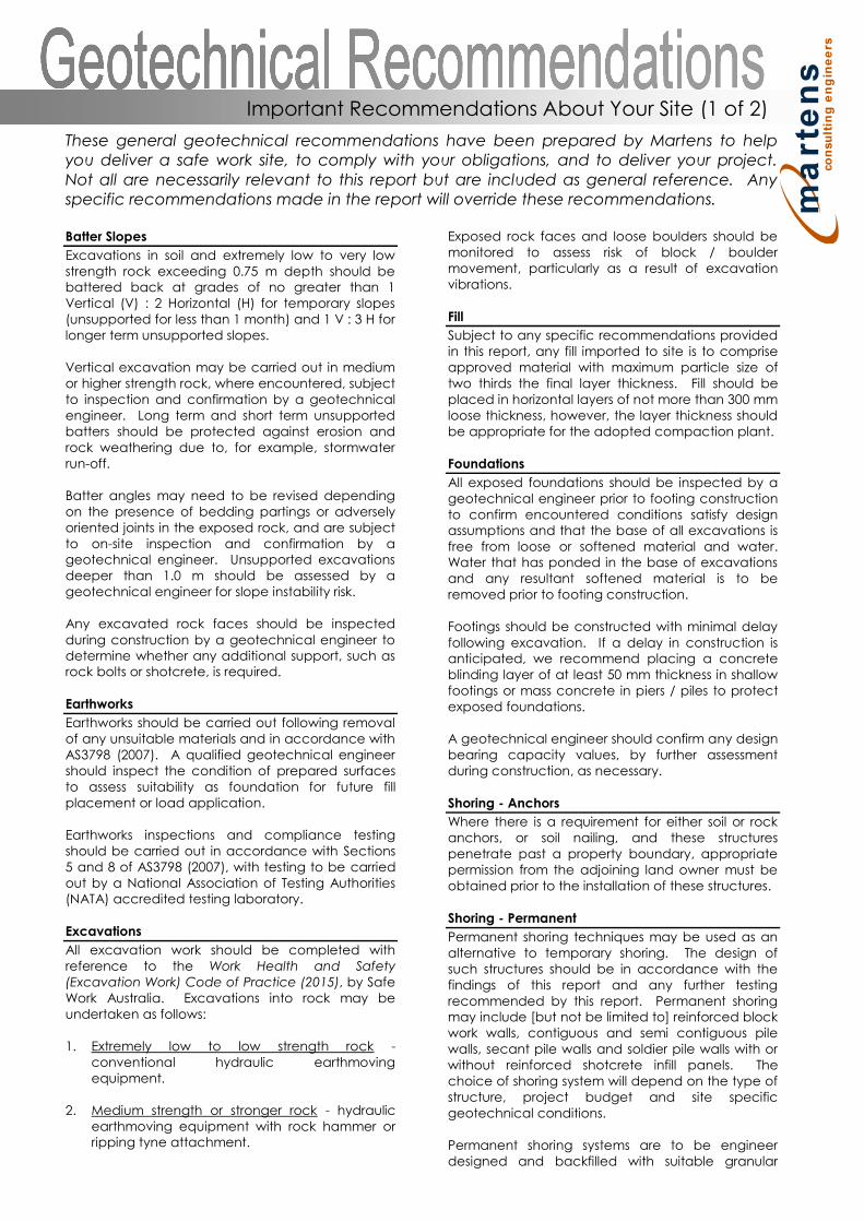
These general geotechnical recommendations have been prepared by Martens to helpyou deliver a safe work site, to comply with your obligations, and to deliver your project.Not all are necessarily relevant to this report but are included as general reference. Anyspecific recommendations made in the report will override these recommendations.
Batter Slopes
Excavations in soil and extremely low to very lowstrength rock exceeding 0.75 m depth should bebattered back at grades of no greater than 1Vertical (V) : 2 Horizontal (H) for temporary slopes(unsupported for less than 1 month) and 1 V : 3 H forlonger term unsupported slopes.
Vertical excavation may be carried out in mediumor higher strength rock, where encountered, subjectto inspection and confirmation by a geotechnicalengineer. Long term and short term unsupportedbatters should be protected against erosion androck weathering due to, for example, stormwaterrun-off.
Batter angles may need to be revised dependingon the presence of bedding partings or adverselyoriented joints in the exposed rock, and are subjectto on-site inspection and confirmation by ageotechnical engineer. Unsupported excavationsdeeper than 1.0 m should be assessed by ageotechnical engineer for slope instability risk.
Any excavated rock faces should be inspectedduring construction by a geotechnical engineer todetermine whether any additional support, such asrock bolts or shotcrete, is required.
Earthworks
Earthworks should be carried out following removalof any unsuitable materials and in accordance withAS3798 (2007). A qualified geotechnical engineershould inspect the condition of prepared surfacesto assess suitability as foundation for future fillplacement or load application.
Earthworks inspections and compliance testingshould be carried out in accordance with Sections5 and 8 of AS3798 (2007), with testing to be carriedout by a National Association of Testing Authorities(NATA) accredited testing laboratory.
Excavations
All excavation work should be completed withreference to the Work Health and Safety(Excavation Work) Code of Practice (2015), by SafeWork Australia. Excavations into rock may beundertaken as follows:
1. Extremely low to low strength rock -conventional hydraulic earthmovingequipment.
2. Medium strength or stronger rock - hydraulicearthmoving equipment with rock hammer orripping tyne attachment.
Exposed rock faces and loose boulders should bemonitored to assess risk of block / bouldermovement, particularly as a result of excavationvibrations.
Fill
Subject to any specific recommendations providedin this report, any fill imported to site is to compriseapproved material with maximum particle size oftwo thirds the final layer thickness. Fill should beplaced in horizontal layers of not more than 300 mmloose thickness, however, the layer thickness shouldbe appropriate for the adopted compaction plant.
Foundations
All exposed foundations should be inspected by ageotechnical engineer prior to footing constructionto confirm encountered conditions satisfy designassumptions and that the base of all excavations isfree from loose or softened material and water.Water that has ponded in the base of excavationsand any resultant softened material is to beremoved prior to footing construction.
Footings should be constructed with minimal delayfollowing excavation. If a delay in construction isanticipated, we recommend placing a concreteblinding layer of at least 50 mm thickness in shallowfootings or mass concrete in piers / piles to protectexposed foundations.
A geotechnical engineer should confirm any designbearing capacity values, by further assessmentduring construction, as necessary.
Shoring - Anchors
Where there is a requirement for either soil or rockanchors, or soil nailing, and these structurespenetrate past a property boundary, appropriatepermission from the adjoining land owner must beobtained prior to the installation of these structures.
Shoring - Permanent
Permanent shoring techniques may be used as analternative to temporary shoring. The design ofsuch structures should be in accordance with thefindings of this report and any further testingrecommended by this report. Permanent shoringmay include [but not be limited to] reinforced blockwork walls, contiguous and semi contiguous pilewalls, secant pile walls and soldier pile walls with orwithout reinforced shotcrete infill panels. Thechoice of shoring system will depend on the type ofstructure, project budget and site specificgeotechnical conditions.
Permanent shoring systems are to be engineerdesigned and backfilled with suitable granular
Important Recommendations About Your Site (1 of 2)

material and free-draining drainage material.Backfill should be placed in maximum 100 mm thicklayers compacted using a hand operatedcompactor. Care should be taken to ensureexcessive compaction stresses are not transferredto retaining walls.
Shoring design should consider any surchargeloading from sloping / raised ground behind shoringstructures, live loads, new structures, constructionequipment, backfill compaction and static waterpressures. All shoring systems shall be provided withadequate foundation designs.
Suitable drainage measures, such as geotextileenclosed 100 mm agricultural pipes embedded infree-draining gravel, should be included to redirectwater that may collect behind the shoring structureto a suitable discharge point.
Shoring - Temporary
In the absence of providing acceptableexcavation batters, excavations should besupported by suitably designed and installedtemporary shoring / retaining structures to limitlateral deflection of excavation faces andassociated ground surface settlements.
Soil Erosion Control
Removal of any soil overburden should beperformed in a manner that reduces the risk ofsedimentation occurring in any formal stormwaterdrainage system, on neighbouring land and inreceiving waters. Where possible, this may beachieved by one or more of the following means:
1. Maintain vegetation where possible2. Disturb minimal areas during excavation3. Revegetate disturbed areas if possible
All spoil on site should be properly controlled byerosion control measures to prevent transportationof sediments off-site. Appropriate soil erosion controlmethods in accordance with Landcom (2004) shallbe required.
Trafficability and Access
Consideration should be given to the impact of theproposed works and site subsurface conditions ontrafficability within the site e.g. wet clay soils willlead to poor trafficability by tyred plant or vehicles.
Where site access is likely to be affected by any siteworks, construction staging should be organisedsuch that any impacts on adequate access areminimised as best as possible.
Vibration Management
Where excavation is to be extended into mediumor higher strength rock, care will be required whenusing a rock hammer to limit potential structuraldistress from excavation-induced vibrations wherenearby structures may be affected by the works.
To limit vibrations, we recommend limiting rockhammer size and set frequency, and setting thehammer parallel to bedding planes and alongdefect planes, where possible, or as advised by ageotechnical engineer. We recommend limitingvibration peak particle velocities (PPV) caused byconstruction equipment or resulting fromexcavation at the site to 5 mm/s (AS 2187.2, 2006,Appendix J).
Waste Spoil and Water
Soil to be disposed off-site should be classified inaccordance with the relevant State Authorityguidelines and requirements.
Any collected waste stormwater or groundwatershould also be tested prior to discharge to ensurecontaminant levels (where applicable) areappropriate for the nominated discharge location.
MA can complete the necessary classification andtesting if required. Time allowance should be madefor such testing in the construction program.
Water Management - Groundwater
If the proposed works are likely to intersectephemeral or permanent groundwater levels, themanagement of any potential acid soil drainageshould be considered. If groundwater tables arelikely to be lowered, this should be further discussedwith the relevant State Government Agency.
Water Management Surface Water
All surface runoff should be diverted away fromexcavation areas during construction works andprevented from accumulating in areas surroundingany retaining structures, footings or the base ofexcavations.
Any collected surface water should be dischargedinto a suitable Council approved drainage systemand not adversely impact downslope surface andsubsurface conditions.
All site discharges should be passed through a filtermaterial prior to release. Sump and pump methodswill generally be suitable for collection and removalof accumulated surface water within anyexcavations.
Contingency Plan
In the event that proposed development workscause an adverse impact on geotechnical hazards,overall site stability or adjacent properties, thefollowing actions are to be undertaken:
1. Works shall cease immediately.2. The nature of the impact shall be documented
and the reason(s) for the adverse impactinvestigated.
3. A qualified geotechnical engineer should beconsulted to provide further advice in relationto the issue.
Important Recommendations About Your Site (2 of 2)
martens
Preliminary Salinity and Geotechnical Assessment:
95 Cudgegong Road, Rouse Hill, NSW.
P1706047JR02V01 – September 2017
Page 41
12 Attachment F – Notes About This Report

These notes have been prepared by Martens to help you interpret and understand thelimitations of your report. Not all are necessarily relevant to all reports but are included asgeneral reference.
Engineering Reports - Limitations
The recommendations presented in this report arebased on limited investigations and include specificissues to be addressed during various phases of theproject. If the recommendations presented in thisreport are not implemented in full, the generalrecommendations may become inapplicable andMartens & Associates accept no responsibilitywhatsoever for the performance of the worksundertaken.
Occasionally, sub-surface conditions between andbelow the completed boreholes or other tests maybe found to be different (or may be interpreted tobe different) from those expected. Variation canalso occur with groundwater conditions, especiallyafter climatic changes. If such differences appearto exist, we recommend that you immediatelycontact Martens & Associates.
Relative ground surface levels at borehole locationsmay not be accurate and should be verified by on-site survey.
Engineering Reports Project Specific Criteria
Engineering reports are prepared by qualifiedpersonnel. They are based on informationobtained, on current engineering standards ofinterpretation and analysis, and on the basis of yourunique project specific requirements as understoodby Martens. Project criteria typically include thegeneral nature of the project; its size andconfiguration; the location of any structures on thesite; other site improvements; the presence ofunderground utilities; and the additional riskimposed by scope-of-service limitations imposed bythe Client.
Where the report has been prepared for a specificdesign proposal (e.g. a three storey building), theinformation and interpretation may not be relevantif the design proposal is changed (e.g. to a twentystorey building). Your report should not be reliedupon, if there are changes to the project, withoutfirst asking Martens to assess how factors, whichchanged subsequent to the date of the report,
not accept responsibility for problems that mayoccur due to design changes, if not consulted.
Engineering Reports Recommendations
Your report is based on the assumption that siteconditions, as may be revealed through selectivepoint sampling, are indicative of actual conditionsthroughout an area. This assumption often cannotbe substantiated until project implementation hascommenced. Therefore your site investigationreport recommendations should only be regardedas preliminary.
Only Martens, who prepared the report, are fullyfamiliar with the background information needed to
recommendations are valid and whether or notchanges should be considered as the projectdevelops. If another party undertakes theimplementation of the recommendations of thisreport, there is a risk that the report will bemisinterpreted and Martens cannot be heldresponsible for such misinterpretation.
Engineering Reports Use for Tendering Purposes
Where information obtained from investigations isprovided for tendering purposes, Martensrecommend that all information, including thewritten report and discussion, be made available. Incircumstances where the discussion or commentssection is not relevant to the contractual situation, itmay be appropriate to prepare a specially editeddocument.
Martens would be pleased to assist in this regardand/or to make additional report copies availablefor contract purposes at a nominal charge.
Engineering Reports Data
The report as a whole presents the findings of a siteassessment and should not be copied in part oraltered in any way.
Logs, figures, drawings etc are customarily includedin a Martens report and are developed by scientists,engineers or geologists based on their interpretationof field logs (assembled by field personnel), desktopstudies and laboratory evaluation of field samples.These data should not under any circumstances beredrawn for inclusion in other documents orseparated from the report in any way.
Engineering Reports Other Projects
To avoid misuse of the information contained inyour report it is recommended that you confer withMartens before passing your report on to anotherparty who may not be familiar with the backgroundand purpose of the report. Your report should notbe applied to any project other than that originallyspecified at the time the report was issued.
Subsurface Conditions - General
Every care is taken with the report in relation tointerpretation of subsurface conditions, discussion ofgeotechnical aspects, relevant standards andrecommendations or suggestions for design andconstruction. However, the Company cannotalways anticipate or assume responsibility for:
o Unexpected variations in ground conditions -the potential will depend partly on test point
Important Information About Your Report (1 of 2)
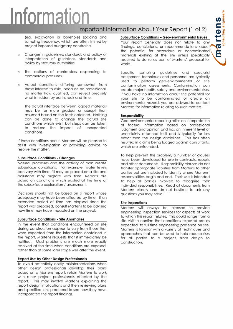
(eg. excavation or borehole) spacing andsampling frequency, which are often limited byproject imposed budgetary constraints.
o Changes in guidelines, standards and policy orinterpretation of guidelines, standards andpolicy by statutory authorities.
o The actions of contractors responding tocommercial pressures.
o Actual conditions differing somewhat fromthose inferred to exist, because no professional,no matter how qualified, can reveal preciselywhat is hidden by earth, rock and time.
The actual interface between logged materialsmay be far more gradual or abrupt thanassumed based on the facts obtained. Nothingcan be done to change the actual siteconditions which exist, but steps can be takento reduce the impact of unexpectedconditions.
If these conditions occur, Martens will be pleased toassist with investigation or providing advice toresolve the matter.
Subsurface Conditions - Changes
Natural processes and the activity of man createsubsurface conditions. For example, water levelscan vary with time, fill may be placed on a site andpollutants may migrate with time. Reports arebased on conditions which existed at the time ofthe subsurface exploration / assessment.
Decisions should not be based on a report whoseadequacy may have been affected by time. If anextended period of time has elapsed since thereport was prepared, consult Martens to be advisedhow time may have impacted on the project.
Subsurface Conditions - Site Anomalies
In the event that conditions encountered on siteduring construction appear to vary from those thatwere expected from the information contained inthe report, Martens requests that it immediately benotified. Most problems are much more readilyresolved at the time when conditions are exposed,rather than at some later stage well after the event.
Report Use by Other Design Professionals
To avoid potentially costly misinterpretations whenother design professionals develop their plansbased on a Martens report, retain Martens to workwith other project professionals affected by thereport. This may involve Martens explaining thereport design implications and then reviewing plansand specifications produced to see how they haveincorporated the report findings.
Subsurface Conditions Geo-environmental Issues
Your report generally does not relate to anyfindings, conclusions, or recommendations aboutthe potential for hazardous or contaminatedmaterials existing at the site unless specificallyrequired to do so as part of proposal forworks.
Specific sampling guidelines and specialistequipment, techniques and personnel are typicallyused to perform geo-environmental or sitecontamination assessments. Contamination cancreate major health, safety and environmental risks.If you have no information about the potential foryour site to be contaminated or create anenvironmental hazard, you are advised to contactMartens for information relating to such matters.
Responsibility
Geo-environmental reporting relies on interpretationof factual information based on professionaljudgment and opinion and has an inherent level ofuncertainty attached to it and is typically far lessexact than the design disciplines. This has oftenresulted in claims being lodged against consultants,which are unfounded.
To help prevent this problem, a number of clauseshave been developed for use in contracts, reportsand other documents. Responsibility clauses do nottransfer appropriate liabilities from Martens to other
responsibilities begin and end. Their use is intendedto help all parties involved to recognise theirindividual responsibilities. Read all documents fromMartens closely and do not hesitate to ask anyquestions you may have.
Site Inspections
Martens will always be pleased to provideengineering inspection services for aspects of workto which this report relates. This could range from asite visit to confirm that conditions exposed are asexpected, to full time engineering presence on site.Martens is familiar with a variety of techniques andapproaches that can be used to help reduce risksfor all parties to a project, from design toconstruction.
Important Information About Your Report (1 of 2)

Definitions
In engineering terms, soil includes every type ofuncemented or partially cemented inorganic or organicmaterial found in the ground. In practice, if the materialdoes not exhibit any visible rock properties and can beremoulded or disintegrated by hand in its field condition orin water it is described as a soil. Other materials aredescribed using rock description terms.
The methods of description and classification of soils androcks used in this report are typically based on AustralianStandard 1726 and the Unified Soil Classification System(USCS) refer Soil Data Explanation of Terms (2 of 3). Ingeneral, descriptions cover the following properties -strength or density, colour, structure, soil or rock type andinclusions.
Particle Size
Soil types are described according to the predominatingparticle size, qualified by the grading of other particlespresent (e.g. sandy CLAY). Unless otherwise stated,particle size is described in accordance with the followingtable.
Division Subdivision Size (mm)
BOULDERS >200
COBBLES 63 to 200
GRAVEL
Coarse 20 to 63
Medium 6 to 20
Fine 2.36 to 6
SAND
Coarse 0.6 to 2.36
Medium 0.2 to 0.6
Fine 0.075 to 0.2
SILT 0.002 to 0.075
CLAY < 0.002
Plasticity Properties
Plasticity properties of cohesive soils can be assessed inthe field by tactile properties or by laboratory procedures.
Moisture Condition
Dry Looks and feels dry. Cohesive and cemented soils arehard, friable or powdery. Uncemented granular soils runfreely through hands.
Moist Soil feels cool and damp and is darkened in colour.Cohesive soils can be moulded. Granular soils tend tocohere.
Wet As for moist but with free water forming on hands whenhandled.
Consistency of Cohesive Soils
Cohesive soils refer to predominantly clay materials.
TermCu
(kPa)Approx.
Field Guide
VerySoft
<12 2
A finger can be pushed well intothe soil with little effort. Sampleextrudes between fingers when
squeezed in fist.
Soft 12 - 25 2 4A finger can be pushed into thesoil to about 25mm depth. Easily
moulded in fingers.
Firm 25 - 50 4 8
The soil can be indented about5mm with the thumb, but not
penetrated. Can be moulded bystrong pressure in the figures.
Stiff 50 - 100 8 15
The surface of the soil can beindented with the thumb, but notpenetrated. Cannot be moulded
by fingers.
VeryStiff
100 - 200 15 30
The surface of the soil can bemarked, but not indented withthumb pressure. Difficult to cut
with a knife. Thumbnail canreadily indent.
Hard > 200 > 30
The surface of the soil can bemarked only with the thumbnail.
Brittle. Tends to break intofragments.
Friable - -Crumbles or powders when
scraped by thumbnail.
Density of Granular Soils
Non-cohesive soils are classified on the basis of relativedensity, generally from standard penetration test (SPT) orDutch cone penetrometer test (CPT) results as below:
RelativeDensity
%*
(blows/300mm)
CPT ConeValue
(qc MPa)
Very loose < 15 < 5 < 2
Loose 15 - 35 5 - 10 2 - 5
Medium dense 35 - 65 10 - 30 5 - 15
Dense 65 - 85 30 - 50 15 - 25
Very dense > 85 > 50 > 25
* Values may be subject to corrections for overburden pressures and
equipment type.
Minor Components
Minor components in soils may be present and readilydetectable, but have little bearing on generalgeotechnical classification. Terms include:
0BTerm AssessmentProportion of
Minor component In:
Trace of
Presence justdetectable by feel or
eye. Soil properties littleor no different to
general properties ofprimary component.
Coarse grained soils:< 5 %
Fine grained soils:< 15 %
With some
Presence easilydetectable by feel or
eye. Soil properties littledifferent to general
properties of primarycomponent.
Coarse grained soils:5 12 %
Fine grained soils:15 30 %
Explanation of Terms (1 of 3)
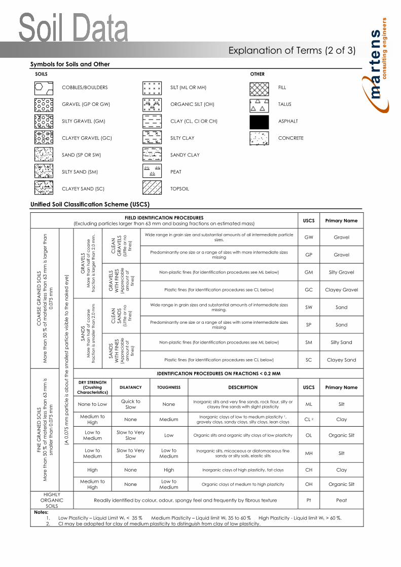
Symbols for Soils and Other
SOILS OTHER
COBBLES/BOULDERS SILT (ML OR MH) FILL
GRAVEL (GP OR GW) ORGANIC SILT (OH) TALUS
SILTY GRAVEL (GM) CLAY (CL, CI OR CH) ASPHALT
CLAYEY GRAVEL (GC) SILTY CLAY CONCRETE
SAND (SP OR SW) SANDY CLAY
SILTY SAND (SM) PEAT
CLAYEY SAND (SC) TOPSOIL
Unified Soil Classification Scheme (USCS)
FIELD IDENTIFICATION PROCEDURES(Excluding particles larger than 63 mm and basing fractions on estimated mass)
USCS Primary Name
CO
AR
SEG
RA
INED
SO
ILS
Mo
reth
an
50
%o
fm
ate
riall
ess
tha
n63
mm
isla
rge
rth
an
0.0
75
mm
(A0.0
75
mm
pa
rtic
leis
ab
ou
tth
esm
alle
stp
art
icle
vis
ible
toth
en
ake
de
ye
)
GR
AV
ELS
Mo
reth
an
ha
lfo
fc
oa
rse
fra
ctio
nis
larg
er
tha
n2
.0m
m.
CLE
AN
GR
AV
ELS
(Little
or
no
fin
es)
Wide range in grain size and substantial amounts of all intermediate particlesizes.
GW Gravel
Predominantly one size or a range of sizes with more intermediate sizesmissing
GP Gravel
GR
AV
ELS
WIT
HFI
NES
(Ap
pre
cia
ble
am
ou
nt
of
fin
es)
Non-plastic fines (for identification procedures see ML below) GM Silty Gravel
Plastic fines (for identification procedures see CL below) GC Clayey Gravel
SAN
DS
Mo
reth
an
ha
lfo
fc
oa
rse
fra
ctio
nis
sma
ller
tha
n2
.0m
m
CLE
AN
SAN
DS
(Little
or
no
fin
es)
Wide range in grain sizes and substantial amounts of intermediate sizesmissing.
SW Sand
Predominantly one size or a range of sizes with some intermediate sizesmissing
SP Sand
SA
ND
S
WIT
HFI
NES
(Ap
pre
cia
ble
am
ou
nt
of
fin
es)
Non-plastic fines (for identification procedures see ML below) SM Silty Sand
Plastic fines (for identification procedures see CL below) SC Clayey Sand
FIN
EG
RA
INED
SOIL
S
Mo
reth
an
50
%o
fm
ate
rialle
ssth
an
63
mm
is
sma
ller
tha
n0.0
75
mm
1BIDENTIFICATION PROCEDURES ON FRACTIONS < 0.2MM
DRY STRENGTH(Crushing
Characteristics)DILATANCY TOUGHNESS DESCRIPTION USCS Primary Name
None to LowQuick to
SlowNone
Inorganic silts and very fine sands, rock flour, silty orclayey fine sands with slight plasticity
ML Silt
Medium toHigh
None MediumInorganic clays of low to medium plasticity 1,
gravely clays, sandy clays, silty clays, lean claysCL 2 Clay
Low toMedium
Slow to VerySlow
Low Organic slits and organic silty clays of low plasticity OL Organic Silt
Low toMedium
Slow to VerySlow
Low toMedium
Inorganic silts, micaceous or diatomaceous finesandy or silty soils, elastic silts
MH Silt
High None High Inorganic clays of high plasticity, fat clays CH Clay
Medium toHigh
NoneLow to
MediumOrganic clays of medium to high plasticity OH Organic Silt
HIGHLYORGANIC
SOILSReadily identified by colour, odour, spongy feel and frequently by fibrous texture Pt Peat
Notes:1. Low Plasticity Liquid Limit WL < 35 % Medium Plasticity Liquid limit WL 35 to 60 % High Plasticity - Liquid limit WL > 60 %.2. CI may be adopted for clay of medium plasticity to distinguish from clay of low plasticity.
Explanation of Terms (2 of 3)

Soil Agricultural Classification Scheme
In some situations, such as where soils are to be used for effluent disposal purposes, soils are often more appropriately classifiedin terms of traditional agricultural classification schemes. Where a Martens report provides agricultural classifications, these areundertaken in accordance with descriptions by Northcote, K.H. (1979) The factual key for the recognition of Australian Soils,Rellim Technical Publications, NSW, p 26 - 28.
Symbol Field Texture Grade Behaviour of moist bolus Ribbon lengthClay content
(%)
S SandCoherence nil to very slight; cannot be moulded; single grains
adhere to fingers0 mm < 5
LS Loamy sand Slight coherence; discolours fingers with dark organic stain 6.35 mm 5
CLS Clayey sandSlight coherence; sticky when wet; many sand grains stick to
fingers; discolours fingers with clay stain6.35mm - 1.3cm 5 - 10
SL Sandy loamBolus just coherent but very sandy to touch; dominant sand
grains are of medium size and are readily visible1.3 - 2.5 10 - 15
FSL Fine sandy loam Bolus coherent; fine sand can be felt and heard 1.3 - 2.5 10 - 20
SCL- Light sandy clay loamBolus strongly coherent but sandy to touch, sand grains
dominantly medium size and easily visible2.0 15 - 20
L LoamBolus coherent and rather spongy; smooth feel when
manipulated but no obvious sandiness or silkiness; may besomewhat greasy to the touch if much organic matter present
2.5 25
Lfsy Loam, fine sandyBolus coherent and slightly spongy; fine sand can be felt and
heard when manipulated2.5 25
SiL Silt loam Coherent bolus, very smooth to silky when manipulated 2.5 25 + > 25 silt
SCL Sandy clay loamStrongly coherent bolus sandy to touch; medium size sand
grains visible in a finer matrix2.5 - 3.8 20 - 30
CL Clay loam Coherent plastic bolus; smooth to manipulate 3.8 - 5.0 30 - 35
SiCL Silty clay loam Coherent smooth bolus; plastic and silky to touch 3.8 - 5.0 30- 35 + > 25 silt
FSCL Fine sandy clay loam Coherent bolus; fine sand can be felt and heard 3.8 - 5.0 30 - 35
SC Sandy clayPlastic bolus; fine to medium sized sands can be seen, felt or
heard in a clayey matrix5.0 - 7.5 35 - 40
SiC Silty clay Plastic bolus; smooth and silky 5.0 - 7.5 35 - 40 + > 25 silt
LC Light clay Plastic bolus; smooth to touch; slight resistance to shearing 5.0 - 7.5 35 - 40
LMC Light medium clayPlastic bolus; smooth to touch, slightly greater resistance to
shearing than LC7.5 40 - 45
MC Medium claySmooth plastic bolus, handles like plasticine and can be
moulded into rods without fracture, some resistance to shearing> 7.5 45 - 55
HC Heavy claySmooth plastic bolus; handles like stiff plasticine; can be
moulded into rods without fracture; firm resistance to shearing> 7.5 > 50
Explanation of Terms (3 of 3)
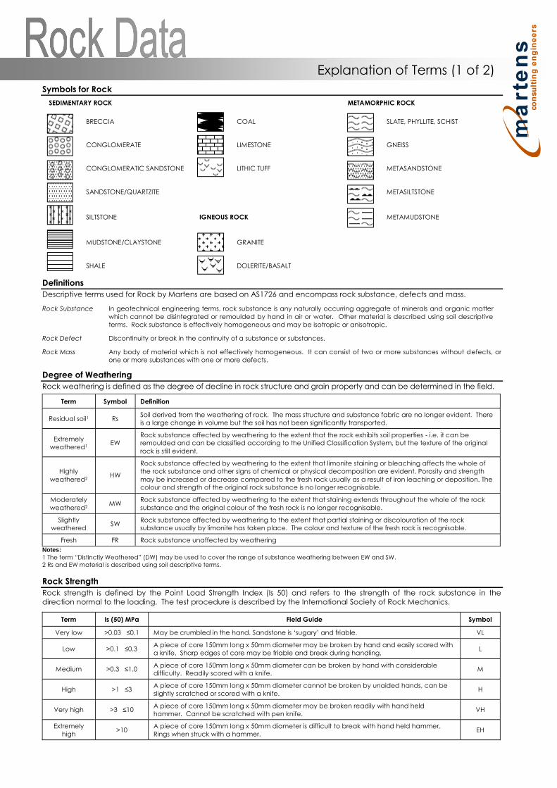
Symbols for Rock
SEDIMENTARY ROCK METAMORPHIC ROCK
BRECCIA COAL SLATE, PHYLLITE, SCHIST
CONGLOMERATE LIMESTONE GNEISS
CONGLOMERATIC SANDSTONE LITHIC TUFF METASANDSTONE
SANDSTONE/QUARTZITE METASILTSTONE
SILTSTONE IGNEOUS ROCK METAMUDSTONE
MUDSTONE/CLAYSTONE GRANITE
SHALE DOLERITE/BASALT
Definitions
Descriptive terms used for Rock by Martens are based on AS1726 and encompass rock substance, defects and mass.
Rock Substance In geotechnical engineering terms, rock substance is any naturally occurring aggregate of minerals and organic matterwhich cannot be disintegrated or remoulded by hand in air or water. Other material is described using soil descriptiveterms. Rock substance is effectively homogeneous and may be isotropic or anisotropic.
Rock Defect Discontinuity or break in the continuity of a substance or substances.
Rock Mass Any body of material which is not effectively homogeneous. It can consist of two or more substances without defects, orone or more substances with one or more defects.
Degree of Weathering
Rock weathering is defined as the degree of decline in rock structure and grain property and can be determined in the field.
Term Symbol Definition
Residual soil1 RsSoil derived from the weathering of rock. The mass structure and substance fabric are no longer evident. Thereis a large change in volume but the soil has not been significantly transported.
Extremelyweathered1
EWRock substance affected by weathering to the extent that the rock exhibits soil properties - i.e. it can beremoulded and can be classified according to the Unified Classification System, but the texture of the originalrock is still evident.
Highlyweathered2
HW
Rock substance affected by weathering to the extent that limonite staining or bleaching affects the whole ofthe rock substance and other signs of chemical or physical decomposition are evident. Porosity and strengthmay be increased or decrease compared to the fresh rock usually as a result of iron leaching or deposition. Thecolour and strength of the original rock substance is no longer recognisable.
Moderatelyweathered2
MWRock substance affected by weathering to the extent that staining extends throughout the whole of the rocksubstance and the original colour of the fresh rock is no longer recognisable.
Slightlyweathered
SWRock substance affected by weathering to the extent that partial staining or discolouration of the rocksubstance usually by limonite has taken place. The colour and texture of the fresh rock is recognisable.
Fresh FR Rock substance unaffected by weathering
Notes:
2 Rs and EW material is described using soil descriptive terms.
Rock Strength
Rock strength is defined by the Point Load Strength Index (Is 50) and refers to the strength of the rock substance in thedirection normal to the loading. The test procedure is described by the International Society of Rock Mechanics.
Term Is (50)MPa Field Guide Symbol
Very low 0.1 May be VL
Low >0.1 0.3A piece of core 150mm long x 50mm diameter may be broken by hand and easily scored witha knife. Sharp edges of core may be friable and break during handling.
L
Medium >0.3A piece of core 150mm long x 50mm diameter can be broken by hand with considerabledifficulty. Readily scored with a knife.
M
High 3A piece of core 150mm long x 50mm diameter cannot be broken by unaided hands, can beslightly scratched or scored with a knife.
H
Very highA piece of core 150mm long x 50mm diameter may be broken readily with hand heldhammer. Cannot be scratched with pen knife.
VH
Extremelyhigh
>10A piece of core 150mm long x 50mm diameter is difficult to break with hand held hammer.Rings when struck with a hammer.
EH
Explanation of Terms (1 of 2)
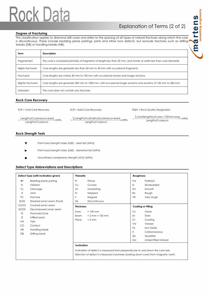
Degree of Fracturing
This classification applies to diamond drill cores and refers to the spacing of all types of natural fractures along which the coreis discontinuous. These include bedding plane partings, joints and other rock defects, but exclude fractures such as drillingbreaks (DB) or handling breaks (HB).
Term Description
Fragmented The core is comprised primarily of fragments of length less than 20 mm, and mostly of width less than core diameter.
Highly fractured Core lengths are generally less than 20 mm to 40 mm with occasional fragments.
Fractured Core lengths are mainly 30 mm to 100 mm with occasional shorter and longer sections.
Slightly fractured Core lengths are generally 300 mm to 1000 mm, with occasional longer sections and sections of 100 mm to 300 mm.
Unbroken The core does not contain any fractures.
Rock Core Recovery
TCR = Total Core Recovery SCR = Solid Core Recovery RQD = Rock Quality Designation
Rock Strength Tests
Point load strength Index (Is50) - axial test (MPa)
Point load strength Index (Is50) - diametral test (MPa)
Unconfined compressive strength (UCS) (MPa)
Defect Type Abbreviations and Descriptions
2BDefect Type (with inclination given) 3BPlanarity 4BRoughness
BP
FL
CL
JT
FC
SZ/SS
CZ/CS
DZ/DS
FZ
IS
VN
CO
HB
DB
Bedding plane parting
Foliation
Cleavage
Joint
Fracture
Sheared zone/ seam (Fault)
Crushed zone/ seam
Decomposed zone/ seam
Fractured Zone
Infilled seam
Vein
Contact
Handling break
Drilling break
Pl
Cu
Un
St
Ir
Dis
Planar
Curved
Undulating
Stepped
Irregular
Discontinuous
Pol
Sl
Sm
Ro
VR
Polished
Slickensided
Smooth
Rough
Very rough
Thickness 5BCoating or Filling
Zone
Seam
Plane
> 100 mm
> 2 mm < 100 mm
< 2 mm
Cn
Sn
Ct
Vnr
Fe
X
Qz
MU
Clean
Stain
Coating
Veneer
Iron Oxide
Carbonaceous
Quartzite
Unidentified mineral
6BInclination
Inclination of defect is measured from perpendicular to and down the core axis.
Direction of defect is measured clockwise (looking down core) from magnetic north.
Explanation of Terms (2 of 2)
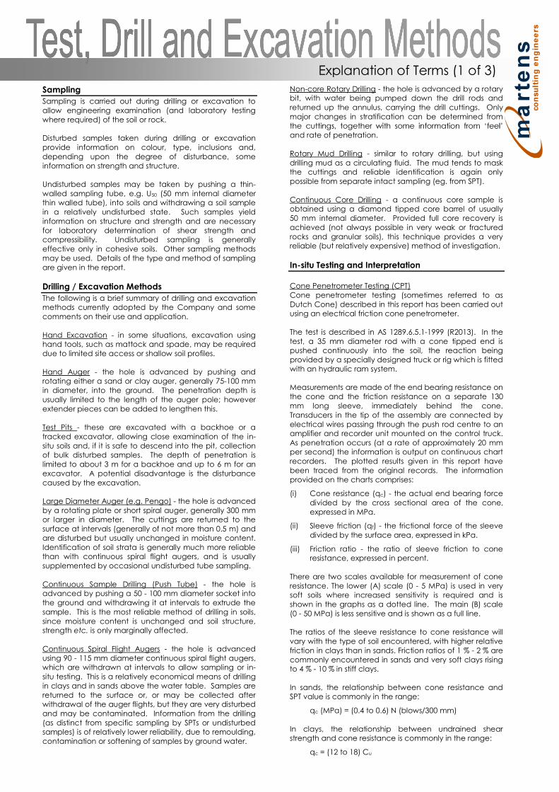
Sampling
Sampling is carried out during drilling or excavation toallow engineering examination (and laboratory testingwhere required) of the soil or rock.
Disturbed samples taken during drilling or excavationprovide information on colour, type, inclusions and,depending upon the degree of disturbance, someinformation on strength and structure.
Undisturbed samples may be taken by pushing a thin-walled sampling tube, e.g. U50 (50 mm internal diameterthin walled tube), into soils and withdrawing a soil samplein a relatively undisturbed state. Such samples yieldinformation on structure and strength and are necessaryfor laboratory determination of shear strength andcompressibility. Undisturbed sampling is generallyeffective only in cohesive soils. Other sampling methodsmay be used. Details of the type and method of samplingare given in the report.
Drilling /Excavation Methods
The following is a brief summary of drilling and excavationmethods currently adopted by the Company and somecomments on their use and application.
Hand Excavation - in some situations, excavation usinghand tools, such as mattock and spade, may be requireddue to limited site access or shallow soil profiles.
Hand Auger - the hole is advanced by pushing androtating either a sand or clay auger, generally 75-100 mmin diameter, into the ground. The penetration depth isusually limited to the length of the auger pole; howeverextender pieces can be added to lengthen this.
Test Pits - these are excavated with a backhoe or atracked excavator, allowing close examination of the in-situ soils and, if it is safe to descend into the pit, collectionof bulk disturbed samples. The depth of penetration islimited to about 3 m for a backhoe and up to 6 m for anexcavator. A potential disadvantage is the disturbancecaused by the excavation.
Large Diameter Auger (e.g. Pengo) - the hole is advancedby a rotating plate or short spiral auger, generally 300 mmor larger in diameter. The cuttings are returned to thesurface at intervals (generally of not more than 0.5 m) andare disturbed but usually unchanged in moisture content.Identification of soil strata is generally much more reliablethan with continuous spiral flight augers, and is usuallysupplemented by occasional undisturbed tube sampling.
Continuous Sample Drilling (Push Tube) - the hole isadvanced by pushing a 50 - 100 mm diameter socket intothe ground and withdrawing it at intervals to extrude thesample. This is the most reliable method of drilling in soils,since moisture content is unchanged and soil structure,strength etc. is only marginally affected.
Continuous Spiral Flight Augers - the hole is advancedusing 90 - 115 mm diameter continuous spiral flight augers,which are withdrawn at intervals to allow sampling or in-situ testing. This is a relatively economical means of drillingin clays and in sands above the water table. Samples arereturned to the surface or, or may be collected afterwithdrawal of the auger flights, but they are very disturbedand may be contaminated. Information from the drilling(as distinct from specific sampling by SPTs or undisturbedsamples) is of relatively lower reliability, due to remoulding,contamination or softening of samples by ground water.
Non-core Rotary Drilling - the hole is advanced by a rotarybit, with water being pumped down the drill rods andreturned up the annulus, carrying the drill cuttings. Onlymajor changes in stratification can be determined from
and rate of penetration.
Rotary Mud Drilling - similar to rotary drilling, but usingdrilling mud as a circulating fluid. The mud tends to maskthe cuttings and reliable identification is again onlypossible from separate intact sampling (eg. from SPT).
Continuous Core Drilling - a continuous core sample isobtained using a diamond tipped core barrel of usually50 mm internal diameter. Provided full core recovery isachieved (not always possible in very weak or fracturedrocks and granular soils), this technique provides a veryreliable (but relatively expensive) method of investigation.
In-situ Testing and Interpretation
Cone Penetrometer Testing (CPT)Cone penetrometer testing (sometimes referred to asDutch Cone) described in this report has been carried outusing an electrical friction cone penetrometer.
The test is described in AS 1289.6.5.1-1999 (R2013). In thetest, a 35 mm diameter rod with a cone tipped end ispushed continuously into the soil, the reaction beingprovided by a specially designed truck or rig which is fittedwith an hydraulic ram system.
Measurements are made of the end bearing resistance onthe cone and the friction resistance on a separate 130mm long sleeve, immediately behind the cone.Transducers in the tip of the assembly are connected byelectrical wires passing through the push rod centre to anamplifier and recorder unit mounted on the control truck.As penetration occurs (at a rate of approximately 20 mmper second) the information is output on continuous chartrecorders. The plotted results given in this report havebeen traced from the original records. The informationprovided on the charts comprises:
(i) Cone resistance (qc) - the actual end bearing forcedivided by the cross sectional area of the cone,expressed in MPa.
(ii) Sleeve friction (qf) - the frictional force of the sleevedivided by the surface area, expressed in kPa.
(iii) Friction ratio - the ratio of sleeve friction to coneresistance, expressed in percent.
There are two scales available for measurement of coneresistance. The lower (A) scale (0 - 5 MPa) is used in verysoft soils where increased sensitivity is required and isshown in the graphs as a dotted line. The main (B) scale(0 - 50 MPa) is less sensitive and is shown as a full line.
The ratios of the sleeve resistance to cone resistance willvary with the type of soil encountered, with higher relativefriction in clays than in sands. Friction ratios of 1 % - 2 % arecommonly encountered in sands and very soft clays risingto 4 % - 10 % in stiff clays.
In sands, the relationship between cone resistance andSPT value is commonly in the range:
qc (MPa) = (0.4 to 0.6) N (blows/300 mm)
In clays, the relationship between undrained shearstrength and cone resistance is commonly in the range:
qc = (12 to 18) Cu
Explanation of Terms (1 of 3)
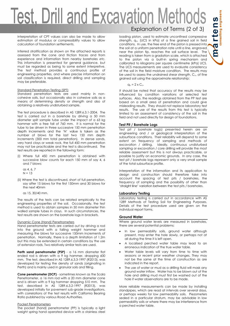
Interpretation of CPT values can also be made to allowestimation of modulus or compressibility values to allowcalculation of foundation settlements.
Inferred stratification as shown on the attached reports isassessed from the cone and friction traces and fromexperience and information from nearby boreholes etc.This information is presented for general guidance, butmust be regarded as being to some extent interpretive.The test method provides a continuous profile ofengineering properties, and where precise information onsoil classification is required, direct drilling and samplingmay be preferable.
Standard Penetration Testing (SPT)Standard penetration tests are used mainly in non-cohesive soils, but occasionally also in cohesive soils as ameans of determining density or strength and also ofobtaining a relatively undisturbed sample.
The test procedure is described in AS 1289.6.3.1-2004. Thetest is carried out in a borehole by driving a 50 mmdiameter split sample tube under the impact of a 63 kghammer with a free fall of 760 mm. It is normal for thetube to be driven in three successive 150 mm penetration
number of blows for the last two 150 mm depthincrements (300 mm total penetration). In dense sands,very hard clays or weak rock, the full 450 mm penetrationmay not be practicable and the test is discontinued. Thetest results are reported in the following form:
(i) Where full 450 mm penetration is obtained withsuccessive blow counts for each 150 mm of say 4, 6and 7 blows:
as 4, 6, 7N = 13
(ii) Where the test is discontinued, short of full penetration,say after 15 blows for the first 150mm and 30 blows forthe next 40mm
as 15, 30/40 mm.
The results of the tests can be related empirically to theengineering properties of the soil. Occasionally, the testmethod is used to obtain samples in 50 mm diameter thinwalled sample tubes in clays. In such circumstances, thetest results are shown on the borehole logs in brackets.
Dynamic Cone (Hand) PenetrometersHand penetrometer tests are carried out by driving a rodinto the ground with a falling weight hammer andmeasuring the blows for successive 150mm increments ofpenetration. Normally, there is a depth limitation of 1.2mbut this may be extended in certain conditions by the useof extension rods. Two relatively similar tests are used.
Perth sand penetrometer (PSP) - a 16 mm diameter flatended rod is driven with a 9 kg hammer, dropping 600mm. The test, described in AS 1289.6.3.3-1997 (R2013), wasdeveloped for testing the density of sands (originating inPerth) and is mainly used in granular soils and filling.
Cone penetrometer (DCP)- sometimes known as the ScalaPenetrometer, a 16 mm rod with a 20 mm diameter coneend is driven with a 9 kg hammer dropping 510 mm. Thetest, described in AS 1289.6.3.2-1997 (R2013), wasdeveloped initially for pavement sub-grade investigations,with correlations of the test results with California BearingRatio published by various Road Authorities.
Pocket PenetrometersThe pocket (hand) penetrometer (PP) is typically a lightweight spring hand operated device with a stainless steel
loading piston, used to estimate unconfined compressivestrength, qu, (UCS in kPa) of a fine grained soil in fieldconditions. In use, the free end of the piston is pressed intothe soil at a uniform penetration rate until a line, engravednear the piston tip, reaches the soil surface level. Thereading is taken from a gradation scale, which is attachedto the piston via a built-in spring mechanism andcalibrated to kilograms per square centimetre (kPa) UCS.The UCS measurements are used to evaluate consistencyof the soil in the field moisture condition. The results maybe used to assess the undrained shear strength, Cu, of finegrained soil using the approximate relationship:
qu = 2 x Cu.
It should be noted that accuracy of the results may beinfluenced by condition variations at selected testsurfaces. Also, the readings obtained from the PP test arebased on a small area of penetration and could givemisleading results. They should not replace laboratory testresults. The use of the results from this test is typicallylimited to an assessment of consistency of the soil in thefield and not used directly for design of foundations.
Test Pit /Borehole Logs
Test pit / borehole log(s) presented herein are anengineering and / or geological interpretation of thesubsurface conditions. Their reliability will depend to someextent on frequency of sampling and methods ofexcavation / drilling. Ideally, continuous undisturbedsampling or excavation / core drilling will provide the mostreliable assessment but this is not always practicable, orpossible to justify on economic grounds. In any case, thetest pit / borehole logs represent only a very small sampleof the total subsurface profile.
Interpretation of the information and its application todesign and construction should therefore take intoaccount the spacing of test pits / boreholes, thefrequency of sampling and the possibility of other than
test pits / boreholes.
Laboratory Testing
Laboratory testing is carried out in accordance with AS1289 Methods of Testing Soil for Engineering Purposes.Details of the test procedure used are given on theindividual report forms.
Ground Water
Where ground water levels are measured in boreholes,there are several potential problems:
In low permeability soils, ground water althoughpresent, may enter the hole slowly, or perhaps not atall during the time it is left open.
A localised perched water table may lead to anerroneous indication of the true water table.
Water table levels will vary from time to time withseasons or recent prior weather changes. They maynot be the same at the time of construction as areindicated in the report.
The use of water or mud as a drilling fluid will mask anyground water inflow. Water has to be blown out of thehole and drilling mud must first be washed out of thehole if water observations are to be made.
More reliable measurements can be made by installingstandpipes, which are read at intervals over several days,or perhaps weeks for low permeability soils. Piezometerssealed in a particular stratum, may be advisable in lowpermeability soils or where there may be interference froma perched water table.
Explanation of Terms (2 of 3)

DRILLING /EXCAVATION METHOD
HA Hand Auger RD Rotary Blade or Drag Bit NQ Diamond Core - 47 mm
AD/V Auger Drilling with V-bit RT Rotary Tricone bit NMLC Diamond Core 51.9 mm
AD/T Auger Drilling with TC-Bit RAB Rotary Air Blast HQ Diamond Core 63.5 mm
AS Auger Screwing RC Reverse Circulation HMLC Diamond Core 63.5 mm
HSA Hollow Stem Auger CT Cable Tool Rig DT Diatube Coring
S Excavated by Hand Spade PT Push Tube NDD Non-destructive digging
BH Tractor Mounted Backhoe PC Percussion PQ Diamond Core - 83 mm
JET Jetting E Tracked Hydraulic Excavator X Existing Excavation
SUPPORT
Nil No support S Shotcrete RB Rock Bolt
C Casing Sh Shoring SN Soil Nail
WB Wash bore with Blade or Bailer WR Wash bore with Roller T Timbering
WATER
Water level at date shown Partial water loss
Water inflow Complete water loss
GROUNDWATER NOT OBSERVED (NO) The observation of groundwater, whether present or not, was not possible due to drilling water,surface seepage or cave in of the borehole/test pit.
GROUNDWATER NOT ENCOUNTERED (NX) The borehole/test pit was dry soon after excavation. However, groundwater could bepresent in less permeable strata. Inflow may have been observed had the borehole/testpit been left open for a longer period.
PENETRATION /EXCAVATION RESISTANCE
L Low resistance: Rapid penetration possible with little effort from the equipment used.
M Medium resistance: Excavation possible at an acceptable rate with moderate effort from the equipment used.
H High resistance: Further penetration possible at slow rate & requires significant effort equipment.
R Refusal/ Practical Refusal. No further progress possible without risk of damage/ unacceptable wear to digging implement / machine.
These assessments are subjective and dependent on many factors, including equipment power, weight, condition of excavation or drilling tools,
and operator experience.
SAMPLING
D Small disturbed sample W Water Sample C Core sample
B Bulk disturbed sample G Gas Sample CONC Concrete Core
U63 Thin walled tube sample - number indicates nominal undisturbed sample diameter in millimetres
TESTING
SPT
4,7,11
N=18
DCP
Notes:
RW
HW
HB 30/80mm
N=18
Standard Penetration Test to AS1289.6.3.1-2004
4,7,11 = Blows per 150mm.
150mm seating
Dynamic Cone Penetration test to AS1289.6.3.2-1997.
Penetration occurred under the rod weight only
Penetration occurred under the hammer and rod weight
only
Hammer double bouncing on anvil after 80 mm penetration
Where practical refusal occurs, report blows and
penetration for that interval
CPT
CPTu
PP
FP
VS
PM
PID
WPT
Static cone penetration test
CPT with pore pressure (u) measurement
Pocket penetrometer test expressed as
instrument reading (kPa)
Field permeability test over section noted
Field vane shear test expressed as uncorrected
shear strength (sv = peak value, sr = residual
value)
Pressuremeter test over section noted
Photoionisation Detector reading in ppm
Water pressure tests
SOILDESCRIPTION ROCK DESCRIPTION
Density Consistency Moisture Strength Weathering
VL Very loose VS Very soft D Dry VL Very low EW Extremely weathered
L Loose S Soft M Moist L Low HW Highly weathered
MD Medium dense F Firm W Wet M Medium MW Moderately weathered
D Dense St Stiff Wp Plastic limit H High SW Slightly weathered
VD Very dense VSt Very stiff Wl Liquid limit VH Very high FR Fresh
H Hard EH Extremely high
Explanation of Terms (3 of 3)