premier 32xp-w manual - welcome to texecom elite 8xp-w & 32xp-w installation manual 2 ins467-6...
TRANSCRIPT
Installation ManualPremier Elite 8XP-W & Premier Elite 32XP-W
INS467-6
Premier Elite 8XP-W & 32XP-W Installation Manual
2 INS467-6
1. Content
1. Contents ............................................... 2 2. Premier Elite 8XP-W & 32XP-W ............ 3 3. Ricochet V2 .......................................... 3
System Requirements .................................... 4 System Design Considerations ..................... 4 Multiple Expander Systems .............................. 4 Learning Devices ............................................. 4 Learning Premier Elite SmartKey™ ................... 5 Placing Devices ............................................... 5
4. Quick Start Guide ................................ 5 5. System Overview ................................. 6
Mounting the Expander.................................. 7 Wiring ............................................................. 7 Selecting an Address ..................................... 8 Ricochet Expander Addressing ..................... 8 Introduction ..................................................... 8 Example 1 Totally wireless system(s) ............... 9 Example 2 Premier Elite 168™, + 32XP-W, 8XP-W's & 8XP's mix ............................................... 9 Example 3 Premier Elite™48, 32XP-W + 8XP's . 9
6. Programming ..................................... 10 Premier Elite™ V2.10> 12/24/48/88/168 Ricochet Learn Menu ................................... 10 Auto Zone Type & Area ................................ 11 Deleting Devices .......................................... 11 Summary of Keys used ................................ 12 Premier EliteV2.00 - V2.09 24/48/88/168 & 640 + Ricochet V2.xx .......................................... 12 Option Switches ............................................ 12 Introduction ................................................... 12 Deleting Devices ............................................ 12 Device Modes of Operation............................ 13 Zone Types & Attributes................................. 13 Premier Elite SmartKey™ ............................. 15 Introduction ................................................... 15 Premier Elite SmartKey™ Routeing ................. 15 Deleting a Premier Elite SmartKey™ ............... 15 Learning Premier Elite SmartKey™ ............... 16 Premier Elite V1.00 & Premier 24 V8.24, 48/88/168 V8.15>later .................................. 16 Option Switch Settings................................... 16 Configuring Radio devices ............................. 16 Deleting Devices ............................................ 18 Premier 412/816 V11.10 & Later, Premier 832 V4.10 & Later ................................................ 18 Option Switch Settings................................... 18 Expander Settings ......................................... 18 Removing Detectors ...................................... 19 Learning SmartKey™ ..................................... 19 SmartKey™ ................................................... 20 Learning Devices directly to the 8XP-W & 32XP-W ......................................................... 20
Using the Engineers Keypad ........................22 Device list ....................................................... 22 Update Devices .............................................. 24 Walktest Mode ............................................... 25 System Status ................................................ 26 Device Status Indications (V1 only) ................. 27
7. Ricochet Diagnostics (V2.xx) ............. 28 Devices .......................................................... 28 Premier Elite SmartKey™ ................................ 28 Interpreting Keypad Displays .......................... 28 Ricochet Diagnostics Menu ............................ 31
8. Modes of Operation ........................... 32 Commission Mode........................................32 Expander........................................................ 32 Device Commission Mode .............................. 32 Device Specific Functions ............................32 XT-W & QD-W ................................................. 32 Impaq Plus-W ................................................. 32 Impaq Contact-W ............................................ 32 Walktest Mode ..............................................33 Control Panel ................................................. 33 Expander........................................................ 33 Engineers Keypad .......................................... 33 Ricochet Monitor .......................................... 33
9. System Attributes .............................. 33 Polling ...........................................................33 System Devices ............................................33 Auto Mode ..................................................... 33 Always Awake ................................................ 33 Hybrid Mode (V2.xx) ....................................... 34 Premier Elite SmartKey™ ..............................35 LED Indications .............................................. 35 PA Activation .................................................. 35 Enable/Disable Alarm Status LED’s ................ 35 Auxiliary Functions ......................................... 35 Instant Disarm ................................................ 36 Alarm Status LED’s ......................................... 36 Arm Fail Indication .......................................... 36 Battery Considerations.................................36 SmartKey™ ..................................................... 37 Low Battery Warning ...................................... 37 Battery Maintenance ....................................... 37 Premier Elite 8XP-W & 32XP-W Power Loss 37
10. Specifications .................. 38 Electrical .......................................................38 Physical.........................................................38 Wireless ........................................................38 Standards......................................................38 Warranty ........................................................39
Premier Elite 8XP-W & 32XP-W Installation Manual
INS467-6 3
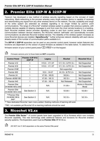
2. Premier Elite 8XP-W & 32XP-W Texecom has developed a new method of wireless security signalling based on the concept of mesh networking. Mesh-networking is the process whereby every single wireless device is capable of receiving and retransmitting any signal from any other wireless device on the network. The size, scalability and range of the entire system are extended as wireless signalling is no longer limited by point-to point communications. The range of a Ricochet® enabled wireless system is greater than previous systems, with multiple devices capable of relaying messages to and from even the most remote locations in a building. Each Ricochet enabled device provides signalling routes to and from control panels. If the wireless communication between devices weakens, the Ricochet network ‘self-heals’ and automatically re-routes communications via alternate Ricochet enabled devices. The reliability of the wireless system increases as more Ricochet devices are installed. SignalSecurity™ further enhances network reliability with each device already aware of the number of communication paths available to it.
The 8XP-W & 32XP-W expanders can be used on any premier control panel; however certain features and functions are dependent on the version of panel firmware as detailed in the table below. To determine the
firmware version of your control panel press / 4 on the keypad.
Firmware versions prior to those listed are NOT compatible.
Control Panel Premier 8 XP-W & 32XP-W
Legacy Ricohet Ricochet V2.xx
Premier 412 1 V10.5 – V11.07 V11.10> & PV1.0> Not Supported
Premier 816 1 V10.5 – V11.07 V11.10> & PV1.0> Not Supported
Premier 816E 0 Not supported
Premier 832 1 V3.5 – V4.07 V4.10> & PV1.0> Not Supported
Premier 24 1 V7.00 – V8.23 V8.24> Not Supported
Premier 48/88/168 1 V7.00 – V8.13 V8.15> Not Supported
Premier 640 1 V7.00 – V8.15 Not Released Not Supported
Premier Elite 24/48/88/168 & 640
1 N/A V1.00> Works in Ricochet
Mode
Premier Elite 24/48/88/168 & 640
See Section 3 N/A V2.00> V2.00>
**Premier Elite 24/48/88/168 &
640* See Section 3 N/A V2.10> V2.10>
** New dedicated Ricochet learn menu added. Existing methods of learning still exist.
*TBC, not available yet Ricochet V2.xx learning methods should be used
3. Ricochet V2.xx The Premier Elite Series™ of control panels have been upgraded to V2.xx firmware which now contains Ricochet capability. This new technology adds additional features and functions for Ricochet enabled security systems. The Expanders used must be Premier Elite XP-W V2.xx.
DO NOT mix V1 &V2 expanders on the same Premier Elite panel
Premier Elite 8XP-W & 32XP-W Installation Manual
4 INS467-6
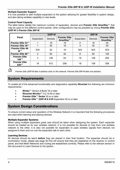
Multiple Expander Support It is now possible to add multiple expanders to the system allowing for greater flexibility in system design, and also taking wireless capability to new levels.
Control Panel Capacity The table below details the maximum number of expanders, devices and Premier Elite SmartKey™ that may be used on the different control panels, other configurations may be possible by mixing Premier Elite 32XP-W & Premier Elite 8XP-W.
Panel 32XP-W 8XP-W
Expanders Devices Premier Elite SmartKey™
Expanders Devices Premier Elite SmartKey™
Premier Elite 24™ 1 16 16 2 16 25 Premier Elite 48™ 1 32 16 4 32 50 Premier Elite 48-
W™ N/A 32 16 N/A N/A N/A
Premier Elite 88™ 2 64 32 8 64 100 Premier Elite
168™ 4 128 64 16 128 200
Premier Elite 640™
16 512 256 16 128 256
Premier Elite 32XP-W take 4 address slots on the network, Premier Elite 8XP-W take one address
System Requirements
To enable all of the advanced functionality and diagnostics capability Ricochet the following are minimum requirements:-
• Wintex™ Version 6 Build 16 or later • Ricochet Monitor™ 0.2.15.00 or later • Premier Elite™ Series V2.xx or later • Premier Elite™ 32XP-W & 8-W Expanders V2.xx or later
System Design Considerations
To ensure correct setup and operation of the Wireless Network it is important that the following procedures are used when learning and placing devices.
Multiple Expander Systems When using multiple expanders great care should be taken when designing the system. Each expander should be treated as its own wireless network; it is not possible for devices to hop from one wireless network to the other, it is also not possible for expanders to pass wireless signals from devices not assigned to them and nor can the expanders talk to each other.
Learning Devices All devices should be learnt before they are placed in their final location. The expander should be in commission mode, please see page 32.This will ensure that they are registered on the receiver or control panel, and that Mesh Networks and routing are established correctly. Please refer to the relevant section in this document to Learn Devices to the system.
Premier Elite 8XP-W & 32XP-W Installation Manual
INS467-6 5
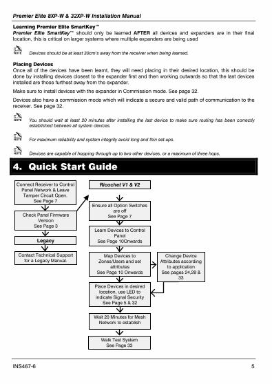
Connect Receiver to Control Panel Network & Leave Tamper Circuit Open.
See Page 7
Learning Premier Elite SmartKey™ Premier Elite SmartKey™ should only be learned AFTER all devices and expanders are in their final location, this is critical on larger systems where multiple expanders are being used
Devices should be at least 30cm’s away from the receiver when being learned.
Placing Devices Once all of the devices have been learnt, they will need placing in their desired location, this should be done by installing devices closest to the expander first and then working outwards so that the last devices installed are those furthest away from the expander.
Make sure to install devices with the expander in Commission mode. See page 32.
Devices also have a commission mode which will indicate a secure and valid path of communication to the receiver. See page 32.
You should wait at least 20 minutes after installing the last device to make sure routing has been correctly established between all system devices.
For maximum reliability and system integrity avoid long and thin set-ups.
Devices are capable of hopping through up to two other devices, or a maximum of three hops.
4. Quick Start Guide
Check Panel Firmware Version
See Page 3
Ricochet V1 & V2
Legacy
Contact Technical Support for a Legacy Manual.
Ensure all Option Switches are off
See Page 7
Learn Devices to Control Panel
See Page 10Onwards
Map Devices to Zones/Users and set
attributes See Page 10 Onwards
Place Devices in desired location, use LED to
indicate Signal Security See Page 5 & 32
Wait 20 Minutes for Mesh Network to establish
Walk Test System See Page 33
Change Device Attributes according
to application See pages 24,28 &
33

Premier Elite 8XP-W & 32XP-W Installation Manual
6 INS467-6
5. System Overview
1: Engineers Keypad Connection An engineer’s keypad (Premier/Elite LCD keypad and interface lead) can be temporarily plugged onto this connector to allow system programming and testing. (Functions dependent on Panel firmware version) Set the keypad address switches to all on. 2: Network Connection The + and – terminals provide power whilst the T and R terminals are transmit and receive data. 3: For Future Use 4: Comm. Port Connection Serial communications port for connecting the 8 XP-W & 32XP-W to a PC via PC Com/USB Com or Com IP for use with Ricochet MonitorSoftware. 5: Lid Tamper When open puts the system into commission mode and digitally attenuates the receiver signal by 15Db. 6: Programming LED’s Allows programming of devices directly to the receiver, in conjunction with the learn switch. 7: Antenna RF Antenna.
1 2 3 4 5 6 7 8
1
ON
2 43 1
ON
2 43
1 2 3 4 1 2 3 4
Premier Elite 8XP-W & 32XP-W Installation Manual
INS467-6 7
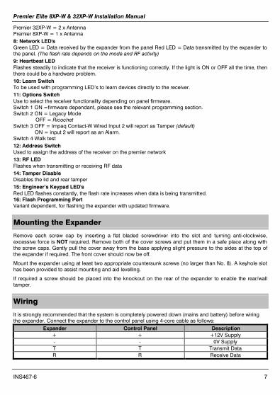
Premier 32XP-W = 2 x Antenna Premier 8XP-W = 1 x Antenna 8: Network LED's Green LED = Data received by the expander from the panel Red LED = Data transmitted by the expander to the panel. (The flash rate depends on the mode and RF activity) 9: Heartbeat LED Flashes steadily to indicate that the receiver is functioning correctly. If the light is ON or OFF all the time, then there could be a hardware problem. 10: Learn Switch To be used with programming LED’s to learn devices directly to the receiver. 11: Options Switch Use to select the receiver functionality depending on panel firmware. Switch 1 ON =firmware dependant, please see the relevant programming section. Switch 2 ON = Legacy Mode
OFF = Ricochet Switch 3 OFF = Impaq Contact-W Wired Input 2 will report as Tamper (default)
ON = input 2 will report as an Alarm. Switch 4 Walk test 12: Address Switch Used to assign the address of the receiver on the premier network 13: RF LED Flashes when transmitting or receiving RF data 14: Tamper Disable Disables the lid and rear tamper 15: Engineer’s Keypad LED's Red LED flashes constantly, the flash rate increases when data is being transmitted. 16: Flash Programming Port Variant dependent, for flashing the expander with updated firmware.
Mounting the Expander
Remove each screw cap by inserting a flat bladed screwdriver into the slot and turning anti-clockwise, excessive force is NOT required. Remove both of the cover screws and put them in a safe place along with the screw caps. Gently pull the cover away from the base applying slight pressure to the sides at the top of the expander if required. The front cover should now be off.
Mount the expander using at least two appropriate countersunk screws (no larger than No. 8). A keyhole slot has been provided to assist mounting and aid levelling.
If required a screw should be placed into the knockout on the rear of the expander to enable the rear/wall tamper.
Wiring
It is strongly recommended that the system is completely powered down (mains and battery) before wiring the expander. Connect the expander to the control panel using 4-core cable as follows:
Expander Control Panel Description + + +12V Supply - - 0V Supply T T Transmit Data R R Receive Data
Premier Elite 8XP-W & 32XP-W Installation Manual
8 INS467-6
The networks are made up of four terminals incorporating power and data. To ensure correct operation, all four terminals on the device must be connected to the corresponding terminals on the control panel or previous device.
Expanders can be connected using 4-core cable. However, it is recommended that 6 or 8-core cable is used as the spare cores can be used to ‘Double Up’ on the power connections if needed.
Standard 7/0.2 alarm cable can be used for most installations. However, under certain conditions it may be necessary to use screened cable.
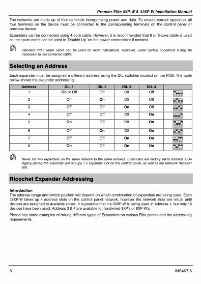
Selecting an Address
Each expander must be assigned a different address using the DIL switches located on the PCB. The table below shows the expander addressing:
Address DIL 1 DIL 2 DIL 3 DIL 4 1 On or Off Off Off Off 2 4 3 1 2 Off On Off Off 2 4 3 1 3 Off Off On Off 2 4 3 1 4 Off Off Off On 2 4 3 1 5 On Off Off On
2 4 3 1 6 Off On Off On 2 4 3 1 7 Off Off On On
2 4 3 1 8 On Off On On
2 4 3 1
Never set two expanders on the same network to the same address. Expanders are factory set to address 1.On legacy panels the expander will occupy 1 x Expander slot on the control panel, as well as the Network Receiver slot.
Ricochet Expander Addressing
Introduction The address range and switch position will depend on which combination of expanders are being used. Each 32XP-W takes up 4 address slots on the control panel network, however the network slots are virtual until devices are assigned to available zones. It is possible that if a 32XP-W is being used at Address 1, but only 16 devices have been used, Address 3 & 4 are available for hardwired 8XP's or 8XP-W's.
Please see some examples of mixing different types of Expanders on various Elite panels and the addressing requirements.
Premier Elite 8XP-W & 32XP-W Installation Manual
INS467-6 9
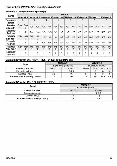
Example 1 Totally wireless system(s)
Panel 32XP-W
Network 1 Network 2 Network 3 Network 4 Network 5 Network 6 Network 7 Network 8 Expanders
(Max) 2 2 2 2 2 2 2 2
Premier Elite 88™
Exp 1
Exp 2 N/A N/A N/A N/A N/A N/A N/A N/A N/A N/A N/A N/A N/A N/A
Expander Address 1 5 N/A N/A N/A N/A N/A N/A N/A N/A N/A N/A N/A N/A N/A N/A
Premier Elite 168™
Exp 1
Exp 2
Exp 1
Exp 2
N/A N/A N/A N/A N/A N/A N/A N/A N/A N/A N/A N/A
Expander Address
1 5 1 5 N/A N/A N/A N/A N/A N/A N/A N/A N/A N/A N/A N/A
Premier Elite 640™
Exp 1
Exp 2
Exp 1
Exp 2
Exp 1
Exp 2
Exp 1
Exp 2
Exp 1
Exp 2
Exp 1
Exp 2
Exp 1
Exp 2
Exp 1
Exp 2
Expander Address
1 5 1 5 1 5 1 5 1 5 1 5 1 5 1 5
Example 2 Premier Elite 168™, + 32XP-W, 8XP-W's & 8XP's mix
Panel Network 1 Network 2 Expanders (Wireless) Expanders (Mixed)
Premier Elite 168™ 32XP-W 2 x 8XP-W 8XP-W 8XP-W 8XP 8XP Expander Address 1 5 & 6 1 2 3 4
Devices (Max) 32 16 8 8 8 8 Premier Elite SmartKey™(Max) 16 16 16 16 N/A N/A
Example 3 Premier Elite™48, 32XP-W + 8XP's
Panel Network 1 Expanders (Mixed)
Premier Elite 48™ 32XP-W 2 x 8XP Expander Address 1 5 & 6
Devices Used 16 16 Premier Elite SmartKey™(Max) 16 N/A
Premier Elite 8XP-W & 32XP-W Installation Manual
10 INS467-6
6. Programming For all Legacy Control panels, please contact Technical Support to obtain a legacy manual.
It is highly recommended that you upgrade the Panel Firmware to the latest version to ensure full compatibility; however the system is backwards compatible as detailed in the table on page 3.
It is not possible to upgrade Premier panels to Premier Elite firmware.
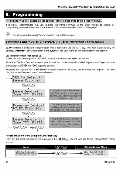
Premier Elite™ V2.10> 12/24/48/88/168 Ricochet Learn Menu
V2.10 contains a dedicated Ricochet learn menu accessible via the key. This new feature is only for devices, SmartKey™ should be learnt to the system in the User Menu as described later in this section.
Learn Devices from first power up Follow the instructions given in INS176-8 or later for the first power up of the system.
When the "Confirm Devices" menu appears check and make sure all installed Keypads and Expanders are
showing; press and again to confirm.
Providing the system has a Ricochet® enabled expander installed, the following will appear. The flow diagram shows the procedure to learn devices:-
YES to Select:-
Learn Ricochet
/y
Learn Device?
Zone ??? N?,E??
Power up Device!
N?, E?, D?? �- 20s
Learn Device to
Zone ??? N?,E??
The bottom line of text showsthe one number, the etwork
and the xpander the device willbe learned too.
Z NE
The bottom line of text showsthe etwork the xpander and
the device s lot on the expander.N E
/y
/y
/y
Use the / or to select different zones . It is onlyposs ible to selec t Zones which
are free.
nn U
/
Access the Learn Menu using the Omit “Hot” key From any top level engineering menu pressing the /key will take you to the Ricochet learn menu above.
Menu / Ricochet Learn Menu
YES to Select:-
???????????????? / YES to Select:-
Learn Ricochet

Premier Elite 8XP-W & 32XP-W Installation Manual
INS467-6 11
IMPORTANT In all cases when entering the Learn menu the next available free Zone will be chosen to learn a device too. It will not be possible to learn a device to a Zone that already has a device learned too it. The number of expander’s on the system will dictate which next “free” zone is chosen to learn too.
When all device slots have been used the following screen will be shown
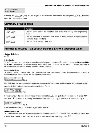
All Devices
Learnt!
Pressing the /key will return you to the Ricochet® learn menu; pressing the /key will enter the Delete devices menu.
Auto Zone Type & Area
When learning devices, if no editing has taken place of the control panel onboard hardwired zones, these will be switched to Not Used after the first Ricochet® device is learned to the system; the following defaults will be used for Ricochet® devices learned to the system.
Zone Type Area 001-008 Not Used N/A
009 Entry/Exit 1 A 010 Guard Access A
011 & above Guard A
IMPORTANT If any editing of any of the on board control panel zones is carried out BEFORE any Ricochet devices are learned too the system, the control panel zones will remain at factory defaults.
Deleting Devices
Delete Devices To delete devices from the system, access the Ricochet Learn menu. Any of the methods previously detailed may be used.
The / key is used to access the Delete option.
Follow the flow diagram to delete devices from the system.
YES to Select:-
Learn Ricochet
/y
Learn Device
Zone ??? N?,E?
Delete Device?
Zone ??? N?,E?
Use the / or to select different zones . It is onlyposs ible to selec t Zones which
have devices learned.
nn U
The / key will cyc lebetween the Learn or Delete
options .
/
//y
If all devices are deleted from the system the following will be shown
Premier Elite 8XP-W & 32XP-W Installation Manual
12 INS467-6
All Devices
Deleted!
Pressing the /key will return you to the Ricochet learn menu; pressing the /key will enter the Learn devices menu.
Summary of Keys used
Key Function
/ Use this key to access the Ricochet Learn menu from any top level engineering menu.
/ Use this key when in Ricochet Learn menu to delete devices, or cycle between learn and delete functions
/ Use this key to exit the Learn Menu.
Premier EliteV2.00 - V2.09 24/48/88/168 & 640 + Ricochet V2.xx
Option Switches All Off
Introduction V2.xx firmware added the option to learn Ricochet devices through the Zone Setup Menu, and Premier Elite SmartKey™ are learned through the User Setup menu, the "Configure Radio" menu in Engineer's Utilities is now redundant and should only be used for Legacy systems.
Learning Devices To learn a device to a Zone select the Zone from the Zone Setup Menu, Zones that are capable of having a Ricochet device learnt to them will be displayed as follows:-
Zone P,Not sed Fig 1
Fig 1indicates the pre-assigned zone number, the expander being used and the device slot on the expander.
Once a device has been learnt the display will be as Fig 2:-
Zone Learn:PR P-, Fig 2
If you are unsure if a zone already has a device learned to it, you can go to the menu as in Fig 1, press
and then if a device is already learnt the display will look like Fig 2, if not then it will look like Fig 3
Zone Learn:ree P-, Fig 3
Please see the diagram on the next page to learn devices.
Deleting Devices To delete devices from the expander is the same as learning them; choose the zone you wish to delete, and
follow the procedure to learn the device, when the screen shows “Learning” press .
Premier Elite 8XP-W & 32XP-W Installation Manual
INS467-6 13
Device Modes of Operation
Always Awake This mode should only be used on devices which are required to signal at all times and is the default setting for the Impaq Contact-W and Impaq Plus-W.
Auto Mode When in Auto Mode, devices poll at 15 minute intervals. Following activation, devices will not transmit the same activation again for a period of 3 minutes.
Hybrid Mode Hybrid mode is used to control the reporting functions for devices. When in the mode devices are asleep when the system is set, and are woken up by the control panel at the point of arming. When the system is disarmed the devices will be put back to sleep. This mode of operation is the default mode for XT-W, QD-W & DT-W.
On very large systems (100 devices +) a small delay may be experienced when arming the system, this is normal as the expanders on the system wake up the relevant devices.
Premier Elite DT-W should ALWAYS be used in Hybrid mode, failure to do this will have an adverse affect on battery life.
Expander O/P Mode Expander O/P modes are for future use and should not be used with any of the devices listed above.
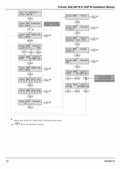
Zone Types & Attributes detailed instructions for programming can be found in INS176-8 or later.
To Learn Devices through the Zone Setup menu please follow the diagram on the next page.
Premier Elite 8XP-W & 32XP-W Installation Manual
14 INS467-6
Zone Panel
Not sed
Yes to Select:-
Zone Setup
y
?
E nter zone numbere.g 009 = Zone 009
Zone P,Not sed
Zone Learn:
Learning... 2s
Zone Learn:PR P-,
y
Zone P,
Not sed *
*y
Zone Attrib * * * * * * * * *y
Zone Attrib2 * * * * * A * * *
Zone Areas:
A....... *
y
Zone Text:*
y
Zone Chime:
Silent *
y
Zone Test:
Remote Test Off *
y
Zone Mode:
Hybrid *
y
Zone Group: *
y
y
Zone Learn:PR P-,
U
Zone Learn:ree P-,2
y
Use the sc roll keyto select the next
zone to learn a device too
* Please refer to INS 176 “Zone S etup” for details when us ing
the key to change these s ettings

Premier Elite 8XP-W & 32XP-W Installation Manual
INS467-6 15
Premier Elite SmartKey™
Introduction Premier Elite SmartKey™ are now learnt and all functionality managed through the “Setup Users” Menu.
Ricochet and Premier Elite Series V2.xx firmware upgrades add additional capabilities to the management of Premier Elite SmartKey™. In multiple expander systems it is now possible to choose which zones (and therefore expander) the Premier Elite SmartKey™ will use for its routeing, LED and Aux functions can also be changed within the “Setup Users” menu.
All users on the system can have a Premier Elite SmartKey™ a TAG and a code, or any combination of them.
This section only deals with Premier Elite SmartKey™ learning and routeing, all other user programmable options can be found in INS176-8 or later Premier Elite Series Installation Manual.
Great care should be taken when using large numbers of Premier Elite SmartKey™, only one Premier Elite SmartKey™ per expander can be used by the system at any one time, and on Multiple expanders systems, or large sites, functionality should be checked in all areas of the site where the device may be used.
Premier Elite SmartKey™ Routeing Premier Elite SmartKey™ should only be learned to the system AFTER all devices have been learned and placed in their final location. Whilst it is possible to learn at any point during the programming of the system, learning and testing the functionality of the Premier Elite SmartKey™ after all devices have been placed will ensure that the Premier Elite SmartKey™ performs as expected, and works in locations where the user would expect it too.
Route By The Route By function allows you to select which Zones (and therefore expander) the Premier Elite SmartKey™ will use on the system for its routeing. This should be selected BEFORE the device has been learned.
In the examples below Fig 1 shows the zones associated with Expander 1, which is a 32XP-W, and Fig 2 shows Expander 2 which is also a 32XP-W, when using 8XP-W there will obviously be less devices that the Premier Elite SmartKey™ can use.
ser Route By
Zones - 4 Fig 1
ser Route By
Zones 4 - 72 Fig 2
The key is used to select this menu and the U key used to select which expander and associated zones will be used
Once a Premier Elite SmartKey™ has been learned the key will show which zones are being used for routeing. It is not possible to alter this once learned. To change the routeing the Premier Elite SmartKey™ should be deleted and the process started from the beginning.
Deleting a Premier Elite SmartKey™ Deleting the Premier Elite SmartKey™ from the user is a similar process to learning, at the appropriate point
in the menu press followed by , the Premier Elite SmartKey™ will be removed from the User. To delete all user data see INS176-8 or later.

Premier Elite 8XP-W & 32XP-W Installation Manual
16 INS467-6
Learning Premier Elite SmartKey™
Setup sers
ser2:
YES to Select:-
Setup sers
y
O
ser2 Ricochetob --- Aux
ser2 Ricochet
Learning... 2s
ser2 Ricochetob LED Aux
?
ser2 Ricochet
ree
**1
2
to toggle L E D on or off to toggle Aux on or off
* Please refer to INS 467“Premier E lite S martKey”for further details on the LE D & Aux functions .
ser2 Route By
Zones - 4
Using the key at this point allows you to view the group of zones ,
a nd therefore the expander that the S ma rtKey will use.
Use the key to select the groupof Zones and E xpander you want to use
U
U
ser2 Route By
Zones - 4
U
Use scrollto next userU
Once the 16 slots on a XP-W are taken up, the learn process will fail and display 'No spaces left'.
In either of the Premier Elite SmartKey™ menu displays, any Premier Elite SmartKey™ that logs onto the system will cause the menu to change to that Premier Elite SmartKey™ - a handy way of finding out which user a Premier Elite SmartKey™ in your hand belongs to!
Premier Elite V1.00 & Premier 24 V8.24, 48/88/168 V8.15>later
When using the 8XP-W it is only possible to learn devices to slots 1-8 on the expander. Slots 9-32 will still be shown in Ricochet Monitor, and on the keypad, however no devices can be learned to them.
Option Switch Settings All Off
Configuring Radio devices Up to 32 wireless devices of any combination can be learnt on to the system. The number of SmartKey™ is limited to the maximum number of users (i.e. 50 0n the Premier Elite 48).

Premier Elite 8XP-W & 32XP-W Installation Manual
INS467-6 17
On the 8XP-W the maximum number of devices including Smartkey™ is 8.
Wireless devices can then be mapped on to the system along with conventional detectors.
The top line on the display shows the serial number of the device and also the status i.e. Active, Tamper etc.
The bottom line of the display shows the signal strength and also which zone/user the device is mapped to.
Signal strength should be greater than 30.
Signal strength is only displayed when in commission mode. When not in commission mode the keypad will display 255.
The signal range is between 0 and 99
In the case of devices that are hopping the display on the panel keypad shows the average of the hopped signal strengths.
Follow the instructions on the next page to learn devices to the system, once complete follow the instructions in the relevant control panel manual to programme zone type, attributes and user permissions. Place devices in their final location ONLY after they have been learned to the system.
Engineer tils
Configure Radio
23: D4DD3C3 OK
SL:85 Zone>
YES to Select:-
Engineer tils
Engineer tilsView Event Log
23: No Device 2 ,YES, To Learn
23: D4DD3C3 OK
SL:85 Zone>8
23: D4DD3C3 OK
SL:85 Zone 8
: D2654 OKSL: Zone
23: No Device 8Activate Device
23: D4DD3C3 TAMP
SL:85 Zone
Press Learn switch and insert battery/Power up SmartKey.
y/
y/
/
n/n
U
U
?
Press YES to learnRadio Device
Use keys 0 - 9 to enter therequired device number oruse the SCROLL key to searche.g. 23 = Device 23
Press NO to map thedevice to a zone/user
Use keys 0 - 9 to enter therequired zone/user number oruse the SCROLL key to searche.g. 18 = Zone 18
Top Line = Serial numberof device
Bottom and status
Line = Signal st rengthand zone/user number
Press RESET to DeleteRadio Device
If Device already programmedID will show here
If Device already programmed ID will show here
y/
y/
Premier Elite 8XP-W & 32XP-W Installation Manual
18 INS467-6
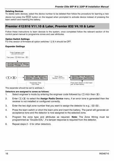
Deleting Devices To delete radio devices, select the device number to be deleted then follow the procedure for learning a new
device but press the button on the keypad when prompted to activate device instead of pressing the learn switch and inserting the battery.
Premier 412/816 V11.10 & Later, Premier 832 V4.10 & Later
Follow these instructions to learn devices to the system, once completed follow the relevant section of the control panel manual to programme zones and user attributes.
Option Switch Settings For this version of firmware all option switches 1,2 & 4 should be OFF.
Expander Settings
The expander should be set to address 1.
Detectors are assigned to zones as follows: 1. Select engineer’s mode by entering the engineer code followed by / then .
2. Enter to select the Assign Radio Device menu, if an error tone is generated then the receiver is not installed or configured correctly.
3. Enter the two digit zone number that you want to assign the detector to e.g., .
4. Press the learn switch or short the learn pins and insert the battery. The panel will generate an acceptance tone and the detector is now assigned to the selected zone.
5. Program the zone type and attributes as required. Note: The Zone Wiring must be programmed as “Double EOL”, if a tamper response is required from the detector.
6. Repeat steps 2 - 5 for other detectors.
Programming MenuEnter Code > ??
Assign RadioEnter Zone No.??
Enter ZoneNumber ??
Assign ?? RadioActivate Devic2
Enter Engineers code
Then press then/
????
Acceptance Tonefrom Panel
Press learn Switch or short learn pins & Insert battery
Premier Elite 8XP-W & 32XP-W Installation Manual
INS467-6 19
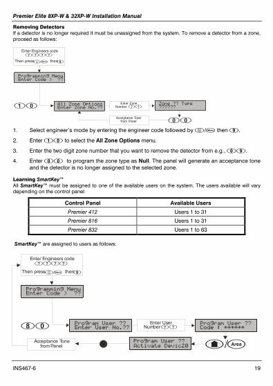
Removing Detectors If a detector is no longer required it must be unassigned from the system. To remove a detector from a zone, proceed as follows:
1. Select engineer’s mode by entering the engineer code followed by / then .
2. Enter to select the All Zone Options menu.
3. Enter the two digit zone number that you want to remove the detector from e.g., .
4. Enter to program the zone type as Null. The panel will generate an acceptance tone and the detector is no longer assigned to the selected zone.
Learning SmartKey™ All SmartKey™ must be assigned to one of the available users on the system. The users available will vary depending on the control panel:
Control Panel Available Users
Premier 412 Users 1 to 31
Premier 816 Users 1 to 31
Premier 832 Users 1 to 63
SmartKey™ are assigned to users as follows:
Programming MenuEnter Code > ??
All Zone OptionsEnter Zone No.??
Enter ZoneNumber ??
Zone ?? Type??????
Enter Engineers code
Then press then
/
????
Acceptance Tonefrom Panel
Programming MenuEnter Code > ??
Program ser ??Enter ser No.??
Enter UserNumber ??
Program ser ??Code : ******
Enter Engineers code
Then press then
/
????
Acceptance Tonefrom Panel A/AProgram ser ??
Activate Devic2
Premier Elite 8XP-W & 32XP-W Installation Manual
20 INS467-6
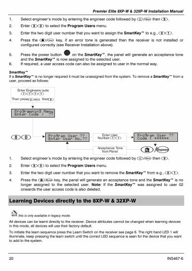
1. Select engineer’s mode by entering the engineer code followed by / then .
2. Enter to select the Program Users menu.
3. Enter the two digit user number that you want to assign the SmartKey™ to e.g., .
4. Press the A/A key, if an error tone is generated then the receiver is not installed or configured correctly (see Receiver Installation above).
5. Press the power button on the SmartKey™, the panel will generate an acceptance tone and the SmartKey™ is now assigned to the selected user.
6. If required, a user access code can also be assigned to user in the normal way.
SmartKey™ If a SmartKey™ is no longer required it must be unassigned from the system. To remove a SmartKey™ from a user, proceed as follows:
1. Select engineer’s mode by entering the engineer code followed by / then .
2. Enter to select the Program Users menu.
3. Enter the two digit user number that you want to remove the SmartKey™ from e.g., .
4. Press the / key, the panel will generate an acceptance tone and the SmartKey™ is no longer assigned to the selected user. Note: If the SmartKey™ was assigned to user 02 onwards the user access code is also deleted.
Learning Devices directly to the 8XP-W & 32XP-W
this is only available in legacy mode.
All devices can be learnt directly to the receiver. Device attributes cannot be changed when learning devices in this mode, all devices will use their factory default.
To initiate the learn sequence press the Learn Switch on the receiver see page 6. The right hand LED 1 will illuminate, keep pressing the learn switch until the correct LED sequence is seen for the device that you want to add to the system.
Programming MenuEnter Code > ??
Program ser ??Enter ser No.??
Enter UserNumber ??
Program ser ??Code : ******
Enter Engineers code
Then press then
/
????
Acceptance Tonefrom Panel /
Premier Elite 8XP-W & 32XP-W Installation Manual
INS467-6 21
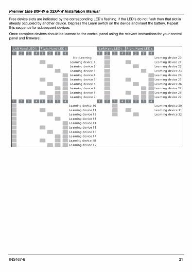
Free device slots are indicated by the corresponding LED’s flashing, if the LED’s do not flash then that slot is already occupied by another device. Depress the Learn switch on the device and insert the battery. Repeat this sequence for subsequent devices.
Once complete devices should be learned to the control panel using the relevant instructions for your control panel and firmware;
L eft H and LE D’s
R ight H and LE D ’s
L eft H and LE D’s
R ight H and LE D ’s
1
2
3
4
1
2
3
4
1
2
3
4
1
2
3
4
Not Learning
Learning device 20
Learning device 1
Learning device 21
Le arning devic e 2
Learning device 22
Le arning devic e 3
Le arning devic e 23
Le arning devic e 4
Learning device 24
Le arning devic e 5
Learning device 25
Le arning devic e 6
Le arning devic e 26
Le arning devic e 7
Learning device 27
Le arning devic e 8 Learning device 28
Le arning devic e 9
Learning device 29
1
2
3
4 1
2
3
4 1
2
3
4 1
2
3
4
Learning device 10
Le arning devic e 30
Le arning devic e 11
Le arning devic e 31
Le arning devic e 12
Le arning devic e 32
Le arning devic e 13
Le arning devic e 14
Le arning devic e 15
Le arning devic e 16
Le arning devic e 17
Learning devic e 18
Le arning devic e 19
Premier Elite 8XP-W & 32XP-W Installation Manual
22 INS467-6
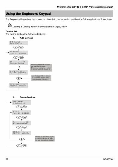
Using the Engineers Keypad
The Engineers Keypad can be connected directly to the expander, and has the following features & functions.
Learning & Deleting devices is only available in Legacy Mode
Device list The device list has the following features:-
1. Add Devices
Eng Keypad
:Device List
No Dev .. ..
Poll:xx Dxxxxxx
y/
PR ... T ..Poll: D4DD3C3
... ... .. 2Activate Device
Act ivate Learn switch on deviceand insert battery within20 seconds, release learn switchor remove jumper & Replace lid
No Dev .. ..Poll:xx Dxxxxxx
Use the Up and Down arrows or the number keys to select the next device to be learnt
y/
U
2. Delete Devices
Eng Keypad
:Device List
PR ... .. ..
Poll: D4DD3C3
... ... .. 2Activate Device
Use the Up and Down arrows or the number keys to select the next device to be deleted
No Dev .. ..Poll:xx Dxxxxxx
y/
y/
/
y/
U
Premier Elite 8XP-W & 32XP-W Installation Manual
INS467-6 23
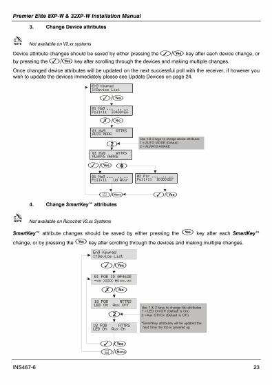
3. Change Device attributes
Not available on V2.xx systems
Device attribute changes should be saved by either pressing the y/ key after each device change, or
by pressing the y/ key after scrolling through the devices and making multiple changes.
Once changed device attributes will be updated on the next successful poll with the receiver, if however you wish to update the devices immediately please see Update Devices on page 24.
Eng Keypad
:Device List
Mag ... .. ..
Poll: D4DDE6
Mag ATTRSATO MODE
Use 1 & 2 keys to change device attributes1 = AUTO MODE (Default)2 = ALWAYS AWAKE
Mag ATTRSALAYS AAKE
Mag ... .. ..Poll: d Attr
2 Pir ... .. ..Poll: D3DD2E7
y/
n/n
2
y/
y//
U
4. Change SmartKey™ attributes
Not available on Ricochet V2.xx Systems
SmartKey™ attribute changes should be saved by either pressing the y key after each SmartKey™
change, or by pressing the y key after scrolling through the devices and making multiple changes.
Eng Keypad
:Device List
OB D 462B
-xx H:xx,xx
8 OB ATTRSLED On Aux Off
Use 1 & 2 keys to change fob attributes1 = LED On/Off (Default is On)2 = Aux Off/On (Default is Off)
*SmartKey attributes will be updated the next time the fob is powered up.8 OB ATTRS
LED On Aux On
y/
n/n
2
y//
Premier Elite 8XP-W & 32XP-W Installation Manual
24 INS467-6
Once changed Premier Elite SmartKey™ attributes will be updated the next time the Premier Elite SmartKey™ is powered on; if however you wish to update the devices immediately please see Update Devices on page 24
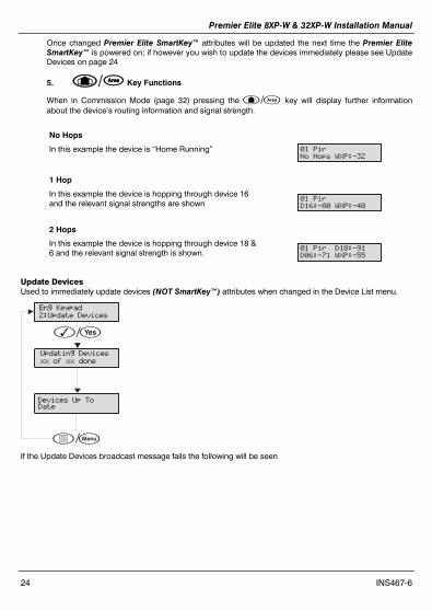
5. A/ Key Functions
When in Commission Mode (page 32) pressing the A/A key will display further information about the device’s routing information and signal strength.
No Hops
In this example the device is “Home Running” Pir
No Hops P:-32
1 Hop
In this example the device is hopping through device 16 and the relevant signal strengths are shown
Pir
D6:-8 P:-48
2 Hops
In this example the device is hopping through device 18 & 6 and the relevant signal strength is shown.
Pir D8:-
D6:-7 P:-55
Update Devices Used to immediately update devices (NOT SmartKey™) attributes when changed in the Device List menu.
pdating Devices
xx of xx done
Devices p ToDate
Eng Keypad
2:pdate Devices
y/
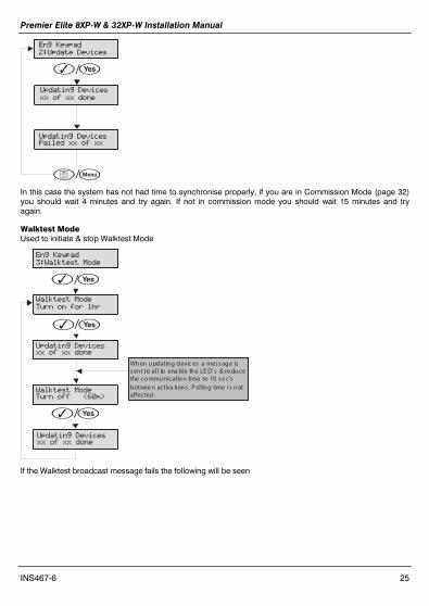
/ If the Update Devices broadcast message fails the following will be seen
Premier Elite 8XP-W & 32XP-W Installation Manual
INS467-6 25
pdating Devices
xx of xx done
pdating Devicesailed xx of xx
Eng Keypad
2:pdate Devices
y/
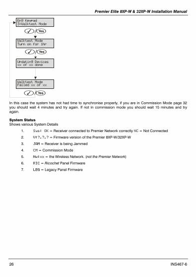
/ In this case the system has not had time to synchronise properly, if you are in Commission Mode (page 32) you should wait 4 minutes and try again. If not in commission mode you should wait 15 minutes and try again.
Walktest Mode Used to initiate & stop Walktest Mode
Eng Keypad
3:alktest Mode
alktest Mode
Turn on for hr
pdating Devicesxx of xx done
Wh en u pdatin g devic es a messag e issen t to al l to ena ble th e LE D’ s & re du ce the co mmu nicatio n time to 10 se c’sbetwee n activa tion s . P ol lin g time is n otaffected.
alktest ModeTurn off (6m)
pdating Devicesxx of xx done
y/
y/
y/
If the Walktest broadcast message fails the following will be seen
Premier Elite 8XP-W & 32XP-W Installation Manual
26 INS467-6
Eng Keypad
3:alktest Mode
alktest Mode
Turn on for hr
y/
pdating Devicesxx of xx done
alktest Modeailed xx of xx
y/
y/
In this case the system has not had time to synchronise properly, if you are in Commission Mode page 32 you should wait 4 minutes and try again. If not in commission mode you should wait 15 minutes and try again.
System Status Shows various System Details
1. Sys: OK = Receiver connected to Premier Network correctly NC = Not Connected
2. V:?.?.? = Firmware version of the Premier 8XP-W/32XP-W
3. AM = Receiver is being Jammed
4. CM = Commission Mode
5. Nw:xx = the Wireless Network. (not the Premier Network)
6. RC = Ricochet Panel Firmware
7. LEG = Legacy Panel Firmware
Premier Elite 8XP-W & 32XP-W Installation Manual
INS467-6 27
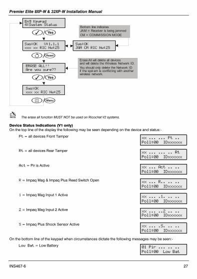
Eng Keypad4:System Status
Sys:OK V:..
xxx xx RC Nw:25
y/
ERASE ALL!!
Are you sure??
Erase All will delete all devicesand will delete the Wireless Network ID.You should only delete the Network IDif the syst em is conflict ing with anotherwireless network.
Sys:OK
xxx xx RC Nw:25
Sys:OK
AM CM RC Nw:25
Bottom line indicatesJAM = Receiver is being jammedCM = COMMISSION MODE
/
y/
/
The erase all function MUST NOT be used on Ricochet V2 systems.
Device Status Indications (V1 only) On the top line of the display the following may be seen depending on the device and status:-
t = all devices Front Tamper
Rt = all devices Rear Tamper
Act = Pir is Active
R = Impaq Mag & Impaq Plus Reed Switch Open
= Impaq Mag Input 1 Active
2 = Impaq Mag Input 2 Active
S = Impaq Plus Shock Sensor Active
On the bottom line of the keypad when circumstances dictate the following messages may be seen:-
Low Bat = Low Battery
xx ... ... t ..
Poll: Dxxxxxx
xx ... ... .. Rt
Poll: Dxxxxxx
xx ... Act .. ..
Poll: Dxxxxxx
xx ... R.. .. ..
Poll: Dxxxxxx
xx ... .. .. ..
Poll: Dxxxxxx
xx ... ..2 .. ..
Poll: Dxxxxxx
xx ... .S. .. ..
Poll: Dxxxxxx
Pir ... .. ..
Poll: Low Bat

Premier Elite 8XP-W & 32XP-W Installation Manual
28 INS467-6
No nfo = Receiver has just powered up and has not heard from the device
Dev lt = Device Fault
d Attr = Shows when Device Attributes have been updated on the receiver but the device has not polled in or been updated by the Update Devices menu. This display also shows which devices are still out of date if the Update Devices broadcast message fails.
Poll Error= Device has not polled in and has been lost on the system.
7. Ricochet Diagnostics (V2.xx) Engineer Utilities now includes a new Ricochet Diagnostics menu. This menu displays information about the live system, and is split into Premier Elite SmartKey™ and Ricochet devices via Zones and Users.
Devices For Devices the following information can be viewed:-
• Routeing • RSSI • Alarms and Status • Device visibility • Time since last message
Premier Elite SmartKey™ For Premier Elite SmartKey™ the following information can be viewed:-
• Routeing • RSSI • Premier Elite SmartKey™ Button • Status
Interpreting Keypad Displays
Routeing The image below shows that Zone 009 is routeing through 14 and then 7 to the expander, for Premier Elite SmartKey™ this may vary depending on where & when the reading is taken. If question marks appear in the display it means the information is not available.
Zone PR
->4->7->P
RSSI Each value in the image below represents the RSSI levels in dBm at each of the hops. If question marks appear on the display it means the information is not available.
Zone PR
6>> 8>> 57 P@
Pir ... .. ..
Poll: No nfo
Pir ... .. ..
Dev ltPoll:
Pir ... .. ..
Poll: d Attr
Pir ... .. ..
Dev ltPoll:

Premier Elite 8XP-W & 32XP-W Installation Manual
INS467-6 29
If question marks appear it could be because either the system has just been powered up and information has not been collected yet, or on large systems the information is not in memory. To populate the display activate the device and the information should appear.
Device Messages
Zone
Not Ricochet
The chosen zone does not have a Ricochet device learned to it.
Zone PR
Msg ??? mins ago
shows the last time the device communicated this represents the last message and could be a poll, activation or tamper etc.....
Zone PR
>hr since msg This is a warning showing that the last communication from the device was over an hour ago.
Zone PR
No msg recvd yet
This display shows that no message has been received yet, this would normally be seen on a recently powered up system, wait 15 minutes from power up before checking the diagnostics information.
Signal Security™
Zone Shock
????
This display shows information relating to signal security on an 8XP-W. 4 windows are available to show information; each window represents two devices, (Odd & Even device slots). Each window could show any of the information detailed in the table below
? No information is available
_ The chosen device cannot “see” either of the devices
O The chosen device can see the ODD device(s)
E The chosen device can see the EVEN device(s)
B The chosen device can see BOTH devices
Example Zone Shock
_OEB
In this example Zone 9 can see the devices as detailed below, use the scroll key to view information about other devices:-
Display _ O E B
Device 1 2 3 4 5 6 7 8
Can see
On the 32XP-W there are 16 windows to show information from the 32 devices of the system; the format is the same.

Premier Elite 8XP-W & 32XP-W Installation Manual
30 INS467-6
Device Status Zone Shock
Status: aaaSpdtt
Secure/OK Active/Fault Type a A Mag1 a A Mag2/Sho a A Reed/PIR s S Poll/Supervision p P Power/Battery d D Device t T Rear t T Front
Premier Elite SmartKey™ Messages
ser Ricochet
Not Ricochet
The chosen user does not have a Premier Elite SmartKey™ associated with them.
ser2 Ricochet
Not connected
The Premier Elite SmartKey™ is not switched on
ser2 Ricochet
Logon Bat OK
Shows the battery is OK and the fob has logged onto the system.
ser2 Ricochet
Partarm Bat OK
Shows the different messages displayed when the relevant buttons are pressed.
ser2 Ricochet
Disarm Bat OK ser2 Ricochet
ullarm Bat OK ser2 Ricochet
Aux? Bat OK
Shows which Aux button has been pressed when in Function Mode.
ser2 Ricochet
Panic Bat OK
Shows the Panic function has been activated
YES to erase
unknown keyfobs
Use this option ONLY if the panel has been replaced and not all Premier Elite SmartKey™ are recognised by the new panel, or if the error tone is heard when learning new Premier Elite SmartKey™
This option DOES NOT remove known Premier Elite SmartKey™, use the Delete option in Setup Users.
Premier Elite 8XP-W & 32XP-W Installation Manual
INS467-6 31
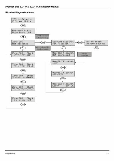
Ricochet Diagnostics Menu
Engineer tils
View Event Log
YES to Select:-
Engineer tils
y
U
Zone ShockStatus: aaaSpdtt
?
Zone Shock
->???->???->P
Zone Shock ??>> ??>> ?? P
C
Zone
Not Ricochet
C
E nter the Zone/UserNumber to view
O ser Ricochet
Not Ricochet
Use to sc rollto R ic oc het DiagU
?
ser2 Ricochet
Not connected
Turn onS ma rtKey
@
Zone Shock????????????????
C
Zone Shock>hr since msg
C
C
ser2 Ricochet->P
ser2 Ricochet->> P
C
@
ser2 RicochetLogon Bat OK
C
C
YES to erase
unknown keyfobs
y
Premier Elite 8XP-W & 32XP-W Installation Manual
32 INS467-6
8. Modes of Operation
Commission Mode
Expander The expander has a Commission Mode, which when operated ensures secure communications with devices on the system. Commission Mode is automatically enabled when the expander is in tamper. When in commission mode the RF signal is attenuated by -6 dB, and will reject weak signals. This means that when devices are placed into their final locations and communications are established, you can be sure that the signal path is secure, and robust.
After entering Commission Mode the expander will also instruct the devices to poll in every 4 minutes, rather than the standard 15 minute poll time. The instruction will be sent with the next available poll to the device.
Device Commission Mode At any time, when a tamper is generated on a device it will enter commission mode, the devices will do this regardless of the state of the receiver. Closing the tamper circuit will activate the LED for a short period of time whilst communication with the receiver is established.
The LED will flash, indicating the device is trying to communicate with the receiver, once communication is successful the LED will come on solid and then go out.
If the LED does not flash but simply comes on solid when the tamper is closed, then a valid & secure communication has taken place. If the LED flashes and then goes out, without going solid communication has failed.
This method of commissioning devices ensures that valid and secure communication is taking place and that signals are reaching the receiver. It is recommended that Device Commission Mode is used in conjunction with Expander Commission Mode. See Above.
Device Specific Functions
XT-W & QD-W All settings & mounting height recommendations are covered in the device manual.
Impaq Plus-W Sensitivity and device placement instructions are covered in the device manual.
Impaq Contact-W The Impaq Contact-W has 3 additional inputs labelled MAG 1 COM MAG 2, these inputs can be used for any N/C device. If the Reed switch is disabled the device can be used as a transmitter for any device wired into one of the two inputs.
The two additional inputs are NOT independently programmable of the reed switch, when mapped to a panel zone if either the reed switch or any of the inputs are triggered the zone which the device is mapped too will go active.
Switch 3 on the expander controls how MAG 2/COM reports to the control panel. By default the switch is on and anything connected to MAG 2/COM will report as a tamper. When switch 3 is OFF MAG 2/COM will report as alarm.
In the case of the Impaq Contact –W being used to trigger 24 hour circuits, or where the zone is required to chime, the device attributes should be changed to Always Awake as detailed on page 33.
Premier Elite 8XP-W & 32XP-W Installation Manual
INS467-6 33
The two additional inputs may also be used to transmit N/C signals from any other locally powered or self powered device, depending on the type of device used you should choose the device attributes to suit.
Walktest Mode
Walktest Mode can be initiated from the Control Panel, Engineers Keypad, RICOCHET Monitor or directly on the expander.
When in Walktest mode LED’s are enabled and the response time for devices between activations is reduced to 10 seconds. Walktest will last for 1 hour.
Control Panel Please refer to the Control Panel installation instructions to enter Walktest mode. The countdown timer does NOT appear on the panel’s keypad.
Expander Option switch 4 toggles Walktest mode on and off. To enable Walktest mode from the expander switch Option switch 4 to the ON position. To leave Walktest mode turn option switch 4 OFF. The countdown timer will be visible on the engineer’s keypad or Ricochet Monitor.
Engineers Keypad See page 33. The countdown timer will appear.
Ricochet Monitor
Press the button. The countdown timer will appear.
9. System Attributes
Polling
Polling occurs between the devices and the receiver at a pre-determined interval of 15 minutes. This helps to conserve battery life. Poll intervals are set to 4 minutes when the system is in Commission Mode. Please see page 32 for details. The standard poll time is not adjustable. If the system is powered down for more than 1 hour, the devices will go into an Offline Mode to conserve battery life, in this case it can take up to 2 hours for all devices to come back online, alternatively each device should have its tamper circuit opened to force communications. When forcing the devices to come back online the same setup principles should be used and devices closest to the receiver should be activated first, this will again allow the mesh network to be established.
System Devices
Auto Mode Auto Mode is the default device setting for the Premier Elite XT-W QD-W. When in Auto Mode, devices poll at 15 minute intervals. Following activation, devices will not transmit the same activation again for a period of 3 minutes.
Always Awake This mode should only be used on devices which are required to signal at all times and is the default setting for the Impaq Contact-W and Impaq Plus-W. For example a Impaq Contac-W on a door which you need to know is opened, regardless of system state; or devices such as PA buttons & smoke detectors which have
Premier Elite 8XP-W & 32XP-W Installation Manual
34 INS467-6
been connected to the inputs of the Magnetic Contact. See page 32 for details. The number of devices on a system in this mode should be kept to a minimum.
Hybrid Mode (V2.xx) Hybrid mode is used to control the reporting functions for devices. When in this mode devices are asleep when the system is set, and are woken up by the control panel at the point of arming. When the system is disarmed the devices will be put back to sleep. This mode of operation is the default mode for the DT-W, when used in.
Expander O/P Mode Expander O/P modes are for future use and should not be used with any of the devices listed above.
On very large systems (100 devices +) a small delay may be experienced when arming the system, this is normal as the expanders on the system wake up the relevant devices.
Premier Elite DT-W should ALWAYS be used in Hybrid mode, failure to do this will have an adverse affect on battery life.
as this is a dynamic bi-directional system any device which is Always Awake has the capability to shorten battery life of other devices. Please see the Battery Considerations section on page 35

Premier Elite 8XP-W & 32XP-W Installation Manual
INS467-6 35
Premier Elite SmartKey™
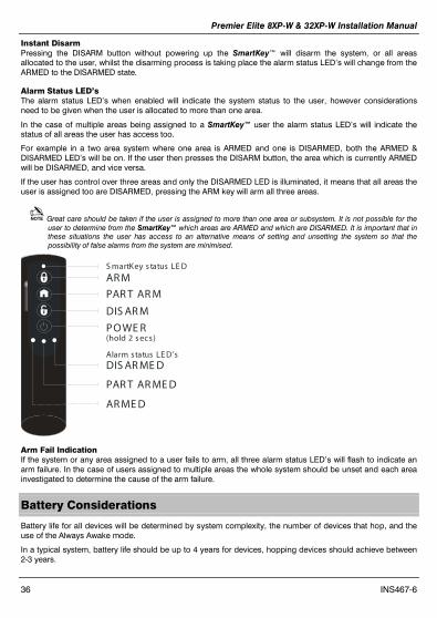
LED Indications SmartKey™ Status LED The Status LED has four colours. This LED cannot be disabled.
1. Pink = Power Up or Down
2. Green = Successful communication with the
system
3. Flashing Blue = communication with system.
4. Red = Out of Range
5. Turquoise = Function Mode
on Premier 412 816 & 832 Function 1 is the Arm Button and Function 2 is the Disarm button.
PA Activation By default PA activation is enabled on the SmartKey™, however the control panel should be programmed to enable Radio PA. Please refer to your Control Panel manual for details.
Enable/Disable Alarm Status LED’s The Alarm Status LED’s can be enabled or disabled either from the Engineers Keypad see page 23, or Ricochet Monitor.
Alarm Status LED’s are not available on the Legacy Premier 412, 816 & 832. For legacy Premier 24/48/88/168 & 640.
Auxiliary Functions The SmartKey™ can also be used to activate auxiliary devices from the control panel outputs. The function keys should first be enabled either from the Engineers Keypad see page 23, or Ricochet Monitor. Once enabled the user can enter Auxiliary mode by pressing the power button when the SmartKey™ is powered up, the status LED will change from blue to turquoise to indicate Function mode.
Once enabled the outputs should be programmed in the control panel to activate the desired function. Please refer to the Control Panel manual for details on how to programme the outputs.
The Function Keys use the PC Control virtual outputs on the control panel and are pre assigned, in the case of the Premier 24/412/816 & 832, only function buttons 1 & 2 may be used.
POWE R
FUNC TION 1/PC C ontrol 1
FUNC TION 3/PC C ontrol 3
FUNC TION 2/PC C ontrol 2
Function S tatus L E D’s
S martKey status LE D
FUNC TION 3
FUNC TION 2
FUNC TION 1
Premier Elite 8XP-W & 32XP-W Installation Manual
36 INS467-6
Instant Disarm Pressing the DISARM button without powering up the SmartKey™ will disarm the system, or all areas allocated to the user, whilst the disarming process is taking place the alarm status LED’s will change from the ARMED to the DISARMED state.
Alarm Status LED’s The alarm status LED’s when enabled will indicate the system status to the user, however considerations need to be given when the user is allocated to more than one area.
In the case of multiple areas being assigned to a SmartKey™ user the alarm status LED’s will indicate the status of all areas the user has access too.
For example in a two area system where one area is ARMED and one is DISARMED, both the ARMED & DISARMED LED’s will be on. If the user then presses the DISARM button, the area which is currently ARMED will be DISARMED, and vice versa.
If the user has control over three areas and only the DISARMED LED is illuminated, it means that all areas the user is assigned too are DISARMED, pressing the ARM key will arm all three areas.
Great care should be taken if the user is assigned to more than one area or subsystem. It is not possible for the user to determine from the SmartKey™ which areas are ARMED and which are DISARMED. It is important that in these situations the user has access to an alternative means of setting and unsetting the system so that the possibility of false alarms from the system are minimised.
(hold 2 s ecs)PO WE R
AR M
DIS AR M
PAR T AR M
Alarm status LE D’s
S martKey s tatus LE D
DIS AR ME D
PAR T AR ME D
AR ME D
Arm Fail Indication If the system or any area assigned to a user fails to arm, all three alarm status LED’s will flash to indicate an arm failure. In the case of users assigned to multiple areas the whole system should be unset and each area investigated to determine the cause of the arm failure.
Battery Considerations
Battery life for all devices will be determined by system complexity, the number of devices that hop, and the use of the Always Awake mode.
In a typical system, battery life should be up to 4 years for devices, hopping devices should achieve between 2-3 years.

Premier Elite 8XP-W & 32XP-W Installation Manual
INS467-6 37
Always Awake. Mode should NOT be used for devices which are subject to multiple activations.
Batteries should only be replaced with an equivalent of those supplied with the devices. Please see the device instructions for details of the correct battery required.
SmartKey™ The SmartKey™ battery should last in excess of five years in normal use. SmartKey™ batteries are NOT replaceable; in the case of a SmartKey™ battery failing the device should be replaced. Please contact your distributor to arrange a replacement.
Low Battery Warning All devices, including SmartKey™ will transmit a Low Battery Warning when there are three months remaining.
Battery Maintenance The system should be checked for low battery warnings at each service interval or a minimum of 12 months whichever is sooner.
Premier Elite 8XP-W & 32XP-W Power Loss
If the power to the receiver is lost for more than one hour, all devices on the system will enter an “Offline” mode to preserve battery life.
When power is replied to the receiver it can take up to two hours for all devices to be recognised by the system.
To resolve this issue quickly each device on the system should be tampered to force communication with the receiver.
The same principles apply to the learning & placing of devices, and as such tampering should start with the device closest to the receiver and working outwards, allowing for the mesh network to be re-established.
Premier Elite 8XP-W & 32XP-W Installation Manual
38 INS467-6
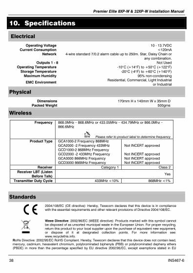
10. Specifications
Electrical
Operating Voltage 10 - 13.7VDC Current Consumption <120mA
Network
4-wire standard 7/0.2 alarm cable up to 250m. Star, Daisy Chain or any combination.
Outputs 1 - 8 Not Used Operating Temperature -10°C (+14°F) to +50°C (+122°F)
Storage Temperature -20°C (-4°F) to +60°C (+140°F) Maximum Humidity 95% non-condensing
EMC Environment Residential, Commercial, Light Industrial
or Industrial
Physical
Dimensions 170mm H x 140mm W x 35mm D Packed Weight 500gms
Wireless
Frequency 868.0MHz – 868.6MHz or 433.05MHz – 434.79MHz or 866.0Mhz –866.6MHz
Please refer to product label to determine frequency Product Type GCA1000-2 Frequency 868MHz
GCA2000 -2 Frequency 433MHz GCD1000-2 868MHz Frequency GCD2000 -2 433MHz Frequency GCA3000 866MHz Frequency GCD3000 866MHz Frequency
Not INCERT approved Not INCERT approved Not INCERT approved Not INCERT approved
Receiver Category 1 Class 2 Receiver LBT (Listen
Before Talk) Yes
Transmitter Duty Cycle 433MHz <10% 868MHz <1%
Standards
2004/108/EC (CE directive): Hereby, Texecom declares that this device is in compliance with the essential requirements and other relevant provisions of Directive 2004/108/EC.
Weee Directive: 2002/96/EC (WEEE directive): Products marked with this symbol cannot be disposed of as unsorted municipal waste in the European Union. For proper recycling, return this product to your local supplier upon the purchase of equivalent new equipment, or dispose of it at designated collection points. For more information see: www.recyclethis.info.
RoHs Directive: 2002/95/EC RoHS Compliant. Hereby, Texecom declares that this device does not contain lead, mercury, cadmium, hexavalent chromium, polybrominated biphenyls (PBB) or polybrominated depheny ethers (PBDE) in more than the percentage specified by EU directive 2002/95/EC, except exemptions stated in EU
Premier Elite 8XP-W & 32XP-W Installation Manual
INS467-6 39
directive 2002/95/EC annex.
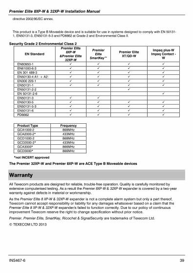
This product is a Type B Moveable device and is suitable for use in systems designed to comply with EN 50131-1, EN50131-3, EN50131-5-3 and PD6662 at Grade 2 and Environmental Class II.
Security Grade 2 Environmental Class 2
EN Standard
Premier Elite 8XP-W
&Premier Elite 32XP-W
Premier Elite
SmartKey™
Premier Elite XT/QD-W
Impaq plus-W Impaq Contact -
W
EN60950-1 EN61000-6-3 EN 301 489-3 EN50130-4 A1: + A2: EN300 220-1 EN50131-1 EN50131-2-2 EN 50131-2-6 EN50131-3 EN50130-5 EN50131-5-3 EN50131-6 PD6662
Product Type Frequency GCA1000-2 868MHz GCA2000-2* 433MHz GCD1000-2 868MHz GCD2000-2* 433MHz GCA3000* 866MHz GCD3000* 866MHz
*not INCERT approved
The Premier 32XP-W and Premier 8XP-W are ACE Type B Moveable devices
Warranty
All Texecom products are designed for reliable, trouble-free operation. Quality is carefully monitored by extensive computerised testing. As a result the Premier 8XP-W & 32XP-W expander is covered by a two-year warranty against defects in material or workmanship.
As the Premier Elite 8 XP-W & 32XP-W expander is not a complete alarm system but only a part thereof, Texecom cannot accept responsibility or liability for any damages whatsoever based on a claim that the Premier Elite 8 XP-W & 32XP-W expander/s failed to function correctly. Due to our policy of continuous improvement Texecom reserve the right to change specification without prior notice.
Premier, Premier Elite, SmartKey, Ricochet & SignalSecurity are trademarks of Texecom Ltd.
© TEXECOM LTD 2013

Texecom Limited, Bradwood Court, St. Crispin Way, Haslingden, Lancashire BB4 4PW, England.
Technical Support: UK Customers Tel: 08456 300 600
(Calls charged at local rate from a BT landline. Calls from other networks may vary.)
International Customers Tel: +44 1706 233875 Email: [email protected]
© Texecom Limited 2013 INS467-6
C er tif ic ate N umbe r : F M 35285