preparation of nio catalyst on fecral substrate using ... · permukaan fecral selepas proses...
TRANSCRIPT
PREPARATION OF NiO CATALYST ON FeCrAl SUBSTRATE USING
VARIOUS TECHNIQUES AT HIGHER OXIDATION PROCESS
YANUANDRI PUTRASARI
A thesis submitted in
fulfillment of the requirement for the award of the
Degree of Master of Mechanical Engineering
Faculty of Mechanical and Manufacturing Engineering
Universiti Tun Hussein Onn Malaysia
JUNE 2011

iv
ABSTRACT
The cheap nickel oxide (NiO) is a potential catalyst candidate to replace the
expensive available platinum group metals (PGM). However, the current methods to
adhere the NiO powder on the metallic substrates are complicated. Therefore, this
work explored the development of nickel oxide using nickel (Ni) on FeCrAl
substrate through the combination of nickel electroplating and oxidation process for
catalytic converter application. The approach was started with assessment of various
nickel electroplating process based on the weight gain during oxidation. Then, the
next experiment used the best process in which the pre-treatment using the solution
of SiC and/or Al2O3 in methanol. The specimens then were carried out to short term
oxidation process using thermo gravimetric analysis (TGA) at 1000 oC. Meanwhile,
the long term oxidation process was conducted using an automatic furnace at 900,
1000 and 1100 oC. The atomic force microscopy (AFM) was used for surface
analysis in nanometer range scale. Meanwhile, roughness test was used for roughness
measurement analysis in micrometer range scale. The scanning electron microscope
(SEM) attached with energy dispersive X-ray (EDX) were used for surface and cross
section morphology analysis. The specimen of FeCrAl treated using ultrasonic prior
to nickel electroplating showed the lowest weight gain during oxidation. The surface
area of specimens increased after ultrasonic treatment. The electroplating process
improved the high temperature oxidation resistance. In short term oxidation process
indicated that the ultrasonic with SiC provided the lower parabolic rate constant (kp)
and the Al2O3 and NiO layers were also occurred. The Ni layer was totally
disappeared and converted to NiO layer on FeCrAl surface after long term oxidation
process. From this work, the ultrasonic treatment prior to nickel electroplating was
the best method to adhere NiO on FeCrAl substrate.

v
ABSTRAK
Nikel teroksida (NiO) yang murah adalah bahan yang berpotensi untuk
menggantikan mangkin PGM yang ada. Namun begitu, kaedah semasa untuk proses
perlekatan NiO pada substrat logam adalah rumit. Oleh sebab itu, kajian ini
menerokai pengembangan nickel oxide menggunakan nickel (Ni) melalui kombinasi
daripada nickel electroplating dan proses pengoksidaan. Pendekatan ini dimulakan
dengan kajian pada pelbagai nickel electroplating process merujuk pada perubahan
berat semasa pengoksidaan. Kemudian percubaan selanjutnya menggunakan proses
yang terbaik iaitu rawatan awal menggunakan larutan SiC dan/atau Al2O3 dalam
methanol. Specimen kemudian diperlakukan pada proses pengoksidaan jangkamasa
pendek dengan menggunakan TGA pada 1000 oC. Sementara itu proses
pengoksidaan jangkamasa panjang pada spesimen dilakukan dengan menggunakan
furnace automatik di 900, 1000 dan 1100 oC. Spesimen dianalisis pada pembesaran
oksida, morfologi permukaan dan penampang. AFM digunakan untuk analisis
permukaan dalam skala nanometer. Sementara itu, alat ukur kekasaran digunakan
untuk menganalisis pengukuran kekasaran dalam skala mikrometer. SEM disertakan
dengan EDX digunakan untuk analisis permukaan dan morfologi lintang. Spesimen
daripada FeCrAl dirawat menggunakan ultrasonic sebelum nickel electroplating
menunjukkan perubahan berat terkecil selama masa pengoksidaan. Luas permukaan
spesimen semakin meningkat selepas rawatan ultrasonik. Proses electroplating
membaiki ketahanan pengoksidaan suhu tinggi. Pada proses pengoksidaan
jangkamasa pendek menunjukkan bahawa ultrasonic dengan SiC menyediakan
parabolic rate constant (kp) yang lebih rendah dan lapisan Al2O3 dan NiO juga telah
wujud. Lapisan Ni telah tiada dan mengalami perubahan menjadi lapisan NiO pada
permukaan FeCrAl selepas proses pengoksidaan jangkamasa panjang. Daripada
penyelidikan ini, rawatan ultrasonik sebelum proses electroplating merupakan
kaedah terbaik untuk melekatkan NiO pada substrat FeCrAl.
vi
CONTENTS
TITLE
i
DECLARATION
ii
ACKNOWLEDGEMENT
iii
ABSTRACT
iv
CONTENTS
vi
LIST OF TABLES
x
LIST OF FIGURES
xi
LIST OF SYMBOLS AND ABBREVIATIONS
xv
LIST OF APPENDICES xviii
CHAPTER 1 INTRODUCTION 1
1.1 Research background
1
1.2 Problem statement
3
1.3 Hypotheses
3

vii
1.4 Research objectives
4
1.5 Research scopes 4
CHAPTER 2 LITERATURE REVIEW 5
2.1 Catalytic converter components and its preparation
5
2.1.1 Substrate
5
2.1.2 Washcoat
8
2.1.3 Catalyst
11
2.2 Nickel electroplating
14
2.3 Ultrasonic treatment
18
2.4 Development of oxide layer using a high
temperature oxidation process
20
CHAPTER 3 METHODOLOGY 22
3.1 Materials
22
3.2 First step: assessment of FeCrAl treated using
various nickel electroplating process
24
3.2.1 Nickel electroplating
25
3.2.2 Ultrasonic prior to, during, and after nickel
electroplating
26

viii
3.2.3 Nickel electroplating using electrolyte modification
27
3.2.6 Oxidation process
28
3.3 Second step: short term oxidation process
29
3.4 Third step: long term oxidation process
31
CHAPTER 4 RESULTS AND DISCUSSIONS 33
4.1 Assessment of FeCrAl treated using various nickel
electroplating process based on the weight gain
33
4.2 Analysis of FeCrAl for short term oxidation
36
4.2.1 Surface analysis
36
4.2.2 The effect of ultrasonic treatment with SiC or Al2O3
prior to nickel electroplating on weight gain
41
4.2.3 Parabolic rate constant
43
4.2.4 Cross section analysis of Al2O3 and NiO layers
44
4.2.5 Surface analysis of Al2O3 layer
50
4.3 Analysis of Al2O3 and NiO layers after long term
oxidation
54
4.3.1 Influence of various pre-treatment times and
temperatures on weight gain and parabolic rate
constant
54
4.3.2 Cross section analysis
63

ix
CHAPTER 5 CONCLUSIONS AND RECOMMENDATIONS 73
5.1 Research conclusions
73
5.2 Recommendations for the future works 74
REFERENCES 75
APPENDICES 84
VITA

x
LIST OF TABLES
2.1 Time to electrodeposits nickel at various current densities 16
2.2 Formula and operating conditions for Watts nickel electroplating
solutions
16
3.1 Chemical compositions Aluchrom Yhf (wt-%) 24
3.2 General properties of nickel 24
3.3 Electrolyte solution compositions 24
3.4 The condition of electroplating process 26
4.1 Mean roughness of FeCrAl surface 37
4.2 Parabolic rate constants for FeCrAl substrate pre-treated with SiC
or Al2O3 at 1000 oC
44
4.3 Parabolic rate constant (kp) of FeCrAl treated using ultrasonic and
electroplating methods and oxidized at 900 oC
57
4.4 Parabolic rate constant (kp) of FeCrAl treated using ultrasonic and
electroplating methods and oxidized at 1000 oC
59
4.5 Parabolic rate constant (kp) of FeCrAl treated using ultrasonic and
electroplating methods and oxidized at 1100 oC
62

xi
LIST OF FIGURES
1.1 Catalytic converter components 2
2.1 Comparison of thermogravimetric oxidation of austenitic and
aluminium containing ferritic steels showing weight gain at 1200 oC due to surface oxidation as a function time
7
2.2 Scanning electron microscopy images showing the surface of
austenictic and aluminium-containing ferritic steels after heat
treatment in air
7
2.3 Scanning electron micrograph of a ceramic monolith with square
shaped a cell that has been coated with washcoat catalyst
8
2.4 Conceptual model for catalytic sites dispersed on high surface area
Al2O3 carrier bonded to a monolith
9
2.5 SEM image of washcoat and catalyst on FeCrAl substrate 9
2.6 Basic electrical for electroplating 15
2.7 Position of electrodes and ultrasonic vibrator 17
2.8 The shock-wave mechanism and micro-jet mechanism of
cavitation erosion
19
2.9 Material loss due to cavitation erosion with different oil types 19
3.1 Flow chart of the research 23
3.2 Electroplating process 26
3.3 Schematic diagram of ultrasonic prior to, after and during
electroplating
27
3.4 Cyclic approach testing program 29
4.1 Effect of various electroplating process on weight gain vs time of
FeCrAl during oxidation at 900 oC
35
4.2 Roughness profile of FeCrAl surface. 37
4.3 Roughness 3D images of FeCrAl surface 39

xii
4.4 Grain area image of FeCrAl surface 40
4.5 Effect of ultrasonic treatment with SiC or Al2O3 prior to nickel
electroplating on weight gain of FeCrAl during short term
oxidation
42
4.6 Effect of ultrasonic treatment with SiC or Al2O3 prior to nickel
electroplating on significant weight gain of FeCrAl at temperature
higher than 900 oC
43
4.7 ( )AW 2∆ vs time plotted for oxidation of FeCrAl pre-treatment using
ultrasonic prior to nickel electroplating 1) with SiC, and 2) with Al2O3
44
4.8 Cross section scanning micrograph showing four layers of FeCrAl
pre-treatment using ultrasonic with SiC and Al2O3 prior to nickel
electroplating after short term oxidation
45
4.9 Cross section scanning micrograph and EDX elemental mapping
of Al2O3 layer on the cross section of FeCrAl pre-treated with SiC.
46
4.10 Cross section scanning micrograph and EDX elemental mapping
of Al2O3 layer on the cross section of FeCrAl pre-treated with
Al2O3
47
4.11 SEM image of the morphology of the cross section of FeCrAl pre-
treated with SiC
48
4.12 SEM image of the morphology of the cross section of FeCrAl pre-
treated with Al2O3
49
4.13 SEM image on the cross section of FeCrAl treated with SiC, Ni
mapping, and O2 mapping
49
4.14 SEM image on the cross section of FeCrAl treated with Al2O3, Ni
mapping, and O2 mapping
50
4.15 Surface images of alumina whiskers which formed on the FeCrAl
untreated after oxidation at 900 oC for 20 hours
51
4.16 Surface images of alumina whiskers which formed on the FeCrAl
pre-treated with SiC after oxidation at 900 oC for 20 hours
52
4.17 Suface images of alumina granules which formed on the FeCrAl
untreated after oxidation at 1100 oC for 20 hours
53
4.18 Suface images of alumina granules which formed on the FeCrAl
pre-treated with SiC after oxidation at 1100 oC for 20 hours
54
xiii
4.19 Influence of various pre-treatment times on weight gain of FeCrAl
treated using ultrasonic with SiC, and with Al2O3 prior to nickel
electroplating during oxidation at 900 oC using cyclic approach
56
4.20 Influence of various pre-treatment times on weight gain of FeCrAl
treated using ultrasonic with SiC, and with Al2O3 prior to nickel
electroplating during oxidation at 1000 oC using cyclic approach
58
4.21 Influence of various pre-treatment times on weight gain of FeCrAl
treated using ultrasonic with SiC, and with Al2O3 prior to nickel
electroplating during oxidation at 1100 oC using cyclic approach
61
4.22 Cross section scanning electron micrograph of FeCrAl treated with
SiC for 10 minutes after oxidation at 900 oC
64
4.23 Cross section scanning electron micrograph of FeCrAl treated with
Al2O3 for 30 minutes after oxidation at 900 oC
65
4.24 Cross section scanning electron micrograph showing EDX line
analysis of FeCrAl ultrasonic with SiC for 10 minutes, and Al2O3
for 30 minutes prior to nickel electroplating and oxidized at 900 oC
with its chemical's intensity graph
67
4.25 Cross section scanning electron micrograph of FeCrAl ultrasonic
treatment with SiC 50 minutes, and 20 minutes prior to nickel
electroplating after oxidation at 1000 oC
68
4.26 Cross section scanning electron micrograph of FeCrAl ultrasonic
treatment with Al2O3 20 minutes, and 40 minutes prior to nickel
electroplating after oxidation at 1000 oC
68
4.27 Cross section scanning electron micrograph showing EDX line
analysis of FeCrAl ultrasonic with SiC for 10 minutes, and Al2O3
for 30 minutes prior to nickel electroplating and oxidized at 1000 oC with its chemical's intensity graph
69
4.28 Cross section scanning electron micrograph of FeCrAl ultrasonic
treatment with SiC 10 minutes, and 30 minutes prior to nickel
electroplating after oxidation at 1100 oC
70
4.29 Cross section scanning electron micrograph of FeCrAl ultrasonic
treatment with Al2O3 20 minutes, and 50 minutes prior to nickel
electroplating after oxidation at 1100 oC
71

xiv
4.30 Cross section scanning electron micrograph showing EDX line
analysis of FeCrAl ultrasonic with SiC for 30 minutes, and Al2O3
for 30 minutes prior to nickel electroplating, and oxidized at 1100 oC with its chemical's intensity graph
72
xv
LIST OF SYMBOLS AND ABBREVIATIONS
Al - Aluminium
Al(OH)3 - Aluminium Hydroxide
Al2O3 - Aluminium Oxide/ Alumina
AlCl3 - Aluminium Trichloride
AlOOH - Aluminium Oxide Hydroxide
AMO3 - 3rd-Transition Metal Perovskite
At% - Atomic Percentage
C2H6 - Ethane
Ce - Cerium
CeO2 - Ceria
CH4 - Methane
CO - Carbon Monoxide
CO2 - Carbon Dioxide
Cr - Chromium
Cr2O3 - Chromia
Cu - Cuprum
Fe - Ferum/Iron
Fe2O3 - Iron Oxide
FeCrAl - Ferro Chrom Aluminium
h - Hour
H2 - Hydrogen
H2O - Water
H3BO3 - Boric Acid
HC - Hydrocarbon
Hf - Hafnium
kp - Kinetic Parabolic Rate
La - Lanthanum
xvi
Mg - Magnesium
Mn - Manganese
N2 - Nitrogen
Ni - Nickel
Ni(NO3)2.xH2O - Nickel (II) Nitrite
NiAl2O4 - Nickel Alumina
NiCl2.6H2O - Nickel Chloride
NiO - Nickel Oxide
NiSO4 - Nickel Sulphate
[Ni(NH2SO3)2.4H2O)] - Nickel Sulphamate
NOx - Nitrogen Oxide
O2 - Oxygen
Pd - Palladium
Pt - Platinum
Rh - Rhodium
SiC - Silicone Carbide
SiO2 - Silicon Oxide
Ti - Titanium
TiO2 - Titanium Dioxide
WO4 - Tungsten Oxide
Wt% - Weight Percentage
Y - Yttrium
Y2O3 - Yttria
Zr - Zirconium
γ - Gamma
µm - Micrometer
AFM - Atomic Force Microscopy
ASTM - American Society for Testing and Materials
BATAN - Badan Tenaga Nuklir Nasional (National
Nuclear Energy Agency of Indonesia)
BES - Back Scattered Mode
dm - Decimetre
EDX - Energy Dispersive X-ray
HIWI - Hot Incipient Wetness Impregnation
xvii
kHz - Kilohertz
MA - Mechanical Alloying
mg - Milligram
MHz - Megahertz
mm - Millimetre
OSC - Oxygen Storage Capacity
PGM - Platinum Group of Metals
SEM - Scanning Electron Microscopy
STEM - Scanning Transmission Electron Microscope
TGA - Thermo Gravimetric Analysis
TPR-MS - Temperature-Programmed Reaction Mass
Spectroscopy
TWC - Three Way Catalyst
UTHM - University Tun Hussein Onn Malaysia
XRD - X Ray Diffraction

xviii
LIST OF APPENDICES
APPENDIX TITLE PAGE
A Atomic Force Microscopy Analysis 84
B Particle Size Distribution Analysis 91
C The Calculation of Total Grain Area of Substrate 93
D Surface Morphology of FeCrAl after Pre-treatment
and Its Chemical Composition Using SEM with
EDX
95
E Data of Thermo Gravimetric Analysis 99
F Roughness Test Using Mitutoyo SJ-400 103
G Data of Cyclic Oxidation Test 106
H List of Papers 107

CHAPTER 1
INTRODUCTION 1.1 Research background Four ASEAN countries namely Indonesia, Malaysia, Philippines, and Thailand are
facing major air pollution problems due to rapid economic growth, urbanization and
motorization. Mortality and respiratory diseases caused by air pollution are believed
to be endemic in cities of these countries. Regulations and standards are the first
requirement for reducing emissions from both fixed and mobile sources. In order to
reduce vehicle emissions, governments of the four countries are making efforts to
introduce vehicle emission regulations for new vehicles. The common target is the
introduction of EURO 2 standard by 2008 and EURO 4 standard by 2012. In order
to abide the EURO 2 standard level, it is necessary to install catalytic converters to
meet the emission regulation level (CO, HC, NOx, etc.) (Hirota, 2009).
Sudrajad (2005) mentions that the technology of vehicle emission reduction
can be categorized into two major parts, namely primary and secondary method. For
the primary method, it depends on fuel, on air treatment, and on a combustion
process. Meanwhile, the secondary method is the use of a catalytic converter in the
exhaust system of vehicles.
Catalytic converter is a device incorporated into the exhaust system of an
automobile that reduces the amount of nitrogen oxides, carbon monoxide, and un-
reacted hydrocarbons in automotive emissions (Sebayang et al., 2006). A catalytic
converter as shown in Figure 1.1 consists of an insulated chamber (casing)
containing a porous bed (substrate and washcoat), coated with catalyst material in
which the exhaust gas must pass through before being discharged into the air
(Searles, 2002). The catalytic material is used as a trigger to reduce or oxidize

2
reaction of HC, CO and NO, to reduce the amount of harmful products, i.e. H2O,
CO2, N2 and O2 (Sebayang et al., 2007)
Figure 1.1: Catalytic converter components. a) substrate, b) washcoat, c) catalysts, d) casing (Searles, 2002)
There are many problems in the forming and manufacturing of the catalytic
converter. Koltsakis & Stamatelos (1997) explains that the catalyst for catalytic
converter is mostly related to the precious group of metals (PGM's) platinum,
palladium, and rhodium. However, due to regulations, these materials are expensive
and limited in developing countries, like in Malaysia. This is overcome by using
nickel as a catalyst to replace the function of these precious groups of metals.
Therefore, the utilization of nickel is investigated in this research.
The other challenge from the utilization of nickel as catalyst and FeCrAl as a
substrate in catalytic converter manufacturing is the washcoat development. The
washcoat is a kind of ceramic layer (oxide layer) which has specific surface area and
acts as support for catalyst materials. The waschoat also acts as a barrier from high
temperature corrosion (Cueff et al., 2004).
This work investigates the new method to develop washcoat, to adhere nickel
on the FeCrAl substrate, and to convert the nickel to be nickel oxide. The proposed
method is coating technique using a combination of a nickel electroplating,
ultrasonic treatment and oxidation process.
d
c
b
a
3
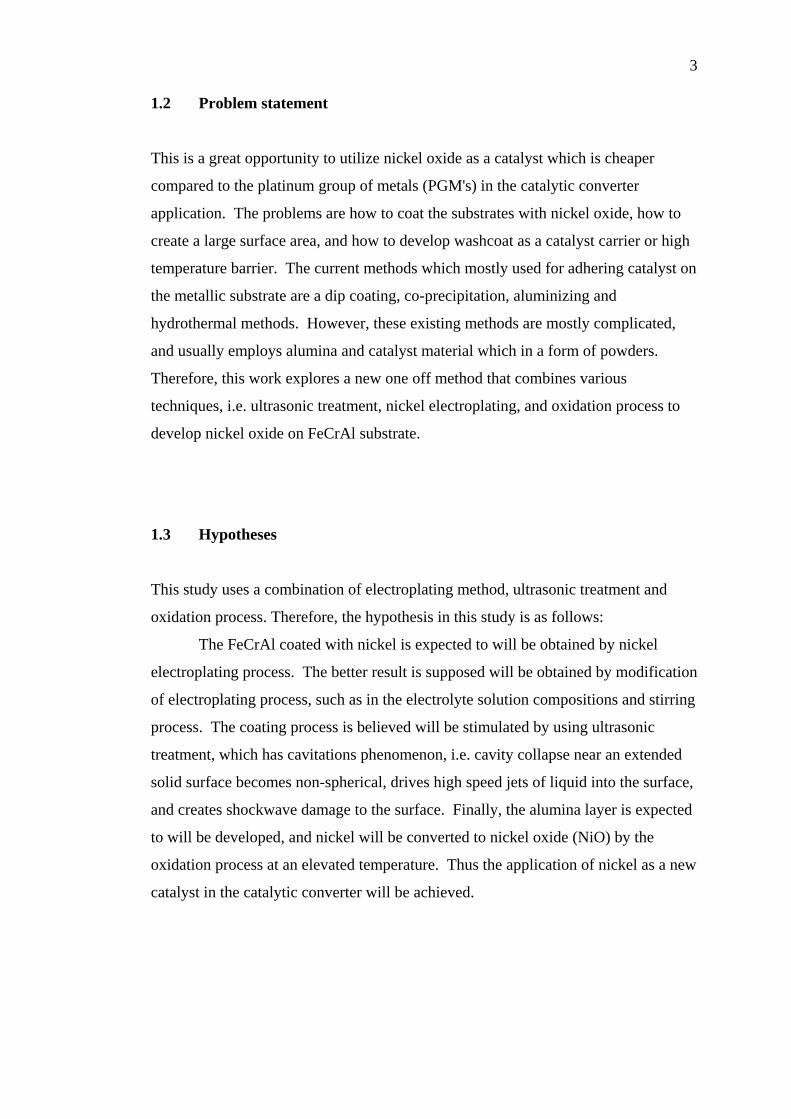
1.2 Problem statement This is a great opportunity to utilize nickel oxide as a catalyst which is cheaper
compared to the platinum group of metals (PGM's) in the catalytic converter
application. The problems are how to coat the substrates with nickel oxide, how to
create a large surface area, and how to develop washcoat as a catalyst carrier or high
temperature barrier. The current methods which mostly used for adhering catalyst on
the metallic substrate are a dip coating, co-precipitation, aluminizing and
hydrothermal methods. However, these existing methods are mostly complicated,
and usually employs alumina and catalyst material which in a form of powders.
Therefore, this work explores a new one off method that combines various
techniques, i.e. ultrasonic treatment, nickel electroplating, and oxidation process to
develop nickel oxide on FeCrAl substrate.
1.3 Hypotheses This study uses a combination of electroplating method, ultrasonic treatment and
oxidation process. Therefore, the hypothesis in this study is as follows:
The FeCrAl coated with nickel is expected to will be obtained by nickel
electroplating process. The better result is supposed will be obtained by modification
of electroplating process, such as in the electrolyte solution compositions and stirring
process. The coating process is believed will be stimulated by using ultrasonic
treatment, which has cavitations phenomenon, i.e. cavity collapse near an extended
solid surface becomes non-spherical, drives high speed jets of liquid into the surface,
and creates shockwave damage to the surface. Finally, the alumina layer is expected
to will be developed, and nickel will be converted to nickel oxide (NiO) by the
oxidation process at an elevated temperature. Thus the application of nickel as a new
catalyst in the catalytic converter will be achieved.

4
1.4 Research objectives The objectives of this research are as follows:
(i) To develop NiO catalyst layer, Al2O3 layer, and high surface area on FeCrAl
substrate.
(ii) To investigate the effect of ultrasonic treatment and nickel electroplating on
high temperature oxidation behaviour of the FeCrAl for six hours and 100
hours.
1.5 Research scopes The scope of this research includes:
(i) The investigation on the various electroplating techniques of nickel on
FeCrAl metallic monolith.
(ii) The investigation on the modification of surface roughness and area, and the
effect of ultrasonic treatment on six hours high temperature oxidation
behaviour of the FeCrAl.
(iii) The investigation on nickel oxide developed as a catalyst on FeCrAl substrate
using ultrasonic, nickel electroplating, and oxidation process methods.
(iv) The investigation on high temperature oxidation behaviour of FeCrAl
substrate treated using ultrasonic and nickel electroplating methods at the
temperature of working condition of the catalytic converter for 100-hours
oxidation processes.

CHAPTER 2
LITERATURE REVIEW This chapter presents the theoretical background and previous work by the
researchers on catalytic converter components and its preparation methods. The
ultrasonic treatment, nickel electroplating, and oxidation process are also
highlighted.
2.1 Catalytic converter components and its preparation A catalytic converter consists of four basic components, i.e. substrate, washcoat,
catalyst, and casing (Sebayang et al., 2009; Searles, 2002). Substrate, washcoat, and
catalyst are the most interesting topic which usually discussed by many researchers.
Therefore, these three components discussed in this chapter.
2.1.1 Substrate Substrate is a support, on which the catalyst is deposited, and therefore, it is often
called a "catalyst support". Gulati (2006) explains that the substrate is an integral
part of a catalytic converter system that has a primary function to bring the maximum
active catalyst. It must withstand a variety of severe operating conditions, namely
rapid changes in temperature, gas pulsations from the engine, chassis vibrations, and
road shocks. It supports the catalyst used in an exhaust of a combustion chamber in
order to meet the demand for low pressure drop (Ersson & Järås, 2006).

6
In order to accommodate the catalyst in significant amounts, substrate must
be provided with a high surface area. Twigg & Webster (2006) suggests that the
design of substrate must provide a maximum surface area. The catalyst coating is
applied on this surface area and on which the pollutant gases must impinge in order
to react.
Ferritic steel (FeCrAl) is the famous metallic material for catalytic converter
substrate. The FeCrAl selected as the substrate due to the high temperature oxidation
resistance. Metal supported automotive catalytic converter bodies according to
Nicholls & Quadakkers (2002) are based on ferritic steels with 5-8wt% aluminium,
17-22wt% chromium, plus small additions of reactive elements. These elements
added to improve the oxidation resistance of the alloy and oxide adhesion. These
alloys are protected by the formation of a slow growing surface oxide, usually
alumina. It is critical to component life if naturally formed alumina protective layer
is maintained (Klower, et al., 1998).
Twigg & Webster (2006) explains that the advantage of ferritic steels lies not
only in their resistance to corrosion, but when appropriately treated they have
strongly adhering oxide film on their surface. This material if heated to 300-400 oC,
the surface oxide film which is chromina rich developed. However, at temperatures
above 800 oC an alumina-rich surface is developed, which endows the steel with
excellent high temperature resistance. In distinction, austenitic steels, which also
have good high-temperature resistance (Figure 2.1), develop an iron-rich surface
layer which at high temperatures tends to flake off, or "spall," as shown in Figure
2.2.

7
Figure 2.1: Comparison of thermo gravimetric oxidation of austenitic (upper curve) and aluminium-containing ferritic steels (lower curve) showing weight gain at 1200
oC due to surface oxidation as a function of time (Twigg & Webster, 2006)
(a) (b)
Figure 2.2: Scanning electron microscopy images showing the surface of (a) austenitic and (b) aluminium-containing ferritic steels after heat treatment in air (Twigg & Webster, 2006)
Some methods are necessary to improve the surface area for the substrate
(Twigg & Webster, 2006). The previous effort on developing high surface area of
metallic substrate is to conduct a simulation to obtain an optimal geometry and create

8
an innovative tool to produce a spiral corrugated foil with length 150 cm, width 100
cm and the thickness 0,11 mm, 0, 065 and 0, 045 mm (Sebayang et al., 2009).
2.1.2 Washcoat Washcoat is a kind of oxide material which developed on the substrate to improve
adhesion of the catalyst onto the substrate. The washcoat is a thin layer of alumina
(Al2O3) coating, typically 20-150 µm thick with a high surface area on the top of
substrate. The surface of monolith support needs to be coated with a layer of high
surface area material, commonly known as washcoat, in which the catalyst is
dispersed (Hayes & Kolaczkowski, 1997). Heck, Farrauto, & Gulati (2002), explains
that a washcoat as the catalyst's carrier. Several examples of a high surface area
carrier are Al2O3, SiO2, TiO2, and SiO2-Al2O3. Alumina (Al2O3) is one of the most
applied washcoat materials (Xu & Moulijn, 2006; Heck, et al., 2009). Figure 2.3
shows the scanning electron micrograph of ceramic monolith with square shaped
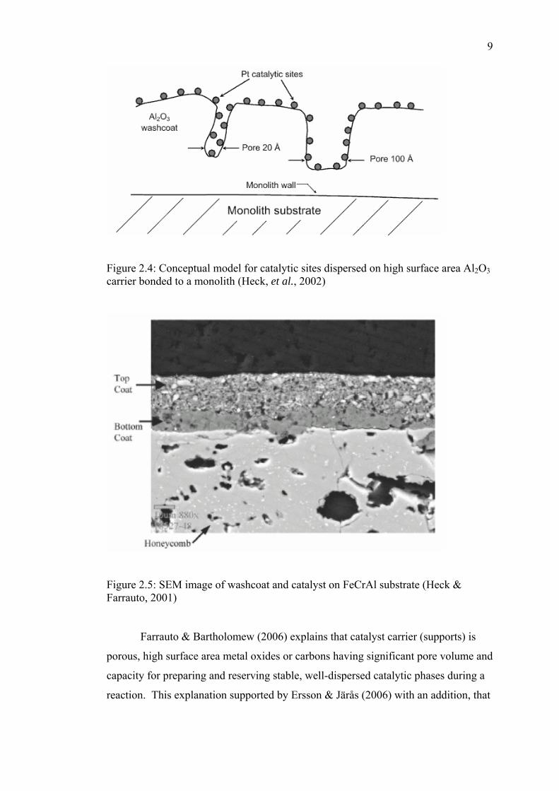
cells that has been coated with washcoat and catalyst. Figure 2.4 illustrates a few
select pores of a high surface area Al2O3 as the most commonly used carrier in
catalysis. Figure 2.5 presents the cross section image of washcoat and catalyst on
FeCrAl substrate (honeycomb).
Figure 2.3: Scanning electron micrograph of a ceramic monolith with square shaped a cell that has been coated with washcoat catalyst (Hayes & Kolaczkowski, 1997)
9
Figure 2.4: Conceptual model for catalytic sites dispersed on high surface area Al2O3 carrier bonded to a monolith (Heck, et al., 2002)
Figure 2.5: SEM image of washcoat and catalyst on FeCrAl substrate (Heck & Farrauto, 2001)
Farrauto & Bartholomew (2006) explains that catalyst carrier (supports) is
porous, high surface area metal oxides or carbons having significant pore volume and
capacity for preparing and reserving stable, well-dispersed catalytic phases during a
reaction. This explanation supported by Ersson & Järås (2006) with an addition, that

10
washcoat has to remain unchanged during the extended operation of the catalyst at
temperatures between 1000 and 1400 oC.
Xu & Moulijn (2006) expresses that, in principle, the surface area of
monolith substrate is low. The various techniques can be used to coat an oxides
layer a monolith. The alumina washcoating is the most widely used technique for
monolith. The reason is that alumina has resistance to high temperature and other
advantages over other oxide materials.
A study conducted by Anderson & García (2005) for a classical three way
catalyst (TWC) formulation was established, using a mixture of Pt and Rh in
typically 5:1 weight ratio as a precious metal catalyst, and cerium oxide as an oxygen
buffer. All these ingredients were dispersed on a layer of porous alumina (the
"washcoat"), possibly stabilized against sintering with appropriate additives and
itself deposited on a metallic or ceramic honeycomb-type rigid structure.
A conventional washcoating technique for production catalytic monolith
products generally comprise preparing a coating formed from a high surface area
oxide blended with one or more catalysts and dipping the monolith structure into that
coating blend (Huang & Bar-Ilan, 2002). In utilization for automotive converters the
catalyst comprises one or more noble metals, such as platinum, palladium and
rhodium. These noble metals are blended with high surface area metal oxides such
as alumina or ceria. These washcoat are then coated upon monolithic support
structures, such as ceramics honeycombs supports. Similar with Huang & Bar-Ilan
(2002), Eleta et al. (2010) uses also washcoating technique by dipping method.
According to Zhao et al. (2003), the coating adhesion between the metallic
support and the ceramic washcoat become a problem, so that, a widely used method
to coat ceramics on metallic support is the dip coating. To compensate the intrinsic
disadvantages of this method, some pre-treatment method e.g. develop a technique to
grow a number of textured alumina whiskers on the surface of the metal support
before dip coating and shortened the diffusion path before depositing the washcoat
both of them expected greatly improved the combination ability between the
alumina washcoat and the support.
The dip coating method for developing washcoat on a metallic substrate with
pre-treatment method similar with Zao et al. (2003), was also conducted by Jia, Shen
& Wang (2007). Meanwhile, the co-precipitation, sol-gel and spray-pyrolysis
11
methods were also applied for preparation of FeCrAlloy supported perovskite (a kind
of washcoat) for catalytic combustion of methane (Yanqing et al., 2010).
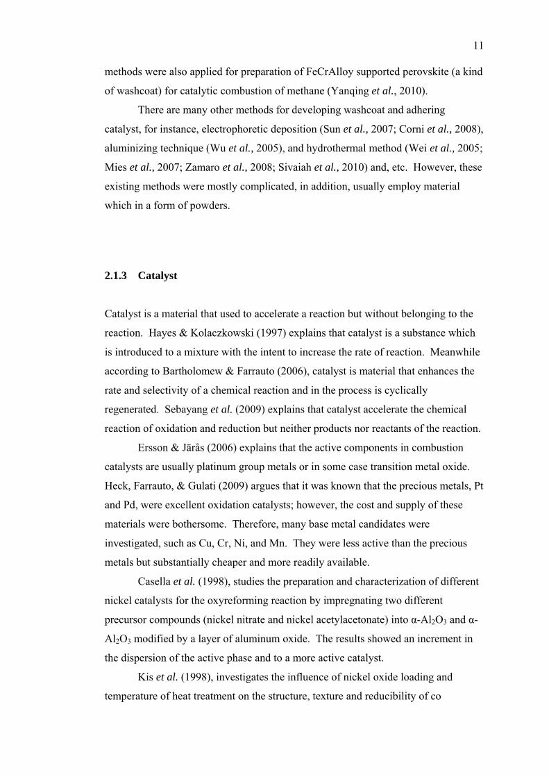
There are many other methods for developing washcoat and adhering
catalyst, for instance, electrophoretic deposition (Sun et al., 2007; Corni et al., 2008),
aluminizing technique (Wu et al., 2005), and hydrothermal method (Wei et al., 2005;
Mies et al., 2007; Zamaro et al., 2008; Sivaiah et al., 2010) and, etc. However, these
existing methods were mostly complicated, in addition, usually employ material
which in a form of powders.
2.1.3 Catalyst Catalyst is a material that used to accelerate a reaction but without belonging to the
reaction. Hayes & Kolaczkowski (1997) explains that catalyst is a substance which
is introduced to a mixture with the intent to increase the rate of reaction. Meanwhile
according to Bartholomew & Farrauto (2006), catalyst is material that enhances the
rate and selectivity of a chemical reaction and in the process is cyclically
regenerated. Sebayang et al. (2009) explains that catalyst accelerate the chemical
reaction of oxidation and reduction but neither products nor reactants of the reaction.
Ersson & Järås (2006) explains that the active components in combustion
catalysts are usually platinum group metals or in some case transition metal oxide.
Heck, Farrauto, & Gulati (2009) argues that it was known that the precious metals, Pt
and Pd, were excellent oxidation catalysts; however, the cost and supply of these
materials were bothersome. Therefore, many base metal candidates were
investigated, such as Cu, Cr, Ni, and Mn. They were less active than the precious
metals but substantially cheaper and more readily available.
Casella et al. (1998), studies the preparation and characterization of different
nickel catalysts for the oxyreforming reaction by impregnating two different
precursor compounds (nickel nitrate and nickel acetylacetonate) into α-Al2O3 and α-
Al2O3 modified by a layer of aluminum oxide. The results showed an increment in
the dispersion of the active phase and to a more active catalyst.
Kis et al. (1998), investigates the influence of nickel oxide loading and
temperature of heat treatment on the structure, texture and reducibility of co

12
precipitated NiO-A12O3 catalyst. The results show that the interactions in co
precipitated NiO-Al2O3 system are intensive.
Raney type catalysts by means of a two-step procedure: i) mechanical
alloying (MA) of the metals and ii) alkaline aluminum leaching is prepared by
Zeifert et al. (2000). It is concluded that MA is a novel alternative related to the
synthesis of skeletal Ni catalysts.
Quintana-Melgoza, Gómez-Cortés & Avalos-Borja (2002) compares NiWO4,
NiO, and WO3 catalysts for simultaneous conversion of NO and CO. Samples is
synthesized by reacting ammonium metatungstaten and/or nickel nitrate at a high
temperature (773 to 903 K) under an oxygen stream. The catalytic reduction of NO
by CO takes place in the temperature range (523 to 973 K) under highly reductive
conditions (NO:CO = 1:5) over NiWO4, NiO, and WO3, respectively. In the range
(523 to 723 K) NiO is more active than NiWO4 and WO3 catalysts.
Xiang et al. (2004), develops an advanced hydrothermal modification method
to synthesis Ni/Al2O3 catalyst with perfect activity. The experimental results
indicate that the modification of the impregnation samples at elevated temperatures
enhanced the absorption of Ni(NO3)2.xH2O on the surface of supporters which is
composed mainly of Al(OH)3 and AlOOH, leading to the formation of the porous
sintering products (NiAl2O4/Al2O3) with bigger specific surface areas and higher Ni
contents. The conversion of CH4 increases a lot by using the hydrothermal-modified
catalyst instead of using the catalyst prepared via the traditional impregnation–
sintering route.
The use of Ni as a catalyst for the electro-oxidation of methanol in an alkaline
medium is studied by cyclic voltammetry (Abdel Rahim et al., 2004). Ni is
dispersed on graphite by the electro-deposition from acidic NiSO4 solution using
potentiostatic and galvanostatic techniques. It is concluded from the electro-
chemical measurements and SEM analysis that methanol oxidation starts as Ni-oxide
is formed on the electrode surface.
Fonseca & Assaf (2005) prepares nickel catalysts from hydrotalcite
precursors, characterizes and tests in the reaction of methane steam reforming to
produce hydrogen. The precursors are synthesized by the traditional technique, with
co-precipitation of Ni, Mg and Al nitrates with carbonate; coprecipitation of Mg and
Al nitrates with pre-synthesized nickel chelate and anion-exchange of NO3− of
hydrotalcite with nickel chelate. The catalytic tests demonstrate high methane

13
conversion, high activity for hydrogen production and high stability during the time
of reaction for a molar ratio in the feed H2O:CH4 = 2:1.
A catalyst configuration comprises: a substrate, a NiO layer was disposed on
the substrate, and a catalyst layer comprising a NOx adsorbing catalyst was patented
by Dou (2005). The method is making a NOx absorber by thermally treating NiO to
a temperature of about a maximum catalyst application temperature minus 100 oC
and the maximum catalyst application temperature.
Ochoa et al. (2007) prepares a series of hydrotalcite-like catalysts (HT) with
different Ni loadings by a co-precipitation technique and compared with catalysts
prepared by conventional incipient wetness impregnation. The co-precipitation route
results in a stronger interaction between the support and nickel than the incipient
wetness route.
Xiancai et al. (2008) prepares the nickel-based catalysts by the sol-gel
method and used for the CH4 reforming with CO2. Compared with the catalyst
prepared by the impregnation method, the results indicated that the catalysts prepared
by the sol-gel method had larger specific surface area, showing higher catalytic
activities and exhibiting perfect desorption and reduction performances.
Jang et al. (2008) studies the characterization of Al2O3 supported Ni catalysts
derived from the RF non-thermal plasma technique with in-situ XRD, TPR-MS and
STEM and on relating the results to the enhanced activity and stability of benzene
hydrogenation. The results suggest that catalysts with plasma treatments before
impregnation are relatively easier to be reduced and result in better activities under
mild reduction conditions. The catalyst with a combination plasma treatment
demonstrates that the effect of a combination plasma treatment is larger than either
the plasma treatment before or after the impregnation alone.
Shi & Liu (2009) applies the room temperature glow discharge plasma to
treat the nickel precursor supported on SiO2. According to the catalyst
characterization, the calcinations thermally of the plasma treated sample show a
small particle size and high dispersion. Such prepared sample presents high
conversions of carbon monoxide and hydrogen for the reaction of methanation with a
significantly improved anticarbon deposition performance. The plasma-treated
sample shows enhanced metal-support interaction and keeps good dispersion after
reaction.
14
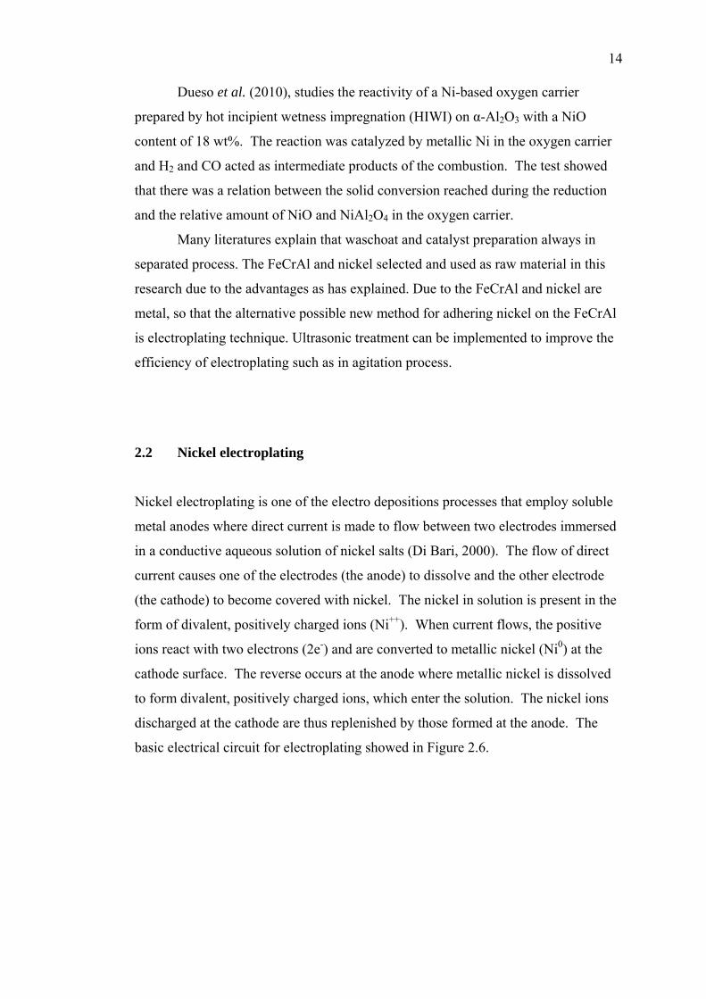
Dueso et al. (2010), studies the reactivity of a Ni-based oxygen carrier
prepared by hot incipient wetness impregnation (HIWI) on α-Al2O3 with a NiO
content of 18 wt%. The reaction was catalyzed by metallic Ni in the oxygen carrier
and H2 and CO acted as intermediate products of the combustion. The test showed
that there was a relation between the solid conversion reached during the reduction
and the relative amount of NiO and NiAl2O4 in the oxygen carrier.
Many literatures explain that waschoat and catalyst preparation always in
separated process. The FeCrAl and nickel selected and used as raw material in this
research due to the advantages as has explained. Due to the FeCrAl and nickel are
metal, so that the alternative possible new method for adhering nickel on the FeCrAl
is electroplating technique. Ultrasonic treatment can be implemented to improve the
efficiency of electroplating such as in agitation process.
2.2 Nickel electroplating Nickel electroplating is one of the electro depositions processes that employ soluble
metal anodes where direct current is made to flow between two electrodes immersed
in a conductive aqueous solution of nickel salts (Di Bari, 2000). The flow of direct
current causes one of the electrodes (the anode) to dissolve and the other electrode
(the cathode) to become covered with nickel. The nickel in solution is present in the
form of divalent, positively charged ions (Ni++). When current flows, the positive
ions react with two electrons (2e-) and are converted to metallic nickel (Ni0) at the
cathode surface. The reverse occurs at the anode where metallic nickel is dissolved
to form divalent, positively charged ions, which enter the solution. The nickel ions
discharged at the cathode are thus replenished by those formed at the anode. The
basic electrical circuit for electroplating showed in Figure 2.6.

15
Figure 2.6: Basic electrical for electroplating (Rose & Whittington, 2002) According to Rose & Whittington (2002), the average coating thickness can be
derived by dividing the weight deposited (in grams) by the product of the density of
nickel (8.907 g cm-3) and the surface area to be electroplated (in dm2) and with
multiplying by 100 to obtain the thickness in micrometers (µm). Alternatively, the
average thickness can be computed directly from the current and time using the
following calculation:
AtIT ..294.12
= (2.1)
where T is the average thickness (µm) and A is the area being electroplated (dm2), I
is the current that flows through the plating tank in amperes and t is the time that the
current flows in hours.
The above calculation is based on 100% cathode current efficiency. The ratio
of current to an area (I/A) is known as the current density. It will be seen that the
average thickness depends on the current density and time, whereas the weight of
nickel deposited (or dissolved at the anode) depends on the current and time.
Usually in nickel plating, the current density will be expressed as amperes/dm2. In
practice, it will be convenient to refer to tables to estimate the ampere-hours or the
current and time required to obtain a desired average thickness. The "time to
electrodeposits nickel at various current densities" presented in Table 2.1.
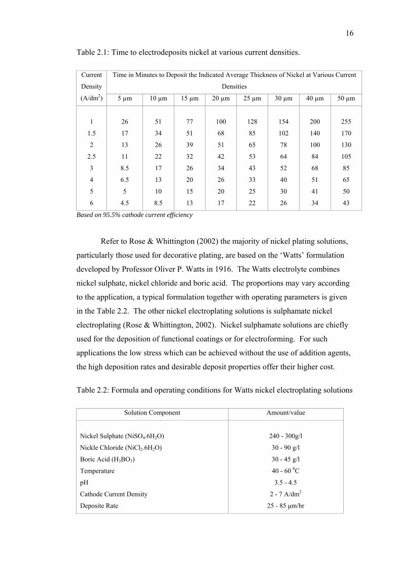
16
Table 2.1: Time to electrodeposits nickel at various current densities.
Time in Minutes to Deposit the Indicated Average Thickness of Nickel at Various Current
Densities
Current
Density
(A/dm2) 5 µm 10 µm 15 µm 20 µm 25 µm 30 µm 40 µm 50 µm
1 26 51 77 100 128 154 200 255
1.5 17 34 51 68 85 102 140 170
2 13 26 39 51 65 78 100 130
2.5 11 22 32 42 53 64 84 105
3 8.5 17 26 34 43 52 68 85
4 6.5 13 20 26 33 40 51 65
5 5 10 15 20 25 30 41 50
6 4.5 8.5 13 17 22 26 34 43
Based on 95.5% cathode current efficiency
Refer to Rose & Whittington (2002) the majority of nickel plating solutions,
particularly those used for decorative plating, are based on the ‘Watts’ formulation
developed by Professor Oliver P. Watts in 1916. The Watts electrolyte combines
nickel sulphate, nickel chloride and boric acid. The proportions may vary according
to the application, a typical formulation together with operating parameters is given
in the Table 2.2. The other nickel electroplating solutions is sulphamate nickel
electroplating (Rose & Whittington, 2002). Nickel sulphamate solutions are chiefly
used for the deposition of functional coatings or for electroforming. For such
applications the low stress which can be achieved without the use of addition agents,
the high deposition rates and desirable deposit properties offer their higher cost.
Table 2.2: Formula and operating conditions for Watts nickel electroplating solutions
Solution Component Amount/value
Nickel Sulphate (NiSO4.6H2O) 240 - 300g/l
Nickle Chloride (NiCl2.6H2O) 30 - 90 g/l
Boric Acid (H3BO3) 30 - 45 g/l
Temperature 40 - 60 0C
pH 3.5 - 4.5
Cathode Current Density 2 - 7 A/dm2
Deposite Rate 25 - 85 µm/hr

17
Some form of solution agitation and mixing is required in plating. Agitation
may be by forced air, mechanical stirring, controlled flow, or sonication. Mason
(2002) explains that, the effect of ultrasound has been extremely beneficial in
improving the hardness of nickel deposits. Using a variety of plating solutions it has
been shown that the presence of ultrasound improves the hardness of the coating with
the magnitude dependent on the particular bath composition employed.
The effects of ultrasonic agitation during the electrolysis must consider
cavitation phenomena-the collapse of cavitation bubbles in liquid-generated shock
wave pressure, the liquid jet, and water hammer pressure (Chiba et al., 2000). The
physical and chemical properties of electrodeposited films are affected by pressure
and flow leading to (i) increased current efficiency, rate of deposition, and limiting
current density; (ii) elimination of anodic polarization; (iii) minimized or eliminated
edge buildup; (iv) production of extremely uniform and well-bonded coatings; (v)
reduced porosity; and (vi) reduced particle size to produce a fine-grained deposit.
A type of nickel electrolytic deposition baths using ultrasound have been
developed by Chiba et al. (2000). The illustrations of the experimental will be
presented in Figure 2.7 which shows the position of the ultrasonic vibrator and
electrodes.
Figure 2.7: Position of electrodes and ultrasonic vibrator. (a) Cu plate; (b) Pt electrode; (c) bath; (d) cell; (e) ultrasonic source (Chiba et al., 2000)
N2
a b
c d
e
Cooling water Hot water
18
2.3 Ultrasonic treatment In some process, the ultrasonic treatment that applied called sonication (Chiba et al.,
2000). However, Suslick (2001) uses high intensity sound or ultrasound to alter
chemical reactions and called it sonochemistry. Mason (2002) also studies the
ultrasound to chemical processes and calls it sonochemistry as well.
Ultrasound is the part of the sonic spectrum which ranges from about 20 kHz
to 10 MHz and can be roughly subdivided in three main regions: low frequency, high
power ultrasound (20-100 kHz), high frequency, medium power ultrasound (100 kHz
- 1 MHz), and high frequency, low power ultrasound (2-10 MHz). The range from
20 kHz to around 1 MHz is used in ultrasonic treatment (Sweet, 1998).
The use of power ultrasonic to stimulate a process in liquid is currently the
trend in a wide range of materials science and technology. The application of
ultrasonic can used to produce and process materials that are often unobtainable by
conventional process routes. The effects of ultrasonic arise from acoustic cavitations
in a liquid (the formation, growth, and implosive collapse of bubbles). Ultrasonic
cavitations in liquid-solid systems produce related phenomena. Cavity collapse near
an extended solid surface becomes non-spherical, drives high speed jets of liquid into
the surface, and creates shockwave damage to the surface (Mason, 2002). Based on
this reason, ultrasonic is expected to stimulate the coating process of nickel on the
FeCrAl.
The cavitation phenomenon that causes erosion on a material surface is
discussed by Koivula (2000). This erosion process is as a mechanical degradation
which called cavitation erosion. It can be formed when cavity implosions are violent
enough, and they take place near enough to the solid material. Cavitation erosion can
be identified from a specific rough mark in surfaces of component flows paths. The
rough marks that resulted from cavitation on the FeCrAl substrate surface are believed
useful for electroplating process.
According to Koivula (2000), it is considered that there are two possible
mechanisms to cause cavitation erosion. When a cavity collapses within the body of
liquid, the collapse is symmetrical. The symmetrical collapse of a cavity emits a
shock wave to the surrounding liquid. When a cavity is in contact with or very close
to the solid boundary, the collapse is asymmetrical. In the asymmetrical collapse, the

19
cavity is perturbed from the side away from the solid boundary and finally the fluid
is penetrating through the cavity, and a micro-jet is formed (Figure 2.8).
Figure 2.8: The shock-wave mechanism and micro-jet mechanism of cavitation erosion. (Koivula, 2000)
Koivula (2000) argues when a cloud of cavities collapses, the cavities do not
act independently, but in concert (triggering each other’s collapse). The collapse of
the cavity cloud enhances the effects of the cavities adjacent to or in contact with the
solid boundary. Figure 2.9 shows the example of cavitation erosion resulted from
difference type of oil as the liquid that has been investigated by Koivula (2000). This
explanation is the main concept that implemented in this study.
Figure 2.9: Material loss due to cavitation erosion with different oil types (Koivula, 2000)

20
2.4 Development of oxide layer using a high temperature oxidation process
Oxidation is an environmental phenomenon in which metals and alloys (and
other materials) exposed to oxygen or oxygen-containing gases at elevated
temperatures convert some or all the metallic elements into their oxides (Young,
2009). The oxide can form as a protective scale if it remains adherent, and reduces
further oxidation, or may continually "spall off", exposing a fresh metal. The latter
results are in progressive metal loss. The technological implications of an oxidation
lie in the loss of load-bearing capability of the original metal or alloy component,
eventually resulting in component failure (Bose, 2007).
Two method oxidation processes were used; there are continuous oxidation
process by using a TGA and discontinuous oxidation process by using an automatic
furnace with cyclic oxidation approach (Birks et al., 2006). Thermogravimetry is the
measurement of mass change as a function of temperature or mass changes as a
function of time, at a constant temperature (Khanna, 2002). Oxidation studies are
usually carried out by exposing the specimen in a furnace at a fixed temperature and
measuring the weight change as a function of time Badini & Laurella (2001). This is
called isothermal oxidation test. Many such isothermal oxidation curves are
generated at various temperatures and then utilized to determine the activation
energy of the oxidation reaction. Sometimes oxidation test is carried out under
cyclic conditions of temperature. In this test, the sample is exposed to a cyclic
programmed, i.e. exposure for an affixed duration of time at a high temperature,
followed by cooling with a specific cooling Rte: holding it for a certain time period:
re-heating and holding it at a high temperature under similar conditions. Such tests
are carried out for a number of cycles ranging from 10-20 to 100-200. Weight
changes are measured after each cycle. Such test is known as a cyclic oxidation test
and then give information about the stability of the oxide scale under such as severe
oxidation condition not only of heating at a particular temperature but also under the
effect of thermal stresses, generated during thermal cycles (Khanna, 2002).
The preparation of specimens in oxidation test is usually referring to ASTM
G 54-84 (1996) standard. The results from oxidation test can be analyzed to obtain
parabolic rate constant (kp) follows the Wagner theory (Smallman & Bishop, 1999;
Badini & Laurella, 2001). For FeCrAl specimen, the kp value of oxidation test can
be used to predict the time to failure of FeCrAl substrate (Klower et al., 1998).

21
The Al2O3 layer is believed occurred on FeCrAl substrate after an oxidation
test (Klower et al., 1998; Badini & Laurella, 2001; Nicholls & Quadakkers, 2002;
Zhao et al., 2002; Twigg & Webster, 2006). It is caused by the Al element in the
FeCrAl substrate. At room temperature Al is always covered with 2-3 nm
amorphous alumina. At temperatures between 350 and 425 oC the amorphous film
grows with parabolic kinetics, and at a temperature above 425 the kinetics are
complex (Birks et al., 2006).
The NiO is believed can be produced from Ni by using an oxidation process.
Under normal temperature and pressure condition nickel only forms one oxide, NiO
(Birks et al., 2006). Meanwhile Wright & Andrew (1949) explain that the NiO has a
possibility to be formed through the oxidation of metal (pure nickel), it overcomes
the problem of powder material usage. Sato et al. (1998) invented that the nickel-
carbon composite film on the substrate in the foregoing manner (spattering) is then
heat-oxidized in an atmosphere of a gas comprising oxygen, such as air; to form the
desired nickel oxide film with a heating temperature of about 400 oC will suffice.
Young (2009) investigated that the significant developed NiO from Ni substrate
resulted at 900 oC and above. The early measurement by (Birks et al., 2006) shows
that the oxidation of nickel over temperature range 700 -1300 obtains a surprising
variation of the parabolic rate constant over four orders of magnitude.
Nickel as a catalyst is also in a form of nickel oxide (Heck et al., 2009). The
common nickel oxide catalyst is synthezed on a substrate directly from nickel oxide
powders. In this work, due to the nickel has coated on the FeCrAl substrate it is
possible to create nickel oxide by heating on elevated temperature. The elevated
temperature is also possible to develop an alumina layer on the FeCrAl substrate that
needed as washcoat. So that, as a part to understand the oxidation process this sub
chapter discusses about a high temperature oxidation process related to the
development of oxide layer.

CHAPTER 3
METHODOLOGY
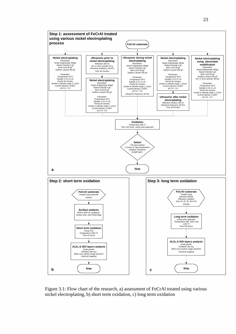
This chapter describes the steps of the research to obtain the best result for
preparation of NiO catalyst on FeCrAl substrate for catalytic converter application.
The approach was started with assessment of FeCrAl treated using various nickel
electroplating process based on the weight gain during oxidation, then short term
oxidation, and the last is long term oxidation. The steps are summarized as a
flowchart in Figure 3.1. The materials and experimental procedures that consist of
an electroplating, ultrasonic treatment, oxidation process, and characterization are
also described.
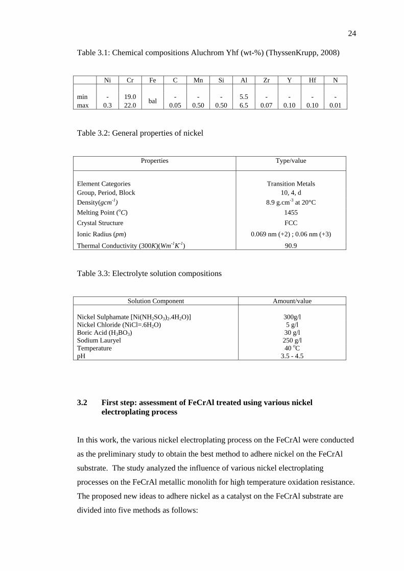
3.1 Materials The materials utilized in this research were: i) FeCrAl foils (strip) (Aluchrom Yhf)
supplied by ThyssenKrupp. VDM, Germany. The chemical component of Aluchrom
Yhf presented in Table. 3.1. ii) Al2O3 powder product of Merck, Germany. iii) SiC
powder supplied by Syarikat Saintifik Bersatu, Malaysia. iv) Nickel plate (pure
nickel) was supplied by Centre for Technology of Nuclear Industry Materials,
National Nuclear Energy Agency (BATAN) Indonesia. The general properties of
nickel is presented in Table. 3.2. v) Electrolyte solutions; nickel sulphamate type.
The composition of this solution is summarized in Table. 3.3.
23
Ultrasonic during nickel electroplating
Electrolyte:Nickel Sulphamate 300g/l
Nickel Chloride 5 g/lBoric Acid 30 g/l
Sodium Lauryel 250 g/l
Parameter:Temperature 40°CSample 2 cm x1 cmPeriod 30 minutes
Anode & cathode range + 2.5cmCurrent density 2 A/dm2
pH 3.5 - 4.5Ultrasonic frequency 35 kHz
Ultrasonic prior to nickel electroplating
Methanol 100 ml SiC or Al2O3 powder 20 g
Ultrasonic frequency 35 kHz Time 30 minutes
Nickel electroplatingElectrolyte:
Nickel Sulphamate 300g/lNickel Chloride 5 g/l
Boric Acid 30 g/lSodium Lauryel 250 g/l
Parameter:Temperature 40°CSample 2 cm x1 cmPeriod 30 minutes
Anode & cathode range + 2.5cmCurrent density 2 A/dm2
pH 3.5 - 4.5
Oxidation Temperature 900 oC
Time 100 hours using cyclic approach
Nickel electroplating using electrolyte
modificationElectrolyte:
Nickel Sulphamate 300g/lNickel Chloride 5 g/l
Boric Acid 30 g/lSodium Lauryel 250 g/l
SiC or Al2O3 powder 200 g/l
Parameter:Temperature 40°CSample 2 cm x1 cmPeriod 30 minutes
Anode & cathode range + 2.5cmCurrent density 2 A/dm2
pH 3.5 - 4.5
Nickel electroplatingElectrolyte:
Nickel Sulphamate 300g/lNickel Chloride 5 g/l
Boric Acid 30 g/lSodium Lauryel 250 g/l
Parameter:Temperature 40°CSample 2 cm x1 cmPeriod 30 minutes
Anode & cathode range + 2.5cmCurrent density 2 A/dm2
pH 3.5 - 4.5
Ultrasonic after nickel electroplating
Methanol solution 100 ml Ultrasonic frequency 35 kHz
Time 30 minutes
Nickel electroplatingElectrolyte:
Nickel Sulphamate 300g/lNickel Chloride 5 g/l
Boric Acid 30 g/lSodium Lauryel 250 g/l
Parameter:Temperature 40°C
Sample 2 cm x1 cmPeriod 30 minutes
Anode & cathode range + 2.5cmCurrent density 2 A/dm2
pH 3.5 - 4.5
Long term oxidation Using cyclic approach
Temperature 900, 1000, and 1100 oC
Time 100-hours
FeCrAl substrate
Select The best method
in terms of high temperature oxidation resistance
(weight gain).
Short term oxidation Using TGA
Temperature 1000 oCTime six hours
Al2O3 & NiO layers analysisOxide growth
Oxidation rate (kp)SEM cross section image and EDX
chemical mapping
Stop
Stop
Al2O3 & NiO layers analysisOxide growth
Oxidation rate (kp)SEM cross section image and EDX
chemical mapping
Stop
Surface analysis AFM & SEM on roughness,
surface area, and morphology
FeCrAl substrateTreated using
selected method. Ultrasonic variation
time 10, 20, 30, 40 & 50 minutes
FeCrAl substrateTreated using selected
method
Step 1: assessment of FeCrAl treated using various nickel electroplating process
Step 2: short term oxidation Step 3: long term oxidation
a
b c
Figure 3.1: Flow chart of the research, a) assessment of FeCrAl treated using various nickel electroplating, b) short term oxidation, c) long term oxidation
24
Table 3.1: Chemical compositions Aluchrom Yhf (wt-%) (ThyssenKrupp, 2008)
Ni Cr Fe C Mn Si Al Zr Y Hf N
min - 19.0 - - - 5.5 - - - - max 0.3 22.0 bal 0.05 0.50 0.50 6.5 0.07 0.10 0.10 0.01 Table 3.2: General properties of nickel
Properties Type/value
Element Categories Transition Metals Group, Period, Block 10, 4, d Density(gcm-1) 8.9 g.cm-3 at 20°C Melting Point (oC) 1455 Crystal Structure FCC
Ionic Radius (pm) 0.069 nm (+2) ; 0.06 nm (+3)
Thermal Conductivity (300K)(Wm-1K-1) 90.9 Table 3.3: Electrolyte solution compositions
Solution Component Amount/value
Nickel Sulphamate [Ni(NH2SO3)2.4H2O)] 300g/l Nickel Chloride (NiCl=.6H2O) 5 g/l Boric Acid (H3BO3) 30 g/l Sodium Lauryel 250 g/l Temperature 40 oC pH 3.5 - 4.5 3.2 First step: assessment of FeCrAl treated using various nickel
electroplating process In this work, the various nickel electroplating process on the FeCrAl were conducted
as the preliminary study to obtain the best method to adhere nickel on the FeCrAl
substrate. The study analyzed the influence of various nickel electroplating
processes on the FeCrAl metallic monolith for high temperature oxidation resistance.
The proposed new ideas to adhere nickel as a catalyst on the FeCrAl substrate are
divided into five methods as follows:

REFERENCES
Abdel Rahim, M.A., Abdel Hameed, R.M., & Khalil, M.W. (2004). Nickel as a
catalyst for the electro-oxidation of methanol in alkaline medium. Journal of
Power Sources, 134, pp.160–169.
Anderson, J. A. & García, M. F. (2005). Supported Metals in Catalysis. London:
Imperial College Press.
ASTM (1996). Standard Practice for Simple Static Oxidation Testing. America: G
54-84.
Ataee-Esfahani, H., Vaezi, M.R., Nikzad, L., Yazdani, B., & Sadrnezhaad, S.K.
(2009). Influence of Si-C nanoparticles and saccharin on the structure and
properties of electrodeposited Ni-Fe/SiC nanocomposite coatings. Alloys and
Compounds, 484, pp. 540-544.
Badini, C. & Laurella, F. (2001). Oxidation of FeCrAl alloy: influence of
temperature and atmosphere on scale growth rate and mechanism. Surface
and Coating Tecnology, 135, pp. 291-298.
Bartholomew, C. H. & Farrauto, R. J. (2006). Fundamentals of Industrial Catalytic
Processes 2nd ed. New Jersey. John Wiley & Son.
Birks, N., Meier, G.H. & Pettit, F.S. (2006). Introduction to The High-Temperature
Oxidation of Metals 2nd ed. New York. Cambridge University Press.
Bose, S. (2007). High Temperature Coatings. USA: Butterworth-Heinemann
(Elsevier).

76
Borchardt, G. & Strehl, G. (2002). On Deviations from Parabolic Growth Kinetics in
High Temperature Oxidation. in Bode, H. (Ed). Material Aspects in
Automotive Catalytic Converters. Germany: Wiley-VCH. pp. 31-48.
Brück, R. (2002). Development Status of Metal Substrate Catalysts. in Bode, H.
(Ed). Material Aspects in Automotive Catalytic Converters. Germany: Wiley-
VCH. pp. 19-30.
Casella, M.L., Nichio, N.N., Gonzalez, M.G., & Ferretti, O.A. (1998). Study of
different support and precursor compounds for supported nickel
oxyreforming catalysts. Materials Letters, 37, pp. 290–293.
Chiba. A., Gotou. T., Kobayashi, K., & Wu, W. (2000). Influence of sonication of
nickel plating in a nickel sulfamate bath. Metal Finishing 98 (9), pp. 66-69.
Corni, I., Ryan, M.P., & Boccaccini, A.R. (2008). Electrophoretic deposition: From
traditional ceramics to nanotechnology. Journal of the European Ceramic
Society, 28, pp. 1353–1367.
Cueff, R., Buscail, H., Caudron, E., Riffard, F., Issartel, C., & El Meski, S. (2004).
Effect of reactive element oxide coating on the high temperature oxidation
behaviour of FeCrAl alloys. Applied Surface Science, 229, pp. 233-241.
Di Bari, G.A. (2000). Electrodeposition of Nickel. in Schlesinger, M. & Paunovic,
M. (Eds). Modern Electroplating 4th ed. Canada: John Wiley & Sons, Inc.
Dou, D. (2005). NiO catalyst configurations, methods for making NOx adsorbers,
and methods for reducing emissions. US patent 6,930,073 B2.
Dueso, C., Abad, A., García-Labiano, F., Diego, L.F., Gayán, P., Adánez, J., &
Lyngfelt, A. (2010). Reactivity of a NiO/Al2O3 oxygen carrier prepared by
impregnation for chemical-looping combustion. Fuel, 89, 11, pp. 3399-3409.

77
Eleta, A., Navarro, P., Costa, L., & Montes, M. (2009). Deposition of zeolitic
coatings onto FeCrAlloy microchannels: Washcoating vs. in situ growing.
Microporous and Mesoporous Materials, 123, pp. 113–122.
Ersson, A.G. & Järås, S.G. (2006). Catalytic Fuel Combustion in Honeycomb
Monolith Reators. in Cybulski, A. & Moulijn, J.A. (Eds). Structured
Catalysts and Reactors 2nd ed. USA: Taylor & Francis Group. pp 233-237.
Fonseca, A. & Assaf, E.M. (2005). Production of the hydrogen by methane steam
reforming over nickel catalysts prepared from hydrotalcite precursors.
Journal of Power Sources, 142, pp.154–159.
Fukuda, K., Takao, K., Hoshi, T., & Furukumi, O. (2002). Improved High
Temperature Oxidation Resistance of REM Added Fe-20%Cr-5%Al Alloy by
Pre-Annealing Treatment. in Bode, H. (Ed). Material Aspects in Automotive
Catalytic Converters. Germany: Wiley-VCH. pp. 59-82.
Gulati, S. T. (2006). Ceramic Catalyst Support for Gasoline Fuel. in Cybulski, A. &
Moulijn, J. A. (Eds). Structured Catalysts and Reactors 2nd ed. USA: Taylor
& Francis Group.
Hasssan, M.F., Sebayang, D., & Untoro, P. (2009). Apparatus for Producing A Spiral
Shape of Corrugated Sheet Metal for Substrate of Catalytic Converter.
Proceeding of ICAME 09. Malaysia.
Hasyim, M. (2009).The Effect of Current Density on Electroplating of FeCrAl with
Nickel. UTHM. Malaysia. Undergraduate Thesis.
Hayes, R.E. & Kolaczkowski, S.T. (1997). Introduction to Catalytic Combustion.
Netherlands: Gordon and Breach Science Publishers.
Heck, R.M. & Farrauto, R.J. (2001). Automobile exhaust catalysts. Applied Catalysis
A: General, 221, pp. 443-457

78
Heck, R.M., Farrauto, R.J., & Gulati, S.T. (2002). Catalytic Air Pollution Control
Comercial Technology 2nd ed. USA: John Wiley & Sons, Inc.
Heck. R. M., Farrauto, R. J., & Gulati, S. T. (2009). Catalytic air pollution control
commercial technology 3rd ed. USA: John Wiley & Sons, Inc.
Henke, L., Nagy, N., & Krull, U.J. (2002). An AFM determination of the effects on
surface roughness caused by cleaning of fused silica and glass substrates in
the process. Biosensors and Bioelectronics, 17, pp. 547-555.
Hirota, K. (2009). Policy for better Air Quality in Asia: Proposal for a Policy
Evaluation Method for four ASEAN Countries. Studies in Regional Science,
38, 4, pp.1093-1104.
Huang, Y. & Bar-Ilan, A. (2003). Method for washcoating a catalytic material onto
a monolithic structure. U. S. Patent 6759358.
Jang. B., Helleson M., Shi .C., Rondinone, A., Schwartz, V., Lian, C., & Overbury,
S. (2008). Characterization of Al2O3 supported nickel catalysts derived from
RF non-thermal plasma technology. Topics in Catalysis, 49, pp. 145–152.
Jia, L., Shen, M., & Wang, J. (2007). Preparation and characterization of dip-coated
γ-alumina based ceramic materials on FeCrAl foils. Surface & Coatings
Technology, 201, pp. 7159–7165.
Khanna, A.S. (2002). Introduction to High Temperature Oxidation and Corossion.
ASM International.
Kis, E., Marinkovic-Neducin, R., Lomic, G., Boskovic, G., Obadovic, D. Z., Kiurski
J., & Putanov, P.(1998). Structural and textural properties of the NiO-Al2O3
catalyst. Polvhedron, 17(1), pp. 27-34.
Klöwer, J., Kolb-Telieps, A., Bode, H., Brede, M., Lange, J., Brück, R., Wieres, L.
(1998). Development of high-temperature corrosion resistant FeCrAl alloys
for automotive catalytic converters. Germany: Krupp VDM GmbH.
79
Koivula, T. (2000). On Cavitation in Fluid Power. Proceeding of 1st FPNI-PhD
Symposium Hamburg: pp. 371-382.
Koltsakis, G.C. & Stamatelos, A.M. (1997). Catalytic automotive exhaust after
treatment. Progress in Energy and Combustion Science, 23, pp.1-39.
Lylykangas,R. & Tuomola, H. (2002). A New Type of Metallic Substrate. in Bode,
H. (Ed). Material Aspects in Automotive Catalytic Converters. Germany:
Wiley-VCH. pp. 152-170.
Mason,T.J. (2002). The Uses of Power Ultrasound in Chemistry and Processing-
Applied Sonochemistry. Germany: Wiley-VCH.
Mies, M.J.M., Rebrov, E.V., Jansen, J.C., Croon, M.H.J.M., & Schouten, J.C.
(2007). Hydrothermal synthesis of a continuous zeolite Beta layer by
optimization of time, temperature and heating rate of the precursor mixture.
Microporous and Mesoporous Materials, 106, pp. 95–106.
Nicholls, J. R. & Quadakkers, W. J. (2002). Materials Issues Relevant to the
Development of Future Metal Foil Automotive Cataltic Converters. in Bode,
H. (Ed). Material Aspects in Automotive Catalytic Converters. Germany:
Wiley-VCH. pp. 31-48.
Ochoa-Fernandeza, E., Lacalle-Vilaa, C., Christensena, K. O., Walmsleyb, J. C.,
Rnninga, M., Holmena, A., & Chena, D. ( 2007). Ni catalysts for sorption
enhanced steam methane reforming. Topics in Catalysis, 45, pp. 1-4.
Quintana-Melgoza, JM., Gómez-Cortés, A., & Avalos-Borja, M. (2002). Reduction
of NO by CO over NIWO4, NIO, and WO3 catalysts. Reaction Kinetic
Catalytic Letter, 76, pp. 131-140.
Rose, I. & Whittington, C. (2002). Nickel Plating Handbook. Finland: OMG Group.
Sato, Y., Tamura, S., Mochizuki, S., & Mihara, T. (1998). Process for Producing
Nickel Oxide Film. U.S. Patent 5798134.

80
Searles, R. A. (2002). Contribution of Automotive Catalytic Converters. in Bode, H.
(Ed.). Material Aspects in Automotive Catalytic Converters. Germany:
Wiley-VCH. pp. 4-16.
Sebayang, D., Untoro, P., Putrasari, Y., Hashim, M., Soon, Y.H., & Gooma, M.
(2009). Influence of difference deposition technique of nickel on the FeCrAl
metallic monolith. Malaysian Metallurgical Conference. Perlis: Universiti
Malaysia Perlis.
Sebayang, D., Amirnordin, S.H., Untoro, P., & Abd Rahman, H. (2006). Current
Status on The Development of catalytic Converter Project. 1st Malaysian
Technical University Colleges Annual Conference on Engineering and
Technology (MUCET). Malaysia.
Sebayang, D., Putrasari, Y., Hasan, S., & Untoro, P. (2010). NiO development on
FeCrAl substrate for catalytic converter using ultrasonic and nickel
electroplating methods. Advanced Material Research Journal, 129-131, pp.
1262-1266.
Sebayang, D., Untoro, P., Aminordin, S.H., & Abd Rahman, H. (2007).
Development of an Innovative Three Way Catalytic Converter: Effort and
Challenge. World Engineering Congress, Institute of Engineers Malaysia
(IEM). Malaysia.
Sebayang, D., Untoro, P., & Putrasari, Y. (2010). Effect of pretreatment using
ultrasonic technique with SiC or Al2O3 on high temperature oxidation
behavior of the FeCrAl. Proceeding of the 14th International Conference on
Applied Mechanics and Mechanical Engineering AMME-14, Egypt: Military
Technical College Cairo.
Sebayang, D., Untoro, P., Syahril, Hassan, S., Othman, M.A. (2009). Regional
Cooperation on Research of Advance Material and Failure Analysis - 6 Years
of Research Cooperation Between Universiti Tun Hussein Onn Malaysia

81
(UTHM) and Badan Tenaga Nuklir Indonesia (BATAN). 7th ASEAN
Microscopy Conferences 2009. Indonesia.
Shi, P., & Liu, C.J. (2009). Characterization of silica supported nickel catalyst for
methanation with improved activity by room temperature plasma treatment.
Catalyst Letter ,133, pp.112–118.
Sivaiah, M.V., Petit, S., Beaufort, M.F., Eyidi, D., Barrault, J., Batiot-Dupeyrat ,C.,
& Valange, S. (2010). Nickel based catalysts derived from hydrothermally
synthesized 1:1 and 2:1 phyllosilicate as precursors for carbon dioxide
reforming of methane. Microporous and Mesoporous Materials, 0(0).
Retrieved October 20, 2010, from doi: 10.1016/j.micromeso.2010.09.015.
Smallman, R.E., & Bishop, R.J. (1999). Modern Physical Metallurgy and Materials
Engineering Science, Process, Applications 6th ed. Butterworth-Heinemann,
Elsevier.
Sudrajad, A. (2005). Pencemaran Udara Suatu Pendahuluan. Jurnal Inovasi LIPI , 5,
/XVII. pp. 51-55. Retrieved August 20, 2009, from:
http://www.scribd.com/doc/9685565/inovasi-vol5-xvii-november-2005
Sun, H., Quan, X., Chen,S., Zhao, H., & Zhao, Y. (2007). Preparation of well-
adhered g-Al2O3 washcoat on metallic wire mesh monoliths by
electrophoretic deposition. Applied Surface Scienc, 253, pp. 3303–3310.
Suslick, K.S. (2001). Sonoluminescense and Sonochemistry. in Mayers, R.A. (Ed.).
Encyclopedia of Physical Science and Technology 3rd ed. San Diego:
Academic Press.
Sweet, J.D. (1998). Materials And Environmental Applications For Sonochemistry.
Graduate Faculty of Texas Tech University. PhD tesis.
Twigg, M. V. & Webster, D. E. (2006). Metal and Coated Metal Catalysts. in
Cybulski, A. & Moulijn, J. A. (Eds). Structured Catalysts and Reactors 2nd
ed. USA: Taylor & Francis Group. pp. 109-146.
82
Taniguchi, S., Andoh, A., & Shibata, T. (2002). Improvement in The Oxidation
Resistance of Al-deposited Fe-Cr-Al Foil by Pre-oxidation. in Bode, H. (Ed).
Material Aspects in Automotive Catalytic Converters. Germany: Wiley-VCH.
pp. 83-105.
Thyssen Krupp VDM (2008). Aluchrom Yhf Material Data Sheet No. 4049. Germany
March 2008: Product Data sheet.
Wei, Q., Chen, Z.X., Nie, Z.R., Hao, Y.L., Zou, J.X., & Wang, Z.H. (2005).
Mesoporous activated alumina layers deposited on FeCrAl metallic substrates
by an in situ hydrothermal method. Journal of Alloys and Compounds, 396,
pp. 283–287.
Wright, R. W. & Andrews, J. P. (1949). Temperature variation of the electrical
properties nickel oxide. Proceeding of the Physics Society A 62 446.
Retrieved December 23, 2009, from: http://iopscience.iop.org/0370-
1298/62/7/306
Wu, X., Weng, D., Zhao, S., & Chen, W. (2007). Influence of an aluminized
intermediate layer on the adhesion of a g-Al2O3 washcoat on FeCrAl. Surface
& Coatings Technology, 190, pp. 434– 439.
Xiancai, L., Quanhong, H., Yifeng, Y., Juanrong, C., & Zhihua, L., (2008). Effects of
sol-gel method and lanthanum addition on catalytic performances of nickel-
based catalysts for methane reforming with carbon dioxide. Journal of Rare
Earths, 26, pp. 864-868.
Xiang, L., Gong, Y.L., Li, J.C., & Wang, Z.W. (2004). Influence of hydrothermal
modification on the properties of Ni/Al2O3 catalyst. Applied Surface Science,
239, pp. 94–100.
Xu, X. & Moulijn, J.A. (2006). Transformation of Structured Carrier into a
Structured Catalyst. in Cybulski, A. & Moulijn, J.A. (Eds.). Structured
Catalysts and Reactors 2nd ed. USA: Taylor & Francis Group. pp 751-777.

83
Yanqing, Z., Jieming, X., Cuiqing, L., Xin, X., & Guohua, L. (2010). Influence of
preparation method on performance of a metal supported perovskite catalyst
for combustion of methane. Journal of Rare Earths, 28 (1), pp. 54-58.
Young, D. J. (2009). High Temperature Oxidation and Corrosion of Metals.
Elsevier. pp. 97-99.
Zamaro, J.M., Ulla, M.A., & Miro, E.E. (2008). ZSM5 growth on a FeCrAl steel
support. Coating characteristics upon the catalytic behavior in the NOx SCR.
Microporous and Mesoporous Materials, 115, pp. 113–122.
Zeifert, B.H., Salmones, J., Hernandez, J.A., Reynoso, R., Nava, N., Cabanas-
Moreno, J.G., & Aguilar-Rıos, G. (2000). Preparation of iron–nickel catalysts
by mechanical alloying". Materials Letters, 43, pp. 244–248.
Zhao, S., Zhang, J., Weng, D., & Wu, X. (2003). A method to form well-adhered γ-
Al2O3 layers on FeCrAl metallic supports. Surface and Coating Technology,
167, pp. 97-105.