preparatory survey report on the flood …open_jicareport.jica.go.jp/pdf/12122578_01.pdf · river....
TRANSCRIPT

Royal Irrigation Department Ministry of Agriculture and Cooperatives Kingdom of Thailand
PREPARATORY SURVEY REPORT ON
THE FLOOD PREVENTION PROJECT OF EAST SIDE OF THE PASAK RIVER IN AYUTTHAYA
IN THE KINGDOM OF THAILAND
October 2012
JAPAN INTERNATIONAL COOPERATION AGENCY
CTI ENGINEERING INTERNATIONAL CO., LTD. ORIENTAL CONSULTANTS CO., LTD.
NIPPON KOEI CO., LTD. CTI ENGINEERING CO., LTD. GE
JR
12-131


Royal Irrigation Department Ministry of Agriculture and Cooperatives Kingdom of Thailand
PREPARATORY SURVEY REPORT ON
THE FLOOD PREVENTION PROJECT OF EAST SIDE OF THE PASAK RIVER IN AYUTTHAYA
IN THE KINGDOM OF THAILAND
October 2012
JAPAN INTERNATIONAL COOPERATION AGENCY
CTI ENGINEERING INTERNATIONAL CO., LTD. ORIENTAL CONSULTANTS CO., LTD.
NIPPON KOEI CO., LTD. CTI ENGINEERING CO., LTD.


PREFACE
Japan International Cooperation Agency (JICA) decided to conduct the preparatory survey and
entrust the survey to the Joint Venture consist of CTI Engineering International Co., Ltd., CTI
Engineering Co., Ltd., Oriental Consultants Co., Ltd. and Nippon Koei Co., Ltd..
The survey team held a series of discussions with the officials concerned of the Government of the
Kingdom of Thailand, and conducted field investigations. As a result of further studies in Japan,
the present report was finalized.
I hope that this report will contribute to the promotion of the project and to the enhancement of
friendly relations between our two countries.
Finally, I wish to express my sincere appreciation to the officials concerned of the Kingdom of
Thailand for their close cooperation extended to the survey team.
October, 2012
Masami FUWA Director General, Global Environment Department Japan International Cooperation Agency


s-i
SUMMARY
(1) Overview of the Kingdom of Thailand The Kingdom of Thailand (hereinafter referred to as “Thailand”) is located at central of Indochina and borders on Cambodia at east, Laos at north, Myanmar at west and Malaysia at south. The total land of Thailand is about 514,000 km2. The population is about 65,900,000 in 2010. Tropical monsoon contribute largely to the rainfall in Thailand from middle of May to October. Ayutthaya Province where the Project is located is plain area facing the Chao Phraya River and about 70km far from Bangkok, the capital of Thailand. In Phra Nakhon Si Ayutthaya Province, there are about 780,000 populations in 2009 and the historic city of Ayutthaya Dynasty which was registered to the UNESCO World Heritage. Moreover, there are many industrial estates in/surround Ayutthaya Province and many Japanese factories operate. The annual mean low and high temperature are 21.9 degrees Celsius and 32.4 degrees Celsius, respectively. The annual average rainfall is 1,424 mm during last 30 years and 88% of annual rainfall concentrates during May to October. Thailand has undergone a rapid economic development since the late1980s as a result of the promotion of export promotion policy through the industrialization of the underlying direct foreign investment in Japan and others. After the Asian economic crisis occurred late 1990s, the Government of Thailand (GOT) has strived to economic reconstruction with the assistance of the international community. Therefore, the continuously sluggish economic performance in Thailand was recovered. As a result of the export-led as ever and the expansion of domestic demand policy, the economic growth in Thailand was relatively high until year 2007. The economy in Thailand was sluggish to slow down of exports that affected from the recession of external demand by the global economic crisis stemming from the collapse of Lehman Brothers in 2008. The Gross Domestic Production (GDP) growth rate in 2008 and 2009 was 2.5% and -2.3%, respectively. Thereafter, the economy in Thailand was recovered and GDP growth rate was recorded at 7.8% due to the economic recovery of overseas export markets. However, the GDP growth rate in 2011 fell 0.1% because of serious flood damage.
(2) Background, History, Outline of the Requested Project More than 61 provinces in the Kingdom of Thailand have been extensively flooded in 2011 due to rainfalls intermittently continued since July 2011 which was caused by more than 100-year probable rainfall estimated. The extent of flood damages in the Chao Phraya River Basin with area of 160,000 km2 were about 1,200,000 households (3.2 million people) inundated, 446 dead, and about 17,000 km2 farmland inundated at 25 provinces in Basin, according to the announcement of GOT on 5 November 2011. The flood damage has

s-ii
extensively expanded to Bangkok, Phra Nakhon Si Ayutthaya Province in where many industrial estates are located, including urban areas in Nonthaburi Province and Pathum Thani Province located at northern area of Bangkok. There are two canals connecting to the Pasak River; Han Tra Canal and Kra Mang Canal. These two canals join and become Khao Mao Canal. These canals function as drainage channel to lead drainage water in the low land area at the left bank of the Pasak River to the Pasak River. During the 2011 flood, the floodwater of the Pasak River has entered into the Han Tra Canal and Kra Mang Canal. Hence, the gates of the existing Khao Mao Floodgate (regulator) were closed to prevent the floodwater of the Pasak River. However, the gate height was not enough against the flood water level of the Pasak River. Then, the floodgate became structurally dangerous situation. Then, the gates were opened. The flood flowed into the Khao Mao Canal and overtopped on the bank. Finally, the southern area of the Khao Mao Canal in where major industrial estates are located including many industrial estates was inundated. It was understood that the prevention of floodwater of the Pasak River into the canals on left bank contribute to the safety of residents in this area and the flood mitigation in the industrial estates downstream. In view of this, the Government of Japan has decided to carry out the preparatory survey for protection of the Flood Prevention Project of East Side of the Pasak River in Ayutthaya.
(3) Outline of Study Results and Contents of the Project JICA dispatched the preparatory survey team to Thailand from 25 December 2011 to 31 August 2012. In Thailand the survey team held a series of discussions with the officials concerned of the GOT on the request of GOT, and conducted the field investigations (topography, geology, and underground water) and surveys for social conditions, buried facilities at sites, and procurement conditions of construction equipment/materials, etc. Based on the results of survey, analysis and design conducted in Thailand and Japan, a mission for the briefing on the detail design was dispatched by JICA and held discussions regarding the direction of the detail design and the burden of the GOT, etc. Both governments confirmed the survey results. The outline of the final plan is as described below.
• 2-phased Implementation After the 2011 flood, the RID has planned the flood protection works for the left bank area (east area) of Pasak River by construction of the Han Tra Floodgate and Kra Mang Floodgate, and construction of flood wall along the left bank of Pasak River between two proposed floodgates and flood wall along the Han Tra Canal up to the existing national road No. 3053. However, some stakeholders expressed disagreement on the RID’s plan to construct the proposed Kra Mang Floodgate and flood wall in the public consultation meeting held

s-iii
because of social problems such as necessity of relocation of residents at the proposed locations of floodgate and flood wall. In order to mitigate the flood damage such as the 2011 flood, construction of floodgates and flood walls are indispensable. In view of this situation, the phased implementation was proposed by JICA survey team and accepted.
1st Stage: Han Tra Floodgate is constructed at just downstream of the bridge of road root 3053 and Kra Mang Floodgate is constructed at just upstream of the railway bridge. These floodgates and existing bridges are connected with flood walls. As a first stage implementation of flood wall along the Han Tra Canal, the river bank protection works with a top elevation of EL.+4.5 m MSL are constructed. 1st stage implementation covers the 90% of the project area. Direct construction cost and cost for consultant services will be covered by Japan Grant Aid. On the other hand, the GOT covers costs for land acquisition and compensation, relocation of existing utilities, extension of electric power line to the site, etc.
2nd Stage: The flood damage of the remaining 10% area between the Pasak River and road no. 3053 are mitigated by the construction of flood walls, including flood wall along the left bank of the Pasak River between the Han Tra Floodgate and Kra Mang Floodgate and flood wall along the Pasak River on the north of Han Tra Canal. Moreover, flood wall with EL.+6.5 m along the Han Tra Canal is constructed on the river bank protection to be constructed under the 1st stage implementation. All necessary cost is covered by the GOT.
• Floodgate Construction Plan Design high water level (EL.+6.00 m MSL) of proposed two floodgates is determined based on the recorded highest water level of the Pasak River at the Ayutthaya Water Level Gauging Station. Floodwater such as the 2011 flood can be prevented by the proposed floodgates. Regarding the material of hydraulic gate leaves, guides and wire ropes, stainless steel which does not require painting work for corrosion-resistance is utilized to minimize the maintenance cost. The river bank protection with a top elevation of EL.+4.5 m along the low Han Tra Canal downstream from the proposed Han Tra Floodgate to the Pasak River is to be constructed as a first stage implementation, taking the difficulty of necessary land acquisition within the limited time and the social environmental consideration into account.
• Drainage Pump Vehicles The reverse flow from the Pasak River will be prevented by closing gates of proposed Han Tra and Kra Mang Floodgates and existing Khao Mao Floodgate during the flood. In this case, it is required to drain mechanically rainwater in the area enclosed by the floodgates. Hence, the utilization of drainage pump vehicle with a capacity of 30 m3/min is proposed

s-iv
taking the necessary mobility and drainage capacity into account. A total of 10 pump vehicles are to be provided to the RID Ayutthaya Irrigation Project Office. During the 2001 flood, the floodwater in Ayutthaya area and industrial estates was drained by using the 10 drainage pump vehicles which were urgently conveyed from Japan as an international relief assistance. These drainage pump vehicles have showed the excellent result for drainage. In view of this situation, it is proposed to use widely the drainage pump vehicles even in the jurisdiction of RID Regional Irrigation Office 10.
<Facility Overview>
Items Dimensions
Gate Type Curtain walled type 4 sided watertight stainless steel fixed wheel gate
Dimension of Gate 6.0 m clear span x 7.1 m effective height Number of Gates 3 nos.
Hoist Wire rope winched 1 motor 2 drum type hoist (3 phase x 380 V x 50 Hz)
Top Elevation of Gate EL. +4.6 m MSL Bottom Elevation of Gate EL. -2.5 m MSL Top Elevation of Floodgate EL. +7.5 m MSL
1. Han Tra floodgate
Hoist Deck 4.5 m width x 26 m long, EL.+15.0 m MSL
Stoplog
6.0 m clear span x 1.0 m effective height x 5 pieces x 2 sides (downstream and upstream). Telpher rail. Manual chain hoist. Lifting beam.
Main Civil Structure Reinforced concrete base, pier, deck.
Maintenance Bridge Reinforced concrete slab type. 3 m wide at upstream side. 2 m wide at downstream side.
Backup Power Supply System Diesel engine generator: 1 phase 220 V/3 phase 380V x 50Hz x 20kVA
Incidental Equipment 2-Water level gauge. Lighting facility. Lightning rod.
Hoist Room Shaped steel frame with roof without wall Foundation Type PC Pile (600 mm diameter) Cut-off Wall Steel sheet pile Wing Wall Reinforced concrete retaining wall
Apron Reinforced concrete, 6 m long upstream/downstream, respectively.
Riverbed Protection Gabion mattress; 14 m long upstream/downstream sides respectively
Floodwall Double PC corrugated sheet piling with soil filling
Structural Type Slope protection consisting of PC corrugated sheet piles, Concrete crib work and Stone facing
Length 212 m (Left) + 272 m (Right) = 484 m (Total)
Elevation of Pile Coping EL. +2.5 m MSL
Top Elevation of Embankment
EL. +4.5 m MSL
Slope 1:2.0
2. River Bank Protection in Lower Han Tra Canal
Miscellaneous Works 2 drainage outlets with flapgates. 484 m long ditches along slope protection. 10 stairs for access.

s-v
Items Dimensions
Gate Type Curtain walled type 4 sided watertight stainless steel fixed wheel gate
Dimension of Gate 6.0 m clear span x 5.1 m effective height Number of Gates 3 nos.
Hoist Wire rope winched 1 motor 2 drum type hoist (3 phase x 380 V x 50 Hz)
Top Elevation of Gate EL. +4.6 m MSL Bottom Elevation of Gate EL. -0.5 m MSL Top Elevation of Floodgate EL. +7.5 m MSL Hoist Deck 4.5 m width x 26 m long, EL.+13.0 m MSL
Stoplog
6.0 m clear span x 1.0 m effective height x 3 pieces x 2 sides (downstream and upstream). Telpher rail. Manual chain hoist. Lifting beam.
Hydraulic Gate Works for Drainage
4 sided watertight stainless steel fixed wheel gate, 2.0 m width x 1.5 m height. Manual racked gate hoist.
Backup Power Supply System Diesel engine generator: 1 phase 220 V/3 phase 380 V x 50 Hz x 20 kVA
Incidental Equipment 2-Water level gauge. Lighting facility. Lightning rod.
Main Civil Structure Reinforced concrete base, pier, deck.
Maintenance Bridge Reinforced concrete slab type. 3 m wide at upstream side. 2 m wide at downstream side.
Hoist Room Shaped steel frame with roof without wall Foundation Type PC Pile (600 mm diameter) Cut-off Wall Steel sheet pile Wing Wall Reinforced concrete retaining wall
Apron Reinforced concrete, 6 m long upstream/downstream, respectively.
Riverbed Protection Gabion mattress; 14 m long upstream/downstream sides respectively
3. Kra Mang Floodgate
Floodwall Double PC corrugated sheet piling with soil filling and U-type retaining wall
Drainage capacity 0.5 m3/sec/unit (30 m3/min/unit) Total head 10 m Pump type Submersible motor driving pump Pump power source 3 phase x 440 V x 60 Hz Generator 125 kVA diesel generator Truck capacity GVW 10,000 kg or less
4. Drainage Pump Vehicle
Number of vehicles 10
(4) Implementation Schedule and Project Cost Estimate Under the Grant Aid of Japan, the Project is scheduled to complete in 21 months consisting of 4-month tendering and 17-month construction. Cost to be born by Thailand is estimated at 19.0 million Baht.
(5) Project Evaluation
The Project will provide the following benefits as shown in table below to the local resident at east area of the Pasak River and industrial estates in Ayutthaya:

s-vi
<Project Effects and Degree of Improvements>
Present Situation and Problems
Measures Taken by the Project
Direct Effects/Benefits Indirect Effects/Benefits
In case water rise up to EL.+6.0 m which is the same as 2011 flood, not only local residences but also industrial estates suffer serious flood damage.
(1) Construction of Han Tra Floodgate, Kra Mang Floodgate and Riverbank Protection at downstream of Han Tra Canal
(2) Procurement of
Drainage Pump Vehicles
(1) Direct Effects The Project prevents floodwater of Pasak River, which is the same water level as 2011 flood, into Han Tra and Kra Mang Canals. (2) Benefit The Project mitigates flood damage due to the reverse flow of Pasak River into both Canals.
(1) Mentally helpful for local residents and the concerned of industrial estates during flood event.
(2) Increasing the stable
business operations and enhancing the reliability of the GOT.
Implementation of the Project will contribute to the protection of the east side of the Pasak River from the flood and mitigation of flood damage of the industrial estates in the downstream area. Through executing the Japan grant aid project, further enhancement of the friendly relations between two countries is expected.

i
Table of Contents
Preface Summary Table of Contents Location Map/ Perspective List of Figures and Tables Abbreviations
Page
Chapter 1. Background of the Project ........................................................................................ 1-1
1-1 Current Status and Issues of Sectors Involved..................................................................... 1-1
1-1-1 Current Status and Issues ............................................................................................. 1-1
1-1-2 Development Plan ........................................................................................................ 1-4
1-1-3 Socio-Economy ............................................................................................................ 1-5
1-2 Background, History and Overview of the Grant Aid.......................................................... 1-6
Chapter 2. Contents of the Project ............................................................................................. 2-1
2-1 Basic Concept of the Project................................................................................................ 2-1
2-1-1 Overall Goal and Purpose of The Project ..................................................................... 2-1
2-1-2 Contents of The Project ................................................................................................ 2-1
2-2 Outline Design..................................................................................................................... 2-5
2-2-1 Design Policy ............................................................................................................... 2-5
2-2-2 Basic Plan..................................................................................................................... 2-9
2-2-3 Detail Design Drawing ............................................................................................... 2-26
2-2-4 Implementation Plan................................................................................................... 2-26
2-3 Obligations of Recipient Country ...................................................................................... 2-40
2-3-1 Obligation of the Government of Thailand................................................................. 2-40
2-3-2 Appropriateness and Possibility of Execution for Allotted Items of the Project Implementation by Thailand ...................................................................................... 2-41
2-4 Project Operation Plan....................................................................................................... 2-42
2-5 Project Cost Estimation ..................................................................................................... 2-42
2-5-1 Initial Cost Estimation................................................................................................ 2-42
2-5-2 Operation and Maintenance Cost................................................................................ 2-43

ii
Chapter 3. Project Evaluation .................................................................................................... 3-1
3-1 Precondition......................................................................................................................... 3-1
3-2 Necessity Inputs by Recipient Country................................................................................ 3-1
3-3 Important Assumptions........................................................................................................ 3-1
3-4 Project Evaluation ............................................................................................................... 3-2
3-4-1 Relevance ..................................................................................................................... 3-2
3-4-2 Effectiveness ................................................................................................................ 3-2
[Appendices]
1. Member List of the Survey Team ............................................................................................A1-1 2. Survey Schedule ......................................................................................................................A2-1 3. List of Parties Concerned in Thailand......................................................................................A3-1 4. Minutes of Discussions ............................................................................................................A4-1 5. Soft Component Plan ...............................................................................................................A5-1 6. Abbreviated Resettlement Action Plan ....................................................................................A6-1 7. Technical Note.........................................................................................................................A7-1 8. Drawings..................................................................................................................................A8-1

iii
Location Map
Existing Supachai Pumping Station
Existing Suan Plu Gate
N
iv
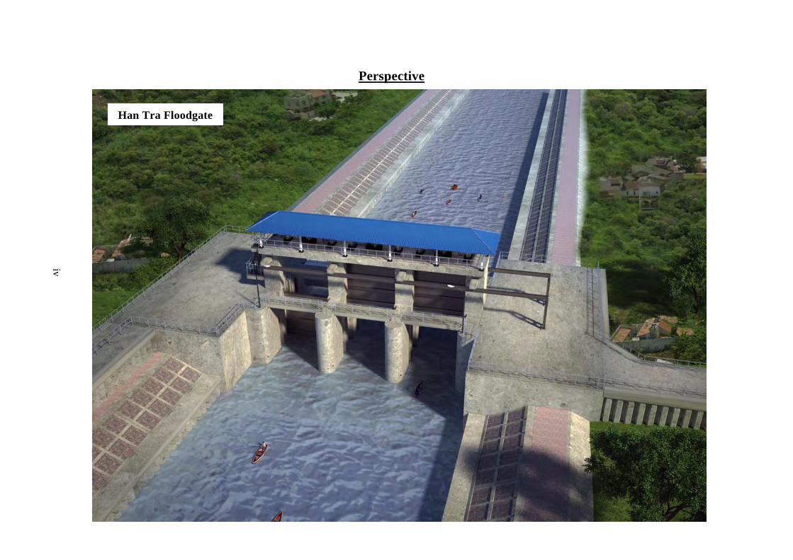
Perspective
Han Tra Floodgate

v
Kra Mang Floodgate

vi
List of Figures and Tables
Tables
Page
Table 1-1.1 Direct Damages and Losses by 2011flood ....................................................... 1-2
Table1-1.2. Affected Agricultural Population and Farmland Area by 2011 year Flood...... 1-2
Table 1-2.1 Contents of Request ......................................................................................... 1-6
Table 2-2-2.1 Major Specifications of Drainage Pump Vehicle to be Procured................ 2-25
Table 2-2-4.1 Obligations of the GOJ and the GOT ......................................................... 2-29
Table 2-2-4.2 Construction / Procurement Management System of the Consultant .......... 2-31
Table 2-2-4.3 Quality Control Plan................................................................................... 2-32
Table 2-2-4.4 List of Spare Parts ...................................................................................... 2-35
Table 2-2-4.5 Source Countries of Equipment and Materials ........................................... 2-36
Table 2-5-1.1 Cost to be Born by Government of Thailand .............................................. 2-42
Table 2-5-2.1 Annual Operation and Maintenance Cost ................................................... 2-44
Table 3-4-2.1 Quantitative Effectiveness ............................................................................ 3-2
Figures
Page
Figure 2-2-1.1 Design Water Level..................................................................................... 2-6
Figure 2-2-1.2 Seismic Coefficient ..................................................................................... 2-6
Figure 2-2-2.1 Flood Prevention Plan to Left Bank of Pasak River prepared by RID ........ 2-9
Figure 2-2-2.2 Concept of Phased Implementation ........................................................... 2-10
Figure 2-2-2.3 Location of Han Tra Floodgate (North Side) ............................................ 2-11
Figure 2-2-2.4 Front View of Han Tra Floodgate ............................................................. 2-11
Figure 2-2-2.5 Profile of Han Tra Floodgate..................................................................... 2-12
Figure 2-2-2.6 Profile of Han Tra Channel ....................................................................... 2-12
Figure 2-2-2.7 Sample of Floodgate with Curtain Wall .................................................... 2-13
Figure 2-2-2.8 Plan of Downstream River Bank Protection in Han Tra Canal.................. 2-16
Figure 2-2-2.9 Typical Section of Downstream River Bank Protection in Han Tra Canal 2-16
Figure 2-2-2.10 Location of Kra Mang Floodgate (South Side) ....................................... 2-18

vii
Figure 2-2-2.11 Front View of Kra Mang Floodgate ........................................................ 2-19
Figure 2-2-2.12 Profile of Kra Mang Floodgate................................................................ 2-19
Figure 2-2-2.13 Profile of Kra Mang Channel .................................................................. 2-20
Figure 2-2-2.14 Drainage Pump Vehicles utilized for Inundation in 2011........................ 2-24
Figure 2-2-4.1 Location of Existing Facilities and New Floodgates ................................. 2-37

viii
Abbreviation
ADB Asian Development Bank ASEAN Association of Southeast Asia Nations ASTM American Society of Testing and Materials BMA Bangkok Metropolitan Authority BS British Standards DIW Department of Industry EGAT Electric Generating Authority of Thailand EIA Environmental Impact Assessment E/N Exchange Note FDI Foreign Direct Investment G/A Grant Agreement GDP Gross Domestic Product HWL High Water Level ICEM International Centre for Environment Management IEAT Industrial Estate Authority of Thailand IEE Initial Environmental Examination JBIC Japan Bank for International Cooperation JICA Japan International Cooperation JIS Japan Industrial Standard LWL Low Water Level MNRE Ministry of Natural Resources and Environment MOAC Ministry of Agriculture and Cooperative MOI Ministry of Industry MOSTE Ministry of Science, Technology and Environment MSL Mean Sea Level NEB National Environmental Board O&M Operation and Maintenance OEPP Office of Environmental Policy and Planning ONEP Office of Natural Resources and Environmental Policy and Planning PCD Pollution Control Department RAP Resettlement Action Plan RID Royal Irrigation Department SRT State Railway of Thailand TCA Thai Contractors Association TICA Thailand International Development Cooperation Agency TIS Thai Industrial Standard UNESCO United Nation Educational, Scientific and Cultural Organization WB World Bank

1-1
CHAPTER 1.BACKGROUND OF THE PROJECT
1-1 CURRENT STATUS AND ISSUES OF SECTORS INVOLVED
1-1-1 Current Status and Issues
The flood occurred in 2011 in the Kingdom of Thailand began when the tropical storm ‘Nock-ten’ hit Northern Vietnam after the monsoon season. It caused heavy rainfalls at northern and northeastern areas in Thailand and many provinces suffered flush floods since 31 July 2011. Within one week, it was confirmed that 13 people were killed, and the inundation in many provinces at northeastern area has spread. The upper-central provinces were also flooded due to overflows of Yom River and Na River.
Most of all lower central provinces were affected by the flood until 19 September including Metropolitan Bangkok and its neighboring northern provinces. Since some floodgates were damaged, the floodwater of the Chao Phraya River flowed into irrigation canals and huge areas of paddy fields were inundated. These paddy fields have functioned as natural retarding basins.
From the end of September to the beginning of October, 3 tropical storms hit Indochina. Since most of the existing dams in Thailand were already near- or over- storage capacity, the release discharges from the dams were increased, even though the flood potential in the downstream area became worse.
The flood in Phra Nakhon Si Ayutthaya Province became worse and the Ayutthaya Historical Park was inundated. On the other hand, the dikes protecting industrial estates were breached by floodwater. Urban areas in Nonthaburi Province and Pathum Thani Province located at northern area of Bangkok also suffered extensively flood inundation damage.
More than 61 provinces have been extensively flooded in 2011 which was caused by more than 100-year probable rainfall estimated. According to the announcement of Government of Thailand (GOT) on 5 November 2011, the extent of flood damage is as follows: about 1,200,000 households (3,200,000 people) inundated, 446 dead, and about 17,000 km2 farmland inundated at 25 provinces in the Chao Phraya River Basin. The Government of Japan (GOJ) provided emergency assistance (relief items) and additional relief goods including dispatch of specialist teams.
World Bank estimated at about 1,360 billion Baht of total direct flood damages and losses as shown in Table 1-1.1, and 88% of direct damages and losses was occurred in the production category because many industrial estates were inundated and damaged by the flood.

1-2
Table 1-1.1 Direct Damages and Losses by 2011flood
(Unit: million Baht)
Category Direct Damage Loss Total
Infrastructure 42,174 18,769 60,943 4.49% Water Management 8,715 - 8,715 0.64% Transportation 22,878 6,263 29,141 2.15% Communication 1,290 2,020 3,310 0.24% Electric power 3,191 5,321 8,512 0.63% Water supply system, Water resources 3,538 2,104 5,642 0.42% World heritage, historic sites 2,562 3,061 5,623 0.41% Production 536,857 656,001 1,192,858 87.92% Agriculture, Animal husbandry, Fishery
17,842 34,027 51,869 3.82%
Industry 513,881 417,025 930,906 68.61% Tourism 5,134 89,673 94,807 6.99% Finance, Bank - 115,276 115,276 8.50% Social 60,643 41,815 102,458 7.55% Public health 1,684 2,128 3,812 0.28% Education 13,051 1,798 14,849 1.09% Housing 45,908 37,889 83,797 6.18% Relation of all categories 375 176 551 0.04% Environment 375 176 551 0.04%
Total 640,049 716,761 1,356,810 100.00% Source:Estimation by WB
As indicated in the table above, the direct damage and loss of the agriculture, animal husbandry, and fishery are about 52,000 million Baht or 3.8% shear of the total direct damages and losses. Out of these sectors, the damage of agriculture is shown in Table1-1.2 below in details. Most of the affected farmland is the paddy that is main agricultural production in Thailand. The affected population of agricultural sector is about 1.9% in total population of Thailand (69 million).
Table1-1.2. Affected Agricultural Population and Farmland Area by 2011 year Flood
Affected Agricultural Population 1,299,668
Affected Farmland Area (km2) 20,403
Paddy 16,128
Field Crops 3,002
Garden produce, Others 1,273
Note: Data at 29 December, 2011 Source:Ministry of Agriculture and Cooperatives
After the flood disaster in 2011, the urgent flood protection measures have been executed by the GOT

1-3
against the possible flood in next year 2012. However, it is strongly desired to take the countermeasures not only as short-term measures such as the temporary rehabilitation and improvement works but also medium- and long-term measures considering the possible flood risk which has the same level of 2011 flood in the future. Especially, since the industrial sector suffered the huge amount of flood damage and losses, this sector has strongly requested GOT to take necessary permanent flood protection measures. The private companies in the industrial agglomerations have driven economic development of Thailand. The flood control of the Chao Phraya River Basin is one of the most important issues of GOT. In particular, the effective flood control measures are required for the left bank of the Chao Phraya River/Pasak River because the industrial estates and central area of Metropolitan Bangkok are located.
The Pasak River is a major tributary and joins with the Chao Phraya River at Ayutthaya Island. On the left bank of lower Pasak River in Ayutthaya, there exist two canals, Han Tra Canal and Kra Mang Canal, connecting to the Pasak River. These canals function as drainage channel to lead water in low land area to the Pasak River. Han Tra and Kra Mang Canals joint and become the Khao Mao Canal. During the 2011 flood, the existing Khao Mao Floodgate (Regulator) located in the Khao Mao Canal were closed to prevent the floodwater of the Pasak River through both Han Tra Canal and Kra Mang Canal. However, the existing gate height of Khao Mao Floodgate was not sufficient for the rise of floodwater of Pasak River. Then, the floodgate became structurally dangerous situation and these gates were opened. At last, the floodwater flowed into the Khao Mao Canal and overflowed on banks. Finally, inundation extended to the southern area of the Khao Mao Canal including the major industrial estate areas.
Ministry of Agriculture and Cooperatives - Royal Irrigation Department (MOAC-RID) has carried out the urgent works at the existing Khao Mao Floodgate. The works compose of heightening gate leaves by one (1) meter and construction of 70m long floodwall using prestressed concrete corrugated sheet piles (see photograph below). However, the works are the only urgent work for the flood season in 2012. Therefore, it is necessary that the permanent measures against the floodwater of the Pasak River into canals.
Gate Heightening of Khao Mao Floodgate Constructed Floodwall Upstream of Khao Mao Floodgate

1-4
1-1-2 Development Plan
(1) Five-Year Economic and Social Development Plan
The GOT has prepared a 5-year economic and social development plan; 10th Economic and Social Development Plan (2007 to 2011) with seven objectives and five strategies as follows:
Seven Objectives: 1. To provide opportunities for learning combined with integrity and morality by creating
linkages between families, religious institutions, and educational institutions; to enhance health services, balancing among health care, promotion, prevention, treatment and capacity rehabilitation; and to improve the security of life and property.
2. To increase the potential of communities by linking them in networks to serve as the foundation for developing the economy and quality of life; to conserve, rehabilitate, and utilize the environment and natural resources in a sustainable fashion to achieve sufficiency and reduce poverty.
3. To reform the production structure for goods and services for value creation on a foundation of knowledge and innovation; to promote linkages among production sectors to increase value-added.
4. To build safety nets and risk management systems for the sectors of finance, banking, energy, factor markets, the labor market, and investment.
5. To ensure fair competition in trade and investment for national benefit; to create mechanisms for fair distribution of the benefits of development to all segments of the population.
6. To preserve natural resources and biodiversity, along with safeguarding the quality of the environment to be a secure foundation of national development and livelihood for both current and future generations; to create mechanisms to safeguard national benefit in a fair and sustainable manner.
7. To promote good governance in government administration, the private business sector, and the people’s sector; to expand the role and capacity of local government bodies; to promote mechanisms and processes of participation in development; and to nurture a culture of democracy for peaceful coexistence.
Five Strategies 1. Strategies for development of human quality towards a knowledge-based and learning society. 2. Strategies to strengthen community and society as basis of national security. 3. Strategies to reform the structure of the economy for balance and sustainability. 4. Strategies for development of biodiversity and conservation of the environment and natural
resources. 5. Strategies to promote good governance aiming at social justice and sustainability.
Among the seven objectives, the first objective stresses “to improve the security of life and property”

1-5
and the second objective stresses “reduce poverty”. In the seven strategies, “a good investment atmosphere will be cultivated to attract foreign investment” has also been stressed. In view of these objectives and strategies, it can be said that the Project is in conformity with the government policy. The Project will protect the life and property from flood and strengthen the flood barrier for affected industrial estates, resulting in good investment atmosphere.
(2) Plans on Water Resources Management
After the flood in 2011, the GOT has prepared (1) a master plan for flood control of the Chao Phraya River in addition to short-term action plan which was approved by Government Cabinet on 27 December 2011, and (2) Proposal of Five Strategies for Reconstruction and Future Development.
1) Master Plan for Flood Control of Chao Phraya River
In the plan, the upper stream basin should focus on reforestation and provision of regulation ponds; the midstream basin on protection of road network and retarding floodwater; and downstream basin on protection of important economic zones and construction of floodways. In addition, other measures are also planned such as regulation of land use and development, flood warning system, etc.
2) Five Strategies for Reconstruction and Future Development;
a) Water resource management
b) Restructuring of manufacture and service sectors
c) Development of new economic block
d) Development of infrastructure
e) Development of insurance system
On the above a), the following are in relation with the Project:
a) Rehabilitation and capacity improvement of existing and planned structures, and
b) To take measures in the specific areas.
The Project which is to prevent the floodwater of Pasak River into the Kra Mang and Han Tra Canals is in conformity with the policy of “10th Economic and Social Development Plan (2007 to 2011)”, “Master Plan for Chao Phraya River Flood Control”, and “Five Strategies for Reconstruction and Future Development”.
1-1-3 Socio-Economy
Thailand has undergone a rapid economic development since the late 1980s as a result of the export promotion policy through the industrialization of the underlying direct foreign investment from the foreign countries including Japan. After the late 1990s’ Asian economic crisis, the GOT strived to

1-6
economic reconstruction with the assistance of the international organizations/other countries. The continuous sluggish economic activities in Thailand were recovered. As a result of the export-led as ever and the expansion of domestic demand policy, the economic growth in Thailand was relatively high until year 2007. In 2008, the economy in Thailand was sluggish to slow down of exports that were affected from the recession of external demand by the global economic crisis stemming from the collapse of Lehman Brothers. The Gross Domestic Production (GDP) growth rates in 2008 and 2009 were 2.5% and -2.3%, respectively. In 2010, the economy in Thailand was recovered and GDP growth rate was recorded at 7.8% due to the economic recovery of overseas export markets.
GDP in Thailand is USD 4,992 per person in 2010. Agricultural population ratio is about 40% covering 12% of GDP. On the other hand, industrial population ratio is 15% covering 34% of GDP and industrial export values accounted for 90%.
However, the 2011 flood has severely damaged the economy of Thailand as follows:
1) Negative impact of flood on production activities such as supply chain of manufacturing
industries and logistic network.
2) Shrinkage in household expenditure due to inflation, reduction of farmers’ income and lowering
reliability for investors.
3) Investment shrinkage in sector of construction equipment and heavy machinery.
4) Shrinkage in export amount of Thailand and negative impact of flood on economy of other
external trade countries.
5) Reduction of number of international tourism.
Due to the damage of 2011 flood, the GDP growth rate in 2011 fell 0.1%.
1-2 BACKGROUND, HISTORY AND OVERVIEW OF THE GRANT AID
As part of disaster restoration for the flood occurred in 2011, the urgent flood prevention projects in the Chao Phraya River Basin have been implemented since December, 2011. Among these projects, the Flood Prevention Project of East Side of the Pasak River in Ayutthaya has been proposed as one of the urgent and effective projects. Based on the recommendation of the JICA survey/study result, the RID has requested the GOP for grant aid for implementation of this Project. The components of request of the GOT are as follows:
Table 1-2.1 Contents of Request
(1) Construction of Han Tra Floodgate and Kra Mang Floodgate
(2) Construction of River Bank Protection along the lower Han Tra Canal
(3) Supply of Drainage Pump Vehicles

2-1
CHAPTER 2.CONTENTS OF THE PROJECT
2-1 BASIC CONCEPT OF THE PROJECT
2-1-1 Overall Goal and Purpose of The Project
The Kingdom of Thailand had been promoting 10th Economic and Social Development Plan for 2007 to 2011. It has seven (7) objectives and five (5) strategies. Especially, the followings are closely relation to the Project:
- To ensure the safety of peoples' lives and assets, and - Strengthen the foundation for economic investment to attract the foreign direct investment.
In addition, the GOT has decided the Chao Phraya River Flood Control Master Plan (M/P) in December 2011. It consists of the urgent/short-term plan for the 2011 flood, and mid- and long term-countermeasures. The countermeasures in the M/P are proposed to restoration of land and forestry and construction of reservoir(s) in the upper basin, flood protection works of the local cities and artificial flood inundation in the middle basin, and the flood protection of important economic areas, construction of the floodway and diversion in the lower basin.
The 2011 flood has damaged the residents and assets in the target area on the left bank of the Pasak River in Ayutthaya. Also, the industrial estates located downstream of the Pasak/Chao Phraya Rivers have extensively suffered serious flood damage. In accordance with the GOT’s policy mentioned above, in order to mitigate the flood damage for the safety of residents and industrial estates in the area, it is proposed to construct floodgates in the Kra Mang Canal and Han Tra Canal which connect to the Pasak River on the left bank.
The overall goal and purpose of the Project are as follows:
Overall Goal
1. To ensure the safety of people's lives and assets 2. Strengthen the foundation for economic investment to attract the foreign direct investment.
Purpose of the Project
1. Flood prevention to left bank (East side) of the Pasak River in Ayutthaya 2. Reduction of flood damage in the industrial estates located at left bank of Chao Phraya River
2-1-2 Contents of The Project
For realization of the overall goal above, the Project is planned to construct the Han Tra Floodgate and Kra Mang Floodgate in the canals connecting to the Pasak River under the Japan Grant Aid Project. It is expected that the Project mitigates the flood damage in the area between left bank of Pasak River and Provincial Road Route 3053 and industrial estates in the downstream area.

2-2
(1) Construction Work
1) Han Tra Floodgate
Gate leaf Curtain walled type 4 sided watertight stainless steel fixed wheel gate: clear span 6.0 m x effective height 7.1 m x 3 gates.
Hoist Wire rope winched 1 motor 2 drum type hoist (3 phase x 380 V x 50 Hz).
Stoplog Clear span 6.0m x Effective 1.0m x 5 pieces x 2 sides (downstream and upstream). Telpher rail x 2 sides (downstream and upstream). Manual chain hoist x 2 sides (downstream and upstream). Lifting beam x 2 sides (downstream and upstream).
Backup power supply system
2 units - Diesel engine generator: 1 phase 220 V/3 phase 380 V x 50 Hz x 20 kVA.
Hydraulic Gate Works
Incidental equipment Water level gauges x 2 sets. Lighting facility. Lightning rod.
Main structure Reinforced concrete bottom slab, pier, and deck.
Hoist room Shaped steel frame with roof without wall.
Maintenance bridge Reinforced concrete slab type; 3 m wide at upstream and 2 m wide at downstream.
Foundation type PC pile (600 mm diameter).
Cut-off wall Steel sheet pile.
Side wall and Wing wall
Reinforced retaining wall for seepage.
Apron Reinforced concrete: 6 m long at upstream and 6 m long at downstream.
Canal bed protection Gabion mattress: 14 m long at upstream side and 14 m long at downstream side.
Civil Works
Floodwall Double PC corrugated sheet piling.

2-3
2) River Bank Protection along Lower Han Tra Canal
Structural type PC corrugated sheet piling with tie rod and concrete crib work with stone filling.
Length of bank protection
484 m long in total: 272 m at the right bank and 212 m at the left bank.
Elevation of top of cap concrete of PC corrugated sheet pile
EL. +2.5 m MSL.
Elevation of top of embankment
EL. +4.5 m MSL.
Slope of embankment Vertical 1 : Horizontal 2.0.
Civil Works
Miscellaneous works 2 drainage outlets with flapgates 484 m long ditches along river bank protection. 10 stairs.

2-4
3) Kra Mang Floodgate
Hydraulic Gate Works
for Kra Mang Floodgate
Gate leaf Curtain walled type 4 sided watertight stainless steel fixed
wheel gate: clear span 6.0m x effective height 5.1 m x
3 gates.
Hoist Wire rope winched 1 motor 2 drum type hoist (3 phase x
380 V x 50 Hz).
Stoplog Clear span 6.0 m x Effective 1.0 m x 3 pieces x 2 sides
(downstream and upstream).
Telpher rail x 2 sides
(downstream and upstream).
Manual chain hoist x 2 sides
(downstream and upstream).
Lifting beam x 2 sides
(downstream and upstream).
Backup power
supply system
2 units - Diesel engine generator: 1 phase 220 V/3 phase
380 V x 50 Hz x 20 kVA.
Hydraulic Gate Works
Incidental
equipment
Water level gauges x 2 sets
Lighting facility.
Lightning rod.
Main structure Reinforced concrete bottom slab, pier, and deck.
Hoist room Shaped steel frame with roof without wall.
Maintenance bridge Reinforced concrete slab type; 3 m wide at upstream and
2 m wide at downstream.
Foundation type PC pile 600 mm diameter.
Cut-off wall Steel sheet pile.
Wing wall Reinforced retaining wall.
Apron Reinforced concrete: 6 m long at upstream and 6 m long at
downstream.
Channelbed
protection
Gabion mattress: 14 m long at upstream side and 14 m
long at downstream side.
Civil Works
Floodwall U-type Wall and double PC corrugated sheet piling.
Gate leaf Stainless steel fixed wheel gate. Hydraulic Gate Works
for Drainage Hoist Manual racked gate hoist.
Main structure Reinforced concrete pier, deck, wing wall, box culvert.
Foundation type Prestressed concrete pile (600 mm diameter).
Civil Works for Drainage
Cut-off wall Steel sheet piling.

2-5
(2) Procurement (Drainage Pump Vehicles)
Total capacity of drainage discharge
30 m3/min (at 10 m of total head).
Model Submersible motor driving pump.
Number 6 units or less (same specifications for all units).
Bore 200 mm.
Unit weight of pump 40 kgf/unit or less.
Power source 3 phase x 440 V x 60 Hz.
Cable Cabtire cable: 40 m/unit or more.
Drainage hose 200 mm diameter x 50 m (discharge side)/unit: 0.2 MPa or more pressure-tight.
Drainage Pump
Pump float 1 no./unit
Capacity 1 phase 220 V / 3 phase 440 V x 60 Hz, 125 kVA or more.
Power generator
Engine Water-cooled diesel.
Lamps High intensive discharge (HID) lamp: 1 phase 220 V x 500 W or more x 2 units.
Lighting apparatus
Cable Cabtire cable: 20 m or more per lamp.
Type Outdoor weatherproof. Control panel
Function Containing inverter devices, rotation speed control, and on-off for lighting apparatus.
Country of origin The Kingdom of Thailand. Chassis with Cab
Gross Vehicle Weight (GVW)
Around 10,000 kgf or less.
2-2 OUTLINE DESIGN
2-2-1 Design Policy
(1) Basic Policy
The basic policies of the design for the project are as follows.
1) The proposed Han Tra Floodgate is constructed in the Han Tra Canal at about 360 m upstream from the confluence of the Pasak River. The Kra Mang Floodgate is also constructed in the Kra Mang Canal at about 240 m upstream from the confluence of the Pasak River (just upstream of the existing state railway bridge).
2) The design concept of both floodgates stands on easy maintenance work and its minimum cost. Especially, the gate materials are chosen in view of maintenance-free.
3) The construction materials are procured from the local markets as much as possible.

2-6
Zone 3: High rick of earthquake damage Zone 2: Moderate risk of earthquake damage Zone 1: Low rick of earthquake damage Zone 0: No effect of earthquake damage
is the ratio between acceleration-dependent seismic rick per gravity force
HWL. EL. +3.500m
LWL. EL. +0.500m LWL. EL. +0.500m
HWL. EL. +6.000m
4) Temporary coffering system is applied for floodgate construction in order to prevent inflow from the Pasak River and drainage water in Han Tra and Kra Mang Canals. Water inside of coffering systems is drained by temporarily installed submergible pumps for construction.
5) Rainwater inside of the target protected area is drained by the proposed Drainage Pump Vehicles.
6) During the 2001 flood, the floodwater in the target protected area and the industrial estates including the Rojana Industrial Estate located at south of existing Kha Mao Floodgate was drained by using the drainage pump vehicles which were urgently conveyed from Japan as an international relief assistance. These drainage pump vehicles have showed the excellent result for drainage. Therefore, it is proposed to use widely the Drainage Pump Vehicles in the jurisdiction of RID Regional Irrigation Office 10, as requested by the RID.
(2) Policy for Natural Conditions
1) Design Water Level of Han Tra floodgate and Kra Mang Floodgate
The design flood water level (EL.+6.00 m MSL) at river side (downstream) of both proposed floodgates is determined based on the highest water level of the 2011 flood (EL.+5.91 m MSL) recorded at the Ayutthaya Water Level Gauging Station (S5) along the Pasak River. This recorded water level of EL.+5.91 m MSL is estimated at more than 100-year return period. The design lowest water level of +0.50 m MSL at both river side (downstream) and land side (downstream) is based on the lowest water level of the Pasak River (EL. +0.50 m) after completion of the Pasak dam. The design high water level of land side (EL. +3.50 m MSL) of both floodgates is determined on the basis of the operation rule of the existing Kha Mao floodgate and ground elevation along the canal.
2) Seismic Coefficient
The horizontal seismic coefficient of 0.10 in Ayutthaya area is applied for the design
Source: JICA Survey Team
Figure 2-2-1.1 Design Water Level
Figure 2-2-1.2 Seismic Coefficient
Source: Dr. Pennung Wanitchai, 2001
Project Site
River Side Land Side

2-7
of the proposed structures from the design guideline of Thailand prepared by Dr. Pennung, Wanitchai, 2001. Vertical one is not considered. Therefore, the seismic coefficient is adopted kh=0.10.
3) Condition of Structure Foundation
The geological investigation was carried out at the sites of proposed Han Tra and Kura Mang Floodgates and surrounding area. As a result of the soil borings, the direct foundation can not be applied for the foundation of both floodgates due to very soft (very low N-value) at the surface layer. Therefore, the pile foundation is considered for both proposed floodgates. The top of bearing layer is EL.-17.0 m MSL at the Han Tra floodgate and below and EL.-4.0 m MSL at the Kra Mang floodgate.
(3) Policy for Socio-Economic Condition
Many urgent rehabilitation works have been executed for the 2011 flood, resulting in the increase in costs for materials and labor. In the estimation of project cost, this situation should be considered.
(4) Policy for Condition of Construction Works and Utilization of Local Contractors
The policies for the condition of construction works and utilization of local contractor(s) in the Project are as follows:
1) In the design of civil structures of both floodgates and related facilities, the easily obtained materials in Thailand are adopted, such as concrete, aggregate, reinforcement bar, form, secondary products made of concrete, polyvinyl chloride pipe, etc., are adopted.
2) Necessary embankment material, concrete aggregate, cobble stone in the construction works are purchased from the acceptable suppliers.
3) The construction equipment are available in Thailand on rental-base.
4) More than 8,400 companies related to the construction works are registered in Thailand. Japanese contractor may utilize the local construction companies that have no problems on technology and finances.
5) At the present, the shortage of the workers and operators is occurred due to many urgent rehabilitation works in progress for the 2011 flood. However, it is expected to recover the shortage at September or October, 2012. When construction of both floodgates starts, the workers and operators of the heavy equipments could be supplied and utilized from central area of Thailand including Ayutthaya area.
6) The minimum labor wage has increased by 30% from April, 2012 as government pledges. Therefore, labor cost after April, 2012 is applied for the project cost estimation.
7) Regarding the new installation of hydraulic gate, utilization of stainless materials and application of safety measure system are not common in the Thailand. These are to be procured from Japan or in Thailand under technical supervision of Japanese

2-8
contractor/subcontractor.
8) For chassis of drainage pump vehicle, production in Thailand is used. On the other hand, drainage pump unit and control panel fabricated in Japan are used. Installation and mounting works of components onto the chassis are done at workshop in Thailand under the full responsibility of the contractor or its subcontractor.
(5) Policy for Capacity of Executing Agency for Operation and Maintenance
The construction works are executed by Construction Division in the Regional Irrigation Office 10. On the other hand, operation and maintenance works including Drainage Pump Vehicles are carried out by RID Ayutthaya Irrigation Project Office under the Office 10.
At the present, RID has been carrying out the operation and maintenance of the existing Kha Mao Floodgate more than 30 years. It can be said there are not any problem on operation and maintenance from the viewpoint of present budget, staffing, technical and office space condition.
The initial guidance for operation, inspection, and maintenance of completed Floodgates and delivered Drainage Pump Vehicles is planned to be carried out by the Contractor for the RID Ayutthaya Irrigation Project Office. The Management Guidance which ensures the smooth operation and maintenance of Drainage Pump Vehicles and Floodgates is to be conducted under the soft component included in the consulting services. Preparation of draft operation rules, holding seminar, training and discussions are carried out by the Consultant. Based on these activities, draft Operation Rule is finalized.
(6) Policy for Grade of Floodgates and Related Facilities
The policies for the grade of the floodgates and the related facilities in the Project are as follows:
1) It is proposed for the grade of the floodgates and the related facilities to apply the maintenance free materials in view of the maintenance as much as possible.
2) The safety measure system is applied for the proposed floodgates in view of safety operation, even the existing floodgates did not have.
3) The lightning rods are to be installed on both floodgates to avoid the lightning damage, even other existing floodgates near do not have.
4) Chassis fabricated in Thailand is used for Drainage Pump Vehicle considering available spare parts and regulation on vehicle registration in Thailand.
(7) Policy for Construction/Procurement Method and Construction Schedule
The policies for the construction/procurement method and construction schedule of the Project are as follows:
1) The construction schedule is planned based on the possible annual working days considering estimated precipitation in the rainy season and dry season.

2-9
2) The periods of the preparatory work and the demobilization are set in consideration of the time of various procedures for construction works, period of the setting and removal of temporary facilities and procurement period of the major materials and equipment.
3) The required temporary coffering method is planned considering the safety, impact of surrounding peoples, construction period and economic efficiency.
2-2-2 Basic Plan
(1) Flood Prevention Plan
RID has made a flood prevention plan for left bank, the eastern area, of the Pasak River after the 2011 flood occurred. This plan consists of two floodgates and permanent flood protection wall. The Han Tra Floodgate is planned at the confluence of the Pasak River and the Han Tra Canal, and the Kra Mang Floodgate was planned at the confluence of the Pasak River and the Kra Mang Canal.
Figure 2-2-2.1 shows layout of overall plan.
In order to construct the Kra Mang Floodgate and floodwall, the RID had a public consultation meeting in February 2012. In the meeting, some stakeholders disagreed the location of the Kra Mang Floodgate because of necessity of relocation of existing houses. However, to mitigate the flood damage such as the 2011 flood, the construction of both floodgates and floodwall is practically necessary. In view of this situation, the JICA Survey Team have suggested the RID to apply the phased implementation of the Project and the RID has agreed it.
Concept of the phased implementation is as shown in Figure 2-2-2.2.
Figure 2-2-2.1 Flood Prevention Plan to Left Bank of Pasak River prepared by RID
Source: JICA Survey Team
Flood Protection Wall
Han Tra Floodgate
Kra Mang Floodgate
Han Tra Canal
Kra Mang Canal Khao MaoFloodgate(Existing)
Flood Protection Wall
Supachai Pumping Station
(Existing)
Sua Plu Gate
(Existing)

2-10
1st Step: Construction of Floodgates (2nos.) (Grant Aid) and Parts of Existing road heightening (GOT Budget) Construction of two floodgates and to connect existing road by the wall. The lower elevation of the existing road will be raise by the GOT. To protect eastern area of the existing road (Route 3053)
2nd Step: Construction of Flood Protection Wall (GOT Budget) Flood protection wall and connection wall between flood protection wall and the floodgates. To protect remaining area between the Pasak River and the existing road (Route 3053)
Source: JICA Survey Team
Figure 2-2-2.2 Concept of Phased Implementation
(2) Han Tra Floodgate
1) Location of Floodgate
From the viewpoint of topography, geological and geotechnical condition, social environment, easiness of the construction works, etc., location of the Han Tra Floodgate is proposed near the existing bridge of road no. 3053 that is located at about 360 m upstream from the confluence of the Pasak River as shown in Figure 2-2-2.3.
2nd Step Target Area
1st Step Target Area

2-11
Source: JICA Survey Team
Figure 2-2-2.3 Location of Han Tra Floodgate (North Side)
2) Width and Number of Gate
The 6 m wide gate is determined based on the existing floodgates in Bangkok and Kha Mao Floodgate located near the both proposed floodgates. Number of gate is determined to be three considering the topographical and flow capacity and existing Kha Mao Floodgate. Figure 2-2-2.4 and Figure 2-2-2.5 show the front view and profile of Han Tra Floodgate.
650
Staircase
+7.50m MSL
Geared trolley chain hoistLifting load 5ton
6603
Telpher railI-450x175x13x26
L=3m
150
150
Natural groundNatural groundEarth fill
Sand fill t=1m
Breast wall
Sand fill t=1m
-4.70m MSLExcavated
-4.70m MSL
bottom
Earth fill
Protection concretet=150mm
Protection concretet=150mm
77507750
+7.50m MSL
-3.00m MSL -3.00m MSL
PC corrugated sheet piles SW 500AL=17m
PC corrugated sheet piles SW 500AL=17m
500
1000
300
1500
Excavatedbottom
2500
75002000
1000 1000
650
250
33000
7375
26000
1000
066
0090
0
Right Bank of Canal
Curtain wall
Left Bank of Canal
2000
2000 6000 2000 6000 2000 6000 2000
60006000
1000
0
1500
1500
500
500
Breast wall
1000
0
HWL + 3.50m MSL
LWL + 0.50m MSL
-2.50m MSL
+4.60m MSL
+15.00m MSL
38000
HWL + 6.00m MSL
LWL + 0.50m MSLStainless steelroller gates
1450 550 6000 550 900 550 6000 550 900 550 6000 550 1450
500
500
100
100
4800
4800
+17.50m MSL
+18.762m MSL
CL
105
105
Service bridge
+7.50m MSL
500
500
Source: JICA Survey Team
Figure 2-2-2.4 Front View of Han Tra Floodgate

2-12
105
105
1262+17.50m MSL
+18.762m MSL
30006000 6000
Geared trolley chain hoistLifting load 5ton
Geared trolley chain hoistLifting load 5ton
Impervious steel sheet piles SP-IIIL=3m
PC spun piles O600L=16m
1000
650
650
1050
550
250
25090
0
1490990
Clear span 6.0m x Height 1.0m x5nos x 2sets
1500
500
1000500
1000500
500
2000
500
500
7502000
1000
750
10001000
1000500
3000
Stainless steel roller gatesClear span 6.0m x Height 7.1m 500
6600
Pressure
1600 1600 1600 1600 1600400 1600 1600 400
100 25
00
3000 2000
HWL + 6.00m MSL
LWL + 0.50m MSL
HWL + 3.50m MSL
+15.00m MSL
+7.50m MSL
-2.50m MSL
4500
15000
Steel maintenance gates
Pasak River sideHan Tra Canal side
+4.50m MSL
Curtain wall
1000
066
0090
0
Service bridge
+2.50m MSL
2000
Source: JICA Survey Team
Figure 2-2-2.5 Profile of Han Tra Floodgate
3) Elevation of Apron
The planned canal bed elevation is set from the present one. The bed slope is designed as 1/2,000 from the present condition. Bed elevation of floodgate is set at EL. -2.5 m MSL. The relation between planned canal bed elevation and present one is shown in Figure 2-2-2.6.
Source: JICA Survey Team
Figure 2-2-2.6 Profile of Han Tra Channel
4) Floodgate Type
Reinforced concrete is used for the main structure of floodgate. Curtain wall is designed at upstream side of the floodgate in order to reduce gate height. This results in reducing the

2-13
total height of floodgate, compared with floodgate without curtain wall.
Source: JICA Survey Team
Figure 2-2-2.7 Sample of Floodgate with Curtain Wall
5) Length of Floodgate on Flow Direction
Length of floodgate on flow direction is 15 m in total which is determined from the layout of the gate, stoplog, O&M bridges and stability analysis. In addition, the steel sheet pile (Type III) with 5m length is driven at the end of upstream and downstream of main structures to protect seepage.
6) Foundation Type
Pile foundation is applied due to soft subsoil condition. Since the bearing layer with N-value of more than 30 is laid at around EL. -17.0 m MSL, the pile is designed as bearing pile foundation. The adopted pile is Prestressed Concrete (PC) pile with 600 mm diameter. The interval in pile location is 1.6 m at longitudinal direction (flow direction) and 1.7 m at transverse direction.
7) Gate Equipment
Roller gate is adopted for the gate type because it is very common for the floodgate with this size in not only Japan but also Thailand. Size of gate leaf is 6.0 m clear span and 7.1 m effective height.
Design speed of gate leaf open/close is 0.3 m/min. Wire rope winched 1 motor 2 drum type hoist is proposed for open/close. Minimizing maintenance cost, after consultation with RID Regional Irrigation Office 10, it is proposed to use stainless steels which need no painting for corrosion-resisting of leaf, guide, and wire rope. Seal of gate leaf is designed with
Curtain Wall

2-14
curtain-walled 4 sided watertight pressed from the Pasak River. For rubber seals, there are some shape-types such as P-shape type and flat type commonly used in Thailand. In this Project, P-shape is applied for 2 sides and top of leaf and flat type for bottom.
8) Hoist Deck
The open deck with roof which was adopted for the existing floodgates are applied as commented by the RID Regional Irrigation Office 10. Roof of the hoist deck is designed as truss structure and slate roof. Plan dimension of hoist deck at EL. +15.0 m MSL is 4.5 m wide and 26 m long. Reinforced concrete stair connecting to pier is provided for access.
9) Maintenance Bridge
Two maintenance bridges are provided on the piers of floodgate at downstream and upstream sides. Type of bridges is the reinforced concrete slab. Design load of bridge is TL-14 ton. Middle-class vehicle can pass the upstream bridge having 3 m width and sedan can pass downstream bridge having 2 m width.
10) Stoplog
The stoplog is provided at both downstream and upstream to maintain water level and to protect back flow for the purpose of the inspection, repair or replacement of gate. Stoplog consists of steel leaf and stainless guide.
Guide for stoplog is provided for each gate. However, only one set of stoplog leaf is provided because of maintenance work purpose. Setting and removal of stoplog is carried out using the manual chain block fixed with lifting beam on the floodgate pier.
The design water level of stoplog is set at EL.+2.0 m MSL which is the maximum water level in dry season because the inspection and maintenance is normally carried out during the dry season. Height of one leaf of stoplog is 1m considering easy handling. Five pieces of stoplog from EL.-2.5 m MSL to +2.5 m MSL are needed for up- and downstream, respectively. It means that a total of 10 pieces are necessary. Ten pieces of stoplog are stored at right bank space with ground elevation of EL.+7.5 m MSL of the floodgate compound.
11) Side Wall and Wing Wall
Side wall which is constructed as a part of main structure of floodgate is designed to protect the bank from washed-out. Wing wall constructed together with apron has top elevation of EL.+7.5 m MSL and connects the main structure and floodwall. These walls are supported by the pile foundation (600 mm diameter PC pile).
12) Riverbed Protection
The riverbed protection is provided at both up- and down-stream sides from the floodgate. This protection consists of 6 m long reinforced concrete apron and 14 m long flexible gabion

2-15
mattress. Apron and wing wall are the same structure supported with PC piles (600 mm diameter). Since the apron is separated from the main structure of floodgate, cut-off wall is provided. End of mattress is fixed with piles considering washed-out. Both banks in the canal bed protection work area are also protected with the river bank protection consisting of PC corrugated sheet pile with tie rods, stone facing with concrete crib work and concrete pavement.
13) Floodwall
Floodgate connects with Route 3035 Road through floodwalls on both banks. Top elevation of floodwall is EL.+7.5 m MSL. Along the floodwall on the right bank, a 4.33 m wide access road to floodgate is provided. However, no access road is planned on left bank. Structure of floodwall consists of double wall with soil filling using PC corrugated sheet piles. Top of floodwall is paved with concrete. Stainless handrails are provided for safety.
14) River Bank Protection
As a first phased implementation of flood protection works along the Han Tran Canal and Pasak River, it is proposed to construct the river bank protection with EL.+4.5 m MSL along the banks of the Han Tra Canal downstream of the floodgate. Length of riverbank protection is 484m long in total; 272 m on the right bank and 212 m on the left bank, respectively, as shown in Figure 2-2-2.8. River protection structurally consists of PC corrugated concrete sheet pile, stone facing with concrete crib work and concrete pavement. PC corrugated sheet piles are supported with tie rods and H-beams. Since design flood level of the Pasak River is EL.+6.0 m MSL, the overflow on the river bank protection is considered in the design. Therefore, weepholes with 50 mm diameter and 15 cm thick concrete pavement, sodding, etc., are provided for protection of erosion due to overflow.
Rainwater is drained through the ditches provided. Two outlets of 600 mm diameter pipe with flapgate are provided for the 5-year return period rain (133 mm during 15 minutes or 70 mm/hr). In addition, stairs for the residents are provided at 10 locations.

2-16
Source: JICA Survey Team
Figure 2-2-2.8 Plan of Downstream River Bank Protection in Han Tra Canal 15
00
CutSee Detail E
See Detail B
4000
+4.50m MSL
+2.50m MSL
Slope=1:2.0
Concrete crib work
Concrete pavement
3000
RC piles O150
Han Tra Canal
Left Bank
HWL + 6.00m MSL
LWL + 0.50m MSL
PC corrugated sheet piles SW 500A
4000 1700
L=17m
L=3m@2mH-400x400x13x21L=12m@2m
Tie rods O50L=10m@2m
9300
Slope top protection concrete
Fill
Anchor piles
t=150mm
1:2.0
Natural ground
SoddingExcavation
SoddingSodding
U-B300&600-H300&400
Source: JICA Survey Team
Figure 2-2-2.9 Typical Section of Downstream River Bank Protection in Han Tra Canal
15) Operation Control Panel
The local operation control panel of the floodgate is set on the hoist deck. Locally available relay control system is adopted as reliable system. The local control panel is installed for each gate. On the deck, there are other equipment such as electric motor, etc. to be installed. The local control panel is weather proof construction of outdoor type.
Left Bank: 212 m
Right Bank: 272 m

2-17
16) Electric Power Supply
The electric power is supplied from the Provincial Electricity Authority in Ayutthaya. It is 3 phase x 4 wire x 380/220 V x 50 Hz. The Authority installs the necessary 22 kV line on electric post near the Project sites with the expense of RID.
The contractor installs the electric power line from the electric post installed by the Authority to the sites. Power is divided into two; 1 phase x 2 W x 220 V x 50 Hz for lighting and 3 phase x 3 W x 380 V x 50 Hz for motors. Receiving/control panels on posts are operating on the ground.
17) Lighting Facility
Lighting facilities are provided at piers and hoist deck.
18) Backup Generator
Backup generator is installed to keep minimum required electricity, when the commercial power shut down is occurred. Type of backup generator is diesel generator and it has a capacity of 1 phase 220 V/3 phase 380 V x 50 Hz x 20 kVA for lighting and operating gates.
19) Lightning Rod
The lightning rod is provided at roof to avoid the lightning damage of the electrical equipment, while the existing floodgates do not have the lightning rod.
20) Water Level Measurement Device
Two types of water level measurement devices are provided to confirm up- and downstream water level of the floodgate. One is a pressure type water level gauge with display and data logger, and the other one is a staff gauge.
(3) Kra Mang Floodgate
1) Location of Floodgate
Location of the Kra Mang floodgate was initially proposed about 20 m upstream from confluence of the Pasak River by RID. However, the stakeholders disagreed the planned location from the environmental viewpoint in the public consultation meeting held in February, 2012. It was alternatively proposed between the road bridge and the state railway bridge.
However, this site has problems on the limited space, existing buried oil pipeline and agreement with the state railway of Thailand. Therefore, the location of the Kra Mang Floodgate was finally decided at about 10 m upstream of the railway bridge from the viewpoint of topographical, geological and geotechnical, social issue and the easiness of the construction works, as recommended by the JICA Survey Team.

2-18
Source: JICA Survey Team
Figure 2-2-2.10 Location of Kra Mang Floodgate (South Side)
2) Width and Number of Gate
As the same as Han Tra Floodgate, gate width of 6 m is determined based on the existing floodgates in Bangkok and Kha Mao Floodgate located near the both proposed floodgates. Number of gate is determined to be three considering the topographical and flow capacity and existing Kha Mao Floodgate. Figure 2-2-2.4 and Figure 2-2-2.5 show the front view and profile of Han Tra Floodgate.
Kra Mang Floodgate

2-19
-1.00m MSL
+13.00m MSL
+15.50m MSL
+16.762m MSL
Curtain wall
Breast wall
150
150
Sand fill t=1mSand fill t=1m
-2.70m MSLExcavated-2.70m MSL
bottom
Protection concretet=150mm
Protection concretet=150mm
PC corrugated sheet piles SW 50L=15m
HWL + 6.00m MSL
LWL + 0.50m MSL
-1.00m MSL500
Earth fill
Excavatedbottom
Earth fill
PC corrugated sheet piles SW 500AL=15m
L=3m
Geared trolley chain hoistLifting load 5ton
4603
Telpher railI-450x175x13x26
500
1000
300
1500
8000
32500
8000
4600
900
2000
7750 7750
+7.50m MSL
HWL + 3.50m MSL
LWL + 0.50m MSL
Natural groundNatural ground25
065
0
2000
1000 10007000
6875
26000
2000 6000 2000 6000 2000 6000 2000
1500
500
50005000
Right Bank of Canal Left Bank of Canal
8000
1500
500
Breast wall
35600
Stainless steelroller gates
500
+4.60m MSL
+7.50m MSL
-0.50m MSL
1450 550 6000 550 900 550 6000 550 900 550 6000 550 1450
500
100
4800
100
4800
CL
105
105
Staircase
650
Service bridge+7.50m MSL
500
Source: JICA Survey Team
Figure 2-2-2.11 Front View of Kra Mang Floodgate
4500
15000
Pasak River sideKra Mang Canal side46
0090
025
0020
00
1000500
1000500
50050
0
30001500
500
1000500
3000
500
2000
500
20001000
1000
Impervious steel sheet piles SP-IIIL=3m
HWL + 3.50m MSL
+7.50m MSL
+4.50m MSL
Curtain wall
+2.50m MSL
-0.50m MSL
+13.00m MSL
HWL + 6.00m MSL
LWL + 0.50m MSL
+4.60m MSL
Steel maintenance gatesClear span 6.0m x Height 1.0m x3nos x 2sets
2000
650
7502000
1000750
4600
Stainless steel roller gatesClear span 6.0m x Height 5.1m
Service bridge Service bridge
Geared trolley chain hoistLifting load 5ton
Geared trolley chain hoistLifting load 5ton
650
Pressure
100
PC spun piles O600L=5m
750 2100 2100 2100 2100 2100 750
105
105
1262+15.50m MSL
+16.762m MSL
60003000
6000
1000
900
1050
550
250
250
990 1490
Source: JICA Survey Team
Figure 2-2-2.12 Profile of Kra Mang Floodgate

2-20
3) Elevation of Apron
The planned canal bed elevation is set from the present one. The bed slope is designed as 1/2,000 from the present condition. Bed elevation of floodgate is set at EL. -0.5 m MSL. The relation between planned canal bed elevation and present one is shown in Figure 2-2-2.13.
Source: JICA Survey Team
Figure 2-2-2.13 Profile of Kra Mang Channel
4) Floodgate Type
Reinforced concrete is used for the main structure of floodgate as the same as Han Tra Floodgate. Curtain wall is designed at upstream side of the floodgate in order to reduce gate height. This results in reducing the total height of floodgate, compared with floodgate without curtain wall.
5) Length of Floodgate on Flow Direction
Length of floodgate on flow direction is 15 m in total which is determined from the layout of the gate, stoplog, O&M bridges and stability analysis. In addition, the steel sheet pile (Type III) with 3 m length is driven at the end of upstream and downstream of main structures to protect seepage.
6) Foundation Type
Pile foundation is applied due to soft subsoil condition. Since the clay bearing layer with N-value of more than 30 is laid at around EL. -4.0 m MSL, the pile is designed as bearing pile foundation. The adopted pile is Prestressed Concrete (PC) pile with 600 mm diameter. The interval in pile location is 2.1 m at longitudinal direction (flow direction) and 1.8 m at

2-21
transverse direction.
7) Gate Equipment
Roller gate is adopted for the gate type because it is very common for the floodgate with this size in not only Japan but also Thailand. Size of gate leaf is 6.0 m clear span and 5.0 m effective height.
Design speed of gate leaf open/close is 0.3 m/min. Wire rope winched 1 motor 2 drum type hoist is proposed for open/close. Minimizing maintenance cost, after consultation with RID Regional Irrigation Office 10, it is proposed to use stainless steels which need no painting for corrosion-resisting of leaf, guide, and wire rope. Seal of gate leaf is designed with curtain-walled 4 sided watertight pressed from the Pasak River. For rubber seals, there are some shape-types such as P-shape type and flat type commonly used in Thailand. In this Project, P-shape is applied for 2 sides and top of leaf and flat type for bottom.
8) Hoist Deck
The open deck with roof which was adopted for the existing floodgates are applied as commented by the RID Regional Irrigation Office 10. Roof of the hoist deck is designed as truss structure and slate roof. Plan dimension of hoist deck at EL. +13.0 m MSL is 4.5 m wide and 26 m long. Reinforced concrete stair connecting to pier is provided for access.
9) Maintenance Bridge
Two maintenance bridges are provided on the piers of floodgate at downstream and upstream sides. Type of bridges is the reinforced concrete slab. Design load of bridge is TL-14 ton. Middle-class vehicle can pass the upstream bridge having 3 m width and sedan can pass downstream bridge having 2 m width.
10) Stoplog
The stoplog is provided at both downstream and upstream to maintain water level and to protect back flow for the purpose of the inspection, repair or replacement of gate. Stoplog consists of steel leaf and stainless guide.
Guide for stoplog is provided for each gate. However, only one set of stoplog leaf is provided because of maintenance work purpose. Setting and removal of stoplog is carried out using the manual chain block fixed with lifting beam on the floodgate pier.
The design water level of stoplog is set at EL. +2.0 m MSL which is the maximum water level in dry season because the inspection and maintenance is normally carried out during the dry season. Height of one leaf of stoplog is 1m considering easy handling. Five pieces of stoplog from EL.-0.5 m MSL to +2.5 m MSL are needed for up- and downstream, respectively. It means that a total of 6 pieces are necessary. Ten pieces of stoplog are stored

2-22
at right bank space with ground elevation of EL.+7.5 m MSL of the floodgate compound.
11) Side Wall and Wing Wall
Side wall which is constructed as a part of main structure of floodgate is designed to protect the bank from washed-out. Wing wall constructed together with apron has top elevation of EL.+7.5 m MSL and connects the main structure and floodwall. These walls are supported by the pile foundation (600 mm diameter PC pile).
12) Riverbed Protection
The riverbed protection is provided at both up- and down-stream sides from the floodgate. This protection consists of 6m long reinforced concrete apron and 14 m long flexible gabion mattress. Apron and wing wall are the same structure supported with PC piles (600 mm diameter). Since the apron is separated from the main structure of floodgate, cut-off wall is provided. End of mattress is fixed with piles considering washed-out. Both banks in the canal bed protection work area are also protected with river bank protection having a top elevation of EL.+4.5 m MSL consisting of PC corrugated sheet pile with tie rods, stone facing with concrete crib work and concrete pavement.
13) Floodwall
Floodgate connects with the existing railway bridge through floodwalls on both banks. Top elevation of floodwall is EL.+7.0 m MSL. Along the floodwall on the left bank, a 4.0 m wide access road to floodgate is provided. However, no access road is planned on right bank. Structure of floodwall consists of reinforced concrete U-type retaining wall and double wall with soil filling using PC corrugated sheet piles. Top of floodwall is paved with 0.15 m tick concrete. Stainless handrails are provided for safety. U-typed retaining wall is supported by pile foundation (600 mm diameter PC pile). The left bank area just upstream of the railway bridge is backfilled after the construction of bank protection by double PC corrugated piling and stone masonry revetment in order to access the floodgate compound with ground elevation of EL.+7.5 m.
14) Hydraulic Gate Works for Drainage
Since there exists a drainage channel on the right bank just upstream from the railway bridge, small floodgate with 1 gate is proposed to protect the inflow of flood. Adopted type of the floodgate is curtain walled type 4 sided watertight stainless steel fixed wheel gate. Dimensions of gate leaf are 2.0 m clear span x 1.5 m effective height. Bottom elevation of floodgate is EL.+0.0 m. Manual racked gate hoist is used for open/close of gate. Main structures of floodgate consist of reinforced concrete piers, box culvert, deck and side walls. Floodgate structure is supported by the foundation of pile with 600 mm diameter and cut-off wall is provided for seepage protection.

2-23
15) Operation Control Panel
The local operation control panel of the floodgate is set on the hoist deck. Locally available relay control system is adopted as reliable system. The local control panel is installed for each gate. On the deck, there are other equipment such as electric motor, etc. to be installed. The local control panel is weather proof construction of outdoor type.
16) Electric Power Supply
The electric power is supplied from the Provincial Electricity Authority in Ayutthaya. It is 3 phase x 4 wire x 380/220 V x 50 Hz. The Authority installs the necessary 22 kV line on electric post near the Project sites with the expense of RID.
The contractor installs the electric power line from the electric post installed by the Authority to the sites. Power is divided into two; 1 phase x 2 W x 220 V x 50 Hz for lighting and 3 phase x 3 W x 380 V x 50 Hz for motors. Receiving/control panels on posts are operating on the ground.
17) Lighting Facility
Lighting facilities are provided at piers and hoist deck.
18) Backup Generator
Backup generator is installed to keep minimum required electricity, when the commercial power shut down is occurred. Type of backup generator is diesel generator and it has a capacity of 1 phase 220 V/3 phase 380 V x 50 Hz x 20 kVA for lighting and operating gates.
19) Lightning Rod
The lightning rod is provided at roof to avoid the lightning damage of the electrical equipment, while the existing floodgates do not have the lightning rod.
20) Water Level Measurement Device
Two types of water level measurement devices are provided to confirm up- and downstream water level of the floodgate. One is a pressure type water level gauge with display and data logger, and the other one is a staff gauge.
(4) Procurement Plan
1) Overall Plan
It is proposed to provide 10 Drainage Pump Vehicles with a total capacity of 30 m3/min. at RID Ayutthaya Irrigation Project Office, considering the necessary mobility and drainage capacity.
Purposes of procurement of Drainage Pump Vehicles are as follows:

2-24
a) Drainage of the Project area
The proposed Floodgates will protect reverse flow from the Pasak River during the flood by closing gates of proposed Han Tra and Kra Mang Floodgates and existing Kha Mao Floodgate. However, it is required to drain rainwater of the area enclosed by the floodgates. In view of this, drainage pump vehicle is proposed to mechanically drain the rainwater.
b) Drainage in jurisdiction of RID Regional Irrigation Office 10
During the 2001 flood, the floodwater in the Project area and industrial estates including the Rojana Industrial Estate located at south of existing Khao Mao Floodgate was drained by using the drainage pump vehicles which were urgently conveyed from Japan as an international relief assistance. These drainage pump vehicles have showed the excellent result for drainage. In Ayutthaya sub-district area, there is no drainage pump vehicle. In view of this situation, it is proposed to use widely the drainage pump vehicles even in the jurisdiction of RID Regional Irrigation Office 10.
For chassis of drainage pump vehicle, production in Thailand is used considering available spare parts and Thailand regulation. Gross Vehicle Weight (GVW) ranges from 8.5 to 10 ton. On the other hand, drainage pump unit and control panel should be made. They are with light-weight and safety devices. Installation and mounting works of components onto the chassis are done at workshop in Thailand under the full responsibility of the contractor or his subcontractor.
Source: Chubu Regional Development Bureau, MLIT, Japan
Figure 2-2-2.14 Drainage Pump Vehicles utilized for Inundation in 2011
2) Equipment
The following Table 2-2-2.1 shows the major specifications of Drainage Pump Vehicle to be

2-25
procured under the Project:
Table 2-2-2.1 Major Specifications of Drainage Pump Vehicle to be Procured
1. Drainage Pump (1) Total drainage discharge 30 m3/min. (at 10 m of total head) (2) Model Submergible motor driving pump (3) Number 6 units or less (same specifications for all units) (4) Bore 200 mm (5) Unit weight of pump 40 kgf/unit or less (6) Type of motor Dry type submersible synchronous motor (7) Power source 3 phase x 440 V x 60 Hz (8) Cable Cabtire cable 40 m or more per unit with waterproof
connector: Cable band 1set/unit (9) Drainage hose 200 mm diameter x 25 m length x 3 (discharge
side)/unit; pressure-tight 0.2 MPa or more (10) Pump float 1 no./unit. Attaching rope or rod 1 set/unit (11) Casing Special lightweight material(s) (12) Accessories Tool, mooring rope, mooring anchor, float push-out bar
2. Chassis with Cab (1) Country of origin Kingdom of Thailand (2) Gross vehicle weight (GVW) Around 10,000 kgf or less (3) Drive Rear-wheel drive (4) Steering position Right-hand drive with power steering (5) Crew 2 or more (6) Transmission Manual or automatic (7) Engine Water-cooled diesel (8) Loudspeaker Output about 30 W
3. Power Generator (1) Number 1 unit (2) Capacity 1 phase 220 V/ 3 phases 440 V x 60 Hz, 125 kVA or
more (3) Engine Water-cooled diesel (4) Fuel tank 200 liter or more
4. Lighting Apparatus (1) Type Floodlight (2) Lamp High intensive discharge (HID) lamp; more than 220 V x
500 W x 2 units (3) Cable Cabtire cable 20 m or more per lamp with waterproof
connector (4) Shrinkable and Rotational Device Manually shrinkable to up and down and rotation to right
and left 5. Control Panel
(1) Condition There shall be stored inverter devices for start and rotation speed control of drainage pump, and operating control of each drainage pump and on-off of lighting apparatus shall be possible.
(2) Display language Thai or English 6. Paint Color To be specified by RID 7. Spare Parts (1) Drainage pump 1 unit (2) Drainage hose 200 mm diameter x 50 m long

2-26
3) Necessary Technical Training for Operation and Maintenance
The Ayutthaya Irrigation Office of RID has no experience of operation of the drainage pump vehicles. Therefore, the Contractor and Consultant will prepare the operation and maintenance manual and conduct the technical training of operation and maintenance for the O&M staff of Ayutthaya Office.
2-2-3 Detail Design Drawing
Detail design drawings of Hantra and Kra Mang Floodgates and River Bank Protection of Han Tra
Canal are attached as APPENDICES-9.
2-2-4 Implementation Plan
2-2-4-1 Implementation Policy
(1) Basic Prerequisites for Implementation of the Project
The basic prerequisites for the implementation of the Project are as given below:
(a) The Project shall be implemented in accordance with the Japan's Grant Aid scheme in according to the Exchange of Note (E/N) on the Project between the Government of Japan (GOJ) and the Government of Kingdom of Thailand (GOT).
(b) The executing agency of the Project is the Royal Irrigation Department (RID) of the Ministry of Agriculture and Cooperatives (MOAC).
(c) The consulting services for bidding activities and construction supervision shall be carried out by the Japanese consultant firm based on a contract for consultancy services with the GOT.
(d) The construction and procurement works of the Project shall be implemented based on a construction contract between the GOT and a Japanese construction firm(s) which shall be selected through the prequalification and open competitive bidding.
(2) Implementation Policy
1) Status of Contractors in Thailand
There are more than 8,400 companies, including more than 570 registered companies to the Thai Contractors Association (TCA). Moreover, these companies include 10 Japanese companies and 3 major Thai construction companies that have the projects abroad.
Since they have rendered services for 2011 flood disaster rehabilitation works, the demands of the construction materials, such as the ready mixed concrete, sand, aggregate, steel, etc., are considerably increased. However, the supply of the construction materials is still sufficient. These materials are produced under the quality control based on the TIS (Thai Industrial Standards), ASTM (American Society of Testing and Materials), etc.

2-27
2) Site Conditions for Construction of Floodgates
The function of two proposed floodgates is the protection of entering flood discharge into the canal from the Pasak River. Also, a 484 m long riverbank protection from floodgate to downstream along Han Tra Canal is proposed to be construction.
Points to be carefully considered and the implementation policy for construction are described as follows:
(a) The construction method and schedule are planned considering the natural site conditions such as climate, topography, geology and the existing structures/houses. The temporary coffering system inside the canals is required for construction works of the floodgates due to necessity of dry condition. Each plan of the temporary coffering system is required for the Han Tra Floodgate and Kra Mang Floodgate, depending on each site conditions. Since the construction activities are needed even high water season, top elevation of the coffering system should be determined taking the recorded water level of the Pasak River and existing bank elevations around the construction sites into account. The temporary coffering system is planned considering the limited construction period, existing canal network and flow capacity. On the other hand, the displacement measurement control is continuously carried out to avoid collapse of the coffering system during the construction.
(b) The traffic safety plan should be prepared for the heavy construction equipment and the protection of third party accident because the construction sites are located adjacent to the existing main road (Route No. 3053). The plan should be prepared in consultation with the related agencies/offices and to obey the Road Traffic Law and Regulation of Thailand.
(c) The plan for construction methodology and utilization of construction equipment should be prepared considering the social environmental condition such as noise and water quality for the residents living along the canals. For this requirement, appropriate construction management system should be set up in the organizations of the Contractor and the Consultant.
(d) The construction materials/equipment and labor force are locally available and supply of major materials and equipment such as heavy construction equipment, aggregate, concrete, steel, etc., are sufficiently provided. On the other hand, the safety measure system of floodgate such as emergency gate operating system is not commonly used in the existing floodgates. From the safe operation viewpoint and utilization of stainless materials for gate, the gate including the safety measure system is to be procured from Japan or to be procured in Thailand under technical assistance of Japanese contractor.

2-28
2-2-4-2 Implementation Conditions
Upon grasping the characteristics of this project and site condition, an appropriate construction plan should be prepared. In the preparation of construction implementation plan, the following points should be considered:
(1) In rainy season during 5.5 months from middle of May to October, there is a peculiar shower rain for 1 to 2 hours every day in the south-east Asia. Due to short rainy duration, the construction works would not be suspended for long period. However, construction time schedule needs to consider this rainy situation.
(2) The water level of the Pasak River observed at the existing RID Ayutthaya Water Level
Gauging Station (S5) rose from EL. +3.72 m MSL on 10 September 2011 to EL. +4.14 m MSL on next day 11 September by 0.42 m. On October 17, the recorded maximum water level of EL.5.91 m MSL was observed since 1950. The safety plan should include the emergency evacuation procedure in case that extraordinary water level rising is occurred during the construction period.
(3) The construction plan should consider the following items on the existing soft foundation:
- Ensuring the required trafficability for heavy equipment to construct the floodgate, and
- Ensuring the bearing capacity for leveling concrete placing.
(4) The plan to minimize the negative impact to the residents shall be prepared. Especially, the adequate traffic safety measure must be taken when the community road is used as access road for construction.
(5) Land acquisition is required for construction of proposed permanent structures. In addition, temporary rental of lands is necessary for construction working spaces, materials/equipment yard, office spaces, etc.
(6) Since the structure heights of Han Tra Floodgate and Kra Mang Floodgate is 17.5 m and 13.5 m, respectively, it is required to provide the safety measure for prevention of the accidental fall and collapse of scaffolding.
(7) The 17-month construction period is scheduled. During construction period, there are months of rain and high water of the Pasak River. Therefore, it is required that the construction plan should be carefully prepared to ensure the execution and completion of the construction considering these rain and high water months.
(8) The concrete structure of the floodgates is required the water tightness. To protect the defective results such as harmful crack and the cold joint, appropriate proportional mixing design and pouring of concrete should be planned.
(9) Security fences and guards should be provided for the materials/equipment yard.
(10) To access to the site of proposed Kra Mang Floodgate, it is planned to use temporarily maintenance road of railway located beside the railway. This maintenance road is designed

2-29
to be widen for transportation of construction materials/equipment. Therefore, careful safety measures should be taken to protect the accidents about trains and communication lines.
(11) The safety control plan to protect accidents of cranes during the gate installation should be prepared. These work activities should be carried out under the Japanese Engineer's full supervision.
(12) The electrical and mechanical works such as installation of gate control devices and safety system should be conducted under the Japanese Engineer's full supervision considering less experiences of Thailand engineers.
2-2-4-3 Obligation for Construction/Procurement and Installation
The obligations of the GOJ and the GOT are as given in the following table.
Table 2-2-4.1 Obligations of the GOJ and the GOT
Responsibility Item Contents
Japan ThailandRemarks
Procurement/carry-in of gate materials and equipment
O Procurement
of Equipment for Hydraulic Gates
Custom clearance of materials and equipment
O
Procurement/carry-in of gate materials and equipment
O
Procurement of Drainage Pump Vehicles Custom clearance of materials and
equipment O
Land acquisition and resettlement for construction
O Including base camp, temporary yard
Relocation of existing utilities for construction O
Including electricity, water supply and railway communication line
Installation of utilities for construction
O Including electricity, water supply and telephone line
Preparatory Work
Preparatory work other than above O Temporary coffering work O Civil works of floodgates O Design, fabrication, and installation of hydraulic gates for floodgates
O
Main Construction
Bank protection works O
Compensation Removal of existing resident houses
O
Inspection Civil works, hydraulic gate works and procurement of drainage pump vehicles
O
Source: JICA Survey Team

2-30
2-2-4-4 Construction Supervision/ Procurement Supervision
A Japanese consultant shall execute the bidding activities and construction supervision based on the consultancy contract with the GOT.
(1) Bidding Activities
The main activities to be conducted from preparation of prequalification/bidding documents to construction contract are as listed below:
1) Preparation of biding documents, approval by the Client and concurred by JICA 2) Preparation of Minutes of Understanding for the Project accepted by the residents affected 3) Notice for prequalification for competitive bidding 4) Evaluation of prequalification documents 5) Distribution of bidding documents 6) Question and answer for clarification of bidding documents 7) Notification of Addenda of bidding documents 8) Opening of bidding 9) Evaluation of bid documents 10) Construction contract negotiation 11) Preparation of construction contract agreement
(2) Construction Supervision
The consultant shall supervise the construction/procurement to be executed by the Contractor based on the construction contract and approved implementation plan. The major activities are itemized as follows:
1) Check/approve the implementation plan 2) Check/approve the works related to topographic survey 3) Well acceptance judgment of gate and related equipments 4) Factory inspection of equipment and materials 5) Quality control 6) Progress control 7) As-built control 8) Procurement control 9) Safety control 10) Inspection of work output for interim payments 11) Preparation of reports on environmental monitoring 12) Preparation of monthly progress reports 13) Discussion/coordination with concerned organizations 14) Preparation of management guidance on facilities and equipment 15) Turn-over inspection and acceptance
The Japanese Consultant shall consist of 1-Japanese Construction Management Engineer, 2-Japanese
Resident Engineers (full- and short-time), 1-Japanese Engineer for factory inspection in Japan, and 2-Thai Engineers. Moreover, Inspector(s) will be dispatched on the completion inspection of the

2-31
Project.
Table 2-2-4.2 Construction / Procurement Management System of the Consultant
Personnel Job Description
Project Manager
Organize a kick-off meeting with the government organization of Thailand prior to the construction; Hold meetings, discussion and confirmation of construction schedule by holding tripartite meetings (construction owner, consultant, contractor); Execute progress control of procurement of goods, and support contractors for efficient progress of construction; Carry out defects inspection.
Resident Engineer
Execute quality control, schedule control, management of output; Carry out through training on safety control to parties involved in the construction; Prepare / submit monthly progress reports to construction owner, JICA and the Japanese Embassy; Obtain approval from construction owner, JICA and the embassy in case of design change; Report environmental monitoring results; Prepare operation regulation.
Civil Engineer Execute quality control, schedule control, management of output in collaboration with Resident Engineer while busy period of construction, such as pile driving, construction of basement and installation of gate facilities.
Engineer for Factory Inspection
Execute factory inspections of manufactured parts of the gate; Execute factory inspections and trial run of drainage pumping vehicles; Prepare / submit inspection report to construction owner.
Japa
nese
Eng
inee
rs
Commissioning Engineer
Hold defect inspection with construction owner after one year from the completion of construction work; Prepare / submit defect inspection report to construction owner and JICA.
Assistant Engineers (2 persons)
Reside at the project site together with the resident engineer from the start of construction, and provide support in quality control, progress control, and management of output.
Loca
l Em
ploy
ees
Driver Drive a car for the Consultant’s office throughout the construction period.

2-32
2-2-4-5 Quality Control Plan
The following table shows the quality control plan.
Table 2-2-4.3 Quality Control Plan
Item Items for Inspection Contents
Gate leaf, gate control equipments, such as drum, gear, etc., Generator, roller, wire, material for water tightness, Safety operational devices and Control Panel.
Factory inspection, inspection sheet of manufacturer, visual inspection at site upon delivery, trial run.
Quality control of concrete. Compressive strength, slump, volume of air, water-cement ratio, temperature.
Quality control of concrete pile. Inspection certificate of compressive strength, length, cross section.
Quality control of steel sheet pile, reinforcement bar, etc.
Material certificate (mill sheet), tensile strength test.
Construction Materials and Equipment
Quality control of sand and aggregate. Particle size distribution, specific gravity.
PC Corrugated Pile and Steel Sheet Pile. Installation length and accuracy of installation (eccentricity and vertical).
PC Pile. Comparison with the loading test and design condition, checking the soundness of pile by the PDA test.
Quality and As-built control of hydraulic gate structure.
Check with the design drawings.
As-built control of riverbank protection. Check with the design drawings.
Construction Works
As-built control of backfilling forstructures.
Ensure the required compaction.
Drainage Pump Vehicle
Pump, hose, float, cable, power generator, control panel, lighting apparatus, chassis.
Factory inspection, inspection sheet of manufacturer, visual inspection at site upon delivery, trial run.
Source: JICA survey team
2-2-4-6 Procurement Plan
(1) Source of Procurement
The eligible supply source countries for Japanese Grant Aid Projects are Japan or the aid recipient country (Thailand), in principle. The required equipment/materials for this Project are to be procured from local market as much as possible. However, in case that equipment/materials in Thailand are not available or do not conform to the quality specification, they are to be procured from Japan.
The procurement plan of major equipment/materials is described as follows:
1) Construction Materials The construction materials necessary for the construction of floodgates such as steel sheet piles, reinforcing bars, cement, ready mixed concrete, aggregate, concrete piles, pc corrugated sheet piles and other materials are readily available in Thailand. These materials

2-33
are produced in accordance with quality control procedures of international standards such as TIS, ASTM and JIS. The details of the production and supply of these materials are described below:
(i) Steel Sheet Pile, Shape Steel, Reinforcement Bar, Tie Rod and Gabion mattress Steel products for construction works are produced from steel scrap. The chemical composition and strength are controlled in accordance with international standards. Steel sheet pile is produced exclusively by Siam Yamato Steel Co., Ltd. that is located at Rayong prefecture, at a rate of about 20,000 tons per month. Other steel products, i.e., shaped steel and reinforcing bars, are produced by about 10 companies on the outskirts of the Rayong prefecture and Bangkok metropolitan areas. Tie Rod in conformity with BS, Eurocode, and AISC is locally produced. Gabion Mattress in conformity with ASTM is also locally available.
(ii) Ready mixed concrete There exist 10 batching plants for ready mixed concrete around the project site. The cement, sand and aggregate are supplied from Sara Buri prefecture, Ang Tong prefecture and Sara Buri prefecture, respectively. The ready mixed concrete is produced and controlled in accordance with TIS. The production capacity at one batching plant is 30 to 80 m3 per hour.
(iii) Sand material The production mills of the sand material for the concrete and road construction are located in Ang Tong, Ayutthaya, Ratchaburi and Chon Buri prefectures. The sand layer in Ang Tong prefecture is situated 5 to 10 m below paddy field or wetland by dredging collecting method. One of the sand production mills is Concrete Products and Aggregate Co., Ltd., (CPAC) which is the largest company to produce cement, sand and crushed stone. This factory produces sand of 1.5 million ton per year and 36 thousand ton is used for road construction. The CPAC has more than 10 similar sand quarry sites in Ang Tong prefecture.
(iv) Crushed stone and aggregate The mountain in Sara Buri prefecture is known as major quarry site producing the crushed stone and aggregate of the concrete and the road construction material. Other major production areas are Chon Buri, Ratcha Buri, and Suphan Buri prefectures.
There are about 27 crushed stone and aggregate production mills in Sara Buri prefecture. The production capacity of CPAC that is the largest production company, is 2 million ton per year in Sara Buri prefecture. The stone materials produced in CPAC is 85 to 90 % for the concrete aggregate of ready mixed concrete and remaining one for the road construction. In addition, the total annual production of crushed stone and

2-34
aggregate is estimated at more than 30 million tons in Sara Buri prefecture.
(v) Concrete Pile Suppliers of concrete piles in Thailand are generally dealing with the production, transportation and pile-driving. Rectangular shaped piles are normally used for civil works. I-shape PC piles and RC piles on order-base are also produced in accordance with quality specifications of TIS. Round piles based on Japanese technology are produced by about 10 major concrete pile production companies.
(vi) Prestressed Concrete Corrugated Sheet Pile PC Corrugated Sheet Pile is produced by Saraburi Construction Technology Co., Ltd., located in Saraburi prefecture, in accordance with JIS. Joint connection and pipe for waterjet method can be attached on pipe. This pile has been utilized for reinforcing dikes of industrial estates affected by 2011 flood.
2) Hydraulic Gate Work - related Equipments and Materials Under the conditions for long-quality guarantee requirement, minimizing cost for operation and maintenance, and requirement for safety system, the gate equipment and materials are to be procured from Japan and/or Thailand. It is acceptable that Thai companies carry out design, procurement, fabrication, assembling and installation under the instruction of the Engineer of Japanese Contractors.
Gate equipment and materials include of gate leaves, rollers, motors, wire ropes, lifting devices, drums, gears, speed reducing devices, brakes, control panels, etc. Attachments to civil structures include steel side slot for sliding, supporting and rubber water stops.
Many floodgates have been constructed in Thailand. However, safety devices have not been commonly used in the existing gate structures. Moreover, since utilization of stainless materials for gate is not in common, there are less experiences about welding/coating of stainless material which need special technique.
Considering the minimizing cost for operation and maintenance, high-quality requirement, and safety operation, it is proposed to procure the gate in accordance with Japanese Technical Standard. For example, stainless material is utilized for gate leaves, guides, and wire ropes. Adoption of this material results in no painting needed for corrosion protection. In case steel material, painting work should be done every 5 to 7-year interval.
It is also designed to adopt safety devices for gate operation, resulting in protection of damages of facilities and securing safety of operation staff.
3) Construction Equipment Since most types of construction equipment are available for rental-base or purchase in Thailand, there is generally no problem for procurement of construction equipment. General

2-35
contractors own the ordinal construction equipment.
4) Materials for Temporary Works In general, the local general contractors in Thailand can carry out temporary works with their own equipment and materials such as steel sheet pile, supporting beams, covering plates, H-beams, channel beams, L-beams, etc. A few lease dealers exist for lease-equipment and -materials for temporary works. In view of this situation, it is necessary to make a plan whether to lease or purchase these equipment and materials for temporary works.
5) Spare parts of gate The following spare parts for hydraulic gates should be supplied by the Contractor. The Contractor shall remedy at his expense any defects during the one year warranty period. After one year warranty period, the RID shall supply the spare parts at his expense.
Table 2-2-4.4 List of Spare Parts
Item Details
seal rubber for a main gate (undrilled)
hoisting wire rope with socket for a gate
electric motor with brake for a gate
fixing bolts, nuts and washers used in a gate seal rubber
grease nipples and/or cups of each type and size used in a gate and a hoist
indicating lights, fuses and fluorescent lamp used in all control cabinets
position limit switches used in a gate hoist
torque limit switches used in a gate hoist
each type and rating of MCB, relay, contactor, printing circuit board and
switches
Flood Gates and Hoists
space heater with thermostatic switch
seal rubber (undrilled)
fixing bolts, nuts and washers Stoplog
grease nipples and/or cups of each type and size
Source: JICA Survey Team
6) Labor The slight shortage of the labor force presently occurs because many urgent rehabilitation works are executed. However, the construction works of the Project will be started after the most urgent rehabilitation works are completed. Therefore, it is considered that such labor shortage would not occur in the implementation of the Project.
(2) Source Countries for Equipment/Materials to be Procured
The major equipment and materials listed in the table are planned as follows:

2-36
Table 2-2-4.5 Source Countries of Equipment and Materials
Equipment and Materials Thailand Japan 1) Steel products (steel sheet pile, shaped steel, reinforced bar, tie rod, gabion mattress, etc.) O 2) Ready mixed concrete O 3) Crushed stone, sand and embankment materials O 4) Concrete piles O 5) Prestressed Concrete Corrugated Steel Sheet Pile O 6) Fuels (gasoline, diesel, kerosene) O 7) Steel products for temporary works O 8) Plywood for Formwork O 9) Falsework O
10) Paint O 11) Labor O 12) Gate Structures
- Gate leaves O O - Rollers O O - Sheave O O - Motors O O - Wire ropes O O - Drums O O - Gears O O - Speed reducing devices O O - Safety devices O O - Breakes O O - Control panels O O - Manual operating devices O O - Gate guide O O - Stoplog O O - Stoplog guide O O - Chain hoist for Stoplog O O - Telpher rail O O - Water Level O O - Diesel generator O O - Lighting fixtures O O - Power distribution boards and panels O O - Electric cables and wiring O O - Fixed wheel gate for drainage channel O O - Gate guide for drainage channel O O - Hoist for drainage channel O O
13) Ordinal construction equipment (backhoe, bulldozer, dump truck, truck crane, truck mounted crane, etc.) O
14) Special construction equipment (crawler crane, vibro-hammer, etc.) O 15) Drainage pump vehicle
- Drainage pump O - Control panel O - Pump float O - Chassis O - Power generator O - Drainage hose O - Cable O - Lighting apparatus O - Container O - Installation and mounting work O
Source: JICA Survey Team
(3) Transportation route of gate equipments and materials
There are two possible seaports for route of transportation of gate equipments and materials from

2-37
Japan to the site: Bangkok Seaport and Laem Chabang Seaport (200 km distance to site). Also, there are two airports available: Suvarnabhumi Airport (80 km distance) and Don Mueang Airport (60 km).
There are frequent ship schedules between Japan and Bangkok which need 2 weeks for navigation. Up to the site from Japan, it is estimated that necessary time including custom clearance and inland transportation is 3 weeks.
2-2-4-7 Operation Guidance Plan
The initial guidance for operation, inspection, and maintenance of Han Tra and Kra Mang Floodgates and Drainage Pump Vehicles is planned to be carried out by the Contractor to RID Ayutthaya Irrigation Project Office. The Management Guidance to ensure the smooth operation and maintenance of drainage pumps and floodgates is to be conducted under the soft component by the Consultant, as explained in the following section.
2-2-4-8 Soft Component Plan
As shown in Figure 2-2-4.1, there exist some water control structures such as floodgates and pumping stations in the Project area. The Project needs the effective, efficient and sustainable operation of existing and planned facilities in total to achieve the maximized performance of the Project.
Figure 2-2-4.1 Location of Existing Facilities and New Floodgates
(1) Target of Soft Component
RID has the responsibility for Operation and Maintenance (O&M) of the Project. Through the soft
Existing Supachai Pumping Station
Existing Suan Plu Floodgate

2-38
component on O&M, the O&M staff of concerned RID Ayutthaya Irrigation Project Office, Phra Nakhon Si Ayutthaya Province, Phra Nakhon Si Ayutthaya District, Ayutthaya City, and Ayothaya Town should be requested to familiar with the operation of total facilities up to the following requirements:
1) Operation of Han Tra and Kra Mang Floodgates should smoothly be done. 2) During flood, new floodgates, existing floodgates and pumping station should be totally and
smoothly operated, including Drainage Pump Vehicles. 3) Administrative performance should be uplifted regarding the mitigation of flood damage
(2) Accomplishment of Soft Component
After the conduct of completion of proposed soft component, O&M staff can immediately take necessary actions on the following:
1) O&M staff operate the Han Tra and Kra Mang Floodgates based on the instruction of the O&M Manager in any situation.
2) Network composed of Han Tra Floodgate, Kra Mang Floodgate, Khao Mao Floodgate, Suan Plu Floodgate, Supachai Pumping Station and Drainage Pump Vehicles should be established and effectively operated in any situation.
(3) Confirmation of Accomplishment
Accomplishment of O&M staff will be confirmed by the following means:
1) for a) above, under several cases, trial operations are to be made. These operation results will be evaluated using check-sheets.
2) for b) above, trial operations for total facilities are made for several assumed flood cases. Also the result of operation done will be evaluated.
In addition, the Consultant will evaluate their accomplishment based on check-sheets and questionnaires answered by O&M staff. Moreover, O&M Staff who attend the soft component are required to evaluate themselves.
(4) Necessary Actions to be Taken
The following actions should be taken for accomplishment: 1) Preparation of operation rule and manual. 2) Lecture on operation of flood control facilities in total.
(5) Approach for Implementation
The Consultant assist the RID in familiarizing with the operation and maintenance on the following task:

2-39
1) A Japanese Consultant who prepares a draft operation rules for totally closely connected facilities. Draft operation rule is presented in the seminar to be held by the Consultant and finalized incorporating the comments of concerned offices.
2) A staff of RID who coordinate with the concerned office for O&M.
(6) Implementation Schedule of Soft Component
The proposed soft component is implemented in Ayutthaya during two (2) months in 2014.
2-2-4-9 Implementation Schedule
The following Figure 2-2-4.2 shows the implementation schedule of the Project:

2-40
Calendar Year
Japanese Fiscal Year
Month
Exchange of Notes (E/N)
Grant Agreement(G/A) Wet Season Flood Season
Agreement regarding consulting services
Survey in Thailand
Analysis and detailed design in Japan
Preparation of tender documents
Approval of tender documents
Notice for prequalification
Evaluation of prequalification
Delivery of drawings and explanation of project outline
Inquiry and reply
Opening of tender
Evaluation of tender
Contract for the Project
Cofferdam work
Foundation work
Earth work
Concrete work
Design and manufacture of hydraulic gates
Transportation and customs clearance of hydraulic gates
Installation of hydraulic gates
Removal of cofferdam and demobilization
Han Tra Floodgate
Cofferdam work
Foundation work
Earth work
Concrete work
Design and manufacture of hydraulic gates
Transportation and customs clearance of hydraulic gates
Installation of hydraulic gates
Bank protection work
Removal of cofferdam
Drainage Pump Vehicle
Design, manufacture, transportation, customs clearance and installation
Adjustment, commissioning test, O&M training, inspection and handover
Kra Mang Floodgate
Preparatory and temporary work
Manufacture and transportation of materials and equipment
Relocation of low voltage incoming lines at Kra Mang and Han Tra sites
Adjustment, commissioning test, O&M training, inspection and handover
Insta llation of d istr ibution lines and transformers at Kra Mang and Han Tra sites
Environment monitoring
Demobilization
Environment monitoring
Land acquisition at Kra Mang and Han Tra sites
Relocation of communication lines of SRT at Kra Mang site
Relocation of water supply pipes at Han Tra site
2013 2014
2012 2013 2014
2012W
ork
item
Thai
land
sid
e
1265 1 2 3119 10
Con
tract
Det
aile
d D
esig
n
74 8
Proc
urem
ent
Pro
cess
Japa
n si
de
78 1 2 310 4 5 6 8124 5 6 7 119
To be continued till May, 2016
Figure 2-2-4.2 Implementation Schedule of the Project
2-3 OBLIGATIONS OF RECIPIENT COUNTRY
2-3-1 Obligation of the Government of Thailand
To smoothly implement the Project, the GOT is required to undertake the following:
(1) To provide data, information and documents required to carry out the Project,
(2) To provide the lands required for offices, storage houses, material/equipment stock,

2-41
temporary disposal of excavation materials, coffering, temporary construction roads, etc.
(3) Presentation of the project summary and construction work methodology, and request for cooperation for construction works to the stakeholders through the stakeholders meeting,
(4) To establish the organization including budget and staff for compensation for land acquisition and resettlement,
(5) To establish the organization in RID including budget and staff (with counterpart) for construction of the Project,
(6) To open an account in a designated bank in Japan for the Banking Arrangement (B/A), and issue the Authorization to Pay (A/P), and bear the advising commission of the A/P and the payment commissions to the bank,
(7) To take necessary measures to ensure prompt unloading and Customs clearance upon entry into Thailand and transportation inside Thailand for the goods procured for the implementation of the Project,
(8) To take necessary measures to exempt the Contractor and the Consultant from Customs duties, internal taxes and other fiscal levies imposed in Thailand for their supply of goods, services, and equipment,
(9) Special treatment related to the entry and the resident in Thailand for the persons who are assigned to the Project based on the authorized contract,
(10) Providing the required permission, authorization, right, etc., to carry out the Project,
(11) To ensure the necessary budget and sufficient number of staffs for the efficient operation and maintenance of the completed facilities under the Japan Grant Aid,
(12) To take quick action for solving potential problems from third parties or non-related people to the Project during the construction activities, and
(13) To secure the safety from the conflict, disturbance, rioting, rebellion, etc. to the Japanese citizen to be engaged in the Project.
2-3-2 Appropriateness and Possibility of Execution for Allotted Items of the Project Implementation by Thailand
(1) Required Various Process for Grant Aid Project
The RID has no projects under the Japanese Grant Aid Project after 1990. However, it is necessary that RID can carry out the required various process for the grant aid project with assistance of the hired Japanese Consultant. In addition, it is necessary to obtain RID’s confirmation on the following issues:
- Execution of the stakeholder meetings for the land acquisition, compensation, and resettlement of the residents,
- Explanation of the Project and request for cooperation of the local residents on construction

2-42
activities, and
- RID’s responsibility and role for operation and maintenance of the Project.
(2) Land Acquisition and Compensation for Resettlement
Land acquisition and compensation for resettlement are required for the construction of civil works. In addition, temporary lands are necessary for the offices of the Contractor and the Consultant, stockyard for materials and equipments, access road, temporary coffering, etc. The temporary lands are to be rented and returned to the owner after the completion of construction works.
Generally, the land acquisition, land compensation, land lease and the compensation for the resettlement shall be carried out based on related laws and regulations of Thailand. This procedure can be done by the RID including the arrangement for temporary lands. The RID has many experiences in Thailand.
2-4 PROJECT OPERATION PLAN
The completed Han Tra Floodgate, Kra Mang Floodgate, and Drainage Pump Vehicles will be operated/maintained by the RID Ayutthaya Irrigation Project Office, the Office has more than 30 year-experience/accomplishment of operation and maintenance of existing Kra Mang Floodgate, necessary budget, and technical level.
The Contractor shall prepare the necessary manual for operation and maintenance of equipment completed and train the RID staff members. Moreover, the Consultant prepares the operation manual and train the RID and Local Government office staffs related to the Project in order to totally, effectively and cooperatively operate the existing and new flood control facilities.
2-5 PROJECT COST ESTIMATION
2-5-1 Initial Cost Estimation
(1) Thailand’s Contribution
Cost to be born by GOT is estimated at 19.0 million Baht as shown in Table 2-5-1.1.
Table 2-5-1.1 Cost to be Born by Government of Thailand
Items Estimated Cost (million Baht) Land Acquisition and Resettlement 13.5 Installation/Relocation of Electric Lines for Construction of Floodgates
1.5
Relocation of Water Supply Lines 1.0 Relocation of Communication Cables of SRT 2.0 Bank Charge 1.0
Total 19.0

2-43
(2) Conditions of Cost Estimate
i) Date of Cost Estimate: April 2012 ii) Currency Exchange Rates
JPY/USD: USD 1 = JPY 79.38 JPY/Local Currency: THB 1 = JPY 2.61
iii) Period of Construction: 17 months iv) Others: The project is carried out based on the Japanese Government’s Grant Aid
Scheme.
2-5-2 Operation and Maintenance Cost
For the operation, the required staffs are 1) person in charge of gate operation, 2) gate operator, 3) water level measurement staff, and 4) operator of drainage pump vehicle. For the maintenance, the required staffs are 1) person in charge, 2) mechanician, 3) electrician, 4) workers as required. These necessary staffs will not be hired additionally. It is suggested that the present staffs of maintenance work section in RID Regional Irrigation Office 10 be re-organized for these additional works. Therefore, it is assumed that additional cost of the salary is not required.
On the other hand, the following costs are required for the operation and maintenance of floodgates and drain pump vehicles.
- Electric cost (base cost and additional cost)
- Diesel oil for backup generator
- Gasoline and diesel oil for drain pump vehicles
- Insurance and extension of registration of vehicles
- Consumable items
The following table shows the annual operation and maintenance cost estimated.

2-44
Table 2-5-2.1 Annual Operation and Maintenance Cost
Items Cost (Baht) Remarks
Electricity charge 20,000 Maximum actual electricity charge in existing Kha Mao Floodgate
Fuel of backup generators 5,000 Tank of generator (max.70 litter)
Fuel of vehicles for drainage pump vehicles (10 nos.)
67,000 Operation: 2 times per year (70 litter/time/no.)
Fuel of generator for drainage pump vehicles 2,000,000 2 times per year (7days per time, 24 hours operation)
Vehicle insurance and extension of vehicle registration
650,000
Regular maintenance and repair of drain pump vehicles
100,000
Grease, lamp, etc. 30,000 Consumables of floodgate Fuel cost of drain pump vehicles 2,067,000 Flood event Other cost 805,000 Every year Total 2,872,000
The O&M cost is estimated under the assumption that the Drainage Pump Vehicles are operated for 14 days per year. Fuel cost shares about 70% of the total cost or THB 2,067,000. Since this amount is equivalent to only 1% of total O&M budget of RID in 2011, it is deemed to be possible for RID to prepare budget for this Project.
However, it is preferable that the allocation of the fuel cost between RID and beneficial Local Government Units be discussed and agreed.

3-1
CHAPTER 3. PROJECT EVALUATION
3-1 PRECONDITION
The preconditions for the project implementation are as follows;
(1) Completion of land acquisition The land acquisition shall be completed prior to start of construction works. In addition, agreements with the land owners to borrow lands temporarily utilized for the construction work activities shall be secured.
(2) Relocation of existing utilities such as water supply line, electric power line and communication line of national railway.
(3) Extension of electric lines (380 V x 3 phase x 50 Hz /220 V x single phase x 50 Hz) to the proposed construction sites.
(4) Obtainment of necessary permits for construction activities. (5) Agreement among the ministries in Thailand with regard to tax exemption. (6) Budget allocation and arrangement of counterpart personnel for the project implementation.
3-2 NECESSITY INPUTS BY RECIPIENT COUNTRY
This Project covers the first stage of the overall project and 90% of flood plain eastern from the Provincial Road No. 3053 is to be protected from the flood damage. In order to attain the benefits from the overall project, the necessary inputs by the GOT are listed as follows:
1) Establishment of sharing system of information/data and joint-operation system for flood mitigation between RID Office and Local Government Offices who operate the existing facilities/equipment.
2) To ensure the cost for operation and maintenance and to conduct the periodical inspection on the proposed floodgates and drainage pump vehicles.
3) Public information and advocacy for local residents to understand the operation rule of the new floodgates.
4) As a second stage project, the implementation of construction of floodwall along the Pasak River and 2 m-height floodwall on the river bank protection which will be constructed along the Han Tra Canal in the first stage under this JICA grant aid.
3-3 IMPORTANT ASSUMPTIONS
In order to attain the purposes/effectiveness of the Project, it is assumed that the joint-operation system including share of information/data for flood damage mitigation should be established between RID Office who operate/maintain the Han Tra and Kra Mang Floodgates including Drainage Pump Vehicles and Local Government Offices who operate/maintain the existing facilities/equipment.

3-2
3-4 PROJECT EVALUATION
3-4-1 Relevance
It is pertinent that the Project be implemented by Japan Grant Aid considering the following:
1) The Project mitigates the flood damage at the east area of Provincial Road Route No. 3035 and
industrial estates located at the left bank of the Pasak River/Chao Phraya River.
2) The purpose of the Project is in conformity with objectives and strategies of 10th 5-year
Development Plan that are;
a) Creation of sound service to ensure the safety of life and assets, and
b) Strengthening of economic and investment infrastructure to attract foreign direct investment.
3) The policy of GOJ on the flood disaster in Thailand is a) to reply the kindness and assistance
shown to Japan by Thailand at the time of the Great East Japan Earthquake of March 2011, b)
one of Japan’s most important responsibilities to share the knowledge and lessons gained from
the disasters with the international community, and c) Supporting Japanese firms in Thailand
where Southeast Asia’s largest Japanese manufacturing firm areas exist. This results in
supporting the economy of Thailand and ASEAN.
3-4-2 Effectiveness
(1) Quantitative Effectiveness
Table 3-4-2.1 Quantitative Effectiveness
The Project consisting of construction of the Kra Mang Floodgate and Han Tra Floodgate including river bank protection, and provision of drainage pump vehicles will mitigate the flood damage due to flood reverse flow of Pasak River.
Indicator Baseline (Year 2011) Target Values (after Completion of the Project)
Water Level of the Pasak River at Ayutthaya Gauging Station
EL. +6.0 m MSL (This is based on the maximum water level recorded at the event of 2011 flood since 1950)
EL. +6.0 m MSL (The Project prevents the reverse flow of Pasak River. Water kevel of EL.+6.0 m MSL is equivalent to 2011 flood level flowing into the both Han Tra and Kra Mang Canals)

3-3
(2) Effectiveness
1) Mentally helpful for local residents and people relative to industrial estates who are anxious about future flood, and
2) Increasing stable business operations and enhancing the reliability of GOT.


Appendices
Appendix-1 Member List of Survey Team .........................................................A1-1
Appendix-2 Survey Schedule .............................................................................A2-1
Appendix-3 List of Parties Concerned in Thailand ............................................A3-1
Appendix-4 Minutes of Discussions...................................................................A4-1
Appendix-5 Soft Component Plan......................................................................A5-1
Appendix-6 Abbreviated Resettlement Action Plan ...........................................A6-1
Appendix-7 Technical Note ................................................................................A7-1
Appendix-8 Drawings.........................................................................................A8-1


A1-1
Appendix-1
Member List of Survey Team


A1-3
Member List of Survey Team
Positions Names Affiliations
(1) Team Leader /Overall Flood Control Plan
Ryouji MATSUMOTO /Takahiro MISHINA
CTI Engineering International Co.,Ltd.
(2) Co-team Leader /River Facility Plan
Takahiro MISHINA /Masaki ISHII
CTI Engineering International Co.,Ltd.
(3) Structural Designer (Grant) (1) Floodgate Design I
Yasuhiro AZUMA Nippon Koei Co.,Ltd.
(4) Structural Designer (Grant) (2) Floodgate Design II
Naoki KAJIURA Nippon Koei Co.,Ltd.
(5) Structural Designer (Grant) (3) Floodgate Design III
Masaki ISHII /Tatsuji ITO
CTI Engineering International Co.,Ltd.
(6) Structural Designer (Grant) (4) Floodgate Mechanical Plan I
Arata YAMAGUCHI Nippon Koei Co.,Ltd.
(7) Structural Designer (Grant) (5) Floodgate Mechanical Plan II
Masahiro YAMAMOTO Nippon Koei Co.,Ltd.
(8) Structural Designer (Grant) (6) Floodgate Electrical Plan
Masayoshi SAITO Nippon Koei Co.,Ltd.
(9) Construction Planer/Cost Estimator (Grant) (1) Floodgate
Minoru KIMISHIMA CTI Engineering International Co.,Ltd.


A2-1
Appendix-2
Survey Schedule


A2-3
Survey Schedule 2011
12 1 2 3 4 5 6 7 8 91. Grant Project Formulation
2. Preparation of Project Outline Paper
3. Preparation of Inception Report
4. Basic Design
5. Preparation of Progress Report
6. Detailed Design
7. Preparation of Detailed Design Report
8. Project Cost Estimation
Explanation and Discussion on Inception Report 2/23
Explanation and Discussion on Technical Note 5/15
Explanation and Discussion on Progress Report 5/28
Explanation and Discussion on Draft Final Report 9/5
Signing for M/D on Implementation of Preparatory Survey 3/12
Signing for M/D on Progress Report 5/30
Signing for M/D on Draft Final Report 9/7
Signing for E/N of the Project Implementation 7/5
Signing for G/A of the Project Implementation 8/15
Work Item 2012


A3-1
Appendix-3
List of Parties Concerned in Thailand


A3-3
List of Parties Concerned in Thailand
Royal Irrigation Department (RID), Ministry of Agriculture and Cooperatives
Name of Person Organization
Mr. Lertviroj Kowattana Director General Mr. Suthep Noipairoj Deputy Director General for Operation and Maintenance Mr. Chachawal Punyavateenun Deputy Director General for Engineering Mr. Somkiet Prajumwong Director of Project Management Office Mr. Kosol Tienthongnukul Director of Office of Engineering Topographical and Geotechnical
SurveyMr. Chatchai Boonlue Director of Foreign Financed Project Administration Division Mr. Panuphan Artsalee Expert in Civil Engineering (Design) Mr. Krairerk Inchayanunth Chief of Design Standard Group Mr. Thanet Somboon Hydrologist in Experienced Level Mr. Thongpeaw Kongjun Director of Office of Engineering and Architecture Design Mr. Songsak Soawung Director of Public Participatory Promotion Mr. Ugrid Thawonklaikool Director of Operation and Maintenance Division of Regional
Irrigation Office 10 Mr. Jamnong Phungpuk Director of Office of the National Economic and Social
Development Board (NESDB) Mr. Jirawat Ratisunthorn Director of Water Crisis Prevention Center Mr. Prasit Sitho Chief Engineer (Executive Advisor in Survey and Design) Mr. Phuwanade Thongrungroj Chief Engineer (Executive Advisor in Water Allocation and
Maintenance) Mr. Kanchadin Srapratum Chief of Foreign Financed Project Administration Division Mr. Noppadol Kosuwant Chief of Improvement and Maintenance Division Ms. Sukontha Airkarat Representative of Director Bureau of Coordination for
International Cooperation Mr. Pinyo Gessa Plan and Policy Analyst, Senior Professional Level Ms. Kobkul Rangsiyaroj Engineer, Professional Level Mr. Weerawot Sirikul Chief Engineer of Regional Irrigation Office 10 Mr. Suparat Kosumapinan Chief of Design Group of Regional Irrigation Office 10 Mr. Chensak Suphakul Engineer of Regional Irrigation Office 10 Mr. Prasit Sithiyos Geologist of Regional Irrigation Office 10 Mr. Athaporn Punyachom Head of Water Management Division of Regional Irrigation Office
10Mr. Sittiwat Saengsiripaibool Boundary Survey and Cadastral Survey Coordination of Water
Management of Regional Irrigation Office 10 Mr. Prasert Lakrungroungkit Boundary Survey and Cadastral Survey Coordination of Water
Management of Regional Irrigation Office 10 Mr. Maitree Pitinanon Director of Ayutthaya Irrigation Project Office Mr. Chatchai Kerdpudpiam Engineer of Ayutthaya Irrigation Project Office Mr. Boontham Ponwang Ayutthaya Irrigation Project Office Mr. Natthaphong Kosuma Ayutthaya Irrigation Project Office

A3-4
State Railway of Thailand
Name of Person Organization
Mr. Paiboon Sujirangkul Acting Chief Engineer of Department of Civil Engineering Mr. Somchart Unsap Chief of Phra Nakhon Si Ayutthaya Permanent Way Inspector Mr. Sompot Artca Assistant Chief of Phra Nakhon Si Ayutthaya Permanent Way
Inspector
Committee of Damrongtham Center of Phra Nakhon Si Ayutthaya Province
Name of Person Organization
Mr. Withaya Pewpong Governor of Phra Nakhon Si Ayutthaya Province Dr. Thawee Naritsirikul Vice Governor of Phra Nakhon Si Ayutthaya Province Mr. Praphon Aiamsunthorn Public Works and Town & Country Planning of Phra Nakhon Si
Ayutthaya Province Mr. Surachai Ajonboon Director of Office of the Natural Resources and Environment of
Phra Nakhon Si Ayutthaya Province Ms. Bubpanat Chindet Treasury of Phra Nakhon Si Ayutthaya Province Mr. Sutham Noungam Land Office of Phra Nakhon Si Ayutthaya Province Mr. Sahaphum Phumtaritrat Director of 3rd Regional Office of Fine Arts of Phra Nakhon Si
Ayutthaya Province Mr. Ratchata Pakafung Director of Marine Department of Phra Nakhon Si Ayutthaya
Province Mr. Chaicharn Pondokmai Chief of Ayutthaya Railway Station of SRT Mr. Somsong Sappakosolkul Mayor of Ayutthaya City Municipality Mr. Narong Danchaiwiroj Mayor of Ayothaya Town Municipality Mr. Adisak Boonrod Chief Executive of Han Tha Sub District Administrative
Organization Mr. Lamduan Kaisamrit Chief Executive of Ko Rian Sub District Administrative
Organization Mr. Somboon Imsuwan Chief Executive of Ban Ko Sub District Administrative
Organization Mr. Chalieow Sukprasert Chief Executive of Tanoo Sub District Administrative
Organization

A4-1
Appendix-4
Minutes of Discussions


A4-3

A4-4

A4-5

A4-6

A4-7

A4-8

A4-9

A4-10

A4-11

A4-12

A4-13

A4-14

A4-15

A4-16

A4-17

A4-18

A4-19

A4-20

A4-21

A4-22

A4-23

A4-24

A4-25

A4-26

A4-27

A4-28

A4-29

A4-30

A4-31

A4-32

A4-33

A4-34

A4-35

A4-36
A4-37

A4-38

A5-1
Appendix-5
Soft Component Plan


A5-3
1 Background of Soft Component
(1) Background
The purposes for construction of Han Tra and Kr Mang floodgates are 1) to secure the safety of life and assets at the east area from the route 3053 and 2) to mitigate the flood damage of the industrial estates against the entering water from the Pasak River during the flood event.
However, the canal system in this area consists of the Khao Mao canal, Han Tra canal, Kra Mang canal, connection canal to pumping station and two (2) new floodgates, one existing floodgate and one pumping station as shown in Figure-1.
Source: JICA Survey Team
Figure-1 Location of Canals, Floodgates and Pumping Station
(2) Present Operation Rule
The present operation rule is as follows;
Existing Supachai Pumping Station
Existing Suan Plu Gate

A5-4
1) When the water level at the Pasak gauging station reaches EL. +2.6 m MSL, the existing small gate is closed. And the drainage works in the southern area from root 309 are started by the drain pumps in pumping station.
2) The gates of Khao Mao floodgate are closed to protect entering water from the Pasak River and to keep upstream water level less than EL. +3.5 m MSL.
Therefore, the residents in low land area along the Kra Mang and Han Tra canal is frequently suffered inundation during the flood event.
(3) Necessity of Assistance of Close Operation of Flood Gates, Pumping Station and Drainage Pump Vehicles
The purpose of the Project is to mitigate flood damage in the east area of route 3053 against the entering water from the Pasak River. However, there are several structures in the canal system as shown in Figure-1. The optimal operation of these structures and drainage pump vehicles that are procurement equipments in this project shall be studied to demonstrate maximum effectiveness of the grant aid.
2 Goal of the Soft Component (or Management Guidance) Plan
RID and other related agencies will conduct O&M of the floodgates, pump station and drainage pump vehicles after completion of Japan Grant Aid Project. Therefore, the operation level of the staffs in the executing agencies, such as RID Regional Irrigation Office 10, Ayutthaya Irrigation Project Office, O&M division in Phra Nakhon Si Ayuttaya province, Phra Nakhon Si Ayutthaya district, Ayutthaya city, and Ayothaya town, shall be reached to the following status through the soft component plan.
1) The gate operation of Han Tra and Kra Mang floodgates will be carried out adequately and efficiently.
2) The gate operation of existing and new floodgates, operation of pumping station and the drainage pump vehicles will be conducted cooperated operation and a communication network for coordinated operation will be formulated among these structures and the drainage pump vehicles during the flood event.
3) Improvement of an administrative service to flood damage mitigation.
3 Results of the Soft Component Plan (Direct Effects)
As results of the soft component (or management guidance) plan, the O&M staffs in the executing agencies are able to take quick action. The results of the soft component are as follows:
Result 1) The gate operation of Han Tra and Kra Mang floodgates will be conducted adequately an efficiently.
Result 2) Flood damage in the project area will be mitigated by a coordinated gate operation and a communication network among Han Tra floodgate, Kra Mang floodgate, Khao Mao

A5-5
flood gate, Suan Plu gate, Supachai pumping station and the drainage pump vehicles
4 Validation of the Results
The results of soft component plan will be validated as follows:
Result 1) Test operations of Han Tra and Kra Mang floodgates to several cases are carried out by the operators. The foreign expert checks their performance by using checklist for the floodgate operation.
Result 2) Test cooperation operations considering several flood cases are carried out by the operators. Firstly, the foreign expert confirms communication networks of the operators and responsible person in RID Ayutthaya Irrigation Project Office. After then, the cooperation operation training will be started. The foreign expert checks their performance by using checklist for cooperation operation of the floodgates, the pump station and the drainage pump vehicles.
The skill up and comprehension of operation will be confirmed to use a checklist and a questionnaire or interview survey after the training.
5 Activities in the Soft Component Plan (Input Plan)
RID will conduct O&M of the newly construction floodgates and drainage pump vehicles after completion of the construction and the procurement. The soft component plan is designed to attain the following goals which will contribute to maintain the Project effects.
(1) Preparation of coordinated gate operation and pump operation manual
(2) Guidance of coordinated gate operation and pump operation
The content of the activities is shown in the following table.

A5-6
Table-1 Contents of Activities in the Soft Component Plan
Activities Content 1 Preparation of coordinated gate operation and
pump operation manual Necessity of coordinated operation method, method of operation, operation record sheet, formation of communication network, communication method of each gate, pump, drainage pump vehicle and office, communication record sheet
2 Guidance of coordinated gate operation and pump operation
Communication training, coordinated gate operation training
6 Procurement of Local Resources
A Japanese consultant of operation and maintenance expert will provide the services stated in the above input plan, together with one counterpart from RID Regional Irrigation Office 10. The activities of the counterpart are a coordination between RID and the consultant.
7 Implementation Schedule
The implementation schedule of the soft component plan is set at 3 March, 2014 to 1 May, 2014. The draft operation manual will be prepared at beginning of April. The finalization of the operation manual will be executed to collect idea and suggestion from the stakeholders of the gate operation through the seminar and training in middle of April. Finally, the skill and comprehension of operation will be confirmed through the training by using the final version of the operation manual in last of April.
8 Outputs of the Soft Component Plan
The outputs of the soft component plan are as follows:
(1) Coordinated gates and pump operation manual in English
(2) Training text for coordination gates and pump operation in English
9 Cost Estimation
About JPY 4.3 million
10 Obligation of RID
The obligations of RID for the soft component plan are as follows:
(1) RID should assign one (1) counterpart personnel to the consultant
(2) RID should assign fifteen (15) trainees for seminar and coordinated gate operation guidance to be conducted under the soft component plan from the following offices and agencies:
(a) RID Regional Irrigation Office 10
(b) RID Ayutthaya Irrigation Project Office
(c) O&M division of Phra Nakhon Si Ayutthaya province
(d) O&M division of Phra Nakhon Si Ayutthaya district

A5-7
(e) O&M division of Ayutthaya city
(f) O&M division of Ayothaya town
(3) RID should permit operation of Han Tra, Kra Mang, Khao Mao flood gates, Supachai pumping station and drainage pump vehicles for coordinated operation guidance to be conducted under the soft component


A6-1
Appendix-6
Abbreviated Resettlement Action Plan


