prepared by group ( a ) group leader: mohammed al yami
TRANSCRIPT

Prepared by Group ( A )
Group Leader: Mohammed Al Yami

Introduction.o Reynolds Number ( NRE ) o Friction Factor ( )o Relative Roughness ( e / D )
Pipeline Flow Calculations.
Types of Gas Flow through Pipelines.o Gas Flow in Serieso Gas Flow in Parallelo Gas Flow in Looped
2

The transmission of gas to the consumer may be divided into four distinct units: the gathering system ,the compression station, the main trunk line, and the distribution lines . Pipelines, which comprise the gathering system, main trunk line, and distribution lines, provide an economical method of transporting fluids over great distances.
Many factors must be considered in the design of long-distance gas pipelines. These include the nature and volume of the gas to be transmitted , the length of the line, the type of terrain to be crossed, and the maximum elevation of the route.
Studies of the flow conditions of natural gases in pipelines have led to the development of complex equations such as ( the Weymouth equation, the Panhandle equation, and the Modified-Panhandle equation) for relating the volume transmitted through a gas pipeline to the various factors involved, thus deciding the optimum pressures and pipe dimensions to be used. From equations of this type, various combinations of pipe diameter and wall thickness for a desired rate of gas throughout the system. 3

The Reynolds number is a dimensionless group defined as the ratio of fluid momentum force to viscous shear force. The Reynolds number can be expressed as a dimensionless group defined as:
where
D: pipe ID ( inside diameter ), ftu: fluid velocity, ft/sec: fluid density, lbm/ft3
: fluid viscosity, lbm/ft.sec
4

The Reynolds number can be used as a parameter to distinguish between laminar and turbulent fluid flow. The change from laminar to turbulent flow is usually assumed to occur at a Reynolds number of 2,100 for flow in a circular pipe.
If U.S. field units of ft for diameter, ft/sec for velocity, lbm/ft for density and centipoises for viscosity are used, the Reynolds number equation becomes:
If a gas of specific gravity g and viscosity (cp) is flowing in a pipe with an inner diameter D ( in ) at flow rate q ( Mcfd) measured at base conditions of Tb ( oR ) and Pb ( psia ), the Reynolds number can be expressed as:
5

If a gas of specific gravity g and viscosity (cp) is flowing in a pipe with an inner diameter D ( in ) at flow rate q ( ft3 / hr ) measured at base conditions of Tb ( oR ) and Pb ( psia ), the Reynolds number can be expressed as:
6

In addition to the size of a pipeline, the pressure and capacity of gas transmission of a pipeline are primarily limited by the resistance to flow from the pipe wall. The lost work is usually calculated using a friction factor by dimensional analysis. It can be shown that the friction factor is a function of the Reynolds number and of the relative roughness of pipe.
The equation for the friction factor in terms of the Reynolds number and relative roughness varies based on type of fluid flow in pipeline.
The friction factor for laminar flow can be determined by following formula:
7

Studies of turbulent flow have shown that the velocity profile and pressure gradient are very sensitive to the characteristics of the pipe wall, that is, the roughness of the wall.
Therefore, the following equation is recommended for all calculations requiring friction factor determination of turbulent flow was presented by Jain (1976):
This correlation is comparable to the Colebrook correlation. For relative roughness between 10-6 and 10-2 and the Reynolds number between 5 x 10³ and 10 108, the errors were within ±1.0% when compared with the Colebrook correlation.
8

The frictional losses of fluid energy and pressure depend on the roughness of the inside wall of a pipe. Wall roughness is a function of pipe material, method of manufacture, and the environment to which it has been exposed.
Relative roughness ( eD ) is defined as the ratio of the absolute roughness to the pipe internal diameter:
where and D have the same unit.
If no information is available on roughness, a value of = 0.0006 inches is recommended for tubing and line pipes.
9

Engineering of long-distance transportation of natural gas by pipeline requires a knowledge of flow formulas for calculating capacity and pressure requirements. There are several equations in the petroleum industry for calculating the flow of gases in pipelines.
In the early development of the natural gas transmission industry, pressures were low and the equations used for design purposes were simple and adequate. However, as pressure increased to meet higher capacity demands, equations were developed to meet the new requirements. Probably the most common pipeline flow equation is the Weymouth equation, which is generally preferred for smaller-diameter lines (D ≤ 15 in. ±). The Panhandle equation and the Modified Panhandle equation are usually better for larger-sized transmission lines.
10

Qh = gas flow rate, ft3/hr @ Pb & Tb Tb = base temperature, °R
Pb= base pressure, psia P1= inlet pressure, psia p2= outlet pressure, psia
D= inside diameter of pipe, in. γg= gas specific gravity (air = 1)
T= average flowing temperature, °R f= Moody friction factor L= length of pipe, miles
= gas deviation factor at average flowing temperature & average pressure
5.052
22123.3
LfTZ
Dpp
p
TQ
gb
bh
Z
11

Where:e = base of natural logarithm = 2.718 s = 0.0375 γg ∆H/T
∆H = outlet elevation minus inlet elevation (note that ∆H is positive when outlet is higher than inlet).
5.0
g
522
s21
b
bh ZLfT
D)pep(
p
T23.3Q
5.0
g
522
s21
b
bh ZLfT
D)pe/p(
p
T23.3Q
5.0
eg
522
s21
5.0
b
bh ZLfT
D)pep(
f
1
p
T23.3Q
Le is the effective length of the pipeline.
1
5.0
f
= transmission factor
Where:
12

oTo eliminate the trial-and-error procedure, Weymouth proposed that f vary as a function of diameter in inches as follows:
Df
032.0
5.03/162
221062.18
LTZ
Dpp
p
TQ
gb
bh
5.052
221
5.01
23.3
LTZ
Dpp
fp
TQ
gb
bh
3/1
13

1461.0
g
D
Q52
f
1
6182.2
4604.05394.022
21
07881.11
87.435 DLTZ
pp
p
TQ
gb
b
01961.05.0
7.161
D
Q
fg 530.2
49011.0510.022
21
02.11
737 DLTZ
pp
p
TQ
gb
b
;
;
14

15

Given:
Tb= 520 °R
Pb= 14.7 psia
P1= 400 psia
P2= 200 psia
D = 12.09 in. γ g= 0.60
T= 520 °R L= 100 mi e= 0.0006 in.
Determine the line capacity.SOLUTION:
For γg = 0.60
ppc = 672 psia & Tpc = 358 °R
0.4464 1.4521
Z = 0.95 (From Fig 2-5) ؞
672
)2/)200400((
pcpr P
PP
358
520
pcpr T
TT
16

First trial: Qh = 100,000 ft3/hrRe = 2.2 × 10⁵, f = 0.0158
929,560 ft3/hr
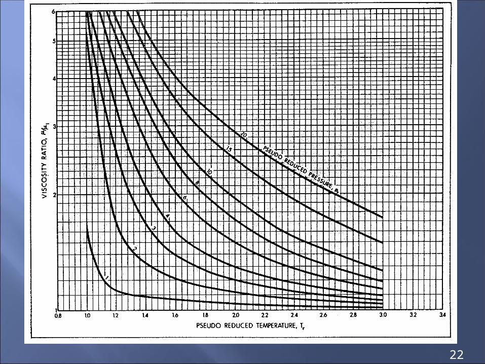
μ1 @ (520 °R = 60 °F) = 0.0103 cp (From Fig 2-12)
@ 300 psi & 60 °F = 1.05 (From Fig 2.12) 1
11
1.05 × 0.0103 = 0.010815 cp
09.1201082.0
Q6.048.0
D
Q48.0Re hgh
2.2016 Qh
09.12
0006.0
D
e 0.0000496 ≈ 0.00005
5.0
f
184.843,116
10052095.06.0
09.12)200400(1
7.14
52023.3
123.3
5225.05.052
221
5.0
fLTZ
Dpp
fp
TQ
gb
bh
17
We can calculate friction factor by following program

Third trial: Qh = 1,000,000 ft3/hr Re = 2.2 × 10⁶, f = 0.012 Qh = 1,066,633 ft3/hr
5.03/16225.0
3/1622
21
95.01005206.0
)09.12()200400(
7.14
520062.18062.18
LTZ
Dpp
p
TQ
gb
bh
= 989,859 ft3/hr
Second trial: Qh = 500,000 ft3/hr Re = 1.1 × 10⁶, f = 0.125 Qh = 1,045,083 ft3/hr
18

6182.2
4604.05394.022
21
07881.11
87.435 DLTZ
pp
p
TQ
gb
b
6182.24604.05394.02207881.1
09.126.0
1
95.0100520
200400
7.14
52087.435
530.2
49011.0510.022
21
02.11
737 DLTZ
pp
p
TQ
gb
b
530.249011.0510.02202.1
09.126.0
1
95.0100520
200400
7.14
520737
19

20

21
22

23

Example: Natural gas with 24 MMcfd measured at standard conditions will be delivered to a Riyadh city 300 miles from gas field. The gas is delivered to the pipeline at 1500 psia pressure, and it is transmitted through a pipeline of sufficient size, so that the pressure at the Riyadh is 50 psia. Assume specific gravity of natural gas is 0.6 and the temperature of the flow is 100 oF.
What is the pipeline size required?
Solution
I apply in Modified Panhandle equation to determine the required size:
DgzLT
PP
Pb
Tbq 53.2
51.0
961.0
22
21
02.1737
24

According to average pressure & temperature, we can determine the deviation factor ( z ):
Pavg. = ( P1 + P2 ) / 2 = ( 1500 + 50 ) / 2 = 775 psia.Tavg. = 100 oF = 560 oR
By computer program and based on Pavg. = 775 psia, Tavg. = 100 oF & g = 0.6, I get:
Z = 0.906
D = 7.597 7.6 inches
DMM 53.2
51.0
6.0 961.0906.0300)460100(
5021500202.1
7.14
4606073724
The minimum size required to transmitted 24 MMcfd is 7.597 7.6 inches
25

It is often desirable to increase the throughput of an existing pipeline by gathering gas from new gas wells. A common economical solution to these problems is to place one or more lines in parallel, either partially or throughout the whole length, or to replace a portion of the line with a larger one. This requires calculations involving flow in series, parallel, and series-parallel (looped) lines.
The philosophy involved in deriving the special relationships used in the solution of complex transmission systems is to express the various lengths and diameters of the pipe in the systems as equivalent lengths of common diameter or equivalent diameter of a common length, there equivalent means that both lines will have the same capacity with the same totally pressure drop.
For simplicity, illustrative examples will be based on the Weymouth equation.
26
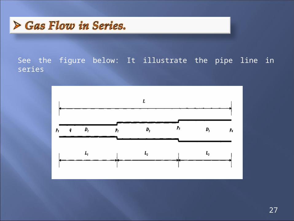
See the figure below: It illustrate the pipe line in series
27

Applying the Weymouth equation to each of the three segments gives:
28
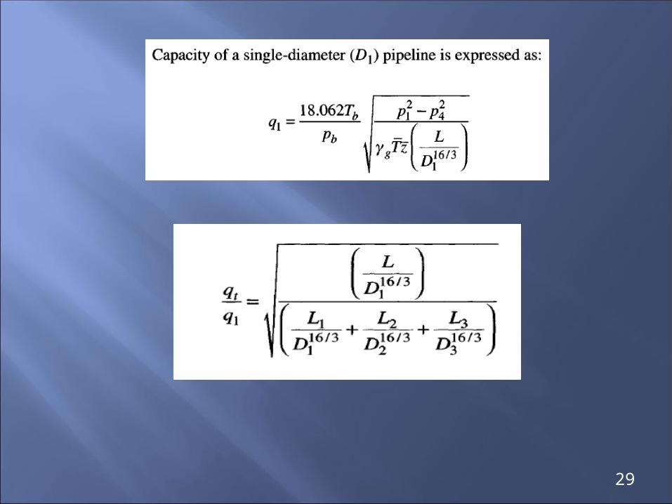
29

where
qh: gas flow rate, ft3/hr
Tb: base temperature, oR
Pb: base pressure, psia
D: inside diameter, inches
g: gas specific gravity ( air = 1 ), dimensionless
T: average following temperature, oR
L: length of pipeline, miles
z: gas deviation factor at average flowing pressure & temperature
M: symbol = 1000
30

Example:
G =0 .6 z = 0.95 Total length = 10 miles
1. Determine the capacity of the pipe line ?2. Determine P3 at conjunction point ?3. Determine LA’ if it is required to increase capacity 25%?
31

Solution1.
Qh =18.062(Tb/Pb) (( P12- P2
2)D16/3/ Z T L ))0.5
=18.062*520/14.7*((4002-2002)*416/3/0.6*520*7*0.95))0.5
= 195905.96 ft3/hr
LA’=LB (DA/DB)16/3 =3*(4/6)16/3 =0.345 mile
Lequ. = LA’ + LA
=0.345+7=7.345 mile
∆Qh% = (1/LAeq)0.5-(1/L)0.5/(1/L)0.5 = ((1/7.345)0.5-(1/10)0.5)/(1/10)0.5 = 16.7%
Qh NEW = Qh +( 0 .167 * Qh ) = 228622.26 ft3/hr
32

or directly by the relation
Qt / Q1 = (( L / D116/3) / ( L1 / D1
16/3 + L2 / D216/3 ))0.5
= (( 10 / 616/3 ) / ( 3/616/3 ) + ( 7 / 416/3))0.5
=1.167
QhNEW = 228622.2615 ft3/hr
2.
(P12 - P3
2) LA ZA= ( P32 - P2
2) LA” ZB
ZA = ZB = 0
To eliminate trail and error
( 1064000 - P32 ) * 7 = 0.345 * ( P32 - 13120 )
P3 = 393 psia33

3.
∆Qh%= (1/LAeq) * 0.5 - ( 1 / L ) * 0.5 / ( 1 / L ) * 0.5
0.25 = ( 1 / LAeq ) * 0.5 - ( 1 / 10 ) * 0.5 / ( 1 / 10) * 0.5
LAeq= 6.39mile
LA’= X ( DA / DB )16/3 = X ( 4 / 6 )16/3
=0.115 X
6.39 = 0.115 X + ( 10 – X )
X = LA = 6.07 mile
LA’ = 0.329 mile
34

By adding new parallel pipelines , What would be the resulting increase in capacity ?
What is the diameter that can obtain the given flow rate ( capacity ) ?
These questions are our target here
35

The new flow rate with both lines is
qt = q1 + q2
The length L is constant
L = L1 + L2
To calculate the increment in gas capacity, I apply in the following formulas:
or
36

ExamplExampleeLength of pipe line = 10 miles
Diameter of pipe line 1 = 4 inches
Diameter of pipe line 2 ( parallel to pipeline 1 ) = 6 inches
What would be the increase in capacity ?
37

Solution
The increase in the gas capacity = 211.33%
38

It considered the most complex design of transmission system. The part of pipeline is parallel. This is called looping or series-parallel system.
In the looped pipeline illustrated below, the original line consisted of segments ( A&B ) with the same diameter. In this system, a looping segment ( C ) has been added to increase the capacity of the pipeline system.
AB
C
Looped System
P1 P3 P2
39

Consider a three-segment looped pipeline depicted in Figure below.
qt
L2L1
P1
L
q1 D1
q2
P2P3
D2
D3 qt
Series – Parallel Pipelines
To calculate the total flow rate in pipeline for parallel section, apply in the following equ. :
40

To calculate the pressure drop in this section ( Parallel section ), apply in the To calculate the pressure drop in this section ( Parallel section ), apply in the following equation:following equation:
where
qh: gas flow rate, ft3/hr
Tb: base temperature, oR
Pb: base pressure, psia D: inside diameter, inches g: gas specific gravity ( air = 1 ), dimensionless T: average following temperature, oR L: length of pipeline, miles z: gas deviation factor at average flowing pressure &
temperature M: symbol = 1000
41

To calculate the flow rate in the second section ( Series ) with ( DTo calculate the flow rate in the second section ( Series ) with ( D3 3 ), apply in ), apply in
the following formula:the following formula:
To calculate the pressure drop ( P ) in the second section ( Series ) with ( D3 ), apply in the following formula:
42

To calculate the flow rate throughout transmission system, apply in the To calculate the flow rate throughout transmission system, apply in the following formula:following formula:
To calculate the pressure drop P throughout transmission system, apply in the following formula:
43

To calculate the increment in capacity or flow rate due to looped pipeline, apply in the following formula:
3/163
32
3/162
3/161
1
3/163
3
%
DL
DD
L
DL
qt
where
qh: gas flow rate, ft3/hr Tb: base temperature, oR Pb: base pressure, psia D: inside diameter, inches g: gas specific gravity ( air = 1 ), dimensionless T: average following temperature, oR L: length of pipeline, miles z: gas deviation factor at average flowing pressure & temperature q ( % ): increment in gas capacity due to looped pipeline, percent
44

To calculate the increment in capacity or flow rate due to looped pipeline, apply in the following formula:
1
231.21
111
1
DR
Y
X
231.21
11
21
11
DR
XY
45

where
X: increase in gas capacity, percent
Y: fraction of looped pipeline ( the ratio of looped pipeline length to the original length ), fraction
RD: is ratio of the looping pipe diameter to the original pipe diameter, dimensionless
46

The effects of looped line on the increase of gas flow rate for various pipe diameter ratios are shown in Figure below:
47

48

Example: Consider a 4-in pipeline that is 10 miles long. Assuming that the compression and delivery pressures will maintain unchanged, calculate gas capacity increases by using the following measures of improvement:
(a)Replace three miles of the 4-in pipeline by a 6-in pipeline segment.( Series pipeline )
This problem can be solved by following formula:
L = 10 miles L1 = 7 miles L2 = 3milesD1 = 4 in. D2 = 6 in.
3/163
33/16
2
23/16
1
1
3/161
1
D
L
D
L
D
L
D
L
qtq
49

The increase or improve in gas capacity = 16.68 %.
(b) Place a 6-in parallel pipeline to share gas transmission.
This problem can be solved by following formula:
D1 = 4 in. D2 = 6 in.
3/161
3/163
3/162
3/161
1 D
DDD
qtq
50

The increase or improve in gas capacity = 294.83 %.
(c) Loop three miles of the 4-in pipeline with a 6-in pipeline segment.
This problem can be solved by following formula:
L = 10 miles L1 = 7 miles L2 = 3 milesD1 = 4 in. D2 = 6 in.
3/163
32
3/162
3/161
1
3/163(%)
3
D
L
DD
L
D
L
qqtq
51

The increase or improve in gas capacity = 17.91%.
52

53

Example: A portion of a large gas gathering system consists of 6 in. line 9.4 miles that handling 7.6 MMscfd with an average specific gravity of 0.64. The upstream pressure is 375 psi and the average delivery pressure is 300 psi. The average temperature is 73 oF. Due to new well completion, it is desired to increase the capacity of this line 20% by looping with additional 6 in. line.
What length is required ?
Solution
I apply in the following formula to determine Y :
231.21
11
21
11
DR
XY
54

231.2)6/6(1
11
22.01
11
Y25.01
694444.01
Y
75.0
305556.0Y 407408.0Y
Ylength of looped pipeline
original length of pipeline
length of looped pipeline
9.4
407408.0length of looped pipeline
9.4
Length of looped pipeline = 9.4 0.407408 = 3.8296352 miles
It should be looped 3.83 miles with 6 in. to increase the capacity of this line 20%.
55

Example: A series pipeline consists of three lengths: 1. 30 miles of 6 inches pipe 2. 40 miles of 8 inches pipe 3. 50 miles of 10 inches pipe
Determine the equipment the equivalent lengths of 6, 8, & 10 inches ?
Solution
I apply in the following formula to determine the equivalent length at common pipeline diameter:
6 in. 8 in. 10 in.
30 miles 40 miles 50 miles
D
L
D
L
D
L
D
Le3/16
3
33/16
2
23/16
1
13/16
D
L
D
L
D
L
D
Le3/16
3
33/16
2
23/16
1
13/16
56

I get the following:
57

58

59
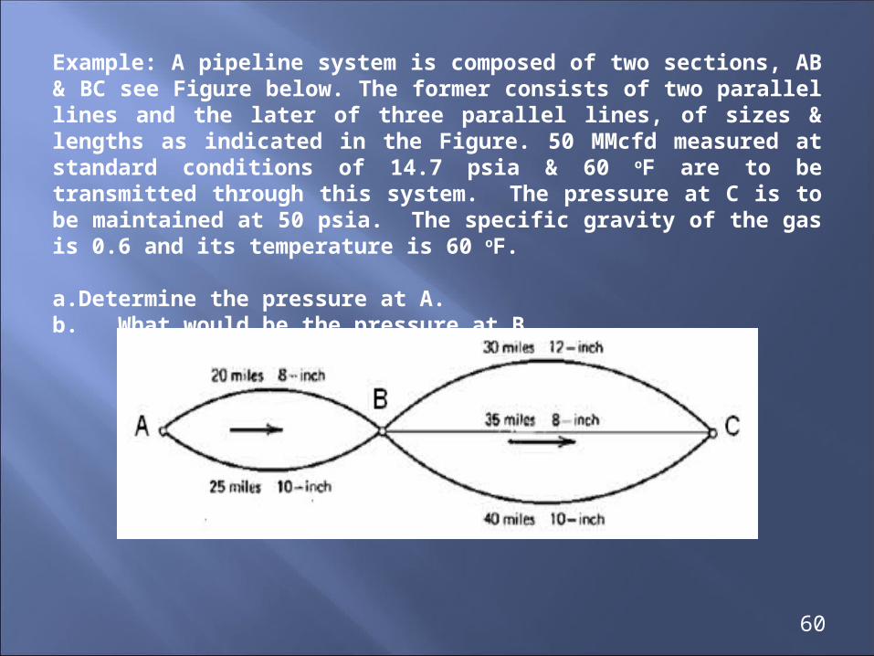
Example: A pipeline system is composed of two sections, AB & BC see Figure below. The former consists of two parallel lines and the later of three parallel lines, of sizes & lengths as indicated in the Figure. 50 MMcfd measured at standard conditions of 14.7 psia & 60 oF are to be transmitted through this system. The pressure at C is to be maintained at 50 psia. The specific gravity of the gas is 0.6 and its temperature is 60 oF.
a.Determine the pressure at A.b. What would be the pressure at B.
60

Solution
I determine the equivalent length with common diameter to convert parallel lines to series lines by following formula:
and I get for the section ( BC ):
L
D
L
D
L
D
Le
D5.0
3
3/83
5.02
3/82
5.01
3/81
5.0
3/8
61

and for section ( AB ):
To calculate pressure at ( B ), it need trail & error calculation. I assume the pressure at ( B ), then I calculate the flow rate of gas and compare it with given flow rate.
62

I apply in Weymouth equation for pipe line equation with size ( ID 15 inches ) to calculate the flow rate of gas at pipe line conditions as follows:
I get:
5.0
__
3/1622
21062.18
zLTg
DPP
Pb
Tbqh
Then, from results the pressure at ( B ) = 2289 psia 63
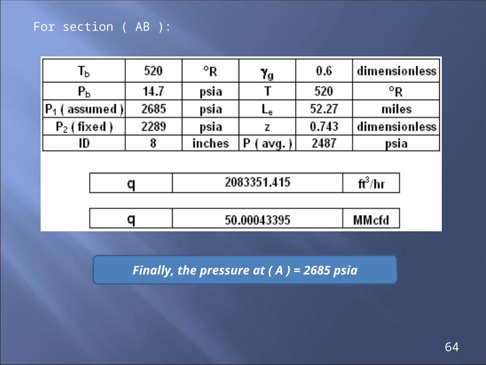
For section ( AB ):
Finally, the pressure at ( A ) = 2685 psia
64

Thanks for Allah
Thank you for Attention
65